WO2018207428A1 - Spray nozzle, coating forming device, and method for forming coating - Google Patents
Spray nozzle, coating forming device, and method for forming coating Download PDFInfo
- Publication number
- WO2018207428A1 WO2018207428A1 PCT/JP2018/006428 JP2018006428W WO2018207428A1 WO 2018207428 A1 WO2018207428 A1 WO 2018207428A1 JP 2018006428 W JP2018006428 W JP 2018006428W WO 2018207428 A1 WO2018207428 A1 WO 2018207428A1
- Authority
- WO
- WIPO (PCT)
- Prior art keywords
- carrier gas
- spray nozzle
- film
- orbit
- nozzle
- Prior art date
Links
Images


Classifications
-
- B—PERFORMING OPERATIONS; TRANSPORTING
- B05—SPRAYING OR ATOMISING IN GENERAL; APPLYING FLUENT MATERIALS TO SURFACES, IN GENERAL
- B05B—SPRAYING APPARATUS; ATOMISING APPARATUS; NOZZLES
- B05B1/00—Nozzles, spray heads or other outlets, with or without auxiliary devices such as valves, heating means
- B05B1/12—Nozzles, spray heads or other outlets, with or without auxiliary devices such as valves, heating means capable of producing different kinds of discharge, e.g. either jet or spray
-
- B—PERFORMING OPERATIONS; TRANSPORTING
- B05—SPRAYING OR ATOMISING IN GENERAL; APPLYING FLUENT MATERIALS TO SURFACES, IN GENERAL
- B05B—SPRAYING APPARATUS; ATOMISING APPARATUS; NOZZLES
- B05B7/00—Spraying apparatus for discharge of liquids or other fluent materials from two or more sources, e.g. of liquid and air, of powder and gas
- B05B7/14—Spraying apparatus for discharge of liquids or other fluent materials from two or more sources, e.g. of liquid and air, of powder and gas designed for spraying particulate materials
- B05B7/1481—Spray pistols or apparatus for discharging particulate material
- B05B7/1486—Spray pistols or apparatus for discharging particulate material for spraying particulate material in dry state
-
- B—PERFORMING OPERATIONS; TRANSPORTING
- B05—SPRAYING OR ATOMISING IN GENERAL; APPLYING FLUENT MATERIALS TO SURFACES, IN GENERAL
- B05B—SPRAYING APPARATUS; ATOMISING APPARATUS; NOZZLES
- B05B12/00—Arrangements for controlling delivery; Arrangements for controlling the spray area
- B05B12/16—Arrangements for controlling delivery; Arrangements for controlling the spray area for controlling the spray area
- B05B12/20—Masking elements, i.e. elements defining uncoated areas on an object to be coated
- B05B12/22—Masking elements, i.e. elements defining uncoated areas on an object to be coated movable relative to the spray area
-
- B—PERFORMING OPERATIONS; TRANSPORTING
- B05—SPRAYING OR ATOMISING IN GENERAL; APPLYING FLUENT MATERIALS TO SURFACES, IN GENERAL
- B05D—PROCESSES FOR APPLYING FLUENT MATERIALS TO SURFACES, IN GENERAL
- B05D1/00—Processes for applying liquids or other fluent materials
- B05D1/02—Processes for applying liquids or other fluent materials performed by spraying
- B05D1/08—Flame spraying
-
- C—CHEMISTRY; METALLURGY
- C23—COATING METALLIC MATERIAL; COATING MATERIAL WITH METALLIC MATERIAL; CHEMICAL SURFACE TREATMENT; DIFFUSION TREATMENT OF METALLIC MATERIAL; COATING BY VACUUM EVAPORATION, BY SPUTTERING, BY ION IMPLANTATION OR BY CHEMICAL VAPOUR DEPOSITION, IN GENERAL; INHIBITING CORROSION OF METALLIC MATERIAL OR INCRUSTATION IN GENERAL
- C23C—COATING METALLIC MATERIAL; COATING MATERIAL WITH METALLIC MATERIAL; SURFACE TREATMENT OF METALLIC MATERIAL BY DIFFUSION INTO THE SURFACE, BY CHEMICAL CONVERSION OR SUBSTITUTION; COATING BY VACUUM EVAPORATION, BY SPUTTERING, BY ION IMPLANTATION OR BY CHEMICAL VAPOUR DEPOSITION, IN GENERAL
- C23C24/00—Coating starting from inorganic powder
- C23C24/02—Coating starting from inorganic powder by application of pressure only
- C23C24/04—Impact or kinetic deposition of particles
-
- C—CHEMISTRY; METALLURGY
- C23—COATING METALLIC MATERIAL; COATING MATERIAL WITH METALLIC MATERIAL; CHEMICAL SURFACE TREATMENT; DIFFUSION TREATMENT OF METALLIC MATERIAL; COATING BY VACUUM EVAPORATION, BY SPUTTERING, BY ION IMPLANTATION OR BY CHEMICAL VAPOUR DEPOSITION, IN GENERAL; INHIBITING CORROSION OF METALLIC MATERIAL OR INCRUSTATION IN GENERAL
- C23C—COATING METALLIC MATERIAL; COATING MATERIAL WITH METALLIC MATERIAL; SURFACE TREATMENT OF METALLIC MATERIAL BY DIFFUSION INTO THE SURFACE, BY CHEMICAL CONVERSION OR SUBSTITUTION; COATING BY VACUUM EVAPORATION, BY SPUTTERING, BY ION IMPLANTATION OR BY CHEMICAL VAPOUR DEPOSITION, IN GENERAL
- C23C24/00—Coating starting from inorganic powder
- C23C24/08—Coating starting from inorganic powder by application of heat or pressure and heat
- C23C24/082—Coating starting from inorganic powder by application of heat or pressure and heat without intermediate formation of a liquid in the layer
- C23C24/085—Coating with metallic material, i.e. metals or metal alloys, optionally comprising hard particles, e.g. oxides, carbides or nitrides
- C23C24/087—Coating with metal alloys or metal elements only
-
- C—CHEMISTRY; METALLURGY
- C23—COATING METALLIC MATERIAL; COATING MATERIAL WITH METALLIC MATERIAL; CHEMICAL SURFACE TREATMENT; DIFFUSION TREATMENT OF METALLIC MATERIAL; COATING BY VACUUM EVAPORATION, BY SPUTTERING, BY ION IMPLANTATION OR BY CHEMICAL VAPOUR DEPOSITION, IN GENERAL; INHIBITING CORROSION OF METALLIC MATERIAL OR INCRUSTATION IN GENERAL
- C23C—COATING METALLIC MATERIAL; COATING MATERIAL WITH METALLIC MATERIAL; SURFACE TREATMENT OF METALLIC MATERIAL BY DIFFUSION INTO THE SURFACE, BY CHEMICAL CONVERSION OR SUBSTITUTION; COATING BY VACUUM EVAPORATION, BY SPUTTERING, BY ION IMPLANTATION OR BY CHEMICAL VAPOUR DEPOSITION, IN GENERAL
- C23C4/00—Coating by spraying the coating material in the molten state, e.g. by flame, plasma or electric discharge
- C23C4/01—Selective coating, e.g. pattern coating, without pre-treatment of the material to be coated
-
- C—CHEMISTRY; METALLURGY
- C23—COATING METALLIC MATERIAL; COATING MATERIAL WITH METALLIC MATERIAL; CHEMICAL SURFACE TREATMENT; DIFFUSION TREATMENT OF METALLIC MATERIAL; COATING BY VACUUM EVAPORATION, BY SPUTTERING, BY ION IMPLANTATION OR BY CHEMICAL VAPOUR DEPOSITION, IN GENERAL; INHIBITING CORROSION OF METALLIC MATERIAL OR INCRUSTATION IN GENERAL
- C23C—COATING METALLIC MATERIAL; COATING MATERIAL WITH METALLIC MATERIAL; SURFACE TREATMENT OF METALLIC MATERIAL BY DIFFUSION INTO THE SURFACE, BY CHEMICAL CONVERSION OR SUBSTITUTION; COATING BY VACUUM EVAPORATION, BY SPUTTERING, BY ION IMPLANTATION OR BY CHEMICAL VAPOUR DEPOSITION, IN GENERAL
- C23C4/00—Coating by spraying the coating material in the molten state, e.g. by flame, plasma or electric discharge
- C23C4/12—Coating by spraying the coating material in the molten state, e.g. by flame, plasma or electric discharge characterised by the method of spraying
-
- B—PERFORMING OPERATIONS; TRANSPORTING
- B05—SPRAYING OR ATOMISING IN GENERAL; APPLYING FLUENT MATERIALS TO SURFACES, IN GENERAL
- B05B—SPRAYING APPARATUS; ATOMISING APPARATUS; NOZZLES
- B05B7/00—Spraying apparatus for discharge of liquids or other fluent materials from two or more sources, e.g. of liquid and air, of powder and gas
- B05B7/16—Spraying apparatus for discharge of liquids or other fluent materials from two or more sources, e.g. of liquid and air, of powder and gas incorporating means for heating or cooling the material to be sprayed
- B05B7/1606—Spraying apparatus for discharge of liquids or other fluent materials from two or more sources, e.g. of liquid and air, of powder and gas incorporating means for heating or cooling the material to be sprayed the spraying of the material involving the use of an atomising fluid, e.g. air
- B05B7/1613—Spraying apparatus for discharge of liquids or other fluent materials from two or more sources, e.g. of liquid and air, of powder and gas incorporating means for heating or cooling the material to be sprayed the spraying of the material involving the use of an atomising fluid, e.g. air comprising means for heating the atomising fluid before mixing with the material to be sprayed
- B05B7/162—Spraying apparatus for discharge of liquids or other fluent materials from two or more sources, e.g. of liquid and air, of powder and gas incorporating means for heating or cooling the material to be sprayed the spraying of the material involving the use of an atomising fluid, e.g. air comprising means for heating the atomising fluid before mixing with the material to be sprayed and heat being transferred from the atomising fluid to the material to be sprayed
- B05B7/1626—Spraying apparatus for discharge of liquids or other fluent materials from two or more sources, e.g. of liquid and air, of powder and gas incorporating means for heating or cooling the material to be sprayed the spraying of the material involving the use of an atomising fluid, e.g. air comprising means for heating the atomising fluid before mixing with the material to be sprayed and heat being transferred from the atomising fluid to the material to be sprayed at the moment of mixing
Definitions
- the present invention relates to a spray nozzle, a film forming apparatus, and a film forming method for forming a film on a base material by injecting the film material together with the carrier gas onto the base material.
- a method of forming a film by a thermal spraying method has attracted attention.
- the cold spray method which is one of the thermal spraying methods
- (1) a carrier gas having a temperature lower than the melting point or softening temperature of the coating material is flowed at a high speed, and (2) the coating material is introduced into the carrier gas flow.
- Patent Documents 1 and 2 disclose a technique for forming a film using a cold spray method.
- the conventional cold spray method uses masking to form a film in a desired region.
- the masking has a problem that the film formation efficiency is lowered when there is an area not involved in the film formation.
- Patent Document 2 discloses a nozzle in which an opening is formed at the tip in order to improve film formation efficiency. However, even when the nozzle described in Patent Document 2 is used, it is not easy to efficiently form a film in a desired region.
- the present invention has been made in view of the above problems, and an object thereof is to realize a spray nozzle, a film forming apparatus, and a film forming method capable of easily controlling a film region. is there.
- a spray nozzle is a spray nozzle applied to a film forming apparatus that forms a film on a base material by injecting the film material onto the base material together with a carrier gas.
- the at least one orbit changing unit changes the orbit of the coating material.
- the coating region on the substrate is changed.
- the spray nozzle according to an embodiment of the present invention can control the film region on the substrate via the at least one orbit changing unit.
- the spray nozzle, the film forming apparatus, and the film forming method according to the present invention have an effect that the film region can be easily controlled.
- Embodiment 1 First, a cold spray apparatus (film forming apparatus) 100 using the spray nozzle 10 according to the present embodiment will be described with reference to FIG.
- the spray nozzle 10 is used for the cold spray method.
- the spray nozzle 10 can also be applied to other thermal spraying methods (such as flame spraying, high-speed flame spraying, HVOF, FVAF, or plasma spraying).
- the cold spray method can be roughly classified into a high pressure cold spray and a low pressure cold spray depending on the working gas pressure.
- the spray nozzle 10 according to the first embodiment can be applied to both high pressure cold spray and low pressure cold spray.
- a film forming method called a cold spray method has been used.
- a carrier gas having a temperature lower than the melting point or softening temperature of the coating material is made to flow at a high speed, and the coating material is injected into the carrier gas flow to accelerate it. And forming a film.
- the film formation principle of the cold spray method is understood as follows.
- the critical speed In order for the film material to adhere to and deposit on the substrate, a collision speed higher than a certain critical value is required, and this is called the critical speed.
- the critical speed When the coating material collides with the substrate at a speed lower than the critical speed, the substrate is worn away, and the substrate can only have a small crater-like depression.
- the critical speed varies depending on the material, size, shape, temperature, oxygen content, or material of the base material.
- the coating material examples include the following materials, but are not limited to these materials. 1. Pure metal Copper (Cu), Aluminum (Al), Titanium (Ti), Silver (Ag), Nickel (Ni), Zinc (Zn), Tin (Sn), Molybdenum (Mo), Iron (Fe), Tantalum (Ta ), Niobium (Nb), silicon (Si), chromium (Cr) 2. Low alloy steel Ancorsteel 100 3. Nickel-chromium alloy 50Ni-50Cr, 60Ni-40Cr, 80Ni-20Cr 4). Nickel-base superalloys Alloy625, Alloy718, Hastelloy C, In738LC 5).
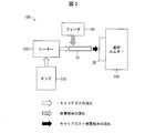
- FIG. 2 is a schematic view of the cold spray device 100.
- the cold spray device 100 includes a tank 110, a heater 120, a spray nozzle 10, a feeder 140, a substrate holder 150, and a control device (not shown).
- the tank 110 stores a carrier gas.
- the carrier gas is supplied from the tank 110 to the heater 120.
- the carrier gas include nitrogen, helium, air, or a mixed gas thereof.
- the pressure of the carrier gas is adjusted to be, for example, 70 PSI or more and 150 PSI or less (about 0.48 Mpa or more and about 1.03 Mpa or less) at the outlet of the tank 110.
- the pressure of the carrier gas at the outlet of the tank 110 is not limited to the above range, and is appropriately adjusted depending on the material and size of the coating material, the material of the base material, and the like.
- the heater 120 heats the carrier gas supplied from the tank 110. More specifically, the carrier gas is heated to a temperature lower than the melting point of the coating material supplied from the feeder 140 to the spray nozzle 10. For example, the carrier gas is heated in the range of 50 ° C. or more and 500 ° C. or less when measured at the outlet of the heater 120. However, the heating temperature of the carrier gas is not limited to the above range, and is appropriately adjusted depending on the material and size of the coating material, the material of the base material, and the like.
- the carrier gas is heated by the heater 120 and then supplied to the spray nozzle 10.
- the spray nozzle 10 accelerates the carrier gas heated by the heater 120 in the range of 300 m / s or more and 1200 m / s or less, and injects it toward the substrate 20.
- the speed of the carrier gas is not limited to the above range, and is appropriately adjusted depending on the material and size of the coating material, the material of the base material, and the like.
- the feeder 140 supplies the coating material into the flow of the carrier gas accelerated by the spray nozzle 10.
- the particle size of the coating material supplied from the feeder 140 is 1 ⁇ m or more and 50 ⁇ m or less.
- the coating material supplied from the feeder 140 is sprayed from the spray nozzle 10 to the substrate 20 together with the carrier gas.
- the base material holder 150 fixes the base material 20.
- a carrier gas and a coating material are sprayed from the spray nozzle 10 onto the base material 20 fixed to the base material holder 150.
- the distance between the surface of the substrate 20 and the tip of the spray nozzle 10 is adjusted, for example, in the range of 1 mm to 30 mm.
- the film forming speed is lowered. This is because the carrier gas ejected from the spray nozzle 10 flows back into the spray nozzle 10.
- a member such as a hose connected to the spray nozzle 10 may come off due to the pressure generated when the carrier gas flows backward.
- the film forming efficiency is lowered. This is because it becomes difficult for the carrier gas and the film forming material ejected from the spray nozzle 10 to reach the substrate 20.
- the distance between the surface of the base material 20 and the spray nozzle 10 is not limited to the above range, and is appropriately adjusted depending on the material and size of the coating material, the material of the base material, and the like.
- the control device controls the cold spray device 100 based on previously stored information and / or operator input. Specifically, the control device controls the pressure of the carrier gas supplied from the tank 110 to the heater 120, the temperature of the carrier gas heated by the heater 120, the type and amount of the coating material supplied from the feeder 140, and the base material 20. The distance between the surface and the spray nozzle 10 is controlled.
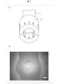
- FIG. 1 is a cross-sectional view of the spray nozzle 10.
- the spray nozzle 10 is used to form a film on the substrate 20 by injecting a film material onto the substrate 20 together with a carrier gas.
- the spray nozzle 10 includes a first body part 1, a second body part 2, a third body part 3, a nozzle tip part 4, and at least one track changing part 6.
- tip part 4 may be integrally formed.
- the first body part 1, the second body part 2, the third body part 3, and the nozzle tip part 4 are formed as separate bodies, and may be provided so as to be detachable from each other via screws or screws. Good.
- the first body part 1, the second body part 2, and the third body part are collectively referred to as a nozzle body.
- the first body part 1 and the second body part 2 may be collectively referred to as a nozzle body.
- the third body part and the nozzle front end part 4 may be referred to as a nozzle front end part by regarding the third body part as a part of the nozzle front end part 4.
- a commercially available standard spray nozzle may be used as it is.
- the spray nozzle 10 may be provided with a configuration such as a supply port through which the coating material is supplied from the feeder 140, but details thereof are omitted in the drawing.
- the flow direction of the carrier gas in the spray nozzle 10 is indicated by an arrow in FIG. 1 (direction from the right side to the left side of the drawing).
- the carrier gas is heated by the heater 120 and then supplied to the first body portion 1 of the spray nozzle 10.
- the passage path of the carrier gas is reduced along the flow of the carrier gas.
- the carrier gas increases in speed in the first body portion 1.
- the second body part 2 is provided following the first body part 1.
- the carrier gas passage way expands along the flow of the carrier gas.
- carrier gas expands in the 2nd body part 2, and film material accelerates by expansion of the carrier gas.
- the third body part 3 is provided following the second body part 2.
- the shape of the carrier gas passage is constant along the flow of the carrier gas.
- the carrier gas passage may be constant, enlarged, or reduced, but is preferably constant and enlarged.
- the nozzle tip 4 is provided following the third body 3.
- the shape of the carrier gas passage is constant along the flow of the carrier gas.
- the carrier gas passage may be constant, enlarged, or reduced, but is preferably constant and enlarged.
- the carrier gas passages in the first body part 1, the second body part 2, the third body part 3, and the nozzle tip part 4 each have a circular cross-sectional shape in a direction perpendicular to the carrier gas flow direction. is there.
- the shape may be other shapes.
- At least one track changing section 6 is inserted into the nozzle tip section 4. At least one trajectory changing portion 6 changes the trajectory of the coating material passing through the inside of the nozzle tip portion 4.
- details of the nozzle tip 4 and the at least one track changing unit 6 will be described with reference to FIG.
- At least one trajectory changing unit 6 traverses the carrier gas passage in the nozzle tip 4 in a direction perpendicular to the carrier gas flow direction.
- the at least one orbit changing unit 6 may cross the carrier gas passage in the nozzle tip 4 so as to have an angle greater than 0 ° and less than 90 ° with respect to the flow direction of the carrier gas.
- the at least one trajectory changing unit 6 does not necessarily need to cross the carrier gas passage in the nozzle tip 4 in a direction perpendicular to the flow direction of the carrier gas.
- the at least one orbit changing unit 6 is provided in various ways in the carrier gas passage in the nozzle tip 4 if the track of the coating material passing through the inside of the nozzle tip 4 is changed. May be.
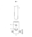
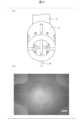
- FIG. 3 is a photograph showing a state in which the nozzle tip 4 is attached to the third body 3.
- FIG. 4 is a view showing a state in which the nozzle tip 4 is removed from the third body 3.
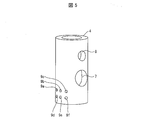
- FIG. 5 is a perspective view of the nozzle tip 4.
- the nozzle tip 4 can be attached to and detached from the third body 3.
- An opening 7 and an opening 8 are formed in the nozzle tip 4.
- the nozzle tip 4 and the third body 3 are fixed to each other by a screw 12 inserted into the opening 8.
- a part of the carrier gas is discharged to the outside of the nozzle tip 4 through the opening 7. Thereby, the backflow of the carrier gas inside the nozzle tip portion 4 is suppressed, and the coating material is sprayed onto the base material 20 without hindering the acceleration.
- At least one orbit changing portion 6 is inserted into the nozzle tip portion 4.
- at least one track changing portion 6 is inserted into the nozzle tip portion 4.
- six orbit changing portions 6a to 6f are inserted into the nozzle tip portion 4.
- openings 9a to 9f are formed in the nozzle tip portion 4 (when the openings 9a to 9f are not distinguished from each other, they are simply referred to as “openings 9”).
- Corresponding trajectory changing portions 6a to 6f are respectively inserted into the openings 9a to 9f.
- the shapes of the openings 9a to 9f are identical or substantially coincide with the shapes of the corresponding track changing portions 6a to 6f, respectively.
- the position of the opening 9 is not limited between the opening 7 and the tip of the nozzle tip 4, and may be between the opening 7 and the third body 3. Further, the nozzle tip 4 does not necessarily have the opening 7.
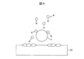
- FIG. 6 is a schematic diagram for explaining a change in the trajectory of the coating material M caused by at least one trajectory changing unit 6.
- the coating material M is supplied from the upper side to the lower side of the drawing.
- On the track of the coating material M at least one track changing unit 6 is provided.
- the coating material M collides with at least one orbit changing portion 6, the coating material M changes its orbit and reaches the surface of the base material 20 along the changed orbit.
- the nozzle tip portion 4 can control the coating region on the surface of the base material 20 by appropriately changing the quantity, size, shape, position, etc. of the at least one track changing portion 6.
- FIG. 7 is a photograph of the surface of the base material 20 on which the coating material is formed without using at least one orbit changing portion 6, (a) shows the nozzle tip 4, and (b) is the base material 20.
- the photograph of the surface of is shown.
- FIG. 8 is a photograph of the surface of the base material 20 on which the coating material is formed using at least one orbit changing section 6, wherein (a) shows the nozzle tip 4 and (b) is the base material.
- a photograph of 20 surfaces is shown.
- FIG. 9 is a photograph of the surface of the base material 20 on which a coating material is formed using two at least one orbit changing portions 6, wherein (a) shows the nozzle tip 4 and (b) is the base material.
- a photograph of 20 surfaces is shown.
- the vertical direction of the drawing is the direction in which the nozzle operates, and the inner side of the broken line indicates the coating region.
- the coating material is formed without using at least one orbit changing unit 6, a coating region is formed along the direction in which the nozzle moves, and in the direction perpendicular to the direction in which the nozzle moves (the left-right direction in the drawing) The film area does not expand (FIG. 7B).
- at least one orbit changing unit 6 changes the orbit of the coating material, so that the direction perpendicular to the direction in which the nozzle moves ( The film area also expands in the left-right direction (FIG. 8B and FIG. 9B). That is, in the case of FIGS. 8 and 9, the nozzle tip 4 can control the film formation region so that the film formation area is enlarged.
- the orbit change section 6 when the film material is formed using at least one orbit change section 6 (orbit change section 6a and orbit change section 6b), the orbit change section The film area immediately below 6a and the trajectory changing portion 6b is light in color. This indicates that the film thickness of the film region is small. However, the coating region formed between the track change portion 6a and the coating region immediately below the track change portion 6b is darker than the coating region immediately below the track change portion 6a and the track change portion 6b. This shows that the film thickness of the film
- region is larger.
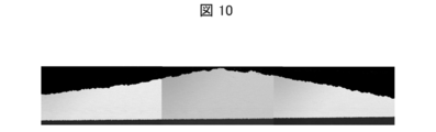
- FIG. 10 is a cross-sectional view of the film region when a film material is formed on the base material 20 without using at least one orbit changing unit 6.
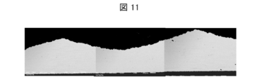
- FIG. 11 is a cross-sectional view of a film region when a film material is formed on the base material 20 using at least one orbit changing unit 6.
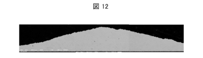
- FIG. 12 is a cross-sectional view of a coating region when a coating material is formed on the base material 20 using at least one orbit changing unit 6. 10 to 12, the conditions for spraying the coating material onto the substrate 20 are the same.
- the maximum film thickness is 0.700 mm, and the film thickness at a position 0.4 mm from the center is 0.590 mm.
- the maximum film thickness is 0.640 mm, and the central film thickness is 0.410 mm.
- the maximum film thickness is 0.713 mm, and the film thickness at a position 0.4 mm from the center is 0.626 mm.
- the film region is formed so that the film thickness near the center is small and the film thickness at a position slightly shifted from the center is maximized.
- the maximum film thickness and the film thickness at a position of 0.4 mm from the center are larger values than in the case of FIG.
- a film thickness difference of about 0.01 mm occurs. This numerical value of 0.01 mm is a film thickness difference that is understood by those skilled in the art to be a sufficiently significant film thickness difference.
- At least one orbit changing unit 6 changes the orbit of the coating material.
- the coating region on the substrate 20 changes.
- the spray nozzle 10 can control the coating region on the substrate 20 via the at least one trajectory changing unit 6.
- the design change of the nozzle body it was considered that the design change of the nozzle body was necessary.
- the spray nozzle 10 can control the film formation region in an arbitrary range (position, area, etc.) as compared with the existing spray nozzle. And the spray nozzle 10 can implement
- the at least one trajectory changing unit 6 is attached at various positions.
- the carrier gas passage in the nozzle tip 4 has a circular shape in a direction perpendicular to the flow direction of the carrier gas, and at least one orbit changing unit 6 has a rod shape. Furthermore, the at least one orbit changing unit 6 traverses the nozzle tip 4 so as to overlap the center of the circle in a direction perpendicular to the flow direction of the carrier gas.
- the carrier gas passage in the nozzle tip 4 has a circular shape in a direction perpendicular to the flow direction of the carrier gas, and the trajectory changing unit 6a and the trajectory changing unit 6b are both. It is rod-shaped. Further, the trajectory changing unit 6a and the trajectory changing unit 6b cross the nozzle tip 4 across the center of the circle in a direction perpendicular to the flow direction of the carrier gas. At this time, the trajectory changing unit 6a and the trajectory changing unit 6b may or may not be parallel to each other. When the trajectory changing portion 6a and the trajectory changing portion 6b are parallel to each other, the nozzle tip portion 4 into which the trajectory changing portion 6a and the trajectory changing portion 6b are inserted (more specifically, the opening of the nozzle tip portion 4). The processing 9) is easy. In addition, even when the trajectory changing unit 6a and the trajectory changing unit 6b are not parallel to each other, it is possible to control the coating region on the base material 20 that corresponds between the trajectory changing unit 6a and the trajectory changing unit 6b.
- the spray nozzle 10 can arrange
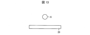
- FIG. 13 is a schematic view in the case where the cross-sectional shape of at least one orbit changing unit 6 in the flow direction of the carrier gas is a circle.
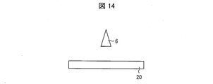
- FIG. 14 is a schematic diagram in the case where the cross-sectional shape of at least one orbit changing portion 6 in the carrier gas flow direction is a triangle.
- FIG. 15 is a schematic diagram in the case where the cross-sectional shape of at least one orbit changing unit 6 in the flow direction of the carrier gas is a rectangle.
- At least one orbit changing unit 6 can take various shapes. That is, at least one orbit changing unit 6 may be formed so that the cross section in the flow direction of the carrier gas has a shape that changes the orbit of the coating material so that the coating material reaches the substrate 20.
- the shape of the cross section of the at least one orbit changing section 6 in the flow direction of the carrier gas is a circle. In the example of FIG.
- the shape of the cross section in the carrier gas flow direction (the cross section in the direction perpendicular to the direction in which the at least one rod-shaped orbit change section 6 extends) of the at least one orbit change section 6 is a triangle. In the triangle, one of the three sides is parallel to the surface of the substrate 20. If the cross-sectional shape is a circle or a triangle, the at least one orbit changing unit 6 can change the orbit of the coating material to reach the base material 20. The at least one trajectory changing unit 6 can more reliably form a film on the base material 20, and therefore can more easily control the film region on the base material 20. Examples of other shapes of the cross section include a rhombus, a square, and a pentagon as a cross-sectional shape of at least one orbit changing portion 6 in the flow direction of the carrier gas.
- a coating material can be deposited on the upper surface of at least one orbit changing unit 6.
- the at least one orbit changing section 6 can change the orbit of the coating material.
- the coating region on the substrate 20 is also changed.
- at least one track changing section 6 is detachable from the nozzle tip section 4, when a coating material is deposited on the upper surface of at least one track changing section 6, at least one track changing section 6 is provided. Replace it.
- the spray nozzle 10 can implement
- the spray nozzle according to the first aspect of the present invention is a spray nozzle applied to a film forming apparatus that forms a film on a base material by spraying the film material onto the base material together with a carrier gas, the nozzle body, A nozzle tip connected to the tip of the nozzle body, and at least one orbit changing unit arranged in a passage of the carrier gas at the nozzle tip to change the track of the coating material. .
- the at least one orbit changing unit changes the orbit of the coating material.
- the coating region on the substrate is changed.
- the spray nozzle according to an embodiment of the present invention can control the film region on the substrate via the at least one orbit changing unit.
- the spray nozzle according to aspect 2 of the present invention may be configured such that, in aspect 1, the nozzle tip is detachable from the nozzle body.
- the nozzle tip when the at least one orbit changing unit is necessary, the nozzle tip may be attached to the nozzle body.
- a plurality of types of nozzle tip portions by preparing a plurality of types of nozzle tip portions, a plurality of patterns of film regions can be easily formed on the substrate.
- the spray nozzle according to one embodiment of the present invention can more easily control the film region on the substrate.
- the spray nozzle according to aspect 3 of the present invention may be configured such that in the above aspect 1 or 2, the at least one orbit changing unit is detachable from the nozzle tip.
- the at least one trajectory changing unit is easily replaced. Accordingly, by preparing a plurality of types of the at least one orbit changing portion, it is possible to easily form a plurality of patterns of film regions on the substrate.
- the spray nozzle according to one embodiment of the present invention can more easily control the film region on the substrate.
- the at least one orbit changing portion when it becomes necessary to replace the at least one orbit changing portion due to wear or the like, the at least one orbit changing portion can be easily replaced. Thereby, there is also an effect that an easy-to-use spray nozzle can be provided to the user.
- the spray nozzle according to Aspect 4 of the present invention is the spray nozzle according to any one of Aspects 1 to 3, wherein the at least one orbit changing portion is rod-shaped and arranged so as to cross the carrier gas passage. It is good also as composition which has.
- the spray nozzle according to Aspect 5 of the present invention is the spray nozzle according to Aspect 4, wherein the at least one trajectory changing unit cuts the carrier gas passage along a plane perpendicular to the flow direction of the carrier gas. It is good also as a structure which has been distribute
- the coating region on the substrate can be formed uniformly with the at least one orbit changing portion as the axis of symmetry.
- a spray nozzle according to aspect 6 of the present invention is the spray nozzle according to aspect 4, wherein there are a plurality of the at least one orbit changing unit, and each of the at least one orbit changing unit has a carrier gas passage through the carrier gas. It is good also as a structure arrange
- the thickness of the film region formed therebetween can be made larger than the film region immediately below each of the at least one orbit change portion. That is, the spray nozzle according to an embodiment of the present invention can control the film thickness of other film regions to be larger than that of a certain film region.
- the spray nozzle according to one embodiment of the present invention can control the coating region easily and flexibly.
- the spray nozzle according to Aspect 7 of the present invention is the spray nozzle according to any one of Aspects 1 to 6, wherein the at least one orbit changing section has a cross section in the flow direction of the carrier gas that changes the orbit of the coating material. It is good also as a structure currently formed in the shape which makes it let the said membrane
- a film can be more reliably formed on the base material, so that the film region on the base material can be more easily controlled.
- the spray nozzle according to aspect 8 of the present invention may be configured such that, in the aspect 7, the at least one orbit changing portion has a circular cross-sectional shape in the carrier gas flow direction.
- a film can be formed on the base material more efficiently.
- the spray nozzle according to aspect 9 of the present invention is the spray nozzle according to aspect 7, in which the at least one orbit changing portion has a triangular cross-sectional shape in the flow direction of the carrier gas, and the triangle is formed of three sides. One side may be parallel to the surface of the substrate.
- a film can be formed on the base material more efficiently.
- a film forming apparatus comprising the spray nozzle according to aspect 10 of the present invention is the film forming apparatus according to any one of aspects 1 to 9, wherein the spray nozzle according to any one of claims 1 to 9 is used. It is good also as a structure provided.
- the film forming apparatus can easily control the film region on the substrate.
- a method for forming a film comprising: using the spray nozzle according to aspect 11 of the present invention; and spraying the film material together with the carrier gas from the spray nozzle to form a film on the substrate.
- the coating material is sprayed from the spray nozzle together with the carrier gas, onto the substrate. It is good also as a method of forming a film.
- the film forming method according to an embodiment of the present invention can easily control the film region on the substrate.
- the film forming method according to aspect 12 of the present invention may be the method used in the thermal spraying method according to aspect 11 described above.
- the coating region on the substrate can be easily controlled in the thermal spraying method.
- the thermal spraying method melts or softens the coating material by heating, accelerates the coating material into fine particles, collides with the substrate surface, and solidifies and deposits the particles of the coating material crushed flatly.
- This is a kind of coating technology that forms a film.
- the method for forming the coating can be applied to the general thermal spraying method.
Abstract
The present invention implements a spray nozzle and the like that can easily control a coating region. A spray nozzle (10) is provided with: a nozzle main body (1, 2, 3); a nozzle tip part (4) connected to the front end of the nozzle main body (1, 2, 3); and at least one trajectory changing part (6) disposed within a path through which a carrier gas passes in the nozzle tip part (4) and changing the trajectory of a coating material.
Description
本発明は、キャリアガスと共に皮膜材料を基材に噴射することによって当該基材上に皮膜を形成するための、スプレーノズル、皮膜形成装置、及び皮膜の形成方法に関する。
The present invention relates to a spray nozzle, a film forming apparatus, and a film forming method for forming a film on a base material by injecting the film material together with the carrier gas onto the base material.
近年、エレクトロニクス分野では、電気部品及び電気回路の小型化・軽量化が進んでいる。これに伴い、微小領域に対する表面処理(表面改質)、及び微小領域に対する電極形成、といった要求が高まっている。
In recent years, in the electronics field, electric parts and electric circuits have been reduced in size and weight. Along with this, there has been a growing demand for surface treatment (surface modification) for micro regions and electrode formation for micro regions.
そのような要求に応えるため、近年は、溶射法による皮膜の形成方法が注目されている。たとえば、溶射法の一つであるコールドスプレー法は、(1)皮膜材料の融点または軟化温度よりも低い温度のキャリアガスを高速流にし、(2)そのキャリアガス流中に皮膜材料を投入し、加速させ、(3)固相状態のまま基板等に高速で衝突させて皮膜を形成する方法である。
In order to meet such demands, in recent years, a method of forming a film by a thermal spraying method has attracted attention. For example, in the cold spray method, which is one of the thermal spraying methods, (1) a carrier gas having a temperature lower than the melting point or softening temperature of the coating material is flowed at a high speed, and (2) the coating material is introduced into the carrier gas flow. (3) A method of forming a film by colliding with a substrate or the like at a high speed in a solid state.
コールドスプレー法を用いて皮膜を形成する技術が特許文献1、2に開示されている。
Patent Documents 1 and 2 disclose a technique for forming a film using a cold spray method.
従来のコールドスプレー法は、所望の領域に成膜するためマスキングを利用していた。しかしながら、マスキングは、成膜に関与しないエリアが存在する場合、成膜効率が低下するという問題点があった。
The conventional cold spray method uses masking to form a film in a desired region. However, the masking has a problem that the film formation efficiency is lowered when there is an area not involved in the film formation.
特許文献2は、成膜効率を改善するために、先端部に開口が形成されたノズルを開示する。しかしながら、特許文献2に記載のノズルを利用した場合においても、所望の領域に効率的に成膜することは容易ではない。
Patent Document 2 discloses a nozzle in which an opening is formed at the tip in order to improve film formation efficiency. However, even when the nozzle described in Patent Document 2 is used, it is not easy to efficiently form a film in a desired region.
本発明は、上記の問題点に鑑みてなされたものであり、その目的は、皮膜領域を容易に制御することが可能な、スプレーノズル、皮膜形成装置、及び皮膜の形成方法を実現することにある。
The present invention has been made in view of the above problems, and an object thereof is to realize a spray nozzle, a film forming apparatus, and a film forming method capable of easily controlling a film region. is there.
上記の課題を解決するために、本発明に係るスプレーノズルは、キャリアガスと共に皮膜材料を基材に噴射することによって当該基材上に皮膜を形成する皮膜形成装置に適用されるスプレーノズルであって、ノズル本体と、上記ノズル本体の先端に連結するノズル先端部と、上記ノズル先端部における上記キャリアガスの通過路内に配され、上記皮膜材料の軌道を変更する少なくとも1つの軌道変更部と、を備える構成である。
In order to solve the above problems, a spray nozzle according to the present invention is a spray nozzle applied to a film forming apparatus that forms a film on a base material by injecting the film material onto the base material together with a carrier gas. A nozzle body, a nozzle tip connected to the tip of the nozzle body, and at least one orbit changing unit arranged in a passage of the carrier gas at the nozzle tip to change the track of the coating material; .
上記の構成によれば、本発明の一実施形態に係るスプレーノズルでは、上記少なくとも1つの軌道変更部が上記皮膜材料の軌道を変更する。上記皮膜材料の軌道が変更すると、上記基材上の皮膜領域が変化する。このようにして、本発明の一実施形態に係るスプレーノズルは、上記少なくとも1つの軌道変更部を介して、上記基材上の皮膜領域を制御することができる。
According to the above configuration, in the spray nozzle according to an embodiment of the present invention, the at least one orbit changing unit changes the orbit of the coating material. When the trajectory of the coating material is changed, the coating region on the substrate is changed. In this way, the spray nozzle according to an embodiment of the present invention can control the film region on the substrate via the at least one orbit changing unit.
本発明によれば、本発明に係るスプレーノズル、皮膜形成装置、及び皮膜の形成方法は、皮膜領域を容易に制御できるという効果を奏する。
According to the present invention, the spray nozzle, the film forming apparatus, and the film forming method according to the present invention have an effect that the film region can be easily controlled.
以下、図面を参照しつつ、各実施形態について説明する。以下の説明では、同一の部品および構成要素には同一の符号を付している。それらの名称および機能も同じである。したがって、それらについての詳細な説明は繰り返さない。
Hereinafter, each embodiment will be described with reference to the drawings. In the following description, the same parts and components are denoted by the same reference numerals. Their names and functions are also the same. Therefore, detailed description thereof will not be repeated.
〔実施形態1〕
最初に、図2を参照して、本実施の形態に係るスプレーノズル10を用いるコールドスプレー装置(皮膜形成装置)100について説明する。Embodiment 1
First, a cold spray apparatus (film forming apparatus) 100 using thespray nozzle 10 according to the present embodiment will be described with reference to FIG.
最初に、図2を参照して、本実施の形態に係るスプレーノズル10を用いるコールドスプレー装置(皮膜形成装置)100について説明する。
First, a cold spray apparatus (film forming apparatus) 100 using the
以下の説明では、スプレーノズル10は、コールドスプレー法に用いられるものとする。しかしながら、スプレーノズル10は、他の溶射法(フレーム溶射、高速フレーム溶射、HVOF、FVAF、又はプラズマ溶射など)にも適用することができる。また、コールドスプレー法は、作動ガス圧に応じて、高圧コールドスプレーと低圧コールドスプレーとに大別できる。実施形態1に係るスプレーノズル10は、高圧コールドスプレーおよび低圧コールドスプレーの何れにも適用することができる。
In the following description, it is assumed that the spray nozzle 10 is used for the cold spray method. However, the spray nozzle 10 can also be applied to other thermal spraying methods (such as flame spraying, high-speed flame spraying, HVOF, FVAF, or plasma spraying). The cold spray method can be roughly classified into a high pressure cold spray and a low pressure cold spray depending on the working gas pressure. The spray nozzle 10 according to the first embodiment can be applied to both high pressure cold spray and low pressure cold spray.
〔コールドスプレーについて〕
近年、コールドスプレー法と呼ばれる皮膜形成法が利用されている。コールドスプレー法は、皮膜材料の融点または軟化温度よりも低い温度のキャリアガスを高速流にし、そのキャリアガス流中に皮膜材料を投入し加速させ、固相状態のまま基材等に高速で衝突させて皮膜を形成する方法である。 [About cold spray]
In recent years, a film forming method called a cold spray method has been used. In the cold spray method, a carrier gas having a temperature lower than the melting point or softening temperature of the coating material is made to flow at a high speed, and the coating material is injected into the carrier gas flow to accelerate it. And forming a film.
コールドスプレー法の成膜原理は、次のように理解されている。
The film formation principle of the cold spray method is understood as follows.
皮膜材料が基材に付着・堆積して成膜するには、ある臨界値以上の衝突速度が必要であり、これを臨界速度と称する。皮膜材料が臨界速度よりも低い速度で基材と衝突すると、基材が摩耗し、基材には小さなクレーター状の窪みしかできない。臨界速度は、皮膜材料の材質、大きさ、形状、温度、酸素含有量、又は基材の材質などによって変化する。
In order for the film material to adhere to and deposit on the substrate, a collision speed higher than a certain critical value is required, and this is called the critical speed. When the coating material collides with the substrate at a speed lower than the critical speed, the substrate is worn away, and the substrate can only have a small crater-like depression. The critical speed varies depending on the material, size, shape, temperature, oxygen content, or material of the base material.
皮膜材料が基材に対して臨界速度以上の速度で衝突すると、皮膜材料と基材(あるいはすでに成形された皮膜)との界面付近で大きなせん断による塑性変形が生じる。この塑性変形、及び衝突による固体内の強い衝撃波の発生に伴い、界面付近の温度も上昇し、その過程で、皮膜材料と基材、および、皮膜材料と皮膜(すでに付着した皮膜材料)との間で固相接合が生じる。
When the coating material collides with the base material at a speed higher than the critical speed, plastic deformation due to large shear occurs in the vicinity of the interface between the coating material and the base material (or the already formed film). With this plastic deformation and the generation of a strong shock wave in the solid due to the collision, the temperature near the interface also rises, and in the process, the coating material and the substrate, and the coating material and the coating (the coating material that has already adhered) Solid phase bonding occurs between them.
皮膜材料としては、以下の材料を例示することができるが、これらの材料に限定されるものではない。
1.純金属
銅(Cu)、アルミニウム(Al)、チタン(Ti)、銀(Ag)、ニッケル(Ni)、亜鉛(Zn)、錫(Sn)、モリブデン(Mo)、鉄(Fe)、タンタル(Ta)、ニオブ(Nb)、ケイ素(Si)、クロム(Cr)
2.低合金鋼
Ancorsteel 100
3.ニッケルクロム合金
50Ni-50Cr、60Ni-40Cr、80Ni-20Cr
4.ニッケル基超合金
Alloy625、Alloy718、Hastelloy C、In738LC
5.ステンレス鋼
SUS304/304L、SUS316/316L、SUS420、SUS440
6.亜鉛合金:Zn-20Al
7.アルミニウム合金:A1100、A6061
8.銅合金:C95800(Ni-AL Bronze)、60Cu-40Zn
9.MCrAlY:NiCrAlY、CoNiCrAlY
10.その他:アモルフォス(準結晶)金属、複合材料、サーメット、セラミックス
(コールドスプレー装置100)
図2は、コールドスプレー装置100の概略図である。図2に示すように、コールドスプレー装置100は、タンク110と、ヒーター120と、スプレーノズル10と、フィーダ140と、基材ホルダー150と、制御装置(不図示)とを備える。 Examples of the coating material include the following materials, but are not limited to these materials.
1. Pure metal Copper (Cu), Aluminum (Al), Titanium (Ti), Silver (Ag), Nickel (Ni), Zinc (Zn), Tin (Sn), Molybdenum (Mo), Iron (Fe), Tantalum (Ta ), Niobium (Nb), silicon (Si), chromium (Cr)
2. Low alloy steel Ancorsteel 100
3. Nickel-chromium alloy 50Ni-50Cr, 60Ni-40Cr, 80Ni-20Cr
4). Nickel-base superalloys Alloy625, Alloy718, Hastelloy C, In738LC
5). Stainless steel SUS304 / 304L, SUS316 / 316L, SUS420, SUS440
6). Zinc alloy: Zn-20Al
7). Aluminum alloy: A1100, A6061
8). Copper alloy: C95800 (Ni-AL Bronze), 60Cu-40Zn
9. MCrAlY: NiCrAlY, CoNiCrAlY
10. Others: Amorphous (quasicrystalline) metal, composite material, cermet, ceramics (cold spray device 100)
FIG. 2 is a schematic view of thecold spray device 100. As shown in FIG. 2, the cold spray device 100 includes a tank 110, a heater 120, a spray nozzle 10, a feeder 140, a substrate holder 150, and a control device (not shown).
1.純金属
銅(Cu)、アルミニウム(Al)、チタン(Ti)、銀(Ag)、ニッケル(Ni)、亜鉛(Zn)、錫(Sn)、モリブデン(Mo)、鉄(Fe)、タンタル(Ta)、ニオブ(Nb)、ケイ素(Si)、クロム(Cr)
2.低合金鋼
Ancorsteel 100
3.ニッケルクロム合金
50Ni-50Cr、60Ni-40Cr、80Ni-20Cr
4.ニッケル基超合金
Alloy625、Alloy718、Hastelloy C、In738LC
5.ステンレス鋼
SUS304/304L、SUS316/316L、SUS420、SUS440
6.亜鉛合金:Zn-20Al
7.アルミニウム合金:A1100、A6061
8.銅合金:C95800(Ni-AL Bronze)、60Cu-40Zn
9.MCrAlY:NiCrAlY、CoNiCrAlY
10.その他:アモルフォス(準結晶)金属、複合材料、サーメット、セラミックス
(コールドスプレー装置100)
図2は、コールドスプレー装置100の概略図である。図2に示すように、コールドスプレー装置100は、タンク110と、ヒーター120と、スプレーノズル10と、フィーダ140と、基材ホルダー150と、制御装置(不図示)とを備える。 Examples of the coating material include the following materials, but are not limited to these materials.
1. Pure metal Copper (Cu), Aluminum (Al), Titanium (Ti), Silver (Ag), Nickel (Ni), Zinc (Zn), Tin (Sn), Molybdenum (Mo), Iron (Fe), Tantalum (Ta ), Niobium (Nb), silicon (Si), chromium (Cr)
2. Low alloy steel Ancorsteel 100
3. Nickel-chromium alloy 50Ni-50Cr, 60Ni-40Cr, 80Ni-20Cr
4). Nickel-base superalloys Alloy625, Alloy718, Hastelloy C, In738LC
5). Stainless steel SUS304 / 304L, SUS316 / 316L, SUS420, SUS440
6). Zinc alloy: Zn-20Al
7). Aluminum alloy: A1100, A6061
8). Copper alloy: C95800 (Ni-AL Bronze), 60Cu-40Zn
9. MCrAlY: NiCrAlY, CoNiCrAlY
10. Others: Amorphous (quasicrystalline) metal, composite material, cermet, ceramics (cold spray device 100)
FIG. 2 is a schematic view of the
タンク110は、キャリアガスを貯蔵する。キャリアガスは、タンク110からヒーター120へ供給される。キャリアガスの一例として、窒素、ヘリウム、空気、またはそれらの混合ガスが挙げられる。キャリアガスの圧力は、タンク110の出口において、例えば70PSI以上150PSI以下(約0.48Mpa以上約1.03Mpa以下)となるよう調整される。ただし、タンク110の出口におけるキャリアガスの圧力は、上記の範囲に限られるものではなく、皮膜材料の材質、大きさ、又は基材の材質等により適宜調整される。
The tank 110 stores a carrier gas. The carrier gas is supplied from the tank 110 to the heater 120. Examples of the carrier gas include nitrogen, helium, air, or a mixed gas thereof. The pressure of the carrier gas is adjusted to be, for example, 70 PSI or more and 150 PSI or less (about 0.48 Mpa or more and about 1.03 Mpa or less) at the outlet of the tank 110. However, the pressure of the carrier gas at the outlet of the tank 110 is not limited to the above range, and is appropriately adjusted depending on the material and size of the coating material, the material of the base material, and the like.
ヒーター120は、タンク110から供給されたキャリアガスを加熱する。より具体的に、キャリアガスは、フィーダ140からスプレーノズル10に供給される皮膜材料の融点より低い温度に加熱される。例えば、キャリアガスは、ヒーター120の出口において測定したときに、50℃以上500℃以下の範囲で加熱される。ただし、キャリアガスの加熱温度は、上記の範囲に限られるものではなく、皮膜材料の材質、大きさ、又は基材の材質等により適宜調整される。
The heater 120 heats the carrier gas supplied from the tank 110. More specifically, the carrier gas is heated to a temperature lower than the melting point of the coating material supplied from the feeder 140 to the spray nozzle 10. For example, the carrier gas is heated in the range of 50 ° C. or more and 500 ° C. or less when measured at the outlet of the heater 120. However, the heating temperature of the carrier gas is not limited to the above range, and is appropriately adjusted depending on the material and size of the coating material, the material of the base material, and the like.
キャリアガスは、ヒーター120により加熱された後、スプレーノズル10へ供給される。
The carrier gas is heated by the heater 120 and then supplied to the spray nozzle 10.
スプレーノズル10は、ヒーター120により加熱されたキャリアガスを300m/s以上1200m/s以下の範囲で加速し、基材20へ向けて噴射する。なお、キャリアガスの速度は、上記の範囲に限られるものではなく、皮膜材料の材質、大きさ、又は基材の材質等により適宜調整される。
The spray nozzle 10 accelerates the carrier gas heated by the heater 120 in the range of 300 m / s or more and 1200 m / s or less, and injects it toward the substrate 20. The speed of the carrier gas is not limited to the above range, and is appropriately adjusted depending on the material and size of the coating material, the material of the base material, and the like.
フィーダ140は、スプレーノズル10により加速されるキャリアガスの流れの中に、皮膜材料を供給する。フィーダ140から供給される皮膜材料の粒径は、1μm以上50μm以下といった大きさである。フィーダ140から供給された皮膜材料は、スプレーノズル10からキャリアガスとともに基材20へ噴射される。
The feeder 140 supplies the coating material into the flow of the carrier gas accelerated by the spray nozzle 10. The particle size of the coating material supplied from the feeder 140 is 1 μm or more and 50 μm or less. The coating material supplied from the feeder 140 is sprayed from the spray nozzle 10 to the substrate 20 together with the carrier gas.
基材ホルダー150は、基材20を固定する。基材ホルダー150に固定された基材20に対して、キャリアガスおよび皮膜材料がスプレーノズル10から噴射される。基材20の表面とスプレーノズル10の先端との距離は、例えば、1mm以上30mm以下の範囲で調整される。基材20の表面とスプレーノズル10の先端との距離が1mmよりも近いと成膜速度が低下する。これは、スプレーノズル10から噴出したキャリアガスがスプレーノズル10内に逆流するためである。このとき、キャリアガスが逆流した際に生じる圧力により、スプレーノズル10に接続された部材(ホース等)が外れる場合もある。一方、基材20の表面とスプレーノズル10の先端との距離が30mmよりも離れると成膜効率が低下する。これは、スプレーノズル10から噴出したキャリアガス及び成膜材料が基材20に到達し難くなるである。
The base material holder 150 fixes the base material 20. A carrier gas and a coating material are sprayed from the spray nozzle 10 onto the base material 20 fixed to the base material holder 150. The distance between the surface of the substrate 20 and the tip of the spray nozzle 10 is adjusted, for example, in the range of 1 mm to 30 mm. When the distance between the surface of the substrate 20 and the tip of the spray nozzle 10 is shorter than 1 mm, the film forming speed is lowered. This is because the carrier gas ejected from the spray nozzle 10 flows back into the spray nozzle 10. At this time, a member (such as a hose) connected to the spray nozzle 10 may come off due to the pressure generated when the carrier gas flows backward. On the other hand, if the distance between the surface of the substrate 20 and the tip of the spray nozzle 10 is more than 30 mm, the film forming efficiency is lowered. This is because it becomes difficult for the carrier gas and the film forming material ejected from the spray nozzle 10 to reach the substrate 20.
ただし、基材20の表面とスプレーノズル10との距離は、上記の範囲に限られるものではなく、皮膜材料の材質、大きさ、又は基材の材質等により適宜調整される。
However, the distance between the surface of the base material 20 and the spray nozzle 10 is not limited to the above range, and is appropriately adjusted depending on the material and size of the coating material, the material of the base material, and the like.
制御装置は、予め記憶した情報、および/または、オペレーターの入力に基づいて、コールドスプレー装置100を制御する。具体的に、制御装置は、タンク110からヒーター120へ供給されるキャリアガスの圧力、ヒーター120により加熱されるキャリアガスの温度、フィーダ140から供給される皮膜材料の種類および量、及び基材20の表面とスプレーノズル10との距離などを制御する。
The control device controls the cold spray device 100 based on previously stored information and / or operator input. Specifically, the control device controls the pressure of the carrier gas supplied from the tank 110 to the heater 120, the temperature of the carrier gas heated by the heater 120, the type and amount of the coating material supplied from the feeder 140, and the base material 20. The distance between the surface and the spray nozzle 10 is controlled.
(スプレーノズル10)
次に、スプレーノズル10を図1等により説明する。図1は、スプレーノズル10の断面図である。 (Spray nozzle 10)
Next, thespray nozzle 10 will be described with reference to FIG. FIG. 1 is a cross-sectional view of the spray nozzle 10.
次に、スプレーノズル10を図1等により説明する。図1は、スプレーノズル10の断面図である。 (Spray nozzle 10)
Next, the
スプレーノズル10は、キャリアガスと共に皮膜材料を基材20に噴射することによって基材20上に皮膜を形成するために用いられる。スプレーノズル10は、第1胴体部1と、第2胴体部2と、第3胴体部3と、ノズル先端部4と、少なくとも1つの軌道変更部6と、を備える。
The spray nozzle 10 is used to form a film on the substrate 20 by injecting a film material onto the substrate 20 together with a carrier gas. The spray nozzle 10 includes a first body part 1, a second body part 2, a third body part 3, a nozzle tip part 4, and at least one track changing part 6.
なお、第1胴体部1、第2胴体部2、第3胴体部3、及びノズル先端部4は、一体に形成されてもよい。あるいは、第1胴体部1、第2胴体部2、第3胴体部3、及びノズル先端部4は、それぞれ別体として形成され、螺合あるいは螺子等を介して互いに脱着可能に設けられてもよい。
In addition, the 1st body part 1, the 2nd body part 2, the 3rd body part 3, and the nozzle front-end | tip part 4 may be integrally formed. Alternatively, the first body part 1, the second body part 2, the third body part 3, and the nozzle tip part 4 are formed as separate bodies, and may be provided so as to be detachable from each other via screws or screws. Good.
また、第1胴体部1、第2胴体部2、及び第3胴体部を総称してノズル本体という。ただし、第1胴体部1、及び第2胴体部2を総称してノズル本体と称する場合もある。この場合、第3胴体部をノズル先端部4の一部とみなして、第3胴体部及びノズル先端部4をノズル先端部と称してよい。ノズル本体は、市販されている標準スプレーノズルをそのまま使用してよい。
The first body part 1, the second body part 2, and the third body part are collectively referred to as a nozzle body. However, the first body part 1 and the second body part 2 may be collectively referred to as a nozzle body. In this case, the third body part and the nozzle front end part 4 may be referred to as a nozzle front end part by regarding the third body part as a part of the nozzle front end part 4. As the nozzle body, a commercially available standard spray nozzle may be used as it is.
スプレーノズル10は、フィーダ140から皮膜材料が供給される供給口などの構成を備えてよいが、図中ではその詳細を省略している。
The spray nozzle 10 may be provided with a configuration such as a supply port through which the coating material is supplied from the feeder 140, but details thereof are omitted in the drawing.
スプレーノズル10におけるキャリアガスの流れ方向は、図1中の矢印で示される(図面の右側から左側に向かう方向)。キャリアガスは、ヒーター120により加熱された後、スプレーノズル10の第1胴体部1に供給される。
The flow direction of the carrier gas in the spray nozzle 10 is indicated by an arrow in FIG. 1 (direction from the right side to the left side of the drawing). The carrier gas is heated by the heater 120 and then supplied to the first body portion 1 of the spray nozzle 10.
第1胴体部1では、キャリアガスの通過路が当該キャリアガスの流れに沿って縮小する。これにより、キャリアガスは、第1胴体部1において速度を増す。
In the first body part 1, the passage path of the carrier gas is reduced along the flow of the carrier gas. As a result, the carrier gas increases in speed in the first body portion 1.
第1胴体部1に続いて第2胴体部2が設けられる。第2胴体部2では、キャリアガスの通過路が当該キャリアガスの流れに沿って拡大する。これにより、スプレーノズル10では、第2胴体部2にてキャリアガスが膨張し、そのキャリアガスの膨張によって皮膜材料が加速する。
The second body part 2 is provided following the first body part 1. In the second body part 2, the carrier gas passage way expands along the flow of the carrier gas. Thereby, in spray nozzle 10, carrier gas expands in the 2nd body part 2, and film material accelerates by expansion of the carrier gas.
第2胴体部2に続いて第3胴体部3が設けられる。第3胴体部3では、キャリアガスの通過路の形状は、当該キャリアガスの流れに沿って一定である。なお、第3胴体部3では、キャリアガスの通過路は、一定、拡大、あるいは縮小の何れであってもよいが、一定、拡大がより好ましい。
The third body part 3 is provided following the second body part 2. In the third body 3, the shape of the carrier gas passage is constant along the flow of the carrier gas. In the third body portion 3, the carrier gas passage may be constant, enlarged, or reduced, but is preferably constant and enlarged.
第3胴体部3に続いてノズル先端部4が設けられる。ノズル先端部4では、キャリアガスの通過路の形状は、当該キャリアガスの流れに沿って一定である。第3胴体部3では、キャリアガスの通過路は、一定、拡大、あるいは縮小の何れであってもよいが、一定、拡大がより好ましい。
The nozzle tip 4 is provided following the third body 3. In the nozzle tip 4, the shape of the carrier gas passage is constant along the flow of the carrier gas. In the third body 3, the carrier gas passage may be constant, enlarged, or reduced, but is preferably constant and enlarged.
第1胴体部1、第2胴体部2、第3胴体部3、及びノズル先端部4におけるキャリアガスの通過路はそれぞれ、キャリアガスの流れ方向に対して垂直な方向における断面の形状は円形である。しかしながら、当該形状は他の形状であってもよい。
The carrier gas passages in the first body part 1, the second body part 2, the third body part 3, and the nozzle tip part 4 each have a circular cross-sectional shape in a direction perpendicular to the carrier gas flow direction. is there. However, the shape may be other shapes.
ノズル先端部4には少なくとも1つの軌道変更部6が挿入される。少なくとも1つの軌道変更部6は、ノズル先端部4の内部を通過する皮膜材料の軌道を変更する。以下、ノズル先端部4、及び少なくとも1つの軌道変更部6の詳細を図3等により説明する。
At least one track changing section 6 is inserted into the nozzle tip section 4. At least one trajectory changing portion 6 changes the trajectory of the coating material passing through the inside of the nozzle tip portion 4. Hereinafter, details of the nozzle tip 4 and the at least one track changing unit 6 will be described with reference to FIG.
なお、以下の説明では、少なくとも1つの軌道変更部6は、キャリアガスの流れ方向に対して垂直な方向において、ノズル先端部4内のキャリアガスの通過路を横断するものとして説明する。ただし、少なくとも1つの軌道変更部6は、キャリアガスの流れ方向に対して0°より大きく90°未満の角度を有するように、ノズル先端部4内のキャリアガスの通過路を横断してもよい。あるいは、少なくとも1つの軌道変更部6は、キャリアガスの流れ方向に対して垂直な方向において、ノズル先端部4内のキャリアガスの通過路を必ずしも横断する必要はない。
In the following description, it is assumed that at least one trajectory changing unit 6 traverses the carrier gas passage in the nozzle tip 4 in a direction perpendicular to the carrier gas flow direction. However, the at least one orbit changing unit 6 may cross the carrier gas passage in the nozzle tip 4 so as to have an angle greater than 0 ° and less than 90 ° with respect to the flow direction of the carrier gas. . Alternatively, the at least one trajectory changing unit 6 does not necessarily need to cross the carrier gas passage in the nozzle tip 4 in a direction perpendicular to the flow direction of the carrier gas.
このように、少なくとも1つの軌道変更部6は、ノズル先端部4の内部を通過する皮膜材料の軌道を変更するのであれば、ノズル先端部4内のキャリアガスの通過路に様々な態様で設けられてよい。
As described above, the at least one orbit changing unit 6 is provided in various ways in the carrier gas passage in the nozzle tip 4 if the track of the coating material passing through the inside of the nozzle tip 4 is changed. May be.
(ノズル先端部4、及び少なくとも1つの軌道変更部6について)
図3は、第3胴体部3にノズル先端部4が取り付けられた様子を示す写真である。図4は、第3胴体部3からノズル先端部4が取り外された様子を示す図である。図5は、ノズル先端部4の斜視図である。 (Regarding thenozzle tip portion 4 and at least one track changing portion 6)
FIG. 3 is a photograph showing a state in which thenozzle tip 4 is attached to the third body 3. FIG. 4 is a view showing a state in which the nozzle tip 4 is removed from the third body 3. FIG. 5 is a perspective view of the nozzle tip 4.
図3は、第3胴体部3にノズル先端部4が取り付けられた様子を示す写真である。図4は、第3胴体部3からノズル先端部4が取り外された様子を示す図である。図5は、ノズル先端部4の斜視図である。 (Regarding the
FIG. 3 is a photograph showing a state in which the
図3、及び図4に示すように、ノズル先端部4は、第3胴体部3に対して着脱可能である。ノズル先端部4には、開口7、及び開口8が形成されている。ノズル先端部4及び第3胴体部3は、開口8に挿入される螺子12によって互いに固定される。
As shown in FIGS. 3 and 4, the nozzle tip 4 can be attached to and detached from the third body 3. An opening 7 and an opening 8 are formed in the nozzle tip 4. The nozzle tip 4 and the third body 3 are fixed to each other by a screw 12 inserted into the opening 8.
キャリアガスの一部は、開口7を通してノズル先端部4の外部に放出される。これにより、ノズル先端部4の内部におけるキャリアガスの逆流が抑制されて、皮膜材料はその加速が阻害されることなく基材20に対して噴射される。
A part of the carrier gas is discharged to the outside of the nozzle tip 4 through the opening 7. Thereby, the backflow of the carrier gas inside the nozzle tip portion 4 is suppressed, and the coating material is sprayed onto the base material 20 without hindering the acceleration.
図3、及び図4に示すように、ノズル先端部4には、少なくとも1つの軌道変更部6が挿入される。図3では、ノズル先端部4には、少なくとも1つの軌道変更部6が1つ挿入されている。図4では、ノズル先端部4には6つの軌道変更部6a~6fが挿入されている。
As shown in FIGS. 3 and 4, at least one orbit changing portion 6 is inserted into the nozzle tip portion 4. In FIG. 3, at least one track changing portion 6 is inserted into the nozzle tip portion 4. In FIG. 4, six orbit changing portions 6a to 6f are inserted into the nozzle tip portion 4.
図5を参照して説明すると、ノズル先端部4には開口9a~9fが形成されている(開口9a~9fをそれぞれ区別しないときは、単に「開口9」と称する)。開口9a~9fはそれぞれ、対応する軌道変更部6a~6fがそれぞれ挿入される。開口9a~9fの形状はそれぞれ、対応する軌道変更部6a~6fの形状に一致、又は略一致する。
Referring to FIG. 5, openings 9a to 9f are formed in the nozzle tip portion 4 (when the openings 9a to 9f are not distinguished from each other, they are simply referred to as “openings 9”). Corresponding trajectory changing portions 6a to 6f are respectively inserted into the openings 9a to 9f. The shapes of the openings 9a to 9f are identical or substantially coincide with the shapes of the corresponding track changing portions 6a to 6f, respectively.
開口9の位置は、開口7とノズル先端部4の先端との間に限定されず、開口7と第3胴体部3との間であってもよい。また、ノズル先端部4は、必ずしも開口7を有していなくてもよい。
The position of the opening 9 is not limited between the opening 7 and the tip of the nozzle tip 4, and may be between the opening 7 and the third body 3. Further, the nozzle tip 4 does not necessarily have the opening 7.
(軌道変更部により生ずる皮膜材料の軌道の変化)
図6は、少なくとも1つの軌道変更部6により生ずる皮膜材料Mの軌道の変化を説明する概略図である。図6において、図面上側から下側に向かって皮膜材料Mが供給される。皮膜材料Mの軌道上には少なくとも1つの軌道変更部6が設けられている。少なくとも1つの軌道変更部6に皮膜材料Mが衝突すると、皮膜材料Mは、その軌道を変化させ、変化した後の軌道に沿って基材20の表面に到達する。その結果、ノズル先端部4が少なくとも1つの軌道変更部6を備えない場合と比較すると、基材20上の皮膜領域が変化する。このようにして、ノズル先端部4は、少なくとも1つの軌道変更部6の数量、サイズ、形状、又は位置等を適宜変化させることにより基材20の表面における皮膜領域を制御することができる。 (Changes in orbit of coating material caused by orbit change section)
FIG. 6 is a schematic diagram for explaining a change in the trajectory of the coating material M caused by at least onetrajectory changing unit 6. In FIG. 6, the coating material M is supplied from the upper side to the lower side of the drawing. On the track of the coating material M, at least one track changing unit 6 is provided. When the coating material M collides with at least one orbit changing portion 6, the coating material M changes its orbit and reaches the surface of the base material 20 along the changed orbit. As a result, compared with the case where the nozzle tip portion 4 does not include at least one orbit change portion 6, the coating region on the substrate 20 changes. In this way, the nozzle tip portion 4 can control the coating region on the surface of the base material 20 by appropriately changing the quantity, size, shape, position, etc. of the at least one track changing portion 6.
図6は、少なくとも1つの軌道変更部6により生ずる皮膜材料Mの軌道の変化を説明する概略図である。図6において、図面上側から下側に向かって皮膜材料Mが供給される。皮膜材料Mの軌道上には少なくとも1つの軌道変更部6が設けられている。少なくとも1つの軌道変更部6に皮膜材料Mが衝突すると、皮膜材料Mは、その軌道を変化させ、変化した後の軌道に沿って基材20の表面に到達する。その結果、ノズル先端部4が少なくとも1つの軌道変更部6を備えない場合と比較すると、基材20上の皮膜領域が変化する。このようにして、ノズル先端部4は、少なくとも1つの軌道変更部6の数量、サイズ、形状、又は位置等を適宜変化させることにより基材20の表面における皮膜領域を制御することができる。 (Changes in orbit of coating material caused by orbit change section)
FIG. 6 is a schematic diagram for explaining a change in the trajectory of the coating material M caused by at least one
次に、成膜後の基材20の表面の様子を図7等により説明する。
Next, the state of the surface of the substrate 20 after film formation will be described with reference to FIG.
(成膜後の基材20の表面観察)
図7は、少なくとも1つの軌道変更部6を使用せずに皮膜材料を成膜した基材20の表面の写真であり、(a)はノズル先端部4を示し、(b)は基材20の表面の写真を示す。図8は、少なくとも1つの軌道変更部6を1つ使用して皮膜材料を成膜した基材20の表面の写真であり、(a)はノズル先端部4を示し、(b)は基材20の表面の写真を示す。図9は、少なくとも1つの軌道変更部6を2つ使用して皮膜材料を成膜した基材20の表面の写真であり、(a)はノズル先端部4を示し、(b)は基材20の表面の写真を示す。図7(b)、図8(b)、及び図9(b)それぞれにおいて、図面上下方向がノズルの動作する方向であり、破線の内側が皮膜領域を示す。 (Surface observation ofsubstrate 20 after film formation)
FIG. 7 is a photograph of the surface of thebase material 20 on which the coating material is formed without using at least one orbit changing portion 6, (a) shows the nozzle tip 4, and (b) is the base material 20. The photograph of the surface of is shown. FIG. 8 is a photograph of the surface of the base material 20 on which the coating material is formed using at least one orbit changing section 6, wherein (a) shows the nozzle tip 4 and (b) is the base material. A photograph of 20 surfaces is shown. FIG. 9 is a photograph of the surface of the base material 20 on which a coating material is formed using two at least one orbit changing portions 6, wherein (a) shows the nozzle tip 4 and (b) is the base material. A photograph of 20 surfaces is shown. In each of FIG. 7B, FIG. 8B, and FIG. 9B, the vertical direction of the drawing is the direction in which the nozzle operates, and the inner side of the broken line indicates the coating region.
図7は、少なくとも1つの軌道変更部6を使用せずに皮膜材料を成膜した基材20の表面の写真であり、(a)はノズル先端部4を示し、(b)は基材20の表面の写真を示す。図8は、少なくとも1つの軌道変更部6を1つ使用して皮膜材料を成膜した基材20の表面の写真であり、(a)はノズル先端部4を示し、(b)は基材20の表面の写真を示す。図9は、少なくとも1つの軌道変更部6を2つ使用して皮膜材料を成膜した基材20の表面の写真であり、(a)はノズル先端部4を示し、(b)は基材20の表面の写真を示す。図7(b)、図8(b)、及び図9(b)それぞれにおいて、図面上下方向がノズルの動作する方向であり、破線の内側が皮膜領域を示す。 (Surface observation of
FIG. 7 is a photograph of the surface of the
少なくとも1つの軌道変更部6を使用せずに皮膜材料を成膜した場合には、ノズルが動く方向に沿って皮膜領域が形成され、ノズルが動く方向と垂直な方向(図面左右方向)には皮膜領域は拡大しない(図7(b))。一方、少なくとも1つの軌道変更部6を使用して皮膜材料を成膜した場合には、少なくとも1つの軌道変更部6が皮膜材料の軌道を変化させることにより、ノズルが動く方向と垂直な方向(図面左右方向)にも皮膜領域が拡大する(図8(b)、及び図9(b))。つまり、図8、及び図9の場合には、ノズル先端部4は、成膜面積が拡大するように成膜領域を制御することができる。
When the coating material is formed without using at least one orbit changing unit 6, a coating region is formed along the direction in which the nozzle moves, and in the direction perpendicular to the direction in which the nozzle moves (the left-right direction in the drawing) The film area does not expand (FIG. 7B). On the other hand, when the coating material is formed using at least one orbit changing unit 6, at least one orbit changing unit 6 changes the orbit of the coating material, so that the direction perpendicular to the direction in which the nozzle moves ( The film area also expands in the left-right direction (FIG. 8B and FIG. 9B). That is, in the case of FIGS. 8 and 9, the nozzle tip 4 can control the film formation region so that the film formation area is enlarged.
また、図9(b)に示すように、少なくとも1つの軌道変更部6を2つ(軌道変更部6a、及び軌道変更部6b)使用して皮膜材料を成膜した場合には、軌道変更部6a、及び軌道変更部6bの直下の皮膜領域は、色が薄い。これは、皮膜領域の膜厚が小さいことを示す。しかしながら、軌道変更部6a、及び軌道変更部6bの直下の皮膜領域の間に形成された皮膜領域は、軌道変更部6a、及び軌道変更部6bの直下の皮膜領域よりも色が濃い。これは、軌道変更部6a、及び軌道変更部6bそれぞれの直下の皮膜領域よりも、その間に形成された皮膜領域の膜厚が大きいことを示す。
In addition, as shown in FIG. 9B, when the film material is formed using at least one orbit change section 6 (orbit change section 6a and orbit change section 6b), the orbit change section The film area immediately below 6a and the trajectory changing portion 6b is light in color. This indicates that the film thickness of the film region is small. However, the coating region formed between the track change portion 6a and the coating region immediately below the track change portion 6b is darker than the coating region immediately below the track change portion 6a and the track change portion 6b. This shows that the film thickness of the film | membrane area | region formed between the track | orbit change part 6a and the track | orbit change part 6b directly below each film | membrane area | region is larger.
図10は、少なくとも1つの軌道変更部6を使用せずに基材20に皮膜材料を成膜したときの皮膜領域の断面図である。図11は、少なくとも1つの軌道変更部6を1つ使用して基材20に皮膜材料を成膜したときの皮膜領域の断面図である。図12は、少なくとも1つの軌道変更部6を2つ使用して基材20に皮膜材料を成膜したときの皮膜領域の断面図である。図10~図12において、基材20に対する皮膜材料の噴射条件はいずれも同じである。
FIG. 10 is a cross-sectional view of the film region when a film material is formed on the base material 20 without using at least one orbit changing unit 6. FIG. 11 is a cross-sectional view of a film region when a film material is formed on the base material 20 using at least one orbit changing unit 6. FIG. 12 is a cross-sectional view of a coating region when a coating material is formed on the base material 20 using at least one orbit changing unit 6. 10 to 12, the conditions for spraying the coating material onto the substrate 20 are the same.
図10において、最大膜厚は0.700mmであり、中央より0.4mmの位置における膜厚は0.590mmである。図11において、最大膜厚は0.640mmであり、中央の膜厚は0.410mmである。図12において、最大膜厚は0.713mmであり、中央より0.4mmの位置における膜厚は0.626mmである。
In FIG. 10, the maximum film thickness is 0.700 mm, and the film thickness at a position 0.4 mm from the center is 0.590 mm. In FIG. 11, the maximum film thickness is 0.640 mm, and the central film thickness is 0.410 mm. In FIG. 12, the maximum film thickness is 0.713 mm, and the film thickness at a position 0.4 mm from the center is 0.626 mm.
図11の場合には、中央付近の膜厚が小さく、かつ、中央から少しずれた位置の膜厚が最大となるよう皮膜領域が形成されている。図12の場合には、最大膜厚、及び中央より0.4mmの位置における膜厚はそれぞれ、図10の場合よりも大きい数値を示す。図10と図12とで最大膜厚を比較すると、約0.01mmの膜厚差が生じている。この0.01mmという数値は、当業者であれば十分に有意な膜厚差であることを理解する膜厚差である。
In the case of FIG. 11, the film region is formed so that the film thickness near the center is small and the film thickness at a position slightly shifted from the center is maximized. In the case of FIG. 12, the maximum film thickness and the film thickness at a position of 0.4 mm from the center are larger values than in the case of FIG. When the maximum film thickness is compared between FIG. 10 and FIG. 12, a film thickness difference of about 0.01 mm occurs. This numerical value of 0.01 mm is a film thickness difference that is understood by those skilled in the art to be a sufficiently significant film thickness difference.
上記の構成によれば、スプレーノズル10では、少なくとも1つの軌道変更部6が皮膜材料の軌道を変更させる。皮膜材料の軌道が変更されると、基材20上の皮膜領域が変化する。このようにして、スプレーノズル10は、少なくとも1つの軌道変更部6を介して、基材20上の皮膜領域を制御することができる。これに対して、従来の技術では、皮膜領域を変更する場合には、ノズル本体の設計変更が必要と考えられていた。また、ノズル本体の設計変更には、キャリアガスの、ガス圧及び/又はガス流量による制限も考慮する必要があった。
According to the above configuration, in the spray nozzle 10, at least one orbit changing unit 6 changes the orbit of the coating material. When the trajectory of the coating material is changed, the coating region on the substrate 20 changes. In this way, the spray nozzle 10 can control the coating region on the substrate 20 via the at least one trajectory changing unit 6. On the other hand, in the prior art, when changing the coating region, it was considered that the design change of the nozzle body was necessary. In addition, when changing the design of the nozzle body, it is necessary to consider the limitation of the carrier gas due to the gas pressure and / or gas flow rate.
このように、スプレーノズル10は、既存のスプレーノズルと比較して、任意の範囲(位置、及び面積等)で成膜領域を制御できる。そして、スプレーノズル10は、こういった効果を、少なくとも1つの軌道変更部6を設けることにより実現することができる。
In this way, the spray nozzle 10 can control the film formation region in an arbitrary range (position, area, etc.) as compared with the existing spray nozzle. And the spray nozzle 10 can implement | achieve such an effect by providing the at least 1 track changing part 6. FIG.
(少なくとも1つの軌道変更部6の位置について)
図8等を用いて説明したように、少なくとも1つの軌道変更部6は様々な位置に取り付けられる。 (About the position of at least one orbit change unit 6)
As described with reference to FIG. 8 and the like, the at least onetrajectory changing unit 6 is attached at various positions.
図8等を用いて説明したように、少なくとも1つの軌道変更部6は様々な位置に取り付けられる。 (About the position of at least one orbit change unit 6)
As described with reference to FIG. 8 and the like, the at least one
図8の例では、ノズル先端部4におけるキャリアガスの通過路はキャリアガスの流れ方向に対して垂直な方向における形状が円であり、かつ、少なくとも1つの軌道変更部6は棒状である。さらに、少なくとも1つの軌道変更部6は、キャリアガスの流れ方向に対して垂直な方向において、円の中心に重なるようにノズル先端部4を横断する。
In the example of FIG. 8, the carrier gas passage in the nozzle tip 4 has a circular shape in a direction perpendicular to the flow direction of the carrier gas, and at least one orbit changing unit 6 has a rod shape. Furthermore, the at least one orbit changing unit 6 traverses the nozzle tip 4 so as to overlap the center of the circle in a direction perpendicular to the flow direction of the carrier gas.
図9の例では、ノズル先端部4におけるキャリアガスの通過路はキャリアガスの流れ方向に対して垂直な方向における形状が円であり、かつ、軌道変更部6a、及び軌道変更部6bはいずれも棒状である。さらに、軌道変更部6a、及び軌道変更部6bは、キャリアガスの流れ方向に対して垂直な方向において、上記円の中心を挟んでノズル先端部4を横断する。このとき、軌道変更部6a、及び軌道変更部6bは、互いに平行であってもよいし、平行でなくてもよい。軌道変更部6a、及び軌道変更部6bが互いに平行である場合には、軌道変更部6a、及び軌道変更部6bが挿入されるノズル先端部4(より具体的には、ノズル先端部4の開口9)の加工は容易である。また、軌道変更部6a、及び軌道変更部6bが互いに平行でない場合においても、軌道変更部6a、及び軌道変更部6bの間に対応する、基材20上の皮膜領域を制御することができる。
In the example of FIG. 9, the carrier gas passage in the nozzle tip 4 has a circular shape in a direction perpendicular to the flow direction of the carrier gas, and the trajectory changing unit 6a and the trajectory changing unit 6b are both. It is rod-shaped. Further, the trajectory changing unit 6a and the trajectory changing unit 6b cross the nozzle tip 4 across the center of the circle in a direction perpendicular to the flow direction of the carrier gas. At this time, the trajectory changing unit 6a and the trajectory changing unit 6b may or may not be parallel to each other. When the trajectory changing portion 6a and the trajectory changing portion 6b are parallel to each other, the nozzle tip portion 4 into which the trajectory changing portion 6a and the trajectory changing portion 6b are inserted (more specifically, the opening of the nozzle tip portion 4). The processing 9) is easy. In addition, even when the trajectory changing unit 6a and the trajectory changing unit 6b are not parallel to each other, it is possible to control the coating region on the base material 20 that corresponds between the trajectory changing unit 6a and the trajectory changing unit 6b.
このように、スプレーノズル10は、少なくとも1つの軌道変更部6を様々な位置に配置することが可能であり、何れの場合においても、基材20上の皮膜領域を従来よりも容易に制御することができる。
Thus, the spray nozzle 10 can arrange | position the at least 1 track change part 6 in various positions, and controls the membrane | film | coat area | region on the base material 20 more easily than before in any case. be able to.
(少なくとも1つの軌道変更部6の形状について)
次に、少なくとも1つの軌道変更部6の形状について図13等を用いて説明する。図13は、キャリアガスの流れ方向における少なくとも1つの軌道変更部6の断面形状が円である場合の概略図である。図14は、キャリアガスの流れ方向における少なくとも1つの軌道変更部6の断面形状が三角形である場合の概略図である。図15は、キャリアガスの流れ方向における少なくとも1つの軌道変更部6の断面形状が矩形である場合の概略図である。 (About the shape of at least one orbit change unit 6)
Next, the shape of at least oneorbit changing unit 6 will be described with reference to FIG. FIG. 13 is a schematic view in the case where the cross-sectional shape of at least one orbit changing unit 6 in the flow direction of the carrier gas is a circle. FIG. 14 is a schematic diagram in the case where the cross-sectional shape of at least one orbit changing portion 6 in the carrier gas flow direction is a triangle. FIG. 15 is a schematic diagram in the case where the cross-sectional shape of at least one orbit changing unit 6 in the flow direction of the carrier gas is a rectangle.
次に、少なくとも1つの軌道変更部6の形状について図13等を用いて説明する。図13は、キャリアガスの流れ方向における少なくとも1つの軌道変更部6の断面形状が円である場合の概略図である。図14は、キャリアガスの流れ方向における少なくとも1つの軌道変更部6の断面形状が三角形である場合の概略図である。図15は、キャリアガスの流れ方向における少なくとも1つの軌道変更部6の断面形状が矩形である場合の概略図である。 (About the shape of at least one orbit change unit 6)
Next, the shape of at least one
図13~図15に示すように、少なくとも1つの軌道変更部6は様々な形状を採ることができる。つまり、少なくとも1つの軌道変更部6は、キャリアガスの流れ方向における断面が、皮膜材料の軌道を変化させて、皮膜材料を基材20上に到達させる形状に形成されていればよい。図13の例では、少なくとも1つの軌道変更部6は、キャリアガスの流れ方向における断面(棒状の少なくとも1つの軌道変更部6が伸びる方向に垂直な方向における断面)の形状が円である。図14の例では、少なくとも1つの軌道変更部6は、キャリアガスの流れ方向における断面(棒状の少なくとも1つの軌道変更部6が伸びる方向に垂直な方向における断面)の形状が三角形である。その三角形は、3つの辺のうち1つの辺が基材20の表面と平行である。少なくとも1つの軌道変更部6は、上記断面の形状が円または三角形であれば、皮膜材料の軌道を変化させて、皮膜材料を基材20上に到達させることができる。そして、少なくとも1つの軌道変更部6は、より確実に基材20上に皮膜を形成でき、それゆえ、基材20上の皮膜領域をさらに容易に制御することができる。上記断面の他の形状としては、キャリアガスの流れ方向における少なくとも1つの軌道変更部6の断面形状は、菱形、正方形、又は五角形等が挙げられる。
As shown in FIG. 13 to FIG. 15, at least one orbit changing unit 6 can take various shapes. That is, at least one orbit changing unit 6 may be formed so that the cross section in the flow direction of the carrier gas has a shape that changes the orbit of the coating material so that the coating material reaches the substrate 20. In the example of FIG. 13, the shape of the cross section of the at least one orbit changing section 6 in the flow direction of the carrier gas (cross section in the direction perpendicular to the direction in which at least one rod-shaped orbit changing section 6 extends) is a circle. In the example of FIG. 14, the shape of the cross section in the carrier gas flow direction (the cross section in the direction perpendicular to the direction in which the at least one rod-shaped orbit change section 6 extends) of the at least one orbit change section 6 is a triangle. In the triangle, one of the three sides is parallel to the surface of the substrate 20. If the cross-sectional shape is a circle or a triangle, the at least one orbit changing unit 6 can change the orbit of the coating material to reach the base material 20. The at least one trajectory changing unit 6 can more reliably form a film on the base material 20, and therefore can more easily control the film region on the base material 20. Examples of other shapes of the cross section include a rhombus, a square, and a pentagon as a cross-sectional shape of at least one orbit changing portion 6 in the flow direction of the carrier gas.
なお、図15の例では、少なくとも1つの軌道変更部6の上面に皮膜材料が堆積しうる。しかしながら、図6の少なくとも1つの軌道変更部6であっても、その少なくとも1つの軌道変更部6が皮膜材料の軌道を変更させることが可能である。皮膜材料の軌道が変更されると、基材20上の皮膜領域も変更される。また、少なくとも1つの軌道変更部6はノズル先端部4に対して着脱可能であるため、少なくとも1つの軌道変更部6の上面に皮膜材料が堆積した場合には、少なくとも1つの軌道変更部6を交換すればよい。
In the example of FIG. 15, a coating material can be deposited on the upper surface of at least one orbit changing unit 6. However, even at least one orbit changing section 6 in FIG. 6, the at least one orbit changing section 6 can change the orbit of the coating material. When the trajectory of the coating material is changed, the coating region on the substrate 20 is also changed. In addition, since at least one track changing section 6 is detachable from the nozzle tip section 4, when a coating material is deposited on the upper surface of at least one track changing section 6, at least one track changing section 6 is provided. Replace it.
このように、スプレーノズル10は、少なくとも1つの軌道変更部6を様々な形状で実現することが可能であり、基材20上の皮膜領域を従来よりも容易に制御することができる。
〔まとめ〕
本発明の態様1に係るスプレーノズルは、キャリアガスと共に皮膜材料を基材に噴射することによって当該基材上に皮膜を形成する皮膜形成装置に適用されるスプレーノズルであって、ノズル本体と、上記ノズル本体の先端に連結するノズル先端部と、上記ノズル先端部における上記キャリアガスの通過路内に配され、上記皮膜材料の軌道を変更する少なくとも1つの軌道変更部と、を備える構成である。 Thus, thespray nozzle 10 can implement | achieve at least 1 orbit change part 6 in various shapes, and can control the membrane | film | coat area | region on the base material 20 more easily than before.
[Summary]
The spray nozzle according to the first aspect of the present invention is a spray nozzle applied to a film forming apparatus that forms a film on a base material by spraying the film material onto the base material together with a carrier gas, the nozzle body, A nozzle tip connected to the tip of the nozzle body, and at least one orbit changing unit arranged in a passage of the carrier gas at the nozzle tip to change the track of the coating material. .
〔まとめ〕
本発明の態様1に係るスプレーノズルは、キャリアガスと共に皮膜材料を基材に噴射することによって当該基材上に皮膜を形成する皮膜形成装置に適用されるスプレーノズルであって、ノズル本体と、上記ノズル本体の先端に連結するノズル先端部と、上記ノズル先端部における上記キャリアガスの通過路内に配され、上記皮膜材料の軌道を変更する少なくとも1つの軌道変更部と、を備える構成である。 Thus, the
[Summary]
The spray nozzle according to the first aspect of the present invention is a spray nozzle applied to a film forming apparatus that forms a film on a base material by spraying the film material onto the base material together with a carrier gas, the nozzle body, A nozzle tip connected to the tip of the nozzle body, and at least one orbit changing unit arranged in a passage of the carrier gas at the nozzle tip to change the track of the coating material. .
上記の構成によれば、本発明の一実施形態に係るスプレーノズルでは、上記少なくとも1つの軌道変更部が上記皮膜材料の軌道を変更する。上記皮膜材料の軌道が変更すると、上記基材上の皮膜領域が変化する。このようにして、本発明の一実施形態に係るスプレーノズルは、上記少なくとも1つの軌道変更部を介して、上記基材上の皮膜領域を制御することができる。
According to the above configuration, in the spray nozzle according to an embodiment of the present invention, the at least one orbit changing unit changes the orbit of the coating material. When the trajectory of the coating material is changed, the coating region on the substrate is changed. In this way, the spray nozzle according to an embodiment of the present invention can control the film region on the substrate via the at least one orbit changing unit.
本発明の態様2に係るスプレーノズルは、上記の態様1において、上記ノズル先端部は、上記ノズル本体に対して着脱可能である構成としてもよい。
The spray nozzle according to aspect 2 of the present invention may be configured such that, in aspect 1, the nozzle tip is detachable from the nozzle body.
上記の構成によれば、上記少なくとも1つの軌道変更部が必要な場合には、上記ノズル本体に対して上記ノズル先端部を取り付ければよい。また、上記ノズル先端部を複数種類準備しておくことにより、上記基材上に複数パターンの皮膜領域を容易に形成することができる。
According to the above configuration, when the at least one orbit changing unit is necessary, the nozzle tip may be attached to the nozzle body. In addition, by preparing a plurality of types of nozzle tip portions, a plurality of patterns of film regions can be easily formed on the substrate.
このようにして、本発明の一実施形態に係るスプレーノズルは、上記基材上の皮膜領域をさらに容易に制御することができる。
Thus, the spray nozzle according to one embodiment of the present invention can more easily control the film region on the substrate.
本発明の態様3に係るスプレーノズルは、上記の態様1または2において、上記少なくとも1つの軌道変更部は、上記ノズル先端部に対して着脱可能である構成としてもよい。
The spray nozzle according to aspect 3 of the present invention may be configured such that in the above aspect 1 or 2, the at least one orbit changing unit is detachable from the nozzle tip.
上記の構成によれば、上記少なくとも1つの軌道変更部は容易に交換される。従って、上記少なくとも1つの軌道変更部を複数種類準備しておくことにより、上記基材上に複数パターンの皮膜領域を容易に形成することも可能となる。
According to the above configuration, the at least one trajectory changing unit is easily replaced. Accordingly, by preparing a plurality of types of the at least one orbit changing portion, it is possible to easily form a plurality of patterns of film regions on the substrate.
このようにして、本発明の一実施形態に係るスプレーノズルは、上記基材上の皮膜領域をさらに容易に制御することができる。
Thus, the spray nozzle according to one embodiment of the present invention can more easily control the film region on the substrate.
さらに、摩耗等を理由として上記少なくとも1つの軌道変更部を交換する必要が生じた場合には、上記少なくとも1つの軌道変更部を容易に交換することができる。これにより、使いやすいスプレーノズルをユーザに提供することができるという効果も奏する。
Furthermore, when it becomes necessary to replace the at least one orbit changing portion due to wear or the like, the at least one orbit changing portion can be easily replaced. Thereby, there is also an effect that an easy-to-use spray nozzle can be provided to the user.
本発明の態様4に係るスプレーノズルは、上記の態様1から3の何れか1項において、上記少なくとも1つの軌道変更部は棒状であり、上記キャリアガスの通過路を横断するように配されている構成としてもよい。
The spray nozzle according to Aspect 4 of the present invention is the spray nozzle according to any one of Aspects 1 to 3, wherein the at least one orbit changing portion is rod-shaped and arranged so as to cross the carrier gas passage. It is good also as composition which has.
本発明の態様5に係るスプレーノズルは、上記の態様4において、上記少なくとも1つの軌道変更部は、上記キャリアガスの通過路を上記キャリアガスの流れ方向に対して垂直な平面で切断したときの断面形状の中央を通り、上記キャリアガスの流れ方向に対して垂直に配されている構成としてもよい。
The spray nozzle according to Aspect 5 of the present invention is the spray nozzle according to Aspect 4, wherein the at least one trajectory changing unit cuts the carrier gas passage along a plane perpendicular to the flow direction of the carrier gas. It is good also as a structure which has been distribute | arranged perpendicularly | vertically with respect to the flow direction of the said carrier gas through the center of cross-sectional shape.
上記の構成によれば、上記少なくとも1つの軌道変更部を対称軸として上記基材上の皮膜領域を均質に形成することができる。
According to the above configuration, the coating region on the substrate can be formed uniformly with the at least one orbit changing portion as the axis of symmetry.
本発明の態様6に係るスプレーノズルは、上記の態様4において、上記少なくとも1つの軌道変更部は、複数存在し、上記少なくとも1つの軌道変更部はそれぞれ、上記キャリアガスの通過路を上記キャリアガスの流れ方向に対して垂直な平面で切断したときの断面形状の中央を挟んで通り、上記キャリアガスの流れ方向に対して垂直に配されている構成としてもよい。
A spray nozzle according to aspect 6 of the present invention is the spray nozzle according to aspect 4, wherein there are a plurality of the at least one orbit changing unit, and each of the at least one orbit changing unit has a carrier gas passage through the carrier gas. It is good also as a structure arrange | positioned perpendicularly | vertically with respect to the flow direction of the said carrier gas through the center of the cross-sectional shape when cut | disconnecting by the plane perpendicular | vertical with respect to the flow direction.
上記の構成によれば、上記少なくとも1つの軌道変更部それぞれの直下の皮膜領域よりも、その間に形成された皮膜領域の厚みを大きくすることができる。つまり、本発明の一実施形態に係るスプレーノズルは、ある皮膜領域よりも他の皮膜領域の膜厚を大きく制御することができる。
According to the above configuration, the thickness of the film region formed therebetween can be made larger than the film region immediately below each of the at least one orbit change portion. That is, the spray nozzle according to an embodiment of the present invention can control the film thickness of other film regions to be larger than that of a certain film region.
このように、本発明の一実施形態に係るスプレーノズルは、容易かつ柔軟に皮膜領域を制御することができる。
Thus, the spray nozzle according to one embodiment of the present invention can control the coating region easily and flexibly.
本発明の態様7に係るスプレーノズルは、上記の態様1から6の何れか1項において、上記少なくとも1つの軌道変更部は、上記キャリアガスの流れ方向における断面が、上記皮膜材料の軌道を変化させて、上記皮膜材料を上記基材上に到達させる形状に形成されている構成としてもよい。
The spray nozzle according to Aspect 7 of the present invention is the spray nozzle according to any one of Aspects 1 to 6, wherein the at least one orbit changing section has a cross section in the flow direction of the carrier gas that changes the orbit of the coating material. It is good also as a structure currently formed in the shape which makes it let the said membrane | film | coat material reach | attain on the said base material.
上記の構成によれば、より確実に上記基材上に皮膜を形成できるため、上記基材上の皮膜領域をさらに容易に制御することができる。
According to the above configuration, a film can be more reliably formed on the base material, so that the film region on the base material can be more easily controlled.
本発明の態様8に係るスプレーノズルは、上記の態様7において、上記少なくとも1つの軌道変更部は、上記キャリアガスの流れ方向における断面の形状が円である構成としてもよい。
The spray nozzle according to aspect 8 of the present invention may be configured such that, in the aspect 7, the at least one orbit changing portion has a circular cross-sectional shape in the carrier gas flow direction.
上記の構成によれば、より効率的に、上記基材上に皮膜を形成することができる。
According to the above configuration, a film can be formed on the base material more efficiently.
本発明の態様9に係るスプレーノズルは、上記の態様7において、上記少なくとも1つの軌道変更部は、上記キャリアガスの流れ方向における断面の形状が三角形であり、上記三角形は、3つの辺のうち1つの辺が上記基材の表面と平行である構成としてもよい。
The spray nozzle according to aspect 9 of the present invention is the spray nozzle according to aspect 7, in which the at least one orbit changing portion has a triangular cross-sectional shape in the flow direction of the carrier gas, and the triangle is formed of three sides. One side may be parallel to the surface of the substrate.
上記の構成によれば、より効率的に、上記基材上に皮膜を形成することができる。
According to the above configuration, a film can be formed on the base material more efficiently.
本発明の態様10に係るスプレーノズルを備えることを特徴とする皮膜形成装置は、上記の態様1~9の何れか1項において、請求項1~9の何れか1項に記載のスプレーノズルを備える構成としてもよい。
A film forming apparatus comprising the spray nozzle according to aspect 10 of the present invention is the film forming apparatus according to any one of aspects 1 to 9, wherein the spray nozzle according to any one of claims 1 to 9 is used. It is good also as a structure provided.
上記の構成によれば、本発明の一実施形態に係る皮膜形成装置は、上記基材上の皮膜領域を容易に制御することができる。
According to the above configuration, the film forming apparatus according to an embodiment of the present invention can easily control the film region on the substrate.
本発明の態様11に係るスプレーノズルを用い、上記キャリアガスと共に上記皮膜材料を上記スプレーノズルから噴射して、上記基材上に皮膜を形成することを特徴とする皮膜の形成方法は、上記の態様1~9の何れか1項において、請求項1~9の何れか1項に記載のスプレーノズルを用い、上記キャリアガスと共に上記皮膜材料を上記スプレーノズルから噴射して、上記基材上に皮膜を形成する方法としてもよい。
A method for forming a film, comprising: using the spray nozzle according to aspect 11 of the present invention; and spraying the film material together with the carrier gas from the spray nozzle to form a film on the substrate. In any one of aspects 1 to 9, using the spray nozzle according to any one of claims 1 to 9, the coating material is sprayed from the spray nozzle together with the carrier gas, onto the substrate. It is good also as a method of forming a film.
上記の構成によれば、本発明の一実施形態に係る皮膜の形成方法は、上記基材上の皮膜領域を容易に制御することができる。
According to the above configuration, the film forming method according to an embodiment of the present invention can easily control the film region on the substrate.
本発明の態様12に係る皮膜の形成方法は、上記の態様11において、上記皮膜の形成方法は、溶射法に用いられる方法としてもよい。
The film forming method according to aspect 12 of the present invention may be the method used in the thermal spraying method according to aspect 11 described above.
上記の構成によれば、溶射法において上記基材上の皮膜領域を容易に制御することが可能となる。ここで、溶射法とは、皮膜材料を加熱により溶融もしくは軟化させ、当該皮膜材料を微粒子状にして加速し、基材表面に衝突させて、扁平に潰れた皮膜材料の粒子を凝固・堆積させることにより皮膜を形成するコーティング技術の一種である。溶射にも様々な種類が存在するが、上記の構成によれば、上記皮膜の形成方法は、溶射法全般に適用することができる。
According to the above configuration, the coating region on the substrate can be easily controlled in the thermal spraying method. Here, the thermal spraying method melts or softens the coating material by heating, accelerates the coating material into fine particles, collides with the substrate surface, and solidifies and deposits the particles of the coating material crushed flatly. This is a kind of coating technology that forms a film. Although there are various types of thermal spraying, according to the above configuration, the method for forming the coating can be applied to the general thermal spraying method.
本発明は上述した各実施形態に限定されるものではなく、請求項に示した範囲で種々の変更が可能であり、異なる実施形態にそれぞれ開示された技術的手段を適宜組み合わせて得られる実施形態についても本発明の技術的範囲に含まれる。
The present invention is not limited to the above-described embodiments, and various modifications are possible within the scope shown in the claims, and embodiments obtained by appropriately combining technical means disclosed in different embodiments. Is also included in the technical scope of the present invention.
1 第1胴体部
2 第2胴体部
3 第3胴体部
4 ノズル先端部
6 少なくとも1つの軌道変更部
6a、6b 軌道変更部
7、8、9、9a 開口
10 スプレーノズル
12 螺子
20 基材
100 コールドスプレー装置
110 タンク
120 ヒーター
140 フィーダ
150 基材ホルダー DESCRIPTION OFSYMBOLS 1 1st body part 2 2nd body part 3 3rd body part 4 Nozzle front-end | tip part 6 At least 1 orbit change part 6a, 6b Orbit change part 7, 8, 9, 9a Opening 10 Spray nozzle 12 Screw 20 Base material 100 Cold Spray device 110 Tank 120 Heater 140 Feeder 150 Base material holder
2 第2胴体部
3 第3胴体部
4 ノズル先端部
6 少なくとも1つの軌道変更部
6a、6b 軌道変更部
7、8、9、9a 開口
10 スプレーノズル
12 螺子
20 基材
100 コールドスプレー装置
110 タンク
120 ヒーター
140 フィーダ
150 基材ホルダー DESCRIPTION OF
Claims (12)
- キャリアガスと共に皮膜材料を基材に噴射することによって当該基材上に皮膜を形成する皮膜形成装置に適用されるスプレーノズルであって、
ノズル本体と、
上記ノズル本体の先端に連結するノズル先端部と、
上記ノズル先端部における上記キャリアガスの通過路内に配され、上記皮膜材料の軌道を変更する少なくとも1つの軌道変更部と、を備えることを特徴とするスプレーノズル。 A spray nozzle applied to a film forming apparatus for forming a film on the base material by spraying the film material onto the base material together with a carrier gas,
A nozzle body;
A nozzle tip connected to the tip of the nozzle body;
A spray nozzle comprising: at least one trajectory changing portion that is disposed in a passage of the carrier gas at the nozzle tip and changes the trajectory of the coating material. - 上記ノズル先端部は、上記ノズル本体に対して着脱可能であることを特徴とする請求項1に記載のスプレーノズル。 The spray nozzle according to claim 1, wherein the nozzle tip is detachable from the nozzle body.
- 上記少なくとも1つの軌道変更部は、上記ノズル先端部に対して着脱可能であることを特徴とする請求項1または2に記載のスプレーノズル。 The spray nozzle according to claim 1 or 2, wherein the at least one orbit changing portion is detachable from the nozzle tip.
- 上記少なくとも1つの軌道変更部は棒状であり、上記キャリアガスの通過路を横断するように配されていることを特徴とする請求項1から3の何れか1項に記載のスプレーノズル。 The spray nozzle according to any one of claims 1 to 3, wherein the at least one trajectory changing portion has a rod shape and is arranged so as to cross the passage of the carrier gas.
- 上記少なくとも1つの軌道変更部は、上記キャリアガスの通過路を上記キャリアガスの流れ方向に対して垂直な平面で切断したときの断面形状の中央を通り、上記キャリアガスの流れ方向に対して垂直に配されていることを特徴とする請求項4に記載のスプレーノズル。 The at least one orbit change section passes through the center of the cross-sectional shape when the carrier gas passage is cut along a plane perpendicular to the carrier gas flow direction, and is perpendicular to the carrier gas flow direction. The spray nozzle according to claim 4, wherein the spray nozzle is disposed in the nozzle.
- 上記少なくとも1つの軌道変更部は、複数存在し、
上記少なくとも1つの軌道変更部はそれぞれ、上記キャリアガスの通過路を上記キャリアガスの流れ方向に対して垂直な平面で切断したときの断面形状の中央を挟んで通り、上記キャリアガスの流れ方向に対して垂直に配されていることを特徴とする請求項4に記載のスプレーノズル。 There are a plurality of the at least one orbit changing unit,
Each of the at least one orbit change section passes through the center of the cross-sectional shape when the carrier gas passage is cut along a plane perpendicular to the carrier gas flow direction, and passes in the carrier gas flow direction. The spray nozzle according to claim 4, wherein the spray nozzle is arranged vertically with respect to the spray nozzle. - 上記少なくとも1つの軌道変更部は、上記キャリアガスの流れ方向における断面が、上記皮膜材料の軌道を変化させて、上記皮膜材料を上記基材上に到達させる形状に形成されていることを特徴とする請求項1から6の何れか1項に記載のスプレーノズル。 The at least one trajectory changing portion is characterized in that a cross section in the flow direction of the carrier gas is formed in a shape that changes the trajectory of the coating material and allows the coating material to reach the substrate. The spray nozzle according to any one of claims 1 to 6.
- 上記少なくとも1つの軌道変更部は、上記キャリアガスの流れ方向における断面の形状が円であることを特徴とする請求項7に記載のスプレーノズル。 The spray nozzle according to claim 7, wherein the at least one orbit changing portion has a circular cross-sectional shape in the carrier gas flow direction.
- 上記少なくとも1つの軌道変更部は、上記キャリアガスの流れ方向における断面の形状が三角形であり、
上記三角形は、3つの辺のうち1つの辺が上記基材の表面と平行であることを特徴とする請求項7に記載のスプレーノズル。 The at least one orbit change section has a triangular cross-sectional shape in the flow direction of the carrier gas,
The spray nozzle according to claim 7, wherein one of three sides of the triangle is parallel to the surface of the substrate. - 請求項1~9の何れか1項に記載のスプレーノズルを備えることを特徴とする皮膜形成装置。 A film forming apparatus comprising the spray nozzle according to any one of claims 1 to 9.
- 請求項1~9の何れか1項に記載のスプレーノズルを用い、上記キャリアガスと共に上記皮膜材料を上記スプレーノズルから噴射して、上記基材上に皮膜を形成することを特徴とする皮膜の形成方法。 A coating film comprising the spray nozzle according to any one of claims 1 to 9 and spraying the coating material together with the carrier gas from the spray nozzle to form a coating film on the substrate. Forming method.
- 上記皮膜の形成方法は、溶射法に用いられることを特徴とする請求項11に記載の皮膜の形成方法。 12. The method for forming a film according to claim 11, wherein the method for forming the film is used for a thermal spraying method.
Priority Applications (4)
| Application Number | Priority Date | Filing Date | Title |
|---|---|---|---|
| US16/610,951 US20200061639A1 (en) | 2017-05-12 | 2018-02-22 | Spray nozzle, coating forming device, and method for forming coating |
| EP18797647.7A EP3623053B1 (en) | 2017-05-12 | 2018-02-22 | Spray nozzle, coating forming device, and method for forming coating |
| EP21192174.7A EP3928872B1 (en) | 2017-05-12 | 2018-02-22 | Spray nozzle, coating forming device, and method for forming coating |
| CN201880030617.4A CN110603104B (en) | 2017-05-12 | 2018-02-22 | Sprayer nozzle, film forming device and film forming method |
Applications Claiming Priority (2)
| Application Number | Priority Date | Filing Date | Title |
|---|---|---|---|
| JP2017095729A JP6716496B2 (en) | 2017-05-12 | 2017-05-12 | Spray nozzle, film forming apparatus, and film forming method |
| JP2017-095729 | 2017-05-12 |
Publications (1)
| Publication Number | Publication Date |
|---|---|
| WO2018207428A1 true WO2018207428A1 (en) | 2018-11-15 |
Family
ID=64104615
Family Applications (1)
| Application Number | Title | Priority Date | Filing Date |
|---|---|---|---|
| PCT/JP2018/006428 WO2018207428A1 (en) | 2017-05-12 | 2018-02-22 | Spray nozzle, coating forming device, and method for forming coating |
Country Status (5)
| Country | Link |
|---|---|
| US (1) | US20200061639A1 (en) |
| EP (2) | EP3928872B1 (en) |
| JP (1) | JP6716496B2 (en) |
| CN (1) | CN110603104B (en) |
| WO (1) | WO2018207428A1 (en) |
Families Citing this family (2)
| Publication number | Priority date | Publication date | Assignee | Title |
|---|---|---|---|---|
| WO2021177437A1 (en) * | 2020-03-05 | 2021-09-10 | タツタ電線株式会社 | Spray nozzle, nozzle tip part, and thermal spraying device |
| WO2023188874A1 (en) * | 2022-03-30 | 2023-10-05 | タツタ電線株式会社 | Powder charging component, powder set, and powder charging method |
Citations (6)
| Publication number | Priority date | Publication date | Assignee | Title |
|---|---|---|---|---|
| JP2005095886A (en) * | 2003-09-02 | 2005-04-14 | Nippon Steel Corp | Cold spray nozzle, cold spray film, and production method therefor |
| WO2006057284A1 (en) * | 2004-11-24 | 2006-06-01 | Kabushiki Kaisha Kobe Seiko Sho | Thermal spray nozzle device and thermal spray device using the same |
| JP2009120913A (en) | 2007-11-15 | 2009-06-04 | Toyohashi Univ Of Technology | Film forming nozzle, film forming method and film forming member |
| JP2009179831A (en) * | 2008-01-29 | 2009-08-13 | Plasma Giken Kogyo Kk | Nozzle for cold spray and cold spray device |
| JP2011240314A (en) | 2010-05-21 | 2011-12-01 | Kobe Steel Ltd | Cold spray apparatus |
| JP2013049025A (en) * | 2011-08-31 | 2013-03-14 | Ihi Corp | Nozzle for cold spray and cold spray apparatus |
Family Cites Families (12)
| Publication number | Priority date | Publication date | Assignee | Title |
|---|---|---|---|---|
| DE4125012A1 (en) * | 1991-07-27 | 1993-01-28 | Koenig & Bauer Ag | DEVICE FOR MOISTURIZING CYLINDERS IN OFFSETROTATION PRINTING MACHINES |
| US5452827A (en) * | 1993-07-13 | 1995-09-26 | Eckert; C. Edward | Nozzle for continuous caster |
| JP2001305436A (en) * | 2000-04-25 | 2001-10-31 | Olympus Optical Co Ltd | Pilus forming method |
| US6502767B2 (en) * | 2000-05-03 | 2003-01-07 | Asb Industries | Advanced cold spray system |
| DE10222660A1 (en) * | 2002-05-22 | 2003-12-04 | Linde Ag | Flame spraying assembly is a Laval jet, with the tube for the spray particles axial and centrally within the outer jet body, outside the hot combustion chamber |
| JP4077372B2 (en) * | 2003-06-16 | 2008-04-16 | 富士通株式会社 | Deposition equipment |
| EP1757370B8 (en) | 2005-08-24 | 2012-03-14 | Brother Kogyo Kabushiki Kaisha | Film forming apparatus and jetting nozzle |
| US8192799B2 (en) * | 2008-12-03 | 2012-06-05 | Asb Industries, Inc. | Spray nozzle assembly for gas dynamic cold spray and method of coating a substrate with a high temperature coating |
| US9168546B2 (en) * | 2008-12-12 | 2015-10-27 | National Research Council Of Canada | Cold gas dynamic spray apparatus, system and method |
| US20160010199A1 (en) * | 2012-07-11 | 2016-01-14 | General Electric Company | Processes and systems for depositing coating systems, and components coated therewith |
| DE102012013815B4 (en) | 2012-07-12 | 2015-10-22 | IMPACT-Innovations-GmbH | Cold gas spray gun with powder injector |
| GB2504302A (en) * | 2012-07-24 | 2014-01-29 | Brayton Energy Canada Inc | Heat exchanger fins made by cold spraying |
-
2017
- 2017-05-12 JP JP2017095729A patent/JP6716496B2/en active Active
-
2018
- 2018-02-22 WO PCT/JP2018/006428 patent/WO2018207428A1/en active Application Filing
- 2018-02-22 EP EP21192174.7A patent/EP3928872B1/en active Active
- 2018-02-22 US US16/610,951 patent/US20200061639A1/en not_active Abandoned
- 2018-02-22 EP EP18797647.7A patent/EP3623053B1/en active Active
- 2018-02-22 CN CN201880030617.4A patent/CN110603104B/en active Active
Patent Citations (6)
| Publication number | Priority date | Publication date | Assignee | Title |
|---|---|---|---|---|
| JP2005095886A (en) * | 2003-09-02 | 2005-04-14 | Nippon Steel Corp | Cold spray nozzle, cold spray film, and production method therefor |
| WO2006057284A1 (en) * | 2004-11-24 | 2006-06-01 | Kabushiki Kaisha Kobe Seiko Sho | Thermal spray nozzle device and thermal spray device using the same |
| JP2009120913A (en) | 2007-11-15 | 2009-06-04 | Toyohashi Univ Of Technology | Film forming nozzle, film forming method and film forming member |
| JP2009179831A (en) * | 2008-01-29 | 2009-08-13 | Plasma Giken Kogyo Kk | Nozzle for cold spray and cold spray device |
| JP2011240314A (en) | 2010-05-21 | 2011-12-01 | Kobe Steel Ltd | Cold spray apparatus |
| JP2013049025A (en) * | 2011-08-31 | 2013-03-14 | Ihi Corp | Nozzle for cold spray and cold spray apparatus |
Also Published As
| Publication number | Publication date |
|---|---|
| US20200061639A1 (en) | 2020-02-27 |
| JP6716496B2 (en) | 2020-07-01 |
| EP3928872B1 (en) | 2023-09-13 |
| JP2018192382A (en) | 2018-12-06 |
| EP3928872A1 (en) | 2021-12-29 |
| CN110603104A (en) | 2019-12-20 |
| EP3623053A4 (en) | 2021-03-10 |
| EP3623053A1 (en) | 2020-03-18 |
| EP3623053B1 (en) | 2023-09-06 |
| CN110603104B (en) | 2022-07-12 |
Similar Documents
| Publication | Publication Date | Title |
|---|---|---|
| CA2005532C (en) | Axial flow laser plasma spraying | |
| Yao et al. | Characteristics and performance of hard Ni60 alloy coating produced with supersonic laser deposition technique | |
| JPH01104703A (en) | Method and apparatus for casting metal article by metal particle | |
| JP5826283B2 (en) | Method for manufacturing target assembly | |
| WO2017164136A1 (en) | Spray nozzle, film forming device, and film forming method | |
| KR20190019080A (en) | How to create components and components | |
| WO2018207428A1 (en) | Spray nozzle, coating forming device, and method for forming coating | |
| JP6744259B2 (en) | Metal-ceramic substrate, metal-ceramic bonding structure, method for producing metal-ceramic bonding structure, and mixed powder material | |
| JP4029375B2 (en) | Mixed powder spraying method | |
| CA2944782A1 (en) | Titanium carbide overlay and method of making | |
| Jain et al. | Metal deposition: Plasma-based processes | |
| JP2018204086A (en) | Film material and cold spray method | |
| Turichin et al. | Theory and technology of direct laser deposition | |
| US20080093045A1 (en) | Method for Producing Metal Products | |
| CN109468573A (en) | A method of preparing the wear-resistant coating of soldering transition zone using electric arc spraying | |
| Rodrigues et al. | Effect of dynamic wire feeding on deposition quality in laser cladding process | |
| JP7105535B2 (en) | Steam turbine blade manufacturing method | |
| Samarjy et al. | Additive manufacturing and recycling by a laser-induced drop jet from a sheet edge | |
| JP6924990B2 (en) | Thermal spray coating and thermal spray coating member | |
| Shiva et al. | Evolution in additive manufacturing techniques of metals as net-shaped products | |
| CN220259553U (en) | Printing nozzle | |
| JPH11350107A (en) | Method for forming high-temperature wear-resistant film | |
| EP2108476B1 (en) | Method to coat a metallic substrate with low alloy steel layer | |
| Kulu et al. | Hardfacings for extreme wear applications | |
| Marya et al. | 3D construction and repair from welding and material science perspectives |
Legal Events
| Date | Code | Title | Description |
|---|---|---|---|
| 121 | Ep: the epo has been informed by wipo that ep was designated in this application |
Ref document number: 18797647 Country of ref document: EP Kind code of ref document: A1 |
|
| NENP | Non-entry into the national phase |
Ref country code: DE |
|
| WWE | Wipo information: entry into national phase |
Ref document number: 2018797647 Country of ref document: EP |
|
| ENP | Entry into the national phase |
Ref document number: 2018797647 Country of ref document: EP Effective date: 20191212 |