WO2018207419A1 - Cardboard sheet defect detection device, cardboard sheet defect removal device, and cardboard sheet production device - Google Patents
Cardboard sheet defect detection device, cardboard sheet defect removal device, and cardboard sheet production device Download PDFInfo
- Publication number
- WO2018207419A1 WO2018207419A1 PCT/JP2018/004740 JP2018004740W WO2018207419A1 WO 2018207419 A1 WO2018207419 A1 WO 2018207419A1 JP 2018004740 W JP2018004740 W JP 2018004740W WO 2018207419 A1 WO2018207419 A1 WO 2018207419A1
- Authority
- WO
- WIPO (PCT)
- Prior art keywords
- cardboard sheet
- determination
- determination value
- defect detection
- value
- Prior art date
Links
Images


Classifications
-
- B—PERFORMING OPERATIONS; TRANSPORTING
- B31—MAKING ARTICLES OF PAPER, CARDBOARD OR MATERIAL WORKED IN A MANNER ANALOGOUS TO PAPER; WORKING PAPER, CARDBOARD OR MATERIAL WORKED IN A MANNER ANALOGOUS TO PAPER
- B31F—MECHANICAL WORKING OR DEFORMATION OF PAPER, CARDBOARD OR MATERIAL WORKED IN A MANNER ANALOGOUS TO PAPER
- B31F1/00—Mechanical deformation without removing material, e.g. in combination with laminating
- B31F1/20—Corrugating; Corrugating combined with laminating to other layers
- B31F1/24—Making webs in which the channel of each corrugation is transverse to the web feed
- B31F1/26—Making webs in which the channel of each corrugation is transverse to the web feed by interengaging toothed cylinders cylinder constructions
- B31F1/28—Making webs in which the channel of each corrugation is transverse to the web feed by interengaging toothed cylinders cylinder constructions combined with uniting the corrugated webs to flat webs ; Making double-faced corrugated cardboard
- B31F1/2813—Making corrugated cardboard of composite structure, e.g. comprising two or more corrugated layers
-
- B—PERFORMING OPERATIONS; TRANSPORTING
- B31—MAKING ARTICLES OF PAPER, CARDBOARD OR MATERIAL WORKED IN A MANNER ANALOGOUS TO PAPER; WORKING PAPER, CARDBOARD OR MATERIAL WORKED IN A MANNER ANALOGOUS TO PAPER
- B31F—MECHANICAL WORKING OR DEFORMATION OF PAPER, CARDBOARD OR MATERIAL WORKED IN A MANNER ANALOGOUS TO PAPER
- B31F1/00—Mechanical deformation without removing material, e.g. in combination with laminating
- B31F1/20—Corrugating; Corrugating combined with laminating to other layers
- B31F1/24—Making webs in which the channel of each corrugation is transverse to the web feed
- B31F1/26—Making webs in which the channel of each corrugation is transverse to the web feed by interengaging toothed cylinders cylinder constructions
- B31F1/28—Making webs in which the channel of each corrugation is transverse to the web feed by interengaging toothed cylinders cylinder constructions combined with uniting the corrugated webs to flat webs ; Making double-faced corrugated cardboard
- B31F1/2831—Control
-
- G—PHYSICS
- G01—MEASURING; TESTING
- G01B—MEASURING LENGTH, THICKNESS OR SIMILAR LINEAR DIMENSIONS; MEASURING ANGLES; MEASURING AREAS; MEASURING IRREGULARITIES OF SURFACES OR CONTOURS
- G01B11/00—Measuring arrangements characterised by the use of optical techniques
- G01B11/02—Measuring arrangements characterised by the use of optical techniques for measuring length, width or thickness
-
- G—PHYSICS
- G01—MEASURING; TESTING
- G01N—INVESTIGATING OR ANALYSING MATERIALS BY DETERMINING THEIR CHEMICAL OR PHYSICAL PROPERTIES
- G01N21/00—Investigating or analysing materials by the use of optical means, i.e. using sub-millimetre waves, infrared, visible or ultraviolet light
- G01N21/84—Systems specially adapted for particular applications
- G01N21/88—Investigating the presence of flaws or contamination
- G01N21/89—Investigating the presence of flaws or contamination in moving material, e.g. running paper or textiles
- G01N21/892—Investigating the presence of flaws or contamination in moving material, e.g. running paper or textiles characterised by the flaw, defect or object feature examined
-
- G—PHYSICS
- G01—MEASURING; TESTING
- G01B—MEASURING LENGTH, THICKNESS OR SIMILAR LINEAR DIMENSIONS; MEASURING ANGLES; MEASURING AREAS; MEASURING IRREGULARITIES OF SURFACES OR CONTOURS
- G01B11/00—Measuring arrangements characterised by the use of optical techniques
- G01B11/24—Measuring arrangements characterised by the use of optical techniques for measuring contours or curvatures
-
- G—PHYSICS
- G01—MEASURING; TESTING
- G01N—INVESTIGATING OR ANALYSING MATERIALS BY DETERMINING THEIR CHEMICAL OR PHYSICAL PROPERTIES
- G01N21/00—Investigating or analysing materials by the use of optical means, i.e. using sub-millimetre waves, infrared, visible or ultraviolet light
- G01N21/84—Systems specially adapted for particular applications
- G01N21/88—Investigating the presence of flaws or contamination
- G01N21/89—Investigating the presence of flaws or contamination in moving material, e.g. running paper or textiles
- G01N21/8914—Investigating the presence of flaws or contamination in moving material, e.g. running paper or textiles characterised by the material examined
- G01N2021/8917—Paper, also ondulated
Definitions
- the present invention relates to a cardboard sheet defect detection device for detecting a defect of a corrugated cardboard sheet in which a front liner, a corrugated core and a back liner are bonded together, and a cardboard sheet defect removal device including the cardboard sheet defect detection device,
- the present invention relates to an apparatus for producing a corrugated cardboard sheet equipped with the defect removing apparatus for corrugated cardboard sheets.
- a corrugating machine as a corrugated sheet manufacturing apparatus includes a single facer that forms a single-sided cardboard sheet and a double facer that forms a double-sided cardboard sheet by bonding a front liner paper to the single-sided cardboard sheet.
- a single facer forms a corrugated core, and a back liner is bonded to form a single-sided cardboard sheet.
- a double facer bonds a front liner to the single-sided cardboard sheet to form a double-sided cardboard sheet.
- the continuous double-sided corrugated cardboard sheet produced by the double facer is cut into a predetermined width by a slitter scorer and cut into a predetermined length by a cut-off device to form a corrugated cardboard sheet.
- the corrugated core when the corrugated core is bonded to the back liner to form a single-sided corrugated cardboard sheet, the corrugated crest of the central core may be deformed. Adhesion failure may occur when the front liner is bonded, or the thickness of the double-sided corrugated cardboard sheet may be uneven, causing a defective corrugated cardboard sheet to be generated.
- Patent Document 1 As a defect detection device for a corrugated cardboard sheet for detecting deformation of a core in a single-sided corrugated cardboard sheet, for example, there is one described in Patent Document 1 below.
- the defect detection device for corrugated cardboard flute described in Patent Document 1 receives reflected light from a flute peak of inspection light, and if the detected light receiving position is within an allowable range, the flute height is within the allowable range. If the light receiving position is outside the permissible range, the flute height is outside the permissible range, and the flute height is outside the permissible range. Is compatible with corrugated cardboard flutes of different types.
- the cardboard sheet defect detection apparatus sets a plurality of inspection positions at predetermined intervals in the width direction of the cardboard sheet. Further, the single-sided cardboard sheet may meander by a predetermined amount during conveyance, and the defect detection device may determine that the single-sided cardboard sheet meanders and does not exist as a defect. For this reason, the defect detection device sets a region (width) in which defect inspection is not performed over a predetermined range from the end in the width direction in consideration of the meandering amount of the single-sided cardboard sheet. Therefore, when the area (width) where the defect detection device does not perform the defect inspection varies depending on the width of the corrugated cardboard sheet to be inspected, and the area (width) where the defect inspection is not performed becomes large, the defect is not detected. The possibility of overlooking will increase.
- the present invention solves the above-described problems, and provides a cardboard sheet defect detection device, a cardboard sheet defect removal device, and a corrugated cardboard that improve the defect detection accuracy of the cardboard sheet by reducing the uninspected area of the cardboard sheet. It aims at providing the manufacturing apparatus of a sheet
- a corrugated sheet defect detecting device for detecting a defect in a core having a corrugated shape affixed to a liner.
- An imaging device that images the central core of the single-sided cardboard sheet formed by sticking the core to the liner across the entire width direction, and a plurality of inspections in the width direction of the cardboard sheet based on the width information of the cardboard sheet
- An inspection position setting device for setting a position, and whether or not the corrugated cardboard sheet is good is determined based on the captured images at a plurality of inspection positions set by the inspection position setting device from captured images in the entire width direction captured by the imaging device. And a determination device.
- a plurality of inspection positions in the width direction of the cardboard sheet are set based on the width information of the cardboard sheet, and the pass / fail of the cardboard sheet is determined from the captured images captured by the imaging device based on the captured images at the plurality of inspection positions. Therefore, the determination device determines pass / fail of the cardboard sheet based on the photographed image at the optimal inspection position in the width direction of the cardboard sheet based on the width information of the cardboard sheet. As a result, it is possible to improve the defect detection accuracy of the cardboard sheet by reducing the uninspected area at the end of the cardboard sheet.
- the inspection position setting device sets an uninspected area at each end in the width direction of the corrugated cardboard sheet, and is set between the uninspected areas at each end.
- the plurality of inspection positions are set at predetermined intervals in the inspection area.
- the width of the cardboard sheet Regardless of the dimensions, an uninspected area having a desired dimension can be set, and expansion of the uninspected area after changing the cardboard sheet width can be suppressed.
- the plurality of inspection positions are set at equal intervals in the inspection area.
- the setting density of the plurality of inspection positions on each end side in the width direction of the cardboard sheet is set to the plurality of inspection positions on the center side in the width direction of the cardboard sheet. It is characterized by being set higher than the density.
- the cardboard sheet defect detection device of the present invention is characterized in that a notification device is provided for notifying the occurrence of a defect when the determination device determines that the cardboard sheet is defective.
- the occurrence of the defect is notified when the defect of the corrugated cardboard sheet is determined, so that the operator can be notified of the occurrence of the defect and an early countermeasure can be taken.
- the notification device issues an alarm.
- the cardboard sheet defect detection device of the present invention is characterized in that a display device for displaying an image of the cardboard sheet determined by the determination device is provided.
- the cardboard sheet defect detection device of the present invention is characterized in that a storage device is provided for storing an image of the cardboard sheet determined by the determination device.
- the image of the cardboard sheet determined to be defective is stored in the storage device, so that the operator can recognize the form of the defect later from the image stored in the storage device. be able to.
- the inspection position setting device when the width dimension of the cardboard sheet is changed, is configured to have a plurality of inspection positions in the width direction of the cardboard sheet based on the width information of the cardboard sheet. It is characterized by resetting.
- the plurality of inspection positions in the width direction of the cardboard sheet are reset, so that the cardboard sheet is always based on the photographed image at the optimum inspection position with respect to the width dimension of the cardboard sheet.
- the quality of the cardboard sheet is determined.
- the determination device determines whether the corrugated cardboard sheet is good or bad by comparing a captured image captured by the imaging device with a shape determination value of the core.
- the shape determination value includes a first determination value that is set in advance and a second determination value that is set based on a captured image captured by the imaging device after the determination based on the first determination value is started.
- the apparatus is characterized in that the first determination value and the second determination value can be switched.
- the determination device compares the captured image with the first determination value and corrugated cardboard.
- the quality of the sheet is determined, a second determination value is set based on a photographed image captured by the imaging device after the determination based on the first determination value is started, and when the second determination value is set, the first determination value is changed to the first determination value. 2 is switched to the determination value, and the quality of the corrugated cardboard sheet is determined by comparing the captured image with the second determination value.
- the determination device compares a captured image at a plurality of inspection positions in the width direction of the cardboard sheet and the shape determination value set for each of the plurality of inspection positions.
- the quality of the corrugated cardboard sheet is determined, the first determination value is set to a constant value corresponding to the plurality of inspection positions, and the second determination value is an individual value corresponding to the plurality of inspection positions. It is characterized by being set to.
- the determination device sets a constant value corresponding to a plurality of inspection positions as the first determination value, and sets a second determination value as an individual value corresponding to the plurality of inspection positions, so that the design of the cardboard sheet is performed in advance.
- the first determination value can be easily set by a value or the like, and the second determination value can be set with high accuracy according to a plurality of inspection positions by using the result of the quality determination of the cardboard sheet by the first determination value. Can be set.
- the second determination value is set based on the photographed image that the determination device determines a non-defective product using the first determination value.
- the second determination value is set with high accuracy corresponding to the characteristics of the imaging device or the like by setting the second determination value based on the photographed image in which the determination device determines the non-defective product using the first determination value.
- the defect detection accuracy of the cardboard sheet can be improved.
- the second determination value is set based on an average value of a plurality of the captured images in which the determination device determines a non-defective product using the first determination value. It is a feature.
- the determination device sets the second determination value based on the average value of a plurality of photographed images in which the non-defective product is determined using the first determination value, so that the second determination value corresponds to the characteristics of the imaging device or the like. High accuracy can be set.
- the second determination value is a margin value set in advance as an average value of a plurality of the photographed images that the determination apparatus determines to be non-defective using the first determination value. It is characterized by being set by addition.
- the determination device adds the margin value to the average value of a plurality of photographed images for which the non-defective product is determined using the first determination value, and sets the second determination value, thereby obtaining the second determination value as a characteristic of the imaging device or the like. Can be set with high accuracy corresponding to
- the second determination value is set based on a maximum value or a minimum value of a plurality of the captured images that the determination device determines to be non-defective using the first determination value. It is characterized by that.
- the region of the second determination value is set to an imaging device or the like. It can be set with high accuracy corresponding to the characteristics.
- the second determination value is set in advance to a maximum value or a minimum value of a plurality of the captured images in which the determination apparatus determines a non-defective product using the first determination value. It is characterized by being set by adding a margin value.
- the second determination value region is set by adding the margin value to the maximum value or the minimum value of the plurality of photographed images in which the determination device determines the non-defective product using the first determination value. It can be set with high accuracy corresponding to the characteristics of the imaging device or the like.
- the second determination value is set after the conveyance speed of the cardboard sheet reaches a predetermined determination value setting speed and is maintained at a constant speed. It is characterized by.
- the second determination value after the conveyance speed of the corrugated cardboard sheet reaches the determination value setting speed and is maintained at a constant speed, optimization of a plurality of captured images captured by the imaging device is achieved.
- the defect detection accuracy can be improved.
- the second determination value is set after elapse of a predetermined time after the conveyance speed of the corrugated cardboard sheet is maintained at a constant speed.
- the corrugated cardboard sheet is conveyed in a stable state.
- the apparatus images the core, and the captured image can be optimized to improve the defect detection accuracy of the cardboard sheet.
- the determination device when the type of the cardboard sheet is changed, switches from the second determination value to the first determination value, and after the determination by the first determination value is started.
- the second determination value is set based on a captured image captured by the imaging device.
- the determination device switches from the pass / fail determination using the second determination value to the pass / fail determination using the first determination value, and sets the second determination value again, so that the cardboard
- the sheet quality determination can be continuously performed, and an optimal second determination value according to the type of the cardboard sheet can be set.
- the switching from the second determination value to the first determination value by the determination device is performed when the paper splicing portion of the corrugated cardboard sheet passes the image pickup position by the image pickup device. It is characterized by that.
- the second determination value is changed to the first determination value when the paper splicing portion of the cardboard sheet passes through the imaging position. Therefore, it is possible to suppress the occurrence of undetected defective products and false detection of non-defective products.
- an image is picked up by an irradiation device that irradiates light toward the core at an irradiation angle inclined by a predetermined angle with respect to the corrugated cardboard sheet and the imaging device.
- An image processing device is provided that defines at least one of a bright portion and a dark portion along a conveyance direction of the corrugated cardboard sheet based on a photographed image, and the determination device includes a length of the bright portion defined by the image processing device. And at least one of the length of the dark portion is compared with a predetermined determination value to determine pass / fail.
- the imaging device images the light irradiating portion in the core, and the image processing apparatus follows the cardboard sheet conveyance direction based on the photographed image.
- the bright part and the dark part are defined, and the determination device determines the quality of the corrugated cardboard sheet by comparing the length of the bright part and the length of the dark part with a determination value.
- the defect of the core that is, the defect of the corrugated cardboard sheet
- the defect of the core is detected based on the length of the bright part and the dark part formed by the shadow of the peak of the core that forms the waveform. Therefore, it is possible to detect crushing failure, height failure, length failure, and the like of the center core, and it is possible to detect a defect in the corrugated cardboard sheet due to deformation of the corrugated peak in the center core with high accuracy.
- the defect removal device for corrugated cardboard of the present invention is a discharge device for discharging a corrugated sheet defect detection device and a double-sided cardboard sheet cut into a predetermined length including a defect portion detected by the defect detection device for the cardboard sheet. And a device.
- the cardboard sheet defect detection device determines the quality of the cardboard sheet based on the image taken at the optimum inspection position in the width direction of the cardboard sheet based on the width information of the cardboard sheet. As a result, it is possible to improve the defect detection accuracy of the cardboard sheet by reducing the uninspected area at the end of the cardboard sheet.
- the corrugated sheet manufacturing apparatus of the present invention includes a single facer for manufacturing a single-sided cardboard sheet by bonding a second liner to a corrugated core, and a first liner on the core side of the single-sided cardboard sheet. And a double facer for manufacturing a double-sided corrugated cardboard sheet, and a defect removing device for the corrugated cardboard sheet.
- the single facer manufactures a single-sided cardboard sheet by laminating the second liner to the corrugated core, and the double facer has the first liner on the center side of the single-sided cardboard sheet manufactured by the single facer.
- a double-sided cardboard sheet is manufactured by laminating.
- the defect removing device detects a defect of the corrugated cardboard sheet, and the discharge device discharges and removes the double-sided cardboard sheet cut to a predetermined length including the defective portion from the conveyance line. Therefore, the defect detection accuracy of the cardboard sheet can be improved by reducing the uninspected area at the end of the cardboard sheet.
- the cardboard sheet manufacturing apparatus of the present invention is characterized in that when the cardboard sheet defect detection device determines that the cardboard sheet is defective, the conveyance speed of the cardboard sheet is reduced.
- the second liner when the second liner is bonded to the corrugated core of the single facer, the corrugated core is glued to the corrugated core, and then the second liner is pressurized and then heated and bonded to the single-sided cardboard sheet.
- the pressing time and heating time of the single-sided cardboard sheet can be increased by reducing the conveyance speed of the single-sided cardboard sheet, thereby suppressing the occurrence of defective bonding can do.
- the defect detection device for a corrugated cardboard sheet According to the defect detection device for a corrugated cardboard sheet, the defect removal device for the corrugated cardboard sheet, and the manufacturing apparatus for the corrugated cardboard sheet, it is possible to improve the defect detection accuracy of the corrugated cardboard sheet by reducing the uninspected area of the corrugated cardboard sheet. .
- FIG. 1 is a schematic view showing a corrugating machine as a corrugated board manufacturing apparatus of the present embodiment.
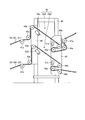
- FIG. 2 is a schematic view of the main part of a single facer equipped with the cardboard sheet defect detection device of the present embodiment.
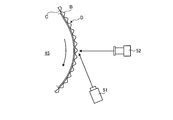
- FIG. 3 is a schematic configuration diagram illustrating a defect detection device for a corrugated cardboard sheet according to the present embodiment.
- FIG. 4 is a side view showing an arrangement configuration of an irradiation device and an imaging device for a single-sided cardboard sheet.
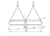
- FIG. 5 is a plan view showing an arrangement configuration of an irradiation device and an imaging device for a single-sided cardboard sheet.
- FIG. 6 is a schematic configuration diagram illustrating an imaging apparatus.
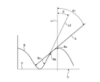
- FIG. 7 is a schematic diagram for explaining the irradiation angle of the irradiation device with respect to the center of the single-sided cardboard sheet.
- FIG. 8 is a schematic diagram showing the action of illumination light on the core of the single-sided cardboard sheet.
- FIG. 9 is a schematic diagram showing a detection position by the defect detection device for corrugated cardboard sheets.
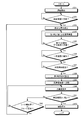
- FIG. 10 is a flowchart for explaining the image processing method.
- FIG. 11 is an explanatory diagram for explaining an image processing method.
- FIG. 12 is a schematic diagram showing a defective image of a cardboard sheet by the display device.
- FIG. 13 is a flowchart for explaining a first modification of the image processing method.
- FIG. 14 is a flowchart for explaining a second modification of the image processing method.
- FIG. 15 is a flowchart for explaining the operation of the defect detection device for cardboard sheets.
- FIG. 16 is a time chart for explaining the operation of the defect detection device for cardboard sheets.
- FIG. 17 is a graph showing the relationship between the average value, maximum value, minimum value, and determination value of the step ratio for a plurality of inspection positions.
- FIG. 1 is a schematic view showing a corrugating machine as a corrugated board manufacturing apparatus of the present embodiment.
- a corrugating machine 10 as a corrugated sheet manufacturing apparatus firstly attaches a back liner (second liner) C1 to a corrugated core B1 to provide a single-sided corrugated sheet D1. And a back liner (second liner) C2 is bonded to the corrugated core B2 to produce a single-sided cardboard sheet D2.
- the back liner C2 of the single-sided cardboard sheet D2 is bonded to the center B1 of the manufactured single-sided cardboard sheet D1, and the front liner (first liner) A is continuously bonded to the center B2 of the single-sided cardboard sheet D2.
- the manufactured double-sided cardboard sheet E is manufactured.
- seat F is manufactured by cut
- the corrugating machine 10 includes a mill roll stand 11 with a center core B1, a mill roll stand 12 with a back liner C1, a single facer 13, a bridge 14, a mill roll stand 15 with a center core B2, and a mill with a back liner C2.
- Roll stand 16 single facer 17, bridge 18, front liner A mill roll stand 19, preheater 20, glue machine 21, double facer 22, rotary 23, slitter scorer 24, and cut-off 25, a defective product discharge device 26, and a stacker 27.
- Each of the mill roll stands 11 and 15 is provided with a roll paper in which the cores B1 and B2 are formed on both sides and wound in a roll shape, and a splicer that performs a splicing between the roll papers. Is provided. When one roll paper is being fed, the other roll paper is loaded and ready for splicing. When one roll paper is low, the splicer is spliced with the other roll paper. Is done. Therefore, the paper is continuously fed from the mill roll stands 11 and 15 toward the downstream side.
- the mill roll stands 12 and 16 are each provided with roll papers in which the back liners C1 and C2 are wound in rolls on both sides, and a splicer is provided between each roll paper.
- the other roll paper is loaded and ready for splicing.
- the splicer is spliced with the other roll paper. Is done. Therefore, the paper is continuously fed from the mill roll stands 12 and 16 toward the downstream side.
- the cores B1 and B2 fed from the mill roll stands 11 and 15 and the back liners C1 and C2 fed from the mill roll stands 12 and 16 are preheated by preheaters (not shown).
- Each preheater has a heating roll to which steam is supplied, and the cores B1 and B2 and the back liners C1 and C2 are wound around the heating roll and conveyed to increase the temperature to a predetermined temperature.
- the single facer 13 forms the one-sided cardboard sheet D1 by pasting the heated core B1 into a corrugated shape and then gluing it to the tops of the steps and bonding the heated back liner C1.
- the single facer 13 is provided with a take-up conveyor obliquely upward on the downstream side in the conveyance direction, and conveys the single-sided cardboard sheet D1 formed by the single facer 13 to the bridge 14. Since the bridge 14 absorbs the speed difference between the single facer 13 and the double facer 22, the single-sided cardboard sheet D1 can be temporarily retained.
- the single facer 17 forms the single-sided cardboard sheet D2 by pasting the heated core B2 into a corrugated shape and then gluing it to the tops of the steps and bonding the heated back liner C2.
- the single facer 17 is provided with a take-up conveyor obliquely upward on the downstream side in the conveyance direction, and conveys the single-sided cardboard sheet D2 formed by the single facer 17 to the bridge 18. Since the bridge 18 absorbs the speed difference between the single facer 17 and the double facer 22, the single-sided cardboard sheet D2 can be temporarily retained.
- the mill roll stand 19 is provided with roll papers each having a front liner A wound in a roll shape on both sides, and a splicer is provided between each roll paper.
- roll papers each having a front liner A wound in a roll shape on both sides
- a splicer is provided between each roll paper.
- the other roll paper When one roll paper is being fed, the other roll paper is loaded and ready for splicing.
- the splicer is spliced with the other roll paper. Is done. Therefore, the paper is continuously fed from the mill roll stand 19 toward the downstream side.
- the preheater 20 has three preheating rolls 31, 32, 33 arranged in the vertical direction.
- the preheating roll 31 is for heating the front liner A
- the preheating roll 32 is for heating the single-sided cardboard sheet D2
- the preheating roll 33 is for heating the single-sided cardboard sheet D1.
- Each preheating roll 31, 32, 33 has a winding amount adjusting device (not shown), is supplied with steam and heated to a predetermined temperature, and has a front liner A and a single-sided cardboard sheet on its peripheral surface.
- D2 can be preheated by winding the single-sided cardboard sheet D1.
- Glue machine 21 has gluing rolls 34 and 35 arranged in the vertical direction.
- the gluing roll 34 is for gluing by contacting each top of the step of the core B2 in the single-sided cardboard sheet D2 heated by the preheating roll 32.
- the gluing roll 35 is for gluing in contact with each top of the step of the core B1 in the single-sided cardboard sheet D1 heated by the preheating roll 33.
- the single-sided cardboard sheets D1 and D2 glued by the glue machine 21 are transferred to the double facer 22 of the next process. Further, the front liner A heated by the preheating roll 31 is also transferred to the double facer 22 through the glue machine 21.
- the double facer 22 has a heating section 36 on the upstream side and a cooling section 37 on the downstream side along the traveling lines of the single-sided cardboard sheets D1 and D2 and the front liner A.
- the single-sided corrugated cardboard sheets D1 and D2 and the front liner A glued by the glue machine 21 are carried between the pressure belt and the hot plate by the heating section 36, and are cooled together in an overlapping state. It is transported towards section 37. During this transfer, the single-sided cardboard sheets D1 and D2 and the front liner A are heated while being pressurized, so that they are bonded together to form a continuous double-sided cardboard sheet E, and then naturally cooled while being conveyed.
- the double-sided cardboard sheet E manufactured by the double facer 22 is transferred to the slitter scorer 24.
- the slitter scorer 24 cuts a wide double-sided corrugated cardboard sheet E along the transport direction so as to have a predetermined width, and processes a ruled line extending in the transport direction.
- the slitter scorer 24 includes a first slitter scorer unit 38 and a second slitter scorer unit 39 that are arranged along the conveying direction of the double-faced cardboard sheet E and have substantially the same structure.
- the wide double-sided cardboard sheet E is cut by the slitter scorer 24 to form a double-sided cardboard sheet E having a predetermined width.
- the cut-off 25 is formed by cutting the double-sided cardboard sheet E cut in the transport direction by the slitter scorer 24 along the width direction into a plate-like double-sided cardboard sheet F having a predetermined length.
- the defective product discharge device 26 discharges the double-sided corrugated cardboard sheet F determined as a defective product by a defect detection device described later from the conveyance line.
- the stacker 27 stacks the double-sided corrugated cardboard sheets F determined to be non-defective products and discharges them as products to the outside of the machine.
- FIG. 2 is a schematic view of the main part of a single facer equipped with the cardboard sheet defect detection device of the present embodiment.
- the cardboard sheet defect detection device 40 is provided between the bridge 18 and the preheater 20.
- the cardboard sheet defect detection device 40 includes a first defect detection device 40A that detects defects in the single-sided cardboard sheet D1 (B1, C1) and a second defect detection device that detects defects in the single-sided cardboard sheet D2 (B2, C2). 40B, which is substantially the same configuration.
- the single-sided cardboard sheet D1 conveyed from the bridge 18 side is guided by the guide rollers 41a, 42a, 43a to reach the first defect detection device 40A, and is guided by the guide rollers 44a, 45a, 46a, 47a to the preheater 20 side. Be transported.
- the single-sided cardboard sheet D2 conveyed from the bridge 18 side is guided by the guide rollers 41b, 42b, 43b to reach the second defect detection device 40B, and is guided by the guide rollers 44b, 45b, 46b to the preheater 20 side. Be transported.
- Support plates 49 and 50 are fixed to the frame 48, guide rollers 43a and 43b are rotatably supported on the support plate 49, and guide rollers 44a, 44b, 45a, 45b, 46a, 46b, and 47a are supported on the support plate 50. It is supported rotatably. Further, imaging devices 52 a and 52 b described later are supported by the support plate 49, and irradiation devices 51 a and 51 b described later are supported by the support plate 50.
- the defect detection device 40 (40A, 40B) for cardboard sheets will be described in detail.
- FIG. 3 is a schematic configuration diagram illustrating a defect detection device for a corrugated cardboard sheet according to the present embodiment
- FIG. 4 is a side view illustrating an arrangement configuration of an irradiation device and an imaging device for a single-sided cardboard sheet
- FIG. 6 is a schematic configuration diagram illustrating the imaging apparatus.
- the cardboard sheet defect detection device 40 (40A, 40B) is a single-sided cardboard sheet D (conveyed by guide rollers 43, 44, 45, 46 with the corrugated core B facing outside. D1 and D2) are detected.
- the cardboard sheet defect detection device 40 includes an irradiation device 51 (51a and 51b), an imaging device 52 (52a and 52b), and a control device 53.
- the control device 53 includes an inspection position setting device 56, a shadow image processing device 57, a determination device 58, and a storage device 59.
- the cardboard sheet defect removing device 60 includes the cardboard sheet defect detecting device 40 and a defective product discharging device 26.
- the defect removal device 60 for corrugated cardboard includes a defect position specifying device 61 and a tracking device 62 that constitute the control device 53.
- the control device 53 is connected to a production management device 65 to which various types of information on the single-sided cardboard sheet D are input.
- the guide roller 45 is provided with a rotary encoder 66, and the control device 53 calculates the conveying speed of the single-sided cardboard sheet D based on the rotational speed of the guide roller 45 input from the rotary encoder 66.
- the guide rollers 43, 44, 45, 46 can be driven or driven to rotate, and can guide and convey the single-sided cardboard sheet D at the outer peripheral portion.
- the single-sided cardboard sheet D is formed by bonding the corrugated core B to the back liner C, and the guide roller 43 guides the single-sided cardboard sheet D with the corrugated core B facing outside. is doing.
- the irradiation device 51 irradiates parallel light toward the core B at an irradiation angle inclined by a predetermined angle set in advance with respect to the perpendicular of the single-sided cardboard sheet D.
- the imaging device 52 images the irradiation part (shadow) of the parallel light in the core B.
- the inspection position setting device 56 sets a plurality of inspection positions in the width direction of the single-sided cardboard sheet D based on the width information of the single-sided cardboard sheet D.
- the shadow image processing device 57 defines a bright portion and a dark portion along the conveyance direction of the single-sided cardboard sheet D based on the captured image captured by the imaging device 52.
- the determination device 58 determines the quality of the single-sided cardboard sheet D by comparing the length of the bright part and the length of the dark part specified by the shadow image processing device 57 with a predetermined determination value (shape determination value). It is.
- the storage device 59 stores determination values used by the determination device 58.
- the notification device 54 notifies the determination result of the determination device 58 and the like, and the display device 55 displays the determination result of the determination device 58 and the like.
- the defect position specifying device 61 is for specifying a defect position in the single-sided cardboard sheet D detected by the cardboard sheet defect detection device 40.
- the tracking device 62 tracks the defective position in the single-sided cardboard sheet D specified by the defective position specifying device 61.
- the control device 53 operates the defective product discharge device 26 based on the tracking result of the tracking device 62.
- the irradiation device 51 is disposed at a position separated from the guide roller 45 by a predetermined distance, and is fixed to the device main body (support plate 50) by a mounting bracket 71. Further, the irradiation device 51 is disposed so as to face the peripheral surface of the guide roller 45 so as to correspond to the axial length of the guide roller 45, and by the outer peripheral surface of the guide roller 45, that is, the guide roller 45.
- Parallel light can be irradiated toward the region of the full width of the single-sided cardboard sheet D to be guided. This parallel light is light that travels straight in parallel with each other, particularly when the guide roller 45 is viewed from the axial direction, without radiating the optical axes radiated toward the guide roller 45.
- the imaging device 52 is disposed at a position separated from the guide roller 45 by a predetermined distance, and is fixed to the device main body (support plate 49) by a mounting bracket 72.
- a plurality of (two in this embodiment) imaging devices 52 are provided at predetermined intervals in the axial direction of the guide roller 45.
- One image pickup device 52 is arranged on one side of the intermediate position in the axial direction of the guide roller 45 so as to face the guide roller 45, and the other image pickup device 52 is in the intermediate position in the axial direction of the guide roller 45. The other side is arranged to face the guide roller 45.
- each imaging device 52 has a field of view V1 and V2, an overlapping region V3 of the fields of view V1 and V2 is set at an intermediate position in the width direction of the single-sided cardboard sheet D, and the fields of view V1 and V2 are the single-sided cardboard sheet D. It is set beyond each end in the width direction. Therefore, each imaging device 52 can capture the entire width region of the single-sided cardboard sheet D guided by the guide roller 45 because the visual fields V1 and V2 are set to exceed the width WD of the single-sided cardboard sheet D. .
- Each imaging device 52 is a line camera, and images the irradiating portion of the mountain in the core B having a waveform shape.
- the imaging device 52 can capture an image of a plurality of pixels along the conveyance direction and the width direction of the single-sided cardboard sheet D. That is, each imaging device 52 captures an image in a region of a predetermined length in the single-sided cardboard sheet D and the entire region in the width direction at a time. Therefore, in the imaging device 52, the imaging interval is set according to the conveyance speed of the single-sided cardboard sheet D or the pitch of the peaks of the core B. In this case, as shown in FIG.
- the line camera as each imaging device 52 mainly includes an imaging sensor element (CCD imaging sensor element or CMOS imaging element) 75, a lens 76, and a control circuit (not shown). ). Incident light from the single-sided cardboard sheet D is input to the imaging sensor element 75 through the lens 76 to form an image, and the control circuit converts the amount of light in the image formation into a video signal and outputs it.
- an imaging sensor element CCD imaging sensor element or CMOS imaging element
- the imaging device (line camera) 52 is arranged on the perpendicular line of the single-sided cardboard sheet D, that is, on the line along the radial direction passing through the center of the guide roller 43.
- the sheet D is arranged on a line having an angle (irradiation angle) inclined by a predetermined angle with respect to a perpendicular line (a line along the radial direction passing through the center of the guide roller 43).
- FIG. 7 is a schematic diagram for explaining the irradiation angle of the irradiation device with respect to the core of the single-sided cardboard sheet
- FIG. 8 is a schematic diagram showing the action of illumination light on the core of the single-sided cardboard sheet
- FIG. It is the schematic showing the detection position by this defect detection apparatus.
- the single-sided cardboard sheet D has a corrugated core B attached to the back liner C, the back liner C contacts the guide roller 43, and the core B is exposed to the outside. Are transported.
- the single-sided corrugated cardboard sheet D is supported by the guide roller 45 and travels in an arc shape, but here it will be described as traveling linearly.
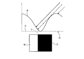
- a perpendicular line L1 of the single-sided cardboard sheet D is defined along the radial direction through the center of the guide roller 45 and the peak portion Ba of the peak of the center core B.
- the irradiation angle ⁇ 1 of the parallel light S by the irradiation device 51 is an angle with respect to the perpendicular line L1, and is set to an angle ⁇ 1 that is larger than the angle ⁇ from the perpendicular line L1 to the inclined line L2 along the slope of the mountain of the core B.
- the peak of the core B is composed of a first curved portion Bb having a convex shape outward from the peak portion Ba to the skirt portion, and a second curved portion Bc having a concave shape on the outer side. It is a tangent to the position on the most skirt side in one curve portion Bb.
- the irradiation angle ⁇ 1 of the parallel light S by the irradiation device 51 is set to an angle ⁇ 1 that is larger than the angle ⁇ from the perpendicular line L1 to the inclined line L2, a shadow of a mountain can be generated by the irradiation light.
- the irradiation apparatus 51 irradiates parallel light toward the core B at a predetermined irradiation angle ⁇ 1.
- a bright part W and a dark part G are formed.
- the boundary line J is clearly formed between the bright part W and the dark part G, and the length of the bright part W and the length of the dark part G are regulated with high accuracy. Can do.
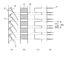
- the inspection position setting device 56 sets a plurality of inspection positions in the width direction of the single-sided cardboard sheet D based on the width dimension of the single-sided cardboard sheet D input from the production management device 65. As shown in FIG. 9, the imaging device 52 captures an image M in the entire area in the width direction over a predetermined length with respect to the single-sided cardboard sheet D. The inspection position setting device 56 sets a plurality of inspection positions N1, N2, N3... N27, N28 for the width WD of the single-sided cardboard sheet D.
- the inspection position setting device 56 sets an uninspected area M0 at each end in the width direction of the single-sided cardboard sheet D, sets an inspection area M1 between the uninspected areas M0 at each end, A plurality of inspection positions N1, N2, N3... N27, N28 are set in M1 at predetermined intervals. That is, in the present embodiment, the pass / fail judgment is not performed over the entire width direction of the single-sided cardboard sheet D, but the pass / fail judgment is made at a plurality of positions in the width direction of the single-sided cardboard sheet D. It is desirable that the length in the width direction of the uninspected region M0 is set to be shorter than the interval between the inspection positions N1, N2, N3... N27, N28.
- the single-sided cardboard sheet D may meander so as to shift in the width direction during conveyance, and an uninspected region M0 is set at each end in the width direction according to the meandering amount of the single-sided cardboard sheet D.
- the length in the width direction of the uninspected area M0 is set according to the configuration of the corrugating machine 10 itself, the conveyance accuracy, and the like.
- a plurality of inspection positions N1, N2, N3... N27, N28 are set at equal intervals in the width direction in the inspection region M1.
- the inspection positions N1, N2, N3... N27, N28 are not limited to a configuration in which the inspection positions N1, N2, N3.
- the single-sided cardboard sheet D is likely to be defective on the end side in the width direction, a plurality of inspection positions N1, N2, N3... N27, N28 interval is narrowed (setting density is increased), and intervals between the plurality of inspection positions N1, N2, N3... N27, N28 on the center side in the width direction of the single-sided cardboard sheet D are set large (setting density is decreased). You may make it do. Further, even if the interval between the inspection positions N1, N2, N3... N27, N28 in a region where defects are likely to occur other than the end portion in the width direction in the single-sided cardboard sheet D is narrowed (set density is increased). Good.
- the shadow image processing device 57 defines the bright portion W and the dark portion G from the shadow of each mountain of the core B from the captured image of the imaging device 52.
- the imaging device (line camera) 52 causes the shadow of one peak in the corrugated core B to be one pixel along the conveyance direction of the single-sided cardboard sheet D and along the width direction of the single-sided cardboard sheet D.
- the shaded image processing device 57 combines a plurality of images of 1 pixel ⁇ multiple pixels along the conveyance direction of the single-sided cardboard sheet D, so that a plurality of continuous bright portions W in a predetermined length of the single-sided cardboard sheet D are obtained.
- dark part G is defined.
- the inspection position setting device 56 sets a plurality of inspection positions in the width direction of the single-sided cardboard sheet D
- the shadow image processing device 57 sets the bright part W and dark part G of the single-sided cardboard sheet D by a predetermined length.
- the bright part W and the dark part G are added in the width direction of the single-sided cardboard sheet D to define the bright part W and the dark part G, respectively, at the inspection positions N1, N2, N3. .
- the determination device 58 determines the quality of the single-sided cardboard sheet D by comparing the length of the bright portion W and the length of the dark portion G defined by the shadow image processing device 57 with the determination value. In this case, the determination device 58 calculates the step ratio by dividing the length of the dark part G by the length of the bright part W, and compares the step ratio with a determination value to determine pass / fail.
- the step ratio may be calculated by dividing the length of the bright part W by the length of the dark part G, or by dividing the length of the dark part G or the length of the bright part W by the total length thereof. A step ratio may be calculated.
- the determination device 58 performs the pass / fail judgment, and the pass / fail judgment of the bright part W and the pass / fail judgment of the dark part G are continued. It is done.
- the standard value of the shape of the single-sided corrugated cardboard sheet D (design value of the height and pitch of the corrugated mountain) is set according to the specifications (size, type of flute, etc.) of the double-faced cardboard sheet F to be manufactured.
- a determination reference value is set in advance by experiments or the like according to the shape of the peak of the core B in the single-sided cardboard sheet D set to the standard value. To do.
- this determination reference value may be used as the determination value, it is desirable to set the determination reference range of the double-sided corrugated cardboard sheet F that is determined to be non-defective by taking into account manufacturing errors and detection errors.
- the determination area is set by adding a predetermined margin to the determination reference value. That is, if the ratio between the length of the bright portion W and the length of the dark portion G (step ratio) obtained by processing by the shadow image processing device 57 is within the determination region, the single-sided cardboard sheet D is determined to be non-defective. If it is not within the region, the single-sided cardboard sheet D is determined to be defective.
- the determination value (determination area) is set for each type of single-sided cardboard sheet D (type of center core B) and stored in the storage device 59.
- the shape of the shadow is different, so the length of the bright portion W and the length of the dark portion G are different. Therefore, a plurality of types of determination values (determination areas) corresponding to the shape of the core B are set.
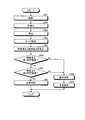
- FIG. 10 is a flowchart for explaining the image processing method
- FIG. 11 is an explanatory diagram for explaining the image processing method
- FIG. 12 is a schematic diagram showing a defective image of the cardboard sheet by the display device.
- step S11 the captured shadow image of the core B is projected. That is, as shown in FIGS. 11 (a), 11 (b), and 11 (c), the imaging data of the bright portion W and the dark portion G is obtained by using a shadow image in which a plurality of images of 1 pixel ⁇ multiple pixels are captured and arranged in the transport direction. Addition is performed in the width direction of the single-sided cardboard sheet D, and the added luminance is calculated. Returning to FIG. 10, in step S12, noise is removed by smoothing the added luminance in the transport direction. In step S13, as shown in FIG. 11 (d), the difference in the added luminance of pixels adjacent in the transport direction is taken, that is, the difference is obtained. Returning to FIG.
- step S14 since the difference value is large at the edges of the bright part W and the dark part G, the peak value P at which the difference value is large is extracted.
- step S15 the length W1 of the bright part W and the length G1 of the dark part G are calculated.
- step S16 the ratio (step ratio) between the length W1 of the bright part W and the length G1 of the dark part G is calculated as follows.
- Step density ratio dark part G length G1 / light part W length W1
- step S17 the ratio between the length W1 of the bright portion W and the length G1 of the dark portion G, that is, the step ratio is compared with the determination region, and it is determined whether the step ratio is within the determination region. To do.
- step S17 If it is determined in step S17 that the step ratio is within the determination region (Yes), the process proceeds to step S18 as a non-defective product, and it is normally determined that one peak of the core B is a good product. . On the other hand, if it is determined in step S17 that the step ratio is not within the determination region (No), the process proceeds to step S19 as a defective product. In step S19, it is determined that one peak of the core B is a defective product. In step S20, the notification device 54 issues an alarm (lamp or alarm sound). In step S21, the display device is displayed. 55 displays an image of the defective product on the display.
- the display device 55 displays an image of the single-sided cardboard sheet D imaged by the imaging device 52, and displays the position of the peak of the core B determined to be defective with a circle. To do. Then, the storage device 59 stores an image of the core B determined to be defective.
- the single-sided corrugated cardboard sheet D in which the crest of the core B is determined to be a defective product often has poor bonding due to insufficient heating, and at this time, control is performed to reduce the conveyance speed of the single-sided cardboard sheet D. May be executed.
- step S22 the defective double-sided corrugated cardboard sheet F including the defective crest is discharged from the conveyance line to the outside.
- the position where the defective portion is generated is tracked, and the double-sided cardboard sheet F including the defective portion is Exclude.
- the single-sided corrugated cardboard sheet D double-sided corrugated cardboard sheets E and F
- the single-sided corrugated cardboard sheet D is transported from the imaging time (time) of the peak of the core B by the imaging device 52 to the defective judgment time (time) by the determination device 58.
- the defective position of the mountain of the core B is specified based on the cardboard sheet conveyance distance.
- the tracking device 62 tracks the defective position of the crest of the core B that moves as time passes, and the time (time) at which the cut double-sided corrugated cardboard sheet F including the defective position reaches the defective product discharge device 26 is detected. presume. Based on the tracking result of the tracking device 62, the control device 53 operates the defective product discharge device 26 when the double-sided cardboard sheet F including the defective position reaches the defective product discharge device 26.
- the defective double-sided cardboard sheet F discharged from the transport line is sent to a shredder by a transport device (not shown) and cut.
- the defective double-sided corrugated cardboard sheet F discharged from the transport line has not only a stepped defect in the core B but also a bonding defect or a paper splice. Therefore, a switching device may be provided in the transport device, and only the double-faced corrugated cardboard sheet F determined to be a stepped mountain defect in the core B may be stored without being sent to the shredder by the transport device. That is, later, the operator can visually recognize the double-sided cardboard sheet F that has been determined to have a stepped defect in the core B.
- the determination device 58 compares the ratio of the length of the dark part G and the length of the bright part W (step ratio) with the determination value (determination area) to determine whether the single-sided cardboard sheet D is good or bad. Although it comprised so that it might determine, it is not limited to this structure.
- FIG. 13 is a flowchart for explaining a first modification of the image processing method
- FIG. 14 is a flowchart for explaining a second modification of the image processing method.
- the captured shadow image of the core B is projected in step S51.
- step S52 noise is removed by smoothing the added luminance in the conveyance direction.
- step S53 the difference of the added luminance of pixels adjacent in the transport direction is taken, that is, the difference is obtained.
- step S54 since the difference value becomes large at the edges of the bright part W and the dark part G, the peak value P at which the difference value becomes large is extracted.
- step S55 the length W1 of the bright part W (or the length G1 of the dark part G) is calculated.
- step S56 the length W1 of the bright part W is compared with the bright part determination area (or the length G2 of the dark part G is compared with the dark part determination area), and the length W1 of the bright part W is determined as the bright part. Determine if it is in the region.
- the process proceeds to step S57 as being non-defective, and it is determined that one peak of the core B is non-defective. To do.
- step S58 it is determined that one peak of the core B is defective.
- step S59 the defective double-sided corrugated cardboard sheet F including the defective peak is discharged from the conveyance line to the outside. .
- the captured shadow image of the core B is projected in step S61.
- step S62 noise is removed by smoothing the added luminance in the transport direction.
- step S63 the difference in the added luminance of pixels adjacent in the transport direction is taken, that is, the difference is obtained.
- step S64 since the difference value increases at the edges of the bright part W and the dark part G, the peak value P at which the difference value increases is extracted.
- step S65 the length W1 of the bright part W and the length G1 of the dark part G are calculated.
- step S66 the length W1 of the bright part W is compared with the bright part determination area to determine whether the length W1 of the bright part W is within the bright part determination area.
- the process proceeds to step S67 as a non-defective product.
- step S67 the length G2 of the dark part G is compared with the dark part determination area, and it is determined whether or not the length G1 of the dark part G is within the dark part determination area.
- step S68 if it is determined that the length G1 of the dark part G is within the dark part determination region, the process proceeds to step S68 as being non-defective, and here, it is determined that one mountain of the core B is non-defective.
- step S66 if it is determined in step S66 that the length W1 of the bright portion W is not within the bright portion determination area, the process proceeds to step S69 as a defective product. If it is determined in step S67 that the length G1 of the dark part G is not within the dark part determination area, the process proceeds to step S69 as a defective product. In step S69, it is determined that one peak of the core B is a defective product, and in step S70, the defective double-sided corrugated cardboard sheet F including the defective peak is discharged from the conveyance line to the outside.
- the determination device 58 compares the step ratio of the core B in the single-sided cardboard sheet D with the determination value (determination area) to determine whether the single-sided cardboard sheet D is acceptable. Judgment.
- the normal inspection mode and the high-precision inspection mode can be selected and switched as the inspection mode for inspecting the single-sided cardboard sheet D.
- FIG. 15 is a flowchart for explaining the operation of the cardboard sheet defect detection device
- FIG. 16 is a time chart for explaining the operation of the cardboard sheet defect detection device.
- the determination device 58 compares the captured image captured by the imaging device 52 with the shape determination value of the core B, and determines the quality of the single-sided cardboard sheet D.
- the shape determination value of the core B is configured by a first determination value for the normal inspection mode and a second determination value for the high-precision inspection mode, and the determination device 58 sets the first determination value. It has a value setting unit 58a and a second determination value setting unit 58b for setting a second determination value.
- the first determination value is a constant value set in advance
- the second determination value is an individual value set based on a captured image captured by the imaging device 52 after the determination based on the first determination value is started. 58 is switchable between a first determination value and a second determination value.
- the determination device 58 determines the step ratio and the shape determination value at a plurality of inspection positions N1, N2, N3... N27, N28 in the width direction of the single-sided cardboard sheet D set by the inspection position setting device 56.
- the quality of the single-sided cardboard sheet D is determined by comparing each.
- the first determination value is set based on the determination reference value of the shape of the peak of the core B in the single-sided cardboard sheet D before the start of the operation of the corrugating machine 10, and each inspection position N1, N2 , N3... N27, N28 are set as constant values.
- the second determination value is set based on the step ratio of the single-sided corrugated cardboard sheet D for which the determination device 58 has determined the non-defective product using the first determination value, and each inspection position N1, N2, N3,. ..Set as individual values for each of N27 and N28.
- the first determination value setting unit 58a sets a first determination value by adding and subtracting preset margin values a and b to the determination reference value. That is, the first determination value setting unit 58a sets the first upper limit value by adding the margin value a to the determination reference value, and sets the first lower limit value by subtracting the margin value b from the determination reference value. Therefore, in the normal inspection using the first determination value by the determination device 58, the detected step ratio is the first upper limit value at each inspection position N1, N2, N3... N27, N28 of the single-sided cardboard sheet D. When it is in the determination region between the first lower limit value, it is determined that the single-sided cardboard sheet D is a non-defective product.
- the second determination value setting unit 58b uses each step position N1, N2, N3... N27 using the step ratio of the single-sided corrugated cardboard sheet D determined by the determination device 58 using the first determination value. , N28, the second judgment value is set by adding and subtracting preset margin values ⁇ and ⁇ to the average value of a plurality of data (step ratio). That is, the second determination value setting unit 58b sets the second upper limit value by adding the margin value ⁇ to the average value of the plurality of data (step mountain ratio), and sets the margin from the average value of the plurality of data (step mountain ratio). The value ⁇ is subtracted to set the second lower limit value.
- the detected step ratio is the second upper limit value at each inspection position N1, N2, N3... N27, N28 of the single-sided cardboard sheet D.
- the second lower limit value it is determined that the single-sided cardboard sheet D is a non-defective product.
- the method of setting the second determination value is not limited to the method described above.
- the second determination value setting unit 58b uses each step position N1, N2, N3,... N27 using the step ratio of the single-sided corrugated cardboard sheet D that the determination device 58 has determined to be non-defective using the first determination value.
- the second determination value may be set by adding and subtracting preset margin values ⁇ 1 and ⁇ 2 to the maximum and minimum values of a plurality of data (step ratio). That is, the second upper limit value is set by adding the margin value ⁇ 1 to the maximum value of the plurality of data (step ratio), and the margin value ⁇ 1 is subtracted from the minimum value of the plurality of data (step ratio). Then, the second lower limit value is set.
- the second determination value setting unit 58b uses each step position N1, N2, N3,... Using the step ratio of the single-sided corrugated cardboard sheet D determined by the determination device 58 using the first determination value.
- a standard deviation of a plurality of data (step ratio) at N27 and N28 may be calculated, and this standard deviation may be used as a margin value. That is, the second upper limit value and the second lower limit value are set by adding the standard deviation as a margin value to the average value of a plurality of data (step ratio).
- the standard deviation multiplied by a correction coefficient (for example, natural numbers such as 1, 2, 3,...) May be defined as the determination region.
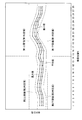
- FIG. 17 is a graph showing the relationship between the average value, the maximum value, the minimum value, and the determination value of the step ratio for a plurality of inspection positions.
- the inspection results (corrugated mountain) in a predetermined length in the conveyance direction of the single-sided cardboard sheet D
- the average value of the ratio varies vertically in the width direction of the single-sided cardboard sheet D.
- the average value of the step ratio is data of the single-sided corrugated cardboard sheet D determined to be a non-defective product, and should be a constant value.
- the convergence difference or distortion of the lens 76 in the image pickup device 52, and the passage of light to the lens 76 It varies depending on the position.
- the determination device 58 determines the quality of the single-sided cardboard sheet D using the first determination value, and the inspection data of the single-sided cardboard sheet D determined as non-defective product ( The second determination value is set based on the step ratio.
- the first upper limit value as the first determination value is set by adding the margin value a to the determination reference value
- the first lower limit value is set by subtracting the margin value b from the determination reference value. Therefore, the first upper limit value and the first lower limit value are constant values regardless of the inspection positions N1, N2, N3... N27, N28.
- the design value is the specification (size, type of flute, etc.) of the double-faced cardboard sheet F to be manufactured.
- the second upper limit value as the second determination value is set by adding the margin value ⁇ to the average value of the plurality of step ratios at each of the inspection positions N1, N2, N3... N27, N28.
- the 2 lower limit value is set by subtracting the margin value ⁇ from the average value of the plurality of step ratios at each of the inspection positions N1, N2, N3... N27, N28. Therefore, the second upper limit value and the second lower limit value are individual values that are different at the respective inspection positions N1, N2, N3... N27, N28.
- a margin value ⁇ 1 is added to the maximum value of the plurality of step ratios at each of the inspection positions N1, N2, N3...
- N27, N28 to set a second upper limit value, and each of the inspection positions N1, N2, N3. ... Even when the second lower limit value is set by subtracting the margin value ⁇ 1 from the minimum value of the plurality of step ratios at N27 and N28, the second upper limit value and the second lower limit value are Different values are obtained at the positions N1, N2, N3... N27, N28.
- the second determination value setting unit 58b of the determination device 58 reaches the second determination value setting speed set in advance and maintains the constant speed at the conveyance speed of the single-sided cardboard sheet D.
- the second determination value is set after elapse of a predetermined time set in advance.
- the corrugating machine 10 uses the back liner C (C1, C2), the core B (B1, B2), and the front liner A (A1, A2) to be used.
- the double-sided cardboard sheets F are continuously manufactured.
- the corrugating machine 10 continuously manufactures the double-sided cardboard sheet F by exchanging and switching the used cardboard rolls when the height of the double-sided cardboard sheet F to be manufactured is changed.
- the determination device 58 switches from the high-precision inspection using the second determination value to the normal inspection using the first determination value, and the normal inspection using the first determination value.
- the second determination value is set in the same manner as described above. At this time, the switching from the second determination value to the first determination value by the determination device 58 is performed when the splicing portion of the single-sided cardboard sheet D (D1, D2) passes through the imaging position by the imaging device 52.
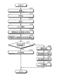
- the cardboard sheet defect detection device 40 determines whether or not the conveyance speed of the single-sided cardboard sheet D has reached a preset inspection speed.
- the control device 53 calculates the conveyance speed of the single-sided cardboard sheet D based on the rotation speed of the guide roller 45 input from the rotary encoder 66. Here, if it is determined (No) that the conveyance speed of the single-sided cardboard sheet D has not reached the inspection speed, this process is repeated.
- the inspection position in the width direction of the single-sided cardboard sheet D is set in step S33. That is, the inspection position setting device 56 sets an uninspected region M0 at each end in the width direction of the single-sided cardboard sheet D based on the width dimension of the single-sided cardboard sheet D input from the production management device 65, and A plurality of inspection positions N1, N2, N3... N27, N28 are set in the inspection area M1 between the uninspected areas M0 (see FIG. 9).
- step S34 the determination device 58 sets the first determination value set in advance by the first determination value setting unit 58a.
- a normal inspection of the single-sided cardboard sheet D is performed based on the determination value.
- inspection data is stored in the storage device 59.
- step S35 it is determined whether or not the conveyance speed of the single-sided cardboard sheet D has reached the second determination value calculation speed.
- the normal inspection in step S34 is continued.
- step S36 it is determined in step S36 whether the conveyance speed of the single-sided cardboard sheet D is maintained at a constant speed. To do. Here, if it is determined (No) that the conveyance speed of the single-sided cardboard sheet D is not maintained at a constant speed, this process is repeated. On the other hand, if it is determined that the conveyance speed of the single-sided cardboard sheet D is maintained at a constant speed (Yes), a predetermined time set in advance after the conveyance speed of the single-sided cardboard sheet D is maintained at a constant speed in step S37. Determine whether or not.
- a second determination value is set in step S38.
- the second determination value setting unit 58b uses the step ratio of the single-sided corrugated cardboard sheet D determined to be non-defective in the normal inspection, and uses a plurality of data at each inspection position N1, N2, N3... N27, N28 ( The second determination values (second upper limit value, second lower limit value) are calculated by adding and subtracting the margin values ⁇ and ⁇ to the average value of the step ratio).
- step S39 the determination device 58 switches the determination value from the first determination value to the second determination value.
- step S40 the determination device 58 sets the second determination value to the second determination value. Based on this, high-precision inspection of the single-sided cardboard sheet D is performed.
- step S41 it is determined whether or not the conveyance speed of the single-sided cardboard sheet D has decreased to a speed lower than the inspection speed.
- the control device 53 determines whether the sheet-width cardboard sheet D sheet width change command or It is determined whether a flute change command is input.
- the production management device 65 knows the number of sheets of double-sided corrugated cardboard sheets F having a predetermined width or a predetermined flute shape, and the control device 53 receives the timing for changing the sheet width or flute shape from the production management device 65.
- step S40 if it is determined that there is no sheet width change or flute change of the single-sided cardboard sheet D (No), the high-precision inspection in step S40 is continued. On the other hand, if it is determined that there is a sheet width change or flute change of the single-sided cardboard sheet D (Yes), the process returns to step S33, and after the sheet width change or flute change, the width-direction inspection on the single-sided cardboard sheet D after change Set the position again. And the process from step S34 to step S41 is performed similarly to the above-mentioned.
- step S41 if it is determined in step S41 that the conveyance speed of the single-sided cardboard sheet D has decreased to a speed lower than the inspection speed (Yes), the inspection of the single-sided cardboard sheet D by the defect detection device 40 for the cardboard sheet is terminated.
- step S43 the operation of the corrugating machine 10 is stopped.
- the conveyance speed of the single-sided cardboard sheet D exceeds the second determination value calculation speed, and is maintained at a constant speed at time t4.
- Calculation of the second determination value is started at a time t5 when a predetermined time has elapsed after the conveyance speed of the single-sided cardboard sheet D is maintained at a constant speed.
- the second determination value is set at time t6, the determination value is switched from the first determination value to the second determination value, and high-precision inspection of the single-sided cardboard sheet D using the second determination value is started.
- N27, N28 on the single-sided cardboard sheet D are set again, and the conveyance speed of the single-sided cardboard sheet D exceeds the second determination value calculation speed, and is constant for a predetermined time.
- the calculation of the second determination value is started at time t10 maintained at.
- the determination value is switched from the first determination value to the second determination value, and high-precision inspection of the single-sided cardboard sheet D using the second determination value is started.
- N27, N28 on the single-sided cardboard sheet D are set again, and the conveyance speed of the single-sided cardboard sheet D exceeds the second determination value calculation speed, and is constant for a predetermined time.
- the calculation of the second determination value is started at time t15 maintained at.
- the determination value is switched from the first determination value to the second determination value, and high-precision inspection of the single-faced cardboard sheet D using the second determination value is started.
- the cardboard sheet defect detection apparatus is a cardboard sheet defect detection apparatus 40 that detects a defect of the corrugated core B that is attached to the back liner C.
- An imaging device 52 that images the core B of the cardboard sheet D
- an inspection position setting device 56 that sets a plurality of inspection positions in the width direction of the single-sided cardboard sheet D based on the width information of the single-sided cardboard sheet D
- an imaging device 52 Is provided with a determination device 58 that determines the quality of the single-sided cardboard sheet D based on the captured images at a plurality of inspection positions set by the inspection position setting device 56 from the captured images taken by the camera.
- a plurality of inspection positions in the width direction of the single-sided cardboard sheet D are set based on the width information of the single-sided cardboard sheet D, and the single-sided cardboard sheet is based on the captured images taken by the imaging device 52 at the plurality of inspection positions. Since the quality of D is determined, the determination device 58 determines the quality of the single-sided cardboard sheet D based on the photographed image at the optimum inspection position in the width direction of the single-sided cardboard sheet D. As a result, it is possible to improve the defect detection accuracy of the single-sided cardboard sheet D by reducing the uninspected area at the end of the single-sided cardboard sheet D.
- the inspection position setting device 56 sets an uninspected region M0 at each end in the width direction of the single-sided cardboard sheet D, and between the uninspected regions M0 at each end.
- a plurality of inspection positions are set at predetermined intervals in the inspection region M1 to be set. Therefore, first, an uninspected area M0 is set at each end in the width direction of the single-sided cardboard sheet D, and then a plurality of inspection positions are set in the inspection area M1 set between the uninspected areas M0. Regardless of the width dimension of the single-sided cardboard sheet D, an uninspected area M0 having a desired dimension can be set, and expansion of the uninspected area M0 after the width change of the single-sided cardboard sheet D can be suppressed.
- a plurality of inspection positions are set at equal intervals in the inspection area M1. Therefore, it is possible to suppress the variation in the quality determination accuracy of the single-sided cardboard sheet D.
- the setting density of a plurality of inspection positions on each end side in the width direction of the single-sided cardboard sheet D is set to a plurality of inspection positions on the center side in the width direction of the single-sided cardboard sheet D. It is set higher than the density. Therefore, by narrowing the interval between the plurality of inspection positions on each side in the width direction of the single-sided corrugated cardboard sheet D and widening the interval between the plurality of inspection positions on the center side, an end portion that is likely to cause poor bonding or the like.
- the side can be inspected in detail, and the pass / fail judgment accuracy of the single-sided cardboard sheet D can be improved.
- a notification device 54 is provided for notifying the occurrence of a defect when the determination device 58 determines the defect of the single-sided cardboard sheet D. Therefore, when the defect occurrence of the single-sided corrugated cardboard sheet D is determined, the occurrence of the defect is notified, so that the operator can be notified of the occurrence of the defect and an early countermeasure can be taken.
- the notification device 54 issues an alarm. Therefore, by issuing an alarm when the defect of the single-sided cardboard sheet D is determined, it is possible to accurately notify the operator of the occurrence of the defect.
- a display device 55 for displaying an image of the single-sided cardboard sheet D determined by the determination device 58 is provided. Therefore, when the defect of the single-sided cardboard sheet D is determined, the operator recognizes the form of the defect from the image on the display device 55 by displaying the image of the single-sided cardboard sheet D determined to be defective on the display device 55. can do.
- a storage device 59 for storing the image of the single-sided cardboard sheet D determined by the determination device 58 is provided. Therefore, when it is determined that the single-sided cardboard sheet D is defective, the image of the single-sided cardboard sheet D determined to be defective is stored in the storage device 59, so that the operator can use the image stored in the storage device 59 later. The form of failure can be recognized.
- the inspection position setting device 56 determines whether the single-sided cardboard sheet D is in the width direction based on the width information of the single-sided cardboard sheet D. A plurality of inspection positions are reset. Therefore, every time the width dimension of the single-sided cardboard sheet D is changed, a plurality of inspection positions in the width direction of the single-sided cardboard sheet D are reset, so that the inspection position always optimum for the width dimension of the single-sided cardboard sheet D The quality of the single-sided cardboard sheet D is determined based on the photographed image at.
- the determination device 58 compares the photographed image captured by the image capturing device 52 with the shape determination value of the core B and determines the quality of the single-sided cardboard sheet D.
- the shape determination value a first determination value that is set in advance and a second determination value that is set based on a captured image captured by the imaging device 52 after the start of the determination based on the first determination value are provided. 58 can switch between the first determination value and the second determination value.
- the determination device 58 determines whether the captured image and the first determination value are the same. Are compared to determine whether the single-sided cardboard sheet D is good or bad, and after the start of the determination based on the first determination value, the second determination value is set based on the captured image captured by the imaging device 52, and the second determination value is set. Then, the first determination value is switched to the second determination value, and the quality of the single-sided cardboard sheet D is determined by comparing the captured image with the second determination value. As a result, it is possible to improve the defect detection accuracy of the single-sided cardboard sheet D by performing the quality determination of the single-sided cardboard sheet D using the second determination value corresponding to the characteristics of the imaging device or the like.
- the determination device 58 compares the captured images at the plurality of inspection positions in the width direction of the single-sided cardboard sheet D with the shape determination values set for the plurality of inspection positions.
- the quality of the single-sided cardboard sheet D is determined.
- the first determination value is set to a constant value corresponding to a plurality of inspection positions
- the second determination value is set to individual values corresponding to the plurality of inspection positions.
- the determination device 58 sets a constant value corresponding to a plurality of inspection positions as the first determination value, and sets a second determination value as an individual value corresponding to the plurality of inspection positions, so that the single-sided cardboard sheet is set in advance.
- the first determination value can be easily set based on the design value of D, and the second determination value can be set at a plurality of inspection positions by using the result of pass / fail determination of the single-sided cardboard sheet D based on the first determination value. Accordingly, it can be set with high accuracy.
- the determination device 58 sets a second determination value based on a photographed image that has determined a non-defective product using the first determination value. Accordingly, since the second determination value is set based on a non-defective photographed image, the second determination value can be set with high accuracy corresponding to the characteristics of the imaging device 52 and the like, and the single-sided cardboard sheet D is defective. The detection accuracy can be improved.
- the determination device 58 sets the second determination value based on the average value of a plurality of photographed images that are determined to be non-defective using the first determination value. Therefore, the second determination value can be set with high accuracy corresponding to the characteristics of the imaging device 52 and the like.
- the second determination value is obtained by adding a preset margin value to the average value of a plurality of photographed images in which the determination device 58 has determined the non-defective product using the first determination value. It is set. Therefore, the second determination value can be set with high accuracy corresponding to the characteristics of the imaging device 52 and the like.
- the determination device 58 sets the second determination value based on the maximum value or the minimum value of a plurality of photographed images that are determined to be non-defective using the first determination value. Therefore, the region of the second determination value can be set with high accuracy corresponding to the characteristics of the imaging device 52 and the like.
- the determination device 58 adds a preset margin value to the maximum value or the minimum value of a plurality of photographed images for which non-defective products have been determined using the first determination value, and the second.
- the judgment value is set. Therefore, the region of the second determination value can be set with high accuracy corresponding to the characteristics of the imaging device 52 and the like.
- the step ratio at a predetermined length in the conveyance direction of the single-sided cardboard sheet D.
- the average value varies in the vertical direction in the width direction of the single-sided cardboard sheet D due to the characteristics of the imaging device 52 (convergence difference and distortion of the lens 76, light passing position with respect to the lens 76, etc.). Therefore, the determination device 58 adds and subtracts the margin values ⁇ and ⁇ to the average value of the staircase ratio of the single-sided corrugated cardboard sheet D determined to be non-defective using the first determination value, and thereby adds the second upper limit value and the second lower limit value.
- the determination device 58 adds and subtracts the margin values ⁇ 1, ⁇ 1 to and from the maximum value and the minimum value of the step ratio of the single-sided corrugated cardboard sheet D determined to be non-defective using the first determination value.
- a second lower limit value is set.
- the determination using the second upper limit value and the second lower limit value is an individual value that differs at each of the inspection positions N1, N2, N3... N27, N28 along the average value, the maximum value, and the minimum value. Therefore, the area determined as non-defective is narrower than the determination using the first upper limit value and the first lower limit value, and only a high-quality single-sided cardboard sheet D can be determined as non-defective.
- the single-sided cardboard sheet D erroneously determined as a defective product can be determined as a non-defective product.
- the second determination value is set after the conveyance speed of the single-sided cardboard sheet D reaches the preset second determination value setting speed and is maintained at a constant speed. ing. Accordingly, the imaging device 52 images the single-sided cardboard sheet D that is conveyed at a constant speed, optimizes a plurality of captured images captured by the imaging device 52, and improves the defect detection accuracy of the single-sided cardboard sheet D. Can be planned.
- the second determination value is set after a predetermined time has elapsed since the conveyance speed of the single-sided cardboard sheet D is maintained at a constant speed. Accordingly, the imaging device 52 images the core B in a state where the conveyance state of the single-sided cardboard sheet D is stable, and the defect detection accuracy of the single-sided cardboard sheet D can be improved by optimizing the captured image. .
- the determination device 58 switches from the second determination value to the first determination value, and images are taken after the determination by the first determination value is started.
- the second determination value is set based on the captured image captured by the device 52. Therefore, when the type of the single-sided cardboard sheet D is changed, the determination device 58 switches from the pass / fail determination using the second determination value to the pass / fail determination using the first determination value, and sets the second determination value again.
- the quality determination of the single-sided cardboard sheet D can be continuously performed, and an optimal second determination value according to the type of the single-sided cardboard sheet D can be set.
- the defect detection device for a corrugated cardboard sheet In the defect detection device for a corrugated cardboard sheet according to the present embodiment, switching from the second determination value to the first determination value by the determination device 58 is performed when the paper splicing portion of the single-sided cardboard sheet D passes the image pickup position by the image pickup device 52. . Accordingly, since the paper splicing portion of the single-sided cardboard sheet D is determined to be defective by another defect detection device, when the paper splicing portion of the single-sided cardboard sheet D passes the imaging position, By switching to 1 determination value, it is possible to suppress the occurrence of undetected defective products and false detection of non-defective products.
- the irradiation device 51 that irradiates the parallel light S toward the core B at an irradiation angle ⁇ 1 inclined by a predetermined angle with respect to the perpendicular L1 of the single-sided cardboard sheet D.
- an imaging device 52 that images the irradiation part of the parallel light S in the core B, and a bright part W and a dark part G along the conveyance direction of the single-sided cardboard sheet D based on the captured image captured by the imaging device 52.
- a device 58 is provided.
- the imaging device 52 images the irradiation part of the parallel light S in the core B and shadows it.
- the image processing device 57 defines the bright portion W and the dark portion G along the conveyance direction of the single-sided cardboard sheet D based on the photographed image, and the determination device 58 determines the length W1 of the bright portion W and the length of the dark portion G.
- the quality of the single-sided cardboard sheet D is determined by comparing G1 with a determination value (determination area).
- the defect of the core B that is, the defect of the double-sided cardboard sheet F is detected based on the lengths W1 and G1 of the bright part W and the dark part G formed by the shadow of the peak of the core B having the waveform shape. It will be. Therefore, it is possible to detect crushing failure, height failure, length failure, and the like of the core B, and it is possible to detect the failure of the double-faced corrugated cardboard sheet F due to deformation of the corrugated peak in the core B with high accuracy. .
- the shadow image processing device 57 defines the bright portion W or dark portion G along the conveyance direction of the single-sided cardboard sheet D based on the photographed image, and the determination device 58 determines the length W1 or dark portion G of the bright portion W.
- the quality of the single-sided cardboard sheet D may be determined by comparing the length G1 with the determination values (bright portion determination value, dark portion determination value). Since the number of inspection positions of the single-sided cardboard sheet D by the defect detection device 40 depends on the processing capability of the determination device 58, the determination device 58 can determine which of the length W1 of the bright portion W and the length G1 of the dark portion G.
- the quality of the single-sided cardboard sheet D is judged by comparing the judgment value (bright part judgment value, dark part judgment value), the number of inspection positions of the single-sided cardboard sheet D by the defect detection device 40 may be increased. It is possible to detect a defect of the double-faced cardboard sheet F with high accuracy.
- the cardboard sheet defect detecting device 40 and the double-sided cardboard sheet cut into a predetermined length including the defective portion detected by the cardboard sheet defect detecting device 40.
- a defective product discharge device 26 for discharging F is provided.
- the defect detection device 40 of the corrugated cardboard sheet has a defect in the core B based on the lengths W1 and G1 of the bright part W and the dark part G formed by the shadow of the peak of the core B having a corrugated shape.
- a failure of the sheet F is detected. Therefore, it is possible to detect crushing failure, height failure, length failure, etc. of the core B, and to detect the failure of the double-faced corrugated cardboard sheet F due to deformation of the corrugated peak in the core B with high accuracy. Only the double-sided cardboard sheet F can be conveyed.
- the single facers 13 and 17 manufacture the single-sided cardboard sheet D by bonding the back liner C to the corrugated core B, and the double facer 22 has the front liner A on the center B side of the single-sided cardboard sheet D.
- the cardboard sheet defect removing device 60 detects a defect of the single-sided cardboard sheet D, and the defective product discharging device 26 discharges the double-sided cardboard sheet F cut to a predetermined length including the defective portion from the conveying line and removes it. To do. Therefore, the defect detection accuracy of the single-sided cardboard sheet D can be improved by reducing the uninspected area M0 at the end of the single-sided cardboard sheet D.
- the cardboard sheet defect detection device 40 determines that the single-sided cardboard sheet D is defective, the conveyance speed of the single-sided cardboard sheet D is reduced. Therefore, when the back liner C (C1, C2) is bonded to the corrugated core B (B1, B2) of the single facers 13, 17, the corrugated core B (B1, B2) is glued. After that, the back liner C (C1, C2) is pressed and then heated and bonded to produce the single-sided cardboard sheet D (D1, D2).
- seat D can be increased, and bonding failure generation
- the determination device 58 determines the ratio of the length of the dark portion G to the length of the bright portion W (step density), the length W1 of the bright portion W, and the length G1 of the dark portion G as the bright portion.
- the present invention is not limited to this configuration.
- the total value WG of the length W1 of the bright part W and the length G1 of the dark part G may be compared with the determination value.
- the determination value may be calculated using a moving average of the length of the dark part G and the length of the bright part W after the inspection.
- the second determination value setting unit 58b uses the length W1 of the bright portion W (the length G1 of the dark portion G) of the single-sided corrugated cardboard sheet D determined by the determination device 58 using the first determination value. Then, the standard deviation of a plurality of data (the length W1 of the bright part W or the length G1 of the dark part G) at each inspection position N1, N2, N3... N27, N28 is calculated, and this standard deviation is used as a margin value. Also good. That is, the second upper limit value and the second lower limit value are set by adding the standard deviation as a margin value to the average value of a plurality of data (the length W1 of the bright portion W or the length G1 of the dark portion G). Note that the standard deviation multiplied by a correction coefficient (for example, natural numbers such as 1, 2, 3,...) May be defined as the determination region.
- a correction coefficient for example, natural numbers such as 1, 2, 3,...) May be defined as the determination region.
- the imaging data captured by the imaging device 52 without using the irradiation device 51 is compared with the shape determination image (shape determination value) of the core B set based on the design data (specification), and the single-sided cardboard.
- the quality of the sheet D may be determined.
- the imaging data and the shape determination image are the shape of the captured core B, and the second determination value as the shape determination image may be a determination reference image, or the shape of the core B, that is, the core It may be a shape determination image area set by adding and subtracting a margin value to the average value, maximum value, and minimum value of the height and width of B.
- the number of inspection positions N1, N2, N3... N27, N28 set in the inspection region M1 is not limited to 28, and may be set as appropriate.
- the setting method of the second determination value is not limited to the addition / subtraction of the margin value with respect to the average value, maximum value, and minimum value of the step ratio, and the length of the dark part G, the length of the bright part W, and the moving average are used.
- the setting of the second determination value may be set.
- the corrugating machine 10 manufactures a double-sided cardboard sheet in which the single-sided cardboard sheet D1, the single-sided cardboard sheet D2, and the front liner A are bonded together.
- the single-sided cardboard sheet D2 (D1) It is good also as what manufactures the double-sided cardboard sheet
Landscapes
- Engineering & Computer Science (AREA)
- Mechanical Engineering (AREA)
- General Physics & Mathematics (AREA)
- Physics & Mathematics (AREA)
- Health & Medical Sciences (AREA)
- Chemical & Material Sciences (AREA)
- Analytical Chemistry (AREA)
- Biochemistry (AREA)
- General Health & Medical Sciences (AREA)
- Life Sciences & Earth Sciences (AREA)
- Immunology (AREA)
- Pathology (AREA)
- Textile Engineering (AREA)
- Machines For Manufacturing Corrugated Board In Mechanical Paper-Making Processes (AREA)
- Length Measuring Devices By Optical Means (AREA)
Abstract
A cardboard sheet defect detection device, a cardboard sheet defect removal device, and a cardboard sheet production device. A cardboard sheet defect detection device (40): that detects defects in a wave-shaped corrugated medium (B) that is stuck onto a back liner (C); and that comprises an imaging device (52) that captures images of the corrugated medium (B), which is part of a single-sided cardboard sheet (D), an inspection position setting device (56) that, on the basis of width information for the single-sided cardboard sheet (D), sets a plurality of inspection positions in the width direction of the single-sided cardboard sheet (D), and a determination device (58) that, on the basis of photographic images captured by the imaging unit (52) at the plurality of inspection positions set by the inspection position setting device (56), determines whether the single-sided cardboard sheet (D) is quality.
Description
本発明は、表ライナと波形加工された中芯と裏ライナを貼り合わされた段ボールシートの不良を検出する段ボールシートの不良検出装置、この段ボールシートの不良検出装置を備える段ボールシートの不良除去装置、この段ボールシートの不良除去装置を備える段ボールシートの製造装置に関するものである。
The present invention relates to a cardboard sheet defect detection device for detecting a defect of a corrugated cardboard sheet in which a front liner, a corrugated core and a back liner are bonded together, and a cardboard sheet defect removal device including the cardboard sheet defect detection device, The present invention relates to an apparatus for producing a corrugated cardboard sheet equipped with the defect removing apparatus for corrugated cardboard sheets.
段ボールシートの製造装置としてのコルゲートマシンは、片面段ボールシートを形成するシングルフェーサと、片面段ボールシートに表ライナ紙を貼り合わせて両面段ボールシートを形成するダブルフェーサとを備えている。シングルフェーサは、中芯を波形に加工し、裏ライナを貼り合わせて片面段ボールシートを形成し、ダブルフェーサは、この片面段ボールシートに表ライナを貼り合わせて両面段ボールシートを形成する。このダブルフェーサにより製造された連続した両面段ボールシートは、スリッタスコアラにより所定の幅に切断され、カットオフ装置により所定の長さに切断されて段ボールシートとなる。
A corrugating machine as a corrugated sheet manufacturing apparatus includes a single facer that forms a single-sided cardboard sheet and a double facer that forms a double-sided cardboard sheet by bonding a front liner paper to the single-sided cardboard sheet. A single facer forms a corrugated core, and a back liner is bonded to form a single-sided cardboard sheet. A double facer bonds a front liner to the single-sided cardboard sheet to form a double-sided cardboard sheet. The continuous double-sided corrugated cardboard sheet produced by the double facer is cut into a predetermined width by a slitter scorer and cut into a predetermined length by a cut-off device to form a corrugated cardboard sheet.
このコルゲートマシンにて、波形の中芯を裏ライナに貼り合わされて片面段ボールシートを形成するとき、中芯の波形の山が変形することがあり、中芯に変形があると、片面段ボールシートに表ライナを貼り合わせるときに接着不良が発生したり、両面段ボールシート厚さが不均一なったりすることがあり、不良の段ボールシートが発生する原因となってしまう。
In this corrugating machine, when the corrugated core is bonded to the back liner to form a single-sided corrugated cardboard sheet, the corrugated crest of the central core may be deformed. Adhesion failure may occur when the front liner is bonded, or the thickness of the double-sided corrugated cardboard sheet may be uneven, causing a defective corrugated cardboard sheet to be generated.
片面段ボールシートにおける中芯の変形を検出する段ボールシートの不良検出装置としては、例えば、下記特許文献1に記載されたものがある。この特許文献1に記載された段ボールフルートの不良検出装置は、検査光のフルートの山による反射光を受光し、検出される受光位置が許容範囲内であればフルート高さが許容範囲内にある「良」と判定し、受光位置が許容範囲外であればフルート高さが許容範囲外である「不良」と判定するものであり、受光位置の許容範囲を変更してフルート高さの許容範囲を段種の異なる段ボールフルートに対応可能としたものである。
As a defect detection device for a corrugated cardboard sheet for detecting deformation of a core in a single-sided corrugated cardboard sheet, for example, there is one described in Patent Document 1 below. The defect detection device for corrugated cardboard flute described in Patent Document 1 receives reflected light from a flute peak of inspection light, and if the detected light receiving position is within an allowable range, the flute height is within the allowable range. If the light receiving position is outside the permissible range, the flute height is outside the permissible range, and the flute height is outside the permissible range. Is compatible with corrugated cardboard flutes of different types.
段ボールシートの不良検出装置は、段ボールシートの幅方向に所定間隔で複数の検査位置を設定している。また、片面段ボールシートは、搬送時に所定量だけ蛇行することがあり、不良検出装置は、片面段ボールシートが蛇行して存在しないところを不良として判定してしまうおそれがある。そのため、不良検出装置は、片面段ボールシートの蛇行量を考慮し、幅方向の端部から所定範囲にわたって不良検査を実施しない領域(幅)を設定している。そのため、検査する段ボールシートの幅に応じて、不良検出装置が不良検査を実施しない領域(幅)が変動し、不良検査を実施しない領域(幅)が大きくなったとき、不良を検出せずに見過ごしてしまう可能性が高くなってしまう。
The cardboard sheet defect detection apparatus sets a plurality of inspection positions at predetermined intervals in the width direction of the cardboard sheet. Further, the single-sided cardboard sheet may meander by a predetermined amount during conveyance, and the defect detection device may determine that the single-sided cardboard sheet meanders and does not exist as a defect. For this reason, the defect detection device sets a region (width) in which defect inspection is not performed over a predetermined range from the end in the width direction in consideration of the meandering amount of the single-sided cardboard sheet. Therefore, when the area (width) where the defect detection device does not perform the defect inspection varies depending on the width of the corrugated cardboard sheet to be inspected, and the area (width) where the defect inspection is not performed becomes large, the defect is not detected. The possibility of overlooking will increase.
本発明は、上述した課題を解決するものであり、段ボールシートの未検査領域を低減することで段ボールシートの不良検出精度の向上を図る段ボールシートの不良検出装置、段ボールシートの不良除去装置、段ボールシートの製造装置を提供することを目的とする。
SUMMARY OF THE INVENTION The present invention solves the above-described problems, and provides a cardboard sheet defect detection device, a cardboard sheet defect removal device, and a corrugated cardboard that improve the defect detection accuracy of the cardboard sheet by reducing the uninspected area of the cardboard sheet. It aims at providing the manufacturing apparatus of a sheet | seat.
上記の目的を達成するための本発明の段ボールシートの不良検出装置は、ライナに貼り付けられた波形形状をなす中芯の不良を検出する段ボールシートの不良検出装置において、前記波形形状をなす中芯が前記ライナに貼り付けられて形成された片面段ボールシートの前記中芯を幅方向の全域にわたって撮像する撮像装置と、前記段ボールシートの幅情報に基づいて前記段ボールシートの幅方向における複数の検査位置を設定する検査位置設定装置と、前記撮像装置が撮像した幅方向の全域における撮影画像から前記検査位置設定装置が設定した複数の検査位置における撮影画像に基づいて前記段ボールシートの良否を判定する判定装置と、を備えることを特徴とするものである。
In order to achieve the above object, a corrugated sheet defect detecting device according to the present invention is a corrugated sheet defect detecting device for detecting a defect in a core having a corrugated shape affixed to a liner. An imaging device that images the central core of the single-sided cardboard sheet formed by sticking the core to the liner across the entire width direction, and a plurality of inspections in the width direction of the cardboard sheet based on the width information of the cardboard sheet An inspection position setting device for setting a position, and whether or not the corrugated cardboard sheet is good is determined based on the captured images at a plurality of inspection positions set by the inspection position setting device from captured images in the entire width direction captured by the imaging device. And a determination device.
従って、段ボールシートの幅情報に基づいて段ボールシートの幅方向における複数の検査位置を設定し、撮像装置が撮像した撮影画像から複数の検査位置における撮影画像に基づいて段ボールシートの良否を判定することから、判定装置は、段ボールシートの幅情報に基づいて段ボールシートの幅方向における最適な検査位置での撮影画像に基づいて段ボールシートの良否を判定することになる。その結果、段ボールシートの端部における未検査領域を低減することで段ボールシートの不良検出精度の向上を図ることができる。
Accordingly, a plurality of inspection positions in the width direction of the cardboard sheet are set based on the width information of the cardboard sheet, and the pass / fail of the cardboard sheet is determined from the captured images captured by the imaging device based on the captured images at the plurality of inspection positions. Therefore, the determination device determines pass / fail of the cardboard sheet based on the photographed image at the optimal inspection position in the width direction of the cardboard sheet based on the width information of the cardboard sheet. As a result, it is possible to improve the defect detection accuracy of the cardboard sheet by reducing the uninspected area at the end of the cardboard sheet.
本発明の段ボールシートの不良検出装置では、前記検査位置設定装置は、前記段ボールシートにおける幅方向の各端部に未検査領域を設定し、各端部の前記未検査領域の間に設定される検査領域に所定間隔ごとに前記複数の検査位置を設定することを特徴としている。
In the defect detection device for a corrugated cardboard sheet according to the present invention, the inspection position setting device sets an uninspected area at each end in the width direction of the corrugated cardboard sheet, and is set between the uninspected areas at each end. The plurality of inspection positions are set at predetermined intervals in the inspection area.
従って、まず、段ボールシートにおける幅方向の各端部に未検査領域を設定し、その後、各未検査領域の間に設定される検査領域に複数の検査位置を設定することで、段ボールシートの幅寸法に拘わらず、所望の寸法の未検査領域を設定することができ、段ボールシート幅の変更後における未検査領域の拡大を抑制することができる。
Therefore, by first setting an uninspected area at each end in the width direction of the cardboard sheet, and then setting a plurality of inspection positions in the inspection area set between the uninspected areas, the width of the cardboard sheet Regardless of the dimensions, an uninspected area having a desired dimension can be set, and expansion of the uninspected area after changing the cardboard sheet width can be suppressed.
本発明の段ボールシートの不良検出装置では、前記複数の検査位置は、前記検査領域に等間隔で設定されることを特徴としている。
In the defect detection apparatus for cardboard sheets of the present invention, the plurality of inspection positions are set at equal intervals in the inspection area.
従って、複数の検査位置を検査領域に等間隔で設定することで、段ボールシートの良否判定精度のばらつきを抑制することができる。
Therefore, by setting a plurality of inspection positions in the inspection area at equal intervals, it is possible to suppress variations in the quality determination accuracy of the cardboard sheet.
本発明の段ボールシートの不良検出装置では、前記段ボールシートの幅方向の各端部側における前記複数の検査位置の設定密度が、前記段ボールシートの幅方向の中心側における前記複数の検査位置の設定密度より高く設定されることを特徴としている。
In the cardboard sheet defect detection apparatus of the present invention, the setting density of the plurality of inspection positions on each end side in the width direction of the cardboard sheet is set to the plurality of inspection positions on the center side in the width direction of the cardboard sheet. It is characterized by being set higher than the density.
従って、段ボールシートの幅方向の各端部側における複数の検査位置の間隔を狭くし、中心側における複数の検査位置の間隔を広くすることで、貼合不良などが発生しやすい端部側を詳細に検査することができ、段ボールシートの良否判定精度を向上することができる。
Therefore, by narrowing the interval between the plurality of inspection positions on each end side in the width direction of the corrugated cardboard sheet and widening the interval between the plurality of inspection positions on the center side, the end side where the bonding failure or the like is likely to occur is reduced. It is possible to inspect in detail, and the quality determination accuracy of the cardboard sheet can be improved.
本発明の段ボールシートの不良検出装置では、前記判定装置により前記段ボールシートの不良が判定されたときに不良発生を報知する報知装置が設けられることを特徴としている。
The cardboard sheet defect detection device of the present invention is characterized in that a notification device is provided for notifying the occurrence of a defect when the determination device determines that the cardboard sheet is defective.
従って、段ボールシートの不良が判定されたときに不良発生が報知されることで、オペレータに不良の発生を知らせて早期に対応策を講じることができる。
Therefore, the occurrence of the defect is notified when the defect of the corrugated cardboard sheet is determined, so that the operator can be notified of the occurrence of the defect and an early countermeasure can be taken.
本発明の段ボールシートの不良検出装置では、前記報知装置は、警報を発することを特徴としている。
In the defect detection device for cardboard sheets according to the present invention, the notification device issues an alarm.
従って、段ボールシートの不良が判定されたときに警報を発することで、オペレータに不良の発生を的確に知らせることができる。
Therefore, by issuing an alarm when it is determined that the cardboard sheet is defective, it is possible to accurately notify the operator of the occurrence of the defect.
本発明の段ボールシートの不良検出装置では、前記判定装置が判定した前記段ボールシートの画像を表示する表示装置が設けられることを特徴としている。
The cardboard sheet defect detection device of the present invention is characterized in that a display device for displaying an image of the cardboard sheet determined by the determination device is provided.
従って、段ボールシートの不良が判定されたときに、表示装置に不良と判定された段ボールシートの画像を表示することで、オペレータは、表示装置の画像により不良の形態を認識することができる。
Therefore, when it is determined that the cardboard sheet is defective, an image of the cardboard sheet determined to be defective is displayed on the display device, so that the operator can recognize the form of the defect from the image on the display device.
本発明の段ボールシートの不良検出装置では、前記判定装置が判定した前記段ボールシートの画像を記憶する記憶装置が設けられることを特徴としている。
The cardboard sheet defect detection device of the present invention is characterized in that a storage device is provided for storing an image of the cardboard sheet determined by the determination device.
従って、段ボールシートの不良が判定されたときに、記憶装置に不良と判定された段ボールシートの画像を記憶することで、オペレータは、あとで記憶装置に記憶された画像により不良の形態を認識することができる。
Therefore, when the cardboard sheet is determined to be defective, the image of the cardboard sheet determined to be defective is stored in the storage device, so that the operator can recognize the form of the defect later from the image stored in the storage device. be able to.
本発明の段ボールシートの不良検出装置では、前記段ボールシートの幅寸法が変更されたとき、前記検査位置設定装置は、前記段ボールシートの幅情報に基づいて前記段ボールシートの幅方向における複数の検査位置を再設定することを特徴としている。
In the cardboard sheet defect detection device according to the present invention, when the width dimension of the cardboard sheet is changed, the inspection position setting device is configured to have a plurality of inspection positions in the width direction of the cardboard sheet based on the width information of the cardboard sheet. It is characterized by resetting.
従って、段ボールシートの幅寸法が変更されるごとに、段ボールシートの幅方向における複数の検査位置を再設定することで、段ボールシートの幅寸法に対して常に最適な検査位置での撮影画像に基づいて段ボールシートの良否を判定することになる。
Therefore, each time the width dimension of the cardboard sheet is changed, the plurality of inspection positions in the width direction of the cardboard sheet are reset, so that the cardboard sheet is always based on the photographed image at the optimum inspection position with respect to the width dimension of the cardboard sheet. Thus, the quality of the cardboard sheet is determined.
本発明の段ボールシートの不良検出装置では、前記判定装置は、前記撮像装置により撮像された撮影画像と前記中芯の形状判定値とを比較して前記段ボールシートの良否を判定するものであり、前記形状判定値は、予め設定される第1判定値と、前記第1判定値による判定開始後に前記撮像装置が撮像した撮影画像に基づいて設定される第2判定値とを有し、前記判定装置は、前記第1判定値と前記第2判定値とを切替可能である、ことを特徴としている。
In the defect detection device for a corrugated cardboard sheet according to the present invention, the determination device determines whether the corrugated cardboard sheet is good or bad by comparing a captured image captured by the imaging device with a shape determination value of the core. The shape determination value includes a first determination value that is set in advance and a second determination value that is set based on a captured image captured by the imaging device after the determination based on the first determination value is started. The apparatus is characterized in that the first determination value and the second determination value can be switched.
従って、撮像装置が撮像した撮影画像から撮影画像と中芯の形状判定値とを比較して段ボールシートの良否を判定するとき、判定装置は、撮影画像と第1判定値とを比較して段ボールシートの良否を判定し、この第1判定値による判定開始後に撮像装置が撮像した撮影画像に基づいて第2判定値を設定し、第2判定値が設定されると、第1判定値から第2判定値に切替え、撮影画像と第2判定値とを比較して段ボールシートの良否を判定する。その結果、段ボールシートの良否判定を撮像装置などの特性に対応した第2判定値を用いて行うことで、段ボールシートの不良検出精度の向上を図ることができる。
Therefore, when comparing the captured image and the core shape determination value from the captured image captured by the imaging device to determine the quality of the cardboard sheet, the determination device compares the captured image with the first determination value and corrugated cardboard. The quality of the sheet is determined, a second determination value is set based on a photographed image captured by the imaging device after the determination based on the first determination value is started, and when the second determination value is set, the first determination value is changed to the first determination value. 2 is switched to the determination value, and the quality of the corrugated cardboard sheet is determined by comparing the captured image with the second determination value. As a result, it is possible to improve the defect detection accuracy of the corrugated cardboard sheet by performing the pass / fail judgment of the corrugated cardboard sheet using the second determination value corresponding to the characteristics of the imaging device or the like.
本発明の段ボールシートの不良検出装置では、前記判定装置は、前記段ボールシートの幅方向における複数の検査位置における撮影画像と前記複数の検査位置ごとに設定される前記形状判定値とを比較して前記段ボールシートの良否を判定するものであり、前記第1判定値は、前記複数の検査位置に対応した一定値に設定され、前記第2判定値は、前記複数の検査位置に対応した個別値に設定されることを特徴としている。
In the defect detection device for a corrugated cardboard sheet according to the present invention, the determination device compares a captured image at a plurality of inspection positions in the width direction of the cardboard sheet and the shape determination value set for each of the plurality of inspection positions. The quality of the corrugated cardboard sheet is determined, the first determination value is set to a constant value corresponding to the plurality of inspection positions, and the second determination value is an individual value corresponding to the plurality of inspection positions. It is characterized by being set to.
従って、判定装置は、複数の検査位置に対応した一定値を第1判定値として設定し、複数の検査位置に対応した個別値として第2判定値を設定することで、事前に段ボールシートの設計値などにより第1判定値を容易に設定することができ、また、第1判定値による段ボールシートの良否判定の結果を用いることで、第2判定値を複数の検査位置に応じて高精度に設定することができる。
Accordingly, the determination device sets a constant value corresponding to a plurality of inspection positions as the first determination value, and sets a second determination value as an individual value corresponding to the plurality of inspection positions, so that the design of the cardboard sheet is performed in advance. The first determination value can be easily set by a value or the like, and the second determination value can be set with high accuracy according to a plurality of inspection positions by using the result of the quality determination of the cardboard sheet by the first determination value. Can be set.
本発明の段ボールシートの不良検出装置では、前記第2判定値は、前記判定装置が前記第1判定値を用いて良品を判定した前記撮影画像に基づいて設定されることを特徴としている。
In the defect detection device for a corrugated cardboard sheet according to the present invention, the second determination value is set based on the photographed image that the determination device determines a non-defective product using the first determination value.
従って、判定装置が第1判定値を用いて良品を判定した撮影画像に基づいて第2判定値を設定することで、第2判定値を撮像装置などの特性に対応して高精度に設定することができ、段ボールシートの不良検出精度の向上を図ることができる。
Therefore, the second determination value is set with high accuracy corresponding to the characteristics of the imaging device or the like by setting the second determination value based on the photographed image in which the determination device determines the non-defective product using the first determination value. Thus, the defect detection accuracy of the cardboard sheet can be improved.
本発明の段ボールシートの不良検出装置では、前記第2判定値は、前記判定装置が前記第1判定値を用いて良品を判定した複数の前記撮影画像の平均値に基づいて設定されることを特徴としている。
In the defect detection device for a corrugated cardboard sheet according to the present invention, the second determination value is set based on an average value of a plurality of the captured images in which the determination device determines a non-defective product using the first determination value. It is a feature.
従って、判定装置が第1判定値を用いて良品を判定した複数の撮影画像の平均値に基づいて第2判定値を設定することで、第2判定値を撮像装置などの特性に対応して高精度に設定することができる。
Therefore, the determination device sets the second determination value based on the average value of a plurality of photographed images in which the non-defective product is determined using the first determination value, so that the second determination value corresponds to the characteristics of the imaging device or the like. High accuracy can be set.
本発明の段ボールシートの不良検出装置では、前記第2判定値は、前記判定装置が前記第1判定値を用いて良品を判定した複数の前記撮影画像の平均値に予め設定された余裕値を加算して設定されることを特徴としている。
In the defect detection apparatus for corrugated cardboard sheets according to the present invention, the second determination value is a margin value set in advance as an average value of a plurality of the photographed images that the determination apparatus determines to be non-defective using the first determination value. It is characterized by being set by addition.
従って、判定装置が第1判定値を用いて良品を判定した複数の撮影画像の平均値に余裕値を加算して第2判定値を設定することで、第2判定値を撮像装置などの特性に対応して高精度に設定することができる。
Accordingly, the determination device adds the margin value to the average value of a plurality of photographed images for which the non-defective product is determined using the first determination value, and sets the second determination value, thereby obtaining the second determination value as a characteristic of the imaging device or the like. Can be set with high accuracy corresponding to
本発明の段ボールシートの不良検出装置では、前記第2判定値は、前記判定装置が前記第1判定値を用いて良品を判定した複数の前記撮影画像の最大値または最小値に基づいて設定されることを特徴としている。
In the defect detection device for a corrugated cardboard sheet according to the present invention, the second determination value is set based on a maximum value or a minimum value of a plurality of the captured images that the determination device determines to be non-defective using the first determination value. It is characterized by that.
従って、判定装置が第1判定値を用いて良品を判定した複数の撮影画像の最大値または最小値に基づいて第2判定値を設定することで、第2判定値の領域を撮像装置などの特性に対応して高精度に設定することができる。
Accordingly, by setting the second determination value based on the maximum value or the minimum value of a plurality of captured images in which the determination device determines the non-defective product using the first determination value, the region of the second determination value is set to an imaging device or the like. It can be set with high accuracy corresponding to the characteristics.
本発明の段ボールシートの不良検出装置では、前記第2判定値は、前記判定装置が前記第1判定値を用いて良品を判定した複数の前記撮影画像の最大値または最小値に予め設定された余裕値を加算して設定されることを特徴としている。
In the defect detection apparatus for corrugated cardboard sheets according to the present invention, the second determination value is set in advance to a maximum value or a minimum value of a plurality of the captured images in which the determination apparatus determines a non-defective product using the first determination value. It is characterized by being set by adding a margin value.
従って、判定装置が第1判定値を用いて良品を判定した複数の撮影画像の最大値または最小値に余裕値を加算して第2判定値を設定することで、第2判定値の領域を撮像装置などの特性に対応して高精度に設定することができる。
Accordingly, the second determination value region is set by adding the margin value to the maximum value or the minimum value of the plurality of photographed images in which the determination device determines the non-defective product using the first determination value. It can be set with high accuracy corresponding to the characteristics of the imaging device or the like.
本発明の段ボールシートの不良検出装置では、前記第2判定値は、前記段ボールシートの搬送速度が予め設定された判定値設定速度に到達し、且つ、一定速度に維持された後に設定されることを特徴としている。
In the cardboard sheet defect detection device of the present invention, the second determination value is set after the conveyance speed of the cardboard sheet reaches a predetermined determination value setting speed and is maintained at a constant speed. It is characterized by.
従って、段ボールシートの搬送速度が判定値設定速度に到達し、一定速度に維持された後に第2判定値を設定することで、撮像装置が撮像した複数の撮影画像の適正化を図り、段ボールシートの不良検出精度の向上を図ることができる。
Accordingly, by setting the second determination value after the conveyance speed of the corrugated cardboard sheet reaches the determination value setting speed and is maintained at a constant speed, optimization of a plurality of captured images captured by the imaging device is achieved. The defect detection accuracy can be improved.
本発明の段ボールシートの不良検出装置では、前記第2判定値は、前記段ボールシートの搬送速度が一定速度に維持された後から予め設定された所定時間の経過後に設定されることを特徴としている。
In the defect detection apparatus for corrugated cardboard sheets according to the present invention, the second determination value is set after elapse of a predetermined time after the conveyance speed of the corrugated cardboard sheet is maintained at a constant speed. .
従って、段ボールシートの搬送速度が判定値設定速度に到達し、一定速度に維持された後から所定時間の経過後に第2判定値を設定することで、段ボールシートの搬送状態が安定した状態で撮像装置が中芯を撮像することとなり、撮影画像の適正化を図って段ボールシートの不良検出精度の向上を図ることができる。
Accordingly, by setting the second determination value after a predetermined time has elapsed after the conveyance speed of the corrugated cardboard sheet reaches the determination value setting speed and is maintained at a constant speed, the corrugated cardboard sheet is conveyed in a stable state. The apparatus images the core, and the captured image can be optimized to improve the defect detection accuracy of the cardboard sheet.
本発明の段ボールシートの不良検出装置では、前記段ボールシートの種類が変更されたとき、前記判定装置は、前記第2判定値から前記第1判定値に切替え、前記第1判定値による判定開始後に前記撮像装置が撮像した撮影画像に基づいて前記第2判定値を設定することを特徴としている。
In the cardboard sheet defect detection device according to the present invention, when the type of the cardboard sheet is changed, the determination device switches from the second determination value to the first determination value, and after the determination by the first determination value is started. The second determination value is set based on a captured image captured by the imaging device.
従って、段ボールシートの種類が変更されると、判定装置は、第2判定値を用いた良否判定から第1判定値を用いた良否判定に切替え、再び第2判定値を設定することで、段ボールシートの良否判定を継続して行うことができると共に、段ボールシートの種類に応じた最適な第2判定値を設定することができる。
Therefore, when the type of the corrugated cardboard sheet is changed, the determination device switches from the pass / fail determination using the second determination value to the pass / fail determination using the first determination value, and sets the second determination value again, so that the cardboard The sheet quality determination can be continuously performed, and an optimal second determination value according to the type of the cardboard sheet can be set.
本発明の段ボールシートの不良検出装置では、前記判定装置による前記第2判定値から前記第1判定値への切替えは、前記段ボールシートの紙継ぎ部が撮像装置による撮像位置の通過時に実施されることを特徴としている。
In the cardboard sheet defect detection device of the present invention, the switching from the second determination value to the first determination value by the determination device is performed when the paper splicing portion of the corrugated cardboard sheet passes the image pickup position by the image pickup device. It is characterized by that.
従って、段ボールシートの紙継ぎ部は、別の不良検出装置により不良であると判定されることから、段ボールシートの紙継ぎ部が撮像位置の通過するときに第2判定値から第1判定値への切替えることで、不良品の未検出や良品の誤検出の発生を抑制することができる。
Accordingly, since the paper splicing portion of the cardboard sheet is determined to be defective by another defect detection device, the second determination value is changed to the first determination value when the paper splicing portion of the cardboard sheet passes through the imaging position. Therefore, it is possible to suppress the occurrence of undetected defective products and false detection of non-defective products.
本発明の段ボールシートの不良検出装置では、前記段ボールシートに対して予め設定された所定角度だけ傾斜した照射角度で前記中芯に向けて光を照射する照射装置と、前記撮像装置により撮像された撮影画像に基づいて前記段ボールシートの搬送方向に沿う明部と暗部の少なくともいずれか一方を規定する画像処理装置が設けられ、前記判定装置は、前記画像処理装置により規定された前記明部の長さと前記暗部の長さの少なくともいずれか一方を予め設定された判定値と比較して良否を判定することを特徴としている。
In the defect detection device for a corrugated cardboard sheet according to the present invention, an image is picked up by an irradiation device that irradiates light toward the core at an irradiation angle inclined by a predetermined angle with respect to the corrugated cardboard sheet and the imaging device. An image processing device is provided that defines at least one of a bright portion and a dark portion along a conveyance direction of the corrugated cardboard sheet based on a photographed image, and the determination device includes a length of the bright portion defined by the image processing device. And at least one of the length of the dark portion is compared with a predetermined determination value to determine pass / fail.
従って、照射装置が段ボールシートの中芯に向けて光を照射すると、撮像装置が中芯における光の照射部を撮像し、画像処理装置は、この撮影画像に基づいて段ボールシートの搬送方向に沿う明部と暗部を規定し、判定装置は、この明部の長さと暗部の長さを判定値と比較して段ボールシートの良否を判定する。このとき、波形形状をなす中芯の山の陰影により形成される明部と暗部の長さに基づいて中芯の不良、つまり、段ボールシートの不良を検出することとなる。そのため、中芯の山の潰れ不良、高低不良、長さ不良などを検出することができ、中芯における波形の山の変形による段ボールシートの不良を高精度に検出することができる。
Therefore, when the irradiating device irradiates light toward the core of the corrugated cardboard sheet, the imaging device images the light irradiating portion in the core, and the image processing apparatus follows the cardboard sheet conveyance direction based on the photographed image. The bright part and the dark part are defined, and the determination device determines the quality of the corrugated cardboard sheet by comparing the length of the bright part and the length of the dark part with a determination value. At this time, the defect of the core, that is, the defect of the corrugated cardboard sheet, is detected based on the length of the bright part and the dark part formed by the shadow of the peak of the core that forms the waveform. Therefore, it is possible to detect crushing failure, height failure, length failure, and the like of the center core, and it is possible to detect a defect in the corrugated cardboard sheet due to deformation of the corrugated peak in the center core with high accuracy.
また、本発明の段ボールシートの不良除去装置は、前記段ボールシートの不良検出装置と、前記段ボールシートの不良検出装置が検出した不良個所を含む所定長さに切断された両面段ボールシートを排出する排出装置と、を備えることを特徴とするものである。
The defect removal device for corrugated cardboard of the present invention is a discharge device for discharging a corrugated sheet defect detection device and a double-sided cardboard sheet cut into a predetermined length including a defect portion detected by the defect detection device for the cardboard sheet. And a device.
従って、段ボールシートの不良検出装置が段ボールシートの幅情報に基づいて段ボールシートの幅方向における最適な検査位置での撮影画像に基づいて段ボールシートの良否を判定することになる。その結果、段ボールシートの端部における未検査領域を低減することで段ボールシートの不良検出精度の向上を図ることができる。
Therefore, the cardboard sheet defect detection device determines the quality of the cardboard sheet based on the image taken at the optimum inspection position in the width direction of the cardboard sheet based on the width information of the cardboard sheet. As a result, it is possible to improve the defect detection accuracy of the cardboard sheet by reducing the uninspected area at the end of the cardboard sheet.
また、本発明の段ボールシートの製造装置は、波形加工された中芯に第2ライナを貼り合わせて片面段ボールシートを製造するシングルフェーサと、前記片面段ボールシートにおける前記中芯側に第1ライナを貼り合わせて両面段ボールシートを製造するダブルフェーサと、前記段ボールシートの不良除去装置と、を備えることを特徴とするものである。
The corrugated sheet manufacturing apparatus of the present invention includes a single facer for manufacturing a single-sided cardboard sheet by bonding a second liner to a corrugated core, and a first liner on the core side of the single-sided cardboard sheet. And a double facer for manufacturing a double-sided corrugated cardboard sheet, and a defect removing device for the corrugated cardboard sheet.
従って、シングルフェーサは、波形加工された中芯に第2ライナを貼り合わせて片面段ボールシートを製造し、ダブルフェーサは、シングルフェーサで製造される片面段ボールシートにおける中芯側に第1ライナを貼り合わせて両面段ボールシートを製造する。このとき、不良除去装置が段ボールシートの不良を検出し、排出装置が不良個所を含む所定長さに切断された両面段ボールシートを搬送ラインから排出して除去する。そのため、段ボールシートの端部における未検査領域を低減することで段ボールシートの不良検出精度の向上を図ることができる。
Accordingly, the single facer manufactures a single-sided cardboard sheet by laminating the second liner to the corrugated core, and the double facer has the first liner on the center side of the single-sided cardboard sheet manufactured by the single facer. A double-sided cardboard sheet is manufactured by laminating. At this time, the defect removing device detects a defect of the corrugated cardboard sheet, and the discharge device discharges and removes the double-sided cardboard sheet cut to a predetermined length including the defective portion from the conveyance line. Therefore, the defect detection accuracy of the cardboard sheet can be improved by reducing the uninspected area at the end of the cardboard sheet.
本発明の段ボールシートの製造装置では、前記段ボールシートの不良検出装置が前記段ボールシートの不良を判定したとき、前記段ボールシートの搬送速度を低下させることを特徴としている。
The cardboard sheet manufacturing apparatus of the present invention is characterized in that when the cardboard sheet defect detection device determines that the cardboard sheet is defective, the conveyance speed of the cardboard sheet is reduced.
従って、シングルフェーサが波形加工された中芯に第2ライナを貼り合わせるとき、波形加工された中芯に糊付けを行ってから第2ライナを加圧してから加熱して貼り合わせて片面段ボールシートを製造することから、段ボールシートの不良が発生したとき、片面段ボールシートの搬送速度を低下させることで、片面段ボールシートの加圧時間や加熱時間を増加させることができ、貼合不良発生を抑制することができる。
Therefore, when the second liner is bonded to the corrugated core of the single facer, the corrugated core is glued to the corrugated core, and then the second liner is pressurized and then heated and bonded to the single-sided cardboard sheet. When a defective cardboard sheet is produced, the pressing time and heating time of the single-sided cardboard sheet can be increased by reducing the conveyance speed of the single-sided cardboard sheet, thereby suppressing the occurrence of defective bonding can do.
本発明の段ボールシートの不良検出装置、段ボールシートの不良除去装置、段ボールシートの製造装置によれば、段ボールシートの未検査領域を低減することで段ボールシートの不良検出精度の向上を図ることができる。
According to the defect detection device for a corrugated cardboard sheet, the defect removal device for the corrugated cardboard sheet, and the manufacturing apparatus for the corrugated cardboard sheet, it is possible to improve the defect detection accuracy of the corrugated cardboard sheet by reducing the uninspected area of the corrugated cardboard sheet. .
以下に添付図面を参照して、本発明の段ボールシートの不良検出装置、段ボールシートの不良除去装置、段ボールシートの製造装置の好適な実施形態を詳細に説明する。なお、この実施形態により本発明が限定されるものではなく、また、実施形態が複数ある場合には、各実施形態を組み合わせて構成するものも含むものである。
DETAILED DESCRIPTION Exemplary embodiments of a corrugated sheet defect detecting device, a corrugated sheet defect removing device, and a corrugated sheet manufacturing apparatus according to the present invention will be described below in detail with reference to the accompanying drawings. In addition, this invention is not limited by this embodiment, and when there are two or more embodiments, what comprises combining each embodiment is also included.
[第1実施形態]
図1は、本実施形態の段ボールシートの製造装置としてのコルゲートマシンを表す概略図である。 [First Embodiment]
FIG. 1 is a schematic view showing a corrugating machine as a corrugated board manufacturing apparatus of the present embodiment.
図1は、本実施形態の段ボールシートの製造装置としてのコルゲートマシンを表す概略図である。 [First Embodiment]
FIG. 1 is a schematic view showing a corrugating machine as a corrugated board manufacturing apparatus of the present embodiment.
本実施形態において、図1に示すように、段ボールシートの製造装置としてのコルゲートマシン10は、まず、波形加工された中芯B1に裏ライナ(第2ライナ)C1を貼り合わせて片面段ボールシートD1を製造すると共に、波形加工された中芯B2に裏ライナ(第2ライナ)C2を貼り合わせて片面段ボールシートD2を製造する。次に、製造された片面段ボールシートD1の中芯B1に片面段ボールシートD2の裏ライナC2を貼り合せると共に、片面段ボールシートD2の中芯B2に表ライナ(第1ライナ)Aを貼り合わせて連続した両面段ボールシートEを製造する。そして、連続した両面段ボールシートEを所定長さに切断することで、板状の両面段ボールシートFを製造するものである。
In the present embodiment, as shown in FIG. 1, a corrugating machine 10 as a corrugated sheet manufacturing apparatus firstly attaches a back liner (second liner) C1 to a corrugated core B1 to provide a single-sided corrugated sheet D1. And a back liner (second liner) C2 is bonded to the corrugated core B2 to produce a single-sided cardboard sheet D2. Next, the back liner C2 of the single-sided cardboard sheet D2 is bonded to the center B1 of the manufactured single-sided cardboard sheet D1, and the front liner (first liner) A is continuously bonded to the center B2 of the single-sided cardboard sheet D2. The manufactured double-sided cardboard sheet E is manufactured. And the plate-shaped double-sided cardboard sheet | seat F is manufactured by cut | disconnecting the continuous double-sided cardboard sheet | seat E to predetermined length.
コルゲートマシン10は、中芯B1のミルロールスタンド11と、裏ライナC1のミルロールスタンド12と、シングルフェーサ13と、ブリッジ14と、中芯B2のミルロールスタンド15と、裏ライナC2のミルロールスタンド16と、シングルフェーサ17と、ブリッジ18と、表ライナAのミルロールスタンド19と、プレヒータ20と、グルーマシン21と、ダブルフェーサ22と、ロータリシャ23と、スリッタスコアラ24と、カットオフ25と、不良品排出装置26と、スタッカ27を有している。
The corrugating machine 10 includes a mill roll stand 11 with a center core B1, a mill roll stand 12 with a back liner C1, a single facer 13, a bridge 14, a mill roll stand 15 with a center core B2, and a mill with a back liner C2. Roll stand 16, single facer 17, bridge 18, front liner A mill roll stand 19, preheater 20, glue machine 21, double facer 22, rotary 23, slitter scorer 24, and cut-off 25, a defective product discharge device 26, and a stacker 27.
各ミルロールスタンド11,15は、両側にそれぞれ中芯B1,B2が形成される中芯がロール状に巻かれたロール紙が装着されており、各ロール紙の間に紙継ぎを行うスプライサが設けられている。一方のロール紙から給紙されているときに、他方のロール紙が装着されて紙継ぎ準備がなされ、スプライサは、一方のロール紙が残り少なくなると、一方のロール紙に他方のロール紙が紙継ぎされる。そのため、各ミルロールスタンド11,15から下流側へ向けて連続的に給紙されることになる。
Each of the mill roll stands 11 and 15 is provided with a roll paper in which the cores B1 and B2 are formed on both sides and wound in a roll shape, and a splicer that performs a splicing between the roll papers. Is provided. When one roll paper is being fed, the other roll paper is loaded and ready for splicing. When one roll paper is low, the splicer is spliced with the other roll paper. Is done. Therefore, the paper is continuously fed from the mill roll stands 11 and 15 toward the downstream side.
また、ミルロールスタンド12,16は、両側にそれぞれ裏ライナC1,C2がロール状に巻かれたロール紙が装着されており、各ロール紙の間に紙継ぎを行うスプライサが設けられている。一方のロール紙から給紙されているときに、他方のロール紙が装着されて紙継ぎ準備がなされ、スプライサは、一方のロール紙が残り少なくなると、一方のロール紙に他方のロール紙が紙継ぎされる。そのため、各ミルロールスタンド12,16から下流側へ向けて連続的に給紙されることになる。
Also, the mill roll stands 12 and 16 are each provided with roll papers in which the back liners C1 and C2 are wound in rolls on both sides, and a splicer is provided between each roll paper. When one roll paper is being fed, the other roll paper is loaded and ready for splicing. When one roll paper is low, the splicer is spliced with the other roll paper. Is done. Therefore, the paper is continuously fed from the mill roll stands 12 and 16 toward the downstream side.
各ミルロールスタンド11,15から繰り出される中芯B1,B2と、ミルロールスタンド12,16から繰り出される裏ライナC1,C2は、それぞれ図示しないプレヒータにより予熱される。各プレヒータは、内部に蒸気が供給される加熱ロールを有し、中芯B1,B2や裏ライナC1,C2を加熱ロールに巻き付けて搬送することで、所定温度まで昇温する。
The cores B1 and B2 fed from the mill roll stands 11 and 15 and the back liners C1 and C2 fed from the mill roll stands 12 and 16 are preheated by preheaters (not shown). Each preheater has a heating roll to which steam is supplied, and the cores B1 and B2 and the back liners C1 and C2 are wound around the heating roll and conveyed to increase the temperature to a predetermined temperature.
シングルフェーサ13は、加熱された中芯B1を波状に加工した後に各段頂部に糊付けし、加熱された裏ライナC1を貼り合わせて片面段ボールシートD1を形成する。シングルフェーサ13は、搬送方向下流側の斜め上方に取上げコンベアが設けられており、シングルフェーサ13で形成された片面段ボールシートD1をブリッジ14に搬送する。このブリッジ14は、シングルフェーサ13とダブルフェーサ22との速度差を吸収するため、片面段ボールシートD1を一次的に滞留させることができる。
The single facer 13 forms the one-sided cardboard sheet D1 by pasting the heated core B1 into a corrugated shape and then gluing it to the tops of the steps and bonding the heated back liner C1. The single facer 13 is provided with a take-up conveyor obliquely upward on the downstream side in the conveyance direction, and conveys the single-sided cardboard sheet D1 formed by the single facer 13 to the bridge 14. Since the bridge 14 absorbs the speed difference between the single facer 13 and the double facer 22, the single-sided cardboard sheet D1 can be temporarily retained.
また、シングルフェーサ17は、加熱された中芯B2を波状に加工した後に各段頂部に糊付けし、加熱された裏ライナC2を貼り合わせて片面段ボールシートD2を形成する。シングルフェーサ17は、搬送方向下流側の斜め上方に取上げコンベアが設けられており、シングルフェーサ17で形成された片面段ボールシートD2をブリッジ18に搬送する。このブリッジ18は、シングルフェーサ17とダブルフェーサ22との速度差を吸収するため、片面段ボールシートD2を一次的に滞留させることができる。
Also, the single facer 17 forms the single-sided cardboard sheet D2 by pasting the heated core B2 into a corrugated shape and then gluing it to the tops of the steps and bonding the heated back liner C2. The single facer 17 is provided with a take-up conveyor obliquely upward on the downstream side in the conveyance direction, and conveys the single-sided cardboard sheet D2 formed by the single facer 17 to the bridge 18. Since the bridge 18 absorbs the speed difference between the single facer 17 and the double facer 22, the single-sided cardboard sheet D2 can be temporarily retained.
ミルロールスタンド19は、両側にそれぞれ表ライナAがロール状に巻かれたロール紙が装着されており、各ロール紙の間に紙継ぎを行うスプライサが設けられている。一方のロール紙から給紙されているときに、他方のロール紙が装着されて紙継ぎ準備がなされ、スプライサは、一方のロール紙が残り少なくなると、一方のロール紙に他方のロール紙が紙継ぎされる。そのため、ミルロールスタンド19から下流側へ向けて連続的に給紙されることになる。
The mill roll stand 19 is provided with roll papers each having a front liner A wound in a roll shape on both sides, and a splicer is provided between each roll paper. When one roll paper is being fed, the other roll paper is loaded and ready for splicing. When one roll paper is low, the splicer is spliced with the other roll paper. Is done. Therefore, the paper is continuously fed from the mill roll stand 19 toward the downstream side.
プレヒータ20は、3個の予熱ロール31,32,33が鉛直方向に並んで配置されている。予熱ロール31は、表ライナAを加熱するものであり、予熱ロール32は、片面段ボールシートD2を加熱するものであり、予熱ロール33は、片面段ボールシートD1を加熱するものである。また、各予熱ロール31,32,33は、巻き付け量調整装置(図示略)を有すると共に、内部に蒸気が供給されて所定の温度に加熱されており、周面に表ライナA、片面段ボールシートD2、片面段ボールシートD1が巻き付けられることで、予加熱することができる。
The preheater 20 has three preheating rolls 31, 32, 33 arranged in the vertical direction. The preheating roll 31 is for heating the front liner A, the preheating roll 32 is for heating the single-sided cardboard sheet D2, and the preheating roll 33 is for heating the single-sided cardboard sheet D1. Each preheating roll 31, 32, 33 has a winding amount adjusting device (not shown), is supplied with steam and heated to a predetermined temperature, and has a front liner A and a single-sided cardboard sheet on its peripheral surface. D2 can be preheated by winding the single-sided cardboard sheet D1.
グルーマシン21は、糊付けロール34,35が鉛直方向に並んで配置されている。糊付けロール34は、予熱ロール32で加熱された片面段ボールシートD2における中芯B2の段の各頂部に接触して糊付けを行うものである。糊付けロール35は、予熱ロール33で加熱された片面段ボールシートD1における中芯B1の段の各頂部に接触して糊付けを行うものである。グルーマシン21により糊付けされた片面段ボールシートD1,D2は、次工程のダブルフェーサ22に移送される。また、予熱ロール31で加熱された表ライナAもグルーマシン21内を通ってダブルフェーサ22に移送される。
Glue machine 21 has gluing rolls 34 and 35 arranged in the vertical direction. The gluing roll 34 is for gluing by contacting each top of the step of the core B2 in the single-sided cardboard sheet D2 heated by the preheating roll 32. The gluing roll 35 is for gluing in contact with each top of the step of the core B1 in the single-sided cardboard sheet D1 heated by the preheating roll 33. The single-sided cardboard sheets D1 and D2 glued by the glue machine 21 are transferred to the double facer 22 of the next process. Further, the front liner A heated by the preheating roll 31 is also transferred to the double facer 22 through the glue machine 21.
ダブルフェーサ22は、各片面段ボールシートD1,D2及び表ライナAの走行ラインに沿って、上流側のヒーティングセクション36と、下流側のクーリングセクション37とを有している。グルーマシン21で糊付けされた片面段ボールシートD1,D2及び表ライナAは、ヒーティングセクション36にて、加圧ベルトと熱板との間に搬入され、互いに重なりあった状態で一体となってクーリングセクション37へ向けて移送される。この移送中、各片面段ボールシートD1,D2と表ライナAは、加圧されながら加熱されることで、互いに貼り合わされて連続した両面段ボールシートEとなり、その後、搬送されながら自然冷却される。
The double facer 22 has a heating section 36 on the upstream side and a cooling section 37 on the downstream side along the traveling lines of the single-sided cardboard sheets D1 and D2 and the front liner A. The single-sided corrugated cardboard sheets D1 and D2 and the front liner A glued by the glue machine 21 are carried between the pressure belt and the hot plate by the heating section 36, and are cooled together in an overlapping state. It is transported towards section 37. During this transfer, the single-sided cardboard sheets D1 and D2 and the front liner A are heated while being pressurized, so that they are bonded together to form a continuous double-sided cardboard sheet E, and then naturally cooled while being conveyed.
ダブルフェーサ22で製造された両面段ボールシートEは、スリッタスコアラ24に移送される。このスリッタスコアラ24は、幅広の両面段ボールシートEを所定の幅を持つように搬送方向に沿って裁断し、且つ、搬送方向に延在する罫線を加工するものである。このスリッタスコアラ24は、両面段ボールシートEの搬送方向に沿って配列された略同一構造をした第1スリッタスコアラユニット38と第2スリッタスコアラユニット39とから構成されている。幅広の両面段ボールシートEは、このスリッタスコアラ24により裁断されることで、所定幅の両面段ボールシートEが形成される。
The double-sided cardboard sheet E manufactured by the double facer 22 is transferred to the slitter scorer 24. The slitter scorer 24 cuts a wide double-sided corrugated cardboard sheet E along the transport direction so as to have a predetermined width, and processes a ruled line extending in the transport direction. The slitter scorer 24 includes a first slitter scorer unit 38 and a second slitter scorer unit 39 that are arranged along the conveying direction of the double-faced cardboard sheet E and have substantially the same structure. The wide double-sided cardboard sheet E is cut by the slitter scorer 24 to form a double-sided cardboard sheet E having a predetermined width.
カットオフ25は、スリッタスコアラ24によって搬送方向に裁断された両面段ボールシートEを幅方向に沿って切断し、所定長さをもった板状の両面段ボールシートFに形成するものである。不良品排出装置26は、後述する不良検出装置により不良品と判定された両面段ボールシートFを搬送ラインから排出するものである。スタッカ27は、良品と判定された両面段ボールシートFを積み上げて製品として機外に排出するものである。
The cut-off 25 is formed by cutting the double-sided cardboard sheet E cut in the transport direction by the slitter scorer 24 along the width direction into a plate-like double-sided cardboard sheet F having a predetermined length. The defective product discharge device 26 discharges the double-sided corrugated cardboard sheet F determined as a defective product by a defect detection device described later from the conveyance line. The stacker 27 stacks the double-sided corrugated cardboard sheets F determined to be non-defective products and discharges them as products to the outside of the machine.
ここで、本実施形態の段ボールシートの不良検出装置について説明する。図2は、本実施形態の段ボールシートの不良検出装置が装着されたシングルフェーサの要部概略図である。
Here, the defect detection apparatus for cardboard sheets according to the present embodiment will be described. FIG. 2 is a schematic view of the main part of a single facer equipped with the cardboard sheet defect detection device of the present embodiment.
本実施形態において、図2に示すように、段ボールシートの不良検出装置40は、ブリッジ18とプレヒータ20との間に設けられている。段ボールシートの不良検出装置40は、片面段ボールシートD1(B1,C1)の不良を検出する第1不良検出装置40Aと、片面段ボールシートD2(B2,C2)の不良を検出する第2不良検出装置40Bとから構成されており、ほぼ同様の構成となっている。ブリッジ18側から搬送された片面段ボールシートD1は、ガイドローラ41a,42a,43aにガイドされて第1不良検出装置40Aに至り、ガイドローラ44a,45a,46a,47aにガイドされてプレヒータ20側に搬送される。また、ブリッジ18側から搬送された片面段ボールシートD2は、ガイドローラ41b,42b,43bにガイドされて第2不良検出装置40Bに至り、ガイドローラ44b,45b,46bにガイドされてプレヒータ20側に搬送される。
In this embodiment, as shown in FIG. 2, the cardboard sheet defect detection device 40 is provided between the bridge 18 and the preheater 20. The cardboard sheet defect detection device 40 includes a first defect detection device 40A that detects defects in the single-sided cardboard sheet D1 (B1, C1) and a second defect detection device that detects defects in the single-sided cardboard sheet D2 (B2, C2). 40B, which is substantially the same configuration. The single-sided cardboard sheet D1 conveyed from the bridge 18 side is guided by the guide rollers 41a, 42a, 43a to reach the first defect detection device 40A, and is guided by the guide rollers 44a, 45a, 46a, 47a to the preheater 20 side. Be transported. The single-sided cardboard sheet D2 conveyed from the bridge 18 side is guided by the guide rollers 41b, 42b, 43b to reach the second defect detection device 40B, and is guided by the guide rollers 44b, 45b, 46b to the preheater 20 side. Be transported.
フレーム48に支持板49,50が固定されており、支持板49にガイドローラ43a,43bが回転自在に支持され、支持板50にガイドローラ44a,44b,45a,45b,46a,46b,47aに回転自在に支持されている。また、支持板49に後述する撮像装置52a,52bが支持され、支持板50に後述する照射装置51a,51bが支持されている。以下、段ボールシートの不良検出装置40(40A,40B)について詳細に説明する。
Support plates 49 and 50 are fixed to the frame 48, guide rollers 43a and 43b are rotatably supported on the support plate 49, and guide rollers 44a, 44b, 45a, 45b, 46a, 46b, and 47a are supported on the support plate 50. It is supported rotatably. Further, imaging devices 52 a and 52 b described later are supported by the support plate 49, and irradiation devices 51 a and 51 b described later are supported by the support plate 50. Hereinafter, the defect detection device 40 (40A, 40B) for cardboard sheets will be described in detail.
図3は、本実施形態の段ボールシートの不良検出装置を表す概略構成図、図4は、片面段ボールシートに対する照射装置及び撮像装置の配置構成を表す側面図、図5は、片面段ボールシートに対する照射装置及び撮像装置の配置構成を表す平面図、図6は、撮像装置を表す概略構成図である。
FIG. 3 is a schematic configuration diagram illustrating a defect detection device for a corrugated cardboard sheet according to the present embodiment, FIG. 4 is a side view illustrating an arrangement configuration of an irradiation device and an imaging device for a single-sided cardboard sheet, and FIG. FIG. 6 is a schematic configuration diagram illustrating the imaging apparatus.
段ボールシートの不良検出装置40(40A,40B)は、図3に示すように、波形形状をなす中芯Bを外側にしてガイドローラ43,44,45,46により搬送される片面段ボールシートD(D1,D2)の不良を検出するものである。段ボールシートの不良検出装置40は、案内部材としてのガイドローラ43,44,45,46に加えて、照射装置51(51a,51b)と、撮像装置52(52a,52b)と、制御装置53と、報知装置54と、表示装置55とを有している。そして、制御装置53は、検査位置設定装置56と、陰影画像処理装置57と、判定装置58と、記憶装置59とを有している。また、段ボールシートの不良除去装置60は、この段ボールシートの不良検出装置40と、不良品排出装置26とを有している。具体的に、段ボールシートの不良除去装置60は、制御装置53を構成する不良位置特定装置61と、追跡装置62とを有している。また、制御装置53は、片面段ボールシートDの各種の情報が入力される生産管理装置65が接続されている。更に、ガイドローラ45は、ロータリエンコーダ66が設けられており、制御装置53は、ロータリエンコーダ66から入力されるガイドローラ45の回転速度に基づいて片面段ボールシートDの搬送速度を算出する。
As shown in FIG. 3, the cardboard sheet defect detection device 40 (40A, 40B) is a single-sided cardboard sheet D (conveyed by guide rollers 43, 44, 45, 46 with the corrugated core B facing outside. D1 and D2) are detected. In addition to guide rollers 43, 44, 45, and 46 as guide members, the cardboard sheet defect detection device 40 includes an irradiation device 51 (51a and 51b), an imaging device 52 (52a and 52b), and a control device 53. , A notification device 54 and a display device 55. The control device 53 includes an inspection position setting device 56, a shadow image processing device 57, a determination device 58, and a storage device 59. The cardboard sheet defect removing device 60 includes the cardboard sheet defect detecting device 40 and a defective product discharging device 26. Specifically, the defect removal device 60 for corrugated cardboard includes a defect position specifying device 61 and a tracking device 62 that constitute the control device 53. The control device 53 is connected to a production management device 65 to which various types of information on the single-sided cardboard sheet D are input. Further, the guide roller 45 is provided with a rotary encoder 66, and the control device 53 calculates the conveying speed of the single-sided cardboard sheet D based on the rotational speed of the guide roller 45 input from the rotary encoder 66.
以下、段ボールシートの不良検出装置40及び段ボールシートの不良除去装置60について詳細に説明する。
Hereinafter, the cardboard sheet defect detection device 40 and the cardboard sheet defect removal device 60 will be described in detail.
ガイドローラ43,44,45,46は、駆動回転または従動回転可能であって、外周部で片面段ボールシートDをガイドして搬送可能である。片面段ボールシートDは、波形形状をなす中芯Bが裏ライナCに貼り合わされて形成されたものであり、ガイドローラ43は、波形形状をなす中芯Bを外側にして片面段ボールシートDをガイドしている。
The guide rollers 43, 44, 45, 46 can be driven or driven to rotate, and can guide and convey the single-sided cardboard sheet D at the outer peripheral portion. The single-sided cardboard sheet D is formed by bonding the corrugated core B to the back liner C, and the guide roller 43 guides the single-sided cardboard sheet D with the corrugated core B facing outside. is doing.
照射装置51は、片面段ボールシートDの垂線に対して予め設定された所定角度だけ傾斜した照射角度で中芯Bに向けて平行光を照射するものである。撮像装置52は、中芯Bにおける平行光の照射部(陰影)を撮像するものである。検査位置設定装置56は、片面段ボールシートDの幅情報に基づいて片面段ボールシートDの幅方向における複数の検査位置を設定するものである。陰影画像処理装置57は、撮像装置52により撮像された撮影画像に基づいて片面段ボールシートDの搬送方向に沿う明部と暗部を規定するものである。判定装置58は、陰影画像処理装置57により規定された明部の長さ及び暗部の長さを予め設定された判定値(形状判定値)と比較して片面段ボールシートDの良否を判定するものである。記憶装置59は、判定装置58が使用する判定値を格納している。また、報知装置54は、判定装置58の判定結果などを報知し、表示装置55は、判定装置58の判定結果などを表示する。
The irradiation device 51 irradiates parallel light toward the core B at an irradiation angle inclined by a predetermined angle set in advance with respect to the perpendicular of the single-sided cardboard sheet D. The imaging device 52 images the irradiation part (shadow) of the parallel light in the core B. The inspection position setting device 56 sets a plurality of inspection positions in the width direction of the single-sided cardboard sheet D based on the width information of the single-sided cardboard sheet D. The shadow image processing device 57 defines a bright portion and a dark portion along the conveyance direction of the single-sided cardboard sheet D based on the captured image captured by the imaging device 52. The determination device 58 determines the quality of the single-sided cardboard sheet D by comparing the length of the bright part and the length of the dark part specified by the shadow image processing device 57 with a predetermined determination value (shape determination value). It is. The storage device 59 stores determination values used by the determination device 58. The notification device 54 notifies the determination result of the determination device 58 and the like, and the display device 55 displays the determination result of the determination device 58 and the like.
また、不良位置特定装置61は、段ボールシートの不良検出装置40が検出した片面段ボールシートDにおける不良位置を特定するものである。追跡装置62は、不良位置特定装置61が特定した片面段ボールシートDにおける不良位置を追跡するものである。制御装置53は、この追跡装置62の追跡結果に基づいて不良品排出装置26を作動させる。
Further, the defect position specifying device 61 is for specifying a defect position in the single-sided cardboard sheet D detected by the cardboard sheet defect detection device 40. The tracking device 62 tracks the defective position in the single-sided cardboard sheet D specified by the defective position specifying device 61. The control device 53 operates the defective product discharge device 26 based on the tracking result of the tracking device 62.
図3から図5に示すように、照射装置51は、ガイドローラ45から所定距離だけ離間した位置に配置され、取付ブラケット71により装置本体(支持板50)に固定されている。また、照射装置51は、ガイドローラ45の軸方向の長さに対応するように、ガイドローラ45の周面に対向して配置されており、ガイドローラ45の外周面、つまり、ガイドローラ45によりガイドされる片面段ボールシートDの全幅の領域に向けて平行光を照射することができる。この平行光とは、特に、ガイドローラ45を軸方向から見た場合、ガイドローラ45に向かって照射される光軸が放射状に広がらずに、互いに平行に直進する光である。
As shown in FIGS. 3 to 5, the irradiation device 51 is disposed at a position separated from the guide roller 45 by a predetermined distance, and is fixed to the device main body (support plate 50) by a mounting bracket 71. Further, the irradiation device 51 is disposed so as to face the peripheral surface of the guide roller 45 so as to correspond to the axial length of the guide roller 45, and by the outer peripheral surface of the guide roller 45, that is, the guide roller 45. Parallel light can be irradiated toward the region of the full width of the single-sided cardboard sheet D to be guided. This parallel light is light that travels straight in parallel with each other, particularly when the guide roller 45 is viewed from the axial direction, without radiating the optical axes radiated toward the guide roller 45.
撮像装置52は、ガイドローラ45から所定距離だけ離間した位置に配置され、取付ブラケット72により装置本体(支持板49)に固定されている。また、撮像装置52は、ガイドローラ45の軸方向に所定間隔を空けて複数(本実施形態では、2個)設けられている。1個の撮像装置52は、ガイドローラ45の軸方向における中間位置の一方側にガイドローラ45に対向して配置され、もう1個の撮像装置52は、ガイドローラ45の軸方向における中間位置の他方側にガイドローラ45に対向して配置されている。即ち、各撮像装置52は、視野V1,V2が設定されており、片面段ボールシートDの幅方向における中間位置に視野V1,V2の重複領域V3が設定され、視野V1,V2が片面段ボールシートDの幅方向における各端部を超えて設定される。そのため、各撮像装置52は、視野V1,V2が片面段ボールシートDの幅WDを超えて設定されることから、ガイドローラ45によりガイドされる片面段ボールシートDの全幅の領域を撮像することができる。
The imaging device 52 is disposed at a position separated from the guide roller 45 by a predetermined distance, and is fixed to the device main body (support plate 49) by a mounting bracket 72. In addition, a plurality of (two in this embodiment) imaging devices 52 are provided at predetermined intervals in the axial direction of the guide roller 45. One image pickup device 52 is arranged on one side of the intermediate position in the axial direction of the guide roller 45 so as to face the guide roller 45, and the other image pickup device 52 is in the intermediate position in the axial direction of the guide roller 45. The other side is arranged to face the guide roller 45. That is, each imaging device 52 has a field of view V1 and V2, an overlapping region V3 of the fields of view V1 and V2 is set at an intermediate position in the width direction of the single-sided cardboard sheet D, and the fields of view V1 and V2 are the single-sided cardboard sheet D. It is set beyond each end in the width direction. Therefore, each imaging device 52 can capture the entire width region of the single-sided cardboard sheet D guided by the guide roller 45 because the visual fields V1 and V2 are set to exceed the width WD of the single-sided cardboard sheet D. .
各撮像装置52は、ラインカメラであって、波形形状をなす中芯Bにおける山の照射部を撮像する。この場合、撮像装置52は、片面段ボールシートDの搬送方向及び幅方向に沿って複数画素の画像を取り込むことができる。即ち、各撮像装置52は、一度に片面段ボールシートDにおける所定長さの領域で、且つ、幅方向における全域における画像を取り込む。そのため、撮像装置52は、片面段ボールシートDの搬送速度または中芯Bの山のピッチに応じて撮像間隔が設定される。この場合、図6に示すように、各撮像装置52としてのラインカメラは、主に、イメージングセンサ素子(CCDイメージングセンサ素子、または、CMOSイメージング素子)75と、レンズ76と、コントロール回路(図示略)によって構成されている。片面段ボールシートDからの入射光がレンズ76を通してイメージングセンサ素子75に入力することで結像し、コントロール回路は、この結像における光の量をビデオ信号に変換して出力させる。
Each imaging device 52 is a line camera, and images the irradiating portion of the mountain in the core B having a waveform shape. In this case, the imaging device 52 can capture an image of a plurality of pixels along the conveyance direction and the width direction of the single-sided cardboard sheet D. That is, each imaging device 52 captures an image in a region of a predetermined length in the single-sided cardboard sheet D and the entire region in the width direction at a time. Therefore, in the imaging device 52, the imaging interval is set according to the conveyance speed of the single-sided cardboard sheet D or the pitch of the peaks of the core B. In this case, as shown in FIG. 6, the line camera as each imaging device 52 mainly includes an imaging sensor element (CCD imaging sensor element or CMOS imaging element) 75, a lens 76, and a control circuit (not shown). ). Incident light from the single-sided cardboard sheet D is input to the imaging sensor element 75 through the lens 76 to form an image, and the control circuit converts the amount of light in the image formation into a video signal and outputs it.
本実施形態にて、撮像装置(ラインカメラ)52は、片面段ボールシートDの垂線、つまり、ガイドローラ43の中心を通る径方向に沿った線上に配置されるが、照射装置51は、片面段ボールシートDの垂線(ガイドローラ43の中心を通る径方向に沿った線)に対して所定角度だけ傾斜した角度(照射角度)の線上に配置される。
In the present embodiment, the imaging device (line camera) 52 is arranged on the perpendicular line of the single-sided cardboard sheet D, that is, on the line along the radial direction passing through the center of the guide roller 43. The sheet D is arranged on a line having an angle (irradiation angle) inclined by a predetermined angle with respect to a perpendicular line (a line along the radial direction passing through the center of the guide roller 43).
図7は、片面段ボールシートの中芯に対する照射装置の照射角度を説明するための概略図、図8は、片面段ボールシートの中芯に対する照明光の作用を表す概略図、図9は、段ボールシートの不良検出装置による検出位置を表す概略図である。
FIG. 7 is a schematic diagram for explaining the irradiation angle of the irradiation device with respect to the core of the single-sided cardboard sheet, FIG. 8 is a schematic diagram showing the action of illumination light on the core of the single-sided cardboard sheet, and FIG. It is the schematic showing the detection position by this defect detection apparatus.
図7に示すように、片面段ボールシートDは、裏ライナCに波形形状をなす中芯Bが貼り付けられてなり、裏ライナCがガイドローラ43に接触し、中芯Bが外側に露出して搬送される。なお、片面段ボールシートDは、ガイドローラ45に支持されて弧状に走行するものであるが、ここでは、直線状に走行するものとして説明する。ガイドローラ45の中心及び中芯Bの山の山頂部Baを通って径方向に沿う片面段ボールシートDの垂線L1が規定される。照射装置51による平行光Sの照射角度θ1は、この垂線L1に対する角度であり、垂線L1から中芯Bの山の斜面に沿う傾斜線L2までの角度θより大きい角度θ1に設定される。なお、中芯Bの山は、山頂部Baから裾野部にかけて外側に凸形状をなす第1曲線部Bbと、外側の凹形状をなす第2曲線部Bcとからなり、傾斜線L2は、第1曲線部Bbにおける最も裾野側の位置に対する接線である。照射装置51による平行光Sの照射角度θ1が垂線L1から傾斜線L2までの角度θより大きい角度θ1に設定されることから、照射光により山の陰影を生成することができる。
As shown in FIG. 7, the single-sided cardboard sheet D has a corrugated core B attached to the back liner C, the back liner C contacts the guide roller 43, and the core B is exposed to the outside. Are transported. The single-sided corrugated cardboard sheet D is supported by the guide roller 45 and travels in an arc shape, but here it will be described as traveling linearly. A perpendicular line L1 of the single-sided cardboard sheet D is defined along the radial direction through the center of the guide roller 45 and the peak portion Ba of the peak of the center core B. The irradiation angle θ1 of the parallel light S by the irradiation device 51 is an angle with respect to the perpendicular line L1, and is set to an angle θ1 that is larger than the angle θ from the perpendicular line L1 to the inclined line L2 along the slope of the mountain of the core B. The peak of the core B is composed of a first curved portion Bb having a convex shape outward from the peak portion Ba to the skirt portion, and a second curved portion Bc having a concave shape on the outer side. It is a tangent to the position on the most skirt side in one curve portion Bb. Since the irradiation angle θ1 of the parallel light S by the irradiation device 51 is set to an angle θ1 that is larger than the angle θ from the perpendicular line L1 to the inclined line L2, a shadow of a mountain can be generated by the irradiation light.
そして、照射装置51は、所定の照射角度θ1で中芯Bに向けて平行光を照射する。照射装置51からの照射光が平行光でない場合、明部Wと暗部Gが形成されるが、照射方向が異なる光ごとに斜面と接するため、照射方向が異なる光ごとに明部Wと暗部Gとの境界が生じてしまい、この境界がぼやけてしまう。一方、図8に示すように、照射装置51からの照射光が平行光である場合、この照射光により中芯Bの山の陰影が形成されることで、明部Wと暗部Gが形成される。ここで、照射光が平行光であることから、明部Wと暗部Gとの間に境界線Jが明確に形成され、明部Wの長さと暗部Gの長さを高精度に規定することができる。
And the irradiation apparatus 51 irradiates parallel light toward the core B at a predetermined irradiation angle θ1. When the irradiation light from the irradiation device 51 is not parallel light, a bright part W and a dark part G are formed. However, since light with different irradiation directions contacts the inclined surface, the bright part W and the dark part G for each light with different irradiation directions. And the boundary becomes blurred. On the other hand, as shown in FIG. 8, when the irradiation light from the irradiation device 51 is parallel light, the shadow of the mountain of the core B is formed by this irradiation light, so that the bright part W and the dark part G are formed. The Here, since the irradiation light is parallel light, the boundary line J is clearly formed between the bright part W and the dark part G, and the length of the bright part W and the length of the dark part G are regulated with high accuracy. Can do.
図3に示すように、検査位置設定装置56は、生産管理装置65から入力される片面段ボールシートDの幅寸法に基づいて片面段ボールシートDの幅方向における複数の検査位置を設定する。図9に示すように、撮像装置52は、片面段ボールシートDに対して所定長さに亘る幅方向における全域における画像Mを取り込む。検査位置設定装置56は、片面段ボールシートDの幅WDに対して複数の検査位置N1,N2,N3・・・N27,N28を設定する。この場合、検査位置設定装置56は、片面段ボールシートDにおける幅方向の各端部に未検査領域M0を設定し、各端部の未検査領域M0の間に検査領域M1を設定し、検査領域M1に所定間隔ごとに複数の検査位置N1,N2,N3・・・N27,N28を設定する。即ち、本実施形態では、片面段ボールシートDの幅方向の全域にわたって良否判定をするものではなく、片面段ボールシートDの幅方向における複数の位置で良否判定をするものである。なお、未検査領域M0の幅方向長さは、各検査位置N1,N2,N3・・・N27,N28の間隔より短い長さに設定されることが望ましい。
As shown in FIG. 3, the inspection position setting device 56 sets a plurality of inspection positions in the width direction of the single-sided cardboard sheet D based on the width dimension of the single-sided cardboard sheet D input from the production management device 65. As shown in FIG. 9, the imaging device 52 captures an image M in the entire area in the width direction over a predetermined length with respect to the single-sided cardboard sheet D. The inspection position setting device 56 sets a plurality of inspection positions N1, N2, N3... N27, N28 for the width WD of the single-sided cardboard sheet D. In this case, the inspection position setting device 56 sets an uninspected area M0 at each end in the width direction of the single-sided cardboard sheet D, sets an inspection area M1 between the uninspected areas M0 at each end, A plurality of inspection positions N1, N2, N3... N27, N28 are set in M1 at predetermined intervals. That is, in the present embodiment, the pass / fail judgment is not performed over the entire width direction of the single-sided cardboard sheet D, but the pass / fail judgment is made at a plurality of positions in the width direction of the single-sided cardboard sheet D. It is desirable that the length in the width direction of the uninspected region M0 is set to be shorter than the interval between the inspection positions N1, N2, N3... N27, N28.
片面段ボールシートDは、搬送時に幅方向にずれるように蛇行することがあり、この片面段ボールシートDの蛇行量に応じて幅方向の各端部に未検査領域M0を設定している。この未検査領域M0の幅方向長さは、コルゲートマシン10自体の構成や搬送精度などに応じて設定される。そして、複数の検査位置N1,N2,N3・・・N27,N28は、検査領域M1にて、幅方向に等間隔を空けて設定されている。なお、複数の検査位置N1,N2,N3・・・N27,N28を幅方向に等間隔で設定する構成に限定されるものではない。例えば、片面段ボールシートDは、幅方向の端部側に不良が発生しやすいことから、片面段ボールシートDの幅方向の各端部側における複数の検査位置N1,N2,N3・・・N27,N28の間隔を狭く(設定密度を高く)し、片面段ボールシートDの幅方向の中心側における複数の検査位置N1,N2,N3・・・N27,N28の間隔を大きく(設定密度を低く)設定するようにしてもよい。また、片面段ボールシートDにおける幅方向の端部側以外で、不良が発生しやすい領域の各検査位置N1,N2,N3・・・N27,N28の間隔を狭く(設定密度を高く)してもよい。
The single-sided cardboard sheet D may meander so as to shift in the width direction during conveyance, and an uninspected region M0 is set at each end in the width direction according to the meandering amount of the single-sided cardboard sheet D. The length in the width direction of the uninspected area M0 is set according to the configuration of the corrugating machine 10 itself, the conveyance accuracy, and the like. A plurality of inspection positions N1, N2, N3... N27, N28 are set at equal intervals in the width direction in the inspection region M1. The inspection positions N1, N2, N3... N27, N28 are not limited to a configuration in which the inspection positions N1, N2, N3. For example, since the single-sided cardboard sheet D is likely to be defective on the end side in the width direction, a plurality of inspection positions N1, N2, N3... N27, N28 interval is narrowed (setting density is increased), and intervals between the plurality of inspection positions N1, N2, N3... N27, N28 on the center side in the width direction of the single-sided cardboard sheet D are set large (setting density is decreased). You may make it do. Further, even if the interval between the inspection positions N1, N2, N3... N27, N28 in a region where defects are likely to occur other than the end portion in the width direction in the single-sided cardboard sheet D is narrowed (set density is increased). Good.
図3に示すように、陰影画像処理装置57は、撮像装置52の撮影画像から中芯Bの各山の陰影から明部Wと暗部Gを規定する。この場合、撮像装置(ラインカメラ)52は、波形形状をなす中芯Bにおける1個の山の陰影を、片面段ボールシートDの搬送方向に沿って1画素、片面段ボールシートDの幅方向に沿って複数画素の画像として取り込んでいる。そのため、陰影画像処理装置57は、この1画素×複数画素の画像を片面段ボールシートDの搬送方向に沿って複数個結合することで、片面段ボールシートDの所定長さにおける複数連続した明部Wと暗部Gを規定する。
As shown in FIG. 3, the shadow image processing device 57 defines the bright portion W and the dark portion G from the shadow of each mountain of the core B from the captured image of the imaging device 52. In this case, the imaging device (line camera) 52 causes the shadow of one peak in the corrugated core B to be one pixel along the conveyance direction of the single-sided cardboard sheet D and along the width direction of the single-sided cardboard sheet D. Are captured as a multi-pixel image. Therefore, the shaded image processing device 57 combines a plurality of images of 1 pixel × multiple pixels along the conveyance direction of the single-sided cardboard sheet D, so that a plurality of continuous bright portions W in a predetermined length of the single-sided cardboard sheet D are obtained. And dark part G is defined.
また、検査位置設定装置56は、片面段ボールシートDの幅方向における複数の検査位置を設定しており、陰影画像処理装置57は、片面段ボールシートDの所定長さだけの明部Wと暗部Gの画像において、各検査位置N1,N2,N3・・・N27,N28における明部Wと暗部Gの撮像データをそれぞれ片面段ボールシートDの幅方向に加算して明部Wと暗部Gを規定する。
The inspection position setting device 56 sets a plurality of inspection positions in the width direction of the single-sided cardboard sheet D, and the shadow image processing device 57 sets the bright part W and dark part G of the single-sided cardboard sheet D by a predetermined length. In this image, the bright part W and the dark part G are added in the width direction of the single-sided cardboard sheet D to define the bright part W and the dark part G, respectively, at the inspection positions N1, N2, N3. .
判定装置58は、陰影画像処理装置57により規定された明部Wの長さと暗部Gの長さを判定値と比較して片面段ボールシートDの良否を判定する。この場合、判定装置58は、暗部Gの長さを明部Wの長さで除算して段山比率を算出し、この段山比率を判定値と比較して良否を判定する。なお、明部Wの長さを暗部Gの長さで除算して段山比率を算出してもよいし、暗部Gの長さまたは明部Wの長さをその合計長さで除算して段山比率を算出してもよい。即ち、片面段ボールシートDが搬送されるとき、明部Wと暗部Gが交互に連続して規定され、判定装置58が良否判定を行い、明部Wの良否判定と暗部Gの良否判定を連続して行っている。
The determination device 58 determines the quality of the single-sided cardboard sheet D by comparing the length of the bright portion W and the length of the dark portion G defined by the shadow image processing device 57 with the determination value. In this case, the determination device 58 calculates the step ratio by dividing the length of the dark part G by the length of the bright part W, and compares the step ratio with a determination value to determine pass / fail. The step ratio may be calculated by dividing the length of the bright part W by the length of the dark part G, or by dividing the length of the dark part G or the length of the bright part W by the total length thereof. A step ratio may be calculated. That is, when the single-sided cardboard sheet D is conveyed, the bright part W and the dark part G are defined alternately and continuously, the determination device 58 performs the pass / fail judgment, and the pass / fail judgment of the bright part W and the pass / fail judgment of the dark part G are continued. It is done.
そして、片面段ボールシートDは、製造する両面段ボールシートFの仕様(サイズやフルートの種類など)に応じてその形状の標準値(段山の高さやピッチの設計値)が設定されている。照射装置51における平行光Sの照射角度θ1が所定角度に設定されたとき、標準値に設定された片面段ボールシートDにおける中芯Bの山の形状に応じて予め実験などにより判定基準値を設定する。この判定基準値を判定値としてもよいが、製造誤差や検出誤差などを考慮することで、良品と判定される両面段ボールシートFの判定基準範囲を設定することが望ましい。そのため、本実施形態では、判定基準値に所定の余裕度を加味して判定領域を設定している。即ち、陰影画像処理装置57が処理して求めた明部Wの長さと暗部Gの長さの比率(段山比率)が判定領域内にあれば、片面段ボールシートDを良品と判定し、判定領域内になければ片面段ボールシートDを不良品と判定する。また、判定値(判定領域)は、片面段ボールシートDの種類(中芯Bの種類)ごとに設定され、記憶装置59に格納されている。片面段ボールシートDは、特に、中芯Bの形状(高さやピッチ)が相違する場合、陰影の形状が相違することから、明部Wの長さと暗部Gの長さが相違する。そのため、中芯Bの形状に応じた複数種類の判定値(判定領域)が設定されている。
The standard value of the shape of the single-sided corrugated cardboard sheet D (design value of the height and pitch of the corrugated mountain) is set according to the specifications (size, type of flute, etc.) of the double-faced cardboard sheet F to be manufactured. When the irradiation angle θ1 of the parallel light S in the irradiation device 51 is set to a predetermined angle, a determination reference value is set in advance by experiments or the like according to the shape of the peak of the core B in the single-sided cardboard sheet D set to the standard value. To do. Although this determination reference value may be used as the determination value, it is desirable to set the determination reference range of the double-sided corrugated cardboard sheet F that is determined to be non-defective by taking into account manufacturing errors and detection errors. Therefore, in this embodiment, the determination area is set by adding a predetermined margin to the determination reference value. That is, if the ratio between the length of the bright portion W and the length of the dark portion G (step ratio) obtained by processing by the shadow image processing device 57 is within the determination region, the single-sided cardboard sheet D is determined to be non-defective. If it is not within the region, the single-sided cardboard sheet D is determined to be defective. The determination value (determination area) is set for each type of single-sided cardboard sheet D (type of center core B) and stored in the storage device 59. In the single-sided cardboard sheet D, particularly when the shape (height or pitch) of the core B is different, the shape of the shadow is different, so the length of the bright portion W and the length of the dark portion G are different. Therefore, a plurality of types of determination values (determination areas) corresponding to the shape of the core B are set.
ここで、陰影画像処理装置57と判定装置58の処理について詳細に説明する。図10は、画像処理方法を説明するためのフローチャート、図11は、画像処理方法を説明するための説明図、図12は、表示装置による段ボールシートの不良画像を表す概略図である。
Here, the processing of the shadow image processing device 57 and the determination device 58 will be described in detail. FIG. 10 is a flowchart for explaining the image processing method, FIG. 11 is an explanatory diagram for explaining the image processing method, and FIG. 12 is a schematic diagram showing a defective image of the cardboard sheet by the display device.
図10に示すように、ステップS11にて、取り込まれた中芯Bの陰影画像を射影する。即ち、図11(a)(b)(c)に示すように、1画素×複数画素の画像を搬送方向に複数撮影して並べた陰影画像にて、明部Wと暗部Gの撮像データを片面段ボールシートDの幅方向に加算し、加算輝度を算出する。図10に戻り、ステップS12にて、加算輝度を搬送方向に平滑化することによってノイズを除去する。ステップS13にて、図11(d)に示すように、搬送方向に隣接する画素の加算輝度の差を取る、即ち、差分を求める。図10に戻り、ステップS14にて、明部Wと暗部Gとのエッジでは、差分の値が大きくなるため、差分の値が大きくなるピーク値Pを抽出する。ステップS15にて、明部Wの長さW1と暗部Gの長さG1を算出する。
As shown in FIG. 10, in step S11, the captured shadow image of the core B is projected. That is, as shown in FIGS. 11 (a), 11 (b), and 11 (c), the imaging data of the bright portion W and the dark portion G is obtained by using a shadow image in which a plurality of images of 1 pixel × multiple pixels are captured and arranged in the transport direction. Addition is performed in the width direction of the single-sided cardboard sheet D, and the added luminance is calculated. Returning to FIG. 10, in step S12, noise is removed by smoothing the added luminance in the transport direction. In step S13, as shown in FIG. 11 (d), the difference in the added luminance of pixels adjacent in the transport direction is taken, that is, the difference is obtained. Returning to FIG. 10, in step S14, since the difference value is large at the edges of the bright part W and the dark part G, the peak value P at which the difference value is large is extracted. In step S15, the length W1 of the bright part W and the length G1 of the dark part G are calculated.
そして、ステップS16にて、明部Wの長さW1と暗部Gの長さG1との比率(段山比率)を下記のように算出する。
段山比率=暗部Gの長さG1/明部Wの長さW1
ステップS17にて、明部Wの長さW1と暗部Gの長さG1との比率、つまり、段山比率と判定領域とを比較し、この段山比率が判定領域内にあるかどうかを判定する。 In step S16, the ratio (step ratio) between the length W1 of the bright part W and the length G1 of the dark part G is calculated as follows.
Step density ratio = dark part G length G1 / light part W length W1
In step S17, the ratio between the length W1 of the bright portion W and the length G1 of the dark portion G, that is, the step ratio is compared with the determination region, and it is determined whether the step ratio is within the determination region. To do.
ステップS17にて、段山比率が判定領域内にあると判定(Yes)されると、良品であるとしてステップS18に移行し、ここで中芯Bの一つの山が良品であると正常判定する。一方、ステップS17にて、段山比率が判定領域内にないと判定(No)されると、不良品であるとしてステップS19に移行する。そして、ステップS19にて、中芯Bの一つの山が不良品であると異常判定し、ステップS20にて、報知装置54が警報(ランプや警報音)を発し、ステップS21にて、表示装置55がディスプレイに不良品の画像を表示する。
If it is determined in step S17 that the step ratio is within the determination region (Yes), the process proceeds to step S18 as a non-defective product, and it is normally determined that one peak of the core B is a good product. . On the other hand, if it is determined in step S17 that the step ratio is not within the determination region (No), the process proceeds to step S19 as a defective product. In step S19, it is determined that one peak of the core B is a defective product. In step S20, the notification device 54 issues an alarm (lamp or alarm sound). In step S21, the display device is displayed. 55 displays an image of the defective product on the display.
この場合、図12に示すように、表示装置55は、撮像装置52が撮像した片面段ボールシートDの画像を表示し、不良と判定された中芯Bの山の位置に丸印を付けて表示する。そして、記憶装置59は、不良と判定された中芯Bの画像を記憶する。なお、中芯Bの山が不良品であると判定された片面段ボールシートDは、加熱不足による貼合不良であることが多く、このとき、片面段ボールシートDの搬送速度を低下させるような制御を実行してもよい。そして、ステップS22にて、この不良の山が含まれる不良の両面段ボールシートFを搬送ラインから外部に排出する。
In this case, as shown in FIG. 12, the display device 55 displays an image of the single-sided cardboard sheet D imaged by the imaging device 52, and displays the position of the peak of the core B determined to be defective with a circle. To do. Then, the storage device 59 stores an image of the core B determined to be defective. In addition, the single-sided corrugated cardboard sheet D in which the crest of the core B is determined to be a defective product often has poor bonding due to insufficient heating, and at this time, control is performed to reduce the conveyance speed of the single-sided cardboard sheet D. May be executed. In step S22, the defective double-sided corrugated cardboard sheet F including the defective crest is discharged from the conveyance line to the outside.
即ち、図3に示すように、片面段ボールシートDにおける中芯Bの所定の位置に不良部が発生すると、この不良部が発生した位置を追跡し、この不良部が含まれる両面段ボールシートFを排除する。不良位置特定装置61は、撮像装置52による中芯Bの山の撮像時期(時刻)から判定装置58による不良判定時期(時刻)までに片面段ボールシートD(両面段ボールシートE,F)が搬送された距離を算出し、この段ボールシート搬送距離に基づいて中芯Bの山の不良位置を特定する。追跡装置62は、時間の経過と共に移動する中芯Bの山の不良位置を追跡し、この不良位置が含まれる切断後の両面段ボールシートFが不良品排出装置26に到達する時期(時刻)を推定する。制御装置53は、この追跡装置62の追跡結果に基づいて、不良位置が含まれる両面段ボールシートFが不良品排出装置26に到達したとき、この不良品排出装置26を作動させる。
That is, as shown in FIG. 3, when a defective portion occurs at a predetermined position of the core B in the single-sided cardboard sheet D, the position where the defective portion is generated is tracked, and the double-sided cardboard sheet F including the defective portion is Exclude. The single-sided corrugated cardboard sheet D (double-sided corrugated cardboard sheets E and F) is transported from the imaging time (time) of the peak of the core B by the imaging device 52 to the defective judgment time (time) by the determination device 58. And the defective position of the mountain of the core B is specified based on the cardboard sheet conveyance distance. The tracking device 62 tracks the defective position of the crest of the core B that moves as time passes, and the time (time) at which the cut double-sided corrugated cardboard sheet F including the defective position reaches the defective product discharge device 26 is detected. presume. Based on the tracking result of the tracking device 62, the control device 53 operates the defective product discharge device 26 when the double-sided cardboard sheet F including the defective position reaches the defective product discharge device 26.
このとき、不良品排出装置26が作動することで、搬送ラインから排出された不良品の両面段ボールシートFは、図示しない搬送装置によりシュレッダに送られて断裁される。搬送ラインから排出される不良品の両面段ボールシートFは、中芯Bの段山不良だけでなく、貼合不良や紙継ぎ部などがある。そこで、搬送装置に切替装置を設け、中芯Bの段山不良と判定された両面段ボールシートFだけを搬送装置によりシュレッダに送らずに、貯留してもよい。即ち、後で、オペレータが中芯Bの段山不良と判定された両面段ボールシートFを視認することができる。
At this time, when the defective product discharge device 26 operates, the defective double-sided cardboard sheet F discharged from the transport line is sent to a shredder by a transport device (not shown) and cut. The defective double-sided corrugated cardboard sheet F discharged from the transport line has not only a stepped defect in the core B but also a bonding defect or a paper splice. Therefore, a switching device may be provided in the transport device, and only the double-faced corrugated cardboard sheet F determined to be a stepped mountain defect in the core B may be stored without being sent to the shredder by the transport device. That is, later, the operator can visually recognize the double-sided cardboard sheet F that has been determined to have a stepped defect in the core B.
なお、上述した実施形態にて、判定装置58は、暗部Gの長さと明部Wの長さとの比率(段山比率)を判定値(判定領域)と比較して片面段ボールシートDの良否を判定するように構成したが、この構成に限定されるものではない。図13は、画像処理方法の第1変形例を説明するためのフローチャート、図14は、画像処理方法の第2変形例を説明するためのフローチャートである。
In the above-described embodiment, the determination device 58 compares the ratio of the length of the dark part G and the length of the bright part W (step ratio) with the determination value (determination area) to determine whether the single-sided cardboard sheet D is good or bad. Although it comprised so that it might determine, it is not limited to this structure. FIG. 13 is a flowchart for explaining a first modification of the image processing method, and FIG. 14 is a flowchart for explaining a second modification of the image processing method.
第1変形例において、図13に示すように、ステップS51にて、取り込まれた中芯Bの陰影画像を射影する。ステップS52にて、加算輝度を搬送方向に平滑化することによってノイズを除去する。ステップS53にて、搬送方向に隣接する画素の加算輝度の差を取る、即ち、差分を求める。ステップS54にて、明部Wと暗部Gとのエッジでは、差分の値が大きくなるため、差分の値が大きくなるピーク値Pを抽出する。ステップS55にて、明部Wの長さW1(または、暗部Gの長さG1)を算出する。
In the first modified example, as shown in FIG. 13, the captured shadow image of the core B is projected in step S51. In step S52, noise is removed by smoothing the added luminance in the conveyance direction. In step S53, the difference of the added luminance of pixels adjacent in the transport direction is taken, that is, the difference is obtained. In step S54, since the difference value becomes large at the edges of the bright part W and the dark part G, the peak value P at which the difference value becomes large is extracted. In step S55, the length W1 of the bright part W (or the length G1 of the dark part G) is calculated.
ステップS56にて、明部Wの長さW1と明部判定領域とを比較(または、暗部Gの長さG2と暗部判定領域とを比較)し、明部Wの長さW1が明部判定領域内にあるかどうかを判定する。ここで、明部Wの長さW1が明部判定領域内にあると正常判定されると、良品であるとしてステップS57に移行し、ここで中芯Bの一つの山が良品であると判定する。一方、ステップS56にて、明部Wの長さW1が明部判定領域内にないと判定されると、不良品であるとしてステップS58に移行する。そして、ステップS58にて、中芯Bの一つの山が不良品であると異常判定し、ステップS59にて、この不良の山が含まれる不良の両面段ボールシートFを搬送ラインから外部に排出する。
In step S56, the length W1 of the bright part W is compared with the bright part determination area (or the length G2 of the dark part G is compared with the dark part determination area), and the length W1 of the bright part W is determined as the bright part. Determine if it is in the region. Here, when it is normally determined that the length W1 of the bright part W is within the bright part determination area, the process proceeds to step S57 as being non-defective, and it is determined that one peak of the core B is non-defective. To do. On the other hand, if it is determined in step S56 that the length W1 of the bright part W is not within the bright part determination area, the process proceeds to step S58 as a defective product. In step S58, it is determined that one peak of the core B is defective. In step S59, the defective double-sided corrugated cardboard sheet F including the defective peak is discharged from the conveyance line to the outside. .
また、第2変形例において、図14に示すように、ステップS61にて、取り込まれた中芯Bの陰影画像を射影する。ステップS62にて、加算輝度を搬送方向に平滑化することによってノイズを除去する。ステップS63にて、搬送方向に隣接する画素の加算輝度の差を取る、即ち、差分を求める。ステップS64にて、明部Wと暗部Gとのエッジでは、差分の値が大きくなるため、差分の値が大きくなるピーク値Pを抽出する。ステップS65にて、明部Wの長さW1と暗部Gの長さG1を算出する。
In the second modified example, as shown in FIG. 14, the captured shadow image of the core B is projected in step S61. In step S62, noise is removed by smoothing the added luminance in the transport direction. In step S63, the difference in the added luminance of pixels adjacent in the transport direction is taken, that is, the difference is obtained. In step S64, since the difference value increases at the edges of the bright part W and the dark part G, the peak value P at which the difference value increases is extracted. In step S65, the length W1 of the bright part W and the length G1 of the dark part G are calculated.
ステップS66にて、明部Wの長さW1と明部判定領域とを比較し、明部Wの長さW1が明部判定領域内にあるかどうかを判定する。ここで、明部Wの長さW1が明部判定領域内にあると正常判定されると、良品であるとしてステップS67に移行する。ステップS67にて、暗部Gの長さG2と暗部判定領域とを比較し、暗部Gの長さG1が暗部判定領域内にあるかどうかを判定する。ここで、暗部Gの長さG1が暗部判定領域内にあると判定されると、良品であるとしてステップS68に移行し、ここで中芯Bの一つの山が良品であると判定する。一方、ステップS66にて、明部Wの長さW1が明部判定領域内にないと異常判定されると、不良品であるとしてステップS69に移行する。また、ステップS67にて、暗部Gの長さG1が暗部判定領域内にないと判定されると、不良品であるとしてステップS69に移行する。そして、ステップS69にて、中芯Bの一つの山が不良品であると判定し、ステップS70にて、この不良の山が含まれる不良の両面段ボールシートFを搬送ラインから外部に排出する。
In step S66, the length W1 of the bright part W is compared with the bright part determination area to determine whether the length W1 of the bright part W is within the bright part determination area. Here, if it is determined normally that the length W1 of the bright portion W is within the bright portion determination area, the process proceeds to step S67 as a non-defective product. In step S67, the length G2 of the dark part G is compared with the dark part determination area, and it is determined whether or not the length G1 of the dark part G is within the dark part determination area. Here, if it is determined that the length G1 of the dark part G is within the dark part determination region, the process proceeds to step S68 as being non-defective, and here, it is determined that one mountain of the core B is non-defective. On the other hand, if it is determined in step S66 that the length W1 of the bright portion W is not within the bright portion determination area, the process proceeds to step S69 as a defective product. If it is determined in step S67 that the length G1 of the dark part G is not within the dark part determination area, the process proceeds to step S69 as a defective product. In step S69, it is determined that one peak of the core B is a defective product, and in step S70, the defective double-sided corrugated cardboard sheet F including the defective peak is discharged from the conveyance line to the outside.
第1変形例や第2変形例のように、明部Wの長さW1と明部判定領域とを比較したり、暗部Gの長さG1と暗部判定領域とを比較したりすることで、段山比率を算出する必要がなくなり、判定装置58による判定処理が容易となる。
By comparing the length W1 of the bright part W and the bright part determination area, or comparing the length G1 of the dark part G and the dark part determination area, as in the first and second modifications, It is not necessary to calculate the step ratio, and the determination process by the determination device 58 is facilitated.
ところで、本実施形態の段ボールシートの不良検出装置40は、判定装置58が片面段ボールシートDにおける中芯Bの段山比率と判定値(判定領域)とを比較して片面段ボールシートDの良否を判定するものである。本実施形態では、片面段ボールシートDを検査する検査モードとして、通常検査モードと高精度検査モードとを選択切替可能となっている。
Incidentally, in the cardboard sheet defect detection device 40 according to the present embodiment, the determination device 58 compares the step ratio of the core B in the single-sided cardboard sheet D with the determination value (determination area) to determine whether the single-sided cardboard sheet D is acceptable. Judgment. In this embodiment, the normal inspection mode and the high-precision inspection mode can be selected and switched as the inspection mode for inspecting the single-sided cardboard sheet D.
図15は、段ボールシートの不良検出装置の作動を説明するためのフローチャート、図16は、段ボールシートの不良検出装置の作動を説明するためのタイムチャートである。
15 is a flowchart for explaining the operation of the cardboard sheet defect detection device, and FIG. 16 is a time chart for explaining the operation of the cardboard sheet defect detection device.
図3に示すように、判定装置58は、撮像装置52により撮像された撮影画像と中芯Bの形状判定値とを比較して片面段ボールシートDの良否を判定する。中芯Bの形状判定値は、通常検査モード用の第1判定値と、高精度検査モード用の第2判定値とから構成され、判定装置58は、第1判定値を設定する第1判定値設定部58aと、第2判定値を設定する第2判定値設定部58bとを有している。第1判定値は、予め設定される一定値であり、第2判定値は、第1判定値による判定開始後に撮像装置52が撮像した撮影画像に基づいて設定される個別値であり、判定装置58は、第1判定値と第2判定値とを切替可能となっている。
As shown in FIG. 3, the determination device 58 compares the captured image captured by the imaging device 52 with the shape determination value of the core B, and determines the quality of the single-sided cardboard sheet D. The shape determination value of the core B is configured by a first determination value for the normal inspection mode and a second determination value for the high-precision inspection mode, and the determination device 58 sets the first determination value. It has a value setting unit 58a and a second determination value setting unit 58b for setting a second determination value. The first determination value is a constant value set in advance, and the second determination value is an individual value set based on a captured image captured by the imaging device 52 after the determination based on the first determination value is started. 58 is switchable between a first determination value and a second determination value.
即ち、判定装置58は、検査位置設定装置56が設定した片面段ボールシートDの幅方向における複数の検査位置N1,N2,N3・・・N27,N28にて、段山比率と形状判定値とをそれぞれ比較して片面段ボールシートDの良否を判定する。このとき、第1判定値は、コルゲートマシン10の運転開始前に、片面段ボールシートDにおける中芯Bの山の形状の判定基準値に基づいて設定されるものであり、各検査位置N1,N2,N3・・・N27,N28の全てで一定した値として設定される。一方、第2判定値は、判定装置58が第1判定値を用いて良品を判定した片面段ボールシートDの段山比率に基づいて設定されるものであり、各検査位置N1,N2,N3・・・N27,N28ごとの個別の値として設定される。
That is, the determination device 58 determines the step ratio and the shape determination value at a plurality of inspection positions N1, N2, N3... N27, N28 in the width direction of the single-sided cardboard sheet D set by the inspection position setting device 56. The quality of the single-sided cardboard sheet D is determined by comparing each. At this time, the first determination value is set based on the determination reference value of the shape of the peak of the core B in the single-sided cardboard sheet D before the start of the operation of the corrugating machine 10, and each inspection position N1, N2 , N3... N27, N28 are set as constant values. On the other hand, the second determination value is set based on the step ratio of the single-sided corrugated cardboard sheet D for which the determination device 58 has determined the non-defective product using the first determination value, and each inspection position N1, N2, N3,. ..Set as individual values for each of N27 and N28.
具体的に説明すると、第1判定値設定部58aは、判定基準値に予め設定された余裕値a,bを加算及び減算して第1判定値を設定する。つまり、第1判定値設定部58aは、判定基準値に余裕値aを加算して第1上限値を設定し、判定基準値から余裕値bを減算して第1下限値を設定する。そのため、判定装置58が第1判定値を用いた通常検査は、片面段ボールシートDの各検査位置N1,N2,N3・・・N27,N28にて、検出した段山比率が第1上限値と第1下限値との間の判定領域にあるとき、片面段ボールシートDが良品であると判定する。一方、第2判定値設定部58bは、判定装置58が第1判定値を用いて良品を判定した片面段ボールシートDの段山比率を用いて、各検査位置N1,N2,N3・・・N27,N28における複数のデータ(段山比率)の平均値に予め設定された余裕値α,βを加算及び減算して第2判定値を設定する。つまり、第2判定値設定部58bは、複数のデータ(段山比率)平均値に余裕値αを加算して第2上限値を設定し、複数のデータ(段山比率)の平均値から余裕値βを減算して第2下限値を設定する。そのため、判定装置58が第2判定値を用いた高精度検査は、片面段ボールシートDの各検査位置N1,N2,N3・・・N27,N28にて、検出した段山比率が第2上限値と第2下限値との間の判定領域にあるとき、片面段ボールシートDが良品であると判定する。
More specifically, the first determination value setting unit 58a sets a first determination value by adding and subtracting preset margin values a and b to the determination reference value. That is, the first determination value setting unit 58a sets the first upper limit value by adding the margin value a to the determination reference value, and sets the first lower limit value by subtracting the margin value b from the determination reference value. Therefore, in the normal inspection using the first determination value by the determination device 58, the detected step ratio is the first upper limit value at each inspection position N1, N2, N3... N27, N28 of the single-sided cardboard sheet D. When it is in the determination region between the first lower limit value, it is determined that the single-sided cardboard sheet D is a non-defective product. On the other hand, the second determination value setting unit 58b uses each step position N1, N2, N3... N27 using the step ratio of the single-sided corrugated cardboard sheet D determined by the determination device 58 using the first determination value. , N28, the second judgment value is set by adding and subtracting preset margin values α and β to the average value of a plurality of data (step ratio). That is, the second determination value setting unit 58b sets the second upper limit value by adding the margin value α to the average value of the plurality of data (step mountain ratio), and sets the margin from the average value of the plurality of data (step mountain ratio). The value β is subtracted to set the second lower limit value. Therefore, in the high-precision inspection using the second determination value by the determination device 58, the detected step ratio is the second upper limit value at each inspection position N1, N2, N3... N27, N28 of the single-sided cardboard sheet D. And the second lower limit value, it is determined that the single-sided cardboard sheet D is a non-defective product.
なお、第2判定値の設定方法は、上述した方法に限定されるものではない。例えば、第2判定値設定部58bは、判定装置58が第1判定値を用いて良品を判定した片面段ボールシートDの段山比率を用いて、各検査位置N1,N2,N3・・・N27,N28における複数のデータ(段山比率)の最大値及び最小値に予め設定された余裕値α1,β2を加算及び減算して第2判定値を設定してもよい。つまり、複数のデータ(段山比率)のうちの最大値に余裕値α1を加算して第2上限値を設定し、複数のデータ(段山比率)のうちの最小値から余裕値β1を減算して第2下限値を設定する。
Note that the method of setting the second determination value is not limited to the method described above. For example, the second determination value setting unit 58b uses each step position N1, N2, N3,... N27 using the step ratio of the single-sided corrugated cardboard sheet D that the determination device 58 has determined to be non-defective using the first determination value. , N28, the second determination value may be set by adding and subtracting preset margin values α1 and β2 to the maximum and minimum values of a plurality of data (step ratio). That is, the second upper limit value is set by adding the margin value α1 to the maximum value of the plurality of data (step ratio), and the margin value β1 is subtracted from the minimum value of the plurality of data (step ratio). Then, the second lower limit value is set.
また、例えば、第2判定値設定部58bは、判定装置58が第1判定値を用いて良品を判定した片面段ボールシートDの段山比率を用いて、各検査位置N1,N2,N3・・・N27,N28における複数のデータ(段山比率)の標準偏差を算出し、この標準偏差を余裕値としてもよい。つまり、複数のデータ(段山比率)の平均値に余裕値としての標準偏差を加味して第2上限値及び第2下限値を設定する。なお、標準偏差に補正係数(例えば、1、2、3・・・などの自然数)を乗算したものを判定領域と規定してもよい。
In addition, for example, the second determination value setting unit 58b uses each step position N1, N2, N3,... Using the step ratio of the single-sided corrugated cardboard sheet D determined by the determination device 58 using the first determination value. A standard deviation of a plurality of data (step ratio) at N27 and N28 may be calculated, and this standard deviation may be used as a margin value. That is, the second upper limit value and the second lower limit value are set by adding the standard deviation as a margin value to the average value of a plurality of data (step ratio). Note that the standard deviation multiplied by a correction coefficient (for example, natural numbers such as 1, 2, 3,...) May be defined as the determination region.
図17は、複数の検査位置に対する段山比率の平均値、最大値、最小値と判定値との関係を表すグラフである。
FIG. 17 is a graph showing the relationship between the average value, the maximum value, the minimum value, and the determination value of the step ratio for a plurality of inspection positions.
図17に示すように、片面段ボールシートDの幅方向における複数の検査位置N1,N2,N3・・・N27,N28において、片面段ボールシートDの搬送方向における所定長さでの検査結果(段山比率)の平均値は、片面段ボールシートDの幅方向で上下にばらついている。この段山比率の平均値は、良品と判定された片面段ボールシートDのデータであり、一定値となるはずであるが、撮像装置52におけるレンズ76の収束差や歪、レンズ76に対する光の通過位置などによりばらついている。
As shown in FIG. 17, at a plurality of inspection positions N1, N2, N3... N27, N28 in the width direction of the single-sided cardboard sheet D, the inspection results (corrugated mountain) in a predetermined length in the conveyance direction of the single-sided cardboard sheet D The average value of the ratio) varies vertically in the width direction of the single-sided cardboard sheet D. The average value of the step ratio is data of the single-sided corrugated cardboard sheet D determined to be a non-defective product, and should be a constant value. However, the convergence difference or distortion of the lens 76 in the image pickup device 52, and the passage of light to the lens 76. It varies depending on the position.
そのため、上述した本実施形態の高精度検査モードでは、判定装置58が第1判定値を用いて片面段ボールシートDの良否を判定し、そのうちの良品と判定された片面段ボールシートDの検査データ(段山比率)に基づいて第2判定値を設定している。第1判定値としての第1上限値は、判定基準値に余裕値aを加算して設定され、第1下限値は、判定基準値から余裕値bを減算して設定される。そのため、第1上限値と第1下限値は、各検査位置N1,N2,N3・・・N27,N28に拘わらず一定値である。なお、ここで、設計値とは、製造する両面段ボールシートFの仕様(サイズやフルートの種類など)である。
Therefore, in the high-precision inspection mode of the present embodiment described above, the determination device 58 determines the quality of the single-sided cardboard sheet D using the first determination value, and the inspection data of the single-sided cardboard sheet D determined as non-defective product ( The second determination value is set based on the step ratio. The first upper limit value as the first determination value is set by adding the margin value a to the determination reference value, and the first lower limit value is set by subtracting the margin value b from the determination reference value. Therefore, the first upper limit value and the first lower limit value are constant values regardless of the inspection positions N1, N2, N3... N27, N28. Here, the design value is the specification (size, type of flute, etc.) of the double-faced cardboard sheet F to be manufactured.
一方、第2判定値としての第2上限値は、各検査位置N1,N2,N3・・・N27,N28での複数の段山比率の平均値に余裕値αを加算して設定され、第2下限値は、各検査位置N1,N2,N3・・・N27,N28での複数の段山比率の平均値から余裕値βを減算して設定される。そのため、第2上限値と第2下限値は、各検査位置N1,N2,N3・・・N27,N28で相違する個別値である。また、各検査位置N1,N2,N3・・・N27,N28での複数の段山比率の最大値に余裕値α1を加算して第2上限値を設定し、各検査位置N1,N2,N3・・・N27,N28での複数の段山比率の最小値から余裕値β1を減算して第2下限値を設定した場合であっても、第2上限値と第2下限値は、各検査位置N1,N2,N3・・・N27,N28で相違する個別値となる。
On the other hand, the second upper limit value as the second determination value is set by adding the margin value α to the average value of the plurality of step ratios at each of the inspection positions N1, N2, N3... N27, N28. The 2 lower limit value is set by subtracting the margin value β from the average value of the plurality of step ratios at each of the inspection positions N1, N2, N3... N27, N28. Therefore, the second upper limit value and the second lower limit value are individual values that are different at the respective inspection positions N1, N2, N3... N27, N28. Further, a margin value α1 is added to the maximum value of the plurality of step ratios at each of the inspection positions N1, N2, N3... N27, N28 to set a second upper limit value, and each of the inspection positions N1, N2, N3. ... Even when the second lower limit value is set by subtracting the margin value β1 from the minimum value of the plurality of step ratios at N27 and N28, the second upper limit value and the second lower limit value are Different values are obtained at the positions N1, N2, N3... N27, N28.
また、図3に示すように、判定装置58の第2判定値設定部58bは、片面段ボールシートDの搬送速度が予め設定された第2判定値設定速度に到達し、且つ、一定速度に維持された後から予め設定された所定時間の経過後に第2判定値を設定する。
Further, as shown in FIG. 3, the second determination value setting unit 58b of the determination device 58 reaches the second determination value setting speed set in advance and maintains the constant speed at the conveyance speed of the single-sided cardboard sheet D. The second determination value is set after elapse of a predetermined time set in advance.
また、コルゲートマシン10は、製造する両面段ボールシートFの幅が変更されるとき、使用する裏ライナC(C1,C2)、中芯B(B1,B2)、表ライナA(A1,A2)の紙継ぎを行うことで、連続して両面段ボールシートFを製造する。また、コルゲートマシン10は、製造する両面段ボールシートFの段山高さが変更されるとき、使用する段ロールを交換して切替えることで、連続して両面段ボールシートFを製造する。このように両面段ボールシートFの種類が変更されたとき、判定装置58は、第2判定値を用いた高精度検査から第1判定値を用いた通常検査に切替え、第1判定値による通常検査の実施中に、前述と同様に、第2判定値を設定する。このとき、判定装置58による第2判定値から第1判定値への切替えは、片面段ボールシートD(D1,D2)の紙継ぎ部が撮像装置52による撮像位置の通過時に実施される。
Further, when the width of the double-sided corrugated cardboard sheet F to be manufactured is changed, the corrugating machine 10 uses the back liner C (C1, C2), the core B (B1, B2), and the front liner A (A1, A2) to be used. By performing the paper splicing, the double-sided cardboard sheets F are continuously manufactured. Moreover, the corrugating machine 10 continuously manufactures the double-sided cardboard sheet F by exchanging and switching the used cardboard rolls when the height of the double-sided cardboard sheet F to be manufactured is changed. When the type of the double-faced cardboard sheet F is changed in this way, the determination device 58 switches from the high-precision inspection using the second determination value to the normal inspection using the first determination value, and the normal inspection using the first determination value. During the execution, the second determination value is set in the same manner as described above. At this time, the switching from the second determination value to the first determination value by the determination device 58 is performed when the splicing portion of the single-sided cardboard sheet D (D1, D2) passes through the imaging position by the imaging device 52.
ここで、段ボールシートの不良検出装置の作動について詳細に説明する。まず、段ボールシートの不良検出装置40の制御装置53の処理について説明する。
Here, the operation of the cardboard sheet defect detection device will be described in detail. First, the processing of the control device 53 of the cardboard sheet defect detection device 40 will be described.
図3及び図15に示すように、ステップS31にて、コルゲートマシン10の運転が開始されると、裏ライナC(C1,C2)、中芯B(B1,B2)、表ライナA(A1,A2)の搬送が開始され、片面段ボールシートD(D1,D2)、両面段ボールシートE,Fの製造が開始される。ステップS32にて、段ボールシートの不良検出装置40では、片面段ボールシートDの搬送速度が予め設定された検査速度に到達したかどうかを判定する。制御装置53は、ロータリエンコーダ66から入力されるガイドローラ45の回転速度に基づいて片面段ボールシートDの搬送速度を算出する。ここで、片面段ボールシートDの搬送速度が検査速度に到達していないと判定(No)されると、この処理を繰り返す。
As shown in FIGS. 3 and 15, when the operation of the corrugating machine 10 is started in step S31, the back liner C (C1, C2), the core B (B1, B2), and the front liner A (A1, A1). The conveyance of A2) is started, and the manufacture of single-sided cardboard sheets D (D1, D2) and double-sided cardboard sheets E, F is started. In step S32, the cardboard sheet defect detection device 40 determines whether or not the conveyance speed of the single-sided cardboard sheet D has reached a preset inspection speed. The control device 53 calculates the conveyance speed of the single-sided cardboard sheet D based on the rotation speed of the guide roller 45 input from the rotary encoder 66. Here, if it is determined (No) that the conveyance speed of the single-sided cardboard sheet D has not reached the inspection speed, this process is repeated.
一方、片面段ボールシートDの搬送速度が検査速度に到達したと判定(Yes)されると、ステップS33にて、片面段ボールシートDにおける幅方向の検査位置を設定する。即ち、検査位置設定装置56は、生産管理装置65から入力される片面段ボールシートDの幅寸法に基づいて片面段ボールシートDにおける幅方向の各端部に未検査領域M0を設定すると共に、各端部の未検査領域M0の間の検査領域M1に複数の検査位置N1,N2,N3・・・N27,N28を設定(図9参照)する。
On the other hand, if it is determined that the conveyance speed of the single-sided cardboard sheet D has reached the inspection speed (Yes), the inspection position in the width direction of the single-sided cardboard sheet D is set in step S33. That is, the inspection position setting device 56 sets an uninspected region M0 at each end in the width direction of the single-sided cardboard sheet D based on the width dimension of the single-sided cardboard sheet D input from the production management device 65, and A plurality of inspection positions N1, N2, N3... N27, N28 are set in the inspection area M1 between the uninspected areas M0 (see FIG. 9).
片面段ボールシートDにおける複数の検査位置N1,N2,N3・・・N27,N28が設定されると、ステップS34にて、判定装置58は、第1判定値設定部58aにより予め設定された第1判定値に基づいて片面段ボールシートDの通常検査を実施する。片面段ボールシートDの通常検査が開始されると、検査データが記憶装置59に記憶される。ステップS35にて、片面段ボールシートDの搬送速度が第2判定値算出速度に到達したかどうかを判定する。ここで、片面段ボールシートDの搬送速度が第2判定値算出速度に到達していないと判定(No)されると、ステップS34の通常検査を継続する。
When a plurality of inspection positions N1, N2, N3... N27, N28 on the single-sided cardboard sheet D are set, in step S34, the determination device 58 sets the first determination value set in advance by the first determination value setting unit 58a. A normal inspection of the single-sided cardboard sheet D is performed based on the determination value. When normal inspection of the single-sided cardboard sheet D is started, inspection data is stored in the storage device 59. In step S35, it is determined whether or not the conveyance speed of the single-sided cardboard sheet D has reached the second determination value calculation speed. Here, if it is determined (No) that the conveyance speed of the single-sided cardboard sheet D has not reached the second determination value calculation speed, the normal inspection in step S34 is continued.
一方、片面段ボールシートDの搬送速度が第2判定値算出速度に到達したと判定(Yes)されると、ステップS36にて、片面段ボールシートDの搬送速度が一定速度に維持されたかどうかを判定する。ここで、片面段ボールシートDの搬送速度が一定速度に維持されていないと判定(No)されると、この処理を繰り返す。一方、片面段ボールシートDの搬送速度が一定速度に維持されたと判定(Yes)されると、ステップS37にて、片面段ボールシートDの搬送速度が一定速度に維持されてから予め設定された所定時間を経過したかどうかを判定する。ここで、所定時間を経過していないと判定(No)されると、この処理を繰り返す。一方、所定時間を経過したと判定(Yes)されると、ステップS38にて、第2判定値を設定する。例えば、第2判定値設定部58bは、通常検査で良品と判定された片面段ボールシートDの段山比率を用いて、各検査位置N1,N2,N3・・・N27,N28における複数のデータ(段山比率)の平均値に余裕値α,βを加算及び減算して第2判定値(第2上限値、第2下限値)を算出する。第2判定値が設定されると、ステップS39にて、判定装置58は、判定値を第1判定値から第2判定値に切替え、ステップS40にて、判定装置58は、第2判定値に基づいて片面段ボールシートDの高精度検査を実施する。
On the other hand, if it is determined that the conveyance speed of the single-sided cardboard sheet D has reached the second determination value calculation speed (Yes), it is determined in step S36 whether the conveyance speed of the single-sided cardboard sheet D is maintained at a constant speed. To do. Here, if it is determined (No) that the conveyance speed of the single-sided cardboard sheet D is not maintained at a constant speed, this process is repeated. On the other hand, if it is determined that the conveyance speed of the single-sided cardboard sheet D is maintained at a constant speed (Yes), a predetermined time set in advance after the conveyance speed of the single-sided cardboard sheet D is maintained at a constant speed in step S37. Determine whether or not. Here, if it is determined (No) that the predetermined time has not elapsed, this process is repeated. On the other hand, if it is determined that the predetermined time has passed (Yes), a second determination value is set in step S38. For example, the second determination value setting unit 58b uses the step ratio of the single-sided corrugated cardboard sheet D determined to be non-defective in the normal inspection, and uses a plurality of data at each inspection position N1, N2, N3... N27, N28 ( The second determination values (second upper limit value, second lower limit value) are calculated by adding and subtracting the margin values α and β to the average value of the step ratio). When the second determination value is set, in step S39, the determination device 58 switches the determination value from the first determination value to the second determination value. In step S40, the determination device 58 sets the second determination value to the second determination value. Based on this, high-precision inspection of the single-sided cardboard sheet D is performed.
ステップS41にて、片面段ボールシートDの搬送速度が検査速度より低い速度に低下したかどうかを判定する。ここで、片面段ボールシートDの搬送速度が検査速度より低い速度に低下していないと判定(No)されると、ステップS42にて、制御装置53は、片面段ボールシートDのシート幅変更指令またはフルート変更指令が入力されたかどうかを判定する。生産管理装置65は、所定幅または所定フルート形状の両面段ボールシートFの製造枚数を把握しており、制御装置53は、生産管理装置65からシート幅またはフルート形状が変更するタイミングが入力される。
In step S41, it is determined whether or not the conveyance speed of the single-sided cardboard sheet D has decreased to a speed lower than the inspection speed. Here, if it is determined (No) that the conveyance speed of the single-sided cardboard sheet D has not decreased to a speed lower than the inspection speed, the control device 53 determines whether the sheet-width cardboard sheet D sheet width change command or It is determined whether a flute change command is input. The production management device 65 knows the number of sheets of double-sided corrugated cardboard sheets F having a predetermined width or a predetermined flute shape, and the control device 53 receives the timing for changing the sheet width or flute shape from the production management device 65.
ここで、片面段ボールシートDのシート幅変更またはフルート変更がないと判定(No)されると、ステップS40の高精度検査を継続して実施する。一方、片面段ボールシートDのシート幅変更またはフルート変更があると判定(Yes)されると、ステップS33に戻り、シート幅変更後またはフルート変更後、変更後の片面段ボールシートDにおける幅方向の検査位置を改めて設定する。そして、前述と同様に、ステップS34からステップS41までの処理を実行する。
Here, if it is determined that there is no sheet width change or flute change of the single-sided cardboard sheet D (No), the high-precision inspection in step S40 is continued. On the other hand, if it is determined that there is a sheet width change or flute change of the single-sided cardboard sheet D (Yes), the process returns to step S33, and after the sheet width change or flute change, the width-direction inspection on the single-sided cardboard sheet D after change Set the position again. And the process from step S34 to step S41 is performed similarly to the above-mentioned.
一方、ステップS41にて、片面段ボールシートDの搬送速度が検査速度より低い速度に低下したと判定(Yes)されると、段ボールシートの不良検出装置40による片面段ボールシートDの検査を終了し、ステップS43にて、コルゲートマシン10の運転が停止する。
On the other hand, if it is determined in step S41 that the conveyance speed of the single-sided cardboard sheet D has decreased to a speed lower than the inspection speed (Yes), the inspection of the single-sided cardboard sheet D by the defect detection device 40 for the cardboard sheet is terminated. In step S43, the operation of the corrugating machine 10 is stopped.
次に、段ボールシートの不良検出装置40の判定装置58の処理について説明する。
Next, processing of the determination device 58 of the cardboard sheet defect detection device 40 will be described.
図3及び図16に示すように、時間t1にて、コルゲートマシン10の運転が開始されると、裏ライナC、中芯B、表ライナAの搬送速度が上昇し、時間t2にて、片面段ボールシートDの搬送速度が検査速度に到達する。ここで、片面段ボールシートDの幅寸法に基づいて片面段ボールシートDにおける幅方向の各端部に未検査領域M0を設定すると共に、各端部の未検査領域M0の間の検査領域M1に複数の検査位置N1,N2,N3・・・N27,N28を設定する。そして、時間t3にて、片面段ボールシートDにおける複数の検査位置N1,N2,N3・・・N27,N28が設定されると、第1判定値を用いた片面段ボールシートDの通常検査が開始される。
As shown in FIGS. 3 and 16, when the operation of the corrugating machine 10 is started at time t1, the conveyance speed of the back liner C, the core B, and the front liner A is increased, and at time t2, The conveyance speed of the cardboard sheet D reaches the inspection speed. Here, based on the width dimension of the single-sided cardboard sheet D, an uninspected region M0 is set at each end in the width direction of the single-sided cardboard sheet D, and a plurality of inspection regions M1 between the uninspected regions M0 at each end are provided. Inspection positions N1, N2, N3... N27, N28 are set. When a plurality of inspection positions N1, N2, N3... N27, N28 in the single-sided cardboard sheet D are set at time t3, normal inspection of the single-sided cardboard sheet D using the first determination value is started. The
そして、片面段ボールシートDの搬送速度が第2判定値算出速度を超え、時間t4にて、一定速度に維持される。片面段ボールシートDの搬送速度が一定速度に維持されてから所定時間が経過した時間t5にて、第2判定値の算出を開始する。時間t6にて、第2判定値が設定されると、判定値を第1判定値から第2判定値に切替え、第2判定値を用いた片面段ボールシートDの高精度検査が開始される。
Then, the conveyance speed of the single-sided cardboard sheet D exceeds the second determination value calculation speed, and is maintained at a constant speed at time t4. Calculation of the second determination value is started at a time t5 when a predetermined time has elapsed after the conveyance speed of the single-sided cardboard sheet D is maintained at a constant speed. When the second determination value is set at time t6, the determination value is switched from the first determination value to the second determination value, and high-precision inspection of the single-sided cardboard sheet D using the second determination value is started.
その後、片面段ボールシートDのシート幅変更のため、時間t7にて、片面段ボールシートDの搬送速度が低下し、片面段ボールシートDの搬送速度が第2判定値算出速度より低い一定速度まで低下すると、時間t8から時間t9の間に片面段ボールシートDの紙継ぎ部が撮像装置52による撮像位置を通過し、この時間t9にて、第2判定値による高精度検査から第1判定値による通常検査に切替えられる。ここで、改めて片面段ボールシートDにおける複数の検査位置N1,N2,N3・・・N27,N28が設定され、片面段ボールシートDの搬送速度が第2判定値算出速度を超え、所定時間だけ一定速度に維持された時間t10にて、第2判定値の算出を開始する。時間t11にて、第2判定値が設定されると、判定値を第1判定値から第2判定値に切替え、第2判定値を用いた片面段ボールシートDの高精度検査が開始される。
Thereafter, when the sheet width of the single-sided cardboard sheet D is changed, at time t7, the conveyance speed of the single-sided cardboard sheet D decreases, and the conveyance speed of the single-sided cardboard sheet D decreases to a constant speed lower than the second determination value calculation speed. Between time t8 and time t9, the spliced portion of the single-sided cardboard sheet D passes through the imaging position of the imaging device 52, and at this time t9, the high-precision inspection based on the second determination value is changed to the normal inspection based on the first determination value. Is switched to. Here, a plurality of inspection positions N1, N2, N3... N27, N28 on the single-sided cardboard sheet D are set again, and the conveyance speed of the single-sided cardboard sheet D exceeds the second determination value calculation speed, and is constant for a predetermined time. The calculation of the second determination value is started at time t10 maintained at. When the second determination value is set at time t11, the determination value is switched from the first determination value to the second determination value, and high-precision inspection of the single-sided cardboard sheet D using the second determination value is started.
また、片面段ボールシートDのフルート変更のため、時間t12にて、片面段ボールシートDの搬送速度が低下し、片面段ボールシートDの搬送速度が第2判定値算出速度より低い一定速度まで低下すると、時間t13から時間t14の間に片面段ボールシートDの紙継ぎ部が撮像装置52による撮像位置を通過し、この時間t14にて、第2判定値による高精度検査から第1判定値による通常検査に切替えられる。ここで、改めて片面段ボールシートDにおける複数の検査位置N1,N2,N3・・・N27,N28が設定され、片面段ボールシートDの搬送速度が第2判定値算出速度を超え、所定時間だけ一定速度に維持された時間t15にて、第2判定値の算出を開始する。時間t16にて、第2判定値が設定されると、判定値を第1判定値から第2判定値に切替え、第2判定値を用いた片面段ボールシートDの高精度検査が開始される。
Further, because of the flute change of the single-sided cardboard sheet D, at time t12, when the conveyance speed of the single-sided cardboard sheet D decreases and the conveyance speed of the single-sided cardboard sheet D decreases to a constant speed lower than the second determination value calculation speed, Between time t13 and time t14, the spliced portion of the single-sided cardboard sheet D passes through the imaging position of the imaging device 52, and at this time t14, the high-accuracy inspection based on the second determination value is changed to the normal inspection based on the first determination value. Switched. Here, a plurality of inspection positions N1, N2, N3... N27, N28 on the single-sided cardboard sheet D are set again, and the conveyance speed of the single-sided cardboard sheet D exceeds the second determination value calculation speed, and is constant for a predetermined time. The calculation of the second determination value is started at time t15 maintained at. When the second determination value is set at time t16, the determination value is switched from the first determination value to the second determination value, and high-precision inspection of the single-faced cardboard sheet D using the second determination value is started.
そして、時間t17にて、片面段ボールシートDの搬送速度が低下し、時間t18にて、片面段ボールシートDの搬送速度が検査速度より低い速度に低下すると、段ボールシートの不良検出装置40による片面段ボールシートDの検査を終了し、時間t19にて、コルゲートマシン10の運転が停止する。
When the conveyance speed of the single-sided cardboard sheet D decreases at time t17, and when the conveyance speed of the single-sided cardboard sheet D decreases to a speed lower than the inspection speed at time t18, the single-sided cardboard by the defect detection device 40 for cardboard sheets. The inspection of the sheet D is finished, and the operation of the corrugating machine 10 is stopped at time t19.
このように本実施形態の段ボールシートの不良検出装置にあっては、裏ライナCに貼り付けられた波形形状をなす中芯Bの不良を検出する段ボールシートの不良検出装置40であって、片面段ボールシートDの中芯Bを撮像する撮像装置52と、片面段ボールシートDの幅情報に基づいて片面段ボールシートDの幅方向における複数の検査位置を設定する検査位置設定装置56と、撮像装置52が撮像した撮影画像から検査位置設定装置56が設定した複数の検査位置における撮影画像に基づいて片面段ボールシートDの良否を判定する判定装置58とを設ける。
As described above, the cardboard sheet defect detection apparatus according to the present embodiment is a cardboard sheet defect detection apparatus 40 that detects a defect of the corrugated core B that is attached to the back liner C. An imaging device 52 that images the core B of the cardboard sheet D, an inspection position setting device 56 that sets a plurality of inspection positions in the width direction of the single-sided cardboard sheet D based on the width information of the single-sided cardboard sheet D, and an imaging device 52 Is provided with a determination device 58 that determines the quality of the single-sided cardboard sheet D based on the captured images at a plurality of inspection positions set by the inspection position setting device 56 from the captured images taken by the camera.
従って、片面段ボールシートDの幅情報に基づいて片面段ボールシートDの幅方向における複数の検査位置を設定し、撮像装置52が撮像した撮影画像から複数の検査位置における撮影画像に基づいて片面段ボールシートDの良否を判定することから、判定装置58は、片面段ボールシートDの幅方向における最適な検査位置での撮影画像に基づいて片面段ボールシートDの良否を判定することになる。その結果、片面段ボールシートDの端部における未検査領域を低減することで片面段ボールシートDの不良検出精度の向上を図ることができる。
Accordingly, a plurality of inspection positions in the width direction of the single-sided cardboard sheet D are set based on the width information of the single-sided cardboard sheet D, and the single-sided cardboard sheet is based on the captured images taken by the imaging device 52 at the plurality of inspection positions. Since the quality of D is determined, the determination device 58 determines the quality of the single-sided cardboard sheet D based on the photographed image at the optimum inspection position in the width direction of the single-sided cardboard sheet D. As a result, it is possible to improve the defect detection accuracy of the single-sided cardboard sheet D by reducing the uninspected area at the end of the single-sided cardboard sheet D.
本実施形態の段ボールシートの不良検出装置では、検査位置設定装置56は、片面段ボールシートDにおける幅方向の各端部に未検査領域M0を設定し、各端部の未検査領域M0の間に設定される検査領域M1に所定間隔ごとに複数の検査位置を設定している。従って、まず、片面段ボールシートDにおける幅方向の各端部に未検査領域M0を設定し、その後、各未検査領域M0の間に設定される検査領域M1に複数の検査位置を設定することで、片面段ボールシートDの幅寸法に拘わらず、所望の寸法の未検査領域M0を設定することができ、片面段ボールシートDの幅変更後における未検査領域M0の拡大を抑制することができる。
In the cardboard sheet defect detection device of this embodiment, the inspection position setting device 56 sets an uninspected region M0 at each end in the width direction of the single-sided cardboard sheet D, and between the uninspected regions M0 at each end. A plurality of inspection positions are set at predetermined intervals in the inspection region M1 to be set. Therefore, first, an uninspected area M0 is set at each end in the width direction of the single-sided cardboard sheet D, and then a plurality of inspection positions are set in the inspection area M1 set between the uninspected areas M0. Regardless of the width dimension of the single-sided cardboard sheet D, an uninspected area M0 having a desired dimension can be set, and expansion of the uninspected area M0 after the width change of the single-sided cardboard sheet D can be suppressed.
本実施形態の段ボールシートの不良検出装置では、複数の検査位置を検査領域M1に等間隔で設定している。従って、片面段ボールシートDの良否判定精度のばらつきを抑制することができる。
In the defect detection apparatus for cardboard sheets of the present embodiment, a plurality of inspection positions are set at equal intervals in the inspection area M1. Therefore, it is possible to suppress the variation in the quality determination accuracy of the single-sided cardboard sheet D.
本実施形態の段ボールシートの不良検出装置では、片面段ボールシートDの幅方向の各端部側における複数の検査位置の設定密度を片面段ボールシートDの幅方向の中心側における複数の検査位置の設定密度より高く設定している。従って、片面段ボールシートDの幅方向の各端部側における複数の検査位置の間隔を狭くし、中心側における複数の検査位置の間隔を広くすることで、貼合不良などが発生しやすい端部側を詳細に検査することができ、片面段ボールシートDの良否判定精度を向上することができる。
In the defect detection device for a corrugated cardboard sheet according to the present embodiment, the setting density of a plurality of inspection positions on each end side in the width direction of the single-sided cardboard sheet D is set to a plurality of inspection positions on the center side in the width direction of the single-sided cardboard sheet D. It is set higher than the density. Therefore, by narrowing the interval between the plurality of inspection positions on each side in the width direction of the single-sided corrugated cardboard sheet D and widening the interval between the plurality of inspection positions on the center side, an end portion that is likely to cause poor bonding or the like. The side can be inspected in detail, and the pass / fail judgment accuracy of the single-sided cardboard sheet D can be improved.
本実施形態の段ボールシートの不良検出装置では、判定装置58が片面段ボールシートDの不良を判定したことに不良発生を報知する報知装置54を設けている。従って、片面段ボールシートDの不良が判定されたときに不良発生が報知されることで、オペレータに不良の発生を知らせて早期に対応策を講じることができる。
In the defect detection device for corrugated cardboard sheets of the present embodiment, a notification device 54 is provided for notifying the occurrence of a defect when the determination device 58 determines the defect of the single-sided cardboard sheet D. Therefore, when the defect occurrence of the single-sided corrugated cardboard sheet D is determined, the occurrence of the defect is notified, so that the operator can be notified of the occurrence of the defect and an early countermeasure can be taken.
本実施形態の段ボールシートの不良検出装置では、報知装置54が警報を発するようにしている。従って、片面段ボールシートDの不良が判定されたときに警報を発することで、オペレータに不良の発生を的確に知らせることができる。
In the cardboard sheet defect detection device of this embodiment, the notification device 54 issues an alarm. Therefore, by issuing an alarm when the defect of the single-sided cardboard sheet D is determined, it is possible to accurately notify the operator of the occurrence of the defect.
本実施形態の段ボールシートの不良検出装置では、判定装置58が判定した片面段ボールシートDの画像を表示する表示装置55を設けている。従って、片面段ボールシートDの不良が判定されたときに、表示装置55に不良と判定された片面段ボールシートDの画像を表示することで、オペレータは、表示装置55の画像により不良の形態を認識することができる。
In the cardboard sheet defect detection device of the present embodiment, a display device 55 for displaying an image of the single-sided cardboard sheet D determined by the determination device 58 is provided. Therefore, when the defect of the single-sided cardboard sheet D is determined, the operator recognizes the form of the defect from the image on the display device 55 by displaying the image of the single-sided cardboard sheet D determined to be defective on the display device 55. can do.
本実施形態の段ボールシートの不良検出装置では、判定装置58が判定した片面段ボールシートDの画像を記憶する記憶装置59を設けている。従って、片面段ボールシートDの不良が判定されたときに、記憶装置59に不良と判定された片面段ボールシートDの画像を記憶することで、オペレータは、あとで記憶装置59に記憶された画像により不良の形態を認識することができる。
In the cardboard sheet defect detection device of this embodiment, a storage device 59 for storing the image of the single-sided cardboard sheet D determined by the determination device 58 is provided. Therefore, when it is determined that the single-sided cardboard sheet D is defective, the image of the single-sided cardboard sheet D determined to be defective is stored in the storage device 59, so that the operator can use the image stored in the storage device 59 later. The form of failure can be recognized.
本実施形態の段ボールシートの不良検出装置では、片面段ボールシートDの幅寸法が変更されたとき、検査位置設定装置56は、片面段ボールシートDの幅情報に基づいて片面段ボールシートDの幅方向における複数の検査位置を再設定するようにしている。従って、片面段ボールシートDの幅寸法が変更されるごとに、片面段ボールシートDの幅方向における複数の検査位置を再設定することで、片面段ボールシートDの幅寸法に対して常に最適な検査位置での撮影画像に基づいて片面段ボールシートDの良否を判定することになる。
In the cardboard sheet defect detection device of this embodiment, when the width dimension of the single-sided cardboard sheet D is changed, the inspection position setting device 56 determines whether the single-sided cardboard sheet D is in the width direction based on the width information of the single-sided cardboard sheet D. A plurality of inspection positions are reset. Therefore, every time the width dimension of the single-sided cardboard sheet D is changed, a plurality of inspection positions in the width direction of the single-sided cardboard sheet D are reset, so that the inspection position always optimum for the width dimension of the single-sided cardboard sheet D The quality of the single-sided cardboard sheet D is determined based on the photographed image at.
本実施形態の段ボールシートの不良検出装置では、判定装置58は、撮像装置52により撮像された撮影画像と中芯Bの形状判定値とを比較して片面段ボールシートDの良否を判定するものであって、形状判定値として、予め設定される第1判定値と、第1判定値による判定開始後に撮像装置52が撮像した撮影画像に基づいて設定される第2判定値とを設け、判定装置58は、第1判定値と第2判定値とを切替可能としている。
In the defect detection device for corrugated cardboard sheets according to the present embodiment, the determination device 58 compares the photographed image captured by the image capturing device 52 with the shape determination value of the core B and determines the quality of the single-sided cardboard sheet D. As the shape determination value, a first determination value that is set in advance and a second determination value that is set based on a captured image captured by the imaging device 52 after the start of the determination based on the first determination value are provided. 58 can switch between the first determination value and the second determination value.
従って、撮像装置52が撮像した撮影画像から撮影画像と中芯Bの形状判定値とを比較して片面段ボールシートDの良否を判定するとき、判定装置58は、撮影画像と第1判定値とを比較して片面段ボールシートDの良否を判定し、この第1判定値による判定開始後に撮像装置52が撮像した撮影画像に基づいて第2判定値を設定し、第2判定値が設定されると、第1判定値から第2判定値に切替え、撮影画像と第2判定値とを比較して片面段ボールシートDの良否を判定する。その結果、片面段ボールシートDの良否判定を撮像装置などの特性に対応した第2判定値を用いて行うことで、片面段ボールシートDの不良検出精度の向上を図ることができる。
Accordingly, when determining the quality of the single-sided cardboard sheet D by comparing the captured image and the shape determination value of the core B from the captured image captured by the image capturing device 52, the determination device 58 determines whether the captured image and the first determination value are the same. Are compared to determine whether the single-sided cardboard sheet D is good or bad, and after the start of the determination based on the first determination value, the second determination value is set based on the captured image captured by the imaging device 52, and the second determination value is set. Then, the first determination value is switched to the second determination value, and the quality of the single-sided cardboard sheet D is determined by comparing the captured image with the second determination value. As a result, it is possible to improve the defect detection accuracy of the single-sided cardboard sheet D by performing the quality determination of the single-sided cardboard sheet D using the second determination value corresponding to the characteristics of the imaging device or the like.
本実施形態の段ボールシートの不良検出装置では、判定装置58は、片面段ボールシートDの幅方向における複数の検査位置における撮影画像と複数の検査位置ごとに設定される形状判定値とを比較して片面段ボールシートDの良否を判定するものであり、第1判定値は、複数の検査位置に対応した一定値に設定され、第2判定値は、複数の検査位置に対応した個別値に設定される。従って、判定装置58は、複数の検査位置に対応した一定値を第1判定値として設定し、複数の検査位置に対応した個別値として第2判定値を設定することで、事前に片面段ボールシートDの設計値などにより第1判定値を容易に設定することができ、また、第1判定値による片面段ボールシートDの良否判定の結果を用いることで、第2判定値を複数の検査位置に応じて高精度に設定することができる。
In the defect detection device for a corrugated cardboard sheet according to the present embodiment, the determination device 58 compares the captured images at the plurality of inspection positions in the width direction of the single-sided cardboard sheet D with the shape determination values set for the plurality of inspection positions. The quality of the single-sided cardboard sheet D is determined. The first determination value is set to a constant value corresponding to a plurality of inspection positions, and the second determination value is set to individual values corresponding to the plurality of inspection positions. The Accordingly, the determination device 58 sets a constant value corresponding to a plurality of inspection positions as the first determination value, and sets a second determination value as an individual value corresponding to the plurality of inspection positions, so that the single-sided cardboard sheet is set in advance. The first determination value can be easily set based on the design value of D, and the second determination value can be set at a plurality of inspection positions by using the result of pass / fail determination of the single-sided cardboard sheet D based on the first determination value. Accordingly, it can be set with high accuracy.
本実施形態の段ボールシートの不良検出装置では、判定装置58が第1判定値を用いて良品を判定した撮影画像に基づいて第2判定値を設定している。従って、第2判定値が良品の撮影画像に基づいて設定されることから、第2判定値を撮像装置52などの特性に対応して高精度に設定することができ、片面段ボールシートDの不良検出精度の向上を図ることができる。
In the defect detection device for a corrugated cardboard sheet according to this embodiment, the determination device 58 sets a second determination value based on a photographed image that has determined a non-defective product using the first determination value. Accordingly, since the second determination value is set based on a non-defective photographed image, the second determination value can be set with high accuracy corresponding to the characteristics of the imaging device 52 and the like, and the single-sided cardboard sheet D is defective. The detection accuracy can be improved.
本実施形態の段ボールシートの不良検出装置では、判定装置58が第1判定値を用いて良品を判定した複数の撮影画像の平均値に基づいて第2判定値を設定している。従って、第2判定値を撮像装置52などの特性に対応して高精度に設定することができる。
In the defect detection device for a corrugated cardboard sheet according to this embodiment, the determination device 58 sets the second determination value based on the average value of a plurality of photographed images that are determined to be non-defective using the first determination value. Therefore, the second determination value can be set with high accuracy corresponding to the characteristics of the imaging device 52 and the like.
本実施形態の段ボールシートの不良検出装置では、判定装置58が第1判定値を用いて良品を判定した複数の撮影画像の平均値に予め設定された余裕値を加算して第2判定値を設定している。従って、第2判定値を撮像装置52などの特性に対応して高精度に設定することができる。
In the defect detection device for a corrugated cardboard sheet according to the present embodiment, the second determination value is obtained by adding a preset margin value to the average value of a plurality of photographed images in which the determination device 58 has determined the non-defective product using the first determination value. It is set. Therefore, the second determination value can be set with high accuracy corresponding to the characteristics of the imaging device 52 and the like.
本実施形態の段ボールシートの不良検出装置では、判定装置58が第1判定値を用いて良品を判定した複数の撮影画像の最大値または最小値に基づいて第2判定値を設定している。従って、第2判定値の領域を撮像装置52などの特性に対応して高精度に設定することができる。
In the defect detection device for a corrugated cardboard sheet according to this embodiment, the determination device 58 sets the second determination value based on the maximum value or the minimum value of a plurality of photographed images that are determined to be non-defective using the first determination value. Therefore, the region of the second determination value can be set with high accuracy corresponding to the characteristics of the imaging device 52 and the like.
本実施形態の段ボールシートの不良検出装置では、判定装置58が第1判定値を用いて良品を判定した複数の撮影画像の最大値または最小値に予め設定された余裕値を加算して第2判定値を設定している。従って、第2判定値の領域を撮像装置52などの特性に対応して高精度に設定することができる。
In the cardboard sheet defect detection device of this embodiment, the determination device 58 adds a preset margin value to the maximum value or the minimum value of a plurality of photographed images for which non-defective products have been determined using the first determination value, and the second. The judgment value is set. Therefore, the region of the second determination value can be set with high accuracy corresponding to the characteristics of the imaging device 52 and the like.
即ち、図17に示すように、片面段ボールシートDの幅方向における複数の検査位置N1,N2,N3・・・N27,N28において、片面段ボールシートDの搬送方向における所定長さでの段山比率の平均値は、撮像装置52の特性(レンズ76の収束差や歪、レンズ76に対する光の通過位置など)により片面段ボールシートDの幅方向で上下にばらついている。そのため、判定装置58は、第1判定値を用いて良品と判定された片面段ボールシートDの段山比率の平均値に余裕値α,βを加算及び減算して第2上限値及び第2下限値を設定する。また、判定装置58は、第1判定値を用いて良品と判定された片面段ボールシートDの段山比率の最大値及び最小値に余裕値α1,β1を加算及び減算して第2上限値及び第2下限値を設定する。この第2上限値及び第2下限値を用いた判定は、平均値、最大値、最小値に沿って各検査位置N1,N2,N3・・・N27,N28で相違する個別値である。そのため、良品と判定する領域は、第1上限値及び第1下限値を用いた判定より狭くなり、高品質な片面段ボールシートDだけを良品と判定することができる。また、第1判定値を用いた判定では、誤って不良品と判定された片面段ボールシートDを良品として判定することができる。
That is, as shown in FIG. 17, at a plurality of inspection positions N1, N2, N3... N27, N28 in the width direction of the single-sided cardboard sheet D, the step ratio at a predetermined length in the conveyance direction of the single-sided cardboard sheet D. The average value varies in the vertical direction in the width direction of the single-sided cardboard sheet D due to the characteristics of the imaging device 52 (convergence difference and distortion of the lens 76, light passing position with respect to the lens 76, etc.). Therefore, the determination device 58 adds and subtracts the margin values α and β to the average value of the staircase ratio of the single-sided corrugated cardboard sheet D determined to be non-defective using the first determination value, and thereby adds the second upper limit value and the second lower limit value. Set the value. Further, the determination device 58 adds and subtracts the margin values α1, β1 to and from the maximum value and the minimum value of the step ratio of the single-sided corrugated cardboard sheet D determined to be non-defective using the first determination value. A second lower limit value is set. The determination using the second upper limit value and the second lower limit value is an individual value that differs at each of the inspection positions N1, N2, N3... N27, N28 along the average value, the maximum value, and the minimum value. Therefore, the area determined as non-defective is narrower than the determination using the first upper limit value and the first lower limit value, and only a high-quality single-sided cardboard sheet D can be determined as non-defective. In the determination using the first determination value, the single-sided cardboard sheet D erroneously determined as a defective product can be determined as a non-defective product.
本実施形態の段ボールシートの不良検出装置では、片面段ボールシートDの搬送速度が予め設定された第2判定値設定速度に到達し、且つ、一定速度に維持された後に第2判定値を設定している。従って、撮像装置52は、一定の速度で搬送する片面段ボールシートDを撮像することとなり、撮像装置52が撮像した複数の撮影画像の適正化を図り、片面段ボールシートDの不良検出精度の向上を図ることができる。
In the cardboard sheet defect detection device of this embodiment, the second determination value is set after the conveyance speed of the single-sided cardboard sheet D reaches the preset second determination value setting speed and is maintained at a constant speed. ing. Accordingly, the imaging device 52 images the single-sided cardboard sheet D that is conveyed at a constant speed, optimizes a plurality of captured images captured by the imaging device 52, and improves the defect detection accuracy of the single-sided cardboard sheet D. Can be planned.
本実施形態の段ボールシートの不良検出装置では、片面段ボールシートDの搬送速度が一定速度に維持された後から予め設定された所定時間の経過後に第2判定値を設定している。従って、片面段ボールシートDの搬送状態が安定した状態で撮像装置52が中芯Bを撮像することとなり、撮影画像の適正化を図って片面段ボールシートDの不良検出精度の向上を図ることができる。
In the cardboard sheet defect detection device of this embodiment, the second determination value is set after a predetermined time has elapsed since the conveyance speed of the single-sided cardboard sheet D is maintained at a constant speed. Accordingly, the imaging device 52 images the core B in a state where the conveyance state of the single-sided cardboard sheet D is stable, and the defect detection accuracy of the single-sided cardboard sheet D can be improved by optimizing the captured image. .
本実施形態の段ボールシートの不良検出装置では、片面段ボールシートDの種類が変更されたとき、判定装置58は、第2判定値から第1判定値に切替え、第1判定値による判定開始後に撮像装置52が撮像した撮影画像に基づいて第2判定値を設定している。従って、片面段ボールシートDの種類が変更されると、判定装置58は、第2判定値を用いた良否判定から第1判定値を用いた良否判定に切替え、再び第2判定値を設定することで、片面段ボールシートDの良否判定を継続して行うことができると共に、片面段ボールシートDの種類に応じた最適な第2判定値を設定することができる。
In the cardboard sheet defect detection device of the present embodiment, when the type of the single-sided cardboard sheet D is changed, the determination device 58 switches from the second determination value to the first determination value, and images are taken after the determination by the first determination value is started. The second determination value is set based on the captured image captured by the device 52. Therefore, when the type of the single-sided cardboard sheet D is changed, the determination device 58 switches from the pass / fail determination using the second determination value to the pass / fail determination using the first determination value, and sets the second determination value again. Thus, the quality determination of the single-sided cardboard sheet D can be continuously performed, and an optimal second determination value according to the type of the single-sided cardboard sheet D can be set.
本実施形態の段ボールシートの不良検出装置では、判定装置58による第2判定値から第1判定値への切替えを片面段ボールシートDの紙継ぎ部が撮像装置52による撮像位置の通過時に実施される。従って、片面段ボールシートDの紙継ぎ部は、別の不良検出装置により不良であると判定されることから、片面段ボールシートDの紙継ぎ部が撮像位置を通過するときに第2判定値から第1判定値へ切替えることで、不良品の未検出や良品の誤検出の発生を抑制することができる。
In the defect detection device for a corrugated cardboard sheet according to the present embodiment, switching from the second determination value to the first determination value by the determination device 58 is performed when the paper splicing portion of the single-sided cardboard sheet D passes the image pickup position by the image pickup device 52. . Accordingly, since the paper splicing portion of the single-sided cardboard sheet D is determined to be defective by another defect detection device, when the paper splicing portion of the single-sided cardboard sheet D passes the imaging position, By switching to 1 determination value, it is possible to suppress the occurrence of undetected defective products and false detection of non-defective products.
本実施形態の段ボールシートの不良検出装置では、片面段ボールシートDの垂線L1に対して予め設定された所定角度だけ傾斜した照射角度θ1で中芯Bに向けて平行光Sを照射する照射装置51と、中芯Bにおける平行光Sの照射部を撮像する撮像装置52と、撮像装置52により撮像された撮影画像に基づいて片面段ボールシートDの搬送方向に沿う明部Wと暗部Gを規定する陰影画像処理装置57と、陰影画像処理装置57により規定された明部Wの長さW1と暗部Gの長さG1を予め設定された判定値(判定領域)と比較して良否を判定する判定装置58とを設けている。
In the cardboard sheet defect detection device of this embodiment, the irradiation device 51 that irradiates the parallel light S toward the core B at an irradiation angle θ1 inclined by a predetermined angle with respect to the perpendicular L1 of the single-sided cardboard sheet D. And an imaging device 52 that images the irradiation part of the parallel light S in the core B, and a bright part W and a dark part G along the conveyance direction of the single-sided cardboard sheet D based on the captured image captured by the imaging device 52. Judgment to determine whether the shadow image processing device 57 is good or bad by comparing the length W1 of the bright portion W and the length G1 of the dark portion G defined by the shadow image processing device 57 with a predetermined determination value (determination region). A device 58 is provided.
従って、照射装置51がガイドローラ45により搬送される片面段ボールシートDの中芯Bに向けて平行光Sを照射すると、撮像装置52が中芯Bにおける平行光Sの照射部を撮像し、陰影画像処理装置57は、この撮影画像に基づいて片面段ボールシートDの搬送方向に沿う明部Wと暗部Gを規定し、判定装置58は、この明部Wの長さW1と暗部Gの長さG1を判定値(判定領域)と比較して片面段ボールシートDの良否を判定する。このとき、波形形状をなす中芯Bの山の陰影により形成される明部Wと暗部Gの長さW1,G1に基づいて中芯Bの不良、つまり、両面段ボールシートFの不良を検出することとなる。そのため、中芯Bの山の潰れ不良、高低不良、長さ不良などを検出することができ、中芯Bにおける波形の山の変形による両面段ボールシートFの不良を高精度に検出することができる。
Therefore, when the irradiation device 51 irradiates the parallel light S toward the core B of the single-sided cardboard sheet D conveyed by the guide roller 45, the imaging device 52 images the irradiation part of the parallel light S in the core B and shadows it. The image processing device 57 defines the bright portion W and the dark portion G along the conveyance direction of the single-sided cardboard sheet D based on the photographed image, and the determination device 58 determines the length W1 of the bright portion W and the length of the dark portion G. The quality of the single-sided cardboard sheet D is determined by comparing G1 with a determination value (determination area). At this time, the defect of the core B, that is, the defect of the double-sided cardboard sheet F is detected based on the lengths W1 and G1 of the bright part W and the dark part G formed by the shadow of the peak of the core B having the waveform shape. It will be. Therefore, it is possible to detect crushing failure, height failure, length failure, and the like of the core B, and it is possible to detect the failure of the double-faced corrugated cardboard sheet F due to deformation of the corrugated peak in the core B with high accuracy. .
この場合、陰影画像処理装置57は、撮影画像に基づいて片面段ボールシートDの搬送方向に沿う明部Wまたは暗部Gを規定し、判定装置58は、この明部Wの長さW1または暗部Gの長さG1を判定値(明部判定値、暗部判定値)と比較して片面段ボールシートDの良否を判定してもよい。不良検出装置40による片面段ボールシートDの検査位置の個数は、判定装置58による処理能力によるものであることから、判定装置58が、明部Wの長さW1と暗部Gの長さG1のいずれか一方と判定値(明部判定値、暗部判定値)とを比較して片面段ボールシートDの良否を判定する場合、不良検出装置40による片面段ボールシートDの検査位置の個数を増加することができ、両面段ボールシートFの不良を高精度に検出することができる。
In this case, the shadow image processing device 57 defines the bright portion W or dark portion G along the conveyance direction of the single-sided cardboard sheet D based on the photographed image, and the determination device 58 determines the length W1 or dark portion G of the bright portion W. The quality of the single-sided cardboard sheet D may be determined by comparing the length G1 with the determination values (bright portion determination value, dark portion determination value). Since the number of inspection positions of the single-sided cardboard sheet D by the defect detection device 40 depends on the processing capability of the determination device 58, the determination device 58 can determine which of the length W1 of the bright portion W and the length G1 of the dark portion G. On the other hand, when the quality of the single-sided cardboard sheet D is judged by comparing the judgment value (bright part judgment value, dark part judgment value), the number of inspection positions of the single-sided cardboard sheet D by the defect detection device 40 may be increased. It is possible to detect a defect of the double-faced cardboard sheet F with high accuracy.
また、本実施形態の段ボールシートの不良除去装置にあっては、段ボールシートの不良検出装置40と、段ボールシートの不良検出装置40が検出した不良個所を含む所定長さに切断された両面段ボールシートFを排出する不良品排出装置26とを設けている。
Further, in the cardboard sheet defect removing device of the present embodiment, the cardboard sheet defect detecting device 40 and the double-sided cardboard sheet cut into a predetermined length including the defective portion detected by the cardboard sheet defect detecting device 40. A defective product discharge device 26 for discharging F is provided.
従って、段ボールシートの不良検出装置40が波形形状をなす中芯Bの山の陰影により形成される明部Wと暗部Gの長さW1,G1に基づいて中芯Bの不良、つまり、両面段ボールシートFの不良を検出することとなる。そのため、中芯Bの山の潰れ不良、高低不良、長さ不良などを検出することができ、中芯Bにおける波形の山の変形による両面段ボールシートFの不良を高精度に検出し、良品の両面段ボールシートFだけを搬送することができる。
Accordingly, the defect detection device 40 of the corrugated cardboard sheet has a defect in the core B based on the lengths W1 and G1 of the bright part W and the dark part G formed by the shadow of the peak of the core B having a corrugated shape. A failure of the sheet F is detected. Therefore, it is possible to detect crushing failure, height failure, length failure, etc. of the core B, and to detect the failure of the double-faced corrugated cardboard sheet F due to deformation of the corrugated peak in the core B with high accuracy. Only the double-sided cardboard sheet F can be conveyed.
また、本実施形態の段ボールシートの製造装置にあっては、波形加工された中芯Bに裏ライナCを貼り合わせて片面段ボールシートDを製造するシングルフェーサ13,17と、シングルフェーサ13,17で製造される片面段ボールシートDにおける中芯B側に表ライナAを貼り合わせて両面段ボールシートEを製造するダブルフェーサ22と、段ボールシートの不良除去装置60とを設けている。
In the corrugated sheet manufacturing apparatus of the present embodiment, the single facers 13 and 17 for manufacturing the single-sided corrugated sheet D by bonding the back liner C to the corrugated core B, and the single facer 13 , 17 is provided with a double facer 22 for manufacturing a double-sided cardboard sheet E by bonding a front liner A to the center B side of the single-sided cardboard sheet D manufactured at 17 and a cardboard sheet defect removing device 60.
従って、シングルフェーサ13,17は、波形加工された中芯Bに裏ライナCを貼り合わせて片面段ボールシートDを製造し、ダブルフェーサ22は、片面段ボールシートDにおける中芯B側に表ライナAを貼り合わせて両面段ボールシートEを製造する。このとき、段ボールシートの不良除去装置60が片面段ボールシートDの不良を検出し、不良品排出装置26が不良個所を含む所定長さに切断された両面段ボールシートFを搬送ラインから排出して除去する。そのため、片面段ボールシートDの端部における未検査領域M0を低減することで片面段ボールシートDの不良検出精度の向上を図ることができる。
Therefore, the single facers 13 and 17 manufacture the single-sided cardboard sheet D by bonding the back liner C to the corrugated core B, and the double facer 22 has the front liner A on the center B side of the single-sided cardboard sheet D. Are laminated to produce a double-sided cardboard sheet E. At this time, the cardboard sheet defect removing device 60 detects a defect of the single-sided cardboard sheet D, and the defective product discharging device 26 discharges the double-sided cardboard sheet F cut to a predetermined length including the defective portion from the conveying line and removes it. To do. Therefore, the defect detection accuracy of the single-sided cardboard sheet D can be improved by reducing the uninspected area M0 at the end of the single-sided cardboard sheet D.
本実施形態の段ボールシートの製造装置では、段ボールシートの不良検出装置40が片面段ボールシートDの不良を判定したとき、片面段ボールシートDの搬送速度を低下させるようにしている。従って、シングルフェーサ13,17が波形加工された中芯B(B1,B2)に裏ライナC(C1,C2)を貼り合わせるとき、波形加工された中芯B(B1,B2)に糊付けを行ってから裏ライナC(C1,C2)を加圧してから加熱して貼り合わせて片面段ボールシートD(D1,D2)を製造することから、片面段ボールシートDの不良が発生したとき、片面段ボールシートDの搬送速度を低下させることで、片面段ボールシートDの加圧時間や加熱時間を増加させることができ、貼合不良発生を抑制することができる。
In the corrugated cardboard sheet manufacturing apparatus of the present embodiment, when the cardboard sheet defect detection device 40 determines that the single-sided cardboard sheet D is defective, the conveyance speed of the single-sided cardboard sheet D is reduced. Therefore, when the back liner C (C1, C2) is bonded to the corrugated core B (B1, B2) of the single facers 13, 17, the corrugated core B (B1, B2) is glued. After that, the back liner C (C1, C2) is pressed and then heated and bonded to produce the single-sided cardboard sheet D (D1, D2). By reducing the conveyance speed of the sheet | seat D, the pressurization time and heating time of the single-sided corrugated cardboard sheet | seat D can be increased, and bonding failure generation | occurrence | production can be suppressed.
なお、上述した実施形態にて、判定装置58は、暗部Gの長さと明部Wの長さとの比率(段山比率)、明部Wの長さW1、暗部Gの長さG1を明部判定値、暗部判定値(判定領域)と比較して片面段ボールシートDの良否を判定するように構成したが、この構成に限定されるものではない。例えば、明部Wの長さW1と暗部Gの長さG1の合計値WGと判定値とを比較してもよい。また、検査後の暗部Gの長さと明部Wの長さの移動平均を用いて判定値を算出したりしてもよい。
In the above-described embodiment, the determination device 58 determines the ratio of the length of the dark portion G to the length of the bright portion W (step density), the length W1 of the bright portion W, and the length G1 of the dark portion G as the bright portion. Although it was configured to determine whether the single-sided cardboard sheet D is good or bad compared with the determination value and the dark portion determination value (determination region), the present invention is not limited to this configuration. For example, the total value WG of the length W1 of the bright part W and the length G1 of the dark part G may be compared with the determination value. Alternatively, the determination value may be calculated using a moving average of the length of the dark part G and the length of the bright part W after the inspection.
また、例えば、第2判定値設定部58bは、判定装置58が第1判定値を用いて良品を判定した片面段ボールシートDの明部Wの長さW1(暗部Gの長さG1)を用いて、各検査位置N1,N2,N3・・・N27,N28における複数のデータ(明部Wの長さW1または暗部Gの長さG1)の標準偏差を算出し、この標準偏差を余裕値としてもよい。つまり、複数のデータ(明部Wの長さW1または暗部Gの長さG1)の平均値に余裕値としての標準偏差を加味して第2上限値及び第2下限値を設定する。なお、標準偏差に補正係数(例えば、1、2、3・・・などの自然数)を乗算したものを判定領域と規定してもよい。
Further, for example, the second determination value setting unit 58b uses the length W1 of the bright portion W (the length G1 of the dark portion G) of the single-sided corrugated cardboard sheet D determined by the determination device 58 using the first determination value. Then, the standard deviation of a plurality of data (the length W1 of the bright part W or the length G1 of the dark part G) at each inspection position N1, N2, N3... N27, N28 is calculated, and this standard deviation is used as a margin value. Also good. That is, the second upper limit value and the second lower limit value are set by adding the standard deviation as a margin value to the average value of a plurality of data (the length W1 of the bright portion W or the length G1 of the dark portion G). Note that the standard deviation multiplied by a correction coefficient (for example, natural numbers such as 1, 2, 3,...) May be defined as the determination region.
また、照射装置51を用いずに、撮像装置52が撮像した撮像データと、設計データ(仕様)に基づいて設定された中芯Bの形状判定画像(形状判定値)とを比較して片面段ボールシートDの良否を判定してもよい。この場合、撮像データと形状判定画像は、撮像された中芯Bの形状であり、形状判定画像としての第2判定値は、判定基準画像でもよいし、中芯Bの形状、つまり、中芯Bの高さや幅の平均値、最大値、最小値に対して余裕値を加減算して設定した形状判定画像領域であってもよい。
Also, the imaging data captured by the imaging device 52 without using the irradiation device 51 is compared with the shape determination image (shape determination value) of the core B set based on the design data (specification), and the single-sided cardboard. The quality of the sheet D may be determined. In this case, the imaging data and the shape determination image are the shape of the captured core B, and the second determination value as the shape determination image may be a determination reference image, or the shape of the core B, that is, the core It may be a shape determination image area set by adding and subtracting a margin value to the average value, maximum value, and minimum value of the height and width of B.
また、上述した実施形態では、検査領域M1に設定した各検査位置N1,N2,N3・・・N27,N28の個数は、28個に限らず、適宜設定すればよいものである。第2判定値の設定方法も、段山比率の平均値、最大値、最小値に対して余裕値を加減算したものに限らず、暗部Gの長さや明部Wの長さ、移動平均を用いて第2判定値の設定を設定してもよい。
In the above-described embodiment, the number of inspection positions N1, N2, N3... N27, N28 set in the inspection region M1 is not limited to 28, and may be set as appropriate. The setting method of the second determination value is not limited to the addition / subtraction of the margin value with respect to the average value, maximum value, and minimum value of the step ratio, and the length of the dark part G, the length of the bright part W, and the moving average are used. The setting of the second determination value may be set.
また、上述した実施形態にて、コルゲートマシン10は、片面段ボールシートD1と片面段ボールシートD2と表ライナAを貼り合せた複両面段ボールシートを製造するものとしたが、片面段ボールシートD2(D1)と表ライナAを貼り合せた両面段ボールシートを製造するものとしてもよい。
In the above-described embodiment, the corrugating machine 10 manufactures a double-sided cardboard sheet in which the single-sided cardboard sheet D1, the single-sided cardboard sheet D2, and the front liner A are bonded together. However, the single-sided cardboard sheet D2 (D1) It is good also as what manufactures the double-sided cardboard sheet | seat which bonded the front liner A.
10 コルゲートマシン(段ボールシートの製造装置)
11,12,15,16,19 ミルロールスタンド
13,17 シングルフェーサ
14,18 ブリッジ
20 プレヒータ
21 グルーマシン
22 ダブルフェーサ
23 ロータリシャ
24 スリッタスコアラ
25 カットオフ
26 不良品排出装置
27 スタッカ
40 段ボールシートの不良検出装置
40A 第1不良検出装置
40B 第2不良検出装置
43,44,45,46 ガイドローラ
51 照射装置
52 撮像装置
53 制御装置
54 報知装置
55 表示装置
56 検査位置設定装置
57 陰影画像処理装置
58 判定装置
58a 第1判定値設定部
58b 第2判定値設定部
59 記憶装置
60 段ボールシートの不良除去装置
61 不良位置特定装置
62 追跡装置
65 生産管理装置
66 ロータリエンコーダ
75 イメージングセンサ素子
76 レンズ
A 表ライナ(第1ライナ)
B 中芯
C 裏ライナ(第2ライナ)
D 片面段ボールシート
E,F 両面段ボールシート
W 明部
G 暗部 10 Corrugating machine (corrugated cardboard sheet manufacturing equipment)
11, 12, 15, 16, 19 Mill roll stand 13, 17 Single facer 14, 18 Bridge 20 Preheater 21 Glue machine 22 Double facer 23 Rotary shear 24 Slitter scorer 25 Cut-off 26 Defective product ejector 27 Stacker 40 Corrugated cardboard sheet Detection device 40A First failure detection device 40B Second failure detection device 43, 44, 45, 46 Guide roller 51 Irradiation device 52 Imaging device 53 Control device 54 Notification device 55 Display device 56 Inspection position setting device 57 Shadow image processing device 58 Determination Device 58a First determination value setting unit 58b Second determination value setting unit 59 Storage device 60 Cardboard sheet defect removal device 61 Defect position identification device 62 Tracking device 65 Production management device 66 Rotary encoder 75 Imaging sensor element 76 Lens A Front liner (first liner)
B Core C Back liner (second liner)
D Single-sided cardboard sheet E, F Double-sided cardboard sheet W Bright part G Dark part
11,12,15,16,19 ミルロールスタンド
13,17 シングルフェーサ
14,18 ブリッジ
20 プレヒータ
21 グルーマシン
22 ダブルフェーサ
23 ロータリシャ
24 スリッタスコアラ
25 カットオフ
26 不良品排出装置
27 スタッカ
40 段ボールシートの不良検出装置
40A 第1不良検出装置
40B 第2不良検出装置
43,44,45,46 ガイドローラ
51 照射装置
52 撮像装置
53 制御装置
54 報知装置
55 表示装置
56 検査位置設定装置
57 陰影画像処理装置
58 判定装置
58a 第1判定値設定部
58b 第2判定値設定部
59 記憶装置
60 段ボールシートの不良除去装置
61 不良位置特定装置
62 追跡装置
65 生産管理装置
66 ロータリエンコーダ
75 イメージングセンサ素子
76 レンズ
A 表ライナ(第1ライナ)
B 中芯
C 裏ライナ(第2ライナ)
D 片面段ボールシート
E,F 両面段ボールシート
W 明部
G 暗部 10 Corrugating machine (corrugated cardboard sheet manufacturing equipment)
11, 12, 15, 16, 19 Mill roll stand 13, 17
B Core C Back liner (second liner)
D Single-sided cardboard sheet E, F Double-sided cardboard sheet W Bright part G Dark part
Claims (24)
- ライナに貼り付けられた波形形状をなす中芯の不良を検出する段ボールシートの不良検出装置において、
前記波形形状をなす中芯が前記ライナに貼り付けられて形成された片面段ボールシートの前記中芯を幅方向の全域にわたって撮像する撮像装置と、
前記段ボールシートの幅情報に基づいて前記段ボールシートの幅方向における複数の検査位置を設定する検査位置設定装置と、
前記撮像装置が撮像した幅方向の全域における撮影画像から前記検査位置設定装置が設定した複数の検査位置における撮影画像に基づいて前記段ボールシートの良否を判定する判定装置と、
を備えることを特徴とする段ボールシートの不良検出装置。 In the defect detection device for corrugated cardboard sheets, which detects defects in the core forming the corrugated shape affixed to the liner,
An imaging device for imaging the core of the single-sided cardboard sheet formed by pasting the core having the waveform shape on the liner;
An inspection position setting device that sets a plurality of inspection positions in the width direction of the cardboard sheet based on the width information of the cardboard sheet;
A determination device for determining pass / fail of the corrugated cardboard sheet based on captured images at a plurality of inspection positions set by the inspection position setting device from captured images in the entire width direction captured by the imaging device;
A defect detection device for cardboard sheets, comprising: - 前記検査位置設定装置は、前記段ボールシートにおける幅方向の各端部に未検査領域を設定し、各端部の前記未検査領域の間に設定される検査領域に所定間隔ごとに前記複数の検査位置を設定することを特徴とする請求項1に記載の段ボールシートの不良検出装置。 The inspection position setting device sets an uninspected area at each end portion in the width direction of the corrugated cardboard sheet, and the inspection areas set between the uninspected areas at each end portion at the predetermined intervals. The defect detection device for a corrugated cardboard sheet according to claim 1, wherein the position is set.
- 前記複数の検査位置は、前記検査領域に等間隔で設定されることを特徴とする請求項2に記載の段ボールシートの不良検出装置。 3. The cardboard sheet defect detection device according to claim 2, wherein the plurality of inspection positions are set at equal intervals in the inspection area.
- 前記段ボールシートの幅方向の各端部側における前記複数の検査位置の設定密度が、前記段ボールシートの幅方向の中心側における前記複数の検査位置の設定密度より高く設定されることを特徴とする請求項2に記載の段ボールシートの不良検出装置。 The setting density of the plurality of inspection positions on each end side in the width direction of the cardboard sheet is set higher than the setting density of the plurality of inspection positions on the center side in the width direction of the cardboard sheet. The defect detection apparatus for cardboard sheets according to claim 2.
- 前記判定装置により前記段ボールシートの不良が判定されたときに不良発生を報知する報知装置が設けられることを特徴とする請求項1から請求項4のいずれか一項に記載の段ボールシートの不良検出装置。 The defect detection of the corrugated cardboard sheet according to any one of claims 1 to 4, further comprising a notifying device for notifying the occurrence of a defect when the determination device determines that the cardboard sheet is defective. apparatus.
- 前記報知装置は、警報を発することを特徴とする請求項5に記載の段ボールシートの不良検出装置。 The cardboard sheet defect detection device according to claim 5, wherein the notification device issues an alarm.
- 前記判定装置が判定した前記段ボールシートの画像を表示する表示装置が設けられることを特徴とする請求項1から請求項6のいずれか一項に記載の段ボールシートの不良検出装置。 7. The defect detection device for a corrugated cardboard sheet according to any one of claims 1 to 6, further comprising a display device that displays an image of the corrugated cardboard sheet determined by the determination device.
- 前記判定装置が判定した前記段ボールシートの画像を記憶する記憶装置が設けられることを特徴とする請求項1から請求項7のいずれか一項に記載の段ボールシートの不良検出装置。 The cardboard sheet defect detection device according to any one of claims 1 to 7, further comprising a storage device that stores an image of the cardboard sheet determined by the determination device.
- 前記段ボールシートの幅寸法が変更されたとき、前記検査位置設定装置は、前記段ボールシートの幅情報に基づいて前記段ボールシートの幅方向における複数の検査位置を再設定することを特徴とする請求項1から請求項8のいずれか一項に記載の段ボールシートの不良検出装置。 The inspection position setting device resets a plurality of inspection positions in the width direction of the cardboard sheet based on width information of the cardboard sheet when the width dimension of the cardboard sheet is changed. The defect detection apparatus for cardboard sheets according to any one of claims 1 to 8.
- 前記判定装置は、前記撮像装置により撮像された撮影画像と前記中芯の形状判定値とを比較して前記段ボールシートの良否を判定するものであり、
前記形状判定値は、予め設定される第1判定値と、前記第1判定値による判定開始後に前記撮像装置が撮像した撮影画像に基づいて設定される第2判定値とを有し、
前記判定装置は、前記第1判定値と前記第2判定値とを切替可能である、
ことを特徴とする請求項1から請求項9のいずれか一項に記載の段ボールシートの不良検出装置。 The determination device is configured to determine whether the corrugated cardboard sheet is good or bad by comparing a captured image captured by the imaging device with a shape determination value of the core.
The shape determination value includes a first determination value that is set in advance and a second determination value that is set based on a captured image captured by the imaging device after the determination based on the first determination value is started.
The determination device is capable of switching between the first determination value and the second determination value.
The defect detection apparatus for cardboard sheets according to any one of claims 1 to 9, wherein: - 前記判定装置は、前記段ボールシートの幅方向における複数の検査位置における撮影画像と前記複数の検査位置ごとに設定される前記形状判定値とを比較して前記段ボールシートの良否を判定するものであり、前記第1判定値は、前記複数の検査位置に対応した一定値に設定され、前記第2判定値は、前記複数の検査位置に対応した個別値に設定されることを特徴とする請求項10に記載の段ボールシートの不良検出装置。 The determination device determines the quality of the corrugated cardboard sheet by comparing captured images at a plurality of inspection positions in the width direction of the corrugated cardboard sheet and the shape determination value set for each of the plurality of inspection positions. The first determination value is set to a constant value corresponding to the plurality of inspection positions, and the second determination value is set to individual values corresponding to the plurality of inspection positions. 10. A defect detection apparatus for corrugated cardboard sheets according to 10.
- 前記第2判定値は、前記判定装置が前記第1判定値を用いて良品を判定した前記撮影画像に基づいて設定されることを特徴とする請求項10または請求項11に記載の段ボールシートの不良検出装置。 The corrugated cardboard sheet according to claim 10 or 11, wherein the second determination value is set based on the photographed image in which the determination device determines a non-defective product using the first determination value. Defect detection device.
- 前記第2判定値は、前記判定装置が前記第1判定値を用いて良品を判定した複数の前記撮影画像の平均値に基づいて設定されることを特徴とする請求項12に記載の段ボールシートの不良検出装置。 13. The corrugated cardboard sheet according to claim 12, wherein the second determination value is set based on an average value of a plurality of the photographed images that are determined to be non-defective by the determination device using the first determination value. Defect detection device.
- 前記第2判定値は、前記判定装置が前記第1判定値を用いて良品を判定した複数の前記撮影画像の平均値に予め設定された余裕値を加算して設定されることを特徴とする請求項13に記載の段ボールシートの不良検出装置。 The second determination value is set by adding a preset margin value to an average value of a plurality of the photographed images that the determination device determines to be non-defective using the first determination value. The defect detection apparatus for cardboard sheets according to claim 13.
- 前記第2判定値は、前記判定装置が前記第1判定値を用いて良品を判定した複数の前記撮影画像の最大値または最小値に基づいて設定されることを特徴とする請求項12に記載の段ボールシートの不良検出装置。 13. The second determination value is set based on a maximum value or a minimum value of a plurality of the captured images that are determined to be non-defective by the determination device using the first determination value. Cardboard sheet defect detection device.
- 前記第2判定値は、前記判定装置が前記第1判定値を用いて良品を判定した複数の前記撮影画像の最大値または最小値に予め設定された余裕値を加算して設定されることを特徴とする請求項15に記載の段ボールシートの不良検出装置。 The second determination value is set by adding a preset margin value to the maximum value or the minimum value of a plurality of the photographed images that are determined to be non-defective by the determination device using the first determination value. The defect detection apparatus for cardboard sheets according to claim 15, wherein:
- 前記第2判定値は、前記段ボールシートの搬送速度が予め設定された判定値設定速度に到達し、且つ、一定速度に維持された後に設定されることを特徴とする請求項10から請求項16のいずれか一項に記載の段ボールシートの不良検出装置。 17. The second determination value is set after the cardboard sheet conveyance speed reaches a predetermined determination value setting speed and is maintained at a constant speed. The defect detection apparatus for cardboard sheets according to any one of the above.
- 前記第2判定値は、前記段ボールシートの搬送速度が一定速度に維持された後から予め設定された所定時間の経過後に設定されることを特徴とする請求項17に記載の段ボールシートの不良検出装置。 The defect detection of a corrugated cardboard sheet according to claim 17, wherein the second determination value is set after a predetermined time has elapsed since the conveyance speed of the corrugated cardboard sheet is maintained at a constant speed. apparatus.
- 前記段ボールシートの種類が変更されたとき、前記判定装置は、前記第2判定値から前記第1判定値に切替え、前記第1判定値による判定開始後に前記撮像装置が撮像した撮影画像に基づいて前記第2判定値を設定することを特徴とする請求項10から請求項18のいずれか一項に記載の段ボールシートの不良検出装置。 When the type of the cardboard sheet is changed, the determination device switches from the second determination value to the first determination value, and based on a captured image captured by the imaging device after the determination based on the first determination value is started. The defect detection device for a corrugated cardboard sheet according to any one of claims 10 to 18, wherein the second determination value is set.
- 前記判定装置による前記第2判定値から前記第1判定値への切替えは、前記段ボールシートの紙継ぎ部が撮像装置による撮像位置の通過時に実施されることを特徴とする請求項19に記載の段ボールシートの不良検出装置。 The switching from the second determination value to the first determination value by the determination device is performed when a paper splicing portion of the corrugated cardboard sheet passes through an image pickup position by the image pickup device. Cardboard sheet defect detection device.
- 前記段ボールシートに対して予め設定された所定角度だけ傾斜した照射角度で前記中芯に向けて光を照射する照射装置と、前記撮像装置により撮像された撮影画像に基づいて前記段ボールシートの搬送方向に沿う明部と暗部の少なくともいずれか一方を規定する画像処理装置が設けられ、前記判定装置は、前記画像処理装置により規定された前記明部の長さと前記暗部の長さの少なくともいずれか一方を予め設定された判定値と比較して良否を判定することを特徴とする請求項1から請求項20のいずれか一項に記載の段ボールシートの不良検出装置。 An irradiation device that irradiates light toward the core at an irradiation angle inclined by a predetermined angle set in advance with respect to the cardboard sheet, and a conveyance direction of the cardboard sheet based on a captured image captured by the imaging device An image processing device that defines at least one of a bright portion and a dark portion along the line, and the determination device includes at least one of the length of the bright portion and the length of the dark portion defined by the image processing device. The cardboard sheet defect detection device according to any one of claims 1 to 20, wherein pass / fail is determined by comparing with a predetermined determination value.
- 請求項1から請求項21に記載の段ボールシートの不良検出装置と、
前記段ボールシートの不良検出装置が検出した不良個所を含む所定長さに切断された両面段ボールシートを排出する排出装置と、
を備えることを特徴とする段ボールシートの不良除去装置。 A defect detection device for corrugated cardboard sheets according to any one of claims 1 to 21,
A discharge device for discharging the double-sided cardboard sheet cut into a predetermined length including the defective portion detected by the defect detection device for the cardboard sheet;
A defect removal apparatus for corrugated cardboard sheets, comprising: - 波形加工された中芯に第2ライナを貼り合わせて片面段ボールシートを製造するシングルフェーサと、
前記片面段ボールシートにおける前記中芯側に第1ライナを貼り合わせて両面段ボールシートを製造するダブルフェーサと、
請求項22に記載の段ボールシートの不良除去装置と、
を備えることを特徴とする段ボールシートの製造装置。 A single facer for producing a single-sided cardboard sheet by laminating a second liner to a corrugated core;
A double facer for producing a double-sided cardboard sheet by bonding a first liner to the core side of the single-sided cardboard sheet;
The defect removal apparatus for cardboard sheets according to claim 22,
An apparatus for manufacturing a corrugated cardboard sheet. - 前記段ボールシートの不良検出装置が前記段ボールシートの不良を判定したとき、前記段ボールシートの搬送速度を低下させることを特徴とする請求項23に記載の段ボールシートの製造装置。 The corrugated sheet manufacturing apparatus according to claim 23, wherein when the corrugated sheet defect detection device determines that the corrugated sheet is defective, the corrugated sheet conveyance speed is decreased.
Priority Applications (2)
| Application Number | Priority Date | Filing Date | Title |
|---|---|---|---|
| EP18798794.6A EP3608096A4 (en) | 2017-05-12 | 2018-02-09 | Cardboard sheet defect detection device, cardboard sheet defect removal device, and cardboard sheet production device |
| KR1020197032834A KR20190133767A (en) | 2017-05-12 | 2018-02-09 | Defect detection apparatus of corrugated sheet, defect removal apparatus of corrugated sheet, apparatus for manufacturing corrugated sheet |
Applications Claiming Priority (2)
| Application Number | Priority Date | Filing Date | Title |
|---|---|---|---|
| JP2017095608A JP6273593B1 (en) | 2017-05-12 | 2017-05-12 | Cardboard sheet defect detection apparatus, cardboard sheet defect removal apparatus, and corrugated sheet manufacturing apparatus |
| JP2017-095608 | 2017-05-12 |
Publications (1)
| Publication Number | Publication Date |
|---|---|
| WO2018207419A1 true WO2018207419A1 (en) | 2018-11-15 |
Family
ID=61158330
Family Applications (1)
| Application Number | Title | Priority Date | Filing Date |
|---|---|---|---|
| PCT/JP2018/004740 WO2018207419A1 (en) | 2017-05-12 | 2018-02-09 | Cardboard sheet defect detection device, cardboard sheet defect removal device, and cardboard sheet production device |
Country Status (4)
| Country | Link |
|---|---|
| EP (1) | EP3608096A4 (en) |
| JP (1) | JP6273593B1 (en) |
| KR (1) | KR20190133767A (en) |
| WO (1) | WO2018207419A1 (en) |
Families Citing this family (3)
| Publication number | Priority date | Publication date | Assignee | Title |
|---|---|---|---|---|
| JP7048979B2 (en) * | 2019-07-24 | 2022-04-06 | 株式会社ホニック | Step forming inspection method |
| JP7365882B2 (en) * | 2019-12-11 | 2023-10-20 | 三菱重工機械システム株式会社 | Corrugated sheet defect detection device, corrugated sheet defect removal device, and corrugated sheet manufacturing device |
| JP7413170B2 (en) | 2020-07-15 | 2024-01-15 | 三菱重工機械システム株式会社 | Corrugated sheet defect detection device and method, corrugated sheet defect removal device, corrugated sheet manufacturing device |
Citations (5)
| Publication number | Priority date | Publication date | Assignee | Title |
|---|---|---|---|---|
| JPH06238782A (en) * | 1993-02-23 | 1994-08-30 | Rengo Co Ltd | Method and apparatus for detecting defect |
| JPH07190739A (en) * | 1993-12-27 | 1995-07-28 | Sharp Corp | Appearance inspection method for semi-conductor chip and its device |
| JP2002148027A (en) * | 2000-11-09 | 2002-05-22 | Hitachi Ltd | Method and apparatus for inspecting pattern |
| WO2009075025A1 (en) * | 2007-12-11 | 2009-06-18 | Phonic Co., Ltd. | Defect detection device of corrugated fiberboard flutes |
| JP2016113233A (en) * | 2014-12-12 | 2016-06-23 | アールエフシステム株式会社 | Base paper measurement system for cardboard production device |
Family Cites Families (2)
| Publication number | Priority date | Publication date | Assignee | Title |
|---|---|---|---|---|
| JPS5145380B2 (en) | 1971-11-17 | 1976-12-03 | ||
| JPH01267404A (en) * | 1988-04-19 | 1989-10-25 | Mitsubishi Heavy Ind Ltd | Detection of poor adhesion for corrugated board sheet |
-
2017
- 2017-05-12 JP JP2017095608A patent/JP6273593B1/en active Active
-
2018
- 2018-02-09 EP EP18798794.6A patent/EP3608096A4/en not_active Withdrawn
- 2018-02-09 WO PCT/JP2018/004740 patent/WO2018207419A1/en unknown
- 2018-02-09 KR KR1020197032834A patent/KR20190133767A/en not_active Application Discontinuation
Patent Citations (6)
| Publication number | Priority date | Publication date | Assignee | Title |
|---|---|---|---|---|
| JPH06238782A (en) * | 1993-02-23 | 1994-08-30 | Rengo Co Ltd | Method and apparatus for detecting defect |
| JPH07190739A (en) * | 1993-12-27 | 1995-07-28 | Sharp Corp | Appearance inspection method for semi-conductor chip and its device |
| JP2002148027A (en) * | 2000-11-09 | 2002-05-22 | Hitachi Ltd | Method and apparatus for inspecting pattern |
| WO2009075025A1 (en) * | 2007-12-11 | 2009-06-18 | Phonic Co., Ltd. | Defect detection device of corrugated fiberboard flutes |
| JP4857382B2 (en) | 2007-12-11 | 2012-01-18 | 株式会社ホニック | Corrugated flute defect detection device |
| JP2016113233A (en) * | 2014-12-12 | 2016-06-23 | アールエフシステム株式会社 | Base paper measurement system for cardboard production device |
Non-Patent Citations (1)
| Title |
|---|
| See also references of EP3608096A4 |
Also Published As
| Publication number | Publication date |
|---|---|
| KR20190133767A (en) | 2019-12-03 |
| EP3608096A1 (en) | 2020-02-12 |
| JP6273593B1 (en) | 2018-02-07 |
| JP2018192632A (en) | 2018-12-06 |
| EP3608096A4 (en) | 2020-04-22 |
Similar Documents
| Publication | Publication Date | Title |
|---|---|---|
| JP6273594B1 (en) | Cardboard sheet defect detection apparatus, cardboard sheet defect removal apparatus, and corrugated sheet manufacturing apparatus | |
| WO2017130631A1 (en) | Corrugated board sheet defect detecting device, corrugated board sheet defect removing device and corrugated board sheet manufacturing device | |
| WO2018207419A1 (en) | Cardboard sheet defect detection device, cardboard sheet defect removal device, and cardboard sheet production device | |
| WO2022014233A1 (en) | Device and method for detecting defect in corrugated cardboard sheet, device for eliminating defect in corrugated cardboard sheet, and device for manufacturing corrugated cardboard sheet | |
| JP4952550B2 (en) | Carrier film wrinkle detection apparatus and method | |
| US7157726B2 (en) | Method and apparatus for measuring shape of sheet | |
| JP2007160932A (en) | Method and apparatus for controlling position of web and corrugated cardboard with unprocessed deckle edge | |
| JP7049843B2 (en) | Corrugated board sheet defect detection device, corrugated cardboard sheet defect removal device, and corrugated cardboard sheet manufacturing device | |
| US20190134936A1 (en) | Device and method for eliminating defects in sheet, device for controlling elimination of defects in sheet, and device for producing cardboard sheet | |
| JP5022507B1 (en) | Product panel continuous manufacturing method, detection system, and detection method | |
| JP2019177652A (en) | Manufacturing apparatus of corrugated cardboard sheet | |
| JP5372601B2 (en) | Corrugator paper edge position adjusting method and apparatus | |
| JP7365882B2 (en) | Corrugated sheet defect detection device, corrugated sheet defect removal device, and corrugated sheet manufacturing device | |
| JP2009270888A (en) | Unevenness defect inspection device of traveling sheet | |
| JP2000280379A (en) | Manufacture of corrugate fiberboard sheet and corrugator | |
| CN117401487A (en) | Method and system for controlling film connection and method for manufacturing film-containing article | |
| JP2020032608A (en) | Elimination device and method of defective sheet, and production apparatus of cardboard sheet | |
| TW202129247A (en) | Inspection method, optical film inspection equipment and method for manufacturing optical parts |
Legal Events
| Date | Code | Title | Description |
|---|---|---|---|
| 121 | Ep: the epo has been informed by wipo that ep was designated in this application |
Ref document number: 18798794 Country of ref document: EP Kind code of ref document: A1 |
|
| ENP | Entry into the national phase |
Ref document number: 20197032834 Country of ref document: KR Kind code of ref document: A |
|
| NENP | Non-entry into the national phase |
Ref country code: DE |
|
| ENP | Entry into the national phase |
Ref document number: 2018798794 Country of ref document: EP Effective date: 20191108 |