WO2018207358A1 - 無線装置、通信システムおよび通信方法 - Google Patents
無線装置、通信システムおよび通信方法 Download PDFInfo
- Publication number
- WO2018207358A1 WO2018207358A1 PCT/JP2017/018065 JP2017018065W WO2018207358A1 WO 2018207358 A1 WO2018207358 A1 WO 2018207358A1 JP 2017018065 W JP2017018065 W JP 2017018065W WO 2018207358 A1 WO2018207358 A1 WO 2018207358A1
- Authority
- WO
- WIPO (PCT)
- Prior art keywords
- transmission
- time length
- slot
- unit
- transmission frame
- Prior art date
- Legal status (The legal status is an assumption and is not a legal conclusion. Google has not performed a legal analysis and makes no representation as to the accuracy of the status listed.)
- Ceased
Links
Images









Classifications
-
- H—ELECTRICITY
- H04—ELECTRIC COMMUNICATION TECHNIQUE
- H04J—MULTIPLEX COMMUNICATION
- H04J3/00—Time-division multiplex systems
-
- H—ELECTRICITY
- H04—ELECTRIC COMMUNICATION TECHNIQUE
- H04W—WIRELESS COMMUNICATION NETWORKS
- H04W72/00—Local resource management
- H04W72/04—Wireless resource allocation
-
- H—ELECTRICITY
- H04—ELECTRIC COMMUNICATION TECHNIQUE
- H04W—WIRELESS COMMUNICATION NETWORKS
- H04W72/00—Local resource management
- H04W72/12—Wireless traffic scheduling
Definitions
- the present invention relates to a wireless device, a communication system, and a communication method.
- a slot is composed of, for example, consecutive 7 (or 14) OFDM symbols, and a minislot is composed of a smaller number of OFDM symbols.
- the slot and the minislot are used separately, and the minislot is also assumed to be used for transmission in a wireless section of data requiring low-delay transmission.
- the slots and minislots are assumed to be time-multiplexed or frequency-multiplexed, and it is further assumed that a part of the OFDM symbols constituting a certain slot is used as a minislot. It is considered that a radio frame configuration that facilitates the proper use of slots and minislots will be adopted.
- the transmission side transmits information for specifying the frame structure on the transmission side for each frame.
- the overhead increases. For this reason, data transmission may not be performed efficiently.
- an object of the present invention is to provide a wireless device, a communication system, and a communication method capable of efficiently performing data transmission using a transmission frame having a variable time length.
- a transmission frame having a first time length and a transmission frame having a second time length shorter than the first time length are switched.
- a wireless device capable of transmitting data transmits a transmission frame of the first time length
- information indicating the first time length is stored in each of the transmission frames, and transmission of the second time length is performed.
- a radio apparatus, a communication system, and a communication method are proposed in which information indicating the second time length is stored in a part of a plurality of transmission frames that are continuous when transmitting a frame.
- the wireless device can transmit data by switching between a transmission frame having a first time length and a transmission frame having a second time length shorter than the first time length. Yes, when transmitting a transmission frame of the first time length, information indicating the first time length is stored in each of the transmission frames, and continuous when transmitting a transmission frame of the second time length. Receiving a transmission frame transmitted by another wireless device that stores information indicating the second time length in a part of the plurality of transmission frames, and stored in the received transmission frame Based on the information, a radio apparatus, a communication system, and a communication method for decoding data addressed to the apparatus from the received transmission frame are proposed.
- the present invention has an effect of efficiently performing data transmission using a transmission frame having a variable time length.
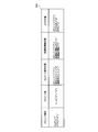
- FIG. 1 is a diagram illustrating an example of a communication system according to an embodiment.
- FIG. 2 is a diagram illustrating an example of the mobile communication system according to the embodiment.
- FIG. 3 is a diagram illustrating an example of dynamic resource sharing according to the embodiment.
- FIG. 4 is a diagram illustrating an example of SFCI according to the embodiment.
- FIG. 5 is a diagram illustrating an example of reducing the information amount of SFCI according to the embodiment.
- FIG. 6 is a diagram illustrating an example of the SFI definition according to the embodiment.
- FIG. 7 is a diagram illustrating an example of slot connection according to the embodiment.
- FIG. 8 is a diagram illustrating an example of the SFCI table according to the embodiment.
- FIG. 1 is a diagram illustrating an example of a communication system according to an embodiment.
- FIG. 2 is a diagram illustrating an example of the mobile communication system according to the embodiment.
- FIG. 3 is a diagram illustrating an example of dynamic resource sharing according to the embodiment.
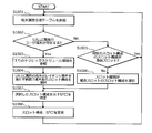
- FIG. 9 is a flowchart of an example of the first process performed by the base station according to the embodiment.
- FIG. 10 is a flowchart illustrating an example of second processing by the base station according to the embodiment.
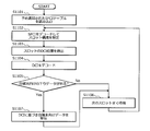
- FIG. 11 is a flowchart illustrating an example of processing by the user terminal according to the embodiment.
- FIG. 12 is a sequence diagram illustrating an example of a registration sequence of the user terminal according to the embodiment.
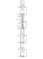
- FIG. 13 is a diagram of an example of the base station according to the embodiment.
- FIG. 14 is a diagram illustrating an example of a user terminal according to the embodiment.
- FIG. 15 is a diagram illustrating an example of overhead reduction by the base station according to the embodiment.
- FIG. 16 is a diagram illustrating an example of a downlink radio frame according to the embodiment.
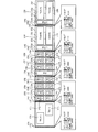
- FIG. 17 is a diagram illustrating another example of the downlink radio frame according to the embodiment.
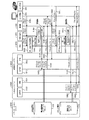
- FIG. 18 is a sequence diagram illustrating an example of the attach process in the mobile communication system according to the embodiment.
- FIG. 19 is a sequence diagram illustrating an example of service provision processing in the mobile communication system according to the embodiment.
- FIG. 20 is a diagram illustrating an example of a hardware configuration of the base station according to the embodiment.
- FIG. 21 is a diagram illustrating an example of a hardware configuration of the user terminal according to the embodiment.
- FIG. 1 is a diagram illustrating an example of a communication system according to an embodiment.
- the communication system 100 includes a first wireless device 110 and a second wireless device 120.
- the first wireless device 110 and the second wireless device 120 are wireless communication devices capable of wireless communication with each other.
- the communication system 100 may include a plurality of second wireless devices 120 capable of wireless communication with the first wireless device 110.
- the first radio apparatus 110 is a base station such as an eNB
- the second radio apparatus 120 is a terminal such as a UE.
- eNB is an abbreviation for evolved Node B.
- UE is an abbreviation for User Equipment (user terminal).
- the first radio apparatus 110 and the second radio apparatus 120 are not limited to this.
- the first wireless device 110 may be a terminal.
- the second radio apparatus 120 may be a base station.
- the first wireless device 110 includes a transmission unit 111 and a processing unit 112.
- the transmission unit 111 wirelessly transmits data to the second wireless device 120 using a transmission frame (wireless frame).
- the transmission frame is a transmission unit of a radio signal transmitted by the first radio apparatus 110, and is a transmission frame having a variable time length.
- An example of the transmission frame is a slot described later.
- the transmission unit 111 can transmit data by switching between a transmission frame having a first time length and a transmission frame having a second time length shorter than the first time length. Further, the transmission unit 111 may be capable of transmitting data using a transmission frame in which the time length of the transmission frame is different from the first time length and the second time length.
- the processing unit 112 stores information (hereinafter referred to as frame information) that can specify the time length of the transmission frame in the transmission frame transmitted by the transmission unit 111.
- the frame information is SFCI, which will be described later, as an example.
- the processing unit 112 stores frame information indicating the first time length in each transmission frame. That is, when the transmission unit 111 transmits data using a transmission frame having a first time length, the processing unit 112 stores frame information for each transmission frame.
- the processing unit 112 when the transmission unit 111 transmits data using a transmission frame having a second time length, the processing unit 112 indicates the second time length only in some transmission frames among a plurality of consecutive transmission frames. Stores frame information. That is, when the transmission unit 111 transmits data using a transmission frame having the second time length, the processing unit 112 stores frame information for each of a plurality of consecutive transmission frames. A part of the plurality of consecutive transmission frames is, for example, the first transmission frame of the plurality of consecutive transmission frames.
- the second radio apparatus 120 includes a receiving unit 121 and a decoding unit 122.
- the receiving unit 121 receives the transmission frame transmitted by the first radio apparatus 110 and outputs the received transmission frame to the decoding unit 122.
- the decoding unit 122 decodes data addressed to the own apparatus from the transmission frame output from the reception unit 121.
- the first radio apparatus 110 illustrated in FIG. 1 stores the frame information indicating the first time length in each of the transmission frames when transmitting data using the transmission frame having the first time length. Can do. Further, when data is transmitted using a transmission frame having a second time length shorter than the first time length, the frame information can be stored in a part of the plurality of continuous transmission frames. Thereby, for example, even when data is transmitted by a transmission frame having a short time length, an increase in overhead due to the frame information can be suppressed as compared with the case where the frame information is stored in each transmission frame. For this reason, it is possible to efficiently perform data transmission using a transmission frame having a variable time length.
- the frame information may be information that directly indicates the time length of the transmission frame, or may be information that indirectly indicates the time length of the transmission frame by a predetermined index or the like.
- the frame information may be information that can specify other information related to the structure of the transmission frame in addition to the time length of the transmission frame.
- the frame information may be information that can specify the time length of the transmission frame and the number of transmission frames whose time length is specified by the frame information (see, eg, FIG. 4). Further, the frame information may be information that can specify each of the connected transmission frames among a plurality of transmission frames whose time length is specified by the frame information. Further, the frame information may be information capable of determining the presence / absence of data for each transmission frame.
- the processing unit 112 of the first wireless device 110 may store position information indicating the position of data (wireless resource) in the transmission frame in the transmission frame.
- the position information is, for example, DCI described later.
- the transmission unit 111 of the first wireless device 110 can connect a plurality of continuous transmission frames and transmit data using the combined transmission frames. There may be.
- the processing unit 112 when the transmission unit 111 transmits data using a transmission frame having a first time length, the processing unit 112 stores position information for each transmission frame. Further, the processing unit 112 may store position information for each of a plurality of transmission frames when the transmission unit 111 transmits data by connecting transmission frames having a second time length. Thereby, for example, even when data is transmitted by a transmission frame having a short time length, an increase in overhead due to the position information can be suppressed as compared with the case where the position information is stored for each transmission frame. For this reason, it is possible to efficiently perform data transmission using a transmission frame having a variable time length. Further, when the transmission unit 111 transmits data without concatenating the transmission frames having the second time length, the processing unit 112 stores position information for each transmission frame, for example.
- FIG. 2 is a diagram illustrating an example of the mobile communication system according to the embodiment.
- the communication system 100 shown in FIG. 1 can be realized by, for example, the mobile communication system 200 shown in FIG.
- the mobile communication system 200 is, for example, a fifth generation mobile communication system.
- the mobile communication system 200 includes user terminals 201 to 203, a base station 210, a PGW 220, and servers 231 and 232.
- PGW is an abbreviation for Packet data network-Gateway.
- the base station 210 is an NR base station corresponding to, for example, a fifth generation mobile communication system.
- the base station 210 is connected to an application server on the Internet such as the servers 231 and 232 via a host device such as the PGW 220.
- the base station 210 forms an NR cell 213 (5G cell), and is multiple-connected to the user terminals 201 to 203 by the NR cell 213.
- the base station 210 is realized by a radio unit 211 that performs transmission / reception of radio signals and the like, and a BBU 212 that controls transmission / reception of radio signals by the radio unit 211.
- BBU is an abbreviation for Base Band Unit (baseband part).
- eMBB is an abbreviation for enhanced Mobile Broad Band, and refers to ultra-high throughput communication that is not severely delayed.
- the eMBB service is, for example, a video distribution service.
- User terminal 203 is an in-vehicle terminal, for example, and receives data of URLLC service from server 232 in NR cell 213.
- URLLC is an abbreviation for Ultra-Reliable and Low Latency Communications (ultra-reliable low-latency communication), and refers to high-reliability, low-latency and mission-critical applications.
- An example of the URLLC service is an in-vehicle V2X service.
- V2X is an abbreviation for Vehicle to Everything.
- the first radio apparatus 110 shown in FIG. 1 can be realized by the base station 210, for example.
- the second radio apparatus 120 shown in FIG. 1 can be realized by at least one of the user terminals 201 to 203, for example.
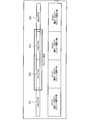
- FIG. 3 is a diagram illustrating an example of dynamic resource sharing according to the embodiment.
- Slots 311 to 317 shown in FIG. 3 are a series of slots set by the base station 210. Of the slots 311 to 317, the slot 311 is the first slot and the slot 317 is the last slot.
- Slots 313 to 316 are slots (minislots) whose time length is shorter than slots 311, 312, and 317 (SLOT).
- the base station 210 monitors a signal from a host device in the downlink direction.
- the host device is a host device such as the PGW 220 illustrated in FIG.
- the signal from the host device is only an eMBB signal at first.
- the base station 210 sets a slot 311 having a relatively long time length, and transmits an eMBB signal in the slot 311.
- the base station 210 sets a slot 312 having a relatively long time after the slot 311, and transmits an eMBB signal in the slot 312.
- the base station 210 receives a highly urgent URLLC signal transmission request from a host device while transmitting an eMBB signal in the slot 312.
- the base station 210 sets slots 313 to 316 having a relatively short time length next to the slot 312 in order to increase the transmission frequency of the URLLC signal.
- the base station 210 transmits an eMBB signal in the slots 313 and 314, and the URLLC signal transmission preparation is completed in the slot 314 period.
- the base station 210 transmits a URLLC signal in the slot 315 next to the slot 314.
- the transmission of the URLLC signal is completed in the slot 316.
- the base station 210 sets a slot 317 having a relatively long time length next to the slot 316 and transmits an eMBB signal in the slot 317.
- the base station 210 dynamically allocates resources to the URLLC in a manner that interrupts the eMBB transmission. Perform resource sharing.
- the base station 210 wirelessly transmits SFCI 321, 322, 324 at the heads of the slots 311, 312, 317 (SLOT), respectively.
- SFCI is an abbreviation for SLOT Format Combination Indicator.
- SFCI is a temporary name and can be changed arbitrarily.
- SFCIs 321, 322, and 324 are information indicating the slot configurations of the slots 311, 312, and 317, respectively.
- the base station 210 wirelessly transmits SFCI 323 at the head of the slot 313 and does not transmit SFCI at the slots 312 and 317 for the slots 313 to 316 (mSLOT).
- SFCI 323 is information indicating the slot configuration of slots 313 to 316.
- the base station 210 arranges SFCI indicating the slot configuration for each slot for slots 311, 312, and 317 (SLOT) having a relatively long time length.
- the base station 210 arranges SFCI indicating the slot configuration of a plurality of slots (slots 313 to 316) only in the first slot (slot 313). .
- Each of the user terminals 201 to 203 specifies the slot configurations of the slots 311, 312, and 317 based on the SFCIs 321, 322, and 324, respectively, and receives data for the own terminal arranged in the slots 311, 312, and 317 Can do. Further, each of the user terminals 201 to 203 can identify the slot configuration of the slots 313 to 316 based on the SFCI 323 and receive data for the own terminal arranged in the slots 313 to 316.
- FIG. 4 is a diagram illustrating an example of SFCI according to the embodiment.
- the SFCI described above includes, for example, the slot type, the number of slots, the slot connection position, the low-delay information position, and the DTX position, as shown in the SFCI 400 shown in FIG.
- the slot type of SFCI 400 indicates the type of the target slot.
- 1 bit is required for the slot type.
- the slot types of SFCIs 321, 322, and 324 arranged at the heads of SLOT slots 311, 312, and 317 are “0”.
- the slot type of SFCI 323 arranged at the head of the slot 313 among the slots 313 to 316 which are mSLOT is “1”.
- the number of slots in SFCI 400 indicates the number of slots whose slot configuration is instructed by SFCI 400.
- 1 to 4 slots are defined as “0” to “3”, respectively.
- 2 bits are required for the number of slots.
- the number of slots of SFCI 321, 322, 324 arranged at the head of each of the slots 311, 312, 317 is “0”.
- the number of slots of SFCI 323 arranged at the head of the slot 313 among the slots 313 to 316 is “3”.
- the slot connection position of SFCI 400 indicates the position of the connected slot among one or more slots whose slot configuration is instructed by SFCI 400.
- the concatenation of slots is, for example, SA (SLOT Aggregation: slot concatenation) that transmits one data across a plurality of slots.
- SA SLOT Aggregation: slot concatenation
- the slot connection position of SFCI 321, 322, 324 arranged at the head of each of the slots 311, 312, 317 where the number of slots is 1 and the slots are not connected is “0000”.
- SA for transmitting one eMBB signal across slots 313 and 314 is performed.
- the header of the eMBB signal and the beginning portion of the payload are arranged in the slot 313, and the payload following the payload portion is arranged in the slot 314.
- the slot connection position of SFCI 323 arranged at the head of slot 313 among slots 313 to 316 is “1100”.
- the low delay information positions of SFCIs 321, 322, and 324 arranged at the heads of the slots 311, 312, and 317 in which the URLLC signal that is low delay information is not stored are “0000”.
- the third slot 315 among the slots 313 to 316 stores the URLLC signal as low delay information
- the low delay information position of the SFCI 323 arranged at the head of the slot 313 among the slots 313 to 316 is stored. Becomes “0010”.
- the DTX positions of SFCIs 321, 322, and 324 arranged at the heads of slots 311, 312, and 317 having no DTX are “0000”.
- the fourth slot 316 among the slots 313 to 316 is DTX
- the DTX position of the SFCI 323 arranged at the head of the slot 313 among the slots 313 to 316 is “0001”.
- FIG. 5 is a diagram illustrating an example of reducing the information amount of SFCI according to the embodiment.
- the horizontal direction indicates the transmission order.
- the slot configuration (slot format) of each slot 501 to 504 Is defined as SFI.
- SFI is an abbreviation for SLOT Format Indication.
- the slot configurations of slots 501 to 504 are SFI # 0 to # 3, respectively.
- FIG. 6 is a diagram illustrating an example of the SFI definition according to the embodiment.
- the SFI described above is defined as an SFI 600 shown in FIG. 6, for example.
- the slot type of SFI 600 indicates the type of the target slot.
- the presence / absence of slot connection in the SFI 600 indicates the presence / absence of connection with the next slot in the target slot.
- the presence / absence of low delay information in the SFI 600 indicates the presence / absence of low delay information (for example, a URLLC signal) in the target slot.
- the presence / absence of DTX in SFI 600 indicates the presence / absence of DTX in the target slot.
- SFI 0 indicates that the slot type of the target slot is SLOT, the target slot is connected to the next slot (SA), and the target slot has no low delay information and DTX. .
- FIG. 7 is a diagram illustrating an example of slot connection according to the embodiment.
- slots 501 and 504 mSLOT # 0, # 3
- slots 502 and 503 mSLOT # 1, # 2 are slot-connected to each other.
- the slot connection of SFI # 0, # 2, and # 3 of slots 501, 503, and 504 is “No”
- the slot connection of SFI # 1 of slot 502 that is connected to slot 503 is “Yes”. It is.
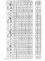
- FIG. 8 is a diagram illustrating an example of the SFCI table according to the embodiment.
- Base station 210 creates SFCI table 800, for example.
- values of SFI # 0 to # 3 applied to slots 501 to 504 are associated with 172 types of SFCI (0 to 171).
- the definition of SFI is associated with each SFCI in addition to the values of SFI # 0 to # 3.
- the slot configuration in which the slot type is SLOT can be considered that all slots 501 to 504 (mSLOT # 0 to # 3) are slot-linked, the presence / absence of slot 501 (mSLOT # 0) being slot-linked is determined. “Yes”.
- the base station 210 creates the SFCI table 800 in which the combinations of the SFIs # 0 to # 3 in the slots 501 to 504 (mSLOT # 0 to # 3) are coded as SFCI.
- the information amount of SFCI can be compressed to 8 bits.
- FIG. 9 is a flowchart of an example of the first process performed by the base station according to the embodiment.
- Base station 210 concerning an embodiment performs each step shown, for example in Drawing 9 as the 1st processing. Moreover, the base station 210 starts each step shown in FIG. 9 when the own station is activated, for example.
- the base station 210 determines radio slot candidates to be operated, and creates an SFCI table corresponding to the determined radio slot candidates (step S901).
- the SFCI table is correspondence information between SFCIs and slot configurations (for example, combinations of SFI # 0 to SFI # 3) as described above.
- the base station 210 creates the SFCI table 800 shown in FIG.
- the SFCI table 800 is stored in the memory of the base station 210, and the base station 210 may read the SFCI table 800 stored in the memory in step S901.
- the signal for starting wireless transmission in step S903 includes, for example, a control signal and a synchronization signal from the base station 210 to each user terminal.
- the base station 210 transmits the SFCI table created in step S901 to each user terminal of the own cell (step S904). For example, the base station 210 starts periodic transmission using broadcast information in the SFCI table.
- the base station 210 determines whether or not an attach request (Attach Request) is received from the user terminal of the own cell (Step S905), and waits until an attach request is received (Step S905: No). Loop).
- the base station 210 transfers the received attach request to the higher-level device (step S906).
- the host device is, for example, an MME (Mobility Management Entity).
- the base station 210 determines whether or not an attach accept (Attach Accept: attach response) to the attach request transferred in step S906 is received from the host device (step S907). Then, the base station 210 waits until an attach accept is received (step S907: No loop).
- step S907 when the attach accept is received (step S907: Yes), the base station 210 proceeds to step S908. That is, the base station 210 checks the attribute of the user terminal that is the transmission source of the attach request received in step S905, stores the attribute in the terminal attribute management table of the local station (step S908), and returns to step S905.
- the attribute of the user terminal is, for example, an attribute of a service of communication performed by the user terminal with the base station 210 (for example, eMBB or URLLC).
- the base station 210 checks the attribute of the user terminal by acquiring terminal attribute information indicating the attribute of the user terminal from the attach request received in step S905 or the attach accept received in step S907. Further, the base station 210 may perform processing for deleting the terminal attribute information of the detached user terminal from the terminal attribute management table of the own station.
- FIG. 10 is a flowchart illustrating an example of second processing by the base station according to the embodiment.
- the base station 210 according to the embodiment executes, for example, each step shown in FIG. 10 as the second process together with the first process shown in FIG. Further, it is assumed that the base station 210 has already started wireless transmission of a signal with the initial value (longest slot) of the slot configuration in step S903 illustrated in FIG. 9 at the start of the second processing.
- the base station 210 refers to its own terminal attribute management table (step S1001).
- the terminal attribute management table is a table in which, for example, the user terminal attributes are stored for each user terminal in step S908 of FIG.
- the base station 210 determines whether there is a user terminal having the URLLC attribute among the user terminals connected to the own cell based on the reference result of the step S1001 (step S1002).
- step S1002 If it is determined in step S1002 that there is a user terminal having the URLLC attribute (step S1002: Yes), the base station 210 refers to downlink traffic schedule information in the own cell (step S1003).
- the base station 210 selects the slot configuration of the maximum slot type within a range that satisfies the latency requirement of the user terminal of the URLLC attribute (step S1004), and proceeds to step S1007.
- the slot configuration selection method by the base station 210 is not limited to this, and various selection methods may be used.
- the base station 210 may always select the slot configuration of the shortest slot type (for example, mSLOT) in step S1004.
- step S1002 determines whether the slot type of the current slot configuration is the longest slot (for example, SLOT) ( Step S1005).
- step S1005 when the slot type of the slot configuration is the longest slot (step S1005: Yes), the base station 210 returns to step S1001 without changing the slot type. If the slot type of the slot configuration is not the longest slot (step S1005: No), the base station 210 selects a slot configuration with the longest slot type (step S1006), and proceeds to step S1007.
- the base station 210 specifies SFCI indicating the slot configuration selected in step S1004 or step S1006 (step S1007).
- the base station 210 specifies SFCI indicating the selected slot configuration based on the SFCI table created in step S901 shown in FIG.
- the base station 210 changes the slot configuration to be used and the SFCI assigned to the head of the slot (step S1008), and returns to step S1001.
- step S1008 for example, the base station 210 changes the slot configuration to be used to the slot configuration selected in step S1004 or step S1006.
- the base station 210 changes the SFCI assigned to the head of the slot to the SFCI set in step S1007.
- the base station 210 arranges SFCI indicating the slot configuration at the head of each slot. Further, when the slot type of the slot configuration to be used is not the longest slot (for example, in the case of mSLOT), the base station 210 sets the plurality of slots at the head of the first slot among the plurality of slots. An SFCI indicating the slot configuration is arranged.
- FIG. 11 is a flowchart illustrating an example of processing by the user terminal according to the embodiment.
- the user terminal 201 according to the embodiment executes, for example, each step shown in FIG. Further, the user terminal 201 executes the steps shown in FIG. 11 after performing attachment (registration processing), for example, toward the base station 210 and the upper network of the base station 210.
- attachment processing attachment processing
- FIG. 11 after performing attachment (registration processing), for example, toward the base station 210 and the upper network of the base station 210.
- the process by the user terminal 201 is demonstrated, the process by the user terminals 202 and 203 is the same as the process by the user terminal 201.
- the user terminal 201 reads the SFCI table notified in advance from the base station 210 (step S1101). For example, the user terminal 201 receives the SFCI table that the base station 210 has started to transmit according to the broadcast information in step S904 shown in FIG. 9, and reads the received SFCI table in step S1101.
- the user terminal 201 decodes (receives) SFCI transmitted from the base station 210 to identify the current slot configuration (step S1102). For example, the user terminal 201 detects the head of each slot based on a synchronization signal included in a signal transmitted from the base station 210, and decodes SFCI from the detected head of each slot. The user terminal 201 identifies the current slot configuration based on the decoded SFCI and the SFCI table read in step S1101.
- DCI position is an abbreviation for Downlink Control Information.
- DCI is information indicating the arrangement of data for user terminals in the slot.
- the user terminal 201 decodes (receives) the DCI from the base station 210 based on the DCI position detected in step S1103 (step S1104).
- the user terminal 201 determines whether there is downlink data for the terminal in the current slot (step S1105).
- step S1105 when there is no downlink data for the terminal itself (step S1105: No), the user terminal 201 waits until the next slot (step S1106), and proceeds to step S1102.
- step S1105 When there is downlink data for the own terminal (step S1105: Yes), the user terminal 201 receives the data for the own terminal based on the DCI (step S1107), and proceeds to step S1106.
- FIG. 12 is a sequence diagram illustrating an example of a registration sequence of the user terminal according to the embodiment.
- EPC network
- EPC is an abbreviation for Evolved Packet Core.
- the EPC 1231 shown in FIG. 12 is a default network, and is used for slice relay, for example.
- the EPC 1232 is a network for eMBB slices.
- the EPC 1233 is a URLLC slice network.
- FIG. 12 as an example, a registration sequence when an eMBB attribute user terminal 201 and a URLLC attribute user terminal 203 make an attach request will be described.
- step S1201 the user terminal 201 having the eMBB attribute transmits an attach request (registration request) for requesting attachment to the base station 210 (step S1201).
- step S1202 the base station 210 transfers the attach request received in step S1201 to the EPC 1231 (step S1202).
- the EPC 1231 determines a transfer destination slice of the attach request from the attribute of the user terminal 201 indicated by the terminal attribute information included in the attach request received in step S1202 (step S1203).
- the EPC 1231 determines the transfer destination slice of the attach request from the user terminal 201 as the EPC 1232 for the eMBB slice.
- the EPC 1231 transfers the attach request received in step S1202 to the EPC 1232 determined in step S1203 (step S1204).
- the EPC 1232 transmits an attach accept (registration acceptance response) for the attach request received in step S1204 to the EPC 1231 (step S1205).
- the EPC 1231 transfers the attach accept received in step S1205 to the base station 210 (step S1206).
- the base station 210 transmits the attach accept received in step S1206 to the user terminal 201 (step S1207).
- the base station 210 stores the attribute of the user terminal 201 in the terminal attribute management table described above (step S1208).
- the base station 210 specifies the attribute of the user terminal 201 based on the terminal attribute information included in the received attach accept, and stores the specified attribute.
- step S1209 the user terminal 203 having the URLLC attribute transmits an attach request for requesting attachment to the base station 210.
- step S1210 the base station 210 transfers the attach request received in step S1209 to the EPC 1231 (step S1210).
- the EPC 1231 determines a transfer destination slice of the attach request from the attribute of the user terminal 203 indicated by the terminal attribute information included in the attach request received in step S1210 (step S1211).
- the EPC 1231 determines the transfer destination slice of the attach request from the user terminal 203 as the EPC 1233 for the URLLC slice.
- the EPC 1231 transfers the attach request received in step S1210 to the EPC 1233 determined in step S1211 (step S1212).
- the EPC 1233 transmits an attach accept for the attach request received in step S1212 to the EPC 1231 (step S1213).
- the EPC 1231 transfers the attach accept received in step S1213 to the base station 210 (step S1214).
- the base station 210 transmits the attach accept received in step S1214 to the user terminal 203 (step S1215). Further, the base station 210 stores the attribute of the user terminal 203 in the terminal attribute management table described above (step S1216). For example, the base station 210 specifies the attribute of the user terminal 203 based on the terminal attribute information included in the received attach accept, and stores the specified attribute.
- FIG. 13 is a diagram of an example of the base station according to the embodiment.
- the base station 210 according to the embodiment includes, for example, an antenna 1301, a reception unit 1310, an upper network interface unit 1320, a transmission unit 1330, and a control unit 1340.
- the antenna 1301 receives a signal wirelessly transmitted from another communication device (for example, the user terminals 201 to 203) and outputs the signal to the receiving unit 1310.
- the antenna 1301 wirelessly transmits the signal output from the transmission unit 1330 to other communication devices (for example, user terminals 201 to 203).
- the reception unit 1310 includes a reception wireless unit 1311, a reception multiple access processing unit 1312, a demodulation / decoding unit 1313, a terminal transmission request detection unit 1314, and an attach request detection unit 1315.
- the reception radio unit 1311 performs an RF reception process on the signal output from the antenna 1301.
- RF is an abbreviation for Radio Frequency.
- the RF reception processing by the reception radio unit 1311 includes, for example, amplification, frequency conversion from the RF band to the baseband, conversion from an analog signal to a digital signal, and the like.
- the reception radio unit 1311 may perform the RF reception process based on the uplink schedule information output from the control unit 1340.
- Reception radio section 1311 outputs the signal subjected to the RF reception process to reception multiple access processing section 1312.
- the reception multiple access processing unit 1312 performs a multiple access process on the reception side for the signal output from the reception radio unit 1311 based on the uplink schedule information output from the control unit 1340. Then, the reception multiple access processing unit 1312 outputs the signal subjected to the reception side multiple access processing to the demodulation / decoding unit 1313.
- the demodulation / decoding unit 1313 demodulates and decodes the signal output from the reception multiple access processing unit 1312 based on the uplink schedule information output from the control unit 1340. Then, the demodulation / decoding unit 1313 outputs a signal obtained by the demodulation and decoding to the terminal transmission request detection unit 1314, the attach request detection unit 1315, and the upper network interface unit 1320.
- the terminal transmission request detection unit 1314 detects a terminal transmission request included in the signal output from the demodulation / decoding unit 1313.
- the terminal transmission request is, for example, a signal from the user terminals 201 to 203 that request transmission permission for uplink signals.
- the terminal transmission request detection unit 1314 outputs the detected terminal transmission request to the control unit 1340.
- the attach request detection unit 1315 detects an attach request included in the signal output from the demodulation / decoding unit 1313.
- the attach request is, for example, a signal from the user terminals 201 to 203 that request attachment (connection).
- the attach request detection unit 1315 outputs the detected attach request to the upper network interface unit 1320.
- the upper network interface unit 1320 transmits the uplink received data included in the signal output from the receiving unit 1310 to the upper network (for example, EPC). Further, the upper network interface unit 1320 transmits control information including the attach request output from the control unit 1340 to the upper network.
- the upper network for example, EPC
- control information including the attach request output from the control unit 1340 to the upper network.
- the upper network interface unit 1320 outputs the control information received from the upper network to the control unit 1340.
- the control information received by the upper network interface unit 1320 from the upper network includes, for example, an attach accept for an attach request.
- the upper network interface unit 1320 outputs downlink transmission data received from the upper network to the transmission unit 1330.
- the transmission unit 1330 includes an attach accept transfer unit 1331, a slot configuration control unit 1332, an SFCI insertion unit 1333, a DCI / UCI insertion unit 1334, an encoding / modulation unit 1335, a transmission multiple access processing unit 1336, a transmission A wireless unit 1337.
- the attach accept transfer unit 1331 outputs the attach accept included in the control information output from the control unit 1340 to the encoding / modulation unit 1335.
- the slot configuration control unit 1332 controls the encoding / modulation unit 1335 so that the slot configuration in the downlink of the base station 210 becomes the slot configuration notified from the control unit 1340.
- the SFCI insertion unit 1333 inserts SFCI into the downlink signal from the base station 210 by outputting the SFCI notified from the control unit 1340 to the encoding / modulation unit 1335.
- the DCI / UCI insertion unit 1334 outputs the DCI and UCI output from the control unit 1340 to the encoding / modulation unit 1335, thereby inserting the DCI and UCI into the downlink signal from the base station 210.
- UCI is an abbreviation for Uplink Control Information.
- the DCI / UCI insertion unit 1334 inserts DCI and UCI by mapping to the position specified by the slot configuration notified from the control unit 1340.
- the signal input to the encoding / modulation unit 1335 includes transmission data from the higher-level network interface unit 1320 and attach accept from the attach accept transfer unit 1331.
- the signal input to the encoding / modulation unit 1335 includes SFCI from the SFCI insertion unit 1333 and DCI and UCI from the DCI / UCI insertion unit 1334.
- the encoding / modulation unit 1335 encodes and modulates the input signal based on the downlink schedule information output from the control unit 1340, and transmits the signal obtained by the encoding and modulation to the transmission multiple access processing unit 1336. Output to.
- the transmission multiple access processing unit 1336 Based on the downlink schedule information output from the control unit 1340, the transmission multiple access processing unit 1336 performs multiple access processing on the transmission side for the signal output from the encoding / modulation unit 1335, and multiple transmission on the transmission side The processed signal is output to transmission radio section 1337.
- the transmission wireless unit 1337 performs RF transmission processing of the signal output from the transmission multiple access processing unit 1336.
- the RF transmission processing by the transmission radio unit 1337 includes, for example, conversion from a digital signal to an analog signal, frequency conversion from a baseband to an RF band, amplification, and the like. Further, the transmission radio unit 1337 may perform the RF transmission process based on the downlink schedule information output from the control unit 1340.
- Transmission multiple access processing section 1336 outputs a signal subjected to RF transmission processing to antenna 1301.
- the control unit 1340 includes an attach request transfer unit 1341, an attach accept reception unit 1342, a terminal attribute management unit 1343, a downlink data detection unit 1344 for the own station, and an SFCI table storage unit 1345. Further, the control unit 1340 includes a slot configuration selection unit 1346, a radio channel control unit 1347, and a downlink radio resource state management unit 1348.
- the attach request transfer unit 1341 outputs the attach request output from the receiving unit 1310 to the upper network interface unit 1320.
- the attach accept receiving unit 1342 receives the attach accept included in the control signal output from the upper network interface unit 1320. Then, the attach accept reception unit 1342 outputs the received attach accept to the transmission unit 1330. Further, the attach accept receiving unit 1342 identifies the attribute of the user terminal corresponding to the attach accept based on the terminal attribute information included in the attach accept, and notifies the terminal attribute managing unit 1343 of the user terminal and the identified attribute. To do.
- the terminal attribute management unit 1343 stores a terminal attribute management table indicating attributes for each user terminal. Also, the terminal attribute management unit 1343 stores the user terminal and attribute combination notified from the attach accept reception unit 1342 in the terminal attribute management table.
- the downlink data detection unit 1344 for the own station detects downlink data (downlink data for the own station) included in the signal output from the upper network interface unit 1320 to the transmission unit 1330. Then, when the downlink data detecting unit 1344 for the own station detects the downlink data for the own station, the downlink data detecting unit 1344 outputs an instruction to transmit the detected downlink data to the radio channel controller 1347.
- the SFCI table storage unit 1345 stores an SFCI table indicating SFCI for each slot configuration.
- the SFCI table storage unit 1345 stores an SFCI table in advance.
- the control unit 1340 may create an SFCI table when the base station 210 is activated, and store the created SFCI table in the SFCI table storage unit 1345.
- the slot configuration selection unit 1346 selects a slot configuration in the base station 210. For example, the slot configuration selection unit 1346 selects the slot configuration having the longest slot type (for example, SLOT) as the initial value of the slot configuration when the base station 210 is activated. In addition, after the base station 210 is activated, the slot configuration selection unit 1346 includes the terminal attribute management table stored in the terminal attribute management unit 1343 and the downlink radio resource state notified from the downlink radio resource state management unit 1348. Based on this, the slot configuration is selected.
- the slot configuration is selected.
- the slot configuration selection unit 1346 notifies the transmission unit 1330 of the selected slot configuration.
- the slot configuration selection unit 1346 specifies SFCI indicating the selected slot configuration from the SFCI table stored in the SFCI table storage unit 1345 and notifies the transmission unit 1330 of the specified SFCI.
- the radio channel controller 1347 is a scheduler that performs scheduling of uplink and downlink radio communications in the base station 210. For example, when a downlink data transmission instruction is output from the downlink data detection unit 1344 for the local station, the radio line control unit 1347 schedules downlink transmission data based on the slot configuration notified from the slot configuration selection unit 1346. . Radio channel control section 1347 then outputs downlink schedule information indicating a scheduling result of downlink transmission data to transmission section 1330. Also, the radio channel controller 1347 outputs DCI indicating the scheduling result of downlink transmission data to the transmitter 1330.
- the radio network control unit 1347 performs scheduling of uplink transmission data and outputs uplink schedule information indicating a scheduling result of the uplink transmission data to the reception unit 1310. Also, the radio channel controller 1347 outputs UCI indicating the scheduling result of uplink transmission data to the transmitter 1330.
- the processing unit 112 of the first radio apparatus 110 illustrated in FIG. 1 is realized by, for example, the slot configuration control unit 1332, the SFCI insertion unit 1333, the DCI / UCI insertion unit 1334, the encoding / modulation unit 1335, and the control unit 1340. Can do.
- FIG. 14 is a diagram illustrating an example of a user terminal according to the embodiment. Although the configuration of the user terminal 201 will be described, the configuration of the user terminals 202 and 203 is the same as that of the user terminal 201. As illustrated in FIG. 14, the user terminal 201 includes, for example, an antenna 1401, a reception unit 1410, an application control unit / user interface unit 1420, a transmission unit 1430, and a control unit 1440.
- the antenna 1401 receives a signal wirelessly transmitted from another communication device (for example, the base station 210) and outputs the signal to the reception unit 1410.
- Antenna 1401 wirelessly transmits the signal output from transmission section 1430 to another communication device (for example, base station 210).
- the reception unit 1410 includes a reception radio unit 1411, a reception multiple access processing unit 1412, a demodulation / decoding unit 1413, an SFCI extraction unit 1414, a DCI / UCI extraction unit 1415, and an attach accept extraction unit 1416.
- the reception radio unit 1411 performs an RF reception process on the signal output from the antenna 1401.
- the RF reception processing by the reception radio unit 1411 includes, for example, amplification, frequency conversion from the RF band to the baseband, conversion from an analog signal to a digital signal, and the like. Further, the reception radio unit 1411 may perform the RF reception process based on the downlink reception control information output from the control unit 1440.
- the reception wireless unit 1411 outputs the signal subjected to the RF reception process to the reception multiple access processing unit 1412.
- the reception multiple access processing unit 1412 performs a multiple access process on the reception side for the signal output from the reception radio unit 1411 based on the downlink reception control information output from the control unit 1440. Then, the reception multiple access processing unit 1412 outputs the signal subjected to the reception side multiple access processing to the demodulation / decoding unit 1413.
- the demodulation / decoding unit 1413 demodulates and decodes the signal output from the reception multiple access processing unit 1412 based on the downlink reception control information output from the control unit 1440.
- Demodulation / decoding section 1413 outputs a signal obtained by demodulation and decoding to SFCI extraction section 1414, DCI / UCI extraction section 1415, attach accept extraction section 1416, and application control section / user interface section 1420.
- the SFCI extraction unit 1414 extracts SFCI included in the signal output from the demodulation / decoding unit 1413. Then, the SFCI extraction unit 1414 outputs the extracted SFCI to the control unit 1440.
- the DCI / UCI extraction unit 1415 extracts DCI and UCI included in the signal output from the demodulation / decoding unit 1413 based on the DCI / UCI reception instruction output from the control unit 1440. Then, the DCI / UCI extraction unit 1415 outputs the extracted DCI and UCI to the control unit 1440.
- the attach accept extraction unit 1416 extracts the attach accept included in the signal output from the demodulation / decoding unit 1413. Then, the attach accept extraction unit 1416 outputs the extracted attach accept to the control unit 1440.
- the application control unit / user interface unit 1420 performs application processing based on downlink received data included in the signal output from the reception unit 1410, and outputs information based on the application processing to the user.
- the application control unit / user interface unit 1420 outputs an attach request based on the application process to the control unit 1440.
- the application control unit / user interface unit 1420 outputs a transmission request signal generation instruction and uplink transmission data to the transmission unit 1430 based on the application process.
- the transmission unit 1430 includes a transmission request signal creation unit 1431, an encoding / modulation unit 1432, a transmission multiple access processing unit 1433, and a transmission radio unit 1434.
- a transmission request signal generation instruction is output from the application control unit / user interface unit 1420
- the transmission request signal generation unit 1431 generates a terminal transmission request for requesting the base station 210 to transmit an uplink signal.
- transmission request signal creation section 1431 outputs the created terminal transmission request to encoding / modulation section 1432.
- the signal input to the encoding / modulation unit 1432 includes an attach request (including terminal attribute information) from the control unit 1440, uplink transmission data from the transmission unit 1430, and a terminal from the transmission request signal generation unit 1431.
- the encoding / modulation unit 1432 encodes and modulates the input signal based on the uplink transmission control information output from the control unit 1440, and outputs the signal obtained by the modulation to the transmission multiple access processing unit 1433 To do.
- the transmission multiple access processing unit 1433 Based on the uplink transmission control information output from the control unit 1440, the transmission multiple access processing unit 1433 performs multiple access processing on the transmission side for the signal output from the encoding / modulation unit 1432, and performs multiple transmission on the transmission side.
- the signal subjected to the connection process is output to transmission radio section 1434.
- the transmission wireless unit 1434 performs RF transmission processing of the signal output from the transmission multiple access processing unit 1433.
- the RF transmission processing by the transmission radio unit 1434 includes, for example, conversion from a digital signal to an analog signal, frequency conversion from a baseband to an RF band, amplification, and the like. Further, the transmission radio unit 1434 may perform an RF transmission process based on the uplink transmission control information output from the control unit 1440. Transmission radio section 1434 outputs the signal subjected to RF transmission processing to antenna 1401.
- the control unit 1440 includes an SFCI table storage unit 1441, an attach control unit 1442, a downlink radio channel control unit 1443, and an uplink radio channel control unit 1444.
- the SFCI table storage unit 1441 stores the SFCI table notified from the base station 210.
- the control unit 1440 causes the SFCI table storage unit 1441 to store the SFCI table received from the base station 210 and received by the receiving unit 1410.
- the attach control unit 1442 performs attach control of the user terminal 201.
- the attach control unit 1442 stores terminal attribute information indicating an attribute (for example, eMBB or URLLC) of the user terminal 201 in the attach request output from the application control unit / user interface unit 1420. Then, the attach control unit 1442 outputs an attach request storing the terminal attribute information to the transmission unit 1430.
- terminal attribute information indicating an attribute (for example, eMBB or URLLC) of the user terminal 201 in the attach request output from the application control unit / user interface unit 1420.
- the attach control unit 1442 outputs an attach request storing the terminal attribute information to the transmission unit 1430.
- the attach control unit 1442 outputs the attach accept to the application control unit / user interface unit 1420.
- the downlink radio channel controller 1443 controls the downlink radio channel in the user terminal 201. For example, the downlink radio channel control unit 1443 identifies the slot configuration indicated by the SFCI output from the reception unit 1410 based on the SFCI table stored in the SFCI table storage unit 1441. Then, downlink radio channel controller 1443 outputs a DCI / UCI reception instruction based on the identified slot configuration to receiver 1410.
- the DCI / UCI reception instruction is information indicating a position (radio resource) where DCI and UCI are stored in a received signal from the base station 210, for example. Further, the downlink radio channel controller 1443 outputs downlink reception control information based on DCI output from the receiver 1410 to the receiver 1410.
- the uplink radio channel control unit 1444 controls the uplink radio channel in the user terminal 201.
- uplink radio channel controller 1444 outputs uplink transmission control information based on UCI output from receiver 1410 to transmitter 1430.
- the receiving unit 121 of the second radio apparatus 120 shown in FIG. 1 can be realized by the antenna 1401 and the receiving radio unit 1411, for example.
- the decoding unit 122 of the second radio apparatus 120 illustrated in FIG. 1 can be realized by the demodulation / decoding unit 1413 and the control unit 1440, for example.
- FIG. 15 is a diagram illustrating an example of overhead reduction by the base station according to the embodiment.
- the slot arrangement 1501 shows a slot arrangement in which SFCI and DCI are arranged at the head of each slot in a slot configuration in which the slot type is mSLOT.
- SFCIs 1521 to 1524 and DCIs 1531 to 1534 are arranged at the heads of slots 1511 to 1514 whose slot type is mSLOT, respectively.
- the slot arrangement 1502 indicates the slot arrangement by the base station 210 according to the embodiment.
- SFCI SFCI 1521
- SFCI 1521 is arranged only at the head of the head slot 1511 for SFCI 1521 to 1524 whose slot type is mSLOT.
- SFCI 1521 is information indicating the slot configurations of slots 1511 to 1514.
- information (SFCI1521) indicating a combination of a plurality of consecutive slots is aggregated and arranged as SFCI, so that control information can be aggregated when slots having a small time length (for example, mSLOT) are consecutive.
- a small time length for example, mSLOT
- FIG. 16 is a diagram illustrating an example of a downlink radio frame according to the embodiment.
- the vertical direction indicates the frequency direction
- the horizontal direction indicates the time direction.
- a configuration example of a downlink radio frame when user terminals 201 and 202 (# 1, # 2) receive an eMBB signal from an eMBB server will be described.
- Slots 1611 to 1613 are a series of slots, and are time-length slots optimized for eMBB. Slots 1611 to 1613 (SLOT # n ⁇ 1 to # n + 1) each have a slot type SLOT, and SFCI 1621 to 1623 and DCI 1631 to 1633 are arranged in slots 1611 to 1613, respectively.
- eMBB transport blocks 1641 to 1643 (TP: Transport Block) for the user terminal 201 (# 1) are multiplexed, respectively.
- eMBB transport blocks 1651 to 1653 (TP) for the user terminal 202 (# 2) are multiplexed in slots 1611 to 1613 (SLOT # n ⁇ 1 to # n + 1), respectively.
- the transport blocks 1641 and 1651 are frequency-multiplexed with each other.
- the transport blocks 1642 and 1652 are frequency-multiplexed with each other.
- the transport blocks 1643 and 1653 are frequency-multiplexed with each other.
- the user terminal 201 specifies the physical resource range (for example, time length and frequency width) of the slot 1611 based on the first SFCI 1621 of the slot 1611 and receives the DCI 1631 based on the specified result. Then, the user terminal 201 receives the transport block 1641 for the own terminal based on the received DCI 1631.
- the physical resource range for example, time length and frequency width
- the user terminal 201 specifies the physical resource range of the slot 1612 based on the first SFCI 1622 of the slot 1612 and receives the DCI 1632 based on the specification result. Then, the user terminal 201 receives the transport block 1642 for the terminal itself based on the received DCI 1632.
- the user terminal 201 specifies the physical resource range of the slot 1613 based on the first SFCI 1623 of the slot 1613, and receives the DCI 1633 based on the specification result. Then, the user terminal 201 receives the transport block 1643 for the own terminal based on the received DCI 1633.
- the user terminal 202 identifies the physical resource range of the slot 1611 based on the first SFCI 1621 of the slot 1611 and receives the DCI 1631 based on the identification result. Then, the user terminal 202 receives the transport block 1651 for the terminal itself based on the received DCI 1631.
- the user terminal 202 identifies the physical resource range of the slot 1612 based on the first SFCI 1622 of the slot 1612 and receives the DCI 1632 based on the identification result. Then, the user terminal 202 receives the transport block 1652 for the own terminal based on the received DCI 1632.
- the user terminal 202 identifies the physical resource range of the slot 1613 based on the first SFCI 1623 of the slot 1613, and receives the DCI 1633 based on the identification result. Then, the user terminal 202 receives the transport block 1653 for the terminal itself based on the received DCI 1633.
- FIG. 17 is a diagram illustrating another example of the downlink radio frame according to the embodiment.
- the vertical direction indicates the frequency direction
- the horizontal direction indicates the time direction.
- FIG. 17 as an example, a configuration example of a downlink radio frame when user terminals 201 and 202 (# 1, # 2) receive an eMBB signal from an eMBB server will be described.
- Slots 1711 to 1727 are a series of slots.
- the slot type of the slot 1711 is SLOT (longest slot), and SFCI 1731 and DCI 1741 are arranged at the head of the slot 1711.
- SFCI 1731 indicates that for slot 1711, the slot type is SLOT, the number of slots is 1, and there is no slot concatenation, low delay information, and DTX (“0000”).
- a transport block 1751 (m) for the user terminal 201 is arranged in the slot 1711.
- the user terminal 201 receives the transport block 1751 based on SFCI 1731 and DCI 1741, as in the example shown in FIG.
- a transport block 1771 (n) for the user terminal 202 is arranged in the slot 1711.
- the user terminal 202 receives the transport block 1771 based on SFCI 1731 and DCI 1741 as in the example shown in FIG.
- the base station 210 switches the slot configuration after the slot 1711 to mSLOT and prepares for transmission of the URLLC signal.
- the slot configuration of the slots 1712 to 1727 is mSLOT.
- Base station 210 arranges SFCI 1732 indicating the slot configuration of slots 1712 to 1715 at the head of slot 1712.
- SFCI 1732 indicates that for slots 1712 to 1715, the slot type is mSLOT, the number of slots is 4, and there is no slot concatenation, low delay information, and DTX (“0000”).
- the base station 210 also arranges transport blocks 1752 to 1755 (m + 1 to m + 4) for the user terminal 201 in slots 1712 to 1715, respectively.
- the base station 210 also arranges transport blocks 1772 to 1775 (n + 1 to n + 4) for the user terminal 202 in slots 1712 to 1715, respectively.
- the base station 210 has DCI 1742 to 1745 arranged in slots 1712 to 1715, respectively.
- DCIs 1742 to 1745 indicate the arrangement of transport blocks 1752 to 1755 for the user terminal 201, respectively.
- DCIs 1742 to 1745 indicate the arrangement of transport blocks 1772 to 1775 for the user terminal 202, respectively.
- the base station 210 also arranges transport blocks 1756 to 1758 (m + 5 to m + 7) for the user terminal 201 in slots 1717 to 1719, respectively.
- the base station 210 also arranges transport blocks 1776 to 1778 (n + 5 to n + 7) for the user terminal 202 in the slots 1717 to 1719, respectively.
- the base station 210 arranges SFCI 1733 indicating the slot configuration of slots 1716 to 1719 at the head of the slot 1716.
- SFCI 1733 indicates that for slots 1716 to 1719, the slot type is mSLOT, the number of slots is 4, and there is no slot concatenation and DTX (“0000”).
- the SFCI 1733 indicates that low delay information (URLLC transport block 1791) is present in the first slot 1716 among the slots 1716 to 1719 ("1000").
- the base station 210 has DCIs 1746 to 1749 located in slots 1716 to 1719, respectively.
- DCI 1746 shows the arrangement of the transport block 1791 for the user terminal 203.
- DCIs 1747 to 1749 indicate the arrangement of transport blocks 1756 to 1758 for the user terminal 201, respectively.
- DCIs 1747 to 1749 indicate the arrangement of transport blocks 1776 to 1778 for the user terminal 202, respectively.
- the URLLC signal for the user terminal 203 is transmitted by semi-persistent scheduling in which the assigned SLOT is fixed in order to improve stability.
- the transport blocks for the user terminals 201 and 202 are transmitted by slot concatenation of three mSLOTs in order to reduce division loss because the signal for the user terminal 203 is fixedly assigned.
- the base station 210 arranges the transport block 1792 in the slot 1720 next to the slot 1719.
- the base station 210 performs slot connection in which one transport block 1759 (m + 8) for the user terminal 201 is arranged over the slots 1721 to 1723.
- the base station 210 performs slot connection in which one transport block 1779 (n + 8) for the user terminal 202 is arranged over the slots 1721 to 1723.
- the base station 210 arranges SFCI 1734 indicating the slot configuration of slots 1720 to 1723 at the head of the slot 1720.
- SFCI 1734 indicates that for slots 1720 to 1723, the slot type is mSLOT, the number of slots is 4, and there is no DTX (“0000”).
- SFCI 1734 indicates that the second to fourth slots 1721 to 1723 out of the slots 1720 to 1723 are slot-connected (“0111”).
- SFCI 1734 indicates that low delay information (URLLC transport block 1792) is present in the first slot 1720 of slots 1720 to 1723 ("1000").
- the base station 210 has a DCI 1750 arranged in the slot 1720.
- the DCI 1750 shows each arrangement of a transport block 1792 for the user terminal 203, a transport block 1759 for the user terminal 201, and a transport block 1779 for the user terminal 202.
- the base station 210 arranges the transport block 1793 in the slot 1724 next to the slot 1723.
- the base station 210 performs slot connection in which one transport block 1760 (m + 9) for the user terminal 201 is arranged over the slots 1725 to 1727.
- the base station 210 performs slot connection in which one transport block 1780 (n + 9) for the user terminal 202 is arranged over the slots 1725 to 1727.
- the base station 210 arranges SFCI 1735 indicating the slot configuration of slots 1724 to 1727 at the head of the slot 1724.
- SFCI 1735 indicates that for slots 1724 to 1727, the slot type is mSLOT, the number of slots is 4, and there is no DTX (“0000”).
- SFCI 1735 indicates that the second to fourth slots 1725 to 1727 among the slots 1724 to 1727 are slot-connected (“0111”).
- SFCI 1735 indicates that low delay information (URLLC transport block 1793) is present in the first slot 1720 of slots 1724 to 1727 ("1000").
- the base station 210 has a DCI 1740 in the slot 1724.
- the DCI 1740 shows each arrangement of a transport block 1793 for the user terminal 203, a transport block 1760 for the user terminal 201, and a transport block 1780 for the user terminal 202.
- FIG. 18 is a sequence diagram illustrating an example of the attach process in the mobile communication system according to the embodiment.
- each step shown in FIG. 18 is executed as the attach process.
- an attach process when the user terminal 201 with the eMBB attribute and the user terminal 203 with the URLLC attribute make an attach request will be described.
- the MME 1801 and the HSS 1802 shown in FIG. MME is an abbreviation for Mobility Management Entity.
- HSS is an abbreviation for Home Subscriber Server (home subscriber server).
- the MME 1801 has an SSF function of selecting and relaying a slice that matches the attribute of the user terminal by inquiring of the HSS 1802.
- SSF is an abbreviation for Slice Selection Function.
- An eMBB slice 1810 shown in FIG. 18 is a network (EPC) in which throughput is important.
- the eMBB slice 1810 includes, for example, an MME 1811 and an S / PGW 1812.
- S / PGW 1812 includes, for example, SGW and PGW.
- SGW is an abbreviation for Serving Gateway.
- a URLLC slice 1820 shown in FIG. 18 is a network (EPC) that places importance on high reliability and low delay.
- URLLC slice 1820 includes MME 1821 and S / PGW 1822, for example.
- S / PGW 1822 includes, for example, SGW and PGW.
- the application server 1830 shown in FIG. 18 includes a high-quality video content server 1831 and an in-vehicle V2x service server 1832.
- the high quality video content server 1831 is a server that provides high quality video content to, for example, the user terminal 201 having the eMBB attribute.
- the in-vehicle V2x service server 1832 is a server that provides the in-vehicle V2x service to the user terminal 203 having the URLLC attribute, for example.
- step S1801 the user terminal 201 transmits an attach request (step S1801).
- the attach request transmitted in step S1801 is transmitted to the HSS 1802 via the base station 210 and the MME 1801, for example.
- the HSS 1802 searches the UE Usage Type indicating the type and requirements of the user terminal 201 based on the received attach request from the user terminal 201 (step S1802).
- the HSS 1802 transmits the UE Usage Type of the user terminal 201 searched in step S1802 to the MME 1801 (step S1803).
- the HSS 1802 may register the UE Usage Type of the user terminal 201 searched in step S1802 in its own database.
- the MME 1801 selects a transfer destination slice of the attach request from the user terminal 201 based on the UE Usage Type received in step S1803 (step S1804). In the example illustrated in FIG. 18, the MME 1801 determines the transfer destination slice of the attach request from the user terminal 201 as the eMBB slice 1810.
- the MME 1801 transmits an attach request from the user terminal 201 to the MME 1811 of the eMBB slice 1810 (step S1805).
- the MME 1811 transmits a create session request (Create Session REQ) requesting a connection between the user terminal 201 and the high-quality video content server 1831 to the S / PGW 1812 (step S1806).
- the MME 1801 transmits a registration notification notifying that the user terminal 201 is registered in the eMBB slice 1810 to the base station 210 (step S1807).
- the S / PGW 1812 establishes a connection between the user terminal 201 and the high quality video content server 1831. Then, the S / PGW 1812 transmits a create session response (Create Session RES) to the create session request received in step S1806 to the MME 1811 (step S1808).
- a create session response Create Session RES
- the MME 1811 transmits an attach accept for the attach request received in step S1805 (step S1809).
- the attach accept transmitted in step S1809 is transmitted to the user terminal 201 via the base station 210, for example.
- step S1810 the user terminal 201 transmits an attach complete (Attach Complete) for the attach accept received in step S1809 (step S1810).
- the attach complete transmitted in step S1810 is transmitted to the MME 1811 via the base station 210, for example.
- step S1811 the user terminal 203 transmits an attach request (step S1811).
- the attach request transmitted in step S1811 is transmitted to the HSS 1802 via the base station 210 and the MME 1801, for example.
- the HSS 1802 searches for a UE Usage Type indicating the type and requirements of the user terminal 203 based on the received attach request from the user terminal 203 (step S1812).
- the HSS 1802 transmits the UE Usage Type of the user terminal 203 searched in step S1812 to the MME 1801 (step S1813).
- the HSS 1802 may register the UE Usage Type of the user terminal 203 searched in step S1812 in its own database.
- the MME 1801 selects a transfer destination slice of the attach request from the user terminal 203 based on the UE Usage Type received in step S1813 (step S1814). In the example illustrated in FIG. 18, the MME 1801 determines the transfer destination slice of the attach request from the user terminal 203 as the URLLC slice 1820.
- the MME 1801 transmits an attach request from the user terminal 203 to the MME 1821 of the URLLC slice 1820 (step S1815).
- the MME 1821 transmits a create session request for requesting a connection between the user terminal 203 and the in-vehicle V2x service server 1832 to the S / PGW 1822 (step S1816).
- the MME 1801 transmits a registration notification for notifying that the user terminal 203 is registered in the URLLC slice 1820 to the base station 210 (step S1817).
- the S / PGW 1822 establishes a connection between the user terminal 203 and the in-vehicle V2x service server 1832. Then, the S / PGW 1822 transmits a create session response to the create session request received in step S1816 to the MME 1821 (step S1818).
- the MME 1821 transmits an attach accept for the attach request received in step S1815 (step S1819).
- the attach accept transmitted in step S1819 is transmitted to the user terminal 203 via the base station 210, for example.
- step S1820 the user terminal 203 transmits an attach complete for the attach accept received in step S1819 (step S1820).
- the attach complete transmitted in step S1820 is transmitted to the MME 1821 via the base station 210, for example.
- FIG. 19 is a sequence diagram illustrating an example of service provision processing in the mobile communication system according to the embodiment.
- each step shown in FIG. 19 is executed as a service providing process after the attach process shown in FIG.
- the user terminal 201 transmits a content request for requesting video content of the high-quality video content server 1831 (step S1901).
- the content request transmitted in step S1901 is transmitted to the high quality video content server 1831 via the base station 210 and the S / PGW 1812, for example.
- the high-quality video content server 1831 transmits the video content corresponding to the content request received in step S1901 (step S1902).
- the video content transmitted in step S1902 is transmitted to the base station 210 via, for example, the S / PGW 1812.
- the base station 210 transmits the video content received in step S1902 to the user terminal 201 (step S1903). At this time, based on the registration notification in step S1807 shown in FIG. 18, the base station 210 transmits the video content with the slot configuration of the slot type SLOT because the signal for the user terminal 201 is the signal of the eMBB slice 1810. To do.
- step S1904 the in-vehicle V2x service server 1832 transmits an emergency control signal to the user terminal 203 (step S1904).
- the emergency control signal transmitted in step S1904 is transmitted to the base station 210 via, for example, the S / PGW 1822.
- the base station 210 transmits the emergency control signal received in step S1904 to the user terminal 203 (step S1905).
- the base station 210 since the signal for the user terminal 203 is the URLLC slice 1820 signal, the base station 210 switches the slot configuration to the mSLOT slot configuration based on the registration notification in step S1817 shown in FIG. Send a signal.
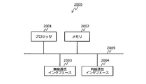
- FIG. 20 is a diagram illustrating an example of a hardware configuration of the base station according to the embodiment.
- the base station 210 shown in FIG. 13 can be realized by the communication device 2000 shown in FIG. 20, for example.
- the communication device 2000 includes a processor 2001, a memory 2002, a wireless communication interface 2003, and a wired communication interface 2004.
- the processor 2001, the memory 2002, the wireless communication interface 2003, and the wired communication interface 2004 are connected by, for example, a bus 2009.
- the processor 2001 is a circuit that performs signal processing, and is, for example, a CPU (Central Processing Unit) that controls the entire communication device 2000.
- the memory 2002 includes, for example, a main memory and an auxiliary memory.
- the main memory is, for example, a RAM (Random Access Memory).
- the main memory is used as a work area for the processor 2001.
- the auxiliary memory is a non-volatile memory such as a magnetic disk or a flash memory.
- Various programs for operating the communication device 2000 are stored in the auxiliary memory. The program stored in the auxiliary memory is loaded into the main memory and executed by the processor 2001.
- processor 2001 and the memory 2002 may be realized by a digital circuit such as an FPGA (Field Programmable Gate Array) or a DSP (Digital Signal Processor).
- FPGA Field Programmable Gate Array
- DSP Digital Signal Processor
- the wireless communication interface 2003 is a communication interface that performs communication with the outside of the communication device 2000 (for example, user terminals 201 to 203) wirelessly.
- the wireless communication interface 2003 is controlled by the processor 2001.
- the wired communication interface 2004 is a communication interface that performs communication with the outside of the communication device 2000 (for example, a host device of the base station 210) by wire.
- the wired communication interface 2004 is controlled by the processor 2001.
- the antenna 1301, the reception unit 1310, and the transmission unit 1330 illustrated in FIG. 13 are included in the wireless communication interface 2003, for example.
- the upper network interface unit 1320 illustrated in FIG. 13 is included in the wired communication interface 2004, for example.
- the control unit 1340 illustrated in FIG. 13 can be realized by the processor 2001 and the memory 2002, for example.
- FIG. 21 is a diagram illustrating an example of a hardware configuration of the user terminal according to the embodiment.
- the hardware configuration of the user terminal 201 will be described, the hardware configuration of the user terminals 202 and 203 is the same as the hardware configuration of the user terminal 201.
- the user terminal 201 illustrated in FIG. 14 can be realized by, for example, the communication device 2100 illustrated in FIG.
- the communication device 2100 includes a processor 2101, a memory 2102, a user interface 2103, and a wireless communication interface 2104.
- the processor 2101, the memory 2102, the user interface 2103, and the wireless communication interface 2104 are connected by, for example, a bus 2109.
- the processor 2101 is a circuit that performs signal processing, and is, for example, a CPU that controls the entire communication device 2100.
- the memory 2102 includes, for example, a main memory and an auxiliary memory.
- the main memory is, for example, a RAM.
- the main memory is used as a work area for the processor 2101.
- the auxiliary memory is a non-volatile memory such as a magnetic disk, an optical disk, or a flash memory.
- Various programs for operating the communication device 2100 are stored in the auxiliary memory.
- the program stored in the auxiliary memory is loaded into the main memory and executed by the processor 2101.
- the processor 2101 and the memory 2102 may be realized by a digital circuit such as an FPGA or a DSP.
- the user interface 2103 includes, for example, an input device that receives an operation input from the user, an output device that outputs information to the user, and the like.
- the input device can be realized by, for example, a key (for example, a keyboard) or a microphone.
- the output device can be realized by, for example, a display or a speaker. Further, an input device and an output device may be realized by a touch panel or the like.
- the user interface 2103 is controlled by the processor 2101.
- the wireless communication interface 2104 is a communication interface that performs communication with the outside of the communication device 2100 (for example, the base station 210) wirelessly.
- the wireless communication interface 2104 is controlled by the processor 2101.
- the antenna 1401, the reception unit 1410, and the application control unit / user interface unit 1420 illustrated in FIG. 14 can be realized by the wireless communication interface 2104, for example.
- the application control unit / user interface unit 1420 illustrated in FIG. 14 can be realized by, for example, the processor 2101, the memory 2102, and the user interface 2103.
- the control unit 1440 illustrated in FIG. 14 can be realized by the processor 2101 and the memory 2102, for example.
- the SFCI when the base station 210 transmits data by SLOT having a long time length, the SFCI can be stored for each slot. Further, when data is transmitted by mSLOT having a shorter time length than SLOT, SFCI can be stored for each of a plurality of slots. Thereby, for example, even when data is transmitted by a short time length mSLOT, an increase in overhead due to SFCI can be suppressed as compared with the case where SFCI is stored for each slot. For this reason, it is possible to efficiently perform data transmission using a slot having a variable time length.
- the base station 210 may transmit data by mSLOT having a short time length, and when a plurality of slots are connected and data is transmitted, the DCI may be stored for each of the plurality of slots.
- the base station 210 may transmit data by mSLOT having a short time length, and when a plurality of slots are connected and data is transmitted, the DCI may be stored for each of the plurality of slots.
- slot types are not limited to these.
- LSLOT Long-SLOT
- nSLOT Normal-SLOT
- mSLOT Mini-SLOT
- LSLOT Long-SLOT
- nSLOT Normal-SLOT
- mSLOT Mini-SLOT
- the wireless device As described above, according to the wireless device, the communication system, and the communication method, it is possible to efficiently perform data transmission using a transmission frame having a variable time length.
- next generation (fifth generation) radio access scheme it is considered to adopt a slot (SLOT) as a physical transmission frame unit in a radio section of transmission information.
- the slot is a transmission frame unit that can be controlled more flexibly and scalable than the subframe in the fourth generation.
- the slot can dynamically change the frame length, which is a signal transmission unit on the time axis, according to the requirements of the information to be transmitted.
- the concept of the above-mentioned slot is regarded as promising because it is efficient to use a transmission unit having an optimal length for the information to be transmitted. .
- eMBB refers to ultra-high throughput communication that is not severely delayed.
- URLLC refers to high-reliability, low-latency and mission-critical applications as described above.
- mMTC is an abbreviation for massive Machine Type Communications, and refers to those that are not severe in terms of the maximum number of users, low throughput, and delay.
- dynamic resource sharing of eMBB and URLLC in the downlink direction is being discussed.
- This is a method of dynamically allocating resources to URLLC by interrupting eMBB transmission when a highly urgent URLLC transmission request is generated for an eMBB to which resources have already been allocated.
- mSLOT mini-SLOT
- the base station gives SFI that specifies the time length of the slot to the head position of each slot.
- SFI is a tentative name. For example, in the use case described above, the base station assigns a slot having a relatively long time length and transmits the information that can accept a normal delay. Further, when transmitting information with a large influence of delay, the base station prepares for transmission of the information by switching to a slot having a relatively short time length.
- the short slot length reduces the radio physical resources that can be used on the time axis due to the division loss, resulting in poor system frequency utilization efficiency.
- a user terminal that receives information whose delay can be tolerated monitors the above-described SFI at a cycle of a short slot interval, and thus wasteful power consumption occurs.
Landscapes
- Engineering & Computer Science (AREA)
- Computer Networks & Wireless Communication (AREA)
- Signal Processing (AREA)
- Mobile Radio Communication Systems (AREA)
Abstract
無線装置(110)は、送信部(111)と、処理部(112)と、を備える。送信部(111)は、第1の時間長の伝送フレームと、第1の時間長より短い第2の時間長の伝送フレームと、を切り替えてデータを送信可能である。処理部(112)は、送信部(111)によって第1の時間長の伝送フレームが送信される場合に伝送フレームのそれぞれに前記第1の時間長を示す情報を格納する。また、処理部(112)は、送信部(111)によって第2の時間長の伝送フレームが送信される場合に連続する複数の伝送フレームのうちの一部の伝送フレームに第2の時間長を示す情報を格納する。
Description
本発明は、無線装置、通信システムおよび通信方法に関する。
従来、3GPPにおいて、第3世代移動通信システム(3G)、第3.9世代移動通信システムに対応するLTE、第4世代移動通信システムに対応するLTE-Advancedなどの移動通信システムの仕様が検討されている。3GPPは3rd Generation Partnership Projectの略である。LTEはLong Term Evolutionの略である。また、第5世代移動通信システム(5G)に関する技術の検討も開始されている。また、第5世代移動通信システムの無線区間では無線データ信号を送信する際の伝送単位として、スロット、ミニスロット(mini-SLOT)構造を採用することが検討されている(たとえば、下記非特許文献1参照。)。
スロットはたとえば連続する7(または14)OFDMシンボルから、ミニスロットはそれよりも少ない数のOFDMシンボルから構成されるようにすることが検討されている。送信するデータのサイズに応じてスロットとミニスロットを使い分けることになるが、更に、ミニスロットは、特に、低遅延伝送が要求されるデータの無線区間での送信のために使用されることも想定されている。スロットとミニスロットは時間多重または周波数多重することが想定され、更に、あるスロットを構成するOFDMシンボルの一部をミニスロットとして使用することも想定されている。スロットとミニスロットの使い分けが容易になるような無線フレーム構成が採用されることになると考えられる。
Nokia、Alcatel-Lucent Shanghai Bell、"On the mini-slot structures in NR"、3GPP R1-1612262、2016年11月
しかしながら、上述した従来技術では、たとえば、伝送するデータに応じてデータの伝送に用いるフレーム構造を可変にする場合は、受信側がフレーム構造を特定するための情報を送信側がフレームごとに送信することになりオーバヘッドが増加する。このため、データ伝送を効率よく行うことができない場合がある。
1つの側面では、本発明は、時間長が可変の伝送フレームによるデータ伝送を効率よく行うことができる無線装置、通信システムおよび通信方法を提供することを目的とする。
上述した課題を解決し、目的を達成するため、1つの実施態様では、第1の時間長の伝送フレームと、前記第1の時間長より短い第2の時間長の伝送フレームと、を切り替えてデータを送信可能な無線装置が、前記第1の時間長の伝送フレームを送信する場合に前記伝送フレームのそれぞれに前記第1の時間長を示す情報を格納し、前記第2の時間長の伝送フレームを送信する場合に連続する複数の前記伝送フレームのうちの一部の伝送フレームに前記第2の時間長を示す情報を格納する無線装置、通信システムおよび通信方法が提案される。
また、別の1つの実施態様では、無線装置が、第1の時間長の伝送フレームと、前記第1の時間長より短い第2の時間長の伝送フレームと、を切り替えてデータを送信可能であり、前記第1の時間長の伝送フレームを送信する場合に前記伝送フレームのそれぞれに前記第1の時間長を示す情報を格納し、前記第2の時間長の伝送フレームを送信する場合に連続する複数の前記伝送フレームのうちの一部の伝送フレームに前記第2の時間長を示す情報を格納する他の無線装置によって送信された伝送フレームを受信し、受信した前記伝送フレームに格納された前記情報に基づいて、受信した前記伝送フレームから自装置宛てのデータを復号する無線装置、通信システムおよび通信方法が提案される。
1つの側面では、本発明は、時間長が可変の伝送フレームによるデータ伝送を効率よく行うことができるという効果を奏する。
以下に図面を参照して、本発明にかかる無線装置、通信システムおよび通信方法の実施の形態を詳細に説明する。
(実施の形態)
(実施の形態にかかる通信システム)
図1は、実施の形態にかかる通信システムの一例を示す図である。図1に示すように、実施の形態にかかる通信システム100は、第1の無線装置110と、第2の無線装置120と、を含む。第1の無線装置110および第2の無線装置120は、互いに無線通信が可能な各無線通信装置である。また、通信システム100には、第1の無線装置110との間で無線通信が可能な第2の無線装置120が複数含まれていてもよい。
(実施の形態にかかる通信システム)
図1は、実施の形態にかかる通信システムの一例を示す図である。図1に示すように、実施の形態にかかる通信システム100は、第1の無線装置110と、第2の無線装置120と、を含む。第1の無線装置110および第2の無線装置120は、互いに無線通信が可能な各無線通信装置である。また、通信システム100には、第1の無線装置110との間で無線通信が可能な第2の無線装置120が複数含まれていてもよい。
一例としては、第1の無線装置110はeNBなどの基地局であり、第2の無線装置120はUEなどの端末である。eNBはevolved Node Bの略である。UEはUser Equipment(ユーザ端末)の略である。ただし、第1の無線装置110および第2の無線装置120はこれに限らない。たとえば、第1の無線装置110は端末であってもよい。また、第2の無線装置120は基地局であってもよい。
第1の無線装置110は、送信部111と、処理部112と、を備える。送信部111は、伝送フレーム(無線フレーム)により第2の無線装置120へデータを無線送信する。伝送フレームは、第1の無線装置110が送信する無線信号の伝送単位であり、時間長が可変な伝送フレームである。伝送フレームは、一例としては後述のスロットである。たとえば、送信部111は、第1の時間長の伝送フレームと、第1の時間長より短い第2の時間長の伝送フレームと、を切り替えて用いてデータを送信可能である。また、送信部111は、さらに伝送フレームの時間長が第1時間長および第2時間長と異なる伝送フレームを用いてデータを送信可能であってもよい。
処理部112は、送信部111によって送信される伝送フレームに、その伝送フレームの時間長を特定可能な情報(以下、フレーム情報と称する。)を格納する。フレーム情報は、一例としては後述のSFCIである。たとえば、処理部112は、送信部111が第1の時間長の伝送フレームによりデータを送信する場合は、伝送フレームのそれぞれに第1の時間長を示すフレーム情報を格納する。すなわち、処理部112は、送信部111が第1の時間長の伝送フレームによりデータを送信する場合は、伝送フレームごとにフレーム情報を格納する。
また、処理部112は、送信部111が第2の時間長の伝送フレームによりデータを送信する場合は、連続する複数の伝送フレームのうちの一部の伝送フレームのみに第2の時間長を示すフレーム情報を格納する。すなわち、処理部112は、送信部111が第2の時間長の伝送フレームによりデータを送信する場合は、連続する複数の伝送フレームごとにフレーム情報を格納する。連続する複数の伝送フレームのうちの一部の伝送フレームは、たとえば連続する複数の伝送フレームのうちの最初の伝送フレームである。
第2の無線装置120は、受信部121と、復号部122と、を備える。受信部121は、第1の無線装置110によって送信された伝送フレームを受信し、受信した伝送フレームを復号部122へ出力する。復号部122は、受信部121から出力された伝送フレームに格納されたフレーム情報に基づいて、受信部121から出力された伝送フレームから自装置宛てのデータを復号する。
このように、図1に示した第1の無線装置110は、第1の時間長の伝送フレームによりデータを送信する場合は第1の時間長を示すフレーム情報を伝送フレームのそれぞれに格納することができる。また、第1の時間長より短い第2の時間長の伝送フレームによりデータを送信する場合はフレーム情報を連続する複数の伝送フレームのうちの一部の伝送フレームに格納することができる。これにより、たとえば短い時間長の伝送フレームによりデータを送信する場合にもフレーム情報を伝送フレームのそれぞれに格納する場合に比べて、フレーム情報によるオーバヘッドの増加を抑制することができる。このため、時間長が可変の伝送フレームによるデータ伝送を効率よく行うことができる。
また、フレーム情報は、伝送フレームの時間長を直接的に示す情報であってもよいし、伝送フレームの時間長を所定のインデックスなどにより間接的に示す情報であってもよい。また、フレーム情報は、伝送フレームの時間長に加えて伝送フレームの構造に関する他の情報を特定可能な情報であってもよい。
たとえば、フレーム情報は、伝送フレームの時間長と、そのフレーム情報により時間長が特定される複数の伝送フレームの数と、を特定可能な情報であってもよい(たとえば図4等参照)。また、フレーム情報は、そのフレーム情報により時間長が特定される複数の伝送フレームのうち連結された各伝送フレームを特定可能な情報であってもよい。また、フレーム情報は、伝送フレームごとにデータの有無を判定可能な情報であってもよい。
また、第1の無線装置110の処理部112は、伝送フレームにおけるデータの位置(無線リソース)を示す位置情報を伝送フレームに格納してもよい。位置情報は、一例としては後述のDCIである。また、第1の無線装置110の送信部111は、第2の時間長の伝送フレームによりデータを送信する場合は、連続する複数の伝送フレームを連結し、連結した伝送フレームによってデータを送信可能であってもよい。
この場合に、処理部112は、たとえば、送信部111が第1の時間長の伝送フレームによりデータを送信する場合は、伝送フレームごとに位置情報を格納する。また、処理部112は、送信部111が第2の時間長の伝送フレームを連結してデータを送信する場合はその複数の伝送フレームごとに位置情報を格納してもよい。これにより、たとえば短い時間長の伝送フレームによりデータを送信する場合にも位置情報を伝送フレームごとに格納する場合に比べて位置情報によるオーバヘッドの増加を抑制することができる。このため、時間長が可変の伝送フレームによるデータ伝送を効率よく行うことができる。また、処理部112は、送信部111が第2の時間長の伝送フレームを連結せずにデータを送信する場合は、たとえば伝送フレームごとに位置情報を格納する。
(実施の形態にかかる移動通信システム)
図2は、実施の形態にかかる移動通信システムの一例を示す図である。図1に示した通信システム100は、たとえば図2に示す移動通信システム200により実現することができる。移動通信システム200は、たとえば第5世代の移動通信システムである。たとえば、移動通信システム200は、ユーザ端末201~203と、基地局210と、PGW220と、サーバ231,232と、を含む。PGWはPacket data network-Gatewayの略である。
図2は、実施の形態にかかる移動通信システムの一例を示す図である。図1に示した通信システム100は、たとえば図2に示す移動通信システム200により実現することができる。移動通信システム200は、たとえば第5世代の移動通信システムである。たとえば、移動通信システム200は、ユーザ端末201~203と、基地局210と、PGW220と、サーバ231,232と、を含む。PGWはPacket data network-Gatewayの略である。
基地局210は、たとえば第5世代の移動通信システムに対応するNRの基地局である。また、基地局210は、PGW220などの上位装置を介して、サーバ231,232などのインターネット上のアプリケーションサーバと接続されている。また、基地局210は、NRセル213(5Gセル)を形成し、NRセル213によってユーザ端末201~203と多元接続されている。たとえば、基地局210は、無線信号の送受信等を行う無線部211と、無線部211による無線信号の送受信を制御するBBU212と、により実現される。BBUはBase Band Unit(ベースバンド部)の略である。
ユーザ端末201,202は、NRセル213において、eMBB系のサービスのデータをサーバ231から受信する。eMBBはenhanced Mobile Broad Bandの略であり、超高スループット通信で遅延にシビアでないものを指す。eMBB系のサービスは、一例としては映像配信サービスである。
ユーザ端末203は、たとえば車載端末であり、NRセル213において、URLLC系のサービスのデータをサーバ232から受信する。URLLCはUltra-Reliable and Low Latency Communications(超高信頼低遅延通信)の略であり、高信頼、低遅延かつミッションクリティカルな用途を指す。URLLC系のサービスは、一例としては車載のV2Xサービスである。V2XはVehicle to Everythingの略である。
図1に示した第1の無線装置110は、たとえば基地局210により実現することができる。図1に示した第2の無線装置120は、たとえばユーザ端末201~203の少なくともいずれかにより実現することができる。
(実施の形態にかかるダイナミック・リソース・シェアリング)
図3は、実施の形態にかかるダイナミック・リソース・シェアリングの一例を示す図である。図3に示すスロット311~317は、基地局210が設定する一連のスロットである。スロット311~317のうち、スロット311が最初のスロットでありスロット317が最後のスロットである。スロット313~316(mSLOT)は、スロット311,312,317(SLOT)より時間長が短いスロット(ミニスロット)である。
図3は、実施の形態にかかるダイナミック・リソース・シェアリングの一例を示す図である。図3に示すスロット311~317は、基地局210が設定する一連のスロットである。スロット311~317のうち、スロット311が最初のスロットでありスロット317が最後のスロットである。スロット313~316(mSLOT)は、スロット311,312,317(SLOT)より時間長が短いスロット(ミニスロット)である。
たとえば、基地局210は、下り方向について、上位装置からの信号を監視する。上位装置は、一例としては図2に示したPGW220などの上位装置である。図3に示す例では、最初は上位装置からの信号がeMBBの信号のみであったとする。この場合に、基地局210は、時間長が比較的長いスロット311を設定し、スロット311においてeMBBの信号を送信する。
また、スロット311においても、上位装置からの信号がeMBBの信号のみであったとする。この場合に、基地局210は、時間長が比較的長いスロット312をスロット311の次に設定し、スロット312においてeMBBの信号を送信する。
また、基地局210は、スロット312においてeMBBの信号を送信中に、上位装置から緊急性の高いURLLCの信号の送信要求を受信したとする。この場合に、基地局210は、URLLCの信号の送信頻度を高めるために、時間長が比較的短いスロット313~316をスロット312の次に設定する。
そして、基地局210は、スロット313,314においてeMBBの信号を送信し、スロット314の期間においてURLLCの信号の送信準備が完了したとする。この場合に、基地局210は、スロット314の次のスロット315においてURLLCの信号を送信する。また、スロット316において、URLLCの信号の送信が完了したとする。この場合に、基地局210は、時間長が比較的長いスロット317をスロット316の次に設定し、スロット317においてeMBBの信号を送信する。
このように、基地局210は、リソース割付をされているeMBBに対して、緊急性の高いURLLCの送信要求が発生した場合に、eMBBの送信に割り込む形でURLLCにダイナミックにリソースを割り当てるダイナミック・リソース・シェアリングを行う。
また、基地局210は、スロット311,312,317(SLOT)の各先頭においてそれぞれSFCI321,322,324を無線送信する。SFCIはSLOT Format Combination Indicatorの略である。またSFCIは仮の名称であり任意に変更することができる。SFCI321,322,324は、それぞれスロット311,312,317のスロット構成を示す情報である。また、基地局210は、スロット313~316(mSLOT)については、スロット313の先頭においてSFCI323を無線送信し、スロット312,317においてはSFCIを送信しない。SFCI323は、スロット313~316のスロット構成を示す情報である。
このように、基地局210は、時間長が比較的長いスロット311,312,317(SLOT)についてはスロット構成を示すSFCIをスロットごとに配置する。また、基地局210は、時間長が比較的短いスロット313~316(mSLOT)については、複数のスロット(スロット313~316)のスロット構成を示すSFCIを先頭のスロット(スロット313)のみに配置する。これにより、時間長が比較的短いスロット313~316(mSLOT)を用いる場合のSFCIによるオーバヘッドの増加を抑制し、時間長が可変のスロットによるデータ伝送を効率よく行うことができる。
ユーザ端末201~203のそれぞれは、SFCI321,322,324に基づいてそれぞれスロット311,312,317のスロット構成を特定し、スロット311,312,317に配置された自端末向けのデータを受信することができる。また、ユーザ端末201~203のそれぞれは、SFCI323に基づいてスロット313~316の各スロット構成を特定し、スロット313~316に配置された自端末向けのデータを受信することができる。
(実施の形態にかかるSFCI)
図4は、実施の形態にかかるSFCIの一例を示す図である。上述したSFCIは、たとえば図4に示すSFCI400に示すように、スロット種別と、スロット数と、スロット連結位置と、低遅延情報位置と、DTX位置と、を項目として含む。
図4は、実施の形態にかかるSFCIの一例を示す図である。上述したSFCIは、たとえば図4に示すSFCI400に示すように、スロット種別と、スロット数と、スロット連結位置と、低遅延情報位置と、DTX位置と、を項目として含む。
SFCI400のスロット種別は、対象のスロットの種別を示す。図4に示す例では、スロット種別としてはSLOTとmSLOTがあり、SLOT=“0”、mSLOT=“1”と定義される。この場合はスロット種別に1ビットを要する。たとえば、図3に示した例では、SLOTであるスロット311,312,317の各先頭に配置されるSFCI321,322,324のスロット種別は“0”になる。また、mSLOTであるスロット313~316のうちスロット313の先頭に配置されるSFCI323のスロット種別は“1”になる。
SFCI400のスロット数は、そのSFCI400によってスロット構成が指示されるスロットの数を示す。図4に示す例では、スロット数の1~4がそれぞれ“0”~“3”と定義される。この場合はスロット数に2ビットを要する。たとえば、図3に示した例では、スロット311,312,317の各先頭に配置されるSFCI321,322,324のスロット数は“0”になる。また、スロット313~316のうちスロット313の先頭に配置されるSFCI323のスロット数は“3”になる。
SFCI400のスロット連結位置は、そのSFCI400によってスロット構成が指示される1以上のスロットのうちの連結されたスロットの位置を示す。スロットの連結は、たとえば1つのデータを複数のスロットにまたがって送信するSA(SLOT Aggregation:スロット連結)である。また、SFCI400のスロット連結位置は、たとえば4ビットバイナリ(スロット数の最大値分のビットマップ)により表される。図4に示す例では、単独スロット=“0”、連結スロット=“1”と定義される。
たとえば、図3に示した例では、スロット数が1でありスロットが連結されないスロット311,312,317の各先頭に配置されるSFCI321,322,324のスロット連結位置は“0000”になる。また、スロット313,314においては、1つのeMBBの信号をスロット313,314にまたがって送信するSAが行われるとする。すなわち、スロット313にはeMBBの信号のヘッダとペイロードの先頭の部分が配置され、スロット314にはそのペイロードの部分の続きのペイロードが配置される。この場合に、スロット313~316のうちスロット313の先頭に配置されるSFCI323のスロット連結位置は“1100”になる。
SFCI400の低遅延情報位置は、そのSFCI400によってスロット構成が指示される1以上のスロットのうちの低遅延が求められる情報(たとえばURLLCの信号)が配置されるスロットの位置を示す。また、SFCI400の低遅延情報位置は、たとえば4ビットバイナリ(スロット数の最大値分のビットマップ)により表される。図4に示す例では、低遅延情報以外=“0”、低遅延情報=“1”と定義される。
たとえば、図3に示した例では、低遅延情報であるURLLCの信号が格納されないスロット311,312,317の各先頭に配置されるSFCI321,322,324の低遅延情報位置は“0000”になる。また、スロット313~316のうち3番目のスロット315には低遅延情報であるURLLCの信号が格納されているため、スロット313~316のうちスロット313の先頭に配置されるSFCI323の低遅延情報位置は“0010”になる。
SFCI400のDTX位置は、そのSFCI400によってスロット構成が指示される1以上のスロットのうちの送信情報が格納されないDTXの位置を示す。また、SFCI400のDTX位置は、たとえば4ビットバイナリ(スロット数の最大値分のビットマップ)により表される。図4に示す例では、DTX以外=“0”、DTX=“1”と定義される。
たとえば、図3に示した例では、DTXがないスロット311,312,317の各先頭に配置されるSFCI321,322,324のDTX位置は“0000”になる。また、スロット313~316のうち4番目のスロット316はDTXであるため、スロット313~316のうちスロット313の先頭に配置されるSFCI323のDTX位置は“0001”になる。
図4に示した例では、SFCI400は1+2+4+4+4=15ビットを要する。ただし、コード化によってSFCIの情報量を減らすことも可能である(たとえば図5~図8参照)。
(実施の形態にかかるSFCIの情報量の低減)
図5は、実施の形態にかかるSFCIの情報量の低減の一例を示す図である。図5において、横方向は送信順を示す。たとえば、図5に示すように、スロット種別がmSLOTである4個のスロット501~504(mSLOT#0~#3)を基準とし、スロット501~504のそれぞれについてそのスロットのスロット構成(スロットフォーマット)をSFIとして定義する。SFIはSLOT Format Indicationの略である。たとえば、スロット501~504のスロット構成をそれぞれSFI#0~#3とする。
図5は、実施の形態にかかるSFCIの情報量の低減の一例を示す図である。図5において、横方向は送信順を示す。たとえば、図5に示すように、スロット種別がmSLOTである4個のスロット501~504(mSLOT#0~#3)を基準とし、スロット501~504のそれぞれについてそのスロットのスロット構成(スロットフォーマット)をSFIとして定義する。SFIはSLOT Format Indicationの略である。たとえば、スロット501~504のスロット構成をそれぞれSFI#0~#3とする。
(実施の形態にかかるSFI定義)
図6は、実施の形態にかかるSFI定義の一例を示す図である。上述したSFIは、たとえば図6に示すSFI600のように定義される。SFI600においては、SFI=0~8のそれぞれについて、スロット種別と、スロット連結有無と、低遅延情報有無と、DTX有無と、の組み合わせが対応付けられている。
図6は、実施の形態にかかるSFI定義の一例を示す図である。上述したSFIは、たとえば図6に示すSFI600のように定義される。SFI600においては、SFI=0~8のそれぞれについて、スロット種別と、スロット連結有無と、低遅延情報有無と、DTX有無と、の組み合わせが対応付けられている。
SFI600のスロット種別は、対象のスロットの種別を示す。図6に示す例では、スロット種別としてはSLOTとmSLOTがある。SFI600のスロット連結有無は、対象のスロットにおける次のスロットとの連結の有無を示す。SFI600の低遅延情報有無は、対象のスロットにおける低遅延情報(たとえばURLLCの信号)の有無を示す。SFI600のDTX有無は、対象のスロットにおけるDTXの有無を示す。
一例としては、SFI=0は、対象のスロットのスロット種別がSLOTであり、対象のスロットが次のスロットと連結(SA)されており、対象のスロットに低遅延情報およびDTXが無いことを示す。
(実施の形態にかかるスロット連結)
図7は、実施の形態にかかるスロット連結の一例を示す図である。たとえば、図7に示すように、スロット501,504(mSLOT#0,#3)はスロット連結しておらず、スロット502,503(mSLOT#1,#2)が互いにスロット連結しているとする。この場合に、スロット501,503,504のSFI#0,#2,#3のスロット連結は“無”であり、スロット503と連結しているスロット502のSFI#1のスロット連結は“有”である。
図7は、実施の形態にかかるスロット連結の一例を示す図である。たとえば、図7に示すように、スロット501,504(mSLOT#0,#3)はスロット連結しておらず、スロット502,503(mSLOT#1,#2)が互いにスロット連結しているとする。この場合に、スロット501,503,504のSFI#0,#2,#3のスロット連結は“無”であり、スロット503と連結しているスロット502のSFI#1のスロット連結は“有”である。
(実施の形態にかかるSFCIテーブル)
図8は、実施の形態にかかるSFCIテーブルの一例を示す図である。基地局210は、たとえばSFCIテーブル800を作成する。SFCIテーブル800においては、172通りのSFCI(0~171)のそれぞれについて、スロット501~504(mSLOT#0~#3)に適用されるSFI#0~#3の値が対応付けられている。なお、図8に示す例では、各SFCIに対してSFI#0~#3の値に加えてSFIの定義も対応付けられている。
図8は、実施の形態にかかるSFCIテーブルの一例を示す図である。基地局210は、たとえばSFCIテーブル800を作成する。SFCIテーブル800においては、172通りのSFCI(0~171)のそれぞれについて、スロット501~504(mSLOT#0~#3)に適用されるSFI#0~#3の値が対応付けられている。なお、図8に示す例では、各SFCIに対してSFI#0~#3の値に加えてSFIの定義も対応付けられている。
SFCI=0~2は、スロット種別がSLOTであるスロット構成を示している。SFCI=0~2においては、スロット501(mSLOT#0)のみにスロット種別がSLOTであるスロット構成が対応付けられ、スロット502~504(mSLOT#1~#3)のスロット構成はd/c(ドントケア)となっている。
たとえば、SFCI=0は、スロット501(mSLOT#0)のSFI#0が0であるスロット構成を示す。すなわち、SFCI=0は、スロット501(mSLOT#0)について、スロット種別がSLOTであり、スロット連結有無が“有”であり、低遅延情報有無およびDTX有無が“無”であるスロット構成を示す。ここで、スロット種別がSLOTであるスロット構成は、スロット501~504(mSLOT#0~#3)を全てスロット連結したものとみなすことができるため、スロット501(mSLOT#0)のスロット連結有無を“有”としている。
SFCI=3~171は、スロット種別がmSLOTであるスロット構成を示している。たとえば、SFCI=3は、スロット501~504(mSLOT#0~#3)のSFI#0~#3のそれぞれが3であるスロット構成を示す。
このように、基地局210は、スロット501~504(mSLOT#0~#3)のSFI#0~#3の各組み合わせをSFCIとしてコード化したSFCIテーブル800を作成する。これにより、たとえばSFCIの情報量を8ビットに圧縮することができる。
(実施の形態にかかる基地局による第1処理)
図9は、実施の形態にかかる基地局による第1処理の一例を示すフローチャートである。実施の形態にかかる基地局210は、第1処理として、たとえば図9に示す各ステップを実行する。また、基地局210は、たとえば自局の起動時に図9に示す各ステップを開始する。
図9は、実施の形態にかかる基地局による第1処理の一例を示すフローチャートである。実施の形態にかかる基地局210は、第1処理として、たとえば図9に示す各ステップを実行する。また、基地局210は、たとえば自局の起動時に図9に示す各ステップを開始する。
まず、基地局210は、運用する無線スロットの候補を決定し、決定した無線スロット候補に対応するSFCIテーブルを作成する(ステップS901)。SFCIテーブルは、上述のようにSFCIとスロット構成(たとえばSFI#0~SFI#3の組み合わせ)との対応情報である。たとえば、基地局210は、図8に示したSFCIテーブル800を作成する。または、基地局210のメモリにはSFCIテーブル800が記憶されており、ステップS901において基地局210はメモリに記憶されたSFCIテーブル800を読み出してもよい。
つぎに、基地局210は、スロット構成の初期値を、スロット種別が最長スロット(たとえばSLOT)のスロット構成に設定する(ステップS902)。たとえば、基地局210は、図8に示したSFCIテーブル800におけるSFCI=0~2が示す各スロット構成のいずれか(一例としてはSFCI=0が示すスロット構成)をスロット構成の初期値として設定する。
つぎに、基地局210は、スロット構成の初期値(最長スロット)に対応するSFCI(たとえばSFCI=0)を各スロットの先頭に付与して信号の無線送信を開始する(ステップS903)。ステップS903によって無線送信が開始される信号には、たとえば基地局210から各ユーザ端末への制御信号や同期信号などが含まれる。
つぎに、基地局210は、ステップS901によって作成したSFCIテーブルを自セルの各ユーザ端末へ送信する(ステップS904)。たとえば、基地局210は、SFCIテーブルの報知情報等による定期的な送信を開始する。
つぎに、基地局210は、自セルのユーザ端末からのアタッチリクエスト(Attach Request:アタッチ要求)を受信したか否かを判断し(ステップS905)、アタッチリクエストを受信するまで待つ(ステップS905:Noのループ)。アタッチリクエストを受信すると(ステップS905:Yes)、基地局210は、受信したアタッチリクエストを上位装置へ転送する(ステップS906)。上位装置は、たとえばMME(Mobility Management Entity:移動性管理エンティティ)である。
つぎに、基地局210は、上位装置から、ステップS906により転送したアタッチリクエストに対するアタッチアクセプト(Attach Accept:アタッチ応答)を受信したか否かを判断する(ステップS907)。そして、基地局210は、アタッチアクセプトを受信するまで待つ(ステップS907:Noのループ)。
ステップS907において、アタッチアクセプトを受信すると(ステップS907:Yes)、基地局210は、ステップS908へ移行する。すなわち、基地局210は、ステップS905において受信したアタッチリクエストの送信元のユーザ端末の属性をチェックして自局の端末属性管理テーブルに記憶し(ステップS908)、ステップS905へ戻る。
ユーザ端末の属性は、たとえばユーザ端末が基地局210との間で行う通信のサービスの属性(たとえばeMBBやURLLC)である。たとえば、基地局210は、ステップS905において受信したアタッチリクエスト、またはステップS907において受信したアタッチアクセプトからユーザ端末の属性を示す端末属性情報を取得することによりユーザ端末の属性をチェックする。また、基地局210は、デタッチしたユーザ端末の端末属性情報を自局の端末属性管理テーブルから削除する処理を行ってもよい。
(実施の形態にかかる基地局による第2処理)
図10は、実施の形態にかかる基地局による第2処理の一例を示すフローチャートである。実施の形態にかかる基地局210は、図9に示した第1処理とともに、第2処理として、たとえば図10に示す各ステップを実行する。また、基地局210は、第2処理の開始時に、図9に示したステップS903によってスロット構成の初期値(最長スロット)による信号の無線送信を開始済みであるとする。
図10は、実施の形態にかかる基地局による第2処理の一例を示すフローチャートである。実施の形態にかかる基地局210は、図9に示した第1処理とともに、第2処理として、たとえば図10に示す各ステップを実行する。また、基地局210は、第2処理の開始時に、図9に示したステップS903によってスロット構成の初期値(最長スロット)による信号の無線送信を開始済みであるとする。
まず、基地局210は、自局の端末属性管理テーブルを参照する(ステップS1001)。端末属性管理テーブルは、たとえば図9のステップS908によってユーザ端末の属性がユーザ端末ごとに記憶されるテーブルである。つぎに、基地局210は、ステップS1001の参照結果に基づいて、自セルに接続した各ユーザ端末の中にURLLC属性のユーザ端末が存在するか否かを判断する(ステップS1002)。
ステップS1002において、URLLC属性のユーザ端末が存在すると判断した場合(ステップS1002:Yes)は、基地局210は、自セルにおける下りのトラヒックスケジュール情報を参照する(ステップS1003)。
つぎに、基地局210は、URLLC属性のユーザ端末のレイテンシ要件を満たす範囲で最大長のスロット種別のスロット構成を選択し(ステップS1004)、ステップS1007へ移行する。ただし、基地局210によるスロット構成の選択方法はこれに限らず、各種の選択方法とすることができる。たとえば、基地局210は、ステップS1004において常に最も短いスロット種別(たとえばmSLOT)のスロット構成を選択してもよい。
ステップS1002において、URLLC属性のユーザ端末が存在しないと判断した場合(ステップS1002:No)は、基地局210は、現状のスロット構成のスロット種別が最長スロット(たとえばSLOT)か否かを判断する(ステップS1005)。
ステップS1005において、スロット構成のスロット種別が最長スロットである場合(ステップS1005:Yes)は、基地局210は、スロット種別を変更せずにステップS1001へ戻る。スロット構成のスロット種別が最長スロットでない場合(ステップS1005:No)は、基地局210は、スロット種別が最長スロットのスロット構成を選択し(ステップS1006)、ステップS1007へ移行する。
つぎに、基地局210は、ステップS1004またはステップS1006によって選択したスロット構成を示すSFCIを特定する(ステップS1007)。たとえば、基地局210は、図9に示したステップS901によって作成したSFCIテーブルに基づいて、選択したスロット構成を示すSFCIを特定する。
つぎに、基地局210は、使用するスロット構成およびスロットの先頭に付与するSFCIを変更し(ステップS1008)、ステップS1001へ戻る。ステップS1008において、基地局210は、たとえば、使用するスロット構成をステップS1004またはステップS1006によって選択したスロット構成に変更する。また、基地局210は、スロットの先頭に付与するSFCIをステップS1007により設定したSFCIに変更する。
また、基地局210は、使用するスロット構成のスロット種別が最長スロットである場合(たとえばSLOTの場合)は、スロット構成を示すSFCIを各スロットの先頭に配置する。また、基地局210は、使用するスロット構成のスロット種別が最長スロットでない場合(たとえばmSLOTの場合)は、複数のスロットごとに、その複数のスロットのうち先頭のスロットの先頭に、その複数のスロットのスロット構成を示すSFCIを配置する。
(実施の形態にかかるユーザ端末による処理)
図11は、実施の形態にかかるユーザ端末による処理の一例を示すフローチャートである。実施の形態にかかるユーザ端末201は、たとえば図11に示す各ステップを実行する。また、ユーザ端末201は、たとえば基地局210および基地局210の上位ネットワークへ向けてアタッチ(登録処理)を実施した後に図11に示す各ステップを実行する。なお、ユーザ端末201による処理について説明するが、ユーザ端末202,203による処理についてもユーザ端末201による処理と同様である。
図11は、実施の形態にかかるユーザ端末による処理の一例を示すフローチャートである。実施の形態にかかるユーザ端末201は、たとえば図11に示す各ステップを実行する。また、ユーザ端末201は、たとえば基地局210および基地局210の上位ネットワークへ向けてアタッチ(登録処理)を実施した後に図11に示す各ステップを実行する。なお、ユーザ端末201による処理について説明するが、ユーザ端末202,203による処理についてもユーザ端末201による処理と同様である。
まず、ユーザ端末201は、基地局210から予め通知されたSFCIテーブルを読み込む(ステップS1101)。たとえば、ユーザ端末201は、図9に示したステップS904によって基地局210が報知情報等により送信を開始したSFCIテーブルを受信し、受信したSFCIテーブルをステップS1101において読み込む。
つぎに、ユーザ端末201は、基地局210から送信されるSFCIをデコード(受信)して現在のスロット構成を特定する(ステップS1102)。たとえば、ユーザ端末201は、基地局210から送信される信号に含まれる同期信号に基づいて各スロットの先頭を検出し、検出した各スロットの先頭からSFCIをデコードする。そして、ユーザ端末201は、デコードしたSFCIと、ステップS1101によって読み込んだSFCIテーブルと、に基づいて現在のスロット構成を特定する。
つぎに、ユーザ端末201は、ステップS1102によって特定したスロット構成に基づいて、現在のスロットのDCIの位置(DCI位置)を検出する(ステップS1103)。DCIはDownlink Control Informationの略である。DCIは、そのスロットにおけるユーザ端末向けのデータの配置を示す情報である。
つぎに、ユーザ端末201は、ステップS1103によって検出したDCI位置に基づいて基地局210からのDCIをデコード(受信)する(ステップS1104)。つぎに、ユーザ端末201は、ステップS1104によりデコードしたDCIに基づいて、現在のスロットに自端末向けの下りデータが有るか否かを判断する(ステップS1105)。
ステップS1105において、自端末向けの下りデータが無い場合(ステップS1105:No)は、ユーザ端末201は、次のスロットまで待機し(ステップS1106)、ステップS1102へ移行する。自端末向けの下りデータが有る場合(ステップS1105:Yes)は、ユーザ端末201は、そのDCIに基づき自端末向けデータを受信し(ステップS1107)、ステップS1106へ移行する。
(実施の形態にかかるユーザ端末の登録シーケンス)
図12は、実施の形態にかかるユーザ端末の登録シーケンスの一例を示すシーケンス図である。5Gにおいて、EPC(ネットワーク)は、ユーザ端末へ提供するサービスの要件に応じて、ネットワークスライスとして分離されることが想定される。EPCはEvolved Packet Coreの略である。
図12は、実施の形態にかかるユーザ端末の登録シーケンスの一例を示すシーケンス図である。5Gにおいて、EPC(ネットワーク)は、ユーザ端末へ提供するサービスの要件に応じて、ネットワークスライスとして分離されることが想定される。EPCはEvolved Packet Coreの略である。
図12に示すEPC1231は、デフォルトのネットワークであり、たとえばスライス中継用に用いられる。EPC1232は、eMBBスライス用のネットワークである。EPC1233は、URLLCスライス用のネットワークである。図12においては、一例として、eMBB属性のユーザ端末201およびURLLC属性のユーザ端末203がアタッチ要求を行う際の登録シーケンスについて説明する。
まず、eMBB属性のユーザ端末201が、アタッチを要求するアタッチリクエスト(登録要求)を基地局210へ送信したとする(ステップS1201)。つぎに、基地局210が、ステップS1201により受信したアタッチリクエストをEPC1231へ転送する(ステップS1202)。
つぎに、EPC1231が、ステップS1202により受信したアタッチリクエストに含まれる端末属性情報が示すユーザ端末201の属性から、そのアタッチリクエストの転送先スライスを決定する(ステップS1203)。図12に示す例では、ユーザ端末201はeMBB属性であるため、EPC1231は、ユーザ端末201からのアタッチリクエストの転送先スライスをeMBBスライス用のEPC1232に決定する。
つぎに、EPC1231が、ステップS1202により受信したアタッチリクエストを、ステップS1203により決定したEPC1232へ転送する(ステップS1204)。つぎに、EPC1232が、ステップS1204により受信したアタッチリクエストに対するアタッチアクセプト(登録受付応答)をEPC1231へ送信する(ステップS1205)。つぎに、EPC1231が、ステップS1205により受信したアタッチアクセプトを基地局210へ転送する(ステップS1206)。
つぎに、基地局210が、ステップS1206により受信したアタッチアクセプトをユーザ端末201へ送信する(ステップS1207)。また、基地局210は、ユーザ端末201の属性を上述の端末属性管理テーブルに記憶する(ステップS1208)。たとえば、基地局210は、受信したアタッチアクセプトに含まれる端末属性情報に基づいてユーザ端末201の属性を特定し、特定した属性を記憶する。
つぎに、URLLC属性のユーザ端末203が、アタッチを要求するアタッチリクエストを基地局210へ送信したとする(ステップS1209)。つぎに、基地局210が、ステップS1209により受信したアタッチリクエストをEPC1231へ転送する(ステップS1210)。
つぎに、EPC1231が、ステップS1210により受信したアタッチリクエストに含まれる端末属性情報が示すユーザ端末203の属性から、そのアタッチリクエストの転送先スライスを決定する(ステップS1211)。図12に示す例では、ユーザ端末203はURLLC属性であるため、EPC1231は、ユーザ端末203からのアタッチリクエストの転送先スライスをURLLCスライス用のEPC1233に決定する。
つぎに、EPC1231が、ステップS1210により受信したアタッチリクエストを、ステップS1211により決定したEPC1233へ転送する(ステップS1212)。つぎに、EPC1233が、ステップS1212により受信したアタッチリクエストに対するアタッチアクセプトをEPC1231へ送信する(ステップS1213)。つぎに、EPC1231が、ステップS1213により受信したアタッチアクセプトを基地局210へ転送する(ステップS1214)。
つぎに、基地局210が、ステップS1214により受信したアタッチアクセプトをユーザ端末203へ送信する(ステップS1215)。また、基地局210は、ユーザ端末203の属性を上述の端末属性管理テーブルに記憶する(ステップS1216)。たとえば、基地局210は、受信したアタッチアクセプトに含まれる端末属性情報に基づいてユーザ端末203の属性を特定し、特定した属性を記憶する。
(実施の形態にかかる基地局)
図13は、実施の形態にかかる基地局の一例を示す図である。図13に示すように、実施の形態にかかる基地局210は、たとえば、アンテナ1301と、受信部1310と、上位ネットワークインタフェース部1320と、送信部1330と、制御部1340と、を備える。
図13は、実施の形態にかかる基地局の一例を示す図である。図13に示すように、実施の形態にかかる基地局210は、たとえば、アンテナ1301と、受信部1310と、上位ネットワークインタフェース部1320と、送信部1330と、制御部1340と、を備える。
アンテナ1301は、他の通信装置(たとえばユーザ端末201~203)から無線送信された信号を受信して受信部1310へ出力する。また、アンテナ1301は、送信部1330から出力された信号を他の通信装置(たとえばユーザ端末201~203)へ無線送信する。
受信部1310は、受信無線部1311と、受信多元接続処理部1312と、復調・復号部1313と、端末送信要求検出部1314と、アタッチリクエスト検出部1315と、を備える。
受信無線部1311は、アンテナ1301から出力された信号のRF受信処理を行う。RFはRadio Frequency(高周波)の略である。受信無線部1311によるRF受信処理には、たとえば、増幅、RF帯からベースバンド帯への周波数変換、アナログ信号からデジタル信号への変換などが含まれる。また、受信無線部1311は、制御部1340から出力された上りスケジュール情報に基づいてRF受信処理を行ってもよい。受信無線部1311は、RF受信処理を行った信号を受信多元接続処理部1312へ出力する。
受信多元接続処理部1312は、制御部1340から出力された上りスケジュール情報に基づいて、受信無線部1311から出力された信号に対して受信側の多元接続処理を行う。そして、受信多元接続処理部1312は、受信側の多元接続処理を行った信号を復調・復号部1313へ出力する。復調・復号部1313は、制御部1340から出力された上りスケジュール情報に基づいて、受信多元接続処理部1312から出力された信号の復調および復号を行う。そして、復調・復号部1313は、復調および復号により得られた信号を端末送信要求検出部1314、アタッチリクエスト検出部1315および上位ネットワークインタフェース部1320へ出力する。
端末送信要求検出部1314は、復調・復号部1313から出力された信号に含まれる端末送信要求を検出する。端末送信要求は、たとえば上り信号の送信許可を要求するユーザ端末201~203からの信号である。端末送信要求検出部1314は、検出した端末送信要求を制御部1340へ出力する。
アタッチリクエスト検出部1315は、復調・復号部1313から出力された信号に含まれるアタッチリクエストを検出する。アタッチリクエストは、たとえばアタッチ(接続)を要求するユーザ端末201~203からの信号である。アタッチリクエスト検出部1315は、検出したアタッチリクエストを上位ネットワークインタフェース部1320へ出力する。
上位ネットワークインタフェース部1320は、受信部1310から出力された信号に含まれる上りの受信データを上位ネットワーク(たとえばEPC)へ送信する。また、上位ネットワークインタフェース部1320は、制御部1340から出力されたアタッチリクエストを含む制御情報を上位ネットワークへ送信する。
また、上位ネットワークインタフェース部1320は、上位ネットワークから受信した制御情報を制御部1340へ出力する。上位ネットワークインタフェース部1320が上位ネットワークから受信する制御情報には、たとえばアタッチリクエストに対するアタッチアクセプトが含まれる。また、上位ネットワークインタフェース部1320は、上位ネットワークから受信した下りの送信データを送信部1330へ出力する。
送信部1330は、アタッチアクセプト転送部1331と、スロット構成制御部1332と、SFCI挿入部1333と、DCI/UCI挿入部1334と、符号化・変調部1335と、送信多元接続処理部1336と、送信無線部1337と、を備える。アタッチアクセプト転送部1331は、制御部1340から出力された制御情報に含まれるアタッチアクセプトを符号化・変調部1335へ出力する。
スロット構成制御部1332は、基地局210の下りリンクにおけるスロット構成が、制御部1340から通知されたスロット構成になるように符号化・変調部1335を制御する。SFCI挿入部1333は、制御部1340から通知されたSFCIを符号化・変調部1335へ出力することにより基地局210からの下り信号にSFCIを挿入する。
DCI/UCI挿入部1334は、制御部1340から出力されたDCIおよびUCIを符号化・変調部1335へ出力することにより、基地局210からの下り信号にDCIおよびUCIを挿入する。UCIはUplink Control Informationの略である。また、DCI/UCI挿入部1334は、制御部1340から通知されたスロット構成で特定される位置にマッピングしてDCIおよびUCIを挿入する。
符号化・変調部1335へ入力される信号には、上位ネットワークインタフェース部1320からの送信データと、アタッチアクセプト転送部1331からのアタッチアクセプトと、が含まれる。また、符号化・変調部1335へ入力される信号には、SFCI挿入部1333からのSFCIと、DCI/UCI挿入部1334からのDCIおよびUCIと、が含まれる。符号化・変調部1335は、制御部1340から出力された下りスケジュール情報に基づいて、入力された信号の符号化および変調を行い、符号化および変調により得られた信号を送信多元接続処理部1336へ出力する。
送信多元接続処理部1336は、制御部1340から出力された下りスケジュール情報に基づいて、符号化・変調部1335から出力された信号に対して送信側の多元接続処理を行い、送信側の多元接続処理を行った信号を送信無線部1337へ出力する。
送信無線部1337は、送信多元接続処理部1336から出力された信号のRF送信処理を行う。送信無線部1337によるRF送信処理には、たとえば、デジタル信号からアナログ信号への変換、ベースバンド帯からRF帯への周波数変換、増幅などが含まれる。また、送信無線部1337は、制御部1340から出力された下りスケジュール情報に基づいてRF送信処理を行ってもよい。送信多元接続処理部1336は、RF送信処理を行った信号をアンテナ1301へ出力する。
制御部1340は、アタッチリクエスト転送部1341と、アタッチアクセプト受信部1342と、端末属性管理部1343と、自局向け下りデータ検出部1344と、SFCIテーブル記憶部1345と、を備える。また、制御部1340は、スロット構成選択部1346と、無線回線制御部1347と、下り無線リソース状態管理部1348と、を備える。アタッチリクエスト転送部1341は、受信部1310から出力されたアタッチリクエストを上位ネットワークインタフェース部1320へ出力する。
アタッチアクセプト受信部1342は、上位ネットワークインタフェース部1320から出力された制御信号に含まれるアタッチアクセプトを受信する。そして、アタッチアクセプト受信部1342は、受信したアタッチアクセプトを送信部1330へ出力する。また、アタッチアクセプト受信部1342は、アタッチアクセプトに含まれる端末属性情報に基づいて、そのアタッチアクセプトに対応するユーザ端末の属性を特定し、そのユーザ端末および特定した属性を端末属性管理部1343へ通知する。
端末属性管理部1343は、ユーザ端末ごとに属性を示す端末属性管理テーブルを記憶する。また、端末属性管理部1343は、アタッチアクセプト受信部1342から通知されたユーザ端末および属性の組み合わせを端末属性管理テーブルに格納する。
自局向け下りデータ検出部1344は、上位ネットワークインタフェース部1320から送信部1330へ出力された信号に含まれる下りデータ(自局向け下りデータ)を検出する。そして、自局向け下りデータ検出部1344は、自局向け下りデータを検出すると、検出した下りデータの送信指示を無線回線制御部1347へ出力する。
SFCIテーブル記憶部1345は、スロット構成ごとのSFCIを示すSFCIテーブルを記憶する。たとえば、SFCIテーブル記憶部1345には予めSFCIテーブルが記憶されている。または、制御部1340は、基地局210の起動時等にSFCIテーブルを作成し、作成したSFCIテーブルをSFCIテーブル記憶部1345に記憶させてもよい。
スロット構成選択部1346は、基地局210におけるスロット構成を選択する。たとえば、スロット構成選択部1346は、基地局210の起動時において、スロット構成の初期値として、スロット種別が最長スロット(たとえばSLOT)のスロット構成を選択する。また、スロット構成選択部1346は、基地局210の起動後において、端末属性管理部1343に記憶された端末属性管理テーブルと、下り無線リソース状態管理部1348から通知される下り無線リソース状態と、に基づいてスロット構成を選択する。
また、スロット構成選択部1346は、選択したスロット構成を送信部1330へ通知する。また、スロット構成選択部1346は、選択したスロット構成を示すSFCIを、SFCIテーブル記憶部1345に記憶されたSFCIテーブルから特定し、特定したSFCIを送信部1330へ通知する。
無線回線制御部1347は、基地局210における上りと下りの無線通信のスケジューリングを行うスケジューラである。たとえば、無線回線制御部1347は、自局向け下りデータ検出部1344から下りデータの送信指示が出力されると、スロット構成選択部1346から通知されたスロット構成に基づいて下り送信データのスケジューリングを行う。そして、無線回線制御部1347は、下り送信データのスケジューリング結果を示す下りスケジュール情報を送信部1330へ出力する。また、無線回線制御部1347は、下り送信データのスケジューリング結果を示すDCIを送信部1330へ出力する。
また、無線回線制御部1347は、受信部1310から端末送信要求が出力されると、上り送信データのスケジューリングを行い、上り送信データのスケジューリング結果を示す上りスケジュール情報を受信部1310へ出力する。また、無線回線制御部1347は、上り送信データのスケジューリング結果を示すUCIを送信部1330へ出力する。
図1に示した第1の無線装置110の送信部111は、たとえばアンテナ1301および送信無線部1337により実現することができる。図1に示した第1の無線装置110の処理部112は、たとえばスロット構成制御部1332、SFCI挿入部1333、DCI/UCI挿入部1334、符号化・変調部1335および制御部1340により実現することができる。
(実施の形態にかかるユーザ端末)
図14は、実施の形態にかかるユーザ端末の一例を示す図である。ユーザ端末201の構成について説明するが、ユーザ端末202,203の構成についてもユーザ端末201の構成と同様である。図14に示すように、ユーザ端末201は、たとえば、アンテナ1401と、受信部1410と、アプリケーション制御部/ユーザインタフェース部1420と、送信部1430と、制御部1440と、を備える。
図14は、実施の形態にかかるユーザ端末の一例を示す図である。ユーザ端末201の構成について説明するが、ユーザ端末202,203の構成についてもユーザ端末201の構成と同様である。図14に示すように、ユーザ端末201は、たとえば、アンテナ1401と、受信部1410と、アプリケーション制御部/ユーザインタフェース部1420と、送信部1430と、制御部1440と、を備える。
アンテナ1401は、他の通信装置(たとえば基地局210)から無線送信された信号を受信して受信部1410へ出力する。また、アンテナ1401は、送信部1430から出力された信号を他の通信装置(たとえば基地局210)へ無線送信する。
受信部1410は、受信無線部1411と、受信多元接続処理部1412と、復調・復号部1413と、SFCI抽出部1414と、DCI/UCI抽出部1415と、アタッチアクセプト抽出部1416と、を備える。
受信無線部1411は、アンテナ1401から出力された信号のRF受信処理を行う。受信無線部1411によるRF受信処理には、たとえば、増幅、RF帯からベースバンド帯への周波数変換、アナログ信号からデジタル信号への変換などが含まれる。また、受信無線部1411は、制御部1440から出力された下り受信制御情報に基づいてRF受信処理を行ってもよい。受信無線部1411は、RF受信処理を行った信号を受信多元接続処理部1412へ出力する。
受信多元接続処理部1412は、制御部1440から出力された下り受信制御情報に基づいて、受信無線部1411から出力された信号に対して受信側の多元接続処理を行う。そして、受信多元接続処理部1412は、受信側の多元接続処理を行った信号を復調・復号部1413へ出力する。
復調・復号部1413は、制御部1440から出力された下り受信制御情報に基づいて、受信多元接続処理部1412から出力された信号の復調および復号を行う。そして、復調・復号部1413は、復調および復号により得られた信号をSFCI抽出部1414、DCI/UCI抽出部1415、アタッチアクセプト抽出部1416およびアプリケーション制御部/ユーザインタフェース部1420へ出力する。
SFCI抽出部1414は、復調・復号部1413から出力された信号に含まれるSFCIを抽出する。そして、SFCI抽出部1414は、抽出したSFCIを制御部1440へ出力する。
DCI/UCI抽出部1415は、制御部1440から出力されたDCI/UCI受信指示に基づいて、復調・復号部1413から出力された信号に含まれるDCIおよびUCIを抽出する。そして、DCI/UCI抽出部1415は、抽出したDCIおよびUCIを制御部1440へ出力する。
アタッチアクセプト抽出部1416は、復調・復号部1413から出力された信号に含まれるアタッチアクセプトを抽出する。そして、アタッチアクセプト抽出部1416は、抽出したアタッチアクセプトを制御部1440へ出力する。
アプリケーション制御部/ユーザインタフェース部1420は、受信部1410から出力された信号に含まれる下りの受信データに基づくアプリケーション処理を行い、アプリケーション処理に基づく情報をユーザへ出力する。
また、アプリケーション制御部/ユーザインタフェース部1420は、アプリケーション処理に基づくアタッチリクエストを制御部1440へ出力する。また、アプリケーション制御部/ユーザインタフェース部1420は、アタッチアクセプトが制御部1440から出力された後に、アプリケーション処理に基づいて、送信要求信号の作成指示および上りの送信データを送信部1430へ出力する。
送信部1430は、送信要求信号作成部1431と、符号化・変調部1432と、送信多元接続処理部1433と、送信無線部1434と、を備える。送信要求信号作成部1431は、アプリケーション制御部/ユーザインタフェース部1420から送信要求信号の作成指示が出力されると、基地局210に対して上り信号の送信許可を要求する端末送信要求を作成する。そして、送信要求信号作成部1431は、作成した端末送信要求を符号化・変調部1432へ出力する。
符号化・変調部1432へ入力される信号には、制御部1440からのアタッチリクエスト(端末属性情報を含む)と、送信部1430からの上りの送信データと、送信要求信号作成部1431からの端末送信要求と、が含まれる。符号化・変調部1432は、制御部1440から出力された上り送信制御情報に基づいて、入力された信号の符号化および変調を行い、変調により得られた信号を送信多元接続処理部1433へ出力する。
送信多元接続処理部1433は、制御部1440から出力された上り送信制御情報に基づいて、符号化・変調部1432から出力された信号に対して送信側の多元接続処理を行い、送信側の多元接続処理を行った信号を送信無線部1434へ出力する。
送信無線部1434は、送信多元接続処理部1433から出力された信号のRF送信処理を行う。送信無線部1434によるRF送信処理には、たとえば、デジタル信号からアナログ信号への変換、ベースバンド帯からRF帯への周波数変換、増幅などが含まれる。また、送信無線部1434は、制御部1440から出力された上り送信制御情報に基づいてRF送信処理を行ってもよい。送信無線部1434は、RF送信処理を行った信号をアンテナ1401へ出力する。
制御部1440は、SFCIテーブル記憶部1441と、アタッチ制御部1442と、下り無線回線制御部1443と、上り無線回線制御部1444と、を備える。SFCIテーブル記憶部1441は、基地局210から通知されたSFCIテーブルを記憶する。たとえば、制御部1440は、受信部1410によって受信された基地局210からのSFCIテーブルをSFCIテーブル記憶部1441に記憶させる。
アタッチ制御部1442は、ユーザ端末201のアタッチ制御を行う。たとえば、アタッチ制御部1442は、アプリケーション制御部/ユーザインタフェース部1420から出力されたアタッチリクエストに、ユーザ端末201の属性(たとえばeMBBまたはURLLC)を示す端末属性情報を格納する。そして、アタッチ制御部1442は、端末属性情報を格納したアタッチリクエストを送信部1430へ出力する。
また、アタッチ制御部1442は、送信部1430へ出力したアタッチリクエストに対するアタッチアクセプトが受信部1410から出力されると、そのアタッチアクセプトをアプリケーション制御部/ユーザインタフェース部1420へ出力する。
下り無線回線制御部1443は、ユーザ端末201における下り無線回線の制御を行う。たとえば、下り無線回線制御部1443は、SFCIテーブル記憶部1441に記憶されたSFCIテーブルに基づいて、受信部1410から出力されたSFCIが示すスロット構成を特定する。そして、下り無線回線制御部1443は、特定したスロット構成に基づくDCI/UCI受信指示を受信部1410へ出力する。DCI/UCI受信指示は、たとえば基地局210からの受信信号においてDCIおよびUCIが格納された位置(無線リソース)を示す情報である。また、下り無線回線制御部1443は、受信部1410から出力されたDCIに基づく下り受信制御情報を受信部1410へ出力する。
上り無線回線制御部1444は、ユーザ端末201における上り無線回線の制御を行う。たとえば、上り無線回線制御部1444は、受信部1410から出力されたUCIに基づく上り送信制御情報を送信部1430へ出力する。
図1に示した第2の無線装置120の受信部121は、たとえばアンテナ1401および受信無線部1411により実現することができる。図1に示した第2の無線装置120の復号部122は、たとえば復調・復号部1413および制御部1440により実現することができる。
(実施の形態にかかる基地局によるオーバヘッドの低減)
図15は、実施の形態にかかる基地局によるオーバヘッドの低減の一例を示す図である。スロット配置1501は、スロット種別がmSLOTであるスロット構成において各スロットの先頭にSFCIおよびDCIを配置するスロット配置を参考として示している。スロット配置1501においては、スロット種別がmSLOTであるスロット1511~1514の先頭にそれぞれSFCI1521~1524およびDCI1531~1534が配置されている。
図15は、実施の形態にかかる基地局によるオーバヘッドの低減の一例を示す図である。スロット配置1501は、スロット種別がmSLOTであるスロット構成において各スロットの先頭にSFCIおよびDCIを配置するスロット配置を参考として示している。スロット配置1501においては、スロット種別がmSLOTであるスロット1511~1514の先頭にそれぞれSFCI1521~1524およびDCI1531~1534が配置されている。
スロット配置1502は、実施の形態にかかる基地局210によるスロット配置を示している。スロット配置1502においては、スロット種別がmSLOTであるSFCI1521~1524について、先頭のスロット1511における先頭にのみSFCI(SFCI1521)が配置されている。そして、SFCI1521は、スロット1511~1514の各スロット構成を示す情報である。
図15に示すように、SFCIとして、複数の連続するスロットの組み合わせを示す情報(SFCI1521)を集約配置することで、時間長の小さいスロット(たとえばmSLOT)が連続した場合に制御情報を集約できる。これにより、分割損による制御情報のオーバヘッドを低減でき、トータルでの周波数リソースの利用効率が向上する。
また、図15のスロット配置1502のように、時間長の小さいスロット(たとえばmSLOT)であっても、同一種別のユーザデータ(たとえばeMBBのみ)がマッピングされている場合は、スロット連結により1つのスロットとして扱うことが可能である。このため、DCIも先頭のスロットのみに配置すればよい。これにより、分割損による制御情報のオーバヘッドを低減でき、トータルでの周波数リソースの利用効率が向上する。
(実施の形態にかかる下り無線フレーム)
図16は、実施の形態にかかる下り無線フレームの一例を示す図である。図16において、縦方向は周波数方向を示し、横方向は時間方向を示す。また、図16においては、一例として、ユーザ端末201,202(#1,#2)がeMBB系サーバからのeMBBの信号を受信している場合の下り無線フレームの構成例について説明する。
図16は、実施の形態にかかる下り無線フレームの一例を示す図である。図16において、縦方向は周波数方向を示し、横方向は時間方向を示す。また、図16においては、一例として、ユーザ端末201,202(#1,#2)がeMBB系サーバからのeMBBの信号を受信している場合の下り無線フレームの構成例について説明する。
スロット1611~1613(SLOT#n-1~#n+1)は、一連の各スロットであり、eMBBに最適化した時間長のスロットである。また、スロット1611~1613(SLOT#n-1~#n+1)はそれぞれスロット種別がSLOTであり、スロット1611~1613にはそれぞれSFCI1621~1623およびDCI1631~1633が配置されている。
スロット1611~1613(SLOT#n-1~#n+1)にはそれぞれユーザ端末201(#1)向けのeMBBのトランスポートブロック1641~1643(TP:Transport Block)が多重されている。また、スロット1611~1613(SLOT#n-1~#n+1)にはそれぞれユーザ端末202(#2)向けのeMBBのトランスポートブロック1651~1653(TP)が多重されている。
また、スロット1611(SLOT#n-1)において、トランスポートブロック1641,1651は互いに周波数多重されている。また、スロット1612(SLOT#n)において、トランスポートブロック1642,1652は互いに周波数多重されている。また、スロット1613(SLOT#n+1)において、トランスポートブロック1643,1653は互いに周波数多重されている。
たとえば、ユーザ端末201は、スロット1611の先頭のSFCI1621に基づいてスロット1611の物理リソース範囲(たとえば時間長および周波数幅)を特定し、特定結果に基づいてDCI1631を受信する。そして、ユーザ端末201は、受信したDCI1631に基づいて自端末向けのトランスポートブロック1641を受信する。
また、ユーザ端末201は、スロット1612の先頭のSFCI1622に基づいてスロット1612の物理リソース範囲を特定し、特定結果に基づいてDCI1632を受信する。そして、ユーザ端末201は、受信したDCI1632に基づいて自端末向けのトランスポートブロック1642を受信する。
また、ユーザ端末201は、スロット1613の先頭のSFCI1623に基づいてスロット1613の物理リソース範囲を特定し、特定結果に基づいてDCI1633を受信する。そして、ユーザ端末201は、受信したDCI1633に基づいて自端末向けのトランスポートブロック1643を受信する。
また、ユーザ端末202は、スロット1611の先頭のSFCI1621に基づいてスロット1611の物理リソース範囲を特定し、特定結果に基づいてDCI1631を受信する。そして、ユーザ端末202は、受信したDCI1631に基づいて自端末向けのトランスポートブロック1651を受信する。
また、ユーザ端末202は、スロット1612の先頭のSFCI1622に基づいてスロット1612の物理リソース範囲を特定し、特定結果に基づいてDCI1632を受信する。そして、ユーザ端末202は、受信したDCI1632に基づいて自端末向けのトランスポートブロック1652を受信する。
また、ユーザ端末202は、スロット1613の先頭のSFCI1623に基づいてスロット1613の物理リソース範囲を特定し、特定結果に基づいてDCI1633を受信する。そして、ユーザ端末202は、受信したDCI1633に基づいて自端末向けのトランスポートブロック1653を受信する。
図17は、実施の形態にかかる下り無線フレームの他の一例を示す図である。図17において、縦方向は周波数方向を示し、横方向は時間方向を示す。また、図17においては、一例として、ユーザ端末201,202(#1,#2)がeMBB系サーバからのeMBBの信号を受信している場合の下り無線フレームの構成例について説明する。
スロット1711~1727は、一連の各スロットである。スロット1711はスロット種別がSLOT(最長スロット)であり、スロット1711の先頭にはSFCI1731およびDCI1741が配置されている。SFCI1731は、スロット1711について、スロット種別がSLOTであり、スロット数が1であり、スロット連結、低遅延情報およびDTXが無い(“0000”)ことを示す。
また、スロット1711にはユーザ端末201向けのトランスポートブロック1751(m)が配置されている。ユーザ端末201は、図16に示した例と同様に、SFCI1731およびDCI1741に基づいてトランスポートブロック1751を受信する。また、スロット1711にはユーザ端末202向けのトランスポートブロック1771(n)が配置されている。ユーザ端末202は、図16に示した例と同様に、SFCI1731およびDCI1741に基づいてトランスポートブロック1771を受信する。
また、図17に示す例では、スロット1711において、基地局210からユーザ端末203へのURLLCの信号の送信要求が発生したとする。この場合に、基地局210は、スロット1711の後のスロット構成をmSLOTに切り替え、URLLCの信号の送信に備える。その結果、図17に示す例では、スロット1712~1727のスロット構成はmSLOTになっている。
基地局210は、スロット1712の先頭に、スロット1712~1715のスロット構成を示すSFCI1732を配置する。SFCI1732は、スロット1712~1715について、スロット種別がmSLOTであり、スロット数が4であり、スロット連結、低遅延情報およびDTXが無い(“0000”)ことを示す。
また、基地局210は、スロット1712~1715に、それぞれユーザ端末201向けのトランスポートブロック1752~1755(m+1~m+4)を配置している。また、基地局210は、スロット1712~1715に、それぞれユーザ端末202向けのトランスポートブロック1772~1775(n+1~n+4)を配置している。
また、基地局210は、スロット1712~1715に、それぞれDCI1742~1745を配置している。DCI1742~1745は、それぞれユーザ端末201向けのトランスポートブロック1752~1755の配置を示す。また、DCI1742~1745は、それぞれユーザ端末202向けのトランスポートブロック1772~1775の配置を示す。
また、図17に示す例では、スロット1712~1715のいずれかにおいて、基地局210からユーザ端末203へのURLLCのトランスポートブロック1791(i)の送信準備が完了したとする。この場合に、基地局210は、スロット1715の次のスロット1716にトランスポートブロック1791を配置する。
また、基地局210は、スロット1717~1719に、それぞれユーザ端末201向けのトランスポートブロック1756~1758(m+5~m+7)を配置している。また、基地局210は、スロット1717~1719に、それぞれユーザ端末202向けのトランスポートブロック1776~1778(n+5~n+7)を配置している。
また、基地局210は、スロット1716の先頭に、スロット1716~1719のスロット構成を示すSFCI1733を配置する。SFCI1733は、スロット1716~1719について、スロット種別がmSLOTであり、スロット数が4であり、スロット連結およびDTXが無い(“0000”)ことを示す。また、SFCI1733は、スロット1716~1719のうちの1番目のスロット1716に低遅延情報(URLLCのトランスポートブロック1791)が有る(“1000”)ことを示す。
また、基地局210は、スロット1716~1719に、それぞれDCI1746~1749を配置している。DCI1746は、ユーザ端末203向けのトランスポートブロック1791の配置を示す。DCI1747~1749は、それぞれユーザ端末201向けのトランスポートブロック1756~1758の配置を示す。また、DCI1747~1749は、それぞれユーザ端末202向けのトランスポートブロック1776~1778の配置を示す。
以降、ユーザ端末203向けのURLLCの信号は、安定性を高めるために、割り当てSLOTを固定するsemi-Persistantスケジューリングにて送信される。ユーザ端末201,202向けのトランスポートブロックは、ユーザ端末203向けの信号が固定割り当てとなったことから、分割損を軽減するために3個のmSLOTを連結したスロット連結によって送信される。
また、図17に示す例では、スロット1716~1719のいずれかにおいて、基地局210からユーザ端末203へのURLLCのトランスポートブロック1792(i+1)の送信準備が完了したとする。この場合に、基地局210は、スロット1719の次のスロット1720にトランスポートブロック1792を配置する。また、基地局210は、スロット1721~1723にわたりユーザ端末201向けの1個のトランスポートブロック1759(m+8)を配置するスロット連結を行う。また、基地局210は、スロット1721~1723にわたりユーザ端末202向けの1個のトランスポートブロック1779(n+8)を配置するスロット連結を行う。
また、基地局210は、スロット1720の先頭に、スロット1720~1723のスロット構成を示すSFCI1734を配置する。SFCI1734は、スロット1720~1723について、スロット種別がmSLOTであり、スロット数が4であり、DTXが無い(“0000”)ことを示す。また、SFCI1734は、スロット1720~1723のうちの2~4番目のスロット1721~1723がスロット連結されている(“0111”)ことを示す。また、SFCI1734は、スロット1720~1723のうちの1番目のスロット1720に低遅延情報(URLLCのトランスポートブロック1792)が有る(“1000”)ことを示す。
また、基地局210は、スロット1720にDCI1750を配置している。DCI1750は、ユーザ端末203向けのトランスポートブロック1792、ユーザ端末201向けのトランスポートブロック1759およびユーザ端末202向けのトランスポートブロック1779の各配置を示す。
また、図17に示す例では、スロット1720~1723のいずれかにおいて、基地局210からユーザ端末203へのURLLCのトランスポートブロック1793(i+2)の送信準備が完了したとする。この場合に、基地局210は、スロット1723の次のスロット1724にトランスポートブロック1793を配置する。また、基地局210は、スロット1725~1727にわたりユーザ端末201向けの1個のトランスポートブロック1760(m+9)を配置するスロット連結を行う。また、基地局210は、スロット1725~1727にわたりユーザ端末202向けの1個のトランスポートブロック1780(n+9)を配置するスロット連結を行う。
また、基地局210は、スロット1724の先頭に、スロット1724~1727のスロット構成を示すSFCI1735を配置する。SFCI1735は、スロット1724~1727について、スロット種別がmSLOTであり、スロット数が4であり、DTXが無い(“0000”)ことを示す。また、SFCI1735は、スロット1724~1727のうちの2~4番目のスロット1725~1727がスロット連結されている(“0111”)ことを示す。また、SFCI1735は、スロット1724~1727のうちの1番目のスロット1720に低遅延情報(URLLCのトランスポートブロック1793)が有る(“1000”)ことを示す。
また、基地局210は、スロット1724にDCI1740を配置している。DCI1740は、ユーザ端末203向けのトランスポートブロック1793、ユーザ端末201向けのトランスポートブロック1760およびユーザ端末202向けのトランスポートブロック1780の各配置を示す。
(実施の形態にかかる移動通信システムにおけるアタッチ処理)
図18は、実施の形態にかかる移動通信システムにおけるアタッチ処理の一例を示すシーケンス図である。実施の形態にかかる移動通信システム200においては、アタッチ処理として、たとえば図18に示す各ステップが実行される。図18に示す例では、一例として、eMBB属性のユーザ端末201およびURLLC属性のユーザ端末203がアタッチ要求を行う際のアタッチ処理について説明する。
図18は、実施の形態にかかる移動通信システムにおけるアタッチ処理の一例を示すシーケンス図である。実施の形態にかかる移動通信システム200においては、アタッチ処理として、たとえば図18に示す各ステップが実行される。図18に示す例では、一例として、eMBB属性のユーザ端末201およびURLLC属性のユーザ端末203がアタッチ要求を行う際のアタッチ処理について説明する。
図18に示すMME1801およびHSS1802は、基地局210の上位装置である。MMEはMobility Management Entity(移動性管理エンティティ)の略である。HSSはHome Subscriber Server(ホーム加入者サーバ)の略である。また、MME1801は、HSS1802に問い合わせることによってユーザ端末の属性に合わせたスライスを選択して中継するSSF機能を有する。SSFはSlice Selection Functionの略である。
図18に示すeMBBスライス1810は、スループットを重視するネットワーク(EPC)である。eMBBスライス1810は、たとえばMME1811およびS/PGW1812を含む。S/PGW1812は、たとえばSGWおよびPGWを含む。SGWはServing Gatewayの略である。図18に示すURLLCスライス1820は、高信頼性および低遅延を重視するネットワーク(EPC)である。URLLCスライス1820は、たとえばMME1821およびS/PGW1822を含む。S/PGW1822は、たとえばSGWおよびPGWを含む。
図18に示すアプリケーションサーバ1830は、高品質映像コンテンツサーバ1831および車載V2xサービスサーバ1832を含む。高品質映像コンテンツサーバ1831は、たとえばeMBB属性のユーザ端末201に対して高品質な映像コンテンツを提供するサーバである。車載V2xサービスサーバ1832は、たとえばURLLC属性のユーザ端末203に対して車載V2xサービスを提供するサーバである。
まず、ユーザ端末201が、アタッチリクエストを送信したとする(ステップS1801)。ステップS1801により送信されたアタッチリクエストは、たとえば基地局210およびMME1801を介してHSS1802へ送信される。
つぎに、HSS1802が、受信したユーザ端末201からのアタッチリクエストに基づいて、ユーザ端末201のタイプや要件を示すUE Usage Typeを検索する(ステップS1802)。つぎに、HSS1802が、ステップS1802によって検索したユーザ端末201のUE Usage TypeをMME1801へ送信する(ステップS1803)。また、HSS1802は、ステップS1802によって検索したユーザ端末201のUE Usage Typeを自装置のデータベースに登録してもよい。
つぎに、MME1801が、ステップS1803により受信したUE Usage Typeに基づいて、ユーザ端末201からのアタッチリクエストの転送先スライスを選択する(ステップS1804)。図18に示す例では、MME1801は、ユーザ端末201からのアタッチリクエストの転送先スライスをeMBBスライス1810に決定する。
つぎに、MME1801が、ユーザ端末201からのアタッチリクエストをeMBBスライス1810のMME1811へ送信する(ステップS1805)。つぎに、MME1811が、ユーザ端末201と高品質映像コンテンツサーバ1831との接続を要求するクリエイトセッションリクエスト(Create Session REQ)をS/PGW1812へ送信する(ステップS1806)。
また、MME1801が、ユーザ端末201がeMBBスライス1810に登録されることを通知する登録通知を基地局210へ送信する(ステップS1807)。
つぎに、S/PGW1812が、ユーザ端末201と高品質映像コンテンツサーバ1831との接続を確立する。そして、S/PGW1812は、ステップS1806において受信したクリエイトセッションリクエストに対するクリエイトセッションレスポンス(Create Session RES)をMME1811へ送信する(ステップS1808)。
つぎに、MME1811が、ステップS1805により受信したアタッチリクエストに対するアタッチアクセプトを送信する(ステップS1809)。ステップS1809によって送信されたアタッチアクセプトは、たとえば基地局210を介してユーザ端末201へ送信される。
つぎに、ユーザ端末201が、ステップS1809によって受信したアタッチアクセプトに対するアタッチコンプリート(Attach Complete)を送信する(ステップS1810)。ステップS1810により送信されたアタッチコンプリートは、たとえば基地局210を介してMME1811へ送信される。
つぎに、ユーザ端末203が、アタッチリクエストを送信したとする(ステップS1811)。ステップS1811により送信されたアタッチリクエストは、たとえば基地局210およびMME1801を介してHSS1802へ送信される。
つぎに、HSS1802が、受信したユーザ端末203からのアタッチリクエストに基づいて、ユーザ端末203のタイプや要件を示すUE Usage Typeを検索する(ステップS1812)。つぎに、HSS1802が、ステップS1812によって検索したユーザ端末203のUE Usage TypeをMME1801へ送信する(ステップS1813)。また、HSS1802は、ステップS1812によって検索したユーザ端末203のUE Usage Typeを自装置のデータベースに登録してもよい。
つぎに、MME1801が、ステップS1813によって受信したUE Usage Typeに基づいて、ユーザ端末203からのアタッチリクエストの転送先スライスを選択する(ステップS1814)。図18に示す例では、MME1801は、ユーザ端末203からのアタッチリクエストの転送先スライスをURLLCスライス1820に決定する。
つぎに、MME1801が、ユーザ端末203からのアタッチリクエストをURLLCスライス1820のMME1821へ送信する(ステップS1815)。つぎに、MME1821が、ユーザ端末203と車載V2xサービスサーバ1832との接続を要求するクリエイトセッションリクエストをS/PGW1822へ送信する(ステップS1816)。
また、MME1801が、ユーザ端末203がURLLCスライス1820に登録されることを通知する登録通知を基地局210へ送信する(ステップS1817)。
つぎに、S/PGW1822が、ユーザ端末203と車載V2xサービスサーバ1832との接続を確立する。そして、S/PGW1822は、ステップS1816において受信したクリエイトセッションリクエストに対するクリエイトセッションレスポンスをMME1821へ送信する(ステップS1818)。
つぎに、MME1821が、ステップS1815により受信したアタッチリクエストに対するアタッチアクセプトを送信する(ステップS1819)。ステップS1819によって送信されたアタッチアクセプトは、たとえば基地局210を介してユーザ端末203へ送信される。
つぎに、ユーザ端末203が、ステップS1819によって受信したアタッチアクセプトに対するアタッチコンプリートを送信する(ステップS1820)。ステップS1820により送信されたアタッチコンプリートは、たとえば基地局210を介してMME1821へ送信される。
(実施の形態にかかる移動通信システムにおけるサービス提供処理)
図19は、実施の形態にかかる移動通信システムにおけるサービス提供処理の一例を示すシーケンス図である。実施の形態にかかる移動通信システム200においては、図18に示したアタッチ処理の後に、サービス提供処理として、たとえば図19に示す各ステップが実行される。
図19は、実施の形態にかかる移動通信システムにおけるサービス提供処理の一例を示すシーケンス図である。実施の形態にかかる移動通信システム200においては、図18に示したアタッチ処理の後に、サービス提供処理として、たとえば図19に示す各ステップが実行される。
まず、ユーザ端末201が、高品質映像コンテンツサーバ1831の映像コンテンツを要求するコンテンツ要求を送信する(ステップS1901)。ステップS1901により送信されたコンテンツ要求は、たとえば基地局210、S/PGW1812を介して高品質映像コンテンツサーバ1831へ送信される。
つぎに、高品質映像コンテンツサーバ1831が、ステップS1901により受信したコンテンツ要求に応じた映像コンテンツを送信する(ステップS1902)。ステップS1902により送信された映像コンテンツは、たとえばS/PGW1812を介して基地局210へ送信される。
つぎに、基地局210は、ステップS1902により受信した映像コンテンツをユーザ端末201へ送信する(ステップS1903)。このとき、基地局210は、図18に示したステップS1807の登録通知に基づいて、ユーザ端末201向けの信号はeMBBスライス1810の信号であるため、スロット種別がSLOTのスロット構成により映像コンテンツを送信する。
つぎに、車載V2xサービスサーバ1832が、ユーザ端末203に対する緊急制御信号を送信したとする(ステップS1904)。ステップS1904により送信された緊急制御信号は、たとえばS/PGW1822を介して基地局210へ送信される。
つぎに、基地局210は、ステップS1904により受信した緊急制御信号をユーザ端末203へ送信する(ステップS1905)。このとき、基地局210は、図18に示したステップS1817の登録通知に基づいて、ユーザ端末203向けの信号はURLLCスライス1820の信号であるため、スロット構成をmSLOTのスロット構成に切り替えて緊急制御信号を送信する。
(実施の形態にかかる基地局のハードウェア構成)
図20は、実施の形態にかかる基地局のハードウェア構成の一例を示す図である。図13に示した基地局210は、たとえば図20に示す通信装置2000によって実現することができる。通信装置2000は、プロセッサ2001と、メモリ2002と、無線通信インタフェース2003と、有線通信インタフェース2004と、を備える。プロセッサ2001、メモリ2002、無線通信インタフェース2003および有線通信インタフェース2004は、たとえばバス2009によって接続される。
図20は、実施の形態にかかる基地局のハードウェア構成の一例を示す図である。図13に示した基地局210は、たとえば図20に示す通信装置2000によって実現することができる。通信装置2000は、プロセッサ2001と、メモリ2002と、無線通信インタフェース2003と、有線通信インタフェース2004と、を備える。プロセッサ2001、メモリ2002、無線通信インタフェース2003および有線通信インタフェース2004は、たとえばバス2009によって接続される。
プロセッサ2001は、信号処理を行う回路であり、たとえば通信装置2000の全体の制御を司るCPU(Central Processing Unit)である。メモリ2002には、たとえばメインメモリおよび補助メモリが含まれる。メインメモリは、たとえばRAM(Random Access Memory)である。メインメモリは、プロセッサ2001のワークエリアとして使用される。補助メモリは、たとえば磁気ディスク、フラッシュメモリなどの不揮発性メモリである。補助メモリには、通信装置2000を動作させる各種のプログラムが記憶されている。補助メモリに記憶されたプログラムは、メインメモリにロードされてプロセッサ2001によって実行される。
また、プロセッサ2001やメモリ2002は、FPGA(Field Programmable Gate Array)やDSP(Digital Signal Processor)などのデジタル回路によって実現されてもよい。
無線通信インタフェース2003は、無線によって通信装置2000の外部(たとえばユーザ端末201~203)との間で通信を行う通信インタフェースである。無線通信インタフェース2003は、プロセッサ2001によって制御される。
有線通信インタフェース2004は、有線によって通信装置2000の外部(たとえば基地局210の上位装置)との間で通信を行う通信インタフェースである。有線通信インタフェース2004は、プロセッサ2001によって制御される。
図13に示したアンテナ1301、受信部1310および送信部1330は、たとえば無線通信インタフェース2003に含まれる。図13に示した上位ネットワークインタフェース部1320は、たとえば有線通信インタフェース2004に含まれる。図13に示した制御部1340は、たとえばプロセッサ2001およびメモリ2002により実現することができる。
(実施の形態にかかるユーザ端末のハードウェア構成)
図21は、実施の形態にかかるユーザ端末のハードウェア構成の一例を示す図である。ユーザ端末201のハードウェア構成について説明するが、ユーザ端末202,203のハードウェア構成についてもユーザ端末201のハードウェア構成と同様である。図14に示したユーザ端末201は、たとえば図21に示す通信装置2100によって実現することができる。
図21は、実施の形態にかかるユーザ端末のハードウェア構成の一例を示す図である。ユーザ端末201のハードウェア構成について説明するが、ユーザ端末202,203のハードウェア構成についてもユーザ端末201のハードウェア構成と同様である。図14に示したユーザ端末201は、たとえば図21に示す通信装置2100によって実現することができる。
通信装置2100は、プロセッサ2101と、メモリ2102と、ユーザインタフェース2103と、無線通信インタフェース2104と、を備える。プロセッサ2101、メモリ2102、ユーザインタフェース2103および無線通信インタフェース2104は、たとえばバス2109によって接続される。
プロセッサ2101は、信号処理を行う回路であり、たとえば通信装置2100の全体の制御を司るCPUである。メモリ2102には、たとえばメインメモリおよび補助メモリが含まれる。メインメモリは、たとえばRAMである。メインメモリは、プロセッサ2101のワークエリアとして使用される。補助メモリは、たとえば磁気ディスク、光ディスク、フラッシュメモリなどの不揮発性メモリである。補助メモリには、通信装置2100を動作させる各種のプログラムが記憶されている。補助メモリに記憶されたプログラムは、メインメモリにロードされてプロセッサ2101によって実行される。また、プロセッサ2101やメモリ2102は、FPGAやDSPなどのデジタル回路によって実現されてもよい。
ユーザインタフェース2103は、たとえば、ユーザからの操作入力を受け付ける入力デバイスや、ユーザへ情報を出力する出力デバイスなどを含む。入力デバイスは、たとえばキー(たとえばキーボード)やマイクなどによって実現することができる。出力デバイスは、たとえばディスプレイやスピーカなどによって実現することができる。また、タッチパネルなどによって入力デバイスおよび出力デバイスを実現してもよい。ユーザインタフェース2103は、プロセッサ2101によって制御される。
無線通信インタフェース2104は、無線によって通信装置2100の外部(たとえば基地局210)との間で通信を行う通信インタフェースである。無線通信インタフェース2104は、プロセッサ2101によって制御される。
図14に示したアンテナ1401、受信部1410およびアプリケーション制御部/ユーザインタフェース部1420は、たとえば無線通信インタフェース2104により実現することができる。図14に示したアプリケーション制御部/ユーザインタフェース部1420は、たとえばプロセッサ2101、メモリ2102およびユーザインタフェース2103により実現することができる。図14に示した制御部1440は、たとえばプロセッサ2101およびメモリ2102により実現することができる。
このように、実施の形態によれば、基地局210が、時間長が長いSLOTによりデータを送信する場合はSFCIをスロットごとに格納することができる。また、SLOTより時間長が短いmSLOTによりデータを送信する場合はSFCIを複数のスロットごとに格納することができる。これにより、たとえば短い時間長のmSLOTによりデータを送信する場合にもSFCIをスロットごとに格納する場合に比べて、SFCIによるオーバヘッドの増加を抑制することができる。このため、時間長が可変のスロットによるデータ伝送を効率よく行うことができる。
また、基地局210は、時間長が短いmSLOTによりデータを送信し、複数のスロットが連結されてデータが送信される場合はその複数のスロットごとにDCIを格納してもよい。これにより、たとえば短い時間長のスロットによりデータを送信する場合にもDCIをスロットごとに格納する場合に比べてDCIによるオーバヘッドの増加を抑制することができる。このため、時間長が可変のスロットによるデータ伝送を効率よく行うことができる。
上述した実施の形態では、スロット種別としてSLOTおよびmSLOTの2種類を用いる構成について説明したが、スロット種別はこれらに限らない。たとえば、スロット種別として、時間長が長いスロット(LSLOT:Long-SLOT)、時間長が中間であるスロット(nSLOT:Normal-SLOT)、時間長が短いスロット(mSLOT:Mini-SLOT)の3つを用いる構成としてもよい。また、4つ以上のスロット種別を用いる構成としてもよい。
以上説明したように、無線装置、通信システムおよび通信方法によれば、時間長が可変の伝送フレームによるデータ伝送を効率よく行うことができる。
次世代(第5世代)の無線アクセス方式においては、伝送情報の無線区間における物理的な伝送フレーム単位としてスロット(SLOT)を採用することが検討されている。スロットは、第4世代におけるサブフレーム(Subframe)より柔軟かつスケーラブルに制御可能な伝送フレーム単位である。たとえば、スロットは、時間軸上における信号の伝送単位であるフレーム長を、送信する情報の要求条件に応じて動的に変更することが可能である。
一般に、単位時間当たりのデータ量が多いほど、つまり高速データ伝送になるほど、オーバヘッドを少なくすることを要し、長いフレーム長を用いる方が高効率になる。一方で、単位時間当たりのデータ量は少ないが、伝送遅延が許容できない即時性を要求されるような制御データは、短いフレーム長の時間間隔で単位時間当たりの伝送機会を増やす方が望ましい。このように、伝送する情報に要求される条件が異なる場合は、伝送する情報に最適な長さの伝送単位を用いるのが効率的であるという理由から上述のスロットという概念が有力視されている。
また、第5世代無線アクセス方式においては、送信するユーザアプリケーションおよびユーザ情報を大きくeMBB、URLLC、mMTCの3種類に分類し、それぞれに対する要求条件をまとめている。eMBBは、上述のように超高スループット通信で遅延にシビアでないものを指す。URLLCは、上述のように高信頼、低遅延かつミッションクリティカルな用途を指す。mMTCはmassive Machine Type Communicationsの略であり、極大ユーザ数、低スループット、遅延にはシビアでないものを指す。
たとえば、ひとつのユースケースとして、下り方向におけるeMBBとURLLCのダイナミック・リソース・シェアリングが議論されている。これは、すでにリソース割付をされているeMBBに対して、緊急性の高いURLLCの送信要求が発生した場合に、eMBBの送信に割り込む形でURLLCにダイナミックにリソースを割り当てる方法である。eMBBとURLLCのダイナミック・リソース・シェアリングにおいて、URLLCを送信する場合にmSLOT(mini-SLOT:ミニスロット)を使用することが検討されている。
ダウンリンクにおいて可変長のスロットを時間軸上で多重して送信する場合は、ユーザ端末がスロットの構成を特定するための情報を要する。このため、基地局が各スロットの先頭位置にスロットの時間長を特定するSFIを付与することが検討されている。なおSFIは仮称である。たとえば、上述のユースケースにおいては、基地局は、通常の遅延が許容できる情報については比較的長い時間長を持つスロットを割り当ててその情報を送信する。また、基地局は、遅延の影響が大きい情報を送信する場合には、比較的短い時間長を持つスロットに切り替えてその情報の送信に備える。
しかしながら、遅延が許容できる情報(たとえばeMBB)にとっては、短いスロット長は時間軸上の使用できる無線物理リソースが分割損により減少するため、システム周波数利用効率が悪くなる。また、遅延が許容できる情報を受信するユーザ端末は、上述のSFIを短いスロット間隔の周期でモニタすることになるため、無駄な消費電力が生じる。
これに対して、上述した実施の形態によれば、可変長の伝送フレームであるスロットを用いる構成において、短いスロットでデータを送信する場合はスロットの時間長を示すSFCIを複数のスロットごとに送信することができる。これにより、SFCIによるオーバヘッドの増加を抑制し、時間長が可変のスロットによるデータ伝送を効率よく行うことができる。
100 通信システム
110 第1の無線装置
111,1330,1430 送信部
112 処理部
120 第2の無線装置
121,1310,1410 受信部
122 復号部
200 移動通信システム
201~203 ユーザ端末
210 基地局
211 無線部
212 BBU
213 NRセル
220 PGW
231,232 サーバ
311~317,501~504,1511~1514,1611~1613,1711~1727 スロット
321~324,400,1521~1524,1621~1623,1731~1735 SFCI
600 SFI
800 SFCIテーブル
1231~1233 EPC
1301,1401 アンテナ
1311,1411 受信無線部
1312,1412 受信多元接続処理部
1313,1413 復調・復号部
1314 端末送信要求検出部
1315 アタッチリクエスト検出部
1320 上位ネットワークインタフェース部
1331 アタッチアクセプト転送部
1332 スロット構成制御部
1333 SFCI挿入部
1334 DCI/UCI挿入部
1335,1432 符号化・変調部
1336,1433 送信多元接続処理部
1337,1434 送信無線部
1340,1440 制御部
1341 アタッチリクエスト転送部
1342 アタッチアクセプト受信部
1343 端末属性管理部
1344 自局向け下りデータ検出部
1345,1441 SFCIテーブル記憶部
1346 スロット構成選択部
1347 無線回線制御部
1348 下り無線リソース状態管理部
1414 SFCI抽出部
1415 DCI/UCI抽出部
1416 アタッチアクセプト抽出部
1420 アプリケーション制御部/ユーザインタフェース部
1431 送信要求信号作成部
1442 アタッチ制御部
1443 下り無線回線制御部
1444 上り無線回線制御部
1501,1502 スロット配置
1531~1534,1631~1633,1740~1750 DCI
1641~1643,1651~1653,1751~1760,1771~1780,1791~1793 トランスポートブロック
1801,1811,1821 MME
1802 HSS
1810 eMBBスライス
1812,1822 S/PGW
1820 URLLCスライス
1830 アプリケーションサーバ
1831 高品質映像コンテンツサーバ
1832 車載V2xサービスサーバ
2000,2100 通信装置
2001,2101 プロセッサ
2002,2102 メモリ
2003,2104 無線通信インタフェース
2004 有線通信インタフェース
2009,2109 バス
2103 ユーザインタフェース
110 第1の無線装置
111,1330,1430 送信部
112 処理部
120 第2の無線装置
121,1310,1410 受信部
122 復号部
200 移動通信システム
201~203 ユーザ端末
210 基地局
211 無線部
212 BBU
213 NRセル
220 PGW
231,232 サーバ
311~317,501~504,1511~1514,1611~1613,1711~1727 スロット
321~324,400,1521~1524,1621~1623,1731~1735 SFCI
600 SFI
800 SFCIテーブル
1231~1233 EPC
1301,1401 アンテナ
1311,1411 受信無線部
1312,1412 受信多元接続処理部
1313,1413 復調・復号部
1314 端末送信要求検出部
1315 アタッチリクエスト検出部
1320 上位ネットワークインタフェース部
1331 アタッチアクセプト転送部
1332 スロット構成制御部
1333 SFCI挿入部
1334 DCI/UCI挿入部
1335,1432 符号化・変調部
1336,1433 送信多元接続処理部
1337,1434 送信無線部
1340,1440 制御部
1341 アタッチリクエスト転送部
1342 アタッチアクセプト受信部
1343 端末属性管理部
1344 自局向け下りデータ検出部
1345,1441 SFCIテーブル記憶部
1346 スロット構成選択部
1347 無線回線制御部
1348 下り無線リソース状態管理部
1414 SFCI抽出部
1415 DCI/UCI抽出部
1416 アタッチアクセプト抽出部
1420 アプリケーション制御部/ユーザインタフェース部
1431 送信要求信号作成部
1442 アタッチ制御部
1443 下り無線回線制御部
1444 上り無線回線制御部
1501,1502 スロット配置
1531~1534,1631~1633,1740~1750 DCI
1641~1643,1651~1653,1751~1760,1771~1780,1791~1793 トランスポートブロック
1801,1811,1821 MME
1802 HSS
1810 eMBBスライス
1812,1822 S/PGW
1820 URLLCスライス
1830 アプリケーションサーバ
1831 高品質映像コンテンツサーバ
1832 車載V2xサービスサーバ
2000,2100 通信装置
2001,2101 プロセッサ
2002,2102 メモリ
2003,2104 無線通信インタフェース
2004 有線通信インタフェース
2009,2109 バス
2103 ユーザインタフェース
Claims (17)
- 第1の時間長の伝送フレームと、前記第1の時間長とは異なる長さの第2の時間長の伝送フレームと、を切り替えてデータを送信可能な送信部と、
前記送信部によって前記第1の時間長の伝送フレームが送信される場合に前記伝送フレームのそれぞれに前記第1の時間長を示す情報を格納し、前記送信部によって前記第2の時間長の伝送フレームが送信される場合に連続する複数の前記伝送フレームのうちの一部の伝送フレームに前記第2の時間長を示す情報を格納する処理部と、
を備えることを特徴とする無線装置。 - 前記第1の時間長は前記第2の時間長よりも長いことを特徴とする請求項1に記載の無線装置。
- 前記一部の伝送フレームは、前記連続する複数の伝送フレームのうちの最初の伝送フレームであることを特徴とする請求項1または2に記載の無線装置。
- 前記送信部は、自装置に多元接続する複数の他の無線装置への各データを前記伝送フレームにより送信することを特徴とする請求項1~3のいずれか一つに記載の無線装置。
- 前記処理部は、前記送信部によって前記第2の時間長の伝送フレームが送信される場合に、前記第2の時間長と、前記連続する複数の伝送フレームの数と、を示す前記情報を格納することを特徴とする請求項1~4のいずれか一つに記載の無線装置。
- 前記処理部は、前記送信部によって前記第2の時間長の伝送フレームが送信される場合に、前記連続する複数の伝送フレームのうち連結された各伝送フレームを特定可能な前記情報を格納することを特徴とする請求項1~5のいずれか一つに記載の無線装置。
- 前記処理部は、前記送信部によって前記第2の時間長の伝送フレームが送信される場合に、前記連続する複数の伝送フレームのそれぞれにおけるデータの有無を判定可能な前記情報を格納することを特徴とする請求項1~6のいずれか一つに記載の無線装置。
- 前記処理部は、前記送信部によって前記第1の時間長の伝送フレームが送信される場合に前記伝送フレームのそれぞれに前記伝送フレームにおけるデータの位置を示す位置情報を格納し、前記送信部によって前記第2の時間長の複数の伝送フレームが連結されてデータが送信される場合は前記複数の伝送フレームのうちの一部の伝送フレームに前記位置情報を格納することを特徴とする請求項1~7のいずれか一つに記載の無線装置。
- 前記処理部は、前記送信部によって前記第2の時間長の複数の伝送フレームが連結されずにデータが送信される場合は前記伝送フレームのそれぞれに前記位置情報を格納することを特徴とする請求項8に記載の無線装置。
- 第1の時間長の伝送フレームと、前記第1の時間長とは異なる長さの第2の時間長の伝送フレームと、を切り替えてデータを送信可能であり、前記第1の時間長の伝送フレームを送信する場合に前記伝送フレームのそれぞれに前記第1の時間長を示す情報を格納し、前記第2の時間長の伝送フレームを送信する場合に連続する複数の前記伝送フレームのうちの一部の伝送フレームに前記第2の時間長を示す情報を格納する他の無線装置によって送信された伝送フレームを受信する受信部と、
前記受信部によって受信された前記伝送フレームに格納された前記情報に基づいて、前記受信部によって受信された伝送フレームから自装置宛てのデータを復号する復号部と、
を備えることを特徴とする無線装置。 - 前記第1の時間長は前記第2の時間長よりも長いことを特徴とする請求項10に記載の無線装置。
- 第1の時間長の伝送フレームと、前記第1の時間長とは異なる長さの第2の時間長の伝送フレームと、を切り替えてデータを送信可能であり、前記第1の時間長の伝送フレームを送信する場合に前記伝送フレームのそれぞれに前記第1の時間長を示す情報を格納し、前記第2の時間長の伝送フレームを送信する場合に連続する複数の前記伝送フレームのうちの一部の伝送フレームに前記第2の時間長を示す情報を格納する第1の無線装置と、
前記第1の無線装置によって送信された伝送フレームを受信し、受信した前記伝送フレームに格納された前記情報に基づいて、受信した前記伝送フレームから自装置宛てのデータを復号する第2の無線装置と、
を含むことを特徴とする通信システム。 - 前記第1の時間長は前記第2の時間長よりも長いことを特徴とする請求項12に記載の通信システム。
- 第1の時間長の伝送フレームと、前記第1の時間長とは異なる長さの第2の時間長の伝送フレームと、を切り替えてデータを送信可能な無線装置が、
前記第1の時間長の伝送フレームを送信する場合に前記伝送フレームのそれぞれに前記第1の時間長を示す情報を格納し、
前記第2の時間長の伝送フレームを送信する場合に連続する複数の前記伝送フレームのうちの一部の伝送フレームに前記第2の時間長を示す情報を格納する、
ことを特徴とする通信方法。 - 前記第1の時間長は前記第2の時間長よりも長いことを特徴とする請求項14に記載の通信方法。
- 無線装置が、
第1の時間長の伝送フレームと、前記第1の時間長とは異なる長さの第2の時間長の伝送フレームと、を切り替えてデータを送信可能であり、前記第1の時間長の伝送フレームを送信する場合に前記伝送フレームのそれぞれに前記第1の時間長を示す情報を格納し、前記第2の時間長の伝送フレームを送信する場合に連続する複数の前記伝送フレームのうちの一部の伝送フレームに前記第2の時間長を示す情報を格納する他の無線装置によって送信された伝送フレームを受信し、
受信した前記伝送フレームに格納された前記情報に基づいて、受信した前記伝送フレームから自装置宛てのデータを復号する、
ことを特徴とする通信方法。 - 前記第1の時間長は前記第2の時間長よりも長いことを特徴とする請求項15に記載の通信方法。
Priority Applications (1)
| Application Number | Priority Date | Filing Date | Title |
|---|---|---|---|
| PCT/JP2017/018065 WO2018207358A1 (ja) | 2017-05-12 | 2017-05-12 | 無線装置、通信システムおよび通信方法 |
Applications Claiming Priority (1)
| Application Number | Priority Date | Filing Date | Title |
|---|---|---|---|
| PCT/JP2017/018065 WO2018207358A1 (ja) | 2017-05-12 | 2017-05-12 | 無線装置、通信システムおよび通信方法 |
Publications (1)
| Publication Number | Publication Date |
|---|---|
| WO2018207358A1 true WO2018207358A1 (ja) | 2018-11-15 |
Family
ID=64105259
Family Applications (1)
| Application Number | Title | Priority Date | Filing Date |
|---|---|---|---|
| PCT/JP2017/018065 Ceased WO2018207358A1 (ja) | 2017-05-12 | 2017-05-12 | 無線装置、通信システムおよび通信方法 |
Country Status (1)
| Country | Link |
|---|---|
| WO (1) | WO2018207358A1 (ja) |
-
2017
- 2017-05-12 WO PCT/JP2017/018065 patent/WO2018207358A1/ja not_active Ceased
Non-Patent Citations (3)
| Title |
|---|
| HUAWEI, HISILICON: "Discussion on data transmission duration", 3GPP TSG-RAN WG1#89 R1-1708123, 6 May 2017 (2017-05-06), XP051262258, Retrieved from the Internet <URL:http://www.3gpp.org/ftp/tsg_ran/WG1_RL1/TSGR1_89/Docs/> * |
| HUAWEI, HISILICON: "Discussion on slot and mini-slot", 3GPP TSG-RAN WG1#86B R1- 1608837, 1 October 2016 (2016-10-01), XP051159164, Retrieved from the Internet <URL:http://www.3gpp.org/ftp/tsg_ran/WG1_RL1/TSGR1_86b/Docs/> * |
| NTT DOCOMO, INC.: "Offline outcome of Thursday afternoon on 8.1.7", 3GPP TSG-RAN WG1#86B R1-1611039, 1 October 2016 (2016-10-01), XP051160485, Retrieved from the Internet <URL:http://www.3gpp.org/ftp/tsg_ran/WG1_RL1/TSGR1_86b/Docs/> * |
Similar Documents
| Publication | Publication Date | Title |
|---|---|---|
| JP7199449B2 (ja) | サイドリンクリソース設定の実現方法及び装置 | |
| EP3863347B1 (en) | Resource configuration method and device | |
| JP5667641B2 (ja) | 無線通信システムでのマルチキャスト及びブロードキャストサービスデータのための資源割り当て方法及びそのための装置 | |
| CN103733702B (zh) | 用于开销降低的寻呼的设备 | |
| US10397914B2 (en) | Methods and apparatus for multiplexing transmission control information | |
| CN107432036B (zh) | 上行多用户传输触发帧的发送方法、接入点和站点 | |
| WO2020253492A1 (zh) | 信道探测方法及通信装置 | |
| JP2013514031A5 (ja) | ||
| EP3425981B1 (en) | Resource allocation method and network device | |
| KR101237257B1 (ko) | 멀티캐스트 브로드캐스트 서비스를 위한 스케줄링 장치 및 방법 | |
| JP6577013B2 (ja) | ユーザ機器、基地局、ユーザ機器によって実行される方法、および基地局によって実行される方法 | |
| CN111107617B (zh) | 自组网中的数据发送及接收方法、装置、终端、存储介质 | |
| WO2009092277A1 (zh) | 多媒体业务数据发送和接收方法、基站设备和用户设备 | |
| WO2018053692A1 (zh) | 数据传输方法、装置及系统 | |
| WO2019141273A1 (zh) | 用于确定性传输的通信方法和相关装置 | |
| CN108365929B (zh) | 传输数据的方法和装置以及传输信息的方法和装置 | |
| CN114080040A (zh) | 一种下行信道传输方法及装置 | |
| WO2022154065A1 (ja) | 端末、基地局及び無線通信方法 | |
| WO2019029588A1 (zh) | 确定上行传输资源的方法、终端及网络设备 | |
| CN111835483B (zh) | 一种信息传输方法及电子设备 | |
| EP4142428A1 (en) | Communication method, device and system | |
| JP2019513325A (ja) | スロット付きalohaの電信分割 | |
| WO2018207358A1 (ja) | 無線装置、通信システムおよび通信方法 | |
| EP3087763A1 (en) | System and method for indicating a periodic resource allocation | |
| CN110971358B (zh) | 一种重复传输的激活方法、终端和网络侧设备 |
Legal Events
| Date | Code | Title | Description |
|---|---|---|---|
| 121 | Ep: the epo has been informed by wipo that ep was designated in this application |
Ref document number: 17908779 Country of ref document: EP Kind code of ref document: A1 |
|
| NENP | Non-entry into the national phase |
Ref country code: DE |
|
| 122 | Ep: pct application non-entry in european phase |
Ref document number: 17908779 Country of ref document: EP Kind code of ref document: A1 |
|
| NENP | Non-entry into the national phase |
Ref country code: JP |