WO2018203408A1 - User terminal and wireless communication method - Google Patents
User terminal and wireless communication method Download PDFInfo
- Publication number
- WO2018203408A1 WO2018203408A1 PCT/JP2017/017307 JP2017017307W WO2018203408A1 WO 2018203408 A1 WO2018203408 A1 WO 2018203408A1 JP 2017017307 W JP2017017307 W JP 2017017307W WO 2018203408 A1 WO2018203408 A1 WO 2018203408A1
- Authority
- WO
- WIPO (PCT)
- Prior art keywords
- user terminal
- information
- signal
- resource
- resource allocation
- Prior art date
Links
- 238000004891 communication Methods 0.000 title claims description 71
- 238000000034 method Methods 0.000 title claims description 63
- 238000013468 resource allocation Methods 0.000 claims abstract description 56
- 230000005540 biological transmission Effects 0.000 description 93
- 238000012545 processing Methods 0.000 description 78
- 238000005259 measurement Methods 0.000 description 32
- 238000010586 diagram Methods 0.000 description 26
- 230000007274 generation of a signal involved in cell-cell signaling Effects 0.000 description 20
- 238000013507 mapping Methods 0.000 description 15
- 230000011664 signaling Effects 0.000 description 15
- 238000007726 management method Methods 0.000 description 7
- 238000010295 mobile communication Methods 0.000 description 7
- 230000008569 process Effects 0.000 description 7
- 238000005516 engineering process Methods 0.000 description 6
- 238000012790 confirmation Methods 0.000 description 5
- 230000006870 function Effects 0.000 description 5
- 238000012384 transportation and delivery Methods 0.000 description 5
- 230000002776 aggregation Effects 0.000 description 4
- 238000004220 aggregation Methods 0.000 description 4
- 238000012544 monitoring process Methods 0.000 description 4
- 239000000969 carrier Substances 0.000 description 3
- 230000007774 longterm Effects 0.000 description 3
- 238000012937 correction Methods 0.000 description 2
- 230000008878 coupling Effects 0.000 description 2
- 238000010168 coupling process Methods 0.000 description 2
- 238000005859 coupling reaction Methods 0.000 description 2
- 230000009977 dual effect Effects 0.000 description 2
- 238000012986 modification Methods 0.000 description 2
- 230000004048 modification Effects 0.000 description 2
- 239000013307 optical fiber Substances 0.000 description 2
- 238000011144 upstream manufacturing Methods 0.000 description 2
- 101000741965 Homo sapiens Inactive tyrosine-protein kinase PRAG1 Proteins 0.000 description 1
- 102100038659 Inactive tyrosine-protein kinase PRAG1 Human genes 0.000 description 1
- 230000006978 adaptation Effects 0.000 description 1
- 239000003795 chemical substances by application Substances 0.000 description 1
- 125000004122 cyclic group Chemical group 0.000 description 1
- 238000001514 detection method Methods 0.000 description 1
- 239000000835 fiber Substances 0.000 description 1
- 238000001914 filtration Methods 0.000 description 1
- 239000006249 magnetic particle Substances 0.000 description 1
- 230000002093 peripheral effect Effects 0.000 description 1
- 230000004044 response Effects 0.000 description 1
- 230000008054 signal transmission Effects 0.000 description 1
Images


Classifications
-
- H—ELECTRICITY
- H04—ELECTRIC COMMUNICATION TECHNIQUE
- H04W—WIRELESS COMMUNICATION NETWORKS
- H04W72/00—Local resource management
- H04W72/20—Control channels or signalling for resource management
- H04W72/23—Control channels or signalling for resource management in the downlink direction of a wireless link, i.e. towards a terminal
- H04W72/232—Control channels or signalling for resource management in the downlink direction of a wireless link, i.e. towards a terminal the control data signalling from the physical layer, e.g. DCI signalling
-
- H—ELECTRICITY
- H04—ELECTRIC COMMUNICATION TECHNIQUE
- H04L—TRANSMISSION OF DIGITAL INFORMATION, e.g. TELEGRAPHIC COMMUNICATION
- H04L5/00—Arrangements affording multiple use of the transmission path
- H04L5/0091—Signaling for the administration of the divided path
- H04L5/0094—Indication of how sub-channels of the path are allocated
-
- H—ELECTRICITY
- H04—ELECTRIC COMMUNICATION TECHNIQUE
- H04W—WIRELESS COMMUNICATION NETWORKS
- H04W72/00—Local resource management
- H04W72/30—Resource management for broadcast services
-
- H—ELECTRICITY
- H04—ELECTRIC COMMUNICATION TECHNIQUE
- H04L—TRANSMISSION OF DIGITAL INFORMATION, e.g. TELEGRAPHIC COMMUNICATION
- H04L5/00—Arrangements affording multiple use of the transmission path
- H04L5/003—Arrangements for allocating sub-channels of the transmission path
- H04L5/0053—Allocation of signaling, i.e. of overhead other than pilot signals
-
- H—ELECTRICITY
- H04—ELECTRIC COMMUNICATION TECHNIQUE
- H04W—WIRELESS COMMUNICATION NETWORKS
- H04W48/00—Access restriction; Network selection; Access point selection
- H04W48/08—Access restriction or access information delivery, e.g. discovery data delivery
- H04W48/10—Access restriction or access information delivery, e.g. discovery data delivery using broadcasted information
-
- H—ELECTRICITY
- H04—ELECTRIC COMMUNICATION TECHNIQUE
- H04W—WIRELESS COMMUNICATION NETWORKS
- H04W72/00—Local resource management
- H04W72/04—Wireless resource allocation
- H04W72/044—Wireless resource allocation based on the type of the allocated resource
-
- H—ELECTRICITY
- H04—ELECTRIC COMMUNICATION TECHNIQUE
- H04W—WIRELESS COMMUNICATION NETWORKS
- H04W72/00—Local resource management
- H04W72/04—Wireless resource allocation
- H04W72/044—Wireless resource allocation based on the type of the allocated resource
- H04W72/0446—Resources in time domain, e.g. slots or frames
-
- H—ELECTRICITY
- H04—ELECTRIC COMMUNICATION TECHNIQUE
- H04W—WIRELESS COMMUNICATION NETWORKS
- H04W72/00—Local resource management
- H04W72/04—Wireless resource allocation
- H04W72/044—Wireless resource allocation based on the type of the allocated resource
- H04W72/0453—Resources in frequency domain, e.g. a carrier in FDMA
-
- H—ELECTRICITY
- H04—ELECTRIC COMMUNICATION TECHNIQUE
- H04W—WIRELESS COMMUNICATION NETWORKS
- H04W72/00—Local resource management
- H04W72/20—Control channels or signalling for resource management
- H04W72/23—Control channels or signalling for resource management in the downlink direction of a wireless link, i.e. towards a terminal
- H04W72/231—Control channels or signalling for resource management in the downlink direction of a wireless link, i.e. towards a terminal the control data signalling from the layers above the physical layer, e.g. RRC or MAC-CE signalling
-
- H—ELECTRICITY
- H04—ELECTRIC COMMUNICATION TECHNIQUE
- H04L—TRANSMISSION OF DIGITAL INFORMATION, e.g. TELEGRAPHIC COMMUNICATION
- H04L5/00—Arrangements affording multiple use of the transmission path
- H04L5/0001—Arrangements for dividing the transmission path
- H04L5/0003—Two-dimensional division
- H04L5/0005—Time-frequency
- H04L5/0007—Time-frequency the frequencies being orthogonal, e.g. OFDM(A), DMT
-
- H—ELECTRICITY
- H04—ELECTRIC COMMUNICATION TECHNIQUE
- H04L—TRANSMISSION OF DIGITAL INFORMATION, e.g. TELEGRAPHIC COMMUNICATION
- H04L5/00—Arrangements affording multiple use of the transmission path
- H04L5/003—Arrangements for allocating sub-channels of the transmission path
- H04L5/0048—Allocation of pilot signals, i.e. of signals known to the receiver
Definitions
- the present invention relates to a user terminal and a wireless communication method in a next generation mobile communication system.
- LTE Long Term Evolution
- LTE-A also referred to as LTE Advanced, LTE Rel. 10, 11, 12 or 13
- LTE successor systems for example, FRA (Future Radio Access), 5G (5th Generation mobile communication SYSTEM), NR (New Radio), NX (New Radio Access), FX (Future Generation Radio Access), LTE Rel.14 or Also referred to as after 15).
- CA Carrier Aggregation
- CC Component Carrier
- UE User Equipment
- DC dual connectivity
- CG Cell Group
- CC cell group
- Inter-eNB CA inter-base station CA
- a region in which a synchronization signal (PSS / SSS), a broadcast channel (PBCH), and the like used for an initial access operation by a user terminal are fixedly defined in advance. Assigned.
- the user terminal can synchronize with the network and identify a cell (for example, cell ID) to which the user terminal is connected.
- system information can be acquired by receiving broadcast channels (PBCH and SIB) after cell search.
- E-UTRA Evolved Universalterrestrial Radio Access
- E-UTRAN Evolved Universalterrestrial Radio Access Network
- Future wireless communication systems for example, 5G, NR are expected to realize various wireless communication services to meet different requirements (for example, ultra-high speed, large capacity, ultra-low delay, etc.) Yes.
- 5G / NR eMBB (enhanced Mobile Broad Band), IoT (Internet of Things), mMTC (massive Machine Type Communication), M2M (Machine To Machine), URLLC (Ultra Reliable and Low Latency Communications), etc. Provision of communication services is being considered.
- 5G / NR is required to support the use of flexible neurology and frequency and realize a dynamic frame configuration.
- the neurology is communication parameters in the frequency direction and / or time direction (for example, subcarrier interval (subcarrier interval), bandwidth, symbol length, CP time length (CP length), subframe length. , TTI time length (TTI length), number of symbols per TTI, radio frame configuration, filtering process, windowing process, etc.).
- 5G / NR for example, it is considered to provide a service using a very high carrier frequency of 100 GHz, and the frequency band used for communication may be expanded as compared with the existing LTE system. is assumed.
- an existing LTE system control method for example, resource allocation method
- an increase in overhead of information to be notified to the user terminal for example, resource allocation information
- a transmission / reception processing load in the user terminal May increase and communication may not be performed properly.
- the present invention has been made in view of the above points, and in a wireless communication system that performs communication using a configuration different from an existing LTE system, an increase in signal overhead and / or an increase in load of signal transmission / reception in a user terminal is achieved. It is an object to provide a user terminal and a wireless communication method that can be suppressed.
- One aspect of the user terminal is a reception unit that receives downlink control information and / or a broadcast channel for scheduling a predetermined signal, and the predetermined control based on resource assignment information included in the downlink control information and / or the broadcast channel.
- signals can be appropriately transmitted and received in a wireless communication system that performs communication using a configuration different from that of an existing LTE system.
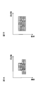
- FIG. 1A and 1B are diagrams for explaining an SS block.
- FIG. 2 is a diagram for explaining a procedure from initial access to connection establishment.
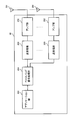
- FIG. 3 is a diagram for explaining resource allocation
- FIG. 3A is a diagram illustrating a case of an existing LTE system
- FIG. 3B is a diagram illustrating a case of an NR system.
- FIG. 4 is a diagram illustrating a method for the base station to instruct the user terminal of common search space (C-SS) resources
- FIG. 4A is a diagram for explaining the first method
- FIG. It is a figure for demonstrating the method of 2.
- FIG. FIG. 5 is a diagram illustrating an example of a schematic configuration of a wireless communication system according to an embodiment of the present invention.
- FIG. 6 is a diagram illustrating an example of the overall configuration of a radio base station according to an embodiment of the present invention.
- FIG. 7 is a diagram illustrating an example of a functional configuration of a radio base station according to an embodiment of the present invention.
- FIG. 8 is a diagram illustrating an example of the overall configuration of a user terminal according to an embodiment of the present invention.
- FIG. 9 is a diagram illustrating an example of a functional configuration of a user terminal according to an embodiment of the present invention.
- FIG. 10 is a diagram illustrating an example of a hardware configuration of a radio base station and a user terminal according to an embodiment of the present invention.
- the user terminal can detect at least time frequency synchronization and a cell identifier (cell ID) by detecting a synchronization signal (PSS / SSS).
- the user terminal receives a broadcast channel (broadcast channel (for example, PBCH)) including system information after acquiring the cell ID in synchronization with the network.
- a broadcast channel for example, PBCH
- SIB System Information Block
- PRACH Physical Random Access Channel
- the user terminal receives system information (broadcast information) necessary for downlink communication through an MIB (Master Information Block) transmitted through the broadcast channel (PBCH) or the like.
- the broadcast channel (LTE-PBCH) of the existing LTE system is transmitted by Subframe # 0 in each radio frame at a cycle of 10 msec in a center band of 1.4 MHz (center 6 RBs).
- SIB System Information Block
- PDSCH downlink shared data channel
- the allocation position of the synchronization signal (LTE-PSS / SSS) and the broadcast channel (LTE-PBCH) of the existing LTE system is fixed in the time resource and the frequency resource.
- the LTE-PSS / SSS and the broadcast channel are mapped and transmitted in the same frequency domain (for example, 6 RB of the center frequency).
- LTE-PSS / SSS and LTE-PBCH are transmitted from the radio base station with fixed resources, reception can be performed without special notification to the user terminal.
- a carrier also referred to as an NR carrier (cell)
- a synchronization signal and system information MIB and / or SIB
- a synchronization signal for example, NR-PSS and / or NR-SSS (hereinafter also referred to as NR-PSS / SSS)
- a broadcast channel for example, NR-PBCH
- RS reference signal
- SS block (synchronization signal block) can be composed of a plurality of consecutive OFDM symbols.
- a symbol for NR-PSS, a symbol for NR-SSS, and a symbol for NR-PBCH are continuously arranged.
- the NR-PBCH may be arranged in a plurality of symbols (for example, 2 symbols). In this case, one NR-PSS symbol, one NR-SSS symbol, and two NR-PBCH symbols are used as SS blocks. Is configured.
- the arrangement order of NR-PSS / SSS and NR-PBCH is not limited to this.
- NR-PSS / SSS and NR-PBCH may be configured to be mapped to the same frequency region (bandwidth) or may be configured to be mapped to different frequency regions. Further, the positional relationship between NR-PSS / SSS and NR-PBCH may be set by aligning the center frequency, or the center frequency may be set differently.
- the center frequency of the SS block may be regarded as the center frequency of NR-PSS / SSS and / or NR-PBCH, or may be set separately from the center frequency of NR-PSS / SSS and the center frequency of NR-PBCH. Good.
- the end of the SS block may be regarded as the end of NR-PSS / SSS and / or NR-PBCH, or set separately from the end of NR-PSS / SSS and the end of NR-PBCH. May be.
- a UE that can communicate with a continuous predetermined bandwidth (for example, 50 MHz) is allowed to connect to a carrier (NR carrier, also called NR-CC) that controls communication with a bandwidth of 100 MHz.
- NR carrier also called NR-CC
- a frequency range below a predetermined bandwidth is set for the user terminal, and the user terminal transmits and receives in the set frequency range.
- the frequency domain may be set for each user terminal (user terminal specific). Further, the same frequency region may be set in DL transmission and UL transmission, or different frequency regions may be set.
- CC component carriers
- one or a plurality of frequency regions specific to the user terminal may be set for each CC.
- FIG. 2 is a schematic diagram for explaining a procedure from initial access to connection establishment.
- the base station transmits the SS block (PSS / SSS, PBCH), and the user terminal detects the SS block (ST1). Further, the base station transmits system information to the user terminal (ST2).
- PSS / SSS, PBCH SS block
- ST1 system information
- the user terminal After that, the user terminal performs random access. That is, the user terminal transmits PRACH (message 1) to the base station (ST3), and after the base station receives the PRACH, RAR (Random Access Response) (message 2) is transmitted to the user terminal (ST4). Thereafter, message 3 is transmitted from the user terminal to the base station (ST5), and message 4 is transmitted from the base station to the user terminal (ST6).
- PRACH signalssage 1
- RAR Random Access Response
- downlink data (DL data) is transmitted from the base station to the user terminal
- uplink data (UL data) is transmitted from the user terminal to the base station (ST7, ST8).
- the user terminal performs the following operations.
- the user terminal performs the following operation, for example. -The user terminal detects the SS block. That is, the user terminal monitors the bandwidth of the SS block. -The user terminal receives system information. That is, the user terminal monitors the bandwidth at which system information is transmitted. -The user terminal performs random access. That is, the user terminal operates with the RACH bandwidth. After the RRC (Radio Resource Control) connection is established, the user terminal is set with a bandwidth specific to the user terminal for monitoring a U-SS (UE specific search space).
- RRC Radio Resource Control
- ⁇ Idle mode> In the idle mode, the user terminal performs the following operations, for example. A specific bandwidth for monitoring paging is set in the user terminal. A specific bandwidth for performing RRM (Radio Resource Management) measurement is set in the user terminal.
- RRM Radio Resource Management
- connection mode the user terminal performs the following operation, for example.
- a bandwidth unique to the user terminal for monitoring the U-SS and performing CSI measurement is set.
- a specific bandwidth for performing RRM measurement is set in the user terminal.
- DCI Downlink Control Information
- the DCI that schedules the SIB indicates the location of the PDSCH including the SIB.
- the DCI that schedules the RAR indicates the location of the PDSCH including the RAR.
- the UL transmission instruction (UL grant) included in the RAR indicates the position of the PUSCH for the random access message 3.
- the DCI that schedules the random access message 4 indicates the location of the PDSCH that includes the message 4. If the connection has been established, DCI that schedules downlink data or uplink data indicates the position of PDSCH or PUSCH. Further, the position of a user-specific search space for monitoring PDSCH or PUSCH may be indicated by DCI for scheduling SIB and / or DCI for random access.
- the frequency band (bandwidth) monitored by the user terminal as described above does not necessarily have to be the same in each of the above operations and may be different.
- the resource index is defined based on the carrier bandwidth. That is, resource allocation is performed using a common resource index for the above operations.
- the number of bits for resource allocation is also determined based on the carrier bandwidth. For example, if the carrier bandwidth is 20 MHz, the DL resource allocation type 0 has an RBG (Resource block group) size of 4 and the number of bits is 25, and the UL Resource allocation type 0 requires continuous allocation. The number of bits is 13 less than DL.
- FIG. 3 is a diagram for explaining resource allocation
- FIG. 3A is a diagram illustrating an example of an existing LTE system
- FIG. 3B is a diagram illustrating an example of an NR system.
- the synchronization signal (SS) and the broadcast channel (PBCH) are always set to the center (6 resource block (RB)) of the LTE carrier.
- a base station notifies a carrier frequency bandwidth to a user terminal by PBCH.
- the RB index starts from the resource block with the lowest carrier frequency.
- the user terminal when detecting up to the PBCH, the user terminal can recognize the end (edge) of the carrier frequency and can recognize which position the RB index indicates.
- the scheduling of each signal is controlled by resource allocation (for example, RB allocation) included in DCI, and the number of bits of resource allocation included in DCI is defined based on the carrier bandwidth.
- SS / PBCH for example, SS block
- SS bandwidth (12RB in FIG. 3B) and the PBCH bandwidth (24RB in FIG. 3B) may be different.
- the user terminal when a frequency band (frequency range) to be monitored is set for each user terminal, the user terminal does not need to monitor the entire broadband carrier bandwidth.
- the frequency band is expanded, if the same control method (for example, resource allocation method) as the existing LTE system is used as it is, the size of information (for example, resource allocation information) notified to the user terminal increases. And / or an increase in transmission / reception processing load in the user terminal may occur, and communication may not be performed properly.
- the present inventors have focused on the fact that in future communication systems, all user terminals do not necessarily use the entire carrier bandwidth, and control of resource allocation and the like can be controlled separately according to the operation of the user terminals. It was conceived that the bit size of the resource allocation information included in the information and / or the broadcast channel is set separately according to each downlink control information and / or the type of signal scheduled by the broadcast channel.
- an aspect of the user terminal is based on a receiving unit that receives downlink control information and / or a broadcast channel for scheduling a predetermined signal, and a resource allocation information included in the downlink control information and / or the broadcast channel. And a control unit for determining signal resource allocation, wherein the bit size of the resource allocation information included in the downlink control information and / or broadcast channel is set according to the type of the predetermined signal, respectively.
- the resource allocation information includes a combination of information indicating an allocation resource offset and information indicating a range, or information specifying a predetermined resource offset from a plurality of preset resource offsets. Hope to be included. Moreover, in the one aspect
- the RB allocation bit size is individually defined for each processing DCI.
- this processing includes SIB scheduling, RAR scheduling, message 3 scheduling in random access, message 4 scheduling in random access, DL / UL data scheduling, and the like.
- the DCI RB allocation bit sizes for each process may be set differently, or some processes may be set in common.
- the RB index including the granularity of RB allocation and / or the allocation range may be set differently. For example, some RB indexes of the DCI can be user-specific. In addition, the RB allocation ranges in different DCI (or PBCH) may partially or entirely overlap.
- Information necessary for determining the user-specific RB index is notified from the base station to the user terminal by RRC signaling or the like.
- examples of information necessary for determining a user-specific RB index include a user-specific indexing reference position, a bandwidth monitored by the user, and the like.
- a user terminal will assume that there are different DCI payload sizes (at least different RB allocation bit sizes) under various conditions.
- the RB allocation and the index reference position are individually defined in the DCI for each process.
- the user terminal determines the allocation resource of the common search space specified by the PBCH based on the resource allocation information included in the PBCH with the SS block position as a reference position. This is because, for example, when detecting the PBCH in the initial connection, only the SS block can be detected.
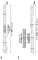
- FIG. 4 is a diagram illustrating a method for the base station to instruct the user terminal of common search space (C-SS) resources
- FIG. 4A is a diagram for explaining the first method
- FIG. It is a figure for demonstrating the method of 2.
- FIG. 4 is a diagram illustrating a method for the base station to instruct the user terminal of common search space (C-SS) resources
- the base station sets the frequency offset and frequency resource (bandwidth, range, or range) from the SS block (SSB) position, and the base station sets the frequency offset and frequency resource from the SS block position. It is a method of notifying. These frequency offsets and frequency resources are notified to the user terminal by PBCH. Or when already connected, you may notify a user terminal using higher layer signaling etc. In the first method, since the frequency offset and the frequency resource are notified using individual fields, the frequency offset and the frequency resource can be set flexibly.
- SSB SS block
- positions that are candidates for the common search space are determined in advance for the SS block, and the predetermined candidates are notified to the user terminal. For example, an index is added to each candidate position of the common search space (index 0 to 4 in FIG. 4B), and the base station notifies the user terminal of the predetermined index. These index information is notified to the user terminal by PBCH. Or when already connected, you may notify a user terminal using higher layer signaling etc.
- the frequency offset and the frequency resource are notified using one field by notifying the index, the number of bits used for the notification can be reduced.
- the user terminal determines an allocation resource of system information (for example, SIB) designated by DCI based on resource allocation information included in the DCI with reference to a predetermined position.
- the predetermined position may be an SS block position and / or a PDCCH position where SIB is scheduled. Note that the number of bits of the resource allocation information included in the DCI can be defined separately from other communication types.
- the first method is a method in which the base station sets the frequency offset and frequency resource (bandwidth) from the SS block position or PDCCH position, and the base station notifies the frequency offset and frequency resource from the reference position. .
- These frequency offsets and frequency resources may be notified by higher layer signaling.
- the frequency offset and the frequency resource can be set flexibly.
- the second method is a method in which an SIB is transmitted in advance, an index is added, and the base station notifies the user terminal of this index.
- Information on frequency indexes corresponding to these indexes and / or indexes may be signaled by higher layer signaling.
- the frequency offset and the frequency resource are notified using one field by notifying the index, the number of bits used for the notification can be reduced.
- Examples of the reference position of the allocated resource in the random access procedure include the SS block position, the SIB position, or the carrier center based on the carrier information notified by the SIB.
- the number of bits of the resource allocation information included in the DCI corresponding to each message (messages 1 to 4) and / or the reference position applied to the resource allocation information may be set separately or set in common. May be.
- the message 1 and the message 3 may be set in common, and the message 2 and the message 4 may be set in common.
- a position scheduling signal and / or a channel (eg, PDCCH) position may be used as the reference position.
- a position scheduling signal and / or a channel (eg, PDCCH) position may be used as the reference position.
- PDCCH Physical Downlink Control Channel
- the position of SIB or common DCI
- the position of DCI (PDCCH) that schedules RAR is used as a reference position.
- the position of RAR is the reference position.
- the position of DCI (PDCCH) where the message 4 is scheduled is set as a reference position.
- the resource allocation information of each message may be notified to the user terminal using the first method or the second method described above.
- the user terminal includes the allocation resource of PDSCH including a predetermined signal (user data) specified by DCI in DCI using at least one of SS block position, PDCCH position for scheduling PDSCH, and predetermined position of carrier as a reference position. Judgment is made based on the resource allocation information.
- the user terminal includes an allocation resource of UL data (for example, PUSCH) specified by DCI in DCI using at least one of an SS block position, a PDCCH position for scheduling PUSCH, and a predetermined position of a carrier as a reference position. Judgment is made based on the resource allocation information.
- the reference position of the allocated resource can be the center or edge of the user-specific bandwidth (bandwidth set when performing user-specific indexing (UE-specific indexing)).
- the reference position of the user-specific bandwidth instruction and the user-specific search space instruction may be the SS block, the center of the system bandwidth, or the edge of the system bandwidth.
- the user data resource allocation information may be notified to the user terminal using the first method or the second method described above.
- the DCI that schedules data includes information on the frequency offset and the frequency resource (bandwidth) and notifies the user terminal (first method).
- the first method can be suitably applied when DL data and / or UL data are allocated to continuous resources.
- the index including the information on the presence / absence of allocation is notified to the user terminal using a bitmap (second method).
- a bitmap For example, it is also conceivable that DL data and / or UL data are allocated to non-contiguous resources (for example, RB) in a predetermined frequency band.
- non-contiguous resources for example, a plurality of RBs
- the resource unit notified by the bitmap is not limited to the RB unit, and may be another resource unit (for example, RBG unit).
- wireless communication system Wireless communication system
- communication is performed using any one or a combination of the wireless communication methods according to the above embodiments of the present invention.
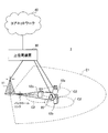
- FIG. 5 is a diagram illustrating an example of a schematic configuration of a wireless communication system according to an embodiment of the present invention.
- carrier aggregation (CA) and / or dual connectivity (DC) in which a plurality of basic frequency blocks (component carriers) each having a system bandwidth (for example, 20 MHz) of the LTE system as one unit are applied. can do.
- DC dual connectivity
- the wireless communication system 1 includes LTE (Long Term Evolution), LTE-A (LTE-Advanced), LTE-B (LTE-Beyond), SUPER 3G, IMT-Advanced 4G (4th generation mobile communication system), 5G. (5th generation mobile communication system), NR (New Radio), FRA (Future Radio Access), New-RAT (Radio Access Technology), etc., or a system that realizes these.
- the radio communication system 1 includes a radio base station 11 that forms a macro cell C1 having a relatively wide coverage, and a radio base station 12 (12a-12c) that is arranged in the macro cell C1 and forms a small cell C2 that is narrower than the macro cell C1. It is equipped with. Moreover, the user terminal 20 is arrange
- the user terminal 20 can be connected to both the radio base station 11 and the radio base station 12. It is assumed that the user terminal 20 uses the macro cell C1 and the small cell C2 at the same time using CA or DC. Moreover, the user terminal 20 may apply CA or DC using a plurality of cells (CC) (for example, 5 or less CCs, 6 or more CCs).
- CC cells
- Communication between the user terminal 20 and the radio base station 11 can be performed using a carrier having a relatively low frequency band (for example, 2 GHz) and a narrow bandwidth (also referred to as an existing carrier or a legacy carrier).
- a carrier having a relatively high frequency band for example, 3.5 GHz, 5 GHz, etc.
- the same carrier may be used.
- the configuration of the frequency band used by each radio base station is not limited to this.
- the user terminal 20 can perform communication using time division duplex (TDD) and / or frequency division duplex (FDD) in each cell.
- TDD time division duplex
- FDD frequency division duplex
- a single neurology may be applied, or a plurality of different neurology may be applied.
- the wireless base station 11 and the wireless base station 12 are connected by wire (for example, optical fiber compliant with CPRI (Common Public Radio Interface), X2 interface, etc.) or wirelessly. May be.
- the radio base station 11 and each radio base station 12 are connected to the higher station apparatus 30 and connected to the core network 40 via the higher station apparatus 30.
- the upper station device 30 includes, for example, an access gateway device, a radio network controller (RNC), a mobility management entity (MME), and the like, but is not limited thereto.
- RNC radio network controller
- MME mobility management entity
- Each radio base station 12 may be connected to the higher station apparatus 30 via the radio base station 11.
- the radio base station 11 is a radio base station having a relatively wide coverage, and may be called a macro base station, an aggregation node, an eNB (eNodeB), a transmission / reception point, or the like.
- the radio base station 12 is a radio base station having local coverage, and includes a small base station, a micro base station, a pico base station, a femto base station, a HeNB (Home eNodeB), an RRH (Remote Radio Head), and transmission / reception. It may be called a point.
- the radio base stations 11 and 12 are not distinguished, they are collectively referred to as a radio base station 10.
- Each user terminal 20 is a terminal that supports various communication schemes such as LTE and LTE-A, and may include not only a mobile communication terminal (mobile station) but also a fixed communication terminal (fixed station).
- orthogonal frequency division multiple access (OFDMA) is applied to the downlink, and single carrier-frequency division multiple access (SC-FDMA) is used for the uplink.
- SC-FDMA single carrier-frequency division multiple access
- Frequency Division Multiple Access and / or OFDMA is applied.
- OFDMA is a multi-carrier transmission scheme that performs communication by dividing a frequency band into a plurality of narrow frequency bands (subcarriers) and mapping data to each subcarrier.
- SC-FDMA is a single carrier transmission in which the system bandwidth is divided into bands each composed of one or continuous resource blocks for each terminal, and a plurality of terminals use different bands to reduce interference between terminals. It is a method.
- the uplink and downlink radio access schemes are not limited to these combinations, and other radio access schemes may be used.
- downlink channels include a downlink shared channel (PDSCH) shared by each user terminal 20, a broadcast channel (PBCH: Physical Broadcast Channel), a downlink L1 / L2 control channel, and the like. Used. User data, higher layer control information, SIB (System Information Block), etc. are transmitted by PDSCH. Moreover, MIB (Master Information Block) is transmitted by PBCH.
- PDSCH downlink shared channel
- PBCH Physical Broadcast Channel
- SIB System Information Block
- MIB Master Information Block
- Downlink L1 / L2 control channels include PDCCH (Physical Downlink Control Channel), EPDCCH (Enhanced Physical Downlink Control Channel), PCFICH (Physical Control Format Indicator Channel), PHICH (Physical Hybrid-ARQ Indicator Channel), and the like.
- Downlink control information (DCI: Downlink Control Information) including PDSCH and / or PUSCH scheduling information is transmitted by the PDCCH.
- scheduling information may be notified by DCI.
- DCI for scheduling DL data reception may be referred to as DL assignment
- DCI for scheduling UL data transmission may be referred to as UL grant.
- the number of OFDM symbols used for PDCCH is transmitted by PCFICH.
- the PHICH transmits HARQ (Hybrid Automatic Repeat reQuest) delivery confirmation information (for example, retransmission control information, HARQ-ACK, ACK / NACK, etc.) to the PUSCH.
- HARQ Hybrid Automatic Repeat reQuest
- EPDCCH is frequency-division multiplexed with PDSCH (downlink shared data channel), and is used for transmission of DCI and the like in the same manner as PDCCH.
- an uplink shared channel (PUSCH) shared by each user terminal 20
- an uplink control channel (PUCCH: Physical Uplink Control Channel)
- a random access channel (PRACH: Physical Random Access Channel)
- User data, higher layer control information, etc. are transmitted by PUSCH.
- downlink radio quality information CQI: Channel Quality Indicator
- delivery confirmation information SR
- scheduling request etc.
- a random access preamble for establishing connection with the cell is transmitted by the PRACH.
- a cell-specific reference signal CRS
- CSI-RS channel state information reference signal
- DMRS demodulation reference signal
- PRS Positioning Reference Signal
- a measurement reference signal SRS: Sounding Reference Signal
- a demodulation reference signal DMRS
- the DMRS may be referred to as a user terminal specific reference signal (UE-specific Reference Signal). Further, the transmitted reference signal is not limited to these.
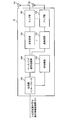
- FIG. 6 is a diagram illustrating an example of the overall configuration of a radio base station according to an embodiment of the present invention.
- the radio base station 10 includes a plurality of transmission / reception antennas 101, an amplifier unit 102, a transmission / reception unit 103, a baseband signal processing unit 104, a call processing unit 105, and a transmission path interface 106.
- the transmission / reception antenna 101, the amplifier unit 102, and the transmission / reception unit 103 may each be configured to include one or more.
- User data transmitted from the radio base station 10 to the user terminal 20 via the downlink is input from the higher station apparatus 30 to the baseband signal processing unit 104 via the transmission path interface 106.
- PDCP Packet Data Convergence Protocol
- RLC Radio Link Control
- MAC Medium Access
- Retransmission control for example, HARQ transmission processing
- scheduling transmission format selection, channel coding, Inverse Fast Fourier Transform (IFFT) processing, precoding processing, and other transmission processing
- IFFT Inverse Fast Fourier Transform
- precoding processing precoding processing, and other transmission processing
- the downlink control signal is also subjected to transmission processing such as channel coding and inverse fast Fourier transform, and is transferred to the transmission / reception unit 103.
- the transmission / reception unit 103 converts the baseband signal output by precoding for each antenna from the baseband signal processing unit 104 to a radio frequency band and transmits the converted signal.
- the radio frequency signal frequency-converted by the transmission / reception unit 103 is amplified by the amplifier unit 102 and transmitted from the transmission / reception antenna 101.
- the transmission / reception unit 103 can be configured by a transmitter / receiver, a transmission / reception circuit, or a transmission / reception device, which is described based on common recognition in the technical field according to the present invention.
- the transmission / reception part 103 may be comprised as an integral transmission / reception part, and may be comprised from a transmission part and a receiving part.
- the radio frequency signal received by the transmission / reception antenna 101 is amplified by the amplifier unit 102.
- the transmission / reception unit 103 receives the uplink signal amplified by the amplifier unit 102.
- the transmission / reception unit 103 converts the frequency of the received signal into a baseband signal and outputs it to the baseband signal processing unit 104.
- the baseband signal processing unit 104 performs fast Fourier transform (FFT) processing, inverse discrete Fourier transform (IDFT: Inverse Discrete Fourier Transform) processing, and error correction on user data included in the input upstream signal.
- FFT fast Fourier transform
- IDFT inverse discrete Fourier transform
- Decoding, MAC retransmission control reception processing, RLC layer and PDCP layer reception processing are performed and transferred to the upper station apparatus 30 via the transmission path interface 106.
- the call processor 105 performs communication channel call processing (setting, release, etc.), status management of the radio base station 10, radio resource management, and the like.
- the transmission path interface 106 transmits and receives signals to and from the higher station apparatus 30 via a predetermined interface.
- the transmission path interface 106 transmits / receives signals (backhaul signaling) to / from other radio base stations 10 via an interface between base stations (for example, an optical fiber compliant with CPRI (Common Public Radio Interface), X2 interface). May be.
- CPRI Common Public Radio Interface
- X2 interface May be.
- the transmission / reception unit 103 transmits one or more synchronization signal blocks (SS blocks) including a synchronization signal (for example, NR-PSS, NR-SSS, etc.) and a broadcast channel (for example, NR-PBCH).
- SS blocks synchronization signal blocks
- the transceiver 103 may transmit NR-PBCH having the same content and / or configuration using a plurality of different SS blocks.
- the transmission / reception unit 103 transmits resource allocation information to the user terminal.
- resource allocation information include a bitmap indicating an index of allocated resources, a reference position in the frequency domain, a frequency bandwidth, an offset from the reference position, and the like.
- FIG. 7 is a diagram illustrating an example of a functional configuration of a radio base station according to an embodiment of the present invention.
- the functional block of the characteristic part in this embodiment is mainly shown, and it may be assumed that the wireless base station 10 also has other functional blocks necessary for wireless communication.
- the baseband signal processing unit 104 includes at least a control unit (scheduler) 301, a transmission signal generation unit 302, a mapping unit 303, a reception signal processing unit 304, and a measurement unit 305. These configurations may be included in the radio base station 10, and a part or all of the configurations may not be included in the baseband signal processing unit 104.
- the control unit (scheduler) 301 controls the entire radio base station 10.
- the control part 301 can be comprised from the controller, the control circuit, or control apparatus demonstrated based on the common recognition in the technical field which concerns on this invention.
- the control unit 301 controls, for example, signal generation in the transmission signal generation unit 302, signal allocation in the mapping unit 303, and the like.
- the control unit 301 also controls signal reception processing in the reception signal processing unit 304, signal measurement in the measurement unit 305, and the like.
- the control unit 301 schedules system information, downlink data signals (for example, signals transmitted by PDSCH), downlink control signals (for example, signals transmitted by PDCCH and / or EPDCCH, delivery confirmation information, etc.) (for example, resource Control).
- the control unit 301 controls generation of a downlink control signal, a downlink data signal, and the like based on a result of determining whether or not retransmission control is necessary for the uplink data signal.
- the control unit 301 controls scheduling of synchronization signals (for example, PSS (Primary Synchronization Signal) / SSS (Secondary Synchronization Signal)), downlink reference signals (for example, CRS, CSI-RS, DMRS) and the like.
- control unit 301 includes an uplink data signal (for example, a signal transmitted on PUSCH), an uplink control signal (for example, a signal transmitted on PUCCH and / or PUSCH, delivery confirmation information, etc.), a random access preamble (for example, Scheduling of the uplink reference signal and the like.
- uplink data signal for example, a signal transmitted on PUSCH
- uplink control signal for example, a signal transmitted on PUCCH and / or PUSCH, delivery confirmation information, etc.
- a random access preamble for example, Scheduling of the uplink reference signal and the like.
- the control unit 301 sets the bit size of the resource allocation information included in DCI and / or PBCH according to the type of the predetermined signal.
- the type of the predetermined signal is, for example, a common search space included in the PBCH, system information, a signal in a random access procedure, user data, and the like. Of course, the type of the predetermined signal is not limited to these.
- the transmission signal generation unit 302 generates a downlink signal (downlink control signal, downlink data signal, downlink reference signal, etc.) based on an instruction from the control unit 301, and outputs it to the mapping unit 303.
- the transmission signal generation unit 302 can be configured by a signal generator, a signal generation circuit, or a signal generation device described based on common recognition in the technical field according to the present invention.
- the transmission signal generation unit 302 generates, for example, a DL assignment for notifying downlink data allocation information and / or a UL grant for notifying uplink data allocation information based on an instruction from the control unit 301.
- the DL assignment and UL grant are both DCI and follow the DCI format.
- the downlink data signal is subjected to coding processing and modulation processing according to a coding rate, a modulation scheme, and the like determined based on channel state information (CSI: Channel State Information) from each user terminal 20.
- CSI Channel State Information
- the mapping unit 303 maps the downlink signal generated by the transmission signal generation unit 302 to a predetermined radio resource based on an instruction from the control unit 301, and outputs it to the transmission / reception unit 103.
- the mapping unit 303 can be configured by a mapper, a mapping circuit, or a mapping device described based on common recognition in the technical field according to the present invention.
- the reception signal processing unit 304 performs reception processing (for example, demapping, demodulation, decoding, etc.) on the reception signal input from the transmission / reception unit 103.
- the received signal is, for example, an uplink signal (uplink control signal, uplink data signal, uplink reference signal, etc.) transmitted from the user terminal 20.
- the reception signal processing unit 304 can be configured by a signal processor, a signal processing circuit, or a signal processing device described based on common recognition in the technical field according to the present invention.
- the reception signal processing unit 304 outputs the information decoded by the reception processing to the control unit 301. For example, when receiving PUCCH including HARQ-ACK, HARQ-ACK is output to control section 301.
- the reception signal processing unit 304 outputs the reception signal and / or the signal after reception processing to the measurement unit 305.
- the measurement unit 305 performs measurement on the received signal.
- the measurement part 305 can be comprised from the measuring device, measurement circuit, or measurement apparatus demonstrated based on common recognition in the technical field which concerns on this invention.
- the measurement unit 305 may perform RRM (Radio Resource Management) measurement, CSI (Channel State Information) measurement, and the like based on the received signal.
- the measurement unit 305 includes received power (for example, RSRP (Reference Signal Received Power)), received quality (for example, RSRQ (Reference Signal Received Quality), SINR (Signal to Interference plus Noise Ratio), SNR (Signal to Noise Ratio)).
- Signal strength for example, RSSI (Received Signal Strength Indicator)
- propagation path information for example, CSI
- the measurement result may be output to the control unit 301.
- FIG. 8 is a diagram illustrating an example of the overall configuration of a user terminal according to an embodiment of the present invention.
- the user terminal 20 includes a plurality of transmission / reception antennas 201, an amplifier unit 202, a transmission / reception unit 203, a baseband signal processing unit 204, and an application unit 205.
- the transmission / reception antenna 201, the amplifier unit 202, and the transmission / reception unit 203 may each be configured to include one or more.
- the radio frequency signal received by the transmission / reception antenna 201 is amplified by the amplifier unit 202.
- the transmission / reception unit 203 receives the downlink signal amplified by the amplifier unit 202.
- the transmission / reception unit 203 converts the frequency of the received signal into a baseband signal and outputs it to the baseband signal processing unit 204.
- the transmission / reception unit 203 can be configured by a transmitter / receiver, a transmission / reception circuit, or a transmission / reception device described based on common recognition in the technical field according to the present invention.
- the transmission / reception unit 203 may be configured as an integral transmission / reception unit, or may be configured from a transmission unit and a reception unit.
- the baseband signal processing unit 204 performs FFT processing, error correction decoding, retransmission control reception processing, and the like on the input baseband signal.
- the downlink user data is transferred to the application unit 205.
- the application unit 205 performs processing related to layers higher than the physical layer and the MAC layer. Also, broadcast information of downlink data may be transferred to the application unit 205.
- uplink user data is input from the application unit 205 to the baseband signal processing unit 204.
- the baseband signal processing unit 204 performs transmission / reception units for retransmission control (for example, HARQ transmission processing), channel coding, precoding, discrete Fourier transform (DFT) processing, IFFT processing, and the like.
- the transmission / reception unit 203 converts the baseband signal output from the baseband signal processing unit 204 into a radio frequency band and transmits it.
- the radio frequency signal frequency-converted by the transmission / reception unit 203 is amplified by the amplifier unit 202 and transmitted from the transmission / reception antenna 201.
- the transmission / reception unit 203 receives one or more synchronization signal blocks (SS blocks) including a synchronization signal (for example, NR-PSS, NR-SSS, etc.) and a broadcast channel (for example, NR-PBCH).
- SS blocks synchronization signal blocks
- a synchronization signal for example, NR-PSS, NR-SSS, etc.
- a broadcast channel for example, NR-PBCH.
- the transmission / reception unit 203 may combine and receive the NR-PBCH included in each of a plurality of different SS blocks based on information related to combined reception of the NR-PBCH.
- FIG. 9 is a diagram illustrating an example of a functional configuration of a user terminal according to an embodiment of the present invention.
- the functional block of the characteristic part in this embodiment is mainly shown, and it may be assumed that the user terminal 20 also has other functional blocks necessary for wireless communication.
- the baseband signal processing unit 204 included in the user terminal 20 includes at least a control unit 401, a transmission signal generation unit 402, a mapping unit 403, a reception signal processing unit 404, and a measurement unit 405. Note that these configurations may be included in the user terminal 20, and some or all of the configurations may not be included in the baseband signal processing unit 204.
- the control unit 401 controls the entire user terminal 20.
- the control unit 401 can be composed of a controller, a control circuit, or a control device described based on common recognition in the technical field according to the present invention.
- the control unit 401 controls, for example, signal generation in the transmission signal generation unit 402, signal allocation in the mapping unit 403, and the like.
- the control unit 401 also controls signal reception processing in the reception signal processing unit 404, signal measurement in the measurement unit 405, and the like.
- the control unit 401 acquires the downlink control signal and the downlink data signal transmitted from the radio base station 10 from the reception signal processing unit 404.
- the control unit 401 controls the generation of the uplink control signal and / or the uplink data signal based on the result of determining the necessity of retransmission control for the downlink control signal and / or the downlink data signal.
- the control unit 401 determines resource allocation of a predetermined signal based on resource allocation information included in DCI and / or PBCH.
- the control unit 401 determines the common search space allocation resource specified by the PBCH based on the resource allocation information included in the PBCH with the SS block position as a reference position.
- the control unit 401 allocates PDSCH allocation resources including a predetermined signal specified by DCI, and includes resource allocation included in DCI using at least one of an SS block position, a PDCCH position for scheduling PDSCH, and a predetermined position of a carrier as a reference position. Judgment based on information.
- the control unit 401 determines the allocation resource of the SIB specified by the DCI based on the resource allocation information included in the DCI using the SS block position and / or the PDCCH position for scheduling the SIB as a reference position.
- the transmission signal generation unit 402 generates an uplink signal (uplink control signal, uplink data signal, uplink reference signal, etc.) based on an instruction from the control unit 401 and outputs the uplink signal to the mapping unit 403.
- the transmission signal generation unit 402 can be configured by a signal generator, a signal generation circuit, or a signal generation device described based on common recognition in the technical field according to the present invention.
- the transmission signal generation unit 402 generates an uplink control signal related to delivery confirmation information, channel state information (CSI), and the like based on an instruction from the control unit 401, for example. In addition, the transmission signal generation unit 402 generates an uplink data signal based on an instruction from the control unit 401. For example, the transmission signal generation unit 402 is instructed by the control unit 401 to generate an uplink data signal when the UL grant is included in the downlink control signal notified from the radio base station 10.
- CSI channel state information
- the mapping unit 403 maps the uplink signal generated by the transmission signal generation unit 402 to a radio resource based on an instruction from the control unit 401, and outputs the radio signal to the transmission / reception unit 203.
- the mapping unit 403 can be configured by a mapper, a mapping circuit, or a mapping device described based on common recognition in the technical field according to the present invention.
- the reception signal processing unit 404 performs reception processing (for example, demapping, demodulation, decoding, etc.) on the reception signal input from the transmission / reception unit 203.
- the received signal is, for example, a downlink signal (downlink control signal, downlink data signal, downlink reference signal, etc.) transmitted from the radio base station 10.
- the reception signal processing unit 404 can be configured by a signal processor, a signal processing circuit, or a signal processing device described based on common recognition in the technical field according to the present invention. Further, the reception signal processing unit 404 can constitute a reception unit according to the present invention.
- the reception signal processing unit 404 outputs the information decoded by the reception processing to the control unit 401.
- the reception signal processing unit 404 outputs, for example, broadcast information, system information, RRC signaling, DCI, and the like to the control unit 401.
- the reception signal processing unit 404 outputs the reception signal and / or the signal after reception processing to the measurement unit 405.
- the measurement unit 405 performs measurement on the received signal.
- the measurement part 405 can be comprised from the measuring device, measurement circuit, or measurement apparatus demonstrated based on common recognition in the technical field which concerns on this invention.
- the measurement unit 405 may perform RRM measurement, CSI measurement, and the like based on the received signal.
- the measurement unit 405 may measure reception power (for example, RSRP), reception quality (for example, RSRQ, SINR, SNR), signal strength (for example, RSSI), propagation path information (for example, CSI), and the like.
- the measurement result may be output to the control unit 401.
- each functional block (components) are realized by any combination of hardware and / or software.
- the method for realizing each functional block is not particularly limited. That is, each functional block may be realized using one device physically and / or logically coupled, or directly and / or two or more devices physically and / or logically separated. Alternatively, it may be realized indirectly by connecting (for example, using wired and / or wireless) and using these plural devices.
- a radio base station, a user terminal, etc. in an embodiment of the present invention may function as a computer that performs processing of the radio communication method of the present invention.
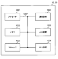
- FIG. 10 is a diagram illustrating an example of a hardware configuration of a radio base station and a user terminal according to an embodiment of the present invention.
- the wireless base station 10 and the user terminal 20 described above may be physically configured as a computer device including a processor 1001, a memory 1002, a storage 1003, a communication device 1004, an input device 1005, an output device 1006, a bus 1007, and the like. Good.
- the term “apparatus” can be read as a circuit, a device, a unit, or the like.
- the hardware configurations of the radio base station 10 and the user terminal 20 may be configured to include one or a plurality of each device illustrated in the figure, or may be configured not to include some devices.
- processor 1001 may be implemented by one or more chips.
- Each function in the radio base station 10 and the user terminal 20 is calculated by causing the processor 1001 to perform calculations by reading predetermined software (programs) on hardware such as the processor 1001 and the memory 1002, for example, via the communication device 1004. This is realized by controlling communication and controlling reading and / or writing of data in the memory 1002 and the storage 1003.
- the processor 1001 controls the entire computer by operating an operating system, for example.
- the processor 1001 may be configured by a central processing unit (CPU) including an interface with peripheral devices, a control device, an arithmetic device, a register, and the like.
- CPU central processing unit
- the baseband signal processing unit 104 (204) and the call processing unit 105 described above may be realized by the processor 1001.
- the processor 1001 reads programs (program codes), software modules, data, and the like from the storage 1003 and / or the communication device 1004 to the memory 1002, and executes various processes according to these.
- programs program codes
- software modules software modules
- data data
- the control unit 401 of the user terminal 20 may be realized by a control program stored in the memory 1002 and operating in the processor 1001, and may be realized similarly for other functional blocks.
- the memory 1002 is a computer-readable recording medium such as a ROM (Read Only Memory), an EPROM (Erasable Programmable ROM), an EEPROM (Electrically EPROM), a RAM (Random Access Memory), or any other suitable storage medium. It may be configured by one.
- the memory 1002 may be called a register, a cache, a main memory (main storage device), or the like.
- the memory 1002 can store programs (program codes), software modules, and the like that can be executed to implement the wireless communication method according to an embodiment of the present invention.
- the storage 1003 is a computer-readable recording medium such as a flexible disk, a floppy (registered trademark) disk, a magneto-optical disk (for example, a compact disk (CD-ROM (Compact Disc ROM)), a digital versatile disk, Blu-ray® disk), removable disk, hard disk drive, smart card, flash memory device (eg, card, stick, key drive), magnetic stripe, database, server, or other suitable storage medium It may be constituted by.
- the storage 1003 may be referred to as an auxiliary storage device.
- the communication device 1004 is hardware (transmission / reception device) for performing communication between computers via a wired and / or wireless network, and is also referred to as a network device, a network controller, a network card, a communication module, or the like.
- the communication device 1004 includes, for example, a high-frequency switch, a duplexer, a filter, a frequency synthesizer, etc., in order to realize frequency division duplex (FDD) and / or time division duplex (TDD). It may be configured.
- FDD frequency division duplex
- TDD time division duplex
- the transmission / reception antenna 101 (201), the amplifier unit 102 (202), the transmission / reception unit 103 (203), the transmission path interface 106, and the like described above may be realized by the communication device 1004.
- the input device 1005 is an input device (for example, a keyboard, a mouse, a microphone, a switch, a button, a sensor, etc.) that accepts an input from the outside.
- the output device 1006 is an output device (for example, a display, a speaker, an LED (Light Emitting Diode) lamp, etc.) that performs output to the outside.
- the input device 1005 and the output device 1006 may have an integrated configuration (for example, a touch panel).
- the devices such as the processor 1001 and the memory 1002 are connected by a bus 1007 for communicating information.
- the bus 1007 may be configured using a single bus, or may be configured using a different bus for each device.
- the radio base station 10 and the user terminal 20 include a microprocessor, a digital signal processor (DSP), an ASIC (Application Specific Integrated Circuit), a PLD (Programmable Logic Device), an FPGA (Field Programmable Gate Array), and the like. It may be configured including hardware, and a part or all of each functional block may be realized using the hardware. For example, the processor 1001 may be implemented using at least one of these hardware.
- DSP digital signal processor
- ASIC Application Specific Integrated Circuit
- PLD Programmable Logic Device
- FPGA Field Programmable Gate Array
- the channel and / or symbol may be a signal (signaling).
- the signal may be a message.
- the reference signal may be abbreviated as RS (Reference Signal), and may be referred to as a pilot, a pilot signal, or the like depending on an applied standard.
- a component carrier CC: Component Carrier
- CC Component Carrier
- the radio frame may be configured by one or a plurality of periods (frames) in the time domain.
- Each of the one or more periods (frames) constituting the radio frame may be referred to as a subframe.
- a subframe may be composed of one or more slots in the time domain.
- the subframe may have a fixed time length (eg, 1 ms) that does not depend on the neurology.
- the slot may be configured by one or a plurality of symbols (OFDM (Orthogonal Frequency Division Multiplexing) symbol, SC-FDMA (Single Carrier Frequency Division Multiple Access) symbol, etc.) in the time domain.
- the slot may be a time unit based on the numerology.
- the slot may include a plurality of mini slots. Each minislot may be configured with one or more symbols in the time domain. The minislot may also be called a subslot.
- Radio frame, subframe, slot, minislot, and symbol all represent time units when transmitting signals. Different names may be used for the radio frame, subframe, slot, minislot, and symbol.
- one subframe may be called a transmission time interval (TTI)
- TTI transmission time interval
- a plurality of consecutive subframes may be called a TTI
- TTI slot or one minislot
- a unit representing TTI may be called a slot, a minislot, or the like instead of a subframe.
- TTI means, for example, a minimum time unit for scheduling in wireless communication.
- a radio base station performs scheduling for assigning radio resources (frequency bandwidth, transmission power, etc. that can be used in each user terminal) to each user terminal in units of TTI.
- the definition of TTI is not limited to this.
- the TTI may be a transmission time unit of a channel-encoded data packet (transport block), a code block, and / or a code word, or may be a processing unit such as scheduling or link adaptation.
- a time interval for example, the number of symbols
- a transport block, a code block, and / or a code word is actually mapped may be shorter than the TTI.
- one or more TTIs may be the minimum scheduling unit. Further, the number of slots (the number of mini-slots) constituting the minimum time unit of the scheduling may be controlled.
- a TTI having a time length of 1 ms may be called a normal TTI (TTI in LTE Rel. 8-12), a normal TTI, a long TTI, a normal subframe, a normal subframe, or a long subframe.
- a TTI shorter than a normal TTI may be called a shortened TTI, a short TTI, a partial TTI (partial or fractional TTI), a shortened subframe, a short subframe, a minislot, or a subslot.
- a long TTI (eg, normal TTI, subframe, etc.) may be read as a TTI having a time length exceeding 1 ms, and a short TTI (eg, shortened TTI) is less than the TTI length of the long TTI and 1 ms. It may be replaced with a TTI having the above TTI length.
- a resource block is a resource allocation unit in the time domain and the frequency domain, and may include one or a plurality of continuous subcarriers (subcarriers) in the frequency domain. Further, the RB may include one or a plurality of symbols in the time domain, and may have a length of 1 slot, 1 mini slot, 1 subframe, or 1 TTI. One TTI and one subframe may each be composed of one or a plurality of resource blocks.
- One or more RBs include physical resource blocks (PRB), sub-carrier groups (SCG), resource element groups (REG), PRB pairs, RB pairs, etc. May be called.
- the resource block may be configured by one or a plurality of resource elements (RE: Resource Element).
- RE Resource Element
- 1RE may be a radio resource region of 1 subcarrier and 1 symbol.
- the structure of the above-described radio frame, subframe, slot, minislot, symbol, etc. is merely an example.
- the number of subframes included in a radio frame, the number of slots per subframe or radio frame, the number of minislots included in the slot, the number of symbols and RBs included in the slot or minislot, and the RB The number of subcarriers, the number of symbols in the TTI, the symbol length, the cyclic prefix (CP) length, and the like can be variously changed.
- the information, parameters, and the like described in this specification may be expressed using absolute values, may be expressed using relative values from a predetermined value, or other corresponding information may be used. May be represented.
- the radio resource may be indicated by a predetermined index.
- names used for parameters and the like are not limited names in any way.
- various channels PUCCH (Physical Uplink Control Channel), PDCCH (Physical Downlink Control Channel), etc.
- information elements can be identified by any suitable name, so the various channels and information elements assigned to them.
- the name is not limited in any way.
- information, signals, etc. can be output from the upper layer to the lower layer and / or from the lower layer to the upper layer.
- Information, signals, and the like may be input / output via a plurality of network nodes.
- the input / output information, signals, etc. may be stored in a specific location (for example, a memory) or may be managed using a management table. Input / output information, signals, and the like can be overwritten, updated, or added. The output information, signals, etc. may be deleted. Input information, signals, and the like may be transmitted to other devices.
- information notification includes physical layer signaling (eg, downlink control information (DCI), uplink control information (UCI)), upper layer signaling (eg, RRC (Radio Resource Control) signaling), It may be implemented by broadcast information (Master Information Block (MIB), System Information Block (SIB), etc.), MAC (Medium Access Control) signaling), other signals, or a combination thereof.
- DCI downlink control information
- UCI uplink control information
- RRC Radio Resource Control
- MIB Master Information Block
- SIB System Information Block
- MAC Medium Access Control
- the physical layer signaling may be referred to as L1 / L2 (Layer 1 / Layer 2) control information (L1 / L2 control signal), L1 control information (L1 control signal), or the like.
- the RRC signaling may be referred to as an RRC message, and may be, for example, an RRC connection setup (RRCConnectionSetup) message, an RRC connection reconfiguration (RRCConnectionReconfiguration) message, or the like.
- the MAC signaling may be notified using, for example, a MAC control element (MAC CE (Control Element)).
- notification of predetermined information is not limited to explicit notification, but implicitly (for example, by not performing notification of the predetermined information or other information) May be performed).
- the determination may be performed by a value represented by 1 bit (0 or 1), or may be performed by a boolean value represented by true or false.
- the comparison may be performed by numerical comparison (for example, comparison with a predetermined value).
- software, instructions, information, etc. may be sent and received via a transmission medium.
- software can use websites, servers using wired technology (coaxial cable, fiber optic cable, twisted pair, digital subscriber line (DSL), etc.) and / or wireless technology (infrared, microwave, etc.) , Or other remote sources, these wired and / or wireless technologies are included within the definition of transmission media.
- system and “network” used in this specification are used interchangeably.
- base station BS
- radio base station eNB
- gNB gNodeB
- cell gNodeB
- cell group a base station
- carrier a base station
- a base station may also be called in terms such as a fixed station, NodeB, eNodeB (eNB), access point, transmission point, reception point, femtocell, and small cell.
- the base station can accommodate one or a plurality of (for example, three) cells (also called sectors). If the base station accommodates multiple cells, the entire coverage area of the base station can be partitioned into multiple smaller areas, each smaller area being a base station subsystem (eg, an indoor small base station (RRH: The term “cell” or “sector” refers to part or all of the coverage area of a base station and / or base station subsystem that provides communication service in this coverage. Point to.
- RRH indoor small base station
- MS mobile station
- UE user equipment
- terminal may be used interchangeably.
- a base station may also be called in terms such as a fixed station, NodeB, eNodeB (eNB), access point, transmission point, reception point, femtocell, and small cell.
- NodeB NodeB
- eNodeB eNodeB
- access point transmission point
- reception point femtocell
- small cell small cell
- a mobile station is defined by those skilled in the art as a subscriber station, mobile unit, subscriber unit, wireless unit, remote unit, mobile device, wireless device, wireless communication device, remote device, mobile subscriber station, access terminal, mobile terminal, wireless It may also be called terminal, remote terminal, handset, user agent, mobile client, client or some other suitable terminology.
- the radio base station in this specification may be read by the user terminal.
- each aspect / embodiment of the present invention may be applied to a configuration in which communication between a radio base station and a user terminal is replaced with communication between a plurality of user terminals (D2D: Device-to-Device).
- the user terminal 20 may have a function that the wireless base station 10 has.
- words such as “up” and “down” may be read as “side”.
- the uplink channel may be read as a side channel.
- a user terminal in this specification may be read by a radio base station.
- the wireless base station 10 may have a function that the user terminal 20 has.
- the operation performed by the base station may be performed by the upper node in some cases.
- various operations performed for communication with a terminal may include a base station and one or more network nodes other than the base station (for example, It is obvious that this can be done by MME (Mobility Management Entity), S-GW (Serving-Gateway), etc., but not limited thereto) or a combination thereof.
- MME Mobility Management Entity
- S-GW Serving-Gateway
- each aspect / embodiment described in this specification may be used alone, may be used in combination, or may be switched according to execution.
- the order of the processing procedures, sequences, flowcharts, and the like of each aspect / embodiment described in this specification may be changed as long as there is no contradiction.
- the methods described herein present the elements of the various steps in an exemplary order and are not limited to the specific order presented.
- Each aspect / embodiment described in this specification includes LTE (Long Term Evolution), LTE-A (LTE-Advanced), LTE-B (LTE-Beyond), SUPER 3G, IMT-Advanced, 4G (4th generation mobile) communication system), 5G (5th generation mobile communication system), FRA (Future Radio Access), New-RAT (Radio Access Technology), NR (New Radio), NX (New radio access), FX (Future generation radio access), GSM (registered trademark) (Global System for Mobile communications), CDMA2000, UMB (Ultra Mobile Broadband), IEEE 802.11 (Wi-Fi (registered trademark)), IEEE 802.16 (WiMAX (registered trademark)), IEEE 802 .20, UWB (Ultra-WideBand), Bluetooth (registered trademark) ), A system using another appropriate wireless communication method, and / or a next generation system extended based on these methods.
- LTE Long Term Evolution
- LTE-A Long Term Evolution-Advanced
- the phrase “based on” does not mean “based only on”, unless expressly specified otherwise. In other words, the phrase “based on” means both “based only on” and “based at least on.”
- any reference to elements using designations such as “first”, “second”, etc. as used herein does not generally limit the amount or order of those elements. These designations can be used herein as a convenient way to distinguish between two or more elements. Thus, reference to the first and second elements does not mean that only two elements can be employed or that the first element must precede the second element in some way.
- determining may encompass a wide variety of actions. For example, “determination” means calculating, computing, processing, deriving, investigating, looking up (eg, table, database or other data). It may be considered to “judge” (search in structure), ascertaining, etc.
- “determination (decision)” includes receiving (for example, receiving information), transmitting (for example, transmitting information), input (input), output (output), access ( accessing) (e.g., accessing data in memory), etc. may be considered to be “determining”. Also, “determination” is considered to be “determination (resolving)”, “selecting”, “choosing”, “establishing”, “comparing”, etc. Also good. That is, “determination (determination)” may be regarded as “determination (determination)” of some operation.
- connection is any direct or indirect connection between two or more elements or By coupling, it can include the presence of one or more intermediate elements between two elements that are “connected” or “coupled” to each other.
- the coupling or connection between the elements may be physical, logical, or a combination thereof. For example, “connection” may be read as “access”.
- the radio frequency domain can be considered “connected” or “coupled” to each other, such as with electromagnetic energy having wavelengths in the microwave and / or light (both visible and invisible) regions.
Abstract
Description
5G/NRでは、図1A及び図1Bに示すように、同期信号(例えば、NR-PSS及び/又はNR-SSS(以下、NR-PSS/SSSとも記す))と報知チャネル(例えば、NR-PBCH)(参照信号(Reference Signal:RS)を含んでも良い)を少なくとも含むリソースユニットをSSブロック(SS block)と定義し、SSブロックを利用して通信を行うことが考えられている。 <SS block>
In 5G / NR, as shown in FIGS. 1A and 1B, a synchronization signal (for example, NR-PSS and / or NR-SSS (hereinafter also referred to as NR-PSS / SSS)) and a broadcast channel (for example, NR-PBCH) ) (A resource unit including at least a reference signal (RS)) is defined as an SS block (SS block), and communication is performed using the SS block.
初期アクセスにおいては、ユーザ端末は、例えば、以下の動作を行う。
・ユーザ端末がSSブロックを検出する。すなわち、ユーザ端末がSSブロックの帯域幅をモニタする。
・ユーザ端末がシステム情報を受信する。すなわち、ユーザ端末がシステム情報が送信される帯域幅をモニタする。
・ユーザ端末がランダムアクセスを行う。すなわち、ユーザ端末がRACH帯域幅で動作する。
・RRC(Radio Resource Control)接続確立後に、ユーザ端末は、U-SS(UE specific search space)をモニタするユーザ端末固有の帯域幅が設定される。 <Initial access>
In the initial access, the user terminal performs the following operation, for example.
-The user terminal detects the SS block. That is, the user terminal monitors the bandwidth of the SS block.
-The user terminal receives system information. That is, the user terminal monitors the bandwidth at which system information is transmitted.
-The user terminal performs random access. That is, the user terminal operates with the RACH bandwidth.
After the RRC (Radio Resource Control) connection is established, the user terminal is set with a bandwidth specific to the user terminal for monitoring a U-SS (UE specific search space).
アイドルモードにおいては、ユーザ端末は、例えば、以下の動作を行う。
・ユーザ端末には、ページングをモニタする特定の帯域幅が設定される。
・ユーザ端末には、RRM(Radio Resource Management)メジャメントを行う特定の帯域幅が設定される。 <Idle mode>
In the idle mode, the user terminal performs the following operations, for example.
A specific bandwidth for monitoring paging is set in the user terminal.
A specific bandwidth for performing RRM (Radio Resource Management) measurement is set in the user terminal.
接続モードにおいては、ユーザ端末は、例えば、以下の動作を行う。
・ユーザ端末には、U-SSをモニタするため、及び、CSIメジャメントを行うためのユーザ端末固有の帯域幅が設定される。
・ユーザ端末には、RRMメジャメントを行うための特定の帯域幅が設定される。 <Connection mode>
In the connection mode, the user terminal performs the following operation, for example.
In the user terminal, a bandwidth unique to the user terminal for monitoring the U-SS and performing CSI measurement is set.
A specific bandwidth for performing RRM measurement is set in the user terminal.
ユーザ端末は、PBCHで指定される共通サーチスペースの割当てリソースを、SSブロック位置を基準位置としてPBCHに含まれるリソース割当て情報に基づいて判断することが望しい。これは、例えば、初期接続においてPBCHを検出する際にはSSブロックしか検出できていないからである。 (Common search space configuration included in PBCH)
It is desirable that the user terminal determines the allocation resource of the common search space specified by the PBCH based on the resource allocation information included in the PBCH with the SS block position as a reference position. This is because, for example, when detecting the PBCH in the initial connection, only the SS block can be detected.
ユーザ端末は、DCIで指定されるシステム情報(例えば、SIB)の割当てリソースを、所定位置を基準として当該DCIに含まれるリソース割当て情報に基づいて判断する。所定位置としては、SSブロック位置、及び/又は、SIBをスケジューリングするPDCCHの位置としてもよい。なお、DCIに含まれるリソース割当て情報のビット数は他の通信種別と区別して定義できる。 (System information resource allocation)
The user terminal determines an allocation resource of system information (for example, SIB) designated by DCI based on resource allocation information included in the DCI with reference to a predetermined position. The predetermined position may be an SS block position and / or a PDCCH position where SIB is scheduled. Note that the number of bits of the resource allocation information included in the DCI can be defined separately from other communication types.
ランダムアクセス手順における割当てリソースの基準位置としては、SSブロックの位置、SIBの位置、又はSIBで通知されるキャリア情報に基づくキャリア中心等が挙げられる。 (Resource allocation in random access procedure)
Examples of the reference position of the allocated resource in the random access procedure include the SS block position, the SIB position, or the carrier center based on the carrier information notified by the SIB.
ユーザ端末は、DCIで指定される所定信号(ユーザデータ)を含むPDSCHの割当てリソースを、SSブロック位置、PDSCHをスケジューリングするPDCCH位置、及びキャリアの所定位置の少なくとも一つを基準位置としてDCIに含まれるリソース割当て情報に基づいて判断する。あるいは、ユーザ端末は、DCIで指定されるULデータ(例えば、PUSCH)の割当てリソースを、SSブロック位置、PUSCHをスケジューリングするPDCCH位置、及びキャリアの所定位置の少なくとも一つを基準位置としてDCIに含まれるリソース割当て情報に基づいて判断する。 (User data resource allocation)
The user terminal includes the allocation resource of PDSCH including a predetermined signal (user data) specified by DCI in DCI using at least one of SS block position, PDCCH position for scheduling PDSCH, and predetermined position of carrier as a reference position. Judgment is made based on the resource allocation information. Alternatively, the user terminal includes an allocation resource of UL data (for example, PUSCH) specified by DCI in DCI using at least one of an SS block position, a PDCCH position for scheduling PUSCH, and a predetermined position of a carrier as a reference position. Judgment is made based on the resource allocation information.
以下、本発明の一実施形態に係る無線通信システムの構成について説明する。この無線通信システムでは、本発明の上記各実施形態に係る無線通信方法のいずれか又はこれらの組み合わせを用いて通信が行われる。 (Wireless communication system)
Hereinafter, the configuration of a wireless communication system according to an embodiment of the present invention will be described. In this wireless communication system, communication is performed using any one or a combination of the wireless communication methods according to the above embodiments of the present invention.
図6は、本発明の一実施形態に係る無線基地局の全体構成の一例を示す図である。無線基地局10は、複数の送受信アンテナ101と、アンプ部102と、送受信部103と、ベースバンド信号処理部104と、呼処理部105と、伝送路インターフェース106と、を備えている。なお、送受信アンテナ101、アンプ部102、送受信部103は、それぞれ1つ以上を含むように構成されればよい。 (Radio base station)
FIG. 6 is a diagram illustrating an example of the overall configuration of a radio base station according to an embodiment of the present invention. The
図8は、本発明の一実施形態に係るユーザ端末の全体構成の一例を示す図である。ユーザ端末20は、複数の送受信アンテナ201と、アンプ部202と、送受信部203と、ベースバンド信号処理部204と、アプリケーション部205と、を備えている。なお、送受信アンテナ201、アンプ部202、送受信部203は、それぞれ1つ以上を含むように構成されればよい。 (User terminal)
FIG. 8 is a diagram illustrating an example of the overall configuration of a user terminal according to an embodiment of the present invention. The
なお、上記実施形態の説明に用いたブロック図は、機能単位のブロックを示している。これらの機能ブロック(構成部)は、ハードウェア及び/又はソフトウェアの任意の組み合わせによって実現される。また、各機能ブロックの実現方法は特に限定されない。すなわち、各機能ブロックは、物理的及び/又は論理的に結合した1つの装置を用いて実現されてもよいし、物理的及び/又は論理的に分離した2つ以上の装置を直接的及び/又は間接的に(例えば、有線及び/又は無線を用いて)接続し、これら複数の装置を用いて実現されてもよい。 (Hardware configuration)
In addition, the block diagram used for description of the said embodiment has shown the block of the functional unit. These functional blocks (components) are realized by any combination of hardware and / or software. Further, the method for realizing each functional block is not particularly limited. That is, each functional block may be realized using one device physically and / or logically coupled, or directly and / or two or more devices physically and / or logically separated. Alternatively, it may be realized indirectly by connecting (for example, using wired and / or wireless) and using these plural devices.
なお、本明細書において説明した用語及び/又は本明細書の理解に必要な用語については、同一の又は類似する意味を有する用語と置き換えてもよい。例えば、チャネル及び/又はシンボルは信号(シグナリング)であってもよい。また、信号はメッセージであってもよい。参照信号は、RS(Reference Signal)と略称することもでき、適用される標準によってパイロット(Pilot)、パイロット信号などと呼ばれてもよい。また、コンポーネントキャリア(CC:Component Carrier)は、セル、周波数キャリア、キャリア周波数などと呼ばれてもよい。 (Modification)
Note that the terms described in this specification and / or terms necessary for understanding this specification may be replaced with terms having the same or similar meaning. For example, the channel and / or symbol may be a signal (signaling). The signal may be a message. The reference signal may be abbreviated as RS (Reference Signal), and may be referred to as a pilot, a pilot signal, or the like depending on an applied standard. Moreover, a component carrier (CC: Component Carrier) may be called a cell, a frequency carrier, a carrier frequency, etc.
Although the present invention has been described in detail above, it will be apparent to those skilled in the art that the present invention is not limited to the embodiments described herein. The present invention can be implemented as modifications and changes without departing from the spirit and scope of the present invention determined based on the description of the scope of claims. Accordingly, the description herein is for illustrative purposes and does not give any limiting meaning to the present invention.
Claims (6)
- 所定信号をスケジューリングする下り制御情報及び/又は報知チャネルを受信する受信部と、
前記下り制御情報及び/又は報知チャネルに含まれるリソース割り当て情報に基づいて前記所定信号のリソース割り当てを判断する制御部と、を有し、
前記下り制御情報及び/又は報知チャネルに含まれるリソース割り当て情報のビットサイズが前記所定信号の種別に応じてそれぞれ設定されることを特徴とするユーザ端末。 A receiving unit for receiving downlink control information and / or a broadcast channel for scheduling a predetermined signal;
A control unit that determines resource allocation of the predetermined signal based on resource allocation information included in the downlink control information and / or broadcast channel,
A user terminal, wherein a bit size of resource allocation information included in the downlink control information and / or broadcast channel is set according to a type of the predetermined signal. - 前記制御部は、前記報知チャネルで指定される共通サーチスペースの割当てリソースを、同期信号ブロック位置を基準位置として前記報知チャネルに含まれるリソース割当て情報に基づいて判断することを特徴とする請求項1に記載のユーザ端末。 The control unit determines a common search space allocation resource specified by the broadcast channel based on resource allocation information included in the broadcast channel with a synchronization signal block position as a reference position. The user terminal described in 1.
- 前記制御部は、下り制御情報で指定される所定信号を含む下り共有チャネルの割当てリソースを、同期信号ブロック位置、前記下り共有チャネルをスケジューリングする下り制御チャネル位置、及びキャリアの所定位置の少なくとも一つを基準位置として前記下り制御情報に含まれるリソース割当て情報に基づいて判断することを特徴とする請求項1又は請求項2に記載のユーザ端末。 The control unit assigns downlink shared channel allocation resources including a predetermined signal specified by downlink control information to at least one of a synchronization signal block position, a downlink control channel position for scheduling the downlink shared channel, and a predetermined carrier position. The user terminal according to claim 1 or 2, wherein a determination is made based on resource allocation information included in the downlink control information using as a reference position.
- 前記リソース割当て情報は、割当てリソースのオフセットを示す情報と範囲を示す情報の組み合わせ、又は予め設定された複数のリソースオフセットから所定のリソースオフセットを指定する情報が含まれることを特徴とする請求項1から請求項3のいずれかに記載のユーザ端末。 2. The resource allocation information includes a combination of information indicating an allocation resource offset and information indicating a range, or information specifying a predetermined resource offset from a plurality of preset resource offsets. The user terminal according to claim 3.
- 前記リソース割り当て情報に含まれるリソースインデックスの構成はユーザ端末毎に設定されることを特徴とする請求項1から請求項4のいずれかに記載のユーザ端末。 The user terminal according to any one of claims 1 to 4, wherein a configuration of a resource index included in the resource allocation information is set for each user terminal.
- ユーザ端末の無線通信方法であって、
所定信号をスケジューリングする下り制御情報及び/又は報知チャネルを受信する工程と、
前記下り制御情報及び/又は報知チャネルに含まれるリソース割り当て情報基づいて前記所定信号のリソース割り当てを判断する工程と、を有し、
前記下り制御情報及び/又は報知チャネルに含まれるリソース割り当て情報のビットサイズが前記所定信号の種別に応じてそれぞれ設定されることを特徴とする無線通信方法。
A wireless communication method for a user terminal,
Receiving downlink control information for scheduling a predetermined signal and / or broadcast channel;
Determining resource allocation of the predetermined signal based on resource allocation information included in the downlink control information and / or broadcast channel,
A radio communication method, wherein a bit size of resource allocation information included in the downlink control information and / or broadcast channel is set according to a type of the predetermined signal.
Priority Applications (11)
| Application Number | Priority Date | Filing Date | Title |
|---|---|---|---|
| BR112019022770A BR112019022770A2 (en) | 2017-05-02 | 2017-05-02 | terminal and radiocommunication method |
| CA3062946A CA3062946A1 (en) | 2017-05-02 | 2017-05-02 | User terminal and radio communication method |
| EP17908376.1A EP3621376A4 (en) | 2017-05-02 | 2017-05-02 | User terminal and wireless communication method |
| CN201780092827.1A CN110915274A (en) | 2017-05-02 | 2017-05-02 | User terminal and wireless communication method |
| EP21187426.8A EP3917065A1 (en) | 2017-05-02 | 2017-05-02 | User terminal and radio communication method |
| CN202310609443.XA CN116709545A (en) | 2017-05-02 | 2017-05-02 | Terminal, radio base station, radio communication system, and radio communication method |
| NZ758666A NZ758666A (en) | 2017-05-02 | 2017-05-02 | User terminal and radio communication method |
| US16/609,549 US11252695B2 (en) | 2017-05-02 | 2017-05-02 | User terminal and radio communication method |
| PCT/JP2017/017307 WO2018203408A1 (en) | 2017-05-02 | 2017-05-02 | User terminal and wireless communication method |
| JP2019516344A JP6827532B2 (en) | 2017-05-02 | 2017-05-02 | Terminals, wireless communication methods and base stations |
| US17/490,970 US20220022164A1 (en) | 2017-05-02 | 2021-09-30 | Terminal, radio communication method, base station, and system |
Applications Claiming Priority (1)
| Application Number | Priority Date | Filing Date | Title |
|---|---|---|---|
| PCT/JP2017/017307 WO2018203408A1 (en) | 2017-05-02 | 2017-05-02 | User terminal and wireless communication method |
Related Child Applications (2)
| Application Number | Title | Priority Date | Filing Date |
|---|---|---|---|
| US16/609,549 A-371-Of-International US11252695B2 (en) | 2017-05-02 | 2017-05-02 | User terminal and radio communication method |
| US17/490,970 Continuation US20220022164A1 (en) | 2017-05-02 | 2021-09-30 | Terminal, radio communication method, base station, and system |
Publications (1)
| Publication Number | Publication Date |
|---|---|
| WO2018203408A1 true WO2018203408A1 (en) | 2018-11-08 |
Family
ID=64016022
Family Applications (1)
| Application Number | Title | Priority Date | Filing Date |
|---|---|---|---|
| PCT/JP2017/017307 WO2018203408A1 (en) | 2017-05-02 | 2017-05-02 | User terminal and wireless communication method |
Country Status (8)
| Country | Link |
|---|---|
| US (2) | US11252695B2 (en) |
| EP (2) | EP3917065A1 (en) |
| JP (1) | JP6827532B2 (en) |
| CN (2) | CN110915274A (en) |
| BR (1) | BR112019022770A2 (en) |
| CA (1) | CA3062946A1 (en) |
| NZ (1) | NZ758666A (en) |
| WO (1) | WO2018203408A1 (en) |
Cited By (3)
| Publication number | Priority date | Publication date | Assignee | Title |
|---|---|---|---|---|
| JP2020500486A (en) * | 2017-06-16 | 2020-01-09 | エルジー エレクトロニクス インコーポレイティド | Method for transmitting / receiving downlink channel and apparatus therefor |
| US20210045121A1 (en) * | 2017-11-10 | 2021-02-11 | Samsung Electronics Co., Ltd. | Method and apparatus for transmitting and receiving control information in wireless communication system |
| WO2022254530A1 (en) * | 2021-05-31 | 2022-12-08 | 株式会社Nttドコモ | Wireless communication node and wireless communication method |
Families Citing this family (7)
| Publication number | Priority date | Publication date | Assignee | Title |
|---|---|---|---|---|
| CN109151955B (en) * | 2017-06-16 | 2020-09-08 | 华为技术有限公司 | Communication method and device |
| WO2018227617A1 (en) * | 2017-06-16 | 2018-12-20 | 富士通株式会社 | Signal sending method, detection method, apparatus, and communication system |
| US10869349B2 (en) * | 2017-08-01 | 2020-12-15 | Htc Corporation | Device and method of handling carrier aggregation and dual connectivity |
| EP4307599A3 (en) * | 2017-08-08 | 2024-05-01 | Samsung Electronics Co., Ltd. | Methods and apparatus for transmitting and receiving uplink control information and for requesting random access in wireless communication system |
| US11050598B2 (en) * | 2017-11-28 | 2021-06-29 | Qualcomm Incorporated | Carrier information signaling in a 5G network |
| JP7141454B2 (en) * | 2018-02-08 | 2022-09-22 | オッポ広東移動通信有限公司 | Information transmission method, information reception method, terminal equipment and network equipment |
| CN110166212B (en) * | 2018-02-13 | 2021-04-13 | 展讯通信(上海)有限公司 | Reference signal transmitting and receiving method, base station, terminal, storage medium and system |
Citations (1)
| Publication number | Priority date | Publication date | Assignee | Title |
|---|---|---|---|---|
| JP2014053955A (en) * | 2013-11-12 | 2014-03-20 | Ntt Docomo Inc | User terminal, base station device and communication control method |
Family Cites Families (11)
| Publication number | Priority date | Publication date | Assignee | Title |
|---|---|---|---|---|
| JP5072999B2 (en) * | 2010-04-05 | 2012-11-14 | 株式会社エヌ・ティ・ティ・ドコモ | Wireless communication control device and wireless communication control method |
| US9538515B2 (en) * | 2013-03-28 | 2017-01-03 | Samsung Electronics Co., Ltd. | Downlink signaling for adaptation of an uplink-downlink configuration in TDD communication systems |
| EP3509240B1 (en) | 2013-04-03 | 2022-03-23 | InterDigital Patent Holdings, Inc. | Epdcch common search space design for one or more carrier types |
| WO2015115738A1 (en) * | 2014-01-29 | 2015-08-06 | 삼성전자주식회사 | Method and apparatus for operating transmission/reception terminal through resource allocation of d2d communication in wireless communication system |
| EP3127385B1 (en) * | 2014-03-31 | 2019-03-13 | Panasonic Intellectual Property Corporation of America | Interference parameter signaling for efficient interference cancellation and suppression |
| JP6310087B2 (en) * | 2014-09-25 | 2018-04-11 | 株式会社Nttドコモ | User terminal and wireless communication method |
| JP6426840B2 (en) | 2014-11-07 | 2018-11-21 | パナソニック インテレクチュアル プロパティ コーポレーション オブ アメリカPanasonic Intellectual Property Corporation of America | Improved resource allocation for sending on unlicensed carriers |
| US10721108B2 (en) | 2015-01-30 | 2020-07-21 | Nokia Solutions And Networks Oy | System information block enhancement for low complexity user equipment and/or user equipment in coverage enhancement mode |
| US20170019915A1 (en) * | 2015-07-17 | 2017-01-19 | Sharp Laboratories Of America, Inc. | User equipments, base stations and methods for license assisted access (laa) |
| US10615897B2 (en) * | 2016-06-01 | 2020-04-07 | Qualcomm Incorporated | Time division multiplexing of synchronization channels |
| EP3535940B1 (en) * | 2016-12-07 | 2021-07-21 | LG Electronics Inc. | Method and apparatus for configuring control channel for nr in wireless communication system |
-
2017
- 2017-05-02 EP EP21187426.8A patent/EP3917065A1/en active Pending
- 2017-05-02 WO PCT/JP2017/017307 patent/WO2018203408A1/en unknown
- 2017-05-02 CN CN201780092827.1A patent/CN110915274A/en active Pending
- 2017-05-02 CN CN202310609443.XA patent/CN116709545A/en active Pending
- 2017-05-02 NZ NZ758666A patent/NZ758666A/en unknown
- 2017-05-02 CA CA3062946A patent/CA3062946A1/en active Pending
- 2017-05-02 JP JP2019516344A patent/JP6827532B2/en active Active
- 2017-05-02 BR BR112019022770A patent/BR112019022770A2/en unknown
- 2017-05-02 EP EP17908376.1A patent/EP3621376A4/en active Pending
- 2017-05-02 US US16/609,549 patent/US11252695B2/en active Active
-
2021
- 2021-09-30 US US17/490,970 patent/US20220022164A1/en active Pending
Patent Citations (1)
| Publication number | Priority date | Publication date | Assignee | Title |
|---|---|---|---|---|
| JP2014053955A (en) * | 2013-11-12 | 2014-03-20 | Ntt Docomo Inc | User terminal, base station device and communication control method |
Non-Patent Citations (2)
| Title |
|---|
| LG ELECTRONICS: "Discussion on Initial Access Procedure", 3GPP TSG RAN WG1 MEETING #87, R1-1611792, 6 November 2016 (2016-11-06), XP051190717 * |
| SAMSUNG: "RACH procedure considering flexible bandwidth", 3GPP TSG RAN WG1 MEETING #87 R1-1612469, 4 November 2016 (2016-11-04), XP051189352 * |
Cited By (7)
| Publication number | Priority date | Publication date | Assignee | Title |
|---|---|---|---|---|
| JP2020500486A (en) * | 2017-06-16 | 2020-01-09 | エルジー エレクトロニクス インコーポレイティド | Method for transmitting / receiving downlink channel and apparatus therefor |
| JP7005618B2 (en) | 2017-06-16 | 2022-01-21 | エルジー エレクトロニクス インコーポレイティド | How to send and receive downlink channels and equipment for that |
| US11611464B2 (en) | 2017-06-16 | 2023-03-21 | Lg Electronics Inc. | Method and apparatus for transmitting and receiving downlink channel |
| US11843498B2 (en) | 2017-06-16 | 2023-12-12 | Lg Electronics Inc. | Method and apparatus for transmitting and receiving downlink channel |
| US20210045121A1 (en) * | 2017-11-10 | 2021-02-11 | Samsung Electronics Co., Ltd. | Method and apparatus for transmitting and receiving control information in wireless communication system |
| US11856594B2 (en) * | 2017-11-10 | 2023-12-26 | Samsung Electronics Co., Ltd | Method and apparatus for transmitting and receiving control information in wireless communication system |
| WO2022254530A1 (en) * | 2021-05-31 | 2022-12-08 | 株式会社Nttドコモ | Wireless communication node and wireless communication method |
Also Published As
| Publication number | Publication date |
|---|---|
| EP3917065A1 (en) | 2021-12-01 |
| JP6827532B2 (en) | 2021-02-10 |
| EP3621376A4 (en) | 2021-03-24 |
| EP3621376A1 (en) | 2020-03-11 |
| US11252695B2 (en) | 2022-02-15 |
| CA3062946A1 (en) | 2019-12-02 |
| NZ758666A (en) | 2024-03-22 |
| JPWO2018203408A1 (en) | 2020-03-12 |
| US20200145961A1 (en) | 2020-05-07 |
| CN110915274A (en) | 2020-03-24 |
| US20220022164A1 (en) | 2022-01-20 |
| CN116709545A (en) | 2023-09-05 |
| BR112019022770A2 (en) | 2020-06-09 |
Similar Documents
| Publication | Publication Date | Title |
|---|---|---|
| JP6827532B2 (en) | Terminals, wireless communication methods and base stations | |
| CN110121908B (en) | Terminal, wireless communication method, base station and system | |
| WO2019097643A1 (en) | User terminal and wireless communications method | |
| JPWO2018012456A1 (en) | User terminal and wireless communication method | |
| CN110574421B (en) | Terminal, base station, system and wireless communication method | |
| JP7107845B2 (en) | Terminal, wireless communication method and wireless communication system | |
| WO2019049282A1 (en) | User terminal and radio communication method | |
| WO2018203398A1 (en) | User terminal and wireless communication method | |
| WO2019087340A1 (en) | User equipment and wireless communication method | |
| WO2018030415A1 (en) | User terminal and wireless communication method | |
| WO2019171518A1 (en) | User terminal and wireless communication method | |
| WO2018143399A1 (en) | User terminal and wireless communication method | |
| WO2018203404A1 (en) | User terminal, and wireless communication method | |
| WO2019215921A1 (en) | User terminal and wireless communication method | |
| WO2018229928A1 (en) | User terminal and wireless communication method | |
| WO2019142272A1 (en) | User terminal and wireless communication method | |
| WO2019021473A1 (en) | Transmission device, reception device, and wireless communication method | |
| WO2018207369A1 (en) | User terminal and wireless communication method | |
| WO2018203399A1 (en) | User terminal, and wireless communication method | |
| CN110521261B (en) | Terminal and wireless communication method | |
| CN111758245B (en) | Terminal, system and wireless communication method | |
| CN111801918B (en) | User terminal and wireless communication method | |
| WO2018110619A1 (en) | User terminal and wireless communication method | |
| WO2019138510A1 (en) | User terminal and wireless communication method | |
| JPWO2018124032A1 (en) | User terminal and wireless communication method |
Legal Events
| Date | Code | Title | Description |
|---|---|---|---|
| 121 | Ep: the epo has been informed by wipo that ep was designated in this application |
Ref document number: 17908376 Country of ref document: EP Kind code of ref document: A1 |
|
| ENP | Entry into the national phase |
Ref document number: 3062946 Country of ref document: CA |
|
| ENP | Entry into the national phase |
Ref document number: 2019516344 Country of ref document: JP Kind code of ref document: A |
|
| NENP | Non-entry into the national phase |
Ref country code: DE |
|
| REG | Reference to national code |
Ref country code: BR Ref legal event code: B01A Ref document number: 112019022770 Country of ref document: BR |
|
| ENP | Entry into the national phase |
Ref document number: 2017908376 Country of ref document: EP Effective date: 20191202 |
|
| REG | Reference to national code |
Ref country code: BR Ref legal event code: B01E Ref document number: 112019022770 Country of ref document: BR Free format text: APRESENTE TRADUCAO SIMPLES DA CERTIDAO DE DEPOSITO DA PRIORIDADE NO PAIS DE ORIGEM OU DECLARACAO ASSINADA, AMBAS CONTENDO TODOS OS DADOS IDENTIFICADORES DA PRIORIDADE, CONFORME ART. 16, 2O, DA LPI. |
|
| REG | Reference to national code |
Ref country code: BR Ref legal event code: B01Y Ref document number: 112019022770 Country of ref document: BR Kind code of ref document: A2 Free format text: ANULADA A PUBLICACAO CODIGO 1.5 NA RPI NO 2576 DE 19/05/2020 POR TER SIDO INDEVIDA. |
|
| ENP | Entry into the national phase |
Ref document number: 112019022770 Country of ref document: BR Kind code of ref document: A2 Effective date: 20191030 |