WO2018203398A1 - Terminal utilisateur et procédé de communication sans fil - Google Patents
Terminal utilisateur et procédé de communication sans fil Download PDFInfo
- Publication number
- WO2018203398A1 WO2018203398A1 PCT/JP2017/017297 JP2017017297W WO2018203398A1 WO 2018203398 A1 WO2018203398 A1 WO 2018203398A1 JP 2017017297 W JP2017017297 W JP 2017017297W WO 2018203398 A1 WO2018203398 A1 WO 2018203398A1
- Authority
- WO
- WIPO (PCT)
- Prior art keywords
- block
- cell
- information
- signal
- unit
- Prior art date
Links
Images


Classifications
-
- H—ELECTRICITY
- H04—ELECTRIC COMMUNICATION TECHNIQUE
- H04W—WIRELESS COMMUNICATION NETWORKS
- H04W24/00—Supervisory, monitoring or testing arrangements
- H04W24/10—Scheduling measurement reports ; Arrangements for measurement reports
-
- H—ELECTRICITY
- H04—ELECTRIC COMMUNICATION TECHNIQUE
- H04W—WIRELESS COMMUNICATION NETWORKS
- H04W48/00—Access restriction; Network selection; Access point selection
- H04W48/08—Access restriction or access information delivery, e.g. discovery data delivery
- H04W48/10—Access restriction or access information delivery, e.g. discovery data delivery using broadcasted information
-
- H—ELECTRICITY
- H04—ELECTRIC COMMUNICATION TECHNIQUE
- H04W—WIRELESS COMMUNICATION NETWORKS
- H04W56/00—Synchronisation arrangements
- H04W56/0005—Synchronisation arrangements synchronizing of arrival of multiple uplinks
-
- H—ELECTRICITY
- H04—ELECTRIC COMMUNICATION TECHNIQUE
- H04W—WIRELESS COMMUNICATION NETWORKS
- H04W56/00—Synchronisation arrangements
- H04W56/001—Synchronization between nodes
- H04W56/0015—Synchronization between nodes one node acting as a reference for the others
-
- H—ELECTRICITY
- H04—ELECTRIC COMMUNICATION TECHNIQUE
- H04W—WIRELESS COMMUNICATION NETWORKS
- H04W56/00—Synchronisation arrangements
- H04W56/004—Synchronisation arrangements compensating for timing error of reception due to propagation delay
- H04W56/005—Synchronisation arrangements compensating for timing error of reception due to propagation delay compensating for timing error by adjustment in the receiver
Definitions
- the present invention relates to a user terminal and a wireless communication method in a next generation mobile communication system.
- LTE Long Term Evolution
- Non-patent Document 1 LTE Advanced, LTE Rel. 10, 11, 12, 13
- LTE Rel. 8, 9 LTE Advanced, LTE Rel. 10, 11, 12, 13
- LTE successor systems for example, FRA (Future Radio Access), 5G (5th generation mobile communication system), 5G + (plus), NR (New Radio), NX (New radio access), FX (Future generation radio access), LTE Also referred to as Rel.
- a user terminal detects a synchronization signal (PSS (Primary Synchronization Signal), SSS (Secondary Synchronization Signal)) by cell search, While synchronizing with a network (for example, a base station (eNB (eNode B))), a cell to be connected is identified (for example, identified by a cell ID (Identifier)).
- PSS Primary Synchronization Signal
- SSS Secondary Synchronization Signal
- a network for example, a base station (eNB (eNode B)
- a cell to be connected is identified (for example, identified by a cell ID (Identifier)).
- the UE transmits the master information block (MIB: Master Information Block) transmitted on the broadcast channel (PBCH: Physical Broadcast Channel) and the system information transmitted on the shared data channel (PDSCH: Physical Downlink Shared Channel).
- MIB Master Information Block
- PBCH Physical Broadcast Channel
- PDSCH Physical Downlink Shared Channel
- SIB System Information Block
- setting information may be called broadcast information, system information, etc.
- a resource unit including a synchronization signal and a broadcast channel is defined as an SS block (Synchronization Signal block) and an initial connection is performed based on the SS block.
- SS block Synchronization Signal block
- an object of the present invention is to provide a user terminal and a wireless communication method capable of suppressing an increase in processing load on the UE even when communication control based on the SS block is performed.
- a user terminal includes a receiving unit that receives at least one synchronization signal block including a synchronization signal and a broadcast channel in at least a serving cell, and a synchronization signal block of another cell based on predetermined information. And a control unit for determining whether to decode the broadcast channel to be decoded.
- FIG. 1 is a conceptual explanatory diagram of an SS block.
- FIG. 2 is a diagram illustrating an example of specifying an SS block in the case of a synchronous NW.
- FIG. 3 is a diagram illustrating an example of specifying an SS block according to the second embodiment.
- FIG. 4 is a diagram illustrating an example of a schematic configuration of a wireless communication system according to an embodiment of the present invention.
- FIG. 5 is a diagram illustrating an example of the overall configuration of a radio base station according to an embodiment of the present invention.
- FIG. 6 is a diagram illustrating an example of a functional configuration of a radio base station according to an embodiment of the present invention.
- FIG. 7 is a diagram illustrating an example of an overall configuration of a user terminal according to an embodiment of the present invention.
- FIG. 1 is a conceptual explanatory diagram of an SS block.
- FIG. 2 is a diagram illustrating an example of specifying an SS block in the case of a synchronous NW.
- FIG. 8 is a diagram illustrating an example of a functional configuration of a user terminal according to an embodiment of the present invention.
- FIG. 9 is a diagram illustrating an example of a hardware configuration of a radio base station and a user terminal according to an embodiment of the present invention.
- a resource unit including a synchronization signal and a broadcast channel is defined as an SS block (Synchronization Signal block).
- SS block Synchronization Signal block
- FIG. 1 is a conceptual explanatory diagram of an SS block.
- the SS block shown in FIG. 1 can be used for the same applications as the PSS, SSS, and PBCH of the existing LTE system.
- the SS for NR (NR-PSS), the SSS for NR (NR-SSS), and the NR At least PBCH (NR-PBCH) is included.
- a synchronization signal (TSS: Tertiary SS) different from PSS and SSS may be included in the SS block.
- TSS Tertiary SS
- a set of one or more SS blocks may be referred to as an SS burst.
- the SS burst is composed of a plurality of SS blocks that are temporally continuous, but is not limited thereto.
- the SS burst may be composed of SS blocks in which frequency and / or time resources are continuous, or may be composed of SS blocks in which frequency and / or time resources are discontinuous.
- the SS burst is preferably transmitted every predetermined period (may be referred to as an SS burst period). Or SS burst does not need to be transmitted for every period (it may transmit in a non-period).
- the SS burst length and / or SS burst period may be transmitted in a period such as one or more subframes, one or more slots.
- one or more SS bursts may be referred to as an SS burst set (SS burst series).
- a base station Base Station
- TRP Transmission / Reception Point
- eNB eNode B
- gNB gNode B
- a plurality of SS blocks may be transmitted by beam sweeping using one or more SS bursts.
- the SS burst set is preferably transmitted periodically.
- the UE may control the reception process on the assumption that the SS burst set is transmitted periodically (in the SS burst set cycle).
- NR-PSS and NR-SSS may be time division multiplexed (TDM) or frequency division multiplexed (FDM). May be.
- the UE detects NR-PSS (step S101).
- the UE roughly synchronizes time and frequency based on step S101, and identifies the NR-SSS scramble ID (which may be referred to as a local ID) transmitted in the NR cell (cell that supports NR).
- the UE detects NR-SSS (step S102).
- the relative resource locations of NR-PSS and NR-SSS are defined in the specification.
- the UE can specify the cell ID.
- UE detects and decodes NR-PBCH (step S103).
- the relative resource location of NR-PBCH with respect to NR-SSS (or NR-PSS) is defined in the specification. Further, the UE can perform channel estimation for decoding the NR-PBCH based on a predetermined reference signal (for example, a demodulation reference signal (DMRS: DeModulation Reference Signal)).
- DMRS Demodulation Reference Signal
- NR-SSS and NR-PBCH detected in steps S102 and S103 correspond to the same SS block index as NR-PSS, respectively.
- the UE has a downlink control channel (for example, a control channel for NR (NR-PDCCH (Physical), for example, which may be referred to as RMSI (Remaining Minimum System Information)). Downlink Control Channel))) is detected and decoded (step S104). Based on the NR-PDCCH, the UE determines configuration information of the NR-PDSCH that transmits the RMSI.
- NR-PDCCH Physical
- RMSI Remaining Minimum System Information
- the UE can detect NR-PDCCH by monitoring a predetermined control resource set.
- the control resource set is a resource set that is a transmission candidate for the downlink control channel (NR-PDCCH), and includes a control resource set (CORSET: Control Resource SET), a control subband, and a control channel search space. , Search space set, search space resource set, control region, control subband, NR-PDCCH region, etc.
- the control resource set is assumed to be a control resource set mainly required for receiving the RMSI, but is not limited thereto.
- the UE decodes the NR-PDSCH based on the configuration information of the NR-PDSCH determined in Step S104, and acquires the RMSI (Step S105).
- the UE determines at least a random access channel configuration (RACH (Random Access Channel) configuration) based on the RMSI.
- RACH Random Access Channel
- the UE performs a random access procedure based on the RACH setting (step S106).
- NR operation of a system using a single beam or multiple beams is being studied.
- a plurality of SS blocks are beam-swept and the entire SS burst set is periodically and repeatedly transmitted.
- NR-PSS, NR-SSS, and NR-PBCH corresponding to the same SS block index may be transmitted using the same beam.
- UE performs not only cell level measurement but also SS block level measurement.
- SS block level measurement for example, RSRP measurement of the SS block and RSRP measurement of CSI-RS in the connection mode are assumed. It is considered that the RS block RSRP (SS block RSRP) is measured based on NR-SSS (and DMRS for PBCH demodulation).
- CSI-RS measurement it is necessary to confirm the presence / absence of a cell and to ensure timing, and it is considered that cell timing information is acquired from an SS block.
- the SS block timing information may be referred to as an SS block time index, for example.
- the time index of the SS block is represented by, for example, an SS burst set index, an SS burst index (within the SS burst set), an SS block index, a symbol index, a slot index, a system frame number, or a combination thereof. Also good.
- the same index may be used between SS bursts in the SS burst set, or a different index may be used for each SS block in the SS burst set.
- RS block level RSRP measurement is required.
- the network when reporting the RSRP measurement result of the SS block from the UE to the network, it is conceivable to include information (for example, SS block index) that can identify the SS block in the report.
- information for example, SS block index
- the network can determine, for example, which beam quality is good from the viewpoint of the UE, and can perform control to switch the beam smoothly.
- the network assigns CSI-RS to all cells.
- the network designates (limits) the CSI-RS to be measured for each UE based on the SS block RSRP and the SS block index reported from the UE. According to this configuration, since the UE only needs to perform the designated CSI-RS measurement, the burden can be reduced.
- the SS block index transmitted using the NR-PBCH is useful information for the network and the UE.
- the present inventors have studied a method that can suppress a decrease in communication throughput even when performing communication control based on the SS block, and have reached the present invention.
- a user terminal receives at least one synchronization signal block (referred to as an SS block) including a synchronization signal and a broadcast channel (referred to as a PBCH) from at least a serving cell, and performs other based on predetermined information. It is determined whether or not to decode PBCH included in the SS block of the cell.
- an SS block synchronization signal block
- PBCH broadcast channel
- the present invention since it is determined whether or not to decode the PBCH included in the SS block of another cell based on the predetermined information, there is a case where it is not necessary to decode the PBCH of the SS block. . In this way, decoding of PBCH can be eliminated according to predetermined information, and an increase in processing load on the UE can be suppressed even when communication control based on SS blocks is performed.
- the predetermined information may be an instruction as to whether or not to decode the PBCH included in the SS block of another cell.
- the network notifies the UE whether or not it is not necessary to read the SS block of another cell.
- the conditions which do not need to read SS block of another cell with respect to UE may be previously defined by specification.
- the notification indicating whether or not the SS block of another cell need not be read and the condition that the SS block of the other cell specified in the specification may not be read can be used as an instruction whether or not to decode the PBCH.
- the UE can use information regarding whether or not another cell to be measured is synchronized with the serving cell as the predetermined information.
- the information may be information that explicitly indicates whether or not the neighboring cell of the measurement target frequency is synchronized with the serving cell, or is another setting information that is related to whether or not it is synchronized. Also good. If it is known that the other cell is synchronized with the serving cell in the UE, if the synchronization signal of the SS block of the other cell can be detected, the PBCH is demodulated and the SS block timing information (for example, the time index) is not read. Also, it is possible to know the boundaries of frames and slots of other cells.
- the UE can use, as the predetermined information, information related to whether or not another cell to be measured applies single beam operation.
- the information may be information that explicitly indicates whether or not the single beam operation is applied, or may be other setting information that is related to whether or not the single beam operation is applied. If it is known in the UE that the other cell is applying single beam operation, if the UE can detect the synchronization signal of the SS block from the other cell, the SS block is the only SS block in the cell, so the PBCH
- the SS block index in the other cell can be identified from the known information (for example, RRC signaling) without reading the SS block index from.
- the SS block detection timing in the other cell may be specified based on the predetermined timing of the serving cell. For example, when the UE detects an SS block based on a synchronization signal included in the SS block of another cell (however, PBCH is not decoded), the detection timing of the SS block of the other cell is a time offset with respect to a predetermined timing of the serving cell. As specified. The UE may notify the network of a time offset as information that replaces the SS block timing information (for example, the SS block time index) detected in another cell. The network can recognize which SS block the UE has detected from the time offset with respect to the SS block notified from the UE.
- the UE when the UE does not decode the PBCH included in the SS block of another cell, at least one of the indexes for specifying the SS block of the other cell in the measurement report using the SS block of the other cell. Controls that do not include parts.
- the UE can also include an index for identifying the SS block of the serving cell in the measurement report using the SS block only for the serving cell.
- the UE decodes the PBCH included in the SS block of the other cell.
- An RRM request Radio Resource Measurement requirement
- the UE may apply to measurement of other cells (including measurement at the SS block level).
- the relaxed RRM request can be applied as compared with the case where the PBCH is not decoded with respect to the measurement of the other cell.
- the RRM request can include at least one of a request for measurement delay, a side condition of SINR (Signal to Interference plus Noise Ratio), and the number of cells to be reported. According to this configuration, it is possible to reduce the load on the UE that decodes the PBCH included in the SS block of another cell.
- the UE determines whether or not to decode the PBCH included in the SS block of another cell based on predetermined information.
- predetermined information used by the UE to determine whether or not to decode the PBCH included in the SS block of another cell is higher layer signaling (for example, RRC (Radio Resource Control) signaling, MAC (Medium Medium)). Access Control) signaling (eg, MAC Control Element (MAC CE), broadcast information, etc.), physical layer signaling (eg, Downlink Control Information (DCI)), or a combination of these, May be notified (set) or specified in the specification.
- RRC Radio Resource Control
- MAC CE Medium Medium
- DCI Downlink Control Information
- the UE may be explicitly instructed not to decode the PBCH included in the SS block of another cell using RRC signaling or SIB notified from the network (when not instructed to decode the PBCH) including).
- the SS block is based on the synchronization signal (PSS, SSS) included in the SS block of the other cell.
- PSS synchronization signal
- SSS synchronization signal
- the UE can acquire information identifying the SS block of the other cell when the other cell to be measured is synchronized with the serving cell.
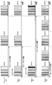
- FIG. 2 is a diagram showing an example of specifying an SS block in the case of a synchronous NW. This example shows the time resource of the SS block in a state where another cell is synchronized with the serving cell.
- the serving cell and other cells for example, neighboring cells of the serving cell
- # 0, # 1, and # 2 are synchronized, and the start of a predetermined SS burst set period is consistent between the cells.
- a plurality of SS bursts are transmitted within the SS burst set period, and one SS burst includes five SS blocks.
- the other cell # 0 has the same SS burst set period as that of the serving cell, and four SS blocks are included in one SS burst.
- the other cell # 1 has an SS burst set period longer (eg, twice) than the serving cell, and the other cell # 2 has an SS burst set period shorter (eg, half) than the serving cell. .
- a case will be described as an example where the UE detects an SS block in another cell # 0 under the situation of cell synchronization shown in FIG.
- the UE detects the first SS block by detecting the synchronization signal of the first SS block (SS # 1) among the four SS blocks included in the SS burst in the other cell # 0. If the PBCH included in the first SS block (SS # 1) is decoded, the time index of the SS block (SS # 1) can be found, but in this example, the PBCH is not decoded and the SS block (SS # 1) Timing information (corresponding to SS block time index) is specified.
- the UE determines which frame, slot, and / or symbol timing in the serving cell matches the detection timing of the first SS block (SS # 1). If it is determined which frame, slot and / or symbol timing in the serving cell matches the first SS block (SS # 1) in the other cell # 0, the first SS block (SS # 1) becomes the other cell #. It is possible to grasp which frame, slot and / or symbol timing corresponds to 0.
- the frame, slot and / or symbol timing in the other cell # 0 is determined for the first SS block (SS # 1) of the other cell # 0. Therefore, the UE can know the timing of the detected SS block in the other cell # 0 without reading the time index from the PBCH of the first SS block (SS # 1) of the other cell # 0. Frame and slot boundaries.
- the other cells # 1 and # 2 are cells having different SS burst set periods from the serving cell.
- the frame, slot and / or symbol timing in the other cells # 1 and # 2 can be specified for the detected SS block.
- the UE detects the second SS block (SS # 2) by detecting the synchronization signal of the second SS block (SS # 2) among the plurality of SS blocks included in the SS burst.
- the UE specifies which frame, slot and / or symbol timing in the serving cell corresponds to the detection timing of the target second SS block (SS # 2).
- the SS burst set period of the other cell # 1 is longer than that of the serving cell, but since the UE knows the frame, slot and / or symbol timing of the serving cell, the timing of the SS block detected in the other cell # 1 is similar to the above. Can be identified.
- the UE specifies which frame, slot and / or symbol timing in the other cell # 1 originally corresponds to the frame, slot and / or symbol timing corresponding to the detected SS block in the serving cell. Thus, it is determined which frame, slot, and / or symbol timing in the other cell # 1 corresponds to the second SS block (SS # 2) that is the measurement target in the other cell # 1.
- the UE When the UE performs RRM measurement using an SS block in another cell (for example, RSRP measurement), in addition to the RRM measurement result, the SS block timing information (timing information based on the serving cell) in the other cell and / or Alternatively, a measurement report including an SS block index (information derived based on the serving cell timing) may be transmitted to the network.
- the SS block timing information timing information based on the serving cell
- a measurement report including an SS block index information derived based on the serving cell timing
- the network can identify the SS block from the SS block timing information and / or index information included in the report, can determine which beam quality is good in the UE, and appropriately perform beam control (for example, handover). )it can.
- the UE can specify the SS block in the other cell without decoding the PBCH included in the SS block of the other cell.
- single beam operation is applied to another cell, SS blocks having the same SS block index are repeatedly transmitted in the SS burst set period in the other cell. Therefore, if an SS block synchronization signal is detected in another cell, it can be assumed that the detected SS block is an SS block having the same SS block index that is repeatedly transmitted in the other cell.
- the UE In a situation where single beam operation is applied to another cell, if the SS block is detected in the other cell, the UE is the only SS block in the other cell.
- the SS block can be specified. For example, it is handled that an SS block having a predetermined SS block index (for example, index # 0) is detected. Alternatively, it is not necessary to specify the SS block index for the detected SS block.
- information regarding the SS block used in a cell to which single beam operation is applied may be defined in the specification, or may be provided to the UE by higher layer signaling (for example, RRC signaling) or the like. You may be notified.
- higher layer signaling for example, RRC signaling
- the UE may transmit a measurement report including a predetermined SS block index (for example, index # 0) to the network in addition to the RRM measurement result. Good.
- a predetermined SS block index for example, index # 0
- the UE may not include the SS block index in the report. For example, the UE may send a report including the cell ID and the RRM measurement result to the network.
- the network receives the RRM measurement result of the SS block of the other cell from the UE in a situation where the other cell to be measured applies the single beam operation.
- the network knows the SS block index used in each cell, even if the report does not include the SS block index, it can recognize the SS block and shift to the subsequent processing.
- RRM requests are applied when the NR-PBCH included in the SS block of another cell is decoded and when the NR-PBCH is not decoded.
- RRM requirement Radio Resource Measurement requirement
- at least one of an SINR side condition, measurement time, accuracy, and number of measurement signals may be defined.
- a SINR lower limit value of a cell level to be detected may be defined.
- a maximum delay time with respect to a measurement delay may be defined.
- the number of measurement signals the number of cells of the measurement result reported to the network, the maximum number of cells, and the like may be defined.
- the UE determines whether to decode the NR-PBCH included in the SS block of another cell based on the predetermined information, when the UE decodes the NR-PBCH of the SS block, the UE A relaxed RRM request is applied compared to the case where PBCH is not decoded.
- the network may control the setting state (active state or inactive state) of the SCC based on the measurement result reported from the UE and the like.
- UE When UE decodes NR-PBCH included in SS block of other cell, at least one of request for measurement delay, side condition of SINR, and number of cells to be reported may be relaxed. For example, when decoding the NR-PBCH of the SS block of another cell, the UE may report a measurement result of a smaller number of cells than when not decoding the NR-PBCH.
- the UE when decoding the NR-PBCH of the SS block, the UE can apply a relaxed RRM request compared to the case of not decoding the NR-PBCH of the SS block. It is possible to suppress an increase in load on the UE when performing communication control based on the base station.
- the UE decodes the PBCH included in the SS block of another cell, reads the time index, and reports the time index to the network.
- the UE may report an index corresponding to the SS block time index to the network without reading the time index from the PBCH of the SS block.
- the UE when the UE detects the SS block of the other cell based on the synchronization signal of the SS block of the other cell, the UE determines the detection timing of the SS block without decoding the PBCH of the SS block. The time offset from the timing is detected. Further, the UE reports the detected time offset (which may be referred to as a time index) to the network as an index corresponding to the SS block time index.
- a time index which may be referred to as a time index
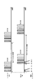
- FIG. 3 is a diagram illustrating a specific example of the SS block in the second embodiment.
- the index indicated by the time offset from the predetermined timing of the serving cell is reported as the detection timing of the SS block of the other cell.
- the serving cell and other cell # 0 are in an asynchronous state. The serving cell and other cell # 0 may be synchronized.
- a plurality of SS burst sets are arranged in the SS burst set cycle, and five SS blocks are transmitted in one SS burst set.
- the other cell # 0 is asynchronous with respect to the serving cell, and the number of SS blocks constituting one SS burst set is different from that of the serving cell.
- a time index (# 0,..., #N,%) Is defined with reference to a predetermined timing of the serving cell.
- the time index is determined based on the start timing of the SS burst set period in the serving cell. Specifically, in the other cell # 0, the first SS block of a certain SS burst set period corresponds to the time index #n. Note that the SS block in the second half of the SS burst set cycle in the other cell # 0 corresponds to the first half of the SS burst set cycle in the serving cell. For this reason, the time index also switches to the young number when it reaches the beginning of the SS burst set period in the serving cell.
- the UE receives the SS block in the SS burst set cycle in the other cell # 0 and detects the SS block based on the synchronization signal included in the SS block. For example, the UE measures RSRP in units of SS blocks, and reports RSRP measurement results to the network in units of SS blocks.
- the time index based on the predetermined timing of the serving cell is used instead of reading the time index from the PBCH of the SS block. For example, when the first SS block of the SS burst set period is detected in the other cell # 0, the time index #n based on the serving cell is reported.
- the time indexes related to the plurality of SS blocks may be reported to the network.
- the measurement results of the detected SS blocks are notified of individual measurement values without averaging.
- the third embodiment is an example in which the time index is not always read from the PBCH for the SS blocks of other cells regardless of the predetermined information.
- the third embodiment does not require an SS block index for identifying an individual SS block for a cell measurement result report in another cell.
- the UE When the UE does not decode the PBCH included in the SS block of the other cell, the UE performs control not including at least a part of the index for identifying the SS block of the other cell in the measurement report using the SS block of the other cell. Do.
- the UE may also include an SS block index for identifying the SS block of the serving cell in the measurement report using the SS block.
- the UE assumes that the serving cell requires the RSRP measurement result and SS block index in units of SS blocks, while the other cell does not require the RSRP measurement result and SS block index in units of SS blocks. Also good.
- the cell level RSRP related to the cell ID may be reported if the SS blocks are the same cell ID.
- the top N SS block level RSRPs among the RSRPs in units of SS blocks may be reported.
- the UE combines these two aspects, and reports one cell level RSRP together with the cell ID for one cell ID, and the top N SS block levels RSRP among the RSRPs in units of SS blocks without an SS block index. You may report.
- an SS block index that can be read from the PBCH of the SS block is not required, but information obtained in the process before decoding the PBCH of the SS block may be reported.
- the SS block index is implicitly expressed, it is assumed that some information for specifying the SS block is obtained in the process before decoding the PBCH of the SS block.
- a sequence time and / or frequency resource, scramble ID, etc.
- a signal PSS / SSS / PBCH
- a predetermined signal for example, a predetermined reference signal
- the SS burst index can be used together with the RS block level RSRP if the SS burst index is obtained without decoding the PBCH. You may report to
- the UE reports the SS block level measurement result for the serving cell by adding the SS block index, but does not report the SS block level measurement result for the other cells.
- the burden of decoding the PBCH of another cell in the UE can be reduced.
- wireless communication system Wireless communication system
- communication is performed using any one or a combination of the wireless communication methods according to the above embodiments of the present invention.
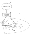
- FIG. 4 is a diagram illustrating an example of a schematic configuration of a wireless communication system according to an embodiment of the present invention.
- carrier aggregation (CA) and / or dual connectivity (DC) in which a plurality of basic frequency blocks (component carriers) each having a system bandwidth (for example, 20 MHz) of the LTE system as one unit are applied. can do.
- DC dual connectivity
- the wireless communication system 1 includes LTE (Long Term Evolution), LTE-A (LTE-Advanced), LTE-B (LTE-Beyond), SUPER 3G, IMT-Advanced 4G (4th generation mobile communication system), 5G. (5th generation mobile communication system), NR (New Radio), FRA (Future Radio Access), New-RAT (Radio Access Technology), etc., or a system that realizes these.
- the radio communication system 1 includes a radio base station 11 that forms a macro cell C1 having a relatively wide coverage, and a radio base station 12 (12a-12c) that is arranged in the macro cell C1 and forms a small cell C2 that is narrower than the macro cell C1. It is equipped with. Moreover, the user terminal 20 is arrange
- the user terminal 20 can be connected to both the radio base station 11 and the radio base station 12. It is assumed that the user terminal 20 uses the macro cell C1 and the small cell C2 at the same time using CA or DC. Moreover, the user terminal 20 may apply CA or DC using a plurality of cells (CC) (for example, 5 or less CCs, 6 or more CCs).
- CC cells
- Communication between the user terminal 20 and the radio base station 11 can be performed using a carrier having a relatively low frequency band (for example, 2 GHz) and a narrow bandwidth (also referred to as an existing carrier or a legacy carrier).
- a carrier having a relatively high frequency band for example, 3.5 GHz, 5 GHz, etc.
- the same carrier may be used.
- the configuration of the frequency band used by each radio base station is not limited to this.
- the user terminal 20 can perform communication using time division duplex (TDD) and / or frequency division duplex (FDD) in each cell.
- TDD time division duplex
- FDD frequency division duplex
- a single neurology may be applied, or a plurality of different neurology may be applied.
- the wireless base station 11 and the wireless base station 12 are connected by wire (for example, optical fiber compliant with CPRI (Common Public Radio Interface), X2 interface, etc.) or wirelessly. May be.
- the radio base station 11 and each radio base station 12 are connected to the higher station apparatus 30 and connected to the core network 40 via the higher station apparatus 30.
- the upper station device 30 includes, for example, an access gateway device, a radio network controller (RNC), a mobility management entity (MME), and the like, but is not limited thereto.
- RNC radio network controller
- MME mobility management entity
- Each radio base station 12 may be connected to the higher station apparatus 30 via the radio base station 11.
- the radio base station 11 is a radio base station having a relatively wide coverage, and may be called a macro base station, an aggregation node, an eNB (eNodeB), a transmission / reception point, or the like.
- the radio base station 12 is a radio base station having local coverage, and includes a small base station, a micro base station, a pico base station, a femto base station, a HeNB (Home eNodeB), an RRH (Remote Radio Head), and transmission / reception. It may be called a point.
- the radio base stations 11 and 12 are not distinguished, they are collectively referred to as a radio base station 10.
- Each user terminal 20 is a terminal that supports various communication schemes such as LTE and LTE-A, and may include not only a mobile communication terminal (mobile station) but also a fixed communication terminal (fixed station).
- orthogonal frequency division multiple access (OFDMA) is applied to the downlink, and single carrier-frequency division multiple access (SC-FDMA) is used for the uplink.
- SC-FDMA single carrier-frequency division multiple access
- Frequency Division Multiple Access and / or OFDMA is applied.
- OFDMA is a multi-carrier transmission scheme that performs communication by dividing a frequency band into a plurality of narrow frequency bands (subcarriers) and mapping data to each subcarrier.
- SC-FDMA is a single carrier transmission in which the system bandwidth is divided into bands each composed of one or continuous resource blocks for each terminal, and a plurality of terminals use different bands to reduce interference between terminals. It is a method.
- the uplink and downlink radio access schemes are not limited to these combinations, and other radio access schemes may be used.
- downlink channels include a downlink shared channel (PDSCH) shared by each user terminal 20, a broadcast channel (PBCH: Physical Broadcast Channel), a downlink L1 / L2 control channel, and the like. Used. User data, higher layer control information, SIB (System Information Block), etc. are transmitted by PDSCH. Moreover, MIB (Master Information Block) is transmitted by PBCH.
- PDSCH downlink shared channel
- PBCH Physical Broadcast Channel
- SIB System Information Block
- MIB Master Information Block
- Downlink L1 / L2 control channels include PDCCH (Physical Downlink Control Channel), EPDCCH (Enhanced Physical Downlink Control Channel), PCFICH (Physical Control Format Indicator Channel), PHICH (Physical Hybrid-ARQ Indicator Channel), and the like.
- Downlink control information (DCI: Downlink Control Information) including PDSCH and / or PUSCH scheduling information is transmitted by the PDCCH.
- scheduling information may be notified by DCI.
- DCI for scheduling DL data reception may be referred to as DL assignment
- DCI for scheduling UL data transmission may be referred to as UL grant.
- the number of OFDM symbols used for PDCCH is transmitted by PCFICH.
- the PHICH transmits HARQ (Hybrid Automatic Repeat reQuest) delivery confirmation information (for example, retransmission control information, HARQ-ACK, ACK / NACK, etc.) to the PUSCH.
- HARQ Hybrid Automatic Repeat reQuest
- EPDCCH is frequency-division multiplexed with PDSCH (downlink shared data channel), and is used for transmission of DCI and the like in the same manner as PDCCH.
- an uplink shared channel (PUSCH) shared by each user terminal 20
- an uplink control channel (PUCCH: Physical Uplink Control Channel)
- a random access channel (PRACH: Physical Random Access Channel)
- User data, higher layer control information, etc. are transmitted by PUSCH.
- downlink radio quality information CQI: Channel Quality Indicator
- delivery confirmation information SR
- scheduling request etc.
- a random access preamble for establishing connection with the cell is transmitted by the PRACH.
- a cell-specific reference signal CRS
- CSI-RS channel state information reference signal
- DMRS demodulation reference signal
- PRS Positioning Reference Signal
- a measurement reference signal SRS: Sounding Reference Signal
- a demodulation reference signal DMRS
- the DMRS may be referred to as a user terminal specific reference signal (UE-specific Reference Signal). Further, the transmitted reference signal is not limited to these.
- FIG. 5 is a diagram illustrating an example of the overall configuration of a radio base station according to an embodiment of the present invention.
- the radio base station 10 includes a plurality of transmission / reception antennas 101, an amplifier unit 102, a transmission / reception unit 103, a baseband signal processing unit 104, a call processing unit 105, and a transmission path interface 106.
- the transmission / reception antenna 101, the amplifier unit 102, and the transmission / reception unit 103 may each be configured to include one or more.
- User data transmitted from the radio base station 10 to the user terminal 20 via the downlink is input from the higher station apparatus 30 to the baseband signal processing unit 104 via the transmission path interface 106.
- PDCP Packet Data Convergence Protocol
- RLC Radio Link Control
- MAC Medium Access
- Retransmission control for example, HARQ transmission processing
- scheduling transmission format selection, channel coding, Inverse Fast Fourier Transform (IFFT) processing, precoding processing, and other transmission processing
- IFFT Inverse Fast Fourier Transform
- precoding processing precoding processing, and other transmission processing
- the downlink control signal is also subjected to transmission processing such as channel coding and inverse fast Fourier transform, and is transferred to the transmission / reception unit 103.
- the transmission / reception unit 103 converts the baseband signal output by precoding for each antenna from the baseband signal processing unit 104 to a radio frequency band and transmits the converted signal.
- the radio frequency signal frequency-converted by the transmission / reception unit 103 is amplified by the amplifier unit 102 and transmitted from the transmission / reception antenna 101.
- the transmission / reception unit 103 can be configured by a transmitter / receiver, a transmission / reception circuit, or a transmission / reception device, which is described based on common recognition in the technical field according to the present invention.
- the transmission / reception part 103 may be comprised as an integral transmission / reception part, and may be comprised from a transmission part and a receiving part.
- the radio frequency signal received by the transmission / reception antenna 101 is amplified by the amplifier unit 102.
- the transmission / reception unit 103 receives the uplink signal amplified by the amplifier unit 102.
- the transmission / reception unit 103 converts the frequency of the received signal into a baseband signal and outputs it to the baseband signal processing unit 104.
- the baseband signal processing unit 104 performs fast Fourier transform (FFT) processing, inverse discrete Fourier transform (IDFT: Inverse Discrete Fourier Transform) processing, and error correction on user data included in the input upstream signal.
- FFT fast Fourier transform
- IDFT inverse discrete Fourier transform
- Decoding, MAC retransmission control reception processing, RLC layer and PDCP layer reception processing are performed and transferred to the upper station apparatus 30 via the transmission path interface 106.
- the call processor 105 performs communication channel call processing (setting, release, etc.), status management of the radio base station 10, radio resource management, and the like.
- the transmission path interface 106 transmits and receives signals to and from the higher station apparatus 30 via a predetermined interface.
- the transmission path interface 106 transmits / receives signals (backhaul signaling) to / from other radio base stations 10 via an interface between base stations (for example, an optical fiber compliant with CPRI (Common Public Radio Interface), X2 interface). May be.
- CPRI Common Public Radio Interface
- X2 interface May be.
- the transmission / reception unit 103 may further include an analog beam forming unit that performs analog beam forming.
- the analog beam forming unit includes an analog beam forming circuit (for example, phase shifter, phase shift circuit) or an analog beam forming apparatus (for example, phase shifter) described based on common recognition in the technical field according to the present invention. May be.
- the transmission / reception antenna 101 may be constituted by, for example, an array antenna.
- the transmission / reception unit 103 may transmit a signal using a transmission beam or may receive a signal using a reception beam.
- the transmission / reception unit 103 may transmit and / or receive a signal using a predetermined beam determined by the control unit 301.
- the transmission / reception unit 103 transmits one or more synchronization signal blocks (SS blocks) including a synchronization signal (for example, NR-PSS, NR-SSS, etc.) and a broadcast channel (for example, NR-PBCH).
- SS blocks synchronization signal blocks
- the transceiver 103 may transmit NR-PBCH having the same content and / or configuration using a plurality of different SS blocks.
- the transmission / reception unit 103 indicates whether to decode the PBCH included in the SS block of another cell, information on whether the other cell to be measured is synchronized with the serving cell, and whether the other cell to be measured is a single beam operation. Information regarding whether or not the information is applied may be transmitted to the user terminal 20.
- the transmission / reception unit 103 may receive a measurement report at the cell level and / or the SS block level from the user terminal 20.
- FIG. 6 is a diagram illustrating an example of a functional configuration of the radio base station according to the embodiment of the present invention.
- the functional block of the characteristic part in this embodiment is mainly shown, and it may be assumed that the wireless base station 10 also has other functional blocks necessary for wireless communication.
- the baseband signal processing unit 104 includes at least a control unit (scheduler) 301, a transmission signal generation unit 302, a mapping unit 303, a reception signal processing unit 304, and a measurement unit 305. These configurations may be included in the radio base station 10, and a part or all of the configurations may not be included in the baseband signal processing unit 104.
- the control unit (scheduler) 301 controls the entire radio base station 10.
- the control part 301 can be comprised from the controller, the control circuit, or control apparatus demonstrated based on the common recognition in the technical field which concerns on this invention.
- the control unit 301 controls, for example, signal generation in the transmission signal generation unit 302, signal allocation in the mapping unit 303, and the like.
- the control unit 301 also controls signal reception processing in the reception signal processing unit 304, signal measurement in the measurement unit 305, and the like.
- the control unit 301 schedules system information, downlink data signals (for example, signals transmitted by PDSCH), downlink control signals (for example, signals transmitted by PDCCH and / or EPDCCH, delivery confirmation information, etc.) (for example, resource Control).
- the control unit 301 controls generation of a downlink control signal, a downlink data signal, and the like based on a result of determining whether or not retransmission control is necessary for the uplink data signal.
- the control unit 301 controls scheduling of synchronization signals (for example, PSS (Primary Synchronization Signal) / SSS (Secondary Synchronization Signal)), downlink reference signals (for example, CRS, CSI-RS, DMRS) and the like.
- control unit 301 includes an uplink data signal (for example, a signal transmitted on PUSCH), an uplink control signal (for example, a signal transmitted on PUCCH and / or PUSCH, delivery confirmation information, etc.), a random access preamble (for example, Scheduling of the uplink reference signal and the like.
- uplink data signal for example, a signal transmitted on PUSCH
- uplink control signal for example, a signal transmitted on PUCCH and / or PUSCH, delivery confirmation information, etc.
- a random access preamble for example, Scheduling of the uplink reference signal and the like.
- the control unit 301 uses the digital BF (for example, precoding) in the baseband signal processing unit 104 and / or the analog BF (for example, phase rotation) in the transmission / reception unit 103 to form a transmission beam and / or a reception beam. May be performed.
- the control unit 301 may perform control to form a beam based on downlink propagation path information, uplink propagation path information, and the like. Such propagation path information may be acquired from the reception signal processing unit 304 and / or the measurement unit 305.
- the control unit 301 may explicitly indicate that the user terminal 20 does not decode the PBCH included in the SS block of another cell using RRC signaling or SIB.
- control unit 301 sets SS blocks so that a predetermined SS burst set (see FIG. 1) is realized for the serving cell and other cells.
- a synchronization signal and PBCH are scheduled for each SS block.
- the transmission / reception timing of each cell may be controlled so that the serving cell and other cells # 0, # 1, and # 2 are synchronized.
- control unit 301 may receive a report of measurement results (for example, cell level measurement result, SS block level measurement result) in the serving cell and other cells from the user terminal 20.
- a report of measurement results for example, cell level measurement result, SS block level measurement result
- the control unit 301 and the RSRP measurement result in the other cell to be measured and the SS block timing information in the other cell (timing based on the serving cell) Information are specified.
- the control unit 301 may determine which beam quality is good in the user terminal 20 based on the received measurement result, and may perform control to change the beam.
- control unit 301 may receive the RSRP measurement result of the SS block in the other cell from the user terminal 20 in a situation where the other cell to be measured applies the single beam operation. In this case, the control unit 301 can identify the SS block because it is known that the other cell is a single beam even if the report has no SS block index.
- control unit 301 may assume different RRM requests regarding measurement in other cells depending on whether the user terminal 20 decodes the PBCH included in the SS block of the other cell or not decodes the PBCH. For example, when the PBCH included in the SS block of another cell is decoded in the user terminal 20, the control unit 301 relaxes at least one of the incident condition (side condition) of SINR, measurement time, accuracy, and the number of measurement signals. You may assume that
- the control unit 301 detects the user terminal 20 in the other cell based on the time index.
- An SS block may be specified.
- control unit 301 specifies the SS block detected by the user terminal 20 in another cell from the information. Also good.
- the transmission signal generation unit 302 generates a downlink signal (downlink control signal, downlink data signal, downlink reference signal, etc.) based on an instruction from the control unit 301, and outputs it to the mapping unit 303.
- the transmission signal generation unit 302 can be configured by a signal generator, a signal generation circuit, or a signal generation device described based on common recognition in the technical field according to the present invention.
- the transmission signal generation unit 302 generates, for example, a DL assignment for notifying downlink data allocation information and / or a UL grant for notifying uplink data allocation information based on an instruction from the control unit 301.
- the DL assignment and UL grant are both DCI and follow the corresponding DCI format.
- the downlink data signal is subjected to coding processing and modulation processing according to a coding rate, a modulation scheme, and the like determined based on channel state information (CSI: Channel State Information) from each user terminal 20.
- CSI Channel State Information
- the mapping unit 303 maps the downlink signal generated by the transmission signal generation unit 302 to a predetermined radio resource based on an instruction from the control unit 301, and outputs it to the transmission / reception unit 103.
- the mapping unit 303 can be configured by a mapper, a mapping circuit, or a mapping device described based on common recognition in the technical field according to the present invention.
- the reception signal processing unit 304 performs reception processing (for example, demapping, demodulation, decoding, etc.) on the reception signal input from the transmission / reception unit 103.
- the received signal is, for example, an uplink signal (uplink control signal, uplink data signal, uplink reference signal, etc.) transmitted from the user terminal 20.
- the reception signal processing unit 304 can be configured by a signal processor, a signal processing circuit, or a signal processing device described based on common recognition in the technical field according to the present invention.
- the reception signal processing unit 304 outputs the information decoded by the reception processing to the control unit 301. For example, when receiving PUCCH including HARQ-ACK, HARQ-ACK is output to control section 301.
- the reception signal processing unit 304 outputs the reception signal and / or the signal after reception processing to the measurement unit 305.
- the measurement unit 305 performs measurement on the received signal.
- the measurement part 305 can be comprised from the measuring device, measurement circuit, or measurement apparatus demonstrated based on common recognition in the technical field which concerns on this invention.
- the measurement unit 305 may perform RRM (Radio Resource Management) measurement, CSI (Channel State Information) measurement, and the like based on the received signal.
- the measurement unit 305 includes received power (for example, RSRP (Reference Signal Received Power)), received quality (for example, RSRQ (Reference Signal Received Quality), SINR (Signal to Interference plus Noise Ratio), SNR (Signal to Noise Ratio)).
- Signal strength for example, RSSI (Received Signal Strength Indicator)
- propagation path information for example, CSI
- the measurement result may be output to the control unit 301.
- FIG. 7 is a diagram illustrating an example of an overall configuration of a user terminal according to an embodiment of the present invention.
- the user terminal 20 includes a plurality of transmission / reception antennas 201, an amplifier unit 202, a transmission / reception unit 203, a baseband signal processing unit 204, and an application unit 205.
- the transmission / reception antenna 201, the amplifier unit 202, and the transmission / reception unit 203 may each be configured to include one or more.
- the radio frequency signal received by the transmission / reception antenna 201 is amplified by the amplifier unit 202.
- the transmission / reception unit 203 receives the downlink signal amplified by the amplifier unit 202.
- the transmission / reception unit 203 converts the frequency of the received signal into a baseband signal and outputs it to the baseband signal processing unit 204.
- the transmission / reception unit 203 can be configured by a transmitter / receiver, a transmission / reception circuit, or a transmission / reception device described based on common recognition in the technical field according to the present invention.
- the transmission / reception unit 203 may be configured as an integral transmission / reception unit, or may be configured from a transmission unit and a reception unit.
- the baseband signal processing unit 204 performs FFT processing, error correction decoding, retransmission control reception processing, and the like on the input baseband signal.
- the downlink user data is transferred to the application unit 205.
- the application unit 205 performs processing related to layers higher than the physical layer and the MAC layer. Also, broadcast information of downlink data may be transferred to the application unit 205.
- uplink user data is input from the application unit 205 to the baseband signal processing unit 204.
- the baseband signal processing unit 204 performs transmission / reception units for retransmission control (for example, HARQ transmission processing), channel coding, precoding, discrete Fourier transform (DFT) processing, IFFT processing, and the like.
- the transmission / reception unit 203 converts the baseband signal output from the baseband signal processing unit 204 into a radio frequency band and transmits it.
- the radio frequency signal frequency-converted by the transmission / reception unit 203 is amplified by the amplifier unit 202 and transmitted from the transmission / reception antenna 201.
- the transmission / reception unit 203 may further include an analog beam forming unit that performs analog beam forming.
- the analog beam forming unit includes an analog beam forming circuit (for example, phase shifter, phase shift circuit) or an analog beam forming apparatus (for example, phase shifter) described based on common recognition in the technical field according to the present invention. May be.
- the transmission / reception antenna 201 may be constituted by, for example, an array antenna.
- the transmission / reception unit 203 may transmit a signal using a transmission beam, or may receive a signal using a reception beam.
- the transmission / reception unit 203 may transmit and / or receive a signal using a predetermined beam determined by the control unit 401.
- the transmission / reception unit 203 receives one or more synchronization signal blocks (SS blocks) including a synchronization signal (for example, NR-PSS, NR-SSS, etc.) and a broadcast channel (for example, NR-PBCH).
- SS blocks including a synchronization signal (for example, NR-PSS, NR-SSS, etc.) and a broadcast channel (for example, NR-PBCH).
- a synchronization signal for example, NR-PSS, NR-SSS, etc.
- a broadcast channel for example, NR-PBCH
- the transmission / reception unit 203 indicates whether or not to decode the PBCH included in the SS block of the other cell, information on whether or not the other cell to be measured is synchronized with the serving cell, Information regarding whether or not the information is applied may be received from the radio base station 10.
- the transmission / reception unit 203 may transmit a cell level and / or SS block level measurement report to the radio base station 10.
- FIG. 8 is a diagram illustrating an example of a functional configuration of a user terminal according to an embodiment of the present invention.
- the functional block of the characteristic part in this embodiment is mainly shown, and it may be assumed that the user terminal 20 also has other functional blocks necessary for wireless communication.
- the baseband signal processing unit 204 included in the user terminal 20 includes at least a control unit 401, a transmission signal generation unit 402, a mapping unit 403, a reception signal processing unit 404, and a measurement unit 405. Note that these configurations may be included in the user terminal 20, and some or all of the configurations may not be included in the baseband signal processing unit 204.
- the control unit 401 controls the entire user terminal 20.
- the control unit 401 can be composed of a controller, a control circuit, or a control device described based on common recognition in the technical field according to the present invention.
- the control unit 401 controls, for example, signal generation in the transmission signal generation unit 402, signal allocation in the mapping unit 403, and the like.
- the control unit 401 also controls signal reception processing in the reception signal processing unit 404, signal measurement in the measurement unit 405, and the like.
- the control unit 401 acquires the downlink control signal and the downlink data signal transmitted from the radio base station 10 from the reception signal processing unit 404.
- the control unit 401 controls the generation of the uplink control signal and / or the uplink data signal based on the result of determining the necessity of retransmission control for the downlink control signal and / or the downlink data signal.
- the control unit 401 uses the digital BF (for example, precoding) in the baseband signal processing unit 204 and / or the analog BF (for example, phase rotation) in the transmission / reception unit 203 to form a transmission beam and / or a reception beam. May be performed.
- the control unit 401 may perform control to form a beam based on downlink propagation path information, uplink propagation path information, and the like. Such propagation path information may be acquired from the reception signal processing unit 404 and / or the measurement unit 405.
- control unit 401 receives one or more SS blocks including a synchronization signal and a broadcast channel (PBCH) from the serving cell and other cells, and decodes the PBCH included in the SS blocks of the other cells based on predetermined information. Judge whether or not.
- PBCH broadcast channel
- the predetermined information may be an instruction as to whether or not to decode the PBCH included in the SS block of another cell.
- the control unit 401 can use information regarding whether or not another cell to be measured is synchronized with the serving cell as the predetermined information. Moreover, the control part 401 can use the information regarding whether the other cell of a measurement object is applying single beam operation as predetermined information.
- control part 401 may specify the detection timing of the SS block in another cell based on the predetermined timing of a serving cell, when not decoding PBCH contained in the SS block of another cell.
- control unit 401 when the control unit 401 does not decode the PBCH included in the SS block of another cell, at least a part of the index for specifying the SS block of the other cell in the measurement report using the SS block of the other cell. You may perform control which does not include.
- the control unit 401 includes an index for specifying the SS block of the serving cell in the measurement report using the SS block related to the serving cell, and specifies the SS block of the other cell in the measurement report using the SS block related to the other cell. You may perform control which does not include the index of.
- the control unit 401 determines whether to decode the PBCH included in the SS block of the other cell. For cell measurement (including SS block level measurement), an RRM request different from the case where the PBCH included in the SS block is not decoded may be applied. For example, when the PBCH included in the SS block of another cell is decoded, the relaxed RRM request is applied as compared with the case where the PBCH is not decoded with respect to the measurement of the other cell.
- control unit 401 may update parameters used for control based on the information.
- the transmission signal generation unit 402 generates an uplink signal (uplink control signal, uplink data signal, uplink reference signal, etc.) based on an instruction from the control unit 401 and outputs the uplink signal to the mapping unit 403.
- the transmission signal generation unit 402 can be configured by a signal generator, a signal generation circuit, or a signal generation device described based on common recognition in the technical field according to the present invention.
- the transmission signal generation unit 402 generates an uplink control signal related to delivery confirmation information, channel state information (CSI), and the like based on an instruction from the control unit 401, for example. In addition, the transmission signal generation unit 402 generates an uplink data signal based on an instruction from the control unit 401. For example, the transmission signal generation unit 402 is instructed by the control unit 401 to generate an uplink data signal when the UL grant is included in the downlink control signal notified from the radio base station 10.
- CSI channel state information
- the mapping unit 403 maps the uplink signal generated by the transmission signal generation unit 402 to a radio resource based on an instruction from the control unit 401, and outputs the radio signal to the transmission / reception unit 203.
- the mapping unit 403 can be configured by a mapper, a mapping circuit, or a mapping device described based on common recognition in the technical field according to the present invention.
- the reception signal processing unit 404 performs reception processing (for example, demapping, demodulation, decoding, etc.) on the reception signal input from the transmission / reception unit 203.
- the received signal is, for example, a downlink signal (downlink control signal, downlink data signal, downlink reference signal, etc.) transmitted from the radio base station 10.
- the reception signal processing unit 404 can be configured by a signal processor, a signal processing circuit, or a signal processing device described based on common recognition in the technical field according to the present invention. Further, the reception signal processing unit 404 can constitute a reception unit according to the present invention.
- the reception signal processing unit 404 outputs the information decoded by the reception processing to the control unit 401.
- the reception signal processing unit 404 outputs, for example, broadcast information, system information, RRC signaling, DCI, and the like to the control unit 401.
- the reception signal processing unit 404 outputs the reception signal and / or the signal after reception processing to the measurement unit 405.
- the measurement unit 405 performs measurement on the received signal.
- the measurement part 405 can be comprised from the measuring device, measurement circuit, or measurement apparatus demonstrated based on common recognition in the technical field which concerns on this invention.
- the measurement unit 405 may perform RRM measurement, CSI measurement, and the like based on the received signal.
- the measurement unit 405 may measure reception power (for example, RSRP), reception quality (for example, RSRQ, SINR, SNR), signal strength (for example, RSSI), propagation path information (for example, CSI), and the like.
- the measurement result may be output to the control unit 401.
- each functional block (components) are realized by any combination of hardware and / or software.
- the method for realizing each functional block is not particularly limited. That is, each functional block may be realized using one device physically and / or logically coupled, or directly and / or two or more devices physically and / or logically separated. Alternatively, it may be realized indirectly by connecting (for example, using wired and / or wireless) and using these plural devices.
- a radio base station, a user terminal, etc. in an embodiment of the present invention may function as a computer that performs processing of the radio communication method of the present invention.
- FIG. 9 is a diagram illustrating an example of a hardware configuration of a radio base station and a user terminal according to an embodiment of the present invention.
- the wireless base station 10 and the user terminal 20 described above may be physically configured as a computer device including a processor 1001, a memory 1002, a storage 1003, a communication device 1004, an input device 1005, an output device 1006, a bus 1007, and the like. Good.
- the term “apparatus” can be read as a circuit, a device, a unit, or the like.
- the hardware configurations of the radio base station 10 and the user terminal 20 may be configured to include one or a plurality of each device illustrated in the figure, or may be configured not to include some devices.
- processor 1001 may be implemented by one or more chips.
- Each function in the radio base station 10 and the user terminal 20 is calculated by causing the processor 1001 to perform calculations by reading predetermined software (programs) on hardware such as the processor 1001 and the memory 1002, for example, via the communication device 1004. This is realized by controlling communication and controlling reading and / or writing of data in the memory 1002 and the storage 1003.
- the processor 1001 controls the entire computer by operating an operating system, for example.
- the processor 1001 may be configured by a central processing unit (CPU) including an interface with peripheral devices, a control device, an arithmetic device, a register, and the like.
- CPU central processing unit
- the baseband signal processing unit 104 (204) and the call processing unit 105 described above may be realized by the processor 1001.
- the processor 1001 reads programs (program codes), software modules, data, and the like from the storage 1003 and / or the communication device 1004 to the memory 1002, and executes various processes according to these.
- programs program codes
- software modules software modules
- data data
- the control unit 401 of the user terminal 20 may be realized by a control program stored in the memory 1002 and operating in the processor 1001, and may be realized similarly for other functional blocks.
- the memory 1002 is a computer-readable recording medium such as a ROM (Read Only Memory), an EPROM (Erasable Programmable ROM), an EEPROM (Electrically EPROM), a RAM (Random Access Memory), or any other suitable storage medium. It may be configured by one.
- the memory 1002 may be called a register, a cache, a main memory (main storage device), or the like.
- the memory 1002 can store programs (program codes), software modules, and the like that can be executed to implement the wireless communication method according to an embodiment of the present invention.
- the storage 1003 is a computer-readable recording medium such as a flexible disk, a floppy (registered trademark) disk, a magneto-optical disk (for example, a compact disk (CD-ROM (Compact Disc ROM)), a digital versatile disk, Blu-ray® disk), removable disk, hard disk drive, smart card, flash memory device (eg, card, stick, key drive), magnetic stripe, database, server, or other suitable storage medium It may be constituted by.
- the storage 1003 may be referred to as an auxiliary storage device.
- the communication device 1004 is hardware (transmission / reception device) for performing communication between computers via a wired and / or wireless network, and is also referred to as a network device, a network controller, a network card, a communication module, or the like.
- the communication device 1004 includes, for example, a high-frequency switch, a duplexer, a filter, a frequency synthesizer, etc., in order to realize frequency division duplex (FDD) and / or time division duplex (TDD). It may be configured.
- FDD frequency division duplex
- TDD time division duplex
- the transmission / reception antenna 101 (201), the amplifier unit 102 (202), the transmission / reception unit 103 (203), the transmission path interface 106, and the like described above may be realized by the communication device 1004.
- the input device 1005 is an input device (for example, a keyboard, a mouse, a microphone, a switch, a button, a sensor, etc.) that accepts an input from the outside.
- the output device 1006 is an output device (for example, a display, a speaker, an LED (Light Emitting Diode) lamp, etc.) that performs output to the outside.
- the input device 1005 and the output device 1006 may have an integrated configuration (for example, a touch panel).
- the devices such as the processor 1001 and the memory 1002 are connected by a bus 1007 for communicating information.
- the bus 1007 may be configured using a single bus, or may be configured using a different bus for each device.
- the radio base station 10 and the user terminal 20 include a microprocessor, a digital signal processor (DSP), an ASIC (Application Specific Integrated Circuit), a PLD (Programmable Logic Device), an FPGA (Field Programmable Gate Array), and the like. It may be configured including hardware, and a part or all of each functional block may be realized using the hardware. For example, the processor 1001 may be implemented using at least one of these hardware.
- DSP digital signal processor
- ASIC Application Specific Integrated Circuit
- PLD Programmable Logic Device
- FPGA Field Programmable Gate Array
- the channel and / or symbol may be a signal (signaling).
- the signal may be a message.
- the reference signal may be abbreviated as RS (Reference Signal), and may be referred to as a pilot, a pilot signal, or the like depending on an applied standard.
- a component carrier CC: Component Carrier
- CC Component Carrier
- the radio frame may be configured by one or a plurality of periods (frames) in the time domain.
- Each of the one or more periods (frames) constituting the radio frame may be referred to as a subframe.
- a subframe may be composed of one or more slots in the time domain.
- the subframe may have a fixed time length (eg, 1 ms) that does not depend on the neurology.
- the slot may be configured by one or a plurality of symbols (OFDM (Orthogonal Frequency Division Multiplexing) symbol, SC-FDMA (Single Carrier Frequency Division Multiple Access) symbol, etc.) in the time domain.
- the slot may be a time unit based on the numerology.
- the slot may include a plurality of mini slots. Each minislot may be configured with one or more symbols in the time domain. The minislot may also be called a subslot.
- Radio frame, subframe, slot, minislot, and symbol all represent time units when transmitting signals. Different names may be used for the radio frame, subframe, slot, minislot, and symbol.
- one subframe may be called a transmission time interval (TTI)
- TTI transmission time interval
- a plurality of consecutive subframes may be called a TTI
- TTI slot or one minislot
- a unit representing TTI may be called a slot, a minislot, or the like instead of a subframe.
- TTI means, for example, a minimum time unit for scheduling in wireless communication.
- a radio base station performs scheduling for assigning radio resources (frequency bandwidth, transmission power, etc. that can be used in each user terminal) to each user terminal in units of TTI.
- the definition of TTI is not limited to this.
- the TTI may be a transmission time unit of a channel-encoded data packet (transport block), a code block, and / or a code word, or may be a processing unit such as scheduling or link adaptation.
- a time interval for example, the number of symbols
- a transport block, a code block, and / or a code word is actually mapped may be shorter than the TTI.
- one or more TTIs may be the minimum scheduling unit. Further, the number of slots (the number of mini-slots) constituting the minimum time unit of the scheduling may be controlled.
- a TTI having a time length of 1 ms may be called a normal TTI (TTI in LTE Rel. 8-12), a normal TTI, a long TTI, a normal subframe, a normal subframe, or a long subframe.
- a TTI shorter than a normal TTI may be called a shortened TTI, a short TTI, a partial TTI (partial or fractional TTI), a shortened subframe, a short subframe, a minislot, or a subslot.
- a long TTI (eg, normal TTI, subframe, etc.) may be read as a TTI having a time length exceeding 1 ms, and a short TTI (eg, shortened TTI) is less than the TTI length of the long TTI and 1 ms. It may be replaced with a TTI having the above TTI length.
- a resource block is a resource allocation unit in the time domain and the frequency domain, and may include one or a plurality of continuous subcarriers (subcarriers) in the frequency domain. Further, the RB may include one or a plurality of symbols in the time domain, and may have a length of 1 slot, 1 mini slot, 1 subframe, or 1 TTI. One TTI and one subframe may each be composed of one or a plurality of resource blocks.
- One or more RBs include physical resource blocks (PRB), sub-carrier groups (SCG), resource element groups (REG), PRB pairs, RB pairs, etc. May be called.
- the resource block may be configured by one or a plurality of resource elements (RE: Resource Element).
- RE Resource Element
- 1RE may be a radio resource region of 1 subcarrier and 1 symbol.
- the structure of the above-described radio frame, subframe, slot, minislot, symbol, etc. is merely an example.
- the number of subframes included in a radio frame, the number of slots per subframe or radio frame, the number of minislots included in the slot, the number of symbols and RBs included in the slot or minislot, and the RB The number of subcarriers, the number of symbols in the TTI, the symbol length, the cyclic prefix (CP) length, and the like can be variously changed.
- the information, parameters, and the like described in this specification may be expressed using absolute values, may be expressed using relative values from a predetermined value, or other corresponding information may be used. May be represented.
- the radio resource may be indicated by a predetermined index.
- names used for parameters and the like are not limited names in any way.
- various channels PUCCH (Physical Uplink Control Channel), PDCCH (Physical Downlink Control Channel), etc.
- information elements can be identified by any suitable name, so the various channels and information elements assigned to them.
- the name is not limited in any way.
- information, signals, etc. can be output from the upper layer to the lower layer and / or from the lower layer to the upper layer.
- Information, signals, and the like may be input / output via a plurality of network nodes.
- the input / output information, signals, etc. may be stored in a specific location (for example, a memory) or may be managed using a management table. Input / output information, signals, and the like can be overwritten, updated, or added. The output information, signals, etc. may be deleted. Input information, signals, and the like may be transmitted to other devices.
- information notification includes physical layer signaling (eg, downlink control information (DCI), uplink control information (UCI)), upper layer signaling (eg, RRC (Radio Resource Control) signaling), It may be implemented by broadcast information (Master Information Block (MIB), System Information Block (SIB), etc.), MAC (Medium Access Control) signaling), other signals, or a combination thereof.
- DCI downlink control information
- UCI uplink control information
- RRC Radio Resource Control
- MIB Master Information Block
- SIB System Information Block
- MAC Medium Access Control
- the physical layer signaling may be referred to as L1 / L2 (Layer 1 / Layer 2) control information (L1 / L2 control signal), L1 control information (L1 control signal), or the like.
- the RRC signaling may be referred to as an RRC message, and may be, for example, an RRC connection setup (RRCConnectionSetup) message, an RRC connection reconfiguration (RRCConnectionReconfiguration) message, or the like.
- the MAC signaling may be notified using, for example, a MAC control element (MAC CE (Control Element)).
- notification of predetermined information is not limited to explicit notification, but implicitly (for example, by not performing notification of the predetermined information or other information) May be performed).
- the determination may be performed by a value represented by 1 bit (0 or 1), or may be performed by a boolean value represented by true or false.
- the comparison may be performed by numerical comparison (for example, comparison with a predetermined value).
- software, instructions, information, etc. may be sent and received via a transmission medium.
- software can use websites, servers using wired technology (coaxial cable, fiber optic cable, twisted pair, digital subscriber line (DSL), etc.) and / or wireless technology (infrared, microwave, etc.) , Or other remote sources, these wired and / or wireless technologies are included within the definition of transmission media.
- system and “network” used in this specification are used interchangeably.
- base station BS
- radio base station eNB
- gNB gNodeB
- cell gNodeB
- cell group a base station
- carrier a base station
- a base station may also be called in terms such as a fixed station, NodeB, eNodeB (eNB), access point, transmission point, reception point, femtocell, and small cell.
- the base station can accommodate one or a plurality of (for example, three) cells (also called sectors). If the base station accommodates multiple cells, the entire coverage area of the base station can be partitioned into multiple smaller areas, each smaller area being a base station subsystem (eg, an indoor small base station (RRH: The term “cell” or “sector” refers to part or all of the coverage area of a base station and / or base station subsystem that provides communication service in this coverage. Point to.
- RRH indoor small base station
- MS mobile station
- UE user equipment
- terminal may be used interchangeably.
- a base station may also be called in terms such as a fixed station, NodeB, eNodeB (eNB), access point, transmission point, reception point, femtocell, and small cell.
- NodeB NodeB
- eNodeB eNodeB
- access point transmission point
- reception point femtocell
- small cell small cell
- a mobile station is defined by those skilled in the art as a subscriber station, mobile unit, subscriber unit, wireless unit, remote unit, mobile device, wireless device, wireless communication device, remote device, mobile subscriber station, access terminal, mobile terminal, wireless It may also be called terminal, remote terminal, handset, user agent, mobile client, client or some other suitable terminology.
- the radio base station in this specification may be read by the user terminal.
- each aspect / embodiment of the present invention may be applied to a configuration in which communication between a radio base station and a user terminal is replaced with communication between a plurality of user terminals (D2D: Device-to-Device).
- the user terminal 20 may have a function that the wireless base station 10 has.
- words such as “up” and “down” may be read as “side”.
- the uplink channel may be read as a side channel.
- a user terminal in this specification may be read by a radio base station.
- the wireless base station 10 may have a function that the user terminal 20 has.
- the operation performed by the base station may be performed by the upper node in some cases.
- various operations performed for communication with a terminal may include a base station and one or more network nodes other than the base station (for example, It is obvious that this can be done by MME (Mobility Management Entity), S-GW (Serving-Gateway), etc., but not limited thereto) or a combination thereof.
- MME Mobility Management Entity
- S-GW Serving-Gateway
- each aspect / embodiment described in this specification may be used alone, may be used in combination, or may be switched according to execution.
- the order of the processing procedures, sequences, flowcharts, and the like of each aspect / embodiment described in this specification may be changed as long as there is no contradiction.
- the methods described herein present the elements of the various steps in an exemplary order and are not limited to the specific order presented.
- Each aspect / embodiment described in this specification includes LTE (Long Term Evolution), LTE-A (LTE-Advanced), LTE-B (LTE-Beyond), SUPER 3G, IMT-Advanced, 4G (4th generation mobile) communication system), 5G (5th generation mobile communication system), FRA (Future Radio Access), New-RAT (Radio Access Technology), NR (New Radio), NX (New radio access), FX (Future generation radio access), GSM (registered trademark) (Global System for Mobile communications), CDMA2000, UMB (Ultra Mobile Broadband), IEEE 802.11 (Wi-Fi (registered trademark)), IEEE 802.16 (WiMAX (registered trademark)), IEEE 802 .20, UWB (Ultra-WideBand), Bluetooth (registered trademark) ), A system using another appropriate wireless communication method, and / or a next generation system extended based on these methods.
- LTE Long Term Evolution
- LTE-A Long Term Evolution-Advanced
- the phrase “based on” does not mean “based only on”, unless expressly specified otherwise. In other words, the phrase “based on” means both “based only on” and “based at least on.”
- any reference to elements using designations such as “first”, “second”, etc. as used herein does not generally limit the amount or order of those elements. These designations can be used herein as a convenient way to distinguish between two or more elements. Thus, reference to the first and second elements does not mean that only two elements can be employed or that the first element must precede the second element in some way.
- determining may encompass a wide variety of actions. For example, “determination” means calculating, computing, processing, deriving, investigating, looking up (eg, table, database or other data). It may be considered to “judge” (search in structure), ascertaining, etc.
- “determination (decision)” includes receiving (for example, receiving information), transmitting (for example, transmitting information), input (input), output (output), access ( accessing) (e.g., accessing data in memory), etc. may be considered to be “determining”. Also, “determination” is considered to be “determination (resolving)”, “selecting”, “choosing”, “establishing”, “comparing”, etc. Also good. That is, “determination (determination)” may be regarded as “determination (determination)” of some operation.
- connection is any direct or indirect connection between two or more elements or By coupling, it can include the presence of one or more intermediate elements between two elements that are “connected” or “coupled” to each other.
- the coupling or connection between the elements may be physical, logical, or a combination thereof. For example, “connection” may be read as “access”.
- the radio frequency domain can be considered “connected” or “coupled” to each other, such as with electromagnetic energy having wavelengths in the microwave and / or light (both visible and invisible) regions.
Landscapes
- Engineering & Computer Science (AREA)
- Computer Networks & Wireless Communication (AREA)
- Signal Processing (AREA)
- Computer Security & Cryptography (AREA)
- Mobile Radio Communication Systems (AREA)
Abstract
Priority Applications (10)
| Application Number | Priority Date | Filing Date | Title |
|---|---|---|---|
| US16/609,707 US11191043B2 (en) | 2017-05-02 | 2017-05-02 | User terminal and radio communication method |
| CN201780090340.XA CN110603864B (zh) | 2017-05-02 | 2017-05-02 | 用户终端以及无线通信方法 |
| AU2017412349A AU2017412349C1 (en) | 2017-05-02 | 2017-05-02 | User Terminal And Radio Communication Method |
| PCT/JP2017/017297 WO2018203398A1 (fr) | 2017-05-02 | 2017-05-02 | Terminal utilisateur et procédé de communication sans fil |
| ES17908454T ES2937724T3 (es) | 2017-05-02 | 2017-05-02 | Terminal de usuario y método de comunicación inalámbrico |
| JP2019516334A JP7068282B2 (ja) | 2017-05-02 | 2017-05-02 | 端末、無線通信方法及びシステム |
| EP17908454.6A EP3621369B1 (fr) | 2017-05-02 | 2017-05-02 | Terminal utilisateur et procédé de communication sans fil |
| CN202210386207.1A CN114698020A (zh) | 2017-05-02 | 2017-05-02 | 终端、终端的无线通信方法、基站及系统 |
| MX2019013000A MX2019013000A (es) | 2017-05-02 | 2017-05-02 | Terminal de usuario y metodo de comunicacion por radio. |
| BR112019022773A BR112019022773A2 (pt) | 2017-05-02 | 2017-05-02 | terminal e método de radiocomunicação |
Applications Claiming Priority (1)
| Application Number | Priority Date | Filing Date | Title |
|---|---|---|---|
| PCT/JP2017/017297 WO2018203398A1 (fr) | 2017-05-02 | 2017-05-02 | Terminal utilisateur et procédé de communication sans fil |
Publications (1)
| Publication Number | Publication Date |
|---|---|
| WO2018203398A1 true WO2018203398A1 (fr) | 2018-11-08 |
Family
ID=64016580
Family Applications (1)
| Application Number | Title | Priority Date | Filing Date |
|---|---|---|---|
| PCT/JP2017/017297 WO2018203398A1 (fr) | 2017-05-02 | 2017-05-02 | Terminal utilisateur et procédé de communication sans fil |
Country Status (9)
| Country | Link |
|---|---|
| US (1) | US11191043B2 (fr) |
| EP (1) | EP3621369B1 (fr) |
| JP (1) | JP7068282B2 (fr) |
| CN (2) | CN110603864B (fr) |
| AU (1) | AU2017412349C1 (fr) |
| BR (1) | BR112019022773A2 (fr) |
| ES (1) | ES2937724T3 (fr) |
| MX (1) | MX2019013000A (fr) |
| WO (1) | WO2018203398A1 (fr) |
Families Citing this family (12)
| Publication number | Priority date | Publication date | Assignee | Title |
|---|---|---|---|---|
| BR112019023135A2 (pt) * | 2017-05-04 | 2020-05-26 | Guangdong Oppo Mobile Telecommunications Corp., Ltd. | Método de temporização para bloco de sinal de sincronização, e produto associado ao método |
| US11310009B2 (en) * | 2017-05-05 | 2022-04-19 | Qualcomm Incorporated | Reference signal acquisition |
| US10820225B2 (en) * | 2017-05-05 | 2020-10-27 | Motorola Mobility Llc | Method and apparatus for transmitting a RACH preamble on a wireless network |
| WO2018207155A2 (fr) * | 2017-05-12 | 2018-11-15 | Telefonaktiebolaget Lm Ericsson (Publ) | Longueur crc adaptative pour balayage de faisceau |
| CN109041105B (zh) * | 2017-06-09 | 2020-10-16 | 维沃移动通信有限公司 | 邻小区信息的发送方法、邻小区信息的处理方法及设备 |
| KR102352364B1 (ko) * | 2017-06-15 | 2022-01-18 | 주식회사 아이티엘 | Nr 시스템에서 광대역 동작 방법 및 장치 |
| US10750466B2 (en) * | 2017-06-16 | 2020-08-18 | Qualcomm Incorporated | Reference signal (RS) configuration and transmission from serving and neighbor cell for mobility |
| US11259287B2 (en) * | 2017-06-16 | 2022-02-22 | Telefonaktiebolaget Lm Ericsson (Publ) | Methods and apparatus relating to synchronization sequence detection in a wireless communication network |
| EP3711338A1 (fr) | 2017-11-16 | 2020-09-23 | Telefonaktiebolaget LM Ericsson (publ) | Équipement utilisateur, n uds de réseau et procédés dans un réseau de communication sans fil |
| US11457472B2 (en) * | 2017-12-18 | 2022-09-27 | Samsung Electronics Co., Ltd. | Method and apparatus for initial access block on stand-alone NR unlicensed spectrum |
| WO2019134636A1 (fr) * | 2018-01-02 | 2019-07-11 | Telefonaktiebolaget Lm Ericsson (Publ) | Procédé, dispositif de réseau et dispositif terminal pour information de système minimum restante |
| CN111148148A (zh) * | 2018-11-02 | 2020-05-12 | 华为技术有限公司 | 一种通信方法及装置 |
Citations (1)
| Publication number | Priority date | Publication date | Assignee | Title |
|---|---|---|---|---|
| JP2016511565A (ja) * | 2013-01-18 | 2016-04-14 | 日本テキサス・インスツルメンツ株式会社 | ワイヤレス通信システムにおけるエネルギー効率の良いユニキャスト及びマルチキャスト伝送のための方法 |
Family Cites Families (27)
| Publication number | Priority date | Publication date | Assignee | Title |
|---|---|---|---|---|
| CN103841634B (zh) * | 2007-10-26 | 2018-06-05 | 诺基亚技术有限公司 | 用于提供对兼容网络的检测的方法和装置 |
| JP5898874B2 (ja) * | 2011-07-15 | 2016-04-06 | 株式会社Nttドコモ | ユーザ端末、無線基地局装置、無線通信システム及び無線通信方法 |
| WO2013110329A1 (fr) * | 2012-01-25 | 2013-08-01 | Nokia Siemens Networks Oy | Procédés et appareils pouvant réutiliser des ressources de cellules voisines |
| KR101647756B1 (ko) * | 2012-03-15 | 2016-08-11 | 노키아 솔루션스 앤드 네트웍스 오와이 | 캐리어-관련 기준 신호 전송의 구성 |
| US9462520B2 (en) * | 2013-01-21 | 2016-10-04 | Telefonaktiebolaget L M Ericsson (Publ) | Systems and methods for using enhanced receiver and gaps when handling interference |
| CN104247492B (zh) * | 2013-03-27 | 2020-08-07 | 华为技术有限公司 | 一种测量无线资源管理信息的方法、装置和设备 |
| US11122520B2 (en) * | 2013-09-18 | 2021-09-14 | Qualcomm Incorporated | Coverage enhancements for physical broadcast channel (PBCH) |
| US10375661B2 (en) * | 2014-04-24 | 2019-08-06 | Lg Electronics Inc. | Method for transmitting synchronization signal for D2D communication in wireless communication system and apparatus therefor |
| EP3136803A4 (fr) * | 2014-05-27 | 2017-05-03 | ZTE Corporation | Procédé de traitement de signal de découverte et station de base |
| US10721640B2 (en) * | 2014-08-08 | 2020-07-21 | Lg Electronics Inc. | Method for performing measurement in wireless communication system and apparatus for same |
| DE112015006872B4 (de) * | 2015-09-02 | 2024-05-08 | Apple Inc. | Verfahren und Einrichtungen zur Kanalschätzung für NB-PBCH in NB-LTE-Systemen |
| KR102443505B1 (ko) * | 2015-12-10 | 2022-09-15 | 삼성전자주식회사 | 무선 통신 시스템에서 단말의 무선 연결 장치 및 방법 |
| WO2017155238A1 (fr) * | 2016-03-11 | 2017-09-14 | 엘지전자 주식회사 | Procédé de réception de signal d'informations système, équipement d'utilisateur, procédé de transmission de signal d'informations système, et station de base |
| ES2943156T3 (es) * | 2016-04-25 | 2023-06-09 | Electronics & Telecommunications Res Inst | Método para transmitir señales de descubrimiento y método para recibir señales de descubrimiento |
| KR102313906B1 (ko) * | 2016-05-13 | 2021-10-18 | 한국전자통신연구원 | 제어 채널을 위한 자원의 설정 정보를 전송하는 방법 및 장치, 상향링크 drs를 위한 자원의 설정 정보를 전송하는 방법 및 장치, 서브프레임/슬롯의 타입을 지시하는 지시자를 전송하는 방법 및 장치, 그리고 하향링크 심볼의 개수를 전송하는 방법 및 장치 |
| US10880032B2 (en) * | 2016-06-12 | 2020-12-29 | Lg Electronics Inc. | Method for receiving signals and wireless device thereof |
| US10362610B2 (en) * | 2016-09-19 | 2019-07-23 | Samsung Electronics Co., Ltd. | Method and apparatus for mapping initial access signals in wireless systems |
| WO2018072841A1 (fr) * | 2016-10-21 | 2018-04-26 | Fraunhofer-Gesellschaft zur Förderung der angewandten Forschung e.V. | Récepteur, émetteur, signal radio, réseau de communication sans fil et procédé pour fournir des paramètres pour une communication du récepteur avec le fil |
| JP6809144B2 (ja) * | 2016-11-02 | 2021-01-06 | ソニー株式会社 | 端末装置、基地局装置及び方法 |
| US10389567B2 (en) * | 2016-11-03 | 2019-08-20 | Samsung Electronics Co., Ltd. | Method and apparatus for synchronization signal design |
| US10560851B2 (en) * | 2017-01-13 | 2020-02-11 | Samsung Electronics Co., Ltd. | Method and apparatus for uplink beam management in next generation wireless systems |
| MX2019008596A (es) * | 2017-02-02 | 2019-10-30 | Sharp Kk | Transmision y recepcion de señales de sincronizacion para sistema de radio. |
| US11943724B2 (en) * | 2017-02-03 | 2024-03-26 | Interdigital Patent Holdings, Inc. | Broadcast channel transmission and demodulation |
| US11122454B2 (en) * | 2017-02-06 | 2021-09-14 | Lg Electronics Inc. | Measurement performing method and user equipment |
| US11223967B2 (en) * | 2017-04-18 | 2022-01-11 | Qualcomm Incorporated | Techniques to provide energy efficient radio resource management |
| US11297674B2 (en) * | 2018-02-14 | 2022-04-05 | Samsung Electronics Co., Ltd. | Method and apparatus for power savings at a user equipment |
| US11330575B2 (en) * | 2018-07-17 | 2022-05-10 | Samsung Electronics Co., Ltd. | Adaptation of communication parameters for a user equipment |
-
2017
- 2017-05-02 CN CN201780090340.XA patent/CN110603864B/zh active Active
- 2017-05-02 AU AU2017412349A patent/AU2017412349C1/en active Active
- 2017-05-02 EP EP17908454.6A patent/EP3621369B1/fr active Active
- 2017-05-02 MX MX2019013000A patent/MX2019013000A/es unknown
- 2017-05-02 CN CN202210386207.1A patent/CN114698020A/zh active Pending
- 2017-05-02 BR BR112019022773A patent/BR112019022773A2/pt unknown
- 2017-05-02 JP JP2019516334A patent/JP7068282B2/ja active Active
- 2017-05-02 ES ES17908454T patent/ES2937724T3/es active Active
- 2017-05-02 US US16/609,707 patent/US11191043B2/en active Active
- 2017-05-02 WO PCT/JP2017/017297 patent/WO2018203398A1/fr unknown
Patent Citations (1)
| Publication number | Priority date | Publication date | Assignee | Title |
|---|---|---|---|---|
| JP2016511565A (ja) * | 2013-01-18 | 2016-04-14 | 日本テキサス・インスツルメンツ株式会社 | ワイヤレス通信システムにおけるエネルギー効率の良いユニキャスト及びマルチキャスト伝送のための方法 |
Non-Patent Citations (3)
| Title |
|---|
| "Discussion and evaluation on NR-PBCH design", 3GPP TSG RAN WG1 MEETING #88BIS RL-1705708, 7 April 2017 (2017-04-07), XP051243823, Retrieved from the Internet <URL:http://3gpp.org/ftp/tsg_ran/WG1_RL1/TSGR1_88b/Docs/R1-1705708.zip> * |
| LG ELECTRONICS: "NR PBCH Design", 3GPP TSG RAN WG1 MEETING #88BIS R1-1704865, 7 April 2017 (2017-04-07), pages 3, XP051243000, Retrieved from the Internet <URL:http://3gpp.org/ftp/tsg_ran/WG1-RL1/TSGR1-88b/Docs/R1-1704865.zip> * |
| See also references of EP3621369A4 * |
Also Published As
| Publication number | Publication date |
|---|---|
| CN114698020A (zh) | 2022-07-01 |
| EP3621369A4 (fr) | 2020-12-02 |
| EP3621369A1 (fr) | 2020-03-11 |
| CN110603864B (zh) | 2022-04-29 |
| EP3621369B1 (fr) | 2023-01-11 |
| CN110603864A (zh) | 2019-12-20 |
| MX2019013000A (es) | 2020-01-20 |
| AU2017412349A1 (en) | 2019-12-19 |
| ES2937724T3 (es) | 2023-03-30 |
| AU2017412349B2 (en) | 2022-10-20 |
| US11191043B2 (en) | 2021-11-30 |
| US20200059810A1 (en) | 2020-02-20 |
| AU2017412349C1 (en) | 2023-03-02 |
| JPWO2018203398A1 (ja) | 2020-03-12 |
| BR112019022773A2 (pt) | 2020-05-19 |
| JP7068282B2 (ja) | 2022-05-16 |
Similar Documents
| Publication | Publication Date | Title |
|---|---|---|
| JP7068282B2 (ja) | 端末、無線通信方法及びシステム | |
| JP6752362B2 (ja) | 端末、無線通信方法及び基地局 | |
| JP7337696B2 (ja) | 端末、無線通信方法、基地局及びシステム | |
| WO2019138500A1 (fr) | Terminal utilisateur et procédé de communication radio | |
| WO2018198342A1 (fr) | Terminal utilisateur et procédé de communication sans fil | |
| WO2018203408A1 (fr) | Terminal utilisateur et procédé de communication sans fil | |
| WO2019111862A1 (fr) | Terminal utilisateur et procédé de communication sans fil | |
| WO2019159291A1 (fr) | Terminal d'utilisateur, et procédé de communications sans fil | |
| WO2019215794A1 (fr) | Terminal utilisateur et procédé de communication sans fil | |
| WO2018203404A1 (fr) | Terminal d'utilisateur et procédé de communication sans fil | |
| WO2019215921A1 (fr) | Terminal utilisateur et procédé de communication sans fil | |
| WO2019012670A1 (fr) | Terminal utilisateur et procédé de communication radio | |
| US20200145854A1 (en) | User terminal and radio communication method | |
| WO2019193735A1 (fr) | Terminal utilisateur, et station de base sans fil | |
| WO2018211607A1 (fr) | Terminal utilisateur et procédé de communication sans fil | |
| WO2018203399A1 (fr) | Terminal d'utilisateur et procédé de communication sans fil | |
| JP7204287B2 (ja) | 端末、無線通信方法、基地局及びシステム | |
| JP7201665B2 (ja) | 端末、無線通信方法及びシステム | |
| WO2019030927A1 (fr) | Terminal d'utilisateur, et procédé de communication radio | |
| JP2023159218A (ja) | 端末、基地局、無線通信方法及びシステム | |
| JPWO2018124032A1 (ja) | ユーザ端末及び無線通信方法 | |
| WO2018207374A1 (fr) | Terminal utilisateur et procédé de communication sans fil | |
| WO2019030928A1 (fr) | Terminal d'utilisateur, et procédé de communication radio | |
| WO2019167939A1 (fr) | Équipement utilisateur et procédé de communication sans fil | |
| WO2019234929A1 (fr) | Terminal utilisateur et procédé de communication sans fil |
Legal Events
| Date | Code | Title | Description |
|---|---|---|---|
| 121 | Ep: the epo has been informed by wipo that ep was designated in this application |
Ref document number: 17908454 Country of ref document: EP Kind code of ref document: A1 |
|
| ENP | Entry into the national phase |
Ref document number: 2019516334 Country of ref document: JP Kind code of ref document: A |
|
| NENP | Non-entry into the national phase |
Ref country code: DE |
|
| REG | Reference to national code |
Ref country code: BR Ref legal event code: B01A Ref document number: 112019022773 Country of ref document: BR |
|
| ENP | Entry into the national phase |
Ref document number: 2017908454 Country of ref document: EP Effective date: 20191202 |
|
| ENP | Entry into the national phase |
Ref document number: 2017412349 Country of ref document: AU Date of ref document: 20170502 Kind code of ref document: A |
|
| ENP | Entry into the national phase |
Ref document number: 112019022773 Country of ref document: BR Kind code of ref document: A2 Effective date: 20191030 |