WO2018199057A1 - Émetteur d'énergie sans fil, récepteur d'énergie sans fil à usage médical, et système d'alimentation électrique sans fil associé - Google Patents
Émetteur d'énergie sans fil, récepteur d'énergie sans fil à usage médical, et système d'alimentation électrique sans fil associé Download PDFInfo
- Publication number
- WO2018199057A1 WO2018199057A1 PCT/JP2018/016531 JP2018016531W WO2018199057A1 WO 2018199057 A1 WO2018199057 A1 WO 2018199057A1 JP 2018016531 W JP2018016531 W JP 2018016531W WO 2018199057 A1 WO2018199057 A1 WO 2018199057A1
- Authority
- WO
- WIPO (PCT)
- Prior art keywords
- power
- power supply
- wireless power
- wireless
- receiver
- Prior art date
Links
Images


Classifications
-
- A—HUMAN NECESSITIES
- A61—MEDICAL OR VETERINARY SCIENCE; HYGIENE
- A61B—DIAGNOSIS; SURGERY; IDENTIFICATION
- A61B3/00—Apparatus for testing the eyes; Instruments for examining the eyes
- A61B3/10—Objective types, i.e. instruments for examining the eyes independent of the patients' perceptions or reactions
-
- A—HUMAN NECESSITIES
- A61—MEDICAL OR VETERINARY SCIENCE; HYGIENE
- A61B—DIAGNOSIS; SURGERY; IDENTIFICATION
- A61B5/00—Measuring for diagnostic purposes; Identification of persons
- A61B5/02—Detecting, measuring or recording pulse, heart rate, blood pressure or blood flow; Combined pulse/heart-rate/blood pressure determination; Evaluating a cardiovascular condition not otherwise provided for, e.g. using combinations of techniques provided for in this group with electrocardiography or electroauscultation; Heart catheters for measuring blood pressure
-
- A—HUMAN NECESSITIES
- A61—MEDICAL OR VETERINARY SCIENCE; HYGIENE
- A61B—DIAGNOSIS; SURGERY; IDENTIFICATION
- A61B5/00—Measuring for diagnostic purposes; Identification of persons
- A61B5/145—Measuring characteristics of blood in vivo, e.g. gas concentration, pH value; Measuring characteristics of body fluids or tissues, e.g. interstitial fluid, cerebral tissue
- A61B5/1486—Measuring characteristics of blood in vivo, e.g. gas concentration, pH value; Measuring characteristics of body fluids or tissues, e.g. interstitial fluid, cerebral tissue using enzyme electrodes, e.g. with immobilised oxidase
-
- H—ELECTRICITY
- H02—GENERATION; CONVERSION OR DISTRIBUTION OF ELECTRIC POWER
- H02J—CIRCUIT ARRANGEMENTS OR SYSTEMS FOR SUPPLYING OR DISTRIBUTING ELECTRIC POWER; SYSTEMS FOR STORING ELECTRIC ENERGY
- H02J50/00—Circuit arrangements or systems for wireless supply or distribution of electric power
- H02J50/10—Circuit arrangements or systems for wireless supply or distribution of electric power using inductive coupling
- H02J50/12—Circuit arrangements or systems for wireless supply or distribution of electric power using inductive coupling of the resonant type
-
- H—ELECTRICITY
- H02—GENERATION; CONVERSION OR DISTRIBUTION OF ELECTRIC POWER
- H02J—CIRCUIT ARRANGEMENTS OR SYSTEMS FOR SUPPLYING OR DISTRIBUTING ELECTRIC POWER; SYSTEMS FOR STORING ELECTRIC ENERGY
- H02J50/00—Circuit arrangements or systems for wireless supply or distribution of electric power
- H02J50/80—Circuit arrangements or systems for wireless supply or distribution of electric power involving the exchange of data, concerning supply or distribution of electric power, between transmitting devices and receiving devices
-
- H—ELECTRICITY
- H02—GENERATION; CONVERSION OR DISTRIBUTION OF ELECTRIC POWER
- H02J—CIRCUIT ARRANGEMENTS OR SYSTEMS FOR SUPPLYING OR DISTRIBUTING ELECTRIC POWER; SYSTEMS FOR STORING ELECTRIC ENERGY
- H02J7/00—Circuit arrangements for charging or depolarising batteries or for supplying loads from batteries
Definitions
- the present invention relates to a wireless power transmitter, a medical wireless power receiver, and a wireless power feeding system thereof, and in particular, the wireless power transmitter finds a power feeding pattern on the power receiving side in response to a request from the wireless power receiver, and the power feeding.
- the present invention is suitable for application to an interactive wireless power general-purpose power feeding system that feeds power to a load circuit on the power receiving side based on a pattern.
- Patent Documents 1 and 2 In recent years, in the technical field of electric vehicles, there is a battery charging system that transmits power in a non-contact manner by using an electromagnetic induction method from a charging device on a power transmission side installed on the ground to a battery of a vehicle on a power receiving side that is aligned. It has been developed (Patent Documents 1 and 2).
- non-contact power transmission is performed from a desktop-mounted charger to a secondary battery of a portable terminal such as an electric toothbrush, electric shaver or smartphone using an electromagnetic induction method.
- Battery charging systems are used (Patent Documents 3 to 5).
- the wireless power feeding system has the following problems. i.
- the abnormality detecting unit is provided on the power receiving side, and when abnormality occurs on the power receiving side, the abnormality detecting information is transmitted to the wireless power transmitting device side by the wireless communication unit and the antenna. Feedback.
- the power transmission condition is changed based on the abnormality detection information, and the changed power is transmitted to the power receiving side. For this reason, even if the transmission power can be changed in response to an abnormality on the power receiving side, there is a problem that the power transmission condition cannot be changed unless an abnormality actually occurs on the power receiving side.
- the wireless power transmission device disclosed in Patent Document 2 two power supply units are provided, the output voltage value of the first power supply unit is set higher than the output voltage value of the second power supply unit, and the first power supply The output current value of the part is set higher than the output current value of the second power supply part. For this reason, even if the said power supply part can be selected corresponding to the impedance of a power transmission coil, there exists a problem that a power supply part will be switched irrespective of the electric power feeding conditions on a receiving side.
- the current detection unit is provided on the power receiving circuit side, the output current on the power receiving side is measured, and the current measurement information is wirelessly communicated to the power transmission circuit side. Feedback is provided via the unit and the antenna.
- a switching pulse signal to the power amplifier is selected based on the current measurement information. For this reason, even if the power based on the switching operation after the change can be transmitted to the power receiving side, there is a problem that a large amount of power may be transmitted to the power receiving side from the beginning of power feeding.
- the power conversion circuit is provided on the power receiving side, and the input impedance of the power conversion circuit is set higher than the output impedance. For this reason, even if an overcurrent can be prevented on the wireless power receiving apparatus side, the power transmission information on the power receiving side cannot be detected on the power transmission side, and thus there is a problem that the power transmission conditions cannot be changed in accordance with the power supply information.
- a biometric sensor and a storage unit are provided on the power transmission side.
- the biometric sensor detects the posture of the user and associates the posture of the user with the power transmission pattern. Is read out. For this reason, even if it is possible to suppress useless transmission power from the transmission side to the reception side, the power reception side is equipped with a biological sensor and does not employ a configuration for supplying wireless power from the power transmission side to the power reception side. There is a problem that the power transmission conditions corresponding to the information cannot be changed.
- a biological sensor and a battery (DC power supply) are provided on the power receiving side that is a structure for a dental prosthesis, and the biological information is detected by the biological sensor.
- wireless power is supplied from the power transmission side serving as a cleaning device for cleaning the structure to the power receiving side. For this reason, even if biometric information can be transmitted from the power receiving side to the power transmission side during battery charging, the power transmission side cannot detect power supply information on the power receiving side at the time of initial power supply of the DC power supply. There is a problem that it cannot be changed.
- the DC power source when a large amount of power is supplied from the beginning to a storage battery with a small charge capacity, such as a contact lens that is directly worn on the eyeball, a pinhole contact lens, or a load circuit, the DC power source is There is a problem of inducing circuit stress. In addition, if the storage battery is forcibly charged, there is a problem that the DC power source may generate heat due to overcharging or seriously adversely affect the eyeball.
- the present invention has been created in view of the above-described problems.
- the DC power supply on the power receiving side can be overcharged or not. It is an object of the present invention to provide a wireless power transmitter, a medical wireless power receiver, and a wireless power feeding system for the wireless power transmitter capable of preventing intentional heat generation.
- the wireless power transmitter according to claim 1 for solving the above-described problem is a wireless power transmitter that supplies power to a medical wireless power receiver that can be mounted on a biological sensor for biological wearing, Power supply information is converted from a power amplifier that converts the output of the DC power source into a high-frequency signal of a predetermined frequency and outputs the high-frequency signal to the power transmission coil, and the wireless power receiver that captures the high-frequency signal derived from the power transmission coil.
- a wireless communication unit for receiving, a storage unit for storing a plurality of power supply patterns respectively corresponding to the power supply information obtained from the wireless communication unit, and the power based on one power supply pattern read from the storage unit
- a control unit for controlling the output of the amplification unit, wherein the first power for starting up the wireless power receiver is P1, and the second power for supplying power to the wireless power receiver during steady power supply is When P2 is set, P1 ⁇ P2 is set at the initial stage of power supply, and the control unit outputs the first power lower than the second power to the wireless power receiver at the initial stage of power supply.
- a step of controlling the amplifying unit; a step of detecting power supply information indicating a charging condition of the wireless power receiver as the wireless power receiver rises; and a reading code included in the power supply information at the time of steady power supply A step of reading one power supply pattern corresponding to the read code from among a plurality of power supply patterns, a step of determining an output of the power amplification unit based on the read power supply pattern, and an output of the determined power amplification unit Powering the second power based on the power to the wireless power receiver.
- the wireless power transmitter according to claim 1, it is possible to start up the wireless power receiver with the first power lower than the second power at the time of initial power supply and at the time of steady power supply.
- the wireless power transmitter according to the first aspect, wherein the storage unit is at least one of temperature-current power supply characteristics, current-voltage power supply characteristics, current-time power supply characteristics, and voltage-time power supply characteristics.
- the storage unit is at least one of temperature-current power supply characteristics, current-voltage power supply characteristics, current-time power supply characteristics, and voltage-time power supply characteristics.
- One power feeding pattern is stored.
- the medical wireless power receiver according to claim 3 is a medical wireless power receiver that can be mounted on a biological sensor mounted on a living body, and receives a high-frequency signal induced from a power transmission coil of the wireless power transmitter.
- a power conversion unit that takes in through a power receiving coil and converts it into direct current
- a control unit that feeds an output of a DC power source supplied with direct current from the power conversion unit to a load circuit, and power supply information indicating a charging condition of the load circuit Is transmitted to the wireless power transmitter side via an antenna, and at least the first power for starting up the control unit is P1, and the load circuit during steady power supply is connected to the load circuit.
- P1 ⁇ P2 is set at the initial stage of power supply, and the control unit receives the first power lower than the second power at the initial time of power supply.
- Step for controlling the power converter And detecting the power supply information of the load circuit along with the rise of the power converter, and during steady power supply, the read code included in the power supply information is used as an address to correspond to the read code from a plurality of power supply patterns. Executing the step of reading the one power feeding pattern and the step of feeding the second power based on the output of the wireless power transmitter determined based on the power feeding pattern corresponding to the readout code to the load circuit. To do.
- the wireless power receiver for medical use according to claim 3, it becomes possible to reduce power supply shock, circuit stress, etc. as much as possible at the initial stage of power supply, and overcharge of the power reception side, DC power source, and unintentional heat generation. Can be prevented.
- the medical wireless power receiver according to claim 4 is the medical wireless power receiver according to claim 3, wherein when the power conversion unit receives first power for starting up the control unit, the wireless communication unit is connected to the control unit.
- the power supply information is output to the wireless power transmitter with the rise of the second power, and the control unit outputs second power based on the output of the wireless power transmitter determined based on the power supply pattern corresponding to the power supply information.
- the power conversion unit is controlled to receive.
- the medical wireless power receiver according to claim 5 is the medical wireless power receiver according to claim 3, wherein a detection unit is provided in a load circuit that receives power supply from the output of the DC power source, and the power supply information is obtained from the detection unit. Information indicating a predetermined detection amount is included.
- a medical wireless power receiver is the medical wireless power receiver according to the fifth aspect, wherein the detection unit includes a biological sensor that detects biological information of a living organism.
- the medical wireless power supply system is a medical wireless power supply system that supplies power to a medical wireless power receiver that can be mounted on a biological sensor for wearing on a living body.
- the output of the DC power source is converted into a high-frequency signal of a predetermined frequency, the wireless power transmitter that outputs the high-frequency signal to the power transmission coil, and the high-frequency signal is received via the power receiving coil, and the high-frequency signal is converted into direct current
- a wireless power receiver for medical use that feeds the output of a DC power source to a load circuit, and the first power for starting up the wireless power receiver is P1, and the wireless power receiver at the time of steady power supply
- P2 is the second power for power feeding
- P1 ⁇ P2 is set at the initial stage of power feeding.
- the wireless power transmitter transmits the second power to the wireless power receiver at the initial stage of power feeding. Lower than electricity
- the first power is output, and when the wireless power receiver rises, the wireless power transmitter detects power supply information indicating a charging condition of the load circuit, and at the time of steady power supply, the wireless power transmitter includes the power supply information.
- One power supply pattern corresponding to the read code is read out from a plurality of power supply patterns using the read code included as an address, the output on the transmission side is determined based on the power supply pattern corresponding to the read code, and the wireless power The transmitter supplies the second power based on the determined output on the transmitting side to the wireless power receiver.
- the wireless power supply system for medical use it is possible to reduce the power supply shock, circuit stress, etc. at the initial stage of power supply in the wireless power receiver as much as possible, and the DC power supply in the steady state of power supply in the receiver. Overcharge and unintentional heat generation can be prevented. Thereby, an interactive wireless communication general-purpose charging system can be constructed.
- the medical wireless power supply system according to claim 8 is the medical wireless power supply system according to claim 7, wherein the wireless power transmitter of any one of claims 1 and 2 is used as the wireless power transmitter. .
- the medical wireless power supply system according to claim 9 is the medical wireless power supply system according to claim 7, wherein the wireless power receiver is the wireless power receiver according to any one of claims 3, 4, 5, and 6. A transceiver is used.
- the medical wireless power supply system according to claim 10 is the medical wireless power supply system according to claim 7, wherein the wireless power transmitter is mounted on at least one of an external device that operates the load circuit and a smartphone that can be connected to the Internet. Is.
- a medical wireless power supply system is the medical wireless power supply system according to the seventh aspect, wherein the wireless power receiver is mounted on a sensor module in which the load circuit and a DC power source are integrated.
- the medical power source at the initial stage of power feeding, can be mounted on a biological sensor for wearing on a living body that is started up with a first power lower than the second power at the time of steady power feeding.
- the power transmission information of the DC power source of the wireless power receiver for example, the charging capacity and the charging temperature can be detected (recognized) on the power transmission side from the power feeding pattern corresponding to the power feeding information before charging.
- the medical wireless power receiver that can be mounted on the living body sensor according to the present invention, it is possible to reduce power feeding shock, circuit stress, etc. at the initial stage of power feeding as much as possible, and to directly wear on the eyeball. It becomes possible to prevent overcharging of the DC power source and unintentional heat generation for a storage battery with a small charge capacity constituting the power receiving side, a load circuit or the like such as a lens or a pinhole contact lens. Moreover, the number of control steps of the wireless power receiver can be reduced compared to the number of control steps of the wireless power transmitter.
- the wireless power transmitter transmits the power according to the charge capacity on the power receiving side. It becomes possible to adjust (select) the output of the high-frequency signal or to stop the output of the high-frequency signal based on information indicating the end of charging.
- an interactive wireless communication general-purpose charging system or the like can be constructed.
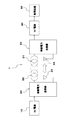
- FIG. 1 is a block diagram illustrating a configuration example of a wireless power supply system 1 as an embodiment according to the present invention. It is a block diagram which shows the structural example of the wireless power transmitter 20 and the wireless power receiver 30 as embodiment. 3 is a circuit diagram showing a configuration example of a power amplification unit 21 and a power conversion unit 32.
- FIG. 6 is a graph illustrating an example of a power feeding pattern characteristic in a storage unit 26. It is a table
- FIG. 6 is a plan view of a patchwork type biosensor 301 showing a mounting example (part 1) of the wireless power receiver 30; FIG.
- FIG. 6 is a perspective view of a ring-type biosensor 302 showing a mounting example (part 2) of the wireless power receiver 30.
- 6 is a plan view of a contact lens 303 showing a mounting example (No. 3) of the wireless power receiver 30.
- FIG. FIG. 6 is a plan view of a pinhole contact lens 304 showing a mounting example (part 4) of the wireless power receiver 30;
- 3 is a flowchart illustrating an example of control in the wireless power supply system 1.
- a medical wireless power supply system 1 shown in FIG. 1 is suitable for application to an interactive wireless power general-purpose power supply system or the like, and supplies wireless power from a power transmission side to a power reception side using an electromagnetic induction method.
- the interactive wireless power general-purpose power supply system means that a power transmission-side wireless power transmitter finds a power-receiving-side power supply pattern in response to a request from a power-receiving medical wireless power receiver, and based on the power supply pattern.
- the power transmission side has a DC power supply 10, a wireless power transmitter 20, a power transmission coil 22 and an antenna 23, and the power reception side has a wireless power receiver 30, a power reception coil 31, an antenna 34, and a DC power supply. 40 and a load circuit 50.
- the DC power source 10 is connected to the wireless power transmitter 20, and the power transmission coil 22 and the antenna 23 are connected to the wireless power transmitter 20.
- the wireless power transmitter 20 converts the output of the DC power source 10 into a high-frequency signal having a predetermined frequency and outputs the high-frequency signal to the power transmission coil 22.
- any one of the wireless power transmitters according to the present invention is used as the wireless power transmitter 20, and the wireless power transmitter 20 performs medical wireless communication based on the first power P1 at the initial stage of power feeding.
- the power supply information of the power receiver 30 is detected, and the second power P2 based on the power supply information is supplied to the wireless power receiver 30 during steady power supply.
- the power supply information refers to information indicating a power supply (charging condition) pattern to an object on which the wireless power receiver 30 is mounted.
- the power supply information includes code data indicating individual identification (charge type, etc.), and this code data forms a read code, such as 00001, 00002, 00003, 00004... For reading the power supply pattern. It functions as an address.
- the power supply information includes information indicating the charging capacity of the DC power supply 40 of the wireless power receiver 30, information indicating the end of charging of the DC power supply 40, information indicating the type of biosensor, and the like.
- the wireless power transmitter 20 is mounted on at least one of an external device that operates the load circuit 50 and a smartphone that can be connected to the Internet.
- an external device that operates the load circuit 50
- a smartphone that can be connected to the Internet.
- external devices headphones, earrings, brooches, watches, glasses, headbands, etc. that are portable and convenient to carry are mounted with DC power supply 10, wireless power transmitter 20, power transmission coil 22 and antenna 23. it can.
- the power receiving coil 31 and the antenna 34 are connected to the wireless power receiver 30 and the DC power source 40 is connected to the wireless power receiver 30.
- a load circuit 50 is connected to the DC power source 40.
- any wireless power transceiver according to the present invention is used.
- the wireless power receiver 30 receives the high-frequency signal via the power receiving coil 31 and supplies the load circuit 50 with the output of the DC power source 40 obtained by converting the high-frequency signal into direct current.
- the wireless power transmitter 20 illustrated in FIG. 2 includes a power amplification unit 21, a wireless communication unit 24, and a control unit 25.
- a DC power source 10, a power amplifying unit 21, and a wireless communication unit 24 are connected to the control unit 25, and a power transmission coil 22 is connected to the power amplifying unit 21.
- An antenna 23 is connected to the wireless communication unit 24.
- a power amplifying unit 21 is connected to the DC power source 10, and the power amplifying unit 21 (see FIG. 3) converts (modulates) the output of the DC power source 10 into a high frequency signal having a predetermined frequency f, and the high frequency signal is transmitted to the power transmission coil 22. It works to output.
- the wireless communication unit 24 receives power supply information from the wireless power receiver 30. The power supply information is for reading a power supply pattern.
- the wireless communication unit 24 can use a short-range wireless communication standard such as Bluetooth (registered trademark).
- the control unit 25 controls the output of the power amplifying unit 21 based on the power supply information obtained from the wireless communication unit 24. For example, the control unit 25 detects the power supply information of the wireless power receiver 30 based on the first power P1 at the initial stage of power supply, and the wireless power receiver 30 uses the second power P2 based on the power supply information at the time of steady power supply. Supply power to The relationship between the power P1 and the power P2 is P1 ⁇ P2.
- the power P1 is at least the minimum power that can be driven by the control unit 35 and the wireless communication unit 33, and the voltage is V0 and the current is I0 at the initial stage of power feeding.
- the electric power P2 is the electric power that can be charged to the storage battery 41.
- the voltage at the time of steady power supply is V1, V2, V3, V4... Larger than the voltage V0, and the current at that time is Ia, Ib , Id, Id,... Larger than the current I0 (see FIGS. 4 and 5).
- the electrolytic capacitor C1 and the storage battery 11 shown in FIG. A storage battery 11 is connected in parallel to the electrolytic capacitor C1, and the storage battery 11 is charged and used.
- the present invention is not limited to this, and a dry cell may be used, or power may be supplied via an AC-DC converter that operates on a commercial power source AC100.
- the storage battery 11 is a secondary battery such as a lithium ion battery.
- the + symbol of the electrolytic capacitor C1 indicates the high potential side, and GND is ground (earth).
- a power amplifying unit 21 is connected to the storage battery 11, and the output (DC voltage VDD) of the DC power source 10 is applied to the power amplifying unit 21.
- the power amplifying unit 21 includes a variable oscillator 201, gate drivers 202 and 203, capacitances C0, C2, C3, C11 and C21, variable capacitance C4, resistance elements R11, R12, R21 and R22, and a variable coil L.
- GaN semiconductor elements are used for the field effect transistors FET1 and FET2.
- Gate drivers 202 and 203 are connected to the variable oscillator 201 via a capacitance C0.
- the gate drivers 202 and 203 are connected between the DC power supply 10 and the ground line GND.
- the oscillation signal generated by the variable oscillator 201 is input to the gate drivers 202 and 203.
- the gate driver 202 is connected to a capacitance C11 and a resistance element R11 as circuit constant elements. One ends of the capacitance C11 and the resistance element R11 are grounded. Similarly, a capacitance C21 and a resistance element R21 are connected to the gate driver 203. One ends of the capacitance C21 and the resistance element R21 are grounded.
- the P-type field effect transistor FET1 is connected to the output of the gate driver 202 via a resistance element R12.
- the field effect transistor FET1 is turned on when a low level switching pulse signal is input to the gate, and is turned off when a high level switching signal is input.
- the P-type field effect transistor FET2 is also connected to the output of the gate driver 203 via the resistance element R22.
- the field effect transistor FET2 is also turned on when a low level switching pulse signal is input to the gate, and is turned off when a high level switching signal is input.
- the field effect transistors FET1 and FET2 constitute a class E push-pull power amplifier circuit.
- the sources of the field effect transistors FET1 and FET2 are grounded, and their drains are connected to the primary side of the transformer T, respectively.
- the midpoint of the primary side of the transformer T is connected to the DC power source 10 via the variable coil L, and the output (DC voltage VDD) of the DC power source 10 is applied to the midpoint via the variable coil L.
- the DC voltage VDD is supplied to the drains of the field effect transistors FET1 and FET2.
- the electrostatic capacity C2 is connected to the high potential side of the variable coil L.
- One end of the capacitance C2 is connected to the ground GND.
- a resistance element R1 is connected in series to the secondary side of the transformer T, and a capacitance C3 and a variable capacity C4 are connected in parallel to the other end of the resistance element R1, and the secondary side of the transformer T and the resistance element R1 are connected.
- the capacitance C3 and the variable capacitance C4 constitute a parallel resonance circuit.
- the control unit 25 includes a storage unit 26.
- the storage unit 26 has temperature-current supply characteristics, current-time supply characteristics, current-voltage supply characteristics, and voltage-time supply characteristics. At least one of the power supply patterns is stored. For example, in the graph shown in FIG. 4, the storage unit 26 stores data indicating a voltage-time power supply characteristic example on the power receiving side.
- the vertical axis represents voltage [V], the lower part is small, and the upper part is large.
- the horizontal axis is time [T], the left is small, and the right is large.
- the voltage V0 is a power supply initial voltage.
- the first power P1 is V0 ⁇ I0.
- V0 is about 2V.
- I0 is a unit of several [mA].
- the V0-T power supply characteristic is an initial power supply pattern.
- the voltage V1 is the first steady power supply voltage.
- the second power P21 is V1 ⁇ Ia.
- V1 is about 4V.
- the V1-T feed characteristic is the first steady feed pattern I.
- the voltage V2 is a second steady power supply voltage. If the steady power supply current is Ib (see FIG. 5), the second power P22 is V2 ⁇ Ib. For example, V2 is about 5V.
- the V2-T feeding characteristic is the second steady feeding pattern II.
- the voltage V3 is a third steady power supply voltage. If the steady power supply current is Ic (see FIG. 5), the second power P23 is V3 ⁇ Ic. For example, V3 is about 6V.
- the V3-T feeding characteristic is the third steady feeding pattern III.
- the voltage V4 is a fourth steady power supply voltage. When the steady power supply current is Id (see FIG. 5), the second power P24 is V4 ⁇ Id. For example, V4 is about 7V.
- the V4-T power supply characteristic is the fourth steady power supply pattern IV.
- Tx is the switching time between initial energization and steady energization. The switching time Tx is a time after an arbitrary settling time (determination period) has elapsed since the time when the voltage V0 was reached from the zero voltage. The shorter the settling time, the better.
- the feeding patterns I to IV are different depending on the object on which the wireless power receiver 30 is mounted. Note that description of the temperature-current feeding characteristics, current-time feeding characteristics, and current-voltage feeding characteristics is omitted.
- the wireless power receiver 30 illustrated in FIG. 2 includes a power conversion unit 32, a wireless communication unit 33, and a control unit 35 in order to capture a high frequency signal induced from the power transmission coil 22.
- the control unit 35 is connected to the power conversion unit 32, the wireless communication unit 33, and the DC power supply 40, and the power receiving coil 31 is connected to the power conversion unit 32.
- a DC power source 40 is connected to the power converter 32 and a load circuit 50 is connected to the DC power source 40.
- a power converter 32 is connected to the power receiving coil 31, and a high-frequency signal derived from the power transmitting coil 22 of the wireless power transmitter 20 is captured via the power receiving coil 31 and converted to direct current.
- the control unit 35 controls the power conversion unit 32 and the DC power supply 40 so as to supply DC power supplied with direct current from the power conversion unit 32 to the load circuit 50.
- the wireless communication unit 33 transmits the power supply information of the load circuit 50 to the wireless power transmitter 20 side through the antenna 34.
- the control unit 35 outputs the power supply information of the DC power supply 40 based on the first power P1 at the initial stage of power supply, and supplies the second power P2 based on the power supply information to the load circuit 50 at the time of steady power supply.
- the power conversion unit 32 shown in FIG. 3 includes, for example, a capacitance C5, diodes D1 to D4, and a resistance element R2.
- the electrostatic capacitance C5 is connected in parallel to the power receiving coil 31, and constitutes a resonance circuit together with the power receiving coil 31.
- the diodes D1 to D4 constitute a full-wave rectifier circuit, and convert the high-frequency signal acquired from the power receiving coil 31 into direct current.
- Electrolytic capacitor C6 is connected to the outputs of diodes D1 to D4, and electrolytic capacitor C6 smoothes the pulsating flow to direct current.
- the LED is connected in series between the connection point of the diodes D1 and D2 and the load circuit 50, and is used for energization display and circuit protection.
- an electrolytic capacitor C6 and a storage battery 41 constitute a DC power source 40.
- a storage battery 41 is connected in parallel to the electrolytic capacitor C6, and the storage battery 41 is charged.
- the + symbol of the electrolytic capacitor C6 indicates the high potential side, and GND is ground (earth).
- a load circuit 50 is connected to the storage battery 41, and a resistance element R2 for circuit protection is connected to the load circuit 50 in parallel.
- a detection unit 51 is provided in the load circuit 50 that receives power supply from the DC power supply 40, and the power supply information includes information indicating a predetermined detection amount obtained from the detection unit 51.
- the detection unit 51 detects the temperature ⁇ of the storage battery 41 during charging and generates a temperature detection signal.
- the temperature detection signal is binarized and becomes power supply information.
- the terminal voltage V of the storage battery 41 is binarized and becomes power supply information.
- a wireless power receiver 30 shown in FIG. 6 constitutes a patchwork type biosensor 301 in the wireless power supply system 1.
- the patchwork type biosensor 301 includes a wireless power receiver 30, a power receiving coil 31, an antenna 34, a DC power supply 40, a detection unit 51, and a base 71.
- the power receiving coil 31 and the antenna 34 are arranged on the outer peripheral edge of the base 71, and the power conversion unit 32, the wireless communication unit 33, the control unit 35, the DC power source 40, and the detection in the same base.
- the part 51 is integrally arranged to constitute a sensor module.
- the patchwork type biosensor 301 is used by being attached to the skin surface.
- a flexible material such as cotton tape or medical tape is used. Stretchable material can be used.
- the detection unit 51 of this example includes a biological sensor that detects biological information of a living thing.
- a glucose sensor for self blood glucose level management that measures the blood glucose level can be used.
- Glucose Oxidase (GOD) is used for the glucose sensor, and the measurement principle is that GOD is immobilized in a polymer gel such as polyacrylamide, and oxygen consumption in the vicinity of the electrode accompanying the enzyme reaction is measured by the electrode response ( By grasping it as a decrease in the current value, the glucose concentration is selectively measured.
- a minute nanostructured oxide semiconductor is embedded in a biosensor, and a transparent device detects the minute glucose concentration in tears.
- the enzyme oxidizes blood sugar when in contact with tear glucose. This changes the pH level in the mixture and causes a measurable change in the current of the IGZO transistor.
- Tears contain a lot of detectable information. Tears contain not only glucose but also information on lactic acid (sepsis / liver disease), dopamine (glaucoma), urea (renal function), and protein (cancer).
- the wireless power receiver 30 shown in FIG. 7 constitutes a ring-type biosensor 302 in the wireless power supply system 1.
- the ring-type biosensor 302 includes a wireless power receiver 30, a power receiving coil 31, an antenna 34, a DC power supply 40, a detection unit 51, a base 72, and a ring unit 73.
- the ring-type biosensor 302 has the power receiving coil 31 and the antenna 34 disposed in the outer peripheral edge of the base 72, and the power conversion unit 32, the wireless communication unit 33, the control unit 35, the DC power source 40, and the detection unit 51 are integrally disposed. Then, the integrated sensor module is fixed to the ring portion 73.
- the ring part 73 is used by fitting to the finger part.
- the ring-type biosensor 302 is used by being attached to any of the index finger, middle finger, ring finger, little finger, and the like.
- a photoelectric pulse wave sensor is used for the ring-type biological sensor 302.
- the photoelectric pulse wave sensor uses the light absorption characteristics of hemoglobin in the blood, receives the reflected light of the infrared light irradiated to the blood vessel of the finger by the internal light emitting element, and captures pulsation etc. from the intensity change It is made like.
- a wireless communication module that conforms to the low-power Bluetooth low Energy standard (registered trademark) is used.
- the wireless power receiver 30 shown in FIG. 8 constitutes the contact lens type biosensor 303 in the wireless power feeding system 1.
- the contact lens type biosensor 303 includes a wireless power receiver 30, a power receiving coil 31, an antenna 34, a DC power supply 40, a detection unit 51, and a lens body 74.
- the lens body 74 includes a soft contact lens and a hard contact lens.
- the contact lens type biosensor 303 In the contact lens type biosensor 303, the power receiving coil 31, the power conversion unit 32, the wireless communication unit 33, the antenna 34, the control unit 35, the DC power source 40, and the detection unit 51 are integrated on the outer peripheral edge of the lens body 74. It is arranged and constitutes a sensor module.
- the contact lens type biosensor 303 is worn on the cornea.
- a wireless power receiver 30 shown in FIG. 9 constitutes a pinhole contact lens type biosensor 304 in the wireless power supply system 1.
- the pinhole contact lens type biosensor 304 includes a wireless power receiver 30, a power receiving coil 31, an antenna 34, a DC power supply 40, a detection unit 51, and a pinhole lens main body 75.
- the pinhole lens main body 75 has a light shielding portion 76 and a pinhole 77.
- the power receiving coil 31 and the antenna 34 are disposed on the outer peripheral edge of the pinhole lens body 75, and the power conversion unit 32, the radio communication unit 33, the control unit 35, The DC power supply 40 and the detection unit 51 are integrated to constitute a sensor module.
- the pinhole contact lens type biosensor 304 is also worn on the cornea.
- the contact lens type biosensor and the pinhole contact lens type biosensor described above constitute a smart contact lens.
- the semiconductor elements integrated circuit itself: several mm square
- the insulating light-shielding portion 76 is formed so as to electrically insulate the semiconductor elements in common, and at the same time, the black color of the light-shielding portion 76 (high light shielding rate) is realized.
- the insulating structure between the elements of the semiconductor chip can be made common, and the mounting chip (for example, 1.6 mm ⁇ 1.6 mm microcomputer chip) can be miniaturized and thinned.
- the sensor module includes a patchwork-type biosensor 301, a smart contact lens, a ring-type biosensor 302, and an in-vivo sensor.
- a continuous glucose monitor (CGM) that can continuously monitor the glucose concentration by developing a glucose sensor has been developed. According to CGM, interstitial fluid in the skin is sucked in painlessly, absorbed in a patch containing GOD, and the glucose concentration is quantified with a hydrogen peroxide electrode.
- the wireless power receiver 30 is mounted on a contact lens on the power receiving side, and the power supply information of this contact lens is the power supply pattern II shown in FIG. Assume a case. *
- control unit 25 (hereinafter referred to as the power transmission side) of the wireless power transmitter 20 outputs the first power P1 for starting up the wireless power receiver 30 in step S11 of the flowchart shown in FIG.
- the power amplifying unit 21 is controlled as described above.
- the power conversion unit 32 receives from the wireless power transmitter 20 the first power P1 for starting up the control unit 35 in step S21.
- the power P1 is, for example, a voltage V0 and a feeding current I0.
- step S22 the wireless communication unit 33 transmits power supply information to the wireless power transmitter 20 via the antenna 34 when the control unit 35 is started up.
- step S13 the control unit 25 detects the power supply information and determines it.
- Control data D Ib, V2, and ⁇ 2 are control targets on the power receiving side.
- the frequency f is a power transmission target value, and the voltage of the high frequency signal on the power transmission side can be controlled.
- step S14 the control unit 25 determines the output of the power amplification unit 21 based on the power supply information.
- the current / voltage of the high-frequency signal on the power transmission side is determined by the turns ratio of the transformer T.
- Vn1 is achieved by adjusting the variable coil L.
- the current of the high-frequency signal on the power transmission side achieves the target value of the current Ib on the power reception side by adjusting the variable capacitor C4.
- step S15 the control unit 25 supplies the second power P2 (P1 ⁇ P2) based on the determined output of the power amplification unit 21 to the wireless power receiver 30.
- step S23 the control unit 35 controls the power conversion unit 32 to receive the second power P2 based on the output of the wireless power transmitter 20 determined based on the power supply information.
- step S26 power is supplied to the load circuit 50 (step S26) and the storage battery 41 can be charged.
- step S24 the control unit 35 determines whether or not the storage battery 41 is fully charged. Whether or not the battery is fully charged is determined, for example, by measuring the terminal voltage (V2) of the storage battery 41 and reaching a specified value. When the battery is not fully charged, the process returns to step S22, and power supply information is returned to the power transmission side via the wireless communication unit 33 and the antenna 34.
- V2 terminal voltage
- charging completion information is transmitted to the power transmission side via the wireless communication part 33 and the antenna 34 at step S25.
- the control unit 25 turns off the power supply.
- the control unit 25 resets the second power P2 set after the determination to the initial first power P1, and prepares for the next initial power supply (reset operation).
- the wireless power transmitter 20 finds a power supply pattern on the power receiving side in response to a request from the wireless power receiver 30, and the DC power supply 40 is based on the power supply pattern.
- the storage battery 41 according to the method is charged.
- the wireless power receiver 30 can be started up with the first power P1 lower than the second power P2 at the time of steady power supply at the initial stage of power supply. That is, the first power P1 for starting up the wireless power receiver 30 can be suppressed to be lower than the second power P2 based on the output of the determined power amplification unit 21 at the initial stage of power supply.
- the power supply information of the DC power source 40 of the wireless power receiver 30, such as the charging capacity and the charging temperature, can be detected (recognized) on the power transmission side before charging.
- the wireless power receiver 30 it is possible to reduce the power supply shock, circuit stress, etc. at the initial stage of power supply as much as possible, and overcharge of the DC power source 40 on the power receiving side and unintentional heat generation. Can be prevented.
- the above-described insulating sealing structure can make the inter-element insulating structure of the semiconductor chip common, and the mounted chip can be miniaturized and thinned. As a result, the minimum necessary semiconductor chip can be efficiently mounted on a contact lens having a small mounting area. For example, the memory area for storing the address code can be kept to a minimum.
- the output of the high-frequency signal transmitted from the wireless power transmitter can be adjusted (selected) according to the charge capacity on the power receiving side, or the output of the high-frequency signal can be stopped based on information indicating the end of charging. Become. Thereby, an interactive wireless communication general-purpose charging system or the like can be constructed.
- the electromagnetic induction (electromagnetic coupling) method has been described with respect to the wireless power feeding system 1.
- the present invention is not limited to this, and a magnetic resonance method as shown in Japanese Patent No. 6056477 may be used.
- the LC resonance circuit 60 is arranged close to the power transmission side and the power reception side in a non-contact manner.
- the LC resonance circuit 60 is designed to have a predetermined resonance frequency and a very high Q value.
- the resonance frequencies of the LC resonance circuit 60 on the power transmission side and the power reception side are both set equal.
- L ′ is a resonance coil (inductor)
- C ′ is a variable capacitor (capacitor).
- the LC resonance circuit 60 on the power transmission side is arranged at a predetermined interval so that its center axis coincides with the center axis of the LC resonance circuit 60 on the power reception side.
- the distance between the LC resonance circuit 60 on the power transmission side and the power reception side may be about several meters. If the resonance Q of the LC resonance circuit 60 is sufficiently large, electric power can be transmitted by magnetic field resonance even if it is several meters away.
- the reason why the central axes coincide is to cause good magnetic field resonance between the LC resonance circuit 60 on the power transmission side and the power reception side.
- the present invention is not limited to this, and according to the magnetic field resonance method, the power transmission coil 22 and the power reception coil 31 are used. There is also a merit that it is stronger than the electromagnetic induction method.
- the distance or position shift between the LC resonance circuits 60 has a higher degree of freedom than the electromagnetic induction method, and is characterized by position free.
- the LC resonance circuit 60 does not have to be arranged with the central axes coincident with each other, and may be arranged in a positional relationship having an angle with each other.
- the diameter of the LC resonance circuit 60 is different on the power transmission side and the power reception side. Also good.
- the diameter of the LC resonance circuit 60 may differ by about 10 times between the power transmission side and the power reception side. This is because power transmission by magnetic field resonance is different from power transmission by electromagnetic induction using electromagnetic field coupling, and power can be transmitted even if the separation distance between the LC resonance circuit 60 on the power transmission side and the power reception side is somewhat separated. Because.
- the GOD method (one of the enzyme electrode methods) has been described with respect to the measurement of the blood glucose level.
- the present invention is not limited to this, and a glucose dehydrogenase (GDH) method, which is another example of the enzyme electrode method, is used. May be used.
- GDH glucose dehydrogenase
- GDH in the glucose sensor reacts with glucose in the blood to generate gluconolactone and electrons.
- the ferricyanide ion contained in the glucose sensor changes to reduced ferricyanide ion, and again oxidizes to ferricyanide ion, generating an electromotive force at the electrode, which is the concentration of glucose in the blood.
- an electromotive force at the electrode, which is the concentration of glucose in the blood.
- the present invention is not limited to this.
- a simultaneous power supply method of supplying power to the plurality of wireless power receivers 30 at the same time may be employed.
- SYMBOLS 1 ... Wireless power feeding system, 10, 40 ... DC power supply, 11.41 ... Storage battery, 20 ... Wireless power transmitter, 21 ... Power amplification part, 22 ... Power transmission coil, 23, 34 ... antenna, 24, 33 ... wireless communication unit, 25, 35 ... control unit, 26 ... storage unit, 30 ... wireless power receiver, 31 ... receiving coil, 32 ... Power conversion unit, 50 ... Load circuit, 51 ... Detection unit, 60 ... LC resonance circuit
Landscapes
- Health & Medical Sciences (AREA)
- Life Sciences & Earth Sciences (AREA)
- Engineering & Computer Science (AREA)
- Physics & Mathematics (AREA)
- Molecular Biology (AREA)
- General Health & Medical Sciences (AREA)
- Power Engineering (AREA)
- Biophysics (AREA)
- Veterinary Medicine (AREA)
- Biomedical Technology (AREA)
- Heart & Thoracic Surgery (AREA)
- Medical Informatics (AREA)
- Public Health (AREA)
- Surgery (AREA)
- Animal Behavior & Ethology (AREA)
- Computer Networks & Wireless Communication (AREA)
- Pathology (AREA)
- Optics & Photonics (AREA)
- Cardiology (AREA)
- Physiology (AREA)
- Ophthalmology & Optometry (AREA)
- Charge And Discharge Circuits For Batteries Or The Like (AREA)
- Measuring Pulse, Heart Rate, Blood Pressure Or Blood Flow (AREA)
- Measurement Of The Respiration, Hearing Ability, Form, And Blood Characteristics Of Living Organisms (AREA)
- Eye Examination Apparatus (AREA)
Abstract
La présente invention permet d'empêcher la surcharge d'un bloc d'alimentation en courant continu et la génération de chaleur indésirable du côté réception d'énergie au moment de l'alimentation électrique en régime permanent, sans provoquer de choc d'alimentation, de contrainte de circuit ou similaire pour affecter le côté réception d'énergie au moment initial de l'alimentation électrique. Un système d'alimentation électrique sans fil 1 comprend : un émetteur d'énergie sans fil 20 qui convertit la sortie d'un bloc d'alimentation en courant continu 10 côté transmission d'énergie en un signal haute fréquence d'une fréquence prescrite, et délivre le signal haute fréquence à une bobine de transmission d'énergie 22 ; et un récepteur d'énergie sans fil 30 qui reçoit le signal haute fréquence par l'intermédiaire d'une bobine de réception d'énergie 31, et fournit à un circuit de charge 50 la sortie d'un bloc d'alimentation en courant continu 40 qui a converti le signal haute fréquence en un courant continu. L'émetteur d'énergie sans fil 20 détecte les informations d'alimentation électrique du récepteur d'énergie sans fil 30 sur la base d'une première puissance P1 au moment de l'alimentation électrique initiale, et au moment de l'alimentation électrique en régime permanent, fournit une seconde puissance P2 sur la base des informations d'alimentation électrique au récepteur d'énergie sans fil 30. La première puissance P1 est inférieure à la seconde puissance P2.
Applications Claiming Priority (2)
| Application Number | Priority Date | Filing Date | Title |
|---|---|---|---|
| JP2017088421A JP2018186683A (ja) | 2017-04-27 | 2017-04-27 | 無線電力送信器、無線電力受信器及び無線電力給電システム |
| JP2017-088421 | 2017-04-27 |
Publications (1)
| Publication Number | Publication Date |
|---|---|
| WO2018199057A1 true WO2018199057A1 (fr) | 2018-11-01 |
Family
ID=63919006
Family Applications (1)
| Application Number | Title | Priority Date | Filing Date |
|---|---|---|---|
| PCT/JP2018/016531 WO2018199057A1 (fr) | 2017-04-27 | 2018-04-24 | Émetteur d'énergie sans fil, récepteur d'énergie sans fil à usage médical, et système d'alimentation électrique sans fil associé |
Country Status (2)
| Country | Link |
|---|---|
| JP (1) | JP2018186683A (fr) |
| WO (1) | WO2018199057A1 (fr) |
Families Citing this family (1)
| Publication number | Priority date | Publication date | Assignee | Title |
|---|---|---|---|---|
| KR102512150B1 (ko) * | 2021-01-29 | 2023-03-20 | 홍익대학교 산학협력단 | 모아레 렌즈를 이용한 무선 전력 전송 장치 |
Citations (5)
| Publication number | Priority date | Publication date | Assignee | Title |
|---|---|---|---|---|
| JPH10314318A (ja) * | 1997-05-21 | 1998-12-02 | Kaajiopeeshingu Res Lab:Kk | 心臓ペースメーカ装置 |
| WO2015064473A1 (fr) * | 2013-10-28 | 2015-05-07 | 京セラ株式会社 | Dispositif de commande |
| WO2016125227A1 (fr) * | 2015-02-02 | 2016-08-11 | 三菱電機株式会社 | Dispositif de transmission d'énergie sans contact, appareil électrique, et système de transmission d'énergie sans contact |
| JP2016531662A (ja) * | 2013-07-29 | 2016-10-13 | アルフレッド イー. マン ファウンデーション フォー サイエンティフィック リサーチ | 無線リンクによる埋め込み充電場制御 |
| JP2017017988A (ja) * | 2016-09-05 | 2017-01-19 | ソニー株式会社 | 端末装置 |
Family Cites Families (7)
| Publication number | Priority date | Publication date | Assignee | Title |
|---|---|---|---|---|
| JP2004513681A (ja) * | 2000-07-21 | 2004-05-13 | メドトロニック,インコーポレイテッド | 生体パラメータを測定しかつ通信する装置及び方法 |
| US9132276B2 (en) * | 2010-12-10 | 2015-09-15 | Cochlear Limited | Portable power charging of implantable medical devices |
| JP2012223070A (ja) * | 2011-04-14 | 2012-11-12 | Sony Corp | 電力制御装置、電力制御方法、およびプログラム |
| US9079043B2 (en) * | 2011-11-21 | 2015-07-14 | Thoratec Corporation | Transcutaneous power transmission utilizing non-planar resonators |
| US9270134B2 (en) * | 2012-01-27 | 2016-02-23 | Medtronic, Inc. | Adaptive rate recharging system |
| US9504842B2 (en) * | 2013-07-23 | 2016-11-29 | Ado Holding Sa | Electronic medical system with implantable medical device, having wireless power supply transfer |
| KR102337934B1 (ko) * | 2014-11-04 | 2021-12-13 | 삼성전자주식회사 | 무선 충전으로 전력을 공유하기 위한 전자 장치 및 방법 |
-
2017
- 2017-04-27 JP JP2017088421A patent/JP2018186683A/ja active Pending
-
2018
- 2018-04-24 WO PCT/JP2018/016531 patent/WO2018199057A1/fr active Application Filing
Patent Citations (5)
| Publication number | Priority date | Publication date | Assignee | Title |
|---|---|---|---|---|
| JPH10314318A (ja) * | 1997-05-21 | 1998-12-02 | Kaajiopeeshingu Res Lab:Kk | 心臓ペースメーカ装置 |
| JP2016531662A (ja) * | 2013-07-29 | 2016-10-13 | アルフレッド イー. マン ファウンデーション フォー サイエンティフィック リサーチ | 無線リンクによる埋め込み充電場制御 |
| WO2015064473A1 (fr) * | 2013-10-28 | 2015-05-07 | 京セラ株式会社 | Dispositif de commande |
| WO2016125227A1 (fr) * | 2015-02-02 | 2016-08-11 | 三菱電機株式会社 | Dispositif de transmission d'énergie sans contact, appareil électrique, et système de transmission d'énergie sans contact |
| JP2017017988A (ja) * | 2016-09-05 | 2017-01-19 | ソニー株式会社 | 端末装置 |
Also Published As
| Publication number | Publication date |
|---|---|
| JP2018186683A (ja) | 2018-11-22 |
Similar Documents
| Publication | Publication Date | Title |
|---|---|---|
| US11986290B2 (en) | Analyte sensor | |
| US11777340B2 (en) | Charging case for electronic contact lens | |
| US9380971B2 (en) | Method and system for powering an electronic device | |
| CN104662787B (zh) | 用于感应电力传输的反馈控制线圈驱动器 | |
| EP2889982B1 (fr) | Appareil de transmission de puissance sans fil et appareil de chargement d'énergie | |
| Li et al. | Body-area powering with human body-coupled power transmission and energy harvesting ICs | |
| US20180126053A1 (en) | Wristwatch for monitoring operation of an implanted ventricular assist device | |
| US10372179B1 (en) | Performing a power cycle reset in response to a change in charging power applied to an electronic device | |
| TW202033152A (zh) | 眼用裝置的光通訊 | |
| US20240028535A1 (en) | Remotely-powered sensing system with multiple sensing devices | |
| WO2018199057A1 (fr) | Émetteur d'énergie sans fil, récepteur d'énergie sans fil à usage médical, et système d'alimentation électrique sans fil associé | |
| Pandey et al. | Toward an active contact lens: Integration of a wireless power harvesting IC | |
| Nguyen et al. | A smart health tracking ring powered by wireless power transfer | |
| US20180254631A1 (en) | Power Receiving Unit For Charging While In Pre-Overvoltage Protection | |
| US7912547B2 (en) | Device for optimizing transmitting energy and transmitting position for an implantable electrical stimulator | |
| CN100508876C (zh) | 人体生理状态检测腕表 | |
| Olivo et al. | Electronic implants: Power delivery and management | |
| US9399142B2 (en) | Implantable medical device and system | |
| Leoni et al. | RF energy harvested sensory headwear for quadriplegic people | |
| CN205377465U (zh) | 可提示调整位置的无线充电器及可充电植入式医疗器械 | |
| Liu et al. | Body-based capacitive coupling and conductive channel power transfer for wearable and implant electronics | |
| EP3261529B1 (fr) | Capteur d'analyte et procédé d'utilisation de capteur d'analyte | |
| Kuwana et al. | Implantable telemetry capsule for monitoring arterial oxygen saturation and heartbeat | |
| Chaari et al. | Overview and Challenges of Wireless Communication and Power Transfer for Implanted Sensors | |
| Dentis | Wireless Charging and Power Management System for Biomedical Implantable Devices |
Legal Events
| Date | Code | Title | Description |
|---|---|---|---|
| 121 | Ep: the epo has been informed by wipo that ep was designated in this application |
Ref document number: 18790366 Country of ref document: EP Kind code of ref document: A1 |
|
| NENP | Non-entry into the national phase |
Ref country code: DE |
|
| 122 | Ep: pct application non-entry in european phase |
Ref document number: 18790366 Country of ref document: EP Kind code of ref document: A1 |