WO2018198914A1 - Transmission apparatus, transmission method, reception apparatus, and reception method - Google Patents
Transmission apparatus, transmission method, reception apparatus, and reception method Download PDFInfo
- Publication number
- WO2018198914A1 WO2018198914A1 PCT/JP2018/016063 JP2018016063W WO2018198914A1 WO 2018198914 A1 WO2018198914 A1 WO 2018198914A1 JP 2018016063 W JP2018016063 W JP 2018016063W WO 2018198914 A1 WO2018198914 A1 WO 2018198914A1
- Authority
- WO
- WIPO (PCT)
- Prior art keywords
- frame
- mixing
- rate
- video data
- frames
- Prior art date
Links
- 230000005540 biological transmission Effects 0.000 title claims abstract description 99
- 238000000034 method Methods 0.000 title claims description 24
- 238000002156 mixing Methods 0.000 claims abstract description 368
- 238000012545 processing Methods 0.000 claims abstract description 235
- 230000002093 peripheral effect Effects 0.000 claims abstract description 75
- 238000012546 transfer Methods 0.000 claims description 27
- 230000000153 supplemental effect Effects 0.000 claims description 3
- 238000010586 diagram Methods 0.000 description 29
- 238000005516 engineering process Methods 0.000 description 23
- 239000000284 extract Substances 0.000 description 11
- 230000002123 temporal effect Effects 0.000 description 7
- 238000001914 filtration Methods 0.000 description 5
- 230000008569 process Effects 0.000 description 4
- 101100243456 Arabidopsis thaliana PES2 gene Proteins 0.000 description 3
- 101001073193 Homo sapiens Pescadillo homolog Proteins 0.000 description 3
- 102100035816 Pescadillo homolog Human genes 0.000 description 3
- 230000008901 benefit Effects 0.000 description 3
- 238000004891 communication Methods 0.000 description 3
- 238000003780 insertion Methods 0.000 description 3
- 230000037431 insertion Effects 0.000 description 3
- 238000012986 modification Methods 0.000 description 3
- 230000004048 modification Effects 0.000 description 3
- 230000008859 change Effects 0.000 description 2
- 238000003384 imaging method Methods 0.000 description 2
- 208000031509 superficial epidermolytic ichthyosis Diseases 0.000 description 2
- 230000001360 synchronised effect Effects 0.000 description 2
- 244000287680 Garcinia dulcis Species 0.000 description 1
- 230000004075 alteration Effects 0.000 description 1
- 230000015556 catabolic process Effects 0.000 description 1
- 238000006731 degradation reaction Methods 0.000 description 1
- 238000013461 design Methods 0.000 description 1
- 230000000694 effects Effects 0.000 description 1
- 239000000463 material Substances 0.000 description 1
- 239000000203 mixture Substances 0.000 description 1
- 230000000750 progressive effect Effects 0.000 description 1
- 230000011664 signaling Effects 0.000 description 1
Images


Classifications
-
- H—ELECTRICITY
- H04—ELECTRIC COMMUNICATION TECHNIQUE
- H04N—PICTORIAL COMMUNICATION, e.g. TELEVISION
- H04N21/00—Selective content distribution, e.g. interactive television or video on demand [VOD]
- H04N21/20—Servers specifically adapted for the distribution of content, e.g. VOD servers; Operations thereof
- H04N21/23—Processing of content or additional data; Elementary server operations; Server middleware
- H04N21/234—Processing of video elementary streams, e.g. splicing of video streams or manipulating encoded video stream scene graphs
- H04N21/2343—Processing of video elementary streams, e.g. splicing of video streams or manipulating encoded video stream scene graphs involving reformatting operations of video signals for distribution or compliance with end-user requests or end-user device requirements
- H04N21/234381—Processing of video elementary streams, e.g. splicing of video streams or manipulating encoded video stream scene graphs involving reformatting operations of video signals for distribution or compliance with end-user requests or end-user device requirements by altering the temporal resolution, e.g. decreasing the frame rate by frame skipping
-
- H—ELECTRICITY
- H04—ELECTRIC COMMUNICATION TECHNIQUE
- H04N—PICTORIAL COMMUNICATION, e.g. TELEVISION
- H04N19/00—Methods or arrangements for coding, decoding, compressing or decompressing digital video signals
- H04N19/30—Methods or arrangements for coding, decoding, compressing or decompressing digital video signals using hierarchical techniques, e.g. scalability
-
- H—ELECTRICITY
- H04—ELECTRIC COMMUNICATION TECHNIQUE
- H04N—PICTORIAL COMMUNICATION, e.g. TELEVISION
- H04N21/00—Selective content distribution, e.g. interactive television or video on demand [VOD]
- H04N21/20—Servers specifically adapted for the distribution of content, e.g. VOD servers; Operations thereof
- H04N21/23—Processing of content or additional data; Elementary server operations; Server middleware
- H04N21/235—Processing of additional data, e.g. scrambling of additional data or processing content descriptors
- H04N21/2355—Processing of additional data, e.g. scrambling of additional data or processing content descriptors involving reformatting operations of additional data, e.g. HTML pages
-
- H—ELECTRICITY
- H04—ELECTRIC COMMUNICATION TECHNIQUE
- H04N—PICTORIAL COMMUNICATION, e.g. TELEVISION
- H04N21/00—Selective content distribution, e.g. interactive television or video on demand [VOD]
- H04N21/20—Servers specifically adapted for the distribution of content, e.g. VOD servers; Operations thereof
- H04N21/23—Processing of content or additional data; Elementary server operations; Server middleware
- H04N21/236—Assembling of a multiplex stream, e.g. transport stream, by combining a video stream with other content or additional data, e.g. inserting a URL [Uniform Resource Locator] into a video stream, multiplexing software data into a video stream; Remultiplexing of multiplex streams; Insertion of stuffing bits into the multiplex stream, e.g. to obtain a constant bit-rate; Assembling of a packetised elementary stream
- H04N21/23605—Creation or processing of packetized elementary streams [PES]
-
- H—ELECTRICITY
- H04—ELECTRIC COMMUNICATION TECHNIQUE
- H04N—PICTORIAL COMMUNICATION, e.g. TELEVISION
- H04N21/00—Selective content distribution, e.g. interactive television or video on demand [VOD]
- H04N21/20—Servers specifically adapted for the distribution of content, e.g. VOD servers; Operations thereof
- H04N21/25—Management operations performed by the server for facilitating the content distribution or administrating data related to end-users or client devices, e.g. end-user or client device authentication, learning user preferences for recommending movies
- H04N21/266—Channel or content management, e.g. generation and management of keys and entitlement messages in a conditional access system, merging a VOD unicast channel into a multicast channel
- H04N21/2662—Controlling the complexity of the video stream, e.g. by scaling the resolution or bitrate of the video stream based on the client capabilities
-
- H—ELECTRICITY
- H04—ELECTRIC COMMUNICATION TECHNIQUE
- H04N—PICTORIAL COMMUNICATION, e.g. TELEVISION
- H04N23/00—Cameras or camera modules comprising electronic image sensors; Control thereof
- H04N23/95—Computational photography systems, e.g. light-field imaging systems
- H04N23/951—Computational photography systems, e.g. light-field imaging systems by using two or more images to influence resolution, frame rate or aspect ratio
Definitions
- the present technology relates to a transmission apparatus, a transmission method, a reception apparatus, and a reception method, and more particularly to a transmission apparatus that transits moving image data at a high frame rate and the like.
- a camera that performs high frame rate imaging with a high-speed frame shutter is known.
- a normal frame rate is 60 Hz, 50 Hz, or the like while the high frame rate is a frame rate that is several times, several tens of times, or further several hundreds of times as high as the normal frame rate.
- a transmission apparatus that performs processing of mixing, at a mixing rate for each frame, a frame of first video data with one or more peripheral frames of the first video data and obtains second video data at a first frame rate.
- the second video data includes frames corresponding to a second frame rate that is lower than the first frame rate, where the frames corresponding to the second frame rate being mixed with the peripheral frames.
- the transmission apparatus encodes the frames corresponding to the second frame rate to obtain a basic stream and encodes remaining frames of the second video data to obtain an extended stream.
- the transmission apparatus then inserts information about the mixing rate of corresponding frames into the basic stream and the extended stream in association with the respective frames, and transmits the basic stream and the extended stream into which the information about the mixing rate has been inserted.
- the basic stream and the extended stream have a Network Abstraction Layer (NAL) unit structure
- the transmission apparatus inserts a Supplemental Enhancement Information (SEI) NAL unit with the information about the mixing rate into the basic stream and the extended stream.
- SEI Supplemental Enhancement Information
- the first frame rate is 120 Hz or 240 Hz
- the second frame rate is 60 Hz.
- Information about the mixing rate which is inserted into the basic stream and the extended stream, may include configuration information of a filter used to perform the mixing processing.
- the information about the mixing rate may also include mixing refresh information indicating a number of frames until mixing refresh that does not use a temporally previous frame is performed.
- the information about the mixing rate may also include refresh flag information indicating whether or not a respective frame is a target of the mixing refresh.
- the information about the mixing rate may also include head flag information indicating whether or not a respective frame corresponds to the second frame rate.
- At least the frame corresponding to the second frame rate (normal frame rate) in each frame that forms the second video data at the first frame rata (high frame rate) is mixed with the peripheral frames and is in a state in which an aperture ratio is raised, and the basic stream obtained by encoding the frame corresponding to the second frame rate (normal frame rate) is transmitted as described above.
- the extended stream obtained by encoding the remaining frames is obtained along with the basic stream, and the information about the mixing rate of the corresponding frames is inserted into the basic stream and the extended stream in association with the respective frames, and the extended stream is then transmitted. Therefore, in a case of a receiver that has decoding ability with which the video data at the first frame rate (high frame rate) can be processed, it is possible to easily obtain the mixing-released video data at the first frame rate on the basis of the information about the mixing rate in each frame and to satisfactorily display the moving image at the first frame rate.
- a reception apparatus that receives a basic stream and an extended stream, which are obtained by performing processing of mixing, at a mixing rate for each frame, a frame of first video data with one or more peripheral frames of the first video data.
- the reception apparatus obtains second video data at a first frame rate, the second video data including frames corresponding to a second frame rate that is lower than the first frame rate.
- the reception apparatus mixes the frames corresponding to the second frame rate with the peripheral frames and encodes the frames corresponding to the second frame rate to obtain the basic stream.
- the reception apparatus encodes remaining frames of the second video data to obtain the extended stream.
- Information about the mixing rate of corresponding frames is included in the basic stream and the extended stream in association with the respective frames.
- the reception apparatus further decodes, based on a frame rate capability of a display connected to the reception apparatus, either the basic stream to obtain frames at the second frame rate or the basic stream and the extended stream to obtain the second video data, and, in the latter case, obtains mixing-released video data at the first frame rate by performing back mixing processing on the second video data on a basis of the information about the mixing rate.
- the video data at the second frame rate is obtained by processing only the basic stream in a case in which there is decoding ability with which the video data at the second frame rate (normal frame rate) as described above. Since the image data in each frame that forms the video data at the second frame rate (normal frame rate) is mixed with the peripheral frames, and a shutter aperture ratio is raised, it is possible to display a smooth image as a moving image and to avoid occurrence of a problem in image quality in the frame interpolation processing based on low load computation in the display processing.
- both the basic stream and the extended stream are processed to obtain the video data at the first frame rate (high frame rate) after the mixing processing, and further, the back mixing processing is performed on the basis of the information about the mixing rate in each frame to obtain the mixing-released video data at the first frame rate (normal frame rate) in a case in which there is decoding ability with which the video data at the first frame rate (high frame rate) can be processed. Therefore, it is possible to satisfactorily display the moving image at the first frame rate (high frame rate).
- a reception apparatus that acquires second video data obtained by performing processing of mixing, at a mixing rate for each frame, a frame of first video data with one or more peripheral frames of the first video data.
- the reception apparatus then transmits the second video data and information about the mixing rate in each frame to an external device via a transfer path.
- synchronization frame information indicating whether or not it is necessary to synchronize with a next video frame is included in the information about the mixing rate.
- the reception apparatus respectively inserts the information about the mixing rate in each frame into a blanking period of each frame of the second video data and transmits the second video data.
- the reception apparatus performs back mixing processing on each frame of the second video data on a basis of the information about the mixing rate to obtain third video data.
- the reception apparatus then transmits the third video data instead of the second video data when the external device does not have a function of the back mixing processing.
- the second video data has a first frame rate
- the second video data includes frames corresponding to a second frame rate that is lower than the first frame rate
- the frames corresponding to the second frame rate are mixed with the peripheral frames.
- the reception apparatus then transmits fourth video data that includes the frames corresponding to the second frame rate instead of the second video data when a frame rate at which display is able to be performed by the external device is the second frame rate.
- a reception apparatus that receives second video data obtained by performing processing of mixing, at a mixing rate for each frame, a frame of first video data with one or more peripheral frames of the first video data.
- the reception apparatus also receives information about a mixing rate in each frame from an external device via a transfer path.
- the reception apparatus then obtains mixing-released video data by performing back mixing processing on each frame of the second video data on a basis of the information about the mixing rate.
- the information about the mixing rate in each frame is received along with the second video data after the mixing processing from the external device, and the mixing-released video data is obtained by performing the back mixing processing on each frame of the second video data on the basis of the information about the mixing rate. Therefore, it is possible to appropriately obtain the video data with accuracy that is similar to that before the mixing processing and to satisfactorily display the moving image.
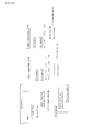
- FIG. 1 is a block diagram illustrating a configuration example of a transmission and reception system according to an embodiment.
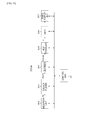
- FIG. 2 is a diagram illustrating an example of a basic stream at 60 Hz that is obtained by performing mixing processing on moving image data at 120 Hz, and an extended stream at +60 Hz.
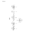
- FIG. 3 is a diagram illustrating an example of a basic stream at 60 Hz that is obtained by performing mixing processing on moving image data at 240 Hz, and an extended stream added thereto.
- FIG. 4 is a diagram illustrating an outline of processing performed by a transmission apparatus and a television receiver.
- FIG. 5 is a diagram schematically illustrating an example of mixing on a transmission side and back mixing on a reception side.
- FIG. 6 is a diagram schematically illustrating another example of the mixing on the transmission side and the back mixing on the reception side.
- FIG. 7 is a block diagram illustrating a configuration example of the transmission apparatus.
- FIG. 8 is a block diagram illustrating a configuration example of a pre-processor that performs the mixing processing on the transmission side.
- FIG. 9 is a block diagram illustrating another configuration example of the pre-processor that performs the mixing processing on the transmission side.
- FIG. 10 is a block diagram illustrating a configuration example of a post-processor that performs back mixing processing on the reception side.
- FIG. 11 is a block diagram illustrating another configuration example of the post-processor that performs back mixing processing on the reception side.
- FIG. 11 is a block diagram illustrating another configuration example of the post-processor that performs back mixing processing on the reception side.
- FIG. 12 is a diagram illustrating a configuration example of ⁇ Blending information SEI message ⁇ .
- FIG. 13 is a diagram illustrating a configuration example of ⁇ Blending_information() ⁇ .
- FIG. 14 is a diagram illustrating main content in the configuration example in ⁇ Blending_information () ⁇ .
- FIG. 15 is a diagram illustrating an example of a change in the information ⁇ Blending_information() ⁇ that is inserted into each frame (picture frame) in moving image data Q at a high frame rate on which mixing processing has been performed.
- FIG. 16 is a diagram illustrating an example of a relation between the mixing processing by the pre-processor and the back mixing processing by the post-processor.
- FIG. 17 is a diagram schematically illustrating an example of the mixing on the transmission side and the back mixing on the reception side.
- FIG. 18 is a diagram illustrating a configuration example of a transport stream TS.
- FIG. 19 is a block diagram illustrating a configuration example of a television receiver that has decoding ability with which moving image data at a high frame rate can be processed.
- FIG. 20 is a block diagram illustrating a configuration example of a television receiver that has decoding ability with which moving image data at a normal frame rate can be processed.
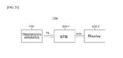
- FIG. 21 is a diagram illustrating another configuration example of the transmission and reception system.
- FIG. 22 is a flowchart illustrating an example of a control processing procedure in a control unit (CPU) in a set top box.
- FIG. 23 is a diagram illustrating an outline of processing performed by the transmission apparatus, the set top box, and a display.
- FIG. 24 is a diagram illustrating a case in which the display has a function of the back mixing processing (mixing release processing) and a case in which the display does not have the function in a compared manner.
- FIG. 25 is a diagram illustrating a configuration example of HFR blending infoframe.
- FIG. 26 is a diagram illustrating content of main information in the configuration example of the HFR blending infoframe.
- FIG. 27 is a diagram illustrating content of main information in the configuration example of the HFR blending infoframe.
- FIG. 28 is a block diagram illustrating a configuration example of the set top box.
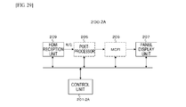
- FIG. 29 is a block diagram illustrating a configuration example of the display that deals with moving image data at a high frame rate.
- FIG. 30 is a block diagram illustrating a configuration example of the display that deals with moving image data at a normal frame rate.
- FIG. 1 illustrates a configuration example of a transmission and reception system 10 according to an embodiment.
- This transmission and reception system 10 has a transmission apparatus 100 and a television receiver 200.
- the transmission apparatus 100 transmits a transport stream TS as a container on a broadcasting wave.
- This transport stream TS includes a basic stream (basic video stream) obtained by processing moving image data at a high frame rate, that is, at 120 Hz or 240 Hz in this embodiment and an extended stream (extended video stream).
- the basic stream and the extended stream have a NAL unit structure.
- the basic stream is obtained as follows. That is, moving image data at a high frame rate after mixing processing is obtained by performing processing of mixing, at a mixing rate independent for each frame, image data in peripheral frames with image data in each frame of the moving image data at the high frame rate before the mixing.
- At least image data in a frame corresponding to the normal frame rate that is, 60 Hz in this embodiment in the image data in each frame that forms the moving image data at the high frame rate after the mixing processing is brought into a state in which the image data is mixed with the image data in the peripheral frames.
- the basic stream is obtained by encoding image data in a frame (basic frame) corresponding to the normal frame rate.
- the extended stream is obtained by encoding image data in the residual frames (extended frames).
- the basic stream includes coded image data in each frame at the normal frame rate as an access unit.
- the extended stream includes a coded image data in each extended frame at the high frame rate as an access unit.
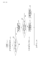
- FIG. 2 illustrates an example of the basic stream at 60Hz that is obtained by performing the mixing processing on moving image data at 120 Hz and an extended stream at +60 Hz.
- a frame pair is formed by one frame that forms the basic stream and one frame corresponding to the following extended frame.
- image data in the frame of the basic stream which is a first frame, is in a state (mixed state) in which the image data is mixed with image data in the peripheral frames while image data in the following frame of the extended stream is in a state (non-mixed state) in which the image data is not mixed with the image data in the peripheral frames, in each frame pair.
- image data in the frame of the basic stream, which is a first frame is in the state (mixed state) in which the image data is mixed with the image data in the peripheral frames while image data in the following frame of the extended stream is also in the state (mixed state) in which the image data is mixed with the image data in the peripheral frames, in each frame pair.
- FIG. 3 illustrate an example of basic streams at 60 Hz that are obtained by performing the mixing processing on moving image data at 240 Hz and an extended stream added thereto.
- a frame pair is formed by four frames including one frame that forms the basic stream and the following three frames corresponding to the extended frames.
- image data in a frame of the basic stream which is a first frame, is in the state (mixed state) in which the image data is mixed with image data in the peripheral frames while image data of all the three following frames of the extended stream is in a state (non-mixed state) in which the image data is not mixed with the image data in the peripheral frames, in each frame pair.
- the image data in the frame of the basic stream which is the first frame, is in the state (mixed state) in which the image data is mixed with the image data in the peripheral frames, in each frame pair.
- image data in a following first frame of the extended stream is in the state (non-mixed state) in which the image data is not mixed with the image data in the peripheral frame
- image data in a second frame is in the state (mixed state) in which the image data is mixed with the image data in the peripheral frames
- image data in a third frame is in the state (non-mixed state) in which the image data is not mixed with the image data in the peripheral frames.
- the image data in the frame of the basic stream which is the first frame, is in the state (mixed state) in which the image data is mixed with the image data in the peripheral frames, in each frame pair.
- image data in a following first frame of the extended stream is in the state (mixed state) in which the image data is mixed with the image data in the peripheral frame
- image data in a second frame is in the state (non-mixed state) in which the image data is not mixed with the image data in the peripheral frames
- image data in a third frame is in the state (mixed state) in which the image data is mixed with the image data in the peripheral frames.
- image data in a frame of the basic stream which is a first frame, is in the state (mixed state) in which the image data is mixed with image data in the peripheral frames while image data of all the three following frames of the extended stream is also in a state (mixed state) in which the image data is mixed with the image data in the peripheral frames, in each frame pair.
- the information about the mixing rate in the corresponding frames is inserted into the basic stream and the extended stream in association with the image data in the respective frames.
- the information about the mixing rate in each frame is respectively a set of coefficients corresponding to the number of taps of a filter used for the mixing processing.
- the coefficient set of each frame includes m coefficients.
- a SEI NAL unit that has the information of the mixing rate (coefficient set) is inserted into the basic stream and the extended stream. The reception side can recognize at which rate the image data in each frame of the basic stream and the extended stream has mixed with peripheral image data, on the basis of the information about the mixing rate.
- the television receiver receives the aforementioned transport stream TS sent on the broadcasting wave from the transmission apparatus 100.
- the reception apparatus 200 processes only the basic stream included in the transport stream TS, obtains the moving image data at the normal frame rate, and reproduces the image.
- the television receiver 200 performs decoding processing on the basic stream and obtains the image data in each frame at the normal frame rate.
- the television receiver 200 processes both the basic stream and the extended stream included in the transport stream TS, obtains the moving image data at the high frame rate, and reproduces the image.
- the television receiver 200 obtains the image data in each frame at the normal frame rate by performing the decoding processing on the basic stream, obtains the image data in each extended frame at the high frame rate by performing the decoding processing on the extended stream, and then performs the back mixing processing by using image data in each frame at the normal frame rate and the image data in each extended frame at the high frame rate on the basis of the information (coefficient set) about the mixing rate in each frame, thereby obtaining the moving image data at the high frame rate that is similar to that before the mixing processing.
- FIG. 4 illustrates an outline of processing performed by the transmission apparatus 100 and the television receiver 200.
- an image sequence Q output from a pre-processor 102 of the transmission apparatus 100 and an image sequence Q output from a decoder 204 of the television receiver 200A are the same in a time series manner, a case in which image quality in both the image sequences Q is different is also included since the image sequences Q are made to pass through a codec.
- Moving image data Va at a higher frame rate that is output from a camera (imaging apparatus) 81 is sent to an HFR processor 82, and moving image data Vb at the high frame rate (120 Hz or 240 Hz) is obtained. This moving image data Vb is input as moving image data P to the transmission apparatus 100.
- the mixing processing is performed on the image data in each frame that forms the moving image data P by the pre-processor 102, and moving image data Q after the mixing processing that includes image data Qb in each frame at the normal frame rate and image data Qe in each extended frame at the high frame rate is obtained.
- an encoder 103 performs encoding processing on the image data Qb and Qe, and a basic stream STb and an extended stream STe are obtained.
- the transmission apparatus 100 transmits these streams STb and STe to the television receiver 200.
- the information about the mixing rate in the corresponding frames is inserted into these streams STb and STe in association with the image data in the respective frames.
- the decoder 204 performs decoding processing on the two streams STb and STe, and the moving image data Q, which includes the image data Qb in each frame at the normal frame rate and the image data Qe in each extended frame at the high frame rate, and on which the mixing processing has been performed, is obtained.
- the post-processor 205 performs the back mixing processing (mixing release processing) on the image data in each frame of the moving image data Q on the basis of the information about the mixing rate in each frame, and moving image data R at the high frame rate (120 Hz or 240 Hz) that is similar to the moving image data P on the transmission side is obtained.
- the moving image data R is used as moving image data for display without any processing performed thereon or by performing frame interpolation by a motion compensated frame insertion (MCFI) unit 206 to increase the frame rate.
- MCFI motion compensated frame insertion
- a decoder 204B performs the decoding processing on the stream STb, and the image data Qb in each frame at the normal frame rate is obtained. Then, in the reception apparatus 200B, the moving image data including the image data Qb in each frame at the normal frame rate is used as moving image data for display without any processing performed or by performing frame interpolation by a motion compensated frame insertion (MCFI) unit 206B to increase the frame rate.
- MCFI motion compensated frame insertion
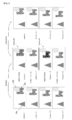
- FIG. 5 schematically illustrating an example of mixing (blending) on the transmission side and back mixing (unblending) on the reception side.
- This example corresponds to the example in (a) in FIG. 2, a frame ⁇ n ⁇ and a frame ⁇ n + 1 ⁇ form a frame pair, and a frame ⁇ n + 2 ⁇ and a frame ⁇ n + 3 ⁇ form a frame pair.
- objects Oa and Ob are objects with no motion while an object Oc is an object with motion in the example illustrated in the drawing.
- the image data in the frame of the basic stream which is the first frame, is brought into a state (mixed state) in which the image data is mixed with image data in the peripheral frames, and image data in the following frame in the extended stream is brought into a state (non-mixed state) in which the image data is not mixed with the image data in the peripheral frames in each frame pair by the mixing processing on the transmission side.
- the mixed state is released by the back mixing processing on the reception side.
- FIG. 6 schematically illustrates another example of the mixing (blending) on the transmission side and the back mixing (unblending) on the reception side.
- This example corresponds to the example in (a) in FIG. 3, and a frame ⁇ n ⁇ and frames ⁇ n + 1 ⁇ to ⁇ n + 3 ⁇ form frame pairs.
- objects Oa and Ob are objects with no motion while an object Oc is an object with motion in the example illustrated in the drawing.
- the image data in the frame of the basic stream which is the first frame, is brought into a state (mixed state) in which the image data is mixed with image data in the peripheral frames, and image data in the following three frames in the extended stream is brought into a state (non-mixed state) in which the image data is not mixed with the image data in the peripheral frames in each frame pair by the mixing processing on the transmission side.
- the mixed state is released by the back mixing processing on the reception side.
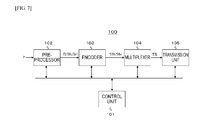
- FIG. 7 illustrates a configuration example of the transmission apparatus 100.
- This transmission apparatus 100 has a control unit 101, the pre-processor 102, the encoder 103, a multiplexer 104, and a transmission unit 105.
- the control unit 101 controls operations of the respective parts in the transmission apparatus 100.
- the pre-processor 102 inputs the moving image data P at the high frame rate (120 Hz or 240 Hz) and outputs the image data Qb in each frame at the normal frame rate (60 Hz) and the image data Qe in each extended frame at the high frame rate.
- the pre-processor performs the processing of mixing, at the mixing rate independent for each frame, the image data in the peripheral frames with the image data in each frame of the moving image data P at the high frame rate before the mixing processing and obtains the moving image data Q at the high frame rate after the mixing processing.
- Image data in each frame corresponding to the normal frame rate (60 Hz) in the moving image data Q is the image data Qb
- image data in each residual frame is the image data Qe.
- at least the image data Qb is in a state in which the image data Qb is mixed with the image data in the peripheral frames.
- the pre-processor 102 includes a filter in a time direction that has two or more taps, for example, and can perform the processing of mixing the image data in the peripheral frames at the mixing rate independent for each frame by changing the coefficient of each tap for each frame.
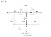
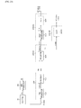
- FIG. 8 illustrates a configuration example of the pre-processor 102.
- This pre-processor 102 includes a filter in the time direction that has three taps.
- This pre-processor 102 has delay elements 102a and 102b that has a delay time of one frame period, coefficient devices 102c, 102d, and 102e, and an adder 102f.
- the moving image data P before the mixing processing is input to a serial circuit of the delay elements 102a and 102b.
- the moving image data P is sent in an order of the delay element 102b and the delay element 102a.
- Image data P1, P2, and P3 in three frames is obtained as three tap outputs on the output side of the delay element 102a, the input side of the delay element 102a (the output side of the delay element 102b), and the input side of the delay element 102b.
- the image data P1, P2, and P3 is multiplied by coefficients a, b, and c by the coefficient devices 102c, 102d, and 102e, respectively.
- the coefficient set (a, b, and c) are switched for each frame.
- the outputs of the respective coefficient devices 102c, 102d, and 102e are added by the adder 102f, and image data Q1, Q2, and Q3 in the respective frames of the moving image data Q after the mixing processing is sequentially obtained from the adder 102f.
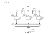
- FIG. 9 illustrates another configuration example of the pre-processor 102.
- This pre-processor 102 includes a filter in the time direction that has three taps.
- This pre-processor 102 is an example in which a coefficient set of a first system, a second system, and a third system is sequentially repeated for each frame.
- This pre-processor 102 has delay elements 102a, 102b that have a delay time of one frame period, coefficient devices 102c1, 102d1, and 102e1 in the first system, coefficient devices 102c2, 102d2, and 102e2 in the second system, a coefficient devices 102c3, 102d3, and 102e3 in the second system, an adder 102f1 in the first system, an adder 102f2 in the second system, an adder 102f3 in the third system, and a frame output switching device (SW) 102g.
- SW frame output switching device
- the moving image data P before the mixing processing is input to a serial circuit of the delay elements 102a and 102b.
- the moving image data P is sent in the order of the delay element 102b and the delay element 102a.
- Image data P1, P2, and P3 in three frames is obtained as three tap outputs on the output side of the delay element 102a, the input side of the delay element 102a (the output side of the delay element 102b), and the input side of the delay element 102b.
- the output of the first system is obtained by multiplying the image data P1, P2, and P3 by coefficients a1, b1, and c1 by the coefficient devices 102c1, 102d1, and 102e1, respectively and then adding the results by the adder 102f1.
- the output of the second system is obtained by multiplying the image data P1, P2, and P3 by coefficients a2, b2, and c2 by the coefficient devices 102c2, 102d2, and 102e2, respectively and then adding the results by the adder 102f2.
- the output of the third system is obtained by multiplying the image data P1, P2, and P3 by coefficients a3, b3, and c3 by the coefficient devices 102c3, 102d3, and 102e3, respectively and then adding the results by the adder 102f3.
- the outputs of the respective systems obtained by the adders 102f1, 102f2, and 102f3 are selectively extracted for each frame by the frame output switching device 102g, and the image data Q1, Q2, and Q3 in the respective frames of the moving image data Q after the mixing processing is sequentially obtained from the frame output switching device 102g.
- the frame output switching device 102g selects a computation result of ⁇ P1*a1 + P2*b1 + P3*c1 ⁇ .
- the frame output switching device 102g selects a computation result of ⁇ P1*a2 + P2*b2 + P3*c2 ⁇ .
- the frame output switching device 102g selects a computation result of ⁇ P1*a3 + P2*b3 + P3*c3 ⁇ .
- the pre-processor 102 sequentially repeats the above processing.
- the pre-processor 102 includes a delay management function such that a synchronization relation between the coefficient set and the corresponding frames does not break.
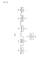
- FIG. 10 illustrates a configuration example of the post-processor 205 that performs the back mixing processing on the reception side.
- This example corresponds to the configuration example of the pre-processor 102 illustrated in FIG. 8.
- This post-processor 205 includes a filter with three taps.
- This post-processor 205 has delay elements 205a and 205b that has a delay time of one frame period, coefficient devices 205c, 205d, and 205e, and an adder 205f.
- the moving image data Q before the back mixing processing is input to a serial circuit of the delay elements 205a and 205b.
- the moving image data Q is sent in the order of the delay element 205b and the delay element 205a.
- Image data Q1, Q2, and Q3 in the three frames is obtained as three tap outputs on the output side of the delay element 205a, the input side of the delay element 205a (the output side of the delay element 205b), and the input side of the delay element 205b.
- the image data Q1, Q2, and Q3 are multiplied by coefficients a', b', and c’ by the coefficient devices 205c, 205d, and 205e, respectively.
- the coefficient set (a', b', and c') is obtained to perform the back mixing processing (mixing release processing) from the coefficient set (a, b, and c) (see FIG. 8) at the time of the mixing processing that is provided from the transmission side and is switched for each frame.
- Outputs of the respective coefficient devices 205c, 205d, and 205e are added by the adder 205f, and image data R1, R2, and R3 in the respective frames of the moving image data R after the back mixing processing is sequentially obtained from the adder 205f.
- FIG. 11 illustrates another configuration example of the post-processor 205 that performs the back mixing processing on the reception side.
- This example corresponds to the configuration example of the pre-processor 102 illustrated in FIG. 9.
- This post-processor 205 includes a filter that has three taps.
- This post-processor 205 is an example in which the coefficient set of the first system, the second system, and the third system is sequentially repeated for each frame.
- This post-processor 205 has delay elements 205a, 205b that have a delay time of one frame period, coefficient devices 205c1, 205d1, and 205e1 in the first system, coefficient devices 205c2, 205d2, and 205e2 in the second system, a coefficient devices 205c3, 205d3, and 205e3 in the second system, an adder 205f1 in the first system, an adder 205f2 in the second system, an adder 205f3 in the third system, and a frame output switching device (SW) 205g.
- SW frame output switching device
- the moving image data P before the back mixing processing is input to a serial circuit of the delay elements 205a and 205b.
- the moving image data Q is sent in the order of the delay element 205b and the delay element 205a.
- Image data Q1, Q2, and Q3 in the three frames is obtained as three tap outputs on the output side of the delay element 205a, the input side of the delay element 205a (the output side of the delay element 205b), and the input side of the delay element 205b.
- the output of the first system is obtained by multiplying the image data Q1, Q2, and Q3 by coefficients a1, b1, and c1 by the coefficient devices 205c1, 205d1, and 205e1, respectively and then adding the results by the adder 205f1.
- the output of the second system is obtained by multiplying the image data Q1, Q2, and Q3 by coefficients a2, b2, and c2 by the coefficient devices 205c2, 205d2, and 205e2, respectively and then adding the results by the adder 205f2.
- the output of the third system is obtained by multiplying the image data Q1, Q2, and Q3 by coefficients a3, b3, and c3 by the coefficient devices 205c3, 205d3, and 205e3, respectively and then adding the results by the adder 205f3.
- the coefficient sets (a1', b1', and c1'), (a2', b2', and c2'), and (a3', b3', c3') are obtained to perform the back mixing processing (mixing release processing) from the coefficient sets (a1, b1, and c1), (a2, b2, and c2), and (a3, b3, and c3) (see FIG. 9) at the time of the mixing processing that are provided from the transmission side.
- the outputs of the respective systems obtained by the adders 205f1, 205f2, and 205f3 are selectively extracted for each frame by the frame output switching device 205g, and the image data R1, R2, and R3 in the respective frames of the moving image data R after the mixing processing is sequentially obtained from the frame output switching device 205g.
- the frame output switching device 205g selects a computation result of ⁇ Q1*a1' + Q2*b1' + Q3*c1' ⁇ .
- the frame output switching device 205g selects a computation result of ⁇ Q1*a2' + Q2*b2' + Q3*c2' ⁇ .
- the frame output switching device 205g selects a computation result of ⁇ Q1*a3' + Q2*b3' + Q3*c3' ⁇ .
- the post-processor 205 sequentially repeats the above processing for each frame.
- the post-processor 205 includes the delay management function such that the synchronization relation between the coefficient sets and the corresponding frames does not break.
- the encoder 103 performs encoding processing on the image data Qb and Qe that is obtained by the pre-processor 102 and generates the basic stream STb and the extended stream STe.
- prediction encoding processing such as H.264/AVC or H.265/HEVC, for example is performed on the image data Qb and Qe.
- the encoder 102 inserts the information about the mixing rate in the corresponding frames into the basic stream STb and the extended stream STe in association with the image data in the respective frames.
- the reception side can recognize at which rate the image data in each frame of the basic stream and the extended stream has been mixed with peripheral image data, on the basis of the information about the mixing rate and can appropriately perform the back mixing processing (mixing release processing).
- a SEI NAL unit that has information about the mixing rate is inserted into the respective access units of the basic stream STb and the extended stream STe.
- the encoder 103 inserts a blending information SEI message for new definition into a portion of "SEIs" in the access unit (AU).
- FIG. 12 illustrates a structure example (Syntax) of ⁇ Blending_information SEI message ⁇ .
- ⁇ uuid_iso_iec_11578 ⁇ has a UUID value indicated by "ISO/IEC 11578:1996 AnnexA".
- ⁇ is inserted into the field of ⁇ user_data_payload_byte ⁇ .
- (b) in FIG. 12 illustrates a configuration example (Syntax) of ⁇ Blending_information_SEI() ⁇ , and ⁇ Blending_information () ⁇ including the information about the mixing rate is inserted therein.
- ⁇ userdata_id ⁇ is an identifier indicated by 16 bits with no codes. 8-bit field of ⁇ Blending_information_SEI_length ⁇ indicates a byte size of ⁇ Blending_information_SEI_length ⁇ at and after the field.
- FIG. 13 illustrates a structure example (Syntax) of ⁇ Blending_information() ⁇
- FIG. 14 illustrates content (Semantics) of main information in the structure example.
- 3-bit field ⁇ frame_rate ⁇ represents a frame rate. For example, "3" represents 120 Hz, and "5" represents 240 Hz.
- 1-bit field of ⁇ blending_flag ⁇ represents whether or not the mixing processing with the peripheral image data is to be applied. For example, “0" represents that no application is to be made, and “1" represents that application is to be made.
- 2-bit field of ⁇ temporal_filter_taps ⁇ is configuration information of the filter used for performing the mixing processing and represents the number of frames used (the number of taps). For example, “0” represents two frames (two taps), and "1" represents three frames (three taps).
- 1-bit field of ⁇ first_frame_in_frame-pair_flag ⁇ indicates whether the frame is the first frame of the frame pair, that is, whether the frame is a frame corresponding to the temporal display position at the normal frame rate. For example, "0" represents that the frame is a frame other than the first frame, and "1" represents that the frame is the first frame.
- the frame pair includes the one frame that forms the basic stream and the following predetermined number of extended frames as described above (see FIGS. 2 and 3).
- 3-bit field of ⁇ blending_refresh_distance (BR distance) ⁇ represents the number of frames (temporal distance) until temporal linkage of the mixing processing is refreshed without using the image data in the temporarily previous frame. For example, “0" represents one frame, “1” represents two frames, and “2" represents three frames.
- 1-bit field of ⁇ refresh_flag ⁇ indicates whether or not the frame refreshes the aforementioned temporal linkage of the mixing processing. For example, "0" represents that the mixing refresh is not performed for the frame, and "1" represents that the mixing refresh is performed for the frame.
- 8-bit field of ⁇ blend_coefficient ⁇ is repeatedly present to correspond to the number of frames (the number of taps) represented by the aforementioned field of ⁇ temporal_filter_taps ⁇ .
- This field represents a coefficient (blend ratio) by which the image data in each frame is multiplied. For example, “0 x 0" represents ⁇ 0 ⁇ , “0 x 1" represents ⁇ 1/5 ⁇ , “0 x 2" represents ⁇ 1/4 ⁇ , "0 x 3" represents ⁇ 1/3 ⁇ , "0 x 4" represents ⁇ 1/2 ⁇ , “0 x 5" represents ⁇ 2/3 ⁇ , “0 x 6" represents ⁇ 3/4 ⁇ , “0 x 7" represents ⁇ 4/5 ⁇ , and "0 x 8" represents ⁇ 1 ⁇ .
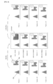
- FIG. 15 illustrates an example of a change in the information of ⁇ Blending_information() ⁇ to be inserted into each frame (picture frame) in the moving image data Q at the high frame rate, on which the mixing processing has been performed.
- the example illustrated in the drawing illustrates a case in which ⁇ temporal_filter_taps ⁇ is "1" and the number of frames (the number of taps) is ⁇ 3 ⁇ .
- the frame ⁇ n ⁇ included in the basic stream represents that ⁇ refresh_flag ⁇ is "1" and the mixing refresh is to be performed for the frame, and also ⁇ bleding_refresh_distance (BR distance) ⁇ is "3" and the number of frames until the frame for which the next mixing refresh is to be performed is four frames.
- BR distance ⁇ bleding_refresh_distance
- the frame ⁇ n + 1 ⁇ included in the extended frame represents that ⁇ refresh_flag ⁇ is "0" and the mixing refresh is not to be performed for the frame, and also ⁇ blending_refresh_distance (BR distance) ⁇ is "2" and the number of frames until the frame for which the next mixing fresh is performed is three frames.
- BR distance ⁇ blending_refresh_distance
- the frame ⁇ n + 2 ⁇ included in the basic frame represents that ⁇ refresh_flag ⁇ is "0" and the mixing fresh is not to be performed for the frame, and also ⁇ blending_refresh_distance (BR distance) ⁇ is "1" and the number of frames until the frame for which the next mixing refresh is performed is two frames.
- BR distance ⁇ blending_refresh_distance
- the frame ⁇ n + 3 ⁇ included in the extended frame represents that ⁇ refresh_flag ⁇ is "0" and the mixing refresh is not to be performed for the frame, and also ⁇ blending_refresh_distance (BR distance) ⁇ is "0" and the number of frames until the frame for which the next mixing fresh is performed is one frame.
- BR distance ⁇ blending_refresh_distance
- the frame ⁇ n + 4 ⁇ included in the basic stream represents that ⁇ refresh_flag ⁇ is "1" and the mixing refresh is to be performed for the frame, and also ⁇ bleding_refresh_distance (BR distance) ⁇ is "3" and the number of frames until the frame for which the next mixing refresh is to be performed is four frames.
- BR distance ⁇ bleding_refresh_distance
- FIG. 16 corresponds to the example in FIG. 15 and illustrates an example of a relation between the mixing processing performed by the pre-processor 102 and the back mixing processing performed by the post-processor 205.
- the coefficient (mixing ratio) used in the back mixing processing performed by the post-processor 205 is obtained on the basis of a coefficient (mixing ratio) used in the latest processing.
- the post-processor 205 performs the back mixing processing from the frame with ⁇ refresh_flag ⁇ of "1".
- the back mixing processing is performed from the previous frame of the frame with ⁇ refresh_flag ⁇ of "1", that is, in the order of the frame ⁇ n + 2 ⁇ , the frame ⁇ n + 1 ⁇ , and the frame ⁇ n ⁇ while tracking back from the frame ⁇ n + 3 ⁇ in FIG.
- FIG. 17 schematically illustrates an example of the mixing (blending) on the transmission side and the back mixing (unblending) on the reception side.
- the multiplexer 104 packetized-elementary-stream (PES) packetizes the basic stream STb and the extended stream STe that are generated by the encode 103 and further transport-packetizes and multiplexes the streams, thereby obtaining the transport stream TS as a multiplexed stream.
- PES packetized-elementary-stream
- FIG. 18 illustrates a configuration example of the transport stream TS.
- This transport stream TS includes two video streams, namely the basic stream (base stream) STb and the extended stream (enhanced stream) STe. That is, a PES packet ⁇ video PES1 ⁇ of the basic stream STb is present, and also a PES packet ⁇ video PES2 ⁇ of the extended stream STe is present in this configuration example.
- the blending information SEI message (see FIG. 13) is inserted into encoded image data of each picture that forms a container of the PES packet ⁇ video PES1 ⁇ and the PES packet ⁇ video PES2 ⁇ .
- the transport stream TS includes a program map table (PMT) as one piece of program specific information (PSI).
- the PSI is information describing which programs the respective elementary streams included in the transport stream belong to.
- a program loop that describes information related to the entire programs is present in the PMT.
- an elementary stream loop that has information related to the respective video streams is present in the PMT.
- a video elementary stream loop ⁇ video ES1 loop ⁇ corresponding to the basic stream is present, and a video elementary stream loop ⁇ video ES2 loop ⁇ corresponding to the extended stream is present.
- Information such as a stream type and a packet identifier (PID) is arranged to correspond to the basic stream (video PES1), and also a descriptor that describes the information related to the video stream is also arranged in ⁇ video ES1 loop ⁇ .
- This stream type is "0 x 24" indicating the basic stream in a case of HEVC coding.
- information such as a stream type and a packet identifier (PID) is arranged to correspond to the extended stream (video PES2), and also, a descriptor that describes the information related to the video stream is also arranged in ⁇ video ES2 loop ⁇ .
- This stream type is "0 x 25" indicating the extended stream.
- the transmission unit 105 modulates the transport stream TS by a modulation scheme that is suitable for broadcasting, such as QPSK/OFDM, and transmits an RF modulation signal to a transmission antenna.
- a modulation scheme that is suitable for broadcasting, such as QPSK/OFDM
- Moving image data P at the high frame rate (120 Hz or 240 Hz) is input to the pre-processor 102.
- the mixing processing is performed on the moving image data P, and the image data Qb in each frame at the normal frame rate (60 Hz) and the image data Qe in each extended frame at the high frame rate are obtained.
- this moving image data Q image data in each frame corresponding to the normal frame rate (60 Hz) is regarded as the image data Qb, and image data in the residual respective frames is regarded as the image data Qe.
- at least the image data Qb is brought into a state in which the image data Qb is mixed with the image data in the peripheral frames.
- the image data Qb and Qe obtained by the pre-processor 102 is supplied to the encoder 103.
- the encoder 103 encoding processing is performed on the image data Qb and Qe, and the basic stream STb and the extended stream STe are generated.
- the information about the mixing ratio in the mixing processing is inserted onto the basic stream STb and the extended stream STe.
- the encoder 103 inserts the information about the mixing rate in the corresponding frames into the basic stream STb and the extended stream STe in association with the image data in the respective frames.
- the reception side can recognize at which rate the image data in each frame of the basic stream and the extended stream has been mixed with peripheral image data, on the basis of the information about the mixing rate and can appropriately perform the back mixing processing (mixing release processing).
- the basic stream STb and the extended stream STe generated by the encoder 103 is supplied to the multiplexer 104.
- the multiplexer 104 PES packetizes the basic stream STb and the extended stream STe and further transport-packetizes and multiplexes the streams, thereby obtaining the transport stream TS as a multiplexed stream.
- the transport stream TS generated by the multiplexer 104 is sent to the transmission unit 105.
- the transmission unit 105 modulates this transport stream TS by a modulation scheme that is suitable for broadcasting, such as QPSK/OFDM, for example, and transmits an RF modulation signal from the transmission antenna.
- FIG. 19 illustrates a configuration example of the television receiver 200A that has decoding ability with which moving image data at the high frame rate (120 Hz or 240 Hz) can be processed.
- This television receiver 200A has a control unit 201, a reception unit 202, a demultiplexer 203, a decoder 204, the post-processor 205, a motion compensated frame insertion (MCFI) unit 206, and a panel display unit 207.
- MCFI motion compensated frame insertion
- the control unit 201 controls operations of the respective parts in the television receiver 200A.
- the reception unit 202 demodulates the RF modulation signal received by a reception antenna and acquires the transport stream TS.
- the demultiplexer 203 extracts the basic stream STb and the extended stream STe by PID filtering from the transport stream TS and supplies the basic stream STb and the extended stream STe to the decoder 204.
- the decoder 204 performs decoding processing on the basic stream STb to obtain the image data Qb in each frame at the normal frame rate and performs decoding processing on the extended stream STe to obtain the image data Qe in each extended frame at the high frame rate. In this manner, the moving image data Q at the high frame rate, on which the mixing processing of the image data Qb and the image data Qe has been performed, is obtained.
- the decoder 204 extracts a parameter set and SEI that have been inserted into the respective access units that form the basic stream STb and the extended stream STe and sends the parameter set and the SEI to the control unit 201.
- the blending information SEI (see FIG. 13) that has information about the mixing rate is extracted.
- the control unit 201 can recognize at which rate the image data in each frame of the moving image data Q at the high frame rate after the mixing processing has been mixed with the peripheral image data, obtain coefficients for the back mixing processing, and satisfactorily control the post-processor 205, which will be described later.
- the post-processor 205 performs the back mixing processing (mixing release processing) on the moving image data Q at the high frame rate, which has been obtained by the decoder 204, under the control by the control unit 201 and obtains mixing-released moving image data R at the high frame rate.
- the post-processor 205 includes a filter that has two or more taps, for example, and can release the mixing by changing the coefficient of each tap for each frame and mixing the image data in the peripheral frames at the mixing rate independent for each frame (see FIGS. 10, 11, and 16).
- the control unit 201 calculates the coefficient set for each frame on the basis of the coefficient set at the time of the mixing processing, which has been inserted into each frame of the moving image data Q, and uses the coefficient set as described above.
- the MCFI unit 206 performs frame interpolation processing of motion compensation on the moving image data R at the high frame rate, which has been obtained by the post-processor 205, and obtains the moving image data at a further increased frame rate. In addition, there is also a case in which this MCFI unit 206 is not provided.
- the panel display unit 207 performs image display based on the moving image data R at the high frame rate that has been obtained by the post-processor 205 or the moving image data at a frame rate increased by the MCFI unit 206.
- the reception unit 202 demodulates the RF modulation signal received by the reception antenna and acquires the transport stream TS.
- This transport stream TS is sent to the demultiplexer 203.
- the demultiplexer 203 extracts the basic stream STb and the extended stream STe from the transport stream TS by the PID filtering and supplies the basic stream STb and the extended stream STe to the decoder 204.
- the decoder 204 performs the decoding processing on the basic stream STb and the extended stream STe and obtains the moving image data Q at the high frame rate after the mixing processing that includes the image data Qb in each frame at the normal frame rate and the image data Qe in each extended frame at the high frame rate.
- the moving image data Q is supplied to the post-processor 205.
- the decoder 204 extracts a parameter set and SEI inserted into each access unit that forms the basic stream STb and the extended stream STe and sends the parameter set and the SEI to the control unit 201.
- the blending information SEI (see FIG. 13) that has information about the mixing rate is also extracted.
- the control unit 201 computes the coefficients for the back mixing processing on the basis of the information about the mixing rate (coefficient set) in each frame.
- the post-processor 205 performs the back mixing processing (mixing release processing) on the moving image data Q at the high frame rate under control by the control unit 201 and obtains the mixing-released moving image data R at the high frame rate.
- the coefficients for the back mixing processing are provided from the control unit 201 to the post-processor 205.
- the mixing-released moving image data R at the high frame rate that has been obtained by the host processor 205 or the moving image data at the frame rate further increased by the MCFI unit 206 is supplied to the panel display unit 207, and the panel display unit 207 performs image display based on the moving image data.
- FIG. 20 illustrates a configuration example of a television receiver 208B that has decoding ability with which the moving image data at the normal frame rate (60 Hz) can be processed.
- This television receiver 200B has a control unit 201B, a reception unit 202B, a demultiplexer 203B, a decoder 204B, an MCFI unit 206B, and a panel display unit 207B.
- the control unit 201B controls operations of the respective parts in the television receiver 200B.
- the receiver unit 202B demodulates the RF modulation signal received by the reception antenna and acquires the transport stream TS.
- the demultiplexer 203B extracts the basic stream STb from the transport stream Ts by the PID filtering and supplies the basic stream STb to the decoder 204B.
- the decoder 204B performs the decoding processing on the basic stream STb and obtains the moving image data at the normal frame rate that includes the image data Qb in each frame at the normal frame rate.
- the MCFI unit 206B performs frame interpolation processing of motion compensation on the moving image data at this normal frame rate and obtains the moving image data at a further increased frame rate. In addition, there is also a case in which this MCFI unit 206 is not provided.
- the panel display unit 207B performs image display based on the moving image data R at the normal frame rate that has been obtained by the post-processor 205 or the moving image data at a frame rate increased by the MCFI unit 206.
- the reception unit 202B demodulates the RF modulation signal received by the reception antenna and acquires the transport stream TS.
- This transport stream TS is sent to the demultiplexer 203B.
- the demultiplexer 203B extracts the basic stream STb from the transport stream TS by the PID filtering and supplies the basic stream STb to the decoder 204.
- the decoder 204B performs the decoding processing on the basic stream STb and obtains the moving image data at the normal frame rate that includes the image data Qb in each frame at the normal frame rate.
- the moving image data at the normal frame rate obtained by the decoder 204B or the moving image data at the frame rate further increased by the MCFI unit 206B is supplied to the panel display unit t207B, and the panel display unit 207B performs image display based on the moving image data.
- At least the image data in the frame corresponding to the normal frame rate in the image data in each frame that forms the moving image data at the high frame rate is mixed with the image data in the peripheral frames and is brought into a state in which the shutter aperture ratio is increased, and basic stream STb obtained by encoding the image data in the frame corresponding to the normal frame rate is transmitted in the transmission and reception system 10 illustrated in FIG. 1.
- the extended stream STe obtained by encoding the image data in the residual frames is obtained along with the basic stream STb, in the transmission and reception system 10 illustrated in FIG. 1, and the information (coefficient set) about the mixing rate in the corresponding frames is inserted into the basic stream STb and the extended stream STe in association with the image data in the respective frames and is then transmitted. Therefore, in a case of a receiver that has decoding ability with which the moving image data at the high frame rate can be processed, it is possible to easily obtain the mixing-released moving image data at the high frame rate on the basis of the information about the mixing rate in each frame and to satisfactorily display the moving image at the high frame rate.
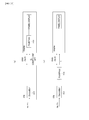
- FIG. 21 illustrates a configuration example of a transmission and reception system 10A.
- This transmission and reception system 10A has a configuration having the transmission apparatus 100, a set top box (STB) 200-1, and a display 200-2.
- the set top box (STB) 200-1 and the display 200-2 are connected by the HDMI.
- a set top box 200-1 receives the transport stream TS sent on the broadcasting wave from the transmission apparatus 100.
- the set top box 200-1 processes both the basic stream STb and the extended stream STe included in the transport stream TS and obtains the moving image data Q at the high frame rate, on which the mixing processing has been performed.
- the set top box 200-1 sends the moving image data Q at the high frame rate, on which the mixing processing has been performed, and the information (coefficient set) about the mixing rate in each frame to the display 200-2 via the HDMI transfer path.
- the set top box 200-1 performs the back mixing processing (mixing release processing) on the moving image data Q at the high frame rate, on which the mixing processing has been performed, on the basis of the information (coefficient set) about the mixing rate in each frame and obtains the mixing-released moving image data R at the high frame rate. Then, the set top box 200-1 sends the moving image data R at the high frame rate to the display 200-2 via the HDMI transfer path.
- the set top box 200-1 processes only the basic stream STb included in the transport stream TS and obtains the moving image data at the normal frame rate that includes the image data Qb in each frame at the normal frame rate. Then, the set top box 200-1 sends the moving image data at the normal frame rate to the display 200-2 via the HDMI transfer path.
- the set top box 200-1 that serves as a source device acquires EDID from the display 200-2 that serves as a sink device, determines whether or not the display 200-2 can deal with the moving image data at the high frame rate (120 Hz or 240 Hz), and further determines whether or not the display 200-2 has the function of the back mixing processing (mixing release processing).
- the flowchart in FIG. 22 illustrates an example of a control processing procedure in a control unit (CPU) of the set top box 200-1.
- the control unit starts control processing in Step ST1.
- the control unit reads and checks EDID from the display 200-2 in Step ST2.
- the control unit determines whether or not the display 200-2 can deal with the moving image data at the high frame rate (120 Hz or 240 Hz) in Step ST3.
- control unit decodes only the basic stream STb and transmits the moving image data at the normal frame rate that includes the image data Qb in each frame at the normal frame rate to the set top box 200-1 in Step ST4.
- the control unit completes the control processing in Step ST5 after this processing in Step ST4.
- control unit decodes the basic stream STb and the extended stream STe in Step ST6.
- control unit determines whether or not the display 200-2 has the function of the back mixing processing (mixing release processing) in Step ST7.
- the control unit decides that the back mixing processing is performed on the side of the set top box 200-1 and transmits the mixing-released moving image data R at the high frame rate to the set top box 200-1 in Step ST8.
- the control unit completes the control processing in Step ST5 after this processing in Step ST8.
- the control unit decides that the back mixing processing is performed on the side of the display 200-2 and sends the moving image data Q at the high frame rate, on which the mixing processing has been performed, and the information (coefficient set) about the mixing rate in each frame to the display 200-2 via the HDMI transfer path in Step ST9.
- the control unit completes the control processing in Step ST5 after this processing in Step ST9.
- FIG. 23 illustrates an outline of processing performed by the transmission apparatus 100, the set top box 200-1, and the display 200-2.
- the image sequence Q output from the pre-processor 102 of the transmission apparatus 100 and the image sequence Q output from the decoder 204 of the set top box 200-1 are the same in the time-series manner, a case in which image quality is different in both the image sequences Q is also included since the image sequences Q are made to pass through a codec. Since the transmission apparatus is similar to that described above in FIG. 4, the description thereof will be omitted here.
- the decoder 204 performs the decoding processing on the two streams STb and STe and obtains the moving image data Q, which includes the image data Qb in each frame at the normal frame rate and the image data Qe in each extended frame at the high frame rate, on which the mixing processing has been performed.
- the set top box 200-1 transmits the moving image data Q and the information (coefficient set) about the mixing rate in each frame to the display 200-2A via the HDMI transfer path.
- the example illustrated in the drawing illustrates a case in which the display 200-2A includes the post-processor 205 and the display 200-2A has the function of the back mixing processing (mixing release processing).
- (a) in FIG. 24 illustrates a state in this case.
- the set top box 200-1 performs the back mixing processing (mixing release processing) on the moving image data Q by the post-processor 200-5 that the set top box 200-1 itself has and obtains the mixing-released moving image data R at the high frame rate. Then, the set top box 200-1 transmits this moving image data R to the display 200-2A via the HDMI transfer path.
- FIG. 24 illustrates a state in this case.
- the decoder 204 performs the decoding processing on the stream ST and obtains the moving image data at the normal frame rate that includes the image data Qb in each frame at the normal frame rate. Then, the set top box 200-1 transmits the moving image data to the display 200-2B via the HDMI transfer path.
- the set top box 200-1 transmits the moving image data Q, on which the mixing processing has been performed, and the information (coefficient set) about the mixing rate in each frame to the display 200-2A that can deal with the moving image data at the high frame rate (120 Hz or 240 Hz) and has the function of the back mixing processing (mixing release processing) via the HDMI transfer path as described above.
- the information (coefficient set) about the mixing rate is inserted into and transmitted with the blanking period of the moving image data Q, for example.
- an HFR blending infoframe newly defined is used.
- FIG. 25 illustrates a structure example (syntax) of the HFR blending infoframe
- FIGS. 26 and 27 illustrate content (semantics) of main information in the structure example.
- the first 3 bytes of this infoframe correspond to a header portion, and information about an infoframe type, a version number, a byte length of data byte is arranged therein.
- 3-bit information of ⁇ frame_rate ⁇ is arranged from the seventh to fifth bits of data byte 1 (Date Byte 1).
- the 3-bit information represents a frame rate. For example, “3” represents 120 Hz, and "5" represents 240 Hz.
- 1-bit information of ⁇ blending_flag ⁇ is arranged at the fourth bit of the data byte 1 (Date Byte 1).
- the 1-bit information represents whether or not the mixing processing with the peripheral image data is to be applied. For example, “0" represents the mixing processing is not to be applied, and "1" represents the mixing processing is to be applied.
- 2-bit information of ⁇ temporal_filter_taps ⁇ is arranged from the third to second bits of the data byte 1 (Date Byte 1).
- This 2-bit information is configuration information of the filter used for performing the mixing processing and represents the number of frames used (the number of taps). For example, "0" represents two frames (two taps), and "1" represents three frames (three taps).
- 1-bit information of ⁇ first_frame_in_frame-pair_flag (FF) ⁇ is arranged at the first bit of the data byte 1 (Date Byte1).
- This 1-bit information represents whether or not the frame is the first frame of the frame pair (frame-pair), that is, whether or not the frame corresponds to the normal frame rate). For example, "0" represents that the frame is a frame other than the first frame, and "1" represents that the frame is the first frame.
- 1-bit information of ⁇ Synchronized Frame (SF) ⁇ is arranged at the 0-th bit of the data byte 1 (Date Byte 1).
- This 1-bit information represents whether or not it is necessary to perform synchronization processing with the next video frame. For example, “0” represents that it is not necessary to perform the synchronization processing with the next video frame, and "1" represents that it is necessary to perform the synchronization processing with the next video frame.
- 3-bit information of ⁇ blending_refresh_distance (BR distance) ⁇ is arranged from the seventh to fifth bits of data byte 2 (Date Byte 2).
- This 3-bit information represents the number of frames (temporal distance) until the temporal linkage of the mixing processing is refreshed without using image data in a temporarily previous frame. For example, "0" represents one frame, "1" represents two frames, and "2" represents three frames.
- 1-bit information of ⁇ refresh_flag ⁇ is arranged at the fourth bit of the data byte 2 (Date Byte 2).
- This 1-bit information represents whether or not the frame is a frame for which the aforementioned temporal linkage of the mixing processing is refreshed. For example, “0" represents that the frame is a frame for which the mixing refresh is not performed, and “1" represents that the frame is a frame for which the mixing refresh is performed.
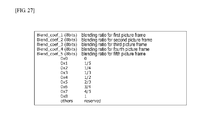
- blending ratios (coefficients) for the first to fifth picture frames are arranged from data byte 3 (Date Byte 3) to data byte 7 (Date Byte 7).
- the blending ratios correspond to the number of frames (the number of taps) represented by a field of ⁇ temporal_filter_taps ⁇ .
- 0 x 0 represents ⁇ 0 ⁇
- 0 x 1 represents ⁇ 1/5 ⁇
- 0 x 2 represents ⁇ 1/4 ⁇
- 0 x 3 represents ⁇ 1/3 ⁇
- 0 x 4" represents ⁇ 1/2 ⁇
- 0 x 5" represents ⁇ 2/3 ⁇
- 0 x 6 represents ⁇ 3/4 ⁇
- 0 x 7 represents ⁇ 4/5 ⁇
- 0 x 8 represents ⁇ 1 ⁇ .
- information included in the blending information SEI message is used without any processing performed thereon as information other than Synchronized Frame, that is, information of ⁇ frame_rate ⁇ , ⁇ blending_flag ⁇ , ⁇ temporal_filter_taps ⁇ , ⁇ first_frame_in_frame-pair_flag ⁇ , ⁇ blending_refresh_distance (BR distance) ⁇ , and ⁇ refresh_flag ⁇ to be included in the HFR blending infoframe.
- FIG. 28 illustrates a configuration example of the set top box 200-1.
- This set top box 200-1 has a control unit 201-1, the reception unit 202, the demultiplexer 203, the decoder 204, the post-processor 205, and an HDMI transmission unit 208.
- the control unit 201-1 controls operations of the respective parts in the set top box 200-1.
- the reception unit 202 demodulates the RF modulation signal received by the reception antenna, acquires the transport stream TS, and sends the transport stream TS to the demultiplexer 203.
- the demultiplexer 203 extracts both the basic stream STb and the extended stream STe or extracts the basic stream STb by the PID filtering depending on whether or not the display 200-2 can deal with the moving image data at the high frame rate (120 Hz or 240 Hz).
- the decoder 204 When the demultiplexer 203 extracts the basic stream STb and the extended stream STe, the decoder 204 performs the decoding processing on the basic stream STb to obtain the image data Qb in each frame at the normal frame rate and performs the decoding processing on the extended stream STe to obtain the image data Qe in each extended frame at the high frame rate. That is, the moving image data Q at the high frame rate, on which the mixing processing of the image data Qb and the image data Qe has been performed, is obtained.
- the decoder 204 extracts the parameter set and the SEI that have been inserted into each access unit that forms the basic stream STb and the extended stream STe and sends the parameter set and the SEI to the control unit 201-1.
- the blending information SEI (see FIG. 13) that has the information about the mixing rate is also extracted.
- control unit 201-1 can recognize at which rate the image data in each frame of the moving image data Q at the high frame rate after the mixing processing has been mixed with the peripheral image data, obtain the coefficients for the back mixing processing, and satisfactorily control the post-processor 205, which will be described later.
- control unit 201-1 can obtain various kinds of information arranged in the HFR blending infoframe from the blending information SEIL when the HFR blending infoframe is transmitted to the display 200-2.
- the demultiplexer 203 extracts only the basic stream STb, the decoding processing is performed on the basic stream STb, and the moving image data at the normal frame rate that includes the image data Qb in each frame at the normal frame rate is obtained.
- the post-processor 205 performs the back mixing processing (mixing release processing) on the moving image data Q at the high frame rate that has been obtained by the decoder 204 and obtains the mixing-released moving image data R at the high frame rate.
- the HDMI transmission unit 208 transmits non-compressed moving image data to the display 200-2 via the HDMI transfer path through communication in accordance with the HDMI.
- the display 200-2 can deal with the moving image data at the high frame rate and does not have the function of the back mixing processing
- the mixing-released moving image data R at the high frame rate that has been obtained by the post-processor 205 is transmitted to the display 200-2 via the HDMI transfer path.
- the display 200-2 can deal with the moving image data at the high frame rate and has the function of the back mixing processing
- the moving image data Q at the high frame rate which has been obtained by the decoder 204, on which the mixing processing has been performed, is transmitted to the display 200-2 via the HDMI transfer path.
- the HFR blending infoframe (see FIG. 25) including the information about the mixing rate is inserted into and transmitted with the blanking period of the image data in each frame that forms the moving image data Q.
- the moving image data at the normal frame rate that includes the image data Qb in each frame at the normal frame rate that has been obtained by the decoder 204 is transmitted to the display 200-2 via the HDMI transfer path.
- FIG. 29 illustrates a configuration example of the display 200-2A that deals with the moving image data at the high frame rate.
- the display 200-2A has a control unit 201-2A, an HDMI reception unit 209, the post-processor 205, the MCFI unit 206, and the panel display unit 207.
- the post-processor 205 is not provided.
- the control unit 201-2A controls operations of the respective parts in the display 200-2A.
- the HDMI reception unit 209 receives non-compressed moving image data at the high frame rate from the set top box 200-1 via the HDMI transfer path through the communication in accordance with the HDMI.
- the mixing-released moving image data R at the high frame rate is received.
- the control unit 201-2A can recognize at which rate the image data in each frame of the moving image data Q at the high frame rate after the mixing processing has been mixed with the peripheral image data, obtain the coefficients for the back mixing processing, and satisfactorily control the post-processor 205, which will be described later.
- the post-processor 205 performs the back mixing processing (mixing release processing) on the moving image data Q at the high frame rate, which has been received by the HDMI reception unit 208, and obtains the mixing-released moving image data R at the high frame rate under the control by the control unit 201-2A.
- the MCFI unit 206 performs frame interpolation processing of motion compensation on the moving image data R at the high frame rate, which has been received by the HDMI reception unit 209 or obtained by the post-processor 205, and obtains the moving image data at a further increased frame rate. In addition, there is also a case in which this MCFI unit 206 is not provided.
- the panel display unit 207 performs image display based on the moving image data R at the high frame rate that has been obtained by the post-processor 205 or the moving image data at a frame rate increased by the MCFI unit 206.
- FIG. 30 illustrates a configuration example of the display 200-2B that deals with the moving image data at the normal frame rate.
- This display 200-2B has a control unit 201-2B, an HDMI reception unit 209B, the MCFI unit 206B, and the panel display unit 207B.
- the control unit 201-2B controls operations of the respective parts in the display 200-2B.
- the HDMI reception unit 209B receives non-compressed moving image data at the normal frame rate from the set top box 200-1 via the HDMI transfer path through the communication in accordance with the HDMI.
- the MICFI unit 206B performs the frame interpolation processing of motion compensation on the moving image data at the normal frame rate, which has been received by the HDMI reception unit 209B, and obtains the moving image data at the increased frame rate. In addition, there is also a case in which the MCFI unit 206B is not provided.
- the panel display unit 207B performs image display based on the moving image data at the normal frame rate, which has been received by the HDMI reception unit 209B, or the moving image data at eh frame rate increased by the MCFI unit 206B.
- the display 200-2 can easily obtain the mixing-released moving image data obtained by performing the back mixing processing on the moving image data Q at the high frame rate on the basis of the information about the mixing rate in each frame and can satisfactorily displays a moving image.
- the combination of the frame rates is not limited thereto.
- the same is true to the combination of 100 Hz or 200 Hz and 50 fps.
- the transmission and reception system 100 that includes the transmission apparatus 100 and the television receiver 200 and further the transmission and reception system 10A that includes the transmission apparatus 100, the set top box 200-1, and the display 200-2 have been illustrated in the aforementioned embodiment, the configuration of the transmission and reception system to which the present technology can be applied is not limited thereto.
- the container is the transport stream (MPEG-2 TS)
- MPEG-2 TS transport stream
- the present technology can also similarly be applied to a system with a configuration in which distribution to a reception terminal is performed by using a network such as the Internet.
- distribution is performed by using a container of MP4 or another format in many cases. That is, containers in various formats such as a transport stream (MPEG-2 TS), or mpeg media transport (MMT) that have been employed by digital broadcasting standards and ISOBMFF (MP4) that is used in the Internet distribution can be applied as the container.
- MP4 transport stream
- MP4 ISOBMFF
- a transmission apparatus comprising: circuitry configured to perform processing of mixing, at a mixing rate for each frame, a frame of first video data with one or more peripheral frames of the first video data and obtain second video data at a first frame rate, the second video data including frames corresponding to a second frame rate that is lower than the first frame rate, the frames corresponding to the second frame rate being mixed with the peripheral frames, and the circuitry is further configured to encode the frames corresponding to the second frame rate to obtain a basic stream and encode remaining frames of the second video data to obtain an extended stream, insert information about the mixing rate of corresponding frames into the basic stream and the extended stream in association with the respective frames, and transmit the basic stream and the extended stream into which the information about the mixing rate has been inserted.
- the transmission apparatus according to (1) wherein the basic stream and the extended stream have a Network Abstraction Layer (NAL) unit structure, and the circuitry is configured to insert a Supplemental Enhancement Information (SEI) NAL unit with the information about the mixing rate into the basic stream and the extended stream.
- SEI Supplemental Enhancement Information
- configuration information of a filter used to perform the mixing processing is included in the information about the mixing rate.
- mixing refresh information indicating a number of frames until mixing refresh that does not use a temporally previous frame is performed is included in the information about the mixing rate.
- a transmission method comprising: performing, by circuitry, processing of mixing, at a mixing rate for each frame, a frame of first video data with one or more peripheral frames of the first video data and obtain second video data at the first frame rate, the second video data including frames corresponding to a second frame rate that is lower than the first frame rate, the frames corresponding to the second frame rate being mixed with the peripheral frames, and the transmission method further includes encoding, by the circuitry, the frames corresponding to the second frame rate to obtain a basic stream and encoding remaining frames of the second video data to obtain an extended stream, inserting, by the circuitry, information about the mixing rate of corresponding frames into the basic stream and the extended stream in association with the respective frames, and transmitting, by the circuitry, the basic stream and the extended stream into which the information about the mixing rate has been inserted.
- a reception apparatus comprising: circuitry configured to receive a basic stream and an extended stream, which are obtained by performing processing of mixing, at a mixing rate for each frame, a frame of first video data with one or more peripheral frames of the first video data and obtaining second video data at a first frame rate, the second video data including frames corresponding to a second frame rate that is lower than the first frame rate, the frames corresponding to the second frame rate are mixed with the peripheral frames, encoding the frames corresponding to the second frame rate to obtain the basic stream, and encoding remaining frames of the second video data to obtain the extended stream, information about the mixing rate of corresponding frames is included in the basic stream and the extended stream in association with the respective frames, and the reception apparatus further includes circuitry configured to, based on a frame rate capability of a display connected to the reception apparatus, decode the basic stream to obtain frames at the second frame rate or decode the basic stream and the extended stream to obtain the second video data, and obtain mixing-released video data at the first frame rate by performing back mixing processing on the second video data on
- a reception method comprising: receiving, by circuitry, a basic stream and an extended stream, which are obtained by performing processing of mixing, at a mixing rate for each frame, a frame of first video data with one or more peripheral frames of the first video data and obtaining second video data at a first frame rate, the second video data including frames corresponding to a second frame rate that is lower than the first frame rate, the frames corresponding to the second frame rate are mixed with the peripheral frames, encoding the frames corresponding to the second frame rate to obtain the basic stream, and encoding remaining frames of the second video data to obtain the extended stream, information about the mixing rate of corresponding frames is included in the basic stream and the extended stream in association with the respective frames, and the reception method further includes, based on a frame rate capability of a display connected to the reception apparatus, decoding, by the circuitry, the basic stream to obtain frames at the second frame rate, or decoding the basic stream and the extended stream to obtain the second video data, and obtaining mixing-released video data at the first frame rate by performing back mixing processing on the
- a reception apparatus comprising: circuitry configured to acquire second video data obtained by performing processing of mixing, at a mixing rate for each frame, a frame of first video data with one or more peripheral frames of the first video data; and transmit the second video data and information about the mixing rate in each frame to an external device via a transfer path.
- circuitry configured to acquire second video data obtained by performing processing of mixing, at a mixing rate for each frame, a frame of first video data with one or more peripheral frames of the first video data; and transmit the second video data and information about the mixing rate in each frame to an external device via a transfer path.
- synchronization frame information indicating whether or not it is necessary to synchronize with a next video frame is included in the information about the mixing rate.
- the circuitry is configured to respectively insert the information about the mixing rate in each frame into a blanking period of each frame of the second video data and transmit the second video data.
- circuitry is further configured to perform back mixing processing on each frame of the second video data on a basis of the information about the mixing rate to obtain third video data, wherein the circuitry is configured to transmit the third video data instead of the second video data when the external device does not have a function of the back mixing processing.
- the reception apparatus wherein the second video data has a first frame rate, the second video data including frames corresponding to a second frame rate that is lower than the first frame rate, the frames corresponding to the second frame rate are mixed with the peripheral frames, and the circuitry is further configured to transmit fourth video data that includes the frames corresponding to the second frame rate instead of the second video data when a frame rate at which display is able to be performed by the external device is the second frame rate.
- a reception method comprising: acquiring, by circuitry, second video data obtained by performing processing of mixing, at a mixing rate for each frame, a frame of first video data with one or more peripheral frames of the first video data; and transmitting, by the circuitry, the second video data and information about the mixing rate in each frame to an external device via a transfer path.
- a reception apparatus comprising: circuitry configured to receive second video data obtained by performing processing of mixing, at a mixing rate for each frame, a frame of first video data with one or more peripheral frames of the first video data, and information about a mixing rate in each frame from an external device via a transfer path; and obtain mixing-released video data by performing back mixing processing on each frame of the second video data on a basis of the information about the mixing rate.
- a reception method comprising: receiving, by circuitry, second video data obtained by performing processing of mixing, at a mixing rate for each frame, a frame of first video data with one or more peripheral frames of the first video data, and information about a mixing rate in each frame from an external device via a transfer path; and obtaining, by the circuitry, mixing-released video data by performing back mixing processing on each frame of the second video data on a basis of the information about the mixing rate.
- the main features of the present technology is that it is possible to easily realize smooth image display by mixing at least the image data in the frame corresponding to the normal frame rate in the image data in each frame that forms the moving image data at the high frame rate with the image data in the peripheral frames to obtain the state in which the aperture ratio is increased, transmitting the basic stream STb obtained by encoding the image data in the frame corresponding to the normal frame rate, and on the reception side, processing the basic stream and obtaining the moving image data at the normal frame rate (see FIG. 4).
Landscapes
- Engineering & Computer Science (AREA)
- Multimedia (AREA)
- Signal Processing (AREA)
- Databases & Information Systems (AREA)
- Computing Systems (AREA)
- Theoretical Computer Science (AREA)
- Television Systems (AREA)
- Two-Way Televisions, Distribution Of Moving Picture Or The Like (AREA)
- Compression Or Coding Systems Of Tv Signals (AREA)
Priority Applications (6)
| Application Number | Priority Date | Filing Date | Title |
|---|---|---|---|
| CA3056751A CA3056751A1 (en) | 2017-04-24 | 2018-04-19 | Transmission apparatus, transmission method, reception apparatus, and reception method |
| MX2019012406A MX2019012406A (es) | 2017-04-24 | 2018-04-19 | Aparato de transmision, metodo de transmision, aparato de recepcion y metodo de recepcion. |
| US16/490,715 US11533522B2 (en) | 2017-04-24 | 2018-04-19 | Transmission apparatus, transmission method, reception apparatus, and reception method |
| CN201880025674.3A CN110546959A (zh) | 2017-04-24 | 2018-04-19 | 发送设备、发送方法、接收设备和接收方法 |
| KR1020197029520A KR102561506B1 (ko) | 2017-04-24 | 2018-04-19 | 송신 장치, 송신 방법, 수신 장치 및 수신 방법 |
| EP18722748.3A EP3616408A1 (en) | 2017-04-24 | 2018-04-19 | Transmission apparatus, transmission method, reception apparatus, and reception method |
Applications Claiming Priority (2)
| Application Number | Priority Date | Filing Date | Title |
|---|---|---|---|
| JP2017085730A JP7026450B2 (ja) | 2017-04-24 | 2017-04-24 | 送信装置、送信方法、受信装置および受信方法 |
| JP2017-085730 | 2017-04-24 |
Publications (1)
| Publication Number | Publication Date |
|---|---|
| WO2018198914A1 true WO2018198914A1 (en) | 2018-11-01 |
Family
ID=62116523
Family Applications (1)
| Application Number | Title | Priority Date | Filing Date |
|---|---|---|---|
| PCT/JP2018/016063 WO2018198914A1 (en) | 2017-04-24 | 2018-04-19 | Transmission apparatus, transmission method, reception apparatus, and reception method |
Country Status (8)
Cited By (1)
| Publication number | Priority date | Publication date | Assignee | Title |
|---|---|---|---|---|
| WO2019230432A1 (ja) * | 2018-05-30 | 2019-12-05 | ソニー株式会社 | 受信装置、受信方法、送信装置および送信方法 |
Families Citing this family (6)
| Publication number | Priority date | Publication date | Assignee | Title |
|---|---|---|---|---|
| JP6871147B2 (ja) * | 2017-12-14 | 2021-05-12 | 日本電信電話株式会社 | 画像生成装置、画像生成方法及び画像生成プログラム |
| US11234044B2 (en) | 2018-12-28 | 2022-01-25 | Sony Group Corporation | Transmission apparatus, transmission method, encoding apparatus, encoding method, reception apparatus, and reception method |
| US11265580B2 (en) * | 2019-03-22 | 2022-03-01 | Tencent America LLC | Supplemental enhancement information messages for neural network based video post processing |
| US11323730B2 (en) * | 2019-09-05 | 2022-05-03 | Apple Inc. | Temporally-overlapped video encoding, video decoding and video rendering techniques therefor |
| US11438502B2 (en) * | 2020-05-14 | 2022-09-06 | Qualcomm Incorporated | Image signal processor resource management |
| EP4174757B1 (en) * | 2021-10-26 | 2024-02-21 | e.solutions GmbH | Method and system for embedding information in a video signal |
Citations (5)
| Publication number | Priority date | Publication date | Assignee | Title |
|---|---|---|---|---|
| US20040240543A1 (en) * | 2001-09-04 | 2004-12-02 | Faroudja Yves C. | Low bandwidth video compression |
| WO2009133403A2 (en) * | 2008-04-30 | 2009-11-05 | British Broadcasting Corporation | Television system |
| US20140104492A1 (en) * | 2012-10-17 | 2014-04-17 | Dolby Laboratories Licensing Corporation | Systems and Methods for Transmitting Video Frames |
| WO2015076277A1 (ja) | 2013-11-22 | 2015-05-28 | ソニー株式会社 | 送信装置、送信方法、受信装置および受信方法 |
| US20150229878A1 (en) * | 2012-08-10 | 2015-08-13 | Lg Electronics Inc. | Signal transceiving apparatus and signal transceiving method |
Family Cites Families (30)
| Publication number | Priority date | Publication date | Assignee | Title |
|---|---|---|---|---|
| US5797041A (en) * | 1992-06-30 | 1998-08-18 | Hitachi, Ltd. | Communication control system utilizing a shared buffer composed of first and second descriptors which are managed by high and low level protocols |
| US6198505B1 (en) * | 1999-07-19 | 2001-03-06 | Lockheed Martin Corp. | High resolution, high speed digital camera |
| JP4187425B2 (ja) * | 2000-09-11 | 2008-11-26 | 富士フイルム株式会社 | 画像制御装置およびディジタルカメラ |
| US7430335B2 (en) | 2003-08-13 | 2008-09-30 | Apple Inc | Pre-processing method and system for data reduction of video sequences and bit rate reduction of compressed video sequences using spatial filtering |
| JP4334533B2 (ja) | 2005-11-24 | 2009-09-30 | 株式会社東芝 | 動画像符号化/復号化方法および装置 |
| JP2008164758A (ja) * | 2006-12-27 | 2008-07-17 | Eastman Kodak Co | 画像復元装置 |
| US8160149B2 (en) * | 2007-04-03 | 2012-04-17 | Gary Demos | Flowfield motion compensation for video compression |
| US8045836B2 (en) | 2008-01-11 | 2011-10-25 | Texas Instruments Incorporated | System and method for recording high frame rate video, replaying slow-motion and replaying normal speed with audio-video synchronization |
| JP2010226258A (ja) * | 2009-03-19 | 2010-10-07 | Fujitsu Ltd | 情報取得システム、送信装置、データ捕捉装置、送信方法及びデータ捕捉方法 |
| JP2010268441A (ja) * | 2009-04-16 | 2010-11-25 | Sanyo Electric Co Ltd | 画像処理装置、撮像装置及び画像再生装置 |
| KR101682147B1 (ko) * | 2010-04-05 | 2016-12-05 | 삼성전자주식회사 | 변환 및 역변환에 기초한 보간 방법 및 장치 |
| US20120030682A1 (en) * | 2010-07-28 | 2012-02-02 | Cisco Technology, Inc. | Dynamic Priority Assessment of Multimedia for Allocation of Recording and Delivery Resources |
| CN103597839B (zh) | 2011-05-31 | 2017-10-20 | 杜比实验室特许公司 | 视频压缩方法、视频重构方法和系统、及编码器 |
| KR20130037194A (ko) | 2011-10-05 | 2013-04-15 | 한국전자통신연구원 | 비디오 부호화/복호화 방법 및 그 장치 |
| US20130187962A1 (en) * | 2012-01-23 | 2013-07-25 | Pixel Qi Corporation | Mixed Transmissive-Reflective-Transflective Liquid Crystal Display |
| CN103503446B (zh) | 2012-03-01 | 2017-04-26 | 索尼公司 | 发送装置、发送方法以及接收装置 |
| US9565452B2 (en) * | 2012-09-28 | 2017-02-07 | Qualcomm Incorporated | Error resilient decoding unit association |
| JP6605789B2 (ja) * | 2013-06-18 | 2019-11-13 | パナソニック インテレクチュアル プロパティ コーポレーション オブ アメリカ | 送信方法、受信方法、送信装置、および、受信装置 |
| JP6141741B2 (ja) | 2013-10-09 | 2017-06-07 | 株式会社キャタラー | 燃料電池用電極触媒及びその製造方法 |
| WO2015072754A1 (ko) | 2013-11-13 | 2015-05-21 | 엘지전자 주식회사 | Hdr 방송 서비스 제공을 위한 방송 신호 송수신 방법 및 장치 |
| US9915939B2 (en) * | 2013-12-13 | 2018-03-13 | General Electric Company | Systems and methods for providing multiple frame rates on a common physical network |
| US9414100B2 (en) * | 2014-03-31 | 2016-08-09 | Arris Enterprises, Inc. | Adaptive streaming transcoder synchronization |
| CN113613009B (zh) | 2015-02-27 | 2024-06-25 | 索尼公司 | 发送装置、发送方法、接收装置和接收方法 |
| US9955191B2 (en) * | 2015-07-01 | 2018-04-24 | At&T Intellectual Property I, L.P. | Method and apparatus for managing bandwidth in providing communication services |
| AU2016310755B2 (en) | 2015-08-25 | 2020-12-24 | Sony Corporation | Transmission apparatus, transmission method, reception apparatus, and reception method |
| US10778995B2 (en) | 2015-09-01 | 2020-09-15 | Sony Corporation | Transmission device, transmission method, reception device, and reception method |
| CA2997523A1 (en) | 2015-09-10 | 2017-03-16 | Sony Corporation | Transmission device, transmission method, reception device, and reception method |
| JP5961317B2 (ja) | 2015-11-30 | 2016-08-02 | ソニー株式会社 | 送信装置、送信方法、受信装置および受信方法 |
| US9639935B1 (en) * | 2016-05-25 | 2017-05-02 | Gopro, Inc. | Apparatus and methods for camera alignment model calibration |
| US10341658B2 (en) | 2017-01-30 | 2019-07-02 | Intel Corporation | Motion, coding, and application aware temporal and spatial filtering for video pre-processing |
-
2017
- 2017-04-24 JP JP2017085730A patent/JP7026450B2/ja active Active
-
2018
- 2018-04-19 KR KR1020197029520A patent/KR102561506B1/ko active Active
- 2018-04-19 WO PCT/JP2018/016063 patent/WO2018198914A1/en unknown
- 2018-04-19 CA CA3056751A patent/CA3056751A1/en active Pending
- 2018-04-19 EP EP18722748.3A patent/EP3616408A1/en active Pending
- 2018-04-19 MX MX2019012406A patent/MX2019012406A/es unknown
- 2018-04-19 CN CN201880025674.3A patent/CN110546959A/zh active Pending
- 2018-04-19 US US16/490,715 patent/US11533522B2/en active Active
Patent Citations (5)
| Publication number | Priority date | Publication date | Assignee | Title |
|---|---|---|---|---|
| US20040240543A1 (en) * | 2001-09-04 | 2004-12-02 | Faroudja Yves C. | Low bandwidth video compression |
| WO2009133403A2 (en) * | 2008-04-30 | 2009-11-05 | British Broadcasting Corporation | Television system |
| US20150229878A1 (en) * | 2012-08-10 | 2015-08-13 | Lg Electronics Inc. | Signal transceiving apparatus and signal transceiving method |
| US20140104492A1 (en) * | 2012-10-17 | 2014-04-17 | Dolby Laboratories Licensing Corporation | Systems and Methods for Transmitting Video Frames |
| WO2015076277A1 (ja) | 2013-11-22 | 2015-05-28 | ソニー株式会社 | 送信装置、送信方法、受信装置および受信方法 |
Cited By (3)
| Publication number | Priority date | Publication date | Assignee | Title |
|---|---|---|---|---|
| WO2019230432A1 (ja) * | 2018-05-30 | 2019-12-05 | ソニー株式会社 | 受信装置、受信方法、送信装置および送信方法 |
| US11418838B2 (en) | 2018-05-30 | 2022-08-16 | Saturn Licensing Llc | Reception device, reception method, transmission device, and transmission method |
| US11956496B2 (en) | 2018-05-30 | 2024-04-09 | Saturn Licensing Llc | Reception device, reception method, transmission device, and transmission method |
Also Published As
| Publication number | Publication date |
|---|---|
| CN110546959A (zh) | 2019-12-06 |
| US11533522B2 (en) | 2022-12-20 |
| MX2019012406A (es) | 2020-01-13 |
| KR20190142326A (ko) | 2019-12-26 |
| US20200021869A1 (en) | 2020-01-16 |
| JP2018186357A (ja) | 2018-11-22 |
| JP7026450B2 (ja) | 2022-02-28 |
| KR102561506B1 (ko) | 2023-08-01 |
| CA3056751A1 (en) | 2018-11-01 |
| EP3616408A1 (en) | 2020-03-04 |
Similar Documents
| Publication | Publication Date | Title |
|---|---|---|
| US11700388B2 (en) | Transmission device, transmitting method, reception device, and receiving method | |
| WO2018198914A1 (en) | Transmission apparatus, transmission method, reception apparatus, and reception method | |
| US11082696B2 (en) | Transmission device, transmission method, reception device, and reception method | |
| US11722636B2 (en) | Transmission device, transmission method, reception device, and reception method | |
| JP6930419B2 (ja) | 画像処理装置、画像処理方法、受信装置および送信装置 | |
| US11895309B2 (en) | Transmitting apparatus, transmitting method, receiving apparatus, and receiving method | |
| EP3706422A1 (en) | Transmission device, transmission method, reception device and reception method | |
| US11956496B2 (en) | Reception device, reception method, transmission device, and transmission method |
Legal Events
| Date | Code | Title | Description |
|---|---|---|---|
| 121 | Ep: the epo has been informed by wipo that ep was designated in this application |
Ref document number: 18722748 Country of ref document: EP Kind code of ref document: A1 |
|
| ENP | Entry into the national phase |
Ref document number: 3056751 Country of ref document: CA |
|
| ENP | Entry into the national phase |
Ref document number: 20197029520 Country of ref document: KR Kind code of ref document: A |
|
| NENP | Non-entry into the national phase |
Ref country code: DE |
|
| ENP | Entry into the national phase |
Ref document number: 2018722748 Country of ref document: EP Effective date: 20191125 |