WO2018198178A1 - 基地局装置、無線通信システム、及び無線部切替方法 - Google Patents
基地局装置、無線通信システム、及び無線部切替方法 Download PDFInfo
- Publication number
- WO2018198178A1 WO2018198178A1 PCT/JP2017/016310 JP2017016310W WO2018198178A1 WO 2018198178 A1 WO2018198178 A1 WO 2018198178A1 JP 2017016310 W JP2017016310 W JP 2017016310W WO 2018198178 A1 WO2018198178 A1 WO 2018198178A1
- Authority
- WO
- WIPO (PCT)
- Prior art keywords
- control unit
- unit
- control
- base station
- radio
- Prior art date
- Legal status (The legal status is an assumption and is not a legal conclusion. Google has not performed a legal analysis and makes no representation as to the accuracy of the status listed.)
- Ceased
Links
Images






Classifications
-
- H—ELECTRICITY
- H04—ELECTRIC COMMUNICATION TECHNIQUE
- H04W—WIRELESS COMMUNICATION NETWORKS
- H04W88/00—Devices specially adapted for wireless communication networks, e.g. terminals, base stations or access point devices
- H04W88/08—Access point devices
Definitions
- the present invention relates to a base station apparatus, a radio communication system, and a radio unit switching method.
- the wireless communication system realizes wireless communication when the base station device transmits and receives radio waves to and from the mobile communication terminal.
- radio waves are blocked by buildings and other buildings where radio waves are difficult to reach, and many people use mobile communication terminals all at once. There is a place where there is a shortage. Therefore, the number of base station devices (base station systems) capable of separating base station devices into CU (Central Unit) and DU (Distributed Unit) and adding more DUs for transmitting and receiving radio waves is increasing.
- next generation for example, 5G (5th generation mobile communication)
- 5G next generation
- 4G (4th generation mobile communication) standard technology further higher data rate, larger capacity, and lower delay.
- 5G for example, a communication system (or base station apparatus) that virtualizes a CU is being studied.
- a communication system or base station apparatus
- a plurality of CUs can be constructed with one computer, and the configuration of the communication system can be changed according to the state, such as increasing or decreasing the CU or changing the connection relationship between the CU and DU. it can.
- the connection relationship between the CU and the DU is changed, the relationship between the mobile communication terminal wirelessly connected to the DU and the CU is also changed.
- the CU performs control in an RRC (Radio Resource Control) layer in a protocol stack obtained by dividing a wireless communication function into a series of layers.
- the mobile communication terminal reconfigures the connection in the RRC layer with the CU after the change because the CU to which the DU in wireless communication is connected is changed.
- the mobile communication terminal needs to disconnect the communication and reconnect.
- one object of the disclosure is to provide a base station device, a wireless communication system, and a wireless unit switching method that continue communication of a terminal device even when the connection relationship between a DU and a CU is changed.
- a base station device having a plurality of radio units wirelessly connected to a terminal device and a plurality of control units for controlling a radio unit to be controlled, wherein the control unit communicates with the control target radio unit Terminal information related to the communication of the first radio unit when the first radio unit which is the radio unit to be controlled is changed to the control target of the first control unit other than the own control unit.
- Terminal information of the terminal device is notified to the first control unit, and the second radio unit that is the control target of the second control unit other than the self control unit is changed to the control target of the self control unit, the second control unit Terminal information of a terminal device in communication with the wireless unit is acquired from the second control unit.
- One disclosure can continue the communication of the terminal device even if the connection relationship between the DU and the CU is changed.
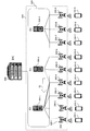
- FIG. 1 is a diagram illustrating a configuration example of a wireless communication system 10.
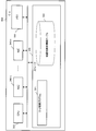
- FIG. 2 is a diagram illustrating an example of a configuration of the wireless communication system 10 when the CU 300 is virtualized.
- FIG. 3 is a diagram illustrating a configuration example of the CU 300.
- FIG. 4 is a diagram illustrating a configuration example of the DU 200.
- FIG. 5 is a diagram illustrating a configuration example of the CU construction device 600.
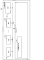
- FIG. 6 is a diagram illustrating an example of functional blocks of the base station device 500.
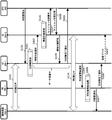
- FIG. 7 is a diagram illustrating an example of a sequence of control target DU change processing in the wireless communication system 10.
- FIG. 8 is a diagram illustrating an example of a process flowchart of the CU switching process.
- FIG. 8 is a diagram illustrating an example of a process flowchart of the CU switching process.
- FIG. 9 is a diagram illustrating an example of a process flowchart of the information transfer process S106.
- FIG. 10 is a diagram illustrating an example of a process flowchart of the CU switching start process S110.
- FIG. 11 is a diagram illustrating an example of a sequence of control target DU change processing in the wireless communication system 10.
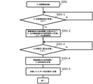
- FIG. 12 is a diagram illustrating an example of a process flowchart of the CU switching start process S201.
- FIG. 13 is a diagram illustrating an example of a sequence of control target DU change processing in the wireless communication system 10.
- FIG. 14 is a diagram illustrating an example of a process flowchart of the CU switching process S301.
- FIG. 15 is a diagram illustrating an example of a process flowchart of the CU switching start process S306.
- FIG. 16 is a diagram illustrating an example of layers managed by the base station apparatus.
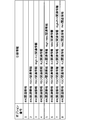
- FIG. 17 is a diagram illustrating an example of takeover information (control terminal information) for each option.
- the base station apparatus includes a plurality of radio units (DU) that are wirelessly connected to the terminal apparatus, and a plurality of control units (CU or virtualized CU) that control the radio unit to be controlled.
- the control unit stores terminal information (control terminal information) related to communication of the terminal device in communication with the radio unit to be controlled.
- a control part is the terminal information of the terminal device in communication with a 1st radio
- To the first control unit takeover).
- the control unit is a terminal of the terminal device that is communicating with the second radio unit. Information is acquired (taken over) from the second control unit.
- FIG. 1 is a diagram illustrating a configuration example of a wireless communication system 10.
- the wireless communication system 10 includes terminal apparatuses 100-1 to 100-9, DUs 200-1 to 9, CUs 300-1 to 3, and an EPC (Evolved Packet Core) 400.
- a configuration (or apparatus) including CUs 300-1 to 3 (hereinafter sometimes referred to as CU300) and DUs 200-1 to 9 (hereinafter also referred to as DU200) is referred to as a base station apparatus 500.
- Base station apparatus 500 includes at least one CU 300 and DU 200.
- the wireless communication system 10 is a communication system that provides wireless communication to the terminal devices 100-1 to 100-9 (hereinafter may be referred to as the terminal device 100), for example, in accordance with LTE (Long Term Evolution) or LTE Advanced. .
- LTE Long Term Evolution
- LTE Advanced Long Term Evolution Advanced
- the terminal device 100 is a mobile communication device such as a smartphone or a tablet terminal.
- the terminal device 100 wirelessly connects to the DU 200 when communicating with another device.
- the terminal device 100 communicates with other devices by transmitting and receiving packets including data via the CU 300 and the EPC 400 that are connected to the wirelessly connected DU 200.
- the DU 200 is a device that is wirelessly connected to the terminal device 100, for example, RRH (Remote Radio Radio Head).
- the DU 200 is connected to at least one CU 300 and is controlled by the connected CU 300.
- the CU 300 is a device that controls the DU 200, and is, for example, a BBU (Base Band Unit).
- the CU 300 manages communication of the terminal device 100 that is wirelessly connected to the DU 200 to be controlled.
- the EPC 400 is, for example, an MME (Mobility Management Entity) that controls C (Control) -Plane, an S-GW (Serving Gateway) that controls U (User) -plane, and a P-GW that relays connections to external networks. It is a core network having (Packet
- the CU 300 controls one or a plurality of DUs 200.
- the DU 200 controlled by the CU 300 may be referred to as a DU 200 to be controlled by the CU 300 or a DU 200 under the control of the CU 300.
- FIG. 2 is a diagram illustrating an example of the configuration of the wireless communication system 10 when the CU 300 is virtualized.
- the CU 300 may be virtualized in order to realize a high data rate, a large capacity, and a low delay.
- the CU 300 is a virtualized CU constructed by, for example, the CU construction device 600 executing a specific program.
- the CU construction device 600 is connected to the DU 200 by wire such as an optical cable, for example.
- the virtualized CU is connected to the DU 200 via the CU construction device 600. Therefore, the virtualized CU can change the DU 200 to be controlled (the control target) without changing the physical wired connection.
- the virtualized CU changes the DU 200 to be controlled in accordance with, for example, the processing load or the communication amount.
- whether or not to change the change of the control target DU may be determined by the EPC 400 based on the processing load or the memory usage rate of the CU 200, for example.
- the EPC 400 may be a virtualized device in the CU construction device 600. When the EPC 400 is a virtualized device, for example, the EPC 400 may be included in the base station device 500.
- the control target DU of the CU 300-1 is DU 200-1 to DU-3, and the control target DU of the CU 300-2 is DU 200-4 to 6.
- the EPC 400 detects that the processing load on the CU 300-2 is large. Then, the EPC 400 moves the DU 200-4 to be controlled by the CU 300-2 to the CU 300-1 having a relatively low processing load (S1).
- the DU 200 controlled by the CU 300 may be changed depending on the situation.
- FIG. 3 is a diagram illustrating a configuration example of the CU 300.
- the CU 300 includes a CPU (Central Processing Unit) 310, a storage 320, a memory 330, and NIC (Network Interface Card) 340-1 to 340-n.
- the CU 300 is a device that performs processing of the baseband unit of the base station device 500 and timing control in which the connected DU 200 transmits radio waves, and is a BBU, for example.
- the storage 320 is an auxiliary storage device that stores programs and data.
- the storage 320 stores a DU control program 321 and a control terminal information table 322.
- the control terminal information table 322 is a table that stores, for each terminal device 100, control terminal information of the terminal device 100 that is wirelessly connected to the control target DU of the CU 300.
- the control terminal information is information related to communication of the terminal device 100, and is connection information in a layer managed by the CU 300, for example.
- the control terminal information is a sequence number of the RRC layer or the like.
- the CU 300 can maintain the connection (connection) in the layer managed by the CU 300 with the terminal device 100 based on the stored control terminal information.
- the memory 330 is an area for loading a program stored in the storage 320.
- the memory 330 is also used as an area for storing data.
- NICs 340-1 to 340-n are devices that communicate with the DU 200 and the EPC 400.
- the NICs 340-1 to 340 -n may be connected to other devices via hubs or switches.
- the CPU 310 is a processor that loads a program stored in the storage 320 into the memory 330, executes the loaded program, and realizes each process.
- the CPU 310 executes the DU control program 321 to construct a control unit and perform DU control processing.
- the DU control process is a process in which the CU 300 controls the control target DU.
- the CU 300 relays communication of the terminal device 100 that is wirelessly connected to the control target DU.
- the CU 300 manages (terminates) processing in a specific layer in relaying communication of the terminal device 100.
- FIG. 4 is a diagram illustrating a configuration example of the DU 200.
- the DU 200 includes a CPU 210, a storage 220, a memory 230, a NIC 240, and an RF (Radio Frequency) circuit 250.
- the DU 200 is a device that performs processing related to radio of the base station device 500, and is, for example, RRH.
- the storage 220 is an auxiliary storage device that stores programs and data.
- the storage 220 stores a wireless control program 221 and a wireless terminal information table 222.
- the wireless terminal information table 222 is a table that stores, for each terminal device 100, wireless terminal information of the terminal device 100 that is wirelessly connected to the DU 200.
- the wireless terminal information is information related to communication of the terminal device 100, for example, connection information in a layer managed by the DU 200.
- the wireless terminal information is information such as frequency and retransmission control in the PHY layer.
- the DU 200 can maintain a wireless connection with the terminal device 100 based on the stored wireless terminal information.
- the memory 230 is an area for loading a program stored in the storage 220.
- the memory 230 is also used as an area for storing data.
- the NIC 240 is a device that communicates with the CU 300 and the CU construction device 600.
- the NIC 240 may be connected to another device via a hub or a switch.
- the RF circuit 250 is a device that is wirelessly connected to the terminal device 100 via an antenna.
- the RF circuit 250 communicates with the terminal device 100 located in the communication area via wireless communication.
- the CPU 210 is a processor that loads a program stored in the storage 220 into the memory 230, executes the loaded program, and realizes each process.
- the CPU 210 executes the wireless control program 221 to construct a wireless unit and perform wireless control processing.
- the wireless control process is a process for controlling the wireless communication with the terminal device 100 that is wirelessly connected to the DU 200.
- the DU 200 receives a data packet from the terminal device 100 and transmits the received packet to the CU 300 to be connected.
- FIG. 5 is a diagram illustrating a configuration example of the CU construction device 600.
- the CU construction apparatus 600 includes a CPU 610, a storage 620, a memory 630, and NICs 640-1 to 640-n.
- the CU construction device 600 is a device that activates a virtualized CU, and is, for example, a computer or a server machine.
- the storage 620 is an auxiliary storage device that stores programs and data.
- the storage 620 stores a CU activation program 621.
- the memory 630 is an area for loading a program stored in the storage 620.
- the memory 630 is also used as an area for storing data by the program.
- NICs 640-1 to n are devices that communicate with the DU 200 and the EPC 400.
- the NICs 640-1 to 640-n may be connected to other devices via hubs or switches.
- the CPU 610 is a processor that loads a program stored in the storage 620 into the memory 630, executes the loaded program, and realizes each process.
- the CPU 610 executes the CU activation program 621 to construct a virtualized CU (control unit) and performs the same processing as the CU 300.
- the CPU 610 executes the CU activation program 621 a plurality of times (for example, N times). Further, the CPU 610 can delete the constructed virtualized CU by deleting the process of the CU activation program 621.
- the virtualized CU has processes and tables similar to those of the CU300 described above.
- the CU construction device 600 may have a program for starting the virtualized EPC 400.
- the CU construction device 600 constructs the virtualized EPC 400 by executing a program for starting the virtualized EPC 400 with a processor.
- FIG. 6 is a diagram illustrating an example of functional blocks of the base station device 500.
- Base station apparatus 500 includes control unit 510 and radio unit 520.
- the control unit 510 is, for example, a CU 300 or a virtualized CU.
- the radio unit 520 is, for example, the DU 200.
- the control unit 510 includes a DU control process 511, a CU switching process 512, an information takeover process 513, and a control terminal information table 514.
- the DU control process 511 is the same as the DU control process performed by the CU 300.
- the control terminal information table 514 is a table similar to the control terminal information table 322.
- the CU switching process 512 is, for example, a subroutine of a DU control process, receives a CU switching instruction from the EPC 400, and designates a control target DU under its own CU 300 (hereinafter, referred to as a movement source CU) as another CU 300 ( Hereinafter, it is a process of changing to a subordinate of the destination CU).
- the target DU 200 to be changed under the destination CU may be referred to as a movement target DU.
- the CU 300 takes over control terminal information (also referred to as terminal information) of the movement target DU to the movement destination CU.
- the information takeover process 513 is, for example, a DU control process subroutine.
- the wireless unit 520 includes a wireless control process 521, a CU switching start process 522, and a wireless terminal information table 523.
- the radio control process 521 is the same as the radio control process performed by the DU 200.
- the wireless terminal information table 523 is the same table as the wireless terminal information table 222.
- the CU switching start processing 522 is, for example, a subroutine of wireless control processing, receives a CU switching start notification from the connected DU 200, and communicates with the terminal device 100 that is wirelessly connected until the CU switching is completed. This is a process for instructing to stop or limit the communication amount to a predetermined value or less (communication suppression).
- the base station apparatus 500 may have a management unit (not shown).
- the management unit has the same function as that of the EPC 400, monitors the processing load and the memory usage rate of the control unit 510, and changes (or determines the change) the wireless unit 520 that is the control target of the control unit 510.
- FIG. 7 is a diagram illustrating an example of a sequence of control target DU change processing in the wireless communication system 10.
- the sequence of FIG. 7 will be described by taking as an example the case where the layer controlled by the CU 300 is an RRC layer and the layer controlled by the DU 200 is a layer below the PDCP (Packet Data Convergence Protocol) layer.
- PDCP Packet Data Convergence Protocol
- the DU200-1 is a DU300-1 control target DU.
- the terminal device 100-1 is wirelessly connected to the DU 200-1, and has established a connection in the RRC layer with the CU 300-1 (S101).
- the CU 300-1 stores control terminal information (terminal information) of the terminal device 100-1 wirelessly connected to the DU 200-1 to be controlled in an internal table (for example, control terminal information table).
- the EPC 400 changes the control target DU of the CU 300 in order to monitor the processing load and processing data amount of the CU 300 and distribute the load of the CU 300, for example. For example, the EPC 400 detects that the processing load of the CU 300-1 has become larger than a predetermined value, and moves the DU 200-1 to be controlled by the CU 300-1 to the CU 300-2 having a relatively small processing load. In changing the control target DU, the EPC 400 transmits a CU switching instruction to the CU 300-1 that is the movement source CU (S102). The CU switching instruction is a message that causes the CU 300 to change the control target DU.
- the CU switching instruction includes, for example, the source CU, the movement target DU, and the identifier of the terminal device 100 that is wirelessly connected to the movement target DU.
- the CU 300-1 Upon receiving the CU switching instruction, the CU 300-1 performs a CU switching process (S103).
- FIG. 8 is a diagram illustrating an example of a process flowchart of the CU switching process.
- the CU 300 waits to receive a CU switching instruction (No in S103-1).
- the CU 300 transmits an information takeover notification to the destination CU (S103-2).
- the information takeover notification is a message for allowing the destination CU to take over control terminal information.
- the source CU generates an information takeover notification including the identifier of the terminal device that is wirelessly connected to the target DU and the control terminal information, and transmits the information to the destination CU.
- the control terminal information included in the information takeover notification is information necessary for maintaining a session in the RRC layer between the terminal device 100 and the CU 300, for example.
- the CU 300 transmits a CU switching start notification to the movement target DU (S103-3).
- the CU switching start notification is a message notifying the movement target DU that the process of switching the CU 300 to which the movement target DU is connected is started.
- the CU switching start notification includes, for example, the identifier and address of the destination CU.
- the CU 300 waits to receive an information takeover response (No in S103-4).
- the CU 300 transmits a CU switching completion notification to the movement target DU (S103-5).
- the CU switching completion notification is a message that notifies the movement target DU that the process of switching the CU 300 to which the movement target DU is connected has been completed.
- CU switching completion is a message that notifies the EPC 400 that handover of control terminal information has been completed between the source CU and destination CU.
- the CU 300-1 transmits an information takeover notification including the terminal information for control of the terminal device 100-1 to the CU 300-2 in the CU switching process S103 (S104, S103-2 of FIG. 8). . Then, in the CU switching process S103, the CU 300-1 transmits a CU switching start notification to the DU 200-1 (S105, S103-3 in FIG. 8).
- the CU 300-2 when receiving the information takeover notification, the CU 300-2 performs an information takeover process (S106).
- FIG. 9 is a diagram illustrating an example of a process flowchart of the information transfer process S106.
- the CU 300 waits to receive an information takeover notification (No in S106-1).
- the CU 300 stores the control terminal information included in the information takeover notification in the internal table (S106-2).
- the internal table is, for example, the control terminal information table 322.
- the CU 300 transmits a session switching request to the EPC 400 (S106-3).
- the session switching request is a message that requests the EPC 400 to switch the session between the CU 300 and the EPC 400 from the movement source CU to the movement destination CU.
- the CU 300 waits for reception of a session switching response (No in S106-4).
- the CU 300 transmits an information takeover response to the source CU (S106-5).
- the information takeover response is a message that notifies the source CU that the storage of the control terminal information and the switching of the session with the CU 300 in the EPC 400 have been completed.
- the CU 300-2 transmits a session switching request to the EPC 400 in the information takeover process S106 (S107, S106-3 in FIG. 9).
- the EPC 400 receives the session switching request and completes the session switching
- the EPC 400 transmits a session switching response to the CU 300-2 (S108).
- the CU 300-2 receives the session switching response in the information takeover process S106 (Yes in S106-4 in FIG. 9)
- the CU 300-2 transmits the information takeover response to the CU 300-1 (S109, S106-5 in FIG. 9).
- the DU 200-1 when receiving the CU switching start notification, the DU 200-1 performs a CU switching start process (S110).
- FIG. 10 is a diagram illustrating an example of a process flowchart of the CU switching start process S110.
- the DU 200 waits for reception of a CU switching start notification (No in S110-1).
- the CU 300 Upon receiving the CU switching start notification (Yes in S110-1), the CU 300 transmits a transmission stop request to the terminal device 100 that is wirelessly connected (S110-2).
- the transmission stop request is a message that requests (instructs) the terminal device 100 to temporarily stop wireless communication or to suppress communication that temporarily suppresses the transmission amount.
- the DU 200 waits to receive a CU switching completion notification (No in S110-3). Upon receiving the CU switching completion notification (Yes in S110-3), the DU 200 transmits a transmission stop cancellation request to the terminal device 100 that is wirelessly connected (S110-4).
- the transmission release stop request is a message requesting that the communication stopped by the transmission stop request or the transmission amount being suppressed be returned to the state before reception of the transmission stop request.
- the DU 200 transmits a CU change notification to the terminal device 100 that is wirelessly connected (S110-5).
- the CU change notification is a message that notifies the DU 200 that the CU 300 to which the DU 200 is connected (controls the DU 200) has been changed.
- the CU change notification includes, for example, the identifier and address of the destination CU.
- the DU 200-1 transmits a transmission stop request to the terminal device 100-1 in the CU switching start process S110 (S111).
- the terminal device 100 that has received the transmission stop request stops transmission to the DU 200-1 or suppresses the transmission amount.
- the CU 300-1 When the CU 300-1 receives the information takeover response in the CU switching process S103 (Yes in S103-4 in FIG. 8), the CU 300-1 transmits a CU switching completion notification to the DU 200-1 (S112, S103-5 in FIG. 8). Further, the CU 300-1 transmits CU switching completion to the EPC 400 (S113, S103-6 in FIG. 8).
- the DU 200-1 receives the CU switching completion notification (Yes in S110-3 in FIG. 10), and transmits a transmission stop cancellation request to the terminal device 100-1 (S114, S110 in FIG. 10). -4). Then, the DU 200-1 transmits a CU change notification to the terminal device 100-1 (S115, S110-5 in FIG. 10).
- the terminal device 100-1 and the CU 300-2 are in a state where a session in the RRC layer is established (S116).
- the control terminal information is taken over from the movement source CU to the movement destination CU.
- the terminal device 100 can take over the session established with the source CU to the destination CU, and can maintain communication without reconstructing the session.
- FIG. 11 is a diagram illustrating an example of a sequence of control target DU change processing in the wireless communication system 10.
- the terminal device 100 has established a connection in the RRC layer with the CU 300-1 (S101). Thereafter, the processing from S102 to S109 is the same as the processing from S102 to S109 shown in the sequence shown in FIG.
- the DU 200-1 When the DU 200-1 receives the CU switching start notification, the DU 200-1 performs a CU switching start process (S201).
- FIG. 12 is a diagram illustrating an example of a process flowchart of the CU switching start process S201.
- the DU 200 waits for reception of a CU switching start notification (No in S201-1).
- the CU 300 Upon receiving the CU switching start notification (Yes in S201-1), the CU 300 starts holding data transmitted to the wirelessly connected terminal device 100 and data received from the wirelessly connected terminal device 100 (S201). -2).
- the DU 200 stores data in time series in the internal memory, for example, when the data is suspended.
- the DU 200 waits to receive a CU switching completion notification (No in S201-3). Upon receiving the CU switching completion notification (Yes in S201-3), the DU 200 transmits a CU change notification to the terminal device 100 that is wirelessly connected (S201-4).
- the DU 200 transmits the held data to the transmission destination (S201-5). For example, the DU 200 transmits data addressed to the terminal device 100 to the terminal device 100. Further, the DU 200 transmits the data received from the terminal device 100 to the movement destination CU.
- the DU 200-1 suspends the data to be transmitted to the terminal device 100-1 and the data received from the terminal device 100-1 in the CU switching start processing S201.
- a transmission stop request is transmitted to the terminal device 100-1 (S111).
- the terminal device 100 that has received the transmission stop request stops transmission to the DU 200-1 or suppresses the transmission amount.
- the CU 300-1 Upon receiving the information takeover response in the CU switching process S103, the CU 300-1 transmits a CU switching completion notification to the DU 200-1 (S112). Further, the CU 300-1 transmits CU switching completion to the EPC 400 (S113).
- the DU 200-1 receives the CU switching completion notification (Yes in S201-3 in FIG. 12), and transmits a CU change notification to the terminal device 100-1 (S202, S201- in FIG. 12). 4).
- the DU 200-1 transmits the held data to the transmission destination in the CU switching start process S201 (S201-5 in FIG. 12).
- the DU 200-1 transmits data addressed to the terminal device 100-1 to the terminal device 100-1 (S204).
- the DU 200-1 transmits the data received from the terminal device 100-1 to the CU 300-2 that is the movement destination CU (S205).
- the data to be transmitted / received by the movement target DU to / from the terminal device 100 is suspended until the control target DU change process is completed.
- the data transmission / reception with the terminal device 100 in an unstable state until the update of the connection relationship with the CU 300, the EPC 400, and the DU 200 accompanying the change of the control target DU can be stopped.
- the terminal device 100 can transmit and receive the connection relationship update data (held data).
- the terminal device 100 can continue normal communication without being aware that the control target DU change process is being performed.
- the movement target DU suspended the data received from the terminal device 100 and the data to be transmitted to the terminal device 100.
- the source CU suspended the data. Do.
- FIG. 13 is a diagram illustrating an example of a sequence of control target DU change processing in the wireless communication system 10. Then, the terminal device 100-1 has established a connection in the RRC layer with the CU 300-1 (S101). Thereafter, the processing up to step S102 is the same as the processing up to step S102 shown in the sequence shown in FIG.
- the CU 300-1 When the CU 300-1 receives the CU switching instruction, the CU 300-1 performs a CU switching process (S301).
- FIG. 14 is a diagram illustrating an example of a process flowchart of the CU switching process S301.
- the CU 300 waits for reception of a CU switching instruction (No in S301-1).
- the CU 300 receives the CU switching instruction (Yes in S301-1)
- the CU 300 transmits an information takeover notification to the destination CU (S301-2).
- the CU 300 starts to hold the data transmitted to the movement target DU and the data received from the movement target DU (S301-3).
- the CU 300 waits to receive an information takeover response (No in S301-4). Upon receiving the information takeover response (Yes in S301-4), the CU 300 transmits a CU switching completion to the EPC 400 (S301-5). Then, the CU 300 transmits a CU switching start notification to the movement target DU (S301-6).
- the CU 300 waits to receive a CU switching completion notification (No in S301-7).
- the CU 300 receives the CU switching completion notification (Yes in S301-7)
- the CU 300 transmits the held data to the destination CU (S301-8).
- the CU 300-1 starts holding the data to be transmitted to the DU 200-1 and the data received from the DU 200-1 in the CU switching process S301.
- the CU 300-1 transmits an information takeover notification to the CU 300-2 (S302, S301-2 in FIG. 14).
- processing S106 to processing S109 are the same processing as processing S106 to processing S109 shown in the sequence of FIG.
- the CU 300-1 When the CU 300-1 receives the information takeover response in the CU switching process S301 (Yes in S301-4 in FIG. 14), the CU 300-1 transmits a CU switching completion to the EPC 400 (S303, S301-5 in FIG. 14). The CU 300-1 then transmits a CU switching start notification to the DU 200-1 in the CU switching process S301 (S304, S301-6 in FIG. 14).
- the DU 200-1 Upon receiving the CU switching start notification, the DU 200-1 performs a CU switching start process (S306).
- FIG. 15 is a diagram illustrating an example of a process flowchart of the CU switching start process S306.
- the DU 200 waits for reception of a CU switching start notification (No in S306-1).
- the DU 200 transmits a CU change notification to the terminal device 100 that is wirelessly connected (S306-2).
- the DU 200 transmits a CU switching completion notification to the source CU (S306-3).
- the DU 200-1 transmits a CU change notification in the CU switching start process (S307, S306-2 of FIG. 15). Then, the DU 200-1 transmits a CU switching completion notification to the CU 300-1 (S308, S306-3 in FIG. 15).
- the CU 300-1 receives the CU switching completion notification (Yes in S301-7 in FIG. 14) and transmits the held data to the CU 300-2 (S309, S301-8 in FIG. 14). ).
- the data transmitted / received by the movement source CU to / from the movement target DU 200 is suspended until the control target DU change process is completed. Thereby, data transmission / reception with the movement target DU in an unstable state until the update of the connection relationship with the CU 300, the EPC 400, and the DU 200 accompanying the change of the control target DU can be stopped.
- the movement target DU and the terminal device 100 continue normal communication without being aware that the control target DU change processing is being performed. can do.
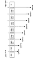
- FIG. 16 is a diagram illustrating an example of layers managed by the base station apparatus.
- the base station device 500 includes, for example, an RRC layer, a PDCP layer, a High-RLC (Radio Link Control) layer, a Low-RLC layer, a High-MAC (Medium Access Control) layer, and a Low-MAC layer. , High-PHY layer, and Low-PHY layer.
- RF is a function of transmitting / receiving radio waves to / from the terminal device 100, and is an RF circuit or an antenna included in the DU 200.
- the RRC layer is a layer that performs notification of system notification information, handover control of the terminal device 100, and the like. Further, the RRC layer may perform some NAS authentication.
- the PDCP layer is a layer that performs compression and decompression of duplicate IP (Internet Protocol) data and headers, and management of PDCP sequence numbers.
- the MAC layer is a layer that performs data mapping, error correction in HARQ (Hybrid Automatic repeat request), and allocation management of radio resources.
- the High-MAC layer is a layer having a part of functions of the MAC layer closer to the upper layer.
- the Low-MAC layer is a layer having functions other than the functions of the High-MAC layer among the functions of the MAC layer.
- the PHY layer is a layer that performs power control of transmitted / received radio waves (signals), measurement of error rates of transmitted / received radio waves, and the like.
- the High-PHY layer is a layer having a part of functions of the PHY layer closer to the higher layer.
- the Low-PHY layer is a layer having functions other than the functions of the High-PHY layer among the functions of the PHY layer.
- Option 1 is an option in which the CU 300 manages the RRC layer and the DU 200 manages from the PDCP layer to the Low-PHY layer.
- Option 2 is an option in which the CU 300 manages the RRC layer and the PDCP layer, and the DU 200 manages from the High-RLC layer to the Low-PHY layer.
- Option 3 is an option in which the CU 300 manages from the RRC layer to the High-RLC layer, and the DU 200 manages from the Low-RLC layer to the Low-PHY layer.
- Option 4 is an option for the CU 300 to manage from the RRC layer to the Low-RLC layer, and for the DU 200 to manage from the High-MAC layer to the Low-PHY layer.
- Option 5 is an option in which the CU 300 manages from the RRC layer to the High-MAC layer, and the DU 200 manages from the Low-MAC layer to the Low-PHY layer.
- Option 6 is an option in which the CU 300 manages the RRC layer to the Low-MAC layer, and the DU 200 manages the High-PHY layer and the Low-PHY layer.
- Option 7 is an option in which the CU 300 manages from the RRC layer to the High-PHY layer, and the DU 200 manages the Low-PHY layer.
- Option 8 is an option in which the CU 300 manages from the RRC layer to the Low-PHY layer, and the DU 200 has no layer to manage (only RF is managed).
- FIG. 17 is a diagram showing an example of takeover information (control terminal information) for each option. As shown in FIG. 17, the takeover information differs for each option. According to FIG. 17, the control terminal information for each option is information regarding a layer managed by the CU 300.
- the RRC related information is, for example, information related to the transmission timing of radio resources, a confidential parameter, and a security parameter.
- the PDCP related information is, for example, the IP header compression method, the received or transmitted PDCP sequence number.
- the MAC related information is, for example, a data mapping format and an ACK (acknowledgement) transmission mode.
- the High-MAC related information is information related to a part of functions of the MAC related information layer closer to the higher layer.
- the PHY related information is radio wave transmission power.
- the High-PHY related information is information related to a part of the functions of the PHY layer closer to the higher layer.
- the control target DU of the CU 300 can be changed.
- Wireless communication system 100 ... Terminal device 200 ... DU 210 ... CPU 220 ... Storage 221 ... Wireless control program 222 ... Wireless terminal information table 230 ... Memory 240 ... NIC 250 ... RF circuit 300 ... CU 310 ... CPU 320 ... Storage 321 ... DU control program 322 ... Control terminal information table 330 ... Memory 340 ... NIC 400 ... EPC 500 ... Base station device 510 ... Control unit 520 ... Radio unit 600 ... CU construction device 610 ... CPU 620 ... Storage 621 ... CU activation program 630 ... Memory 640 ... NIC
Landscapes
- Engineering & Computer Science (AREA)
- Computer Networks & Wireless Communication (AREA)
- Signal Processing (AREA)
- Mobile Radio Communication Systems (AREA)
Abstract
端末装置と無線接続する複数の無線部と、制御対象の無線部を制御する複数の制御部を有する基地局装置であって、前記制御部は、前記制御対象の無線部と通信中の端末装置の通信に関する端末情報を記憶し、前記制御対象の無線部である第1無線部が、自制御部以外の第1制御部の制御対象に変更されたとき、前記第1無線部と通信中の端末装置の端末情報を前記第1制御部に通知し、自制御部以外の第2制御部の制御対象である第2無線部が、自制御部の制御対象に変更されたとき、前記第2無線部と通信中の端末装置の端末情報を前記第2制御部から取得する。
Description
本発明は、基地局装置、無線通信システム、及び無線部切替方法に関する。
無線通信システムは、基地局装置が移動体通信端末と電波を送受信することで、無線通信を実現する。しかし、基地局装置がカバーしているエリア内でも、ビルなどの建造物で電波が遮蔽され電波が届きにくい場所や、多くの人が一斉に移動体通信端末を使用することで一時的に電波が不足する場所が存在する。そこで、基地局装置をCU(Central Unit)とDU(Distributed Unit)に分離し、電波を送受信するDUを増設することが可能な基地局装置(基地局システム)が増加している。
そして、次世代(例えば、5G(第5世代移動体通信))の通信規格では、4G(第4世代移動体通信)の標準技術に加えて、さらなる高データレート化、大容量化、低遅延化を実現する技術が求められている。そのため、5Gにおいては、例えば、CUを仮想化する通信システム(又は基地局装置)が検討されている。CUを仮想化することで、例えば、1台のコンピュータで複数のCUを構築し、CUの増減や、CUとDUの接続関係の変更など、通信システムの構成を状態に応じて変更することができる。
CUとDUが分離された基地局装置に関する技術については、以下の特許文献1~3に記載されている。
しかし、CUとDUの接続関係が変更されると、DUと無線接続している移動体通信端末とCUの関係も変更される。CUが、例えば、無線通信の機能を一連の層(レイヤ)に分割したプロトコルスタックにおけるRRC(Radio Resource Control)レイヤにおける制御を行っているとする。この場合、移動体通信端末は、無線通信中のDUが接続するCUが変更されるため、変更後のCUとRRCレイヤにおけるコネクションを再構築する。もしくは、この場合、移動体通信端末は、通信を切断し、再接続する必要がある。
そこで、開示の一つの目的は、DUとCUの接続関係が変更されても、端末装置の通信を継続する基地局装置、無線通信システム、及び無線部切替方法を提供することにある。
端末装置と無線接続する複数の無線部と、制御対象の無線部を制御する複数の制御部を有する基地局装置であって、前記制御部は、前記制御対象の無線部と通信中の端末装置の通信に関する端末情報を記憶し、前記制御対象の無線部である第1無線部が、自制御部以外の第1制御部の制御対象に変更されたとき、前記第1無線部と通信中の端末装置の端末情報を前記第1制御部に通知し、自制御部以外の第2制御部の制御対象である第2無線部が、自制御部の制御対象に変更されたとき、前記第2無線部と通信中の端末装置の端末情報を前記第2制御部から取得する。
一開示は、DUとCUの接続関係が変更されても、端末装置の通信を継続することができる。
[第1の実施の形態]
最初に第1の実施の形態について説明する。第1の実施の形態では、基地局装置は、端末装置と無線接続する複数の無線部(DU)と、制御対象の無線部を制御する複数の制御部(CU又は仮想化CU)を有する。制御部は、制御対象の無線部と通信中の端末装置の通信に関する端末情報(制御用端末情報)を記憶する。そして、制御部は、制御対象の無線部である第1無線部が、自制御部以外の第1制御部の制御対象に変更されたとき、第1無線部と通信中の端末装置の端末情報を第1制御部に通知する(引き継ぐ)。さらに、制御部は、自制御部以外の第2制御部の制御対象である第2無線部が、自制御部の制御対象に変更されたとき、第2無線部と通信中の端末装置の端末情報を第2制御部から取得する(引き継ぐ)。
最初に第1の実施の形態について説明する。第1の実施の形態では、基地局装置は、端末装置と無線接続する複数の無線部(DU)と、制御対象の無線部を制御する複数の制御部(CU又は仮想化CU)を有する。制御部は、制御対象の無線部と通信中の端末装置の通信に関する端末情報(制御用端末情報)を記憶する。そして、制御部は、制御対象の無線部である第1無線部が、自制御部以外の第1制御部の制御対象に変更されたとき、第1無線部と通信中の端末装置の端末情報を第1制御部に通知する(引き継ぐ)。さらに、制御部は、自制御部以外の第2制御部の制御対象である第2無線部が、自制御部の制御対象に変更されたとき、第2無線部と通信中の端末装置の端末情報を第2制御部から取得する(引き継ぐ)。
<無線通信システムの構成例>
図1は、無線通信システム10の構成例を示す図である。無線通信システム10は、端末装置100-1~9、DU200-1~9、CU300-1~3、及びEPC(Evolved Packet Core)400を有する。また、CU300-1~3(以下、CU300と呼ぶ場合がある)及びDU200-1~9(以下、DU200と呼ぶ場合がある)を含む構成(又は装置)を、基地局装置500と呼ぶ。基地局装置500は、少なくとも1つのCU300とDU200を有する。
図1は、無線通信システム10の構成例を示す図である。無線通信システム10は、端末装置100-1~9、DU200-1~9、CU300-1~3、及びEPC(Evolved Packet Core)400を有する。また、CU300-1~3(以下、CU300と呼ぶ場合がある)及びDU200-1~9(以下、DU200と呼ぶ場合がある)を含む構成(又は装置)を、基地局装置500と呼ぶ。基地局装置500は、少なくとも1つのCU300とDU200を有する。
無線通信システム10は、端末装置100-1~9(以下、端末装置100と呼ぶ場合がある)に無線通信を提供する、例えば、LTE(Long Term Evolution)やLTE Advanceに準拠した通信システムである。
端末装置100は、例えば、スマートフォンやタブレット端末などの移動体通信装置である。端末装置100は、例えば、他の装置と通信を行うとき、DU200と無線接続する。そして、端末装置100は、無線接続したDU200と接続するCU300、及びEPC400を介して、データを含むパケットを送受信することで、他の装置と通信を行う。
DU200は、端末装置100と無線接続する装置であり、例えば、RRH(Remote Radio Head)である。DU200は、少なくとも1つのCU300に接続し、接続したCU300に制御される。
CU300は、DU200を制御する装置であり、例えば、BBU(Base Band Unit)である。CU300は、制御対象のDU200に無線接続する端末装置100の通信を管理する。
EPC400は、例えば、C(Control)-Planeを制御するMME(Mobility Management Entity)や、U(User)-planeを制御するS-GW(Serving Gateway)及び外部ネットワークへの接続を中継するP-GW(Packet data network Gateway)を有するコアネットワークである。
CU300は、1又は複数のDU200を制御する。CU300が制御するDU200を、CU300の制御対象のDU200、又はCU300の配下のDU200と呼ぶ場合がある。
図2は、CU300を仮想化した場合の無線通信システム10の構成の例を示す図である。無線通信システム10においては、高データレート化、大容量化、低遅延化を実現するため、CU300を仮想化する場合がある。図2においては、CU300は、例えば、CU構築装置600が特定のプログラムを実行することで構築された、仮想化CUである。CU構築装置600は、例えば、光ケーブルなどの有線でDU200と接続する。一方、仮想化CUは、CU構築装置600を介してDU200と接続する。そのため、仮想化CUは、物理的な有線での接続を変更することなく、制御する(制御対象の)DU200を変更することが可能である。
仮想化CUは、例えば、処理負荷や通信量などに応じて、制御するDU200を変更する。なお、制御対象DUの変更を変更するか否かの判定は、例えば、EPC400がCU200の処理負荷やメモリ利用率に基づき、判定を行ってもよい。また、EPC400は、CU構築装置600において、仮想化された装置であってもよい。EPC400が仮想化された装置である場合、例えば、EPC400は基地局装置500に含まれてもよい。
図2において、初期状態では、CU300-1の制御対象DUはDU200-1~3であり、CU300-2の制御対象DUはDU200-4~6である。この状態において、例えば、EPC400は、CU300-2の処理負荷が大きくなっていることを検出する。そして、EPC400は、CU300-2の制御対象のDU200-4を、処理負荷が比較的低いCU300-1に移動させる(S1)。このように、無線通信システム10においては、CU300が制御するDU200は、状況に応じて変更される場合がある。
<CUの構成例>
図3は、CU300の構成例を示す図である。CU300は、CPU(Central Processing Unit)310、ストレージ320、メモリ330、及びNIC(Network Interface Card)340-1~nを有する。CU300は、基地局装置500のベースバンド部の処理や、接続するDU200が電波を送信するタイミング制御を実施する装置であり、例えば、BBUである。
図3は、CU300の構成例を示す図である。CU300は、CPU(Central Processing Unit)310、ストレージ320、メモリ330、及びNIC(Network Interface Card)340-1~nを有する。CU300は、基地局装置500のベースバンド部の処理や、接続するDU200が電波を送信するタイミング制御を実施する装置であり、例えば、BBUである。
ストレージ320は、プログラムやデータを記憶する補助記憶装置である。ストレージ320は、DU制御プログラム321及び制御用端末情報テーブル322を記憶する。
制御用端末情報テーブル322は、CU300の制御対象DUと無線接続中の端末装置100の制御用端末情報を、端末装置100ごとに記憶するテーブルである。制御用端末情報は、端末装置100の通信に関する情報であり、例えば、CU300が管理するレイヤにおける接続情報である。例えば、CU300が管理(終端)するレイヤがRRCレイヤである場合、制御用端末情報は、RRCレイヤのシーケンス番号などである。CU300は、記憶した制御用端末情報に基づき、端末装置100との、CU300の管理するレイヤにおける接続(コネクション)を維持することができる。
メモリ330は、ストレージ320に記憶されているプログラムをロードする領域である。また、メモリ330、プログラムがデータを記憶する領域としても使用される。
NIC340-1~nは、DU200やEPC400と接続し、通信を行う装置である。NIC340-1~nは、ハブやスイッチを介して他の装置と接続してもよい。
CPU310は、ストレージ320に記憶されているプログラムを、メモリ330にロードし、ロードしたプログラムを実行し、各処理を実現するプロセッサである。
CPU310は、DU制御プログラム321を実行することで、制御部を構築し、DU制御処理を行う。DU制御処理は、CU300が制御対象DUを制御する処理である。CU300は、DU制御処理において、制御対象DUに無線接続する端末装置100の通信を中継する。CU300は、端末装置100の通信の中継において、特定のレイヤにおける処理を管理(終端)する。
<DUの構成例>
図4は、DU200の構成例を示す図である。DU200は、CPU210、ストレージ220、メモリ230、NIC240、及びRF(Radio Frequency)回路250を有する。DU200は、基地局装置500の無線に関する処理を行う装置であり、例えば、RRHである。
図4は、DU200の構成例を示す図である。DU200は、CPU210、ストレージ220、メモリ230、NIC240、及びRF(Radio Frequency)回路250を有する。DU200は、基地局装置500の無線に関する処理を行う装置であり、例えば、RRHである。
ストレージ220は、プログラムやデータを記憶する補助記憶装置である。ストレージ220は、無線制御プログラム221及び無線用端末情報テーブル222を記憶する。
無線用端末情報テーブル222は、DU200と無線接続中の端末装置100の無線用端末情報を、端末装置100ごとに記憶するテーブルである。無線用端末情報は、端末装置100の通信に関する情報であり、例えば、DU200が管理するレイヤにおける接続情報である。例えば、DU200が管理(終端)するレイヤがPHY(Physical)レイヤである場合、無線用端末情報は、PHYレイヤにおける周波数や再送制御などの情報である。DU200は、記憶した無線用端末情報に基づき、端末装置100との無線接続を維持することができる。
メモリ230は、ストレージ220に記憶されているプログラムをロードする領域である。また、メモリ230、プログラムがデータを記憶する領域としても使用される。
NIC240は、CU300やCU構築装置600と接続し、通信を行う装置である。NIC240は、ハブやスイッチを介して他の装置と接続してもよい。
RF回路250は、アンテナを介して、端末装置100と無線接続する装置である。RF回路250は、例えば、通信エリア内に在圏する端末装置100と、無線を介して通信を行う。
CPU210は、ストレージ220に記憶されているプログラムを、メモリ230にロードし、ロードしたプログラムを実行し、各処理を実現するプロセッサである。
CPU210は、無線制御プログラム221を実行することで、無線部を構築し、無線制御処理を行う。無線制御処理は、DU200と無線接続する端末装置100との無線を制御する処理である。DU200は、無線制御処理において、端末装置100からデータパケットを受信し、接続するCU300に受信したパケットを送信する。
<CU構築装置の構成例>
図5は、CU構築装置600の構成例を示す図である。CU構築装置600は、CPU610、ストレージ620、メモリ630、及びNIC640-1~nを有する。CU構築装置600は、仮想化CUを起動する装置であり、例えば、コンピュータやサーバマシンである。
図5は、CU構築装置600の構成例を示す図である。CU構築装置600は、CPU610、ストレージ620、メモリ630、及びNIC640-1~nを有する。CU構築装置600は、仮想化CUを起動する装置であり、例えば、コンピュータやサーバマシンである。
ストレージ620は、プログラムやデータを記憶する補助記憶装置である。ストレージ620は、CU起動プログラム621を記憶する。
メモリ630は、ストレージ620に記憶されているプログラムをロードする領域である。また、メモリ630、プログラムがデータを記憶する領域としても使用される。
NIC640-1~nは、DU200やEPC400と接続し、通信を行う装置である。NIC640-1~nは、ハブやスイッチを介して他の装置と接続してもよい。
CPU610は、ストレージ620に記憶されているプログラムを、メモリ630にロードし、ロードしたプログラムを実行し、各処理を実現するプロセッサである。
CPU610は、CU起動プログラム621を実行することで、仮想化CU(制御部)を構築し、CU300と同様の処理を行う。CPU610は、複数(例えばN個)の仮想化CUを構築する場合、CU起動プログラム621を複数回(例えばN回)実行する。また、CPU610は、CU起動プログラム621のプロセスを消去することで、構築した仮想化CUを削除することができる。仮想化CUは、上述したCU300と同様の処理及びテーブルを有する。
なお、CU構築装置600は、仮想化したEPC400を起動するプログラムを有してもよい。CU構築装置600は、プロセッサで仮想化したEPC400を起動するプログラムを実行することで、仮想化したEPC400を構築する。
<基地局装置の機能構成>
図6は、基地局装置500の機能ブロックの例を示す図である。基地局装置500は、制御部510及び無線部520を有する。制御部510は、例えば、CU300又は仮想化CUである。また、無線部520は、例えば、DU200である。
図6は、基地局装置500の機能ブロックの例を示す図である。基地局装置500は、制御部510及び無線部520を有する。制御部510は、例えば、CU300又は仮想化CUである。また、無線部520は、例えば、DU200である。
制御部510は、DU制御処理511、CU切替処理512、情報引継処理513、及び制御用端末情報テーブル514を有する。
DU制御処理511は、CU300が行うDU制御処理と同様である。また、制御用端末情報テーブル514は、制御用端末情報テーブル322と同様のテーブルである。
CU切替処理512は、例えば、DU制御処理のサブルーチンであり、EPC400からCU切替指示を受信し、自CU300(以降、移動元CUと呼ぶ場合がる)の配下の制御対象DUを他のCU300(以降、移動先CUと呼ぶ場合がある)の配下に変更する処理である。以降、移動先CUの配下に変更する対象のDU200を、移動対象DUと呼ぶ場合がある。CU300は、CU切替処理において、移動先CUに移動対象DUの制御用端末情報(端末情報とも呼ぶ)を引き継ぐ。情報引継処理513は、例えば、DU制御処理のサブルーチンであり、自CU300が移動先CUであるとき、移動元CUから情報引継通知を受信し、自CU300内に移動対象DUの制御用端末情報を記憶する処理である。
無線部520は、無線制御処理521、CU切替開始処理522、及び無線用端末情報テーブル523を有する。
無線制御処理521は、DU200が行う無線制御処理と同様である。また、無線用端末情報テーブル523は、無線用端末情報テーブル222と同様のテーブルである。
CU切替開始処理522は、例えば、無線制御処理のサブルーチンであり、接続中のDU200からCU切替開始通知を受信し、CU切替が完了するまで、無線接続中の端末装置100に対して、通信を停止又は通信量を所定値以下に制限(通信抑制)するよう指示する処理である。
なお、基地局装置500は、図示しない管理部を有してもよい。管理部は、EPC400と同様の機能を有し、制御部510の処理負荷やメモリ利用率を監視し、制御部510の制御対象となる無線部520の変更(又は変更の決定)を行う。
<制御対象DU変更処理>
図7は、無線通信システム10における制御対象DU変更処理のシーケンスの例を示す図である。以下、CU300が制御するレイヤはRRCレイヤであり、DU200が制御するレイヤはPDCP(Packet Data Convergence Protocol)レイヤ以下のレイヤである場合を例として、図7のシーケンスを説明する。
図7は、無線通信システム10における制御対象DU変更処理のシーケンスの例を示す図である。以下、CU300が制御するレイヤはRRCレイヤであり、DU200が制御するレイヤはPDCP(Packet Data Convergence Protocol)レイヤ以下のレイヤである場合を例として、図7のシーケンスを説明する。
DU200-1は、CU300-1の制御対象DUである。そして、端末装置100-1は、DU200-1と無線接続中であり、CU300-1とRRCレイヤにおけるコネクションを確立している(S101)。CU300-1は、制御対象であるDU200-1と無線接続中の端末装置100-1の制御用端末情報(端末情報)を内部テーブル(例えば、制御用端末情報テーブル)に記憶する。
EPC400は、例えば、CU300の処理負荷や処理データ量を監視し、CU300の負荷を分散するため、CU300の制御対象DUを変更する。EPC400は、例えば、CU300-1の処理負荷が所定値より大きくなったことを検出し、CU300-1の制御対象のDU200-1を、処理負荷が比較的小さいCU300-2に移動させる。EPC400は、制御対象DUの変更において、移動元CUであるCU300-1に、CU切替指示を送信する(S102)。CU切替指示は、CU300に対して、制御対象DUを変更させるメッセージである。CU切替指示は、例えば、移動元CU、移動対象DU、及び移動対象DUと無線接続中の端末装置100の識別子が含まれる。CU300-1は、CU切替指示を受信すると、CU切替処理を行う(S103)。
図8は、CU切替処理の処理フローチャートの例を示す図である。CU300は、CU切替指示を受信するのを待ち受ける(S103-1のNo)。CU300は、CU切替指示を受信すると(S103-1のYes)、情報引継通知を移動先CUに送信する(S103-2)。情報引継通知は、移動先CUに制御用端末情報を引き継がせるためのメッセージである。移動元CUは、移動対象DUと無線接続中の端末装置の識別子及び制御用端末情報を含む情報引継通知を生成し、移動先CUに送信する。情報引継通知に含まれる制御用端末情報は、例えば、端末装置100とCU300間のRRCレイヤにおけるセッションを維持するのに必要な情報である。
そして、CU300は、CU切替開始通知を移動対象DUに送信する(S103-3)。CU切替開始通知は、移動対象DUの接続するCU300を切り替える処理を開始することを、移動対象DUに通知するメッセージである。CU切替開始通知は、例えば、移動先CUの識別子やアドレスが含まれる。
CU300は、情報引継応答を受信するのを待ち受ける(S103-4のNo)。CU300は、情報引継応答を受信すると(S103-4のYes)、CU切替完了通知を移動対象DUに送信する(S103-5)。CU切替完了通知は、移動対象DUの接続するCU300を切り替える処理が完了したことを、移動対象DUに通知するメッセージである。
そして、CU300は、CU切替完了をEPC400に送信する(S103-6)。CU切替完了は、移動元CUと移動先CU間で、制御用端末情報の引継ぎが完了したことを、EPC400に通知するメッセージである。
図7のシーケンスに戻り、CU300-1は、CU切替処理S103において、端末装置100-1の制御用端末情報を含む情報引継通知をCU300-2に送信する(S104、図8のS103-2)。そして、CU300-1は、CU切替処理S103において、DU200-1にCU切替開始通知を送信する(S105、図8のS103-3)。
一方、CU300-2は、情報引継通知を受信すると、情報引継処理を行う(S106)。
図9は、情報引継処理S106の処理フローチャートの例を示す図である。CU300は、情報引継通知を受信するのを待ち受ける(S106-1のNo)。CU300は、情報引継通知を受信すると(S106-1のYes)、情報引継通知に含まれる制御用端末情報を内部テーブルに記憶する(S106-2)。内部テーブルは、例えば、制御用端末情報テーブル322である。
そして、CU300は、制御用端末情報の内部テーブルへの記憶が完了すると、セッション切替要求をEPC400に送信する(S106-3)。セッション切替要求は、CU300とEPC400間のセッションを、移動元CUから移動先CUに切り替えるよう、EPC400に要求するメッセージである。
CU300は、セッション切替応答を受信するのを待ち受ける(S106-4のNo)。CU300は、セッション切替応答を受信すると(S106-4のYes)、情報引継応答を移動元CUに送信する(S106-5)。情報引継応答は、制御用端末情報の記憶、及びEPC400におけるCU300とのセッションの切替が完了したことを、移動元CUに通知するメッセージである。
図7のシーケンスに戻り、CU300-2は、情報引継処理S106において、セッション切替要求をEPC400に送信する(S107、図9のS106-3)。EPC400は、セッション切替要求を受信し、セッションの切替が完了すると、セッション切替応答をCU300-2に送信する(S108)。CU300-2は、情報引継処理S106において、セッション切替応答を受信すると(図9のS106-4のYes)、情報引継応答をCU300-1に送信する(S109、図9のS106-5)。
一方、DU200-1は、CU切替開始通知を受信すると、CU切替開始処理を行う(S110)。
図10は、CU切替開始処理S110の処理フローチャートの例を示す図である。DU200は、CU切替開始通知を受信するのを待ち受ける(S110-1のNo)。CU300は、CU切替開始通知を受信すると(S110-1のYes)、無線接続中の端末装置100に、送信停止要求を送信する(S110-2)。送信停止要求は、無線通信の一時的な停止、又は一時的に送信量を抑制する通信抑制を、端末装置100に要求(指示)するメッセージである。
DU200は、CU切替完了通知を受信するのを待ち受ける(S110-3のNo)。DU200は、CU切替完了通知を受信すると(S110-3のYes)、無線接続中の端末装置100に送信停止解除要求を送信する(S110-4)。送信解除停止要求は、送信停止要求により停止、又は送信量を抑制している通信を、送信停止要求受信前の状態に戻すよう要求するメッセージである。
そして、DU200は、無線接続中の端末装置100にCU変更通知を送信する(S110-5)。CU変更通知は、DU200が接続する(DU200を制御する)CU300が変更されたことを、DU200に通知するメッセージである。CU変更通知は、例えば、移動先CUの識別子やアドレスを含む。
図7のシーケンスに戻り、DU200-1は、CU切替開始処理S110において、送信停止要求を端末装置100-1に送信する(S111)。送信停止要求を受信した端末装置100は、DU200-1への送信を停止、又は送信量の抑制を行う。
CU300-1は、CU切替処理S103において、情報引継応答を受信すると(図8のS103-4のYes)、CU切替完了通知をDU200-1に送信する(S112、図8のS103-5)。さらに、CU300-1は、CU切替完了をEPC400に送信する(S113、図8のS103-6)。
DU200-1は、CU切替開始処理S110において、CU切替完了通知を受信し(図10のS110-3のYes)、端末装置100-1に送信停止解除要求を送信する(S114、図10のS110-4)。そして、DU200-1は、端末装置100-1にCU変更通知を送信する(S115、図10のS110-5)。
なお、CU300-2が端末装置100-1の制御用端末情報の記憶が完了したとき、端末装置100-1とCU300-2は、RRCレイヤにおけるセッションが確立された状態となる(S116)。
第1の実施の形態では、制御対象DU変更処理において、移動元CUから移動先CUに制御用端末情報を引き継ぐ。これにより、端末装置100は、移動元CUと確立中であったセッションを、移動先CUに引き継ぐことができ、セッションの再構築することなく通信を維持することができる。
[第2の実施の形態]
次に、第2の実施の形態について説明する。制御対象DU変更処理の実行中は、端末装置100、DU200、CU300、及びEPC400間それぞれのセッションを切り替え中であるため、データの送信経路が不安定である。そこで、第2の実施の形態では、移動対象DUが、端末装置100から受信したデータ、及び端末装置100に送信するデータを保留する。
次に、第2の実施の形態について説明する。制御対象DU変更処理の実行中は、端末装置100、DU200、CU300、及びEPC400間それぞれのセッションを切り替え中であるため、データの送信経路が不安定である。そこで、第2の実施の形態では、移動対象DUが、端末装置100から受信したデータ、及び端末装置100に送信するデータを保留する。
<制御対象DU変更処理>
図11は、無線通信システム10における制御対象DU変更処理のシーケンスの例を示す図である。そして、端末装置100は、CU300-1とRRCレイヤにおけるコネクションを確立している(S101)。以降、処理S102から処理S109までは、図7に示すシーケンスに示す処理S102から処理S109までと同様の処理である。
図11は、無線通信システム10における制御対象DU変更処理のシーケンスの例を示す図である。そして、端末装置100は、CU300-1とRRCレイヤにおけるコネクションを確立している(S101)。以降、処理S102から処理S109までは、図7に示すシーケンスに示す処理S102から処理S109までと同様の処理である。
DU200-1は、CU切替開始通知を受信すると、CU切替開始処理を行う(S201)。
図12は、CU切替開始処理S201の処理フローチャートの例を示す図である。DU200は、CU切替開始通知を受信するのを待ち受ける(S201-1のNo)。CU300は、CU切替開始通知を受信すると(S201-1のYes)、無線接続中の端末装置100に送信されるデータ、及び無線接続中の端末装置100から受信したデータの保留を開始する(S201-2)。DU200は、データの保留において、例えば、内部メモリに時系列でデータを記憶する。
DU200は、CU切替完了通知を受信するのを待ち受ける(S201-3のNo)。DU200は、CU切替完了通知を受信すると(S201-3のYes)、無線接続中の端末装置100にCU変更通知を送信する(S201-4)。
そして、DU200は、保留していたデータを送信先に送信する(S201-5)。DU200は、例えば、端末装置100宛てのデータを端末装置100に送信する。また、DU200は、端末装置100から受信したデータを、移動先CUに送信する。
図11のシーケンスに戻り、DU200-1は、CU切替開始処理S201において、端末装置100-1に送信するデータ、及び端末装置100-1から受信したデータを保留する。送信停止要求を端末装置100-1に送信する(S111)。送信停止要求を受信した端末装置100は、DU200-1への送信を停止、又は送信量の抑制を行う。
CU300-1は、CU切替処理S103において、情報引継応答を受信すると、CU切替完了通知をDU200-1に送信する(S112)。さらに、CU300-1は、CU切替完了をEPC400に送信する(S113)。
DU200-1は、CU切替開始処理S201において、CU切替完了通知を受信し(図12のS201-3のYes)、端末装置100-1にCU変更通知を送信する(S202、図12のS201-4)。
さらに、DU200-1は、CU切替開始処理S201において、保留していたデータを送信先に送信する(図12のS201-5)。DU200-1は、端末装置100-1宛てのデータを端末装置100-1に送信する(S204)。そして、DU200-1は、端末装置100-1から受信したデータを、移動先CUであるCU300-2に送信する(S205)。
第2の実施の形態では、制御対象DU変更処理が完了するまで、移動対象DUが端末装置100と送受信するデータを保留する。これにより、制御対象DUの変更にともなうCU300、EPC400、及びDU200との接続関係の更新が完了するまでの不安定な状態での端末装置100とのデータ送受信を停止することができる。また、端末装置100は、接続関係の更新が完了したとき、接続関係の更新中のデータ(保留したデータ)を送受信することができる。
また、第2の実施の形態では、制御対象DUがデータを保留するため、端末装置100は制御対象DU変更処理が行われていることを意識しないで、通常の通信を継続することができる。
[第3の実施の形態]
次に、第3の実施の形態について説明する。第2の実施の形態では、移動対象DUが、端末装置100から受信したデータ、及び端末装置100に送信するデータを保留したが、第3の実施の形態では、移動元CUがデータの保留を行う。
次に、第3の実施の形態について説明する。第2の実施の形態では、移動対象DUが、端末装置100から受信したデータ、及び端末装置100に送信するデータを保留したが、第3の実施の形態では、移動元CUがデータの保留を行う。
<制御対象DU変更処理>
図13は、無線通信システム10における制御対象DU変更処理のシーケンスの例を示す図である。そして、端末装置100-1は、CU300-1とRRCレイヤにおけるコネクションを確立している(S101)。以降、処理S102までの処理は、図7に示すシーケンスに示す処理S102までと同様の処理である。
図13は、無線通信システム10における制御対象DU変更処理のシーケンスの例を示す図である。そして、端末装置100-1は、CU300-1とRRCレイヤにおけるコネクションを確立している(S101)。以降、処理S102までの処理は、図7に示すシーケンスに示す処理S102までと同様の処理である。
CU300-1は、CU切替指示を受信すると、CU切替処理を行う(S301)。
図14は、CU切替処理S301の処理フローチャートの例を示す図である。CU300は、CU切替指示を受信するのを待ち受ける(S301-1のNo)。CU300は、CU切替指示を受信すると(S301-1のYes)、情報引継通知を移動先CUに送信する(S301-2)。
そして、CU300は、移動対象DUに送信されるデータ、及び移動対象DUから受信したデータの保留を開始する(S301-3)。
CU300は、情報引継応答を受信するのを待ち受ける(S301-4のNo)。CU300は、情報引継応答を受信すると(S301-4のYes)、CU切替完了をEPC400に送信する(S301-5)。そして、CU300は、CU切替開始通知を移動対象DUに送信する(S301-6)。
CU300は、CU切替完了通知を受信するのを待ち受ける(S301-7のNo)。CU300は、CU切替完了通知を受信すると(S301-7のYes)、保留していたデータを移動先CUに送信する(S301-8)。
図13のシーケンスに戻り、CU300-1は、CU切替処理S301において、DU200-1に送信するデータ、及びDU200-1から受信したデータの保留を開始する。CU300-1は、CU切替処理S301において、情報引継通知をCU300-2に送信する(S302、図14のS301-2)。以降、処理S106から処理S109までは、図7のシーケンスに示す処理S106から処理S109と同様の処理である。
CU300-1は、CU切替処理S301において、情報引継応答を受信すると(図14のS301-4のYes)、CU切替完了をEPC400に送信する(S303、図14のS301-5)。そして、CU300-1は、CU切替処理S301において、CU切替開始通知をDU200-1に送信する(S304、図14のS301-6)。
DU200-1は、CU切替開始通知を受信すると、CU切替開始処理を行う(S306)。
図15は、CU切替開始処理S306の処理フローチャートの例を示す図である。DU200は、CU切替開始通知を受信するのを待ち受ける(S306-1のNo)。DU200は、CU切替開始通知を受信すると、(S306-1のYes)、無線接続中の端末装置100にCU変更通知を送信する(S306-2)。そして、DU200は、移動元CUにCU切替完了通知を送信する(S306-3)。
図13のシーケンスに戻り、DU200-1は、CU切替開始処理において、CU変更通知を送信する(S307、図15のS306-2)。そして、DU200-1は、CU300-1に、CU切替完了通知を送信する(S308、図15のS306-3)。
CU300-1は、CU切替処理S301において、CU切替完了通知を受信し(図14のS301-7のYes),保留していたデータをCU300-2に送信する(S309、図14のS301-8)。
第3の実施の形態では、制御対象DU変更処理が完了するまで、移動元CUが移動対象DU200と送受信するデータを保留する。これにより、制御対象DUの変更にともなうCU300、EPC400、及びDU200との接続関係の更新が完了するまでの不安定な状態での移動対象DUとのデータ送受信を停止することができる。
また、第3の実施の形態では、移動元CUがデータを保留するため、移動対象DU及び端末装置100は、制御対象DU変更処理が行われていることを意識しないで、通常の通信を継続することができる。
[第4の実施の形態]
次に、第4の実施の形態について説明する。第1から第3の実施の形態において、CU300がRRCレイヤを管理し、DU200がPDCPレイヤ以下を管理する場合について説明した。しかし、CU300とDU200が管理するレイヤについては、複数のオプション(パターン)が考えられる。そこで、第4の実施の形態においては、CU300とDU200が管理するレイヤと、引継情報(制御用端末情報)について、オプションごとに説明する。
次に、第4の実施の形態について説明する。第1から第3の実施の形態において、CU300がRRCレイヤを管理し、DU200がPDCPレイヤ以下を管理する場合について説明した。しかし、CU300とDU200が管理するレイヤについては、複数のオプション(パターン)が考えられる。そこで、第4の実施の形態においては、CU300とDU200が管理するレイヤと、引継情報(制御用端末情報)について、オプションごとに説明する。
図16は、基地局装置が管理するレイヤの例を示す図である。無線通信システム10においては、基地局装置500は、例えば、RRCレイヤ、PDCPレイヤ、High-RLC(Radio Link Control)レイヤ、Low-RLCレイヤ、High-MAC(Medium Access Control)レイヤ、Low-MACレイヤ、High-PHYレイヤ、及びLow-PHYレイヤを管理する。RFは、端末装置100と電波の送受信を行う機能であり、DU200が有するRF回路やアンテナである。
RRCレイヤは、システム報知情報の報知、及び端末装置100のハンドオーバー制御などを行なうレイヤである。また、RRCレイヤは、一部のNAS認証を行ってもよい。
PDCPレイヤは、重複したIP(Internet Protocol)データ及びヘッダの圧縮と解凍、PDCPシーケンス番号の管理を行うレイヤである。
MACレイヤは、データのマッピング、HARQ(Hybrid Automatic repeat-request)におけるエラー訂正、無線リソースの割当管理などを行なうレイヤである。High-MACレイヤは、MACレイヤの機能のうち、より上位レイヤに近い一部の機能を有するレイヤである。Low-MACレイヤは、MACレイヤの機能のうち、High-MACレイヤが有する機能以外の機能を有するレイヤである。
PHYレイヤは、送受信する電波(信号)の電力制御、送受信する電波のエラーレートの測定などを行うレイヤである。High-PHYレイヤは、PHYレイヤの機能のうち、より上位レイヤに近い一部の機能を有するレイヤである。Low-PHYレイヤは、PHYレイヤの機能のうち、High-PHYレイヤが有する機能以外の機能を有するレイヤである。
オプション1(Option1)は、CU300がRRCレイヤを管理し、DU200がPDCPレイヤからLow-PHYレイヤまでを管理するオプションである。
オプション2(Option2)は、CU300がRRCレイヤ及びPDCPレイヤを管理し、DU200がHigh―RLCレイヤからLow-PHYレイヤまでを管理するオプションである。
オプション3(Option3)は、CU300がRRCレイヤからHigh-RLCレイヤまでを管理し、DU200がLow-RLCレイヤからLow-PHYレイヤまでを管理するオプションである。
オプション4(Option4)は、CU300がRRCレイヤからLow-RLCレイヤまでを管理し、DU200がHigh-MACレイヤからLow-PHYレイヤまでを管理するオプションである。
オプション5(Option5)は、CU300がRRCレイヤからHigh-MACレイヤまでを管理し、DU200がLow-MACレイヤからLow-PHYレイヤまでを管理するオプションである。
オプション6(Option6)は、CU300がRRCレイヤからLow-MACレイヤまでを管理し、DU200がHigh-PHYレイヤ及びLow-PHYレイヤを管理するオプションである。
オプション7(Option7)は、CU300がRRCレイヤからHigh-PHYレイヤまでを管理し、DU200がLow-PHYレイヤを管理するオプションである。
オプション8(Option8)は、CU300がRRCレイヤからLow-PHYレイヤまでを管理し、DU200は管理するレイヤがない(RFのみを管理する)オプションである。
図17は、オプションごとの引継情報(制御用端末情報)の例を示す図である。図17に示すように、オプションごとに引継情報が異なる。図17によると、オプションごとの制御用端末情報は、CU300が管理するレイヤに関する情報である。
RRC関連情報は、例えば、無線リソースの送信タイミングに関する情報、秘匿パラメータ、及びセキュリティパラメータである。
PDCP関連情報は、例えば、IPヘッダの圧縮方式、受信済み又は送信済みのPDCPシーケンス番号である。
MAC関連情報は、例えば、データのマッピングのフォーマット、ACK(acknowledgement)送信モードである。High-MAC関連情報は、MAC関連情報レイヤの機能のうち、より上位レイヤに近い一部の機能に関する情報である。
PHY関連情報は、電波の送信電力である。High-PHY関連情報は、PHYレイヤの機能のうち、より上位レイヤに近い一部の機能に関する情報である。
第4の実施の形態では、CU300が管理するレイヤに応じた制御用端末情報を移動元CUから移動先CUに引き継ぐことで、端末装置100との少なくともRRCレイヤレベルでのセッションを維持しつつ、CU300の制御対象DUを変更することができる。
10…無線通信システム
100…端末装置
200…DU
210…CPU
220…ストレージ
221…無線制御プログラム
222…無線用端末情報テーブル
230…メモリ
240…NIC
250…RF回路
300…CU
310…CPU
320…ストレージ
321…DU制御プログラム
322…制御用端末情報テーブル
330…メモリ
340…NIC
400…EPC
500…基地局装置
510…制御部
520…無線部
600…CU構築装置
610…CPU
620…ストレージ
621…CU起動プログラム
630…メモリ
640…NIC
100…端末装置
200…DU
210…CPU
220…ストレージ
221…無線制御プログラム
222…無線用端末情報テーブル
230…メモリ
240…NIC
250…RF回路
300…CU
310…CPU
320…ストレージ
321…DU制御プログラム
322…制御用端末情報テーブル
330…メモリ
340…NIC
400…EPC
500…基地局装置
510…制御部
520…無線部
600…CU構築装置
610…CPU
620…ストレージ
621…CU起動プログラム
630…メモリ
640…NIC
Claims (15)
- 端末装置と無線接続する複数の無線部と、
制御対象の無線部を制御する複数の制御部を有する基地局装置であって、
前記制御部は、
前記制御対象の無線部と通信中の端末装置の通信に関する端末情報を記憶し、
前記制御対象の無線部である第1無線部が、自制御部以外の第1制御部の制御対象に変更されたとき、前記第1無線部と通信中の端末装置の端末情報を前記第1制御部に通知し、
自制御部以外の第2制御部の制御対象である第2無線部が、自制御部の制御対象に変更されたとき、前記第2無線部と通信中の端末装置の端末情報を前記第2制御部から取得する
基地局装置。 - 前記端末情報は、前記端末装置と前記制御部との通信におけるセッションの維持に使用する情報を含む
請求項1記載の基地局装置。 - 前記端末情報は、前記制御部が管理するレイヤにおけるセッションである
請求項2記載の基地局装置。 - 前記制御部が管理するレイヤは、RRCレイヤを含む
請求項3記載の基地局装置。 - 前記無線部は、自無線部を制御対象とする制御部が変更されるとき、前記変更前の制御部が前記変更後の制御部へ端末情報を通知してから、前記変更後の制御部が前記通知された端末情報を取得するまで、前記無線部と通信中の第1端末装置に、通信量を抑制する通信抑制を行うよう指示する
請求項1記載の基地局装置。 - 前記無線部は、前記変更前の制御部が前記変更後の制御部へ端末情報を通知したとき、前記通信抑制を実行させるメッセージを前記第1端末装置に送信し、前記通知された端末情報を取得したとき、前記通信抑制を解除させるメッセージを前記第1端末装置に送信する
請求項5記載の基地局装置。 - 前記通信抑制は、前記第1端末装置と前記無線部との通信を停止することを含む
請求項5記載の基地局装置。 - 前記無線部は、自無線部を制御対象とする制御部が変更されるとき、前記変更前の制御部が前記変更後の制御部へ端末情報を通知してから、前記変更後の制御部が前記通知された端末情報を取得するまで、前記無線部と通信中の端末装置との間で送受信されるデータを保留する
請求項1記載の基地局装置。 - 前記無線部は、前記変更前の制御部が前記変更後の制御部へ端末情報を通知したとき、前記無線部と通信中の第1端末装置に送信するデータ及び前記第1端末装置から受信したデータを保留し、前記変更後の制御部が前記通知された端末情報を取得したとき、前記保留したデータを前記第1端末装置と前記変更後の制御部それぞれに送信する
請求項8記載の基地局装置。 - 前記制御部は、前記第1無線部が前記第1制御部の制御対象に変更されたとき、前記第1無線部と通信中の端末装置の端末情報を前記第1制御部に通知してから、前記第1制御部が前記通知れた端末情報を取得するまで、前記第1無線部との間で送受信されるデータを保留する
請求項1記載の基地局装置。 - 前記制御部は、前記端末情報を通知したとき、前記第1無線部に送信するデータ及び前記第1無線部から受信したデータを保留し、前記第1制御部が前記通知された端末情報を取得したとき、前記保留したデータを前記第1制御部に送信する
請求項10記載の基地局装置。 - 前記変更は、前記基地局装置を制御する制御装置からの指示に応答して行う
請求項1記載の基地局装置。 - さらに、前記複数の制御部を管理する管理部を有し、
前記管理は、前記複数の制御部それぞれの処理負荷に応じて、前記変更を行う
請求項1記載の基地局装置。 - 端末装置と無線接続する複数の無線部と、制御対象の無線部を制御する複数の制御部を有する基地局装置における無線部切替方法であって、
前記制御部において、
前記制御対象の無線部と通信中の端末装置の通信に関する端末情報を記憶し、
前記制御対象の無線部である第1無線部が、自制御部以外の第1制御部の制御対象に変更されたとき、前記第1無線部と通信中の端末装置の端末情報を前記第1制御部に通知し、
自制御部以外の第2制御部の制御対象である第2無線部が、自制御部の制御対象に変更されたとき、前記第2無線部と通信中の端末装置の端末情報を前記第2制御部から取得する
無線部切替方法。 - 端末装置と、
前記端末装置と無線接続する複数の無線部と、制御対象の無線部を制御する複数の制御部を有する基地局装置と、
前記基地局装置を管理する管理装置を有する無線通信システムであって、
前記基地局装置の制御部は、前記制御対象の無線部と通信中の端末装置の通信に関する端末情報を記憶し、
前記管理装置は、前記基地局装置の第1無線部を、第2制御部から第1制御部に変更し、
前記基地局装置の前記第2制御部は、前記第1無線部と通信中の端末装置の端末情報を前記第1制御部に通知し、
前記基地局装置の前記第1制御部は、前記通知された端末情報を前記第2制御部から取得する
無線通信システム。
Priority Applications (1)
| Application Number | Priority Date | Filing Date | Title |
|---|---|---|---|
| PCT/JP2017/016310 WO2018198178A1 (ja) | 2017-04-25 | 2017-04-25 | 基地局装置、無線通信システム、及び無線部切替方法 |
Applications Claiming Priority (1)
| Application Number | Priority Date | Filing Date | Title |
|---|---|---|---|
| PCT/JP2017/016310 WO2018198178A1 (ja) | 2017-04-25 | 2017-04-25 | 基地局装置、無線通信システム、及び無線部切替方法 |
Publications (1)
| Publication Number | Publication Date |
|---|---|
| WO2018198178A1 true WO2018198178A1 (ja) | 2018-11-01 |
Family
ID=63918132
Family Applications (1)
| Application Number | Title | Priority Date | Filing Date |
|---|---|---|---|
| PCT/JP2017/016310 Ceased WO2018198178A1 (ja) | 2017-04-25 | 2017-04-25 | 基地局装置、無線通信システム、及び無線部切替方法 |
Country Status (1)
| Country | Link |
|---|---|
| WO (1) | WO2018198178A1 (ja) |
Cited By (2)
| Publication number | Priority date | Publication date | Assignee | Title |
|---|---|---|---|---|
| JP2021158602A (ja) * | 2020-03-27 | 2021-10-07 | 株式会社Nttドコモ | 無線通信システム、制御装置及び制御方法 |
| US11991578B2 (en) | 2019-04-01 | 2024-05-21 | Fujitsu Limited | Base station device, terminal device, wireless communication system, and connection change method |
Citations (5)
| Publication number | Priority date | Publication date | Assignee | Title |
|---|---|---|---|---|
| WO2011111111A1 (ja) * | 2010-03-12 | 2011-09-15 | 富士通株式会社 | 通信区間設定方法、中継局、移動通信システム |
| JP2012134708A (ja) * | 2010-12-21 | 2012-07-12 | Fujitsu Ltd | 無線通信システム |
| JP2013121066A (ja) * | 2011-12-07 | 2013-06-17 | Kddi Corp | 無線制御装置、移動通信システムおよびコンピュータプログラム |
| JP2014514848A (ja) * | 2011-04-12 | 2014-06-19 | アルカテル−ルーセント | 無線アクセス・ネットワークにおける負荷平衡化の概念 |
| WO2016054183A1 (en) * | 2014-09-30 | 2016-04-07 | Viavi Solutions, Inc. | Methods and apparatus for self optimization and/or improvement of a cloud-based wireless network |
-
2017
- 2017-04-25 WO PCT/JP2017/016310 patent/WO2018198178A1/ja not_active Ceased
Patent Citations (5)
| Publication number | Priority date | Publication date | Assignee | Title |
|---|---|---|---|---|
| WO2011111111A1 (ja) * | 2010-03-12 | 2011-09-15 | 富士通株式会社 | 通信区間設定方法、中継局、移動通信システム |
| JP2012134708A (ja) * | 2010-12-21 | 2012-07-12 | Fujitsu Ltd | 無線通信システム |
| JP2014514848A (ja) * | 2011-04-12 | 2014-06-19 | アルカテル−ルーセント | 無線アクセス・ネットワークにおける負荷平衡化の概念 |
| JP2013121066A (ja) * | 2011-12-07 | 2013-06-17 | Kddi Corp | 無線制御装置、移動通信システムおよびコンピュータプログラム |
| WO2016054183A1 (en) * | 2014-09-30 | 2016-04-07 | Viavi Solutions, Inc. | Methods and apparatus for self optimization and/or improvement of a cloud-based wireless network |
Cited By (4)
| Publication number | Priority date | Publication date | Assignee | Title |
|---|---|---|---|---|
| US11991578B2 (en) | 2019-04-01 | 2024-05-21 | Fujitsu Limited | Base station device, terminal device, wireless communication system, and connection change method |
| JP2021158602A (ja) * | 2020-03-27 | 2021-10-07 | 株式会社Nttドコモ | 無線通信システム、制御装置及び制御方法 |
| WO2021200567A1 (ja) * | 2020-03-27 | 2021-10-07 | 株式会社Nttドコモ | 無線通信システム、制御装置及び制御方法 |
| JP7576401B2 (ja) | 2020-03-27 | 2024-10-31 | 株式会社Nttドコモ | 無線通信システム |
Similar Documents
| Publication | Publication Date | Title |
|---|---|---|
| JP6995995B2 (ja) | 多重接続のための方法およびその装置 | |
| EP3634034B1 (en) | Communication method and apparatus | |
| US12089102B2 (en) | Data transmission method and related device | |
| CA3062360C (en) | Handover method, apparatus, system, computer program storage medium and chip system | |
| EP3823411A1 (en) | Control method for user equipment, and user equipment | |
| US11711711B2 (en) | Method for configuring measurement gap, access network device and terminal | |
| CN111602462A (zh) | 用户设备、节点以及在其中执行的方法 | |
| US20230117489A1 (en) | Relay determining method and apparatus, relay configuration method and apparatus, terminal, and network side device | |
| JP2021515465A (ja) | SpCell選択の支援情報 | |
| EP3142442B1 (en) | Method, device and system for controlling air interface resources | |
| US9357580B2 (en) | Method for switching communication connection mode, communication system, base station, transmitter and receiver | |
| KR20200117005A (ko) | Pdcp 중복 메커니즘의 활성화 방법 및 노드 기기 | |
| CN119054316A (zh) | 支持体验质量(QoE)测量收集的方法及设备 | |
| CN109076405A (zh) | 异制式小区间切换的方法及装置 | |
| TWI775811B (zh) | 通信方法、輔網絡節點和終端 | |
| WO2021026706A1 (zh) | 一种f1接口管理方法及装置 | |
| KR20210078482A (ko) | 리소스 제어 상태 변경 및 다중 노드 연결의 효율적인 처리 | |
| KR102246493B1 (ko) | 이동통신 시스템에서 멀티 셀 네트워크 구축 방법 및 장치 | |
| US8305976B1 (en) | Efficient wireless communication network entry for wireless communication devices | |
| WO2018198178A1 (ja) | 基地局装置、無線通信システム、及び無線部切替方法 | |
| KR101460330B1 (ko) | 이동 통신 시스템 및 그 시스템에서의 무선 연결 재설정 방법 | |
| JP2025536989A (ja) | シングル接続を用いたフォールバック条件付きハンドオーバー構成 | |
| CN105264942B (zh) | 一种数据传输发射端设备、接收端设备和方法 | |
| CN118524457A (zh) | 一种小区配置方法和设备 | |
| WO2026031977A1 (zh) | 信息传输方法及通信装置 |
Legal Events
| Date | Code | Title | Description |
|---|---|---|---|
| 121 | Ep: the epo has been informed by wipo that ep was designated in this application |
Ref document number: 17907736 Country of ref document: EP Kind code of ref document: A1 |
|
| NENP | Non-entry into the national phase |
Ref country code: DE |
|
| 122 | Ep: pct application non-entry in european phase |
Ref document number: 17907736 Country of ref document: EP Kind code of ref document: A1 |
|
| NENP | Non-entry into the national phase |
Ref country code: JP |