WO2018197887A1 - Système de gestion d'énergie - Google Patents
Système de gestion d'énergie Download PDFInfo
- Publication number
- WO2018197887A1 WO2018197887A1 PCT/GB2018/051108 GB2018051108W WO2018197887A1 WO 2018197887 A1 WO2018197887 A1 WO 2018197887A1 GB 2018051108 W GB2018051108 W GB 2018051108W WO 2018197887 A1 WO2018197887 A1 WO 2018197887A1
- Authority
- WO
- WIPO (PCT)
- Prior art keywords
- energy
- supply
- asset
- parameter
- building
- Prior art date
Links
Images


Classifications
-
- H—ELECTRICITY
- H02—GENERATION; CONVERSION OR DISTRIBUTION OF ELECTRIC POWER
- H02J—CIRCUIT ARRANGEMENTS OR SYSTEMS FOR SUPPLYING OR DISTRIBUTING ELECTRIC POWER; SYSTEMS FOR STORING ELECTRIC ENERGY
- H02J3/00—Circuit arrangements for ac mains or ac distribution networks
- H02J3/28—Arrangements for balancing of the load in a network by storage of energy
- H02J3/32—Arrangements for balancing of the load in a network by storage of energy using batteries with converting means
-
- G—PHYSICS
- G05—CONTROLLING; REGULATING
- G05B—CONTROL OR REGULATING SYSTEMS IN GENERAL; FUNCTIONAL ELEMENTS OF SUCH SYSTEMS; MONITORING OR TESTING ARRANGEMENTS FOR SUCH SYSTEMS OR ELEMENTS
- G05B15/00—Systems controlled by a computer
- G05B15/02—Systems controlled by a computer electric
-
- G—PHYSICS
- G06—COMPUTING; CALCULATING OR COUNTING
- G06F—ELECTRIC DIGITAL DATA PROCESSING
- G06F1/00—Details not covered by groups G06F3/00 - G06F13/00 and G06F21/00
- G06F1/26—Power supply means, e.g. regulation thereof
- G06F1/28—Supervision thereof, e.g. detecting power-supply failure by out of limits supervision
-
- H—ELECTRICITY
- H02—GENERATION; CONVERSION OR DISTRIBUTION OF ELECTRIC POWER
- H02J—CIRCUIT ARRANGEMENTS OR SYSTEMS FOR SUPPLYING OR DISTRIBUTING ELECTRIC POWER; SYSTEMS FOR STORING ELECTRIC ENERGY
- H02J3/00—Circuit arrangements for ac mains or ac distribution networks
- H02J3/003—Load forecast, e.g. methods or systems for forecasting future load demand
-
- Y—GENERAL TAGGING OF NEW TECHNOLOGICAL DEVELOPMENTS; GENERAL TAGGING OF CROSS-SECTIONAL TECHNOLOGIES SPANNING OVER SEVERAL SECTIONS OF THE IPC; TECHNICAL SUBJECTS COVERED BY FORMER USPC CROSS-REFERENCE ART COLLECTIONS [XRACs] AND DIGESTS
- Y04—INFORMATION OR COMMUNICATION TECHNOLOGIES HAVING AN IMPACT ON OTHER TECHNOLOGY AREAS
- Y04S—SYSTEMS INTEGRATING TECHNOLOGIES RELATED TO POWER NETWORK OPERATION, COMMUNICATION OR INFORMATION TECHNOLOGIES FOR IMPROVING THE ELECTRICAL POWER GENERATION, TRANSMISSION, DISTRIBUTION, MANAGEMENT OR USAGE, i.e. SMART GRIDS
- Y04S10/00—Systems supporting electrical power generation, transmission or distribution
- Y04S10/50—Systems or methods supporting the power network operation or management, involving a certain degree of interaction with the load-side end user applications
Definitions
- This invention relates to a building energy management system to optimise costs for a user of energy and to assist suppliers of electric power better to regulate demand for electricity.
- HVAC building technical services
- lighting etc. the energy consumption of devices used by the building. They provide the information and the tools that building system managers need both to understand the energy usage of their buildings and to control and improve their buildings’ energy performance.
- legacy systems do not use artificial intelligence automatically to control a system rather they provide a human manager with tools and information better to control the consumption of energy.
- More recently limited artificial intelligence systems such as that of BuildingIQ®, continuously obtains data on the local weather forecast, the occupancy for the building, energy prices, tariffs and demand response signals. Based on those inputs, such systems run thousands of simulations to arrive at the most efficient operating strategy for the following 24 hours. They then communicate to the building management system to make changes to the building heating, cooling and ventilation to optimise their settings.
- a method of managing energy in an energy consuming and storage system used for ventilating, heating and/or cooling a space, said system being connected to an electric supply comprises:
- the parameter is normally frequency but voltage may also be used.
- all energy cost means the total cost incurred by a system in a site over a predetermined period.
- the predetermined period may be a relative short time of hours or a longer period of days depending on the nature of the storage systems used on the site concerned.
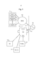
- Figure 1 is a schematic illustration of an example control system for a building using the method of the present invention
- Figure 2 is a schematic diagram of an air cooling asset
- Figures 3A to 3E illustrate the use of various energy management methods, including that of the invention in figure 3D, on the cooling system of figure 2.
- a building or group of buildings 101 contains a number of ventilation, heating and/or cooling devices Asset 1, Asset 2, Asset 3...Asset N. deployed in individual rooms or areas of the building or group of buildings 101.
- the Assets 1, 2, 3 ...N have the capability of storing energy either alone or collectively.
- the energy storage may, for example, be in in form of a heat sink, battery, fly-wheel, up-hill pumping device or other.
- the ventilation, heating and/or cooling of the building or group of buildings 101 is controlled by a building energy management system 103 which switches on and off the Assets 1, 2, 3...N and causes them to store energy.
- the Assets 1, 2, 3...N draw power 141 from the grid 105; the power draw-down for each is controlled by the building energy management system 103 using Ethernet or Wi-Fi connections (the individual power connections to each asset are omitted for clarity).
- a broadband connection 131 links the building energy management system 103 to a server or servers 107 which may be remote from or collocated with the building or group of buildings 101.
- the server provides an artificial neural network to generate predictive information over time 115 concerning energy requirements based on known consumption patterns of the Assets 1, 2, 3...N obtained from those assets through the building energy management system 103. This information is stored as a profile 113 in respect of each Asset 1,2,3...N for individual days of the week to reflect usage patterns, which may vary from one day to another.
- Predicted and spot energy cost information 109 is obtained from the electricity supplier and fed to the cost model for the assets.
- Meteorological information 111 particularly temperature and humidity predictions for the immediate future in the locality of the building or group of buildings 101, is downloaded to the server(s) 107.
- the neural network on the server 107 is a regression-based predictive learning programme which continually updates the profiles 113 based on experience, in this way the profiles become ”smarter” or more reflective of reality as time passes.
- the meteorological information 111 By combining the meteorological information 111 with the asset profiles 113, it is possible to gain a prediction on an hour by hour / minute by minute basis of the forthcoming energy needs of the assets. By combining this with the cost information 109, it is possible to predict costs and programme to Building Energy Management system to prepare an energy draw-down profile to draw power from the grid 105 when the energy costs are at their lowest and cause the Assets 1, 2, 3...N to store enough excess energy for use when energy cost are high so that the Assets 1, 2, 3...N do not have to draw energy from the grid 105 at times of predicted higher costs.
- the embodiment shown in figure 1 goes further than this.
- the neural network on the server 107 identifies when there is excess power in the grid 105 because the frequency of the grid increases, say, by 1% above the nominal frequency (50Hz in the UK).
- the server 107 switches the building energy management system to cause the Assets 1, 2, 3...N to take and store energy up to a pre-set maximum. If that draw down, plus what would be drawn down following the energy profile at a particular time would take takes the asset concerned above its available capacity, preference is given to drawing down excess energy off the grid (rather than following the pre-set profile) so that the management system always guarantees to the electricity supplier the availability of capacity to absorb excess energy up to an agreed maximum.
- the ability to absorb excess energy up to a maximum can be agreed with the energy supplier on a time basis, so that the capacity described is only available to the grid at certain times of day or week. .
- Figure 2 show a schematic diagram of a cooling unit, which may be one of the assets to which the system of figure 1 was applied.
- the unit comprises a duct 201 in which fans 202 are mounted driving air from a closed space, such as a room, through a heat exchanger 203 to a chiller.
- Warm air from the chiller passes through the heat exchanger 203 giving up heat to a fluid passing through the heat exchanger from a cold duct 212 from the bases of fluid storage tanks 211 to a duct 213 which takes the warmed fluid to the top of the fluid storage tanks.
- Warmed fluid is taken from the tops of the tanks 211 through warm fluid ducts 224 to an electric chiller 221 or an absorption chiller 222. In the chillers the fluid is cooled and passed back to the bottom of the tanks 211 through cool fluid ducts 223.
- the use of the tanks 211 gives the unit considerable storage capacity for cooled fluid.
- a store of cooled fluid is built up for later use.
- the tanks 211 act as energy batteries in the system.
- the heat exchanger 203 would be connected directly to the chillers 221 or 222, without the tanks 211. In this case the maximum demand on the chillers would occur at times of the day when external temperatures were at their highest and, probably, when similar equipment elsewhere is demanding energy resources leading to a shortage of supply in the electricity grid.
- energy can be taken from the grid at times of low cost and/or excess supply, and not taken when there is a supply shortfall and/or when cost is high.
- Figures 3A to 3E illustrate the beneficial impact of the energy management system of the invention applied to an asset illustrated in figure 2.
- FIG 3A a typical pricing structure for the supply of electricity to commercial premises is shown.
- a standard tariff applies 301.
- the price 302 is low, about half the standard tariff, reflecting low demand at this time.
- the price is high 303, reflecting high demand for electric energy at this time.
- Figure 3B shows the energy demands of the asset of figure 2 bars 310 and the energy losses from the asset bars 311, primarily as a result of fluid storage in the tanks.
- the asset of figure 2 in this mode is operating with a conventional building energy management system which controls energy provision to the assets based on previous patterns of requirements, meteorological information, i.e. predictions of the outside temperature. Thus the system tends to draw energy from the grid to meet short term predictions and needs.
- the electrical energy taken from the grid at any time is shown by bars 322, with line 321 showing the stored energy (in the case of the asset in figure 2); this is in the form of chilled fluid in tanks 211.
- the stored energy is represent by line 324. It can be seen that the system has about 50% redundancy in its energy storage capacity, but the system is also taking considerable amounts of energy from the grid at the peak period between 17 30 and 20 30.
- Figure 3C shows the same system, but now using energy price information.
- the system draws energy up to its total capacity, when the price is lowest but taking account of predicted future demands.
- the pattern of energy consumption 310 in this model is the same as that of the model control by an existing standard building energy management system,
- the asset prioritises taking energy from the grid between 03 30 and 06 30 when the tariff is lowest, storing that energy in the tanks 211 as cooled fluid and not taking further energy from the system until the sored energy has reduced to about 10% of stored energy capacity about 11 30; as the tariff at that time is the standard tariff it draws sufficient energy to maintain the store at 10% of capacity, but does not draw any excess for the time being.
- a time of high demand is between 17 30 and 20 30 exactly when the electricity supply tariff is at its highest.
- the system anticipates the high demand and stores sufficient energy to meet that demand between 16 30 and 17 30 when the standard tariff applies (the standard tariff being approximately half the peak tariff).
- the energy stored in the system is shown by line 331, which can be seen to be rising to a peak after energy is drawn from the grid for storage purposes when power is relatively cheaper and dropping as energy is taken from the tanks 211 and used during periods when energy is relatively more expensive.
- line 331 drops to 10% of capacity when storage is simply matching demand.
- the energy storage pattern has changed from that in figure 3B, the pattern of energy losses from the asset represented by line 311 changes. The losses are higher than those in figure 3B immediately after energy recharging but lower when energy storage is reduced to 10% of capacity. Overall the total losses are reduced by 44% from the previous value and running costs reduced by 17.6% compared with the conventional building energy management system of figure 3B.
- the system is organised not to demand more than 50% of the input capacity at any one time, with the remaining 50% of capacity made available to the energy in the grid. This is controlled by monitoring the frequency of the grid as described with reference to figure 1 and allowing power to flow to the until and to be stored in the tanks 211 up to the available capacity for a short time. The monitoring system also identifies a shortfall of generation capacity on the grid, by a drop in frequency on the grid. The system stops the asset taking power. This latter capability will become even more important as electricity supply companies increasingly move to the spot pricing of major commercial consumers, where the price relates the actual demand at any time.
- Figure 3D illustrates the effect of use of an energy management system as described in figure 1 in connection with an energy consuming asset shown in figure 2.
- the energy management system limits the power take of the asset represented by bars 342 to 50% of capacity, the other 50% shown by bars 343 being available to the grid for off-load of excess power.
- the output of the asset at any time represented by bars 310 is unchanged, but the rate of replenishment of energy stored in tanks 211 (figure 2) is spread over longer periods. But as these periods are at time when energy costs are below the peak costs there is no difference from the model of figure 3C for the costs for total energy supplied.
- the asset has resilience to withstand withdrawal of supplies for short periods when demands on the grid are high, and this can be done when the frequency in the grid is detected to have dropped below a present level, say 1% below the nominal frequency (50Hz in the UK).
- Table 1 below illustrated the impact of the models of figures 3B, 3C and 3D.
- Table 1 Input/output capacity 100 Kwh Conventional prior art building energy management – Figure 3B Price sensitive building energy management – Figure 3C Building energy management according to the invention – Figure 3D Power usage Kwh 504.01 488.34 492.18 Losses Kwh 70.65 39.30 47.0 Reduction in losses 44% 33% Cost/ day £ 61.20 50.41 19.58 Savings over figure 3B
- Figure 3E shows the costs on two separate successive summer days.
- Day 1 is the day one which the examples 3B 3C and 3D were drawn up.
- Day 2 is the following day which was warmer.
- Bars 371 and 372 show the costs on Day 1 and Day2 managing according to energy costs
- Bars 381 and 382 show the costs on Day1 and Day 2 using a building energy management system in accordance with the invention.
- Line 391 shows the cumulating costs over Days 1 and 2 using a conventional building management system
- line 392 the same but using a building management system controlling on the basis of costs
- line 393 the cumulating costs over Days 1 and 2 using a building management system according to the present invention.
- the building asset described by way of an example for a space cooling and warming system, the principles can be applied to any heating, cooling or heating asset in a building, and indeed machinery and other powered devices provided they have an energy store associated with them.
- the energy store described is a fluid tank, other energy stores such as batteries and flywheels can be used.
- the main criterion for such stores is that they have sufficient capacity to store and supply energy to the asset concerned during periods in which power may be interrupted.
- the predicted demand information developed by the building energy control system can be exported to an energy supply company who can use the information to approach the building management to vary their predicted demands control system to meet an anticipated short-fall in power supply. Payment arrangements can be agreed between the power supplier and the building management which would represent a saving to the electricity supply company compared to the price that the company might have to pay on the spot market to cover for the short-fall.
- frequency is the parameter of the electricity supply used to determine excess energy in the supply or a shortfall.
- measurements of voltage in in the supply may also be used as an alternative. .
Abstract
Priority Applications (8)
| Application Number | Priority Date | Filing Date | Title |
|---|---|---|---|
| US16/608,298 US20200192452A1 (en) | 2017-04-28 | 2018-04-27 | Energy management system |
| JP2020510156A JP2020519228A (ja) | 2017-04-28 | 2018-04-27 | エネルギ管理システム |
| CA3059136A CA3059136A1 (fr) | 2017-04-28 | 2018-04-27 | Systeme de gestion d'energie |
| EP18725579.9A EP3616286A1 (fr) | 2017-04-28 | 2018-04-27 | Système de gestion d'énergie |
| AU2018258025A AU2018258025A1 (en) | 2017-04-28 | 2018-04-27 | Energy management system |
| GB1915288.3A GB2575583A (en) | 2017-04-28 | 2018-04-27 | Energy management system |
| AU2023201943A AU2023201943A1 (en) | 2017-04-28 | 2023-03-30 | Energy Management System |
| JP2023068948A JP7483092B2 (ja) | 2017-04-28 | 2023-04-20 | エネルギ管理システム |
Applications Claiming Priority (4)
| Application Number | Priority Date | Filing Date | Title |
|---|---|---|---|
| GBGB1706864.4A GB201706864D0 (en) | 2017-04-28 | 2017-04-28 | Energy Management system |
| GB1706864.4 | 2017-04-28 | ||
| GB1801278.1 | 2018-01-26 | ||
| GBGB1801278.1A GB201801278D0 (en) | 2018-01-26 | 2018-01-26 | Energy management system |
Publications (1)
| Publication Number | Publication Date |
|---|---|
| WO2018197887A1 true WO2018197887A1 (fr) | 2018-11-01 |
Family
ID=62196634
Family Applications (1)
| Application Number | Title | Priority Date | Filing Date |
|---|---|---|---|
| PCT/GB2018/051108 WO2018197887A1 (fr) | 2017-04-28 | 2018-04-27 | Système de gestion d'énergie |
Country Status (7)
| Country | Link |
|---|---|
| US (1) | US20200192452A1 (fr) |
| EP (1) | EP3616286A1 (fr) |
| JP (1) | JP2020519228A (fr) |
| AU (2) | AU2018258025A1 (fr) |
| CA (1) | CA3059136A1 (fr) |
| GB (1) | GB2575583A (fr) |
| WO (1) | WO2018197887A1 (fr) |
Citations (2)
| Publication number | Priority date | Publication date | Assignee | Title |
|---|---|---|---|---|
| US20140070756A1 (en) * | 2012-09-13 | 2014-03-13 | Stem, Inc | Method for balancing frequency instability on an electric grid using networked distributed energy storage systems |
| WO2017062896A1 (fr) * | 2015-10-08 | 2017-04-13 | Johnson Controls Technology Company | Système de commande de bâtiment avec optimisation de valeur économique de cycle de vie d'équipement tout en participant dans des programmes ibdr et pbdr |
Family Cites Families (16)
| Publication number | Priority date | Publication date | Assignee | Title |
|---|---|---|---|---|
| US5678626A (en) * | 1994-08-19 | 1997-10-21 | Lennox Industries Inc. | Air conditioning system with thermal energy storage and load leveling capacity |
| JP5013833B2 (ja) * | 2006-12-05 | 2012-08-29 | 株式会社日立製作所 | 家庭電池制御装置、家庭電池制御システム、車載電池制御システム、家庭電池制御方法及び車載電池制御方法 |
| JP4631967B2 (ja) * | 2008-12-22 | 2011-02-16 | 株式会社デンソー | 蓄電蓄熱装置 |
| US8892264B2 (en) * | 2009-10-23 | 2014-11-18 | Viridity Energy, Inc. | Methods, apparatus and systems for managing energy assets |
| US9331483B2 (en) * | 2009-12-17 | 2016-05-03 | Battelle Memorial Institute | Thermal energy storage apparatus, controllers and thermal energy storage control methods |
| US9837821B2 (en) * | 2011-03-25 | 2017-12-05 | Green Charge Networks Llc | Energy allocation for energy storage cooperation |
| JP2012239245A (ja) * | 2011-05-09 | 2012-12-06 | Blue Aqua Industry Kk | 配電システム |
| DE102011055250A1 (de) * | 2011-11-10 | 2013-05-16 | Evonik Degussa Gmbh | Verfahren zur Erbringung von Regelleistung unter Verwendung von Energiespeichern |
| ITTV20120208A1 (it) * | 2012-11-07 | 2014-05-08 | Regal Grid Srl | "sistema e dispositivo di architettura e gestione per micro - reti con generazione, accumulo e consumo di energia" |
| US20150322874A1 (en) * | 2014-05-10 | 2015-11-12 | Scuderi Group, Inc. | Power generation systems and methods |
| US20160359364A1 (en) * | 2015-06-04 | 2016-12-08 | Nec Energy Solutions, Inc. | Utilizing a load for optimizing energy storage size and operation in power systems regulation applications |
| JP6481942B2 (ja) * | 2015-06-12 | 2019-03-13 | パナソニックIpマネジメント株式会社 | 電力管理システム、電力管理方法、およびプログラム |
| US9960637B2 (en) * | 2015-07-04 | 2018-05-01 | Sunverge Energy, Inc. | Renewable energy integrated storage and generation systems, apparatus, and methods with cloud distributed energy management services |
| JP2017093193A (ja) * | 2015-11-12 | 2017-05-25 | 富士通株式会社 | 電力調達調整プログラム、電力調達調整装置および電力調達調整方法 |
| US11238547B2 (en) * | 2017-01-12 | 2022-02-01 | Johnson Controls Tyco IP Holdings LLP | Building energy cost optimization system with asset sizing |
| US10423138B2 (en) * | 2017-03-06 | 2019-09-24 | Con Edison Battery Storage, Llc | Building energy storage system with planning tool |
-
2018
- 2018-04-27 EP EP18725579.9A patent/EP3616286A1/fr active Pending
- 2018-04-27 WO PCT/GB2018/051108 patent/WO2018197887A1/fr active Application Filing
- 2018-04-27 AU AU2018258025A patent/AU2018258025A1/en not_active Abandoned
- 2018-04-27 US US16/608,298 patent/US20200192452A1/en active Pending
- 2018-04-27 CA CA3059136A patent/CA3059136A1/fr active Pending
- 2018-04-27 JP JP2020510156A patent/JP2020519228A/ja active Pending
- 2018-04-27 GB GB1915288.3A patent/GB2575583A/en not_active Withdrawn
-
2023
- 2023-03-30 AU AU2023201943A patent/AU2023201943A1/en active Pending
Patent Citations (2)
| Publication number | Priority date | Publication date | Assignee | Title |
|---|---|---|---|---|
| US20140070756A1 (en) * | 2012-09-13 | 2014-03-13 | Stem, Inc | Method for balancing frequency instability on an electric grid using networked distributed energy storage systems |
| WO2017062896A1 (fr) * | 2015-10-08 | 2017-04-13 | Johnson Controls Technology Company | Système de commande de bâtiment avec optimisation de valeur économique de cycle de vie d'équipement tout en participant dans des programmes ibdr et pbdr |
Also Published As
| Publication number | Publication date |
|---|---|
| US20200192452A1 (en) | 2020-06-18 |
| AU2018258025A1 (en) | 2019-12-12 |
| GB201915288D0 (en) | 2019-12-04 |
| CA3059136A1 (fr) | 2018-11-01 |
| AU2023201943A1 (en) | 2023-05-04 |
| JP2020519228A (ja) | 2020-06-25 |
| JP2023089234A (ja) | 2023-06-27 |
| EP3616286A1 (fr) | 2020-03-04 |
| GB2575583A (en) | 2020-01-15 |
Similar Documents
| Publication | Publication Date | Title |
|---|---|---|
| Arun et al. | Intelligent residential energy management system for dynamic demand response in smart buildings | |
| Hakimi et al. | Optimal planning of a smart microgrid including demand response and intermittent renewable energy resources | |
| US9772643B2 (en) | Methods, apparatus and systems for managing energy assets | |
| US20190219293A1 (en) | Control system for central energy facility with distributed energy storage | |
| US11860594B2 (en) | Building with energy management system | |
| US20120083927A1 (en) | Operation Management Apparatus, Operation Management Method, and Operation Management Program | |
| US10884398B2 (en) | Systems and methods for prediction model update scheduling for building equipment | |
| WO2012145563A1 (fr) | Procédés, appareil et systèmes permettant de gérer des biens en rapport avec l'énergie | |
| US11663541B2 (en) | Building energy system with load-following-block resource allocation | |
| Blum et al. | Opportunity cost quantification for ancillary services provided by heating, ventilating, and air-conditioning systems | |
| JP2013174412A (ja) | 蓄電蓄熱最適化装置、最適化方法及び最適化プログラム | |
| JP6542357B2 (ja) | 電力分配制御システム | |
| US20220268471A1 (en) | Building equipment with predictive control | |
| Mares | Demand response and open automated demand response opportunities for data centers | |
| US20200193345A1 (en) | Cost optimization of a central energy facility with load-following-block rate structure | |
| Noh et al. | An efficient building air conditioning system control under real-time pricing | |
| Fanti et al. | A control strategy for district energy management | |
| Johnson | Controlling and optimizing resilient distributed energy resources and microgrids with a demand-side operation platform | |
| WO2018197887A1 (fr) | Système de gestion d'énergie | |
| Raoofsheibani et al. | Optimal restoration of distribution systems with active participation of volatile renewable generators | |
| Reihani et al. | Scheduling of price-sensitive residential storage devices and loads with thermal inertia in distribution grid | |
| JP7483092B2 (ja) | エネルギ管理システム | |
| Bianco et al. | A Building Energy Management System for demand response in smart grids | |
| Rahbar et al. | Joint optimization of battery energy storage system and fans for frequency reserve capacities allocation and day-ahead energy management | |
| Kim et al. | Application of market-based control with thermal energy storage system for demand limiting and real-time pricing control |
Legal Events
| Date | Code | Title | Description |
|---|---|---|---|
| 121 | Ep: the epo has been informed by wipo that ep was designated in this application |
Ref document number: 18725579 Country of ref document: EP Kind code of ref document: A1 |
|
| ENP | Entry into the national phase |
Ref document number: 3059136 Country of ref document: CA |
|
| ENP | Entry into the national phase |
Ref document number: 201915288 Country of ref document: GB Kind code of ref document: A Free format text: PCT FILING DATE = 20180427 |
|
| ENP | Entry into the national phase |
Ref document number: 2020510156 Country of ref document: JP Kind code of ref document: A |
|
| NENP | Non-entry into the national phase |
Ref country code: DE |
|
| WWE | Wipo information: entry into national phase |
Ref document number: 2018725579 Country of ref document: EP |
|
| ENP | Entry into the national phase |
Ref document number: 2018725579 Country of ref document: EP Effective date: 20191128 |
|
| ENP | Entry into the national phase |
Ref document number: 2018258025 Country of ref document: AU Date of ref document: 20180427 Kind code of ref document: A |