WO2018194091A1 - 油圧システム - Google Patents
油圧システム Download PDFInfo
- Publication number
- WO2018194091A1 WO2018194091A1 PCT/JP2018/015990 JP2018015990W WO2018194091A1 WO 2018194091 A1 WO2018194091 A1 WO 2018194091A1 JP 2018015990 W JP2018015990 W JP 2018015990W WO 2018194091 A1 WO2018194091 A1 WO 2018194091A1
- Authority
- WO
- WIPO (PCT)
- Prior art keywords
- flow path
- proportional valve
- electromagnetic proportional
- pressure
- secondary pressure
- Prior art date
- Legal status (The legal status is an assumption and is not a legal conclusion. Google has not performed a legal analysis and makes no representation as to the accuracy of the status listed.)
- Ceased
Links
Images





Classifications
-
- E—FIXED CONSTRUCTIONS
- E02—HYDRAULIC ENGINEERING; FOUNDATIONS; SOIL SHIFTING
- E02F—DREDGING; SOIL-SHIFTING
- E02F9/00—Component parts of dredgers or soil-shifting machines, not restricted to one of the kinds covered by groups E02F3/00 - E02F7/00
- E02F9/20—Drives; Control devices
- E02F9/22—Hydraulic or pneumatic drives
-
- F—MECHANICAL ENGINEERING; LIGHTING; HEATING; WEAPONS; BLASTING
- F15—FLUID-PRESSURE ACTUATORS; HYDRAULICS OR PNEUMATICS IN GENERAL
- F15B—SYSTEMS ACTING BY MEANS OF FLUIDS IN GENERAL; FLUID-PRESSURE ACTUATORS, e.g. SERVOMOTORS; DETAILS OF FLUID-PRESSURE SYSTEMS, NOT OTHERWISE PROVIDED FOR
- F15B11/00—Servomotor systems without provision for follow-up action; Circuits therefor
- F15B11/02—Systems essentially incorporating special features for controlling the speed or actuating force of an output member
-
- F—MECHANICAL ENGINEERING; LIGHTING; HEATING; WEAPONS; BLASTING
- F15—FLUID-PRESSURE ACTUATORS; HYDRAULICS OR PNEUMATICS IN GENERAL
- F15B—SYSTEMS ACTING BY MEANS OF FLUIDS IN GENERAL; FLUID-PRESSURE ACTUATORS, e.g. SERVOMOTORS; DETAILS OF FLUID-PRESSURE SYSTEMS, NOT OTHERWISE PROVIDED FOR
- F15B11/00—Servomotor systems without provision for follow-up action; Circuits therefor
- F15B11/08—Servomotor systems without provision for follow-up action; Circuits therefor with only one servomotor
-
- F—MECHANICAL ENGINEERING; LIGHTING; HEATING; WEAPONS; BLASTING
- F15—FLUID-PRESSURE ACTUATORS; HYDRAULICS OR PNEUMATICS IN GENERAL
- F15B—SYSTEMS ACTING BY MEANS OF FLUIDS IN GENERAL; FLUID-PRESSURE ACTUATORS, e.g. SERVOMOTORS; DETAILS OF FLUID-PRESSURE SYSTEMS, NOT OTHERWISE PROVIDED FOR
- F15B20/00—Safety arrangements for fluid actuator systems; Applications of safety devices in fluid actuator systems; Emergency measures for fluid actuator systems
Definitions
- the present invention relates to an electric positive control hydraulic system.
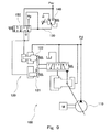
- Patent Document 1 discloses a hydraulic system 100 as shown in FIG.
- the tilt angle of the variable displacement pump 110 is adjusted by the regulator 120.
- the regulator 120 includes a flow control piston 121 and a horsepower control piston 122, and the tilt angle of the pump 110 increases as the control pressure acting on the flow control piston 121 increases or the pump discharge pressure acting on the horsepower control piston 122 decreases. (Discharge flow rate) is increased.
- the regulator 120 is configured so that the one that restricts the discharge flow rate of the flow control piston 121 and the horsepower control piston 122 to a smaller value functions preferentially.
- the regulator 120 is connected to the electromagnetic proportional valve 140 by the secondary pressure line 130.
- the electromagnetic proportional valve 140 outputs a higher secondary pressure to the regulator 120 as the control pressure described above as the operation amount of the pilot operation valve, which is an operation device (not shown), increases.
- the secondary pressure line 130 is provided with a pilot-type switching valve 150.
- the switching valve 150 When the solenoid proportional valve 140 is normal, the switching valve 150 is positioned at the operating position (right side position in FIG. 9) by the secondary pressure of the solenoid proportional valve 140, and the secondary pressure of the solenoid proportional valve 140 is changed to the flow control piston. 121 is applied.
- the switching valve 150 is switched to the neutral position (left side position in FIG. 9), and the pilot operated valve Is applied to the flow control piston 121. Thereby, even if the electromagnetic proportional valve 140 does not function normally, the discharge flow rate of the pump 110 can be increased according to the operation amount of the pilot operation valve.
- the switching valve 150 causes the primary pressure of the electromagnetic proportional valve 140 to act on the horsepower control piston 122, so that a power shift is superimposed on the horsepower control. Therefore, the horsepower control works more strongly than when the electromagnetic proportional valve 140 works normally, thereby lowering the upper limit of the discharge flow rate of the pump 110 for each discharge pressure.
- the regulator 120 requires two pressure receiving chambers for the flow rate control piston 121 and the horsepower control piston 122, and the structure is complicated.
- the present invention secures a pump discharge flow to some extent with a simple structure even when the electromagnetic proportional valve that outputs the secondary pressure as the control pressure to the regulator does not function normally and the secondary pressure becomes zero. It is an object to provide a hydraulic system that can do this.
- a hydraulic system includes an operation device that outputs an operation signal corresponding to an operation amount for an operation unit, a variable displacement main pump, and a flow control piston, and the flow control piston
- a regulator that increases the tilt angle of the main pump as the control pressure acting on the valve increases, a sub pump, and a secondary pressure line connected to the regulator and a primary pressure line connected to the sub pump, and the operation
- An emergency in which an electromagnetic proportional valve that outputs higher secondary pressure as the control pressure to the regulator as the operation signal output from the device increases, and a pair of throttles that branch from the primary pressure line and connect to the tank And the secondary pressure line are divided into a first flow path on the electromagnetic proportional valve side and a second flow path on the regulator side, and A switching valve provided to always divide the line into an upstream flow path and a downstream flow path between the pair of throttles, and blocks the first flow path in the neutral position and When the secondary pressure of the electromagnetic proportional valve exceeds a set value, the first flow path is
- a switching valve that is switched to an operating position that blocks the upstream flow path and the downstream flow path, and two between a minimum value and a maximum value that are larger than the set value in accordance with an operation signal output from the operation device.
- a control device that supplies a command current to the electromagnetic proportional valve so that the electromagnetic proportional valve outputs a secondary pressure.
- the switching valve when the electromagnetic proportional valve is normal, the switching valve is located at the operating position, so the secondary pressure of the electromagnetic proportional valve acts on the flow control piston of the regulator through the secondary pressure line. For this reason, the tilt angle (discharge flow rate) of the pump can be controlled by the electromagnetic proportional valve.
- the electromagnetic proportional valve when the electromagnetic proportional valve does not function normally and its secondary pressure becomes zero, the switching valve is switched to the neutral position, and hydraulic oil flows from the sub pump to the tank through the emergency line. Thereby, the intermediate pressure between the pair of throttles in the emergency line acts on the flow rate control piston of the regulator through the second flow path of the secondary pressure line.
- the emergency line passing through the switching valve may be relatively short, and the regulator does not require a conventional horsepower control piston and only needs a pressure receiving chamber for the flow control piston. The above effect can be obtained by the structure.
- the hydraulic system further includes an engine controlled by the control device that drives the main pump and the sub pump, and the control device is configured to monitor the electromagnetic proportionality from monitoring of a command current supplied to the electromagnetic proportional valve.
- the engine speed may be adjusted around the engine speed at which the engine torque is maximum. According to this configuration, the maximum value of the pump torque with respect to the pump discharge pressure when the electromagnetic proportional valve does not function normally can be set to be high to some extent. Therefore, the intermediate pressure between the pair of throttles can be increased to some extent to secure a large pump discharge flow rate when the electromagnetic proportional valve does not function normally.
- the set value is a first set value
- the maximum value of the secondary pressure of the electromagnetic proportional valve according to the operation signal output from the operating device is a second set pressure lower than the discharge pressure of the sub pump.
- the switching valve blocks the first flow path when the secondary pressure of the electromagnetic proportional valve exceeds the second set value, and the downstream flow path and the first flow path are blocked. You may communicate with two flow paths. According to this configuration, even when the electromagnetic proportional valve does not function normally and its secondary pressure becomes equal to the primary pressure, the pump discharge flow rate can be secured to some extent.
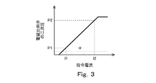
- FIG. 1 is a schematic configuration diagram of a hydraulic system according to a first embodiment of the present invention. It is a graph which shows the relationship between the operation amount with respect to the operation part of an operating device, and the command electric current to an electromagnetic proportional valve. It is a graph which shows the relationship between the command current to an electromagnetic proportional valve, and the secondary pressure of an electromagnetic proportional valve. It is a graph which shows the relationship between the control pressure to a regulator, and the discharge flow rate of the main pump.
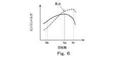
- 5A and 5B are graphs related to the main pump in the modification, FIG. 5A is a graph showing a discharge flow rate restriction line, and FIG. 5B is a graph showing a relationship between pump discharge pressure and pump torque. It is a graph which shows the relationship between an engine speed and an engine torque.
- FIG. 1 shows a hydraulic system 1A according to the first embodiment of the present invention.
- the hydraulic system 1A is mounted on, for example, a construction machine such as a hydraulic excavator or a hydraulic crane, a civil engineering machine, an agricultural machine, or an industrial machine.
- the hydraulic system 1 ⁇ / b> A includes a hydraulic actuator 24 and a main pump 22 that supplies hydraulic oil to the hydraulic actuator 24 via the control valve 3.
- a hydraulic actuator 24 and a main pump 22 that supplies hydraulic oil to the hydraulic actuator 24 via the control valve 3.
- the main pump 22 is driven by the engine 21.
- the engine 21 also drives the sub pump 23.
- the main pump 22 is a variable displacement pump whose tilt angle can be changed.
- the main pump 22 is a swash plate pump.
- the main pump 22 may be an oblique axis pump.
- the tilt angle of the main pump 22 is adjusted by the regulator 5.
- the main pump 22 is connected to the control valve 3 by the supply line 11.
- the discharge pressure of the main pump 22 is kept below the relief pressure by the relief valve 12.
- the hydraulic actuator 24 is a double-acting cylinder, and the control valve 3 is connected to the hydraulic actuator 24 by a pair of supply / discharge lines 31.
- the hydraulic actuator 24 may be a single-acting cylinder, and the control valve 3 may be connected to the hydraulic actuator 24 by a single supply / discharge line 31.
- the hydraulic actuator 24 may be a hydraulic motor.
- the control valve 3 is moved from the neutral position to the first position (position where the hydraulic actuator 24 is operated in one direction) or the second position (position where the hydraulic actuator 24 is operated in the reverse direction) by operating the operation device 4. Can be switched.
- the control valve 3 is a hydraulic pilot type and has a pair of pilot ports.
- the control valve 3 may be an electromagnetic pilot type.
- the operation device 4 includes an operation unit 41 and outputs an operation signal corresponding to an operation amount with respect to the operation unit 41. That is, the operation signal output from the controller device 4 increases as the operation amount increases.
- the operation unit 41 is, for example, an operation lever, but may be a foot pedal or the like.
- the operation device 4 is a pilot operation valve that outputs a pilot pressure as an operation signal.
- the operating device 4 is connected to the pilot port of the control valve 3 by a pair of pilot lines 42.
- the controller device 4 may be an electric joystick that outputs an electrical signal as an operation signal.
- each pilot port of the control valve 3 is connected to the secondary pressure port of the electromagnetic proportional valve.
- the regulator 5 described above includes the flow control piston 56, and increases the tilt angle of the main pump 22 as the control pressure Pc acting on the flow control piston 56 increases.
- the regulator 5 is connected to the secondary pressure port of the electromagnetic proportional valve 61 by the secondary pressure line 62, and the primary pressure port of the electromagnetic proportional valve 61 is connected to the sub pump 23 by the primary pressure line 65.
- the discharge pressure of the sub pump 23 is maintained at the relief set pressure by the relief valve 13.
- the regulator 5 includes a servo piston 51 that changes the tilt angle of the main pump 22 and an adjustment valve 53 that drives the servo piston 51.
- the regulator 5 is formed with a first pressure receiving chamber 5a into which the discharge pressure of the main pump 22 is introduced and a second pressure receiving chamber 5b into which the control pressure is introduced.
- the servo piston 51 has a first end and a second end having a larger diameter than the first end. The first end is exposed to the first pressure receiving chamber 5a, and the second end is exposed to the second pressure receiving chamber 5b.
- the adjusting valve 53 is for adjusting the control pressure introduced into the second pressure receiving chamber 5b.
- the adjusting valve 53 includes a spool 54 that moves in a direction in which the control pressure is reduced (flow rate increasing direction, leftward in FIG. 1) and a direction in which the control pressure is increased (flowrate decreasing direction, rightward in FIG. 1), A sleeve 55 is received.
- the spool 54 is pressed by the above-described flow rate control piston 56 and moves in the flow rate increasing direction, and is moved in the flow rate decreasing direction by the urging force of the spring 57 disposed on the opposite side of the flow rate control piston 56.
- the servo piston 51 is connected to the swash plate 22a of the main pump 22 so as to be movable in the axial direction of the servo piston 51.
- the sleeve 55 is connected to the servo piston 51 by a feedback lever 52 so as to be movable in the axial direction of the servo piston 51.
- the sleeve 55 is formed with a pump port, a tank port, and an output port (the output port communicates with the second pressure receiving chamber 5b), and the output port is determined by the relative position between the sleeve 55 and the spool 54. Either the port is shut off, or the output port communicates with either the pump port or the tank port.
- the regulator 5 is formed with a working chamber 5c that applies a control pressure Pc to the flow control piston 56. That is, the flow rate control piston 56 moves the spool 54 in the direction of increasing the flow rate as the control pressure Pc increases.
- the secondary pressure line 62 extending from the electromagnetic proportional valve 61 described above is connected to the working chamber 5c.
- the electromagnetic proportional valve 61 is a direct proportional type in which the command current supplied to the electromagnetic proportional valve 61 and the secondary pressure output by the electromagnetic proportional valve 61 have a positive correlation.
- the electromagnetic proportional valve 61 is controlled by the control device 9.
- control device 9 also controls the engine 21. Specifically, the control device 9 outputs a command to the engine control device of the engine 21 so as to keep the rotation speed of the engine 21 at a predetermined value.
- control device 9 has a memory such as ROM and RAM and a CPU, and a program stored in the ROM is executed by the CPU.
- the control device 9 may be a single device or may be divided into a plurality of devices (for example, a pump control device and an engine control device).
- the control device 9 is electrically connected to a pressure sensor 91 provided in each of the pair of pilot lines 42 described above. However, in FIG. 1, only a part of the signal lines is drawn for simplification of the drawing.
- the pressure sensor 91 detects the pilot pressure output from the operating device 4.
- the control device 9 increases the command current supplied to the electromagnetic proportional valve 61 as the pilot pressure output from the operation device 4 increases. That is, the electromagnetic proportional valve 61 outputs a higher secondary pressure to the regulator 5 as the control pressure Pc described above as the pilot pressure (operation signal) output from the operation device 4 increases. Thereby, the discharge flow rate of the main pump 22 increases as the operation amount with respect to the operation unit 41 of the operation device 4 increases.
- the control device 9 sets the command current supplied to the electromagnetic proportional valve 61 to a minimum value I1 slightly higher than zero according to the pilot pressure output from the operation device 4. It is changed between the maximum value I2. For this reason, the secondary pressure of the electromagnetic proportional valve 61 also changes between a minimum value P1 and a maximum value P2 greater than zero, as shown in FIG. That is, the electromagnetic proportional valve 61 outputs a secondary pressure between the minimum value P1 and the maximum value P2 in accordance with the operation signal output from the operation device 4.
- the discharge flow rate of the main pump 22 is minimum and is output from at least the electromagnetic proportional valve 61.
- the secondary pressure is the maximum value P2
- the discharge flow rate of the main pump 2 is maximum.
- the range in which the discharge flow rate of the main pump 22 is kept to the minimum does not necessarily need to coincide with the range in which the control pressure Pc is zero to the minimum value P1, and may be narrower than that range.
- the range in which the discharge flow rate of the main pump 22 is maintained at the maximum is not necessarily equal to the range in which the control pressure Pc is equal to or greater than the maximum value P2, and may be narrower than that range.
- the emergency line 71 branches off from the primary pressure line 65 between the electromagnetic proportional valve 61 and the sub pump 23, and this emergency line 71 is connected to the tank.
- the emergency line 71 is provided with a pair of stops 74 and 75.
- a switching valve 8A is provided in the secondary pressure line 62 and the emergency line 71 between the electromagnetic proportional valve 61 and the regulator 5.
- the switching valve 8A divides the secondary pressure line 62 into a first flow path 64 on the electromagnetic proportional valve 61 side and a second flow path 63 on the regulator 5 side, and the emergency line 71 of the pair of throttles 74 and 75. It is provided so as to be divided into an upstream flow path 72 and a downstream flow path 73.
- the switching valve 8A is a pilot type that operates in accordance with the secondary pressure of the electromagnetic proportional valve 61. In the neutral position (left side position in FIG. 1), the switching valve 8A blocks the first flow path 64 of the secondary pressure line 62 and the upstream flow path 72 of the emergency line 71 as well as the downstream flow path 73 and the secondary flow path.
- the pressure line 62 communicates with the second flow path 63.
- the switching valve 8A When the secondary pressure of the electromagnetic proportional valve 61 exceeds the set value ⁇ , the switching valve 8A is switched to the operating position (right side position in FIG. 1) by the secondary pressure. In the operating position, the switching valve 8 ⁇ / b> A communicates the first flow path 64 of the secondary pressure line 62 with the second flow path 63 and blocks the upstream flow path 72 and the downstream flow path 73 of the emergency line 71.
- the set value ⁇ is set smaller than the minimum value P1 of the secondary pressure of the electromagnetic proportional valve 61 corresponding to the pilot pressure output from the operating device 4 as shown in FIG. That is, when the electromagnetic proportional valve 61 is normal, the switching valve 8A is located at the operating position.
- the switching valve 8 ⁇ / b> A when the electromagnetic proportional valve 61 is normal, the switching valve 8 ⁇ / b> A is located at the operating position, so the secondary pressure of the electromagnetic proportional valve 61 is changed to the secondary pressure line 62. Through the flow control piston 56 of the regulator 5. For this reason, the tilt angle (discharge flow rate) of the pump can be controlled by the electromagnetic proportional valve 61.
- the switching valve 8A when the electromagnetic proportional valve 61 does not function normally and its secondary pressure becomes zero, the switching valve 8A is switched to the neutral position, and hydraulic oil is supplied from the sub pump 23 to the tank through the emergency line 71. Flowing.
- the intermediate pressure Pm between the pair of throttles 74 and 75 in the emergency line 71 acts on the flow rate control piston 56 of the regulator 5 through the second flow path 63 of the secondary pressure line 62.
- the discharge flow rate of the main pump 22 can be ensured to some extent (Qm in FIG. 4).
- the emergency line 71 passing through the switching valve 8A may be relatively short, and the regulator 5 does not require a conventional horsepower control piston and only has a working chamber 5c for the flow control piston 56. Therefore, the above effect can be obtained with a simple structure. Thereby, the regulator 5 can be made smaller than before, and the cost can be reduced more than before.
- the control device 9 can determine whether or not the electromagnetic proportional valve 61 functions normally from monitoring of the command current supplied to the electromagnetic proportional valve 61.
- the electromagnetic proportional valve 61 does not function normally, when the electromagnetic proportional valve 61 itself fails (disconnected), or when the electrical wiring extending to the electromagnetic proportional valve 61 is disconnected, the control device 9 or the electromagnetic proportional valve 61 This is the case when the connector has a poor contact (non-energized).
- the control device 9 does not need to change the rotational speed of the engine 21.
- the rotation speed of the engine 21 is set near the rotation speed Na at which the engine torque becomes maximum (for example, Na It may be adjusted within a range of ⁇ 20%. This modification can also be applied to a second embodiment described later.
- a selection switch for selecting the number of rotations of the engine 21 that is kept constant by the control device 9 from a plurality of values may be provided. For this reason, when the electromagnetic proportional valve 61 does not function normally, the rotational speed of the engine 21 may be near the rated rotational speed Nr or may be a considerably low rotational speed Nb.
- the main pump 22 has a discharge flow rate restriction line so that the pump torque of the main pump 22 does not exceed the engine torque.
- the discharge flow rate restriction line is the highest when the engine torque is maximum as shown by the solid line in FIG. 5A, and if the engine torque is low, the discharge flow rate restriction line is correspondingly increased as shown by the one-dot chain line in FIG. 5A. Lower. Accordingly, when the rotation speed of the engine 21 is not changed when the electromagnetic proportional valve 61 does not function normally, the discharge flow rate when the conditions are the most severe as shown by the two-dot chain line in FIG. 5A. In order to match the minimum value of the limit line, the maximum value of the pump torque with respect to the pump discharge pressure must be set very low as shown by the two-dot chain line in FIG. 5B.
- the maximum value of the pump torque with respect to the pump discharge pressure when the electromagnetic proportional valve 61 does not function normally can be set to be high to some extent. Accordingly, the intermediate pressure Pm between the pair of throttles 74 and 75 is increased to some extent to secure a large pump discharge flow rate when the electromagnetic proportional valve 61 does not function normally, as indicated by a broken line in FIG. 5A. Can do.
- FIG. 5 shows a hydraulic system 1B according to the second embodiment of the present invention.
- the same components as those in the first embodiment are denoted by the same reference numerals, and a duplicate description is omitted.
- the switching valve 8A that is a two-position valve is employed, but in this embodiment, the switching valve 8B that is a three-position valve is employed.
- Other configurations in the second embodiment are the same as those in the first embodiment.
- the switching valve 8B is switched between a neutral position (left side position in FIG. 7) and an operating position (center position in FIG. 7) similarly to the switching valve 8A of the first embodiment. That is, the switching valve 8B is switched from the neutral position to the operating position when the secondary pressure of the electromagnetic proportional valve 61 exceeds the set value ⁇ (corresponding to the first set value of the present invention).
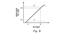
- the switching valve 8B when the secondary pressure of the electromagnetic proportional valve 61 exceeds the set value ⁇ (corresponding to the second set value of the present invention), the switching valve 8B is brought to the limit position (the right position in FIG. 7). Can be switched.
- the set value ⁇ is equal to or greater than the maximum value P2 of the secondary pressure of the electromagnetic proportional valve 61 corresponding to the pilot pressure (operation signal) output from the operation device 4, and Lower than discharge pressure.
- the switching valve 8B blocks the first flow path 64 of the secondary pressure line 62 and the upstream flow path 72 of the emergency line 71 as well as the downstream flow path 73 and the secondary pressure, as in the neutral position. It communicates with the second flow path 63 of the line 62.
- the same effect as in the first embodiment can be obtained. Furthermore, in this embodiment, even when the electromagnetic proportional valve 61 does not function normally and its secondary pressure becomes equal to the primary pressure, the switching valve 8B is switched to the limit position that performs the same function as the neutral position. The discharge flow rate of the main pump 22 can be secured to some extent.
- the pair of throttles 74 and 75 may be built in the switching valve (8A or 8B). Further, the switching valve (8A or 8B) and the electromagnetic proportional valve 61 may be incorporated in the regulator 5.
Landscapes
- Engineering & Computer Science (AREA)
- General Engineering & Computer Science (AREA)
- Physics & Mathematics (AREA)
- Fluid Mechanics (AREA)
- Mechanical Engineering (AREA)
- Fluid-Pressure Circuits (AREA)
- Analytical Chemistry (AREA)
- Chemical & Material Sciences (AREA)
- Mining & Mineral Resources (AREA)
- Civil Engineering (AREA)
- Structural Engineering (AREA)
- Operation Control Of Excavators (AREA)
- Control Of Positive-Displacement Pumps (AREA)
Abstract
油圧システムは、二次圧ラインによりレギュレータと接続されるとともに一次圧ラインにより副ポンプと接続された電磁比例弁と、一次圧ラインから分岐してタンクへつながる、一対の絞りが設けられた非常時ラインと、二次圧ラインを第1流路と第2流路とに分断するとともに、非常時ラインを一対の絞りの間で上流流路と下流流路とに分断するように設けられた、電磁比例弁の二次圧が設定値を上回ったときに中立位置から作動位置に切り換えられる切換弁と、操作装置から出力される操作信号に応じて、設定値よりも大きな最小値と最大値の間の二次圧を電磁比例弁が出力するように、電磁比例弁へ指令電流を送給する制御装置と、を備える。
Description
本発明は、電気ポジコン方式の油圧システムに関する。
従来から、建設機械や産業機械などでは、電気ポジコン方式の油圧システムが採用されている。例えば、特許文献1には、図9に示すような油圧システム100が開示されている。
この油圧システム100では、可変容量型のポンプ110の傾転角がレギュレータ120により調整される。レギュレータ120は、流量制御ピストン121と馬力制御ピストン122を含み、流量制御ピストン121に作用する制御圧が高くなるほど、または馬力制御ピストン122に作用するポンプ吐出圧が低くなるほど、ポンプ110の傾転角(吐出流量)を増大させる。なお、レギュレータ120は、流量制御ピストン121と馬力制御ピストン122のうちの吐出流量を小さく制限する方が優先して機能するように構成される。
レギュレータ120は、二次圧ライン130により電磁比例弁140と接続されている。電磁比例弁140は、図略の操作装置であるパイロット操作弁の操作量が大きくなるほど高い二次圧を上述した制御圧としてレギュレータ120へ出力する。
二次圧ライン130には、パイロット式の切換弁150が設けられている。電磁比例弁140が正常な場合には、切換弁150は、電磁比例弁140の二次圧によって作動位置(図9の右側位置)に位置し、電磁比例弁140の二次圧を流量制御ピストン121に作用させる。一方、電磁比例弁140が故障などにより正常に機能せずにその二次圧がゼロとなった場合には、切換弁150は、中立位置(図9の左側位置)に切り換わり、パイロット操作弁から出力されるパイロット圧を流量制御ピストン121に作用させる。これにより、電磁比例弁140が正常に機能しなくても、ポンプ110の吐出流量をパイロット操作弁の操作量に応じて増加することができる。
ただし、電磁比例弁140が正常に機能しないときには、切換弁150が、電磁比例弁140の一次圧を馬力制御ピストン122に作用させるため、馬力制御にパワーシフトが重畳される。よって、馬力制御が、電磁比例弁140が正常に働いている場合に比べて強く働くことにより、各吐出圧に対するポンプ110の吐出流量の上限が低くなる。
しかしながら、図9に示す構成では、ポンプ110から離れた位置(例えば、建設機械では運転室内)に配置されるパイロット操作弁(操作装置)と切換弁150とを接続する比較的に長いラインが必要であるとともに、レギュレータ120に流量制御ピストン121および馬力制御ピストン122用の2つの受圧室が必要であり、構造が複雑である。
そこで、本発明は、レギュレータへ制御圧として二次圧を出力する電磁比例弁が正常に機能せずにその二次圧がゼロとなった場合でも、簡易な構造でポンプの吐出流量をある程度確保することができる油圧システムを提供することを目的とする。
前記課題を解決するために、本発明の油圧システムは、操作部に対する操作量に応じた操作信号を出力する操作装置と、可変容量型の主ポンプと、流量制御ピストンを含み、前記流量制御ピストンに作用する制御圧が高くなるほど前記主ポンプの傾転角を増大させるレギュレータと、副ポンプと、二次圧ラインにより前記レギュレータと接続されるとともに一次圧ラインにより前記副ポンプと接続され、前記操作装置から出力される操作信号が大きくなるほど高い二次圧を前記制御圧として前記レギュレータへ出力する電磁比例弁と、前記一次圧ラインから分岐してタンクへつながる、一対の絞りが設けられた非常時ラインと、前記二次圧ラインを前記電磁比例弁側の第1流路と前記レギュレータ側の第2流路とに分断するとともに、前記非常時ラインを前記一対の絞りの間で上流流路と下流流路とに分断するように設けられた切換弁であって、中立位置では前記第1流路をブロックするとともに前記上流流路を前記下流流路および前記第2流路と連通し、前記電磁比例弁の二次圧が設定値を上回ったときに、当該二次圧によって、前記第1流路を前記第2流路と連通するとともに前記上流流路および前記下流流路をブロックする作動位置に切り換えられる切換弁と、前記操作装置から出力される操作信号に応じて、前記設定値よりも大きな最小値と最大値の間の二次圧を前記電磁比例弁が出力するように、前記電磁比例弁へ指令電流を送給する制御装置と、を備える、ことを特徴とする。
上記の構成によれば、電磁比例弁が正常な場合は、切換弁が作動位置に位置するため、電磁比例弁の二次圧が二次圧ラインを通じてレギュレータの流量制御ピストンに作用する。このため、電磁比例弁によってポンプの傾転角(吐出流量)を制御することができる。一方、電磁比例弁が正常に機能せずにその二次圧がゼロとなった場合には、切換弁が中立位置に切り換わり、副ポンプからタンクへ非常時ラインを通じて作動油が流れる。これにより、非常時ラインにおける一対の絞りの間の中間圧が二次圧ラインの第2流路を通じてレギュレータの流量制御ピストンに作用する。その結果、ポンプの吐出流量をある程度確保することができる。そして、切換弁を経由する非常時ラインは比較的に短くてよく、かつ、レギュレータには従来のような馬力制御ピストンが不要であって流量制御ピストン用の受圧室さえあればよいため、簡易な構造で上記の効果を得ることができる。
上記の油圧システムは、前記主ポンプおよび前記副ポンプを駆動する、前記制御装置により制御されるエンジンをさらに備え、前記制御装置は、前記電磁比例弁へ送給する指令電流のモニタリングから前記電磁比例弁が正常に機能しないと判定したときに、前記エンジンの回転数をエンジントルクが最大となる回転数付近に調整してもよい。この構成によれば、電磁比例弁が正常に機能しないときのポンプ吐出圧に対するポンプトルクの最大値をある程度高く設定することができる。従って、一対の絞りの間の中間圧をある程度高くして、電磁比例弁が正常に機能しないときのポンプの吐出流量を多く確保することができる。
前記設定値は、第1設定値であり、前記操作装置から出力される操作信号に応じた前記電磁比例弁の二次圧の最大値は、前記副ポンプの吐出圧よりも低い第2設定圧以下であり、前記切換弁は、前記電磁比例弁の二次圧が前記第2設定値を上回ったときに、前記第1流路をブロックするとともに前記上流流路を前記下流流路および前記第2流路と連通してもよい。この構成によれば、電磁比例弁が正常に機能せずにその二次圧が一次圧と等しくなった場合でも、ポンプの吐出流量をある程度確保することができる。
本発明によれば、レギュレータへ制御圧として二次圧を出力する電磁比例弁が正常に機能せずにその二次圧がゼロとなった場合でも、簡易な構造でポンプの吐出流量をある程度確保することができる。
(第1実施形態)
図1に、本発明の第1実施形態に係る油圧システム1Aを示す。油圧システム1Aは、例えば、油圧ショベルや油圧クレーンのような建設機械、土木機械、農業機械または産業機械に搭載される。
図1に、本発明の第1実施形態に係る油圧システム1Aを示す。油圧システム1Aは、例えば、油圧ショベルや油圧クレーンのような建設機械、土木機械、農業機械または産業機械に搭載される。
具体的に、油圧システム1Aは、油圧アクチュエータ24と、油圧アクチュエータ24に制御弁3を介して作動油を供給する主ポンプ22を含む。図例では、油圧アクチュエータ24と制御弁3のセットが1つであるが、油圧アクチュエータ24と制御弁3のセットは複数設けられてもよい。
主ポンプ22は、エンジン21により駆動される。エンジン21は、副ポンプ23も駆動する。
主ポンプ22は、傾転角が変更可能な、可変容量型のポンプである。本実施形態では、主ポンプ22が斜板ポンプである。ただし、主ポンプ22は、斜軸ポンプであってもよい。主ポンプ22の傾転角は、レギュレータ5により調整される。
主ポンプ22は、供給ライン11により制御弁3と接続されている。主ポンプ22の吐出圧は、リリーフ弁12によってリリーフ圧以下に保たれる。
本実施形態では、油圧アクチュエータ24が複動シリンダであり、制御弁3が一対の給排ライン31により油圧アクチュエータ24と接続されている。ただし、油圧アクチュエータ24が単動シリンダであり、制御弁3が1本の給排ライン31により油圧アクチュエータ24と接続されてもよい。あるいは、油圧アクチュエータ24は、油圧モータであってもよい。
制御弁3は、操作装置4が操作されることによって、中立位置から第1位置(油圧アクチュエータ24を一方向に作動させる位置)または第2位置(油圧アクチュエータ24を逆方向に作動させる位置)に切り換えられる。本実施形態では、制御弁3が油圧パイロット式であり、一対のパイロットポートを有する。ただし、制御弁3は、電磁パイロット式であってもよい。
操作装置4は、操作部41を有し、操作部41に対する操作量に応じた操作信号を出力する。つまり、操作装置4から出力される操作信号は、操作量が大きくなるほど大きくなる。操作部41は、例えば操作レバーであるが、フットペダルなどであってもよい。
本実施形態では、操作装置4が、操作信号としてパイロット圧を出力するパイロット操作弁である。このため、操作装置4が一対のパイロットライン42により制御弁3のパイロットポートと接続されている。そして、操作装置4から出力されるパイロット圧(操作信号)が大きくなるほど、制御弁3が油圧アクチュエータ24へ作動油を供給する通路の開口面積を増大させる。ただし、操作装置4は、操作信号として電気信号を出力する電気ジョイスティックであってもよい。この場合、制御弁3の各パイロットポートは、電磁比例弁の二次圧ポートと接続される。
上述したレギュレータ5は、流量制御ピストン56を含み、流量制御ピストン56に作用する制御圧Pcが高くなるほど主ポンプ22の傾転角を増大させる。レギュレータ5は、二次圧ライン62により電磁比例弁61の二次圧ポートと接続されており、電磁比例弁61の一次圧ポートは、一次圧ライン65により副ポンプ23と接続されている。副ポンプ23の吐出圧は、リリーフ弁13によってリリーフ設定圧に維持される。
レギュレータ5は、より詳しくは、主ポンプ22の傾転角を変更するサーボピストン51と、サーボピストン51を駆動するための調整弁53を含む。レギュレータ5には、主ポンプ22の吐出圧が導入される第1受圧室5aと、制御圧が導入される第2受圧室5bが形成されている。サーボピストン51は、第1端部と、第1端部よりも大径の第2端部を有している。第1端部は第1受圧室5aに露出しており、第2端部は第2受圧室5bに露出している。
調整弁53は、第2受圧室5bに導入される制御圧を調整するためのものである。具体的に、調整弁53は、制御圧を低下させる方向(流量増加方向、図1では左向き)および制御圧を上昇させる方向(流量減少方向、図1では右向き)に移動するスプール54と、スプール54を収容するスリーブ55を含む。スプール54は、上述した流量制御ピストン56に押圧されて流量増加方向に移動し、流量制御ピストン56と反対側に配置されたスプリング57の付勢力によって流量減少方向に移動する。
サーボピストン51は、当該サーボピストン51の軸方向に移動可能となるように主ポンプ22の斜板22aと連結されている。スリーブ55は、サーボピストン51の軸方向に移動可能となるようにフィードバックレバー52によりサーボピストン51と連結されている。スリーブ55には、ポンプポート、タンクポートおよび出力ポート(出力ポートは第2受圧室5bと連通する)が形成されており、スリーブ55とスプール54との相対位置によって、出力ポートがポンプポートおよびタンクポートの双方から遮断されるか、出力ポートがポンプポートおよびタンクポートのどちらかと連通される。そして、スプール54が流量制御ピストン56によって流量増加方向または流量減少方向に移動すると、サーボピストン51の両側から作用する力(圧力×サーボピストン受圧面積)が釣り合うようにスプール54とスリーブ55との相対位置が定まり、制御圧が調整される。
さらに、レギュレータ5には、流量制御ピストン56に制御圧Pcを作用させる作動室5cが形成されている。つまり、流量制御ピストン56は、制御圧Pcが高くなるほどスプール54を流量増加方向に移動させる。上述した電磁比例弁61から延びる二次圧ライン62は、作動室5cへつながっている。
電磁比例弁61は、図3に示すように、当該電磁比例弁61に送給される指令電流と当該電磁比例弁61が出力する二次圧とが正の相関を示す正比例型である。電磁比例弁61は、制御装置9により制御される。
また、制御装置9は、エンジン21も制御する。具体的に、制御装置9は、エンジン21の回転数を所定の値に保つようにエンジン21のエンジン制御装置へ指令を出力する。
例えば、制御装置9は、ROMやRAMなどのメモリとCPUを有し、ROMに格納されたプログラムがCPUにより実行される。制御装置9は、単一の機器であってもよいし、複数の機器(例えば、ポンプ制御装置とエンジン制御装置)に分割されてもよい。
制御装置9は、上述した一対のパイロットライン42のそれぞれに設けられた圧力センサ91と電気的に接続されている。ただし、図1では、図面の簡略化のために一部の信号線のみを描いている。
圧力センサ91は、操作装置4から出力されるパイロット圧を検出する。そして、制御装置9は、図2に示すように、操作装置4から出力されるパイロット圧が大きくなるほど電磁比例弁61へ送給する指令電流を大きくする。つまり、電磁比例弁61は、操作装置4から出力されるパイロット圧(操作信号)が大きくなるほど高い二次圧を上述した制御圧Pcとしてレギュレータ5へ出力する。これにより、操作装置4の操作部41に対する操作量が大きくなるほど主ポンプ22の吐出流量が増加する。
より詳しくは、制御装置9は、図2に示すように、操作装置4から出力されるパイロット圧に応じて、電磁比例弁61へ送給する指令電流をゼロより少し高目の最小値I1と最大値I2との間で変化させる。このため、電磁比例弁61の二次圧も、図3に示すように、ゼロよりも大きな最小値P1と最大値P2の間で変化する。つまり、電磁比例弁61は、操作装置4から出力される操作信号に応じて、最小値P1と最大値P2の間の二次圧を出力する。
本実施形態では、図4に示すように、少なくとも電磁比例弁61から出力される二次圧が最小値P1のときに主ポンプ22の吐出流量が最小となり、少なくとも電磁比例弁61から出力される二次圧が最大値P2のときに主ポンプ2の吐出流量が最大となる。ただし、主ポンプ22の吐出流量が最小に維持される範囲は、必ずしも制御圧Pcがゼロから最小値P1までの範囲と一致する必要はなく、その範囲よりも狭くてもよい。同様に、主ポンプ22の吐出流量が最大に維持される範囲は、必ずしも制御圧Pcが最大値P2以上の範囲と一致する必要はなく、その範囲よりも狭くてもよい。
電磁比例弁61と副ポンプ23の間の一次圧ライン65からは非常時ライン71が分岐しており、この非常時ライン71はタンクへつながっている。非常時ライン71には、一対の絞り74,75が設けられている。
電磁比例弁61とレギュレータ5の間の二次圧ライン62および非常時ライン71には、切換弁8Aが設けられている。切換弁8Aは、二次圧ライン62を電磁比例弁61側の第1流路64とレギュレータ5側の第2流路63とに分断するとともに、非常時ライン71を一対の絞り74,75の間で上流流路72と下流流路73とに分断するように設けられている。
切換弁8Aは、電磁比例弁61の二次圧に応じて作動するパイロット式である。切換弁8Aは、中立位置(図1の左側位置)では、二次圧ライン62の第1流路64をブロックするとともに、非常時ライン71の上流流路72をその下流流路73および二次圧ライン62の第2流路63と連通する。
切換弁8Aは、電磁比例弁61の二次圧が設定値αを上回ったときに、当該二次圧によって作動位置(図1の右側位置)に切り換えられる。作動位置では、切換弁8Aは、二次圧ライン62の第1流路64をその第2流路63と連通するとともに、非常時ライン71の上流流路72および下流流路73をブロックする。
設定値αは、図3に示すように、操作装置4から出力されるパイロット圧に応じた電磁比例弁61の二次圧の最小値P1よりも小さく設定されている。つまり、電磁比例弁61が正常な場合は、切換弁8Aは作動位置に位置する。
以上説明したように、本実施形態の油圧システム1Aでは、電磁比例弁61が正常な場合は、切換弁8Aが作動位置に位置するため、電磁比例弁61の二次圧が二次圧ライン62を通じてレギュレータ5の流量制御ピストン56に作用する。このため、電磁比例弁61によってポンプの傾転角(吐出流量)を制御することができる。一方、電磁比例弁61が正常に機能せずにその二次圧がゼロとなった場合には、切換弁8Aが中立位置に切り換わり、副ポンプ23からタンクへ非常時ライン71を通じて作動油が流れる。これにより、非常時ライン71における一対の絞り74,75の間の中間圧Pmが二次圧ライン62の第2流路63を通じてレギュレータ5の流量制御ピストン56に作用する。その結果、主ポンプ22の吐出流量をある程度(図4中のQm)確保することができる。そして、切換弁8Aを経由する非常時ライン71は比較的に短くてよく、かつ、レギュレータ5には従来のような馬力制御ピストンが不要であって流量制御ピストン56用の作動室5cさえあればよいため、簡易な構造で上記の効果を得ることができる。これにより、レギュレータ5を従来よりも小さくすることができるとともに、コストを従来よりも低減することができる。
<変形例>
制御装置9は、電磁比例弁61へ送給する指令電流のモニタリングから、電磁比例弁61が正常に機能するか否かを判定することができる。ここで、電磁比例弁61が正常に機能しない場合とは、電磁比例弁61自体が故障(断線)した場合、電磁比例弁61まで延びる電気配線が断線した場合、制御装置9または電磁比例弁61のコネクタが接触不良(非通電)を発生した場合などである。制御装置9は、電磁比例弁61が正常に機能しないと判定したときでも、エンジン21の回転数を変更しなくてもよい。しかし、制御装置9は、電磁比例弁61が正常に機能しないと判定したときに、図6に示すように、エンジン21の回転数をエンジントルクが最大となる回転数Na付近(例えば、Naの±20%の範囲内)に調整してもよい。なお、本変形例は、後述する第2実施形態にも適用可能である。
制御装置9は、電磁比例弁61へ送給する指令電流のモニタリングから、電磁比例弁61が正常に機能するか否かを判定することができる。ここで、電磁比例弁61が正常に機能しない場合とは、電磁比例弁61自体が故障(断線)した場合、電磁比例弁61まで延びる電気配線が断線した場合、制御装置9または電磁比例弁61のコネクタが接触不良(非通電)を発生した場合などである。制御装置9は、電磁比例弁61が正常に機能しないと判定したときでも、エンジン21の回転数を変更しなくてもよい。しかし、制御装置9は、電磁比例弁61が正常に機能しないと判定したときに、図6に示すように、エンジン21の回転数をエンジントルクが最大となる回転数Na付近(例えば、Naの±20%の範囲内)に調整してもよい。なお、本変形例は、後述する第2実施形態にも適用可能である。
油圧システム1Aが搭載される機械の種類によっては、制御装置9によって一定に保たれるエンジン21の回転数を複数の値から選択するための選択スイッチが設けられることがある。このため、電磁比例弁61が正常に機能しないときには、エンジン21の回転数が定格回転数Nr付近である場合もあるし、かなり低い回転数Nbである場合もある。
図5Aに示すように、主ポンプ22には、主ポンプ22のポンプトルクがエンジントルクを超えないようにするために吐出流量制限線が定められる。吐出流量制限線は、図5A中に実線で示すようにエンジントルクが最大となるときが最も高く、エンジントルクが低くなれば図5A中に一点鎖線で示すようにその分だけ吐出流量制限線も低くなる。従って、電磁比例弁61が正常に機能しないときにエンジン21の回転数を変更しない場合には、図5A中に二点鎖線で示すように一定となる吐出流量を最も条件が厳しいときの吐出流量制限線の最小値に一致させるために、図5Bに二点鎖線で示すようにポンプ吐出圧に対するポンプトルクの最大値をかなり低く設定しなければならない。
これに対し、本変形例のように、電磁比例弁61が正常に機能しない場合のエンジン21の回転数をエンジントルクが最大となる回転数Na付近に調整すれば、図5B中に破線で示すように、電磁比例弁61が正常に機能しないときのポンプ吐出圧に対するポンプトルクの最大値をある程度高く設定することができる。従って、一対の絞り74,75の間の中間圧Pmをある程度高くして、図5A中に破線で示すように、電磁比例弁61が正常に機能しないときのポンプの吐出流量を多く確保することができる。
(第2実施形態)
図5に、本発明の第2実施形態に係る油圧システム1Bを示す。なお、本実施形態において、第1実施形態と同一構成要素には同一符号を付し、重複した説明は省略する。
図5に、本発明の第2実施形態に係る油圧システム1Bを示す。なお、本実施形態において、第1実施形態と同一構成要素には同一符号を付し、重複した説明は省略する。
第一実施形態では、2位置弁である切換弁8Aが採用されていたが、本実施形態では、3位置弁である切換弁8Bが採用されている。第2実施形態におけるその他の構成は、第1実施形態と同様である。
切換弁8Bは、第1実施形態の切換弁8Aと同様に、中立位置(図7の左側位置)と作動位置(図7の中央位置)との間で切り換えられる。つまり、切換弁8Bは、電磁比例弁61の二次圧が設定値α(本発明の第1設定値に相当)を上回ったときに、中立位置から作動位置に切り換えられる。
さらに、本実施形態では、電磁比例弁61の二次圧が設定値β(本発明の第2設定値に相当)を上回ったときに、切換弁8Bが限界位置(図7の右側位置)に切り換えられる。図8に示すように、設定値βは、操作装置4から出力されるパイロット圧(操作信号)に応じた電磁比例弁61の二次圧の最大値P2以上であり、かつ、副ポンプ23の吐出圧よりも低い。
限界位置では、切換弁8Bは、中立位置と同様に、二次圧ライン62の第1流路64をブロックするとともに、非常時ライン71の上流流路72をその下流流路73および二次圧ライン62の第2流路63と連通する。
本実施形態でも、第1実施形態と同様の効果を得ることができる。さらに、本実施形態では、電磁比例弁61が正常に機能せずにその二次圧が一次圧と等しくなった場合でも、切換弁8Bが中立位置と同様の機能を果たす限界位置に切り換えられるため、主ポンプ22の吐出流量をある程度確保することができる。
(その他の実施形態)
本発明は上述した実施形態に限定されるものではなく、本発明の要旨を逸脱しない範囲で種々の変形が可能である。
本発明は上述した実施形態に限定されるものではなく、本発明の要旨を逸脱しない範囲で種々の変形が可能である。
例えば、一対の絞り74,75は切換弁(8Aまたは8B)に内蔵されてもよい。また、切換弁(8Aまたは8B)および電磁比例弁61は、レギュレータ5に内蔵されてもよい。
1A,1B 油圧システム
21 エンジン
22 主ポンプ
23 副ポンプ
4 操作装置
41 操作部
5 レギュレータ
56 流量制御ピストン
61 電磁比例弁
62 二次圧ライン
63 第2流路
64 第1流路
65 一次圧ライン
71 非常時ライン
72 上流流路
73 下流流路
74,75 絞り
8A,8B 切換弁
9 制御装置
21 エンジン
22 主ポンプ
23 副ポンプ
4 操作装置
41 操作部
5 レギュレータ
56 流量制御ピストン
61 電磁比例弁
62 二次圧ライン
63 第2流路
64 第1流路
65 一次圧ライン
71 非常時ライン
72 上流流路
73 下流流路
74,75 絞り
8A,8B 切換弁
9 制御装置
Claims (3)
- 操作部に対する操作量に応じた操作信号を出力する操作装置と、
可変容量型の主ポンプと、
流量制御ピストンを含み、前記流量制御ピストンに作用する制御圧が高くなるほど前記主ポンプの傾転角を増大させるレギュレータと、
副ポンプと、
二次圧ラインにより前記レギュレータと接続されるとともに一次圧ラインにより前記副ポンプと接続され、前記操作装置から出力される操作信号が大きくなるほど高い二次圧を前記制御圧として前記レギュレータへ出力する電磁比例弁と、
前記一次圧ラインから分岐してタンクへつながる、一対の絞りが設けられた非常時ラインと、
前記二次圧ラインを前記電磁比例弁側の第1流路と前記レギュレータ側の第2流路とに分断するとともに、前記非常時ラインを前記一対の絞りの間で上流流路と下流流路とに分断するように設けられた切換弁であって、中立位置では前記第1流路をブロックするとともに前記上流流路を前記下流流路および前記第2流路と連通し、前記電磁比例弁の二次圧が設定値を上回ったときに、当該二次圧によって、前記第1流路を前記第2流路と連通するとともに前記上流流路および前記下流流路をブロックする作動位置に切り換えられる切換弁と、
前記操作装置から出力される操作信号に応じて、前記設定値よりも大きな最小値と最大値の間の二次圧を前記電磁比例弁が出力するように、前記電磁比例弁へ指令電流を送給する制御装置と、
を備える、油圧システム。 - 前記主ポンプおよび前記副ポンプを駆動する、前記制御装置により制御されるエンジンをさらに備え、
前記制御装置は、前記電磁比例弁へ送給する指令電流のモニタリングから前記電磁比例弁が正常に機能しないと判定したときに、前記エンジンの回転数をエンジントルクが最大となる回転数付近に調整する、請求項1に記載の油圧システム。 - 前記設定値は、第1設定値であり、
前記操作装置から出力される操作信号に応じた前記電磁比例弁の二次圧の最大値は、前記副ポンプの吐出圧よりも低い第2設定圧以下であり、
前記切換弁は、前記電磁比例弁の二次圧が前記第2設定値を上回ったときに、前記第1流路をブロックするとともに前記上流流路を前記下流流路および前記第2流路と連通する、請求項1または2に記載の油圧システム。
Priority Applications (1)
| Application Number | Priority Date | Filing Date | Title |
|---|---|---|---|
| CN201880020464.5A CN110431317B (zh) | 2017-04-18 | 2018-04-18 | 油压系统 |
Applications Claiming Priority (2)
| Application Number | Priority Date | Filing Date | Title |
|---|---|---|---|
| JP2017081847A JP6815267B2 (ja) | 2017-04-18 | 2017-04-18 | 油圧システム |
| JP2017-081847 | 2017-04-18 |
Publications (1)
| Publication Number | Publication Date |
|---|---|
| WO2018194091A1 true WO2018194091A1 (ja) | 2018-10-25 |
Family
ID=63855826
Family Applications (1)
| Application Number | Title | Priority Date | Filing Date |
|---|---|---|---|
| PCT/JP2018/015990 Ceased WO2018194091A1 (ja) | 2017-04-18 | 2018-04-18 | 油圧システム |
Country Status (3)
| Country | Link |
|---|---|
| JP (1) | JP6815267B2 (ja) |
| CN (1) | CN110431317B (ja) |
| WO (1) | WO2018194091A1 (ja) |
Families Citing this family (2)
| Publication number | Priority date | Publication date | Assignee | Title |
|---|---|---|---|---|
| KR102198503B1 (ko) * | 2018-12-19 | 2021-01-05 | 주식회사 모트롤 | 유압 펌프 유량 제어 시스템 |
| JP7412181B2 (ja) | 2020-01-10 | 2024-01-12 | 川崎重工業株式会社 | 油圧ポンプシステム、及び制御装置 |
Citations (2)
| Publication number | Priority date | Publication date | Assignee | Title |
|---|---|---|---|---|
| JP2005265062A (ja) * | 2004-03-18 | 2005-09-29 | Kobelco Contstruction Machinery Ltd | 作業機械の油圧制御装置 |
| JP2013185401A (ja) * | 2012-03-09 | 2013-09-19 | Sumitomo (Shi) Construction Machinery Co Ltd | 建設機械の制御装置及びその制御方法 |
Family Cites Families (4)
| Publication number | Priority date | Publication date | Assignee | Title |
|---|---|---|---|---|
| JPH0756267B2 (ja) * | 1989-12-27 | 1995-06-14 | 油研工業株式会社 | 可変容量型ポンプ |
| KR100641396B1 (ko) * | 2005-09-15 | 2006-11-01 | 볼보 컨스트럭션 이키프먼트 홀딩 스웨덴 에이비 | 유압제어시스템 |
| CN104554432B (zh) * | 2014-05-29 | 2017-04-12 | 四川大学 | 一种工程机械线控转向系统 |
| JP2016169818A (ja) * | 2015-03-13 | 2016-09-23 | 川崎重工業株式会社 | 油圧駆動システム |
-
2017
- 2017-04-18 JP JP2017081847A patent/JP6815267B2/ja active Active
-
2018
- 2018-04-18 CN CN201880020464.5A patent/CN110431317B/zh active Active
- 2018-04-18 WO PCT/JP2018/015990 patent/WO2018194091A1/ja not_active Ceased
Patent Citations (2)
| Publication number | Priority date | Publication date | Assignee | Title |
|---|---|---|---|---|
| JP2005265062A (ja) * | 2004-03-18 | 2005-09-29 | Kobelco Contstruction Machinery Ltd | 作業機械の油圧制御装置 |
| JP2013185401A (ja) * | 2012-03-09 | 2013-09-19 | Sumitomo (Shi) Construction Machinery Co Ltd | 建設機械の制御装置及びその制御方法 |
Also Published As
| Publication number | Publication date |
|---|---|
| CN110431317B (zh) | 2020-08-11 |
| JP6815267B2 (ja) | 2021-01-20 |
| JP2018179199A (ja) | 2018-11-15 |
| CN110431317A (zh) | 2019-11-08 |
Similar Documents
| Publication | Publication Date | Title |
|---|---|---|
| JP6917871B2 (ja) | 建設機械の油圧制御回路 | |
| US10260531B2 (en) | Hydraulic drive system | |
| WO2015064025A1 (ja) | 建設機械の油圧駆動システム | |
| WO2015064026A1 (ja) | 油圧ショベル駆動システム | |
| JP6463649B2 (ja) | 建設機械の油圧駆動システム | |
| JP7324655B2 (ja) | 建設機械の油圧システム | |
| CN113056616B (zh) | 油压驱动系统 | |
| JP6757238B2 (ja) | 油圧駆動システム | |
| US10619632B2 (en) | Hydraulic drive system of construction machine | |
| JP4976920B2 (ja) | ポンプ吐出量制御装置 | |
| JP3625149B2 (ja) | 建設機械の油圧制御回路 | |
| WO2018194091A1 (ja) | 油圧システム | |
| JP6799480B2 (ja) | 油圧システム | |
| WO2018178960A1 (ja) | 油圧システム | |
| JP6940992B2 (ja) | 油圧駆動装置、及びそれを備える油圧駆動システム。 | |
| JP2010048359A (ja) | 建設機械のポンプ制御回路 | |
| JP6698359B2 (ja) | フェールセーフ付油圧システム | |
| EP3434910A1 (en) | Shovel and control valve for shovel | |
| JPH068641B2 (ja) | 油圧回路 | |
| JP5015880B2 (ja) | 建設機械のポンプ制御回路 | |
| WO2019220564A1 (ja) | 油圧システム | |
| JPH109415A (ja) | 流量制御弁付きコントロール弁及び圧力制御弁付きコントロール弁 | |
| WO2018178961A1 (ja) | 油圧システム | |
| WO2013042192A1 (ja) | 建設機械のポンプ吐出量制御回路 | |
| WO2021206002A1 (ja) | 建設機械の油圧システム |
Legal Events
| Date | Code | Title | Description |
|---|---|---|---|
| 121 | Ep: the epo has been informed by wipo that ep was designated in this application |
Ref document number: 18787892 Country of ref document: EP Kind code of ref document: A1 |
|
| NENP | Non-entry into the national phase |
Ref country code: DE |
|
| 122 | Ep: pct application non-entry in european phase |
Ref document number: 18787892 Country of ref document: EP Kind code of ref document: A1 |