WO2018189807A1 - Electric device - Google Patents
Electric device Download PDFInfo
- Publication number
- WO2018189807A1 WO2018189807A1 PCT/JP2017/014817 JP2017014817W WO2018189807A1 WO 2018189807 A1 WO2018189807 A1 WO 2018189807A1 JP 2017014817 W JP2017014817 W JP 2017014817W WO 2018189807 A1 WO2018189807 A1 WO 2018189807A1
- Authority
- WO
- WIPO (PCT)
- Prior art keywords
- door
- box
- hinge
- packing
- electric device
- Prior art date
Links
Images


Classifications
-
- H—ELECTRICITY
- H02—GENERATION; CONVERSION OR DISTRIBUTION OF ELECTRIC POWER
- H02B—BOARDS, SUBSTATIONS OR SWITCHING ARRANGEMENTS FOR THE SUPPLY OR DISTRIBUTION OF ELECTRIC POWER
- H02B1/00—Frameworks, boards, panels, desks, casings; Details of substations or switching arrangements
- H02B1/26—Casings; Parts thereof or accessories therefor
- H02B1/28—Casings; Parts thereof or accessories therefor dustproof, splashproof, drip-proof, waterproof or flameproof
-
- H—ELECTRICITY
- H02—GENERATION; CONVERSION OR DISTRIBUTION OF ELECTRIC POWER
- H02B—BOARDS, SUBSTATIONS OR SWITCHING ARRANGEMENTS FOR THE SUPPLY OR DISTRIBUTION OF ELECTRIC POWER
- H02B1/00—Frameworks, boards, panels, desks, casings; Details of substations or switching arrangements
- H02B1/26—Casings; Parts thereof or accessories therefor
- H02B1/30—Cabinet-type casings; Parts thereof or accessories therefor
- H02B1/38—Hinged covers or doors
Definitions
- the present invention relates to a box body that houses a device main body so as to be removable from a device main body outlet, and an electric device that includes a door that is pivotally attached to the box body by a hinge so as to be opened and closed, and opens and closes the device main body outlet. is there.
- a structure that closes the gap between the door and the box, or a dust-proof packing is attached to the box-side frame or extension member like the closed switchboard of Patent Document 2, and a pedestal is provided on the door side, and the dust-proof packing and the pedestal Is in a structure that closes the gap between the door and the box.
- JP 2014-166122 A Japanese Utility Model Publication No. 4-14404
- the box-side hinge is extended to the height of the door, and the gap between the door and the box is closed by the box-side hinge to prevent foreign solids from entering the switchboard. At this time, it is necessary to secure a gap between the box-side hinge and the door so that the door and the box-side hinge do not interfere with each other.
- the box-side hinge is difficult to manufacture and expensive, but for products that do not have a fixed door height, such as a control center unit, if the door height changes due to changes, etc., the box-side hinge Had to be remanufactured and the cost was high.
- the present invention has been made in view of the above-described circumstances, and a box body that accommodates an apparatus main body so as to be removable from an apparatus main body outlet, and is pivotally attached to the box body by a hinge so as to be openable and closable.
- a hinge so as to be openable and closable.
- An electrical device includes a box that houses a device main body so that the device main body can be removed from the device main body outlet, and an electric door that is pivotally attached to the box body by a hinge so as to be opened and closed. The door opens and closes the device main body outlet.
- An inner end portion is attached to the main frame of the outer wall of the box body, and a tip end portion faces the inner wall surface of the door in a state where the device main body outlet is closed, and at least the axial length of the hinge rotation axis of the hinge
- a sealing frame extending over the door, and a front face of the sealing frame that is interposed between a surface facing the door and the inner wall surface of the door, and at the hinge portion,
- a hinge portion packing is provided to prevent foreign matter outside the box from entering the inside of the box from between the door. Is.
- the present invention is an electric device including a box body that houses a device main body so as to be removable from a device main body outlet, and a door that is pivotally attached to the box body by a hinge so as to be opened and closed and opens and closes the device main body outlet.
- the inner end portion is attached to the main frame of the outer wall of the box body, and the front end portion faces the inner wall surface of the door in a state where the device main body outlet is closed, and at least the axial length of the hinge rotation shaft of the hinge A sealing frame extending across the wall, and the front end of the sealing frame interposed between a surface facing the door and the inner wall surface of the door, and at the hinge portion, the box body And the door are provided with a hinge packing that prevents foreign matter outside the box from entering the inside of the box, so that the box and the door at the hinge portion.
- Embodiment 1 of this invention is a perspective view which shows the state which closed the door of the electric equipment.
- Embodiment 1 of this invention is a cross-sectional plan view in the II line
- Embodiment 1 of this invention is a vertical side view in the II-II line
- Embodiment 1 of this invention is a perspective view which shows the state which opened the door of the electric equipment.
- Embodiment 1 of this invention and is a cross-sectional plan view in the III-III line of FIG.
- Embodiment 1 of this invention It is a figure which shows Embodiment 1 of this invention, and is a vertical side view in the IV-IV line of FIG. It is a figure which shows Embodiment 1 of this invention, and is a perspective view which shows the external shape of the whole for a sealing frame and hinge part packing. It is a figure which shows Embodiment 2 of this invention, and is a cross-sectional plan view equivalent to the cross-sectional plan view in the II line
- FIG. Embodiment 1 of the present invention will be described below with reference to FIGS. 1, 2, 3, 4, 4, 5, 6, and 7.
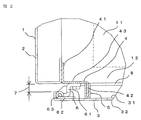
- FIG. 1 is a perspective view showing a state in which the door of the electric device is closed
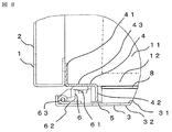
- FIG. 2 is a cross-sectional plan view taken along line II in FIG. 1
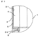
- FIG. 3 is a longitudinal side view taken along line II-II in FIG.
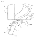
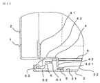
- FIG. 5 is a cross-sectional plan view taken along line III-III in FIG. 4
- FIG. 6 is a longitudinal side view taken along line IV-IV in FIG. 4
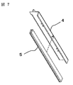
- FIG. 7 is a sealing frame and hinge part packing. It is a perspective view which shows the external shape of the whole.
- the electrical device is used to take out the device body 11 from the box 1 as necessary, such as the box 1 of the electrical device, the device body 11, and maintenance.
- the rotary shaft 63 (the shaft constituting the hinge 6 by pivoting the one piece 61 and the other piece 62), the gap 7 between the box 1 and the door 3, and the peripheral packing 8 This is an example.
- a Z-shaped sealing frame 4 is attached to a main frame 2 that is a vertical frame of the box 1, and one piece of a hinge 6 (a piece on the box side) is attached to the sealing frame 4. 61 and the hinge part packing 5 are attached, the other piece 62 (the door side piece) 62 of the hinge 7 is attached to the door 3, and one piece 61 of the hinge 6 and the other piece 62 of the hinge 6 are both of these pieces.
- the door 3 is attached to the box 1 so as to be freely opened and closed by inserting a hinge rotation shaft 63 across 61 and 62.
- the gap 7 between the box 1 and the door 3 will be described.
- equipment main bodies 11 such as equipment and components necessary for function as a switchboard are accommodated.
- the equipment is maintained by maintenance of the equipment main body 11 inside the box 1.
- the door 3 is always opened and closed. In that case, since the door 3 is rotated around the hinge rotation shaft 63, in the electrical equipment provided with the hinge 6 on the side of the box 1 and the inside of the door 3, the door 3 is placed between the box 1 and the door 3. It is necessary to provide a gap 7 on the surface.
- a Z-shaped sealing frame 4 on the side of the box 1 is used as a structure capable of opening and closing three doors and a structure for protecting from so-called foreign matters such as fine foreign matter and water.
- the portion of the hinge 6 on the side of the box 1 is composed of only the Z-shaped sealing frame 4 on the side of the box 1 and the piece 61 of the hinge 6 on the side of the box 1.
- the number of parts can be reduced as compared with the structure in which the dust frame packing of the box body side or the extension member and the base on the door side are in contact with each other as shown in FIG.
- the box 1 as in Patent Document 1 can be used. Compared with a structure in which the hinge on the side is extended to the height of the door 3 and shielded, there is an effect of cost reduction.
- the Z-shape By replacing only the sealing frame 4, the same piece 61 of the hinge 6 on the side of the box 1 can be used.
- foreign matter can be prevented from entering the box 1 through the gap 7 between the box 1 and the door 3 at the hinge 6, and the device main body 11 in the box 1 can be prevented. It is possible to construct an inexpensive electric device while protecting the device from foreign matter.
- the electrical device according to the first embodiment is pivotally attached to the box body 1 that houses the device body 11 so that the device body 11 can be removed from the device body outlet 12 and can be opened and closed by a hinge 6.
- An electric device having a door 3 for opening and closing the device main body outlet 12, wherein the inner end 41 is attached to the main frame 2 of the outer wall of the box 1 and the tip 42 closes the device main body outlet 12.
- the sealing frame 4 facing the inner wall surface 31 of the door 3 and extending at least the axial length of the hinge rotation shaft 63 of the hinge 6, and the front end portion 42 of the sealing frame 4 facing the door 3.
- the foreign matter outside the box 1 enters the inside of the box 1 from between the box 1 and the door 3 at the hinge 6 portion between the surface and the inner wall 31 of the door 3. Electricity provided with hinge part packing 5 for preventing It is a vessel.
- the hinge part packing 5 is attached to the front end part 42 of the sealing frame 4, and the sealing frame 4 is provided between the inner end part 41 and the front end part 42.
- 12 has an intermediate portion 43 parallel to the inner wall surface 31 of the door 3 in a closed state, and the sealing frame 4 is formed in a Z shape by the inner end portion 41, the tip end portion 42 and the intermediate portion 43.
- the inner end portion 41, the tip end portion 42, and the intermediate portion 43 are formed of a single plate material, and one piece 61 of the hinge 6 is attached to the intermediate portion 43 of the sealing frame 4 and the other piece 62 of the hinge 6.
- a peripheral edge packing 8 is provided to prevent entry into the inside of the box, and the peripheral edge part.
- the packing 8 is attached to the box 1, and the hinge part packing 5 and the peripheral part packing 8 prevent foreign matter from entering the box 1 from the outside of the box 1, and the hinge part packing.
- 5 is located on the free end 32 side of the door 3 from the hinge 6.
- the peripheral edge packing 8 may be attached to the door 3 side.
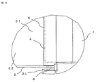
- FIG. 8 is a cross-sectional plan view corresponding to the cross-sectional plan view taken along the line II in FIG. 1
- FIG. 9 is a vertical cross-sectional side view corresponding to the vertical cross-sectional view taken along the line II-II in FIG. It is a cross-sectional plan view equivalent to the cross-sectional plan view in FIG.
- the description of the second embodiment will be made with respect to parts different from those of the first embodiment described above, and the description of the same parts as those of the first embodiment will be omitted.
- the hinge portion packing 5 is attached to the Z-shaped sealing frame 4 as shown in FIGS. 2 and 5.
- the example illustrated in FIGS. 8 and 10 is used.
- the hinge part packing 5 is attached to the inner wall surface 31 of the door 3.
- the gap 7 between the Z-shaped sealing frame 4 and the door 3 is closed by the hinge packing 5 of the door 3 as shown in FIGS. It is structured to protect the device main body 11 inside the box 1 from foreign substances that may enter through the gap 7 between the door 3 and the same effect as in the first embodiment described above. it can. *
- FIG. 11 is a cross-sectional plan view corresponding to the cross-sectional plan view taken along line II in FIG. 1
- FIG. 12 is a cross-sectional plan view corresponding to the cross-sectional plan view taken along line III-III in FIG.
- the description of the third embodiment will be made with respect to parts different from the first embodiment described above, and the description of the same parts as the first embodiment will be omitted.
- the hinge packing 5 is attached to the Z-shaped sealing frame 4, but in the third embodiment, as shown in FIGS. 11 and 12, the main frame 2 is a vertical frame.
- the W-shaped sealing frame 4 is attached to the W-shaped sealing frame 4, and the piece (one piece) 61 on the box 1 side of the hinge 6 and the hinge packing 5 are attached.
- the gap 7 between the W-shaped sealing frame 4 and the door 3 is closed by the hinge packing 5 as shown in FIG.
- the device main body 11 inside the box 1 is protected from foreign matter that may enter through the gap 7 therebetween, and the same effects as those of the first embodiment can be obtained.
- the electric device according to the third embodiment has an inner wall surface 31 of the door 3 in a state in which the distal end portion 42 of the sealing frame 4 is formed in an L shape and the device main body outlet 12 is closed.
- the hinge portion packing 5 is interposed between the inner wall surface 31 of the door 3 in a state where the device main body outlet 12 is closed and the most distal portion 421.
- the hinge portion packing 5 is attached to a surface of the most distal portion 421 parallel to the inner wall surface 31 that faces the inner wall surface 31 of the closed door 3.
Abstract
An electric device is provided with: a sealing frame 4 having an inner end portion 41 attached to a main frame 2 of the external wall of a box body 1, having an end portion 42 facing the internal wall surface 31 of a door 3 in a state of closing an opening 12 for taking out a device body, and extending at least over the length of the rotating shaft 63 of a hinge 6 in the shaft direction; and a hinge portion packing 5 interposed between the surface of the end portion 42 of the sealing frame 4, which faces the door 3, and the internal wall surface 31 of the door 3 and preventing a foreign object outside the box body 1 from intruding at the hinge 6 portion from between the box body 1 and the door 3 into the inside of the box body 1. With an inexpensive and simple structure, the electric device can effectively prevent a foreign object outside the box body 1 from intruding from between the box body 1 and the door 3 into the inside of the box body 1.
Description
この発明は、機器本体を機器本体取り出し口から取り出し可能に収納する箱体、および前記箱体にヒンジにより開閉自在に枢着され前記機器本体取り出し口を開閉する扉を備えた電気機器に関するものである。
The present invention relates to a box body that houses a device main body so as to be removable from a device main body outlet, and an electric device that includes a door that is pivotally attached to the box body by a hinge so as to be opened and closed, and opens and closes the device main body outlet. is there.
箱体側および扉の内側にヒンジを設け、扉を回転させて開閉させるコントロールセンタ、配電盤等の電気機器では、扉の開き角度を確保するために、ヒンジ周辺の箱体と扉の間に隙間を設ける必要がある。
上記構造の電気機器では、扉のヒンジ周辺に設けた隙間から外来固形物の電気機器内への侵入を防ぐため,特許文献1の配電盤のように、箱体側ヒンジを扉高さまで伸ばすことで、扉と箱体との間の隙間を塞ぐ構造や、特許文献2の閉鎖配電盤のように箱体側フレームもしくは延長部材に防塵パッキンを貼付けし、扉側に台座を設けて、防塵パッキンと台座が接することで扉と箱体との間の隙間を塞ぐ構造としている。 For electrical equipment such as control centers and switchboards that have hinges on the box side and the inside of the door, which are opened and closed by rotating the door, there is a gap between the box around the hinge and the door to ensure the door opening angle. It is necessary to provide.
In the electrical equipment having the above structure, in order to prevent foreign solids from entering the electrical equipment from the gap provided around the hinge of the door, the box-side hinge is extended to the door height as in the switchboard ofPatent Document 1. A structure that closes the gap between the door and the box, or a dust-proof packing is attached to the box-side frame or extension member like the closed switchboard of Patent Document 2, and a pedestal is provided on the door side, and the dust-proof packing and the pedestal Is in a structure that closes the gap between the door and the box.
上記構造の電気機器では、扉のヒンジ周辺に設けた隙間から外来固形物の電気機器内への侵入を防ぐため,特許文献1の配電盤のように、箱体側ヒンジを扉高さまで伸ばすことで、扉と箱体との間の隙間を塞ぐ構造や、特許文献2の閉鎖配電盤のように箱体側フレームもしくは延長部材に防塵パッキンを貼付けし、扉側に台座を設けて、防塵パッキンと台座が接することで扉と箱体との間の隙間を塞ぐ構造としている。 For electrical equipment such as control centers and switchboards that have hinges on the box side and the inside of the door, which are opened and closed by rotating the door, there is a gap between the box around the hinge and the door to ensure the door opening angle. It is necessary to provide.
In the electrical equipment having the above structure, in order to prevent foreign solids from entering the electrical equipment from the gap provided around the hinge of the door, the box-side hinge is extended to the door height as in the switchboard of
特許文献1では、箱体側ヒンジを扉高さまで伸ばして、箱体側ヒンジにより扉と箱体の隙間を塞ぐことで、外来固形物の配電盤内への侵入を防止しているが、扉開閉の際に扉と箱体側ヒンジが干渉しないように箱体側ヒンジと扉の間に隙間を確保する必要があるため、細かい異物や水などの異物の侵入を防ぐことは困難であった。また、箱体側ヒンジは製作し難い形状で高価であるが、コントロールセンタのユニットのように扉の高さが固定でない製品では、変更などで扉の高さが変わった場合、箱体側ヒンジを製作し直す必要があり、コストが高くなっていた。
In Patent Literature 1, the box-side hinge is extended to the height of the door, and the gap between the door and the box is closed by the box-side hinge to prevent foreign solids from entering the switchboard. At this time, it is necessary to secure a gap between the box-side hinge and the door so that the door and the box-side hinge do not interfere with each other. In addition, the box-side hinge is difficult to manufacture and expensive, but for products that do not have a fixed door height, such as a control center unit, if the door height changes due to changes, etc., the box-side hinge Had to be remanufactured and the cost was high.
特許文献2の第1図の構造では、箱体側フレームもしくは延長部材に貼り付けた防塵パッキンと扉側に設けた台座が接し、扉と箱体の隙間を塞ぐことで、外来固形物の配電盤内への侵入を防止しているが、箱体側フレームおよび延長部材と扉側の台座が必要で部品点数増となりコストが高くなっていた。
In the structure of FIG. 1 of Patent Document 2, the dustproof packing affixed to the box side frame or extension member and the pedestal provided on the door side are in contact with each other, and the gap between the door and the box is closed, thereby providing a distribution board for foreign solids. Although intrusion to the inside is prevented, the box side frame, the extension member, and the base on the door side are necessary, which increases the number of parts and increases the cost.
この発明は、前述のような実情に鑑みてなされたもので、機器本体を機器本体取り出し口から取り出し可能に収納する箱体、および前記箱体にヒンジにより開閉自在に枢着され前記機器本体取り出し口を開閉する扉を備えた電気機器にけるヒンジの部分において、箱体と扉との間から、箱体の外部の異物が、箱体の内部に侵入するのを、廉価な簡単な構造で、効果的に防止することを目的とするものである。
The present invention has been made in view of the above-described circumstances, and a box body that accommodates an apparatus main body so as to be removable from an apparatus main body outlet, and is pivotally attached to the box body by a hinge so as to be openable and closable. In the hinge part of electrical equipment with a door that opens and closes the mouth, foreign materials outside the box enter the inside of the box from between the box and the door with an inexpensive and simple structure. The purpose is to prevent effectively.
この発明に係る電気機器は、機器本体を機器本体取り出し口から取り出し可能に収納する箱体、および前記箱体にヒンジにより開閉自在に枢着され前記機器本体取り出し口を開閉する扉を備えた電気機器であって、
前記箱体の外壁の主フレームに内端部が取り付けられると共に先端部が前記機器本体取り出し口を閉じた状態の前記扉の内壁面に対向し少なくとも前記ヒンジのヒンジ回転軸の軸方向の長さに亘って延在する密封用フレーム、および
前記密封用フレームの前記先端部の前記扉との対向面と前記扉の前記内壁面との間に介在し、前記ヒンジの部分において、前記箱体と前記扉との間から、前記箱体の外部の異物が、前記箱体の内部に侵入するのを防止するヒンジ部パッキンを備えている
ものである。
ものである。 An electrical device according to the present invention includes a box that houses a device main body so that the device main body can be removed from the device main body outlet, and an electric door that is pivotally attached to the box body by a hinge so as to be opened and closed. The door opens and closes the device main body outlet. Equipment,
An inner end portion is attached to the main frame of the outer wall of the box body, and a tip end portion faces the inner wall surface of the door in a state where the device main body outlet is closed, and at least the axial length of the hinge rotation axis of the hinge A sealing frame extending over the door, and a front face of the sealing frame that is interposed between a surface facing the door and the inner wall surface of the door, and at the hinge portion, A hinge portion packing is provided to prevent foreign matter outside the box from entering the inside of the box from between the door.
Is.
この発明は、機器本体を機器本体取り出し口から取り出し可能に収納する箱体、および前記箱体にヒンジにより開閉自在に枢着され前記機器本体取り出し口を開閉する扉を備えた電気機器であって、前記箱体の外壁の主フレームに内端部が取り付けられると共に先端部が前記機器本体取り出し口を閉じた状態の前記扉の内壁面に対向し少なくとも前記ヒンジのヒンジ回転軸の軸方向の長さに亘って延在する密封用フレーム、および前記密封用フレームの前記先端部の前記扉との対向面と前記扉の前記内壁面との間に介在し、前記ヒンジの部分において、前記箱体と前記扉との間から、前記箱体の外部の異物が、前記箱体の内部に侵入するのを防止するヒンジ部パッキンを備えているので、前記ヒンジの部分において、前記箱体と前記扉との間から、前記箱体の外部の異物が、前記箱体の内部に侵入するのを、廉価な簡単な構造で、効果的に防止することができる。
The present invention is an electric device including a box body that houses a device main body so as to be removable from a device main body outlet, and a door that is pivotally attached to the box body by a hinge so as to be opened and closed and opens and closes the device main body outlet. The inner end portion is attached to the main frame of the outer wall of the box body, and the front end portion faces the inner wall surface of the door in a state where the device main body outlet is closed, and at least the axial length of the hinge rotation shaft of the hinge A sealing frame extending across the wall, and the front end of the sealing frame interposed between a surface facing the door and the inner wall surface of the door, and at the hinge portion, the box body And the door are provided with a hinge packing that prevents foreign matter outside the box from entering the inside of the box, so that the box and the door at the hinge portion. With From the outside of the foreign matter of the box body, from entering the interior of the box body, an inexpensive simple structure, it can be effectively prevented.
実施の形態1.
以下、この発明の実施の形態1を図1、図2、図3、図4、図5、図6及び図7に基づいて説明する。図1は電気機器の扉を閉めた状態を示す斜視図、図2は図1のI-I線における横断平面図、図3は図1のII-II線における縦断側面図、図4は電気機器の扉を開いた状態を示す斜視図、図5は図4のIII-III線における横断平面図、図6は図4のIV-IV線における縦断側面図、図7は密封用フレームおよびヒンジ部パッキンの全体の外形を示す斜視図である。Embodiment 1 FIG.
Embodiment 1 of the present invention will be described below with reference to FIGS. 1, 2, 3, 4, 4, 5, 6, and 7. FIG. 1 is a perspective view showing a state in which the door of the electric device is closed, FIG. 2 is a cross-sectional plan view taken along line II in FIG. 1, FIG. 3 is a longitudinal side view taken along line II-II in FIG. FIG. 5 is a cross-sectional plan view taken along line III-III in FIG. 4, FIG. 6 is a longitudinal side view taken along line IV-IV in FIG. 4, and FIG. 7 is a sealing frame and hinge part packing. It is a perspective view which shows the external shape of the whole.
以下、この発明の実施の形態1を図1、図2、図3、図4、図5、図6及び図7に基づいて説明する。図1は電気機器の扉を閉めた状態を示す斜視図、図2は図1のI-I線における横断平面図、図3は図1のII-II線における縦断側面図、図4は電気機器の扉を開いた状態を示す斜視図、図5は図4のIII-III線における横断平面図、図6は図4のIV-IV線における縦断側面図、図7は密封用フレームおよびヒンジ部パッキンの全体の外形を示す斜視図である。
本実施の形態1における電気機器は、図1から図7に例示のように、電気機器の箱体1、機器本体11、保守点検時など必要に応じて箱体1から機器本体11を取り出すための機器本体取り出し口12、箱体1の主フレーム2、箱体1に開閉自在に枢着された扉3、扉の内壁面31、扉の自由端32、上側の扉(上段の機器の扉)3U、下側の扉(下段の機器の扉)3L、主フレーム2に固着された密封用フレーム4、密封用フレーム4の内端部41、密封用フレーム4の先端部42、密封用フレーム4の中間部43、ヒンジ部パッキン5、扉3の上部および下部の2箇所に配設された複数個のヒンジ6、各ヒンジ6の一方の片(箱体1の側に固定された片)61、各ヒンジ6の他方の片(扉3の側に固定された片)62、各ヒンジ6のヒンジ回転軸63(一方の片61と他方の片62とを枢着してヒンジ6を構成する軸)、箱体1と扉3との間の隙間7、および周縁部パッキン8、を有している例である。
As shown in FIGS. 1 to 7, the electrical device according to the first embodiment is used to take out the device body 11 from the box 1 as necessary, such as the box 1 of the electrical device, the device body 11, and maintenance. Device main body outlet 12, main frame 2 of box 1, door 3 pivotally attached to box 1, inner wall surface 31 of door, free end 32 of door, upper door (door of upper device) 3U, lower door (lower equipment door) 3L, sealing frame 4 fixed to the main frame 2, inner end 41 of the sealing frame 4, tip 42 of the sealing frame 4, sealing frame 4, intermediate portion 43, hinge packing 5, a plurality of hinges 6 disposed at two locations above and below door 3, one piece of each hinge 6 (piece fixed to the box 1 side) 61, the other piece of each hinge 6 (the piece fixed to the door 3 side) 62, the hinge of each hinge 6 The rotary shaft 63 (the shaft constituting the hinge 6 by pivoting the one piece 61 and the other piece 62), the gap 7 between the box 1 and the door 3, and the peripheral packing 8 This is an example.
本実施の形態の電気機器は、箱体1の縦フレームである主フレーム2にZ字形状の密封用フレーム4を取付け、密封用フレーム4にヒンジ6の一方の片(箱体側の片)61とヒンジ部パッキン5とを取付け、ヒンジ7の他方の片(扉側の片)62を扉3に取り付け、ヒンジ6の一方の片61とヒンジ6の他方の片62とに、これら両片61,62に跨ってヒンジ回転軸63を差し込むことによって、扉3を箱体1に開閉自在に取り付ける構造である。
In the electrical apparatus according to the present embodiment, a Z-shaped sealing frame 4 is attached to a main frame 2 that is a vertical frame of the box 1, and one piece of a hinge 6 (a piece on the box side) is attached to the sealing frame 4. 61 and the hinge part packing 5 are attached, the other piece 62 (the door side piece) 62 of the hinge 7 is attached to the door 3, and one piece 61 of the hinge 6 and the other piece 62 of the hinge 6 are both of these pieces. The door 3 is attached to the box 1 so as to be freely opened and closed by inserting a hinge rotation shaft 63 across 61 and 62.
ここで、箱体1と扉3との間の隙間7について説明する。電気機器の箱体1には、内部には、例えば配電盤としての機能上必要な機器及び構成部材などの機器本体11が収納されており、例えば、箱体1内の機器本体11のメンテナンスで機器本体11を箱体1から引出したり、構成部材の状態を確認したりする時には、必ず扉3を開閉させる。その場合、扉3はヒンジ回転軸63を中心とした回転運動となるため, 箱体1の側および扉3の内側にヒンジ6を設けた電気機器においては、箱体1と扉3との間に隙間7を設ける必要がある。
Here, the gap 7 between the box 1 and the door 3 will be described. Inside the box 1 of the electrical equipment, for example, equipment main bodies 11 such as equipment and components necessary for function as a switchboard are accommodated. For example, the equipment is maintained by maintenance of the equipment main body 11 inside the box 1. When the main body 11 is pulled out from the box 1 or the state of the constituent members is confirmed, the door 3 is always opened and closed. In that case, since the door 3 is rotated around the hinge rotation shaft 63, in the electrical equipment provided with the hinge 6 on the side of the box 1 and the inside of the door 3, the door 3 is placed between the box 1 and the door 3. It is necessary to provide a gap 7 on the surface.
一方、配電盤などの電気機器は様々な場所に設置されることから、例えば、電気機器の操作者が誤って内部充電部に触れないように、また,虫や小動物などが電気機器内に侵入して充電部で短絡事故を起こすことがないように、 また、水が配電盤内に侵入して機器等が故障しないように、外部から電気機器の内部へと侵入する物体や水などの異物から、電気機器の箱体1の内部の機器本体11を保護することが必要とされる。
On the other hand, since electrical devices such as switchboards are installed in various places, for example, an operator of the electrical device should not touch the internal charging part accidentally, and insects and small animals can enter the electrical device. In order to prevent short circuit accidents in live parts, and to prevent water from penetrating the switchboard and causing equipment breakdown, etc. It is necessary to protect the equipment body 11 inside the box 1 of the electrical equipment.
本実施の形態1おける電気機器では、3扉の開閉が可能な構造かつ、細かい異物や水などの所謂異物から保護するための構造として、箱体1の側のZ字形状の密封用フレーム4を、扉3の高さ方向全体にわたる遮蔽板構造として箱体1の主フレーム2に取付け、Z字形状の密封用フレーム4に扉3の高さ方向全体にわたるヒンジ部パッキン5を取付け、扉3を閉めた際、箱体1と扉3との間の隙間7を塞ぎ、ヒンジ部以外については、扉3と周縁部パッキン(ヒンジ部以外)8とが接すること構造としてあることを特徴としている。
In the electrical device according to the first embodiment, a Z-shaped sealing frame 4 on the side of the box 1 is used as a structure capable of opening and closing three doors and a structure for protecting from so-called foreign matters such as fine foreign matter and water. Is attached to the main frame 2 of the box 1 as a shielding plate structure over the entire height direction of the door 3, and a hinge packing 5 is attached to the Z-shaped sealing frame 4 over the entire height direction of the door 3. When the door is closed, the gap 7 between the box 1 and the door 3 is closed, and the door 3 and the peripheral portion packing (other than the hinge portion) 8 are in contact with each other except for the hinge portion. .
箱体1の側のヒンジ6の部分は、箱体1の側のZ字形状の密封用フレーム4と箱体1の側のヒンジ6の片61のみで構成しているため、特許文献2の第1図のような箱体側フレームもしくは延長部材の防塵パッキンと扉側の台座とが接する構造に比べて、部品点数の削減が可能となる。また、箱体1の側の小形のヒンジ6と、箱体1の側の単純な形状のZ字形状の密封用フレーム4の安価な部品の採用により、特許文献1のような箱体1の側のヒンジを扉3の高さまで伸ばして遮蔽する構造に比べて、コスト削減の効果がある。
さらに、箱体1の側のヒンジ6の片61と箱体1の側のZ字形状の密封用フレーム4とを別部品にすることで、扉の高さが変わった場合も、Z字形状の密封用フレーム4のみを取り替えて、箱体1の側のヒンジ6の片61は同じものを流用することができる。 The portion of thehinge 6 on the side of the box 1 is composed of only the Z-shaped sealing frame 4 on the side of the box 1 and the piece 61 of the hinge 6 on the side of the box 1. The number of parts can be reduced as compared with the structure in which the dust frame packing of the box body side or the extension member and the base on the door side are in contact with each other as shown in FIG. Further, by adopting inexpensive parts such as a small hinge 6 on the side of the box 1 and a simple Z-shaped sealing frame 4 on the side of the box 1, the box 1 as in Patent Document 1 can be used. Compared with a structure in which the hinge on the side is extended to the height of the door 3 and shielded, there is an effect of cost reduction.
Furthermore, even if the height of the door changes by making thepiece 61 of the hinge 6 on the side of the box 1 and the Z-shaped sealing frame 4 on the side of the box 1 different parts, the Z-shape By replacing only the sealing frame 4, the same piece 61 of the hinge 6 on the side of the box 1 can be used.
さらに、箱体1の側のヒンジ6の片61と箱体1の側のZ字形状の密封用フレーム4とを別部品にすることで、扉の高さが変わった場合も、Z字形状の密封用フレーム4のみを取り替えて、箱体1の側のヒンジ6の片61は同じものを流用することができる。 The portion of the
Furthermore, even if the height of the door changes by making the
従って、本実施の形態1によれば、ヒンジ6部における箱体1と扉3との間の隙間7からの異物の箱体1内への侵入を防止して箱体1内の機器本体11を異物から保護しつつも、安価な電気機器を構成できる。
Therefore, according to the first embodiment, foreign matter can be prevented from entering the box 1 through the gap 7 between the box 1 and the door 3 at the hinge 6, and the device main body 11 in the box 1 can be prevented. It is possible to construct an inexpensive electric device while protecting the device from foreign matter.
なお、本実施の形態1の電気機器は、別な観点から、機器本体11を機器本体取り出し口12から取り出し可能に収納する箱体1、および箱体1にヒンジ6により開閉自在に枢着され機器本体取り出し口12を開閉する扉3を備えた電気機器であって、箱体1の外壁の主フレーム2に内端部41が取り付けられると共に先端部42が機器本体取り出し口12を閉じた状態の扉3の内壁面31に対向し少なくともヒンジ6のヒンジ回転軸63の軸方向の長さに亘って延在する密封用フレーム4、および密封用フレーム4の先端部42の扉3との対向面と扉3の内壁面31との間に介在し、ヒンジ6の部分において、箱体1と扉3との間から、箱体1の外部の異物が、箱体1の内部に侵入するのを防止するヒンジ部パッキン5を備えている電気機器である。
From another point of view, the electrical device according to the first embodiment is pivotally attached to the box body 1 that houses the device body 11 so that the device body 11 can be removed from the device body outlet 12 and can be opened and closed by a hinge 6. An electric device having a door 3 for opening and closing the device main body outlet 12, wherein the inner end 41 is attached to the main frame 2 of the outer wall of the box 1 and the tip 42 closes the device main body outlet 12. The sealing frame 4 facing the inner wall surface 31 of the door 3 and extending at least the axial length of the hinge rotation shaft 63 of the hinge 6, and the front end portion 42 of the sealing frame 4 facing the door 3. The foreign matter outside the box 1 enters the inside of the box 1 from between the box 1 and the door 3 at the hinge 6 portion between the surface and the inner wall 31 of the door 3. Electricity provided with hinge part packing 5 for preventing It is a vessel.
また、かかる構造の電気機器において、ヒンジ部パッキン5が、密封用フレーム4の先端部42に取り付けられ、密封用フレーム4が、内端部41と先端部42との間に、機器本体取り出し口12を閉じた状態の扉3の内壁面31と平行な中間部43を有し、内端部41と先端部42と中間部43とにより密封用フレーム4がZ字形状に形成されており、内端部41と先端部42と中間部43とが一枚の板材で形成されており、ヒンジ6の一方の片61が密封用フレーム4の中間部43に取り付けられヒンジ6の他方の片62が扉3の内壁面31に取り付けられており、扉3の箱体1の側の周縁部と箱体1との間に箱体1と扉3との間から箱体1の外部の異物が箱体の内部に侵入するのを防止する周縁部パッキン8が設けられており、周縁部パッキン8が箱体1に取り付けられており、ヒンジ部パッキン5と周縁部パッキン8とにより箱体1の外部から異物が箱体1の内部に侵入するのを防止する構造であり、ヒンジ部パッキン5がヒンジ6より扉3の自由端32の側に位置している事例である。
なお、周縁部パッキン8は、扉3の側に取り付けてもよい。 Further, in the electrical apparatus having such a structure, thehinge part packing 5 is attached to the front end part 42 of the sealing frame 4, and the sealing frame 4 is provided between the inner end part 41 and the front end part 42. 12 has an intermediate portion 43 parallel to the inner wall surface 31 of the door 3 in a closed state, and the sealing frame 4 is formed in a Z shape by the inner end portion 41, the tip end portion 42 and the intermediate portion 43. The inner end portion 41, the tip end portion 42, and the intermediate portion 43 are formed of a single plate material, and one piece 61 of the hinge 6 is attached to the intermediate portion 43 of the sealing frame 4 and the other piece 62 of the hinge 6. Is attached to the inner wall surface 31 of the door 3, and foreign matter outside the box 1 is between the box 1 and the peripheral edge of the door 3 on the box 1 side and between the box 1. A peripheral edge packing 8 is provided to prevent entry into the inside of the box, and the peripheral edge part. The packing 8 is attached to the box 1, and the hinge part packing 5 and the peripheral part packing 8 prevent foreign matter from entering the box 1 from the outside of the box 1, and the hinge part packing. In this example, 5 is located on the free end 32 side of the door 3 from the hinge 6.
The peripheral edge packing 8 may be attached to thedoor 3 side.
なお、周縁部パッキン8は、扉3の側に取り付けてもよい。 Further, in the electrical apparatus having such a structure, the
The peripheral edge packing 8 may be attached to the
実施の形態2.
以下、この発明の実施の形態2を図8,図9,図10に基づいて説明する。図8は図1のI-I線における横断平面図に相当する横断平面図、図9は図1のII-II線における縦断側面図に相当する縦断側面図、図10は図4のIII-III線における横断平面図に相当する横断平面図である。本実施の形態2の説明は、前述の実施の形態1と異なる部分について行い、実施の形態1と同様な部分については説明を割愛する。Embodiment 2. FIG.
The second embodiment of the present invention will be described below with reference to FIGS. 8, 9, and 10. FIG. 8 is a cross-sectional plan view corresponding to the cross-sectional plan view taken along the line II in FIG. 1, FIG. 9 is a vertical cross-sectional side view corresponding to the vertical cross-sectional view taken along the line II-II in FIG. It is a cross-sectional plan view equivalent to the cross-sectional plan view in FIG. The description of the second embodiment will be made with respect to parts different from those of the first embodiment described above, and the description of the same parts as those of the first embodiment will be omitted.
以下、この発明の実施の形態2を図8,図9,図10に基づいて説明する。図8は図1のI-I線における横断平面図に相当する横断平面図、図9は図1のII-II線における縦断側面図に相当する縦断側面図、図10は図4のIII-III線における横断平面図に相当する横断平面図である。本実施の形態2の説明は、前述の実施の形態1と異なる部分について行い、実施の形態1と同様な部分については説明を割愛する。
The second embodiment of the present invention will be described below with reference to FIGS. 8, 9, and 10. FIG. 8 is a cross-sectional plan view corresponding to the cross-sectional plan view taken along the line II in FIG. 1, FIG. 9 is a vertical cross-sectional side view corresponding to the vertical cross-sectional view taken along the line II-II in FIG. It is a cross-sectional plan view equivalent to the cross-sectional plan view in FIG. The description of the second embodiment will be made with respect to parts different from those of the first embodiment described above, and the description of the same parts as those of the first embodiment will be omitted.
前述の実施の形態1では、図2および図5のようにZ字形状の密封用フレーム4にヒンジ部パッキン5を取付けているが、本実施の形態2では、図8および図10に例示のように、扉3に、ヒンジ部パッキン5を取付けた事例を示してある。ヒンジ部パッキン5は、扉3の内壁面31に取り付けられている。
In the first embodiment described above, the hinge portion packing 5 is attached to the Z-shaped sealing frame 4 as shown in FIGS. 2 and 5. In the second embodiment, the example illustrated in FIGS. 8 and 10 is used. Thus, the example which attached the hinge part packing 5 to the door 3 is shown. The hinge part packing 5 is attached to the inner wall surface 31 of the door 3.
扉3を閉めた際、図8,図9のように、Z字形状の密封用フレーム4と扉3との隙間7が、扉3のヒンジ部パッキン5により塞がれることで、箱体1と扉3の間の隙間7から侵入する可能性のある異物から、箱体1の内部の機器本体11を保護する構造となっており、前述の実施の形態1と同等の効果を奏することができる。
When the door 3 is closed, the gap 7 between the Z-shaped sealing frame 4 and the door 3 is closed by the hinge packing 5 of the door 3 as shown in FIGS. It is structured to protect the device main body 11 inside the box 1 from foreign substances that may enter through the gap 7 between the door 3 and the same effect as in the first embodiment described above. it can. *
実施の形態3.
以下、本実施の形態を図11,図12に基づいて説明する。図11は図1のI-I線における横断平面図に相当する横断平面図、図12は図4のIII-III線における横断平面図に相当する横断平面図である。本実施の形態3の説明は、前述の実施の形態1と異なる部分について行い、実施の形態1と同様な部分については説明を割愛する。Embodiment 3 FIG.
Hereinafter, the present embodiment will be described with reference to FIGS. 11 is a cross-sectional plan view corresponding to the cross-sectional plan view taken along line II in FIG. 1, and FIG. 12 is a cross-sectional plan view corresponding to the cross-sectional plan view taken along line III-III in FIG. The description of the third embodiment will be made with respect to parts different from the first embodiment described above, and the description of the same parts as the first embodiment will be omitted.
以下、本実施の形態を図11,図12に基づいて説明する。図11は図1のI-I線における横断平面図に相当する横断平面図、図12は図4のIII-III線における横断平面図に相当する横断平面図である。本実施の形態3の説明は、前述の実施の形態1と異なる部分について行い、実施の形態1と同様な部分については説明を割愛する。
Hereinafter, the present embodiment will be described with reference to FIGS. 11 is a cross-sectional plan view corresponding to the cross-sectional plan view taken along line II in FIG. 1, and FIG. 12 is a cross-sectional plan view corresponding to the cross-sectional plan view taken along line III-III in FIG. The description of the third embodiment will be made with respect to parts different from the first embodiment described above, and the description of the same parts as the first embodiment will be omitted.
前述の実施の形態1では、Z字形状の密封用フレーム4にヒンジ部パッキン5を取付けているが、本実施の形態3では、図11、図12のように、縦フレームである主フレーム2に、W字形状の密封用フレーム4を取付け、W字形状の密封用フレーム4に、ヒンジ6の箱体1の側の片(一方の片)61と、ヒンジ部パッキン5を取付けてある。
In the first embodiment described above, the hinge packing 5 is attached to the Z-shaped sealing frame 4, but in the third embodiment, as shown in FIGS. 11 and 12, the main frame 2 is a vertical frame. The W-shaped sealing frame 4 is attached to the W-shaped sealing frame 4, and the piece (one piece) 61 on the box 1 side of the hinge 6 and the hinge packing 5 are attached.
扉3を閉めた際、図11のようにW字形状の密封用フレーム4と扉3との間の隙間7が、ヒンジ部パッキン5により塞がれることで、箱体1と扉3との間の隙間7から侵入する可能性のある異物から、箱体1の内部の機器本体11を保護する構造となっており、前述の実施の形態1と同等の効果を奏することができる。
When the door 3 is closed, the gap 7 between the W-shaped sealing frame 4 and the door 3 is closed by the hinge packing 5 as shown in FIG. The device main body 11 inside the box 1 is protected from foreign matter that may enter through the gap 7 therebetween, and the same effects as those of the first embodiment can be obtained.
なお、本実施の形態3の電気機器は、別な観点から、密封用フレーム4の先端部42が、L字状に形成され、機器本体取り出し口12を閉じた状態の扉3の内壁面31と平行な最先端部421を有し、機器本体取り出し口12を閉じた状態の扉3の内壁面31と最先端部421との間に、ヒンジ部パッキン5が介在している.ヒンジ部パッキン5は、内壁面31と平行な最先端部421の、閉じた状態の扉3の内壁面31に対向する面に取り付けられている。
Note that, from another point of view, the electric device according to the third embodiment has an inner wall surface 31 of the door 3 in a state in which the distal end portion 42 of the sealing frame 4 is formed in an L shape and the device main body outlet 12 is closed. The hinge portion packing 5 is interposed between the inner wall surface 31 of the door 3 in a state where the device main body outlet 12 is closed and the most distal portion 421. The hinge portion packing 5 is attached to a surface of the most distal portion 421 parallel to the inner wall surface 31 that faces the inner wall surface 31 of the closed door 3.
なお、各図中、同一符合は同一または相当部分を示す。
なお、本発明は、その発明の範囲内において、各実施の形態を適宜、変形、省略、組み合わせることができる。 In addition, in each figure, the same code | symbol shows the same or an equivalent part.
In the present invention, each embodiment can be appropriately modified, omitted, or combined within the scope of the invention.
なお、本発明は、その発明の範囲内において、各実施の形態を適宜、変形、省略、組み合わせることができる。 In addition, in each figure, the same code | symbol shows the same or an equivalent part.
In the present invention, each embodiment can be appropriately modified, omitted, or combined within the scope of the invention.
1 電気機器の箱体、11 機器本体、
12 機器本体取り出し口、2 箱体の主フレーム、
3 扉、31 扉の内壁面、32 扉の自由端、
3U 上側の扉、3L 下側の扉、4 密封用フレーム、
41 密封用フレームの内端部、42 密封用フレームの先端部、
421 密封用フレームの先端部の最先端部、
43 密封用フレームの中間部、5 ヒンジ部パッキン、
6 ヒンジ、61 ヒンジの一方の片、62 ヒンジの他方の片、
63 ヒンジ回転軸、7 箱体と扉との間の隙間、
8 周縁部パッキン。 1 box of electrical equipment, 11 equipment body,
12 Main body outlet, 2 box main frame,
3 door, 31 inner wall surface of door, 32 free end of door,
3U upper door, 3L lower door, 4 sealing frame,
41 inner end of the sealing frame, 42 tip of the sealing frame,
421 The most advanced part of the tip of the sealing frame,
43 Middle part of sealing frame, 5 Packing of hinge part,
6 hinges, 61 one piece of hinge, 62 the other piece of hinge,
63 Hinge rotation shaft, 7 Clearance between box and door,
8 Peripheral packing.
Claims (12)
- 機器本体を機器本体取り出し口から取り出し可能に収納する箱体、および前記箱体にヒンジにより開閉自在に枢着され前記機器本体取り出し口を開閉する扉を備えた電気機器であって、
前記箱体の外壁の主フレームに内端部が取り付けられると共に先端部が前記機器本体取り出し口を閉じた状態の前記扉の内壁面に対向し少なくとも前記ヒンジのヒンジ回転軸の軸方向の長さに亘って延在する密封用フレーム、および
前記密封用フレームの前記先端部の前記扉との対向面と前記扉の前記内壁面との間に介在し、前記ヒンジの部分において、前記箱体と前記扉との間から、前記箱体の外部の異物が、前記箱体の内部に侵入するのを防止するヒンジ部パッキンを備えている
ことを特徴とする電気機器。 A box that houses the device main body so that it can be removed from the device main body outlet, and an electric device that includes a door that is pivotally attached to the box by a hinge so as to be opened and closed, and opens and closes the device main body outlet,
An inner end portion is attached to the main frame of the outer wall of the box body, and a tip end portion faces the inner wall surface of the door in a state where the device main body outlet is closed, and at least the axial length of the hinge rotation axis of the hinge A sealing frame extending over the door, and a front face of the sealing frame that is interposed between a surface facing the door and the inner wall surface of the door, and at the hinge portion, An electric device comprising a hinge packing that prevents foreign matter outside the box from entering the inside of the box from between the door. - 請求項1に記載の電気機器において、
前記ヒンジ部パッキンが、前記密封用フレームの前記先端部に取り付けられている
ことを特徴とする電気機器。 The electric device according to claim 1,
The electrical device, wherein the hinge packing is attached to the tip of the sealing frame. - 請求項1に記載の電気機器において、
前記ヒンジ部パッキンが前記扉の前記内壁面に取り付けられている
ことを特徴とする電気機器。 The electric device according to claim 1,
The electrical device, wherein the hinge packing is attached to the inner wall surface of the door. - 請求項1から請求項3のいずれか一項に記載の電気機器において、
前記密封用フレームが、前記内端部と前記先端部との間に、前記機器本体取り出し口を閉じた状態の前記扉の前記内壁面と平行な中間部を有し、
前記内端部と前記先端部と前記中間部とにより前記密封用フレームがZ字形状に形成されている
ことを特徴とする電気機器。 In the electric equipment according to any one of claims 1 to 3,
The sealing frame has an intermediate portion parallel to the inner wall surface of the door in a state where the device main body outlet is closed, between the inner end portion and the tip end portion.
The electrical device, wherein the sealing frame is formed in a Z shape by the inner end portion, the distal end portion, and the intermediate portion. - 請求項4に記載の電気機器において、
前記先端部がL字状に形成され、前記機器本体取り出し口を閉じた状態の前記扉の前記内壁面と平行な最先端部を有し、
前記機器本体取り出し口を閉じた状態の前記扉の前記内壁面と前記最先端部との間に、前記ヒンジ部パッキンが介在している
ことを特徴とする電気機器。 The electric device according to claim 4,
The distal end portion is formed in an L shape, and has a most advanced portion parallel to the inner wall surface of the door in a state where the device main body outlet is closed,
The electrical device, wherein the hinge portion packing is interposed between the inner wall surface of the door and the most advanced portion in a state where the device main body outlet is closed. - 請求項4または請求項5に記載の電気機器において、
前記内端部と前記先端部と前記中間部とが、一枚の板材で形成されている
ことを特徴とする電気機器。 In the electric device according to claim 4 or 5,
The electric device, wherein the inner end portion, the tip end portion, and the intermediate portion are formed of a single plate material. - 請求項4または請求項5に記載の電気機器において、
前記ヒンジの一方の片が、前記密封用フレームの前記中間部に取り付けられ、
前記ヒンジの他方の片が、前記扉の前記内壁面に取り付けられている
ことを特徴とする電気機器。 In the electric device according to claim 4 or 5,
One piece of the hinge is attached to the intermediate portion of the sealing frame;
The other piece of the hinge is attached to the inner wall surface of the door. - 請求項1から請求項7のいずれか一項に記載の電気機器において、
前記扉の前記箱体の側の周縁部と前記箱体との間に、前記箱体と前記扉との間から、前記箱体の外部の前記異物が、前記箱体の内部に侵入するのを防止する周縁部パッキンが設けられている
ことを特徴とする電気機器。 In the electric equipment according to any one of claims 1 to 7,
The foreign matter outside the box enters the inside of the box from between the box and the door, between the peripheral part of the door on the side of the box and the box. An electric device characterized by being provided with a peripheral portion packing for preventing the above-mentioned problem. - 請求項8に記載の電気機器において、
前記周縁部パッキンが前記箱体に取り付けられている
ことを特徴とする電気機器。 The electric device according to claim 8,
The electric device characterized in that the peripheral edge packing is attached to the box. - 請求項8に記載の電気機器において、
前記周縁部パッキンが前記扉に取り付けられていることを特徴とする電気機器。 The electric device according to claim 8,
The electrical equipment, wherein the peripheral edge packing is attached to the door. - 請求項8から請求項10のいずれか一項に記載の電気機器において、
前記ヒンジ部パッキンと前記周縁部パッキンとにより、前記箱体の外部から、前記異物が、前記箱体の内部に侵入するのを防止する
ことを特徴とする電気機器。 In the electric equipment according to any one of claims 8 to 10,
The electric device, wherein the foreign matter is prevented from entering the inside of the box from the outside of the box by the hinge part packing and the peripheral part packing. - 請求項1から請求項11のいずれか一項に記載の電気機器において、
前記ヒンジ部パッキンが、前記ヒンジより前記扉の自由端の側に位置している
ことを特徴とする電気機器。 In the electric equipment according to any one of claims 1 to 11,
The electric device characterized in that the hinge part packing is located closer to the free end of the door than the hinge.
Priority Applications (3)
| Application Number | Priority Date | Filing Date | Title |
|---|---|---|---|
| EP17905218.8A EP3611813B1 (en) | 2017-04-11 | 2017-04-11 | Electric device |
| JP2019512082A JPWO2018189807A1 (en) | 2017-04-11 | 2017-04-11 | Electrical equipment |
| PCT/JP2017/014817 WO2018189807A1 (en) | 2017-04-11 | 2017-04-11 | Electric device |
Applications Claiming Priority (1)
| Application Number | Priority Date | Filing Date | Title |
|---|---|---|---|
| PCT/JP2017/014817 WO2018189807A1 (en) | 2017-04-11 | 2017-04-11 | Electric device |
Publications (1)
| Publication Number | Publication Date |
|---|---|
| WO2018189807A1 true WO2018189807A1 (en) | 2018-10-18 |
Family
ID=63793217
Family Applications (1)
| Application Number | Title | Priority Date | Filing Date |
|---|---|---|---|
| PCT/JP2017/014817 WO2018189807A1 (en) | 2017-04-11 | 2017-04-11 | Electric device |
Country Status (3)
| Country | Link |
|---|---|
| EP (1) | EP3611813B1 (en) |
| JP (1) | JPWO2018189807A1 (en) |
| WO (1) | WO2018189807A1 (en) |
Cited By (1)
| Publication number | Priority date | Publication date | Assignee | Title |
|---|---|---|---|---|
| CN112770554A (en) * | 2019-10-21 | 2021-05-07 | 三星电子株式会社 | Electronic device including dustproof structure |
Citations (4)
| Publication number | Priority date | Publication date | Assignee | Title |
|---|---|---|---|---|
| JPS53133131U (en) * | 1977-03-29 | 1978-10-21 | ||
| JPH0414404A (en) | 1990-05-07 | 1992-01-20 | Hisaka Works Ltd | Processing apparatus for treating wood under high temperature and high pressure steam |
| JP2006253213A (en) * | 2005-03-08 | 2006-09-21 | Chugoku Electric Power Co Inc:The | Accommodation box |
| JP2014166122A (en) | 2013-02-28 | 2014-09-08 | Mitsubishi Electric Corp | Door structure of distribution board |
Family Cites Families (10)
| Publication number | Priority date | Publication date | Assignee | Title |
|---|---|---|---|---|
| JPS5182928U (en) * | 1974-12-26 | 1976-07-02 | ||
| DE3344598C1 (en) * | 1983-12-09 | 1984-09-13 | Loh Kg Rittal Werk | Frame for a control cabinet |
| GB2151461B (en) * | 1983-12-16 | 1987-08-26 | Loh Kg Rittal Werk | Cabinets |
| JPS62185405U (en) * | 1986-05-12 | 1987-11-25 | ||
| JPH023109U (en) * | 1988-06-17 | 1990-01-10 | ||
| JPH0414404U (en) * | 1990-05-28 | 1992-02-05 | ||
| JP3074998B2 (en) * | 1993-02-22 | 2000-08-07 | 富士電機株式会社 | Door mounting device for outdoor switchboard |
| JP4684254B2 (en) * | 2007-03-05 | 2011-05-18 | 三菱電機株式会社 | Panel casing device |
| JP2015061040A (en) * | 2013-09-20 | 2015-03-30 | 河村電器産業株式会社 | Cabinet |
| JP6187117B2 (en) * | 2013-10-07 | 2017-08-30 | 富士電機株式会社 | Electrical equipment housing |
-
2017
- 2017-04-11 EP EP17905218.8A patent/EP3611813B1/en active Active
- 2017-04-11 WO PCT/JP2017/014817 patent/WO2018189807A1/en unknown
- 2017-04-11 JP JP2019512082A patent/JPWO2018189807A1/en active Pending
Patent Citations (4)
| Publication number | Priority date | Publication date | Assignee | Title |
|---|---|---|---|---|
| JPS53133131U (en) * | 1977-03-29 | 1978-10-21 | ||
| JPH0414404A (en) | 1990-05-07 | 1992-01-20 | Hisaka Works Ltd | Processing apparatus for treating wood under high temperature and high pressure steam |
| JP2006253213A (en) * | 2005-03-08 | 2006-09-21 | Chugoku Electric Power Co Inc:The | Accommodation box |
| JP2014166122A (en) | 2013-02-28 | 2014-09-08 | Mitsubishi Electric Corp | Door structure of distribution board |
Cited By (2)
| Publication number | Priority date | Publication date | Assignee | Title |
|---|---|---|---|---|
| CN112770554A (en) * | 2019-10-21 | 2021-05-07 | 三星电子株式会社 | Electronic device including dustproof structure |
| US11625074B2 (en) | 2019-10-21 | 2023-04-11 | Samsung Electronics Co., Ltd. | Electronic device including dustproof structure |
Also Published As
| Publication number | Publication date |
|---|---|
| EP3611813A4 (en) | 2020-03-11 |
| JPWO2018189807A1 (en) | 2019-06-27 |
| EP3611813A1 (en) | 2020-02-19 |
| EP3611813B1 (en) | 2021-03-03 |
Similar Documents
| Publication | Publication Date | Title |
|---|---|---|
| US11649092B2 (en) | Plastic enclosure for enclosing industrial components | |
| TWI619426B (en) | Container energy storage system | |
| WO2018189807A1 (en) | Electric device | |
| WO2020026541A1 (en) | Switchgear | |
| CN106662892A (en) | Protective jacket for a device | |
| JP6180133B2 (en) | Switchboard door structure | |
| US2324738A (en) | Hinged cover for electrical apparatus | |
| JP6833277B2 (en) | Distribution board | |
| WO2021177277A1 (en) | Connector | |
| GB2432979A (en) | Electrical connection unit with sealed housing inside lid | |
| KR20150001974A (en) | Cover Structure for Distributing Board | |
| JPH04145812A (en) | Door device for box type switchboard | |
| KR200266728Y1 (en) | Cabinet panel | |
| KR102648193B1 (en) | Enclosures for electrical installations | |
| KR102181962B1 (en) | Cable leading in device of outdoor type communication equipment | |
| CN216491550U (en) | Password input equipment storage device for counter | |
| JP2005051909A (en) | Distribution board | |
| JPH083033Y2 (en) | Magnetic shield pit | |
| CN210925902U (en) | IP cover for air circuit breaker and air circuit breaker | |
| JP5175787B2 (en) | Outdoor equipment | |
| KR960009189B1 (en) | Crane house | |
| CN207218035U (en) | Assembled electric switch board | |
| JP2005304253A (en) | Distribution board | |
| EP3401228B1 (en) | Multi-directional hinged connection system for use between electrical boxes and the corresponding covers or frames thereof | |
| US9646777B2 (en) | Electrical switching device |
Legal Events
| Date | Code | Title | Description |
|---|---|---|---|
| 121 | Ep: the epo has been informed by wipo that ep was designated in this application |
Ref document number: 17905218 Country of ref document: EP Kind code of ref document: A1 |
|
| ENP | Entry into the national phase |
Ref document number: 2019512082 Country of ref document: JP Kind code of ref document: A |
|
| NENP | Non-entry into the national phase |
Ref country code: DE |
|
| ENP | Entry into the national phase |
Ref document number: 2017905218 Country of ref document: EP Effective date: 20191111 |