WO2018186263A1 - 風力発電装置の出力制御装置 - Google Patents
風力発電装置の出力制御装置 Download PDFInfo
- Publication number
- WO2018186263A1 WO2018186263A1 PCT/JP2018/012876 JP2018012876W WO2018186263A1 WO 2018186263 A1 WO2018186263 A1 WO 2018186263A1 JP 2018012876 W JP2018012876 W JP 2018012876W WO 2018186263 A1 WO2018186263 A1 WO 2018186263A1
- Authority
- WO
- WIPO (PCT)
- Prior art keywords
- control device
- output
- generator
- voltage
- power
- Prior art date
- Legal status (The legal status is an assumption and is not a legal conclusion. Google has not performed a legal analysis and makes no representation as to the accuracy of the status listed.)
- Ceased
Links
Images





Classifications
-
- H—ELECTRICITY
- H02—GENERATION; CONVERSION OR DISTRIBUTION OF ELECTRIC POWER
- H02P—CONTROL OR REGULATION OF ELECTRIC MOTORS, ELECTRIC GENERATORS OR DYNAMO-ELECTRIC CONVERTERS; CONTROLLING TRANSFORMERS, REACTORS OR CHOKE COILS
- H02P9/00—Arrangements for controlling electric generators for the purpose of obtaining a desired output
Definitions
- the present invention relates to an output control device for a wind turbine generator, and relates to an output controller for a wind turbine generator that suppresses surplus power.
- table control by a power conditioner is used to control the output of the wind turbine, but if the rated output is exceeded, no more power can be supplied to the system.
- An increase in the input voltage of the table control device such as a conditioner occurs, resulting in an increase in rotation of the windmill. Therefore, a power consumption unit that suppresses the voltage rise and consumes this surplus power is required.
- a large-capacity generator, speed increaser, and spindle unit that take this surplus into consideration are necessary.
- An object of the present invention is to enable suppression of surplus power at the time of exceeding a rating in a table control device, thereby making a generator, a speed increaser, a spindle unit, etc. to have a capacity exceeding the rating for receiving surplus power, etc. It is an object to provide an output control device for a wind turbine generator that can reduce the size of the wind turbine generator.
- the output control device for a wind turbine generator includes an output provided in a wind turbine generator that includes a windmill 1 that converts wind energy into rotational energy and a generator 3 that converts the rotational energy of the windmill 1 into electrical energy.
- a control device 4 comprising: A power circuit unit 21 interposed between the generator 4 and a load; A control unit 22 for controlling the power circuit unit 21; At least one detection value of the voltage or power output from the generator 3, the rotation speed of the wind turbine 1 or the generator 3, and the wind speed is input, and the at least one detection value input corresponds to The rated output excess monitoring means 23 for detecting that the value has been exceeded, and the power generation voltage of the generator 3 is reduced when it is detected that at least one of the at least one detection value exceeds the corresponding specified value. And a control unit 22 having a generated voltage control means 24 to be operated.
- the generated voltage control means 24 causes the generated voltage of the generator 3 to The power circuit unit 21 is controlled so as to lower the power.
- the control for decreasing the generated voltage may be control for decreasing the input voltage of the power circuit unit 21 or control for increasing the input resistance of the power circuit unit 21.
- the “specified value” is a value that is appropriately determined for each of the voltage, power, rotation speed, and wind speed. For example, values such as voltage, power, rotation speed, wind speed, etc. corresponding to the rated output of the generator 3 are set. Since the generator 3 is estimated to exceed the rated output when the rotational speed and the wind speed are high, the rotational speed and the wind speed at the rated output are determined as the specified values.
- the wind power generator further includes a table control device 5 for controlling the output power according to a table in which the relationship between the input voltage and the output power is determined, and the table control device 5 interposed between the generator 3 and the system 8
- the power circuit unit 21 may be interposed between the generator 3 and the table control device 5.
- the wind turbine 1 can be prevented from over-rotating by interposing the output control device 4 for adjusting the voltage exceeding the rated voltage between the table control device 5 and the generator 3.
- the power generation voltage control means 24 of the output control device 5 reduces the voltage of the generator 3 and consequently reduces the rotation of the windmill 1. Intentionally create a situation where the efficiency of the wind turbine blades is poor and maintain the rated output.
- the controller 22 When the controller 22 further detects that the output of the generator 3 exceeds the rated output by the rated output excess monitoring means 23, the input voltage to the table controller 5 is converted to the table controller.
- 5 may be provided with a rated voltage holding means 26 for holding a voltage equal to or higher than the rated voltage set in 5.
- the rated voltage holding means 26 holds the input voltage to the table control device 5 as a voltage higher than the rated voltage set by the table control, for example, a constant voltage, so that the table control device 5 maintains the rated output. As a result, it is possible to suppress the generation of surplus power and always supply the rated output to the system 8.
- a voltage increasing means 27 for increasing the voltage input to the table control device 5 may be provided.
- the table control device 5 often has a lower limit on the cut-in voltage, but the cut-in wind speed can be reduced by increasing the voltage input to the table control device 5. Thereby, the generated power can be supplied to the grid 8 even in the case of a smaller wind speed.
- a resistor 6 that consumes surplus power may be provided. Thereby, it becomes possible to cope with a case where a little surplus power is generated.
- the windmill 1 may be a vertical axis windmill.
- a power generator using a vertical axis wind turbine rotates regardless of the wind direction, and is easily applied to a relatively small wind turbine.
- FIG. 1 It is a front view which shows an example of a vertical type windmill.
- FIG. 5 is a cross-sectional view taken along line VV in FIG. 4.
- It is an electric circuit and a block diagram which show the specific example of the electric power circuit part in the output control apparatus of FIG.
- It is a block diagram which shows the specific example of the rated voltage holding
- It is a block diagram which shows the conceptual structure of the wind power generator provided with the output control apparatus which concerns on 2nd Embodiment of this invention. It is a graph which shows the example of a relationship between the wind speed and output of a prior art example.
- FIG. 1 shows an example of a wind turbine generator provided with this output control device.
- This wind turbine generator is connected to a windmill 1 that converts wind energy into rotational energy, and a main shaft 2 of the windmill 1 with a coupling (not shown) or the like, and a generator that converts rotational energy of the windmill 2 into electrical energy.
- 3 and a table control device 5 interposed between the generator 3 and the system 8.
- An output control device 4 according to this embodiment is interposed between the generator 3 and the table control device 5.
- the generator 3 is, for example, a winding type induction generator.
- the system 8 is a load that uses generated power.
- a speed increaser (not shown) may be provided between the windmill 1 and the generator 3.
- the windmill 1 may be either a vertical axis windmill or a horizontal axis windmill (propeller type windmill).
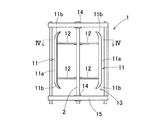
- a vertical axis windmill shown in FIGS. 4 and 5 is used.
- the vertical shaft type wind turbine 1 a plurality of blades 11 extending in the vertical direction around a main shaft 2 are attached via an arm 12 to form a blade wheel 13, and the main shaft 2 is supported by a frame 15 via a bearing 14.
- Each wing 11 is provided with winglets 11b at both upper and lower ends of the wing body 11a. Note that the main shaft 2 is shown in a horizontal posture in FIG.
- a table control device 5 is a device that controls output power according to a table 16 in which output power is set in advance with respect to an input voltage, and supplies output to a system 8, a battery (not shown), or the like.
- the table control device 5 is composed of a power conditioner or the like.
- the table control device 5 includes a power conversion unit 17 and a control unit 18 that controls the power conversion unit 17, and the table 16 is provided in the control unit 18.
- the power conversion unit 17 is a device that converts input DC or AC power into AC, and is mainly configured by an inverter, or a rectifier circuit and an inverter (both not shown).
- the alternating current to be output may be a single-phase alternating current or a three-phase alternating current.
- the control unit 18 controls the power conversion unit 17.
- the control unit 18 controls the power conversion unit 17 to output power according to the table 16.
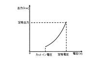
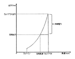
- the relationship between the voltage and the output shown in the graph in FIG. 2 is defined in the form of a table.
- the power circuit unit 21 is interposed between the generator 3 and the table control device 5.
- the table control device 5 may basically perform table control, and the output control device 4 may be bypassed to directly connect the generator 3 and the table control device 5. .
- the output control device 4 may change the voltage on the generator 3 side at a predetermined rate and use this as the input voltage to the table control device 5.
- the output control device 4 controls the power circuit unit 21 and the power circuit unit 21 having a rectifier circuit that converts an alternating current such as a three-phase alternating current generated by the generator 3 into a direct current. And a control unit 22.
- the power circuit unit 21 is a main circuit.
- the power circuit unit 21 may include an inverter (not shown) that converts the rectified DC power into single-phase AC power after the rectifier circuit.
- a resistor 6 and a battery 7 are connected to the power circuit unit 21.
- the resistor 6 and the battery 7 may be shared with the resistor and the battery connected to the table control device 5 or may be separate.
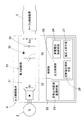
- FIG. 6 shows an example of the power circuit unit 21.
- the power circuit unit 21 in FIG. 1 is a chopper circuit, and a switching element 33 such as a switching transistor and a capacitor 34 are connected in parallel between a positive side line 31 and a ground side line 32.
- a diode 35 is provided between the switching element 33 and the capacitor 34 in FIG.
- Output power and input voltage can be controlled by controlling switching of the switching element 33 by PWM control or the like.
- the control unit 22 of the output control device 4 includes a rated output excess monitoring means 23, a generated voltage control means 24, and a rated voltage holding means 26.
- the generated voltage control means 24 and the rated voltage holding means 26 constitute an output processing unit 28.
- the output processing unit 28 may include a voltage raising unit 27 described later.
- the rated output excess monitoring means 23 includes any one of the rotational speed of the windmill 1 detected by the detector 25, the rotational speed of the generator 2, the wind speed, the generated voltage of the generator 3, and the generated power of the generator 3. Or one or more.
- the rated output excess monitoring means 23 estimates the output power of the output control device 5 based on this input.
- the rated output excess monitoring means 23 detects that the estimated power exceeds a specified value (for example, rated output) of the table control device 5. Instead, at least one of the characteristics of the rotational speed of the windmill 1, the rotational speed of the generator 2, the wind speed, the generated voltage of the generator 3, and the generated power of the generator 3 is compared with the specified value corresponding to each. Then, it may be determined whether or not at least one characteristic exceeds a corresponding specified value.
- the generated voltage control means 24 is means for reducing the generated voltage of the generator 3 by controlling the power circuit unit 21 when the rated output excess monitoring means 23 detects that the generator 3 has exceeded the rated output. is there.
- control for lowering the generated voltage control for lowering the input voltage of the power circuit unit 21, control for increasing the input resistance of the power circuit unit 21, or the like can be employed.
- the power circuit unit 21 is the chopper circuit described above with reference to FIG. 6, for example, the power generation voltage of the generator 3 is decreased by increasing the input voltage as described later with reference to FIG. 7.
- the rated voltage holding means 25 When the rated voltage holding means 25 detects that the rated output is exceeded by the rated output excess monitoring means 23, the rated voltage holding means 25 sets the input voltage to the table control device 5 to a voltage equal to or higher than the rated voltage set by the table control device 5. It is means to hold. A specific example of the rated voltage holding means 26 will be described later with reference to FIG.
- the voltage increasing means 27 is a means for increasing the voltage input to the table control device 5 when the voltage input from the generator 3 is equal to or lower than the set voltage.
- the output power of the table control device 5 is set to the rated output (see FIG. 3) based on information obtained from the detector 25 such as the rotational speed, input energy, and anemometer. It is detected by the rated output excess monitoring means 23 that it exceeds (shown). When the rated output is exceeded, the voltage of the generator 3 is lowered by the generated voltage control means 24. Thereby, the rotation speed of the windmill 1 is reduced, the state where the efficiency of the blades of the windmill 1 is intentionally poor is created, the increase in surplus output is suppressed, and the rated output is maintained.
- This output control device 3 is connected to the resistor 6 that consumes a part of the output or to the battery 7 when it is stored, and can cope with a case where a little surplus power is generated.
- the rated voltage holding means 26 causes the output control device 4 to change the input voltage of the table control device 5 (that is, the output voltage of the output limiting device 4) according to the table 16. Maintain a constant voltage higher than the rated voltage set by table control. Thus, it is possible to suppress the generation of surplus power and to always supply the rated output to the system 8, the battery 7, and the like. With these table control device 5 and output control device 4, even when the rated output is exceeded, surplus power can be suppressed without reducing the supply output to the system 8 and the battery 7, and the generator 3, the main shaft 2, its support portion, etc. The capacity of the machine body can be reduced.
- an output control device 4 is separately provided between the generator 3 and the table control device 5.
- table control may be basically performed by the table control device 5 up to the rated output of the table control device 5, and the generator 3 and the table control device 5 may be directly connected by bypassing the output control device 4.
- the output control device 4 may change the voltage on the generator 3 side at a predetermined rate and use this as the input voltage to the table control device 5.
- This control is performed by the output processing unit 28, specifically, for example, by the generated voltage control means 24.
- the table control device 5 often has a lower limit on the cut-in voltage, that is, the voltage corresponding to the cut-in wind speed.
- the cut-in wind speed can be decreased. Therefore, it is possible to generate power even with a slight wind.
- the windmill 2 is a vertical axis windmill, power generation is possible even at a relatively slow wind speed, but in combination with the control for reducing the cut-in wind speed, power generation with a light wind is more easily performed.
- the output control device 4 it is possible to suppress surplus power when the rating is exceeded. Moreover, in order to catch this surplus electric power, it is not necessary to set the capacity of the generator, the speed increaser, the spindle unit, etc. beyond the rated capacity, and it is possible to reduce the size of the generator, the speed increaser, the spindle unit, etc.
- the power circuit unit 21 shown in FIG. 6 is a general boost chopper circuit.
- the output processing unit 28 of the output control device 4 for example, the power generation voltage control means 24, particularly the generator 3 side until the rated power is exceeded. In addition, it should not contribute to the table controller side.
- FIG. 7 is an example of power control by the generated voltage control means 24 in the output control device 4.
- MPPT control is a method of searching for the maximum efficiency point by changing the voltage by the hill-climbing method.
- MPPT control may be employed, but the example of FIG. 7 is a method of searching for a target voltage by varying the input voltage.
- step S1 When an excess of the specified value is detected, the input voltage Ei is decreased by a constant value ⁇ E (step S1).
- the detected power P i when the rotation of the generator 3 is stalled is compared with the target power P ref set as a target, and when the detected power P i is larger (the result of step S2 is P i > P ref ), and further decreased by the constant value ⁇ E (step S3).
- the detected power ⁇ P i is smaller than the target power P ref (the result of step S2 is P ref > P i )
- the constant value ⁇ E is added to the input voltage E i (step S6).
- the input power detection value P i is substituted for the target power P ref (step S4), and the input voltage E i is maintained (step S5).
- the power when the voltage is lowered and stalled is compared with the power set as the target, and the voltage decrease is repeated until the detected power reaches the power set as the target. Further, in this case, the power is increased when the power becomes lower than the target power. By constantly repeating these, control is performed so that the power set as a target is constant.
- the voltage drop may be implemented by specifying the amount dE i / dt (so-called deceleration) in advance. This dE i / dt is obtained in advance through a test or the like.
- variable control of the input voltage can be realized without the table controller 5 such as a power conditioner.
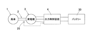
- the output of the output control device 4 may be connected to the battery 30.
- FIG. 8 is an example in which the output voltage is made constant by PI control (proportional integral control).
- a target current is calculated and compared with the actually measured output current detection value Io.
- the manipulated variable is determined by PI control by the output current control unit 43, the voltage to be boosted is determined by the voltage command unit 44, the duty ratio is determined based on this, and the output voltage is determined.
- the PWM control unit 45 controls the switching element 33 of the power circuit unit 21 to be opened and closed by PWM control. The ability to increase and vary the output voltage according to the time ratio is the same as the control when there is no excess of the specified value.
- the target value of the output voltage may be varied by increasing the output voltage by patterning in advance.
- this patterning for example, as shown in FIG. 9, an output voltage characteristic is preset with respect to a wind speed value.
Landscapes
- Engineering & Computer Science (AREA)
- Power Engineering (AREA)
- Control Of Eletrric Generators (AREA)
Abstract
テーブル制御装置における定格超過時の余剰電力の抑制を可能とし、これにより、余剰電力を受け止めるための、発電機や増速機、主軸ユニット等を定格以上の容量とするなどの対策が不要で、これらの小型化が図れる風力発電装置の出力制御装置を提供する。発電機(3)とテーブル制御装置(5)の間に介在する出力制御装置(4)である。風車(1)の回転数、発電機(3)の回転数または出力電圧、出力電流、および風速のうちのいずれかが入力されて、テーブル制御装置(5)の出力電力が定格出力を超過したことを監視する定格出力超過監視手段(23)を備える。定格出力を超過したことが推定されると発電機(3)の発電電圧を低下させる発電電圧制御手段(24)を備える。
Description
本出願は、2017年4月3日出願の特願2017-073491の優先権を主張するものであり、その全体を参照により本願の一部をなすものとして引用する。
この発明は、風力発電装置における出力制御装置であって、余剰電力の抑制を行う、風力発電装置の出力制御装置に関する。
風力発電装置では、風車の主軸に接続された発電機の負荷を、制御装置により風速に応じて変化させて、発電機のトルクを調整し、風車の出力制御を行っている(例えば、特許文献1)。風車の制御では、応答性の観点から、入力電圧に対する出力を予めテーブルに設定して、出力を制御するテーブル制御が多い。また、市販品のパワーコンディショナにはテーブル制御機能が内蔵されているものが出回っている。
上記のように、風車の出力の制御に、パワーコンディショナによるテーブル制御が用いられているが、定格に設定した出力を超過すると、それ以上の電力を系統に供給することができなくなるが、パワーコンディショナ等のテーブル制御装置の入力電圧の上昇が発生し結果として風車の回転上昇を生じてさせてしまう。そのため、電圧上昇を抑制しこの余剰電力を消費させる電力消費ユニットが必要である。またこの余剰分も考慮した大きな容量の発電機や増速機や主軸ユニットが必要である。
具体的には、固定翼等で定格出力以上の風によるエネルギーを吸収する機構がない風車では、図11に示すように、定格出力を超過するとそれ以上の電力を系統に供給することができなくなる。このため、このテーブル制御装置に基づくと入力電圧の上昇が発生し結果として風車の回転上昇を生じさせてしまう。そのため、この余剰電力を消費させる電力消費ユニットが必要である。また、この余剰分も考慮した大きな容量の発電機や増速機や主軸ユニットが必要であり、カットアウト風速を大きくしようとすると発電機等の容量を上げなければならない。そのため、コストとの兼ね合いからカットアウト風速が制限される。
この発明の目的は、テーブル制御装置における定格超過時の余剰電力の抑制を可能とし、これにより、余剰電力を受け止めるための、発電機や増速機、主軸ユニット等を定格以上の容量とするなどの対策が不要で、これらの小型化が図れる風力発電装置の出力制御装置を提供することである。
以下、便宜上理解を容易にするために、実施形態の符号を参照して説明する。
この発明の風力発電装置の出力制御装置は、風のエネルギーを回転エネルギーに変換する風車1と、風車1の回転エネルギーを電気エネルギーに変換する発電機3とを備えた風力発電装置に設けられる出力制御装置4であって、
前記発電機4と負荷の間に介在する電力回路部21と、
この電力回路部21を制御する制御部22であって、
前記発電機3が出力する電圧もしくは電力、前記風車1もしくは発電機3の回転数、および風速のうちの少なくとも一つの検出値が入力されて、入力された前記少なくとも一つの検出値が対応する規定値を超過したことを検出する定格出力超過監視手段23、および
前記少なくとも一つの検出値の少なくともいずれ一つが前記対応する規定値を超過したことが検出されると前記発電機3の発電電圧を低下させる発電電圧制御手段24を有する制御部22とを備える。
前記発電機4と負荷の間に介在する電力回路部21と、
この電力回路部21を制御する制御部22であって、
前記発電機3が出力する電圧もしくは電力、前記風車1もしくは発電機3の回転数、および風速のうちの少なくとも一つの検出値が入力されて、入力された前記少なくとも一つの検出値が対応する規定値を超過したことを検出する定格出力超過監視手段23、および
前記少なくとも一つの検出値の少なくともいずれ一つが前記対応する規定値を超過したことが検出されると前記発電機3の発電電圧を低下させる発電電圧制御手段24を有する制御部22とを備える。
この構成によると、発電機3の出力に関与する検出値が規定値を超過することが前記定格出力超過監視手段23により検出されると、発電電圧制御手段24は、前記発電機3の発電電圧を低下させるように前記電力回路部21を制御する。この発電電圧を低下させる制御は、前記電力回路部21の入力電圧を低下させる制御であっても、電力回路部21の入力抵抗を増大させる制御であってもよい。このように発電機3の電圧を低下させることで、その結果として風車1の回転が低下し、意図的に風車羽根の効率が悪い状況を作り出して定格出力を維持することができる。これにより、発電機3の余剰電力を受け止めるための、発電機3や増速機、主軸ユニット等を定格以上の容量とするなどの対策が不要で、これらの小型化を図ることができる。
なお、前記「規定値」は、前記電圧、電力、回転数、および風速それぞれにつき適宜定められる値である。例えば、前記発電機3の定格出力に対応する電圧、電力、回転数、風速等の値とされる。回転数や風速が高い場合、発電機3が定格出力を超えると推定されるため、前記定格出力における前記回転数や風速が前記規定値として定められる。
前記風力発電装置が、さらに、入力電圧と出力電力の関係が定められたテーブルに従って出力電力を制御するテーブル制御装置5であって前記発電機3と系統8の間に介在するテーブル制御装置5を備え、前記電力回路部21は前記発電機3と前記テーブル制御装置5との間に介在してもよい。
テーブル制御装置5を用いた風力発電装置では、定格に設定した出力を超過すると、それ以上の電力を系統8に供給することができなくなるが、テーブル制御装置5の入力の電圧上昇が発生してしまう。これにつき、前記テーブル制御装置5と発電機3の間に定格以上の電圧に対して調整を行う出力制御装置4を介在させることで、風車1の過回転を抑制することができる。
また、定格出力以上のさらなる風速超過による出力上昇に対応するため、この出力制御装置5の発電電圧制御手段24では、発電機3の電圧を低下させ、その結果として風車1の回転を低下させて意図的に風車羽根の効率が悪い状況を作り出し定格出力を維持する。
前記制御部22が、さらに、前記定格出力超過監視手段23により前記発電機3の出力が定格出力を超過したことが検出されると、前記テーブル制御装置5への入力電圧を、前記テーブル制御装置5で設定されている定格電圧以上の電圧に保持する定格電圧保持手段26を有していてもよい。
定格電圧保持手段26は、テーブル制御装置5で定格出力を維持するために、テーブル制御装置5への入力電圧をテーブル制御で設定した定格電圧より高い電圧、例えば一定電圧として保持する。これにより余剰電力の発生を抑制するとともに系統8には常に定格出力を供給することが可能となる。
前記発電機3から当該出力制御装置4に入力される電圧が設定電圧以下である場合に、前記テーブル制御装置5へ入力する電圧を上昇させる電圧上昇手段27を備えていてもよい。
テーブル制御装置5では、カットイン電圧に下限の制限があることが多いが、テーブル制御装置5に入力する電圧を上昇させることによりカットイン風速を低下させることが可能になる。これにより、より微小な風速の場合にも系統8に発電電力を供給することができる。
さらに、余剰電力を消費する抵抗6および余剰電力を蓄電するバッテリー7のいずれか一方または両方を備えていてもよい。これにより、少しの余剰電力が発生した場合にも対応可能となる。
前記風車1が垂直軸風車であってもよい。垂直軸風車を用いた発電装置は、風向きにかかわらず回転が生じ、また比較的小型の風車にも適用し易い。小型の風力発電装置の場合、複雑な制御装置を備えることは、コスト面から実用的でない。そのため、垂直軸風車を用いた風力発電装置にこの発明の出力制御装置4を適用することで、この発明の効果が、十分に発揮される。
請求の範囲および/または明細書および/または図面に開示された少なくとも2つの構成のどのような組合せも、本発明に含まれる。特に、請求の範囲の各請求項の2つ以上のどのような組合せも、本発明に含まれる。
この発明は、添付の図面を参考にした以下の好適な実施形態の説明から、より明瞭に理解されるであろう。しかしながら、実施形態および図面は単なる図示および説明のためのものであり、この発明の範囲を定めるために利用されるべきものではない。この発明の範囲は添付の請求の範囲によって定まる。添付図面において、複数の図面における同一の符号は、同一または相当する部分を示す。
この発明の第1の実施形態に係る出力制御装置を備えた風力発電装置の概念構成を示すブロック図である。
図1の風力発電装置のテーブル制御装置のテーブルの内容例を示すグラフである。
図1の出力制御装置を用いた場合のテーブル制御装置の風速と出力の関係例を示すグラフである。
垂直型風車の一例を示す正面図である。
図4のV-V線断面図である。
図1の出力制御装置における電力回路部の具体例を示す電気回路およびブロック図である。
図1の出力制御装置における発電電圧制御手段が行う処理を示す流れ図である。
図1の出力制御装置における定格電圧保持手段の具体例を示すブロック図である。
図1の出力制御装置における風力に対する出力の例を示すグラフである。
この発明の第2の実施形態に係る出力制御装置を備えた風力発電装置の概念構成を示すブロック図である。
従来例の風速と出力の関係例を示すグラフである。
この発明の第1の実施形態を図1ないし図9と共に説明する。図1は、この出力制御装置を備えた風力発電装置の一例を示す。この風力発電装置は、風のエネルギーを回転エネルギーに変換する風車1と、風車1の主軸2にカップリング(図示せず)等で連結されて風車2の回転エネルギーを電気エネルギーに変換する発電機3と、この発電機3と系統8の間に介在するテーブル制御装置5とを備える。前記発電機3とテーブル制御装置5との間に、この実施形態に係る出力制御装置4が介在する。発電機3は、例えば巻線型誘導発電機である。系統8は、発電電力を使用する負荷である。風車1と発電機3との間に増速機(図示せず)を備えていてもよい。
風車1は、垂直軸風車および水平軸風車(プロペラ型風車)のいずれでもよいが、この例では図4および5に一例を示す垂直軸型風車が用いられている。この垂直軸型の風車1は、主軸2の回りに上下方向に延びる複数の翼11がアーム12を介して取付けられて翼車13を構成し、主軸2が軸受14を介してフレーム15に支持されている。各翼11は、翼本体11aの上下両端にウイングレット11bが設けられている。なお、主軸2は、図1では模式化のために水平姿勢で図示している。
図1において、テーブル制御装置5は、予め入力電圧に対して出力電力が設定されたテーブル16に従って出力電力を制御し系統8やバッテリー(図示せず)等に出力を供給する装置である。テーブル制御装置5はパワーコンディショナ等で構成される。テーブル制御装置5は、電力変換部17とこの電力変換部17を制御する制御部18とを有し、この制御部18に前記テーブル16が設けられている。前記電力変換部17は、入力される直流または交流の電力を交流に変換する装置であり、主にインバータにより、または整流回路とインバータ(いずれも図示せず)により構成されている。出力する交流は、単相交流であっても、三相交流であってもよい。前記制御部18は、前記電力変換部17を制御する。例えば、制御部18は、前記テーブル16に従う電力を出力するように電力変換部17を制御する。このテーブル16は、例えば図2にグラフで示す電圧と出力の関係がテーブルの形式で定められている。
出力制御装置4は、その電力回路部21が発電機3とテーブル制御装置5の間に介在する。ただし、テーブル制御装置5の定格出力までは基本的にはテーブル制御装置5によりテーブル制御を行わせ、出力制御装置4をバイパスさせて発電機3とテーブル制御装置5間を直接接続させてもよい。代わりに、出力制御装置4は発電機3側の電圧を所定の割合で変化させて、これをテーブル制御装置5への入力電圧としてもよい。
出力制御装置4は、その電力回路部21が、発電機3の発電した三相交流等の交流電流を直流に変換する整流回路等を有する電力回路部21と、この電力回路部21を制御する制御部22とを有している。前記電力回路部21は、いわば主回路である。前記電力回路部21には、前記整流回路の後段に、整流された直流電力を単相交流電力に変換するインバータ(図示せず)を備えていてもよい。また、前記電力回路部21には抵抗6とバッテリー7とが接続されている。これら抵抗6とバッテリー7とは、テーブル制御装置5に接続される抵抗およびバッテリーと兼用されてもよく、また別々であってもよい。
図6は、電力回路部21の一例を示す。同図の電力回路部21は、チョッパー回路であり、正側ライン31とアース側ライン32との間に、スイッチングトラジスタ等のスイッチング素子33とコンデンサ34とが並列に接続され、正側ライン31におけるスイッチング素子33とコンデンサ34との間にダイオード35が設けられている。スイッチング素子33をPWM制御等での開閉制御することで、出力電力や入力電圧の制御が可能である。
図1において、出力制御装置4の制御部22には、定格出力超過監視手段23と、発電電圧制御手段24と、定格電圧保持手段26とを備える。前記発電電圧制御手段24および定格電圧保持手段26により出力処理部28が構成される。出力処理部28は、後述の電圧上昇手段27を有していてもよい。
定格出力超過監視手段23には、検出器25により検出される風車1の回転数、発電機2の回転数、風速、発電機3の発電電圧、および発電機3の発電電力のうちのいずか1つまたは複数が入力される。定格出力超過監視手段23は、この入力に基づいて出力制御装置5の出力電力を推定する。定格出力超過監視手段23は、推定電力がテーブル制御装置5の規定値(例えば定格出力)を超過したことを検出する。代わりに、前記風車1の回転数、発電機2の回転数、風速、発電機3の発電電圧、および発電機3の発電電力からなる特性の少なくとも一つと、それぞれに対応する規定値とを比較して、少なくとも一つの特性がその対応する規定値を超過したか否かを判定するようにしてもよい。
発電電圧制御手段24は、定格出力超過監視手段23により発電機3が定格出力を超過したことが検出されると、電力回路部21を制御することにより発電機3の発電電圧を低下させる手段である。発電電圧を低下させる制御としては、電力回路部21の入力電圧を低くする制御や、電力回路部21の入力抵抗を大きくする制御等が採用できる。電力回路部21が図6を参照して前述したチョッパー回路である場合は、例えば、図7を参照して後述するように入力電圧を高くすることで発電機3の発電電圧を低下させる。
定格電圧保持手段25は、定格出力超過監視手段23により定格出力を超過したことが検出されると、テーブル制御装置5への入力電圧を、テーブル制御装置5で設定されている定格電圧以上の電圧に保持する手段である。定格電圧保持手段26については、後に図8を参照して具体例を説明する。
電圧上昇手段27は、発電機3から入力される電圧が設定電圧以下である場合に、テーブル制御装置5へ入力する電圧を上昇させる手段である。
この構成の出力制御装置4によると、検出器25により得られる発電機3の回転数や入力エネルギー、風速計等からの情報に基づいて、テーブル制御装置5の出力電力が定格出力(図3に示す)を超過したことを定格出力超過監視手段23によって検出する。定格出力を超過したときは、発電電圧制御手段24により発電機3の電圧を低下させる。これにより、風車1の回転数を低下させ、意図的に風車1の羽根の効率が悪い状態を作り出し、余剰出力の上昇を抑制して定格出力を維持する。この出力制御装置3は、出力の一部を消費させる抵抗6や貯蓄させるやバッテリー7に接続されており、少しの余剰電力が発生した場合に対応可能である。
また、テーブル制御装置5で定格を維持するために、定格電圧保持手段26は、出力制御装置4によりテーブル制御装置5の入力電圧(すなわち、出力制限装置4の出力電圧)を、テーブル16に従い、テーブル制御で設定した定格電圧より大きい一定電圧に保持する。これにより余剰電力の発生を抑制するとともに、系統8やバッテリー7等へ常に定格出力を供給することが可能となる。これらテーブル制御装置5および出力制御装置4により、定格出力を超過した場合でも、系統8やバッテリー7への供給出力を減らすことなく余剰電力を抑制でき、発電機3や主軸2やその支持部などの機械体の容量を低下させることが可能になる。
この構成において、発電機3とテーブル制御装置5の間に別途に出力制御装置4を設けている。ただし、テーブル制御装置5の定格出力までは基本的にテーブル制御装置5によりテーブル制御を行わせ、出力制御装置4をバイパスさせて発電機3とテーブル制御装置5間を直接接続させてもよい。代わりに、出力制御装置4は発電機3側の電圧を所定の割合で変化させて、これをテーブル制御装置5への入力電圧としてもよい。この制御は出力処理部28で行い、具体的には、例えば発電電圧制御手段24が行う。図2に示すように、テーブル制御装置5では、カットイン電圧つまりカットイン風速に対応する電圧に下限の制限があることが多い。これに対して、電圧上昇手段27によりテーブル制御装置5に入力する電圧を上昇させることにより、カットイン風速を低下させることが可能になる。そのため、微風によっても発電が可能となる。風車2が垂直軸風車である場合、比較的に遅い風速であっても発電が可能であるが、前記カットイン風速を低下させる制御と相まって、より一層微風での発電が行われ易くなる。
このように、出力制御装置4を設けることにより、定格超過時の余剰電力の抑制が可能となる。また、この余剰電力を受け止めるために、発電機や増速機、主軸ユニット等を定格以上の容量とすることが不要で、これら発電機や増速機、主軸ユニット等の小型化が図れる。
上記実施形態につき、より具体的に説明する。
<定格電力超過前の説明>
図6に示した電力回路部21は、一般的な昇圧チョッパー回路である。時比率Dを一定に制御するか、または時比率D=0とすることにより、この出力制御装置4の出力処理部28、例えば発電電圧制御手段24は、定格電力超過までは特に発電機3側にもテーブル制御装置側にも寄与させないようにする。
図6に示した電力回路部21は、一般的な昇圧チョッパー回路である。時比率Dを一定に制御するか、または時比率D=0とすることにより、この出力制御装置4の出力処理部28、例えば発電電圧制御手段24は、定格電力超過までは特に発電機3側にもテーブル制御装置側にも寄与させないようにする。
テーブル制御装置5へ入力電圧を上昇させることにより、カットイン風速を低下させる効果が得られる。
<各規定値超過の検出例>
風速超過等は、次式を用いて検出できる。
Pi=(1/2)×(ρCpAV3η)
ここで、
Pi:入力電力
ρ:空気密度
Cp:羽効率
A:受風面積
V:風速
Pi=Vi×Iiであり、
Vi:入力電圧
Ii:入力電流
風速超過等は、次式を用いて検出できる。
Pi=(1/2)×(ρCpAV3η)
ここで、
Pi:入力電力
ρ:空気密度
Cp:羽効率
A:受風面積
V:風速
Pi=Vi×Iiであり、
Vi:入力電圧
Ii:入力電流
<規定値超過後の制御の説明>
図7は、この出力制御装置4における発電電圧制御手段24による電力制御の一例である。類似の制御方式としては、MPPT制御がある。MPPT制御方式は、電圧を山登り法により可変させて最大効率点を探す方法である。MPPT制御を採用してもよいが、図7の例は、入力電圧を可変させて目標電圧を探す方式である。
図7は、この出力制御装置4における発電電圧制御手段24による電力制御の一例である。類似の制御方式としては、MPPT制御がある。MPPT制御方式は、電圧を山登り法により可変させて最大効率点を探す方法である。MPPT制御を採用してもよいが、図7の例は、入力電圧を可変させて目標電圧を探す方式である。
規定値超過が検出されると、入力電圧Eiを一定値ΔEだけ低下させる(ステップS1)。これにより発電機3の回転を失速させた場合の検出された電力Piと目標として設定された目標電力Prefとを比較し、検出電力Piの方が大きい場合(ステップS2の結果がPi>Pref)、さらに前記一定値ΔEだけ低下させる(ステップS3)。検出電力ΔPiが目標電力Prefよりも小さくなっている場合(ステップS2の結果がPref>Pi)は、前記一定値ΔEを入力電圧Eiに加算する(ステップS6)。これらの処理の後、目標電力Prefに入力電力検出値Piを代入し(ステップS4)、入力電圧Eiを維持する(ステップS5)。
このように、電圧低下させて失速させた場合の電力と、目標として設定する電力とを比較し、検出電力が目標として設定する電力になるまで電圧低下を繰り返す。また、この場合、目標として設定する電力以下になった場合は、電力を増加させる。これらを常に繰り返すことにより、目標として設定する電力を一定とするように制御をする。
上記は一例であり、代わりに、電圧低下については予めその量dEi/dt(いわゆる減速度)を指定して実施してもよい。このdEi/dtは、事前に試験等を通して求めておく。
なお、入力電圧の可変制御については、パワーコンディショナ等のテーブル制御装置5がなくても実現が可能である。例えば、図10に第2の実施形態を示すように、この出力制御装置4の出力をバッテリー30に接続するようにしてもよい。
<出力電圧一定の制御(定格電圧保持手段26の制御)>
図8は、PI制御(比例積分制御)により出力電圧を一定にする例である。
図8は、PI制御(比例積分制御)により出力電圧を一定にする例である。
入力電力制御により得られた入力電力Piを除算部41で出力電圧の目標値Vorefで除することにより、目標となる電流を算出し、それを実測の出力電流検出値Ioと比較して出力電流制御部43によるPI制御で操作量を決定し、昇圧させる電圧を電圧指令部44で決定し、それに基づき時比率を決定し、出力電圧を決定する。前記時比率に従い、PWM制御部45で電力回路部21のスイッチング素子33をPWM制御で開閉制御する。時比率により出力電圧を増加可変させることが可能なことは、規定値超過がない場合における制御と同様である。
出力電圧の目標値に関して、事前にパターン化することにより出力電圧を上昇させるなどして可変させてもよい。このパターン化の例は、例えば図9に示すように、風速値に対して出力電圧特性を予め設定することなどが挙げられる。
以上のとおり、図面を参照しながら好適な実施形態を説明したが、本発明の趣旨を逸脱しない範囲内で、種々の追加、変更または削除が可能である。したがって、そのようなものも本発明の範囲内に含まれる。
1:風車
3:発電機
4:出力制御装置
5:テーブル制御装置
21…電力回路部
22…制御部
23…定格出力超過監視手段
24:発電電圧制御手段
3:発電機
4:出力制御装置
5:テーブル制御装置
21…電力回路部
22…制御部
23…定格出力超過監視手段
24:発電電圧制御手段
Claims (6)
- 風のエネルギーを回転エネルギーに変換する風車と、
前記風車の回転エネルギーを電気エネルギーに変換する発電機とを備えた風力発電装置に設けられる出力制御装置であって、
前記発電機と負荷の間に介在する電力回路部と、
この電力回路部を制御する制御部であって、
前記発電機が出力する電圧もしくは電力、前記風車もしくは前記発電機の回転数、および風速のうちの少なくとも一つの検出値が入力されて、入力された前記少なくとも一つの検出値が対応する規定値を超過したことを検出する定格出力超過監視手段、および
前記少なくとも一つの検出値の少なくともいずれ一つが前記対応する規定値を超過したことが検出されると前記発電機の発電電圧を低下させる発電電圧制御手段を有する制御部とを備える風力発電装置の出力制御装置。 - 請求項1に記載の風力発電装置の出力制御装置において、前記風力発電装置が、さらに、入力電圧と出力電力の関係が定められたテーブルに従って出力電力を制御するテーブル制御装置であって前記発電機と系統の間に介在するテーブル制御装置を備え、前記電力回路部は前記発電機と前記テーブル制御装置との間に介在する風力発電装置の出力制御装置。
- 請求項2に記載の風力発電装置の出力制御装置において、前記制御部が、さらに、
前記定格出力超過監視手段により前記発電機の出力が定格出力を超過したことが検出されると、前記テーブル制御装置への入力電圧を、前記テーブル制御装置で設定されている定格電圧以上に保持する定格電圧保持手段を有する風力発電装置の出力制御装置。 - 請求項1または請求項2に記載の風力発電装置の出力制御装置において、前記制御部が、さらに、
前記発電機から当該出力制御装置に入力される電圧が設定電圧以下である場合に、前記テーブル制御装置へ入力する電圧を上昇させる電圧上昇手段を備える風力発電装置の出力制御装置。 - 請求項1ないし請求項4のいずれか1項に記載の風力発電装置の出力制御装置において、さらに、余剰電力を消費する抵抗および余剰電力を蓄電するバッテリーのいずれか一方または両方を備える風力発電装置の出力制御装置。
- 請求項1ないし請求項5のいずれか1項に記載の風力発電装置の出力制御装置において、前記風車が垂直軸風車である風力発電装置の出力制御装置。
Applications Claiming Priority (2)
| Application Number | Priority Date | Filing Date | Title |
|---|---|---|---|
| JP2017073491A JP6997530B2 (ja) | 2017-04-03 | 2017-04-03 | 風力発電装置の出力制御装置 |
| JP2017-073491 | 2017-04-03 |
Publications (1)
| Publication Number | Publication Date |
|---|---|
| WO2018186263A1 true WO2018186263A1 (ja) | 2018-10-11 |
Family
ID=63713034
Family Applications (1)
| Application Number | Title | Priority Date | Filing Date |
|---|---|---|---|
| PCT/JP2018/012876 Ceased WO2018186263A1 (ja) | 2017-04-03 | 2018-03-28 | 風力発電装置の出力制御装置 |
Country Status (2)
| Country | Link |
|---|---|
| JP (1) | JP6997530B2 (ja) |
| WO (1) | WO2018186263A1 (ja) |
Citations (4)
| Publication number | Priority date | Publication date | Assignee | Title |
|---|---|---|---|---|
| JP2006149055A (ja) * | 2004-11-18 | 2006-06-08 | Ntt Power & Building Facilities Inc | 風力発電設備の運転制御方法及び運転制御装置、ならびに、コンピュータプログラム |
| JP2007195315A (ja) * | 2006-01-18 | 2007-08-02 | Fukuoka Institute Of Technology | 風力発電システムの運転制御方法及びその装置 |
| JP2008017683A (ja) * | 2006-06-05 | 2008-01-24 | Yaskawa Electric Corp | 風力発電装置の発電機制御方法およびその装置 |
| JP2013158192A (ja) * | 2012-01-31 | 2013-08-15 | Minoru Murano | 発電出力の適正制御方法 |
-
2017
- 2017-04-03 JP JP2017073491A patent/JP6997530B2/ja active Active
-
2018
- 2018-03-28 WO PCT/JP2018/012876 patent/WO2018186263A1/ja not_active Ceased
Patent Citations (4)
| Publication number | Priority date | Publication date | Assignee | Title |
|---|---|---|---|---|
| JP2006149055A (ja) * | 2004-11-18 | 2006-06-08 | Ntt Power & Building Facilities Inc | 風力発電設備の運転制御方法及び運転制御装置、ならびに、コンピュータプログラム |
| JP2007195315A (ja) * | 2006-01-18 | 2007-08-02 | Fukuoka Institute Of Technology | 風力発電システムの運転制御方法及びその装置 |
| JP2008017683A (ja) * | 2006-06-05 | 2008-01-24 | Yaskawa Electric Corp | 風力発電装置の発電機制御方法およびその装置 |
| JP2013158192A (ja) * | 2012-01-31 | 2013-08-15 | Minoru Murano | 発電出力の適正制御方法 |
Also Published As
| Publication number | Publication date |
|---|---|
| JP2018182775A (ja) | 2018-11-15 |
| JP6997530B2 (ja) | 2022-01-17 |
Similar Documents
| Publication | Publication Date | Title |
|---|---|---|
| EP2360375B1 (en) | Method for operating a power dissipating unit in a wind turbine | |
| DK2017473T3 (en) | Wind energy system with extended rpm range | |
| CN105144532B (zh) | 用于将电功率馈送到供电网中的方法 | |
| ES2989111T3 (es) | Sistema y procedimiento para optimizar la operación de turbinas eólicas | |
| CN100400862C (zh) | 支持电网的、具有无功功率模块的风力发电设备及其方法 | |
| US10968889B2 (en) | Wind turbine control | |
| CN105121841B (zh) | 用于控制风电厂的方法 | |
| CN101534013A (zh) | 风轮机能量存储及频率控制 | |
| EP2702684B1 (en) | A variable wind turbine having a power dissipating unit; a method of operating a power dissipating unit in a wind turbine | |
| CN103052793A (zh) | 风车的输出控制装置及输出控制方法 | |
| JP2019532206A (ja) | 風力タービン制御方法及びシステム | |
| JP2017145733A (ja) | 風力発電装置および風力発電装置の制御方法 | |
| JP2005269843A (ja) | 系統連系装置 | |
| CN105074203A (zh) | 风能设施和用于运行风能设施的方法 | |
| JP6310079B2 (ja) | 風力発電装置の制御方法 | |
| JP6559563B2 (ja) | 風力発電用の出力制御装置 | |
| WO2018186263A1 (ja) | 風力発電装置の出力制御装置 | |
| WO2020009065A1 (ja) | 風力発電装置の出力制御装置 | |
| Divya | Combination of super capacitor-switch type fault current limiter for LVRT enhancement of DFIG wind turbines | |
| JP4398440B2 (ja) | 風力発電装置 | |
| WO2018105232A1 (ja) | 風車制御装置 | |
| Muljadi et al. | Energy storage opportunities and capabilities of a type 3 wind turbine generator | |
| US20250230795A1 (en) | Method for controlling an electro-mechanical actuation system and electro-mechanical actuation system | |
| CN223599693U (zh) | 一种机载电机与控制器一体化结构 | |
| JP6611118B2 (ja) | 電力変換装置およびそれを用いた産業機械 |
Legal Events
| Date | Code | Title | Description |
|---|---|---|---|
| 121 | Ep: the epo has been informed by wipo that ep was designated in this application |
Ref document number: 18780912 Country of ref document: EP Kind code of ref document: A1 |
|
| NENP | Non-entry into the national phase |
Ref country code: DE |
|
| 122 | Ep: pct application non-entry in european phase |
Ref document number: 18780912 Country of ref document: EP Kind code of ref document: A1 |