WO2018186177A1 - 測距装置、測距方法、およびプログラム - Google Patents
測距装置、測距方法、およびプログラム Download PDFInfo
- Publication number
- WO2018186177A1 WO2018186177A1 PCT/JP2018/011249 JP2018011249W WO2018186177A1 WO 2018186177 A1 WO2018186177 A1 WO 2018186177A1 JP 2018011249 W JP2018011249 W JP 2018011249W WO 2018186177 A1 WO2018186177 A1 WO 2018186177A1
- Authority
- WO
- WIPO (PCT)
- Prior art keywords
- unit
- signal
- ofdm
- crosstalk
- ultrasonic
- Prior art date
- Legal status (The legal status is an assumption and is not a legal conclusion. Google has not performed a legal analysis and makes no representation as to the accuracy of the status listed.)
- Ceased
Links
Images









Classifications
-
- G—PHYSICS
- G01—MEASURING; TESTING
- G01S—RADIO DIRECTION-FINDING; RADIO NAVIGATION; DETERMINING DISTANCE OR VELOCITY BY USE OF RADIO WAVES; LOCATING OR PRESENCE-DETECTING BY USE OF THE REFLECTION OR RERADIATION OF RADIO WAVES; ANALOGOUS ARRANGEMENTS USING OTHER WAVES
- G01S15/00—Systems using the reflection or reradiation of acoustic waves, e.g. sonar systems
- G01S15/02—Systems using the reflection or reradiation of acoustic waves, e.g. sonar systems using reflection of acoustic waves
- G01S15/06—Systems determining the position data of a target
- G01S15/08—Systems for measuring distance only
- G01S15/32—Systems for measuring distance only using transmission of continuous waves, whether amplitude-, frequency-, or phase-modulated, or unmodulated
-
- H—ELECTRICITY
- H04—ELECTRIC COMMUNICATION TECHNIQUE
- H04B—TRANSMISSION
- H04B11/00—Transmission systems employing ultrasonic, sonic or infrasonic waves
-
- G—PHYSICS
- G01—MEASURING; TESTING
- G01S—RADIO DIRECTION-FINDING; RADIO NAVIGATION; DETERMINING DISTANCE OR VELOCITY BY USE OF RADIO WAVES; LOCATING OR PRESENCE-DETECTING BY USE OF THE REFLECTION OR RERADIATION OF RADIO WAVES; ANALOGOUS ARRANGEMENTS USING OTHER WAVES
- G01S15/00—Systems using the reflection or reradiation of acoustic waves, e.g. sonar systems
- G01S15/003—Bistatic sonar systems; Multistatic sonar systems
-
- G—PHYSICS
- G01—MEASURING; TESTING
- G01S—RADIO DIRECTION-FINDING; RADIO NAVIGATION; DETERMINING DISTANCE OR VELOCITY BY USE OF RADIO WAVES; LOCATING OR PRESENCE-DETECTING BY USE OF THE REFLECTION OR RERADIATION OF RADIO WAVES; ANALOGOUS ARRANGEMENTS USING OTHER WAVES
- G01S15/00—Systems using the reflection or reradiation of acoustic waves, e.g. sonar systems
- G01S15/02—Systems using the reflection or reradiation of acoustic waves, e.g. sonar systems using reflection of acoustic waves
- G01S15/06—Systems determining the position data of a target
- G01S15/08—Systems for measuring distance only
- G01S15/32—Systems for measuring distance only using transmission of continuous waves, whether amplitude-, frequency-, or phase-modulated, or unmodulated
- G01S15/325—Systems for measuring distance only using transmission of continuous waves, whether amplitude-, frequency-, or phase-modulated, or unmodulated using transmission of coded signals, e.g. of phase-shift keyed [PSK] signals
-
- H—ELECTRICITY
- H04—ELECTRIC COMMUNICATION TECHNIQUE
- H04B—TRANSMISSION
- H04B17/00—Monitoring; Testing
- H04B17/20—Monitoring; Testing of receivers
- H04B17/27—Monitoring; Testing of receivers for locating or positioning the transmitter
-
- H—ELECTRICITY
- H04—ELECTRIC COMMUNICATION TECHNIQUE
- H04L—TRANSMISSION OF DIGITAL INFORMATION, e.g. TELEGRAPHIC COMMUNICATION
- H04L27/00—Modulated-carrier systems
- H04L27/26—Systems using multi-frequency codes
Definitions
- the present technology relates to a distance measuring device, a distance measuring method, and a program, and in particular, a distance measuring device that irradiates an object with ultrasonic waves and measures the distance to the object based on the reflected wave, a distance measuring method, And program.
- the ultrasonic wave refers to a sound wave (elastic wave) having a frequency (frequency) that is high enough not to produce a sense of hearing for a person with normal hearing ability.
- FIG. 1 is a block diagram showing an example of a conventional configuration of a distance measuring apparatus employing a pulse echo method.
- the distance measuring device includes a transmission unit 1, a reception unit 2, a timer 11, an interface unit 9, and a control unit 10.
- the transmitting unit 1 includes an oscillating unit 3, a driving unit 4, and an ultrasonic speaker 5 (hereinafter abbreviated as a speaker 5).
- the receiving unit 2 includes an ultrasonic microphone 6 (hereinafter abbreviated as a microphone 6), an amplification detection unit 7, and a Schmitt trigger unit 8.
- ultrasonic waves are output from the speaker 5 of the transmission unit 1 toward an object whose distance is to be measured, and the reflected waves are collected by the microphone 6 of the reception unit 2.
- the electric signal corresponding to the reflected wave collected by the microphone 6 is amplified and detected by the amplification detection unit, the amplitude is compared with a predetermined threshold value by the Schmitt trigger unit 8, and the Schmitt trigger as the comparison result is displayed by the timer. 11 is supplied.
- the timer 11 measures the timing at which the ultrasonic wave is transmitted and the timing at which the reflection is collected, and outputs the measured timing to the control unit 10 via the interface unit 9.
- the control unit 10 calculates the time difference td between the two timings, and calculates the distance L to the object by applying the time difference td to the following equation (1).
- v is the ultrasonic velocity.
- L v ⁇ td / 2 (1)
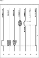
- FIG. 2 shows the timing of ultrasonic output, sound collection, etc. in the distance measuring apparatus of FIG.
- the oscillation unit 3 causes the measurement request pulse to be transmitted as shown in FIG. Is output to the drive unit 4.
- the drive unit 4 causes the speaker 5 to output ultrasonic waves by vibrating the speaker 5 in response to the ultrasonic signals.
- the ultrasonic wave output from the speaker 5 is distorted as shown in FIG. C due to its characteristics and environmental sound, and the waveform of the reflected wave from the object is further shown in FIG. It becomes distorted as shown.
- the Schmitt trigger unit 8 compares the amplitude of the reflected wave shown in FIG. D with a predetermined detection threshold as shown in FIG. E, and outputs a Schmitt trigger output as shown in FIG. 11 is supplied.
- the timer 11 notifies the control unit 10 of the timing at which the ultrasonic wave is transmitted, and detects the rising timing of the Schmitt trigger output shown in FIG. 10 is notified.
- the control unit 10 calculates a difference between both timings as a time difference td, and calculates a distance L to the object using the time difference td.
- the Schmitt trigger output depends on the detection threshold value in the Schmitt trigger circuit 8 if the amplitude of the collected reflected wave is attenuated or the setting of the detection threshold value is not appropriate, the Schmitt trigger output is performed. It is impossible to accurately detect the rising timing of the trigger output, that is, the timing at which the ultrasonic waves are collected. Therefore, in this case, an error occurs in the time difference td, and the accuracy of the distance L calculated based on the error is also reduced.
- the present technology has been proposed in view of such a situation, and enables the object to be accurately measured by detecting td, which is a time difference between ultrasonic transmission and reception timings, with high accuracy. is there.
- a distance measuring apparatus includes an OFDM modulation unit that generates an OFDM signal by performing OFDM modulation on a transmission signal, an output unit that outputs the OFDM signal as an ultrasonic wave, and the output Obtained in the process of generating the OFDM signal, a sound collecting unit that collects ultrasonic waves as reflected waves in the ultrasonic object as a received signal, a demodulator that generates a demodulated signal by demodulating the received signal A calculation unit that calculates a delay profile based on the own signal and the demodulated signal, a calculation unit that calculates a delay time of the ultrasonic wave from the delay profile, and calculates a distance to the object based on the delay time; Is provided.
- the distance measuring apparatus may further include a division unit that generates a transfer function by dividing the demodulated signal by the OFDM signal, and the calculation unit performs an inverse Fourier transform on the transfer function.
- the distance measuring device may further include an orthogonal modulation unit that performs orthogonal modulation of the OFDM signal before being conveyed by the ultrasonic wave, and the demodulation unit is orthogonal to the received signal.
- the demodulated signal can be generated by performing orthogonal demodulation corresponding to modulation and performing Fourier transform.
- the OFDM modulation unit can provide a guard interval for the OFDM signal.
- the OFDM modulation unit can provide the guard interval having the same length as the OFDM effective symbol length.
- the OFDM modulation unit can set the FFT size, which is a parameter in OFDM modulation, to a power of 2, and the number of carriers to be 1/2 of the FFT size.
- the distance measuring apparatus may further include a replica signal generation unit that generates a replica signal corresponding to a crosstalk component, and a subtraction unit that subtracts the replica signal from the reception signal.
- the distance measuring device may further include a crosstalk measurement unit that measures crosstalk information, and the replica signal generation unit generates the replica signal based on the crosstalk information. Can do.
- the crosstalk measurement unit can measure at least one of a delay time corresponding to the crosstalk, an attenuation of the amplitude of the OFDM signal, or a phase rotation as the crosstalk information.
- the crosstalk measurement unit can periodically update the crosstalk information.
- the crosstalk measurement unit can update the crosstalk information when a peak corresponding to crosstalk appears in the delay profile.
- a distance measuring device further includes a cancellation unit that corrects distortion of the reception signal caused by frequency characteristics of an ultrasonic speaker as the output unit and an ultrasonic microphone as the sound collection unit. be able to.
- the cancellation unit can be included in the OFDM modulation unit.
- the cancellation unit can multiply the inverse characteristics of the frequency characteristics of the ultrasonic speaker and the ultrasonic microphone in the process of generating the OFDM signal.
- a distance measuring method is a distance measuring method by a distance measuring device, wherein the distance measuring device generates an OFDM signal by performing OFDM modulation on a transmission signal, and the OFDM signal
- a demodulation step to generate, a calculation step to calculate a delay profile based on the own signal obtained in the process of generating the OFDM signal and the demodulated signal, a delay time of the ultrasonic wave from the delay profile, and the delay time And calculating a distance to the object on the basis of.
- a program is output to a computer, an OFDM modulation unit that generates an OFDM signal by performing OFDM modulation on a transmission signal, and an output unit that outputs the OFDM signal as an ultrasonic wave carrier Obtained in the process of generating the OFDM signal, a sound collecting unit that collects an ultrasonic wave as a reflected wave on the ultrasonic object as a received signal, a demodulator that generates a demodulated signal by demodulating the received signal, A calculation unit that calculates a delay profile based on the local signal and the demodulated signal, and a calculation unit that calculates a delay time of the ultrasonic wave from the delay profile and calculates a distance to the object based on the delay time To function as.
- an OFDM signal is generated by performing OFDM modulation on a transmission signal, the OFDM signal is output as an ultrasonic wave as a carrier wave, and an ultrasonic wave as a reflected wave in an object of the output ultrasonic wave is output.
- a sound wave is collected as a received signal, a demodulated signal is generated by demodulating the received signal, a delay profile is calculated based on the own signal and the demodulated signal obtained in the process of generating the OFDM signal, and the delay
- the ultrasonic delay time is obtained from the profile, and the distance to the object is calculated based on the delay time.
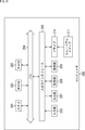
- FIG. 11 is a block diagram illustrating a configuration example of a general-purpose computer. It is a block diagram which shows an example of a schematic structure of a vehicle control system. It is explanatory drawing which shows an example of the installation position of a vehicle exterior information detection part and an imaging part.
- the distance measuring device to which the present technology is applied outputs ultrasonic waves when measuring the distance to an object, collects the reflected waves, and obtains the time required for transmission / reception of ultrasonic waves in order to obtain the conventional pulse echo. It is the same as the method. However, by transmitting and receiving ultrasonic waves as a carrier wave of an OFDM (Orthogonal Frequency Division Multiplexing) modulated signal (hereinafter referred to as an OFDM signal), the time required for transmission and reception of ultrasonic waves by calculation is reduced. Different points are required. Thereby, compared with the case where the Schmitt trigger output is obtained as in the prior art, the time required for transmission / reception of the ultrasonic wave can be obtained accurately, and the distance to the object can be calculated with high accuracy. .
- OFDM Orthogonal Frequency Division Multiplexing
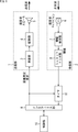
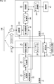
- FIG. 3 is a block diagram illustrating a configuration example of the distance measuring apparatus according to the first embodiment of the present technology.
- the first embodiment includes a transmission unit 21 that outputs ultrasonic waves toward an object 100, a reception unit 31 that collects reflected waves (reception signals) to obtain a transmission / reception timing time difference, and transmission / reception timing. It is comprised from the calculating part 41 which calculates the distance to the target object 100 based on this time difference.
- the transmission part 21 and the receiving part 31 shall be arrange
- the transmission unit 21 includes an OFDM modulation unit 22, an orthogonal modulation unit 25, a local oscillator 26, and an ultrasonic speaker 27 (hereinafter abbreviated as a speaker 27).
- the OFDM modulation unit 22 includes a digital modulation unit 23 and an inverse Fourier transform unit 24.
- the digital modulation unit 23 performs predetermined digital modulation on a transmission signal such as a rectangular wave, and outputs the phase and amplitude obtained as a result to the inverse Fourier transform unit 24.
- the phase and amplitude obtained as a result of the predetermined digital modulation are also notified to the division unit 35 of the reception unit 31 as a self signal.
- the inverse Fourier transform unit 24 generates an OFDM signal corresponding to the transmission signal by performing an inverse Fourier transform on the output of the digital modulation unit 23, adds a guard interval, and outputs the OFDM signal to the orthogonal modulation unit 25.
- FIG. 4 shows a timing chart when transmission / reception is performed by adding a guard interval to the OFDM signal.
- FIG. 7A shows transmission timing
- FIG. 6B shows reception timing.
- a guard interval between symbols of an OFDM signal by adding a guard interval between symbols of an OFDM signal, a signal to be transmitted / received becomes redundant, but it becomes possible to suppress the influence of multipath described later.
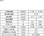
- FIG. 5 shows an example of parameters related to OFDM modulation in the OFDM modulator 22.
- it indicates the OFDM bandwidth, maximum detection distance, detection accuracy, carrier interval, number of carriers, FFT size, sampling frequency, OFDM symbol length, OFDM effective symbol length, and guard interval length.
- the OFDM bandwidth is set to 8.192 kHz or 16.384 kHz
- the OFDM bandwidth is not limited to these two types.
- the maximum detection distance, the carrier interval, the OFDM symbol length, and the OFDM effective symbol length are common regardless of the OFDM bandwidth, and the others are changed according to the OFDM bandwidth.
- the FFT (Fourier transform) size is set to a power of 2 and the number of carrier waves is set to 1 ⁇ 2 thereof.
- the number of carriers is 512
- the number of carriers at that time is 1024.
- the guard interval length is the same as the OFDM effective symbol length.
- interference between symbols can be prevented more effectively, and the delay time that can be acquired from the delay profile can be increased to the longest, and the maximum detection distance that represents the distance to the measurable object 100 can be increased. Can be extended to the longest.
- the orthogonal modulation unit 25 provides an OFDM signal supplied from the inverse Fourier transform unit 24 to which a guard interval is added, performs orthogonal modulation, and outputs from the speaker 27 as an ultrasonic wave centered on the carrier frequency f0.
- the local oscillator 26 supplies a clock signal having a carrier frequency f 0 to the quadrature modulation unit 25. It is assumed that the local oscillator 26 has previously notified the orthogonal frequency demodulator 33 of the receiver 31 about the carrier frequency f0.
- the receiving unit 31 includes an ultrasonic microphone 32 (hereinafter abbreviated as a microphone 32), an orthogonal demodulation unit 33, a Fourier transform unit 34, a division unit 35, and an inverse Fourier transform unit 36.
- the microphone 32 collects the ultrasonic wave output from the speaker 27 and reflected by the object 100 and outputs a corresponding reception signal to the orthogonal demodulation unit 33.
- the quadrature demodulation unit 33 performs quadrature demodulation corresponding to the quadrature modulation by the quadrature modulation unit 25 of the transmission unit 21 on the reception signal input from the microphone 32, and sends the resulting quadrature demodulation signal to the Fourier transform unit 34. Output. Since the orthogonal demodulator 33 holds information related to the carrier frequency f0 in advance, processing such as carrier wave reproduction can be omitted.
- the Fourier transform unit 34 performs a Fourier transform on the quadrature demodulated signal and outputs the result to the division unit 35.
- the division unit 35 calculates the transfer function of the reflected wave by dividing the result of the Fourier transform by the Fourier transform unit 34 by the own signal supplied from the OFDM modulation unit 22 of the transmission unit 21, thereby calculating the inverse Fourier transform unit. 36.
- the inverse Fourier transform unit 36 performs an inverse Fourier transform on the transfer function, and outputs a delay profile obtained as a result, which can acquire the time required for the transmission / reception time of the OFDM signal, to the calculation unit 41.
- the calculating unit 41 calculates the time difference td from the delay profile and applies it to the equation (1) to calculate the distance to the object 100.
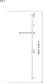
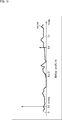
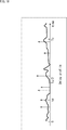
- FIG. 6 shows an example of a delay profile obtained by performing inverse Fourier transform on the transfer function.
- the calculation unit 41 can obtain the time required for the transmission / reception time of the OFDM signal by detecting the peak in the delay profile.
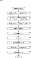
- FIG. 7 is a flowchart for explaining a transmission process performed by the transmission unit 21.
- step S1 in the transmission unit 21, the digital modulation unit 23 of the OFDM modulation unit 22 performs predetermined digital modulation on a transmission signal such as a rectangular wave, and the result is obtained.
- the phase and amplitude are output to the inverse Fourier transform unit 24.
- step S2 the inverse Fourier transform unit 24 performs an inverse Fourier transform on the output of the digital modulation unit 23 to generate an OFDM signal corresponding to the transmission signal, and further adds a guard interval to add the orthogonal modulation unit 25. Output to.
- step S3 the quadrature modulation unit 25 performs quadrature modulation on the OFDM signal provided with the guard interval supplied from the inverse Fourier transform unit 24, and outputs from the speaker 27 as an ultrasonic wave centered on the carrier frequency f0. Let The ultrasonic wave is reflected by the object 100.
- step S4 the reception unit 31 collects the reflected waves of the ultrasonic waves reflected by the object 100, and outputs a corresponding reception signal to the orthogonal demodulation unit 33.
- step S5 the reception signal input from the microphone 32 is subjected to orthogonal demodulation corresponding to the orthogonal modulation by the orthogonal modulation unit 25 of the transmission unit 21, and the resulting orthogonal demodulation signal is output to the Fourier transform unit 34.
- step S ⁇ b> 6 the Fourier transform unit 34 performs Fourier transform on the quadrature demodulated signal and outputs the result to the division unit 35.
- step S ⁇ b> 7 the division unit 35 calculates the transfer function of the reflected wave by dividing the result of the Fourier transform by the Fourier transform unit 34 by the own signal information supplied from the OFDM modulation unit 22 of the transmission unit 21. And output to the inverse Fourier transform unit 36.
- step S8 the inverse Fourier transform unit 36 performs inverse Fourier transform on the transfer function input from the division unit 35, and outputs the resulting delay profile to the calculation unit 41.
- step S9 the calculation unit 41 detects the time difference td from the delay profile, and calculates the distance to the object 100 by applying the time difference td to equation (1).
- the distance measuring apparatus does not use the Schmitt trigger output as in the pulse echo method, but obtains the transfer function by calculation, and obtains the delay profile from the transfer function.
- the time difference td is detected. Therefore, the time difference td can be obtained more accurately than in the pulse echo method, and the object 100 can be measured with high accuracy. Further, since the OFDM signal guard interval is provided, the influence of multipath can be reduced.
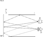
- FIG. 8 shows a case where multipath is generated in the ultrasonic wave output from the distance measuring apparatus according to the first embodiment of the present technology. That is, it is desirable that the path of the ultrasonic wave output from the speaker 27 reaches the object 100 directly from the speaker 27 and the reflected wave is directly collected by the microphone 32 as indicated by the solid line. .
- the speaker 27 may reflect the object other than the target object 100, or the reflected wave from the target object 100 may be reflected by another object, as shown by a broken line or a dashed line. Sound may be collected by the microphone 32.
- the path indicated by the broken line or the alternate long and short dash line is longer than the path indicated by the solid line, and therefore the timing at which the sound is collected by the microphone 32 is slower than the reflected wave of the path indicated by the solid line.
- FIG. 9 shows the output of ultrasonic waves and the timing of sound collection when multipath occurs as shown in FIG.
- the ultrasonic wave output at the timing shown in FIG. A is collected with a time difference td1 as shown in FIG.
- the sound is collected with a time difference td2 as shown in FIG.
- the sound is collected with a time difference td3 as shown in FIG.
- FIG. 10 shows a delay profile corresponding to the case shown in FIG.
- the time difference td appears as a peak corresponding to the time difference in the delay profile. That is, peaks corresponding to the time differences td1 and td2 appear in the delay profile. Therefore, it can be seen that if the time difference td is detected based on the delay profile, the multipath can be detected separately.
- the delay profile obtained this time is compared with the delay profile obtained immediately before, and based on the comparison result. Any one of the peaks may be selected according to a predetermined rule, and the time difference td used for calculating the distance L to the object 100 may be detected.
- FIG. 11 shows an example of a reflected wave in which the time difference td3 exceeds the guard interval length.
- the reflected wave collected over the guard interval length is in a state where inter-symbol interference occurs, resulting in disturbance to other reflected waves, and the delay time cannot be measured accurately.
- FIG. 12 shows the output of ultrasonic waves and the timing of sound collection when crosstalk occurs.
- FIG. 5A shows the output timing of the ultrasonic wave
- FIG. 5B shows the sound collection timing of the crosstalk
- FIG. 5B shows the sound collection timing of the reflected wave from the object 100.
- crosstalk components since the ultrasonic waves directly collected by the crosstalk (hereinafter referred to as crosstalk components) are not attenuated by distance or reflection, the object shown in FIG. The amplitude is larger than the reflected wave from 100.
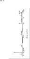
- FIG. 13 shows a delay profile corresponding to the case where the crosstalk shown in FIG. 12 occurs.
- FIG. 14 is a block diagram illustrating a configuration example of a distance measuring apparatus according to the second embodiment of the present technology.
- a function capable of removing a crosstalk component is added to the first embodiment described above.
- the distance measuring apparatus is obtained by adding a crosstalk measuring unit 61, a replica signal generating unit 62, and a subtracting unit 63 to the first embodiment shown in FIG. .
- Other components are the same as those in the first embodiment, and are given the same reference numerals, and the description thereof will be omitted as appropriate.
- the crosstalk measuring unit 61 is output from the inverse Fourier transform unit 24 by operating the distance measuring device in a state where the object 100 does not exist at the time of manufacture or the like and exists in a very far place.
- Crosstalk information (time difference td_cross, attenuation of amplitude of OFDM signal, rotation of phase) is measured based on the OFDM signal and information obtained from each unit of the reception unit 31, and the measurement result is supplied to the replica signal generation unit 62 To do. It is assumed that the replica signal generation unit 62 and the subtraction unit 63 described later are not operated when the crosstalk measurement unit 61 is measuring crosstalk information.
- the replica signal generating unit 62 Based on the crosstalk information supplied from the crosstalk measuring unit 61, the replica signal generating unit 62 performs a time difference td_cross delay, an OFDM signal amplitude attenuation, a phase on the OFDM signal output from the inverse Fourier transform unit. Further, the same quadrature modulation as that of the quadrature modulation unit 25 is performed, so that a replica signal corresponding to the crosstalk component is generated and output to the subtraction unit 63.
- the subtractor 63 subtracts the replica signal from the received signal corresponding to the sound collection result of the microphone 32 (the reflected wave and the crosstalk component from the object 100) and outputs the result to the quadrature demodulator 33.
- the orthogonal demodulation unit 33 is supplied with the received signal from which the replica signal corresponding to the crosstalk component has been removed. Since the processing after the orthogonal demodulator 33 is common to the first embodiment, the description thereof is omitted.
- FIG. 15 shows a delay profile corresponding to the case where the replica signal corresponding to the crosstalk component is subtracted.
- the crosstalk component that can occur in the distance measuring apparatus according to the second embodiment can change due to deterioration over time. In that case, if the replica signal is generated before the change, that is, based on the crosstalk information measured at the time of manufacturing, the crosstalk component cannot be accurately removed.
- the delay profile is monitored by the crosstalk measuring unit 61 even when the object 100 is measured so as to cope with crosstalk caused by aging degradation. Then, when the time difference td_cross corresponding to the crosstalk component appears in the delay profile, the crosstalk information is again measured in the same manner as at the time of manufacturing. In this way, even if a change occurs in the crosstalk component due to deterioration over time, it can be dealt with, and the object 100 can be accurately measured.
- the crosstalk measurement unit 61 may measure and update crosstalk information at a predetermined cycle. In this way, even if a change occurs in the crosstalk component due to deterioration over time, it can be dealt with, and the object 100 can be accurately measured.
- FIG. 16 to 18 are diagrams for explaining a problem caused by the frequency characteristics of the speaker 27 and the microphone 32.
- FIG. 16 to 18 are diagrams for explaining a problem caused by the frequency characteristics of the speaker 27 and the microphone 32.
- the delay profile has the same multipath state as shown in FIG. A plurality of peaks appear, and the peak corresponding to the reflected wave from the object 100 cannot be accurately detected.
- FIG. 19 is a block diagram illustrating a configuration example of a distance measuring apparatus according to the third embodiment of the present technology.
- a function capable of removing the influence of the frequency characteristics of the speaker 27 and the microphone 32 is added to the above-described first embodiment.
- the distance measuring apparatus is obtained by adding a cancel unit 81 between the digital modulation unit 23 and the inverse Fourier transform unit 24 of the first embodiment shown in FIG. .
- Other components are the same as those in the first embodiment, and are given the same reference numerals, and the description thereof will be omitted as appropriate.
- the cancel unit 81 applies the inverse characteristics of the frequency characteristics of the speaker 27 and the microphone 32 held in advance to the output of the digital modulation unit 23 and then outputs them to the inverse Fourier transform unit 24.
- the frequency characteristics of the speaker 27 and the microphone 32 are measured at the time of manufacture as a spectrum in which distortion after Fourier transform as shown in FIG. 17 occurs, and the cancel unit 81 holds the inverse characteristics in advance. It is assumed that
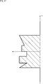
- FIG. 20 shows the reverse characteristics when the frequency characteristics of the speaker 27 and the microphone 32 measured at the time of manufacture are those shown in FIG.
- X ′ (i) ⁇ (1 / S (i) * 1 / M (i)) * X (i) ⁇ ... (2)
- the received signal Y (i) is as shown in the following equation (3).
- the frequency characteristics of the speaker 27 and the microphone 32 do not affect the received signal, so that there is a problem that a plurality of peaks appear in the delay profile described above. Can be suppressed. Therefore, since the peak corresponding to the reflected wave from the object 100 can be detected accurately, the object 100 can be accurately measured.
- the processing of the distance measuring apparatus according to the first to third embodiments described above can be executed by hardware or can be executed by software.
- a program constituting the software is installed in the computer.
- the computer includes, for example, a general-purpose personal computer capable of executing various functions by installing a computer incorporated in dedicated hardware and various programs.
- FIG. 21 is a block diagram showing an example of the hardware configuration of a computer that executes the above-described series of processes by a program.
- a CPU Central Processing Unit
- ROM Read Only Memory
- RAM Random Access Memory
- An input / output interface 205 is further connected to the bus 204.
- An input unit 206, an output unit 207, a storage unit 208, a communication unit 209, and a drive 210 are connected to the input / output interface 205.
- the input unit 206 includes a keyboard, a mouse, a microphone, and the like.
- the output unit 207 includes a display, a speaker, and the like.
- the storage unit 208 includes a hard disk, a nonvolatile memory, and the like.
- the communication unit 209 includes a network interface and the like.
- the drive 210 drives a removable medium 211 such as a magnetic disk, an optical disk, a magneto-optical disk, or a semiconductor memory.
- the CPU 201 loads, for example, the program stored in the storage unit 208 to the RAM 203 via the input / output interface 205 and the bus 204 and executes the program, and the series described above. Is performed.
- the program executed by the computer (CPU 201) can be provided by being recorded in the removable medium 211 as a package medium or the like, for example.
- the program can be provided via a wired or wireless transmission medium such as a local area network, the Internet, or digital satellite broadcasting.
- the program can be installed in the storage unit 208 via the input / output interface 205 by attaching the removable medium 211 to the drive 210.
- the program can be received by the communication unit 209 via a wired or wireless transmission medium and installed in the storage unit 208.
- the program can be installed in the ROM 202 or the storage unit 208 in advance.
- the program executed by the computer may be a program that is processed in time series in the order described in this specification, or in parallel or at a necessary timing such as when a call is made. It may be a program for processing.
- the technology according to the present disclosure can be applied to various products.
- the technology according to the present disclosure is realized as a device that is mounted on any type of mobile body such as an automobile, an electric vehicle, a hybrid electric vehicle, a motorcycle, a bicycle, personal mobility, an airplane, a drone, a ship, and a robot. May be.
- FIG. 22 is a block diagram illustrating a schematic configuration example of a vehicle control system that is an example of a mobile control system to which the technology according to the present disclosure can be applied.
- the vehicle control system 12000 includes a plurality of electronic control units connected via a communication network 12001.
- the vehicle control system 12000 includes a drive system control unit 12010, a body system control unit 12020, a vehicle exterior information detection unit 12030, a vehicle interior information detection unit 12040, and an integrated control unit 12050.
- a microcomputer 12051, an audio image output unit 12052, and an in-vehicle network I / F (interface) 12053 are illustrated.
- the drive system control unit 12010 controls the operation of the device related to the drive system of the vehicle according to various programs.
- the drive system control unit 12010 includes a driving force generator for generating a driving force of a vehicle such as an internal combustion engine or a driving motor, a driving force transmission mechanism for transmitting the driving force to wheels, and a steering angle of the vehicle. It functions as a control device such as a steering mechanism that adjusts and a braking device that generates a braking force of the vehicle.
- the body system control unit 12020 controls the operation of various devices mounted on the vehicle body according to various programs.
- the body system control unit 12020 functions as a keyless entry system, a smart key system, a power window device, or a control device for various lamps such as a headlamp, a back lamp, a brake lamp, a blinker, or a fog lamp.
- the body control unit 12020 can be input with radio waves transmitted from a portable device that substitutes for a key or signals from various switches.
- the body system control unit 12020 receives input of these radio waves or signals, and controls a door lock device, a power window device, a lamp, and the like of the vehicle.
- the vehicle outside information detection unit 12030 detects information outside the vehicle on which the vehicle control system 12000 is mounted.
- the imaging unit 12031 is connected to the vehicle exterior information detection unit 12030.
- the vehicle exterior information detection unit 12030 causes the imaging unit 12031 to capture an image outside the vehicle and receives the captured image.
- the vehicle outside information detection unit 12030 may perform an object detection process or a distance detection process such as a person, a car, an obstacle, a sign, or a character on a road surface based on the received image.
- the imaging unit 12031 is an optical sensor that receives light and outputs an electrical signal corresponding to the amount of received light.
- the imaging unit 12031 can output an electrical signal as an image, or can output it as distance measurement information. Further, the light received by the imaging unit 12031 may be visible light or invisible light such as infrared rays.
- the vehicle interior information detection unit 12040 detects vehicle interior information.
- a driver state detection unit 12041 that detects a driver's state is connected to the in-vehicle information detection unit 12040.
- the driver state detection unit 12041 includes, for example, a camera that images the driver, and the vehicle interior information detection unit 12040 determines the degree of fatigue or concentration of the driver based on the detection information input from the driver state detection unit 12041. It may be calculated or it may be determined whether the driver is asleep.
- the microcomputer 12051 calculates a control target value of the driving force generator, the steering mechanism, or the braking device based on the information inside / outside the vehicle acquired by the vehicle outside information detection unit 12030 or the vehicle interior information detection unit 12040, and the drive system control unit A control command can be output to 12010.
- the microcomputer 12051 realizes an ADAS (Advanced Driver Assistance System) function including vehicle collision avoidance or impact mitigation, following traveling based on inter-vehicle distance, vehicle speed maintaining traveling, vehicle collision warning, or vehicle lane departure warning, etc. It is possible to perform cooperative control for the purpose.
- ADAS Advanced Driver Assistance System
- the microcomputer 12051 controls the driving force generator, the steering mechanism, the braking device, and the like based on the information around the vehicle acquired by the vehicle exterior information detection unit 12030 or the vehicle interior information detection unit 12040. It is possible to perform cooperative control for the purpose of automatic driving that autonomously travels without depending on the operation.
- the microcomputer 12051 can output a control command to the body system control unit 12020 based on information outside the vehicle acquired by the vehicle outside information detection unit 12030.
- the microcomputer 12051 controls the headlamp according to the position of the preceding vehicle or the oncoming vehicle detected by the outside information detection unit 12030, and performs cooperative control for the purpose of anti-glare, such as switching from a high beam to a low beam. It can be carried out.
- the sound image output unit 12052 transmits an output signal of at least one of sound and image to an output device capable of visually or audibly notifying information to a vehicle occupant or the outside of the vehicle.
- an audio speaker 12061, a display unit 12062, and an instrument panel 12063 are illustrated as output devices.
- the display unit 12062 may include at least one of an on-board display and a head-up display, for example.
- FIG. 23 is a diagram illustrating an example of an installation position of the imaging unit 12031.
- the vehicle 12100 includes imaging units 12101, 12102, 12103, 12104, and 12105 as the imaging unit 12031.
- the imaging units 12101, 12102, 12103, 12104, and 12105 are provided, for example, at positions such as a front nose, a side mirror, a rear bumper, a back door, and an upper part of a windshield in the vehicle interior of the vehicle 12100.
- the imaging unit 12101 provided in the front nose and the imaging unit 12105 provided in the upper part of the windshield in the vehicle interior mainly acquire an image in front of the vehicle 12100.
- the imaging units 12102 and 12103 provided in the side mirror mainly acquire an image of the side of the vehicle 12100.
- the imaging unit 12104 provided in the rear bumper or the back door mainly acquires an image behind the vehicle 12100.
- the forward images acquired by the imaging units 12101 and 12105 are mainly used for detecting a preceding vehicle or a pedestrian, an obstacle, a traffic light, a traffic sign, a lane, or the like.
- FIG. 23 shows an example of the shooting range of the imaging units 12101 to 12104.
- the imaging range 12111 indicates the imaging range of the imaging unit 12101 provided in the front nose
- the imaging ranges 12112 and 12113 indicate the imaging ranges of the imaging units 12102 and 12103 provided in the side mirrors, respectively
- the imaging range 12114 The imaging range of the imaging part 12104 provided in the rear bumper or the back door is shown. For example, by superimposing the image data captured by the imaging units 12101 to 12104, an overhead image when the vehicle 12100 is viewed from above is obtained.
- At least one of the imaging units 12101 to 12104 may have a function of acquiring distance information.
- at least one of the imaging units 12101 to 12104 may be a stereo camera including a plurality of imaging elements, or may be an imaging element having pixels for phase difference detection.
- the microcomputer 12051 based on the distance information obtained from the imaging units 12101 to 12104, the distance to each three-dimensional object in the imaging range 12111 to 12114 and the temporal change in this distance (relative speed with respect to the vehicle 12100).
- a predetermined speed for example, 0 km / h or more
- the microcomputer 12051 can set an inter-vehicle distance to be secured in advance before the preceding vehicle, and can perform automatic brake control (including follow-up stop control), automatic acceleration control (including follow-up start control), and the like.
- automatic brake control including follow-up stop control
- automatic acceleration control including follow-up start control
- cooperative control for the purpose of autonomous driving or the like autonomously traveling without depending on the operation of the driver can be performed.
- the microcomputer 12051 converts the three-dimensional object data related to the three-dimensional object to other three-dimensional objects such as a two-wheeled vehicle, a normal vehicle, a large vehicle, a pedestrian, and a utility pole based on the distance information obtained from the imaging units 12101 to 12104. It can be classified and extracted and used for automatic avoidance of obstacles.
- the microcomputer 12051 identifies obstacles around the vehicle 12100 as obstacles that are visible to the driver of the vehicle 12100 and obstacles that are difficult to see.
- the microcomputer 12051 determines the collision risk indicating the risk of collision with each obstacle, and when the collision risk is equal to or higher than the set value and there is a possibility of collision, the microcomputer 12051 is connected via the audio speaker 12061 or the display unit 12062. By outputting an alarm to the driver and performing forced deceleration or avoidance steering via the drive system control unit 12010, driving assistance for collision avoidance can be performed.
- At least one of the imaging units 12101 to 12104 may be an infrared camera that detects infrared rays.
- the microcomputer 12051 can recognize a pedestrian by determining whether a pedestrian is present in the captured images of the imaging units 12101 to 12104. Such pedestrian recognition is, for example, whether or not the user is a pedestrian by performing a pattern matching process on a sequence of feature points indicating the outline of an object and a procedure for extracting feature points in the captured images of the imaging units 12101 to 12104 as infrared cameras. It is carried out by the procedure for determining.
- the audio image output unit 12052 When the microcomputer 12051 determines that there is a pedestrian in the captured images of the imaging units 12101 to 12104 and recognizes the pedestrian, the audio image output unit 12052 has a rectangular contour line for emphasizing the recognized pedestrian.
- the display unit 12062 is controlled so as to be superimposed and displayed.
- voice image output part 12052 may control the display part 12062 so that the icon etc. which show a pedestrian may be displayed on a desired position.
- the technology according to the present disclosure can be applied to, for example, the imaging unit 12031 that performs distance measurement instead of the imaging unit 12031 that performs distance measurement.
- the present technology can also have the following configurations.
- An OFDM modulation unit that generates an OFDM signal by performing OFDM modulation on the transmission signal;
- An output unit for outputting the OFDM signal as an ultrasonic wave carrier;
- a sound collection unit that collects ultrasonic waves as reflected waves in the output ultrasonic target as reception signals;
- a demodulator that generates a demodulated signal by demodulating the received signal;
- a distance measuring apparatus comprising: a calculation unit that calculates a delay time of the ultrasonic wave from the delay profile and calculates a distance to the object based on the delay time.
- a division unit that generates a transfer function by dividing the demodulated signal by the OFDM signal; The ranging device according to (1), wherein the calculation unit calculates the delay profile by performing inverse Fourier transform on the transfer function.
- a quadrature modulation unit that performs quadrature modulation of the OFDM signal before being conveyed by the ultrasonic wave, The ranging apparatus according to (1) or (2), wherein the demodulation unit performs orthogonal demodulation corresponding to the orthogonal modulation on the received signal, and generates the demodulated signal by performing Fourier transform.
- the OFDM modulation unit provides a guard interval for the OFDM signal.
- the ranging device (4), wherein the OFDM modulation unit provides the guard interval having the same length as the OFDM effective symbol length.
- the OFDM modulation unit sets an FFT size, which is a parameter in OFDM modulation, to a power of 2, and sets the number of carriers to 1 ⁇ 2 of the FFT size.
- a replica signal generation unit that generates a replica signal corresponding to the crosstalk component;
- the distance measuring apparatus according to any one of (1) to (6), further including a subtracting unit that subtracts the replica signal from the received signal.
- a crosstalk measurement unit that measures crosstalk information is further provided.
- the ranging apparatus wherein the replica signal generation unit generates the replica signal based on the crosstalk information.
- the crosstalk measuring unit measures at least one of a delay time corresponding to crosstalk, an attenuation of the amplitude of an OFDM signal, or a phase rotation as the crosstalk information. .
- the distance measuring device according to (8) or (9), wherein the crosstalk measuring unit periodically updates the crosstalk information.
- the range finder according to (8) or (9), wherein the crosstalk measurement unit updates the crosstalk information when a peak corresponding to crosstalk appears in the delay profile.
- An OFDM modulation step for generating an OFDM signal by performing OFDM modulation on the transmission signal;
- a distance measuring method comprising: calculating a delay time of the ultrasonic wave from the delay profile and calculating a distance to the object based on the delay time.
- An OFDM modulation unit that generates an OFDM signal by performing OFDM modulation on the transmission signal;
- An output unit for outputting the OFDM signal as an ultrasonic wave carrier;
- a sound collection unit that collects ultrasonic waves as reflected waves in the output ultrasonic target as reception signals;
- a demodulator that generates a demodulated signal by demodulating the received signal;
- a calculation unit for calculating a delay profile based on the own signal obtained in the process of generating the OFDM signal and the demodulated signal;
- a program for obtaining a delay time of the ultrasonic wave from the delay profile and functioning as a calculation unit that calculates a distance to the object based on the delay time.
Landscapes
- Engineering & Computer Science (AREA)
- Computer Networks & Wireless Communication (AREA)
- Radar, Positioning & Navigation (AREA)
- Remote Sensing (AREA)
- Physics & Mathematics (AREA)
- Signal Processing (AREA)
- General Physics & Mathematics (AREA)
- Acoustics & Sound (AREA)
- Electromagnetism (AREA)
- Measurement Of Velocity Or Position Using Acoustic Or Ultrasonic Waves (AREA)
Abstract
本技術は、対象物を正確に測距することができるようにする測距装置、測距方法、およびプログラムに関する。 本技術の一側面である測距装置は、送信信号にOFDM変調を行うことによりOFDM信号を生成するOFDM変調部と、前記OFDM信号を超音波を搬送波として出力する出力部と、前記出力部から出力された前記超音波の対象物における反射波としての超音波を受信信号として集音部と、前記受信信号を復調することにより復調信号を生成する復調部と、前記OFDM信号の生成過程で得られる自信号と前記復調信号とに基づいて遅延プロファイルを算出する算出部と、前記遅延プロファイルから前記超音波の遅延時間を求め、前記遅延時間に基づいて前記対象物までの距離を演算する演算部とを備える。本技術は、例えば、自動車に適用することができる。
Description
本技術は、測距装置、測距方法、およびプログラムに関し、特に、超音波を対象物に照射して、その反射波に基づいて対象物までの距離を測定する測距装置、測距方法、およびプログラムに関する。
従来、超音波を用いた測距を行う測距装置として、パルスエコー方式を採用したものが存在する(例えば、特許文献1参照)。
ここで、超音波とは、正常な聴力を持つ人に聴感覚を生じないほど周波数(振動数)が高い音波(弾性波)を指す。
図1は、パルスエコー方式を採用した測距装置の従来の構成の一例を示すブロック図である。
該測距装置は、送信部1、受信部2、タイマ11、インタフェース部9、および制御部10から構成される。
送信部1は、発振部3、駆動部4、および超音波スピーカ5(以下、スピーカ5と略称する)を有する。受信部2は、超音波マイクロフォン6(以下、マイク6と略称する)、増幅検波部7、およびシュミットトリガ部8を有する。
該測距装置においては、送信部1のスピーカ5から超音波が、距離を測定したい対象物に向けて出力され、その反射波が受信部2のマイク6によって集音される。
マイク6で集音された反射波に対応する電気信号は、増幅検波部で増幅、検波され、シュミットトリガ部8で、その振幅が所定の閾値と比較され、その比較結果であるシュミットトリガがタイマ11に供給される。
タイマ11は、超音波が送信されたタイミングと反射が集音されたタイミングを計測し、それぞれを、インタフェース部9を介して制御部10に出力する。制御部10では、両タイミングの時間差分tdを算出し、時間差分tdを次式(1)に適用して対象物までの距離Lを算出する。ここで、vは超音波の速度である。
L=v×td/2・・・(1)
L=v×td/2・・・(1)
図2は、図1の測距装置における超音波の出力、集音等のタイミングを示している。
例えば、同図Aに示される矩形波の測定要求パルスが制御部10からインタフェース部9を介して発振部3に供給されると、発振部3は、同図Bに示すように、測定要求パルスに対応する超音波信号を駆動部4に出力する。駆動部4は、この超音波信号に対応してスピーカ5を振動させることにより、スピーカ5から超音波を出力させる。しかしながら、スピーカ5から出力される超音波は、その特性や環境音等に起因して、同図Cに示すようにその波形は歪み、対象物からの反射波の波形についてはさらに同図Dに示すように歪んだものとなる。
シュミットトリガ部8では、同図Dに示された反射波の振幅と、同図Eに示すような所定の検出閾値と比較し、比較結果を表す同図Fに示すようなシュミットトリガ出力をタイマ11に供給する。タイマ11は、超音波が送信されたタイミングを制御部10に通知するとともに、同図Fに示されたシュミットトリガ出力の立ち上がりのタイミングを、超音波が集音されたタイミングとして検出して制御部10に通知する。制御部10では、両タイミングの差を時間差分tdとして算出し、時間差分tdを用いて対象物までの距離Lを算出する。
上述したように、シュミットトリガ出力は、シュミットトリガ回路8における検出閾値に依存しているので、集音した反射波の振幅が減衰していたり、検出閾値の設定が適切ではなかったりした場合、シュミットトリガ出力の立ち上がりのタイミング、すなわち、超音波が集音されたタイミングを正確に検出することができない。よって、その場合、時間差分tdに誤差が生じているので、それに基づいて算出される距離Lの精度も低下してしまうことになる。
本技術は、このような状況に鑑みて提案されたものであり、超音波の送受信タイミングの時間差であるtdを高い精度で検出することにより、対象物を正確に測距できるようにするものである。
本技術の一側面である測距装置は、送信信号にOFDM変調を行うことによりOFDM信号を生成するOFDM変調部と、前記OFDM信号を超音波を搬送波として出力する出力部と、出力された前記超音波の対象物における反射波としての超音波を受信信号として集音する集音部と、前記受信信号を復調することにより復調信号を生成する復調部と、前記OFDM信号の生成過程で得られる自信号と前記復調信号とに基づいて遅延プロファイルを算出する算出部と、前記遅延プロファイルから前記超音波の遅延時間を求め、前記遅延時間に基づいて前記対象物までの距離を演算する演算部とを備える。
本技術の一側面である測距装置は、前記復調信号を前記OFDM信号で除算することにより伝達関数を生成する除算部をさらに備えることができ、前記算出部は、前記伝達関数に逆フーリエ変換を行うことにより前記遅延プロファイルを算出することができる。
本技術の一側面である測距装置は、前記超音波によって搬送される前の前記OFDM信号の直交変調を行う直交変調部をさらに備えることができ、前記復調部は、前記受信信号に前記直交変調に対応する直交復調を行い、フーリエ変換を行うことにより前記復調信号を生成することができる。
前記OFDM変調部は、前記OFDM信号にガードインターバルを設けることができる。
前記OFDM変調部は、OFDM有効シンボル長と同じ長さを有する前記ガードインターバルを設けることができる。
前記OFDM変調部は、OFDM変調におけるパラメータであるFFTサイズを2の累乗とし、搬送波数を前記FFTサイズの1/2とすることができる。
本技術の一側面である測距装置は、クロストーク成分に対応するレプリカ信号を生成するレプリカ信号生成部と、前記受信信号から前記レプリカ信号を減算する減算部とさらに備えることができる。
本技術の一側面である測距装置は、クロストーク情報を測定するクロストーク測定部をさらに備えることができ、前記レプリカ信号生成部は、前記クロストーク情報に基づいて前記レプリカ信号を生成することができる。
クロストーク測定部は、前記クロストーク情報として、クロストークに対応する遅延時間、OFDM信号の振幅の減衰、または位相の回転のうちの少なくとも一つを測定することができる。
前記クロストーク測定部は、前記クロストーク情報を定期的に更新することができる。
前記クロストーク測定部は、前記遅延プロファイルにクロストークに対応するピークが出現した場合、前記クロストーク情報を更新することができる。
本技術の一側面である測距装置は、前記出力部としての超音波スピーカと、前記集音部としての超音波マイクロフォンの周波数特性に起因する前記受信信号の歪みを補正するキャンセル部をさらに備えることができる。
前記キャンセル部は、前記OFDM変調部に含まれているようにすることができる。
前記キャンセル部は、超音波スピーカと前記超音波マイクロフォンの周波数特性に対する逆特性を前記OFDM信号の生成過程において乗算することができる。
本技術の一側面である測距方法は、測距装置による測距方法において、前記測距装置による、送信信号にOFDM変調を行うことによりOFDM信号を生成するOFDM変調ステップと、前記OFDM信号を超音波を搬送波として出力する出力ステップと、出力された前記超音波の対象物における反射波としての超音波を受信信号として集音する集音ステップと、前記受信信号を復調することにより復調信号を生成する復調ステップと、前記OFDM信号の生成過程で得られる自信号と前記復調信号とに基づいて遅延プロファイルを算出する算出ステップと、前記遅延プロファイルから前記超音波の遅延時間を求め、前記遅延時間に基づいて前記対象物までの距離を演算する演算ステップとを含む。
本技術の一側面であるプログラムは、コンピュータを、送信信号にOFDM変調を行うことによりOFDM信号を生成するOFDM変調部と、前記OFDM信号を超音波を搬送波として出力する出力部と、出力された前記超音波の対象物における反射波としての超音波を受信信号として集音する集音部と、前記受信信号を復調することにより復調信号を生成する復調部と、前記OFDM信号の生成過程で得られる自信号と前記復調信号とに基づいて遅延プロファイルを算出する算出部と、前記遅延プロファイルから前記超音波の遅延時間を求め、前記遅延時間に基づいて前記対象物までの距離を演算する演算部として機能させる。
本技術の一側面においては、送信信号にOFDM変調を行うことによりOFDM信号が生成され、前記OFDM信号が超音波を搬送波として出力され、出力された前記超音波の対象物における反射波としての超音波が受信信号として集音され、前記受信信号を復調することにより復調信号が生成され、前記OFDM信号の生成過程で得られる自信号と前記復調信号とに基づいて遅延プロファイルが算出され、前記遅延プロファイルから前記超音波の遅延時間が求められて、前記遅延時間に基づいて前記対象物までの距離が演算される。
本技術の一側面によれば、対象物を正確に測距することが可能となる。
以下、本技術を実施するための最良の形態(以下、実施の形態と称する)について、図面を参照しながら詳細に説明する。
以下、本開示を実施するための最良の形態(以下、実施の形態と称する)について図面を参照しながら説明するが、その前に、本技術の概要について説明する。
<本技術の測距装置の概要>
本技術を適用した測距装置は、対象物までの距離を測定するに際して超音波を出力し、その反射波を集音して、超音波の送受信に要した時間を求める点において従来のパルスエコー方式と同じである。ただし、OFDM(Orthogonal Frequency Division Multiplexing、直交周波数分割多重方式)変調された信号(以下、OFDM信号と称する)の搬送波としての超音波を送受信することにより、演算によって超音波の送受信に要した時間を求める点が異なる。これにより、従来のようにシュミットトリガ出力を求める場合に比較して、超音波の送受信に要した時間を正確に求めることができ、高い精度で対象物までの距離を演算することが可能となる。
本技術を適用した測距装置は、対象物までの距離を測定するに際して超音波を出力し、その反射波を集音して、超音波の送受信に要した時間を求める点において従来のパルスエコー方式と同じである。ただし、OFDM(Orthogonal Frequency Division Multiplexing、直交周波数分割多重方式)変調された信号(以下、OFDM信号と称する)の搬送波としての超音波を送受信することにより、演算によって超音波の送受信に要した時間を求める点が異なる。これにより、従来のようにシュミットトリガ出力を求める場合に比較して、超音波の送受信に要した時間を正確に求めることができ、高い精度で対象物までの距離を演算することが可能となる。
<本技術の第1の実施の形態である測距装置の構成について>
図3は、本技術の第1の実施の形態である測距装置の構成例を示すブロック図である。
図3は、本技術の第1の実施の形態である測距装置の構成例を示すブロック図である。
該第1の実施の形態は、超音波を対象物100に向けて出力する送信部21と、その反射波(受信信号)を集音して送受信タイミングの時間差を求める受信部31と、送受信タイミングの時間差に基づいて対象物100までの距離を演算する演算部41から構成される。なお、送信部21と受信部31は、隣接して配置するものとする。
送信部21は、OFDM変調部22、直交変調部25、ローカルオシレータ26、および超音波スピーカ27(以下、スピーカ27と略称する)から構成される。
OFDM変調部22は、デジタル変調部23および逆フーリエ変換部24を有する。デジタル変調部23は、例えば、矩形波等の送信信号に所定のデジタル変調を行い、その結果得られる位相と振幅を逆フーリエ変換部24に出力する。なお、所定のデジタル変調の結果得られる位相と振幅は、自信号として受信部31の除算部35にも通知される。逆フーリエ変換部24は、デジタル変調部23の出力に対して逆フーリエ変換を行うことにより、送信信号に対応するOFDM信号を生成し、さらにガードインターバルを追加して直交変調部25に出力する。
図4は、OFDM信号にガードインターバルを追加して送受信した場合のタイミングチャートを示している。なお、同図Aは送信タイミング、同図Bは受信タイミングを示している。図示されるように、OFDM信号のシンボル間にガードインターバルを追加することにより、送受信される信号は冗長となるものの、後述するマルチパスの影響を抑止することが可能となる。
図5は、OFDM変調部22におけるOFDM変調に関するパラメータの例を示している。
具体的には、OFDM帯域幅、最大検出距離、検出精度、搬送波間隔、搬送波数、FFTサイズ、サンプリング周波数、OFDMシンボル長、OFDM有効シンボル長、およびガードインターバル長を示している。
なお、同図においては、OFDM帯域幅を8.192kHzまたは16.384kHzに設定した場合を示しているが、OFDM帯域幅はこれら2種類に限定されるものではない。
列挙したパラメータのうち、最大検出距離、搬送波間隔、OFDMシンボル長、およびOFDM有効シンボル長については、OFDM帯域幅に拘わらず共通であり、その他については、OFDM帯域幅に応じて変更される。
OFDM変調部22におけるパラメータの特徴としては、FFT(フーリエ変換)サイズを2の累乗に設定し、搬送波数をその1/2に設定している点を挙げることができる。例えば、OFDM帯域幅が8.192kHzである場合のFFTサイズは1024(=210)、そのときの搬送波数は512、OFDM帯域幅が16.384kHzである場合のFFTサイズは20484(=211)、そのときの搬送波数は1024としている。このように、FFTサイズを2の累乗とし、搬送波数をその1/2とすることで、OFDM変調、復調時の演算負担を軽減することができる。特に、フーリエ変換、逆フーリエ変換の演算量を減らすことができる。
さらに、ガードインターバル長を、OFDM有効シンボル長と同じ長さにしている点を挙げることができる。これにより、より効果的にシンボル間の干渉を防止することができるとともに、遅延プロファイルから取得できる遅延時間を最長まで長くすることができ、測定可能な対象物100までの距離を表す最大検出距離を最長に伸ばすことができる。
図3に戻る。直交変調部25は、逆フーリエ変換部24から供給される、ガードインターバルが追加されたOFDM信号を設けて直交変調を行い、搬送波周波数f0を中心とした超音波としてスピーカ27から出力させる。ローカルオシレータ26は、直交変調部25に対して搬送波周波数f0のクロック信号を供給する。なお、搬送波周波数f0については、ローカルオシレータ26が受信部31の直交復調部33に予め通知しているものとする。
受信部31は、超音波マイクロフォン32(以下、マイク32と略称する)、直交復調部33、フーリエ変換部34、除算部35、および逆フーリエ変換部36から構成される。
マイク32は、スピーカ27から出力されて対象物100で反射された超音波を集音し、それに対応する受信信号を直交復調部33に出力する。
直交復調部33は、マイク32から入力された受信信号に対して、送信部21の直交変調部25による直交変調に対応する直交復調を行い、その結果得られる直交復調信号をフーリエ変換部34に出力する。なお、直交復調部33は予め搬送波周波数f0に関する情報を保持しているので、搬送波再生などの処理を省略することができる。
フーリエ変換部34は、直交復調信号に対してフーリエ変換を行い、その結果を除算部35に出力する。
除算部35は、フーリエ変換部34によるフーリエ変換の結果を、送信部21のOFDM変調部22から供給されている自信号で除算することにより、反射波の伝達関数を演算して逆フーリエ変換部36に出力する。逆フーリエ変換部36は、伝達関数に逆フーリエ変換を行い、その結果得られる、OFDM信号の送受信時間に要した時間を取得できる遅延プロファイルを演算部41に出力する。
なお、反射波の伝達関数から遅延プロファイルを求める原理については、確立された既存技術として、例えば、”ディジタル信号処理入門”、城戸健一著、丸善株式会社等に記載されている。
演算部41は、遅延プロファイルから時間差分tdを求めて式(1)に適用し、対象物100までの距離を演算する。
図6は、伝達関数に逆フーリエ変換を行うことによって得られる遅延プロファイルの一例を示している。
同図に示されるように、遅延プロファイルには、OFDM信号の送受信時間に要した時間に最大のピークが出現する。よって、演算部41では、遅延プロファイルにおけるピークを検出することによってOFDM信号の送受信時間に要した時間を求めることができる。
<本技術の第1の実施の形態である測距装置の動作について>
次に、本技術の第1の実施の形態である測距装置の動作について説明する。
次に、本技術の第1の実施の形態である測距装置の動作について説明する。
図7は、送信部21が行う送信処理を説明するフローチャートである。
対象物100まの距離を測定するに際しては、ステップS1において、送信部21では、OFDM変調部22のデジタル変調部23が、矩形波等の送信信号に所定のデジタル変調を行い、その結果得られる位相と振幅を逆フーリエ変換部24に出力する。ステップS2において、逆フーリエ変換部24は、デジタル変調部23の出力に対して逆フーリエ変換を行うことにより、送信信号に対応するOFDM信号を生成し、さらにガードインターバルを追加して直交変調部25に出力する。
ステップS3において、直交変調部25は、逆フーリエ変換部24から供給されたガードインターバルが設けられているOFDM信号に対して直交変調を行い、搬送波周波数f0を中心とした超音波としてスピーカ27から出力させる。該超音波は対象物100で反射される。
ステップS4においては、受信部31では、対象物100で反射された超音波の反射波を集音し、それに対応する受信信号を直交復調部33に出力する。
ステップS5において、マイク32から入力された受信信号に対して、送信部21の直交変調部25による直交変調に対応する直交復調を行い、その結果得られる直交復調信号をフーリエ変換部34に出力する。ステップS6において、フーリエ変換部34は、直交復調信号に対してフーリエ変換を行い、その結果を除算部35に出力する。
ステップS7において、除算部35は、フーリエ変換部34によるフーリエ変換の結果を、送信部21のOFDM変調部22から供給されている自信号情報で除算することにより、反射波の伝達関数を算出して逆フーリエ変換部36に出力する。
ステップS8において、逆フーリエ変換部36は、除算部35から入力された伝達関数に逆フーリエ変換を行い、その結果得られる遅延プロファイルを演算部41に出力する。
ステップS9において、演算部41は、遅延プロファイルから時間差分tdを検出し、時間差分tdを式(1)に適用して対象物100までの距離を演算する。
以上で、本技術の第1の実施の形態である測距装置の動作説明を終了する。以上説明したように、本技術の第1の実施の形態である測距装置では、パルスエコー方式のようにシュミットトリガ出力を用いるのではなく、演算により伝達関数を求め、伝達関数から遅延プロファイルを求めて時間差分tdを検出している。よって、パルスエコー方式に比較してより正確に時間差分tdを求めることができ、高い精度で対象物100を測距することができる。また、OFDM信号のガードインターバルを設けているので、マルチパスによる影響を軽減することができる。
ここで、マルチパスが生じた場合の遅延プロファイルについて説明する。
図8は、本技術の第1の実施の形態である測距装置が出力する超音波にマルチパスが生じている場合を示している。すなわち、スピーカ27から出力される超音波の経路としては、実線で示される経路のように、スピーカ27から直接、対象物100に達し、その反射波が直接マイク32に集音されることが望ましい。しかしながら、状況によっては、破線や一点鎖線で示される経路のように、スピーカ27から対象物100以外の物体で反射したり、対象物100からの反射波がさらに他の物体で反射したりしてマイク32に集音されることがある。
このような場合、破線や一点鎖線で示された経路は、実線で示された経路よりも長くなるので、実線で示された経路の反射波よりもマイク32で集音されるタイミングが遅くなる。
図9は、図8に示されように、マルチパスが生じている場合の超音波の出力、集音のタイミングを示している。同図Aに示されるタイミングで出力された超音波は、実線で示された経路で反射された場合、同図Bに示されるように時間差分td1を要して集音される。また、破線で示された経路で反射された場合、同図Cに示されるように、時間差分td2を要して集音される。一点鎖線で示された経路で反射された場合、同図Dに示されるように、時間差分td3を要して集音される。
図10は、図9に示された場合に対応する遅延プロファイルを示している。本技術の第1の実施の形態である測距装置では、遅延プロファイルに時間差分に対応するピークとして、時間差分tdが出現する。すなわち、遅延プロファイルには、時間差分td1,td2に対応するピークが出現する。したがって、遅延プロファイルに基づいて、時間差分tdを検出すれば、マルチパスを分離して検出できることが分かる。
なお、図10に示すように、遅延プロファイルに複数のピークが出現している場合には、例えば、今回得られた遅延プロファイルと、直前に得られた遅延プロファイルとを比較し、比較結果に基づき、所定の規則に従って、いずれかのピークを選択し、対象物100までの距離Lを算出するために用いる時間差分tdを検出すればよい。
図11は、時間差分td3がガードインターバル長を超えた反射波の例を示している。同図のように、ガードインターバル長を超えて集音された反射波については、シンボル間干渉が発生した状況となり、他の反射波に対して外乱となるとともに、正確に遅延時間を測定できない。
<本技術の第2の実施の形態である測距装置について>
ところで、上述したように、送信部21と受信部31を隣接して配置し、さらにこれらの小型化を推進した場合、送信部21から出力された超音波が、受信部31によって直接集音されてしまうクロストークが発生し得る。
ところで、上述したように、送信部21と受信部31を隣接して配置し、さらにこれらの小型化を推進した場合、送信部21から出力された超音波が、受信部31によって直接集音されてしまうクロストークが発生し得る。
図12は、クロストークが生じている場合の超音波の出力、集音のタイミングを示している。同図Aは、超音波の出力タイミング、同図Bはクロストークの集音タイミング、同図Bは対象物100からの反射波の集音タイミング示している。
同図Bに示されるように、クロストークによって直接集音される超音波(以下、クロストーク成分と称する)は距離減衰や反射による減衰が起きていないので、同図Cに示された対象物100からの反射波よりも振幅が大きなものとなる。
図13は、図12に示されたクロストークが生じている場合に対応する遅延プロファイルを示している。
同図に示されるように、クロストークが生じている場合の遅延プロファイルには、クロストークに対応する極短時間の時間差分td_crossが出現するとともに、対象物100からの反射波に対応する時間差分tdを表すピークが、AD変換による量子化ノイズ(noise)に埋もれてしまい正確に検出できない。よって、測距の性能が劣化してしまうことになる。
そこで、次に、クロストーク成分を除去できる測距装置について説明する。
図14は、本技術の第2の実施の形態である測距装置の構成例を示すブロック図である。該第2の実施の形態は、上述した第1の実施の形態に、クロストーク成分を除去できる機能を付加したものである。
すなわち、第2の実施の形態である測距装置は、図3に示された第1の実施の形態にクロストーク測定部61、レプリカ信号生成部62、および減算部63を追加したものである。その他の構成要素については第1の実施の形態と共通であり、同一の符号を付しているので、その説明は適宜省略する。
クロストーク測定部61は、製造時などに対象物100が存在していないか、非常に遠方に存在している状態で該測距装置を動作させることにより、逆フーリエ変換部24から出力されるOFDM信号と、受信部31の各部から得られる情報とに基づき、クロストーク情報(時間差分td_cross、OFDM信号の振幅の減衰、位相の回転)を測定し、測定結果をレプリカ信号生成部62に供給する。なお、クロストーク測定部61がクロストーク情報を測定しているときには、後述するレプリカ信号生成部62および減算部63は動作させないものとする。
レプリカ信号生成部62は、クロストーク測定部61から供給されるクロストーク情報に基づき、逆フーリエ変換部から出力されるOFDM信号に対して、時間差分td_crossの遅延、OFDM信号の振幅の減衰、位相の回転を行い、さらに、直交変調部25と同じ直交変調を行うことにより、クロストーク成分に対応するレプリカ信号を生成して減算部63に出力する。
減算部63は、マイク32の集音結果(対象物100からの反射波とクロストーク成分)に対応する受信信号からレプリカ信号を減算して直交復調部33に出力する。これにより、直交復調部33には、クロストーク成分に相当するレプリカ信号が除去された受信信号が供給されることになる。直交復調部33以降の処理は、第1の実施の形態と共通であるので、その説明は省略する。
図15は、クロストーク成分に相当するレプリカ信号が減算されている場合に対応する遅延プロファイルを示している。
同図と、図13に示されたクロストークが生じている場合に対応する遅延プロファイルとを比較すると以下のことが言える。すなわち、クロストーク成分に対応するレプリカ信号が減算されている場合の遅延プロファイルには、クロストークに対応する極短時間の時間差分td_crossが出現しない。また、振幅が大きいクロストーク成分が存在しないことにより、AD変換による量子化ノイズ(noise)が小さくなるので、対象物100からの反射波に対応する時間差分tdを表すピークを正確に検出することができる。よって、対象物100を正確に測距することができる。
なお、第2の実施の形態である測距装置に生じ得るクロストーク成分は、経年劣化などによって変化し得る。その場合、変化前、すなわち、製造時に測定されたクロストーク情報に基づいてレプリカ信号を生成していたのではクロストーク成分を正確に除去しきれない。
そこで、経年劣化に起因するクロストークにも対応できるように、対象物100を測距する場合にもクロストーク測定部61にて遅延プロファイルを監視するようにする。そして、クロストーク成分に対応する時間差分td_crossが遅延プロファイルに出現するようになった場合、改めて製造時と同様にクロストーク情報を測定するようにする。このようにすれば、経年劣化でクロストーク成分に変化が生じても、それに対応することができ、対象物100を正確に測距することができる。
なお、クロストーク測定部61にて、所定の周期でクロストーク情報を測定、更新するようにしてもよい。このようにすれば、経年劣化でクロストーク成分に変化が生じても、それに対応することができ、対象物100を正確に測距することができる。
<本技術の第3の実施の形態である測距装置について>
ところで、本実施の形態のように測距に超音波を用いる場合、超音波を出力するスピーカ27と超音波を集音するマイク32は超音波帯域の周波数特性がフラットであることが理想である。しかしながら、アナログ部品であるスピーカ27およびマイク32は、それぞれ個体固有の周波数特性を有するので、以下に説明する問題が生じ得る。
ところで、本実施の形態のように測距に超音波を用いる場合、超音波を出力するスピーカ27と超音波を集音するマイク32は超音波帯域の周波数特性がフラットであることが理想である。しかしながら、アナログ部品であるスピーカ27およびマイク32は、それぞれ個体固有の周波数特性を有するので、以下に説明する問題が生じ得る。
図16乃至図18は、スピーカ27およびマイク32の周波数特性に起因する問題を説明するための図である。
スピーカ27およびマイク32の周波数特性がフラットである場合、受信部31のフーリエ変換部34によるフーリエ変換後のスペクトルは、図16に示されるように歪みなく、平坦なものとなる。
しかしながら、実際には、スピーカ27およびマイク32の周波数特性が影響し、受信部31のフーリエ変換部34によるフーリエ変換後のスペクトルは、図17に示されるように歪みが生じたものとなる。
このように、歪みが生じたフーリエ変換結果に基づいて伝達関数を算出し、遅延プロファイルを求めると、該遅延プロファイルには、図18に示されるように、マルチパスが生じている状態と同様に複数のピークが出現してしまい、対象物100からの反射波に対応するピークを正確に検出できなくなってしまう。
そこで、次に、スピーカ27およびマイク32の周波数特性の影響を除去できる測距装置について説明する。
図19は、本技術の第3の実施の形態である測距装置の構成例を示すブロック図である。該第3の実施の形態は、上述した第1の実施の形態に、スピーカ27およびマイク32の周波数特性の影響を除去できる機能を付加したものである。
すなわち、第3の実施の形態である測距装置は、図3に示された第1の実施の形態のデジタル変調部23と逆フーリエ変換部24の間にキャンセル部81を追加したものである。その他の構成要素については第1の実施の形態と共通であり、同一の符号を付しているので、その説明は適宜省略する。
キャンセル部81は、予め保持されているスピーカ27およびマイク32の周波数特性の逆特性をデジタル変調部23の出力にかけてから逆フーリエ変換部24に出力する。なお、スピーカ27およびマイク32の周波数特性は、製造時に、図17に示されたようなフーリエ変換後の歪みが生じたスペクトルが測定されており、キャンセル部81には、その逆特性が予め保持されているものとする。
図20は、製造時に測定されたスピーカ27およびマイク32の周波数特性が図17に示されたものである場合におけるその逆特性を示している。
キャンセル部81における具体的な処理は以下のとおりである。
X(i):i番目のサブキャリアの信号
M(i):i番目のサブキャリアの位置におけるスピーカ27の周波数特性
H(i):i番目のサブキャリアの位置におけるチャネルの周波数特性
S(i):i番目のサブキャリアの位置におけるマイク32の周波数特性
N(i):i番目のサブキャリアの位置でのAWGN
Y(i):i番目のサブキャリアの受信信号
各変数を上記のように定義した場合、キャンセル部81は、次式(2)を計算することになる。
X’(i)={(1/S(i)*1/M(i))*X(i)}
・・・(2)
X(i):i番目のサブキャリアの信号
M(i):i番目のサブキャリアの位置におけるスピーカ27の周波数特性
H(i):i番目のサブキャリアの位置におけるチャネルの周波数特性
S(i):i番目のサブキャリアの位置におけるマイク32の周波数特性
N(i):i番目のサブキャリアの位置でのAWGN
Y(i):i番目のサブキャリアの受信信号
各変数を上記のように定義した場合、キャンセル部81は、次式(2)を計算することになる。
X’(i)={(1/S(i)*1/M(i))*X(i)}
・・・(2)
この場合、受信信号Y(i)は次式(3)に示されるとおりとなる。
Y(i)=S(i)*H(i)*M(i)*X’(i)+N(i)
=S(i)*H(i)*M(i)*{(1/S(i)*1/M(i))*X(i)}+N(i)
=S(i)*(1/S(i))*H(i)*M(i)*(1/M(i))*X(i)+N(i)
=H(i)*X(i)+N(i)
・・・(3)
Y(i)=S(i)*H(i)*M(i)*X’(i)+N(i)
=S(i)*H(i)*M(i)*{(1/S(i)*1/M(i))*X(i)}+N(i)
=S(i)*(1/S(i))*H(i)*M(i)*(1/M(i))*X(i)+N(i)
=H(i)*X(i)+N(i)
・・・(3)
式(3)から明らかなように、受信信号Y(i)からはスピーカ27とマイク32の周波数特性が除去でできていることがわかる。
したがって、本技術の第3の形態の場合、受信信号にスピーカ27とマイク32の周波数特性は影響しないことになるので、上述した遅延プロファイルに複数のピークが出現してしまうような問題の発生を抑止できる。よって、対象物100からの反射波に対応するピークを正確に検出できるので、対象物100を正確に測距することが可能となる。
なお、上述した第1乃至第3の実施の形態は、適宜組み合わせることも可能である。
ところで、上述した第1乃至第3の実施の形態である測距装置の処理は、ハードウェアにより実行することもできるし、ソフトウェアにより実行することもできる。一連の処理をソフトウェアにより実行する場合には、そのソフトウェアを構成するプログラムが、コンピュータにインストールされる。ここで、コンピュータには、専用のハードウェアに組み込まれているコンピュータや、各種のプログラムをインストールすることで、各種の機能を実行することが可能な、例えば汎用のパーソナルコンピュータなどが含まれる。
図21は、上述した一連の処理をプログラムにより実行するコンピュータのハードウェアの構成例を示すブロック図である。
コンピュータにおいて、CPU(Central Processing Unit)201,ROM(Read Only Memory)202,RAM(Random Access Memory)203は、バス204により相互に接続されている。
バス204には、さらに、入出力インタフェース205が接続されている。入出力インタフェース205には、入力部206、出力部207、記憶部208、通信部209、およびドライブ210が接続されている。
入力部206は、キーボード、マウス、マイクロフォンなどよりなる。出力部207は、ディスプレイ、スピーカなどよりなる。記憶部208は、ハードディスクや不揮発性のメモリなどよりなる。通信部209は、ネットワークインタフェースなどよりなる。ドライブ210は、磁気ディスク、光ディスク、光磁気ディスク、又は半導体メモリなどのリムーバブルメディア211を駆動する。
以上のように構成されるコンピュータでは、CPU201が、例えば、記憶部208に記憶されているプログラムを、入出力インタフェース205およびバス204を介して、RAM203にロードして実行することにより、上述した一連の処理が行われる。
コンピュータ(CPU201)が実行するプログラムは、例えば、パッケージメディア等としてのリムーバブルメディア211に記録して提供することができる。また、プログラムは、ローカルエリアネットワーク、インターネット、デジタル衛星放送といった、有線または無線の伝送媒体を介して提供することができる。
コンピュータでは、プログラムは、リムーバブルメディア211をドライブ210に装着することにより、入出力インタフェース205を介して、記憶部208にインストールすることができる。また、プログラムは、有線または無線の伝送媒体を介して、通信部209で受信し、記憶部208にインストールすることができる。その他、プログラムは、ROM202や記憶部208に、あらかじめインストールしておくことができる。
なお、コンピュータが実行するプログラムは、本明細書で説明する順序に沿って時系列に処理が行われるプログラムであってもよいし、並列に、あるいは呼び出しが行われたとき等の必要なタイミングで処理が行われるプログラムであってもよい。
<移動体への応用例>
本開示に係る技術(本技術)は、様々な製品へ応用することができる。例えば、本開示に係る技術は、自動車、電気自動車、ハイブリッド電気自動車、自動二輪車、自転車、パーソナルモビリティ、飛行機、ドローン、船舶、ロボット等のいずれかの種類の移動体に搭載される装置として実現されてもよい。
本開示に係る技術(本技術)は、様々な製品へ応用することができる。例えば、本開示に係る技術は、自動車、電気自動車、ハイブリッド電気自動車、自動二輪車、自転車、パーソナルモビリティ、飛行機、ドローン、船舶、ロボット等のいずれかの種類の移動体に搭載される装置として実現されてもよい。
図22は、本開示に係る技術が適用され得る移動体制御システムの一例である車両制御システムの概略的な構成例を示すブロック図である。
車両制御システム12000は、通信ネットワーク12001を介して接続された複数の電子制御ユニットを備える。図22に示した例では、車両制御システム12000は、駆動系制御ユニット12010、ボディ系制御ユニット12020、車外情報検出ユニット12030、車内情報検出ユニット12040、及び統合制御ユニット12050を備える。また、統合制御ユニット12050の機能構成として、マイクロコンピュータ12051、音声画像出力部12052、及び車載ネットワークI/F(interface)12053が図示されている。
駆動系制御ユニット12010は、各種プログラムにしたがって車両の駆動系に関連する装置の動作を制御する。例えば、駆動系制御ユニット12010は、内燃機関又は駆動用モータ等の車両の駆動力を発生させるための駆動力発生装置、駆動力を車輪に伝達するための駆動力伝達機構、車両の舵角を調節するステアリング機構、及び、車両の制動力を発生させる制動装置等の制御装置として機能する。
ボディ系制御ユニット12020は、各種プログラムにしたがって車体に装備された各種装置の動作を制御する。例えば、ボディ系制御ユニット12020は、キーレスエントリシステム、スマートキーシステム、パワーウィンドウ装置、あるいは、ヘッドランプ、バックランプ、ブレーキランプ、ウィンカー又はフォグランプ等の各種ランプの制御装置として機能する。この場合、ボディ系制御ユニット12020には、鍵を代替する携帯機から発信される電波又は各種スイッチの信号が入力され得る。ボディ系制御ユニット12020は、これらの電波又は信号の入力を受け付け、車両のドアロック装置、パワーウィンドウ装置、ランプ等を制御する。
車外情報検出ユニット12030は、車両制御システム12000を搭載した車両の外部の情報を検出する。例えば、車外情報検出ユニット12030には、撮像部12031が接続される。車外情報検出ユニット12030は、撮像部12031に車外の画像を撮像させるとともに、撮像された画像を受信する。車外情報検出ユニット12030は、受信した画像に基づいて、人、車、障害物、標識又は路面上の文字等の物体検出処理又は距離検出処理を行ってもよい。
撮像部12031は、光を受光し、その光の受光量に応じた電気信号を出力する光センサである。撮像部12031は、電気信号を画像として出力することもできるし、測距の情報として出力することもできる。また、撮像部12031が受光する光は、可視光であっても良いし、赤外線等の非可視光であっても良い。
車内情報検出ユニット12040は、車内の情報を検出する。車内情報検出ユニット12040には、例えば、運転者の状態を検出する運転者状態検出部12041が接続される。運転者状態検出部12041は、例えば運転者を撮像するカメラを含み、車内情報検出ユニット12040は、運転者状態検出部12041から入力される検出情報に基づいて、運転者の疲労度合い又は集中度合いを算出してもよいし、運転者が居眠りをしていないかを判別してもよい。
マイクロコンピュータ12051は、車外情報検出ユニット12030又は車内情報検出ユニット12040で取得される車内外の情報に基づいて、駆動力発生装置、ステアリング機構又は制動装置の制御目標値を演算し、駆動系制御ユニット12010に対して制御指令を出力することができる。例えば、マイクロコンピュータ12051は、車両の衝突回避あるいは衝撃緩和、車間距離に基づく追従走行、車速維持走行、車両の衝突警告、又は車両のレーン逸脱警告等を含むADAS(Advanced Driver Assistance System)の機能実現を目的とした協調制御を行うことができる。
また、マイクロコンピュータ12051は、車外情報検出ユニット12030又は車内情報検出ユニット12040で取得される車両の周囲の情報に基づいて駆動力発生装置、ステアリング機構又は制動装置等を制御することにより、運転者の操作に拠らずに自律的に走行する自動運転等を目的とした協調制御を行うことができる。
また、マイクロコンピュータ12051は、車外情報検出ユニット12030で取得される車外の情報に基づいて、ボディ系制御ユニット12020に対して制御指令を出力することができる。例えば、マイクロコンピュータ12051は、車外情報検出ユニット12030で検知した先行車又は対向車の位置に応じてヘッドランプを制御し、ハイビームをロービームに切り替える等の防眩を図ることを目的とした協調制御を行うことができる。
音声画像出力部12052は、車両の搭乗者又は車外に対して、視覚的又は聴覚的に情報を通知することが可能な出力装置へ音声及び画像のうちの少なくとも一方の出力信号を送信する。図22の例では、出力装置として、オーディオスピーカ12061、表示部12062及びインストルメントパネル12063が例示されている。表示部12062は、例えば、オンボードディスプレイ及びヘッドアップディスプレイの少なくとも一つを含んでいてもよい。
図23は、撮像部12031の設置位置の例を示す図である。
図23では、車両12100は、撮像部12031として、撮像部12101,12102,12103,12104,12105を有する。
撮像部12101,12102,12103,12104,12105は、例えば、車両12100のフロントノーズ、サイドミラー、リアバンパ、バックドア及び車室内のフロントガラスの上部等の位置に設けられる。フロントノーズに備えられる撮像部12101及び車室内のフロントガラスの上部に備えられる撮像部12105は、主として車両12100の前方の画像を取得する。サイドミラーに備えられる撮像部12102,12103は、主として車両12100の側方の画像を取得する。リアバンパ又はバックドアに備えられる撮像部12104は、主として車両12100の後方の画像を取得する。撮像部12101及び12105で取得される前方の画像は、主として先行車両又は、歩行者、障害物、信号機、交通標識又は車線等の検出に用いられる。
なお、図23には、撮像部12101ないし12104の撮影範囲の一例が示されている。撮像範囲12111は、フロントノーズに設けられた撮像部12101の撮像範囲を示し、撮像範囲12112,12113は、それぞれサイドミラーに設けられた撮像部12102,12103の撮像範囲を示し、撮像範囲12114は、リアバンパ又はバックドアに設けられた撮像部12104の撮像範囲を示す。例えば、撮像部12101ないし12104で撮像された画像データが重ね合わせられることにより、車両12100を上方から見た俯瞰画像が得られる。
撮像部12101ないし12104の少なくとも1つは、距離情報を取得する機能を有していてもよい。例えば、撮像部12101ないし12104の少なくとも1つは、複数の撮像素子からなるステレオカメラであってもよいし、位相差検出用の画素を有する撮像素子であってもよい。
例えば、マイクロコンピュータ12051は、撮像部12101ないし12104から得られた距離情報を基に、撮像範囲12111ないし12114内における各立体物までの距離と、この距離の時間的変化(車両12100に対する相対速度)を求めることにより、特に車両12100の進行路上にある最も近い立体物で、車両12100と略同じ方向に所定の速度(例えば、0km/h以上)で走行する立体物を先行車として抽出することができる。さらに、マイクロコンピュータ12051は、先行車の手前に予め確保すべき車間距離を設定し、自動ブレーキ制御(追従停止制御も含む)や自動加速制御(追従発進制御も含む)等を行うことができる。このように運転者の操作に拠らずに自律的に走行する自動運転等を目的とした協調制御を行うことができる。
例えば、マイクロコンピュータ12051は、撮像部12101ないし12104から得られた距離情報を元に、立体物に関する立体物データを、2輪車、普通車両、大型車両、歩行者、電柱等その他の立体物に分類して抽出し、障害物の自動回避に用いることができる。例えば、マイクロコンピュータ12051は、車両12100の周辺の障害物を、車両12100のドライバが視認可能な障害物と視認困難な障害物とに識別する。そして、マイクロコンピュータ12051は、各障害物との衝突の危険度を示す衝突リスクを判断し、衝突リスクが設定値以上で衝突可能性がある状況であるときには、オーディオスピーカ12061や表示部12062を介してドライバに警報を出力することや、駆動系制御ユニット12010を介して強制減速や回避操舵を行うことで、衝突回避のための運転支援を行うことができる。
撮像部12101ないし12104の少なくとも1つは、赤外線を検出する赤外線カメラであってもよい。例えば、マイクロコンピュータ12051は、撮像部12101ないし12104の撮像画像中に歩行者が存在するか否かを判定することで歩行者を認識することができる。かかる歩行者の認識は、例えば赤外線カメラとしての撮像部12101ないし12104の撮像画像における特徴点を抽出する手順と、物体の輪郭を示す一連の特徴点にパターンマッチング処理を行って歩行者か否かを判別する手順によって行われる。マイクロコンピュータ12051が、撮像部12101ないし12104の撮像画像中に歩行者が存在すると判定し、歩行者を認識すると、音声画像出力部12052は、当該認識された歩行者に強調のための方形輪郭線を重畳表示するように、表示部12062を制御する。また、音声画像出力部12052は、歩行者を示すアイコン等を所望の位置に表示するように表示部12062を制御してもよい。
以上、本開示に係る技術が適用され得る車両制御システムの一例について説明した。本開示に係る技術は、以上説明した構成のうち、例えば、測距を行う撮像部12031に代えて、測距を行う撮像部12031に併用して適用することができる。
なお、本技術の実施の形態は、上述した実施の形態に限定されるものではなく、本技術の要旨を逸脱しない範囲において種々の変更が可能である。
本技術は以下のような構成も取ることができる。
(1)
送信信号にOFDM変調を行うことによりOFDM信号を生成するOFDM変調部と、
前記OFDM信号を超音波を搬送波として出力する出力部と、
出力された前記超音波の対象物における反射波としての超音波を受信信号として集音する集音部と、
前記受信信号を復調することにより復調信号を生成する復調部と、
前記OFDM信号の生成過程で得られる自信号と前記復調信号とに基づいて遅延プロファイルを算出する算出部と、
前記遅延プロファイルから前記超音波の遅延時間を求め、前記遅延時間に基づいて前記対象物までの距離を演算する演算部と
を備える測距装置。
(2)
前記復調信号を前記OFDM信号で除算することにより伝達関数を生成する除算部を
さらに備え、
前記算出部は、前記伝達関数に逆フーリエ変換を行うことにより前記遅延プロファイルを算出する
前記(1)に記載の測距装置。
(3)
前記超音波によって搬送される前の前記OFDM信号の直交変調を行う直交変調部を
さらに備え、
前記復調部は、前記受信信号に前記直交変調に対応する直交復調を行い、フーリエ変換を行うことにより前記復調信号を生成する
前記(1)または(2)に記載の測距装置。
(4)
前記OFDM変調部は、前記OFDM信号にガードインターバルを設ける
前記(1)から(3)のいずれかに記載の測距装置。
(5)
前記OFDM変調部は、OFDM有効シンボル長と同じ長さを有する前記ガードインターバルを設ける
前記(4)に記載の測距装置。
(6)
前記OFDM変調部は、OFDM変調におけるパラメータであるFFTサイズを2の累乗とし、搬送波数を前記FFTサイズの1/2とする
前記(1)から(5)のいずれかに記載の測距装置。
(7)
クロストーク成分に対応するレプリカ信号を生成するレプリカ信号生成部と、
前記受信信号から前記レプリカ信号を減算する減算部と
さらに備える前記(1)から(6)のいずれかに記載の測距装置。
(8)
クロストーク情報を測定するクロストーク測定部をさらに備え、
前記レプリカ信号生成部は、前記クロストーク情報に基づいて前記レプリカ信号を生成する
前記(7)に記載の測距装置。
(9)
クロストーク測定部は、前記クロストーク情報として、クロストークに対応する遅延時間、OFDM信号の振幅の減衰、または位相の回転のうちの少なくとも一つを測定する
前記(8)に記載の測距装置。
(10)
前記クロストーク測定部は、前記クロストーク情報を定期的に更新する
前記(8)または(9)に記載の測距装置。
(11)
前記クロストーク測定部は、前記遅延プロファイルにクロストークに対応するピークが出現した場合、前記クロストーク情報を更新する
前記(8)または(9)に記載の測距装置。
(12)
前記出力部としての超音波スピーカと、前記集音部としての超音波マイクロフォンの周波数特性に起因する前記受信信号の歪みを補正するキャンセル部を
さらに備える前記(1)から(11)のいずれかに記載の測距装置。
(13)
前記キャンセル部は、前記OFDM変調部に含まれている
前記(12)に記載の測距装置。
(14)
前記キャンセル部は、超音波スピーカと前記超音波マイクロフォンの周波数特性に対する逆特性を前記OFDM信号の生成過程において乗算する
前記(13)に記載の測距装置。
(15)
測距装置による測距方法において、
前記測距装置による、
送信信号にOFDM変調を行うことによりOFDM信号を生成するOFDM変調ステップと、
前記OFDM信号を超音波を搬送波として出力する出力ステップと、
出力された前記超音波の対象物における反射波としての超音波を受信信号として集音集音するステップと、
前記受信信号を復調することにより復調信号を生成する復調ステップと、
前記OFDM信号の生成過程で得られる自信号と前記復調信号とに基づいて遅延プロファイルを算出する算出ステップと、
前記遅延プロファイルから前記超音波の遅延時間を求め、前記遅延時間に基づいて前記対象物までの距離を演算する演算ステップと
を含む測距方法。
(16)
コンピュータを、
送信信号にOFDM変調を行うことによりOFDM信号を生成するOFDM変調部と、
前記OFDM信号を超音波を搬送波として出力する出力部と、
出力された前記超音波の対象物における反射波としての超音波を受信信号として集音する集音部と、
前記受信信号を復調することにより復調信号を生成する復調部と、
前記OFDM信号の生成過程で得られる自信号と前記復調信号とに基づいて遅延プロファイルを算出する算出部と、
前記遅延プロファイルから前記超音波の遅延時間を求め、前記遅延時間に基づいて前記対象物までの距離を演算する演算部と
して機能させるプログラム。
(1)
送信信号にOFDM変調を行うことによりOFDM信号を生成するOFDM変調部と、
前記OFDM信号を超音波を搬送波として出力する出力部と、
出力された前記超音波の対象物における反射波としての超音波を受信信号として集音する集音部と、
前記受信信号を復調することにより復調信号を生成する復調部と、
前記OFDM信号の生成過程で得られる自信号と前記復調信号とに基づいて遅延プロファイルを算出する算出部と、
前記遅延プロファイルから前記超音波の遅延時間を求め、前記遅延時間に基づいて前記対象物までの距離を演算する演算部と
を備える測距装置。
(2)
前記復調信号を前記OFDM信号で除算することにより伝達関数を生成する除算部を
さらに備え、
前記算出部は、前記伝達関数に逆フーリエ変換を行うことにより前記遅延プロファイルを算出する
前記(1)に記載の測距装置。
(3)
前記超音波によって搬送される前の前記OFDM信号の直交変調を行う直交変調部を
さらに備え、
前記復調部は、前記受信信号に前記直交変調に対応する直交復調を行い、フーリエ変換を行うことにより前記復調信号を生成する
前記(1)または(2)に記載の測距装置。
(4)
前記OFDM変調部は、前記OFDM信号にガードインターバルを設ける
前記(1)から(3)のいずれかに記載の測距装置。
(5)
前記OFDM変調部は、OFDM有効シンボル長と同じ長さを有する前記ガードインターバルを設ける
前記(4)に記載の測距装置。
(6)
前記OFDM変調部は、OFDM変調におけるパラメータであるFFTサイズを2の累乗とし、搬送波数を前記FFTサイズの1/2とする
前記(1)から(5)のいずれかに記載の測距装置。
(7)
クロストーク成分に対応するレプリカ信号を生成するレプリカ信号生成部と、
前記受信信号から前記レプリカ信号を減算する減算部と
さらに備える前記(1)から(6)のいずれかに記載の測距装置。
(8)
クロストーク情報を測定するクロストーク測定部をさらに備え、
前記レプリカ信号生成部は、前記クロストーク情報に基づいて前記レプリカ信号を生成する
前記(7)に記載の測距装置。
(9)
クロストーク測定部は、前記クロストーク情報として、クロストークに対応する遅延時間、OFDM信号の振幅の減衰、または位相の回転のうちの少なくとも一つを測定する
前記(8)に記載の測距装置。
(10)
前記クロストーク測定部は、前記クロストーク情報を定期的に更新する
前記(8)または(9)に記載の測距装置。
(11)
前記クロストーク測定部は、前記遅延プロファイルにクロストークに対応するピークが出現した場合、前記クロストーク情報を更新する
前記(8)または(9)に記載の測距装置。
(12)
前記出力部としての超音波スピーカと、前記集音部としての超音波マイクロフォンの周波数特性に起因する前記受信信号の歪みを補正するキャンセル部を
さらに備える前記(1)から(11)のいずれかに記載の測距装置。
(13)
前記キャンセル部は、前記OFDM変調部に含まれている
前記(12)に記載の測距装置。
(14)
前記キャンセル部は、超音波スピーカと前記超音波マイクロフォンの周波数特性に対する逆特性を前記OFDM信号の生成過程において乗算する
前記(13)に記載の測距装置。
(15)
測距装置による測距方法において、
前記測距装置による、
送信信号にOFDM変調を行うことによりOFDM信号を生成するOFDM変調ステップと、
前記OFDM信号を超音波を搬送波として出力する出力ステップと、
出力された前記超音波の対象物における反射波としての超音波を受信信号として集音集音するステップと、
前記受信信号を復調することにより復調信号を生成する復調ステップと、
前記OFDM信号の生成過程で得られる自信号と前記復調信号とに基づいて遅延プロファイルを算出する算出ステップと、
前記遅延プロファイルから前記超音波の遅延時間を求め、前記遅延時間に基づいて前記対象物までの距離を演算する演算ステップと
を含む測距方法。
(16)
コンピュータを、
送信信号にOFDM変調を行うことによりOFDM信号を生成するOFDM変調部と、
前記OFDM信号を超音波を搬送波として出力する出力部と、
出力された前記超音波の対象物における反射波としての超音波を受信信号として集音する集音部と、
前記受信信号を復調することにより復調信号を生成する復調部と、
前記OFDM信号の生成過程で得られる自信号と前記復調信号とに基づいて遅延プロファイルを算出する算出部と、
前記遅延プロファイルから前記超音波の遅延時間を求め、前記遅延時間に基づいて前記対象物までの距離を演算する演算部と
して機能させるプログラム。
21 送信部, 22 OFDM変調部, 23デジタル変調部, 24 逆フーリエ変換部, 25 直行変調部, 26 ローカルオスシレータ, 27 超音波スピーカ, 31 受信部, 32 超音波スピーカ, 33 直交復調部, 34 フーリエ変換部, 35 除算部, 36 逆フーリエ変換部, 41 演算部, 61 クロストーク測定部, 62 レプリカ信号生成部, 63 減算部, 81 キャンセル部
Claims (16)
- 送信信号にOFDM変調を行うことによりOFDM信号を生成するOFDM変調部と、
前記OFDM信号を超音波を搬送波として出力する出力部と、
出力された前記超音波の対象物における反射波としての超音波を受信信号として集音する集音部と、
前記受信信号を復調することにより復調信号を生成する復調部と、
前記OFDM信号の生成過程で得られる自信号と前記復調信号とに基づいて遅延プロファイルを算出する算出部と、
前記遅延プロファイルから前記超音波の遅延時間を求め、前記遅延時間に基づいて前記対象物までの距離を演算する演算部と
を備える測距装置。 - 前記復調信号を前記OFDM信号で除算することにより伝達関数を生成する除算部を
さらに備え、
前記算出部は、前記伝達関数に逆フーリエ変換を行うことにより前記遅延プロファイルを算出する
請求項1に記載の測距装置。 - 前記超音波によって搬送される前の前記OFDM信号の直交変調を行う直交変調部を
さらに備え、
前記復調部は、前記受信信号に前記直交変調に対応する直交復調を行い、フーリエ変換を行うことにより前記復調信号を生成する
請求項1に記載の測距装置。 - 前記OFDM変調部は、前記OFDM信号にガードインターバルを設ける
請求項1に記載の測距装置。 - 前記OFDM変調部は、OFDM有効シンボル長と同じ長さを有する前記ガードインターバルを設ける
請求項4に記載の測距装置。 - 前記OFDM変調部は、OFDM変調におけるパラメータであるFFTサイズを2の累乗とし、搬送波数を前記FFTサイズの1/2とする
請求項1に記載の測距装置。 - クロストーク成分に対応するレプリカ信号を生成するレプリカ信号生成部と、
前記受信信号から前記レプリカ信号を減算する減算部と
さらに備える請求項1に記載の測距装置。 - クロストーク情報を測定するクロストーク測定部をさらに備え、
前記レプリカ信号生成部は、前記クロストーク情報に基づいて前記レプリカ信号を生成する
請求項7に記載の測距装置。 - クロストーク測定部は、前記クロストーク情報として、クロストークに対応する遅延時間、OFDM信号の振幅の減衰、または位相の回転のうちの少なくとも一つを測定する
請求項8に記載の測距装置。 - 前記クロストーク測定部は、前記クロストーク情報を定期的に更新する
請求項8に記載の測距装置。 - 前記クロストーク測定部は、前記遅延プロファイルにクロストークに対応するピークが出現した場合、前記クロストーク情報を更新する
請求項8に記載の測距装置。 - 前記出力部としての超音波スピーカと、前記集音部としての超音波マイクロフォンの周波数特性に起因する前記受信信号の歪みを補正するキャンセル部を
さらに備える請求項1に記載の測距装置。 - 前記キャンセル部は、前記OFDM変調部に含まれている
請求項12に記載の測距装置。 - 前記キャンセル部は、超音波スピーカと前記超音波マイクロフォンの周波数特性に対する逆特性を前記OFDM信号の生成過程において乗算する
請求項13に記載の測距装置。 - 測距装置による測距方法において、
前記測距装置による、
送信信号にOFDM変調を行うことによりOFDM信号を生成するOFDM変調ステップと、
前記OFDM信号を超音波を搬送波として出力する出力ステップと、
出力された前記超音波の対象物における反射波としての超音波を受信信号として集音集音するステップと、
前記受信信号を復調することにより復調信号を生成する復調ステップと、
前記OFDM信号の生成過程で得られる自信号と前記復調信号とに基づいて遅延プロファイルを算出する算出ステップと、
前記遅延プロファイルから前記超音波の遅延時間を求め、前記遅延時間に基づいて前記対象物までの距離を演算する演算ステップと
を含む測距方法。 - コンピュータを、
送信信号にOFDM変調を行うことによりOFDM信号を生成するOFDM変調部と、
前記OFDM信号を超音波を搬送波として出力する出力部と、
出力された前記超音波の対象物における反射波としての超音波を受信信号として集音する集音部と、
前記受信信号を復調することにより復調信号を生成する復調部と、
前記OFDM信号の生成過程で得られる自信号と前記復調信号とに基づいて遅延プロファイルを算出する算出部と、
前記遅延プロファイルから前記超音波の遅延時間を求め、前記遅延時間に基づいて前記対象物までの距離を演算する演算部と
して機能させるプログラム。
Priority Applications (1)
| Application Number | Priority Date | Filing Date | Title |
|---|---|---|---|
| US16/489,948 US20200072974A1 (en) | 2017-04-04 | 2018-03-22 | Distance measuring apparatus, distance measuring method, and program |
Applications Claiming Priority (2)
| Application Number | Priority Date | Filing Date | Title |
|---|---|---|---|
| JP2017-074396 | 2017-04-04 | ||
| JP2017074396A JP2018179550A (ja) | 2017-04-04 | 2017-04-04 | 測距装置、測距方法、およびプログラム |
Publications (1)
| Publication Number | Publication Date |
|---|---|
| WO2018186177A1 true WO2018186177A1 (ja) | 2018-10-11 |
Family
ID=63712133
Family Applications (1)
| Application Number | Title | Priority Date | Filing Date |
|---|---|---|---|
| PCT/JP2018/011249 Ceased WO2018186177A1 (ja) | 2017-04-04 | 2018-03-22 | 測距装置、測距方法、およびプログラム |
Country Status (3)
| Country | Link |
|---|---|
| US (1) | US20200072974A1 (ja) |
| JP (1) | JP2018179550A (ja) |
| WO (1) | WO2018186177A1 (ja) |
Families Citing this family (2)
| Publication number | Priority date | Publication date | Assignee | Title |
|---|---|---|---|---|
| DE102017115816A1 (de) * | 2017-07-13 | 2019-01-17 | Witte Automotive Gmbh | System mit Tür, Türschloss und Funkschlüssel |
| WO2019116549A1 (ja) * | 2017-12-15 | 2019-06-20 | 日本電気株式会社 | 測距装置及び制御方法 |
Citations (4)
| Publication number | Priority date | Publication date | Assignee | Title |
|---|---|---|---|---|
| US20090243932A1 (en) * | 2008-03-31 | 2009-10-01 | Radliofy Llc | Methods and Systems for Determining the Location of an Electronic Device |
| WO2013118558A1 (ja) * | 2012-02-08 | 2013-08-15 | アルプス電気株式会社 | マルチパス検出方法、マルチパス検出装置及び到来角度算出装置 |
| JP2016532849A (ja) * | 2013-08-21 | 2016-10-20 | クアルコム,インコーポレイテッド | 超音波マルチゾーンホバリングシステム |
| US20160321917A1 (en) * | 2015-04-30 | 2016-11-03 | Board Of Regents, The University Of Texas System | Utilizing a mobile device as a motion-based controller |
-
2017
- 2017-04-04 JP JP2017074396A patent/JP2018179550A/ja active Pending
-
2018
- 2018-03-22 WO PCT/JP2018/011249 patent/WO2018186177A1/ja not_active Ceased
- 2018-03-22 US US16/489,948 patent/US20200072974A1/en not_active Abandoned
Patent Citations (4)
| Publication number | Priority date | Publication date | Assignee | Title |
|---|---|---|---|---|
| US20090243932A1 (en) * | 2008-03-31 | 2009-10-01 | Radliofy Llc | Methods and Systems for Determining the Location of an Electronic Device |
| WO2013118558A1 (ja) * | 2012-02-08 | 2013-08-15 | アルプス電気株式会社 | マルチパス検出方法、マルチパス検出装置及び到来角度算出装置 |
| JP2016532849A (ja) * | 2013-08-21 | 2016-10-20 | クアルコム,インコーポレイテッド | 超音波マルチゾーンホバリングシステム |
| US20160321917A1 (en) * | 2015-04-30 | 2016-11-03 | Board Of Regents, The University Of Texas System | Utilizing a mobile device as a motion-based controller |
Also Published As
| Publication number | Publication date |
|---|---|
| US20200072974A1 (en) | 2020-03-05 |
| JP2018179550A (ja) | 2018-11-15 |
Similar Documents
| Publication | Publication Date | Title |
|---|---|---|
| US11703573B2 (en) | Distance measurement device and distance measurement method | |
| US10641606B2 (en) | Distance measuring device and method of controlling distance measuring device | |
| US20190331776A1 (en) | Distance measurement processing apparatus, distance measurement module, distance measurement processing method, and program | |
| JP6764573B2 (ja) | 画像処理装置、画像処理方法、およびプログラム | |
| JPWO2017057043A1 (ja) | 画像処理装置、画像処理方法、およびプログラム | |
| JP5645928B2 (ja) | 無線通信システムにおける環境評価 | |
| WO2018155194A1 (ja) | 測距装置、および測距方法 | |
| US10771711B2 (en) | Imaging apparatus and imaging method for control of exposure amounts of images to calculate a characteristic amount of a subject | |
| US20200025924A1 (en) | Ranging processing device, ranging module, ranging processing method, and program | |
| US12498479B2 (en) | Distance measuring device and distance measuring method | |
| US12455382B2 (en) | Distance measuring sensor, signal processing method, and distance measuring module | |
| JP7517349B2 (ja) | 信号処理装置、信号処理方法、および、測距装置 | |
| WO2018186177A1 (ja) | 測距装置、測距方法、およびプログラム | |
| CN114096881B (zh) | 测量设备、测量方法和程序 | |
| WO2021177045A1 (ja) | 信号処理装置、信号処理方法、および、測距モジュール | |
| JP7476170B2 (ja) | 信号処理装置、信号処理方法、および、測距モジュール | |
| WO2021131684A1 (ja) | 測距装置およびその制御方法、並びに、電子機器 | |
| JP2023068867A (ja) | レーダ装置、情報処理装置及び情報処理方法 |
Legal Events
| Date | Code | Title | Description |
|---|---|---|---|
| 121 | Ep: the epo has been informed by wipo that ep was designated in this application |
Ref document number: 18780909 Country of ref document: EP Kind code of ref document: A1 |
|
| NENP | Non-entry into the national phase |
Ref country code: DE |
|
| 122 | Ep: pct application non-entry in european phase |
Ref document number: 18780909 Country of ref document: EP Kind code of ref document: A1 |