WO2018186069A1 - 車両動力源騒音低減装置 - Google Patents
車両動力源騒音低減装置 Download PDFInfo
- Publication number
- WO2018186069A1 WO2018186069A1 PCT/JP2018/007788 JP2018007788W WO2018186069A1 WO 2018186069 A1 WO2018186069 A1 WO 2018186069A1 JP 2018007788 W JP2018007788 W JP 2018007788W WO 2018186069 A1 WO2018186069 A1 WO 2018186069A1
- Authority
- WO
- WIPO (PCT)
- Prior art keywords
- opening
- speaker
- power source
- vehicle
- engine
- Prior art date
- Legal status (The legal status is an assumption and is not a legal conclusion. Google has not performed a legal analysis and makes no representation as to the accuracy of the status listed.)
- Ceased
Links
Images






Classifications
-
- B—PERFORMING OPERATIONS; TRANSPORTING
- B60—VEHICLES IN GENERAL
- B60R—VEHICLES, VEHICLE FITTINGS, OR VEHICLE PARTS, NOT OTHERWISE PROVIDED FOR
- B60R11/00—Arrangements for holding or mounting articles, not otherwise provided for
- B60R11/02—Arrangements for holding or mounting articles, not otherwise provided for for radio sets, television sets, telephones, or the like; Arrangement of controls thereof
-
- G—PHYSICS
- G10—MUSICAL INSTRUMENTS; ACOUSTICS
- G10K—SOUND-PRODUCING DEVICES; METHODS OR DEVICES FOR PROTECTING AGAINST, OR FOR DAMPING, NOISE OR OTHER ACOUSTIC WAVES IN GENERAL; ACOUSTICS NOT OTHERWISE PROVIDED FOR
- G10K11/00—Methods or devices for transmitting, conducting or directing sound in general; Methods or devices for protecting against, or for damping, noise or other acoustic waves in general
- G10K11/16—Methods or devices for protecting against, or for damping, noise or other acoustic waves in general
- G10K11/175—Methods or devices for protecting against, or for damping, noise or other acoustic waves in general using interference effects; Masking sound
- G10K11/178—Methods or devices for protecting against, or for damping, noise or other acoustic waves in general using interference effects; Masking sound by electro-acoustically regenerating the original acoustic waves in anti-phase
Definitions
- the present invention relates to a vehicle power source noise reduction device, and more particularly to a vehicle power source noise reduction device that reduces noise radiated from a vehicle power source.
- a vehicle power source noise reduction device that reduces noise radiated from a vehicle power source is known.
- Such a vehicle power source noise reduction device is disclosed in, for example, Japanese Patent Laid-Open No. 2-306845.
- Japanese Patent Laid-Open No. 2-306845 discloses a technique for reducing noise caused by an engine explosion at the driver's ear (listening point) in the passenger compartment behind the engine housing section (engine room) in which the engine is housed.
- a vehicle interior noise reduction device is disclosed.
- the vehicle interior noise reduction device includes a speaker provided in the vehicle interior, and a control unit that adjusts the phase and sound pressure of the sound so as to reduce the noise at the listening point and outputs the sound to the speaker.
- the present invention has been made to solve the above-described problems, and one object of the present invention is to provide a vehicle power source noise reduction device capable of sufficiently reducing noise leaking outside the vehicle. It is to be.
- a vehicle power source noise reduction device is arranged in a housing portion in which a vehicle power source for driving a vehicle is housed and radiated from the vehicle power source.
- the speaker is an opening that communicates between the housing portion and the outside of the vehicle in a direction along the radiation direction of the noise radiated from the vehicle power source. It arrange
- the speaker is in a direction along the radiation direction of the noise radiated from the vehicle power source and is accommodated in which the vehicle power source is accommodated.
- the canceling sound is radiated toward the opening provided in the portion.
- a plurality of speakers are provided, and each of the plurality of speakers is associated with each of a plurality of openings provided in the housing portion.
- the canceling sound is radiated toward the corresponding opening.
- noise leaking out of the vehicle from each of the plurality of openings can be effectively reduced by the canceling sound radiated from the corresponding speaker. Can be reduced.
- the opening of the housing portion includes a first opening formed on the side of the housing portion opposite to the vehicle interior, and a second opening formed at least on the bottom of the housing portion,
- the plurality of speakers includes a first speaker arranged to radiate a cancellation sound toward the first opening, and a second speaker arranged to radiate a cancellation sound toward the second opening.
- the canceling sound emitted from the corresponding first speaker and second speaker can be effectively reduced.
- the second opening is formed across the bottom and the side of the accommodating portion, and the second speaker is the second opening,
- One speaker arranged to radiate a canceling sound toward the first opening formed over the one side of the side and the bottom of the one side, and the side of the second opening
- the other speaker arranged to radiate a canceling sound toward the second opening formed on the other side and the bottom on the other side.
- the speaker is preferably disposed in the vicinity of the opening.
- the canceling sound can be reliably radiated from the speaker arranged in the vicinity of the opening to the outside of the vehicle, so that the noise leaking out of the vehicle can be sufficiently reduced. Further, it is possible to suppress a part of the canceling sound radiated from the speaker from being reflected inside the housing portion without coming out of the vehicle from the opening. As a result, it is possible to suppress the phase of the canceling sound reflected due to reflection in the accommodating portion from changing when it exits from the opening, and therefore it becomes impossible to reduce noise due to the phase change. Can be suppressed. As a result, noise can be reliably reduced.
- any one of the plurality of speakers preferably doubles as a vehicle horn that generates a warning sound.
- the vehicle power source preferably includes an engine having an engine body, an intake distribution pipe and an exhaust merging pipe connected to the engine body.
- the speaker is arranged in the direction along the radiation direction of the noise radiated from the engine.
- the noise leaking outside the vehicle can be sufficiently reduced by disposing the canceling sound toward the opening communicating with the engine room and the outside of the vehicle.
- the vehicle power source includes an engine having an engine main body, and an intake manifold pipe and an exhaust merging pipe connected to the engine main body.
- the first opening is an opening of a front grille of the vehicle
- the second opening is an opening for a steering rod or suspension of the vehicle
- the speaker is preferably disposed in the vicinity of the outer surface of the vehicle power source.
- the sound wave generator that generates the canceling sound of the speaker is disposed within a range of less than a quarter distance of the minimum wavelength corresponding to the maximum frequency of noise from the outer surface of the vehicle power source. .
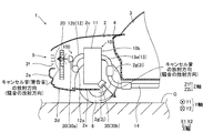
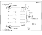
- 1 is a side view schematically showing a vehicle equipped with an engine noise reduction device according to a first embodiment of the present invention. It is the cross-sectional view which showed the inside of the engine room of the engine noise reduction apparatus by 1st Embodiment of this invention. It is the longitudinal section showing the inside of the engine room of the engine noise reduction device by a 1st embodiment of the present invention. It is the longitudinal section showing the inside of the engine room of the engine noise reduction device by a 1st embodiment of the present invention. It is the bottom view seen from the bottom of vehicles carrying the engine noise reduction device by a 1st embodiment of the present invention. 1 is a block diagram of an engine noise reduction device according to a first embodiment of the present invention.
- a vehicle 1 equipped with an engine noise reduction device 100 (an example of a vehicle power source noise reduction device) according to a first embodiment of the present invention will be described with reference to FIGS.
- the front of the traveling direction (X-axis direction) of the vehicle 1 is the X1 direction
- the rear is the X2 direction.
- the upper direction in the direction perpendicular to the ground G (see FIG. 1) Z-axis direction
- the lower direction ground G side
- one side of the width direction (Y-axis direction) of the vehicle 1 orthogonal to the X-axis direction and the Z-axis direction is defined as the Y1 direction
- the other side is defined as the Y2 direction.
- FIG. 1 A so-called FF drive type vehicle 1 on which the engine noise reduction device 100 according to the first embodiment of the present invention is mounted, as shown in FIG. 1, an engine room 2 in which an engine 10 for driving the vehicle 1 is accommodated ( An example of a housing part) and a vehicle interior 3 provided behind the engine room 2 are provided.
- the vehicle interior 3 is a vehicle interior space in which a seat 3a is arranged and a driver and a passenger (not shown) get on the vehicle.
- the engine room 2 and the vehicle interior 3 are partitioned by a dashboard 4.
- a soundproofing material (not shown) for sound insulation is attached to the dashboard 4 on the engine room 2 side.
- the vehicle 1 further includes a steering unit 5 and four wheels 6 for changing the traveling direction of the vehicle 1 when the direction is changed by the steering unit 5.
- the steering unit 5 includes a steering wheel 5 a operated by a driver, a steering shaft 5 b extending forward and downward from the steering wheel 5 a toward the engine room 2, and a pair of wheels 6 extending in the width direction and in front of the vehicle 1.
- a steering rod 5c connected to the gearbox 5 and a gear box 5d are included.
- the gear box 5d connects the steering shaft 5b and the steering rod 5c.
- the vehicle 1 further includes a suspension 8 that is disposed between the wheel 6 and the body (frame 7) and that reduces vibration from the ground G transmitted to the body.
- the suspension 8 includes a coil spring 8a disposed in the vicinity of the wheel 6, and an arm portion 8b (see FIG. 2) extending from the wheel 6 toward the engine room 2 and connected to the coil spring 8a and the frame 7. .
- the engine room 2 includes a bumper 2a disposed in the front (X1 direction), a pair of side panels 2b disposed in both sides (Y1 and Y2 directions), and a rear ( It is formed by being surrounded by the dashboard 4 arranged in the (X2 direction), the bonnet 2c arranged in the upper direction (Z1 direction), and the under covers 2d and 2e arranged in the lower direction. That is, both side portions in the Y-axis direction of the engine room 2 are each constituted by a pair of side panels 2b, and the bottom portion of the engine room 2 is constituted by undercovers 2d and 2e.
- the bumper 2a, the pair of side panels 2b, the dashboard 4, the bonnet 2c, and the under covers 2d and 2e are attached to the frame 7.
- a front grill 9 is arranged between the bumper 2a and the bonnet 2c.
- a four-cylinder in-line engine 10 in which four cylinders are arranged in the width direction (Y-axis direction) (hereinafter abbreviated as the engine 10 is an example of a vehicle power source).
- the engine 10 is an example of a vehicle power source.
- a radiator 20 for cooling the engine coolant that is connected to the engine 10 and circulates in the engine 10 is housed.
- the engine 10 is provided to drive the vehicle 1, and is disposed in the approximate center of the engine room 2.
- the radiator 20 is disposed in front of the engine 10 and behind the front grill 9.
- the radiator 20 has a function of cooling the engine coolant with the air taken in from the front grill 9.
- an engine room 2 and an opening 2f are formed on the front grille 9 on the opposite side (front) of the vehicle 1 to the inside 3 of the vehicle. Further, between the pair of side panels 2b disposed on both sides (Y1 and Y2 directions) and the bottom (the Z2 direction side portion) and the rear portion (the X2 direction side portion) under cover 2e. Has an opening 2g (an example of a second opening). The opening 2f and the opening 2g communicate the engine room 2 and the outside of the vehicle (the outside of the vehicle 1).
- the opening 2 f is formed in a lattice shape at the approximate center in the width direction of the vehicle 1 and the front grille 9.
- the opening 2f is formed in front of the engine body 11 of the engine 10 (X1 direction).
- the opening 2 f is provided for taking air into the engine room 2 from the front of the vehicle 1.
- the opening 2g includes opening portions 2h and 2i formed on one side and the other side of the engine room 2 in the Y-axis direction, and the rear and bottom of the engine room 2, respectively. It has the opening parts 2j and 2k formed over the whole width direction.
- the opening 2j is formed on the Y1 direction side of the bottom of the engine room 2, and the opening 2k is formed on the Y2 direction side of the bottom of the engine room 2. Further, the opening portions 2h to 2k of the opening 2g communicate with each other.
- the openings 2h and 2i are both provided for connecting the steering rod 5c and the wheel 6 and for drawing the arm 8b of the suspension 8 into the engine room 2.
- openings 2j and 2k at the bottom of the engine room 2 are provided to guide the exhaust duct 14 from the engine room 2 to the outside of the vehicle.
- the opening 2g is provided for discharging air taken from the front grill 9 into the engine room 2 to the outside of the vehicle.
- the engine 10 is provided with four cylinders 10a, and an engine body 11 in which intake, compression, expansion (combustion), and exhaust processes are continuously performed in the cylinder, and an intake manifold 12 ( And an exhaust manifold 13 (an example of an exhaust merging pipe).
- the intake manifold 12 is connected to an intake duct (not shown).
- the exhaust manifold 13 is connected to the exhaust duct 14.
- the exhaust duct 14 extends rearward at the bottom of the vehicle 1.
- the intake manifold 12 includes a surge tank 12a and four branch pipes 12b branched from the surge tank 12a. Each of the four branch pipes 12b has a function of supplying (distributing) intake air to the corresponding four cylinders 10a.
- the exhaust manifold 13 includes four branch pipes 13a. Each of the four branch pipes 13 a has a function of collecting exhaust from the corresponding four cylinders 10 a in the exhaust duct 14.
- various sounds are generated as noise. Specifically, a sound caused by explosion sound, intake pulsation, or the like in the engine body 11 in the expansion (combustion) process is generated as noise.
- the generated noise is radiated from the entire outer surface 10b in a radial direction away from the outer surface 10b of the engine 10, and leaks out of the vehicle mainly from the openings 2f and 2g of the engine room 2.
- the frequency and sound pressure of the noise change according to the driving state of the engine 10. The changes in frequency and sound pressure due to noise are mainly caused by the engine speed and the engine load factor.
- the vehicle 1 is equipped with an engine noise reduction device 100 for reducing the noise of the engine 10.
- the engine noise reduction device 100 includes three (plural) speakers 30 (a front speaker 30a, a rear speaker 30b, and a rear side) that generate a canceling sound having a phase opposite to that of the noise emitted from the engine 10.
- the three speakers 30 are arranged in the engine room 2 as shown in FIG.
- the three speakers 30 have the same structure. Specifically, as shown in FIG. 7, the speaker 30 includes a speaker box 31, a coil 32, a magnet 33, and a diaphragm 34 (an example of a sound wave generator) disposed in the speaker box 31. is doing. In the speaker 30, when a current flows through the coil 32, the magnetic field of the magnet 33 vibrates the coil 32 and the diaphragm 34 connected to the coil 32. This vibration is configured to be radiated from the speaker box 31 as a sound wave.
- the speaker 30 is a speaker having general directivity, and has a front axis (an axis extending through the center of the diaphragm 34 and extending in a direction orthogonal to the diaphragm 34) of 90 degrees or more and 180 degrees. It has a directivity angle of less than 60 degrees (the angle at which the sound becomes 6 dB smaller than the sound pressure level of the front axis).
- the three speakers 30 are each configured to generate a canceling sound in a direction away from the outer surface 10 b of the engine 10. Yes. Further, the three speakers 30 are arranged so as to radiate a canceling sound toward either the opening 2f or 2g communicating the engine room 2 and the outside of the vehicle.
- a front speaker 30a (an example of a first speaker) corresponds to the opening 2f
- a rear speaker 30b (an example of a second speaker and one speaker) and a rear speaker 30c. (An example of the second speaker and the other speaker) corresponds to the opening 2g.
- the front speaker 30a is disposed in front of the engine 10 (X1 direction) and in the vicinity of the outer surface 10b of the engine 10 as shown in FIGS. Further, the front speaker 30 a is disposed in the vicinity of the opening 2 f formed in front of the engine room 2. The front speaker 30a is configured to generate a cancellation sound forward toward the opening 2f.
- the rear speaker 30b is disposed on one side in the width direction of the engine 10 (Y1 direction side) and in the vicinity of the outer surface 10b of the engine 10, as shown in FIGS. Further, the rear speaker 30b is disposed in the vicinity of the opening 2g formed behind and below the engine room 2. The rear speaker 30b is configured to generate a cancellation sound in the rear, lower, and Y1 directions toward the opening 2g.
- the rear speaker 30c is disposed on the other side in the width direction of the engine 10 (Y2 direction side) and in the vicinity of the outer surface 10b of the engine 10, as shown in FIGS. Further, the rear speaker 30c is disposed in the vicinity of the opening 2g.
- the rear speaker 30c is configured to generate a cancellation sound in the rear, lower, and Y2 directions toward the opening 2g of the engine room 2.
- the rear speaker 30b includes an opening portion 2h (an example of a first opening portion) on the Y1 direction side of the opening portion 2g in the side portion, and an opening portion 2g in the bottom portion.
- a canceling sound is generated toward the opening portion 2j (an example of the first opening portion) on the Y1 direction side.
- the rear speaker 30c includes an opening portion 2i (an example of a second opening portion) in the Y2 direction side of the opening portion 2g in the side portion, and an opening portion 2k (in the Y2 direction side in the opening portion 2g of the bottom portion).
- An example of the second opening portion is configured to generate a canceling sound.
- the plurality of speakers 30 since the plurality of speakers 30 generate canceling sounds in different directions, it is possible to suppress the canceling sounds from interfering with each other.
- the diaphragms 34 of the plurality of speakers 30 are each arranged at a distance L from the outer surface 10 b of the engine 10.
- the distance L satisfies L ⁇ min / 4, where ⁇ min is the minimum wavelength corresponding to the maximum noise frequency fmax. That is, the diaphragm 34 of the speaker 30 is disposed within a range less than a quarter distance of the minimum wavelength ⁇ min corresponding to the maximum noise frequency fmax from the outer surface 10b of the engine 10 (that is, in the vicinity of the outer surface 10b). ing.
- the noise radiation source and the cancellation sound radiation source can be reliably arranged in the vicinity.
- the output unit 40 includes an ECU (Engine Control Unit) 41 and an amplifier 42 that amplifies the signal.
- the ECU 41 has a function of controlling the entire engine 10.
- the ECU 41 is provided with a storage unit 43 including a ROM (Read Only Memory) and a RAM (Random Access Memory).
- the storage unit 43 includes a plurality of cancel sound data 43a corresponding to the cancel sound generated from the front speaker 30a, a plurality of cancel sound data 43b corresponding to the cancel sound generated from the rear speaker 30b, and the rear speaker 30c.
- a plurality of cancel sound data 43c corresponding to the cancel sound to be generated is stored.
- the cancel sound data 43a to 43c are cancel sound cancel data corresponding to noise at each engine load factor and each engine speed when both the engine load factor and the engine speed of the engine 10 are changed. It is.
- cancel sound data 43a corresponding to an engine load factor greater than 0% and equal to or less than 100% and an engine speed greater than 0 rpm and equal to or less than 6000 rpm (maximum rotation speed).
- To 43c are stored. For example, the cancel sound data 43a to 43c when the engine load factor is 20% and the engine speed is 4000 rpm, or the cancel sound when the engine load factor is 60% and the engine speed is 5000 rpm.
- Data 43a to 43c are stored.
- the cancellation sound data 43a to 43c are acquired in advance by the following method.
- the engine 10 and the three microphones are arranged in an anechoic chamber that is a space without wall surface echoes.
- the sound collecting positions of the three microphones are substantially matched with the positions of the diaphragms 34 of the front speaker 30a, the rear speaker 30b, and the rear speaker 30c.
- the engine sound (noise) at the time of driving the engine 10 with the engine load factor and engine speed which are measured is acquired with three microphones.
- cancel sound data 43a to 43c corresponding to the cancel sound at the engine load factor and the engine speed to be measured are acquired and stored in the storage unit 43. Is done.
- the ECU 41 cancels the cancel sound data 43a to 43c corresponding to the current engine speed and the engine load factor from the cancel sound data 43a to 43c (see FIG. 8) stored in the storage unit 43 when the vehicle travels. Is configured to get. Then, as shown in FIG. 6, the ECU 41 transmits the acquired cancel sound data 43a to 43c as signals to the front speaker 30a, the rear speaker 30b, and the rear speaker 30c via the amplifier 42, respectively. It is configured. As a result, cancel sounds corresponding to the current engine speed and engine load factor are output from each of the front speaker 30a, the rear speaker 30b, and the rear speaker 30c.
- the storage unit 43 stores horn sound data 43d for generating a warning sound.
- the ECU 41 is configured to transmit the horn sound data 43d stored in the storage unit 43 as a signal to the front speaker 30a when an instruction to generate a warning sound is issued from the driver. As a result, a warning sound is generated from the front speaker 30a disposed in front of the engine 10.
- the front speaker 30a also serves as the horn of the vehicle 1 that generates a warning sound.
- the front speaker 30a is configured to generate a warning sound while generating a canceling sound.
- the speaker 30 is arranged in the direction along the radiation direction of the noise radiated from the engine 10 and the opening 2f provided in the engine room 2 in which the engine 10 is housed. It arrange
- the canceling sound can be radiated out of the vehicle from the openings 2f and 2g of the engine room 2
- noise leaking out of the vehicle can be reduced.
- the noise that leaks out of the vehicle from the openings 2f and 2g of the engine room 2 that tends to have a large sound pressure compared to the noise that leaks out of the vehicle from the portions other than the openings 2f and 2g of the engine room 2 is reduced.
- the canceling sound radiated toward 2g can be effectively reduced. As a result, noise leaking out of the vehicle can be sufficiently reduced.
- the front speaker 30a among the plurality of speakers 30 is associated with the opening 2f among the plurality of openings provided in the engine room 2 and canceled toward the corresponding opening 2f. Arrange to emit sound.
- the rear speaker 30b and the rear speaker 30c among the plurality of speakers 30 are associated with the opening 2g among the plurality of openings provided in the engine room 2 and canceled toward the corresponding opening 2g. Arrange to emit sound.
- noise leaking out of the vehicle from each of the plurality of openings 2f and 2g can be effectively reduced by the canceling sound radiated from the corresponding speaker 30, so that the noise leaking out of the vehicle can be sufficiently and reliably detected. Can be reduced.
- the front speaker 30a is disposed so as to radiate a canceling sound toward the opening 2f formed on the opposite side (front) of the vehicle 1 of the vehicle 1 in the engine room 2.
- the rear speaker 30b and the rear speaker 30c are arranged so as to radiate a canceling sound toward the opening 2g formed at the bottom of the engine room 2.
- the opening 2g is formed across the bottom and both sides of the engine room 2.
- the rear speaker 30b is disposed so as to radiate a canceling sound toward the opening portions 2h and 2j formed over the one side portion of the side portion and the bottom portion of the one side portion of the opening portion 2g.
- the rear speaker 30c is arranged so as to radiate a canceling sound toward the opening portions 2i and 2k formed over the other side portion of the side portion and the bottom portion on the other side portion of the opening portion 2g. .
- the rear speaker 30b corresponding to the opening portions 2h and 2j of the opening 2g and the opening of the opening 2g
- the rear speaker 30c corresponding to the portions 2i and 2k noise leaking out of the vehicle from the opening 2g can be effectively reduced.
- the front speaker 30a is disposed in the vicinity of the opening 2f, and the rear speakers 30b and 30c are both disposed in the vicinity of the opening 2g.
- the canceling sound can be reliably radiated outside the vehicle from the speaker 30 disposed in the vicinity of the opening 2f or 2g, so that the noise leaking outside the vehicle can be sufficiently reduced.
- the front speaker 30a among the plurality of speakers 30 also serves as the horn of the vehicle 1 that generates a warning sound.
- the front speaker 30a among the plurality of speakers 30 also serves as the horn of the vehicle 1 that generates a warning sound.
- the engine 10 includes an engine main body 11, an intake manifold 12 and an exhaust manifold 13 connected to the engine main body 11.
- the speaker 30 is emitted from the engine 10.
- the canceling sound is radiated in the direction along the radiation direction of the noise and toward the openings 2f and 2g communicating the engine room 2 and the outside of the vehicle. Thereby, the noise leaking out of the vehicle can be sufficiently reduced.
- the opening 2 f formed on the opposite side (front) of the engine room 2 to the vehicle interior 3 of the vehicle 1 takes air from the front of the vehicle 1 of the front grill 9 into the engine room 2.
- An opening 2g formed at the bottom of the engine room 2 includes an opening for the steering rod 5c and the suspension 8 of the vehicle 1, an opening for the exhaust duct 14 connected to the exhaust manifold 13, and an engine. It is an opening for releasing air in the room 2.
- the speaker 30 is disposed in the vicinity of the outer surface 10b of the engine 10. As a result, it is possible to suppress the occurrence of a large phase difference between the noise and the canceling sound, and thus it is possible to reliably suppress the strengthening of the noise and the canceling sound due to the large phase difference. is there.
- the diaphragm 34 of the speaker 30 is disposed within a range less than 1 ⁇ 4 distance of the minimum wavelength ⁇ min corresponding to the maximum noise frequency fmax from the outer surface 10b of the engine 10. Thereby, it is possible to reliably suppress a large phase difference between the noise and the canceling sound.
- a so-called RR drive type vehicle 201 includes an engine room 202 (an example of a storage unit) in which an engine 210 for driving the vehicle 201 is stored, as shown in FIGS. I have.
- the engine room 202 is formed behind the vehicle interior 3 (X2 direction).
- an opening 202f is formed in the rear portion (portion on the X2 direction side) of the engine room 202.
- the opening 202f is formed in a lattice shape at substantially the center in the width direction of the vehicle 201.
- an opening 202l is formed in the side and bottom (X2 direction) of the engine room 202 on the Y1 direction, and the side and bottom of the engine room 202 on the Y2 direction.
- An opening 202m is formed in the opening.
- the vehicle 201 is equipped with an engine noise reduction device 200 for reducing the noise of the engine 210.
- the engine noise reduction device 200 includes three (plural) speakers 230 (a rear speaker 230a, a front speaker 230b, and a front speaker 230c) that generate a canceling sound having a phase opposite to that of noise radiated from the engine 210. Note that the three speakers 230 are arranged in the engine room 202.
- Each of the three speakers 230 is configured to generate a canceling sound in a direction away from the outer surface 210b of the engine 210. Further, the three speakers 230 are arranged so as to emit a canceling sound toward the openings 202f, 202l, and 202m that communicate the engine room 202 with the outside of the vehicle.
- the rear speaker 230a corresponds to the opening 202f
- the front speaker 230b corresponds to the opening 202l
- the front speaker 230c corresponds to the opening 202m.
- the rear speaker 230a is arranged behind the engine 210 (X2 direction) and in the vicinity of the outer surface 210b of the engine 210. Further, the rear speaker 230 a is disposed in the vicinity of the opening 202 f formed at the rear of the engine room 202. The rear speaker 230a is configured to generate a cancellation sound forward toward the opening 202f.
- the front speaker 230 b is disposed on one side in the width direction of the engine 210 (Y1 direction side) and in the vicinity of the outer surface 210 b of the engine 210. Further, the front speaker 230b is disposed in the vicinity of the opening 202l formed in front of and below the engine room 202. The front speaker 230b is configured to generate a canceling sound downward and in the Y1 direction toward the opening 202l.
- the front speaker 230c is arranged on the other side (Y2 direction side) in the width direction of the engine 210 and in the vicinity of the outer surface 210b of the engine 210. Further, the front speaker 230c is disposed in the vicinity of the opening 202m formed in front of and below the engine room 202. The front speaker 230c is configured to generate a canceling sound downward and in the Y2 direction toward the opening 202m of the engine room 202.
- Other configurations of the second embodiment are the same as those of the first embodiment.
- the canceling sound is emitted from the speaker 230 in the direction along the radiation direction of the noise radiated from the engine 210 and toward the openings 202f and 202g provided in the engine room 202. To radiate. Thereby, the noise which leaks out of a vehicle can be fully reduced like 1st Embodiment.
- the rear speaker 230a, the front speaker 230b, and the front speaker 230c are arranged so as to radiate a cancellation sound toward the openings 202f, 202l, and 202m of the engine room 202, respectively.
- the noise leaking out of the vehicle through the opening 202f of the engine room 202 can be effectively reduced by the canceling sound from the rear speaker 230a radiated toward the opening 202f.
- the noise leaking out of the vehicle from the openings 202l and 202m of the engine room 202 is more effective due to the canceling sound from the front speaker 230b and the canceling sound from the front speaker 230c radiated toward the openings 202l and 202m, respectively.
- the remaining effects of the second embodiment are similar to those of the first embodiment.
- the present invention is not limited to this.
- the vehicle power source noise reduction device may be used to reduce noise of a multi-cylinder engine other than the in-line four-cylinder engine, a V-type multi-cylinder engine, or the like.
- the vehicle power source noise reduction device may be used to reduce the noise of an engine mounted on, for example, equipment other than that for automobiles that needs to reduce noise.
- the vehicle power source is not limited to the engine, and may be a motor, for example.
- the number of vehicle power sources is not limited to one, and a vehicle power source noise reduction device may be used so as to reduce the noise of two or more vehicle power sources.
- a vehicle power source noise reduction device may be used so as to reduce the noise of both the engine and the motor.
- the vehicle power source noise reduction device may further include a sound collector that collects noise radiated from the vehicle power source.
- the vehicle power source noise reduction device corrects the deviation when the deviation amount between the noise collected by the sound collector and the reference noise (for example, initial vehicle power source noise) exceeds a deviation threshold.
- You may comprise as follows. In this case, it is preferable that the microphone can preferentially collect noise from the vehicle power source.
- different speakers having different directivities or different frequency characteristics may be used as the three speakers 30 (230) in the first or second embodiment.
- the storage unit 43 stores cancel sound data 43a to 43 corresponding to engine load factors greater than 0% and less than or equal to 100% and engine speeds greater than 0 rpm and less than or equal to 6000 rpm (maximum rotation speed).
- maximum rotation speed may be changed depending on the performance of the vehicle power source.
- the cancel sound data may be stored in accordance with parameters other than the load factor and the rotational speed (for example, throttle opening degree, etc.).
- the cancel sound data 43a to 43c are stored in the storage unit 43 in units of 5% for the engine load factor and in units of 50 rpm for the engine speed, respectively.
- the present invention is not limited to this.
- the number of cancel sound data may be changed as appropriate according to the desired degree of noise reduction.
- the three speakers 30 (230) are arranged in the vicinity of the outer surface 10b (210b) of the engine 10 (210) in the engine room 2 (202, accommodating portion).
- the present invention is not limited to this.
- the speaker only needs to be disposed in the housing portion, and the speaker may be disposed at a position away from the outer surface of the engine.
- the example using the three speakers 30 (230) is shown, but the present invention is not limited to this.
- the number of speakers may be one, two, or four or more.
- the example is shown in which the front speaker 30a is associated with the opening 2f and the rear speakers 30b and 30c are associated with the opening 2g.
- the rear speaker 230a is associated with the opening 202f
- the front speaker 230b is associated with the opening 202l
- the front speaker 230b is associated with the opening 202m.
- one speaker may correspond to a plurality of openings by configuring one speaker to emit a canceling sound toward the plurality of openings.
- the present invention is not limited to this. I can't.
- one or three or more speakers may be used for a large opening. Note that the number of speakers can be reduced by using a speaker having a wide directivity (a large directivity angle) for a large opening.
- the speaker may be an omnidirectional speaker as long as the canceling sound can be emitted toward the opening. Note that it is preferable to use a speaker having directivity in order to prevent the canceling sound from moving to other than the opening.
- the vehicle may be a so-called FR drive system.
- the speaker of the vehicle power source noise reduction device is arranged together with the vehicle power source in a housing portion formed in front of the vehicle interior, as in the first embodiment.
- the vehicle may be a so-called MR drive system.
- the speaker of the vehicle power source noise reduction device is disposed together with the vehicle power source in a housing portion formed at the rear of the vehicle interior, as in the second embodiment.
- emits cancellation sound in the opening part 2f formed in the front, a side, back, and the downward direction
- An opening 2g formed over the surface is shown as an example.
- the opening from which the speaker 230 emits the canceling sound the opening 202f formed at the rear and the openings 202l and 202m formed across the side and the lower side are exemplified.
- the present invention is not limited to this.
- the opening where the speaker emits the canceling sound is not particularly limited as long as the opening is an opening that communicates the housing portion with the outside of the vehicle. For example, if there is an opening between the side panel and the bonnet that communicates the housing and the outside of the vehicle, the vehicle emits a canceling sound toward the opening between the side panel and the bonnet.
- a power source noise reduction device may be configured.
- a speaker that does not emit cancellation sound toward the opening may be newly provided.
- the newly provided speaker is provided in the vicinity of the outer surface of the vehicle power source.
Landscapes
- Engineering & Computer Science (AREA)
- Mechanical Engineering (AREA)
- Physics & Mathematics (AREA)
- Acoustics & Sound (AREA)
- Multimedia (AREA)
- Fittings On The Vehicle Exterior For Carrying Loads, And Devices For Holding Or Mounting Articles (AREA)
- Soundproofing, Sound Blocking, And Sound Damping (AREA)
Abstract
この車両動力源騒音低減装置は、車両を駆動させるための車両動力源が収容される収容部内に配置され、車両動力源から放射される騒音を低減する、騒音とは逆位相のキャンセル音を発生させるスピーカを備える。スピーカは、車両動力源から放射される騒音の放射方向に沿った方向で、かつ、収容部と車外とを連通する開口部に向かってキャンセル音を放射するように配置されている。
Description
本発明は、車両動力源騒音低減装置に関し、特に、車両動力源から放射される騒音を低減する車両動力源騒音低減装置に関する。
従来、車両動力源から放射される騒音を低減する車両動力源騒音低減装置が知られている。このような車両動力源騒音低減装置は、たとえば、特開平2-306845号公報に開示されている。
特開平2-306845号公報には、エンジンが収容されるエンジン収容部(エンジンルーム)よりも後方の車室内における運転者の耳元(受聴点)において、エンジンの爆発に起因する騒音を低減する、車室内騒音の低減装置が開示されている。この車室内騒音の低減装置は、車室内に設けられたスピーカと、受聴点における騒音を低減するように音の位相および音圧を調整して、スピーカに出力する制御手段とを備えている。
しかしながら、特開平2-306845号公報に記載された車室内騒音の低減装置では、受聴点である車室の一地点において、エンジンに起因する騒音を低減することが可能である一方、エンジン収容部(エンジンルーム)から車外に漏れ出る騒音は低減されないという不都合がある。このため、車両の外部(車外)に漏れ出る騒音を十分に低減することができないという問題点がある。
この発明は、上記のような課題を解決するためになされたものであり、この発明の1つの目的は、車外に漏れ出る騒音を十分に低減することが可能な車両動力源騒音低減装置を提供することである。
上記目的を達成するために、この発明の一の局面における車両動力源騒音低減装置は、車両を駆動させるための車両動力源が収容される収容部内に配置され、車両動力源から放射される騒音を低減する、騒音とは逆位相のキャンセル音を発生させるスピーカを備え、スピーカは、車両動力源から放射される騒音の放射方向に沿った方向で、かつ、収容部と車外とを連通する開口部に向かってキャンセル音を放射するように配置されている。
この発明の一の局面による車両動力源騒音低減装置では、上記のように、スピーカは、車両動力源から放射される騒音の放射方向に沿った方向で、かつ、車両動力源が収容される収容部に設けられた開口部に向かってキャンセル音を放射するように配置されている。これにより、収容部の開口部からキャンセル音を車外に放射することができるので、車外に漏れ出る騒音を低減することができる。また、収容部の開口部以外の部分から車外に漏れ出る騒音に比べて、大きな音圧になりやすい収容部の開口部から車外に漏れ出る騒音を、開口部に向かって放射されるキャンセル音により効果的に低減することができる。これらの結果、車外に漏れ出る騒音を十分に低減することができる。
上記一の局面による車両動力源騒音低減装置において、好ましくは、スピーカは、複数設けられており、複数のスピーカは、各々、収容部に設けられた複数の開口部の各々に対応付けられており、対応する開口部に向かってキャンセル音を放射するように配置されている。
このように構成すれば、複数の開口部の各々から車外に漏れ出る騒音を、対応するスピーカから放射されるキャンセル音により効果的に低減することができるので、車外に漏れ出る騒音を十分かつ確実に低減することができる。
この場合、好ましくは、収容部の開口部は、収容部の車両の室内とは反対側に形成された第1開口部と、収容部の少なくとも底部に形成された第2開口部とを含み、複数のスピーカは、第1開口部に向かってキャンセル音を放射するように配置された第1スピーカと、第2開口部に向かってキャンセル音を放射するように配置された第2スピーカとを含む。
このように構成すれば、収容部の車両の室内とは反対側に形成された第1開口部、および、収容部の少なくとも底部に形成された第2開口部から車外に漏れ出る騒音を、それぞれ、対応する第1スピーカおよび第2スピーカから放射されるキャンセル音により効果的に低減することができる。
上記複数のスピーカが第2スピーカを含む構成において、好ましくは、第2開口部は、収容部の底部と側部とに亘って形成されており、第2スピーカは、第2開口部のうち、側部の一方側部および一方側部側の底部に亘って形成された第1開口部分に向かってキャンセル音を放射するように配置された一方スピーカと、第2開口部のうち、側部の他方側部および他方側部側の底部に亘って形成された第2開口部分に向かってキャンセル音を放射するように配置された他方スピーカとを有する。
このように構成すれば、収容部の底部と側部とに亘って形成された大きな第2開口部であっても、第2開口部の第1開口部分に対応する一方スピーカと、第2開口部の第2開口部分に対応する他方スピーカによって、第2開口部から車外に漏れ出る騒音を効果的に低減することができる。
上記一の局面による車両動力源騒音低減装置において、好ましくは、スピーカは、開口部の近傍に配置されている。
このように構成すれば、開口部の近傍に配置されたスピーカからキャンセル音を車外に確実に放射することができるので、車外に漏れ出る騒音を十分に低減することができる。また、スピーカから放射されるキャンセル音の一部が、開口部から車外に出ずに、収容部内で反射するのを抑制することができる。これにより、収容部内での反射に起因して反射したキャンセル音の位相が開口部から出る際に変化するのを抑制することができるので、位相の変化に起因して騒音の低減が行えなくなるのを抑制することができる。この結果、騒音の低減を確実に行うことができる。
上記一の局面による車両動力源騒音低減装置において、好ましくは、複数のスピーカのうちのいずれかは、警告音を発生させる車両のホーンを兼ねる。
このように構成すれば、ホーンを車両動力源騒音低減装置とは別個に設ける必要がないので、車両動力源騒音低減装置が設けられた車両において、部品点数が増加するのを抑制することができる。
上記一の局面による車両動力源騒音低減装置において、好ましくは、車両動力源は、エンジン本体と、エンジン本体に接続される吸気分配管および排気合流管とを有するエンジンを含む。
このようなエンジンを備える車両において、エンジン、吸気分配管および排気合流管に起因する騒音がエンジンから放射される場合であっても、スピーカを、エンジンから放射される騒音の放射方向に沿った方向、かつ、エンジンルームと車外とを連通する開口部に向かってにキャンセル音を放射するように配置することによって、車外に漏れ出る騒音を十分に低減することができる。
上記開口部が第1開口部と第2開口部とを含む構成において、好ましくは、車両動力源は、エンジン本体と、エンジン本体に接続される吸気分配管および排気合流管とを有するエンジンを含み、第1開口部は、車両のフロントグリルの開口部であり、第2開口部は、車両のステアリングロッドまたはサスペンションのための開口部、排気合流管に接続される排気ダクトのための開口部、および、収容部内の空気を放出するための開口部の少なくともいずれかである。
このように構成すれば、エンジンを備える車両においてエンジンを駆動させて駆動力を駆動機構に伝えるために開口部が形成されている場合において、開口部から車外に漏れ出る騒音を、開口部に向かってキャンセル音を放射するスピーカにより十分に低減することができる。
上記一の局面による車両動力源騒音低減装置において、好ましくは、スピーカは、車両動力源の外表面近傍に配置されている。
このように構成すれば、騒音とキャンセル音との間に大きな位相差が生じるのを抑制することができるので、大きな位相差に起因して騒音とキャンセル音とが強め合うのを確実に抑制することができる。
この場合、好ましくは、スピーカのキャンセル音を発生させる音波発生部は、車両動力源の外表面から、騒音の最大周波数に対応する最小波長の1/4の距離未満の範囲内に配置されている。
このように構成すれば、騒音とキャンセル音との間に大きな位相差が生じるのを確実に抑制することができる。
以下、本発明の実施形態を図面に基づいて説明する。
(第1実施形態)
図1~図8を参照して、本発明の第1実施形態によるエンジン騒音低減装置100(車両動力源騒音低減装置の一例)が搭載される車両1について説明する。なお、第1実施形態では、車両1の走行方向(X軸方向)の前方をX1方向とし、後方をX2方向とする。また、地面G(図1参照)に対して垂直な方向(Z軸方向)の上方をZ1方向とし、下方(地面G側)をZ2方向とする。また、X軸方向およびZ軸方向と直交する車両1の幅方向(Y軸方向)の一方側をY1方向とし、他方側をY2方向とする。
図1~図8を参照して、本発明の第1実施形態によるエンジン騒音低減装置100(車両動力源騒音低減装置の一例)が搭載される車両1について説明する。なお、第1実施形態では、車両1の走行方向(X軸方向)の前方をX1方向とし、後方をX2方向とする。また、地面G(図1参照)に対して垂直な方向(Z軸方向)の上方をZ1方向とし、下方(地面G側)をZ2方向とする。また、X軸方向およびZ軸方向と直交する車両1の幅方向(Y軸方向)の一方側をY1方向とし、他方側をY2方向とする。
(車両の構成)
本発明の第1実施形態によるエンジン騒音低減装置100が搭載されるいわゆるFF駆動方式の車両1は、図1に示すように、車両1を駆動させるためのエンジン10が収容されるエンジンルーム2(収容部の一例)と、エンジンルーム2よりも後方に設けられた車内3とを備えている。車内3は、シート3aが配置されており、図示しない運転者および搭乗者が乗車する車内空間である。エンジンルーム2と車内3とは、ダッシュボード4により区画されている。ダッシュボード4のエンジンルーム2側には、遮音のための防音材(図示せず)が取り付けられている。
本発明の第1実施形態によるエンジン騒音低減装置100が搭載されるいわゆるFF駆動方式の車両1は、図1に示すように、車両1を駆動させるためのエンジン10が収容されるエンジンルーム2(収容部の一例)と、エンジンルーム2よりも後方に設けられた車内3とを備えている。車内3は、シート3aが配置されており、図示しない運転者および搭乗者が乗車する車内空間である。エンジンルーム2と車内3とは、ダッシュボード4により区画されている。ダッシュボード4のエンジンルーム2側には、遮音のための防音材(図示せず)が取り付けられている。
また、車両1は、ステアリング部5と、ステアリング部5により向きが変化されることによって、車両1の走行方向を変更するための4個の車輪6とをさらに備えている。ステアリング部5は、運転者により操作されるステアリングホイール5aと、ステアリングホイール5aからエンジンルーム2に向かって前方および下方に延びるステアリングシャフト5bと、幅方向に延び、車両1の前方の一対の車輪6に接続されるステアリングロッド5cと、ギアボックス5dとを含んでいる。ギアボックス5dは、ステアリングシャフト5bとステアリングロッド5cとを接続している。
また、車両1は、車輪6とボディ(フレーム7)との間に配置され、ボディに伝達される地面Gからの振動を低減するサスペンション8をさらに備えている。サスペンション8は、車輪6近傍に配置されたコイルスプリング8aと、車輪6からエンジンルーム2に向かって延び、コイルスプリング8aおよびフレーム7に接続されるアーム部8b(図2参照)とを含んでいる。
また、エンジンルーム2は、図1および図2に示すように、前方(X1方向)に配置されたバンパー2a、両側方(Y1およびY2方向)にそれぞれ配置された一対のサイドパネル2b、後方(X2方向)に配置されたダッシュボード4、上方(Z1方向)に配置されたボンネット2c、および、下方に配置されたアンダーカバー2dおよび2eとにより取り囲まれることにより形成されている。つまり、エンジンルーム2のY軸方向の両側部は、それぞれ、一対のサイドパネル2bにより構成されているとともに、エンジンルーム2の底部は、アンダーカバー2dおよび2eにより構成されている。
なお、バンパー2a、一対のサイドパネル2b、ダッシュボード4、ボンネット2c、アンダーカバー2dおよび2eは、フレーム7に取り付けられている。また、バンパー2aとボンネット2cとの間には、フロントグリル9が配置されている。
エンジンルーム2内には、図2~図5に示すように、4個の気筒が幅方向(Y軸方向)に並ぶ4気筒直列エンジン10(以降、エンジン10と省略する、車両動力源の一例)と、エンジン10に接続され、エンジン10内を流通するエンジン冷却水を冷却するためのラジエータ20とが収容されている。エンジン10は、車両1を駆動させるために設けられており、エンジンルーム2の略中央に配置されている。ラジエータ20は、エンジン10の前方で、かつ、フロントグリル9の後方に配置されている。ラジエータ20は、フロントグリル9から取り込まれた空気により、エンジン冷却水を冷却する機能を有している。
また、車両1の車内3とは反対側(前方)のフロントグリル9には、エンジンルーム2と開口部2f(第1開口部の一例)が形成されている。さらに、両側方(Y1およびY2方向)にそれぞれ配置された一対のサイドパネル2bと、底部(Z2方向側の部分)で、かつ、後部(X2方向側の部分)のアンダーカバー2eとの間には、開口部2g(第2開口部の一例)が形成されている。これら開口部2fおよび開口部2gは、エンジンルーム2と車外(車両1の外部)とを連通している。
開口部2fは、車両1およびフロントグリル9における幅方向の略中央に格子状に形成されている。なお、開口部2fは、エンジン10のエンジン本体11よりも前方(X1方向)に形成されている。また、開口部2fは、車両1の前方からエンジンルーム2内に空気を取り込むために設けられている。
開口部2gは、エンジンルーム2のY軸方向の一方方向側の側部および他方方向側の側部にそれぞれ形成された開口部分2hおよび2iと、エンジンルーム2の後部で、かつ、底部において、幅方向の全体に亘って形成された開口部分2jおよび2kとを有している。開口部分2jは、エンジンルーム2の底部のY1方向側に形成され、開口部分2kは、エンジンルーム2の底部のY2方向側に形成されている。また、開口部2gの開口部分2h~2kは、連通している。
また、開口部2gのうち、開口部分2hおよび2iは、共に、ステアリングロッド5cと車輪6とを接続するとともに、サスペンション8のアーム部8bをエンジンルーム2内に引き込むために設けられている。開口部2gのうち、エンジンルーム2の底部における開口部分2jおよび2kは、排気ダクト14をエンジンルーム2から車外に導くために設けられている。また、開口部2gは、フロントグリル9からエンジンルーム2内に取り込まれた空気を車外に排出するために設けられている。
エンジン10は、4個の気筒10aが設けられ、気筒において吸気、圧縮、膨張(燃焼)および排気の各工程が連続して行われるエンジン本体11と、エンジン本体11に接続されるインテークマニホールド12(吸気分配管の一例)およびエキゾーストマニホールド13(排気合流管の一例)とを含んでいる。
インテークマニホールド12は、図示しない吸気ダクトに接続されている。エキゾーストマニホールド13は、排気ダクト14に接続されている。排気ダクト14は、車両1の底部において後方に向かって延びている。
インテークマニホールド12は、サージタンク12aと、サージタンク12aから分岐する4個の分岐管12bとを含んでいる。4個の分岐管12bは、それぞれ、対応する4個の気筒10aに吸気を供給(分配)する機能を有している。エキゾーストマニホールド13は、4個の分岐管13aを含んでいる。4個の分岐管13aは、それぞれ、対応する4個の気筒10aからの排気を排気ダクト14に集合させる機能を有している。
なお、エンジン10では、様々な音が騒音として発生している。具体的には、膨張(燃焼)工程におけるエンジン本体11内での爆発音、吸気脈動等に起因する音などが騒音として発生する。発生した騒音は、エンジン10の外表面10bから離れる放射方向に向かって外表面10bの全面から放射されて、主にエンジンルーム2の開口部2fおよび2gから車外に漏れ出る。なお、騒音は、エンジン10の駆動状態に応じて、周波数および音圧が変化する。そして、騒音における周波数および音圧の変化は、主にエンジン回転数およびエンジン負荷率に起因する。
ここで、第1実施形態では、車両1には、エンジン10の騒音を低減させるためのエンジン騒音低減装置100が搭載されている。エンジン騒音低減装置100は、図6に示すように、エンジン10から放射される騒音と逆位相のキャンセル音を発生させる3個(複数)のスピーカ30(前側スピーカ30a、後側スピーカ30b、後側スピーカ30c)と、スピーカ30にキャンセル音を発生させるための出力部40とを含んでいる。なお、3個のスピーカ30は、図2に示すように、エンジンルーム2内に配置されている。
3個のスピーカ30は、等しい構造を有している。具体的には、図7に示すように、スピーカ30は、スピーカボックス31と、スピーカボックス31内に配置されたコイル32、マグネット33、および、振動板34(音波発生部の一例)とを有している。スピーカ30では、コイル32に電流が流れた際に、マグネット33の磁界により、コイル32およびコイル32に接続された振動板34とが振動する。この振動が音波として、スピーカボックス31から放射されるように構成されている。なお、このスピーカ30は、一般的な指向性を有するスピーカであり、正面軸(振動板34の中心を通り、振動板34に対して直交する方向に延びる軸)を中心として、90度以上180度以下の指向角度(正面軸の音圧レベルより6dB音が小さくなる位置の角度)を有している。
ここで、第1実施形態では、図2~図5に示すように、3個のスピーカ30は、各々、エンジン10の外表面10bから離れる方向に向かってキャンセル音を発生させるように構成されている。さらに、3個のスピーカ30は、エンジンルーム2と車外とを連通する開口部2fまたは2gのいずれかに向かってキャンセル音を放射するように配置されている。なお、3個のスピーカ30のうち、前側スピーカ30a(第1スピーカの一例)は、開口部2fに対応しており、後側スピーカ30b(第2スピーカおよび一方スピーカの一例)および後側スピーカ30c(第2スピーカおよび他方スピーカの一例)は、開口部2gに対応している。
具体的には、前側スピーカ30aは、図2~図4に示すように、エンジン10の前方(X1方向)で、かつ、エンジン10の外表面10b近傍に配置されている。さらに、前側スピーカ30aは、エンジンルーム2の前方に形成された開口部2f近傍に配置されている。そして、前側スピーカ30aは、開口部2fに向かって前方にキャンセル音を発生させるように構成されている。
後側スピーカ30bは、図2、図4および図5に示すように、エンジン10の幅方向の一方側(Y1方向側)で、かつ、エンジン10の外表面10b近傍に配置されている。さらに、後側スピーカ30bは、エンジンルーム2の後方かつ下方に形成された開口部2g近傍に配置されている。そして、後側スピーカ30bは、開口部2gに向かって、後方、下方、かつ、Y1方向にキャンセル音を発生させるように構成されている。
後側スピーカ30cは、図2、図3および図5に示すように、エンジン10の幅方向の他方側(Y2方向側)で、かつ、エンジン10の外表面10b近傍に配置されている。さらに、後側スピーカ30cは、開口部2g近傍に配置されている。そして、後側スピーカ30cは、エンジンルーム2の開口部2gに向かって、後方、下方、かつ、Y2方向にキャンセル音を発生させるように構成されている。
なお、図2および図5に示すように、後側スピーカ30bは、側部における開口部2gのうちのY1方向側の開口部分2h(第1開口部分の一例)と、底部における開口部2gのうちのY1方向側の開口部分2j(第1開口部分の一例)とに向かってキャンセル音を発生させるように構成されている。また、後側スピーカ30cは、側部における開口部2gのうちのY2方向側の開口部分2i(第2開口部分の一例)と、底部における開口部2gのうちのY2方向側の開口部分2k(第2開口部分の一例)とに向かってキャンセル音を発生させるように構成されている。
また、複数のスピーカ30がそれぞれ異なる方向に向かってキャンセル音を発生させることによって、キャンセル音が互いに干渉するのを抑制することが可能である。
また、図7に示すように、複数のスピーカ30の振動板34は、各々、エンジン10の外表面10bから距離Lの位置に配置されている。なお、距離Lは、騒音の最大周波数fmaxに対応する最小波長をλminとした場合に、L<λmin/4を満たしている。つまり、スピーカ30の振動板34は、エンジン10の外表面10bから、騒音の最大周波数fmaxに対応する最小波長λminの1/4の距離未満の範囲内(つまり、外表面10b近傍)に配置されている。これにより、騒音の放射源とキャンセル音の放射源とを近傍に確実に配置することが可能である。
出力部40は、図6に示すように、ECU(Engine Control Unit)41と、信号を増幅するアンプ42とを有している。ECU41は、エンジン10全体の制御を行う機能を有している。また、ECU41には、ROM(Read Only Memory)およびRAM(Ramdom Access Memory)などから構成される記憶部43が設けられている。記憶部43には、前側スピーカ30aから発生させるキャンセル音に対応する複数のキャンセル音データ43aと、後側スピーカ30bから発生させるキャンセル音に対応する複数のキャンセル音データ43bと、後側スピーカ30cから発生させるキャンセル音に対応する複数のキャンセル音データ43cとが記憶されている。
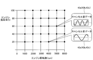
このキャンセル音データ43a~43cは、エンジン10のエンジン負荷率およびエンジン回転数の両方を変化させた場合の各々のエンジン負荷率および各々のエンジン回転数での騒音に対応するキャンセル音のキャンセル音データである。なお、記憶部43には、図8に示すように、0%より大きく100%以下のエンジン負荷率と、0rpmより大きく6000rpm(最大回転数)以下のエンジン回転数とに対応するキャンセル音データ43a~43cがそれぞれ記憶されている。たとえば、20%のエンジン負荷率で、かつ、4000rpmのエンジン回転数である場合のキャンセル音データ43a~43cや、60%のエンジン負荷率で、かつ、5000rpmのエンジン回転数である場合のキャンセル音データ43a~43cなどがそれぞれ記憶されている。
また、図8には詳細には記載していないものの、記憶部43において、キャンセル音データ43a~43cは、各々、エンジン負荷率に関しては5%刻み、エンジン回転数に関しては50rpm刻みで記憶されている。つまり、キャンセル音データ43a~43cは、各々、2400(=20×120)個、記憶部43に記憶されている。
ここで、キャンセル音データ43a~43cは、下記の方法で予め取得される。まず、図7に示すように、エンジン10および3個のマイクを、壁面反響のない空間である無響音室内に配置する。ここで、3個のマイクの集音位置を、前側スピーカ30a、後側スピーカ30bおよび後側スピーカ30cの振動板34の位置とそれぞれ略一致させる。そして、測定するエンジン負荷率およびエンジン回転数でエンジン10を駆動させた際のエンジン音(騒音)を、3個のマイクによって取得する。そして、取得した騒音の騒音データを逆位相の波形に変換することによって、測定するエンジン負荷率およびエンジン回転数におけるキャンセル音に対応するキャンセル音データ43a~43cが取得されて、記憶部43に記憶される。
そして、ECU41は、車両走行時に、記憶部43に記憶されたキャンセル音データ43a~43c(図8参照)の中から、現時点でのエンジン回転数およびエンジン負荷率に対応するキャンセル音データ43a~43cを取得するように構成されている。そして、ECU41は、図6に示すように、アンプ42を介して、取得したキャンセル音データ43a~43cを、それぞれ、前側スピーカ30a、後側スピーカ30bおよび後側スピーカ30cに信号として送信するように構成されている。この結果、前側スピーカ30a、後側スピーカ30bおよび後側スピーカ30cの各々から、現時点でのエンジン回転数およびエンジン負荷率に対応するキャンセル音が出力される。
また、記憶部43には、警告音を発生させるためのホーン音データ43dが記憶されている。ECU41は、運転者から警告音を発生させる指示が行われた場合には、記憶部43に記憶されたホーン音データ43dを前側スピーカ30aに信号として送信するように構成されている。これにより、エンジン10の前方に配置された前側スピーカ30aから、警告音が発生する。なお、前側スピーカ30aは、警告音を発生させる車両1のホーンを兼ねている。また、前側スピーカ30aは、キャンセル音を発生させながら、警告音を発生させることが可能に構成されている。
(第1実施形態の効果)
第1実施形態では、以下のような効果を得ることができる。
第1実施形態では、以下のような効果を得ることができる。
第1実施形態では、上記のように、スピーカ30を、エンジン10から放射される騒音の放射方向に沿った方向で、かつ、エンジン10が収容されるエンジンルーム2に設けられた開口部2fおよび2gに向かってキャンセル音を放射するように配置する。これにより、エンジンルーム2の開口部2fおよび2gからキャンセル音を車外に放射することができるので、車外に漏れ出る騒音を低減することができる。また、エンジンルーム2の開口部2fおよび2g以外の部分から車外に漏れ出る騒音に比べて、大きな音圧になりやすいエンジンルーム2の開口部2fおよび2gから車外に漏れ出る騒音を、開口部2fおよび2gに向かって放射されるキャンセル音により効果的に低減することができる。これらの結果、車外に漏れ出る騒音を十分に低減することができる。
また、第1実施形態では、複数のスピーカ30のうちの前側スピーカ30aを、エンジンルーム2に設けられた複数の開口部のうちの開口部2fに対応付けるとともに、対応する開口部2fに向かってキャンセル音を放射するように配置する。また、複数のスピーカ30のうちの後側スピーカ30bおよび後側スピーカ30cを、エンジンルーム2に設けられた複数の開口部のうちの開口部2gに対応付けるとともに、対応する開口部2gに向かってキャンセル音を放射するように配置する。これにより、複数の開口部2fおよび2gの各々から車外に漏れ出る騒音を、対応するスピーカ30から放射されるキャンセル音により効果的に低減することができるので、車外に漏れ出る騒音を十分かつ確実に低減することができる。
また、第1実施形態では、前側スピーカ30aを、エンジンルーム2の車両1の車内3とは反対側(前方)に形成された開口部2fに向かってキャンセル音を放射するように配置する。また、後側スピーカ30bおよび後側スピーカ30cを、エンジンルーム2の底部に形成された開口部2gに向かってキャンセル音を放射するように配置する。これらにより、エンジンルーム2の車両1の車内3とは反対側に形成された開口部2f、および、エンジンルーム2の底部に形成された開口部2gから車外に漏れ出る騒音を、それぞれ、対応する前側スピーカ30aならびに後側スピーカ30bおよび後側スピーカ30cから放射されるキャンセル音により効果的に低減することができる。
また、第1実施形態では、開口部2gを、エンジンルーム2の底部と両側部とに亘って形成する。そして、後側スピーカ30bを、開口部2gのうち、側部の一方側部および一方側部側の底部に亘って形成された開口部分2hおよび2jに向かってキャンセル音を放射するように配置する。また、後側スピーカ30cを、開口部2gのうち、側部の他方側部および他方側部側の底部に亘って形成された開口部分2iおよび2kに向かってキャンセル音を放射するように配置する。これらにより、エンジンルーム2の底部と側部とに亘って形成された大きな開口部2gであっても、開口部2gの開口部分2hおよび2jに対応する後側スピーカ30bと、開口部2gの開口部分2iおよび2kに対応する後側スピーカ30cによって、開口部2gから車外に漏れ出る騒音を効果的に低減することができる。
また、第1実施形態では、前側スピーカ30aを、開口部2fの近傍に配置し、後側スピーカ30bおよび30cを、共に、開口部2gの近傍に配置する。これにより、開口部2fまたは2gの近傍に配置されたスピーカ30からキャンセル音を車外に確実に放射することができるので、車外に漏れ出る騒音を十分に低減することができる。また、スピーカ30から放射されるキャンセル音の一部が、開口部2fおよび2gから車外に出ずに、エンジンルーム2内で反射するのを抑制することができる。これにより、収容部内での反射に起因して反射したキャンセル音の位相が開口部2fおよび2gから出る際に変化するのを抑制することができるので、位相の変化に起因して騒音の低減が行えなくなるのを抑制することができる。この結果、騒音の低減を確実に行うことができる。
また、第1実施形態では、複数のスピーカ30のうちの前側スピーカ30aが、警告音を発生させる車両1のホーンを兼ねる。これにより、ホーンをエンジン騒音低減装置100とは別個に設ける必要がないので、エンジン騒音低減装置100が設けられた車両1において、部品点数が増加するのを抑制することができる。
また、第1実施形態では、エンジン10は、エンジン本体11と、エンジン本体11に接続されるインテークマニホールド12およびエキゾーストマニホールド13とを有する。このようなエンジン本体11におけるピストンの上下運動に起因する音、インテークマニホールド12における吸気脈動等に起因する音などが騒音として、エンジン10から放射される場合に、スピーカ30を、エンジン10から放射される騒音の放射方向に沿った方向、かつ、エンジンルーム2と車外とを連通する開口部2fおよび2gに向かってにキャンセル音を放射するように配置する。これにより、車外に漏れ出る騒音を十分に低減することができる。
また、第1実施形態では、エンジンルーム2の車両1の車内3とは反対側(前方)に形成された開口部2fはフロントグリル9の車両1の前方からエンジンルーム2内に空気を取り込むための開口部である。また、エンジンルーム2の底部に形成された開口部2gは、車両1のステアリングロッド5cおよびサスペンション8のための開口部、エキゾーストマニホールド13に接続される排気ダクト14のための開口部、および、エンジンルーム2内の空気を放出するための開口部である。これらにより、エンジン10を備える車両1においてエンジン10を駆動させて駆動力を車輪6に伝えるために開口部2fおよび2gが形成されている場合において、開口部2fおよび2gから車外に漏れ出る騒音を、開口部2fおよび2gに向かってキャンセル音を放射するスピーカ30により十分に低減することができる。
また、第1実施形態では、スピーカ30を、エンジン10の外表面10b近傍に配置する。これにより、騒音とキャンセル音との間に大きな位相差が生じるのを抑制することができるので、大きな位相差に起因して騒音とキャンセル音とが強め合うのを確実に抑制することが可能である。
また、第1実施形態では、スピーカ30の振動板34を、エンジン10の外表面10bから、騒音の最大周波数fmaxに対応する最小波長λminの1/4の距離未満の範囲内に配置する。これにより、騒音とキャンセル音との間に大きな位相差が生じるのを確実に抑制することができる。
(第2実施形態)
次に、図9~図11を参照して、本発明の第2実施形態によるエンジン騒音低減装置200(車両動力源騒音低減装置の一例)が搭載される車両201の構成について説明する。第2実施形態では、上記第1実施形態とは異なり、車内3の後方(X2方向)にエンジンルーム202(収容部の一例)が形成された例について説明する。なお、第2実施形態において、第1実施形態と同様の構成に関しては、同じ符号を付して説明を省略する。
次に、図9~図11を参照して、本発明の第2実施形態によるエンジン騒音低減装置200(車両動力源騒音低減装置の一例)が搭載される車両201の構成について説明する。第2実施形態では、上記第1実施形態とは異なり、車内3の後方(X2方向)にエンジンルーム202(収容部の一例)が形成された例について説明する。なお、第2実施形態において、第1実施形態と同様の構成に関しては、同じ符号を付して説明を省略する。
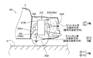
本発明の第2実施形態によるいわゆるRR駆動方式の車両201は、図9~図11に示すように、車両201を駆動させるためのエンジン210が収容されるエンジンルーム202(収容部の一例)を備えている。エンジンルーム202は、車内3の後方(X2方向)に形成されている。また、エンジンルーム202の後部(X2方向側の部分)には、開口部202fが形成されている。開口部202fは、車両201における幅方向の略中央に格子状に形成されている。
また、図11に示すように、エンジンルーム202のY1方向側の側部および底部(X2方向)には、開口部202lが形成されているとともに、エンジンルーム202のY2方向側の側部および底部には、開口部202mが形成されている。これら開口部202f、202lおよび202mは、エンジンルーム202と車外とを連通している。
ここで、第2実施形態では、図9~図11に示すように、車両201には、エンジン210の騒音を低減させるためのエンジン騒音低減装置200が搭載されている。エンジン騒音低減装置200は、エンジン210から放射される騒音と逆位相のキャンセル音を発生させる3個(複数)のスピーカ230(後側スピーカ230a、前側スピーカ230b、前側スピーカ230c)を含んでいる。なお、3個のスピーカ230は、エンジンルーム202内に配置されている。
3個のスピーカ230は、各々、エンジン210の外表面210bから離れる方向に向かってキャンセル音を発生させるように構成されている。さらに、3個のスピーカ230は、エンジンルーム202と車外とを連通する開口部202f、202lおよび202mに向かってキャンセル音を放射するように配置されている。なお、3個のスピーカ230のうち、後側スピーカ230aは開口部202fに対応しており、前側スピーカ230bは開口部202lに対応しており、前側スピーカ230cは開口部202mに対応している。
具体的には、後側スピーカ230aは、エンジン210の後方(X2方向)で、かつ、エンジン210の外表面210b近傍に配置されている。さらに、後側スピーカ230aは、エンジンルーム202の後方に形成された開口部202f近傍に配置されている。そして、後側スピーカ230aは、開口部202fに向かって、前方にキャンセル音を発生させるように構成されている。
前側スピーカ230bは、エンジン210の幅方向の一方側(Y1方向側)で、かつ、エンジン210の外表面210b近傍に配置されている。さらに、前側スピーカ230bは、エンジンルーム202の前方かつ下方に形成された開口部202l近傍に配置されている。そして、前側スピーカ230bは、開口部202lに向かって、下方、かつ、Y1方向にキャンセル音を発生させるように構成されている。
前側スピーカ230cは、エンジン210の幅方向の他方側(Y2方向側)で、かつ、エンジン210の外表面210b近傍に配置されている。さらに、前側スピーカ230cは、エンジンルーム202の前方かつ下方に形成された開口部202m近傍に配置されている。そして、前側スピーカ230cは、エンジンルーム202の開口部202mに向かって、下方、かつ、Y2方向にキャンセル音を発生させるように構成されている。なお、第2実施形態のその他の構成は、第1実施形態の構成と同様である。
(第2実施形態の効果)
第2実施形態では、以下のような効果を得ることができる。
第2実施形態では、以下のような効果を得ることができる。
第2実施形態では、上記のように、スピーカ230を、エンジン210から放射される騒音の放射方向に沿った方向で、かつ、エンジンルーム202に設けられた開口部202fおよび202gに向かってキャンセル音を放射するように配置する。これにより、第1実施形態と同様に、車外に漏れ出る騒音を十分に低減することができる。
また、第2実施形態では、後側スピーカ230a、前側スピーカ230bおよび前側スピーカ230cを、それぞれ、エンジンルーム202の開口部202f、202lおよび202mに向かってキャンセル音を放射するように配置する。これにより、エンジンルーム202の開口部202fから車外に漏れ出る騒音を、開口部202fに向かって放射される、後側スピーカ230aからのキャンセル音により効果的に低減することができる。また、エンジンルーム202の開口部202lおよび202mから車外に漏れ出る騒音を、開口部202lおよび202mに向かってそれぞれ放射される、前側スピーカ230bからのキャンセル音および前側スピーカ230cからのキャンセル音により効果的に低減することができる。したがって、車外に漏れ出る騒音を十分に低減することができる。なお、第2実施形態のその他の効果は、第1実施形態の効果と同様である。
[変形例]
今回開示された実施形態は、全ての点で例示であり制限的なものではないと考えられるべきである。本発明の範囲は上記実施形態の説明ではなく特許請求の範囲によって示され、さらに特許請求の範囲と均等の意味および範囲内での全ての変更(変形例)が含まれる。
今回開示された実施形態は、全ての点で例示であり制限的なものではないと考えられるべきである。本発明の範囲は上記実施形態の説明ではなく特許請求の範囲によって示され、さらに特許請求の範囲と均等の意味および範囲内での全ての変更(変形例)が含まれる。
たとえば、上記第1および第2実施形態では、エンジン騒音低減装置100(200、車両動力源騒音低減装置)により、直列4気筒のエンジン10(210、車両動力源)の騒音を低減させる例を示したが、本発明はこれに限られない。本発明では、車両動力源騒音低減装置を、直列4気筒型以外の多気筒型エンジンやV型多気筒型エンジンなどの騒音を低減させるために用いてもよい。また、車両動力源騒音低減装置を、騒音を低減する必要のある自動車用以外のたとえば設備機器などに搭載されたエンジンの騒音を低減させるために用いてもよい。また、車両動力源はエンジンに限られず、たとえば、モータであってもよい。さらに、車両動力源は1個に限られず、2個以上の車両動力源の騒音を低減するように車両動力源騒音低減装置を用いてもよい。たとえば、エンジンとモータとの両方が搭載された車両において、エンジンとモータとの両方の騒音を低減するように車両動力源騒音低減装置を用いてもよい。
また、上記第1または第2実施形態の構成に加えて、車両動力源騒音低減装置に、車両動力源から放射される騒音を集音する集音器をさらに設けてもよい。そして、車両動力源騒音低減装置を、集音器において集音した騒音と基準の騒音(たとえば、初期の車両動力源の騒音)とのずれ量がずれ閾値を超えた場合に、ずれを補正するように構成してもよい。この場合、マイクは、車両動力源からの騒音を優先的に集音可能であるのが好ましい。
また、上記第1または第2実施形態における3個のスピーカ30(230)として、異なる指向性または異なる周波数特性を有する異なるスピーカを用いてもよい。
また、上記第1実施形態では、記憶部43に、0%より大きく100%以下のエンジン負荷率と、0rpmより大きく6000rpm(最大回転数)以下のエンジン回転数とに対応するキャンセル音データ43a~43cがそれぞれ記憶されている例を示したが、本発明はこれに限られない。本発明では、車両動力源の性能によっては最大回転数の値を変更してもよい。また、負荷率および回転数以外のパラメータ(たとえば、スロットル開度など)に応じて、キャンセル音データを記憶してもよい。
また、上記第1実施形態では、記憶部43において、キャンセル音データ43a~43cが、各々、エンジン負荷率に関しては5%刻み、エンジン回転数に関しては50rpm刻みで記憶されている例を示したが、本発明はこれに限られない。本発明では、キャンセル音データの数は、所望の騒音低減の度合いなどに応じて、適宜変更してもよい。
また、上記第1および第2実施形態では、3個のスピーカ30(230)を、エンジンルーム2(202、収容部)内のエンジン10(210)の外表面10b(210b)近傍に配置した例を示したが、本発明はこれに限られない。本発明では、スピーカは収容部内に配置されていればよく、スピーカをエンジンの外表面から離れた位置に配置してもよい。
また、上記第1および第2実施形態では、3個のスピーカ30(230)を用いた例を示したが、本発明はこれに限られない。本発明では、スピーカは1個、2個または4個以上であってもよい。
また、上記第1実施形態では、前側スピーカ30aを開口部2fに対応させ、後側スピーカ30bおよび30cを開口部2gに対応させた例を示した。また、上記第2実施形態では、後側スピーカ230aを開口部202fに対応させ、前側スピーカ230bを開口部202lに対応させ、前側スピーカ230bを開口部202mに対応させた例を示したが、本発明はこれに限られない。本発明では、1個のスピーカを複数の開口部に向かってキャンセル音を放射するように構成することによって、1個のスピーカを複数の開口部に対応させてもよい。
また、上記第1実施形態では、1個の大きな開口部2gに対して、2個のスピーカ(後側スピーカ30bおよび後側スピーカ30c)を用いた例を示したが、本発明はこれに限られない。本発明では、大きな開口部に対して、1個または3個以上のスピーカを用いてもよい。なお、大きな開口部に対して指向性の広い(指向角度の大きい)スピーカを用いることによって、スピーカの数を減少させることが可能である。
また、上記第1および第2実施形態では、複数のスピーカ30(230)として、指向性のあるスピーカを用いた例を示したが、本発明はこれに限られない。本発明では、開口部に向かってキャンセル音を放射可能であれば、スピーカは無指向性のスピーカであってもよい。なお、開口部以外にキャンセル音が向かうのを抑制するために、指向性を有するスピーカを用いる方が好ましい。
また、上記第1実施形態では、いわゆるFF駆動方式の車両1を示し、上記第2実施形態では、いわゆるRR駆動方式の車両201を示したが、本発明はこれに限られない。たとえば、車両は、いわゆるFR駆動方式でもよい。この場合、車両動力源騒音低減装置のスピーカは、上記第1実施形態と同様に、車両の室内の前方に形成された収容部内に車両動力源と共に配置される。また、たとえば、車両は、いわゆるMR駆動方式でもよい。この場合、車両動力源騒音低減装置のスピーカは、上記第2実施形態と同様に、車両の室内の後方に形成された収容部内に車両動力源と共に配置される。
また、上記第1実施形態では、スピーカ30がキャンセル音を放射する、エンジンルーム2と車外とを連通する開口部として、前方に形成された開口部2fと、側方と、後方および下方とに亘って形成された開口部2gとを例として示した。また、上記第2実施形態では、スピーカ230がキャンセル音を放射する開口部として、後方に形成された開口部202fと、側方と下方とに亘って形成された開口部202lおよび202mとを例として示したが、本発明はこれに限られない。本発明では、スピーカがキャンセル音を放射する開口部は、収容部と車外とを連通する開口部であれば、形成位置は特に限定されない。たとえば、サイドパネルとボンネットとの間に収容部と車外とを連通する開口部がある場合には、サイドパネルとボンネットとの間の開口部に向かって、スピーカがキャンセル音を放射するように車両動力源騒音低減装置を構成してもよい。
また、上記第1または第2実施形態の構成に加えて、開口部に向かってキャンセル音を放射しないスピーカを新たに設けてもよい。この場合、車両動力源から放射される騒音をキャンセル音により確実に低減させるために、新たに設けるスピーカは、車両動力源の外表面近傍に設けられるのが好ましい。
1、201 車両
2、202 エンジンルーム(収容部)
2f、202f 開口部(第1開口部)
2g、202l、202m 開口部(第2開口部)
2h、2j 開口部分(第1開口部分)
2i、2k 開口部分(第2開口部分)
5c ステアリングロッド
8 サスペンション
9 フロントグリル
10 エンジン(車両動力源)
10a エンジン本体
10b 外表面
12 インテークマニホールド(吸気合流管)
13 エキゾーストマニホールド(排気合流管)
14 排気ダクト
30、230 スピーカ
30a 前側スピーカ(第1スピーカ)
30b 後側スピーカ(第2スピーカ、一方スピーカ)
30c 後側スピーカ(第2スピーカ、他方スピーカ)
34 振動板(音波発生部)
100、200 エンジン騒音低減装置(車両動力源騒音低減装置)
230a 後側スピーカ(第1スピーカ)
230b、230c 前側スピーカ(第2スピーカ)
2、202 エンジンルーム(収容部)
2f、202f 開口部(第1開口部)
2g、202l、202m 開口部(第2開口部)
2h、2j 開口部分(第1開口部分)
2i、2k 開口部分(第2開口部分)
5c ステアリングロッド
8 サスペンション
9 フロントグリル
10 エンジン(車両動力源)
10a エンジン本体
10b 外表面
12 インテークマニホールド(吸気合流管)
13 エキゾーストマニホールド(排気合流管)
14 排気ダクト
30、230 スピーカ
30a 前側スピーカ(第1スピーカ)
30b 後側スピーカ(第2スピーカ、一方スピーカ)
30c 後側スピーカ(第2スピーカ、他方スピーカ)
34 振動板(音波発生部)
100、200 エンジン騒音低減装置(車両動力源騒音低減装置)
230a 後側スピーカ(第1スピーカ)
230b、230c 前側スピーカ(第2スピーカ)
Claims (10)
- 車両を駆動させるための車両動力源が収容される収容部内に配置され、前記車両動力源から放射される騒音を低減する、前記騒音とは逆位相のキャンセル音を発生させるスピーカを備え、
前記スピーカは、前記車両動力源から放射される前記騒音の放射方向に沿った方向で、かつ、前記収容部と車外とを連通する開口部に向かって前記キャンセル音を放射するように配置されている、車両動力源騒音低減装置。 - 前記スピーカは、複数設けられており、
複数の前記スピーカは、各々、前記収容部に設けられた複数の前記開口部の各々に対応付けられており、対応する前記開口部に向かって前記キャンセル音を放射するように配置されている、請求項1に記載の車両動力源騒音低減装置。 - 前記収容部の前記開口部は、前記収容部の前記車両の室内とは反対側に形成された第1開口部と、前記収容部の少なくとも底部に形成された第2開口部とを含み、
複数の前記スピーカは、前記第1開口部に向かって前記キャンセル音を放射するように配置された第1スピーカと、前記第2開口部に向かって前記キャンセル音を放射するように配置された第2スピーカとを含む、請求項2に記載の車両動力源騒音低減装置。 - 前記第2開口部は、前記収容部の前記底部と側部とに亘って形成されており、
前記第2スピーカは、前記第2開口部のうち、前記側部の一方側部および前記一方側部側の前記底部に亘って形成された第1開口部分に向かって前記キャンセル音を放射するように配置された一方スピーカと、前記第2開口部のうち、前記側部の他方側部および前記他方側部側の前記底部に亘って形成された第2開口部分に向かって前記キャンセル音を放射するように配置された他方スピーカとを有する、請求項3に記載の車両動力源騒音低減装置。 - 前記スピーカは、前記開口部の近傍に配置されている、請求項1~4のいずれか1項に記載の車両動力源騒音低減装置。
- 前記スピーカは、警告音を発生させる前記車両のホーンを兼ねる、請求項1~5のいずれか1項に記載の車両動力源騒音低減装置。
- 前記車両動力源は、エンジン本体と、前記エンジン本体に接続される吸気分配管および排気合流管とを有するエンジンを含む、請求項1~6のいずれか1項に記載の車両動力源騒音低減装置。
- 前記車両動力源は、エンジン本体と、前記エンジン本体に接続される吸気分配管および排気合流管とを有するエンジンを含み、
前記第1開口部は、前記車両のフロントグリルの開口部であり、前記第2開口部は、前記車両のステアリングロッドまたはサスペンションのための開口部、前記排気合流管に接続される排気ダクトのための開口部、および、前記収容部内の空気を放出するための開口部の少なくともいずれかである、請求項3または4に記載の車両動力源騒音低減装置。 - 前記スピーカは、前記車両動力源の外表面近傍に配置されている、請求項1~8のいずれか1項に記載の車両動力源騒音低減装置。
- 前記スピーカの前記キャンセル音を発生させる音波発生部は、前記車両動力源の前記外表面から、前記騒音の最大周波数に対応する最小波長の1/4の距離未満の範囲内に配置されている、請求項9に記載の車両動力源騒音低減装置。
Applications Claiming Priority (2)
| Application Number | Priority Date | Filing Date | Title |
|---|---|---|---|
| JP2017074670A JP2018180059A (ja) | 2017-04-04 | 2017-04-04 | 車両動力源騒音低減装置 |
| JP2017-074670 | 2017-04-04 |
Publications (1)
| Publication Number | Publication Date |
|---|---|
| WO2018186069A1 true WO2018186069A1 (ja) | 2018-10-11 |
Family
ID=63712860
Family Applications (1)
| Application Number | Title | Priority Date | Filing Date |
|---|---|---|---|
| PCT/JP2018/007788 Ceased WO2018186069A1 (ja) | 2017-04-04 | 2018-03-01 | 車両動力源騒音低減装置 |
Country Status (2)
| Country | Link |
|---|---|
| JP (1) | JP2018180059A (ja) |
| WO (1) | WO2018186069A1 (ja) |
Citations (4)
| Publication number | Priority date | Publication date | Assignee | Title |
|---|---|---|---|---|
| JPH02149197A (ja) * | 1988-11-30 | 1990-06-07 | Isuzu Motors Ltd | 車外騒音低減装置 |
| JPH07152385A (ja) * | 1993-11-26 | 1995-06-16 | Nippon Soken Inc | 騒音制御装置 |
| JP2012046059A (ja) * | 2010-08-26 | 2012-03-08 | Denso Corp | 車両接近報知装置 |
| US20120070012A1 (en) * | 2010-09-20 | 2012-03-22 | Hitachi, Ltd | Noise reduction system for an electrically poered automotive vehicle |
-
2017
- 2017-04-04 JP JP2017074670A patent/JP2018180059A/ja active Pending
-
2018
- 2018-03-01 WO PCT/JP2018/007788 patent/WO2018186069A1/ja not_active Ceased
Patent Citations (4)
| Publication number | Priority date | Publication date | Assignee | Title |
|---|---|---|---|---|
| JPH02149197A (ja) * | 1988-11-30 | 1990-06-07 | Isuzu Motors Ltd | 車外騒音低減装置 |
| JPH07152385A (ja) * | 1993-11-26 | 1995-06-16 | Nippon Soken Inc | 騒音制御装置 |
| JP2012046059A (ja) * | 2010-08-26 | 2012-03-08 | Denso Corp | 車両接近報知装置 |
| US20120070012A1 (en) * | 2010-09-20 | 2012-03-22 | Hitachi, Ltd | Noise reduction system for an electrically poered automotive vehicle |
Also Published As
| Publication number | Publication date |
|---|---|
| JP2018180059A (ja) | 2018-11-15 |
Similar Documents
| Publication | Publication Date | Title |
|---|---|---|
| EP0878001B1 (en) | System and method for reducing engine noise | |
| EP3537430B1 (en) | Method and apparatus for a low cost, acoustic tire cavity resonance canellation | |
| KR20220061858A (ko) | 엔진 소음 상쇄를 위한 가상 위치 노이즈 신호 추정 | |
| US20080144852A1 (en) | Multi-chamber noise control system | |
| EP3157001A1 (en) | Engine order and road noise control | |
| US10427600B2 (en) | Motor vehicle sound generator system | |
| US20230145186A1 (en) | Battery electric vehicle active sound and vibration enhancement systems | |
| EP2211562A1 (en) | Loudspeaker installation | |
| JP5926158B2 (ja) | 能動型消音装置 | |
| WO2018186070A1 (ja) | 車両動力源騒音低減装置 | |
| JP2020062958A (ja) | 車両接近通報装置 | |
| Cheer et al. | Sound field control in the automotive environment | |
| US8184820B2 (en) | Indirect acoustic transfer control of noise | |
| JPWO2017038442A1 (ja) | 移動体用スピーカシステム | |
| JP2018180059A (ja) | 車両動力源騒音低減装置 | |
| WO2011111177A1 (ja) | 擬似音発生装置及び擬似音発生方法 | |
| US12342114B2 (en) | Motor vehicle with sound system | |
| JP2018075895A (ja) | 車両用警報音発生装置 | |
| US20210256953A1 (en) | Concurrent fxlms system with common reference and error signals | |
| WO2023086310A1 (en) | Active sound and vibration enhancement systems for battery electric vehicle | |
| WO2023086308A1 (en) | Battery electric vehicle active sound and vibration enhancement systems | |
| JP2516687B2 (ja) | 内燃機関の吸気装置 | |
| JP3146023B2 (ja) | エンジン騒音制御装置 | |
| US20050000743A1 (en) | Herschel-Quincke tube arrangements for motor vehicles | |
| Lennström et al. | Determination of radiated sound power from an electric rear axle drive in-situ and its contribution to interior noise |
Legal Events
| Date | Code | Title | Description |
|---|---|---|---|
| 121 | Ep: the epo has been informed by wipo that ep was designated in this application |
Ref document number: 18780898 Country of ref document: EP Kind code of ref document: A1 |
|
| NENP | Non-entry into the national phase |
Ref country code: DE |
|
| 122 | Ep: pct application non-entry in european phase |
Ref document number: 18780898 Country of ref document: EP Kind code of ref document: A1 |