WO2018185980A1 - Rear shell structure and seat unit - Google Patents
Rear shell structure and seat unit Download PDFInfo
- Publication number
- WO2018185980A1 WO2018185980A1 PCT/JP2017/045276 JP2017045276W WO2018185980A1 WO 2018185980 A1 WO2018185980 A1 WO 2018185980A1 JP 2017045276 W JP2017045276 W JP 2017045276W WO 2018185980 A1 WO2018185980 A1 WO 2018185980A1
- Authority
- WO
- WIPO (PCT)
- Prior art keywords
- seat
- shell
- shell structure
- region
- back shell
- Prior art date
Links
Images


Classifications
-
- B—PERFORMING OPERATIONS; TRANSPORTING
- B64—AIRCRAFT; AVIATION; COSMONAUTICS
- B64D—EQUIPMENT FOR FITTING IN OR TO AIRCRAFT; FLIGHT SUITS; PARACHUTES; ARRANGEMENTS OR MOUNTING OF POWER PLANTS OR PROPULSION TRANSMISSIONS IN AIRCRAFT
- B64D11/00—Passenger or crew accommodation; Flight-deck installations not otherwise provided for
- B64D11/06—Arrangements of seats, or adaptations or details specially adapted for aircraft seats
- B64D11/0649—Seats characterised by special features for reducing weight
-
- B—PERFORMING OPERATIONS; TRANSPORTING
- B64—AIRCRAFT; AVIATION; COSMONAUTICS
- B64D—EQUIPMENT FOR FITTING IN OR TO AIRCRAFT; FLIGHT SUITS; PARACHUTES; ARRANGEMENTS OR MOUNTING OF POWER PLANTS OR PROPULSION TRANSMISSIONS IN AIRCRAFT
- B64D11/00—Passenger or crew accommodation; Flight-deck installations not otherwise provided for
- B64D11/06—Arrangements of seats, or adaptations or details specially adapted for aircraft seats
- B64D11/0648—Lower frame constructions
-
- B—PERFORMING OPERATIONS; TRANSPORTING
- B64—AIRCRAFT; AVIATION; COSMONAUTICS
- B64D—EQUIPMENT FOR FITTING IN OR TO AIRCRAFT; FLIGHT SUITS; PARACHUTES; ARRANGEMENTS OR MOUNTING OF POWER PLANTS OR PROPULSION TRANSMISSIONS IN AIRCRAFT
- B64D11/00—Passenger or crew accommodation; Flight-deck installations not otherwise provided for
- B64D11/0015—Arrangements for entertainment or communications, e.g. radio, television
-
- Y—GENERAL TAGGING OF NEW TECHNOLOGICAL DEVELOPMENTS; GENERAL TAGGING OF CROSS-SECTIONAL TECHNOLOGIES SPANNING OVER SEVERAL SECTIONS OF THE IPC; TECHNICAL SUBJECTS COVERED BY FORMER USPC CROSS-REFERENCE ART COLLECTIONS [XRACs] AND DIGESTS
- Y02—TECHNOLOGIES OR APPLICATIONS FOR MITIGATION OR ADAPTATION AGAINST CLIMATE CHANGE
- Y02T—CLIMATE CHANGE MITIGATION TECHNOLOGIES RELATED TO TRANSPORTATION
- Y02T50/00—Aeronautics or air transport
- Y02T50/40—Weight reduction
Definitions
- the present invention relates to a back shell structure and a seat unit using the same.
- Patent Document 1 describes a seat assembly including an integrated composite structure frame and a comfort frame assembly connected to the composite structure frame and provided for each passenger.
- This composite structure frame is composed of a support leg connected to the aircraft body, a back support element connected to the support leg, and an upper back cross beam and a lower back cross beam connected to the back support element. Has been.
- An opening is provided between the upper back cross beam and the lower back cross beam to accommodate a tray table for use by passengers behind.
- one of the representative back shell structures and seat units of the present invention is a back shell structure covering the back of a seat, comprising a front member and a rear member, A part of the back shell structure is provided with a region in which a space reinforcing member is provided between the front member and the rear member (hereinafter referred to as “reinforcing region”).
- the front member and the rear member are directly joined.
- the front perspective view of a common seat unit The front perspective view of the shell structure containing the back surface shell structure concerning a 1st embodiment.
- the front perspective view of a seat The front perspective view of a seat unit.
- the rear perspective view of a seat base Sectional drawing of the shell structure which concerns on 1st Embodiment. Sectional drawing of the shell structure which concerns on 1st Embodiment (modification 1). Sectional drawing of the shell structure which concerns on 1st Embodiment (modification 2).
- the expanded sectional view of the taper part of the shell structure concerning a 1st embodiment modification 3). Sectional drawing of the shell structure which concerns on 2nd Embodiment.
- the rear perspective view of the shell structure concerning a 3rd embodiment.
- the rear perspective view of the seat unit concerning a 4th embodiment.
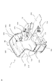
- FIG. 1 is a perspective view of a business class or first class seat unit disposed in an aircraft cabin as viewed from the front.
- the seat unit 1 has a structure in which the seat 10 is surrounded by a shell 20, and in this figure, equipment used by passengers (such as a reading light 360) is also depicted.
- the seat 10 includes a lower seat 110, an upper seat 120, a headrest 130, and a legrest 140.
- the lower seat 110 is also called a seating portion
- the upper seat 120 is also called a backrest portion.
- a seat belt 150 is attached to the seat.
- the shell 20 includes a right shell 210 on the right side of the seat 10, a rear shell 220 on the back of the seat 10, and a left shell 230 on the left side of the seat 10.
- the seat unit 1 further has various equipment.
- a right armrest 310 is provided on the right side of the seat 10.
- a left armrest 320 is provided on the left side of the seat 10.
- the left armrest 320 is provided with an openable storage box 330.
- the ottoman 340 is disposed in front of the left armrest portion 320.
- an electrical equipment jack 350 and a reading lamp 360 are disposed.
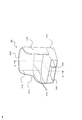
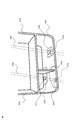
- FIG. 2 is a perspective view of the shell structure including the back shell structure according to the first embodiment as viewed obliquely from the front.
- the shell 20 is composed of a seat base 240 which is a lower structure of the seat unit and an upper shell existing thereon.
- the upper shell includes a right shell 210, a back shell 220 that covers the entire back surface, and a left shell 230.
- the seat base 240 which is the lower structure of the seat unit, is formed into a hollow box shape using integrally formed members.
- the integrally formed member specifically includes a thermoplastic resin such as polyetherimide and polyetherketone ketone, a thermosetting resin capable of appropriately controlling flammability, carbon graphite fiber, and glass.
- the upper shell is also formed of a similar composite member.
- Such an integrally formed composite member can form a strong three-dimensional shape without using connecting parts such as bolts and nuts. Moreover, since it is formed of the composite material as described above, it is possible to significantly reduce the number of places where rust prevention treatment is performed, compared to existing metal structural members.
- the hollow box structure is a so-called monocoque structure. Therefore, the seat base 240 can support the load of the seat, the passenger, and the equipment (such as the reading lamp 360) used by the passenger.
- the hollow region 242 of the seat base 240 is rectangular when viewed from the front of the seat, but may be a quadrilateral such as a trapezoid. Further, the thickness of the members constituting the seat base 240, that is, the seat lower structure is about 10 mm to 15 mm.
- a seat base 240 there is no concept of a columnar support that supports the foot of one seat, that is, a leg portion, so that there is no position restriction depending on the position of the seat track on the aircraft side. Further, a common structure can be adopted for seats of various sizes and shapes regardless of the shape of the upper structure of the seat. Furthermore, the mounting of electrical equipment and the layout of the wiring accompanying this are not restricted by the position of the leg, so that the degree of freedom in design can be expanded and shared.
- a partition member 250 can be disposed in the hollow region 242. Since the seat base 240 has a hollow monocoque structure, the partition member 250 (sometimes referred to as a partition plate) does not need to support the load of passengers or the like, and can move freely within the hollow region 242.
- a back surface side shell 220 that is a back surface shell structure covering the back portion of the seat is provided with a space reinforcing member below the front surface member and the rear surface member constituting the shell.
- a region where the space reinforcing member is provided is called a reinforcing region.
- a honeycomb structure will be described as an example of the space reinforcing member.
- Above the rear shell 220 there is no honeycomb structure between the front member and the rear member, and the front member and the rear member are directly joined. That is, the upper side of the back side shell 220 is a region other than the reinforcing region.
- the material of the front member and the rear member is, for example, a composite fiber made of resin and fiber.
- the material of the honeycomb structure is, for example, a composite fiber made of nonflammable paper and phenol resin.
- the structural branch line 226 is dotted in the center of the back side shell 220, which has a honeycomb structure between the front member and the rear member constituting the shell.
- the boundary between the region (ie, the reinforcing region) and the region not having the honeycomb structure (ie, the region other than the reinforcing region) is shown.
- a shell boundary line 215 is drawn between the right shell 210 and the back shell 220 for convenience.
- the right shell 210 may have a honeycomb structure between the front member and the rear member constituting the shell in the region below the structural branch line 226.
- the region having the honeycomb structure may be appropriately changed regardless of the structure branch line 226. If not necessary, the right shell 210 may not have a honeycomb structure. In the region not having the honeycomb structure, it is desirable that the front member and the rear member constituting the shell are directly joined.
- the left shell 230 has the same configuration as the right shell 210 described above.
- the front of the left shell 230 does not reach the front of the seat base 240, but may be arranged up to the front of the seat base 240 similarly to the right shell 210.
- FIG. 3 is a perspective view of an example of the seat used in the first embodiment when viewed obliquely from the front.
- the seat 10 is a lower seat 110 on which a passenger sits, an upper seat 120 on which the back is placed, a pillow-like portion on the upper portion of the backrest, a headrest 130 on which the head rests and rests the neck, and a calf on which the leg is placed
- a legrest 140 that reduces fatigue such as the above is provided.
- the seat reclining mechanism 180 is a mechanism that tilts the upper seat 120 backward.
- the foot reclining mechanism 190 is a mechanism that rotates the legrest 140 so as to lift up near the surface of the lower seat 110.
- FIG. 4 is a perspective view of the seat unit adopting the back shell structure according to the first embodiment as viewed obliquely from the front.
- the seat unit 1 has a configuration in which the seat 10 described with reference to FIG. 3 is placed on the shell 20 described with reference to FIG. 2.
- a storage box 330 serving as a console and a rear seat leg space is disposed between the seat 10 and the right shell 210.
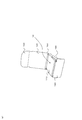
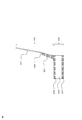
- FIG. 5 is a perspective view of the lower structure (seat base) of the seat unit as viewed obliquely from the rear.
- the shell 20 omits the back side shell 220 for the sake of convenience in explaining a seat track described later, and only the right side shell 210 and the left side shell 230 are shown.
- the first seat track 282 and the second seat track 284 constitute a pair of seat tracks, and extend in the longitudinal direction on the floor of the aircraft body.
- the seat unit 1 is attached to the aircraft body by fixing the bottom of the seat unit 1 (in FIG. 5, the bottom of the seat base 240) to a pair of seat tracks. And passing a predetermined dynamic load test is necessary for ensuring the safety of passengers.
- the seat base 240 is disposed slightly to the left with respect to the longitudinal direction of the aircraft body. For this reason, the seat base 240 does not face the first seat track 282 and the second seat track 284, and faces slightly to the left.
- the seat base 240 is fixed to three attachments for attachment to the aircraft body via three attachment blocks. Since the seat base 240 has a monocoque structure, a mounting block is provided at the bottom of the seat base 240 and is used to reinforce the connection between the fixture and the seat base 240.
- the mounting block is preferably made of metal, but the material is not limited as long as it is a reinforcing block.
- a first mounting block 262 is disposed in front of the bottom of the seat base 240 and a second mounting block 264 is disposed behind the seat base 240 in order to attach the seat base 240 to the aircraft body at three locations. ing.
- the third mounting block 266 is disposed on the right side.
- the mounting tool for the seat track is arranged (the mounting tool is indicated by a solid line). That is, the first attachment 272 is disposed below the first attachment block 262 and attached to the first seat track 282.
- the second fixture 274 is disposed below the second fixture block 264 and is attached to the first seat track 282 at a point spaced from the first fixture 272.
- the third fixture 276 is disposed below the third fixture block 266 and is a second seat track 284 between the first fixture 272 and the second fixture 274. It is attached to the corresponding part. Desirably, it is attached between the first attachment 272 and the second attachment 274 at substantially the center of the corresponding portion.
- FIG. 6 is a cross-sectional view of the shell structure according to the first embodiment taken along line AA in FIG.
- the seat base 240 is composed of a bottom portion 241 and an upper portion 243 that cover the upper and lower sides of the hollow region 242, and the bottom portion 241 and the upper portion 243 are shown to be a honeycomb structure.
- the rear shell 220 which is the rear shell structure has a honeycomb structure in the lower portion 221 below the structural branch line 226, but has a honeycomb structure in the upper portion 227 above the structural branch line 226.
- a structure without a body is shown.
- the structural branch line 226 is approximately the center of the back side shell 220. And, it has such a cross-sectional structure over the entire lateral width of the back side shell 220.
- FIG. 7 is a cross-sectional view of Modification 1 of the first embodiment shown in FIG.
- the difference from the case of FIG. 6 is that the position of the structural branch line 226a is high, which is about a quarter from the top of the back side shell 220a.
- the lower part 221a corresponds to the entire passenger's back, waist to shoulder, and the upper part 227a corresponds to the passenger's head.
- FIG. 8 is a cross-sectional view of Modification 2 of the first embodiment shown in FIG.
- the difference from FIG. 6 is that the position of the structural branch line 226b is low and is about a quarter from the bottom of the back-side shell 220b. Therefore, the lower part 221b corresponds to the passenger's waist, and the upper part 227b corresponds to the passenger's chest to the head.
- the region having the honeycomb structure can be appropriately selected based on the strength required for the shell, the cost required for manufacturing, and the like.
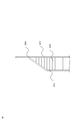
- FIG. 9 is an enlarged cross-sectional view of a region (hereinafter referred to as a “tapered portion”) in the vicinity of the front member and the rear member constituting the shell of the back shell structure according to the first embodiment.
- 6 is an enlarged view of the vicinity of the structural branch line 226 of FIG.
- the front surface member 222 and the rear surface member 223 constituting the shell sandwich the honeycomb structure 224 below the back surface side shell 220.
- the space between the front member 222 and the rear member 223 becomes narrower and becomes tapered. That is, the distance between the front member 222 and the rear member 223 constituting the reinforcing region is gradually reduced toward the region other than the reinforcing region.
- the front member 222 and the rear member 223 are directly joined without the honeycomb structure 224 interposed therebetween.
- the honeycomb structure 224 is filled up to the tapered portion.
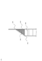
- FIG. 10 is an enlarged cross-sectional view of a modified example of the tapered portion shown in FIG.
- the difference from FIG. 9 is that the honeycomb structure 224 is not filled up to the tapered portion but is filled with the sponge member 225. That is, a sponge is provided between the front member and the rear member between the region where the honeycomb structure is provided between the front member and the rear member and the region where the front member and the rear member are directly joined. It has the area
- a portion having a honeycomb structure is provided below the back shell structure between the front member and the rear member constituting the shell, so that the entire upper shell has a strong impact at the bottom.
- the elastic displacement due to the impact can be quickly returned to the original state in the upper part. Thereby, the intensity
- the lower side of the back shell structure is in the direction of the seat track, that is, the back shell structure.
- the right shell 210 and the left shell 230 also have the same structure as above and below the back shell 220, and the back shell structure is integrally formed with the back shell 220, the right shell 210, and the left shell 230.
- the back shell structure is integrally formed with the back shell 220, the right shell 210, and the left shell 230.
- FIG. 11 is a cross-sectional view of a shell structure according to the second embodiment.
- positioned the display 370 for backseats in the upper part 227c of the back side shell 220c is the same as 1st Embodiment.
- the back side shell 220c in the partial region 227c of the upper part of the back side shell 220c, the back side shell 220c is inflated forward and a recess is provided in the rear. And the display 370 is arrange
- the passengers in the rear seat can see the display in a fixed position because the rear shell structure is not moved by the reclining operation. it can. That is, the passenger in the rear seat does not know whether the front seat is in a normal state or a reclining state. That is, for the passenger in the front seat, the back side shell covers and conceals his own work, so that the passenger behind him does not notice his work.
- a portion having a honeycomb structure is provided below the back shell structure between the front member and the rear member constituting the shell. Even when the display is placed on the back shell structure, sufficient strength can be maintained.
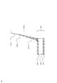
- FIG. 12 shows the shell 20 obtained by integrally molding the seat base 240 and the upper shell described in the first embodiment.
- the points are the same as in the first embodiment except that the seat base 240 and the upper shell are integrally molded.
- the seat base 240 and the upper shell are integrally molded together to realize a monocoque structure.
- the composite material used for the integrally molded member is the same as in the first embodiment.
- the third embodiment it has the same effect as the first embodiment, and further, since the seat base and the upper shell are integrated, the strength of the entire seat is improved, and at the time of production Assembly can also be improved. Moreover, it has the effect that an attachment operation can be simplified.
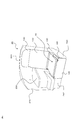
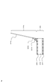
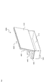
- FIG. 13 is a perspective view of the seat unit according to the fourth embodiment as viewed obliquely from the rear.
- the seat unit 400 is for an economy class arranged in an aircraft cabin.
- the seat unit 400 includes a seat 410, a seat base 500, and a back side shell 600.
- the seat 410 includes an upper seat 420, a lower seat 430, and a seat belt 440.
- the seat base 500 is a hollow box-type seat lower structure that is integrally molded as in the first embodiment.
- the seat unit 400 includes a seat 410 for four people and a seat base 500. That is, there is one hollow region 510.
- the back shell 600 covers the entire back part, which is the back part of the seat 410 for four persons.
- the cross-sectional structure and material of the back side shell 600 are the same as those in the first embodiment.
- the back side shell 600 and the seat base 500 may be integrally formed.
- the object of the present invention is not limited to the aircraft, but can be applied to various mobile seats other than aircraft.
- Various modifications are included.
- trains, long-distance buses, and other types of vehicles and vehicles, such as water transportation, including passenger ships, ferries, and hovercraft, may be used as appropriate.
Abstract
The purpose of the present invention is to provide a rear shell structure (220) of a form covering the back portion that can be attached to a bottom structure (240) of a seat not having support legs. In one representative embodiment of this rear shell structure (220) which covers the back portion of the seat, one of the rear shell structure (220) and the seat unit is formed from a front member (222) and a rear member (223). In one area of the rear shell structure (220), a region (below, referred to as the "reinforcing region") is provided in which a spatial reinforcing member (224) is provided between the front member (222) and the rear member (223), and, outside of the reinforcing region, a front member (222) and the rear member (223) are bonded directly together. Furthermore, the front member (222) and the rear member (223) are formed from a composite member. Further, the spatial reinforcing member (224) has a honeycomb structure.
Description
本発明は、背面シェル構造体及びこれを用いた座席ユニットに関する。
The present invention relates to a back shell structure and a seat unit using the same.
近年の航空機設計においては、航空機構造の軽量化や座席ユニットをはじめとする機内設備の設置の簡便化が求められている。航空機構造の軽量化が達成できれば、その分、航空機が運べる乗客数を増加させることもでき、航空機の潜在的収益性を増大させることができる。
In recent aircraft design, it is required to reduce the weight of the aircraft structure and simplify the installation of in-flight facilities such as seat units. If the weight reduction of the aircraft structure can be achieved, the number of passengers that the aircraft can carry can be increased correspondingly, and the potential profitability of the aircraft can be increased.
また、機内設備の設置の簡便化が図れれば、航空機製造に要する期間を短縮することができ、併せて製造コストを低減させることができる。
Also, if the installation of in-flight facilities can be simplified, the time required for aircraft production can be shortened, and the manufacturing cost can be reduced.
特許文献1には、一体型の複合構造フレームと、この複合構造フレームに連結され、各乗客に一つずつ設けられた快適性フレームアセンブリとからなる座席アセンブリが記載されている。
Patent Document 1 describes a seat assembly including an integrated composite structure frame and a comfort frame assembly connected to the composite structure frame and provided for each passenger.
この複合構造フレームは、航空機の機体と接続する支持脚と、支持脚と連結している背中支持要素と、背中支持要素と連結している上部背中側クロス梁及び下部背中側クロス梁が一体形成されている。
This composite structure frame is composed of a support leg connected to the aircraft body, a back support element connected to the support leg, and an upper back cross beam and a lower back cross beam connected to the back support element. Has been.
上部背中側クロス梁と下部背中側クロス梁との間には、後ろの乗客が使用するためのトレーテーブルを収容するための開口が設けられている。
An opening is provided between the upper back cross beam and the lower back cross beam to accommodate a tray table for use by passengers behind.
本発明は、支持脚を有しない座席の下部構造体に取り付け可能な背中部を覆う形態の背面シェル構造体を提供することを目的とする。
It is an object of the present invention to provide a back shell structure that covers a back part that can be attached to a lower structure of a seat that does not have support legs.
上記目的を達成するために、代表的な本発明の背面シェル構造体及び座席ユニットの一つは、前面部材と、後面部材からなる、座席の背中部を覆う背面シェル構造体であって、前記背面シェル構造体の一部には、前記前面部材と前記後面部材との間に空間補強部材が設けられた領域(以下、「補強領域」という。)が設けられており、前記補強領域以外では前記前面部材と前記後面部材とが直接接合している。
In order to achieve the above object, one of the representative back shell structures and seat units of the present invention is a back shell structure covering the back of a seat, comprising a front member and a rear member, A part of the back shell structure is provided with a region in which a space reinforcing member is provided between the front member and the rear member (hereinafter referred to as “reinforcing region”). The front member and the rear member are directly joined.
本発明によれば、航空機の機体長手方向及び下面方向からの強い衝撃に対する強度を高める背面シェル構造体が実現できる。
According to the present invention, it is possible to realize a back shell structure that increases the strength against strong impacts from the longitudinal direction and the bottom direction of the aircraft body.
まず、一般的な座席ユニットについて説明する。図1は、航空機の客室に配設されるビジネスクラスやファーストクラス向けの座席ユニットを前方から見た斜視図である。座席ユニット1は、座席10をシェル20で囲む構造を有しており、この図には、さらに、乗客が使用する装備(読書灯360など)も描かれている。
First, a general seat unit will be described. FIG. 1 is a perspective view of a business class or first class seat unit disposed in an aircraft cabin as viewed from the front. The seat unit 1 has a structure in which the seat 10 is surrounded by a shell 20, and in this figure, equipment used by passengers (such as a reading light 360) is also depicted.
座席10は、下部シート110、上部シート120、ヘッドレスト130、及び、レッグレスト140を備える。下部シート110は着座部とも呼ばれ、上部シート120は背もたれ部とも呼ばれる。座席にはシートベルト150が取り付けられている。
The seat 10 includes a lower seat 110, an upper seat 120, a headrest 130, and a legrest 140. The lower seat 110 is also called a seating portion, and the upper seat 120 is also called a backrest portion. A seat belt 150 is attached to the seat.
シェル20は、座席10の右側の右側シェル210、座席10の背面の背面側シェル220、及び、座席10の左側の左側シェル230を備える。
The shell 20 includes a right shell 210 on the right side of the seat 10, a rear shell 220 on the back of the seat 10, and a left shell 230 on the left side of the seat 10.
座席ユニット1は、さらに様々な装備を有している。座席10の右側には、右側肘掛け部310が装備されている。座席10の左側には、左側肘掛け部320が装備されている。左側肘掛け部320には、開閉式の収納ボックス330が設けられている。オットマン340は、左側肘掛け部320の前方に配置されている。
The seat unit 1 further has various equipment. A right armrest 310 is provided on the right side of the seat 10. A left armrest 320 is provided on the left side of the seat 10. The left armrest 320 is provided with an openable storage box 330. The ottoman 340 is disposed in front of the left armrest portion 320.
また、ヘッドレスト130と左側シェル230との間には、電装品のジャック350及び読書灯360が配設されている。
Also, between the headrest 130 and the left shell 230, an electrical equipment jack 350 and a reading lamp 360 are disposed.
(第1の実施形態)
図2は、第1の実施形態に係る背面シェル構造体を含むシェル構造を斜め前方から見た斜視図である。 (First embodiment)
FIG. 2 is a perspective view of the shell structure including the back shell structure according to the first embodiment as viewed obliquely from the front.
図2は、第1の実施形態に係る背面シェル構造体を含むシェル構造を斜め前方から見た斜視図である。 (First embodiment)
FIG. 2 is a perspective view of the shell structure including the back shell structure according to the first embodiment as viewed obliquely from the front.
(全体構成)
図2において、シェル20は、座席ユニットの下部構造体である座席土台240及びその上に存在する上部シェルから構成されている。また、上部シェルは、右側シェル210、背面全体を覆う背面側シェル220、及び、左側シェル230から構成されている。 (overall structure)
In FIG. 2, theshell 20 is composed of a seat base 240 which is a lower structure of the seat unit and an upper shell existing thereon. The upper shell includes a right shell 210, a back shell 220 that covers the entire back surface, and a left shell 230.
図2において、シェル20は、座席ユニットの下部構造体である座席土台240及びその上に存在する上部シェルから構成されている。また、上部シェルは、右側シェル210、背面全体を覆う背面側シェル220、及び、左側シェル230から構成されている。 (overall structure)
In FIG. 2, the
座席ユニットの下部構造体である座席土台240は、一体に形成された部材を用いて、中空のボックス型に形成されている。ここで、一体に形成された部材とは、具体的には、ポリエーテルイミド、ポリエーテルケトンケトンなどの熱可塑性樹脂や、適切に可燃性を制御できる熱硬化性樹脂や、カーボングラファイトファイバー、ガラスファイバー、アラミドファイバーなどの複合材料から形成される部材であって、発泡体、ハニカム等の芯材を含むことができる複合部材である。また、上部シェルも、同様の複合部材で形成される。
The seat base 240, which is the lower structure of the seat unit, is formed into a hollow box shape using integrally formed members. Here, the integrally formed member specifically includes a thermoplastic resin such as polyetherimide and polyetherketone ketone, a thermosetting resin capable of appropriately controlling flammability, carbon graphite fiber, and glass. A member formed from a composite material such as a fiber or an aramid fiber, which can include a core material such as a foam or a honeycomb. The upper shell is also formed of a similar composite member.
このような一体に形成された複合部材は、ボルトやナットなどの接続部品を用いることなく強固な立体形状を形成することができる。また、上記のような複合材料によって形成されていることから、既存の金属の構造部材に比べ、防錆処理をする箇所を大幅に低減することができる。
Such an integrally formed composite member can form a strong three-dimensional shape without using connecting parts such as bolts and nuts. Moreover, since it is formed of the composite material as described above, it is possible to significantly reduce the number of places where rust prevention treatment is performed, compared to existing metal structural members.
また、中空のボックス構造は、いわゆるモノコック構造となっている。このため、座席土台240は、座席、乗客、及び、乗客が使用する装備(読書灯360など)の荷重を支えることができる。
The hollow box structure is a so-called monocoque structure. Therefore, the seat base 240 can support the load of the seat, the passenger, and the equipment (such as the reading lamp 360) used by the passenger.
座席土台240の中空領域242は、座席の前方から見た形が長方形であるが、台形等の四辺形であってもよい。また、座席土台240つまり座席下部構造体を構成する部材の厚さはおよそ10mm~15mmである。
The hollow region 242 of the seat base 240 is rectangular when viewed from the front of the seat, but may be a quadrilateral such as a trapezoid. Further, the thickness of the members constituting the seat base 240, that is, the seat lower structure is about 10 mm to 15 mm.
このような座席土台240では、1つの座席の足元を支持する柱状の支持体つまり脚部といった概念がないため、機体側の座席トラックの位置によって位置の制約を受けることがない。また、座席の上部構造の形状に関わらず様々な大きさ、形状の座席に対して共通の構造をとることができる。さらに、電気機器の取付け、これに伴う配線の配置についても、脚部の位置との制約を受けることがないため、設計の自由度の拡大や共通化を図ることができる。
In such a seat base 240, there is no concept of a columnar support that supports the foot of one seat, that is, a leg portion, so that there is no position restriction depending on the position of the seat track on the aircraft side. Further, a common structure can be adopted for seats of various sizes and shapes regardless of the shape of the upper structure of the seat. Furthermore, the mounting of electrical equipment and the layout of the wiring accompanying this are not restricted by the position of the leg, so that the degree of freedom in design can be expanded and shared.
また、中空領域242には、仕切り部材250を配設することもできる。座席土台240は、中空のモノコック構造であるため、仕切り部材250(仕切り板と呼ぶこともある)は、乗客等の荷重を支える必要が無く、中空領域242内で自在に移動できる。
Also, a partition member 250 can be disposed in the hollow region 242. Since the seat base 240 has a hollow monocoque structure, the partition member 250 (sometimes referred to as a partition plate) does not need to support the load of passengers or the like, and can move freely within the hollow region 242.
(背面シェル構造体の構成)
図2において、座席の背中部を覆う背面シェル構造体である背面側シェル220は、その下方において、シェルを構成する前面部材と後面部材との間に、空間補強部材が設けられている。この空間補強部材が設けられた領域を補強領域という。以下では、空間補強部材の一例として、ハニカム構造体を説明する。そして、背面側シェル220の上方においては、前面部材と後面部材との間にハニカム構造体を有しておらず、前面部材と後面部材とが直接接合する構造となっている。つまり、背面側シェル220の上方は補強領域以外の領域になる。前面部材及び後面部材の材料は例えば樹脂と繊維による複合繊維である。また、ハニカム構造体の材料は例えば不燃性の紙とフェーノル樹脂による複合繊維である。 (Configuration of back shell structure)
In FIG. 2, a backsurface side shell 220 that is a back surface shell structure covering the back portion of the seat is provided with a space reinforcing member below the front surface member and the rear surface member constituting the shell. A region where the space reinforcing member is provided is called a reinforcing region. Hereinafter, a honeycomb structure will be described as an example of the space reinforcing member. Above the rear shell 220, there is no honeycomb structure between the front member and the rear member, and the front member and the rear member are directly joined. That is, the upper side of the back side shell 220 is a region other than the reinforcing region. The material of the front member and the rear member is, for example, a composite fiber made of resin and fiber. The material of the honeycomb structure is, for example, a composite fiber made of nonflammable paper and phenol resin.
図2において、座席の背中部を覆う背面シェル構造体である背面側シェル220は、その下方において、シェルを構成する前面部材と後面部材との間に、空間補強部材が設けられている。この空間補強部材が設けられた領域を補強領域という。以下では、空間補強部材の一例として、ハニカム構造体を説明する。そして、背面側シェル220の上方においては、前面部材と後面部材との間にハニカム構造体を有しておらず、前面部材と後面部材とが直接接合する構造となっている。つまり、背面側シェル220の上方は補強領域以外の領域になる。前面部材及び後面部材の材料は例えば樹脂と繊維による複合繊維である。また、ハニカム構造体の材料は例えば不燃性の紙とフェーノル樹脂による複合繊維である。 (Configuration of back shell structure)
In FIG. 2, a back
図2においては、背面側シェル220の中央部に構造分岐線226を点線が描かれているが、これは、シェルを構成する前面部材と後面部材との間にハニカム構造体を有している領域(すなわち、補強領域)とハニカム構造体を有していない領域(すなわち、補強領域以外の領域)の境界を便宜的に示したものである。
In FIG. 2, the structural branch line 226 is dotted in the center of the back side shell 220, which has a honeycomb structure between the front member and the rear member constituting the shell. For convenience, the boundary between the region (ie, the reinforcing region) and the region not having the honeycomb structure (ie, the region other than the reinforcing region) is shown.
また、図2においては、右側シェル210と背面側シェル220の間に、便宜的にシェル境界線215を描いている。右側シェル210についても、背面側シェル220と同様に、構造分岐線226よりも下方の領域において、シェルを構成する前面部材と後面部材との間にハニカム構造体を有してもよいし、右側シェル210においては、ハニカム構造体を有する領域を構造分岐線226と無関係に適宜に変更しても良い。必要がなければ、右側シェル210においては、ハニカム構造体を有しなくとも良い。ハニカム構造体を有しない領域においては、シェルを構成する前面部材と後面部材とが直接接合していることが望ましい。
In FIG. 2, a shell boundary line 215 is drawn between the right shell 210 and the back shell 220 for convenience. Similarly to the rear shell 220, the right shell 210 may have a honeycomb structure between the front member and the rear member constituting the shell in the region below the structural branch line 226. In the shell 210, the region having the honeycomb structure may be appropriately changed regardless of the structure branch line 226. If not necessary, the right shell 210 may not have a honeycomb structure. In the region not having the honeycomb structure, it is desirable that the front member and the rear member constituting the shell are directly joined.
左側シェル230も、上述した右側シェル210と同様の構成となっている。なお、図2では、左側シェル230の前方は、座席土台240の前方まで届いていないが、右側シェル210と同様、座席土台240の前方まで配置されていてもよい。
The left shell 230 has the same configuration as the right shell 210 described above. In FIG. 2, the front of the left shell 230 does not reach the front of the seat base 240, but may be arranged up to the front of the seat base 240 similarly to the right shell 210.
(座席の構成)
図3は、第1の実施形態に用いる座席の例を斜め前方から見た斜視図である。座席10は、乗客が着座する下部シート110、背中をもたせ掛ける上部シート120、背もたれの上部の枕状の部分であり、頭を乗せて首などを休ませるヘッドレスト130、及び、脚を乗せてふくらはぎ等の疲れを軽減させるレッグレスト140を備える。 (Composition of seat)
FIG. 3 is a perspective view of an example of the seat used in the first embodiment when viewed obliquely from the front. Theseat 10 is a lower seat 110 on which a passenger sits, an upper seat 120 on which the back is placed, a pillow-like portion on the upper portion of the backrest, a headrest 130 on which the head rests and rests the neck, and a calf on which the leg is placed A legrest 140 that reduces fatigue such as the above is provided.
図3は、第1の実施形態に用いる座席の例を斜め前方から見た斜視図である。座席10は、乗客が着座する下部シート110、背中をもたせ掛ける上部シート120、背もたれの上部の枕状の部分であり、頭を乗せて首などを休ませるヘッドレスト130、及び、脚を乗せてふくらはぎ等の疲れを軽減させるレッグレスト140を備える。 (Composition of seat)
FIG. 3 is a perspective view of an example of the seat used in the first embodiment when viewed obliquely from the front. The
座席リクライニング機構180は、上部シート120を後方に傾けさせる機構である。フット・リクライニング機構190は、レッグレスト140を下部シート110の面近くまで持ち上げるように回転させる機構である。
The seat reclining mechanism 180 is a mechanism that tilts the upper seat 120 backward. The foot reclining mechanism 190 is a mechanism that rotates the legrest 140 so as to lift up near the surface of the lower seat 110.
(座席ユニットの構成)
図4は、第1の実施形態に係る背面シェル構造体を採用した座席ユニットを斜め前方から見た斜視図である。この座席ユニット1は、図2を用いて説明したシェル20に、図3を用いて説明した座席10を乗せた形態である。また、座席10と右側シェル210との間には、コンソールと後席のレッグスペースを兼ねた収納ボックス330を配設している。 (Composition of seat unit)
FIG. 4 is a perspective view of the seat unit adopting the back shell structure according to the first embodiment as viewed obliquely from the front. Theseat unit 1 has a configuration in which the seat 10 described with reference to FIG. 3 is placed on the shell 20 described with reference to FIG. 2. In addition, a storage box 330 serving as a console and a rear seat leg space is disposed between the seat 10 and the right shell 210.
図4は、第1の実施形態に係る背面シェル構造体を採用した座席ユニットを斜め前方から見た斜視図である。この座席ユニット1は、図2を用いて説明したシェル20に、図3を用いて説明した座席10を乗せた形態である。また、座席10と右側シェル210との間には、コンソールと後席のレッグスペースを兼ねた収納ボックス330を配設している。 (Composition of seat unit)
FIG. 4 is a perspective view of the seat unit adopting the back shell structure according to the first embodiment as viewed obliquely from the front. The
図5は、座席ユニットの下部構造体(座席土台)を斜め後方から見た斜視図である。シェル20は、後述する座席トラックを説明する便宜上、背面側シェル220を省略し、右側シェル210及び左側シェル230のみを図示している。
FIG. 5 is a perspective view of the lower structure (seat base) of the seat unit as viewed obliquely from the rear. The shell 20 omits the back side shell 220 for the sake of convenience in explaining a seat track described later, and only the right side shell 210 and the left side shell 230 are shown.
第1の座席トラック282及び第2の座席トラック284は一対の座席トラックを構成し、航空機の機体の床面において長手方向に延在している。航空機では、座席ユニット1の底部(図5では座席土台240の底部)が一対の座席トラックに固定されることによって、座席ユニット1が航空機の機体に取り付けられている。そして、所定の動荷重試験に合格することが、乗客の安全を確保する上で必要である。図5では、座席土台240は、航空機の機体の長手方向に対し、少し左側に向いて配設されている。このため、座席土台240は第1の座席トラック282及び第2の座席トラック284に正対しておらず、少し左側に向いている。
The first seat track 282 and the second seat track 284 constitute a pair of seat tracks, and extend in the longitudinal direction on the floor of the aircraft body. In the aircraft, the seat unit 1 is attached to the aircraft body by fixing the bottom of the seat unit 1 (in FIG. 5, the bottom of the seat base 240) to a pair of seat tracks. And passing a predetermined dynamic load test is necessary for ensuring the safety of passengers. In FIG. 5, the seat base 240 is disposed slightly to the left with respect to the longitudinal direction of the aircraft body. For this reason, the seat base 240 does not face the first seat track 282 and the second seat track 284, and faces slightly to the left.
座席土台240の底部には、3個の取付けブロックが挿入されている(取付けブロックは点線で表示)。座席土台240は、3個の取付けブロックを介して、航空機の機体へ取り付けるための3個の取付け具に固定されている。座席土台240はモノコック構造であるため、取付けブロックが座席土台240の底部に設けられ、取付け具と座席土台240との接続を補強するために用いている。取付けブロックの材質は金属製などが望ましいが、補強用のブロックであればその材料は限定されない。
Three mounting blocks are inserted in the bottom of the seat base 240 (the mounting blocks are indicated by dotted lines). The seat base 240 is fixed to three attachments for attachment to the aircraft body via three attachment blocks. Since the seat base 240 has a monocoque structure, a mounting block is provided at the bottom of the seat base 240 and is used to reinforce the connection between the fixture and the seat base 240. The mounting block is preferably made of metal, but the material is not limited as long as it is a reinforcing block.
図5では、座席土台240を3箇所で航空機の機体に取付けるため、第1の取付けブロック262が座席土台240の底部の前方に配設され、その後方に第2の取付けブロック264が配設されている。第3の取付けブロック266は、右側に配設されている。
In FIG. 5, a first mounting block 262 is disposed in front of the bottom of the seat base 240 and a second mounting block 264 is disposed behind the seat base 240 in order to attach the seat base 240 to the aircraft body at three locations. ing. The third mounting block 266 is disposed on the right side.
そして、各取付けブロックの下には、座席トラックへの取付け具がそれぞれ配設されている(取付け具は実線で表示)。すなわち、第1の取付け具272は、第1の取付けブロック262の下に配設され、第1の座席トラック282に取付けられる。第2の取付け具274は、第2の取付けブロック264の下に配設され、第1の座席トラック282であって、第1の取付け具272から間隔を隔てた点に取付けられる。
And, under each mounting block, the mounting tool for the seat track is arranged (the mounting tool is indicated by a solid line). That is, the first attachment 272 is disposed below the first attachment block 262 and attached to the first seat track 282. The second fixture 274 is disposed below the second fixture block 264 and is attached to the first seat track 282 at a point spaced from the first fixture 272.
一方、第3の取付け具276は、第3の取付けブロック266の下に配設され、第2の座席トラック284であって、第1の取付け具272と第2の取付け具274との間に対応する部分に取り付けられる。望ましくは、第1の取付け具272と第2の取付け具274との間に対応する部分の略中央に取り付けられる。
On the other hand, the third fixture 276 is disposed below the third fixture block 266 and is a second seat track 284 between the first fixture 272 and the second fixture 274. It is attached to the corresponding part. Desirably, it is attached between the first attachment 272 and the second attachment 274 at substantially the center of the corresponding portion.
このように3つの取付け具によって、座席土台240を一対の座席トラックに固定することによって、座席土台240を座席トラックに正対させる向きに取り付ける必要が必ずしも無くなる。これによって、機体の誤差に対して座席の取付け自由度及び、座席の認証時に求められる床面変形への追随性を格段に向上することができる。
As described above, by fixing the seat base 240 to the pair of seat tracks by using the three attachment tools, it is not always necessary to attach the seat base 240 in a direction to face the seat track. Thereby, it is possible to remarkably improve the degree of freedom of seat installation and the ability to follow the floor deformation required at the time of seat authentication with respect to the error of the aircraft.
(背面シェル構造体の断面構成)
図6は、図2のA-A線における第1の実施形態に係るシェル構造の断面図である。座席土台240は、中空領域242の上下を覆う底部241及び上部243で構成さており、底部241及び上部243はハニカム構造体であることが示されている。 (Cross-sectional configuration of the back shell structure)
FIG. 6 is a cross-sectional view of the shell structure according to the first embodiment taken along line AA in FIG. Theseat base 240 is composed of a bottom portion 241 and an upper portion 243 that cover the upper and lower sides of the hollow region 242, and the bottom portion 241 and the upper portion 243 are shown to be a honeycomb structure.
図6は、図2のA-A線における第1の実施形態に係るシェル構造の断面図である。座席土台240は、中空領域242の上下を覆う底部241及び上部243で構成さており、底部241及び上部243はハニカム構造体であることが示されている。 (Cross-sectional configuration of the back shell structure)
FIG. 6 is a cross-sectional view of the shell structure according to the first embodiment taken along line AA in FIG. The
また、背面シェル構造体である背面側シェル220については、構造分岐線226の下側の下方部221ではハニカム構造体を有しているが、構造分岐線226の上側の上方部227ではハニカム構造体を有していない構造を示している。図6の例においては、構造分岐線226は背面側シェル220のほぼ中央である。そして、背面側シェル220の横幅全体に渡ってこのような断面構造を有している。
In addition, the rear shell 220 which is the rear shell structure has a honeycomb structure in the lower portion 221 below the structural branch line 226, but has a honeycomb structure in the upper portion 227 above the structural branch line 226. A structure without a body is shown. In the example of FIG. 6, the structural branch line 226 is approximately the center of the back side shell 220. And, it has such a cross-sectional structure over the entire lateral width of the back side shell 220.
図7は、図6で示した第1の実施形態の変形例1の断面図である。図6の場合と異なる点は、構造分岐線226aの位置が高く、背面側シェル220aの上から約4分の1である。このため、下方部221aは乗客の背中全体、腰から肩に相当し、上方部227aは乗客の頭部に相当する。
FIG. 7 is a cross-sectional view of Modification 1 of the first embodiment shown in FIG. The difference from the case of FIG. 6 is that the position of the structural branch line 226a is high, which is about a quarter from the top of the back side shell 220a. For this reason, the lower part 221a corresponds to the entire passenger's back, waist to shoulder, and the upper part 227a corresponds to the passenger's head.
図8は、図6で示した第1の実施形態の変形例2の断面図である。図6と異なる点は、構造分岐線226bの位置が低く、背面側シェル220bの下から約4分の1である。このため、下方部221bは乗客の腰に相当し、上方部227bは乗客の胸から頭部までに相当する。
FIG. 8 is a cross-sectional view of Modification 2 of the first embodiment shown in FIG. The difference from FIG. 6 is that the position of the structural branch line 226b is low and is about a quarter from the bottom of the back-side shell 220b. Therefore, the lower part 221b corresponds to the passenger's waist, and the upper part 227b corresponds to the passenger's chest to the head.
つまり、背面シェル構造体において、ハニカム構造体を有する領域は、シェルに求められる強度や製造に要するコスト等を踏まえて、適宜に選択することが可能である。
That is, in the back shell structure, the region having the honeycomb structure can be appropriately selected based on the strength required for the shell, the cost required for manufacturing, and the like.
図9は、第1の実施形態に係る背面シェル構造体のシェルを構成する前面部材と後面部材とが近接する付近の領域(以下、「先細り部分」という。)の拡大断面図であり、図6の構造分岐線226周辺を拡大したものである。上述したように、背面側シェル220の下方は、シェルを構成する前面部材222及び後面部材223がハニカム構造体224を挟んでいる。前面部材222は、構造分岐線226に近づくにつれ、後面部材223との間隔が狭くなり、先細りの状態になる。すなわち、補強領域を構成する前面部材222と後面部材223との間の距離が、補強領域以外の領域に向けて漸減している。
FIG. 9 is an enlarged cross-sectional view of a region (hereinafter referred to as a “tapered portion”) in the vicinity of the front member and the rear member constituting the shell of the back shell structure according to the first embodiment. 6 is an enlarged view of the vicinity of the structural branch line 226 of FIG. As described above, the front surface member 222 and the rear surface member 223 constituting the shell sandwich the honeycomb structure 224 below the back surface side shell 220. As the front member 222 approaches the structural branch line 226, the space between the front member 222 and the rear member 223 becomes narrower and becomes tapered. That is, the distance between the front member 222 and the rear member 223 constituting the reinforcing region is gradually reduced toward the region other than the reinforcing region.
そして、構造分岐線226よりも上方では、前面部材222及び後面部材223はハニカム構造体224を介さずに直接接合している。そして、図9に示す例においては、ハニカム構造体224は、先細り部分まで充填されている。
Further, above the structural branch line 226, the front member 222 and the rear member 223 are directly joined without the honeycomb structure 224 interposed therebetween. In the example shown in FIG. 9, the honeycomb structure 224 is filled up to the tapered portion.
図10は、図9で示した先細り部分の変形例拡大断面図である。図9と異なる点は、ハニカム構造体224は、先細り部分まで充填されているのではなく、先細り部分にはスポンジ部材225が充填されていることである。つまり、前面部材と後面部材との間にハニカム構造体が設けられた領域と、前面部材と前記後面部材とが直接接合している領域の間には、前面部材と後面部材との間にスポンジ部材で充填された領域を有している。
FIG. 10 is an enlarged cross-sectional view of a modified example of the tapered portion shown in FIG. The difference from FIG. 9 is that the honeycomb structure 224 is not filled up to the tapered portion but is filled with the sponge member 225. That is, a sponge is provided between the front member and the rear member between the region where the honeycomb structure is provided between the front member and the rear member and the region where the front member and the rear member are directly joined. It has the area | region filled with the member.
このように、先細り部分にスポンジ部材225を充填することにより、背面側シェル220の製造を容易化することが可能になる。
Thus, by filling the taper portion 225 with the sponge member 225, it becomes possible to facilitate the manufacture of the back side shell 220.
(作用効果)
第1の実施形態によれば、シェルを構成する前面部材と後面部材との間にハニカム構造体を有する部分を背面シェル構造体の下方に設けることにより、上部シェル全体において、下方においては強い衝撃を吸収し、上方においては衝撃による弾性変位を素早く元の状態に戻すことができる。これによって、航空機の機体長手方向からの強い衝撃に対する強度を高めることができる。 (Function and effect)
According to the first embodiment, a portion having a honeycomb structure is provided below the back shell structure between the front member and the rear member constituting the shell, so that the entire upper shell has a strong impact at the bottom. The elastic displacement due to the impact can be quickly returned to the original state in the upper part. Thereby, the intensity | strength with respect to the strong impact from the aircraft body longitudinal direction can be raised.
特に、図5に例示されるように、座席ユニットの正面が座席トラックに対して斜めに向いている場合であっても、背面シェル構造体の下方は座席トラックの方向、すなわち、背面シェル構造体の斜め方向からの衝撃を吸収し、上方は斜めからの衝撃による弾性変位を素早く元の状態に戻すことができる。
In particular, as illustrated in FIG. 5, even when the front of the seat unit is oriented obliquely with respect to the seat track, the lower side of the back shell structure is in the direction of the seat track, that is, the back shell structure. Can absorb the impact from the oblique direction, and the upper part can quickly return the elastic displacement due to the oblique impact to the original state.
加えて、右側シェル210及び左側シェル230も、背面側シェル220の上方及び下方と同様の構造を有し、背面シェル構造体が背面側シェル220、右側シェル210及び左側シェル230と一体として構成されることによって、座席ユニットが座席トラックに対してより斜めに向いている場合であっても、衝撃に対する強度を高めることができる。
In addition, the right shell 210 and the left shell 230 also have the same structure as above and below the back shell 220, and the back shell structure is integrally formed with the back shell 220, the right shell 210, and the left shell 230. Thus, even when the seat unit is oriented obliquely with respect to the seat track, the strength against impact can be increased.
(第2の実施形態)
次に、図11を用いて第2の実施形態を説明する。図11は、第2の実施形態に係るシェル構造の断面図である。後部座席用のディスプレイ370を背面側シェル220cの上方部227cに配設した以外の点は第1の実施形態と同じである。 (Second Embodiment)
Next, a second embodiment will be described with reference to FIG. FIG. 11 is a cross-sectional view of a shell structure according to the second embodiment. The point except having arrange | positioned thedisplay 370 for backseats in the upper part 227c of the back side shell 220c is the same as 1st Embodiment.
次に、図11を用いて第2の実施形態を説明する。図11は、第2の実施形態に係るシェル構造の断面図である。後部座席用のディスプレイ370を背面側シェル220cの上方部227cに配設した以外の点は第1の実施形態と同じである。 (Second Embodiment)
Next, a second embodiment will be described with reference to FIG. FIG. 11 is a cross-sectional view of a shell structure according to the second embodiment. The point except having arrange | positioned the
(構成)
第2の実施形態においては、背面側シェル220cの上方部の一部の領域227cにおいて、背面側シェル220cを前方に膨らませ、後方に凹部を設けている。そして、この凹部に、ディスプレイ370を配設している。 (Constitution)
In the second embodiment, in thepartial region 227c of the upper part of the back side shell 220c, the back side shell 220c is inflated forward and a recess is provided in the rear. And the display 370 is arrange | positioned in this recessed part.
第2の実施形態においては、背面側シェル220cの上方部の一部の領域227cにおいて、背面側シェル220cを前方に膨らませ、後方に凹部を設けている。そして、この凹部に、ディスプレイ370を配設している。 (Constitution)
In the second embodiment, in the
(作用効果)
第2の実施形態によれば、ディスプレイ370の設置スペースを確保できることよって、機内設備の設置の簡便化が図れる。 (Function and effect)
According to the second embodiment, since the installation space for thedisplay 370 can be secured, the installation of the in-flight facilities can be simplified.
第2の実施形態によれば、ディスプレイ370の設置スペースを確保できることよって、機内設備の設置の簡便化が図れる。 (Function and effect)
According to the second embodiment, since the installation space for the
加えて、このようにディスプレイ370を前方座席の背面シェル構造体に取り付けることにより、後方座席の乗客は、背面シェル構造はリクライニング操作によって動くことがないため、ディスプレイを固定された位置で見ることができる。つまり、後方座席の乗客は、前方座席の状態が平常状態であるか、リクライニング状態であるかを気づかないのである。すなわち、前方座席の乗客にとって、背面側シェルが自分の所作を覆い隠しているため、自分の所作を後方の乗客に気づかれないという効果を有する。
In addition, by attaching the display 370 to the rear shell structure of the front seat in this manner, the passengers in the rear seat can see the display in a fixed position because the rear shell structure is not moved by the reclining operation. it can. That is, the passenger in the rear seat does not know whether the front seat is in a normal state or a reclining state. That is, for the passenger in the front seat, the back side shell covers and conceals his own work, so that the passenger behind him does not notice his work.
さらに、第1の実施形態と同様、第2の実施形態の場合も、シェルを構成する前面部材と後面部材との間にハニカム構造体を有する部分を、背面シェル構造体の下方に設けることにより、背面シェル構造体にディスプレイを載置しても十分な強度を保つことができる。
Further, similarly to the first embodiment, in the case of the second embodiment, a portion having a honeycomb structure is provided below the back shell structure between the front member and the rear member constituting the shell. Even when the display is placed on the back shell structure, sufficient strength can be maintained.
(第3の実施形態)
次に、図12を用いて第3の実施形態を説明する。図12は、第1の実施形態で説明した、座席土台240と上部シェルを一体に成型したシェル20を示している。座席土台240と上部シェルを一体に成型した以外の点は第1の実施形態と同じである。 (Third embodiment)
Next, a third embodiment will be described with reference to FIG. FIG. 12 shows theshell 20 obtained by integrally molding the seat base 240 and the upper shell described in the first embodiment. The points are the same as in the first embodiment except that the seat base 240 and the upper shell are integrally molded.
次に、図12を用いて第3の実施形態を説明する。図12は、第1の実施形態で説明した、座席土台240と上部シェルを一体に成型したシェル20を示している。座席土台240と上部シェルを一体に成型した以外の点は第1の実施形態と同じである。 (Third embodiment)
Next, a third embodiment will be described with reference to FIG. FIG. 12 shows the
(構成)
第3の実施形態においては、座席土台240及び上部シェルが共に一体成型され、一体でモノコック構造を実現している。一体成型される部材に用いる複合材料などについても、第1の実施形態と同じである。 (Constitution)
In the third embodiment, theseat base 240 and the upper shell are integrally molded together to realize a monocoque structure. The composite material used for the integrally molded member is the same as in the first embodiment.
第3の実施形態においては、座席土台240及び上部シェルが共に一体成型され、一体でモノコック構造を実現している。一体成型される部材に用いる複合材料などについても、第1の実施形態と同じである。 (Constitution)
In the third embodiment, the
このような第3の実施形態の場合も、第1の実施形態の場合のいくつかの変形例や第2の実施形態で示した変形が可能であることはいうまでもない。
In the case of the third embodiment, it goes without saying that some modifications in the case of the first embodiment and the modifications shown in the second embodiment are possible.
(作用効果)
第3の実施形態によれば、第1の実施形態と同様の効果を有し、さらに、座席土台と上部シェルとが一体となっていることから、座席全体の強度を向上させ、生産時の組立性も向上させることができる。また、取付け作業を簡略化できるという効果を有する。 (Function and effect)
According to the third embodiment, it has the same effect as the first embodiment, and further, since the seat base and the upper shell are integrated, the strength of the entire seat is improved, and at the time of production Assembly can also be improved. Moreover, it has the effect that an attachment operation can be simplified.
(第4の実施形態)
図13は、第4の実施形態に係る座席ユニットを斜め後方から見た斜視図である。座席ユニット400は、航空機の客室に配設されるエコノミークラス向けである。 (Fourth embodiment)
FIG. 13 is a perspective view of the seat unit according to the fourth embodiment as viewed obliquely from the rear. Theseat unit 400 is for an economy class arranged in an aircraft cabin.
図13は、第4の実施形態に係る座席ユニットを斜め後方から見た斜視図である。座席ユニット400は、航空機の客室に配設されるエコノミークラス向けである。 (Fourth embodiment)
FIG. 13 is a perspective view of the seat unit according to the fourth embodiment as viewed obliquely from the rear. The
(構成)
座席ユニット400は、座席410、座席土台500及び背面側シェル600から構成される。座席410は、上部シート420、下部シート430及び、シートベルト440から構成される。座席土台500は、第1の実施形態と同様、一体成型された中空のボックス型の座席下部構造体である。 (Constitution)
Theseat unit 400 includes a seat 410, a seat base 500, and a back side shell 600. The seat 410 includes an upper seat 420, a lower seat 430, and a seat belt 440. The seat base 500 is a hollow box-type seat lower structure that is integrally molded as in the first embodiment.
座席ユニット400は、座席410、座席土台500及び背面側シェル600から構成される。座席410は、上部シート420、下部シート430及び、シートベルト440から構成される。座席土台500は、第1の実施形態と同様、一体成型された中空のボックス型の座席下部構造体である。 (Constitution)
The
座席ユニット400は、4人掛けの座席410と、1つの座席土台500で構成される。すなわち、中空領域510は1つである。
The seat unit 400 includes a seat 410 for four people and a seat base 500. That is, there is one hollow region 510.
背面側シェル600は、4人掛けの座席410の背部となる背中部全体を覆っている。背面側シェル600の断面構造や材料などは第1の実施形態と同様である。
The back shell 600 covers the entire back part, which is the back part of the seat 410 for four persons. The cross-sectional structure and material of the back side shell 600 are the same as those in the first embodiment.
また、第4の実施形態の場合も、第1の実施形態の場合のいくつかの変形例や第2の実施形態で示した変形が可能であることはいうまでもない。また、第3の実施形態の場合と同様に、背面側シェル600と座席土台500を一体成型してもよい。
Also, in the case of the fourth embodiment, it goes without saying that some modifications in the case of the first embodiment and the modifications shown in the second embodiment are possible. Further, similarly to the case of the third embodiment, the back side shell 600 and the seat base 500 may be integrally formed.
(作用効果)
第4の実施形態によれば、第1の実施形態と同様の効果を有し、さらに、乗客毎に背面のスペースを区切る必要がなく、機内設備の設置の簡便化が図れるという効果を有する。 (Function and effect)
According to the fourth embodiment, there is an effect similar to that of the first embodiment, and further, there is no need to partition the back space for each passenger, and there is an effect that simplification of installation of in-flight facilities can be achieved.
なお、本発明は上記した航空機の座席ユニットに適用した例で説明したが、本発明の対象は航空機に限定されるものではなく、航空機以外の様々な移動体の座席に適用されうるものであり、様々な変形例が含まれる。例えば、列車、長距離バス、および客船、フェリー、およびホーバー・クラフトを含む水上輸送機関のような他の形式の乗物や移動体にも適切に使用できる。
Although the present invention has been described in the example applied to the above-described aircraft seat unit, the object of the present invention is not limited to the aircraft, but can be applied to various mobile seats other than aircraft. Various modifications are included. For example, trains, long-distance buses, and other types of vehicles and vehicles, such as water transportation, including passenger ships, ferries, and hovercraft, may be used as appropriate.
また、上記した実施例は本発明を分かりやすく説明するために詳細に説明したものであり、必ずしも説明した全ての構成を備えるものに限定されるものではない。また、ある実施例の構成の一部を他の実施例の構成に置き換えることが可能であり、また、ある実施例の構成に他の実施例の構成を加えることも可能である。また、各実施例の構成の一部について、他の構成の追加・削除・置換をすることが可能である。
The above-described embodiments are described in detail for easy understanding of the present invention, and are not necessarily limited to those having all the configurations described. Further, a part of the configuration of one embodiment can be replaced with the configuration of another embodiment, and the configuration of another embodiment can be added to the configuration of one embodiment. Further, it is possible to add, delete, and replace other configurations for a part of the configuration of each embodiment.
1、400 座席ユニット
10、410 座席
20 シェル
110、430 下部シート
120、420 上部シート
130 ヘッドレスト
140 レッグレスト
150、440 シートベルト
160 上部シート用支持体
170 補強部材
180 座席リクライニング機構
190 フット・リクライニング機構
210 右側シェル
215 シェル境界線
220、600 背面側シェル
221 下方部
222 前面部材
223 後面部材
224、248 ハニカム構造体
225 スポンジ部材
226 構造分岐線
227 上方部
230 左側シェル
240、500 座席土台
241 底部
242、510 中空領域
243 上部
250 仕切り部材
262 第1の取付けブロック
264 第2の取付けブロック
266 第3の取付けブロック
272 第1の取付け具
274 第2の取付け具
276 第3の取付け具
282 第1の座席トラック
284 第2の座席トラック
310 右側肘掛け部
320 左側肘掛け部
330 収納ボックス
340 オットマン
350 ジャック
360 読書灯
370 ディスプレイ DESCRIPTION OF SYMBOLS 1,400 Seat unit 10,410Seat 20 Shell 110, 430 Lower seat 120, 420 Upper seat 130 Headrest 140 Legrest 150, 440 Seat belt 160 Upper seat support body 170 Reinforcement member 180 Seat reclining mechanism 190 Foot reclining mechanism 210 Right shell 215 Shell boundary line 220, 600 Rear shell 221 Lower part 222 Front member 223 Rear member 224, 248 Honeycomb structure 225 Sponge member 226 Structure branch line 227 Upper part 230 Left shell 240, 500 Seat base 241 Bottom 242, 510 Hollow region 243 Upper part 250 Partition member 262 First mounting block 264 Second mounting block 266 Third mounting block 272 First mounting 274 second fixture 276 third fixture 282 first seat tracks 284 second seat tracks 310 right armrest 320 left armrest 330 storage box 340 ottoman 350 jack 360 reading lights 370 display
10、410 座席
20 シェル
110、430 下部シート
120、420 上部シート
130 ヘッドレスト
140 レッグレスト
150、440 シートベルト
160 上部シート用支持体
170 補強部材
180 座席リクライニング機構
190 フット・リクライニング機構
210 右側シェル
215 シェル境界線
220、600 背面側シェル
221 下方部
222 前面部材
223 後面部材
224、248 ハニカム構造体
225 スポンジ部材
226 構造分岐線
227 上方部
230 左側シェル
240、500 座席土台
241 底部
242、510 中空領域
243 上部
250 仕切り部材
262 第1の取付けブロック
264 第2の取付けブロック
266 第3の取付けブロック
272 第1の取付け具
274 第2の取付け具
276 第3の取付け具
282 第1の座席トラック
284 第2の座席トラック
310 右側肘掛け部
320 左側肘掛け部
330 収納ボックス
340 オットマン
350 ジャック
360 読書灯
370 ディスプレイ DESCRIPTION OF SYMBOLS 1,400 Seat unit 10,410
Claims (9)
- 前面部材と、
後面部材からなる、
座席の背中部を覆う背面シェル構造体であって、
前記背面シェル構造体の一部には、前記前面部材と前記後面部材との間に空間補強部材が設けられた領域(以下、「補強領域」という。)が設けられており、
前記補強領域以外では前記前面部材と前記後面部材とが直接接合している
背面シェル構造体。 A front member;
Consisting of rear members,
A back shell structure covering the back of the seat,
Part of the back shell structure is provided with a region where a space reinforcing member is provided between the front member and the rear member (hereinafter referred to as “reinforcing region”),
The front shell member and the rear member are joined directly outside the reinforcing region. - 前記前面部材と前記後面部材は複合部材で形成される請求項1に記載の背面シェル構造体。 The back shell structure according to claim 1, wherein the front member and the rear member are formed of a composite member.
- 前記空間補強部材はハニカム構造体である請求項1に記載の背面シェル構造体。 The back shell structure according to claim 1, wherein the space reinforcing member is a honeycomb structure.
- 前記補強領域が前記補強領域以外の領域と接する近傍においては、前記補強領域を構成する前記前面部材と前記後面部材との間の距離が、前記補強領域以外の領域に向けて漸減する請求項1から3のいずれか一項に記載の背面シェル構造体。 The distance between the front member and the rear member constituting the reinforcing region gradually decreases toward the region other than the reinforcing region in the vicinity where the reinforcing region is in contact with the region other than the reinforcing region. To 4. The back shell structure according to any one of claims 1 to 3.
- 前記背面シェル構造体は、移動体に接続固定している下部構造体と一体に形成されている請求項1から3のいずれか一項に記載の背面シェル構造体。 The back shell structure according to any one of claims 1 to 3, wherein the back shell structure is formed integrally with a lower structure that is connected and fixed to a moving body.
- 前記背面シェル構造体は、前記座席の右側シェル及び左側シェルと一体形成されている請求項1から3のいずれか一項に記載の背面シェル構造体。 The back shell structure according to any one of claims 1 to 3, wherein the back shell structure is integrally formed with a right shell and a left shell of the seat.
- 前記背面シェル構造体は、複数人分の前記背中部を覆う請求項1から3のいずれか一項に記載の背面シェル構造体。 The back shell structure according to any one of claims 1 to 3, wherein the back shell structure covers the back portion for a plurality of people.
- 前記後面部材には、後部座席用のディスプレイを配設するための凹部が形成されている請求項1から3のいずれか一項に記載の背面シェル構造体。 The rear shell structure according to any one of claims 1 to 3, wherein the rear member is formed with a recess for disposing a rear seat display.
- 座席と、
請求項1に記載の背面シェル構造体と、
移動体に接続固定している下部構造体
からなる座席ユニット。 A seat,
A back shell structure according to claim 1;
A seat unit consisting of a substructure that is connected and fixed to a moving body.
Priority Applications (3)
| Application Number | Priority Date | Filing Date | Title |
|---|---|---|---|
| EP17904740.2A EP3608167B1 (en) | 2017-04-03 | 2017-12-18 | Rear shell structure and seat unit |
| SG11201908948S SG11201908948SA (en) | 2017-04-03 | 2017-12-18 | Rear side shell structure and seat unit |
| US16/500,202 US11235880B2 (en) | 2017-04-03 | 2017-12-18 | Rear side shell structure and seat unit |
Applications Claiming Priority (2)
| Application Number | Priority Date | Filing Date | Title |
|---|---|---|---|
| JP2017-073605 | 2017-04-03 | ||
| JP2017073605A JP6994840B2 (en) | 2017-04-03 | 2017-04-03 | Rear shell structure and seat unit |
Publications (1)
| Publication Number | Publication Date |
|---|---|
| WO2018185980A1 true WO2018185980A1 (en) | 2018-10-11 |
Family
ID=63712550
Family Applications (1)
| Application Number | Title | Priority Date | Filing Date |
|---|---|---|---|
| PCT/JP2017/045276 WO2018185980A1 (en) | 2017-04-03 | 2017-12-18 | Rear shell structure and seat unit |
Country Status (5)
| Country | Link |
|---|---|
| US (1) | US11235880B2 (en) |
| EP (1) | EP3608167B1 (en) |
| JP (1) | JP6994840B2 (en) |
| SG (1) | SG11201908948SA (en) |
| WO (1) | WO2018185980A1 (en) |
Cited By (1)
| Publication number | Priority date | Publication date | Assignee | Title |
|---|---|---|---|---|
| US11235880B2 (en) * | 2017-04-03 | 2022-02-01 | Jamco Corporation | Rear side shell structure and seat unit |
Families Citing this family (2)
| Publication number | Priority date | Publication date | Assignee | Title |
|---|---|---|---|---|
| JP6971608B2 (en) * | 2017-04-03 | 2021-11-24 | 株式会社ジャムコ | Seat unit and its substructure |
| JP1659768S (en) * | 2019-03-29 | 2020-05-18 |
Citations (7)
| Publication number | Priority date | Publication date | Assignee | Title |
|---|---|---|---|---|
| JPS58173360U (en) * | 1982-05-14 | 1983-11-19 | 東邦レーヨン株式会社 | Seat back “A” |
| JPH01306395A (en) * | 1988-04-11 | 1989-12-11 | Buderus Sell Gmbh | Passenger seat for aircraft |
| JPH0361529A (en) * | 1989-07-31 | 1991-03-18 | Toshiba Corp | Honeycomb structural body |
| JP2008521703A (en) * | 2004-12-02 | 2008-06-26 | ジェイムズ パーク アソシエイツ リミテッド | Aircraft seat support structure |
| JP2009154821A (en) * | 2007-12-27 | 2009-07-16 | Delta Tooling Co Ltd | Shock absorbing structure, shell type frame member, and seat structure |
| JP2009537383A (en) * | 2006-05-17 | 2009-10-29 | ザ・ボーイング・カンパニー | Lightweight aircraft passenger seat with composite structure |
| JP2010527835A (en) | 2007-05-22 | 2010-08-19 | ザ・ボーイング・カンパニー | Aircraft modular passenger seat |
Family Cites Families (17)
| Publication number | Priority date | Publication date | Assignee | Title |
|---|---|---|---|---|
| JPS58173355U (en) | 1982-05-14 | 1983-11-19 | 東邦レーヨン株式会社 | seat leg parts |
| GB9021146D0 (en) * | 1990-09-28 | 1990-11-14 | H W Structures Ltd | A seat assembly for use as a passenger seat in an aircraft |
| US7578470B2 (en) * | 2006-04-21 | 2009-08-25 | Be Aerospace, Inc. | Passenger seating arrangement |
| WO2011070515A1 (en) * | 2009-12-08 | 2011-06-16 | Air New Zealand Limited | A seat |
| EP2718180B1 (en) * | 2011-06-07 | 2018-02-28 | Composite Helicopters International Holdings Limited | A helicopter |
| EP2767471B1 (en) * | 2013-02-19 | 2022-01-26 | MIRUS Aircraft Seating Ltd. | Supporting portion for a lightweight aircraft passenger seat assembly |
| DE102013223835A1 (en) * | 2013-09-05 | 2015-03-05 | Johnson Controls Components Gmbh & Co. Kg | Composite component, in particular for a vehicle seat, and vehicle seat |
| DE102014119611A1 (en) * | 2014-12-23 | 2016-06-23 | Recaro Aircraft Seating Gmbh & Co. Kg | seat device |
| EP3620377B1 (en) * | 2015-04-08 | 2022-11-09 | Safran Seats USA LLC | Privacy shell |
| US9586532B1 (en) * | 2015-09-03 | 2017-03-07 | Lear Corporation | Vehicle seat assembly with entertainment system |
| CN105564283B (en) | 2016-03-07 | 2018-06-15 | 重庆延锋安道拓汽车部件系统有限公司 | Automotive seat carbon fiber skeleton |
| JP7043180B2 (en) * | 2017-04-03 | 2022-03-29 | 株式会社ジャムコ | Structure for seat unit, seat unit and its mounting method |
| JP6971608B2 (en) * | 2017-04-03 | 2021-11-24 | 株式会社ジャムコ | Seat unit and its substructure |
| JP6994840B2 (en) * | 2017-04-03 | 2022-01-14 | 株式会社ジャムコ | Rear shell structure and seat unit |
| FR3076261B1 (en) * | 2018-01-02 | 2021-04-23 | Stelia Aerospace | AUTORAIDIE SEAT SHELL AND IMPLEMENTATION METHOD |
| US11623749B2 (en) * | 2018-05-07 | 2023-04-11 | Safran Seats Usa Llc | Passenger seat privacy panel assembly |
| FR3102753B1 (en) * | 2019-10-31 | 2022-05-06 | Safran Seats | SUPPORT PALLET FOR AN AIRCRAFT SEAT UNIT |
-
2017
- 2017-04-03 JP JP2017073605A patent/JP6994840B2/en active Active
- 2017-12-18 US US16/500,202 patent/US11235880B2/en active Active
- 2017-12-18 WO PCT/JP2017/045276 patent/WO2018185980A1/en unknown
- 2017-12-18 SG SG11201908948S patent/SG11201908948SA/en unknown
- 2017-12-18 EP EP17904740.2A patent/EP3608167B1/en active Active
Patent Citations (7)
| Publication number | Priority date | Publication date | Assignee | Title |
|---|---|---|---|---|
| JPS58173360U (en) * | 1982-05-14 | 1983-11-19 | 東邦レーヨン株式会社 | Seat back “A” |
| JPH01306395A (en) * | 1988-04-11 | 1989-12-11 | Buderus Sell Gmbh | Passenger seat for aircraft |
| JPH0361529A (en) * | 1989-07-31 | 1991-03-18 | Toshiba Corp | Honeycomb structural body |
| JP2008521703A (en) * | 2004-12-02 | 2008-06-26 | ジェイムズ パーク アソシエイツ リミテッド | Aircraft seat support structure |
| JP2009537383A (en) * | 2006-05-17 | 2009-10-29 | ザ・ボーイング・カンパニー | Lightweight aircraft passenger seat with composite structure |
| JP2010527835A (en) | 2007-05-22 | 2010-08-19 | ザ・ボーイング・カンパニー | Aircraft modular passenger seat |
| JP2009154821A (en) * | 2007-12-27 | 2009-07-16 | Delta Tooling Co Ltd | Shock absorbing structure, shell type frame member, and seat structure |
Non-Patent Citations (1)
| Title |
|---|
| See also references of EP3608167A4 |
Cited By (1)
| Publication number | Priority date | Publication date | Assignee | Title |
|---|---|---|---|---|
| US11235880B2 (en) * | 2017-04-03 | 2022-02-01 | Jamco Corporation | Rear side shell structure and seat unit |
Also Published As
| Publication number | Publication date |
|---|---|
| US20210101685A1 (en) | 2021-04-08 |
| JP6994840B2 (en) | 2022-01-14 |
| US11235880B2 (en) | 2022-02-01 |
| SG11201908948SA (en) | 2019-10-30 |
| EP3608167A4 (en) | 2020-12-16 |
| JP2018176771A (en) | 2018-11-15 |
| EP3608167B1 (en) | 2022-02-23 |
| EP3608167A1 (en) | 2020-02-12 |
Similar Documents
| Publication | Publication Date | Title |
|---|---|---|
| JP6971608B2 (en) | Seat unit and its substructure | |
| JP7043180B2 (en) | Structure for seat unit, seat unit and its mounting method | |
| CN110431039B (en) | Passenger seat with movable backrest part | |
| JP6046917B2 (en) | Convertible seat to bed | |
| WO2018185980A1 (en) | Rear shell structure and seat unit | |
| JP2018062277A (en) | Vehicular seat arrangement structure and vehicle | |
| JP7381945B2 (en) | vehicle seat | |
| CN102164819A (en) | Seat module for an aircraft passenger | |
| WO2013051364A1 (en) | Vehicle seat | |
| JP2018199363A (en) | Vehicular seat | |
| WO2015156109A1 (en) | Seat for vehicles | |
| JP2024045684A (en) | vehicle seat | |
| CN113226931A (en) | Seat unit assembly, in particular for an aircraft | |
| WO2018185981A1 (en) | Seat unit and attachment method thereof | |
| JP2019209940A (en) | Indoor structure of vehicle | |
| JP2022097527A (en) | Seat unit and fitting method therefor | |
| JP2008284901A (en) | Structure of inside of cabin of automobile | |
| IT201800002320U1 (en) | Vehicle seat. | |
| JP2021059283A (en) | Seat for railway vehicle | |
| JP2022187383A (en) | Vehicular seat | |
| US20040169405A1 (en) | Seat for aircraft and land vehicles, particularly for light aircraft | |
| JP6641551B2 (en) | Vehicle seat | |
| JP2019202719A (en) | Vehicular seat | |
| KR20160112491A (en) | auxiliary seat for van | |
| JP2016215816A (en) | Vehicular seat, vehicular seat assembly and vehicle |
Legal Events
| Date | Code | Title | Description |
|---|---|---|---|
| 121 | Ep: the epo has been informed by wipo that ep was designated in this application |
Ref document number: 17904740 Country of ref document: EP Kind code of ref document: A1 |
|
| NENP | Non-entry into the national phase |
Ref country code: DE |
|
| ENP | Entry into the national phase |
Ref document number: 2017904740 Country of ref document: EP Effective date: 20191104 |