JP7043180B2 - Structure for seat unit, seat unit and its mounting method - Google Patents
Structure for seat unit, seat unit and its mounting method Download PDFInfo
- Publication number
- JP7043180B2 JP7043180B2 JP2017073604A JP2017073604A JP7043180B2 JP 7043180 B2 JP7043180 B2 JP 7043180B2 JP 2017073604 A JP2017073604 A JP 2017073604A JP 2017073604 A JP2017073604 A JP 2017073604A JP 7043180 B2 JP7043180 B2 JP 7043180B2
- Authority
- JP
- Japan
- Prior art keywords
- seat
- seat unit
- shell
- aircraft
- lower structure
- Prior art date
- Legal status (The legal status is an assumption and is not a legal conclusion. Google has not performed a legal analysis and makes no representation as to the accuracy of the status listed.)
- Active
Links
Images


Classifications
-
- B—PERFORMING OPERATIONS; TRANSPORTING
- B64—AIRCRAFT; AVIATION; COSMONAUTICS
- B64D—EQUIPMENT FOR FITTING IN OR TO AIRCRAFT; FLIGHT SUITS; PARACHUTES; ARRANGEMENTS OR MOUNTING OF POWER PLANTS OR PROPULSION TRANSMISSIONS IN AIRCRAFT
- B64D11/00—Passenger or crew accommodation; Flight-deck installations not otherwise provided for
- B64D11/06—Arrangements of seats, or adaptations or details specially adapted for aircraft seats
- B64D11/0649—Seats characterised by special features for reducing weight
-
- B—PERFORMING OPERATIONS; TRANSPORTING
- B60—VEHICLES IN GENERAL
- B60N—SEATS SPECIALLY ADAPTED FOR VEHICLES; VEHICLE PASSENGER ACCOMMODATION NOT OTHERWISE PROVIDED FOR
- B60N2/00—Seats specially adapted for vehicles; Arrangement or mounting of seats in vehicles
- B60N2/005—Arrangement or mounting of seats in vehicles, e.g. dismountable auxiliary seats
- B60N2/015—Attaching seats directly to vehicle chassis
- B60N2/01508—Attaching seats directly to vehicle chassis using quick release attachments
- B60N2/01516—Attaching seats directly to vehicle chassis using quick release attachments with locking mechanisms
- B60N2/01558—Attaching seats directly to vehicle chassis using quick release attachments with locking mechanisms with key and slot
- B60N2/01575—Attaching seats directly to vehicle chassis using quick release attachments with locking mechanisms with key and slot key sliding inside the vehicle floor or rail
-
- B—PERFORMING OPERATIONS; TRANSPORTING
- B60—VEHICLES IN GENERAL
- B60N—SEATS SPECIALLY ADAPTED FOR VEHICLES; VEHICLE PASSENGER ACCOMMODATION NOT OTHERWISE PROVIDED FOR
- B60N2/00—Seats specially adapted for vehicles; Arrangement or mounting of seats in vehicles
- B60N2/68—Seat frames
- B60N2/686—Panel like structures
-
- B—PERFORMING OPERATIONS; TRANSPORTING
- B64—AIRCRAFT; AVIATION; COSMONAUTICS
- B64D—EQUIPMENT FOR FITTING IN OR TO AIRCRAFT; FLIGHT SUITS; PARACHUTES; ARRANGEMENTS OR MOUNTING OF POWER PLANTS OR PROPULSION TRANSMISSIONS IN AIRCRAFT
- B64D11/00—Passenger or crew accommodation; Flight-deck installations not otherwise provided for
- B64D11/06—Arrangements of seats, or adaptations or details specially adapted for aircraft seats
- B64D11/0601—Arrangement of seats for non-standard seating layouts, e.g. seats staggered horizontally or vertically, arranged in an angled or fishbone layout, or facing in other directions than the direction of flight
-
- B—PERFORMING OPERATIONS; TRANSPORTING
- B64—AIRCRAFT; AVIATION; COSMONAUTICS
- B64D—EQUIPMENT FOR FITTING IN OR TO AIRCRAFT; FLIGHT SUITS; PARACHUTES; ARRANGEMENTS OR MOUNTING OF POWER PLANTS OR PROPULSION TRANSMISSIONS IN AIRCRAFT
- B64D11/00—Passenger or crew accommodation; Flight-deck installations not otherwise provided for
- B64D11/06—Arrangements of seats, or adaptations or details specially adapted for aircraft seats
- B64D11/0606—Arrangements of seats, or adaptations or details specially adapted for aircraft seats with privacy shells, screens, separators or the like
-
- B—PERFORMING OPERATIONS; TRANSPORTING
- B64—AIRCRAFT; AVIATION; COSMONAUTICS
- B64D—EQUIPMENT FOR FITTING IN OR TO AIRCRAFT; FLIGHT SUITS; PARACHUTES; ARRANGEMENTS OR MOUNTING OF POWER PLANTS OR PROPULSION TRANSMISSIONS IN AIRCRAFT
- B64D11/00—Passenger or crew accommodation; Flight-deck installations not otherwise provided for
- B64D11/06—Arrangements of seats, or adaptations or details specially adapted for aircraft seats
- B64D11/0624—Arrangements of electrical connectors, e.g. for earphone, internet or electric supply
-
- B—PERFORMING OPERATIONS; TRANSPORTING
- B64—AIRCRAFT; AVIATION; COSMONAUTICS
- B64D—EQUIPMENT FOR FITTING IN OR TO AIRCRAFT; FLIGHT SUITS; PARACHUTES; ARRANGEMENTS OR MOUNTING OF POWER PLANTS OR PROPULSION TRANSMISSIONS IN AIRCRAFT
- B64D11/00—Passenger or crew accommodation; Flight-deck installations not otherwise provided for
- B64D11/06—Arrangements of seats, or adaptations or details specially adapted for aircraft seats
- B64D11/0627—Seats combined with storage means
-
- B—PERFORMING OPERATIONS; TRANSPORTING
- B64—AIRCRAFT; AVIATION; COSMONAUTICS
- B64D—EQUIPMENT FOR FITTING IN OR TO AIRCRAFT; FLIGHT SUITS; PARACHUTES; ARRANGEMENTS OR MOUNTING OF POWER PLANTS OR PROPULSION TRANSMISSIONS IN AIRCRAFT
- B64D11/00—Passenger or crew accommodation; Flight-deck installations not otherwise provided for
- B64D11/06—Arrangements of seats, or adaptations or details specially adapted for aircraft seats
- B64D11/0639—Arrangements of seats, or adaptations or details specially adapted for aircraft seats with features for adjustment or converting of seats
- B64D11/0643—Adjustable foot or leg rests
-
- B—PERFORMING OPERATIONS; TRANSPORTING
- B64—AIRCRAFT; AVIATION; COSMONAUTICS
- B64D—EQUIPMENT FOR FITTING IN OR TO AIRCRAFT; FLIGHT SUITS; PARACHUTES; ARRANGEMENTS OR MOUNTING OF POWER PLANTS OR PROPULSION TRANSMISSIONS IN AIRCRAFT
- B64D11/00—Passenger or crew accommodation; Flight-deck installations not otherwise provided for
- B64D11/06—Arrangements of seats, or adaptations or details specially adapted for aircraft seats
- B64D11/0648—Lower frame constructions
-
- B—PERFORMING OPERATIONS; TRANSPORTING
- B64—AIRCRAFT; AVIATION; COSMONAUTICS
- B64D—EQUIPMENT FOR FITTING IN OR TO AIRCRAFT; FLIGHT SUITS; PARACHUTES; ARRANGEMENTS OR MOUNTING OF POWER PLANTS OR PROPULSION TRANSMISSIONS IN AIRCRAFT
- B64D11/00—Passenger or crew accommodation; Flight-deck installations not otherwise provided for
- B64D11/06—Arrangements of seats, or adaptations or details specially adapted for aircraft seats
- B64D11/0696—Means for fastening seats to floors, e.g. to floor rails
Description
本発明は、座席ユニット用の構造体、座席ユニット及びその取付け方法に関する。 The present invention relates to a structure for a seat unit, a seat unit, and a method for mounting the same.
近年の航空機設計においては、航空機構造の軽量化や座席配置の自由度の確保、座席ユニットをはじめとする機内設備の設置の簡便化が求められている。航空機構造の軽量化や座席配置の自由度の向上が達成できれば、その分、航空機が運べる乗客数を増加させることもでき、航空機の潜在的収益性を増大させることができる。
また、機内設備の設置の簡便化が図れれば、航空機製造に要する期間を短縮することができ、併せて製造コストを低減させることができる。
In recent aircraft design, it is required to reduce the weight of the aircraft structure, secure the degree of freedom in seat arrangement, and simplify the installation of in-flight equipment such as seat units. If the weight of the aircraft structure can be reduced and the degree of freedom in seating can be improved, the number of passengers that the aircraft can carry can be increased, and the potential profitability of the aircraft can be increased.
In addition, if the installation of in-flight equipment can be simplified, the period required for aircraft manufacturing can be shortened, and at the same time, the manufacturing cost can be reduced.
特許文献1には、一体型の複合構造フレームと、この複合構造フレームに連結され、各乗客に一つずつ設けられた快適性フレームアセンブリとからなる座席アセンブリが記載されている。一体型の複合構造フレームを用いることにより、乗客席を、少ない数のパーツで、小型かつ軽量に作成することができる。しかも、航空機の座席に求められる安全上の構造的仕様を満たすことができる。
この座席アセンブリを航空機に設置する際には、まず、複合構造フレームを航空機の機体に設置し、次に、快適性フレームアセンブリを複合構造フレーム上に配置するという二段階式の設置手順を取ることができる。 When installing this seat assembly on an aircraft, take a two-step installation procedure: first install the composite structure frame on the aircraft fuselage, then place the comfort frame assembly on the composite structure frame. Can be done.
航空機の機内の座席間の通路幅について、安全上の理由から、法令によって規制がなされている。特許文献1に記載された二段階式設置手順では、複合構造フレームに対して、座席部品の一種であるヘッドレストや肘掛などの快適性フレームアセンブリを順次取り付けて座席ユニットを完成させ、機内に設置している。このため、作業者が航空機内で全ての座席部品を取付けた後に、取付け工事の最終点検者が座席間の通路幅を測定し、法定の通路幅を遵守しているか確認する必要がある。
For safety reasons, the aisle width between seats in an aircraft is regulated by law. In the two-stage installation procedure described in
このような座席部品の取り付け方法及び通路幅の確認作業は、複合構造フレームを用いた場合に限らず、金属の柱状フレームを用いて組み立てられた座席ユニットの場合でも同様である。 The method of attaching the seat parts and the work of confirming the aisle width are not limited to the case of using the composite structure frame, but are the same in the case of the seat unit assembled by using the metal columnar frame.
このため、座席部品について、作業者による取付けミスや部品の形状の不揃い等が発生した場合には、法定の通路幅を順守できないことがある。そのような場合には、再度、法定の通路幅を確保するために、座席部品を取り付け直すことになる。また、このような法定上の規制は窓側、機体中央の座席いずれも同じように存在する。この結果、航空機製造に要する期間は、機体に座席を取りつけた後にわかり、計画的な生産をたてられないため、製造コストが上昇する原因となっていた。 For this reason, it may not be possible to comply with the statutory aisle width when a worker makes a mistake in mounting a seat part or the shape of the part is not uniform. In such a case, the seat parts will be reattached again in order to secure the legal aisle width. In addition, such statutory restrictions exist in the same way on both the window side and the seat in the center of the aircraft. As a result, the period required to manufacture an aircraft is known after the seats are attached to the aircraft, and planned production cannot be achieved, which causes an increase in manufacturing costs.
そこで、本発明は、航空機に座席ユニットを取り付けた際に、座席部品の取り付け直しが発生しない、座席ユニット用の構造体、座席ユニット及びその取付け方法を提供することを目的とする。 Therefore, it is an object of the present invention to provide a structure for a seat unit, a seat unit, and a method for attaching the seat unit, which does not cause reattachment of seat parts when the seat unit is attached to an aircraft.
上記目的を達成するために、代表的な本発明の座席ユニット用の構造体は、下部構造体及び前記下部構造体の上方に設置される上部シェルからなる座席ユニット用の構造体であって、前記座席ユニット用の構造体は、前記座席ユニットの少なくとも一方向において、前記座席ユニットの最外殻を規定しており、前記下部構造体は、樹脂または複合部材を用いて、背後の乗客の脚または荷物を収容可能である中空のボックス型に一体的に形成された座席土台であって、前記下部構造体は、前記下部構造体の幅方向にわたって平板状に延在する底面部と、前記底面部の幅方向両端から前記上部シェルに向かって延在する一対の側壁部とを有し、前記底面部と前記側壁部の前後方向の長さは等しく、前記底面部の後縁と、前記側壁部の後縁と、前記下部構造体の上壁部とにより開口が画成されており、前記底面部において前記座席ユニットを移動体に接続固定している。 In order to achieve the above object, a typical structure for a seat unit of the present invention is a structure for a seat unit including a lower structure and an upper shell installed above the lower structure. The structure for the seat unit defines the outermost shell of the seat unit in at least one direction of the seat unit, the lower structure using resin or composite members to leg the passenger behind. Alternatively, it is a seat base integrally formed in a hollow box shape capable of accommodating luggage, and the lower structure includes a bottom portion extending in a flat plate shape in the width direction of the lower structure and the bottom surface. It has a pair of side wall portions extending from both ends in the width direction of the portion toward the upper shell, and the bottom surface portion and the side wall portion have the same length in the front-rear direction, and the trailing edge of the bottom surface portion and the side wall portion. An opening is defined by the trailing edge of the portion and the upper wall portion of the lower structure, and the seat unit is connected and fixed to the moving body at the bottom surface portion.
本発明によれば、航空機に座席ユニットを取り付けた際に、工場での座席の製造時には寸法が担保されるので座席部品の取り付け直しが発生しない。このため、航空機製造に要する期間を短縮、及び計画通りに進めることができ、併せて製造コストを低減させることができる。
上記した以外の課題、構成及び効果は、以下の実施の形態の説明により明らかにされる。
According to the present invention, when the seat unit is attached to the aircraft, the dimensions are guaranteed at the time of manufacturing the seat at the factory, so that the seat parts do not need to be reattached. Therefore, the period required for aircraft manufacturing can be shortened, and the aircraft can be manufactured as planned, and the manufacturing cost can be reduced at the same time.
Issues, configurations and effects other than those described above will be clarified by the following description of the embodiments.
まず、一般的な座席ユニットについて説明する。図1は、航空機の客室に配設されるビジネスクラスやファーストクラス向けの座席ユニットを前方から見た斜視図である。座席ユニット1は、座席10をシェル20で囲む構造を有しており、この図には、さらに、乗客が使用する装備(読書灯360など)も描かれている。
First, a general seat unit will be described. FIG. 1 is a front perspective view of a seat unit for business class or first class arranged in an aircraft cabin. The
座席10は、下部シート110、上部シート120、ヘッドレスト130、及び、レッグレスト140を備える。下部シート110は着座部とも呼ばれ、上部シート120は背もたれ部とも呼ばれる。座席にはシートベルト150が取り付けられている。
The
シェル20は、座席10の右側の右側シェル210、座席10の背面の背面側シェル220、及び、座席10の左側の左側シェル230を備える。
The
座席ユニット1は、さらに様々な装備を有している。座席10の右側には、右側肘掛け部310が装備されている。座席10の左側には、左側肘掛け部320が装備されている。左側肘掛け部320には、開閉式の収納ボックス330が設けられている。オットマン340は、左側肘掛け部320の前方に配置されている。
The
また、ヘッドレスト130と左側シェル230との間には、電装品のジャック350及び読書灯360が配設されている。
そして、これらの座席ユニットは、金属又は樹脂等からなる基本骨格の周囲に、上述したような様々な座席部品が取り付けられて完成している。
Further, between the
These seat units are completed by attaching various seat parts as described above around a basic skeleton made of metal, resin, or the like.
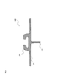
航空機の機体には、図2において断面形状を示すような座席トラックが、航空機の長手方向に沿って機体の床面に差し込まれている。 In the fuselage of the aircraft, a seat truck as shown in the cross-sectional shape in FIG. 2 is inserted into the floor surface of the aircraft along the longitudinal direction of the aircraft.
図2に示すように座席トラック280は、航空機の機体の床下の構造材となる床下構造部286、床板を支える平坦部287、及び、座席トラック側の嵌め合い部288を備える。
As shown in FIG. 2, the
そして、座席ユニットは、基本骨格の脚部が図3に示されるようなトラックフィッティング部材によって、座席トラックに固定されている。この際、従来は、座席ユニットの基本骨格の前後左右4箇所の脚部の下に、4つのトラックフィッティング部材が配設されており、2列の座席トラックと固定されている。 Then, in the seat unit, the legs of the basic skeleton are fixed to the seat truck by a track fitting member as shown in FIG. At this time, conventionally, four track fitting members are arranged under the four front, rear, left and right legs of the basic skeleton of the seat unit, and are fixed to the two rows of seat trucks.
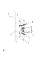
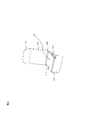
図3はトラックフィッティング部材周辺の拡大図である。取付け具270は、フィッティングブラケットとも呼ばれ、座席トラック280に固定される。フィッティング側の嵌め合い部291が、座席トラック側の嵌め合い部288と固定される。
FIG. 3 is an enlarged view of the periphery of the track fitting member. The
トラックフィッティング部材290は、縦ばね292により下方向にプランジャ293押し付けて機体前後の荷重をとらせ、取付け具270と固定するためのボルト294及びナット295とが設けられる。また、左右一対のトラックフィッティングの間隔の距離の誤差を許容する遊びを設けた時のガタを防ぐための横ばね296が設けられている。
The
このため、航空機の機体に固定された基本骨格に対して、様々な座席部品を取り付けることなる。つまり、図1の例で示すと、座席ユニットの右側については、基本骨格から通路側の方向に対して、右側シェル210、右側肘掛け部310が取り付けられることとなる。
Therefore, various seat parts are attached to the basic skeleton fixed to the fuselage of the aircraft. That is, in the example of FIG. 1, on the right side of the seat unit, the
その結果、基本骨格が設計どおりに航空機に固定された場合であっても、右側シェル210又は右側肘掛け部310の取り付けが設計どおりでなかった場合には、座席ユニット右側の通路幅が法定の通路幅を満たさない場合が発生していた。
As a result, even if the basic skeleton is fixed to the aircraft as designed, if the
(第1の実施形態)
図4は、第1の実施形態に係る座席ユニット用の構造体を前方から見た斜視図である。この座席ユニット用の構造体(以下、「シェル20」ということがある)は、下部構造体及び上部シェルを合体したシェル構造となっており、座席ユニットの最外殻を規定している。また、この座席ユニット用の構造体は、最外殻の内側の領域に座席シートを支持可能としているとともに、その底面部において航空機の機体と固定されている。
(First Embodiment)
FIG. 4 is a perspective view of the structure for the seat unit according to the first embodiment as viewed from the front. The structure for the seat unit (hereinafter, may be referred to as "shell 20") has a shell structure in which the lower structure and the upper shell are combined, and defines the outermost shell of the seat unit. Further, the structure for this seat unit is capable of supporting the seat seat in the inner region of the outermost shell, and is fixed to the aircraft body at the bottom surface thereof.
(構成)
図4において、シェル20は、座席ユニットの下部構造体である座席土台240の上方に、別部材として、右側シェル210、背面側シェル220、及び、左側シェル230からなる上部シェルを付加したものである。そしてシェル20は、座席土台240の底面部において航空機と接続固定されている。
(Constitution)
In FIG. 4, the
座席ユニットの下部構造体である座席土台240は、一体に形成された部材を用いて、中空のボックス型に形成されている。ここで、一体に形成された部材とは、具体的には、ポリエーテルイミド、ポリエーテルケトンケトンなどの熱可塑性樹脂や、適切に可燃性を制御できる熱硬化性樹脂や、カーボングラファイトファイバー、ガラスファイバー、アラミドファイバーなどの複合材料から形成される部材であって、発泡体、ハニカム等の心材を含むことができる複合部材である。このような一体に形成された複合部材は、ボルトやナットなどの接続部品を用いることなく強固な立体形状を形成することができる。また、上記のような複合材料によって形成されていることから、既存の金属の構造部材に比べ、防錆処理をする箇所を大幅に低減することができる。
The
また、中空のボックス構造は、筒型の構造形状を意味し、いわゆるモノコック構造となっている。このため、座席土台240は、座席、乗客、及び、乗客が使用する装備(読書灯360など)の荷重を支えることができる。
Further, the hollow box structure means a tubular structural shape, and is a so-called monocoque structure. Therefore, the
座席土台240の中空領域242は、座席の前方から見た形が長方形であるが、台形等の四辺形であってもよい。また、座席土台240つまり座席下部構造体を構成する部材の厚さはおよそ10mm~15mmである。
The
このような座席土台240では、機体側の座席トラックの位置によって位置の制約を受ける、1つの座席の足元を支持する柱状の支持体つまり脚部といった概念がない。このため、座席の上部構造の形状に関わらず様々な大きさ、形状の座席に対して共通の構造をとることができる。また、電気機器の取付け、これに伴う配線の配置についても、脚部の位置との制約を受けることがないため、設計の自由度の拡大や共通化を図ることができる。
In such a
また、中空領域242には、仕切り部材250を配設することもできる。座席土台240は、中空のモノコック構造であるため、仕切り部材250(仕切り板と呼ぶこともある)は、乗客等の荷重を支える必要が無く、中空領域242内で自在に移動できる。
Further, the
座席ユニット用の構造体(シェル20)は、座席ユニットの最外殻を規定しており、同時に座席ユニットに隣接する通路の幅も規定することとなる。このため、通路幅の要件として、床に近い高さ付近における通路幅を広く設定する場合には、座席土台240の上に、右側シェル210、背面側シェル220、及び、左側シェル230からなる上部シェルが座席土台240からはみ出すことなく設計すればよい。例えば、図4において、シェル20の最大幅寸法W及び最大奥行寸法Dは、座席土台240の最大幅寸法及び最大奥行寸法と一致する。
The structure for the seat unit (shell 20) defines the outermost shell of the seat unit and at the same time defines the width of the aisle adjacent to the seat unit. Therefore, as a requirement for the aisle width, when the aisle width is set wide near the height near the floor, the upper part including the
一方、床に近いところの通路幅を広く設定する必要がない場合や上部シェルに膨らみ形状を持たせる場合には、上部シェルの最大幅寸法を座席土台240の最大幅寸法よりも大きく設定しても良い。しかし、この場合には、シェル20の最大幅寸法W及び最大奥行寸法Dは、座席土台240の最大幅寸法及び最大奥行寸法とは一致しないことに留意する必要がある。
On the other hand, when it is not necessary to set a wide aisle width near the floor or when the upper shell has a bulging shape, the maximum width dimension of the upper shell is set larger than the maximum width dimension of the
また、図4に示した上部シェルは、ビジネスクラスやファーストクラスの場合の例を示しており、着座している乗客同士の視線が遮られるよう、プライバシー確保用のサイドシェルとして構成されている。一方、エコノミークラスの場合、図示しないが、右側シェル210及び左側シェル230は肘掛け程度の高さで設けられる。
Further, the upper shell shown in FIG. 4 shows an example in the case of business class or first class, and is configured as a side shell for ensuring privacy so that the line of sight of seated passengers is blocked. On the other hand, in the case of economy class, although not shown, the
なお、「座席ユニットの最外殻を規定する」とは、水平面上の特定の一方向において、座席ユニットのすべての構成部材が座席ユニット用の構造体(シェル20)の内側領域に納まっている状態を意味している。 In addition, "defining the outermost shell of the seat unit" means that all the constituent members of the seat unit are housed in the inner region of the structure (shell 20) for the seat unit in a specific direction on the horizontal plane. It means a state.
図5は、第1の実施形態に係るシェル構造を斜め前方から見た斜視図であり、座席10を取付ける前の状態を示す。座席土台240の上に、座席10の上部シート120を支えるための上部シート用支持体160を配設する。また、上部シート用支持体の右隣には、コンソールと後席のレッグスペースを兼ねた収納ボックス330を配設する。
FIG. 5 is a perspective view of the shell structure according to the first embodiment as viewed diagonally from the front, and shows a state before the
さらに、座席土台240の上面であって、座席10が搭載される部分に、局部的な補強部材170を更に配設することも可能である。
Further, it is also possible to further dispose the local reinforcing
このように、シェル構造の内側に、収納ボックス330や補強部材170などを配設したとしても、これらはすべてシェル20の内側の領域に配置されている
In this way, even if the
図6は、第1の実施形態に用いる座席シートの例を斜め前方から見た斜視図である。座席10は、乗客が着座する下部シート110、背中をもたせ掛ける上部シート120、背もたれの上部の枕状の部分であり、頭を乗せて首などを休ませるヘッドレスト130、及び、脚を乗せてふくらはぎ等の疲れを軽減させるレッグレスト140を備える。
FIG. 6 is a perspective view of an example of a seat seat used in the first embodiment as viewed diagonally from the front. The
座席リクライニング機構180は、上部シート120を後方に傾けさせる機構である。フット・リクライニング機構190は、レッグレスト140を下部シート110の面近くまで持ち上げるように回転させる機構である。
The
図7は、図5を用いて説明したシェル20に、図7を用いて説明した座席10を乗せた形態を斜め前方から見た斜視図である。
FIG. 7 is a perspective view of a form in which the
ここで、座席ユニット1の奥行寸法は、レッグレスト140がシェル20から前方にはみ出すため、シェル20の最大奥行寸法Dよりも大きくなる。しかし、座席ユニット1の前方は乗客の脚を置くスペースであり、座席間の通路幅のように法令によって定められているものではないので、緊急時に避難できる程度の幅が確保できればよい。
Here, the depth dimension of the
これに対し、座席ユニット1の幅寸法は、座席部品がすべてシェル20の幅方向の内側の領域に配置されているため、シェル20の最大幅寸法Wと変わらない。すなわち、航空機内で全ての座席部品をシェル20に設置した後であっても座席ユニット1の幅寸法は、シェル20の最大幅寸法Wで固定されており、座席部品を取り付けたことによって変化することがない。
On the other hand, the width dimension of the
なお、図7において、右側シェル210が窓側の側面である場合であっても、化粧用ミラーやサイドボードなどの装備もすべてシェル20の内側の領域に装着することができる。すなわち、その座席ユニットに座る人が利用する全ての取付け部材がシェル20内の少なくとも最外殻内側に収納可能である。
In FIG. 7, even when the
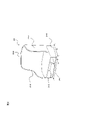
図8は、第1の実施形態に係る座席ユニットの下部構造体である座席土台を斜め後方から見た斜視図である。シェル20は、後述する座席トラックを説明する便宜上、背面側シェル220を省略し、右側シェル210及び左側シェル230を図示している。
FIG. 8 is a perspective view of the seat base, which is the lower structure of the seat unit according to the first embodiment, as viewed diagonally from the rear. For convenience of explaining the seat truck described later, the
第1の座席トラック282及び第2の座席トラック284は一対の座席トラックを構成し、航空機の機体の長手方向の床面に延在している。航空機では、座席ユニット1の底部(図8では座席土台240の底部)が一対の座席トラックに固定されることによって、座席ユニット1が航空機の機体に取り付けられ、所定の動荷重試験に合格することが、乗客の安全を確保する上で必要である。図8では、座席土台240は、航空機の機体の長手方向に対し、少し左側に向いて配設した状態を示している。このため、座席土台240は第1の座席トラック282及び第2の座席トラック284に正対しておらず、少し左側に向いている。
The
座席土台240の底部には、3個の取付けブロックが配置されている(取付けブロックは点線で表示)。座席土台240は、3個の取付けブロックを介して、航空機の機体へ取り付けるための3個の取付け具に固定されている。座席土台240はモノコック構造であって、柱状の脚部を有しないため、取付けブロックが座席土台240の底部に設けられ、取付け具と座席土台240との接続を補強している。取付けブロックの材質は金属製などが望ましいが、補強用のブロックであればその材料は限定されない。
Three mounting blocks are arranged at the bottom of the seat base 240 (the mounting blocks are indicated by dotted lines). The
図8では、座席土台240を3箇所で航空機の機体に取付けるため、第1の取付けブロック262が座席土台240の底部の前方に配置され、その後方に第2の取付けブロック264が配置されている。第3の取付けブロック266は、右側に配置されている。
In FIG. 8, in order to attach the
各取付けブロックの下には、座席トラックへの取付け具がそれぞれ配設されている(取付け具は実線で表示)。すなわち、第1の取付け具272は、第1の取付けブロック262の下に配設され、第1の座席トラック282に取付けられる。第2の取付け具274は、第2の取付けブロック264の下に配設され、第1の座席トラック282であって、第1の取付け具272から間隔を隔てた点に取付けられる。
Under each mounting block, a mounting tool for the seat truck is arranged (the mounting tool is indicated by a solid line). That is, the
一方、第3の取付け具276は、第3の取付けブロック266の下に配設され、第2の座席トラック284であって、第1の取付け具272と第2の取付け具274との間に対応する部分に取り付けられる。望ましくは、第1の取付け具272と第2の取付け具274との間に対応する部分の略中央に取り付けられる。
On the other hand, the
ちなみに、図9は、第1の実施形態に係る座席土台240の底部周辺の拡大図である。座席土台240の底部は、中空領域242側の内面244と、反対側の外面246との間がハニカム構造248になっている。このハニカム構造248の中に、取付けブロック260が配設されている。取付けブロック260と取付け具270とはボルトとナット等によって固定されている。内面244及び外面246の材料は例えば樹脂と繊維による複合繊維である。ハニカム構造248の材料は例えば不燃性の紙とフェーノル樹脂による複合繊維である。
Incidentally, FIG. 9 is an enlarged view of the vicinity of the bottom of the
取付けブロック260であって、下に取付け具270が配設される部分の厚さは、薄くなっている。座席土台240の底部であって、下に取付け具270が配設される部分の厚さも、同様に薄くなっている。座席土台240の底部及び取付けブロック260の一部をこのように薄く凹部247を設けることによって、座席土台240の底部の内面244を平坦に保つことができ、中空領域242内に、乗客の脚を入れたり、荷物を収納したりする際に便利である。
The thickness of the portion of the mounting
このように3つの取付け具によって、座席土台240を一対の座席トラックに固定することによって、座席土台240を座席トラックに正対しない態様で取り付けることができる。これによって、機内の座席配置の自由度を格段に向上することができる。
By fixing the
再度、図8について説明する。第1の座席トラック282及び第2の座席トラック284は、航空機の機体の長手方向の床面に延在している。そして、座席トラック282及び284に対する座席土台240の傾き角度及び座席土台240の最大幅寸法Wを用いれば、座席トラック282及び284の垂直方向(つまり、航空機の長手方向に直行する横幅方向)に対しての座席土台240の占有幅の寸法を一義的に計算することができる。この最大占有寸法(以下、「修正寸法」という)をW’とする(不図示)。
FIG. 8 will be described again. The
図10は、第1の実施形態に座席土台間の間隔を説明するための図である。座席土台240aの最大幅寸法Waから、図8で説明した通り、座席トラック282a及び284aの垂直方向に対してどのくらいの最大占有寸法になるかを計算し、修正寸法Wa’(不図示)を求める。同様に、座席土台240bの最大幅寸法Wbから、修正寸法Wb’(不図示)を求める。
FIG. 10 is a diagram for explaining the spacing between the seat bases in the first embodiment. From the maximum width dimension Wa of the
次に、座席土台を取り付ける機体の構造設計書から、2つの座席土台の内側の座席トラック間(284aと282bとの間)の寸法W1を求める。そして、修正寸法Wa’及び修正寸法Wb’の測定方向が座席ユニットの最外殻を規定している方向に含まれていれば、このW1と、修正寸法Wa’(不図示)、Wb’(不図示)と、内側の座席トラック284a及び282bと固定される取付け具272b、274b及び276aとの位置関係から、2つの座席土台の間隔W2、つまり、2つの座席ユニット間の間隔を求めることができる。
Next, the dimension W1 between the seat trucks (between 284a and 282b) inside the two seat bases is obtained from the structural design document of the aircraft to which the seat bases are attached. If the measurement directions of the modified dimension Wa'and the modified dimension Wb' are included in the direction defining the outermost shell of the seat unit, this W1 and the modified dimension Wa'(not shown), Wb'(not shown). From the positional relationship between the
このW2が、該当する通路側の座席間の幅になり、法令で定められている寸法(例えば51cm)以上あればよい。このような計算作業を、航空機の機体の最前列の座席から最後尾の座席まで計算し、全ての通路側の座席間の幅が法定で定められている寸法以上であれば、問題が無いことになる。 It is sufficient that this W2 is the width between the seats on the corresponding aisle side and is equal to or larger than the dimension (for example, 51 cm) specified by law. There is no problem if such calculation work is calculated from the front row seats to the rearmost seats of the aircraft and the width between all aisle seats is equal to or greater than the legally required dimensions. become.
なお、法令上の規制は窓側との間隔には言及されないが、機体の構造設計書から、該当する座席トラックと、窓側との寸法を求めることによって、同様に適正な間隔を確保することができる。 Although legal regulations do not mention the distance from the window side, it is possible to secure the appropriate distance as well by obtaining the dimensions between the relevant seat truck and the window side from the structural design document of the aircraft. ..
次に、第1の実施態様を実現するための製造プロセス及び航空機の機体への取り付けプロセスを説明する。第1の実施態様に用いられる座席ユニット用の構造体は、ポリエーテルイミド、ポリエーテルケトンケトンなどの熱可塑性樹脂や、適切に可燃性を制御できる熱硬化性樹脂や、カーボングラファイトファイバー、ガラスファイバー、アラミドファイバーなどの複合材料から形成される部材に、必要に応じて、発泡体、ハニカム等の心材を組み合わせて、一体に形成する。 Next, a manufacturing process and an aircraft mounting process for realizing the first embodiment will be described. The structure for the seat unit used in the first embodiment is a thermoplastic resin such as polyetherimide or polyetherketoneketone, a thermosetting resin whose flammability can be appropriately controlled, carbon graphite fiber, or glass fiber. , Aramid fiber and other composite materials are combined with core materials such as foams and honeycombs, if necessary, to form them integrally.
そして、このような座席ユニットの航空機機体への取付けプロセスは、2種類の方法がある。一つは、座席ユニット用の構造体に、座席シートをはじめとする座席部品を装着し、ほぼ完成した座席ユニットを航空機の機体に取り付ける方法である。他の取り付け方法は、座席ユニットようの構造体を航空機の機体に取り付けた後に、座席シートをはじめとする座席部品を取り付ける方法である。 There are two methods for attaching such a seat unit to an aircraft body. One is a method in which seat parts such as seats are attached to a structure for a seat unit, and the almost completed seat unit is attached to the aircraft body. Another attachment method is to attach a structure such as a seat unit to the aircraft body, and then attach seat parts such as seats.
(作用効果)
第1の実施形態によれば、座席ユニットの構造体(シェル20)は、座席土台240の底面部において航空機と接続固定されており、座席ユニットの最外殻を規定していることから、座席部品を取り付けても、これによって、通路側に横幅が増加することがない。このため、座席ユニットを航空機の機体に取り付ける前の段階で、通路幅を確定することが可能となる。また、座席ユニットの構造体を航空機に接続固定した後に、座席部品を取り付けたとしても、所定の通路幅が変化することはなく、座席部品取り付けをやり直すことがなくなる。
(Action effect)
According to the first embodiment, the structure of the seat unit (shell 20) is connected and fixed to the aircraft at the bottom surface of the
また、座席ユニットと窓側との間隔についても、座席ユニット同士の場合と同様に、座席ユニットを航空機の機体に取り付ける前の段階で間隔を予め確定できるという効果を有する。 Further, regarding the distance between the seat unit and the window side, there is an effect that the distance can be determined in advance before the seat unit is attached to the aircraft body, as in the case of the seat units.
さらに、第1の実施形態によれば、座席ユニットを座席トラックの位置に影響されること無く、大きな自由度をもって取り付けることができる。これに加えて、第1の実施形態では、座席ユニットが座席トラックに取り付けられる角度と、これによって確保できる通路幅を容易に確定することができるので、航空機の機内における座席配置の設計を容易に行うことができる。 Further, according to the first embodiment, the seat unit can be mounted with a large degree of freedom without being influenced by the position of the seat truck. In addition to this, in the first embodiment, the angle at which the seat unit is attached to the seat truck and the aisle width that can be secured by the angle can be easily determined, so that the design of the seat arrangement in the aircraft can be easily performed. It can be carried out.
加えて、座席トラックの位置に関わらず、足元のスペースを広く確保でき、乗客は好きな所に脚を伸ばせるという効果を有する。 In addition, regardless of the position of the seat truck, a large space under the feet can be secured, and passengers have the effect of extending their legs wherever they like.
さらに、航空機の製造プロセスにおいて、座席ユニット用の構造体の製造・設置工程と、座席シートをはじめとする座席部品の製造・設置工程を完全に分離し、別個の事業者が別個の工程で行うことが可能となる。また、航空機本体の機体メーカーが座席ユニットの構造体を開発して提供すれば、座席メーカーは座席土台に関わる試験証明を行うことが容易になり、開発期間の短縮に繋がるという効果も有する。 Furthermore, in the aircraft manufacturing process, the manufacturing and installation process of the structure for the seat unit and the manufacturing and installation process of the seat parts such as the seat seat are completely separated, and are performed by separate operators in separate processes. It becomes possible. Further, if the aircraft manufacturer of the aircraft body develops and provides the structure of the seat unit, the seat manufacturer can easily perform the test certification related to the seat base, which has the effect of shortening the development period.
(第2の実施形態)
次に、図11を用いて第2の実施形態を説明する。図11は、第1の実施形態で説明した、座席土台240と上部シェルが一体に成型した座席ユニットの構造体(シェル20)を示している。座席土台240と上部シェルを一体に成型した以外の点は第1の実施形態と同じである。
(Second embodiment)
Next, the second embodiment will be described with reference to FIG. FIG. 11 shows the structure (shell 20) of the seat unit in which the
(構成)
第2の実施形態においては、座席土台240及び上部シェルが共に一体成型され、一体でモノコック構造を実現している。最大幅寸法Wや、一体成型される部材に用いる複合材料などについても、第1の実施形態と同じである。
(Constitution)
In the second embodiment, the
(作用効果)
第2の実施形態によれば、第1の実施形態と同様の効果を有し、さらに、座席土台240の最外殻と上部シェルの最外殻を合わせる作業が不要になるという効果を有する。
(Action effect)
According to the second embodiment, it has the same effect as that of the first embodiment, and further has an effect that the work of aligning the outermost shell of the
加えて、座席土台と上部シェルとが一体となっていることから、座席全体の強度を向上させることができる。その上、取付け作業を簡略化できるという効果を有する。 In addition, since the seat base and the upper shell are integrated, the strength of the entire seat can be improved. In addition, it has the effect of simplifying the installation work.
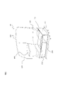
(第3の実施形態)
次に、図12を用いて第3の実施形態を説明する。図12は、装飾が施された座席ユニットの構造体(シェル20)を示す斜視図である。シェル20は、第1の実施形態で説明した、右側シェル210、背面側シェル220、及び、左側シェル230に加え、シェルの上面から両側面にかけて保護する保護カバー410と、シェルの端面を保護する端面カバー420を備える。つまり、座席ユニット用の構造体の外周面に緩衝・装飾部材(緩衝及び/又は装飾部材)が設けられている。
(Third embodiment)
Next, a third embodiment will be described with reference to FIG. FIG. 12 is a perspective view showing the structure (shell 20) of the decorated seat unit. In addition to the
保護カバー410は、乗客や客室乗務員が通路を歩く際に、シェル20に接触するため、ラバーやスポンジなど柔らかい素材で構成され、乗客や乗務員がシェル20を構成している硬質の熱可塑性樹脂、熱硬化性樹脂、カーボングラファイトなどの複合材料などに直接に接触しないよう保護している。また、端面カバー420は、食事を運ぶカートなどがシェル20を構成している硬質の材料に直接接触しないようにするためのものであり、右側シェル210のみならず左側シェル230の下端も覆っている。
The
第3の実施形態の場合、右側シェル210及び左側シェル230に加え、保護カバー410及び端面カバー420が、座席ユニットから、座席ユニットの最大幅寸法最外殻を規定している。
In the case of the third embodiment, in addition to the
また、保護カバー410及び端面カバー420は、複合材料で一体形成されたシェル20に装飾を施すという機能も有している。あるいは、シェル20に直接ペイントを施しておき、透明な保護カバー410及び端面の装飾カバー420で覆ってもよい。
Further, the
また、背面側シェル220には、ディスプレイを設置してもよい。あるいは、後ろの座席に座っている人が使う物入れ、コンセント、化粧用の鏡などを配置してもよい。
Further, a display may be installed on the
(作用効果)
第3の実施形態によれば、第1の実施形態と同様の効果を有し、さらに、乗客や客室乗務員、カートなどがシェル20を構成している硬質の材料に直接に触れないようにするという効果を有する。
(Action effect)
According to the third embodiment, it has the same effect as that of the first embodiment, and further prevents passengers, cabin crew, carts, and the like from directly touching the hard material constituting the
加えて、保護カバー410及び端面カバー420の装飾を機内の座席で統一させることにより、各航空会社のブランド向上にも役立つという効果を有する。
In addition, by unifying the decoration of the
なお、本発明は上記した航空機の座席ユニットに適用した例で説明したが、本発明の対象は航空機に限定されるものではなく、航空機以外の様々な移動体の座席に適用されうるものであり、様々な変形例が含まれる。例えば、列車、長距離バス、および客船、フェリー、およびホーバー・クラフトを含む水上輸送機関のような他の形式の乗物や移動体にも適切に使用できる。 Although the present invention has been described by the above-mentioned example applied to the seat unit of an aircraft, the subject of the present invention is not limited to the aircraft, but can be applied to the seats of various moving objects other than the aircraft. , Various variants are included. It can also be successfully used for other types of vehicles and vehicles such as trains, long-distance buses, and water transport including passenger ships, ferries, and hovercraft.
また、上記した実施例は本発明を分かりやすく説明するために詳細に説明したものであり、必ずしも説明した全ての構成を備えるものに限定されるものではない。また、ある実施例の構成の一部を他の実施例の構成に置き換えることが可能であり、また、ある実施例の構成に他の実施例の構成を加えることも可能である。また、各実施例の構成の一部について、他の構成の追加・削除・置換をすることが可能である。 Further, the above-described embodiment has been described in detail in order to explain the present invention in an easy-to-understand manner, and is not necessarily limited to the one including all the described configurations. Further, it is possible to replace a part of the configuration of one embodiment with the configuration of another embodiment, and it is also possible to add the configuration of another embodiment to the configuration of one embodiment. Further, it is possible to add / delete / replace a part of the configuration of each embodiment with another configuration.
1 座席ユニット
10 座席
20 シェル
110 下部シート
120 上部シート
130 ヘッドレスト
140 レッグレスト
150 シートベルト
160 上部シート用支持体
170 補強部材
180 座席リクライニング機構
190 フット・リクライニング機構
210 右側シェル
220 背面側シェル
230 左側シェル
240 座席土台
242 中空領域
244 内面
246 外面
247 凹部
248 ハニカム構造
250 仕切り部材
260 取付けブロック
262 第1の取付けブロック
264 第2の取付けブロック
266 第3の取付けブロック
270 取付け具
272 第1の取付け具
274 第2の取付け具
276 第3の取付け具
280 座席トラック
282 第1の座席トラック
284 第2の座席トラック
286 床下構造部
287 平坦部
288 座席トラック側の嵌め合い部
290 トラックフィッティング部材
291 フィッティング側の嵌め合い部
292 縦ばね
293 プランジャ
294 ボルト
295 ナット
296 横ばね
310 右側肘掛け部
320 左側肘掛け部
330 収納ボックス
340 オットマン
350 ジャック
360 読書灯
410 保護カバー
420 端面カバー
1
Claims (6)
前記座席ユニット用の構造体は、前記座席ユニットの少なくとも一方向において、前記座席ユニットの最外殻を規定しており、
前記下部構造体は、樹脂または複合部材を用いて、背後の乗客の脚または荷物を収容可能である中空のボックス型に一体的に形成された座席土台であって、
前記下部構造体は、前記下部構造体の幅方向にわたって平板状に延在する底面部と、前記底面部の幅方向両端から前記上部シェルに向かって延在する一対の側壁部とを有し、前記底面部と前記側壁部の前後方向の長さは等しく、前記底面部の後縁と、前記側壁部の後縁と、前記下部構造体の上壁部とにより開口が画成されており、
前記底面部において前記座席ユニットを移動体に接続固定している、座席ユニット用の構造体。 A structure for a seat unit consisting of a lower structure and an upper shell installed above the lower structure.
The structure for the seat unit defines the outermost shell of the seat unit in at least one direction of the seat unit.
The substructure is a seating base integrally formed in a hollow box shape capable of accommodating the legs or luggage of passengers behind, using resin or composite members.
The lower structure has a bottom surface portion extending in a flat plate shape over the width direction of the lower structure portion, and a pair of side wall portions extending from both ends in the width direction of the bottom surface portion toward the upper shell. The bottom surface portion and the side wall portion have the same length in the front-rear direction, and an opening is defined by the trailing edge of the bottom surface portion, the trailing edge of the side wall portion, and the upper wall portion of the lower structure.
A structure for a seat unit in which the seat unit is connected and fixed to a moving body at the bottom surface portion.
前記一方向は、前記移動体の横幅方向である請求項1に記載の座席ユニット用の構造体。 The lower structure is a monocoque structure and has a monocoque structure.
The structure for a seat unit according to claim 1, wherein the one direction is the lateral width direction of the moving body.
前記座席シートを支持可能な、請求項1に記載の座席ユニット用の構造体からなる座席ユニットであって、
前記座席ユニット用の構造体は、前記座席ユニットの少なくとも一方向において最外殻を規定している座席ユニット。 Seats and
A seat unit having the structure for the seat unit according to claim 1, which can support the seat.
The structure for the seat unit is a seat unit that defines the outermost shell in at least one direction of the seat unit.
座席ユニットに必要な座席シートを前記座席ユニット用の構造体に設置するステップからなる
座席ユニットの取付け方法。 The step of connecting and fixing the structure for the seat unit according to claim 1 to the moving body,
A method for mounting a seat unit, which comprises a step of installing a seat required for the seat unit in the structure for the seat unit.
Priority Applications (5)
| Application Number | Priority Date | Filing Date | Title |
|---|---|---|---|
| JP2017073604A JP7043180B2 (en) | 2017-04-03 | 2017-04-03 | Structure for seat unit, seat unit and its mounting method |
| US16/500,255 US11325711B2 (en) | 2017-04-03 | 2017-12-18 | Seat unit structure, seat unit, and attachment method thereof |
| SG11201908811U SG11201908811UA (en) | 2017-04-03 | 2017-12-18 | Seat unit structure, seat unit, and attachment method thereof |
| PCT/JP2017/045275 WO2018185979A1 (en) | 2017-04-03 | 2017-12-18 | Structure for seat unit, seat unit, and attachment method thereof |
| EP17904531.5A EP3608161B1 (en) | 2017-04-03 | 2017-12-18 | Structure for seat unit, seat unit, and attachment method thereof |
Applications Claiming Priority (1)
| Application Number | Priority Date | Filing Date | Title |
|---|---|---|---|
| JP2017073604A JP7043180B2 (en) | 2017-04-03 | 2017-04-03 | Structure for seat unit, seat unit and its mounting method |
Publications (3)
| Publication Number | Publication Date |
|---|---|
| JP2018176770A JP2018176770A (en) | 2018-11-15 |
| JP2018176770A5 JP2018176770A5 (en) | 2020-05-14 |
| JP7043180B2 true JP7043180B2 (en) | 2022-03-29 |
Family
ID=63712423
Family Applications (1)
| Application Number | Title | Priority Date | Filing Date |
|---|---|---|---|
| JP2017073604A Active JP7043180B2 (en) | 2017-04-03 | 2017-04-03 | Structure for seat unit, seat unit and its mounting method |
Country Status (5)
| Country | Link |
|---|---|
| US (1) | US11325711B2 (en) |
| EP (1) | EP3608161B1 (en) |
| JP (1) | JP7043180B2 (en) |
| SG (1) | SG11201908811UA (en) |
| WO (1) | WO2018185979A1 (en) |
Families Citing this family (6)
| Publication number | Priority date | Publication date | Assignee | Title |
|---|---|---|---|---|
| JP7043180B2 (en) * | 2017-04-03 | 2022-03-29 | 株式会社ジャムコ | Structure for seat unit, seat unit and its mounting method |
| JP6994840B2 (en) * | 2017-04-03 | 2022-01-14 | 株式会社ジャムコ | Rear shell structure and seat unit |
| JP6971608B2 (en) * | 2017-04-03 | 2021-11-24 | 株式会社ジャムコ | Seat unit and its substructure |
| US20210229813A1 (en) * | 2018-06-13 | 2021-07-29 | Safran Seats Usa Llc | Lightweight passenger privacy screen |
| USD1020327S1 (en) * | 2019-03-29 | 2024-04-02 | Safran Seats | Cabinet for seat |
| US20220332421A1 (en) * | 2021-04-16 | 2022-10-20 | B/E Aerospace, Inc. | Aircraft interior structure including improved bassinet provisions |
Citations (6)
| Publication number | Priority date | Publication date | Assignee | Title |
|---|---|---|---|---|
| JP2004537459A (en) | 2001-08-09 | 2004-12-16 | ヴァージン アトランティック エアウェイズ リミテッド | Vehicle seating systems and passenger accommodation units |
| US20060163917A1 (en) | 2004-10-14 | 2006-07-27 | Airbus Deutschland Gmbh | Passenger seat with luggage compartment |
| JP2007524542A (en) | 2004-02-18 | 2007-08-30 | リーダーン インヴェストメンツ リミテッド | Aircraft seat units and seat sets |
| JP2008521703A (en) | 2004-12-02 | 2008-06-26 | ジェイムズ パーク アソシエイツ リミテッド | Aircraft seat support structure |
| JP2014162479A (en) | 2013-02-27 | 2014-09-08 | Boeing Co | Variable thermal resistance device for vehicular seats |
| JP2016529148A (en) | 2013-07-08 | 2016-09-23 | ラジャーシンガム、アージューナ・イドレイスワラン | Vehicle occupant support |
Family Cites Families (14)
| Publication number | Priority date | Publication date | Assignee | Title |
|---|---|---|---|---|
| GB9617706D0 (en) * | 1996-08-22 | 1996-10-02 | Britax Rumbold Ltd | Vehicle seat |
| US7021596B2 (en) * | 2004-02-11 | 2006-04-04 | Goodrich Corporation | Aircraft seat floor track quick release fitting |
| DE102004063094B4 (en) * | 2004-12-22 | 2010-05-12 | Airbus Deutschland Gmbh | Passenger seating unit, in particular for commercial aircraft |
| US20080088166A1 (en) * | 2006-10-16 | 2008-04-17 | Gardiner Richard J | Aircraft seat |
| US7871039B2 (en) | 2007-05-22 | 2011-01-18 | The Boeing Company | Modular passenger seat for an aircraft |
| FR2943286B3 (en) | 2009-03-23 | 2011-02-25 | Air New Zealand Ltd | IMPROVEMENTS IN OR RELATING TO PASSENGER SEATS IN A VEHICLE |
| US8231097B2 (en) * | 2009-09-11 | 2012-07-31 | Ami Industries, Inc. | Aircraft equipment support |
| CA2850227C (en) * | 2011-06-07 | 2021-06-01 | Composite Helicopter Holdings Limited | A helicopter |
| US11208213B2 (en) * | 2017-03-30 | 2021-12-28 | The Boeing Company | Integrated aircraft fuselage and load-bearing structural base for aircraft seats |
| JP6971608B2 (en) * | 2017-04-03 | 2021-11-24 | 株式会社ジャムコ | Seat unit and its substructure |
| JP7043180B2 (en) * | 2017-04-03 | 2022-03-29 | 株式会社ジャムコ | Structure for seat unit, seat unit and its mounting method |
| US11279489B2 (en) * | 2017-10-26 | 2022-03-22 | Jing Zheng | Lie-flat passenger seat configurations for transportation |
| DE102018115776B4 (en) * | 2018-06-29 | 2023-12-21 | Airbus Operations Gmbh | Seat frame mounting assembly, seat frame, vehicle section and vehicle with a seat frame mounting assembly |
| US10829225B2 (en) * | 2018-12-11 | 2020-11-10 | Ami Industries, Inc. | Track fitting with quick release lock for aircraft seating |
-
2017
- 2017-04-03 JP JP2017073604A patent/JP7043180B2/en active Active
- 2017-12-18 US US16/500,255 patent/US11325711B2/en active Active
- 2017-12-18 EP EP17904531.5A patent/EP3608161B1/en active Active
- 2017-12-18 SG SG11201908811U patent/SG11201908811UA/en unknown
- 2017-12-18 WO PCT/JP2017/045275 patent/WO2018185979A1/en unknown
Patent Citations (6)
| Publication number | Priority date | Publication date | Assignee | Title |
|---|---|---|---|---|
| JP2004537459A (en) | 2001-08-09 | 2004-12-16 | ヴァージン アトランティック エアウェイズ リミテッド | Vehicle seating systems and passenger accommodation units |
| JP2007524542A (en) | 2004-02-18 | 2007-08-30 | リーダーン インヴェストメンツ リミテッド | Aircraft seat units and seat sets |
| US20060163917A1 (en) | 2004-10-14 | 2006-07-27 | Airbus Deutschland Gmbh | Passenger seat with luggage compartment |
| JP2008521703A (en) | 2004-12-02 | 2008-06-26 | ジェイムズ パーク アソシエイツ リミテッド | Aircraft seat support structure |
| JP2014162479A (en) | 2013-02-27 | 2014-09-08 | Boeing Co | Variable thermal resistance device for vehicular seats |
| JP2016529148A (en) | 2013-07-08 | 2016-09-23 | ラジャーシンガム、アージューナ・イドレイスワラン | Vehicle occupant support |
Also Published As
| Publication number | Publication date |
|---|---|
| SG11201908811UA (en) | 2019-10-30 |
| JP2018176770A (en) | 2018-11-15 |
| US11325711B2 (en) | 2022-05-10 |
| EP3608161A1 (en) | 2020-02-12 |
| EP3608161B1 (en) | 2022-08-03 |
| WO2018185979A1 (en) | 2018-10-11 |
| EP3608161A4 (en) | 2021-01-06 |
| US20210114735A1 (en) | 2021-04-22 |
Similar Documents
| Publication | Publication Date | Title |
|---|---|---|
| JP7043180B2 (en) | Structure for seat unit, seat unit and its mounting method | |
| JP6971608B2 (en) | Seat unit and its substructure | |
| CN110431039B (en) | Passenger seat with movable backrest part | |
| US7399037B2 (en) | Double-spar chassis for aircraft passenger seat | |
| JP2010527835A (en) | Aircraft modular passenger seat | |
| JP2013522122A (en) | Passenger seat assembly and method with associated floorboard and aircraft sidewall attachment | |
| JP4999218B2 (en) | Privacy and support equipment | |
| JP6017952B2 (en) | Vehicle seat | |
| WO2018185980A1 (en) | Rear shell structure and seat unit | |
| CN115402516A (en) | Seat assembly and passenger seat arrangement | |
| EP4116194A1 (en) | Passenger seating positioned proximate to an aircraft interior structure | |
| WO2018185981A1 (en) | Seat unit and attachment method thereof | |
| CN102218996A (en) | Arrangement structure of seat and safety belt device of limo | |
| JP7300035B2 (en) | Seat unit and its mounting method | |
| US10994846B2 (en) | Functional unit in a passenger cabin, including a support unit and a passenger seat system | |
| JP6450635B2 (en) | Vehicle seat | |
| US20230322390A1 (en) | Integrated partition wall arrangement having a cabin attendant seat, carrier structure and methods for producing and designing a carrier structure or a partition wall arrangement | |
| CN202080154U (en) | Recreation vehicle seat and safety belt device arrangement structure | |
| US9174736B2 (en) | Air passenger seat having a frame | |
| CN117043007A (en) | Modular passenger cabin trim |
Legal Events
| Date | Code | Title | Description |
|---|---|---|---|
| A521 | Request for written amendment filed |
Free format text: JAPANESE INTERMEDIATE CODE: A523 Effective date: 20200401 |
|
| A621 | Written request for application examination |
Free format text: JAPANESE INTERMEDIATE CODE: A621 Effective date: 20200401 |
|
| A131 | Notification of reasons for refusal |
Free format text: JAPANESE INTERMEDIATE CODE: A131 Effective date: 20210608 |
|
| A521 | Request for written amendment filed |
Free format text: JAPANESE INTERMEDIATE CODE: A523 Effective date: 20210730 |
|
| A131 | Notification of reasons for refusal |
Free format text: JAPANESE INTERMEDIATE CODE: A131 Effective date: 20211214 |
|
| A521 | Request for written amendment filed |
Free format text: JAPANESE INTERMEDIATE CODE: A523 Effective date: 20220208 |
|
| TRDD | Decision of grant or rejection written | ||
| A01 | Written decision to grant a patent or to grant a registration (utility model) |
Free format text: JAPANESE INTERMEDIATE CODE: A01 Effective date: 20220301 |
|
| A61 | First payment of annual fees (during grant procedure) |
Free format text: JAPANESE INTERMEDIATE CODE: A61 Effective date: 20220316 |
|
| R150 | Certificate of patent or registration of utility model |
Ref document number: 7043180 Country of ref document: JP Free format text: JAPANESE INTERMEDIATE CODE: R150 |