WO2018185979A1 - 座席ユニット用の構造体、座席ユニット及びその取付け方法 - Google Patents
座席ユニット用の構造体、座席ユニット及びその取付け方法 Download PDFInfo
- Publication number
- WO2018185979A1 WO2018185979A1 PCT/JP2017/045275 JP2017045275W WO2018185979A1 WO 2018185979 A1 WO2018185979 A1 WO 2018185979A1 JP 2017045275 W JP2017045275 W JP 2017045275W WO 2018185979 A1 WO2018185979 A1 WO 2018185979A1
- Authority
- WO
- WIPO (PCT)
- Prior art keywords
- seat
- seat unit
- shell
- aircraft
- unit
- Prior art date
- Legal status (The legal status is an assumption and is not a legal conclusion. Google has not performed a legal analysis and makes no representation as to the accuracy of the status listed.)
- Ceased
Links
Images


Classifications
-
- B—PERFORMING OPERATIONS; TRANSPORTING
- B64—AIRCRAFT; AVIATION; COSMONAUTICS
- B64D—EQUIPMENT FOR FITTING IN OR TO AIRCRAFT; FLIGHT SUITS; PARACHUTES; ARRANGEMENT OR MOUNTING OF POWER PLANTS OR PROPULSION TRANSMISSIONS IN AIRCRAFT
- B64D11/00—Passenger or crew accommodation; Flight-deck installations not otherwise provided for
- B64D11/06—Arrangements of seats, or adaptations or details specially adapted for aircraft seats
- B64D11/0649—Seats characterised by special features for reducing weight
-
- B—PERFORMING OPERATIONS; TRANSPORTING
- B60—VEHICLES IN GENERAL
- B60N—SEATS SPECIALLY ADAPTED FOR VEHICLES; VEHICLE PASSENGER ACCOMMODATION NOT OTHERWISE PROVIDED FOR
- B60N2/00—Seats specially adapted for vehicles; Arrangement or mounting of seats in vehicles
- B60N2/005—Arrangement or mounting of seats in vehicles, e.g. dismountable auxiliary seats
- B60N2/015—Attaching seats directly to vehicle chassis
- B60N2/01508—Attaching seats directly to vehicle chassis using quick release attachments
- B60N2/01516—Attaching seats directly to vehicle chassis using quick release attachments with locking mechanisms
- B60N2/01558—Attaching seats directly to vehicle chassis using quick release attachments with locking mechanisms with key and slot
- B60N2/01575—Attaching seats directly to vehicle chassis using quick release attachments with locking mechanisms with key and slot key sliding inside the vehicle floor or rail
-
- B—PERFORMING OPERATIONS; TRANSPORTING
- B60—VEHICLES IN GENERAL
- B60N—SEATS SPECIALLY ADAPTED FOR VEHICLES; VEHICLE PASSENGER ACCOMMODATION NOT OTHERWISE PROVIDED FOR
- B60N2/00—Seats specially adapted for vehicles; Arrangement or mounting of seats in vehicles
- B60N2/68—Seat frames
- B60N2/686—Panel like structures
-
- B—PERFORMING OPERATIONS; TRANSPORTING
- B64—AIRCRAFT; AVIATION; COSMONAUTICS
- B64D—EQUIPMENT FOR FITTING IN OR TO AIRCRAFT; FLIGHT SUITS; PARACHUTES; ARRANGEMENT OR MOUNTING OF POWER PLANTS OR PROPULSION TRANSMISSIONS IN AIRCRAFT
- B64D11/00—Passenger or crew accommodation; Flight-deck installations not otherwise provided for
- B64D11/06—Arrangements of seats, or adaptations or details specially adapted for aircraft seats
- B64D11/0601—Arrangement of seats for non-standard seating layouts, e.g. seats staggered horizontally or vertically, arranged in an angled or fishbone layout, or facing in other directions than the direction of flight
-
- B—PERFORMING OPERATIONS; TRANSPORTING
- B64—AIRCRAFT; AVIATION; COSMONAUTICS
- B64D—EQUIPMENT FOR FITTING IN OR TO AIRCRAFT; FLIGHT SUITS; PARACHUTES; ARRANGEMENT OR MOUNTING OF POWER PLANTS OR PROPULSION TRANSMISSIONS IN AIRCRAFT
- B64D11/00—Passenger or crew accommodation; Flight-deck installations not otherwise provided for
- B64D11/06—Arrangements of seats, or adaptations or details specially adapted for aircraft seats
- B64D11/0606—Arrangements of seats, or adaptations or details specially adapted for aircraft seats with privacy shells, screens, separators or the like
-
- B—PERFORMING OPERATIONS; TRANSPORTING
- B64—AIRCRAFT; AVIATION; COSMONAUTICS
- B64D—EQUIPMENT FOR FITTING IN OR TO AIRCRAFT; FLIGHT SUITS; PARACHUTES; ARRANGEMENT OR MOUNTING OF POWER PLANTS OR PROPULSION TRANSMISSIONS IN AIRCRAFT
- B64D11/00—Passenger or crew accommodation; Flight-deck installations not otherwise provided for
- B64D11/06—Arrangements of seats, or adaptations or details specially adapted for aircraft seats
- B64D11/0624—Arrangements of electrical connectors, e.g. for earphone, internet or electric supply
-
- B—PERFORMING OPERATIONS; TRANSPORTING
- B64—AIRCRAFT; AVIATION; COSMONAUTICS
- B64D—EQUIPMENT FOR FITTING IN OR TO AIRCRAFT; FLIGHT SUITS; PARACHUTES; ARRANGEMENT OR MOUNTING OF POWER PLANTS OR PROPULSION TRANSMISSIONS IN AIRCRAFT
- B64D11/00—Passenger or crew accommodation; Flight-deck installations not otherwise provided for
- B64D11/06—Arrangements of seats, or adaptations or details specially adapted for aircraft seats
- B64D11/0627—Seats combined with storage means
-
- B—PERFORMING OPERATIONS; TRANSPORTING
- B64—AIRCRAFT; AVIATION; COSMONAUTICS
- B64D—EQUIPMENT FOR FITTING IN OR TO AIRCRAFT; FLIGHT SUITS; PARACHUTES; ARRANGEMENT OR MOUNTING OF POWER PLANTS OR PROPULSION TRANSMISSIONS IN AIRCRAFT
- B64D11/00—Passenger or crew accommodation; Flight-deck installations not otherwise provided for
- B64D11/06—Arrangements of seats, or adaptations or details specially adapted for aircraft seats
- B64D11/0639—Arrangements of seats, or adaptations or details specially adapted for aircraft seats with features for adjustment or converting of seats
- B64D11/0643—Adjustable foot or leg rests
-
- B—PERFORMING OPERATIONS; TRANSPORTING
- B64—AIRCRAFT; AVIATION; COSMONAUTICS
- B64D—EQUIPMENT FOR FITTING IN OR TO AIRCRAFT; FLIGHT SUITS; PARACHUTES; ARRANGEMENT OR MOUNTING OF POWER PLANTS OR PROPULSION TRANSMISSIONS IN AIRCRAFT
- B64D11/00—Passenger or crew accommodation; Flight-deck installations not otherwise provided for
- B64D11/06—Arrangements of seats, or adaptations or details specially adapted for aircraft seats
- B64D11/0648—Lower frame constructions
-
- B—PERFORMING OPERATIONS; TRANSPORTING
- B64—AIRCRAFT; AVIATION; COSMONAUTICS
- B64D—EQUIPMENT FOR FITTING IN OR TO AIRCRAFT; FLIGHT SUITS; PARACHUTES; ARRANGEMENT OR MOUNTING OF POWER PLANTS OR PROPULSION TRANSMISSIONS IN AIRCRAFT
- B64D11/00—Passenger or crew accommodation; Flight-deck installations not otherwise provided for
- B64D11/06—Arrangements of seats, or adaptations or details specially adapted for aircraft seats
- B64D11/0696—Means for fastening seats to floors, e.g. to floor rails
Definitions
- the present invention relates to a structure for a seat unit, a seat unit, and a mounting method thereof.
- Patent Document 1 describes a seat assembly including an integrated composite structure frame and a comfort frame assembly connected to the composite structure frame and provided for each passenger.
- the passenger seat can be made small and lightweight with a small number of parts. In addition, it can meet the structural requirements for safety required for aircraft seats.
- Such seat part mounting method and passage width confirmation work are not limited to the case of using a composite structure frame, but are the same for a seat unit assembled using a metal columnar frame.
- an object of the present invention is to provide a structure for a seat unit, a seat unit, and a method for attaching the seat unit, in which reattachment of seat parts does not occur when the seat unit is attached to an aircraft.
- a representative structure for a seat unit according to the present invention is a structure for a seat unit comprising a lower structure having a bottom surface and an upper shell installed above the lower structure.
- the structure for the seat unit defines an outermost shell of the seat unit in at least one direction of the seat unit, and the lower structure moves the seat unit on the bottom surface portion.
- the connection is fixed to the body.
- the dimensions are secured when the seat is manufactured at the factory, so that the seat parts do not need to be reattached. For this reason, the time required for aircraft manufacture can be shortened and advanced as planned, and the manufacturing cost can be reduced. Problems, configurations, and effects other than those described above will be clarified by the following description of embodiments.
- the front perspective view of a common seat unit Sectional drawing of a seat truck. The enlarged view around a track fitting member.
- the front perspective view of the structure of the seat unit concerning a 1st embodiment.
- the front perspective view of the shell structure concerning a 1st embodiment.
- the front perspective view of the seat seat used for a 1st embodiment.
- the front perspective view of the seat unit concerning a 1st embodiment.
- the rear perspective view of the seat base concerning a 1st embodiment.
- the rear perspective view of the structure of the seat unit concerning a 2nd embodiment.
- FIG. 1 is a perspective view of a business class or first class seat unit disposed in an aircraft cabin as viewed from the front.
- the seat unit 1 has a structure in which the seat 10 is surrounded by a shell 20, and in this figure, equipment used by passengers (such as a reading light 360) is also depicted.
- the seat 10 includes a lower seat 110, an upper seat 120, a headrest 130, and a legrest 140.
- the lower seat 110 is also called a seating portion
- the upper seat 120 is also called a backrest portion.
- a seat belt 150 is attached to the seat.
- the shell 20 includes a right shell 210 on the right side of the seat 10, a rear shell 220 on the back of the seat 10, and a left shell 230 on the left side of the seat 10.
- the seat unit 1 further has various equipment.
- a right armrest 310 is provided on the right side of the seat 10.
- a left armrest 320 is provided on the left side of the seat 10.
- the left armrest 320 is provided with an openable storage box 330.
- the ottoman 340 is disposed in front of the left armrest portion 320.
- an electrical component jack 350 and a reading lamp 360 are disposed between the headrest 130 and the left shell 230.
- These seat units are completed by attaching various seat parts as described above around the basic skeleton made of metal or resin.
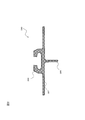
- a seat track having a cross-sectional shape in FIG. 2 is inserted in the aircraft floor along the longitudinal direction of the aircraft.
- the seat track 280 includes an underfloor structure portion 286 that serves as a structural material under the aircraft fuselage, a flat portion 287 that supports the floorboard, and a fitting portion 288 on the seat track side.
- the legs of the basic skeleton are fixed to the seat track by a track fitting member as shown in FIG.
- a track fitting member as shown in FIG.
- four track fitting members are disposed under the four front and rear leg portions of the basic skeleton of the seat unit, and are fixed to the two rows of seat tracks.
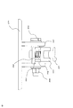
- FIG. 3 is an enlarged view around the track fitting member.
- the attachment 270 is also called a fitting bracket and is fixed to the seat track 280.
- the fitting portion 291 on the fitting side is fixed to the fitting portion 288 on the seat track side.
- the track fitting member 290 is provided with a bolt 294 and a nut 295 for fixing the fixture 270 to the fixture 270 by pressing the plunger 293 downward by a vertical spring 292 to take a load before and after the machine body. Further, a right cushioning material 297 and a left cushioning material 298 are attached between the track fitting member 290 and the fixture 270. The right-side cushioning material 297 and the left-side cushioning material 298 are provided with holes through which the male screw portions of the bolts 294 pass.
- various seat parts are attached to the basic skeleton fixed to the aircraft body. That is, as shown in the example of FIG. 1, the right shell 210 and the right armrest 310 are attached to the right side of the seat unit in the direction from the basic skeleton to the passage side.
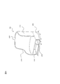
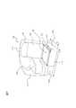
- FIG. 4 is a perspective view of the structure for the seat unit according to the first embodiment as viewed from the front.
- the structure for the seat unit (hereinafter sometimes referred to as “shell 20”) has a shell structure in which the lower structure and the upper shell are combined, and defines the outermost shell of the seat unit.
- the seat unit structure can support the seat in the innermost region of the outermost shell, and is fixed to the aircraft body at the bottom.
- the shell 20 is obtained by adding an upper shell composed of a right shell 210, a rear shell 220, and a left shell 230 as separate members above a seat base 240 that is a lower structure of the seat unit. is there.
- the shell 20 is connected and fixed to the aircraft at the bottom surface of the seat base 240.
- the seat base 240 which is the lower structure of the seat unit, is formed into a hollow box shape using integrally formed members.
- the integrally formed member specifically includes a thermoplastic resin such as polyetherimide and polyetherketone ketone, a thermosetting resin capable of appropriately controlling flammability, carbon graphite fiber, and glass. It is a member formed from a composite material such as a fiber or an aramid fiber, and can include a core material such as a foam or a honeycomb. Such an integrally formed composite member can form a strong three-dimensional shape without using connecting parts such as bolts and nuts. Moreover, since it is formed of the composite material as described above, it is possible to significantly reduce the number of places where rust prevention treatment is performed, compared to existing metal structural members.
- the hollow box structure means a cylindrical shape, and is a so-called monocoque structure. Therefore, the seat base 240 can support the load of the seat, the passenger, and the equipment (such as the reading lamp 360) used by the passenger.
- the hollow region 242 of the seat base 240 is rectangular when viewed from the front of the seat, but may be a quadrilateral such as a trapezoid. Further, the thickness of the members constituting the seat base 240, that is, the seat lower structure is about 10 mm to 15 mm.
- a seat base 240 there is no concept of a columnar support body, that is, a leg portion that supports the foot of one seat, which is restricted by the position of the seat track on the airframe side. For this reason, a common structure can be taken for seats of various sizes and shapes regardless of the shape of the upper structure of the seat. In addition, the mounting of electrical equipment and the wiring layout associated therewith are not restricted by the position of the legs, so that the degree of freedom in design can be expanded and shared.
- a partition member 250 can be disposed in the hollow region 242. Since the seat base 240 has a hollow monocoque structure, the partition member 250 (sometimes referred to as a partition plate) does not need to support the load of passengers or the like, and can move freely within the hollow region 242.
- the structure for the seat unit defines the outermost shell of the seat unit, and also defines the width of the passage adjacent to the seat unit. Therefore, as a requirement for the passage width, when a passage width in the vicinity of the height close to the floor is set wide, an upper portion made up of the right shell 210, the rear shell 220, and the left shell 230 on the seat base 240.
- the shell may be designed without protruding from the seat base 240.
- the maximum width dimension W and the maximum depth dimension D of the shell 20 coincide with the maximum width dimension and the maximum depth dimension of the seat base 240.
- the maximum width dimension of the upper shell is set larger than the maximum width dimension of the seat base 240. Also good. However, in this case, it should be noted that the maximum width dimension W and the maximum depth dimension D of the shell 20 do not match the maximum width dimension and the maximum depth dimension of the seat base 240.
- the upper shell shown in FIG. 4 shows an example in the case of business class or first class, and is configured as a side shell for ensuring privacy so that the line of sight of sitting passengers is blocked.
- the right shell 210 and the left shell 230 are provided at a height of about an armrest.
- FIG. 5 is a perspective view of the shell structure according to the first embodiment as viewed obliquely from the front, and shows a state before the seat 10 is attached.
- An upper seat support 160 for supporting the upper seat 120 of the seat 10 is disposed on the seat base 240.
- a storage box 330 serving as a console and a rear seat leg space is disposed on the right side of the upper seat support.
- a local reinforcing member 170 can be further disposed on the upper surface of the seat base 240 on the portion where the seat 10 is mounted.
- the storage box 330 and the reinforcing member 170 are disposed inside the shell structure, they are all disposed in the area inside the shell 20.
- FIG. 6 is a perspective view of an example of a seat seat used in the first embodiment when viewed obliquely from the front.
- the seat 10 is a lower seat 110 on which a passenger sits, an upper seat 120 on which the back is placed, a pillow-like portion on the upper portion of the backrest, a headrest 130 on which a head is rested and a neck is rested, and a calf on which a leg is placed
- a legrest 140 that reduces fatigue such as the above is provided.
- the seat reclining mechanism 180 is a mechanism that tilts the upper seat 120 backward.
- the foot reclining mechanism 190 is a mechanism that rotates the legrest 140 so as to lift up near the surface of the lower seat 110.
- FIG. 7 is a perspective view of a form in which the seat 10 described with reference to FIG. 7 is placed on the shell 20 described with reference to FIG.
- the depth dimension of the seat unit 1 is larger than the maximum depth dimension D of the shell 20 because the legrest 140 protrudes forward from the shell 20.
- the front of the seat unit 1 is a space for placing the passenger's legs, and is not stipulated by laws and regulations like the width of the passage between the seats.
- the width dimension of the seat unit 1 is not different from the maximum width dimension W of the shell 20 because all seat parts are arranged in the inner region in the width direction of the shell 20. That is, even after all seat parts are installed on the shell 20 in the aircraft, the width dimension of the seat unit 1 is fixed at the maximum width dimension W of the shell 20 and changes depending on the seat parts attached. There is nothing.
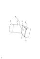
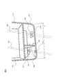
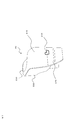
- FIG. 8 is a perspective view of the seat base, which is the lower structure of the seat unit according to the first embodiment, viewed obliquely from the rear.
- the shell 20 omits the back side shell 220 and illustrates the right side shell 210 and the left side shell 230 for the sake of convenience in describing a seat track described later.
- the first seat track 282 and the second seat track 284 constitute a pair of seat tracks and extend on the floor surface in the longitudinal direction of the aircraft body.
- the bottom of the seat unit 1 (the bottom of the seat base 240 in FIG. 8) is fixed to a pair of seat tracks, so that the seat unit 1 is attached to the aircraft body and passes a predetermined dynamic load test.
- FIG. 8 shows a state in which the seat base 240 is disposed slightly to the left with respect to the longitudinal direction of the aircraft body. For this reason, the seat base 240 does not face the first seat track 282 and the second seat track 284, and faces slightly to the left.
- the seat base 240 is fixed to three attachments for attachment to the aircraft body via three attachment blocks. Since the seat base 240 has a monocoque structure and does not have columnar legs, a mounting block is provided at the bottom of the seat base 240 to reinforce the connection between the fixture and the seat base 240.
- the mounting block is preferably made of metal, but the material is not limited as long as it is a reinforcing block.
- the first mounting block 262 is disposed in front of the bottom of the seat base 240, and the second mounting block 264 is disposed behind the first mounting block 262. .
- the third mounting block 266 is disposed on the right side.
- a mounting tool for the seat track is arranged (the mounting tool is indicated by a solid line). That is, the first attachment 272 is disposed below the first attachment block 262 and attached to the first seat track 282.
- the second fixture 274 is disposed below the second fixture block 264 and is attached to the first seat track 282 at a point spaced from the first fixture 272.
- the third fixture 276 is disposed below the third fixture block 266 and is a second seat track 284 between the first fixture 272 and the second fixture 274. It is attached to the corresponding part. Desirably, it is attached between the first attachment 272 and the second attachment 274 at substantially the center of the corresponding portion.
- FIG. 9 is an enlarged view of the vicinity of the bottom of the seat base 240 according to the first embodiment.
- the bottom of the seat base 240 has a honeycomb structure 248 between the inner surface 244 on the hollow region 242 side and the outer surface 246 on the opposite side.
- a mounting block 260 is disposed in the honeycomb structure 248.
- the mounting block 260 and the mounting tool 270 are fixed by bolts and nuts.
- the material of the inner surface 244 and the outer surface 246 is, for example, a composite fiber made of resin and fiber.
- the material of the honeycomb structure 248 is, for example, a composite fiber made of incombustible paper and phenol resin.
- the thickness of the attachment block 260 where the attachment 270 is disposed below is thin.
- the thickness of the bottom portion of the seat base 240 where the fixture 270 is disposed is similarly thin.
- the seat base 240 can be attached in a manner that does not face the seat track.
- the degree of freedom of seat arrangement in the cabin can be greatly improved.
- the first seat track 282 and the second seat track 284 extend on the longitudinal floor of the aircraft fuselage. Then, if the inclination angle of the seat base 240 with respect to the seat tracks 282 and 284 and the maximum width dimension W of the seat base 240 are used, the vertical direction of the seat tracks 282 and 284 (that is, the lateral direction perpendicular to the longitudinal direction of the aircraft) The size of the occupied width of all seat bases 240 can be calculated uniquely. This maximum occupied dimension (hereinafter referred to as “corrected dimension”) is represented by W ′ (not shown).
- FIG. 10 is a diagram for explaining an interval between seat bases in the first embodiment. From the maximum width dimension Wa of the seat base 240a, as described with reference to FIG. 8, the maximum occupied dimension with respect to the vertical direction of the seat tracks 282a and 284a is calculated to obtain a corrected dimension Wa ′ (not shown). Similarly, a corrected dimension Wb '(not shown) is obtained from the maximum width dimension Wb of the seat base 240b.
- the dimension W1 between the seat tracks (between 284a and 282b) inside the two seat bases is obtained from the structural design document of the airframe to which the seat base is attached. If the measurement directions of the corrected dimension Wa ′ and the corrected dimension Wb ′ are included in the direction defining the outermost shell of the seat unit, this W1, the corrected dimensions Wa ′ (not shown), Wb ′ ( (Not shown) and the positional relationship between the inner seat tracks 284a and 282b and the fixtures 272b, 274b and 276a fixed thereto, the distance W2 between the two seat bases, that is, the distance between the two seat units can be obtained. it can.
- This W2 is the width between the seats on the corresponding aisle side, and it is sufficient if it is equal to or larger than the dimension (for example, 51 cm) defined by law. If this calculation work is calculated from the front row seat to the last seat of the aircraft body, and the width between all the seats on the aisle side is greater than the legally stipulated size, there is no problem become.
- the structure for the seat unit used in the first embodiment includes a thermoplastic resin such as polyetherimide and polyetherketone ketone, a thermosetting resin capable of appropriately controlling flammability, carbon graphite fiber, and glass fiber.
- a member formed of a composite material such as an aramid fiber is combined with a core material such as a foam or a honeycomb as necessary, and is integrally formed.
- a seat unit there are two methods for attaching such a seat unit to the aircraft body.
- One is a method in which seat parts such as a seat seat are attached to a structure for a seat unit, and the almost completed seat unit is attached to an aircraft body.
- Another attachment method is a method of attaching a seat component such as a seat seat after attaching a structure such as a seat unit to an aircraft body.
- the seat unit structure (shell 20) is connected and fixed to the aircraft at the bottom surface of the seat base 240 and defines the outermost shell of the seat unit. Even if the parts are attached, this does not increase the lateral width on the passage side. For this reason, it is possible to determine the passage width before the seat unit is attached to the aircraft body. Further, even if the seat part is attached after the seat unit structure is connected and fixed to the aircraft, the predetermined passage width does not change, and the seat part attachment is not performed again.
- the distance between the seat unit and the window side can be determined in advance before the seat unit is attached to the aircraft body.
- the seat unit can be attached with a large degree of freedom without being affected by the position of the seat track.
- the angle at which the seat unit is attached to the seat track and the passage width that can be secured by this can be easily determined, it is easy to design the seat arrangement in the aircraft. It can be carried out.
- the manufacturing / installation process of the structure for seat units and the manufacturing / installation process of seat components including seats are completely separated and performed by separate operators in separate processes. It becomes possible.
- the seat manufacturer can easily perform test certification relating to the seat base, leading to a shortened development period.
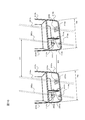
- FIG. 11 shows the structure (shell 20) of the seat unit described in the first embodiment in which the seat base 240 and the upper shell are integrally molded.
- the points are the same as in the first embodiment except that the seat base 240 and the upper shell are integrally molded.
- the seat base 240 and the upper shell are integrally molded together to realize a monocoque structure.
- the maximum width dimension W and the composite material used for the integrally molded member are the same as those in the first embodiment.
- the seat base and the upper shell are integrated, the strength of the entire seat can be improved. In addition, there is an effect that the mounting operation can be simplified.
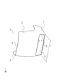
- FIG. 12 is a perspective view showing the structure (shell 20) of the seat unit with decoration.
- the shell 20 protects a protective cover 410 that protects the shell from the top surface to both sides, and the shell end surface.
- An end surface cover 420 is provided. That is, the buffer / decorative member (buffer and / or decorative member) is provided on the outer peripheral surface of the structure for the seat unit.
- the protective cover 410 is made of a soft material such as rubber or sponge so that when the passenger or flight attendant walks along the passage, the protective cover 410 is made of a soft thermoplastic resin such as rubber or sponge. Protects against direct contact with thermosetting resins, composite materials such as carbon graphite.
- the end surface cover 420 is for preventing a cart carrying food from coming into direct contact with the hard material constituting the shell 20 and covers not only the right shell 210 but also the lower end of the left shell 230. Yes.
- the protective cover 410 and the end surface cover 420 define the maximum width dimension outermost shell of the seat unit from the seat unit.
- the protective cover 410 and the end surface cover 420 also have a function of decorating the shell 20 that is integrally formed of a composite material.
- the shell 20 may be directly painted and covered with the transparent protective cover 410 and the decorative cover 420 on the end face.
- a display may be installed on the back side shell 220.
- a container, an outlet, a makeup mirror, etc. used by a person sitting in the back seat may be arranged.
- the third embodiment has the same effect as the first embodiment, and further prevents passengers, cabin crew, carts, etc. from directly touching the hard material constituting the shell 20. It has the effect.
- the object of the present invention is not limited to the aircraft, but can be applied to various mobile seats other than aircraft.
- Various modifications are included.
- trains, long-distance buses, and other types of vehicles and vehicles, such as water transportation, including passenger ships, ferries, and hovercraft, may be used as appropriate.
Landscapes
- Engineering & Computer Science (AREA)
- Aviation & Aerospace Engineering (AREA)
- Transportation (AREA)
- Mechanical Engineering (AREA)
- Seats For Vehicles (AREA)
Priority Applications (3)
| Application Number | Priority Date | Filing Date | Title |
|---|---|---|---|
| EP17904531.5A EP3608161B1 (en) | 2017-04-03 | 2017-12-18 | Structure for seat unit, seat unit, and attachment method thereof |
| US16/500,255 US11325711B2 (en) | 2017-04-03 | 2017-12-18 | Seat unit structure, seat unit, and attachment method thereof |
| SG11201908811U SG11201908811UA (en) | 2017-04-03 | 2017-12-18 | Seat unit structure, seat unit, and attachment method thereof |
Applications Claiming Priority (2)
| Application Number | Priority Date | Filing Date | Title |
|---|---|---|---|
| JP2017-073604 | 2017-04-03 | ||
| JP2017073604A JP7043180B2 (ja) | 2017-04-03 | 2017-04-03 | 座席ユニット用の構造体、座席ユニット及びその取付け方法 |
Publications (1)
| Publication Number | Publication Date |
|---|---|
| WO2018185979A1 true WO2018185979A1 (ja) | 2018-10-11 |
Family
ID=63712423
Family Applications (1)
| Application Number | Title | Priority Date | Filing Date |
|---|---|---|---|
| PCT/JP2017/045275 Ceased WO2018185979A1 (ja) | 2017-04-03 | 2017-12-18 | 座席ユニット用の構造体、座席ユニット及びその取付け方法 |
Country Status (5)
| Country | Link |
|---|---|
| US (1) | US11325711B2 (enExample) |
| EP (1) | EP3608161B1 (enExample) |
| JP (1) | JP7043180B2 (enExample) |
| SG (1) | SG11201908811UA (enExample) |
| WO (1) | WO2018185979A1 (enExample) |
Cited By (2)
| Publication number | Priority date | Publication date | Assignee | Title |
|---|---|---|---|---|
| US11235880B2 (en) * | 2017-04-03 | 2022-02-01 | Jamco Corporation | Rear side shell structure and seat unit |
| US11325711B2 (en) * | 2017-04-03 | 2022-05-10 | Jamco Corporation | Seat unit structure, seat unit, and attachment method thereof |
Families Citing this family (5)
| Publication number | Priority date | Publication date | Assignee | Title |
|---|---|---|---|---|
| JP6971608B2 (ja) * | 2017-04-03 | 2021-11-24 | 株式会社ジャムコ | 座席ユニット及びその下部構造体 |
| WO2019239204A1 (en) * | 2018-06-13 | 2019-12-19 | Safran Seats Usa Llc | Lightweight passenger privacy screen |
| USD1020327S1 (en) * | 2019-03-29 | 2024-04-02 | Safran Seats | Cabinet for seat |
| US20220332421A1 (en) * | 2021-04-16 | 2022-10-20 | B/E Aerospace, Inc. | Aircraft interior structure including improved bassinet provisions |
| EP4484286A1 (en) * | 2023-06-28 | 2025-01-01 | Safran Seats | Base unit |
Citations (5)
| Publication number | Priority date | Publication date | Assignee | Title |
|---|---|---|---|---|
| JPH1080341A (ja) * | 1996-08-22 | 1998-03-31 | Britax Rumbold Ltd | 乗物用シート |
| JP2004537459A (ja) * | 2001-08-09 | 2004-12-16 | ヴァージン アトランティック エアウェイズ リミテッド | 乗物用の座席システムおよび旅客収容設備ユニット |
| US20060170261A1 (en) * | 2004-12-22 | 2006-08-03 | Airbus Deutschland Gmbh | Passenger seat unit, in particular for commercial aircraft |
| JP2007524542A (ja) * | 2004-02-18 | 2007-08-30 | リーダーン インヴェストメンツ リミテッド | 航空機の座席ユニットと座席セット |
| JP2010527835A (ja) | 2007-05-22 | 2010-08-19 | ザ・ボーイング・カンパニー | 航空機のモジュラー式乗客席 |
Family Cites Families (15)
| Publication number | Priority date | Publication date | Assignee | Title |
|---|---|---|---|---|
| WO2015006313A2 (en) * | 2013-07-08 | 2015-01-15 | Arjuna Indraeswaran Rajasingham | Vehicle occupant support |
| US7021596B2 (en) * | 2004-02-11 | 2006-04-04 | Goodrich Corporation | Aircraft seat floor track quick release fitting |
| DE102004050082B4 (de) * | 2004-10-14 | 2010-01-07 | Airbus Deutschland Gmbh | Passagiersitz mit Gepäckfach |
| GB0426527D0 (en) | 2004-12-02 | 2005-01-05 | James Park Associates Ltd | Aircraft seat supporting structure |
| US20080088166A1 (en) * | 2006-10-16 | 2008-04-17 | Gardiner Richard J | Aircraft seat |
| GB2469180B8 (en) | 2009-03-23 | 2016-06-08 | Air New Zealand Ltd | Vehicle seating arrangement |
| US8231097B2 (en) * | 2009-09-11 | 2012-07-31 | Ami Industries, Inc. | Aircraft equipment support |
| EP2718180B1 (en) | 2011-06-07 | 2018-02-28 | Composite Helicopters International Holdings Limited | A helicopter |
| US9056570B2 (en) * | 2013-02-27 | 2015-06-16 | The Boeing Company | Variable thermal resistance device for vehicular seats |
| US11208213B2 (en) * | 2017-03-30 | 2021-12-28 | The Boeing Company | Integrated aircraft fuselage and load-bearing structural base for aircraft seats |
| JP7043180B2 (ja) * | 2017-04-03 | 2022-03-29 | 株式会社ジャムコ | 座席ユニット用の構造体、座席ユニット及びその取付け方法 |
| JP6971608B2 (ja) * | 2017-04-03 | 2021-11-24 | 株式会社ジャムコ | 座席ユニット及びその下部構造体 |
| US11279489B2 (en) * | 2017-10-26 | 2022-03-22 | Jing Zheng | Lie-flat passenger seat configurations for transportation |
| DE102018115776B4 (de) * | 2018-06-29 | 2023-12-21 | Airbus Operations Gmbh | Sitzgestellbefestigungsbaugruppe, Sitzgestell, Fahrzeugabschnitt und Fahrzeug mit einer Sitzgestellbefestigungsbaugruppe |
| US10829225B2 (en) * | 2018-12-11 | 2020-11-10 | Ami Industries, Inc. | Track fitting with quick release lock for aircraft seating |
-
2017
- 2017-04-03 JP JP2017073604A patent/JP7043180B2/ja active Active
- 2017-12-18 EP EP17904531.5A patent/EP3608161B1/en not_active Not-in-force
- 2017-12-18 SG SG11201908811U patent/SG11201908811UA/en unknown
- 2017-12-18 WO PCT/JP2017/045275 patent/WO2018185979A1/ja not_active Ceased
- 2017-12-18 US US16/500,255 patent/US11325711B2/en active Active
Patent Citations (5)
| Publication number | Priority date | Publication date | Assignee | Title |
|---|---|---|---|---|
| JPH1080341A (ja) * | 1996-08-22 | 1998-03-31 | Britax Rumbold Ltd | 乗物用シート |
| JP2004537459A (ja) * | 2001-08-09 | 2004-12-16 | ヴァージン アトランティック エアウェイズ リミテッド | 乗物用の座席システムおよび旅客収容設備ユニット |
| JP2007524542A (ja) * | 2004-02-18 | 2007-08-30 | リーダーン インヴェストメンツ リミテッド | 航空機の座席ユニットと座席セット |
| US20060170261A1 (en) * | 2004-12-22 | 2006-08-03 | Airbus Deutschland Gmbh | Passenger seat unit, in particular for commercial aircraft |
| JP2010527835A (ja) | 2007-05-22 | 2010-08-19 | ザ・ボーイング・カンパニー | 航空機のモジュラー式乗客席 |
Non-Patent Citations (1)
| Title |
|---|
| See also references of EP3608161A4 |
Cited By (2)
| Publication number | Priority date | Publication date | Assignee | Title |
|---|---|---|---|---|
| US11235880B2 (en) * | 2017-04-03 | 2022-02-01 | Jamco Corporation | Rear side shell structure and seat unit |
| US11325711B2 (en) * | 2017-04-03 | 2022-05-10 | Jamco Corporation | Seat unit structure, seat unit, and attachment method thereof |
Also Published As
| Publication number | Publication date |
|---|---|
| US11325711B2 (en) | 2022-05-10 |
| JP7043180B2 (ja) | 2022-03-29 |
| JP2018176770A (ja) | 2018-11-15 |
| US20210114735A1 (en) | 2021-04-22 |
| SG11201908811UA (en) | 2019-10-30 |
| EP3608161A1 (en) | 2020-02-12 |
| EP3608161A4 (en) | 2021-01-06 |
| EP3608161B1 (en) | 2022-08-03 |
Similar Documents
| Publication | Publication Date | Title |
|---|---|---|
| JP7043180B2 (ja) | 座席ユニット用の構造体、座席ユニット及びその取付け方法 | |
| JP6971608B2 (ja) | 座席ユニット及びその下部構造体 | |
| CN104520187B (zh) | 可变换成双层床的座椅装置 | |
| US10953987B2 (en) | Aircraft interior configuration with flexible use space | |
| JP2010527835A (ja) | 航空機のモジュラー式乗客席 | |
| JP4999218B2 (ja) | プライバシーおよび支持装置 | |
| US11235880B2 (en) | Rear side shell structure and seat unit | |
| CN115402516A (zh) | 座椅组件和乘客座椅装置 | |
| CN113165747B (zh) | 用于客运交通工具的商务舱座椅 | |
| JP2005219636A (ja) | 航空機、移動体、移動体に対する座席の配置方法 | |
| IT201800002320U1 (it) | Sedile per veicoli. | |
| CN102218996A (zh) | 房车座椅及安全带装置布置结构 | |
| WO2018185981A1 (ja) | 座席ユニット及びその取付け方法 | |
| CN113226931A (zh) | 尤其用于飞机的座椅单元组件 | |
| EP4116194A1 (en) | Passenger seating positioned proximate to an aircraft interior structure | |
| US10994846B2 (en) | Functional unit in a passenger cabin, including a support unit and a passenger seat system | |
| JP7300035B2 (ja) | 座席ユニット及びその取付け方法 | |
| US11530044B2 (en) | Using foam for structural components of a seat assembly | |
| US12459651B2 (en) | Seat covers and methods for using seat covers | |
| CN202080154U (zh) | 房车座椅及安全带装置布置结构 | |
| US9174736B2 (en) | Air passenger seat having a frame |
Legal Events
| Date | Code | Title | Description |
|---|---|---|---|
| 121 | Ep: the epo has been informed by wipo that ep was designated in this application |
Ref document number: 17904531 Country of ref document: EP Kind code of ref document: A1 |
|
| NENP | Non-entry into the national phase |
Ref country code: DE |
|
| ENP | Entry into the national phase |
Ref document number: 2017904531 Country of ref document: EP Effective date: 20191104 |