WO2018181952A1 - ベルト接合装置 - Google Patents
ベルト接合装置 Download PDFInfo
- Publication number
- WO2018181952A1 WO2018181952A1 PCT/JP2018/013761 JP2018013761W WO2018181952A1 WO 2018181952 A1 WO2018181952 A1 WO 2018181952A1 JP 2018013761 W JP2018013761 W JP 2018013761W WO 2018181952 A1 WO2018181952 A1 WO 2018181952A1
- Authority
- WO
- WIPO (PCT)
- Prior art keywords
- belt
- clamp
- joining apparatus
- belt end
- lower mold
- Prior art date
- Legal status (The legal status is an assumption and is not a legal conclusion. Google has not performed a legal analysis and makes no representation as to the accuracy of the status listed.)
- Ceased
Links
Images









Classifications
-
- B—PERFORMING OPERATIONS; TRANSPORTING
- B29—WORKING OF PLASTICS; WORKING OF SUBSTANCES IN A PLASTIC STATE IN GENERAL
- B29C—SHAPING OR JOINING OF PLASTICS; SHAPING OF MATERIAL IN A PLASTIC STATE, NOT OTHERWISE PROVIDED FOR; AFTER-TREATMENT OF THE SHAPED PRODUCTS, e.g. REPAIRING
- B29C65/00—Joining or sealing of preformed parts, e.g. welding of plastics materials; Apparatus therefor
- B29C65/02—Joining or sealing of preformed parts, e.g. welding of plastics materials; Apparatus therefor by heating, with or without pressure
- B29C65/18—Joining or sealing of preformed parts, e.g. welding of plastics materials; Apparatus therefor by heating, with or without pressure using heated tools
- B29C65/20—Joining or sealing of preformed parts, e.g. welding of plastics materials; Apparatus therefor by heating, with or without pressure using heated tools with direct contact, e.g. using "mirror"
-
- F—MECHANICAL ENGINEERING; LIGHTING; HEATING; WEAPONS; BLASTING
- F16—ENGINEERING ELEMENTS AND UNITS; GENERAL MEASURES FOR PRODUCING AND MAINTAINING EFFECTIVE FUNCTIONING OF MACHINES OR INSTALLATIONS; THERMAL INSULATION IN GENERAL
- F16G—BELTS, CABLES, OR ROPES, PREDOMINANTLY USED FOR DRIVING PURPOSES; CHAINS; FITTINGS PREDOMINANTLY USED THEREFOR
- F16G3/00—Belt fastenings, e.g. for conveyor belts
- F16G3/10—Joining belts by sewing, sticking, vulcanising, or the like; Constructional adaptations of the belt ends for this purpose
Definitions
- the present invention relates to a belt joining device, and more particularly to a device for joining belt ends.
- a belt joining device in which a heater and a press are integrated is disclosed as a means for joining a transmission and a transport belt endlessly using a thermoplastic resin as a main material (for example, Patent Document 1).
- a thermoplastic resin as a main material
- both ends of the belt are set between a pair of heating presses, and the both ends of the belt are fused and integrated by the heating press, and then solidified by cooling.
- Patent Document 1 since the heater and the press are integrated, there is a problem that it is difficult to downsize the belt joining apparatus.
- a small belt joining apparatus is desired. For example, when replacing a belt used in a conveyor device of an automatic ticket gate, it is necessary to remove the conveyor device from the automatic ticket gate once in order to secure a work space for applying a tension to the belt and joining the belt. If it does so, since it is necessary to attach a conveying apparatus to an automatic ticket gate again after belt replacement, an extra work time will be required and work will become complicated.
- An object of the present invention is to provide a belt joining device capable of easily joining a belt even in a narrow place.
- a belt joining apparatus includes a belt including a first belt end, a holding body that holds both ends of the second belt end in contact with each other, and a pressure body that pressurizes the both ends in the thickness direction.
- the holding body includes a lower mold on which the first belt end and the second belt end are placed on an upper surface, and upper surfaces of the first belt end and the second belt end.
- the belt pulling mechanism is provided between the lower mold and the clamp body, the belt end portions can be brought into contact with each other in a tensioned state so that the belt can be easily held even in a narrow place. Can be joined.
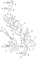
- FIG. 1 It is a perspective view which shows the belt joining apparatus which concerns on 1st Embodiment. It is an exploded perspective view of the belt joining device concerning a 1st embodiment. It is a longitudinal cross-sectional view of the lower mold
- a belt joining apparatus 10A shown in FIG. 1 includes a holding body 12 and a pressurizing body 14, and makes a belt-like belt 13 endless.
- the holding body 12 and the pressurizing body 14 are formed of a metal such as iron, aluminum, and stainless steel, or a resin having heat resistance.
- the holding body 12 holds the first belt end portion 16 and the second belt end portion 18 in contact with each other.
- the pressurizing body 14 pressurizes both end portions of the first belt end portion 16 and the second belt end portion 18 in the thickness direction.
- the X direction is the belt running direction
- the Y direction is the belt width direction
- the Z direction is the belt thickness direction.
- the belt 13 is a thermosetting resin belt main body 15, a first joining portion 17 provided at a first belt end 16 that is one end of the belt main body 15, and the other end. And a second joint 19 provided at the second belt end 18.
- the 1st junction part 17 and the 2nd junction part 19 are formed with thermoplastic resins, for example, a urethane elastomer, a polyamide elastomer, a polyester elastomer, a polyvinyl chloride elastomer, and a polyolefin elastomer.
- the holding body 12 includes an upper mold 20, a lower mold 22, two clamp bodies 24 that are detachably integrated with the lower mold 22, and two belt clamps 26.
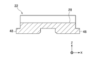
- the lower mold 22 has a guide groove 28 and two convex portions 48.
- the guide groove 28 is a groove provided on the upper surface of the lower die 22 and parallel to the running direction of the belt 13, and the first belt end 16 and the second belt end 18, whose ends are butted together, are viewed from below. support.
- the width and depth of the guide groove 28 are formed in accordance with the width and thickness of the belt 13 to be joined.
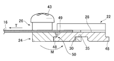
- the convex portions 48 are respectively provided at the centers of both side portions on the running direction side of the belt 13. As shown in FIG. 3, the convex portion 48 of the lower mold 22 is provided on the lower surface of the lower mold 22, and the tip protrudes in the running direction of the belt 13.
- the upper mold 20 is disposed above both ends of the first belt end portion 16 and the second belt end portion 18 that are abutted (FIG. 2).
- the upper mold 20 incorporates a heater and is connected to the connector 47 through wiring.
- a heating wire heater or a ceramic heater can be used. Further, the temperature can be easily controlled by using a PTC (Positive ⁇ ⁇ ⁇ Coefficient) heater as the heater.
- the width of the upper mold 20 is preferably smaller than that of the guide groove 28 so that no gap is generated between the upper mold 20 and the guide groove 28.
- the clamp body 24 is a rectangular plate material, and has a hole 30 and a groove 32.
- the clamp main body 24 includes a first main body 33 having a first upper surface 31 and a second main body 37 having a second upper surface 35 lower than the first upper surface 31.
- the groove 32 is provided on the first upper surface 31, is parallel to the belt traveling direction, and has the same width as the guide groove 28.
- the depth of the groove 32 is preferably the same as that of the guide groove 28.
- the hole 30 penetrates the second main body 37 in the thickness direction, and the convex portion 48 of the lower mold 22 is inserted therein.
- the first main body 33 has female threads 36 on both sides of the groove 32.
- the belt clamp 26 is a rectangular plate material, and is formed with a prepared hole 40 into which a clamp screw 43 is inserted and a notch hole 42.
- the notch hole 42 is notched on one side of the belt clamp 26 in the longitudinal direction.
- the clamp screw 43 can be inserted into the notch hole 42 from the width direction of the belt clamp 26.
- the clamp screw 43 inserted into the prepared hole 40 and the cutout hole 42 is inserted into the female screw 36 in a state where the first belt end portion 16 or the second belt end portion 18 is sandwiched between the surface of the clamp body 24 and the belt clamp 26.
- the clamp body 24 is fixed to the clamp body 24.
- the pressure body 14 has a frame portion 44 and a pressure screw 46.
- the frame part 44 has a C-shaped cross section, and has a plate-like upper end part and a lower end part divided into two parts.
- the frame portion 44 sandwiches the lower die 22 in the vertical direction so that the lower end portion is disposed on the lower surface of the lower die 22 and the upper end portion is disposed on the upper surface of the lower die 22.
- a female screw 45 for tightening the pressurizing screw 46 is formed substantially at the center of the upper end portion.
- the frame portion 44 presses the upper die 20 against the lower die 22 by a pressure screw 46 fastened to the female screw 45 with the lower die 22 sandwiched vertically.
- the clamp body 24 includes a first body 33 and a second body 37 that are integral with each other.
- the first main body 33 has a closing protrusion 50 that protrudes toward the hole 30.
- the closing protrusion 50 closes a part of the opening on the side farther from the tip of the second main body 37 of the hole 30.
- the surface 49 of the first main body 33 on the side in contact with the second main body 37 is inclined outward in the radial direction of the hole 30 from the lower end toward the upper end.
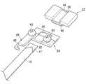
- the belt clamp 26 is temporarily fixed to the clamp body 24. That is, the clamp screw 43 is inserted into the prepared hole 40, and the clamp screw 43 is fastened to one female screw 36 of the clamp body 24 to be temporarily fixed. The clamp screw 43 is tightened and temporarily fixed to the other female screw 36 in a state where the clamp body 24 is not inserted (FIG. 5).
- the first belt end 16 is disposed in the groove 32 of the clamp body 24.
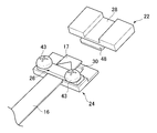
- the belt clamp 26 is rotated around the clamp screw 43, the belt clamp 26 is disposed above the first belt end portion 16, and the clamp screw 43 temporarily fixed to the other female screw 36 is formed in the notch hole 42. insert.
- each clamp screw 43 is tightened, and the first belt end portion 16 is fixed to the clamp body 24 by the belt clamp 26 and the clamp screw 43 (FIG. 6).
- the belt clamp 26 is temporarily fixed to the clamp main body 24 with one clamp screw 43, inserted into the other clamp screw 43 from the width direction, and fixed to the clamp main body 24, whereby the first belt end 16 is fixed.
- the work after the arrangement in the groove 32 can be simplified.
- the second upper surface 35 of the clamp body 24 is disposed on the lower surface side of the lower mold 22, and the tip of the convex portion 48 is inserted from the hole 30 to the lower side of the closing projection 50 (FIG. 7). Since the surface 49 of the first main body 33 on the side in contact with the second main body 37 is inclined, the tip of the convex portion 48 reaches the lower back of the closing protrusion 50.
- the clamp body 24 is rotated with the tip of the closing projection 50 as a fulcrum, and the second upper surface 35 is brought into contact with the lower surface of the lower mold 22 (FIG. 8).
- the convex portion 48 is inserted into the hole 30, and the clamp body 24 and the lower mold 22 are integrated.
- a contact portion between the closing protrusion 50 and the convex portion 48 is disposed below the first belt end portion 16.
- the second belt end 18 is similarly fixed to the clamp body 24 by another belt clamp 26 and a clamp screw 43 (FIG. 9).
- the clamp body 24 and the belt clamp 26 can be fixed without applying tension to the first belt end 16 and the second belt end 18.
- the position of the second belt end 18 for fixing the clamp body 24 is a position where a predetermined tension can be applied to the belt when the clamp body 24 is fixed to the lower mold 22.
- the clamp body 24 is pulled in the direction of the lower die 22 and integrated with the lower die 22, thereby holding the first belt end portion 16 and the second belt end portion 18 in contact with each other (FIG. 10).
- the upper mold 20 is disposed so as to cover the first belt end 16 and the second belt end 18 (FIG. 11).
- the frame portion 44 is arranged so as to sandwich the holding body 12 up and down.
- the upper end is disposed above the upper mold 20, and the lower end is disposed on both ends in the longitudinal direction of the lower mold 22.
- the pressure screw 46 By tightening the pressure screw 46, the first belt end 16 and the second belt end 18 are pressed in the thickness direction through the upper mold 20 (FIG. 1).
- the heater incorporated in the upper mold 20 is energized through the connector 47, and the first joint 17 and the second joint 19 are heated for a predetermined time. The heated first joint 17 and second joint 19 are melted.
- the energization to the heater is stopped and the melted portion is cooled, so that the first joint portion 17 and the second joint portion 19 are solidified to form a fused portion.
- the pressure screw 46 is loosened and the frame portion 44 is removed from the holding body 12. Further, the holder 12 is detached from the first belt end 16 and the second belt end 18 by loosening the clamp screw 43 and removing the belt clamp 26 from the clamp body 24. As described above, the first belt end portion 16 and the second belt end portion 18 can be joined.
- the belt joining apparatus 10A includes a belt pulling mechanism having a convex portion 48 of the lower mold 22 and a hole 30 of the clamp body 24, so that the belt end portions are brought into contact with each other in a tensioned state. Can do. Therefore, the belt joining apparatus 10A can easily join the belt even in a narrow place.
- the clamp body 24 has the closing protrusion 50, so that the clamp body 24 is firmly integrated with the lower mold 22 by the force T that pulls the belt 13. Therefore, the belt joining apparatus 10A can prevent the lower mold 22 and the clamp body 24 from being unexpectedly separated, and thus can improve the workability.
- the pressurizing body 14A includes a pair of levers, a fastener that connects the levers, and a spring that applies a force in a closing direction with respect to one of the fasteners.
- the pressing body 14A can pressurize the first belt end portion 16 and the second belt end portion 18 in the thickness direction through the upper mold 20 by sandwiching the holding body 12 with a lever.
- a belt joining apparatus 10 ⁇ / b> B shown in FIG. 13 includes a holding body 51 and a pressurizing body 54.
- the belt joining apparatus 10B is different from the first embodiment in that a heater is not built in the upper die and is provided on the lower surface of the lower die 52, and that one clamp body is provided.
- the holding body 51 includes a lower mold 52, an upper mold 53, one clamp body 58, and two belt clamps 60.
- the lower mold 52 has one convex portion 66.
- the convex portion 66 is provided at the center of one side portion on the belt running direction side.
- a heater 56 is provided on the lower surface of the lower mold 52.
- the clamp screw 62 is inserted into the prepared hole, the clamp screw 62 is fastened to one female screw of the lower mold 52, and one belt clamp 60 is temporarily fixed to the lower mold 52.
- the clamp screw 62 in a state where the clamp body 58 is not inserted is tightened and temporarily fixed to the other female screw (FIG. 15).
- the first belt end 16 is disposed in the guide groove 55 of the lower mold 52.
- the belt clamp 60 is rotated around the clamp screw 62 temporarily fixing the belt clamp 60, and the clamp screw 62 temporarily fixed to the other female screw is inserted into the notch hole 61.
- Each clamp screw 62 is tightened in a state where the belt clamp 60 is disposed on the upper side of the first belt end portion 16, and the first belt end portion 16 is fixed to the lower mold 52 by the belt clamp 60 and the clamp screw 62.
- the second belt end 18 is fixed to the clamp body 58 by the belt clamp 60 and the clamp screw 62 in the same procedure as in the first embodiment (FIG. 16).
- the second upper surface 59 of the clamp body 58 is disposed on the lower surface side of the lower mold 52, and the tip of the convex portion 66 is inserted below the closing projection (not shown), so that the clamp body 58 and the lower mold 52 are integrated.
- FIG. 17 the 1st belt end part 16 and the 2nd belt end part 18 have a finger joint provided with the layer of the thermoplastic resin.
- the upper mold 53 is disposed on the first belt end portion 16 and the second belt end portion 18 so as to be covered from above, and the frame portion 63 is disposed so as to sandwich the holding body 51 vertically.
- the pressure screw 64 By tightening the pressure screw 64, the first belt end 16 and the second belt end 18 are pressed in the thickness direction through the upper mold 53.
- the belt joining apparatus 10B of the present embodiment can obtain the same effects as those of the first embodiment by including the belt pulling mechanism.
- the heater 56 having a larger area can be used by arranging the heater 56 on the lower surface of the lower mold 52. Therefore, since the belt joining apparatus 10B can heat the first belt end 16 and the second belt end 18 in a wider range, the belt joining device 10B can be joined more reliably.
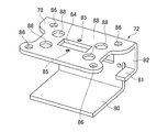
- the pressure body 70 includes a frame portion 72, an elastic portion 73 disposed between the frame portion 72 and the upper mold 53, and a cam mechanism 76 that presses the elastic portion 73 against the upper mold 53.
- the frame portion 72 has a substantially C-shaped cross section, a plate-like upper end portion 78, a lower end portion 80 arranged in parallel with the upper end portion 78, and one side of the upper end portion 78 and the lower end portion 80. And a back plate portion 82 for connecting the two. On both sides of the back plate portion 82, an intermediate portion 81 protruding in parallel with the upper end portion 78 is provided between the upper end portion 78 and the lower end portion 80.
- the upper end 78 has a rectangular through hole 84 in the center.
- Female screws 85 are provided at the upper end portions 78 on both sides in the width direction of the through hole 84.
- the upper end portion 78 is formed with a total of four relief holes 88 at the four corners so as to surround the through hole 84, and a total of four installation holes 86 at the four corners of the upper end portion 78.
- the elastic part 73 is supported on the lower surface of the upper end part 78 via the holding part 90.
- the holding unit 90 includes a holding plate 91 disposed in parallel with the upper end portion 78 and shafts 93 fixed to the four corners of the holding plate 91.
- the holding plate 91 is loaded with a return spring 94 on the shaft 93 inserted into the installation hole 86 and fixed on the tip end side of the shaft 93 so as not to come off from the shaft 93, so that the upper end portion 78 is fixed. It is supported so as to be movable in the thickness direction.
- the elastic portion 73 includes a push plate 92 disposed in parallel with the holding plate 91 and a coil spring 74 disposed between the holding plate 91 and the push plate 92.
- the push plate 92 is provided with shafts 95 projecting toward the holding plate 91 at four corners.
- the shaft 95 is loaded with a coil spring 74 and can be moved in the thickness direction relative to the holding plate 91 by screwing a nut 75 into the tip of the shaft 95 inserted into a hole (not shown) formed in the holding plate 91. It is supported by.
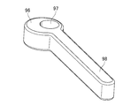
- the cam mechanism 76 includes a plate cam 96, a lever 98 formed integrally with the plate cam 96, and a shaft 100.
- the plate cam 96 has a disk shape and is provided with a hole 97 penetrating in the thickness direction at a position shifted from the center.
- the plate cam 96 is rotatably supported by inserting the shaft 100 spanned in the width direction of the through hole 84 into the hole 97, and is disposed in the through hole 84.
- the shaft 100 is fixed to the upper end portion 78 by screwing the bolt 102 into the female screw 85.
- the holding plate 91, the coil spring 74, and the push plate 92 are arranged in this order from the upper end 78 side between the upper mold 53 and the upper end 78, and the plate cam 96 is in contact with the holding plate 91.
- the cam mechanism 76 tilts the lever 98 about the shaft 100, so that the length of the plate cam 96 that protrudes downward from the upper end portion 78 is shifted by the amount that the center of the plate cam 96 is displaced from the center of the hole 97. You can change that.
- the lower end 80 is disposed with a gap between the lower surface 80 and the lower surface of the heater 56.
- the intermediate part 81 is in contact with the lower surface of the lower mold 52.
- the holding body 51 is positioned with respect to the depth direction of the frame portion 72 by an adjusting screw 104 screwed in the thickness direction of the back plate portion 82.
- the cam mechanism 76 can press the push plate 92 against the upper mold 53 as shown in FIG. . That is, when the plate cam 96 rotates and protrudes downward from the upper end portion 78, the holding plate 91 is pressed downward. When the return spring 94 contracts, the holding plate 91 moves downward so as to be separated from the upper end portion 78. As the holding plate 91 moves, the push plate 92 moves down until it comes into contact with the upper mold 53. The first belt end 16 and the second belt end 18 can be pressed in the thickness direction with a large force by the amount that the plate cam 96 protrudes downward from the upper end 78.
- the reaction force becomes larger than the restoring force of the coil spring 74, the coil spring 74 contracts accordingly.
- the belt joining apparatus 10 ⁇ / b> C can prevent the force with which the pressing plate 92 presses the upper mold 53 from being excessive due to the coil spring 74 contracting.
- the cam mechanism 76 is pressed against the upper mold 53 by the push plate 92 as shown in FIG. Can be released. That is, when the length of the plate cam 96 protruding downward from the upper end portion 78 is reduced by the rotation of the plate cam 96, the holding plate 91 moves toward the upper end portion 78 by the restoring force of the return spring 94. As the holding plate 91 moves, the push plate 92 moves away from the upper mold 53 and rises. The holding plate 91 can come into contact with the upper end portion 78 when the tip end of the shaft 95 passes through the escape hole 88.
- the first belt end 16 and the second belt end 18 are pressed in the thickness direction through the upper mold 53 by tilting and tilting the lever 98 to one side or the other side. It can be canceled.
- the elastic part 73 is not limited to the case where it has the push plate 92 and the coil spring 74.
- a rubber plate 110 may be used as the elastic part as in the belt joining apparatus 10D shown in FIG.
- the rubber plate 110 is directly fixed to the lower surface side of the holding plate 91, that is, the surface on the upper mold 53 side.
- the lever 98 by operating the lever 98, the first belt end 16 and the second belt end 18 can be pressurized in the thickness direction, or the pressure can be released.
- the frame part 112 can omit the escape hole 88 of the upper end part 78.
- the present invention is not limited to the above-described embodiment, and can be appropriately changed within the scope of the gist of the present invention.
- the 1st junction part 17 and the 2nd junction part 19 demonstrated the case where it joined to the belt main body 15 previously, this invention is not limited to this.
- the joining portion may be a separate body from the belt main body, and may be disposed between the first belt end portion and the second belt end portion fixed to the holding body.
- a columnar heater may be used as the heater.
Landscapes
- Engineering & Computer Science (AREA)
- General Engineering & Computer Science (AREA)
- Mechanical Engineering (AREA)
- Lining Or Joining Of Plastics Or The Like (AREA)
Abstract
狭い場所でもベルトを容易に接合することができるベルト接合装置を提供する。第1ベルト端部16と、第2ベルト端部18の両端部を突き合わせて保持する保持体12と、前記両端部16,18を厚さ方向に加圧する加圧体14と備えるベルト接合装置10Aであって、前記保持体12は、前記第1ベルト端部16及び前記第2ベルト端部18が上面に載置される下型22と、前記第1ベルト端部16及び前記第2ベルト端部18の上面に配置される上型20と、ベルトクランプ26と、前記第1ベルト端部16又は第2ベルト端部18を間に挟んで前記ベルトクランプ26が着脱自在に固定される少なくとも1つのクランプ本体24と、前記第1ベルト端部16及び前記第2ベルト端部18を加熱するヒータとを有し、前記クランプ本体24と前記下型22の間にベルト引寄せ機構を備える。
Description
本発明は、ベルト接合装置に関し、特にベルトの端部同士を接合する装置に関する。
熱可塑性樹脂を主材料とする伝動、搬送ベルトを無端状に接合する手段としては、加熱ヒータとプレスとが一体化されたベルト接合装置が開示されている(例えば、特許文献1)。上記ベルト接合装置は、ベルトの両端部を一対の加熱プレス間にセットし、当該加熱プレスによりベルトの両端部を融着して一体化し、その後冷却することにより固形化する。
しかしながら上記特許文献1の場合、加熱ヒータとプレスとが一体化されているので、ベルト接合装置を小型化することが困難であるという問題があった。ベルトが使用される現場においては、小型のベルト接合装置が望まれる。例えば自動改札機の搬送装置に使われているベルトを交換する際、ベルトに張力を与えて接合する作業スペースを確保するため、搬送装置を自動改札機から一旦取り外す必要がある。そうするとベルト交換後、搬送装置を再度自動改札機へ取り付ける必要があるので、余計に作業時間を要し、作業が煩雑になってしまう。
本発明は、狭い場所でもベルトを容易に接合することができるベルト接合装置を提供することを目的とする。
本発明に係るベルト接合装置は、第1ベルト端部と、第2ベルト端部の両端部を突き合わせて保持する保持体と、前記両端部を厚さ方向に加圧する加圧体とを備えるベルト接合装置であって、前記保持体は、前記第1ベルト端部及び前記第2ベルト端部が上面に載置される下型と、前記第1ベルト端部及び前記第2ベルト端部の上面に配置される上型と、ベルトクランプと、前記第1ベルト端部又は前記第2ベルト端部を間に挟んで前記ベルトクランプが着脱自在に固定される少なくとも1つのクランプ本体と、前記第1ベルト端部及び前記第2ベルト端部を加熱するヒータとを有し、前記クランプ本体と前記下型の間にベルト引寄せ機構を備える。
本発明によれば、下型とクランプ本体の間に、ベルト引き寄せ機構を備えることにより、張力を与えた状態でベルト端部同士を突き合わせて保持することができるので、狭い場所でもベルトを容易に接合することができる。
以下、図面を参照して本発明の実施形態について詳細に説明する。
1.第1実施形態
(全体構成)
図1に示すベルト接合装置10Aは、保持体12と、加圧体14とを備え、帯状のベルト13を無端状にする。保持体12及び加圧体14は、鉄、アルミニウム、ステンレスなどの金属や、耐熱性を有する樹脂で形成される。保持体12は、第1ベルト端部16と、第2ベルト端部18を突き合わせて保持する。加圧体14は、第1ベルト端部16及び第2ベルト端部18の両端部を厚さ方向に加圧する。なお、本図においてX方向をベルト走行方向、Y方向をベルトの幅方向、Z方向をベルトの厚さ方向とする。
(全体構成)
図1に示すベルト接合装置10Aは、保持体12と、加圧体14とを備え、帯状のベルト13を無端状にする。保持体12及び加圧体14は、鉄、アルミニウム、ステンレスなどの金属や、耐熱性を有する樹脂で形成される。保持体12は、第1ベルト端部16と、第2ベルト端部18を突き合わせて保持する。加圧体14は、第1ベルト端部16及び第2ベルト端部18の両端部を厚さ方向に加圧する。なお、本図においてX方向をベルト走行方向、Y方向をベルトの幅方向、Z方向をベルトの厚さ方向とする。
図2に示すように、ベルト13は、熱硬化性樹脂のベルト本体15と、当該ベルト本体15の一端である第1ベルト端部16に設けられた第1接合部17と、他端である第2ベルト端部18に設けられた第2接合部19とを備える。第1接合部17と、第2接合部19は、熱可塑性樹脂、例えば、ウレタンエラストマー、ポリアミドエラストマー、ポリエステルエラストマー、ポリ塩化ビニル系エラストマー、ポリオレフィン系エラストマーで形成されている。
保持体12は、上型20と、下型22と、下型22と着脱自在に一体化される2個のクランプ本体24と、2個のベルトクランプ26とを有する。下型22は、ガイド溝28と、2個の凸部48とを有する。ガイド溝28は、下型22の上面に設けられた、ベルト13の走行方向に平行な溝であり、端部同士が突き合わされた第1ベルト端部16及び第2ベルト端部18を下から支える。ガイド溝28の幅及び深さは、接合するベルト13の幅及び厚さに合わせて形成される。凸部48は、ベルト13の走行方向側の両側部の中央にそれぞれ設けられている。図3に示すように、下型22の凸部48は、下型22の下面に設けられ、先端がベルト13の走行方向に向かって突出している。
上型20は、突き合わされた第1ベルト端部16及び第2ベルト端部18の両端部の上側に、配置される(図2)。上型20は、ヒータが内蔵されており、配線を通じてコネクター47に接続されている。ヒータは、電熱線ヒータやセラミックヒータを用いることができる。またヒータとしてPTC(Positive Temperature Coefficient)ヒータを用いることにより、容易に温度制御をすることができる。上型20の幅長さは、ガイド溝28より小さく、上型20とガイド溝28の間に隙間が生じない程度が好ましい。
クランプ本体24は、矩形状の板材であって、穴30と、溝32とを有する。クランプ本体24は、第1上面31を有する第1本体33と、当該第1上面31より低い第2上面35を有する第2本体37とを備える。溝32は、第1上面31に設けられ、ベルト走行方向に平行であり、ガイド溝28と同じ幅を有する。クランプ本体24と下型22を一体化した場合、溝32の深さは、ガイド溝28と同じであるのが好ましい。穴30は、第2本体37を厚さ方向に貫通しており、下型22の凸部48が挿入される。第1本体33は、溝32の両側に雌ねじ36を有する。
ベルトクランプ26は、矩形状の板材であって、クランプねじ43が挿入される下穴40及び切欠き穴42が形成されている。切欠き穴42は、ベルトクランプ26の長手方向の一側面側が切り欠かれている。クランプねじ43は、切欠き穴42にベルトクランプ26の幅方向から挿入することができる。ベルトクランプ26は、クランプ本体24表面との間に第1ベルト端部16又は第2ベルト端部18を挟んだ状態で、下穴40及び切欠き穴42に挿入されたクランプねじ43を雌ねじ36に締め込むことによって、クランプ本体24に固定される。
加圧体14は、枠部44と、加圧ねじ46とを有する。枠部44は、断面がC形で、板状の上端部と、二股に分かれた下端部とを有する。枠部44は、下端部が下型22の下面、上端部が下型22の上面に配されるように、下型22を上下に挟む。上端部の略中央には、加圧ねじ46を締め込む雌ねじ45が形成されている。枠部44は、下型22を上下に挟んだ状態で、雌ねじ45に締め込んだ加圧ねじ46によって上型20を下型22へ押し付ける。
図4に示すように、クランプ本体24は、第1本体33と第2本体37が一体である。第1本体33は、穴30に向かって突出した閉塞突起50を有する。閉塞突起50は、穴30の第2本体37の先端から遠い側の、開口の一部を塞ぐ。第1本体33の第2本体37に接する側の表面49は、下端から上端に向かって、穴30の半径方向の外向きに傾斜している。
(ベルト接合装置の使用方法)
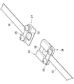
次に本実施形態に係るベルト接合装置10Aを用いたベルトの接合方法を説明する。まず、ベルトクランプ26をクランプ本体24に仮固定する。すなわち下穴40にクランプねじ43を挿入し、当該クランプねじ43をクランプ本体24の一方の雌ねじ36に締め込み、仮固定しておく。他方の雌ねじ36には、クランプ本体24が挿入されていない状態で、クランプねじ43を、締め込み仮固定しておく(図5)。
次に本実施形態に係るベルト接合装置10Aを用いたベルトの接合方法を説明する。まず、ベルトクランプ26をクランプ本体24に仮固定する。すなわち下穴40にクランプねじ43を挿入し、当該クランプねじ43をクランプ本体24の一方の雌ねじ36に締め込み、仮固定しておく。他方の雌ねじ36には、クランプ本体24が挿入されていない状態で、クランプねじ43を、締め込み仮固定しておく(図5)。
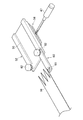
第1ベルト端部16をクランプ本体24の溝32に配置する。次いで、クランプねじ43を中心にベルトクランプ26を回転させて、当該第1ベルト端部16の上側にベルトクランプ26を配置し、他方の雌ねじ36に仮固定したクランプねじ43を切欠き穴42に挿入する。この状態でそれぞれのクランプねじ43を締め込み、第1ベルト端部16を、ベルトクランプ26及びクランプねじ43によってクランプ本体24に固定する(図6)。ベルトクランプ26は、一方のクランプねじ43でクランプ本体24に仮固定しておき、他方のクランプねじ43に幅方向から挿入して、クランプ本体24に固定することにより、第1ベルト端部16を溝32に配置した後の作業を簡略化することができる。
次いで、クランプ本体24の第2上面35を下型22の下面側に配置して、凸部48の先端を穴30から閉塞突起50の下側に挿入する(図7)。第1本体33の第2本体37に接する側の表面49が、傾斜していることにより、凸部48は、先端が閉塞突起50の下側奥まで到達する。
続いて閉塞突起50の先端を支点としてクランプ本体24を回転させ、第2上面35を下型22の下面に接触させる(図8)。上記のようにして、凸部48を穴30に挿入し、クランプ本体24と下型22を一体化する。閉塞突起50と凸部48の接触部分は、第1ベルト端部16の下側に配置される。
第1ベルト端部16に対し、引張方向の力Tが作用した場合、閉塞突起50と凸部48の接触部分には、反時計回りのモーメントMが作用する。閉塞突起50を支点として第2上面35は、下型22の下面に押し付けられ、凸部48と穴30が係合し、第1ベルト端部16に力Tが作用している限り、下型22とクランプ本体24は、一体化した状態で保持される。
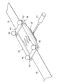
第2ベルト端部18も、同様にして、別のベルトクランプ26及びクランプねじ43によってクランプ本体24に固定する(図9)。クランプ本体24及びベルトクランプ26は、第1ベルト端部16及び第2ベルト端部18に対し張力を付与しない状態で固定することができる。なお、クランプ本体24を固定する第2ベルト端部18の位置は、クランプ本体24を下型22に固定した場合に、所定の張力をベルトに付与できる位置とする。
当該クランプ本体24を下型22の方向へ引張り、下型22と一体化することにより、第1ベルト端部16及び第2ベルト端部18を突き合わせた状態で保持する(図10)。
第2ベルト端部18側においても、ベルトに作用した張力によって、閉塞突起50と凸部48の接触部分に互いを押し付ける向きの力が作用し、下型22とクランプ本体24が一体化した状態で保持される。
次いで、上型20を、第1ベルト端部16及び第2ベルト端部18の上から被せるように配置する(図11)。
続いて保持体12を上下に挟むようにして枠部44を配置する。この場合、上端部は上型20の上方、下端部は下型22の長手方向両端側に配置される。加圧ねじ46を締め込むことによって、上型20を通じて第1ベルト端部16及び第2ベルト端部18を厚さ方向に加圧する(図1)。
この状態で、コネクター47を通じて上型20に内蔵されたヒータに通電し、第1接合部17及び第2接合部19を所定時間、加熱する。加熱された第1接合部17と第2接合部19は、溶融する。
所定時間経過後、ヒータへの通電を停止して、溶融した部分を冷却することにより、第1接合部17及び第2接合部19が固化し、融着部が形成される。冷却後、加圧ねじ46を緩め枠部44を保持体12から取り外す。さらにクランプねじ43を緩めてベルトクランプ26をクランプ本体24から取り外すことにより、保持体12を第1ベルト端部16及び第2ベルト端部18から取り外す。以上のようにして、第1ベルト端部16及び第2ベルト端部18を接合することができる。
本実施形態のベルト接合装置10Aは、下型22の凸部48、クランプ本体24の穴30を有するベルト引き寄せ機構を備えることにより、張力を与えた状態でベルト端部同士を突き合わせて保持することができる。したがってベルト接合装置10Aは、狭い場所でもベルトを容易に接合することができる。
またクランプ本体24は、閉塞突起50を有することにより、ベルト13を引っ張る力Tによって下型22と強固に一体化される。したがってベルト接合装置10Aは、下型22とクランプ本体24が不意に分離することを防止できるので、作業性をより向上することができる。
上記第1実施形態の場合、加圧体14が図2に示す枠部44を有する場合について説明したが、本発明はこれに限らない。例えば、図12に示す加圧体14Aを用いてもよい。加圧体14Aは、一対のレバーと、当該レバー同士を連結する留め具と、留め具を挟んで一方に対し閉じる方向に力を加えるばねとを備える。加圧体14Aは、レバーで保持体12を挟むことによって、上型20を通じて第1ベルト端部16及び第2ベルト端部18を厚さ方向に加圧することができる。
2.第2実施形態
図13に示すベルト接合装置10Bは、保持体51と、加圧体54とを備える。ベルト接合装置10Bは、上記第1実施形態に対し、ヒータが上型に内蔵されておらず下型52の下面に設けられている点、クランプ本体が1個である点が、異なる。保持体51は、下型52と、上型53と、1個のクランプ本体58と、2個のベルトクランプ60とを有する。
図13に示すベルト接合装置10Bは、保持体51と、加圧体54とを備える。ベルト接合装置10Bは、上記第1実施形態に対し、ヒータが上型に内蔵されておらず下型52の下面に設けられている点、クランプ本体が1個である点が、異なる。保持体51は、下型52と、上型53と、1個のクランプ本体58と、2個のベルトクランプ60とを有する。
図14に示すように、下型52は、1個の凸部66を有する。凸部66は、ベルトの走行方向側の一方の側部の中央に設けられている。下型52の下面には、ヒータ56が設けられている。
まず、下穴にクランプねじ62を挿入し、当該クランプねじ62を下型52の一方の雌ねじに締め込み、一方のベルトクランプ60を下型52に仮固定する。他方の雌ねじには、クランプ本体58が挿入されていない状態のクランプねじ62を締め込み仮固定しておく(図15)。
第1ベルト端部16を下型52のガイド溝55に配置する。次いで、ベルトクランプ60を仮固定しているクランプねじ62を中心にベルトクランプ60を回転させて、切欠き穴61に他方の雌ねじに仮固定したクランプねじ62を挿入する。当該第1ベルト端部16の上側にベルトクランプ60を配置した状態でそれぞれのクランプねじ62を締め込み、第1ベルト端部16を、ベルトクランプ60及びクランプねじ62によって下型52に固定する。
次いで第2ベルト端部18を上記第1実施形態と同様の手順で、ベルトクランプ60及びクランプねじ62によってクランプ本体58に固定する(図16)。
次いで、クランプ本体58の第2上面59を下型52の下面側に配置して、凸部66の先端を閉塞突起(図示しない)の下側に挿入し、クランプ本体58と下型52を一体化する(図17)。本図の場合、第1ベルト端部16及び第2ベルト端部18は、熱可塑性樹脂の層を備えたフィンガー継手を有する。
続いて、上から被せるように第1ベルト端部16及び第2ベルト端部18上に上型53を配置し、さらに保持体51を上下に挟むようにして枠部63を配置する。加圧ねじ64を締め込むことによって、上型53を通じて第1ベルト端部16及び第2ベルト端部18を厚さ方向に加圧する。
本実施形態のベルト接合装置10Bは、ベルト引き寄せ機構を備えることにより、上記第1実施形態と同様の効果を得ることができる。
本実施形態では、ヒータ56を下型52の下面に配置したことにより、より面積の広いヒータ56を用いることができる。したがって、ベルト接合装置10Bは、より広い範囲で第1ベルト端部16及び第2ベルト端部18を加熱することができるので、より確実に接合することができる。
3.第3実施形態
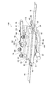
図13と同じ構成について同じ符号を付した図18に示すベルト接合装置10Cは、加圧体70が上記第2実施形態と異なる。加圧体70は、枠部72と、枠部72と前記上型53の間に配置された弾性部73と、前記弾性部73を前記上型53に押し付けるカム機構76とを有する。
図13と同じ構成について同じ符号を付した図18に示すベルト接合装置10Cは、加圧体70が上記第2実施形態と異なる。加圧体70は、枠部72と、枠部72と前記上型53の間に配置された弾性部73と、前記弾性部73を前記上型53に押し付けるカム機構76とを有する。
枠部72は、図19に示すように、断面が略C形で、板状の上端部78と、上端部78と平行に配置された下端部80と、上端部78及び下端部80の一辺同士を接続する背板部82とを有する。背板部82の両側には、上端部78と下端部80の中間に、上端部78に平行に突出した中間部81とを有する。
上端部78は、中央に矩形状の貫通穴84を有する。当該貫通穴84の幅方向両側の上端部78には雌ねじ85がそれぞれ設けられている。さらに上端部78には貫通穴84を囲むように四隅に逃がし穴88が合計4個、上端部78の四隅に設置穴86が合計4個、それぞれ形成されている。
弾性部73は、保持部90を介して、上端部78の下面に支持されている。保持部90は、上端部78と平行に配置された保持板91と、保持板91の四隅に固定された軸93とを有する。保持板91は、設置穴86に挿入された軸93に戻りばね94を装填し、軸93の先端側で戻りばね94を軸93から抜けないように固定することにより、上端部78に対し、厚さ方向に移動可能に支持されている。
弾性部73は、保持板91と平行に配置された押し板92と、保持板91と押し板92の間に配置されたコイルばね74とを有する。押し板92は、保持板91に向かって突出した軸95が四隅に設けられている。当該軸95にコイルばね74を装填し、保持板91に形成された穴(図示しない)に挿入した当該軸95の先端にナット75をねじ込むことにより、保持板91に対し厚さ方向に移動可能に支持されている。
カム機構76は、板カム96と、前記板カム96に一体に形成されたレバー98と、軸100とを有する。板カム96は、図20に示すように、円盤状であって、中心からずれた位置に厚さ方向に貫通した穴97が設けられている。板カム96は、貫通穴84の幅方向に架け渡された軸100を穴97に挿入して回転可能に支持され、貫通穴84内に配置される。軸100は、ボルト102を雌ねじ85にねじ込むことにより、上端部78に固定されている。
図21に示すように、上型53と上端部78の間に、上端部78側から、保持板91、コイルばね74、押し板92の順に配置され、保持板91に板カム96が接している。カム機構76は、軸100を中心にレバー98を傾けることにより、板カム96の中心と穴97の中心の位置がずれている分だけ、上端部78から下側に突出する板カム96の長さを変えることができる。下端部80は、ヒータ56の下面との間に隙間を開けた状態で配置されている。中間部81は、下型52の下面に接している。保持体51は、背板部82の厚さ方向にねじ込まれた調節ねじ104によって、枠部72の奥行方向に対し位置決めされる。
レバー98を一側に傾け、回転した板カム96が上端部78から下側により多く突出した場合、図18に示すように、カム機構76は、押し板92を上型53に押し付けることができる。すなわち板カム96が回転し上端部78から下側に突出すると、保持板91を下側へ押し付ける。保持板91は、戻りばね94が収縮することにより、上端部78から離れるように下側へ移動する。保持板91の移動に伴い、押し板92は上型53に接触するまで下降する。板カム96が上端部78から下側へ突出した分だけ、大きな力で第1ベルト端部16及び第2ベルト端部18を厚さ方向に加圧することができる。押し板92には、押し板92が上型53を押す力と同じ大きさの反力が働く。当該反力がコイルばね74の復元力より大きくなった場合、その分だけコイルばね74は収縮する。ベルト接合装置10Cは、コイルばね74が収縮することにより、押し板92が上型53を押し付ける力が過剰になることを防止することができる。
レバー98を他側に傾け、上端部78から下側に突出する板カム96の長さを短くした場合、図22に示すように、カム機構76は、押し板92による上型53への押し付けを解除することができる。すなわち、板カム96の回転によって上端部78から下側に突出する板カム96の長さが小さくなると、戻りばね94の復元力によって保持板91が上端部78へ向かって移動する。保持板91の移動に伴い、押し板92は上型53から離れ、上昇する。軸95の先端が逃がし穴88を通過することにより保持板91は、上端部78に接触し得る。
本実施形態の場合、レバー98を一側又は他側へ傾けて倒すことにより、上型53を通じて第1ベルト端部16及び第2ベルト端部18を厚さ方向に加圧すると共に、加圧を解除することができる。
弾性部73は、押し板92とコイルばね74を有する場合に限定されない。例えば、図23に示すベルト接合装置10Dのように、弾性部としてゴム板110を用いてもよい。ゴム板110は、保持板91の下面側、すなわち上型53側の表面に直接固定されている。本変形例の場合、レバー98を操作することにより、第1ベルト端部16及び第2ベルト端部18を厚さ方向に加圧したり、加圧を解除したりすることができる。この場合、枠部112は、上端部78の逃がし穴88を省略することができる。
4.変形例
本発明は上記実施形態に限定されるものではなく、本発明の趣旨の範囲内で適宜変更することが可能である。上記実施形態の場合、第1接合部17及び第2接合部19は、予めベルト本体15に接合されている場合について説明したが、本発明はこれに限らない。例えば、接合部は、ベルト本体と別体とし、保持体に固定された第1ベルト端部及び第2ベルト端部間に配置してもよい。ヒータは、柱状のヒータを用いてもよい。
本発明は上記実施形態に限定されるものではなく、本発明の趣旨の範囲内で適宜変更することが可能である。上記実施形態の場合、第1接合部17及び第2接合部19は、予めベルト本体15に接合されている場合について説明したが、本発明はこれに限らない。例えば、接合部は、ベルト本体と別体とし、保持体に固定された第1ベルト端部及び第2ベルト端部間に配置してもよい。ヒータは、柱状のヒータを用いてもよい。
10A、10B、10C、10D ベルト接合装置
12 保持体
14 加圧体
16 第1ベルト端部
18 第2ベルト端部
20 上型
22 下型
24 クランプ本体
26 ベルトクランプ
48 凸部
49 表面
50 閉塞突起
12 保持体
14 加圧体
16 第1ベルト端部
18 第2ベルト端部
20 上型
22 下型
24 クランプ本体
26 ベルトクランプ
48 凸部
49 表面
50 閉塞突起
Claims (8)
- 第1ベルト端部と、第2ベルト端部の両端部を突き合わせて保持する保持体と、
前記両端部を厚さ方向に加圧する加圧体と
を備えるベルト接合装置であって、
前記保持体は、
前記第1ベルト端部及び前記第2ベルト端部が上面に載置される下型と、
前記第1ベルト端部及び前記第2ベルト端部の上面に配置される上型と、
ベルトクランプと、
前記第1ベルト端部又は前記第2ベルト端部を間に挟んで前記ベルトクランプが着脱自在に固定される少なくとも1つのクランプ本体と、
前記第1ベルト端部及び前記第2ベルト端部を加熱するヒータと
を有し、
前記クランプ本体と前記下型の間にベルト引き寄せ機構を備えるベルト接合装置。 - 前記ベルト引き寄せ機構は、
前記下型の下面に設けられた凸部と、
前記クランプ本体に形成された穴と
を有し、
前記凸部は、前記クランプ本体が接続される前記下型の一側面から突出しており、
前記クランプ本体は、前記穴の、前記下型から遠い側の一部の上面を塞ぐ閉塞突起を有する
請求項1記載のベルト接合装置。 - 前記閉塞突起は、下端から上端に向かって、前記穴の半径方向の外向きに傾斜している請求項2記載のベルト接合装置。
- 前記ベルトクランプは、前記クランプ本体にねじで固定される請求項1~3のいずれか1項記載のベルト接合装置。
- 前記加圧体は、枠部と、前記枠部と前記上型の間に配置された弾性部と、前記弾性部を前記上型に押し付けるカム機構とを有する請求項1~4のいずれか1項記載のベルト接合装置。
- 前記弾性部は、コイルばねである請求項5記載のベルト接合装置。
- 前記弾性部は、ゴム板である請求項5記載のベルト接合装置。
- 前記カム機構は、前記枠部に回転可能に支持された板カムと、前記板カムに一体に形成されたレバーとを有する請求項5~7のいずれか1項記載のベルト接合装置。
Applications Claiming Priority (4)
| Application Number | Priority Date | Filing Date | Title |
|---|---|---|---|
| JP2017072998 | 2017-03-31 | ||
| JP2017-072998 | 2017-03-31 | ||
| JP2017-236021 | 2017-12-08 | ||
| JP2017236021A JP6397982B1 (ja) | 2017-03-31 | 2017-12-08 | ベルト接合装置 |
Publications (1)
| Publication Number | Publication Date |
|---|---|
| WO2018181952A1 true WO2018181952A1 (ja) | 2018-10-04 |
Family
ID=63668448
Family Applications (1)
| Application Number | Title | Priority Date | Filing Date |
|---|---|---|---|
| PCT/JP2018/013761 Ceased WO2018181952A1 (ja) | 2017-03-31 | 2018-03-30 | ベルト接合装置 |
Country Status (3)
| Country | Link |
|---|---|
| JP (1) | JP6397982B1 (ja) |
| TW (1) | TW201838795A (ja) |
| WO (1) | WO2018181952A1 (ja) |
Cited By (1)
| Publication number | Priority date | Publication date | Assignee | Title |
|---|---|---|---|---|
| CN110354511A (zh) * | 2019-07-10 | 2019-10-22 | 东莞市文博工艺品有限公司 | 一种硅胶公仔生产流水线 |
Families Citing this family (2)
| Publication number | Priority date | Publication date | Assignee | Title |
|---|---|---|---|---|
| KR102033648B1 (ko) * | 2019-06-14 | 2019-10-17 | 이지윤 | 심리스 타입 라운드벨트 제조장치 및 이를 이용한 제조방법 |
| JP7546440B2 (ja) | 2020-10-09 | 2024-09-06 | ニッタ株式会社 | ベルト引寄せ治具 |
Citations (3)
| Publication number | Priority date | Publication date | Assignee | Title |
|---|---|---|---|---|
| JPH0347864Y2 (ja) * | 1983-09-30 | 1991-10-14 | ||
| JP2566296Y2 (ja) * | 1992-07-09 | 1998-03-25 | バンドー化学株式会社 | 樹脂ベルトのエンドレス化装置 |
| JP2009226761A (ja) * | 2008-03-24 | 2009-10-08 | Nitta Ind Corp | ベルト接合治具 |
-
2017
- 2017-12-08 JP JP2017236021A patent/JP6397982B1/ja active Active
-
2018
- 2018-03-30 WO PCT/JP2018/013761 patent/WO2018181952A1/ja not_active Ceased
- 2018-03-31 TW TW107111494A patent/TW201838795A/zh unknown
Patent Citations (3)
| Publication number | Priority date | Publication date | Assignee | Title |
|---|---|---|---|---|
| JPH0347864Y2 (ja) * | 1983-09-30 | 1991-10-14 | ||
| JP2566296Y2 (ja) * | 1992-07-09 | 1998-03-25 | バンドー化学株式会社 | 樹脂ベルトのエンドレス化装置 |
| JP2009226761A (ja) * | 2008-03-24 | 2009-10-08 | Nitta Ind Corp | ベルト接合治具 |
Cited By (1)
| Publication number | Priority date | Publication date | Assignee | Title |
|---|---|---|---|---|
| CN110354511A (zh) * | 2019-07-10 | 2019-10-22 | 东莞市文博工艺品有限公司 | 一种硅胶公仔生产流水线 |
Also Published As
| Publication number | Publication date |
|---|---|
| JP6397982B1 (ja) | 2018-09-26 |
| JP2018171888A (ja) | 2018-11-08 |
| TW201838795A (zh) | 2018-11-01 |
Similar Documents
| Publication | Publication Date | Title |
|---|---|---|
| JP6397982B1 (ja) | ベルト接合装置 | |
| US8118966B2 (en) | Method for producing joined belt | |
| RU2340457C1 (ru) | Способ соединения ремня, приспособление для предварительной установки и устройство для соединения ремня | |
| TW201616585A (zh) | 安裝用頭及使用其之安裝裝置 | |
| CA3036995C (en) | Sidewall bonder and method for bonding sidewalls to thermoplastic belts | |
| US7882879B2 (en) | Apparatus for bonding rubber O-Rings and extrusions | |
| JP4861749B2 (ja) | モールド装置およびモールド品の製造方法 | |
| US9689049B2 (en) | Electric heating device | |
| CN113014045B (zh) | 用于旋转电机芯的制造方法和制造装置 | |
| US20070164494A1 (en) | Clamping device for a curing process | |
| JP4972434B2 (ja) | 平ベルトの融着用治具および融着プレス装置 | |
| CN105848856B (zh) | 层压装置 | |
| JP7293290B2 (ja) | 融着装置及び融着方法 | |
| WO2018181951A1 (ja) | ベルト接合装置 | |
| JP7534964B2 (ja) | 加圧装置 | |
| CN214726707U (zh) | 防粘层快换机构及热压机构 | |
| JP4978345B2 (ja) | ベルト固定機構及び搬送装置 | |
| KR101484643B1 (ko) | 열압착용 패드 제조장치 및 제조방법 | |
| JP2022066181A (ja) | フランジシール | |
| KR20200110173A (ko) | 유체 제어 장치 | |
| JP7816546B2 (ja) | プレスヘッド、プレス装置、半導体製造装置、および電子部品製造装置 | |
| JP2006264039A (ja) | 圧着装置および圧着方法 | |
| KR20180124917A (ko) | 온도 조절가능한 음료 홀더 | |
| JP2009226761A (ja) | ベルト接合治具 | |
| JP2009107124A (ja) | 熱可塑性無端ベルトの製造装置、及び、熱可塑性無端ベルトの製造方法 |
Legal Events
| Date | Code | Title | Description |
|---|---|---|---|
| 121 | Ep: the epo has been informed by wipo that ep was designated in this application |
Ref document number: 18777463 Country of ref document: EP Kind code of ref document: A1 |
|
| DPE1 | Request for preliminary examination filed after expiration of 19th month from priority date (pct application filed from 20040101) | ||
| NENP | Non-entry into the national phase |
Ref country code: DE |
|
| 122 | Ep: pct application non-entry in european phase |
Ref document number: 18777463 Country of ref document: EP Kind code of ref document: A1 |