WO2018181844A1 - 賦形方法及び賦形装置並びに製造方法及び製造装置 - Google Patents
賦形方法及び賦形装置並びに製造方法及び製造装置 Download PDFInfo
- Publication number
- WO2018181844A1 WO2018181844A1 PCT/JP2018/013511 JP2018013511W WO2018181844A1 WO 2018181844 A1 WO2018181844 A1 WO 2018181844A1 JP 2018013511 W JP2018013511 W JP 2018013511W WO 2018181844 A1 WO2018181844 A1 WO 2018181844A1
- Authority
- WO
- WIPO (PCT)
- Prior art keywords
- resin material
- shaping
- fiber resin
- fiber
- unit
- Prior art date
- Legal status (The legal status is an assumption and is not a legal conclusion. Google has not performed a legal analysis and makes no representation as to the accuracy of the status listed.)
- Ceased
Links
Images









Classifications
-
- B—PERFORMING OPERATIONS; TRANSPORTING
- B29—WORKING OF PLASTICS; WORKING OF SUBSTANCES IN A PLASTIC STATE IN GENERAL
- B29C—SHAPING OR JOINING OF PLASTICS; SHAPING OF MATERIAL IN A PLASTIC STATE, NOT OTHERWISE PROVIDED FOR; AFTER-TREATMENT OF THE SHAPED PRODUCTS, e.g. REPAIRING
- B29C53/00—Shaping by bending, folding, twisting, straightening or flattening; Apparatus therefor
- B29C53/02—Bending or folding
-
- B—PERFORMING OPERATIONS; TRANSPORTING
- B29—WORKING OF PLASTICS; WORKING OF SUBSTANCES IN A PLASTIC STATE IN GENERAL
- B29C—SHAPING OR JOINING OF PLASTICS; SHAPING OF MATERIAL IN A PLASTIC STATE, NOT OTHERWISE PROVIDED FOR; AFTER-TREATMENT OF THE SHAPED PRODUCTS, e.g. REPAIRING
- B29C70/00—Shaping composites, i.e. plastics material comprising reinforcements, fillers or preformed parts, e.g. inserts
- B29C70/04—Shaping composites, i.e. plastics material comprising reinforcements, fillers or preformed parts, e.g. inserts comprising reinforcements only, e.g. self-reinforcing plastics
- B29C70/28—Shaping operations therefor
- B29C70/54—Component parts, details or accessories; Auxiliary operations, e.g. feeding or storage of prepregs or SMC after impregnation or during ageing
Definitions
- the present invention comprises a shaping method and a shaping device for shaping a continuous fiber resin material comprising fibers and a resin, and a continuous fiber resin material comprising fibers and a resin.
- the present invention relates to a manufacturing method and a manufacturing apparatus for manufacturing a fiber resin molded product.
- Fiber reinforced resin compositions are lightweight and excellent in mechanical properties, and are therefore used in a wide range of fields from aerospace applications to sports applications.
- a manufacturing apparatus for manufacturing a three-dimensional shape for example, a 3D (three-dimensional) printer that stacks molten thermoplastic resins is known, and in recent years, this 3D printer technology has been applied.
- molds a FRP molded object is proposed (for example, patent document 1). In this technique, a fiber resin material in which a molten thermoplastic resin and fibers are integrated is laminated on a mold material, and a fiber resin material is further laminated on the laminated fiber resin material.
- the shaping method according to the present disclosure is a shaping method for shaping a continuous fiber resin material that is made of fibers and a resin and is supplied, and can freely move the fiber resin material that is supplied and moved Change the shape to shape.
- the shaping device according to the present disclosure is a shaping device for shaping a continuous fiber resin material that is made of fibers and a resin and is supplied, and the moving direction of the fiber resin material that is supplied and moved can be freely set. It is equipped with a change unit that makes it change.
- the manufacturing method according to the present disclosure is a method for manufacturing a fiber resin molded article formed by forming a continuous fiber resin material that includes fibers and a resin, and the fiber resin material is supplied and supplied.
- a manufacturing apparatus includes a supply unit that supplies the fiber resin material in a manufacturing apparatus that manufactures a fiber resin molded article formed by shaping a continuous fiber resin material including fibers and a resin. And a shaping unit that shapes the fiber resin material in a freely shapeable manner, and the shaping unit is the shaping device described above.
- the fiber resin material can be shaped into an arbitrary shape without the need for a mold material.
- the shaping method is a shaping method for shaping a continuous fiber resin material that is made of fibers and a resin and is fed, and the fiber resin material that is fed and moved Shape by changing the direction of movement freely.
- the change in the moving direction can be freely changed in a direction intersecting the plane with the posture of the deforming portion that deforms the fiber resin material in a plane including the fiber resin material to be supplied. It is done by doing. Thereby, the moving direction of the fiber resin material can be easily changed.
- the deformable portion is freely rotated around a virtual axis existing in the plane.
- the fiber resin material can be shaped freely in three dimensions.
- the deformable portion is freely moved in a direction intersecting the plane. Thereby, the fiber resin material can be shaped freely in three dimensions.
- the moving direction of the fiber resin material exiting from the deforming portion is changed with respect to the moving direction of the fiber resin material entering the deforming portion. Thereby, the moving direction of the fiber resin material can be easily changed.
- the shaping apparatus is a shaping apparatus for shaping a continuous fiber resin material that is made of fibers and a resin and is fed, and freely moves a direction of the fiber resin material that is fed and moved.
- a change unit to be changed is provided.
- the changing unit changes a posture of the deforming portion in a direction intersecting the plane with a deforming portion that deforms the fiber resin material in a plane including the supplied fiber resin material. Prepare freely. Thereby, the moving direction of the fiber resin material can be easily changed.
- a method of manufacturing a fiber resin molded article wherein the fiber resin material is supplied in the method of manufacturing a fiber resin molded article formed by forming a continuous fiber resin material including fibers and a resin.
- the supplied fiber resin material is shaped freely, and the shaping is performed by the above shaping method.
- An apparatus for manufacturing a fiber resin molded product according to one aspect includes a supply unit for supplying the fiber resin material in a manufacturing device for manufacturing a fiber resin molded product formed by shaping a continuous fiber resin material composed of fibers and a resin. And a shaping unit that shapes the supplied fiber resin material so as to be freely shaped, and the shaping unit is the shaping device described above.
- the resin of the fiber resin material is a plastic resin
- the supply unit supplies the fiber resin material to the shaping unit in a state of being plastically deformable.
- the shaping method and shaping apparatus and the manufacturing method and manufacturing apparatus which are aspects of the present disclosure.
- the shaping method or shaping apparatus which is one aspect is to form a continuous fiber resin material C composed of fibers A and resins B.
- the fiber resin material C is shaped freely by changing the moving direction of the fiber resin material C that is supplied and moved.
- the shaping apparatus includes a changing unit that freely changes the moving direction of the fiber resin material C that is supplied and moved.
- the manufacturing apparatus includes the shaping apparatus as a shaping unit.
- the fiber A may be a long fiber, a short fiber, or both a long fiber and a short fiber.
- the long fiber refers to a fiber of 100 [mm] or more, and includes so-called continuous fibers.
- the short fiber refers to a fiber of less than 100 [mm], and includes a so-called milled fiber.
- the form of the fiber A may be composed of a single filament, or may be composed of a fiber bundle in which a plurality of filaments are bundled. Fiber A may or may not adhere to a resin as a matrix constituting the fiber resin molded product D. When the fiber A is in the form of a bundle, it may be composed of the same type of fiber, or may be composed of a plurality of types of fibers. Examples of the fiber include carbon fiber, glass fiber, aramid fiber, boron fiber, and metal fiber.
- Resin Resin B may be a curable resin before curing or may be a plastic resin.
- Curable resin is a resin that is cured by heat, light (ultraviolet rays or infrared rays) and the like.
- the curable resin include epoxy resin, vinyl ester resin, bismaleimide resin, polyimide resin, cyanate ester resin, phenol resin, melamine resin, benzoxazone resin, unsaturated polyester resin, silicon resin, polyurethane resin, and the like.
- the mixture of these resin can also be used as resin.
- modifiers such as plastic resins, flame retardants, inorganic fillers, internal mold release agents and the like may be blended.
- plastic resin is a resin that melts with heat, light (ultraviolet rays or infrared rays), and solidifies after melting.
- the plastic resin include a polyethylene resin, a polypropylene resin, a polyolefin resin that is a copolymer or a blend thereof, an aliphatic polyamide resin such as polyamide 66, polyamide 6, polyamide 12, and the like, and a half having an aromatic component as an acid component.
- Aromatic polyamide resin aromatic polyester resin such as polyethylene terephthalate resin (PET) and polybutylene terephthalate resin (PBT), polycarbonate resin, polystyrene resin (polystyrene resin, AS resin, ABS resin, etc.), polylactic acid Aliphatic polyester resins such as polysulfone resin (PSu), polyethersulfone resin (PES), polyetherimide resin (PEI), polyetherketone resin (PEK), polyetheretherketone resin (PEEK) That. Moreover, the mixture of these resin can also be used as resin.
- PET polyethylene terephthalate resin
- PBT polybutylene terephthalate resin
- PBT polycarbonate resin
- polystyrene resin polystyrene resin
- AS resin AS resin
- ABS resin ABS resin
- polylactic acid Aliphatic polyester resins such as polysulfone resin (PSu), polyethersulfone resin (PES), polyetherimide resin (PEI), polyetherketone
- the fiber resin material C is a material containing at least the fiber A and the resin B.
- the resin B is a curable resin
- the fiber resin material C does not have a shape-retaining force that maintains its own shape.
- the resin B is a plastic resin, as long as the resin B is in a state that can be plastically deformed, the resin may be in a molten state or a softened state before the shaping.
- the fiber resin molded product D is obtained by molding (solidifying) a fiber resin material C composed of fibers A and resins B.
- the fiber resin material C refers to a state before curing with a curable resin, and refers to a state before solidified into the shape of the fiber resin molded product D with a plastic resin.
- the fiber resin molded product D becomes a fiber reinforced resin molded product.
- the fiber resin molded product D refers to the one that can maintain the shape of the fiber resin material C after shaping (if there are multiple shapings, it is the final shaping).
- the resin B is a curable resin
- the resin B constituting the fiber resin molded product D may not be completely cured, and may be completely cured later (post cure).
- the changing unit freely changes the moving direction of the fiber resin material C to be supplied, and shapes the fiber resin material C to be freely shaped.
- the changing unit includes a deformable portion that deforms the fiber resin material C in a plane including or out of the plane including the fiber resin material C (center axis thereof) so that the posture can be freely changed.
- the deforming portion may be provided so as to be rotatable around a virtual axis existing in the plane.
- the virtual axis may be provided in the vertical direction, may be provided in the horizontal direction, or may be provided in the vertical direction or a direction inclined with respect to the horizontal direction.
- the virtual axis may exist outside the deforming part, or may exist inside the deforming part.
- the deformable portion may be provided so as to be movable in a direction intersecting the plane (outside the plane). In this case, the intersecting direction includes a direction orthogonal to the plane.
- transformation part changes the movement direction of the said fiber resin material which comes out of the said deformation
- the outlet side portion of the fiber resin material in the deformable portion is in contact with the fiber resin material moving in the deformable portion, and the outlet side portion is provided so as to be movable relative to the inlet side portion of the deformable portion. It has been.
- the deforming portion may be provided with an intermediate portion that contacts the fiber resin material moving in the deforming portion so as to be movable with respect to the inlet side portion between the inlet side portion and the outlet side portion, or may be provided in a fixed manner. Good.
- the intermediate portion may be the entire region between the inlet side and the outlet side, or may be a partial region.
- abuts with a fiber resin material may be one, and may be plural.
- the deformable portion includes a pair of rollers on the outlet side portion that rotate around an axis orthogonal to the plane to feed the fiber resin material. The rotational speed of each of the pair of rollers can be adjusted.
- Manufacturing apparatus A manufacturing apparatus manufactures the fiber resin molding D formed by shaping the continuous fiber resin material C which consists of the fiber A and resin B.
- the manufacturing apparatus includes a supply unit that supplies the fiber resin material C, and a shaping unit that shapes the fiber resin material C that is supplied and moved in a formable manner, and the shaping unit is shaped as described above. Device.
- the supply unit only needs to supply the fiber resin material C.
- the fiber A and the resin B may be separately supplied to be the fiber resin material C, or may be supplied, or the fiber resin material C may be directly supplied.
- the fiber resin material C may be supplied continuously. In the case where the fiber resin material C is supplied without being stopped, the fiber resin material C is supplied intermittently (with a time interval). Including the case where the supply is stopped and supplied after a predetermined time has elapsed). That is, it is only necessary that the continuous fiber resin material C can be supplied without being cut halfway.
- the supply unit includes a moving unit that moves the supplied fiber resin material C to the downstream side.
- the moving part may be on the downstream side of the shaping unit, on the upstream side of the shaping unit, or on both sides of the downstream side and the upstream side of the shaping unit.
- the supply unit may move the fiber resin material C having a certain degree of rigidity to be extruded from the upstream side to the shaping unit, or may apply the fiber resin material (semi-molded product) C that has been hardened or solidified to some extent. It may be moved so as to be pulled from the downstream side of the shape unit.
- the supply unit supplies the fiber resin material C to the shaping unit in a state in which plastic deformation is possible.
- the supply unit does not require energy applying means for making the fiber resin material C plastically deformable, and supplies the solidified fiber resin material C.
- an energy application means is required for making the plastically deformable state possible.
- the energy applying means include a heating means for heating the fiber resin material C and a light irradiation means for irradiating the fiber resin material C with light.
- the manufacturing apparatus may include solidification promoting means for promoting the solidification of the resin on the downstream side of the shaping unit.
- the solidification promoting means for example, cooling means for cooling the fiber resin material C (for example, a means for blowing cool air, a contact means for contacting a member having a lower temperature than the fiber resin material, etc.).
- the supply unit includes energy applying means for curing the resin of the fiber resin material C.
- energy applying means for curing the resin of the fiber resin material C.
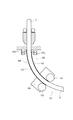
- Embodiment 1 (1) Configuration The configurations of the shaping apparatus and the manufacturing apparatus according to the first embodiment in the first embodiment will be described with reference to FIG.
- the shaping apparatus 101 has a change unit 103.
- the change unit 103 has a deforming unit 105.
- the deformation portion 105 deforms the fiber resin material C in a plane including the central axis of the fiber resin material C (the paper surface in FIG. 1 and referred to as “deformation plane”).
- the fiber resin material C is moving from the upper side to the lower side.
- transformation part 105 has a pair of board
- the main surfaces of the pair of plate members 107 here are orthogonal to the deformation plane.
- plate material 107 is contact
- the upper ends of the pair of plate materials 107 are the inlet side portions 107a of the fiber resin material C, and the lower ends of the pair of plate materials 107 are the outlet side portions 107b of the fiber resin material C.
- the deformable portion 105 includes a support body 109 at the lower end of the pair of plate members 107.
- the support 109 is provided so as to be movable (swinging) in the deformation plane (more precisely, a portion of the support located in the deformation plane is provided so as to be movable in the plane).
- the fiber resin material C can be deformed in the deformation plane by the movement of the support 109. In other words, the part located in the deformation plane in the fiber resin material C can be deformed in the plane.
- the support body 109 is supported by a plurality of wires, and moves when a predetermined wire is wound around a roller.
- the deformation unit 105 is provided so as to be rotatable around a virtual axis in the deformation plane with respect to the base 111 of the shaping apparatus 101.
- the pins 107c provided on the pair of plate members 107 are inserted into the holes 113a of the support portion 113 of the base 111 and are rotatably supported.
- the virtual axis here is the left-right direction in FIG. 1 (the direction perpendicular to the up-down direction) and coincides with the central axis of the pin 107c.
- the fiber resin material C can be freely deformed in two directions, ie, a deformation plane and a direction orthogonal to the deformation plane.
- the manufacturing apparatus 121 includes a shaping apparatus 101 as a shaping unit (reference numeral “101”) for shaping the fiber resin material C.
- the manufacturing apparatus 121 includes a supply unit 123 that supplies the fiber resin material C.
- the resin constituting the fiber resin material C here uses a thermoplastic resin, and a rod-shaped fiber resin material C having rigidity is supplied.
- the supply unit 123 includes a plurality of pairs of nip rollers 125.
- the manufacturing apparatus 121 includes a heating unit 127 that heats the fiber resin material C on the upstream side of the shaping unit 101. Heating is performed so that the fiber resin material C can be plastically deformed.
- the temperature is about 5 [° C.] to 150 [° C.] higher than the softening temperature of the resin.
- the temperature is preferably about 10 [° C.] to 100 [° C.] higher than the softening temperature of the resin, and more preferably about 10 [° C.] to 80 [° C.] higher than the softening temperature of the resin. It is.
- the manufacturing apparatus 121 includes a moving unit 131 that moves the shaped fiber resin material C downward.
- the moving unit 131 here is constituted by a pair of nip rollers 133.
- a pair of nip rollers 133 is provided on the support 109.
- the manufacturing apparatus 121 includes a pair of nip rollers 133 as a cooling unit for cooling the fiber resin material C.
- the shaping method of the fiber resin material C by the shaping apparatus 101 is demonstrated using FIG.
- the shaping apparatus 101 is supplied with a fiber resin material C in a plastically deformable state. Therefore, the fiber resin material C that passes through the deformable portion 105 is in a state that can be plastically deformed.
- the pair of plate members 107 constituting the deforming portion 105 is elastically deformed by the movement of the support body 109.
- the deforming portion 105 is deformed so as to be bent toward the right side. Thereby, the advancing direction of the fiber resin material C that contacts the pair of plate members 107 is changed to the right side, and as a result, the fiber resin material C is deformed (shaped) so as to be bent to the right side.
- the shaped fiber resin material C is sent out by the moving unit 131 provided on the support 109 and cooled. Thereby, the curved fiber resin molding D is manufactured.
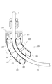
- Embodiment 2 (1) Configuration The configuration of the shaping unit, the manufacturing apparatus, and the like according to the second embodiment in the first embodiment will be described with reference to FIG.
- the shaping apparatus 201 has a change unit 203.
- the change unit 203 has a deforming unit 205.
- the deformation portion 205 deforms the fiber resin material C in a plane including the central axis of the fiber resin material C (the paper surface in FIG. 3 and referred to as “deformation plane”).
- the fiber resin material C is moving from the upper side to the lower side.
- the deforming portion 205 has a pair of belt bodies 207 disposed on both sides of the fiber resin material C that moves downward. The surfaces of the pair of belt bodies 207 are orthogonal to the deformation plane.
- the pair of belt bodies 207 are provided so as to be freely bent in the left-right direction in FIG.
- the pair of belt bodies 207 is in contact with or close to the fiber resin material C moving downward.
- the upper ends of the pair of belt bodies 207 are the inlet side portions 207a of the fiber resin material C, and the lower ends of the pair of belt bodies 207 are the outlet side portions 207b of the fiber resin material C.
- the deformation unit 205 includes a support body 211 on the lower end side of the pair of belt bodies 207.
- the support 211 is provided so as to be movable (swingable) in the deformation plane.
- the support 211 is provided with a driving roller 209 for rotating the belt 207.
- the fiber resin material C can be deformed in the deformation plane by the movement of the support 211.
- the support body 211 moves using a wire similarly to the support body 109 of Embodiment 1.
- the deformation unit 205 is provided so as to be rotatable around a virtual axis in the deformation plane with respect to the base 215 of the shaping apparatus 201.
- the pin 221 of the mounting body 219 for mounting the pair of driven rollers 217 disposed on the inner side of the upper end of each belt body 207 is inserted into the hole 225a of the support portion 225 of the base 215, and the deformable portion 205 is rotatably supported. Is done.
- the virtual axis here is the left-right direction in FIG. 3 (the direction perpendicular to the up-down direction) and coincides with the central axis of the pin 221.
- the fiber resin material C can be freely deformed in two directions, ie, a deformation plane and a direction orthogonal to the deformation plane.
- the manufacturing apparatus 231 includes a shaping apparatus 201 as a shaping unit (reference numeral “201”) for shaping the fiber resin material C. Similar to the first embodiment, the manufacturing apparatus 231 includes a supply unit 123 and a heating unit 127. The manufacturing apparatus 231 also includes a belt body 207 as a moving unit that moves the shaped fiber resin material C downward. The manufacturing apparatus 231 also includes a drive roller 209 as a cooling unit for cooling the fiber resin material C.
- the shaping apparatus 201 is supplied with the fiber resin material C in a plastically deformable state. Therefore, the fiber resin material C that passes through the deformable portion 205 is in a state that can be plastically deformed.
- the pair of belt bodies 207 constituting the deforming portion 205 is deformed so as to be bent rightward in FIG. 4 by the movement of the support body 211. Thereby, the advancing direction of the fiber resin material C contacting the pair of belt bodies 207 is changed to the right side, and as a result, the fiber resin material C is deformed (shaped) so as to be bent to the right side.
- the shaped fiber resin material C is sent out by the pair of belt bodies 207 and cooled. Thereby, the curved fiber resin molding D is manufactured.
- the shaping apparatus 301 has a change unit 303.
- the change unit 303 has a deformation unit 305.
- the deformation portion 305 deforms the fiber resin material C in a plane including the central axis of the fiber resin material C (the paper surface in FIG. 5 and referred to as “deformation plane”).
- the fiber resin material C is moving from the upper side to the lower side.
- the deformation part 305 has three rollers 307, 309, and 311 arranged on both sides of the fiber resin material C that moves downward.
- the both sides of the fiber resin material C are the directions orthogonal to the fiber resin material C moving downward in the deformation plane and are both sides with respect to the fiber resin material C, and are both the left and right sides in FIG.
- the rollers 307 and 309 are arranged on one side of the fiber resin material C and at intervals along the moving direction of the fiber resin material C.
- the rollers 307, 309, 311 abut against the fiber resin material C and rotate in a direction to move (send) the fiber resin material C downward.
- a roller 307 is disposed on the upstream side.
- the roller 311 is disposed between the rollers 307 and 309 on the other side of the fiber resin material C.
- the roller 311 is provided so as to be movable with respect to the fiber resin material C in a perspective direction (a direction orthogonal to the fiber resin material C). When the roller 311 moves to the fiber resin material C side, the fiber resin material C is deformed in the deformation plane.
- the roller 307 corresponds to the inlet side portion of the fiber resin material C in the deformation portion 305
- the roller 309 corresponds to the outlet side portion of the fiber resin material C in the deformation portion 305.
- the deforming unit 305 is around the virtual axis in the deformation plane with respect to the base 315 of the shaping apparatus 301 as in the first and second embodiments (hereinafter referred to as “first embodiment”). It is provided to be freely rotatable.
- the manufacturing apparatus 331 includes a shaping apparatus 301 as a shaping unit (reference numeral “301”) for shaping the fiber resin material C.
- the manufacturing apparatus 331 includes a supply unit 123 and a heating unit 127 as in the first embodiment.
- the manufacturing apparatus 331 includes rollers 309 and 311 as a moving unit that moves the shaped fiber resin material C downward.
- the manufacturing apparatus 331 includes a roller 309 as a cooling unit for cooling the fiber resin material C.
- the shaping apparatus 401 has a change unit 403.
- the change unit 403 has a deformation unit 405.
- the deformation portion 405 deforms the fiber resin material C in a plane including the central axis of the fiber resin material C (the paper surface in FIG. 6 and referred to as “deformation plane”).
- the fiber resin material C is moving from the upper side to the lower side.
- the deformable portion 405 includes a plurality (three in this example) of guide bodies 407, 409, and 411 having through holes through which the fiber resin material C moving downward is passed.
- the plurality of guide bodies 407, 409, 411 are arranged along the fiber resin material C at intervals or adjacent to each other.
- the guide bodies 407, 409, and 411 are provided so as to be movable in a direction (the left-right direction in FIG. 6) orthogonal to the fiber resin material C when not shaped.
- the three guide bodies 407, 409, and 411 can be individually moved, but at least the guide bodies 409 and 411 are moved so that the fiber resin material C is deformed in the deformation plane.
- the guide body 407 corresponds to the inlet side portion of the fiber resin material C in the deformable portion 405, and the guide body 411 corresponds to the outlet side portion of the fiber resin material C in the deformable portion 405.
- the guide body 409 corresponds to an intermediate portion that abuts against the fiber resin material C that moves within the deformable portion 405.
- the guide body 409 is movable in a direction orthogonal to the fiber resin material C, but may be fixed as long as the guide body 411 is movable.
- the deforming portion 405 is provided so as to be rotatable around a virtual axis in the deformation plane with respect to the base 415 of the shaping apparatus 401 as in the first embodiment.
- the manufacturing apparatus 431 includes a shaping device 401 as a shaping unit (reference numeral “401”) for shaping the fiber resin material C.
- the manufacturing apparatus 431 includes a supply unit 123 and a heating unit 127 as in the first embodiment.
- the manufacturing apparatus 431 includes a pair of rollers 435 as a moving unit 433 that moves the shaped fiber resin material C downward.
- the manufacturing apparatus 431 includes a pair of rollers 435 as a cooling unit for cooling the fiber resin material C.
- the shaping apparatus 501 has a change unit 503.
- the change unit 503 has a deformed portion (the reference numeral “503” is used).
- the deformation portion 503 deforms the fiber resin material C in a plane including the central axis of the fiber resin material C (the paper surface in FIG. 7 and referred to as “deformation plane”).
- the fiber resin material C is moving from the upper side to the lower side.
- the deformation part 503 has a pair of drive rollers 507 and 509 arranged on both sides of the fiber resin material C that moves downward.
- the both sides of the fiber resin material C here are both sides of the fiber resin material C in the direction orthogonal to the fiber resin material C in the deformation plane. In FIG. 7, it is the left-right direction.
- the pair of rollers 507 and 509 abut against the fiber resin material C moving downward, and rotate so that the fiber resin material C advances downward. Thereby, the fiber resin material C is sent out downward.
- the pair of rollers 507 and 509 have a rotation axis in a direction orthogonal to the deformation plane.
- the rotational speeds of the pair of rollers 507 and 509 are provided so as to be independently adjustable. By adjusting the rotational speeds of the rollers 507 and 509 to be different, the fiber resin material C is deformed in the deformation plane due to the speed difference.
- the upstream side of the pair of rollers 507 and 509 is the inlet side portion of the fiber resin material C, and the downstream side of the pair of rollers 507 and 509 is the outlet side portion of the fiber resin material C.
- the deforming portion 503 is provided on the frame (not shown) of the shaping apparatus 501 so as to be rotatable around a virtual axis in the deformation plane, as in the first embodiment.
- the manufacturing apparatus 521 includes a shaping apparatus 501 as a shaping unit (reference numeral “501”) for shaping the fiber resin material C.
- the manufacturing apparatus 521 includes a supply unit 123 that supplies the fiber resin material C.
- the supply unit 123 is the same as that of the first embodiment and the description thereof is omitted.
- a thermoplastic resin is used as the resin constituting the fiber resin material C here.
- the manufacturing apparatus 521 includes a heating unit 127 that heats the fiber resin material C on the upstream side of the shaping unit 501. Note that the heating unit 127 is the same as that in the first embodiment, and the description thereof is omitted.
- the manufacturing apparatus 521 includes a moving unit that moves the shaped fiber resin material C downward.
- the moving unit is constituted by a pair of rollers 507 and 509, and the pair of rollers 507 and 509 is constituted by using both the deforming portion 503 and the moving unit.
- the manufacturing apparatus 521 includes a cooling unit (not shown) for cooling the fiber resin material C on the downstream side of the pair of rollers 507 and 509.
- a pair of rollers 507 and 509 can be used as the cooling unit.
- the forming method of the fiber resin material C by the shaping apparatus 501 is demonstrated using FIG.
- the shaping apparatus 501 is supplied with a fiber resin material C in a state in which plastic deformation is possible. Therefore, the fiber resin material C that passes through the deformable portion 503 is in a state that can be plastically deformed.
- the rotational speed of the roller 509 constituting the deformable portion 503 is larger than the rotational speed of the roller 507, and the fiber resin material C is changed to the left as shown in FIG. In particular, the fiber resin material C is deformed so as to bend to the left side.
- the shaped fiber resin material C is sent out by a moving unit including rollers 507 and 509.
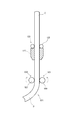
- the shaping apparatus 601 has a change unit 603.
- the change unit 603 includes a deformation unit 605.
- the deformation portion 605 deforms the fiber resin material C in a plane including the central axis of the fiber resin material C (the paper surface in FIG. 9 and referred to as “deformation plane”).
- the fiber resin material C is moving from the upper side to the lower side.
- the deformable portion 605 has a cylindrical material 607 through which the fiber resin material C moving downward is passed.
- the tubular member 607 is configured to be bendable (has flexibility).
- the upper end in the cylindrical material 607 is the inlet side portion 607a of the fiber resin material C
- the lower end in the cylindrical material 607 is the outlet side portion 607b of the fiber resin material C
- the entire area of the lower end and the upper end in the cylindrical material 607 is This is an intermediate portion 607c.
- the deformable portion 605 has a support body 609 that supports the lower end of the cylindrical member 607.
- the support 609 is movably provided in a virtual plane orthogonal to the fiber resin material C when not shaped.
- the support 609 is supported so as to be movable in the left-right direction and the direction orthogonal to the paper surface in FIG.
- the support 609 has a square shape, and each side is connected to the wires 611a to 611d.
- the four wires 611a to 611d are provided so as to be freely long and short, and the support 609 is freely moved by adjusting the length of the wires 611a to 611d.
- the upper end of the tubular member 607 is fixed to the frame 613.
- the lengths of the wires 611a to 611d are adjusted by, for example, winding or feeding the wires 611a to 611d around a roller or the like.
- the manufacturing apparatus 621 includes a shaping apparatus 601 as a shaping unit (reference numeral “601”) for shaping the fiber resin material C.
- the manufacturing apparatus 621 includes a supply unit 123 that supplies the fiber resin material C.
- the supply unit 123 is the same as that of the first embodiment and the description thereof is omitted.
- a thermoplastic resin is used as the resin constituting the fiber resin material C here.
- the manufacturing apparatus 621 includes a heating unit 127 that heats the fiber resin material C on the upstream side of the shaping unit 601 and a moving unit 131 that moves the fiber resin material C after shaping downward. Note that the heating unit 127 and the moving unit 131 are the same as those in the first embodiment and the like, and the description thereof is omitted.
- the manufacturing apparatus 621 includes a pair of nip rollers 133 as a cooling unit for cooling the fiber resin material C.
- the deformable portions 105, 205, 305, 405, and 503 of the first to third embodiments are provided so that the posture can be changed in the direction intersecting the deformation plane, but the deformable portion has a constant posture. It may be fixed in a state.
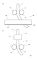
- the shaping apparatus 701 with the deformed portion fixed will be described with reference to FIG.
- the shaping apparatus 701 includes a changing unit 703 that freely changes the moving direction of the moving fiber resin material C.
- the change unit 703 includes a first deformation unit 705 and a second deformation unit 707.
- the first deformation portion 705 is located on the upstream side of the second deformation portion 707.
- the deforming portion includes a first deforming portion 705 and a second deforming portion 707.
- the first deformation portion 705 deforms the fiber resin material C in a first plane (referred to as “first deformation plane”) including the central axis of the fiber resin material C.
- the first deformation plane is a paper surface in (a) of FIG. 11 and a surface orthogonal to the paper surface in (b) of FIG.
- the first deforming portion 705 includes a pair of first rollers 711 and 713.
- the pair of first rollers 711 and 713 are provided so that the rotation speed can be individually adjusted.
- the rotation axes of the pair of first rollers 711 and 713 are orthogonal to the first deformation plane.
- the second deformation portion 707 deforms the fiber resin material C in a second plane (referred to as “second deformation plane”) that includes the central axis of the fiber resin material C and is orthogonal to the first deformation plane.
- the second deformation plane is a plane orthogonal to the paper surface in FIG. 11A and the paper surface in FIG.
- the first deformation plane and the second deformation plane are orthogonal to each other.
- the second deforming portion 707 includes a pair of second rollers 715 and 717.
- the pair of second rollers 715 and 717 are provided so that the rotation speed can be individually adjusted.
- the rotation axes of the pair of second rollers 715 and 717 are orthogonal to the second deformation plane.
- the second rollers 715 and 717 have a long overall length so as to correspond to the fiber resin material C deformed by the first deforming portion 715.
- the upper end of the first deformable portion 705 is the inlet side portion of the fiber resin material C
- the lower end of the second deformable portion 707 is the fiber resin material C. It is the exit side part.
- the shaping unit of the embodiment is shaping the fiber resin material C that moves downward from above.
- the moving direction of the fiber resin material C is not limited.
- the shaping unit may shape the fiber resin material that moves in the horizontal direction, or may shape the fiber resin material that moves in a direction inclined with respect to the horizontal direction.
- the support body 109 of the embodiment is movably provided by a wire, it may be movable by other means.
- Other means include an air cylinder and a gear.
- the change in the moving direction of the fiber resin material that is supplied and moves intersects the plane of the deformed portion that deforms the fiber resin material in the plane that includes the supplied fiber resin material.
- the orientation of the deformable portion may be freely changed in a first direction different from the direction intersecting the plane.
- the change of the moving direction of the fiber resin material that is supplied and moved is that the deformable portion is freely rotated around the virtual axis that exists in the plane including the supplied fiber resin material. It is good also as an axis
- the change in the moving direction of the fiber resin material that is supplied and moved is that the deforming portion is freely moved in a direction that intersects the plane that includes the supplied fiber resin material, but the deforming portion is moved in the first direction. You may move freely in the 3rd direction which intersects.
- the changing unit can freely change the posture of the deforming portion in a direction intersecting the plane, the deforming portion deforming the fiber resin material in a plane including the supplied fiber resin material.
- the deformable portion is rotatably provided around a virtual axis existing in a plane including the fiber resin material to be supplied, and the virtual axis is an axis extending in the second direction intersecting the first direction. Also good.
- the deforming portion is provided so as to be movable in a direction intersecting with the plane containing the fiber resin material to be supplied. However, the deforming portion is provided freely movable in a third direction intersecting with the first direction. May be.
- the shaping apparatus 401 includes guide bodies 407, 409, and 411, and the guide bodies 407, 409, and 411 are configured to move in a plane.
- each guide body may be movably provided in a virtual plane orthogonal to the fiber resin material C when not shaped, such as the support body 609 in the third embodiment.
- the shaping apparatus 401 includes guide bodies 407, 409, and 411, and the guide bodies 407, 409, and 411 are configured to move in a plane.
- the changing unit 803 of the shaping device 801 is a guide that is rotatably supported around two directions intersecting the moving direction of the fiber resin material C before entering the changing unit 803.
- a body 807 may be provided.
- the guide body 807 has a plate shape having a through hole 807a for the fiber resin material C.
- the through hole 807a may have a large opening at the entrance / exit part of the hole and a small opening at the center part in the extending direction of the hole.
- the guide body 807 is rotatably supported by a first rotating shaft 831 orthogonal to the moving direction of the fiber resin material C before entering the changing unit 803 (the vertical direction in FIG. 12).
- the first rotating shaft 831 extends from two opposing end surfaces of the guide body 807 and is rotatably supported by the first support plate 833.
- the first support plate 833 is provided on the first base 835.
- the first rotating shaft 831 is rotationally driven by driving means (not shown) (the rotational directions are two directions of normal rotation and reverse rotation).
- the first base 835 is rotatably supported by the second rotation shaft 851.
- the second rotation shaft 851 extends from two opposing end surfaces of the first base 835 and is rotatably supported by a second support plate 853.
- the second support plate 853 is provided on the second base 855.
- the second base 855 is fixed to a molding device or the like.
- the second rotating shaft 851 is rotationally driven by driving means (not shown) (the rotational direction is two directions).
- the first base 835 and the second base 855 have through holes 835a and 855a larger than the fiber resin material C so that the fiber resin material C can change the moving direction.
- the shaping apparatus 401 includes guide bodies 407, 409, and 411, and the guide bodies 407, 409, and 411 are configured to move in a plane.
- a guide body 907 that is rotatably supported around the rotation axis may be provided.
- the guide body 907 has a through hole 907a for the fiber resin material C.
- the through hole 907a may have a large opening at the entrance / exit of the hole and a small opening at the center in the extending direction of the hole.
- the guide body 907 is rotatably supported by a first rotating shaft 931 orthogonal to the moving direction of the fiber resin material C before entering the change unit 903 (the vertical direction in FIG. 13).
- the guide body 907 has a plate shape (for example, a rectangular plate shape), and has a first rotation shaft 931 at one end in a direction orthogonal to the first rotation shaft 931 (for example, a longitudinal direction when the guide body has a rectangular shape).
- a moving shaft 932 that moves in a direction orthogonal to the guide body 907 (the main surface thereof) is attached at multiple ends.
- the guide body 907 rotates around the first rotation shaft 931 so that the guide body 907 can freely tilt.
- the first rotating shaft 931 is inserted through the through hole 907b of the guide body 907 and fixedly supported by the first support plates 933 at both ends in the longitudinal direction.
- the first support plate 933 is provided on the first base 935.
- the first base 935 has a disk shape and is rotatably supported.
- the first base 935 is rotatable by a driving roller 951.
- the guide body 907 is rotatable about the vertical direction as the rotation axis.
- the 1st base 935 has the through-hole 935a larger than the fiber resin material C so that the fiber resin material C can change a moving direction.
- the shaping apparatus 401 includes guide bodies 407, 409, and 411, and the guide bodies 407, 409, and 411 are configured to move in a plane.
- the guide body 1007 has a through hole 1007a for the fiber resin material C. In the through hole 1007a, the opening at the entrance / exit part of the hole is large, and the opening at the center part in the extending direction of the hole is small.
- the guide body 1007 has a base shape having a through hole 1007a.
- the ball band 1007b of the guide body 1007 is rotatably supported by a support member (not shown).
- the first rotating roller 1031 extending parallel to the moving direction of the fiber resin material C, and the second rotating roller 1051 having an axis on a virtual plane orthogonal to the moving direction of the fiber resin material C are in contact with the spherical band 1007b of the guide body 1007.
- the first rotating roller 1031 includes a first shaft 1033 and a first roller body 1035 that is rotatably supported around the first shaft 1033 (is a free roller), and the first shaft 1033 is a shaft. Move in the stretching direction.
- the posture of the guide body 1007 can be changed with the direction orthogonal to the first axis 1033 as a rotation axis.
- the second rotating roller 1051 includes a second shaft 1053 and a second roller body 1055 that is rotatably supported around the second shaft 1053 (is a free roller), and the second shaft 1053 is a shaft. Move in the stretching direction.
- the guide body 1007 can rotate with the direction orthogonal to the virtual plane including the axis of the second axis 1053 (the vertical direction in FIG. 14) as the rotation axis.
- the rotation of the guide body 1007 is prevented when the shafts of the first rotating roller 1031 and the second rotating roller 1051 move in the extending direction. Absent. With the above configuration, the posture of the guide body 1007 can be freely changed.
- the manufacturing apparatuses 121, 231, 331, and 431 in the first embodiment, the manufacturing apparatus 521 in the second embodiment, and the manufacturing apparatus 621 in the third embodiment include the same heating unit 127.
- the heating unit is not particularly limited as long as the fiber resin material C can be heated in a plastically deformable state, and the heating method and structure are not particularly limited.
- the heating method may use an electric heater, hot air, microwave, plasma, or the like, or may be a contact type or a non-contact type.
- an electric current may be passed through the fiber A (fiber resin material C), and the fiber resin material C may be heated by Joule heat.
- Examples of conductive fibers include organic fibers having conductivity such as carbon fibers, inorganic fibers such as metal fibers such as stainless steel, organic fibers whose surface is subjected to conductive treatment (coating or coating), and conductive fillers. There are mixed organic fibers.
- a modification in which the manufacturing apparatus includes a heating unit that heats the fiber resin material C using Joule heat will be described below with reference to FIG. When Joule heat is used, the unit can be reduced in size and power can be saved.
- the manufacturing apparatus 1101 heats the fiber resin material C composed of the fibers A and the resin B, and shapes the fiber resin material C into an arbitrary shape.
- carbon fiber which is an example of conductive fiber
- a thermoplastic resin is used as the resin B.
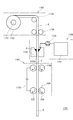
- the manufacturing apparatus 1101 includes a fiber supply unit 1103, a resin supply unit 1105, a heating unit 1107, and a shaping unit 1109. Again, in the traveling direction of the fiber A, the side on which the fiber A proceeds is the downstream side.
- the manufacturing apparatus 1101 includes a fiber supply unit 1103, a resin supply unit 1105, a heating unit 1107, and a shaping unit 1109 in this order from the upstream side.
- the manufacturing apparatus 1101 has at least one traveling roller for traveling the fiber A or the fiber resin material C.
- the manufacturing apparatus 1101 as an example includes at least a supply roller (nip roller) 1108 between the resin supply unit 1105 and the shaping unit 1109.
- the fiber A here uses a roving 1133 wound around a bobbin 1131.
- the fiber supply unit 1103 supplies the fiber A drawn from the roving 1133 while being guided by the roller 1135 and the nip roller 1136. Note that the nip roller 1136 also has a function of drawing the fiber A from the roving 1133. Further, the fiber supply unit 1103 may supply the fiber A to the shaping unit 1109, or supply the fiber A to the resin supply unit 1105 and the supply roller 1108 supplies the fiber resin material C to the shaping unit 1109. You may do that.
- the resin supply unit 1105 supplies the resin B before the fiber A reaches the shaping unit 1109.
- molten resin B is supplied to fiber A.
- the resin supply unit 1105 includes a resin storage tank 1151 that stores the resin B, a resin tank 1153 through which the fiber A passes, and a pump 1155 that sends the stored resin B to the resin tank 1153.
- the resin storage tank 1151 is provided with a heater (not shown). As a result, the resin B in the resin storage tank 1151 is melted or maintained in a molten state.
- the resin tank 1153 is provided with a through hole 1153a, and one or a plurality of fibers A pass through the through hole 1153a.
- the through-holes 1153a correspond to the thickness of a predetermined number of fibers A, and a predetermined amount of resin B is applied (supplied) to the fibers A when the fibers A pass through the through-holes 1153a of the resin tank 1153.
- the resin resin C adheres to the fiber resin material C.
- the fiber resin material C of desired cross-sectional shape is obtained by selecting the shape of the through-hole 1153a suitably. For example, a plate-like fiber resin material C is obtained when the through-hole 1153a is flattened, and a round bar-like fiber resin material C is obtained when the through-hole 1153a is circular.
- Heating unit 1107 applies voltage to the supply roller 1108 for supplying the fiber resin material C to the shaping unit 1109 and the drive rollers 507 and 509 of the shaping unit 1109. Consists of means 1173. By applying the voltage, a current flows through the fiber A moving between the supply roller 1108 and the drive rollers 507 and 509, and the fiber resin material C is heated by Joule heat.
- the shading unit 1109 is the same as the shaving device (shaping unit) 501 in the second embodiment, and has a pair of drive rollers 507 and 509.
- the pair of drive rollers 507 and 509 have a rotation axis in a direction orthogonal to the moving direction of the fiber resin material C (fiber A) before entering the drive rollers 507 and 509.
- the drive rollers 507 and 509 are provided such that their rotational speeds can be adjusted independently.
- the fiber supply unit 1103 uses one roving 1133.
- the fiber supply unit 1203 may be supplied from two rovings 1133, or may be supplied from three or more rovings 1133.
- the fibers are pulled out from the two rovings 1133 to be one before reaching the resin supply device 1105.
- a plurality of fiber resin materials C are formed from the plurality of rovings 1133. You may make one after obtaining.
- the heating unit 1107 is one-stage heating using a set of supply rollers 1108 and the driving rollers 507 and 509 of the shaping unit 1109 along the traveling direction of the fiber resin material C. It may be heated in multiple stages along.
- the heating unit 1107 uses the driving rollers 507 and 509 of the shaping unit 1109, but may not be used.
- the heating unit 1107 uses a nip roller as the supply roller 1108, a guide roller that contacts the fiber resin material C may be used, or a metal guide or the like that guides the fiber resin material C to the shaping unit. Instead of the supply roller 1108, it may be used.
- the fiber resin molded product D sent from the shaping unit 1109 is solidified by natural cooling to maintain the shaping shape, but if natural cooling is not sufficient, the downstream side of the shaping unit A cooling unit may be provided.
- the cooling unit include a cold air unit that blows cold air.
- the shaping unit is fixed.
- the moving body may be configured to be movable in a first axis direction in which the first axis extends or in a plurality of axis directions in which each of the plurality of axes extends, or to be rotatable around the first axis or the plurality of axes.
- the molded product can be manufactured in a fixed state. Moreover, the freedom degree of the shape of a molded article increases.
- the manufacturing apparatuses 121, 231, 331, and 431 in the first embodiment, the manufacturing apparatus 521 in the second embodiment, the manufacturing apparatus 621 in the third embodiment, and the like include one shaping unit.
- two or more shaping units may be provided.
- Each of the two or more shaping units may be provided in a fixed manner, or may be provided in a movable body that is movable as described above.
- a plurality of shaping units may be provided on the fixed body or the moving body, and the molding intermediate product (intermediate) discharged from the shaping unit may be rotatably supported or movably supported.
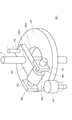
- Shaping device (Shaping unit) 105 Deformation part moving part 121 Manufacturing apparatus 123 Supply unit 127 Heating unit 131 Moving unit
Landscapes
- Engineering & Computer Science (AREA)
- Mechanical Engineering (AREA)
- Chemical & Material Sciences (AREA)
- Composite Materials (AREA)
- Moulding By Coating Moulds (AREA)
- Shaping Of Tube Ends By Bending Or Straightening (AREA)
Abstract
賦形方法は、繊維と樹脂とからなり且つ供給される連続状の繊維樹脂材料(C)を賦形する賦形方法であって、供給されて移動する繊維樹脂材料(C)の移動方向を自在に変更させて賦形する。賦形装置(101)は、繊維と樹脂とからなり且つ供給される連続状の繊維樹脂材料(C)を賦形する装置であって、供給されて移動する前記繊維樹脂材料(C)の移動方向を自在に変更させる変更ユニット(101)を備える。
Description
本発明は、繊維と樹脂とからなり且つ供給される連続状の繊維樹脂材料を賦形する賦形方法及び賦形装置並びに繊維と樹脂とからなる連続状の繊維樹脂材料を賦形してなる繊維樹脂成形物を製造する製造方法及び製造装置に関する。
繊維強化樹脂組成物(FRP成形品)は、軽量で機械特性に優れるため、航空宇宙用途からスポーツ用途等に至るまで幅広い分野において利用されている。
一方、立体的な形状(三次元形状)を有する造形物を製造する製造装置として、例えば溶融した熱可塑性樹脂を積み重ねる3D(三次元)プリンタが知られており、近年、この3Dプリンタ技術を応用して、FRP成形物を成形する技術が提案されている(例えば、特許文献1)。
この技術は、溶融した熱可塑性樹脂と繊維とが一体化された繊維樹脂材料を型材に積層し、積層した繊維樹脂材料上にさらに繊維樹脂材料を積層するものである。
一方、立体的な形状(三次元形状)を有する造形物を製造する製造装置として、例えば溶融した熱可塑性樹脂を積み重ねる3D(三次元)プリンタが知られており、近年、この3Dプリンタ技術を応用して、FRP成形物を成形する技術が提案されている(例えば、特許文献1)。
この技術は、溶融した熱可塑性樹脂と繊維とが一体化された繊維樹脂材料を型材に積層し、積層した繊維樹脂材料上にさらに繊維樹脂材料を積層するものである。
従来の技術は、型材又はすでに型材に積層された繊維樹脂材料等(以下、単に「型材等」とする。)の上に溶融状態の繊維樹脂材料を積層するため、必ず型材等が必要となる。
本開示は、上記のような問題点に着目し、型材等を必要とせずに繊維樹脂材料を任意の形状に賦形できる賦形方法等を提供することを目的とする。
本開示は、上記のような問題点に着目し、型材等を必要とせずに繊維樹脂材料を任意の形状に賦形できる賦形方法等を提供することを目的とする。
本開示に係る賦形方法は、繊維と樹脂とからなり且つ供給される連続状の繊維樹脂材料を賦形する賦形方法であって、供給されて移動する前記繊維樹脂材料の移動方向を自在に変更させて賦形する。
本開示に係る賦形装置は、繊維と樹脂とからなり且つ供給される連続状の繊維樹脂材料を賦形する賦形装置であって、供給されて移動する前記繊維樹脂材料の移動方向を自在に変更させる変更ユニットを備える。
本開示に係る製造方法は、繊維と樹脂とからなり且つ供給される連続状の繊維樹脂材料を賦形してなる繊維樹脂成形物の製造方法において、前記繊維樹脂材料を供給し、供給された前記繊維樹脂材料を形状自在に賦形し、前記賦形は請求項1~5の何れか1項に記載の賦形方法により行う。
本開示に係る製造装置は、繊維と樹脂とからなる連続状の繊維樹脂材料を賦形してなる繊維樹脂成形物を製造する製造装置において、前記繊維樹脂材料を供給する供給ユニットと、供給された前記繊維樹脂材料を形状自在に賦形する賦形ユニットとを備え、前記賦形ユニットは、上記の賦形装置である。
本開示に係る賦形装置は、繊維と樹脂とからなり且つ供給される連続状の繊維樹脂材料を賦形する賦形装置であって、供給されて移動する前記繊維樹脂材料の移動方向を自在に変更させる変更ユニットを備える。
本開示に係る製造方法は、繊維と樹脂とからなり且つ供給される連続状の繊維樹脂材料を賦形してなる繊維樹脂成形物の製造方法において、前記繊維樹脂材料を供給し、供給された前記繊維樹脂材料を形状自在に賦形し、前記賦形は請求項1~5の何れか1項に記載の賦形方法により行う。
本開示に係る製造装置は、繊維と樹脂とからなる連続状の繊維樹脂材料を賦形してなる繊維樹脂成形物を製造する製造装置において、前記繊維樹脂材料を供給する供給ユニットと、供給された前記繊維樹脂材料を形状自在に賦形する賦形ユニットとを備え、前記賦形ユニットは、上記の賦形装置である。
上記の構成において、移動する繊維樹脂材料の移動方向を自在に変更させるため、型材を必要とせずに任意形状に繊維樹脂材料を賦形できる。
<本開示の概要>
1.本開示の態様について
一態様である賦形方法は、繊維と樹脂とからなり且つ供給される連続状の繊維樹脂材料を賦形する賦形方法であって、供給されて移動する前記繊維樹脂材料の移動方向を自在に変更させて賦形する。
別態様である賦形方法において、前記移動方向の変更は、供給される前記繊維樹脂材料を含む平面内において前記繊維樹脂材料を変形させる変形部の姿勢を前記平面と交差する方向に自在に変更することで行われる。これにより容易に繊維樹脂材料の移動方向を変更できる。
別態様の賦形方法において、前記変形部を前記平面内に存在する仮想軸の周りに自在に回転させる。これにより繊維樹脂材料を三次元的に自在に賦形できる。
別態様の賦形方法において、前記変形部を前記平面と交差する方向に自在に移動させる。これにより繊維樹脂材料を三次元的に自在に賦形できる。
別態様の賦形方法において、前記平面内において、前記変形部から出る前記繊維樹脂材料の移動方向を、当該変形部に入る前記繊維樹脂材料の移動方向に対して、変更させる。これにより容易に繊維樹脂材料の移動方向を変更できる。
1.本開示の態様について
一態様である賦形方法は、繊維と樹脂とからなり且つ供給される連続状の繊維樹脂材料を賦形する賦形方法であって、供給されて移動する前記繊維樹脂材料の移動方向を自在に変更させて賦形する。
別態様である賦形方法において、前記移動方向の変更は、供給される前記繊維樹脂材料を含む平面内において前記繊維樹脂材料を変形させる変形部の姿勢を前記平面と交差する方向に自在に変更することで行われる。これにより容易に繊維樹脂材料の移動方向を変更できる。
別態様の賦形方法において、前記変形部を前記平面内に存在する仮想軸の周りに自在に回転させる。これにより繊維樹脂材料を三次元的に自在に賦形できる。
別態様の賦形方法において、前記変形部を前記平面と交差する方向に自在に移動させる。これにより繊維樹脂材料を三次元的に自在に賦形できる。
別態様の賦形方法において、前記平面内において、前記変形部から出る前記繊維樹脂材料の移動方向を、当該変形部に入る前記繊維樹脂材料の移動方向に対して、変更させる。これにより容易に繊維樹脂材料の移動方向を変更できる。
一態様の賦形装置は、繊維と樹脂とからなり且つ供給される連続状の繊維樹脂材料を賦形する賦形装置であって、供給されて移動する前記繊維樹脂材料の移動方向を自在に変更させる変更ユニットを備える。
別態様の賦形装置において、前記変更ユニットは、供給される前記繊維樹脂材料を含む平面内において前記繊維樹脂材料を変形させる変形部を、前記平面と交差する方向に前記変形部の姿勢を変更自在に備える。これにより容易に繊維樹脂材料の移動方向を変更できる。
別態様の賦形装置において、前記変更ユニットは、供給される前記繊維樹脂材料を含む平面内において前記繊維樹脂材料を変形させる変形部を、前記平面と交差する方向に前記変形部の姿勢を変更自在に備える。これにより容易に繊維樹脂材料の移動方向を変更できる。
一態様の繊維樹脂成形物の製造方法は、繊維と樹脂とからなり且つ供給される連続状の繊維樹脂材料を賦形してなる繊維樹脂成形物の製造方法において、前記繊維樹脂材料を供給し、供給された前記繊維樹脂材料を形状自在に賦形し、前記賦形は上記の賦形方法により行う。
一態様の繊維樹脂成形物の製造装置は、繊維と樹脂とからなる連続状の繊維樹脂材料を賦形してなる繊維樹脂成形物を製造する製造装置において、前記繊維樹脂材料を供給する供給ユニットと、供給された前記繊維樹脂材料を形状自在に賦形する賦形ユニットとを備え、前記賦形ユニットは、上記の賦形装置である。
別態様の繊維樹脂成形物の製造装置は、前記繊維樹脂材料の樹脂は可塑性樹脂であり、前記供給ユニットは、前記繊維樹脂材料を塑性変形可能な状態で前記賦形ユニットに供給する。これにより繊維樹脂材料を容易に賦形できる。
一態様の繊維樹脂成形物の製造装置は、繊維と樹脂とからなる連続状の繊維樹脂材料を賦形してなる繊維樹脂成形物を製造する製造装置において、前記繊維樹脂材料を供給する供給ユニットと、供給された前記繊維樹脂材料を形状自在に賦形する賦形ユニットとを備え、前記賦形ユニットは、上記の賦形装置である。
別態様の繊維樹脂成形物の製造装置は、前記繊維樹脂材料の樹脂は可塑性樹脂であり、前記供給ユニットは、前記繊維樹脂材料を塑性変形可能な状態で前記賦形ユニットに供給する。これにより繊維樹脂材料を容易に賦形できる。
2.本開示の態様である賦形方法及び賦形装置並びに製造方法及び製造装置
一つの態様である賦形方法又は賦形装置は、繊維Aと樹脂Bとからなる連続状の繊維樹脂材料Cを賦形する方法又は装置である。
賦形方法は供給されて移動する繊維樹脂材料Cの移動方向を自在に変更させることで、繊維樹脂材料Cを形状自在に賦形する。賦形装置は供給されて移動する繊維樹脂材料Cの移動方向を自在に変更させる変更ユニットを備える。製造方法は上記の賦形方法で賦形して成形物を製造する。製造装置は上記の賦形方法で賦形した繊維樹脂材料を成形して成形物を製造する。換言すると、製造装置は上記の賦形装置を賦形ユニットして備える。
一つの態様である賦形方法又は賦形装置は、繊維Aと樹脂Bとからなる連続状の繊維樹脂材料Cを賦形する方法又は装置である。
賦形方法は供給されて移動する繊維樹脂材料Cの移動方向を自在に変更させることで、繊維樹脂材料Cを形状自在に賦形する。賦形装置は供給されて移動する繊維樹脂材料Cの移動方向を自在に変更させる変更ユニットを備える。製造方法は上記の賦形方法で賦形して成形物を製造する。製造装置は上記の賦形方法で賦形した繊維樹脂材料を成形して成形物を製造する。換言すると、製造装置は上記の賦形装置を賦形ユニットして備える。
(1)繊維
繊維Aは、長繊維であってもよいし、短繊維であってもよいし、長繊維と短繊維との両方であってもよい。
長繊維は、100[mm]以上の繊維をいい、所謂連続繊維も含まれる。短繊維は、100[mm]未満の繊維をいい、所謂ミルドファイバも含まれる。
繊維Aの形態は、1本のフィラメントから構成されてもよいし、複数本のフィラメントが束状になった繊維束で構成されてもよい。繊維Aは繊維樹脂成形物Dを構成するマトリクスとしての樹脂が付着してもよいし、付着しなくてもよい。繊維Aが束状の場合、同じ種類の繊維から構成されてもよいし、複数種類の繊維から構成されてもよい。繊維の例としては、炭素繊維、ガラス繊維、アラミド繊維、ボロン繊維、金属繊維等がある。
繊維Aは、長繊維であってもよいし、短繊維であってもよいし、長繊維と短繊維との両方であってもよい。
長繊維は、100[mm]以上の繊維をいい、所謂連続繊維も含まれる。短繊維は、100[mm]未満の繊維をいい、所謂ミルドファイバも含まれる。
繊維Aの形態は、1本のフィラメントから構成されてもよいし、複数本のフィラメントが束状になった繊維束で構成されてもよい。繊維Aは繊維樹脂成形物Dを構成するマトリクスとしての樹脂が付着してもよいし、付着しなくてもよい。繊維Aが束状の場合、同じ種類の繊維から構成されてもよいし、複数種類の繊維から構成されてもよい。繊維の例としては、炭素繊維、ガラス繊維、アラミド繊維、ボロン繊維、金属繊維等がある。
(2)樹脂
樹脂Bは、硬化前の硬化性樹脂であってもよいし、可塑性樹脂であってもよい。
(2-1)硬化性樹脂
硬化性樹脂は、熱、光(紫外線や赤外線)等で硬化する樹脂である。硬化性樹脂としては、エポキシ樹脂、ビニルエステル樹脂、ビスマレイミド樹脂、ポリイミド樹脂、シアン酸エステル樹脂、フェノール樹脂、メラミン樹脂、ベンズオキサゾン樹脂、不飽和ポリエステル樹脂、シリコン樹脂、ポリウレタン樹脂などがある。また、これらの樹脂の混合物を樹脂として使用することもできる。さらに、可塑性樹脂などの変性剤、難燃剤や無機系充填剤、内部離型剤などが配合されてもよい。
樹脂Bは、硬化前の硬化性樹脂であってもよいし、可塑性樹脂であってもよい。
(2-1)硬化性樹脂
硬化性樹脂は、熱、光(紫外線や赤外線)等で硬化する樹脂である。硬化性樹脂としては、エポキシ樹脂、ビニルエステル樹脂、ビスマレイミド樹脂、ポリイミド樹脂、シアン酸エステル樹脂、フェノール樹脂、メラミン樹脂、ベンズオキサゾン樹脂、不飽和ポリエステル樹脂、シリコン樹脂、ポリウレタン樹脂などがある。また、これらの樹脂の混合物を樹脂として使用することもできる。さらに、可塑性樹脂などの変性剤、難燃剤や無機系充填剤、内部離型剤などが配合されてもよい。
(2-2)可塑性樹脂
可塑性樹脂は、熱、光(紫外線や赤外線)等で溶融し、溶融後に固化する樹脂である。可塑性樹脂としては、ポリエチレン樹脂やポリプロピレン樹脂、及びその共重合体やブレンド物であるポリオレフィン系樹脂、ポリアミド66、ポリアミド6、ポリアミド12等の脂肪族ポリアミド系樹脂、酸成分として芳香族成分を有する半芳香族ポリアミド系樹脂、ポリエチレンテレフタレート樹脂(PET)やポリブチレンテレフタレート樹脂(PBT)等の芳香族ポリエステル系樹脂、ポリカーボネート系樹脂、ポリスチレン系樹脂(ポリスチレン樹脂、AS樹脂、ABS樹脂等)、ポリ乳酸系などの脂肪族ポリエステル系樹脂、ポリスルフォン樹脂(PSu)ポリエーテルスルフォン樹脂(PES)、ポリエーテルイミド樹脂(PEI)、ポリエーテルケトン樹脂(PEK)、ポリエーテルエーテルケトン樹脂(PEEK)などがある。また、これらの樹脂の混合物を樹脂として使用することもできる。
可塑性樹脂は、熱、光(紫外線や赤外線)等で溶融し、溶融後に固化する樹脂である。可塑性樹脂としては、ポリエチレン樹脂やポリプロピレン樹脂、及びその共重合体やブレンド物であるポリオレフィン系樹脂、ポリアミド66、ポリアミド6、ポリアミド12等の脂肪族ポリアミド系樹脂、酸成分として芳香族成分を有する半芳香族ポリアミド系樹脂、ポリエチレンテレフタレート樹脂(PET)やポリブチレンテレフタレート樹脂(PBT)等の芳香族ポリエステル系樹脂、ポリカーボネート系樹脂、ポリスチレン系樹脂(ポリスチレン樹脂、AS樹脂、ABS樹脂等)、ポリ乳酸系などの脂肪族ポリエステル系樹脂、ポリスルフォン樹脂(PSu)ポリエーテルスルフォン樹脂(PES)、ポリエーテルイミド樹脂(PEI)、ポリエーテルケトン樹脂(PEK)、ポリエーテルエーテルケトン樹脂(PEEK)などがある。また、これらの樹脂の混合物を樹脂として使用することもできる。
(3)繊維樹脂材料
繊維樹脂材料Cは繊維Aと樹脂Bとを少なくとも含んだものをいう。樹脂Bが硬化性樹脂の場合、繊維樹脂材料Cは自己の形状を保持する形状保持力を有していない。樹脂Bが可塑性樹脂の場合、賦形する際に塑性変形可能な状態であれば、賦形する前の状態は、樹脂が溶融状態でもよいし、軟化状態でもよい。
繊維樹脂材料Cは繊維Aと樹脂Bとを少なくとも含んだものをいう。樹脂Bが硬化性樹脂の場合、繊維樹脂材料Cは自己の形状を保持する形状保持力を有していない。樹脂Bが可塑性樹脂の場合、賦形する際に塑性変形可能な状態であれば、賦形する前の状態は、樹脂が溶融状態でもよいし、軟化状態でもよい。
(4)繊維樹脂成形物
繊維樹脂成形物Dは繊維Aと樹脂Bとからなる繊維樹脂材料Cを成形(固化)したものである。繊維樹脂材料Cは、硬化性樹脂では硬化する前の状態をいい、可塑性樹脂では繊維樹脂成形物Dの形状に固化される前の状態をいう。なお、長繊維Aが繊維樹脂成形物Dの機械特性を強化する場合、当該繊維樹脂成形物Dは繊維強化樹脂成形物となる。
繊維樹脂成形物Dは賦形(賦形が複数回ある場合は最終の賦形である。)後の繊維樹脂材料Cの形状を維持できる状態のものをいい、樹脂Bが硬化性樹脂の場合、繊維樹脂成形物Dを構成する樹脂Bは完全硬化していなくてもよく、後で完全硬化(ポストキュアー)してもよい。
繊維樹脂成形物Dは繊維Aと樹脂Bとからなる繊維樹脂材料Cを成形(固化)したものである。繊維樹脂材料Cは、硬化性樹脂では硬化する前の状態をいい、可塑性樹脂では繊維樹脂成形物Dの形状に固化される前の状態をいう。なお、長繊維Aが繊維樹脂成形物Dの機械特性を強化する場合、当該繊維樹脂成形物Dは繊維強化樹脂成形物となる。
繊維樹脂成形物Dは賦形(賦形が複数回ある場合は最終の賦形である。)後の繊維樹脂材料Cの形状を維持できる状態のものをいい、樹脂Bが硬化性樹脂の場合、繊維樹脂成形物Dを構成する樹脂Bは完全硬化していなくてもよく、後で完全硬化(ポストキュアー)してもよい。
(5)変更ユニット
変更ユニットは供給される繊維樹脂材料Cの移動方向を自在に変更して、当該繊維樹脂材料Cを形状自在に賦形する。具体的には、変更ユニットは繊維樹脂材料C(の中心軸)を含む平面内又は平面外において繊維樹脂材料Cを変形させる変形部を姿勢変更自在に備える。
変形部は前記平面内に存在する仮想軸廻りに回転自在に設けられてもよい。この場合、仮想軸は、例えば、上下方向に設けられてもよいし、水平方向に設けられてもよいし、上下方向又は水平方向に対して傾斜する方向に設けられてもよい。仮想軸は、変形部の外側に存在にしてもよいし、変形部の内側に存在してもよい。
変形部は前記平面と交差する方向(平面外)に移動自在に設けられてもよい。この場合、交差する方向は平面と直交する方向も含む。
変更ユニットは供給される繊維樹脂材料Cの移動方向を自在に変更して、当該繊維樹脂材料Cを形状自在に賦形する。具体的には、変更ユニットは繊維樹脂材料C(の中心軸)を含む平面内又は平面外において繊維樹脂材料Cを変形させる変形部を姿勢変更自在に備える。
変形部は前記平面内に存在する仮想軸廻りに回転自在に設けられてもよい。この場合、仮想軸は、例えば、上下方向に設けられてもよいし、水平方向に設けられてもよいし、上下方向又は水平方向に対して傾斜する方向に設けられてもよい。仮想軸は、変形部の外側に存在にしてもよいし、変形部の内側に存在してもよい。
変形部は前記平面と交差する方向(平面外)に移動自在に設けられてもよい。この場合、交差する方向は平面と直交する方向も含む。
変形部は、前記平面内又は平面外において、当該変形部から出る前記繊維樹脂材料の移動方向を、当該変形部に入る前記繊維樹脂材料の移動方向に対して、変更させる。
(5-1)第1形態
変形部における繊維樹脂材料の出口側部分は変形部内を移動する繊維樹脂材料に当接し、当該出口側部分は前記変形部の入口側部分に対して移動可能に設けられている。
変形部は、変形部内を移動する繊維樹脂材料に当接する中間部分を入口側部分と出口側部分との間に、入口側部分に対して移動可能に備えてもよいし、固定で備えてもよい。中間部分は、入口側と出口側との間の全領域であってもよいし、一部領域であってもよい。また、繊維樹脂材料と当接する中間部分は、1個であってもよいし、複数個であってもよい。
(5-1)第1形態
変形部における繊維樹脂材料の出口側部分は変形部内を移動する繊維樹脂材料に当接し、当該出口側部分は前記変形部の入口側部分に対して移動可能に設けられている。
変形部は、変形部内を移動する繊維樹脂材料に当接する中間部分を入口側部分と出口側部分との間に、入口側部分に対して移動可能に備えてもよいし、固定で備えてもよい。中間部分は、入口側と出口側との間の全領域であってもよいし、一部領域であってもよい。また、繊維樹脂材料と当接する中間部分は、1個であってもよいし、複数個であってもよい。
(5-2)第2形態
変形部は、前記平面と直交する軸廻りに回転して前記繊維樹脂材料を送り出す一対のローラを出口側部分に備える。一対のローラのそれぞれの回転速度は調整可能とされている。
変形部は、前記平面と直交する軸廻りに回転して前記繊維樹脂材料を送り出す一対のローラを出口側部分に備える。一対のローラのそれぞれの回転速度は調整可能とされている。
(6)製造装置
製造装置は繊維Aと樹脂Bとからなる連続状の繊維樹脂材料Cを賦形してなる繊維樹脂成形物Dを製造する。製造装置は、前記繊維樹脂材料Cを供給する供給ユニットと、供給されて移動する前記繊維樹脂材料Cを形状自在に賦形する賦形ユニットとを備え、前記賦形ユニットは上記構成の賦形装置である。
製造装置は繊維Aと樹脂Bとからなる連続状の繊維樹脂材料Cを賦形してなる繊維樹脂成形物Dを製造する。製造装置は、前記繊維樹脂材料Cを供給する供給ユニットと、供給されて移動する前記繊維樹脂材料Cを形状自在に賦形する賦形ユニットとを備え、前記賦形ユニットは上記構成の賦形装置である。
(6-1)供給ユニット
供給ユニットは繊維樹脂材料Cを供給できればよい。繊維Aと樹脂Bとを別々に供給して繊維樹脂材料Cとした後に供給してもよいし、繊維樹脂材料Cを直接供給してもよい。繊維樹脂材料Cの供給は連続して行われればよい。ここでいう連続には、繊維樹脂材料Cを停止させることなく供給する場合、繊維樹脂材料Cを断続的に(時間的な間隔をおいて。)供給する(供給した後に一旦繊維樹脂材料Cの供給を停止し、所定時間経過後に供給する。)場合を含む。つまり、連続状の繊維樹脂材料Cを途中で切断することなく供給できればよい。
供給ユニットは供給された繊維樹脂材料Cを下流側に移動させる移動部を備えている。移動部は、賦形ユニットの下流側にあってもよいし、賦形ユニットの上流側にあってもよいし、賦形ユニットの下流側と上流側との両側にあってもよい。
供給ユニットは、例えば、ある程度の剛性のある繊維樹脂材料Cを上流側から賦形ユニットに押し出すように移動させてもよいし、ある程度硬化した又は固化した繊維樹脂材料(半成形物)Cを賦形ユニットの下流側から引っ張るように移動させてもよい。
供給ユニットは繊維樹脂材料Cを供給できればよい。繊維Aと樹脂Bとを別々に供給して繊維樹脂材料Cとした後に供給してもよいし、繊維樹脂材料Cを直接供給してもよい。繊維樹脂材料Cの供給は連続して行われればよい。ここでいう連続には、繊維樹脂材料Cを停止させることなく供給する場合、繊維樹脂材料Cを断続的に(時間的な間隔をおいて。)供給する(供給した後に一旦繊維樹脂材料Cの供給を停止し、所定時間経過後に供給する。)場合を含む。つまり、連続状の繊維樹脂材料Cを途中で切断することなく供給できればよい。
供給ユニットは供給された繊維樹脂材料Cを下流側に移動させる移動部を備えている。移動部は、賦形ユニットの下流側にあってもよいし、賦形ユニットの上流側にあってもよいし、賦形ユニットの下流側と上流側との両側にあってもよい。
供給ユニットは、例えば、ある程度の剛性のある繊維樹脂材料Cを上流側から賦形ユニットに押し出すように移動させてもよいし、ある程度硬化した又は固化した繊維樹脂材料(半成形物)Cを賦形ユニットの下流側から引っ張るように移動させてもよい。
樹脂が可塑性樹脂の場合、供給ユニットは、繊維樹脂材料Cを塑性変形可能な状態で賦形ユニットに供給する。供給ユニットは、例えば、繊維に対して溶融した樹脂を供給する場合等は繊維樹脂材料Cを塑性変形可能な状態にするためのエネルギ付与手段は不要であり、固化状態の繊維樹脂材料Cを供給する場合は塑性変形可能な状態にするためのエネルギ付与手段が必要である。なお、エネルギ付与手段としては、例えば、繊維樹脂材料Cを加熱する加熱手段や、繊維樹脂材料Cに光を照射する光照射手段等がある。
樹脂が可塑性樹脂の場合、製造装置は、賦形ユニットの下流側に樹脂の固化を促進する固化促進手段を備えてもよい。固化促進手段としては、例えば、繊維樹脂材料Cを冷却する冷却手段(例えば、冷風を送風する手段、繊維樹脂材料よりも温度の低い部材を繊維樹脂材料に当接する当接手段等である。)等である。
樹脂が可塑性樹脂の場合、製造装置は、賦形ユニットの下流側に樹脂の固化を促進する固化促進手段を備えてもよい。固化促進手段としては、例えば、繊維樹脂材料Cを冷却する冷却手段(例えば、冷風を送風する手段、繊維樹脂材料よりも温度の低い部材を繊維樹脂材料に当接する当接手段等である。)等である。
樹脂が硬化性樹脂の場合、供給ユニットは、繊維樹脂材料Cの樹脂を硬化させるためのエネルギ付与手段を備える。繊維樹脂材料Cの形状が維持されるまで樹脂の硬化に時間を要する場合は、賦形ユニットの上流側からエネルギを付与する必要がある。繊維樹脂材料Cの形状が維持されるまで樹脂の硬化に時間を要しない場合は、賦形ユニットの下流側からエネルギを付与することもできる。
<第1の実施形態>
1.実施形態1
(1)構成
第1の実施形態における実施形態1の賦形装置及び製造装置等の構成について図1を利用して説明する。
賦形装置101は変更ユニット103を有する。変更ユニット103は変形部105を有している。変形部105は繊維樹脂材料Cの中心軸を含む平面(図1における紙面であり、「変形平面」という。)内において繊維樹脂材料Cを変形させる。なお、繊維樹脂材料Cは上方から下方に移動している。
1.実施形態1
(1)構成
第1の実施形態における実施形態1の賦形装置及び製造装置等の構成について図1を利用して説明する。
賦形装置101は変更ユニット103を有する。変更ユニット103は変形部105を有している。変形部105は繊維樹脂材料Cの中心軸を含む平面(図1における紙面であり、「変形平面」という。)内において繊維樹脂材料Cを変形させる。なお、繊維樹脂材料Cは上方から下方に移動している。
変形部105は、下方に移動する繊維樹脂材料Cの両側に配された一対の板材107を有する。ここでの一対の板材107の主面は変形平面と直交する。一対の板材107は下方に移動する繊維樹脂材料Cに当接又は近接している。なお、一対の板材107における上端が繊維樹脂材料Cの入口側部分107aであり、一対の板材107における下端が繊維樹脂材料Cの出口側部分107bである。
変形部105は一対の板材107の下端に支持体109を備える。支持体109は変形平面内において移動(揺動)自在に設けられている(正確には、支持体における変形平面内に位置する部位が当該平面内で移動自在に設けられている。)。支持体109の移動により繊維樹脂材料Cが変形平面内において変形可能となる。換言すると、繊維樹脂材料Cにおける変形平面内に位置する部位が当該平面内において変形可能となる。なお、支持体109は、複数本のワイヤに支持され、所定のワイヤがローラに巻き上げられることで、移動する。
変形部105は、賦形装置101のベース111に対して変形平面内の仮想軸廻りに回転自在に設けられている。ここでは、一対の板材107に設けられたピン107cがベース111の支持部113の穴113aに挿入され、回転自在に支持されている。なお、ここでの仮想軸は、図1における左右方向であり(上下方向と直交する方向である。)、ピン107cの中心軸と一致する。これにより、繊維樹脂材料Cを変形平面と当該変形平面と直交する方向との2方向に自在に変形できる。
変形部105は一対の板材107の下端に支持体109を備える。支持体109は変形平面内において移動(揺動)自在に設けられている(正確には、支持体における変形平面内に位置する部位が当該平面内で移動自在に設けられている。)。支持体109の移動により繊維樹脂材料Cが変形平面内において変形可能となる。換言すると、繊維樹脂材料Cにおける変形平面内に位置する部位が当該平面内において変形可能となる。なお、支持体109は、複数本のワイヤに支持され、所定のワイヤがローラに巻き上げられることで、移動する。
変形部105は、賦形装置101のベース111に対して変形平面内の仮想軸廻りに回転自在に設けられている。ここでは、一対の板材107に設けられたピン107cがベース111の支持部113の穴113aに挿入され、回転自在に支持されている。なお、ここでの仮想軸は、図1における左右方向であり(上下方向と直交する方向である。)、ピン107cの中心軸と一致する。これにより、繊維樹脂材料Cを変形平面と当該変形平面と直交する方向との2方向に自在に変形できる。
製造装置121は繊維樹脂材料Cを賦形する賦形ユニット(符号を「101」とする。)として賦形装置101を備える。製造装置121は繊維樹脂材料Cを供給する供給ユニット123を備える。ここでの繊維樹脂材料Cを構成する樹脂は熱可塑性樹脂を利用しており、剛性を有する棒状の繊維樹脂材料Cが供給される。供給ユニット123は複数組の一対のニップローラ125により構成されている。
製造装置121は繊維樹脂材料Cを加熱する加熱ユニット127を賦形ユニット101の上流側に備える。加熱は、繊維樹脂材料Cが塑性変形可能な状態になるように行われる。ここでは、樹脂の軟化温度に対して、5[℃]~150[℃]程度高い温度である。なお、好ましくは樹脂の軟化温度に対して、10[℃]~100[℃]程度高い温度であり、より好ましくは樹脂の軟化温度に対して、10[℃]~80[℃]程度高い温度である。
製造装置121は賦形後の繊維樹脂材料Cを下方に移動させる移動ユニット131を備える。ここでの移動ユニット131は一対のニップローラ133により構成されている。一対のニップローラ133は支持体109に設けられている。
製造装置121は繊維樹脂材料Cを冷却させる冷却ユニットとして一対のニップローラ133を兼用して備える。
製造装置121は繊維樹脂材料Cを加熱する加熱ユニット127を賦形ユニット101の上流側に備える。加熱は、繊維樹脂材料Cが塑性変形可能な状態になるように行われる。ここでは、樹脂の軟化温度に対して、5[℃]~150[℃]程度高い温度である。なお、好ましくは樹脂の軟化温度に対して、10[℃]~100[℃]程度高い温度であり、より好ましくは樹脂の軟化温度に対して、10[℃]~80[℃]程度高い温度である。
製造装置121は賦形後の繊維樹脂材料Cを下方に移動させる移動ユニット131を備える。ここでの移動ユニット131は一対のニップローラ133により構成されている。一対のニップローラ133は支持体109に設けられている。
製造装置121は繊維樹脂材料Cを冷却させる冷却ユニットとして一対のニップローラ133を兼用して備える。
(2)賦形動作
賦形装置101による繊維樹脂材料Cの賦形方法について図2を用いて説明する。
賦形装置101には塑性変形可能な状態の繊維樹脂材料Cが供給される。従って、変形部105を通過する繊維樹脂材料Cは塑性変形可能な状態である。
変形部105を構成する一対の板材107は支持体109の移動により弾性変形する。一例である図2において、変形部105は向かって右側に湾曲するように変形する。これにより、一対の板材107に当接する繊維樹脂材料Cの進行方向は右側に変更され、結果的に繊維樹脂材料Cは右側に湾曲するように変形(賦形)する。賦形した繊維樹脂材料Cは、支持体109に設けられた移動ユニット131により送り出されると共に冷却される。これにより、湾曲した繊維樹脂成形物Dが製造される。
賦形装置101による繊維樹脂材料Cの賦形方法について図2を用いて説明する。
賦形装置101には塑性変形可能な状態の繊維樹脂材料Cが供給される。従って、変形部105を通過する繊維樹脂材料Cは塑性変形可能な状態である。
変形部105を構成する一対の板材107は支持体109の移動により弾性変形する。一例である図2において、変形部105は向かって右側に湾曲するように変形する。これにより、一対の板材107に当接する繊維樹脂材料Cの進行方向は右側に変更され、結果的に繊維樹脂材料Cは右側に湾曲するように変形(賦形)する。賦形した繊維樹脂材料Cは、支持体109に設けられた移動ユニット131により送り出されると共に冷却される。これにより、湾曲した繊維樹脂成形物Dが製造される。
2.実施形態2
(1)構成
第1の実施形態における実施形態2の賦形ユニット及び製造装置等の構成について図3を利用して説明する。
賦形装置201は変更ユニット203を有する。変更ユニット203は変形部205を有している。変形部205は繊維樹脂材料Cの中心軸を含む平面(図3における紙面であり、「変形平面」という。)内において繊維樹脂材料Cを変形させる。なお、繊維樹脂材料Cは上方から下方に移動している。
変形部205は、下方に移動する繊維樹脂材料Cの両側に配された一対のベルト体207を有する。一対のベルト体207の表面は変形平面と直交する。一対のベルト体207は図3において左右方向に湾曲自在に設けられている。一対のベルト体207は下方に移動する繊維樹脂材料Cに当接又は近接している。なお、一対のベルト体207における上端が繊維樹脂材料Cの入口側部分207aであり、一対のベルト体207における下端が繊維樹脂材料Cの出口側部分207bである。
(1)構成
第1の実施形態における実施形態2の賦形ユニット及び製造装置等の構成について図3を利用して説明する。
賦形装置201は変更ユニット203を有する。変更ユニット203は変形部205を有している。変形部205は繊維樹脂材料Cの中心軸を含む平面(図3における紙面であり、「変形平面」という。)内において繊維樹脂材料Cを変形させる。なお、繊維樹脂材料Cは上方から下方に移動している。
変形部205は、下方に移動する繊維樹脂材料Cの両側に配された一対のベルト体207を有する。一対のベルト体207の表面は変形平面と直交する。一対のベルト体207は図3において左右方向に湾曲自在に設けられている。一対のベルト体207は下方に移動する繊維樹脂材料Cに当接又は近接している。なお、一対のベルト体207における上端が繊維樹脂材料Cの入口側部分207aであり、一対のベルト体207における下端が繊維樹脂材料Cの出口側部分207bである。
変形部205は一対のベルト体207の下端側に支持体211を備える。支持体211は変形平面内において移動(揺動)自在に設けられている。支持体211にはベルト体207を周動させるための駆動ローラ209が設けられている。支持体211の移動により繊維樹脂材料Cが変形平面内において変形可能となる。なお、支持体211は実施形態1の支持体109と同様にワイヤを使用して移動する。
変形部205は、賦形装置201のベース215に対して変形平面内の仮想軸廻りに回転自在に設けられている。ここでは、各ベルト体207の上端内側に配された一対の従動ローラ217を装着する装着体219のピン221がベース215の支持部225の穴225aに挿入され、変形部205が回転自在に支持される。なお、ここでの仮想軸は、図3における左右方向であり(上下方向と直交する方向である。)、ピン221の中心軸と一致する。これにより、繊維樹脂材料Cを変形平面と当該変形平面と直交する方向との2方向に自在に変形できる。
変形部205は、賦形装置201のベース215に対して変形平面内の仮想軸廻りに回転自在に設けられている。ここでは、各ベルト体207の上端内側に配された一対の従動ローラ217を装着する装着体219のピン221がベース215の支持部225の穴225aに挿入され、変形部205が回転自在に支持される。なお、ここでの仮想軸は、図3における左右方向であり(上下方向と直交する方向である。)、ピン221の中心軸と一致する。これにより、繊維樹脂材料Cを変形平面と当該変形平面と直交する方向との2方向に自在に変形できる。
製造装置231は繊維樹脂材料Cを賦形する賦形ユニット(符号を「201」とする。)として賦形装置201を備える。製造装置231は、実施形態1と同様に、供給ユニット123や加熱ユニット127を備える。製造装置231は、賦形後の繊維樹脂材料Cを下方に移動させる移動ユニットとしてベルト体207を兼用して備える。製造装置231は繊維樹脂材料Cを冷却させる冷却ユニットとして駆動ローラ209を兼用して備える。
(2)賦形動作
賦形装置201による繊維樹脂材料Cの賦形方法について図4を用いて説明する。
賦形装置201には塑性変形可能な状態の繊維樹脂材料Cが供給される。従って、変形部205を通過する繊維樹脂材料Cは塑性変形可能な状態である。
変形部205を構成する一対のベルト体207は支持体211の移動により、図4では、向かって右側に湾曲するように変形する。これにより、一対のベルト体207に当接する繊維樹脂材料Cの進行方向は右側に変更され、結果的に繊維樹脂材料Cは右側に湾曲するように変形(賦形)する。賦形した繊維樹脂材料Cは、一対のベルト体207により送り出されると共に冷却される。これにより、湾曲した繊維樹脂成形物Dが製造される。
賦形装置201による繊維樹脂材料Cの賦形方法について図4を用いて説明する。
賦形装置201には塑性変形可能な状態の繊維樹脂材料Cが供給される。従って、変形部205を通過する繊維樹脂材料Cは塑性変形可能な状態である。
変形部205を構成する一対のベルト体207は支持体211の移動により、図4では、向かって右側に湾曲するように変形する。これにより、一対のベルト体207に当接する繊維樹脂材料Cの進行方向は右側に変更され、結果的に繊維樹脂材料Cは右側に湾曲するように変形(賦形)する。賦形した繊維樹脂材料Cは、一対のベルト体207により送り出されると共に冷却される。これにより、湾曲した繊維樹脂成形物Dが製造される。
3.実施形態3
第1の実施形態における実施形態3の賦形ユニット及び製造装置等の構成について図5を利用して説明する。
賦形装置301は変更ユニット303を有する。変更ユニット303は変形部305を有している。変形部305は繊維樹脂材料Cの中心軸を含む平面(図5における紙面であり、「変形平面」という。)内において繊維樹脂材料Cを変形させる。なお、繊維樹脂材料Cは上方から下方に移動している。
第1の実施形態における実施形態3の賦形ユニット及び製造装置等の構成について図5を利用して説明する。
賦形装置301は変更ユニット303を有する。変更ユニット303は変形部305を有している。変形部305は繊維樹脂材料Cの中心軸を含む平面(図5における紙面であり、「変形平面」という。)内において繊維樹脂材料Cを変形させる。なお、繊維樹脂材料Cは上方から下方に移動している。
変形部305は、下方に移動する繊維樹脂材料Cの両側に配された3個のローラ307,309,311を有する。繊維樹脂材料Cの両側とは、変形平面において下方に移動している繊維樹脂材料Cと直交する方向であって当該繊維樹脂材料Cに対しての両側であり、図5における左右両側である。
ローラ307,309は、繊維樹脂材料Cの一方側であって繊維樹脂材料Cの移動方向に沿って間隔を置いて配されている。ローラ307,309,311は繊維樹脂材料Cに当接し、当該繊維樹脂材料Cを下方に移動させる(送る)方向に回転する。なお、ローラ307が上流側に配されている。ローラ311は、繊維樹脂材料Cの他方側であってローラ307,309間に配されている。ローラ311は、繊維樹脂材料C対して遠近方向(繊維樹脂材料Cと直交する方向である。)に移動可能に設けられている。ローラ311が繊維樹脂材料C側に移動することで、繊維樹脂材料Cが変形平面内において変形する。
ローラ307,309は、繊維樹脂材料Cの一方側であって繊維樹脂材料Cの移動方向に沿って間隔を置いて配されている。ローラ307,309,311は繊維樹脂材料Cに当接し、当該繊維樹脂材料Cを下方に移動させる(送る)方向に回転する。なお、ローラ307が上流側に配されている。ローラ311は、繊維樹脂材料Cの他方側であってローラ307,309間に配されている。ローラ311は、繊維樹脂材料C対して遠近方向(繊維樹脂材料Cと直交する方向である。)に移動可能に設けられている。ローラ311が繊維樹脂材料C側に移動することで、繊維樹脂材料Cが変形平面内において変形する。
なお、ローラ307が変形部305における繊維樹脂材料Cの入口側部分に相当し、ローラ309が変形部305における繊維樹脂材料Cの出口側部分に相当する。
変形部305は、図示しないが、実施形態1及び実施形態2(以下、「実施形態1等」とする。)と同様に、賦形装置301のベース315に対して変形平面内の仮想軸廻りに回転自在に設けられている。
変形部305は、図示しないが、実施形態1及び実施形態2(以下、「実施形態1等」とする。)と同様に、賦形装置301のベース315に対して変形平面内の仮想軸廻りに回転自在に設けられている。
製造装置331は繊維樹脂材料Cを賦形する賦形ユニット(符号を「301」とする。)として賦形装置301を備える。製造装置331は、実施形態1等と同様に、供給ユニット123や加熱ユニット127を備える。製造装置331は、賦形後の繊維樹脂材料Cを下方に移動させる移動ユニットとしてローラ309,311を兼用して備える。製造装置331は繊維樹脂材料Cを冷却させる冷却ユニットとしてローラ309を兼用して備える。
4.実施形態4
第1の実施形態における実施形態4の賦形ユニット及び製造装置等の構成について図6を利用して説明する。
賦形装置401は変更ユニット403を有する。変更ユニット403は変形部405を有している。変形部405は繊維樹脂材料Cの中心軸を含む平面(図6における紙面であり、「変形平面」という。)内において繊維樹脂材料Cを変形させる。なお、繊維樹脂材料Cは上方から下方に移動している。
第1の実施形態における実施形態4の賦形ユニット及び製造装置等の構成について図6を利用して説明する。
賦形装置401は変更ユニット403を有する。変更ユニット403は変形部405を有している。変形部405は繊維樹脂材料Cの中心軸を含む平面(図6における紙面であり、「変形平面」という。)内において繊維樹脂材料Cを変形させる。なお、繊維樹脂材料Cは上方から下方に移動している。
変形部405は、下方に移動する繊維樹脂材料Cが通る貫通孔を有する複数個(ここでは3個である。)のガイド体407,409,411を備える。複数個のガイド体407,409,411は繊維樹脂材料Cに沿って間隔を置いて又は隣接して配されている。ガイド体407,409,411は、賦形されない場合の繊維樹脂材料Cと直交する方向(図6において左右方向である。)に移動自在に設けられている。
ここでは、3個のガイド体407,409,411が個別に移動可能であるが、少なくともガイド体409,411が移動することで、繊維樹脂材料Cが変形平面内において変形する。
ガイド体407が変形部405における繊維樹脂材料Cの入口側部分に相当し、ガイド体411が変形部405における繊維樹脂材料Cの出口側部分に相当する。ガイド体409が変形部405内を移動する繊維樹脂材料Cに当接する中間部分に相当する。ガイド体409は、繊維樹脂材料Cと直交する方向に移動自在であるが、ガイド体411が移動可能であれば固定されていてもよい。
変形部405は、図示しないが、実施形態1等と同様に、賦形装置401のベース415に対して変形平面内の仮想軸廻りに回転自在に設けられている。
ここでは、3個のガイド体407,409,411が個別に移動可能であるが、少なくともガイド体409,411が移動することで、繊維樹脂材料Cが変形平面内において変形する。
ガイド体407が変形部405における繊維樹脂材料Cの入口側部分に相当し、ガイド体411が変形部405における繊維樹脂材料Cの出口側部分に相当する。ガイド体409が変形部405内を移動する繊維樹脂材料Cに当接する中間部分に相当する。ガイド体409は、繊維樹脂材料Cと直交する方向に移動自在であるが、ガイド体411が移動可能であれば固定されていてもよい。
変形部405は、図示しないが、実施形態1等と同様に、賦形装置401のベース415に対して変形平面内の仮想軸廻りに回転自在に設けられている。
製造装置431は繊維樹脂材料Cを賦形する賦形ユニット(符号を「401」とする。)として賦形装置401を備える。製造装置431は、実施形態1等と同様に、供給ユニット123や加熱ユニット127を備える。製造装置431は、賦形後の繊維樹脂材料Cを下方に移動させる移動ユニット433として一対のローラ435を備える。製造装置431は繊維樹脂材料Cを冷却させる冷却ユニットとして一対のローラ435を兼用して備える。
<第2の実施形態>
1.構成
第2の実施形態の賦形装置及び製造装置等の構成について図7を利用して説明する。
賦形装置501は変更ユニット503を有する。変更ユニット503は変形部(「503」の符号を用いる。)を有している。変形部503は繊維樹脂材料Cの中心軸を含む平面(図7における紙面であり、「変形平面」という。)内において繊維樹脂材料Cを変形させる。なお、繊維樹脂材料Cは上方から下方に移動している。
変形部503は、下方に移動する繊維樹脂材料Cの両側に配された一対の駆動ローラ507,509を有する。ここでの繊維樹脂材料Cの両側は、変形平面における繊維樹脂材料Cと直交する方向において繊維樹脂材料Cの両側である。図7では
左右方向である。
1.構成
第2の実施形態の賦形装置及び製造装置等の構成について図7を利用して説明する。
賦形装置501は変更ユニット503を有する。変更ユニット503は変形部(「503」の符号を用いる。)を有している。変形部503は繊維樹脂材料Cの中心軸を含む平面(図7における紙面であり、「変形平面」という。)内において繊維樹脂材料Cを変形させる。なお、繊維樹脂材料Cは上方から下方に移動している。
変形部503は、下方に移動する繊維樹脂材料Cの両側に配された一対の駆動ローラ507,509を有する。ここでの繊維樹脂材料Cの両側は、変形平面における繊維樹脂材料Cと直交する方向において繊維樹脂材料Cの両側である。図7では
左右方向である。
一対のローラ507,509は下方に移動する繊維樹脂材料Cに当接し、繊維樹脂材料Cが下方に進むように回転する。これにより繊維樹脂材料Cは下方へと送り出される。一対のローラ507,509は変形平面と直交する方向を回転軸としている。一対のローラ507,509の回転速度は独立して調整可能に設けられている。ローラ507,509の回転速度を異なるように調整することで、その速度差により繊維樹脂材料Cが変形平面内において変形する。なお、一対のローラ507,509における上流側が繊維樹脂材料Cの入口側部分であり、一対のローラ507,509における下流側が繊維樹脂材料Cの出口側部分である。
変形部503は、図示しないが、実施形態1等と同様に、賦形装置501のフレーム(図示省略)に変形平面内の仮想軸廻りに回転自在に設けられている。
変形部503は、図示しないが、実施形態1等と同様に、賦形装置501のフレーム(図示省略)に変形平面内の仮想軸廻りに回転自在に設けられている。
製造装置521は繊維樹脂材料Cを賦形する賦形ユニット(符号を「501」とする。)として賦形装置501を備える。製造装置521は、繊維樹脂材料Cを供給する供給ユニット123を備える。なお、供給ユニット123は実施形態1等と同様であり、その説明は省略する。ここでの繊維樹脂材料Cを構成する樹脂として熱可塑性樹脂が利用されている。
製造装置521は、賦形ユニット501の上流側に繊維樹脂材料Cを加熱する加熱ユニット127を備える。なお、加熱ユニット127は実施形態1等と同様であり、その説明等は省略する。
製造装置521は、賦形後の繊維樹脂材料Cを下方に移動させる移動ユニットを備える。ここでの移動ユニットは一対のローラ507,509により構成され、一対のローラ507,509は変形部503と移動ユニットとを兼用して構成する。
製造装置521は一対のローラ507,509の下流側に繊維樹脂材料Cを冷却させる冷却ユニット(図示省略)を備える。なお、冷却ユニットとして一対のローラ507,509を利用することもできる。
製造装置521は、賦形ユニット501の上流側に繊維樹脂材料Cを加熱する加熱ユニット127を備える。なお、加熱ユニット127は実施形態1等と同様であり、その説明等は省略する。
製造装置521は、賦形後の繊維樹脂材料Cを下方に移動させる移動ユニットを備える。ここでの移動ユニットは一対のローラ507,509により構成され、一対のローラ507,509は変形部503と移動ユニットとを兼用して構成する。
製造装置521は一対のローラ507,509の下流側に繊維樹脂材料Cを冷却させる冷却ユニット(図示省略)を備える。なお、冷却ユニットとして一対のローラ507,509を利用することもできる。
2.賦形方法
賦形装置501による繊維樹脂材料Cの賦形方法について図8を用いて説明する。
賦形装置501には塑性変形可能な状態の繊維樹脂材料Cが供給される。従って、変形部503を通過する繊維樹脂材料Cは塑性変形可能な状態である。変形部503を構成するローラ509の回転速度は、ローラ507の回転速度よりも大きく、繊維樹脂材料Cは図8に示すように、繊維樹脂材料Cの進行方向は向かって左側に変更され、結果的に繊維樹脂材料Cは左側に湾曲するように変形する。賦形した繊維樹脂材料Cは、ローラ507,509により構成される移動ユニットにより送り出される。
賦形装置501による繊維樹脂材料Cの賦形方法について図8を用いて説明する。
賦形装置501には塑性変形可能な状態の繊維樹脂材料Cが供給される。従って、変形部503を通過する繊維樹脂材料Cは塑性変形可能な状態である。変形部503を構成するローラ509の回転速度は、ローラ507の回転速度よりも大きく、繊維樹脂材料Cは図8に示すように、繊維樹脂材料Cの進行方向は向かって左側に変更され、結果的に繊維樹脂材料Cは左側に湾曲するように変形する。賦形した繊維樹脂材料Cは、ローラ507,509により構成される移動ユニットにより送り出される。
<第3の実施形態>
第3の実施形態における賦形ユニット及び製造装置等の構成について図9を利用して説明する。
賦形装置601は変更ユニット603を有する。変更ユニット603は変形部605を備えている。変形部605は繊維樹脂材料Cの中心軸を含む平面(図9における紙面であり、「変形平面」という。)内において繊維樹脂材料Cを変形させる。なお、繊維樹脂材料Cは上方から下方に移動している。
変形部605は、下方に移動する繊維樹脂材料Cが通る筒材607を有する。筒材607は湾曲自在に構成されている(可撓性を有する。)。なお、筒材607における上端が繊維樹脂材料Cの入口側部分607aであり、筒材607における下端が繊維樹脂材料Cの出口側部分607bであり、筒材607における下端と上端との全領域が中間部分607cである。
第3の実施形態における賦形ユニット及び製造装置等の構成について図9を利用して説明する。
賦形装置601は変更ユニット603を有する。変更ユニット603は変形部605を備えている。変形部605は繊維樹脂材料Cの中心軸を含む平面(図9における紙面であり、「変形平面」という。)内において繊維樹脂材料Cを変形させる。なお、繊維樹脂材料Cは上方から下方に移動している。
変形部605は、下方に移動する繊維樹脂材料Cが通る筒材607を有する。筒材607は湾曲自在に構成されている(可撓性を有する。)。なお、筒材607における上端が繊維樹脂材料Cの入口側部分607aであり、筒材607における下端が繊維樹脂材料Cの出口側部分607bであり、筒材607における下端と上端との全領域が中間部分607cである。
変形部605は筒材607の下端を支持する支持体609を有している。支持体609は賦形されない場合の繊維樹脂材料Cと直交する仮想面内を移動自在に設けられている。ここでは、支持体609は、図9において左右方向や紙面と直交する方向等に移動自在に支持されている。この支持体609の自在な移動により繊維樹脂材料Cが自在に変形可能となる。
支持体609は、図10に示すように、正方形状をし、各辺がワイヤ611a~611dに接続されている。4本のワイヤ611a~611dは長短自在に設けられ、ワイヤ611a~611dの長さ調整により、支持体609が自在に移動する。筒材607の上端はフレーム613に固定されている。ワイヤ611a~611dの長さ調整は例えばワイヤ611a~611dのローラ等への巻き付け又は繰り出しにより行われる。
支持体609は、図10に示すように、正方形状をし、各辺がワイヤ611a~611dに接続されている。4本のワイヤ611a~611dは長短自在に設けられ、ワイヤ611a~611dの長さ調整により、支持体609が自在に移動する。筒材607の上端はフレーム613に固定されている。ワイヤ611a~611dの長さ調整は例えばワイヤ611a~611dのローラ等への巻き付け又は繰り出しにより行われる。
製造装置621は繊維樹脂材料Cを賦形する賦形ユニット(符号を「601」とする。)として賦形装置601を備える。製造装置621は、繊維樹脂材料Cを供給する供給ユニット123を備える。なお、供給ユニット123は実施形態1等と同様であり、その説明は省略する。ここでの繊維樹脂材料Cを構成する樹脂として熱可塑性樹脂が利用されている。
製造装置621は、賦形ユニット601の上流側に繊維樹脂材料Cを加熱する加熱ユニット127と、賦形後の繊維樹脂材料Cを下方に移動させる移動ユニット131とを備える。なお、加熱ユニット127と移動ユニット131は実施形態1等と同様であり、その説明は省略する。製造装置621は繊維樹脂材料Cを冷却させる冷却ユニットとして一対のニップローラ133を兼用して備える。
製造装置621は、賦形ユニット601の上流側に繊維樹脂材料Cを加熱する加熱ユニット127と、賦形後の繊維樹脂材料Cを下方に移動させる移動ユニット131とを備える。なお、加熱ユニット127と移動ユニット131は実施形態1等と同様であり、その説明は省略する。製造装置621は繊維樹脂材料Cを冷却させる冷却ユニットとして一対のニップローラ133を兼用して備える。
<第4の実施形態>
第1の実施形態から第3の実施形態の変形部105,205,305,405,503は変形平面と交差する方向に姿勢を変更可能に設けられていたが、変形部はその姿勢が一定の状態で固定されてもよい。
以下、変形部が固定された賦形装置701について図11を用いて説明する。
賦形装置701は、移動する繊維樹脂材料Cの移動方向を自在に変更させる変更ユニット703を備える。変更ユニット703は第1変形部705と第2変形部707とを備える。ここでは、第1変形部705は第2変形部707よりも上流側に位置する。なお、変形部は第1変形部705と第2変形部707とから構成される。
第1の実施形態から第3の実施形態の変形部105,205,305,405,503は変形平面と交差する方向に姿勢を変更可能に設けられていたが、変形部はその姿勢が一定の状態で固定されてもよい。
以下、変形部が固定された賦形装置701について図11を用いて説明する。
賦形装置701は、移動する繊維樹脂材料Cの移動方向を自在に変更させる変更ユニット703を備える。変更ユニット703は第1変形部705と第2変形部707とを備える。ここでは、第1変形部705は第2変形部707よりも上流側に位置する。なお、変形部は第1変形部705と第2変形部707とから構成される。
第1変形部705は、繊維樹脂材料Cの中心軸を含む第1の平面内(「第1変形平面」という。)において繊維樹脂材料Cを変形させる。第1変形平面は、図11の(a)においては紙面であり、同図の(b)において紙面と直交する面である。第1変形部705は一対の第1ローラ711,713により構成される。一対の第1ローラ711,713は回転速度を個別に調整可能に設けられている。一対の第1ローラ711,713の回転軸は第1変形平面と直交する。
第2変形部707は、繊維樹脂材料Cの中心軸を含み且つ第1変形平面と直交する第2の平面内(「第2変形平面」という。)において繊維樹脂材料Cを変形させる。第2変形平面は、図11の(a)においては紙面と直交する面であり、同図の(b)において紙面である。なお、第1変形平面と第2変形平面とは直交する。
第2変形部707は一対の第2ローラ715,717により構成される。一対の第2ローラ715,717は回転速度を個別に調整可能に設けられている。一対の第2ローラ715,717の回転軸は第2変形平面と直交する。第2ローラ715,717は第1変形部715で変形された繊維樹脂材料Cに対応できるように、全長が長くなっている。
第2変形部707は一対の第2ローラ715,717により構成される。一対の第2ローラ715,717は回転速度を個別に調整可能に設けられている。一対の第2ローラ715,717の回転軸は第2変形平面と直交する。第2ローラ715,717は第1変形部715で変形された繊維樹脂材料Cに対応できるように、全長が長くなっている。
変形部と当該変形部内を走行する繊維樹脂材料Cとの関係において、第1変形部705における上端が繊維樹脂材料Cの入口側部分であり、第2変形部707における下端が繊維樹脂材料Cの出口側部分である。
以上、第1~第4の実施形態を説明したが、これらの実施形態に限られるものではなく、例えば、以下のような変形例であってもよい。また、実施形態と変形例、変形例同士を組み合わせたものであってよい。
また、実施形態や変形例に記載していていない例や、要旨を逸脱しない範囲の設計変更があっても本発明に含まれる。
また、実施形態や変形例に記載していていない例や、要旨を逸脱しない範囲の設計変更があっても本発明に含まれる。
<変形例>
(1)実施形態の賦形ユニットは、上方から下方に移動する繊維樹脂材料Cを賦形している。しかしながら、繊維樹脂材料Cの移動方向は限定するものではない。例えば、賦形ユニットは、水平方向に移動する繊維樹脂材料を賦形してもよいし、水平方向に対して傾斜する方向に移動する繊維樹脂材料を賦形してもよい。
(1)実施形態の賦形ユニットは、上方から下方に移動する繊維樹脂材料Cを賦形している。しかしながら、繊維樹脂材料Cの移動方向は限定するものではない。例えば、賦形ユニットは、水平方向に移動する繊維樹脂材料を賦形してもよいし、水平方向に対して傾斜する方向に移動する繊維樹脂材料を賦形してもよい。
(2)実施形態の支持体109はワイヤにより移動自在に設けられているが、他の手段により移動自在にしてもよい。他の手段としては、エアシリンダ、ギア等がある。
(3)賦形方法において、供給されて移動する繊維樹脂材料の移動方向の変更は、供給される繊維樹脂材料を含む平面内において繊維樹脂材料を変形させる変形部の姿勢を前記平面と交差する方向に自在に変更することで行われるが、例えば、変形部の姿勢を前記平面と交差する方向と異なる第1の方向に自在に変更するとしてもよい。
上記の供給されて移動する繊維樹脂材料の移動方向の変更は、供給される繊維樹脂材料を含む平面内に存在する仮想軸の周りに自在に変形部を回転させているが、前記仮想軸を第1の方向と交差する第2の方向に延伸する軸としてもよい。
上記の供給されて移動する繊維樹脂材料の移動方向の変更は、供給される繊維樹脂材料を含む平面と交差する方向に自在に変形部を移動させているが、変形部を前記第1の方向と交差する第3の方向に自在に移動させてもよい。
上記の供給されて移動する繊維樹脂材料の移動方向の変更は、供給される繊維樹脂材料を含む平面内に存在する仮想軸の周りに自在に変形部を回転させているが、前記仮想軸を第1の方向と交差する第2の方向に延伸する軸としてもよい。
上記の供給されて移動する繊維樹脂材料の移動方向の変更は、供給される繊維樹脂材料を含む平面と交差する方向に自在に変形部を移動させているが、変形部を前記第1の方向と交差する第3の方向に自在に移動させてもよい。
(4)賦形装置において、変更ユニットは、供給される繊維樹脂材料を含む平面内において前記繊維樹脂材料を変形させる変形部を、前記平面と交差する方向に前記変形部の姿勢を変更自在に備えているが、繊維樹脂材料を含む平面と交差する方向と異なる第1の方向に変形部の姿勢を変更自在に備えてもよい。
変形部は供給される繊維樹脂材料を含む平面内に存在する仮想軸の周りに回転自在に設けられているが、前記仮想軸を第1の方向と交差する第2の方向に延伸する軸としてもよい。
変形部は供給される繊維樹脂材料を含む前記平面と交差する方向に移動自在に設けられているが、変形部は前記第1の方向と交差する第3の方向に自在に移動自在に設けられてもよい。
変形部は供給される繊維樹脂材料を含む平面内に存在する仮想軸の周りに回転自在に設けられているが、前記仮想軸を第1の方向と交差する第2の方向に延伸する軸としてもよい。
変形部は供給される繊維樹脂材料を含む前記平面と交差する方向に移動自在に設けられているが、変形部は前記第1の方向と交差する第3の方向に自在に移動自在に設けられてもよい。
(5)第1の実施形態における実施形態4の賦形装置401ではガイド体407,409,411を有し、ガイド体407,409,411が平面内を移動するように構成されている。しかしながら、各ガイド体を例えば第3の実施形態における支持体609のように、賦形されない場合の繊維樹脂材料Cと直交する仮想面内を移動自在に設けてもよい。
(6)第1の実施形態における実施形態4の賦形装置401ではガイド体407,409,411を有し、ガイド体407,409,411が平面内を移動するように構成されている。
しかしながら、ガイド体の向きを他の構造で変更させるように構成してもよい。つまり、図12に示すように、賦形装置801の変更ユニット803は、変更ユニット803に進入する前の繊維樹脂材料Cの移動方向と交差する2方向を回転軸として回転自在に支持されたガイド体807を備えてもよい。ガイド体807は繊維樹脂材料C用の貫通孔807aを有する板状をしている。なお、貫通孔807aは、孔の出入口部分の開口を大きく、孔の延伸方向の中央部分の開口を小さくしてもよい。
しかしながら、ガイド体の向きを他の構造で変更させるように構成してもよい。つまり、図12に示すように、賦形装置801の変更ユニット803は、変更ユニット803に進入する前の繊維樹脂材料Cの移動方向と交差する2方向を回転軸として回転自在に支持されたガイド体807を備えてもよい。ガイド体807は繊維樹脂材料C用の貫通孔807aを有する板状をしている。なお、貫通孔807aは、孔の出入口部分の開口を大きく、孔の延伸方向の中央部分の開口を小さくしてもよい。
ガイド体807は、変更ユニット803に進入する前の繊維樹脂材料Cの移動方向(図12において上下方向である。)と直交する第1回転軸831により回転自在に支持されている。
第1回転軸831は、ガイド体807の対向する2つの端面から延伸し、第1支持板833により回転自在に支持されている。第1支持板833は第1ベース835に設けられている。第1回転軸831は図外の駆動手段により回転駆動される(回転方向は正転・逆転の2方向である。)。
第1回転軸831は、ガイド体807の対向する2つの端面から延伸し、第1支持板833により回転自在に支持されている。第1支持板833は第1ベース835に設けられている。第1回転軸831は図外の駆動手段により回転駆動される(回転方向は正転・逆転の2方向である。)。
第1ベース835は第2回転軸851により回転自在に支持されている。第2回転軸851は第1ベース835の対向する2つの端面から延伸し、第2支持板853により回転自在に支持されている。第2支持板853は第2ベース855に設けられている。第2ベース855は成形装置等に固定されている。第2回転軸851は図外の駆動手段により回転駆動される(回転方向は2方向である。)。
なお、第1ベース835と第2ベース855は、繊維樹脂材料Cが移動方向を変更できるように、繊維樹脂材料Cよりも大きな貫通孔835a,855aを有している。
なお、第1ベース835と第2ベース855は、繊維樹脂材料Cが移動方向を変更できるように、繊維樹脂材料Cよりも大きな貫通孔835a,855aを有している。
(7)第1の実施形態における実施形態4の賦形装置401ではガイド体407,409,411を有し、ガイド体407,409,411が平面内を移動するように構成されている。
しかしながら、ガイド体の向きを他の構造で変更させるように構成してもよい。つまり、図13に示すように、賦形装置901の変更ユニット903は、変更ユニット903に進入する前の繊維樹脂材料Cの移動方向と交差する方向と、移動方向と平行な方向との2方向を回転軸として回転自在に支持されたガイド体907を備えてもよい。ガイド体907は繊維樹脂材料C用の貫通孔907aを有する。なお、貫通孔907aは、孔の出入口部分の開口を大きく、孔の延伸方向の中央部分の開口を小さくしてもよい。
しかしながら、ガイド体の向きを他の構造で変更させるように構成してもよい。つまり、図13に示すように、賦形装置901の変更ユニット903は、変更ユニット903に進入する前の繊維樹脂材料Cの移動方向と交差する方向と、移動方向と平行な方向との2方向を回転軸として回転自在に支持されたガイド体907を備えてもよい。ガイド体907は繊維樹脂材料C用の貫通孔907aを有する。なお、貫通孔907aは、孔の出入口部分の開口を大きく、孔の延伸方向の中央部分の開口を小さくしてもよい。
ガイド体907は、変更ユニット903に進入する前の繊維樹脂材料Cの移動方向(図13において上下方向である。)と直交する第1回転軸931により回転自在に支持されている。ガイド体907は、板状(例えば矩形板状)をし、第1回転軸931と直交する方向(例えばガイド体が矩形状をする場合は長手方向である。)の一端に第1回転軸931が設けられ、多端にガイド体907(の主面)と直交する方向に移動する移動軸932が取付けられている。これにより、ガイド体907は第1回転軸931廻りに回転して、ガイド体907が傾斜自在となる。ここでは、第1回転軸931はガイド体907の貫通孔907bを挿通し、長手方向の両端で第1支持板933により固定支持されている。なお、第1支持板933は第1ベース935に設けられている。
第1ベース935は、円板状をし、回転自在に支持されている。第1ベース935は駆動ローラ951により回転自在となる。これにより、ガイド体907は上下方向を回転軸として回転自在となる。なお、第1ベース935は、繊維樹脂材料Cが移動方向を変更できるように、繊維樹脂材料Cよりも大きな貫通孔935aを有している。
以上の構成により、ガイド体907の姿勢が自在に変更可能となる。
以上の構成により、ガイド体907の姿勢が自在に変更可能となる。
(8)第1の実施形態における実施形態4の賦形装置401ではガイド体407,409,411を有し、ガイド体407,409,411が平面内を移動するように構成されている。
しかしながら、ガイド体の向きを他の構造で変更させるように構成してもよい。つまり、図14に示すように、賦形装置1001の変更ユニット1003は、変更ユニット1003に進入する前の繊維樹脂材料Cの移動方向と交差する方向と移動方向と平行な方向との2方向を回転軸として回転自在に支持されたガイド体1007を備えてもよい。ガイド体1007は繊維樹脂材料C用の貫通孔1007aを有する。貫通孔1007aにおいて、孔の出入口部分の開口は大きく、孔の延伸方向の中央部分の開口は小さい。
しかしながら、ガイド体の向きを他の構造で変更させるように構成してもよい。つまり、図14に示すように、賦形装置1001の変更ユニット1003は、変更ユニット1003に進入する前の繊維樹脂材料Cの移動方向と交差する方向と移動方向と平行な方向との2方向を回転軸として回転自在に支持されたガイド体1007を備えてもよい。ガイド体1007は繊維樹脂材料C用の貫通孔1007aを有する。貫通孔1007aにおいて、孔の出入口部分の開口は大きく、孔の延伸方向の中央部分の開口は小さい。
ガイド体1007は貫通孔1007aを有する球台状をしている。ガイド体1007の球帯1007bは図外の支持部材により回転自在に支持されている。繊維樹脂材料Cの移動方向と平行に延伸する第1回転ローラ1031と、繊維樹脂材料Cの移動方向と直交する仮想面に軸を有する第2回転ローラ1051はガイド体1007の球帯1007bに接触する。
第1回転ローラ1031は、第1軸1033と、当該第1軸1033の周りに回転自在に支持された(フリーローラである。)第1ローラ体1035とを備え、第1軸1033が軸の延伸方向に移動する。これにより、第1軸1033と直交する方向を回転軸としてガイド体1007の姿勢が変更可能となる。
第2回転ローラ1051は、第2軸1053と、当該第2軸1053の周りに回転自在に支持された(フリーローラである。)第2ローラ体1055とを備え、第2軸1053が軸の延伸方向に移動する。これにより、第2軸1053の軸を含む仮想面と直交する方向(図14では上下方向である。)を回転軸としてガイド体1007が回転可能となる。
第1回転ローラ1031は、第1軸1033と、当該第1軸1033の周りに回転自在に支持された(フリーローラである。)第1ローラ体1035とを備え、第1軸1033が軸の延伸方向に移動する。これにより、第1軸1033と直交する方向を回転軸としてガイド体1007の姿勢が変更可能となる。
第2回転ローラ1051は、第2軸1053と、当該第2軸1053の周りに回転自在に支持された(フリーローラである。)第2ローラ体1055とを備え、第2軸1053が軸の延伸方向に移動する。これにより、第2軸1053の軸を含む仮想面と直交する方向(図14では上下方向である。)を回転軸としてガイド体1007が回転可能となる。
ここで、第1ローラ体1035及び第2ローラ体1055はフリーローラであるため、第1回転ローラ1031や第2回転ローラ1051の軸が延伸する方向に移動した際にガイド体1007の回転を妨げない。
以上の構成により、ガイド体1007の姿勢が自在に変更可能となる。
以上の構成により、ガイド体1007の姿勢が自在に変更可能となる。
(9)第1の実施形態における製造装置121,231,331,431、第2の実施形態における製造装置521、第3の実施形態における製造装置621では、同じ加熱ユニット127を備えている。加熱ユニットは繊維樹脂材料Cを塑性変形可能な状態に加熱できればよく、加熱の方法や構造は特に限定するものではない。例えば、加熱方法は、電気ヒータ、温風、マイクロ波、プラズマ等を利用してもよいし、接触タイプ、非接触タイプでもよい。
また、繊維Aが導電性繊維の場合、例えば、繊維A(繊維樹脂材料C)に電流を流して、ジュール熱により繊維樹脂材料Cを加熱するようにしてもよい。導電性繊維の例としては、炭素繊維等の導電性を有する有機繊維や、ステンレス等の金属繊維等の無機繊維や、表面が導電処理(被覆や塗布)された有機繊維や、導電性フィラーが混入された有機繊維等がある。
製造装置が、ジュール熱を利用して繊維樹脂材料Cを加熱する加熱ユニットを備える変形例について、以下、図15を用いて説明する。なお、ジュール熱を利用する場合、ユニットの小型化、省電力化を図ることができる。
また、繊維Aが導電性繊維の場合、例えば、繊維A(繊維樹脂材料C)に電流を流して、ジュール熱により繊維樹脂材料Cを加熱するようにしてもよい。導電性繊維の例としては、炭素繊維等の導電性を有する有機繊維や、ステンレス等の金属繊維等の無機繊維や、表面が導電処理(被覆や塗布)された有機繊維や、導電性フィラーが混入された有機繊維等がある。
製造装置が、ジュール熱を利用して繊維樹脂材料Cを加熱する加熱ユニットを備える変形例について、以下、図15を用いて説明する。なお、ジュール熱を利用する場合、ユニットの小型化、省電力化を図ることができる。
(9-1)概要
製造装置1101は、繊維Aと樹脂Bとからなる繊維樹脂材料Cを加熱して、任意の形状に賦形する。ここでは、繊維Aとして導電性繊維の一例である炭素繊維を利用し、樹脂Bとして熱可塑性樹脂を利用している。
製造装置1101は、繊維供給ユニット1103、樹脂供給ユニット1105、加熱ユニット1107、賦形ユニット1109を備える。
ここでも繊維Aの走行方向において、繊維Aの進む側を下流側とする。製造装置1101は、上流側から繊維供給ユニット1103、樹脂供給ユニット1105、加熱ユニット1107、賦形ユニット1109をこの順で備える。
製造装置1101は、繊維Aや繊維樹脂材料Cを走行させるための走行用ローラを1個以上有する。一例としての製造装置1101は、少なくとも、樹脂供給ユニット1105と賦形ユニット1109との間に供給用ローラ(ニップローラ)1108を備える。
製造装置1101は、繊維Aと樹脂Bとからなる繊維樹脂材料Cを加熱して、任意の形状に賦形する。ここでは、繊維Aとして導電性繊維の一例である炭素繊維を利用し、樹脂Bとして熱可塑性樹脂を利用している。
製造装置1101は、繊維供給ユニット1103、樹脂供給ユニット1105、加熱ユニット1107、賦形ユニット1109を備える。
ここでも繊維Aの走行方向において、繊維Aの進む側を下流側とする。製造装置1101は、上流側から繊維供給ユニット1103、樹脂供給ユニット1105、加熱ユニット1107、賦形ユニット1109をこの順で備える。
製造装置1101は、繊維Aや繊維樹脂材料Cを走行させるための走行用ローラを1個以上有する。一例としての製造装置1101は、少なくとも、樹脂供給ユニット1105と賦形ユニット1109との間に供給用ローラ(ニップローラ)1108を備える。
(9-2)各部の構成
(9-2-1)繊維供給ユニット
ここでの繊維Aはボビン1131に巻き付けられたロービング1133を利用する。
繊維供給ユニット1103はロービング1133から引き出された繊維Aをローラ1135やニップローラ1136で誘導しつつ供給する。なお、ニップローラ1136はロービング1133から繊維Aを引き出す機能も有する。また、繊維供給ユニット1103は、賦形ユニット1109に繊維Aを供給するとしてもよいし、樹脂供給ユニット1105に繊維Aを供給し且つ供給用ローラ1108が繊維樹脂材料Cを賦形ユニット1109に供給するとしてもよい。
(9-2-1)繊維供給ユニット
ここでの繊維Aはボビン1131に巻き付けられたロービング1133を利用する。
繊維供給ユニット1103はロービング1133から引き出された繊維Aをローラ1135やニップローラ1136で誘導しつつ供給する。なお、ニップローラ1136はロービング1133から繊維Aを引き出す機能も有する。また、繊維供給ユニット1103は、賦形ユニット1109に繊維Aを供給するとしてもよいし、樹脂供給ユニット1105に繊維Aを供給し且つ供給用ローラ1108が繊維樹脂材料Cを賦形ユニット1109に供給するとしてもよい。
(9-2-2)樹脂供給ユニット
樹脂供給ユニット1105は繊維Aが賦形ユニット1109に達する前に樹脂Bを供給する。ここでは溶融状態の樹脂Bが繊維Aに供給される。樹脂供給ユニット1105は、樹脂Bを貯留する樹脂貯留タンク1151と、繊維Aが通過する樹脂槽1153と、貯留されている樹脂Bを樹脂槽1153に送り出すポンプ1155とを備える。
樹脂貯留タンク1151にはヒータ(図示省略)が設けられている。これにより、樹脂貯留タンク1151内の樹脂Bを溶融したり、溶融状態を維持したりする。樹脂槽1153には貫通孔1153aが設けられ、この貫通孔1153aを1本又は複数本の繊維Aが通過する。
貫通孔1153aは所定本数の繊維Aの太さに対応しており、繊維Aが樹脂槽1153の貫通孔1153aを通過することで、所定量の樹脂Bが繊維Aに塗布(供給)される。この樹脂Bが付着したものが繊維樹脂材料Cである。なお、貫通孔1153aの形状を適宜選択することで、所望の断面形状の繊維樹脂材料Cが得られる。例えば、貫通孔1153aを偏平な矩形状にすると板状の繊維樹脂材料Cが得られ、貫通孔1153aを円形状にすると丸棒状の繊維樹脂材料Cが得られる。
樹脂供給ユニット1105は繊維Aが賦形ユニット1109に達する前に樹脂Bを供給する。ここでは溶融状態の樹脂Bが繊維Aに供給される。樹脂供給ユニット1105は、樹脂Bを貯留する樹脂貯留タンク1151と、繊維Aが通過する樹脂槽1153と、貯留されている樹脂Bを樹脂槽1153に送り出すポンプ1155とを備える。
樹脂貯留タンク1151にはヒータ(図示省略)が設けられている。これにより、樹脂貯留タンク1151内の樹脂Bを溶融したり、溶融状態を維持したりする。樹脂槽1153には貫通孔1153aが設けられ、この貫通孔1153aを1本又は複数本の繊維Aが通過する。
貫通孔1153aは所定本数の繊維Aの太さに対応しており、繊維Aが樹脂槽1153の貫通孔1153aを通過することで、所定量の樹脂Bが繊維Aに塗布(供給)される。この樹脂Bが付着したものが繊維樹脂材料Cである。なお、貫通孔1153aの形状を適宜選択することで、所望の断面形状の繊維樹脂材料Cが得られる。例えば、貫通孔1153aを偏平な矩形状にすると板状の繊維樹脂材料Cが得られ、貫通孔1153aを円形状にすると丸棒状の繊維樹脂材料Cが得られる。
(9-2-3)加熱ユニット
加熱ユニット1107は、繊維樹脂材料Cを賦形ユニット1109に供給するための供給用ローラ1108と賦形ユニット1109の駆動ローラ507,509とに電圧を印加する印加手段1173により構成される。電圧の印加により、供給用ローラ1108と駆動ローラ507,509との間を移動する繊維Aに電流が流れ、ジュール熱により繊維樹脂材料Cが加熱される。
加熱ユニット1107は、繊維樹脂材料Cを賦形ユニット1109に供給するための供給用ローラ1108と賦形ユニット1109の駆動ローラ507,509とに電圧を印加する印加手段1173により構成される。電圧の印加により、供給用ローラ1108と駆動ローラ507,509との間を移動する繊維Aに電流が流れ、ジュール熱により繊維樹脂材料Cが加熱される。
(9-2-4)賦形ユニット
賦形ユニット1109は、第2の実施形態における賦形装置(賦形ユニット)501と同じであり、一対の駆動ローラ507,509を有する。一対の駆動ローラ507,509は当該駆動ローラ507,509に進入する前の繊維樹脂材料C(繊維A)の移動方向と直交する方向を回転軸としている。各駆動ローラ507,509はその回転速度が独立して調整可能に設けられている。
賦形ユニット1109は、第2の実施形態における賦形装置(賦形ユニット)501と同じであり、一対の駆動ローラ507,509を有する。一対の駆動ローラ507,509は当該駆動ローラ507,509に進入する前の繊維樹脂材料C(繊維A)の移動方向と直交する方向を回転軸としている。各駆動ローラ507,509はその回転速度が独立して調整可能に設けられている。
(9-3)その他
上記の繊維供給ユニット1103は、1本のロービング1133を利用している。しかしながら、例えば、図16に示すように2本のロービング1133から供給する繊維供給ユニット1203としてもよいし、3本以上のロービング1133から供給するとしてもよい。
また、図16に示すように、2本のロービング1133から繊維を引き出して、樹脂供給装置1105に達する前に1本にしているが、例えば、複数本のロービング1133から複数本の繊維樹脂材料Cを得た後に1本にしてもよい。
上記の繊維供給ユニット1103は、1本のロービング1133を利用している。しかしながら、例えば、図16に示すように2本のロービング1133から供給する繊維供給ユニット1203としてもよいし、3本以上のロービング1133から供給するとしてもよい。
また、図16に示すように、2本のロービング1133から繊維を引き出して、樹脂供給装置1105に達する前に1本にしているが、例えば、複数本のロービング1133から複数本の繊維樹脂材料Cを得た後に1本にしてもよい。
上記の加熱ユニット1107は、繊維樹脂材料Cの走行方向に沿って1組の供給用ローラ1108と賦形ユニット1109の駆動ローラ507,509とを利用した1段の加熱であったが、走行方向に沿って複数段で加熱してもよい。
上記の加熱ユニット1107は、賦形ユニット1109の駆動ローラ507,509を利用しているが、利用しなくてもよい。加熱ユニット1107は、供給用ローラ1108としてニップローラを利用しているが、繊維樹脂材料Cと接触するガイドローラを利用してもよいし、繊維樹脂材料Cを賦形ユニットへ案内する金属ガイド等を供給用ローラ1108に代えて利用してもよい。
上記製造装置1101は、賦形ユニット1109から送出された繊維樹脂成形物Dは自然冷却により固化して賦形形状を維持しているが、自然冷却が十分でない場合は、賦形ユニットの下流側に冷却ユニットを備えてもよい。冷却ユニットとして、例えば冷風を吹きかける冷風ユニット等がある。
上記の加熱ユニット1107は、賦形ユニット1109の駆動ローラ507,509を利用しているが、利用しなくてもよい。加熱ユニット1107は、供給用ローラ1108としてニップローラを利用しているが、繊維樹脂材料Cと接触するガイドローラを利用してもよいし、繊維樹脂材料Cを賦形ユニットへ案内する金属ガイド等を供給用ローラ1108に代えて利用してもよい。
上記製造装置1101は、賦形ユニット1109から送出された繊維樹脂成形物Dは自然冷却により固化して賦形形状を維持しているが、自然冷却が十分でない場合は、賦形ユニットの下流側に冷却ユニットを備えてもよい。冷却ユニットとして、例えば冷風を吹きかける冷風ユニット等がある。
(10)第1の実施形態における製造装置121,231,331,431、第2の実施形態における製造装置521、第3の実施形態における製造装置621等では、賦形ユニットが固定式であったが、移動可能な移動体に賦形ユニットを取付けてよい。移動体として、例えば、第1軸が延伸する第1軸方向又は複数軸の各軸が延伸する複数軸方向に移動可能に構成されても良いし、第1軸又は複数軸廻りに回転可能に構成されてもよいし、第1軸方向又は複数軸方向に移動可能で且つ第1軸又は複数軸廻りに回転可能に構成されてもよい。これにより、成形物を固定状態で製作可能となる。また、成形物の形状の自由度が増す。
(11)第1の実施形態における製造装置121,231,331,431、第2の実施形態における製造装置521、第3の実施形態における製造装置621等では、1つの賦形ユニットを備えていたが、2以上の賦形ユニットを備えてもよい。2以上の賦形ユニットのそれぞれは、固定的に備えてもよいし、上述のように移動可能な移動体に備えてもよい。また、複数の賦形ユニットを固定体又は移動体に設け、賦形ユニットから吐出された成形途中物(中間物)を回転可能に支持したり、移動可能に支持してもよい。
101 賦形装置(賦形ユニット)
105 変形部移動部
121 製造装置
123 供給ユニット
127 加熱ユニット
131 移動ユニット
105 変形部移動部
121 製造装置
123 供給ユニット
127 加熱ユニット
131 移動ユニット
Claims (10)
- 繊維と樹脂とからなり且つ供給される連続状の繊維樹脂材料を賦形する賦形方法であって、
供給されて移動する前記繊維樹脂材料の移動方向を自在に変更させて賦形する
賦形方法。 - 前記移動方向の変更は、供給される前記繊維樹脂材料を含む平面内において前記繊維樹脂材料を変形させる変形部の姿勢を前記平面と交差する方向に自在に変更することで行われる
請求項1に記載の賦形方法。 - 前記変形部を前記平面内に存在する仮想軸の周りに自在に回転させる
請求項2に記載の賦形方法。 - 前記変形部を前記平面と交差する方向に自在に移動させる
請求項2に記載の賦形方法。 - 前記平面内において、前記変形部から出る前記繊維樹脂材料の移動方向を、当該変形部に入る前記繊維樹脂材料の移動方向に対して、変更させる
請求項2~4の何れか1項に記載の賦形方法。 - 繊維と樹脂とからなり且つ供給される連続状の繊維樹脂材料を賦形する賦形装置であって、
供給されて移動する前記繊維樹脂材料の移動方向を自在に変更させる変更ユニットを備える
賦形装置。 - 前記変更ユニットは、供給される前記繊維樹脂材料を含む平面内において前記繊維樹脂材料を変形させる変形部を、前記平面と交差する方向に前記変形部の姿勢を変更自在に備える
請求項6に記載の賦形装置。 - 繊維と樹脂とからなり且つ供給される連続状の繊維樹脂材料を賦形してなる繊維樹脂成形物の製造方法において、
前記繊維樹脂材料を供給し、
供給された前記繊維樹脂材料を形状自在に賦形し、
前記賦形は請求項1~5の何れか1項に記載の賦形方法により行う
製造方法。 - 繊維と樹脂とからなる連続状の繊維樹脂材料を賦形してなる繊維樹脂成形物を製造する製造装置において、
前記繊維樹脂材料を供給する供給ユニットと、
供給された前記繊維樹脂材料を形状自在に賦形する賦形ユニットと
を備え、
前記賦形ユニットは、請求項6又は7に記載の賦形装置である
製造装置。 - 前記繊維樹脂材料の樹脂は可塑性樹脂であり、
前記供給ユニットは、前記繊維樹脂材料を塑性変形可能な状態で前記賦形ユニットに供給する
請求項9に記載の製造装置。
Priority Applications (1)
| Application Number | Priority Date | Filing Date | Title |
|---|---|---|---|
| JP2019510208A JP6840836B2 (ja) | 2017-03-31 | 2018-03-29 | 賦形方法及び賦形装置並びに製造方法及び製造装置 |
Applications Claiming Priority (2)
| Application Number | Priority Date | Filing Date | Title |
|---|---|---|---|
| JP2017070278 | 2017-03-31 | ||
| JP2017-070278 | 2017-03-31 |
Publications (1)
| Publication Number | Publication Date |
|---|---|
| WO2018181844A1 true WO2018181844A1 (ja) | 2018-10-04 |
Family
ID=63676493
Family Applications (1)
| Application Number | Title | Priority Date | Filing Date |
|---|---|---|---|
| PCT/JP2018/013511 Ceased WO2018181844A1 (ja) | 2017-03-31 | 2018-03-29 | 賦形方法及び賦形装置並びに製造方法及び製造装置 |
Country Status (3)
| Country | Link |
|---|---|
| JP (1) | JP6840836B2 (ja) |
| TW (1) | TW201906709A (ja) |
| WO (1) | WO2018181844A1 (ja) |
Citations (2)
| Publication number | Priority date | Publication date | Assignee | Title |
|---|---|---|---|---|
| JPS63249631A (ja) * | 1987-04-06 | 1988-10-17 | Mazda Motor Corp | 繊維強化合成樹脂成形品の製造法 |
| US5102609A (en) * | 1986-02-03 | 1992-04-07 | The Board Of Trustees Of The Leland Stanford Junior University | Process for forming fiber composite materials |
-
2018
- 2018-03-29 WO PCT/JP2018/013511 patent/WO2018181844A1/ja not_active Ceased
- 2018-03-29 JP JP2019510208A patent/JP6840836B2/ja active Active
- 2018-03-30 TW TW107111383A patent/TW201906709A/zh unknown
Patent Citations (2)
| Publication number | Priority date | Publication date | Assignee | Title |
|---|---|---|---|---|
| US5102609A (en) * | 1986-02-03 | 1992-04-07 | The Board Of Trustees Of The Leland Stanford Junior University | Process for forming fiber composite materials |
| JPS63249631A (ja) * | 1987-04-06 | 1988-10-17 | Mazda Motor Corp | 繊維強化合成樹脂成形品の製造法 |
Also Published As
| Publication number | Publication date |
|---|---|
| TW201906709A (zh) | 2019-02-16 |
| JPWO2018181844A1 (ja) | 2019-11-07 |
| JP6840836B2 (ja) | 2021-03-10 |
Similar Documents
| Publication | Publication Date | Title |
|---|---|---|
| CN111163921B (zh) | 通过3d打印制造由复合材料制成的制品的方法 | |
| JP6902812B2 (ja) | 物品の付加製造用プリントヘッド | |
| JP7145348B2 (ja) | 一方向連続繊維強化熱可塑性複合材料の製造方法及び設備 | |
| US9908145B2 (en) | Extrusion-based additive manufacturing | |
| US11911958B2 (en) | Method and apparatus for additive manufacturing with preheat | |
| ES2963948T3 (es) | Procedimiento para producir un compuesto de moldeo reforzado con fibra de carbono | |
| CN110520275A (zh) | 用于3d打印3d物品的方法 | |
| JP7595484B2 (ja) | テープ配列機構 | |
| EP3492248B1 (en) | Preform production apparatus and preform production method | |
| US20220143913A1 (en) | Methods to produce low-defect composite filaments for additive manufacturing processes | |
| EP2163128B1 (de) | Vorrichtung zum erwärmen von vorformlingen | |
| JP2014518531A (ja) | 繊維ロービングを含浸するためのダイの含浸区分及び方法 | |
| JP6840836B2 (ja) | 賦形方法及び賦形装置並びに製造方法及び製造装置 | |
| JP6195932B2 (ja) | 強化繊維束を制御して堆積させる堆積装置 | |
| JP7510266B2 (ja) | 繊維樹脂材料の加熱方法並びに複合材料の製造方法及び製造装置 | |
| US20260070289A1 (en) | Systems, devices and methods for the manufacture of plastic and fiber-reinforced plastic structures | |
| RU2844474C1 (ru) | Печатающая головка для аддитивного производства изделий (варианты) | |
| US20230166461A1 (en) | Apparatus and Method for Forming Arbitrarily-Shaped Fiber-Bundle-Based Preforms | |
| KR20160131036A (ko) | 예비 성형체를 제조하기 위한 장치 및 방법 | |
| US20250319650A1 (en) | Filament and manufactured object manufacturing method | |
| KR20080048137A (ko) | 폴리카본네이트 시트의 성형장치 |
Legal Events
| Date | Code | Title | Description |
|---|---|---|---|
| 121 | Ep: the epo has been informed by wipo that ep was designated in this application |
Ref document number: 18777187 Country of ref document: EP Kind code of ref document: A1 |
|
| ENP | Entry into the national phase |
Ref document number: 2019510208 Country of ref document: JP Kind code of ref document: A |
|
| NENP | Non-entry into the national phase |
Ref country code: DE |
|
| 122 | Ep: pct application non-entry in european phase |
Ref document number: 18777187 Country of ref document: EP Kind code of ref document: A1 |