WO2018180528A1 - 画像処理装置、画像処理方法、および電子機器 - Google Patents
画像処理装置、画像処理方法、および電子機器 Download PDFInfo
- Publication number
- WO2018180528A1 WO2018180528A1 PCT/JP2018/010162 JP2018010162W WO2018180528A1 WO 2018180528 A1 WO2018180528 A1 WO 2018180528A1 JP 2018010162 W JP2018010162 W JP 2018010162W WO 2018180528 A1 WO2018180528 A1 WO 2018180528A1
- Authority
- WO
- WIPO (PCT)
- Prior art keywords
- pixel
- unit
- temperature
- pixel signal
- image processing
- Prior art date
- Legal status (The legal status is an assumption and is not a legal conclusion. Google has not performed a legal analysis and makes no representation as to the accuracy of the status listed.)
- Ceased
Links
Images




Classifications
-
- A—HUMAN NECESSITIES
- A61—MEDICAL OR VETERINARY SCIENCE; HYGIENE
- A61B—DIAGNOSIS; SURGERY; IDENTIFICATION
- A61B1/00—Instruments for performing medical examinations of the interior of cavities or tubes of the body by visual or photographical inspection, e.g. endoscopes; Illuminating arrangements therefor
- A61B1/04—Instruments for performing medical examinations of the interior of cavities or tubes of the body by visual or photographical inspection, e.g. endoscopes; Illuminating arrangements therefor combined with photographic or television appliances
- A61B1/045—Control thereof
-
- H—ELECTRICITY
- H04—ELECTRIC COMMUNICATION TECHNIQUE
- H04N—PICTORIAL COMMUNICATION, e.g. TELEVISION
- H04N25/00—Circuitry of solid-state image sensors [SSIS]; Control thereof
- H04N25/70—SSIS architectures; Circuits associated therewith
- H04N25/76—Addressed sensors, e.g. MOS or CMOS sensors
-
- H—ELECTRICITY
- H04—ELECTRIC COMMUNICATION TECHNIQUE
- H04N—PICTORIAL COMMUNICATION, e.g. TELEVISION
- H04N23/00—Cameras or camera modules comprising electronic image sensors; Control thereof
- H04N23/70—Circuitry for compensating brightness variation in the scene
- H04N23/73—Circuitry for compensating brightness variation in the scene by influencing the exposure time
-
- A—HUMAN NECESSITIES
- A61—MEDICAL OR VETERINARY SCIENCE; HYGIENE
- A61B—DIAGNOSIS; SURGERY; IDENTIFICATION
- A61B1/00—Instruments for performing medical examinations of the interior of cavities or tubes of the body by visual or photographical inspection, e.g. endoscopes; Illuminating arrangements therefor
- A61B1/00002—Operational features of endoscopes
- A61B1/00004—Operational features of endoscopes characterised by electronic signal processing
- A61B1/00006—Operational features of endoscopes characterised by electronic signal processing of control signals
-
- A—HUMAN NECESSITIES
- A61—MEDICAL OR VETERINARY SCIENCE; HYGIENE
- A61B—DIAGNOSIS; SURGERY; IDENTIFICATION
- A61B1/00—Instruments for performing medical examinations of the interior of cavities or tubes of the body by visual or photographical inspection, e.g. endoscopes; Illuminating arrangements therefor
- A61B1/00002—Operational features of endoscopes
- A61B1/00004—Operational features of endoscopes characterised by electronic signal processing
- A61B1/00009—Operational features of endoscopes characterised by electronic signal processing of image signals during a use of endoscope
-
- A—HUMAN NECESSITIES
- A61—MEDICAL OR VETERINARY SCIENCE; HYGIENE
- A61B—DIAGNOSIS; SURGERY; IDENTIFICATION
- A61B1/00—Instruments for performing medical examinations of the interior of cavities or tubes of the body by visual or photographical inspection, e.g. endoscopes; Illuminating arrangements therefor
- A61B1/00002—Operational features of endoscopes
- A61B1/00004—Operational features of endoscopes characterised by electronic signal processing
- A61B1/00009—Operational features of endoscopes characterised by electronic signal processing of image signals during a use of endoscope
- A61B1/000095—Operational features of endoscopes characterised by electronic signal processing of image signals during a use of endoscope for image enhancement
-
- A—HUMAN NECESSITIES
- A61—MEDICAL OR VETERINARY SCIENCE; HYGIENE
- A61B—DIAGNOSIS; SURGERY; IDENTIFICATION
- A61B1/00—Instruments for performing medical examinations of the interior of cavities or tubes of the body by visual or photographical inspection, e.g. endoscopes; Illuminating arrangements therefor
- A61B1/00163—Optical arrangements
- A61B1/00188—Optical arrangements with focusing or zooming features
-
- A—HUMAN NECESSITIES
- A61—MEDICAL OR VETERINARY SCIENCE; HYGIENE
- A61B—DIAGNOSIS; SURGERY; IDENTIFICATION
- A61B1/00—Instruments for performing medical examinations of the interior of cavities or tubes of the body by visual or photographical inspection, e.g. endoscopes; Illuminating arrangements therefor
- A61B1/04—Instruments for performing medical examinations of the interior of cavities or tubes of the body by visual or photographical inspection, e.g. endoscopes; Illuminating arrangements therefor combined with photographic or television appliances
- A61B1/043—Instruments for performing medical examinations of the interior of cavities or tubes of the body by visual or photographical inspection, e.g. endoscopes; Illuminating arrangements therefor combined with photographic or television appliances for fluorescence imaging
-
- A—HUMAN NECESSITIES
- A61—MEDICAL OR VETERINARY SCIENCE; HYGIENE
- A61B—DIAGNOSIS; SURGERY; IDENTIFICATION
- A61B1/00—Instruments for performing medical examinations of the interior of cavities or tubes of the body by visual or photographical inspection, e.g. endoscopes; Illuminating arrangements therefor
- A61B1/04—Instruments for performing medical examinations of the interior of cavities or tubes of the body by visual or photographical inspection, e.g. endoscopes; Illuminating arrangements therefor combined with photographic or television appliances
- A61B1/05—Instruments for performing medical examinations of the interior of cavities or tubes of the body by visual or photographical inspection, e.g. endoscopes; Illuminating arrangements therefor combined with photographic or television appliances characterised by the image sensor, e.g. camera, being in the distal end portion
-
- A—HUMAN NECESSITIES
- A61—MEDICAL OR VETERINARY SCIENCE; HYGIENE
- A61B—DIAGNOSIS; SURGERY; IDENTIFICATION
- A61B1/00—Instruments for performing medical examinations of the interior of cavities or tubes of the body by visual or photographical inspection, e.g. endoscopes; Illuminating arrangements therefor
- A61B1/06—Instruments for performing medical examinations of the interior of cavities or tubes of the body by visual or photographical inspection, e.g. endoscopes; Illuminating arrangements therefor with illuminating arrangements
- A61B1/0661—Endoscope light sources
- A61B1/0684—Endoscope light sources using light emitting diodes [LED]
-
- H—ELECTRICITY
- H04—ELECTRIC COMMUNICATION TECHNIQUE
- H04N—PICTORIAL COMMUNICATION, e.g. TELEVISION
- H04N23/00—Cameras or camera modules comprising electronic image sensors; Control thereof
- H04N23/10—Cameras or camera modules comprising electronic image sensors; Control thereof for generating image signals from different wavelengths
-
- H—ELECTRICITY
- H04—ELECTRIC COMMUNICATION TECHNIQUE
- H04N—PICTORIAL COMMUNICATION, e.g. TELEVISION
- H04N23/00—Cameras or camera modules comprising electronic image sensors; Control thereof
- H04N23/50—Constructional details
- H04N23/555—Constructional details for picking-up images in sites, inaccessible due to their dimensions or hazardous conditions, e.g. endoscopes or borescopes
-
- H—ELECTRICITY
- H04—ELECTRIC COMMUNICATION TECHNIQUE
- H04N—PICTORIAL COMMUNICATION, e.g. TELEVISION
- H04N23/00—Cameras or camera modules comprising electronic image sensors; Control thereof
- H04N23/60—Control of cameras or camera modules
-
- H—ELECTRICITY
- H04—ELECTRIC COMMUNICATION TECHNIQUE
- H04N—PICTORIAL COMMUNICATION, e.g. TELEVISION
- H04N23/00—Cameras or camera modules comprising electronic image sensors; Control thereof
- H04N23/60—Control of cameras or camera modules
- H04N23/69—Control of means for changing angle of the field of view, e.g. optical zoom objectives or electronic zooming
-
- H—ELECTRICITY
- H04—ELECTRIC COMMUNICATION TECHNIQUE
- H04N—PICTORIAL COMMUNICATION, e.g. TELEVISION
- H04N23/00—Cameras or camera modules comprising electronic image sensors; Control thereof
- H04N23/70—Circuitry for compensating brightness variation in the scene
- H04N23/76—Circuitry for compensating brightness variation in the scene by influencing the image signals
-
- H—ELECTRICITY
- H04—ELECTRIC COMMUNICATION TECHNIQUE
- H04N—PICTORIAL COMMUNICATION, e.g. TELEVISION
- H04N23/00—Cameras or camera modules comprising electronic image sensors; Control thereof
- H04N23/95—Computational photography systems, e.g. light-field imaging systems
-
- H—ELECTRICITY
- H04—ELECTRIC COMMUNICATION TECHNIQUE
- H04N—PICTORIAL COMMUNICATION, e.g. TELEVISION
- H04N25/00—Circuitry of solid-state image sensors [SSIS]; Control thereof
- H04N25/50—Control of the SSIS exposure
- H04N25/57—Control of the dynamic range
-
- H—ELECTRICITY
- H04—ELECTRIC COMMUNICATION TECHNIQUE
- H04N—PICTORIAL COMMUNICATION, e.g. TELEVISION
- H04N25/00—Circuitry of solid-state image sensors [SSIS]; Control thereof
- H04N25/50—Control of the SSIS exposure
- H04N25/57—Control of the dynamic range
- H04N25/58—Control of the dynamic range involving two or more exposures
- H04N25/581—Control of the dynamic range involving two or more exposures acquired simultaneously
- H04N25/585—Control of the dynamic range involving two or more exposures acquired simultaneously with pixels having different sensitivities within the sensor, e.g. fast or slow pixels or pixels having different sizes
Definitions
- the present technology relates to an image processing device, an image processing method, and an electronic device, and in particular, an image processing device that generates a WD (wide dynamic range) image by combining pixel signals output from pixels having different light receiving sensitivities.
- the present invention relates to an image processing method and an electronic device.
- a first pixel and a second pixel having different sensitivities are provided on a pixel array such as a CMOS (complementary metal-oxide semiconductor) image sensor, and a first image composed of respective outputs is provided. And a method for synthesizing the second image.
- CMOS complementary metal-oxide semiconductor
- a pixel having a long exposure time hereinafter referred to as a long accumulation pixel
- a short pixel hereinafter referred to as a short accumulation pixel
- a PD photodiode
- the structure of both pixels is the same, and various characteristics that may depend on the temperature of both pixels are common. There is no need to synthesize in consideration.
- the structure of both pixels is different. That is, the sizes of photoelectric conversion units such as PDs of both pixels are different, and various characteristics that change depending on the temperature of both pixels are different.
- various characteristics that change depending on temperature include sensitivity characteristics, saturation charge amount Qs, conversion efficiency, white spot generation characteristics, and black spot generation characteristics.
- temperature-dependent characteristics include sensitivity characteristics, saturation charge amount Qs, conversion efficiency, white spot generation characteristics, and black spot generation characteristics.
- a step may occur at the joint between the pixel signal of the large pixel and the pixel signal of the small pixel depending on the temperature without considering the temperature dependence characteristics described above. It is possible that the change in the pixel signal relative to the change in the luminance of the subject cannot maintain the linearity. In such a case, image quality deterioration such as generation of a false color on the generated WD image occurs.
- the present technology has been made in view of such a situation, and it is possible to suppress deterioration in image quality of a WD image when generating a WD image by synthesizing a pixel signal of a large pixel and a pixel signal of a small pixel. It is.
- An image processing device includes a first acquisition unit that acquires a first pixel signal output from a first pixel, and a second that is smaller in size than the first pixel.
- a second acquisition unit that acquires a second pixel signal output from the pixel; a temperature detection unit that detects a temperature; a combined gain determination unit that determines a combined gain corresponding to the detected temperature; And a combining unit that combines the first pixel signal and the second pixel signal multiplied by the combined gain.
- An image processing method is a first acquisition step of acquiring a first pixel signal output from a first pixel by the image processing device in the image processing method of the image processing device.
- a second acquisition step of acquiring a second pixel signal output from a second pixel having a smaller size than the first pixel, a temperature detection step of detecting a temperature, and the detected temperature A composite gain determining step for determining a corresponding composite gain; and a composite step for combining the first pixel signal and the second pixel signal multiplied by the composite gain.
- the electronic device is an electronic device in which a solid-state image sensor is mounted.
- the solid-state image sensor includes a plurality of first pixels and a plurality of first pixels that are smaller in size than the first pixels.
- a second detection unit that acquires a temperature
- a temperature detection unit that detects a temperature
- a combined gain determination unit that determines a combined gain corresponding to the detected temperature, the first pixel signal, and the combined gain
- a combining unit that combines the multiplied second pixel signals.
- the first pixel signal output from the first pixel is acquired, and the second pixel output from the second pixel having a smaller size than the first pixel.
- the pixel signal is acquired, the temperature is detected, the combined gain corresponding to the detected temperature is determined, and the first pixel signal and the second pixel signal multiplied by the combined gain are combined.
- the first aspect of the present technology it is possible to suppress deterioration in image quality of a WD image obtained by combining a pixel signal of a large pixel and a pixel signal of a small pixel.
- FIG. 1 is a block diagram illustrating a configuration example of an image processing apparatus according to an embodiment of the present technology.
- the image processing apparatus includes a pixel unit 11, an imaging control unit 12, a temperature detection unit 13, a large pixel signal processing unit 14, a large pixel table 15, a small pixel signal processing unit 16, a small pixel table 17, and a composite gain determination unit. 18, a synthesis gain table 19, and a synthesis unit 20.
- the pixel unit 11 includes a solid-state imaging device such as a CMOS image sensor in which large pixels and small pixels having different light receiving sensitivities are arranged according to a predetermined rule.
- the large and small pixels have either a color filter of one of R (red), G (green), or B (blue) or a filter for acquiring a wavelength band other than visible light.
- a pixel signal composed of any one of R, G, and B color components or a wavelength band other than visible light is generated.
- the pixel unit 11 outputs the pixel signal of the large pixel to the large pixel signal processing unit 14 and outputs the pixel signal of the small pixel to the small pixel signal processing unit 16.
- the pixel signal of the large pixel is referred to as a large pixel signal
- the pixel signal of the small pixel is referred to as a small pixel signal.
- the imaging control unit 12 controls the operation of the pixel unit 11. In particular, the imaging control unit 12 controls the exposure time of the large pixels and the exposure time of the small pixels of the pixel unit 11 and notifies the composite gain determination unit 18 of them.
- the temperature detection unit 13 detects the temperature of the pixel unit 11 and notifies the large pixel signal processing unit 14, the small pixel signal processing unit 16, and the composite gain determination unit 18.
- the large pixel signal processing unit 14 performs predetermined signal processing corresponding to temperature on the large pixel signal input from the pixel unit 11, and outputs the signal-processed large pixel signal to the combining unit 20.
- the large pixel signal processing unit 14 acquires an OB (optical black) clamp value that changes depending on a change in temperature from the large pixel table 15 and performs OB clamp processing on the large pixel signal.
- the large pixel signal processing unit 14 acquires a minimum gain corresponding to the saturation signal amount Qs that changes depending on a change in temperature from the large pixel table 15, and multiplies the large pixel signal by the acquired minimum gain. To do.
- the large pixel signal processing unit 14 notifies the composite gain determination unit 18 of the minimum gain multiplied by the large pixel signal.
- various temperature-dependent parameters based on 45 ° C. that can be assumed that there is no difference in the temperature-dependent characteristics of the large pixel and the small pixel, which are used in the signal processing in the large pixel signal processing unit 14. are held in advance. Instead of the table, various temperature-dependent parameters may be held as a function with respect to the temperature.
- the small pixel signal processing unit 16 performs predetermined signal processing corresponding to the temperature on the small pixel signal input from the pixel unit 11, and outputs the signal-processed large pixel signal to the synthesis unit 20.
- the small pixel signal processing unit 16 acquires an OB clamp value that changes depending on a change in temperature from the small pixel table 17 and performs OB clamp processing on the small pixel signal. For example, the small pixel signal processing unit 16 acquires a minimum gain corresponding to the saturation signal amount Qs that changes depending on a change in temperature from the small pixel table 17 and multiplies the small pixel signal by the acquired minimum gain. To do.
- the small pixel signal processing unit 16 notifies the composite gain determination unit 18 of the minimum gain multiplied by the small pixel signal.
- the combined gain determination unit 18 acquires, from the combined gain table 19, different temperature-dependent correction amounts corresponding to the R, G, and B color components corresponding to the temperature notified from the temperature detection unit 13.
- the composite gain determination unit 18 also includes the temperature-dependent correction amount, the exposure times of the large and small pixels notified from the imaging control unit 12, the minimum gain notified from the large pixel signal processing unit 14, and the small pixels.
- the composite gain for each color component is determined by applying the minimum gain notified from the signal processing unit 16 and the composite gain at 45 ° C. held in advance to the following equation (1), and the determined composite gain is used as the composite unit. 20 is notified.
- Composite gain 45 ° C composite gain x (exposure time for large pixels / exposure time for small pixels) x (minimum gain for large pixels / minimum gain for large pixels) x temperature-dependent correction amount (1)
- a temperature-dependent correction amount for which an appropriate value corresponding to the temperature is obtained is stored in advance as a table.
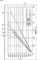
- FIG. 2 shows an example of the temperature-dependent correction amount corresponding to the temperature.
- the horizontal axis indicates the temperature [° C.]
- the vertical axis indicates the correction amount.
- the correction amount at 45 ° C. as the reference value is set to 1, and the correction amount is set to gradually increase as the temperature rises. On the contrary, the correction amount is set to decrease when the temperature falls below 45 ° C. as the reference value.
- the combined gain table 19 instead of holding the temperature-dependent correction amount corresponding to the temperature, a composite gain corresponding to the temperature calculated in advance may be held.
- the synthesizing unit 20 generates a WD image by synthesizing a result obtained by multiplying a predetermined pixel processed large pixel signal and a predetermined signal processed small pixel signal by a synthetic gain. For example, a large pixel signal is used until the large pixel signal is saturated from the lowest luminance of the subject, and a small pixel signal multiplied by the composite gain is used for luminance higher than the luminance at which the large pixel is saturated. Generate a WD image.
- a synthesis rate of 1 or less corresponding to the luminance is set, and a result obtained by multiplying a predetermined pixel processed large pixel signal by an addition rate, a predetermined signal processed small pixel signal, and a synthesis gain (1 ⁇ The result obtained by multiplying the composite rate is added to generate a WD image.
- FIG. 3 is a flowchart for explaining WD image generation processing by the image processing apparatus.
- step S1 the pixel unit 11 performs imaging according to the control from the imaging control unit 12, and outputs a large pixel signal and a small pixel signal.
- the large pixel signal is acquired by the large pixel signal processing unit 14, and the small pixel signal is acquired by the small pixel signal processing unit 16.
- step S ⁇ b> 2 the temperature detection unit 13 detects the temperature of the pixel unit 11 and notifies the large pixel signal processing unit 14, the small pixel signal processing unit 16, and the composite gain determination unit 18.
- step S ⁇ b> 3 the large pixel signal processing unit 14 performs predetermined signal processing corresponding to the temperature on the large pixel signal input from the pixel unit 11, and outputs the signal-processed large pixel signal to the combining unit 20.
- step S ⁇ b> 4 the small pixel signal processing unit 16 performs predetermined signal processing corresponding to the temperature on the small pixel signal input from the pixel unit 11, and outputs the signal-processed small pixel signal to the combining unit 20. .
- step S ⁇ b> 5 the combined gain determination unit 18 acquires a temperature-dependent correction amount corresponding to the temperature notified from the temperature detection unit 13 from the combined gain table 19.
- the composite gain determination unit 18 also includes the temperature-dependent correction amount, the exposure times of the large and small pixels notified from the imaging control unit 12, the minimum gain notified from the large pixel signal processing unit 14, and the small pixels.
- the combined gain is determined by applying the minimum gain notified from the signal processing unit 16 and the combined gain at 60 ° C. held in advance to the equation (1), and the determined combined gain is notified to the combining unit 20.
- step S6 the synthesizing unit 20 generates a WD image by synthesizing a result obtained by multiplying a predetermined pixel processed large pixel signal and a predetermined signal processed small pixel signal by a synthetic gain. This completes the WD image generation process.
- FIG. 4 shows a conventional method that does not take into account the temperature-dependent characteristics of large and small pixels at 45 ° C., which is a temperature reference value that can be assumed that there is no difference in temperature-dependent characteristics of large and small pixels.
- the change in the luminance of the subject indicates the change in the level of the pixel signal.
- solid lines RL, GL, and BL represent the R, G, and B components of the large pixel signal
- broken lines RS, GS, and BS represent the R, G, and B components of the small pixel signal multiplied by the combined gain, respectively. .
- the solid line RL and the broken line RS, the solid line GL and the broken line GS, the solid line BL and the broken line BS are connected without any step, and the pixel signal level with respect to the luminance change can maintain the linearity.
- FIG. 5 shows the luminance of a subject when a large pixel signal and a small pixel signal are synthesized by a conventional method in which the temperature-dependent characteristics of the large pixel and the small pixel are not considered at 105 ° C., which greatly exceeds the reference value of 45 ° C.
- the change in the pixel signal indicates the change in the level of the pixel signal.
- solid lines RL, GL, and BL represent the R, G, and B components of the large pixel signal
- broken lines RS, GS, and BS represent the R, G, and B components of the small pixel signal multiplied by the combined gain, respectively. .
- FIG. 6 shows the change in the luminance of the subject when the large pixel signal and the small pixel signal are synthesized by the above-described WD synthesis processing at 105 ° C., which greatly exceeds the reference value 45 ° C., and the change in the pixel signal level.
- solid lines RL, GL, and BL represent the R, G, and B components of the large pixel signal
- broken lines RS, GS, and BS represent the R, G, and B components of the small pixel signal multiplied by the combined gain, respectively. .
- the composite gain to be multiplied by the small pixel signal is determined corresponding to the temperature, so as shown in FIG.
- the solid line RL and the broken line RS, the solid line GL and the broken line GS, and the solid line BL and the broken line BS are smoothly connected as compared with FIG. 5, and the pixel signal level with respect to the luminance change can maintain the linearity. Therefore, it is possible to suppress image quality deterioration such as generation of false color near the joint.
- the pixel unit 11 in the image processing apparatus shown in FIG. 1 is composed of a solid-state image sensor such as a CMOS image sensor.
- components other than the pixel unit 11 in FIG. 1 are included in the solid-state image sensor. It may be configured. That is, you may comprise so that all the components shown by FIG. 1 may be included in a solid-state image sensor.
- the technology according to the present disclosure can be applied to various products.
- the technology according to the present disclosure may be applied to an endoscopic surgery system.
- FIG. 7 is a diagram illustrating an example of a schematic configuration of an endoscopic surgery system to which the technology (present technology) according to the present disclosure can be applied.
- FIG. 7 shows a state in which an operator (doctor) 11131 is performing an operation on a patient 11132 on a patient bed 11133 using an endoscopic operation system 11000.
- an endoscopic surgery system 11000 includes an endoscope 11100, other surgical instruments 11110 such as an insufflation tube 11111 and an energy treatment instrument 11112, and a support arm device 11120 that supports the endoscope 11100. And a cart 11200 on which various devices for endoscopic surgery are mounted.
- the endoscope 11100 includes a lens barrel 11101 in which a region having a predetermined length from the distal end is inserted into the body cavity of the patient 11132, and a camera head 11102 connected to the proximal end of the lens barrel 11101.
- a lens barrel 11101 in which a region having a predetermined length from the distal end is inserted into the body cavity of the patient 11132, and a camera head 11102 connected to the proximal end of the lens barrel 11101.
- an endoscope 11100 configured as a so-called rigid mirror having a rigid lens barrel 11101 is illustrated, but the endoscope 11100 may be configured as a so-called flexible mirror having a flexible lens barrel. Good.
- An opening into which the objective lens is fitted is provided at the tip of the lens barrel 11101.
- a light source device 11203 is connected to the endoscope 11100, and light generated by the light source device 11203 is guided to the tip of the lens barrel by a light guide extending inside the lens barrel 11101. Irradiation is performed toward the observation target in the body cavity of the patient 11132 through the lens.
- the endoscope 11100 may be a direct endoscope, a perspective mirror, or a side endoscope.
- An optical system and an image sensor are provided inside the camera head 11102, and reflected light (observation light) from the observation target is condensed on the image sensor by the optical system. Observation light is photoelectrically converted by the imaging element, and an electrical signal corresponding to the observation light, that is, an image signal corresponding to the observation image is generated.
- the image signal is transmitted to a camera control unit (CCU: Camera Control Unit) 11201 as RAW data.
- CCU Camera Control Unit
- the CCU 11201 is configured by a CPU (Central Processing Unit), a GPU (Graphics Processing Unit), and the like, and comprehensively controls operations of the endoscope 11100 and the display device 11202. Further, the CCU 11201 receives an image signal from the camera head 11102 and performs various kinds of image processing for displaying an image based on the image signal, such as development processing (demosaic processing), for example.
- a CPU Central Processing Unit
- GPU Graphics Processing Unit
- the display device 11202 displays an image based on an image signal subjected to image processing by the CCU 11201 under the control of the CCU 11201.
- the light source device 11203 is composed of a light source such as an LED (Light Emitting Diode), for example, and supplies irradiation light to the endoscope 11100 when photographing a surgical site or the like.
- a light source such as an LED (Light Emitting Diode), for example, and supplies irradiation light to the endoscope 11100 when photographing a surgical site or the like.
- the input device 11204 is an input interface for the endoscopic surgery system 11000.
- a user can input various information and instructions to the endoscopic surgery system 11000 via the input device 11204.
- the user inputs an instruction to change the imaging conditions (type of irradiation light, magnification, focal length, etc.) by the endoscope 11100.
- the treatment instrument control device 11205 controls the drive of the energy treatment instrument 11112 for tissue ablation, incision, blood vessel sealing, or the like.
- the pneumoperitoneum device 11206 passes gas into the body cavity via the pneumoperitoneum tube 11111.
- the recorder 11207 is an apparatus capable of recording various types of information related to surgery.
- the printer 11208 is a device that can print various types of information related to surgery in various formats such as text, images, or graphs.
- the light source device 11203 that supplies the irradiation light when the surgical site is imaged to the endoscope 11100 can be configured by, for example, a white light source configured by an LED, a laser light source, or a combination thereof.
- a white light source is configured by a combination of RGB laser light sources, the output intensity and output timing of each color (each wavelength) can be controlled with high accuracy. Therefore, the light source device 11203 adjusts the white balance of the captured image. It can be carried out.
- the driving of the light source device 11203 may be controlled so as to change the intensity of the output light every predetermined time. Synchronously with the timing of changing the intensity of the light, the drive of the image sensor of the camera head 11102 is controlled to acquire an image in a time-sharing manner, and the image is synthesized, so that high dynamic without so-called blackout and overexposure A range image can be generated.
- the light source device 11203 may be configured to be able to supply light of a predetermined wavelength band corresponding to special light observation.
- special light observation for example, by utilizing the wavelength dependence of light absorption in body tissue, the surface of the mucous membrane is irradiated by irradiating light in a narrow band compared to irradiation light (ie, white light) during normal observation.
- a so-called narrow band imaging is performed in which a predetermined tissue such as a blood vessel is imaged with high contrast.
- fluorescence observation may be performed in which an image is obtained by fluorescence generated by irradiating excitation light.
- the body tissue is irradiated with excitation light to observe fluorescence from the body tissue (autofluorescence observation), or a reagent such as indocyanine green (ICG) is locally administered to the body tissue and applied to the body tissue. It is possible to obtain a fluorescence image by irradiating excitation light corresponding to the fluorescence wavelength of the reagent.
- the light source device 11203 can be configured to be able to supply narrowband light and / or excitation light corresponding to such special light observation.
- FIG. 8 is a block diagram showing an example of the functional configuration of the camera head 11102 and the CCU 11201 shown in FIG.
- the camera head 11102 includes a lens unit 11401, an imaging unit 11402, a drive unit 11403, a communication unit 11404, and a camera head control unit 11405.
- the CCU 11201 includes a communication unit 11411, an image processing unit 11412, and a control unit 11413.
- the camera head 11102 and the CCU 11201 are connected to each other by a transmission cable 11400 so that they can communicate with each other.
- the lens unit 11401 is an optical system provided at a connection portion with the lens barrel 11101. Observation light taken from the tip of the lens barrel 11101 is guided to the camera head 11102 and enters the lens unit 11401.
- the lens unit 11401 is configured by combining a plurality of lenses including a zoom lens and a focus lens.
- the imaging unit 11402 includes an imaging element.
- One (so-called single plate type) image sensor may be included in the imaging unit 11402, or a plurality (so-called multi-plate type) may be used.
- image signals corresponding to RGB may be generated by each imaging element, and a color image may be obtained by combining them.
- the imaging unit 11402 may be configured to include a pair of imaging elements for acquiring right-eye and left-eye image signals corresponding to 3D (Dimensional) display. By performing the 3D display, the operator 11131 can more accurately grasp the depth of the living tissue in the surgical site.
- 3D 3D
- the imaging unit 11402 is not necessarily provided in the camera head 11102.
- the imaging unit 11402 may be provided inside the lens barrel 11101 immediately after the objective lens.
- the driving unit 11403 is configured by an actuator, and moves the zoom lens and the focus lens of the lens unit 11401 by a predetermined distance along the optical axis under the control of the camera head control unit 11405. Thereby, the magnification and the focus of the image captured by the imaging unit 11402 can be adjusted as appropriate.
- the communication unit 11404 is configured by a communication device for transmitting and receiving various types of information to and from the CCU 11201.
- the communication unit 11404 transmits the image signal obtained from the imaging unit 11402 as RAW data to the CCU 11201 via the transmission cable 11400.
- the communication unit 11404 receives a control signal for controlling driving of the camera head 11102 from the CCU 11201 and supplies the control signal to the camera head control unit 11405.
- the control signal includes, for example, information for designating the frame rate of the captured image, information for designating the exposure value at the time of imaging, and / or information for designating the magnification and focus of the captured image. Contains information about the condition.
- the imaging conditions such as the frame rate, exposure value, magnification, and focus may be appropriately specified by the user, or may be automatically set by the control unit 11413 of the CCU 11201 based on the acquired image signal. Good. In the latter case, a so-called AE (Auto Exposure) function, AF (Auto Focus) function, and AWB (Auto White Balance) function are mounted on the endoscope 11100.
- AE Auto Exposure
- AF Automatic Focus
- AWB Auto White Balance
- the camera head control unit 11405 controls driving of the camera head 11102 based on a control signal from the CCU 11201 received via the communication unit 11404.
- the communication unit 11411 is configured by a communication device for transmitting and receiving various types of information to and from the camera head 11102.
- the communication unit 11411 receives an image signal transmitted from the camera head 11102 via the transmission cable 11400.
- the communication unit 11411 transmits a control signal for controlling driving of the camera head 11102 to the camera head 11102.
- the image signal and the control signal can be transmitted by electrical communication, optical communication, or the like.
- the image processing unit 11412 performs various types of image processing on the image signal that is RAW data transmitted from the camera head 11102.
- the control unit 11413 performs various types of control related to imaging of the surgical site by the endoscope 11100 and display of a captured image obtained by imaging of the surgical site. For example, the control unit 11413 generates a control signal for controlling driving of the camera head 11102.
- control unit 11413 causes the display device 11202 to display a picked-up image showing the surgical part or the like based on the image signal subjected to the image processing by the image processing unit 11412.
- the control unit 11413 may recognize various objects in the captured image using various image recognition techniques.
- the control unit 11413 detects surgical tools such as forceps, specific biological parts, bleeding, mist when using the energy treatment tool 11112, and the like by detecting the shape and color of the edge of the object included in the captured image. Can be recognized.
- the control unit 11413 may display various types of surgery support information superimposed on the image of the surgical unit using the recognition result. Surgery support information is displayed in a superimposed manner and presented to the operator 11131, thereby reducing the burden on the operator 11131 and allowing the operator 11131 to proceed with surgery reliably.
- the transmission cable 11400 for connecting the camera head 11102 and the CCU 11201 is an electric signal cable corresponding to electric signal communication, an optical fiber corresponding to optical communication, or a composite cable thereof.
- communication is performed by wire using the transmission cable 11400.
- communication between the camera head 11102 and the CCU 11201 may be performed wirelessly.
- the technology according to the present disclosure can be applied to, for example, the endoscope 11100, the camera head 11102 (the imaging unit 11402), the CCU 11201 (the image processing unit 11412), and the like.
- the technology according to the present disclosure can be applied to various products.
- the technology according to the present disclosure is realized as a device that is mounted on any type of mobile body such as an automobile, an electric vehicle, a hybrid electric vehicle, a motorcycle, a bicycle, personal mobility, an airplane, a drone, a ship, and a robot. May be.
- FIG. 9 is a block diagram illustrating a schematic configuration example of a vehicle control system that is an example of a mobile control system to which the technology according to the present disclosure can be applied.
- the vehicle control system 12000 includes a plurality of electronic control units connected via a communication network 12001.
- the vehicle control system 12000 includes a drive system control unit 12010, a body system control unit 12020, a vehicle exterior information detection unit 12030, a vehicle interior information detection unit 12040, and an integrated control unit 12050.
- a microcomputer 12051, an audio image output unit 12052, and an in-vehicle network I / F (interface) 12053 are illustrated.
- the drive system control unit 12010 controls the operation of the device related to the drive system of the vehicle according to various programs.
- the drive system control unit 12010 includes a driving force generator for generating a driving force of a vehicle such as an internal combustion engine or a driving motor, a driving force transmission mechanism for transmitting the driving force to wheels, and a steering angle of the vehicle. It functions as a control device such as a steering mechanism that adjusts and a braking device that generates a braking force of the vehicle.
- the body system control unit 12020 controls the operation of various devices mounted on the vehicle body according to various programs.
- the body system control unit 12020 functions as a keyless entry system, a smart key system, a power window device, or a control device for various lamps such as a headlamp, a back lamp, a brake lamp, a blinker, or a fog lamp.
- the body control unit 12020 can be input with radio waves transmitted from a portable device that substitutes for a key or signals from various switches.
- the body system control unit 12020 receives input of these radio waves or signals, and controls a door lock device, a power window device, a lamp, and the like of the vehicle.
- the vehicle outside information detection unit 12030 detects information outside the vehicle on which the vehicle control system 12000 is mounted.
- the imaging unit 12031 is connected to the vehicle exterior information detection unit 12030.
- the vehicle exterior information detection unit 12030 causes the imaging unit 12031 to capture an image outside the vehicle and receives the captured image.
- the vehicle outside information detection unit 12030 may perform an object detection process or a distance detection process such as a person, a car, an obstacle, a sign, or a character on a road surface based on the received image.
- the imaging unit 12031 is an optical sensor that receives light and outputs an electrical signal corresponding to the amount of received light.
- the imaging unit 12031 can output an electrical signal as an image, or can output it as distance measurement information. Further, the light received by the imaging unit 12031 may be visible light or invisible light such as infrared rays.
- the vehicle interior information detection unit 12040 detects vehicle interior information.
- a driver state detection unit 12041 that detects a driver's state is connected to the in-vehicle information detection unit 12040.
- the driver state detection unit 12041 includes, for example, a camera that images the driver, and the vehicle interior information detection unit 12040 determines the degree of fatigue or concentration of the driver based on the detection information input from the driver state detection unit 12041. It may be calculated or it may be determined whether the driver is asleep.
- the microcomputer 12051 calculates a control target value of the driving force generator, the steering mechanism, or the braking device based on the information inside / outside the vehicle acquired by the vehicle outside information detection unit 12030 or the vehicle interior information detection unit 12040, and the drive system control unit A control command can be output to 12010.
- the microcomputer 12051 realizes an ADAS (Advanced Driver Assistance System) function including vehicle collision avoidance or impact mitigation, following traveling based on inter-vehicle distance, vehicle speed maintaining traveling, vehicle collision warning, or vehicle lane departure warning, etc. It is possible to perform cooperative control for the purpose.
- ADAS Advanced Driver Assistance System
- the microcomputer 12051 controls the driving force generator, the steering mechanism, the braking device, and the like based on the information around the vehicle acquired by the vehicle exterior information detection unit 12030 or the vehicle interior information detection unit 12040. It is possible to perform cooperative control for the purpose of automatic driving that autonomously travels without depending on the operation.
- the microcomputer 12051 can output a control command to the body system control unit 12020 based on information outside the vehicle acquired by the vehicle outside information detection unit 12030.
- the microcomputer 12051 controls the headlamp according to the position of the preceding vehicle or the oncoming vehicle detected by the outside information detection unit 12030, and performs cooperative control for the purpose of anti-glare, such as switching from a high beam to a low beam. It can be carried out.
- the sound image output unit 12052 transmits an output signal of at least one of sound and image to an output device capable of visually or audibly notifying information to a vehicle occupant or the outside of the vehicle.
- an audio speaker 12061, a display unit 12062, and an instrument panel 12063 are illustrated as output devices.
- the display unit 12062 may include at least one of an on-board display and a head-up display, for example.
- FIG. 10 is a diagram illustrating an example of the installation position of the imaging unit 12031.
- the vehicle 12100 includes imaging units 12101, 12102, 12103, 12104, and 12105 as the imaging unit 12031.
- the imaging units 12101, 12102, 12103, 12104, and 12105 are provided, for example, at positions such as a front nose, a side mirror, a rear bumper, a back door, and an upper part of a windshield in the vehicle interior of the vehicle 12100.
- the imaging unit 12101 provided in the front nose and the imaging unit 12105 provided in the upper part of the windshield in the vehicle interior mainly acquire an image in front of the vehicle 12100.
- the imaging units 12102 and 12103 provided in the side mirror mainly acquire an image of the side of the vehicle 12100.
- the imaging unit 12104 provided in the rear bumper or the back door mainly acquires an image behind the vehicle 12100.
- the forward images acquired by the imaging units 12101 and 12105 are mainly used for detecting a preceding vehicle or a pedestrian, an obstacle, a traffic light, a traffic sign, a lane, or the like.
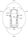
- FIG. 10 shows an example of the shooting range of the imaging units 12101 to 12104.
- the imaging range 12111 indicates the imaging range of the imaging unit 12101 provided in the front nose
- the imaging ranges 12112 and 12113 indicate the imaging ranges of the imaging units 12102 and 12103 provided in the side mirrors, respectively
- the imaging range 12114 The imaging range of the imaging part 12104 provided in the rear bumper or the back door is shown. For example, by superimposing the image data captured by the imaging units 12101 to 12104, an overhead image when the vehicle 12100 is viewed from above is obtained.
- At least one of the imaging units 12101 to 12104 may have a function of acquiring distance information.
- at least one of the imaging units 12101 to 12104 may be a stereo camera including a plurality of imaging elements, or may be an imaging element having pixels for phase difference detection.
- the microcomputer 12051 based on the distance information obtained from the imaging units 12101 to 12104, the distance to each three-dimensional object in the imaging range 12111 to 12114 and the temporal change in this distance (relative speed with respect to the vehicle 12100).
- a predetermined speed for example, 0 km / h or more
- the microcomputer 12051 can set an inter-vehicle distance to be secured in advance before the preceding vehicle, and can perform automatic brake control (including follow-up stop control), automatic acceleration control (including follow-up start control), and the like.
- automatic brake control including follow-up stop control
- automatic acceleration control including follow-up start control
- cooperative control for the purpose of autonomous driving or the like autonomously traveling without depending on the operation of the driver can be performed.
- the microcomputer 12051 converts the three-dimensional object data related to the three-dimensional object to other three-dimensional objects such as a two-wheeled vehicle, a normal vehicle, a large vehicle, a pedestrian, and a utility pole based on the distance information obtained from the imaging units 12101 to 12104. It can be classified and extracted and used for automatic avoidance of obstacles.
- the microcomputer 12051 identifies obstacles around the vehicle 12100 as obstacles that are visible to the driver of the vehicle 12100 and obstacles that are difficult to see.
- the microcomputer 12051 determines the collision risk indicating the risk of collision with each obstacle, and when the collision risk is equal to or higher than the set value and there is a possibility of collision, the microcomputer 12051 is connected via the audio speaker 12061 or the display unit 12062. By outputting an alarm to the driver and performing forced deceleration or avoidance steering via the drive system control unit 12010, driving assistance for collision avoidance can be performed.
- At least one of the imaging units 12101 to 12104 may be an infrared camera that detects infrared rays.
- the microcomputer 12051 can recognize a pedestrian by determining whether a pedestrian is present in the captured images of the imaging units 12101 to 12104. Such pedestrian recognition is, for example, whether or not the user is a pedestrian by performing a pattern matching process on a sequence of feature points indicating the outline of an object and a procedure for extracting feature points in the captured images of the imaging units 12101 to 12104 as infrared cameras. It is carried out by the procedure for determining.
- the audio image output unit 12052 When the microcomputer 12051 determines that there is a pedestrian in the captured images of the imaging units 12101 to 12104 and recognizes the pedestrian, the audio image output unit 12052 has a rectangular contour line for emphasizing the recognized pedestrian.
- the display unit 12062 is controlled so as to be superimposed and displayed.
- voice image output part 12052 may control the display part 12062 so that the icon etc. which show a pedestrian may be displayed on a desired position.
- the present technology can also have the following configurations.
- a first acquisition unit for acquiring a first pixel signal output from the first pixel;
- a second acquisition unit that acquires a second pixel signal output from a second pixel that is smaller in size than the first pixel;
- a temperature detector for detecting the temperature;
- a combined gain determining unit that determines a combined gain corresponding to the detected temperature;
- An image processing apparatus comprising: a synthesis unit that synthesizes the first pixel signal and the second pixel signal multiplied by the synthesis gain.
- the image processing apparatus according to (1) further including a pixel unit in which a plurality of the first pixels and a plurality of the second pixels are arranged.
- the image processing apparatus according to (1) or (2), wherein the first pixel and the second pixel have different temperature dependency characteristics.
- the composite gain determination unit acquires the temperature-dependent correction amount corresponding to the detected temperature from the table, and calculates the composite gain using the acquired temperature-dependent correction amount.
- the image processing apparatus according to any one of 3).
- OB optical black
- the solid-state imaging device is A pixel portion in which a plurality of first pixels and a plurality of second pixels smaller in size than the first pixels are disposed; A first acquisition unit that acquires a first pixel signal output from the first pixel; A second acquisition unit for acquiring a second pixel signal output from the second pixel; A temperature detector for detecting the temperature; A combined gain determining unit that determines a combined gain corresponding to the detected temperature; An electronic apparatus comprising: a combining unit that combines the first pixel signal and the second pixel signal multiplied by the combined gain.
Landscapes
- Health & Medical Sciences (AREA)
- Life Sciences & Earth Sciences (AREA)
- Engineering & Computer Science (AREA)
- Surgery (AREA)
- Signal Processing (AREA)
- Multimedia (AREA)
- Physics & Mathematics (AREA)
- Optics & Photonics (AREA)
- Heart & Thoracic Surgery (AREA)
- Public Health (AREA)
- Pathology (AREA)
- Biomedical Technology (AREA)
- Nuclear Medicine, Radiotherapy & Molecular Imaging (AREA)
- Medical Informatics (AREA)
- Molecular Biology (AREA)
- Animal Behavior & Ethology (AREA)
- General Health & Medical Sciences (AREA)
- Radiology & Medical Imaging (AREA)
- Veterinary Medicine (AREA)
- Biophysics (AREA)
- Computing Systems (AREA)
- Theoretical Computer Science (AREA)
- Microelectronics & Electronic Packaging (AREA)
- Studio Devices (AREA)
- Color Television Image Signal Generators (AREA)
- Transforming Light Signals Into Electric Signals (AREA)
Abstract
本技術は、大画素の画素信号と小画素の画素信号を合成してWD画像を生成するに際し、WD画像の画質劣化を抑制することができるようにする画像処理装置、画像処理方法、および電子機器に関する。 本技術の第1の側面である画像処理装置は、第1の画素から出力された第1の画素信号を取得する第1の取得部と、前記第1の画素よりもサイズが小さい第2の画素から出力された第2の画素信号を取得する第2の取得部と、温度を検出する温度検出部と、検出された前記温度に対応する合成ゲインを決定する合成ゲイン決定部と、前記第1の画素信号と、前記合成ゲインを乗算した前記第2の画素信号とを合成する合成部とを備える。本技術は、例えば、CMOSイメージセンサに適用できる。
Description
本技術は、画像処理装置、画像処理方法、および電子機器に関し、特に、受光感度が異なる画素から出力される画素信号を合成してWD(ワイドダイナミックレンジ)画像を生成するようにした画像処理装置、画像処理方法、および電子機器に関する。
従来、WD画像を生成する方法として、CMOS(complementary metal-oxide semiconductor)イメージセンサなどの画素アレイ上に感度の異なる第1の画素と第2の画素を設け、それぞれの出力から成る第1の画像と第2の画像を合成する方法が知られている。
ここで、感度が異なる画素を設ける方法としては、例えば、露光時間が長い画素(以下、長蓄画素と称する)と短い画素(以下、短蓄画素と称する)を設けたり、PD(フォトダイオード)等の光電変換部のサイズが大きい画素(以下、大画素と称する)と小さい画素(以下、小画素と称する)を設けたりする方法がある(例えば、特許文献1参照)。
長蓄画素と短蓄画素を設ける方法では、両画素の構造が同一であり、両画素の温度に依存し得る様々な特性が共通であるため、両画素の画素信号を合成するに際しても温度を考慮して合成する必要は生じない。
一方、大画素と小画素を設ける方法では、両画素の構造が異なる。すなわち、両画素のPD等の光電変換部のサイズが異なり、両画素の温度に依存して変化する各種の特性が異なる。ここで、温度に依存して変化する各種の特性としては、感度特性、飽和電荷量Qs、変換効率、白点発生特性、黒点発生特性等を挙げることができる。以下、これらを一括して温度依存特性と称する。
したがって、大画素の画素信号と小画素の画素信号を合成する場合、上述した温度依存特性を考慮しないと、温度によっては大画素の画素信号と小画素の画素信号の繋ぎ目に段差が生じたり、被写体の輝度の変化に対する画素信号の変化がリニアリティを保てなかったりすることが起こり得る。このよう場合、生成されたWD画像上に偽色が発生する等の画質劣化が生じてしまう。
本技術はこのような状況に鑑みてなされたものであり、大画素の画素信号と小画素の画素信号を合成してWD画像を生成するに際し、WD画像の画質劣化を抑制できるようにするものである。
本技術の第1の側面である画像処理装置は、第1の画素から出力された第1の画素信号を取得する第1の取得部と、前記第1の画素よりもサイズが小さい第2の画素から出力された第2の画素信号を取得する第2の取得部と、温度を検出する温度検出部と、検出された前記温度に対応する合成ゲインを決定する合成ゲイン決定部と、前記第1の画素信号と、前記合成ゲインを乗算した前記第2の画素信号とを合成する合成部とを備える。
本技術の第1の側面である画像処理方法は、画像処理装置の画像処理方法において、前記画像処理装置による、第1の画素から出力された第1の画素信号を取得する第1の取得ステップと、前記第1の画素よりもサイズが小さい第2の画素から出力された第2の画素信号を取得する第2の取得ステップと、温度を検出する温度検出ステップと、検出された前記温度に対応する合成ゲインを決定する合成ゲイン決定ステップと、前記第1の画素信号と、前記合成ゲインを乗算した前記第2の画素信号とを合成する合成ステップとを含む。
本技術の第2の側面である電子機器は、固体撮像素子が搭載された電子機器において、前記固体撮像素子は、複数の第1の画素と前記第1の画素よりもサイズが小さい複数の第2の画素が配置されている画素部と、前記第1の画素から出力された第1の画素信号を取得する第1の取得部と、前記第2の画素から出力された第2の画素信号を取得する第2の取得部と、温度を検出する温度検出部と、検出された前記温度に対応する合成ゲインを決定する合成ゲイン決定部と、前記第1の画素信号と、前記合成ゲインを乗算した前記第2の画素信号とを合成する合成部とを備える。
本技術の第1および第2の側面においては、第1の画素から出力された第1の画素信号が取得され、前記第1の画素よりもサイズが小さい第2の画素から出力された第2の画素信号が取得され、温度が検出され、検出された前記温度に対応する合成ゲインが決定され、前記第1の画素信号と、前記合成ゲインを乗算した前記第2の画素信号とが合成される。
本技術の第1の一側面によれば、大画素の画素信号と小画素の画素信号を合成したWD画像の画質劣化を抑制できる。
以下、本技術を実施するための最良の形態(以下、実施の形態と称する)について、図面を参照しながら詳細に説明する。
<本技術の実施の形態である画像処理装置の構成例>
図1は、本技術の実施の形態である画像処理装置の構成例を示すブロック図である。
図1は、本技術の実施の形態である画像処理装置の構成例を示すブロック図である。
該画像処理装置は、画素部11、撮像制御部12、温度検出部13、大画素信号処理部14、大画素用テーブル15、小画素信号処理部16、小画素用テーブル17、合成ゲイン決定部18、合成ゲインテーブル19、および合成部20を有する。
画素部11は、受光感度が異なる大画素と小画素が所定の規則に従って配列されたCMOSイメージセンサ等の固体撮像素子から成る。なお、大画素と小画素は、R(赤),G(緑),B(青)のいずれかの色のカラーフィルタ、または可視光以外の波長帯を取得するためのフィルタのいずれかを有しており、R,G,Bのいずれかの色成分、もしくは可視光以外の波長帯で構成される画素信号を生成する。画素部11は、大画素の画素信号を大画素信号処理部14に出力し、小画素の画素信号を小画素信号処理部16に出力する。以下、大画素の画素信号を大画素信号、小画素の画素信号を小画素信号と称する。
撮像制御部12は、画素部11の動作を制御する。特に、撮像制御部12は、画素部11の大画素の露光時間と、小画素の露光時間を制御して、それぞれを合成ゲイン決定部18に通知する。
温度検出部13は、画素部11の温度を検出して大画素信号処理部14、小画素信号処理部16、および合成ゲイン決定部18に通知する。
大画素信号処理部14は、画素部11から入力される大画素信号に対し、温度に対応した所定の信号処理を行い、信号処理済の大画素信号を合成部20に出力する。
例えば、大画素信号処理部14は、温度の変化に依存して変化するOB(オプティカルブラック)クランプ値を大画素用テーブル15から取得し、大画素信号にOBクランプ処理を行う。また、例えば、大画素信号処理部14は、温度の変化に依存して変化する飽和信号量Qsに対応するミニマムゲインを大画素用テーブル15から取得し、取得したミニマムゲインを大画素信号に乗算する。
さらに、大画素信号処理部14は、大画素信号に乗算したミニマムゲインを合成ゲイン決定部18に通知する。
大画素用テーブル15には、大画素信号処理部14における信号処理で用いられる、大画素と小画素の温度依存特性に違いがないと想定できる45℃を基準とする温度依存の各種パラメータがテーブルとして予め保持されている。なお、テーブルの代わりに、温度依存の各種パラメータを、温度に対する関数として保持するようにしてもよい。
小画素信号処理部16は、画素部11から入力される小画素信号に対し、温度に対応した所定の信号処理を行い、信号処理済の大画素信号を合成部20に出力する。
例えば、小画素信号処理部16は、温度の変化に依存して変化するOBクランプ値を小画素用テーブル17から取得し、小画素信号にOBクランプ処理を行う。また、例えば、小画素信号処理部16は、温度の変化に依存して変化する飽和信号量Qsに対応するミニマムゲインを小画素用テーブル17から取得し、取得したミニマムゲインを小画素信号に乗算する。
さらに、小画素信号処理部16は、小画素信号に乗算したミニマムゲインを合成ゲイン決定部18に通知する。
小画素用テーブル17には、小画素信号処理部16における信号処理で用いられる、大画素と小画素の温度依存特性に違いがないと想定できる45℃を基準とする温度依存の各種パラメータがテーブルとして予め保持されている。なお、テーブルの代わりに、温度依存の各種パラメータを、温度に対する関数として保持するようにしてもよい。
合成ゲイン決定部18は、温度検出部13から通知される温度に対応する、R,G,Bの色成分毎に異なる温度依存補正量を合成ゲインテーブル19から取得する。また、合成ゲイン決定部18は、温度依存補正量と、撮像制御部12から通知される大画素と小画素それぞれの露光時間と、大画素信号処理部14から通知されるミニマムゲインと、小画素信号処理部16から通知されるミニマムゲインと、予め保持する45℃時の合成ゲインを次式(1)に適用することにより、色成分毎の合成ゲインを決定し、決定した合成ゲインを合成部20に通知する。
合成ゲイン=45℃時の合成ゲイン×(大画素の露光時間/小画素の露光時間)×(大画素のミニマムゲイン/大画素のミニマムゲイン)×温度依存補正量
・・・(1)
合成ゲイン=45℃時の合成ゲイン×(大画素の露光時間/小画素の露光時間)×(大画素のミニマムゲイン/大画素のミニマムゲイン)×温度依存補正量
・・・(1)
合成ゲインテーブル19には、温度に対応する適切な値が求められている温度依存補正量がテーブルとして予め保持されている。
図2は、温度に対応する温度依存補正量の一例を示している。同図の横軸は温度[℃]、縦軸は補正量を示している。同図においては、基準値とする45℃における補正量が1とされており、温度が上昇するにしたがって補正量も徐々に上昇するように設定されている。反対に、基準値とする45℃よりも温度が低下すると補正量も低下するように設定されている。
なお、大画素の露光時間、小画素の露光時間、大画素のミニマムゲイン、および大画素のミニマムゲインが固定値であったり、温度に依存する変数であったりする場合、合成ゲインテーブル19に、温度に対応する温度依存補正量を保持させる代わりに、予め算出した温度に対応する合成ゲインを保持させるようにしてもよい。
合成部20は、所定の信号処理済の大画素信号と、所定の信号処理済の小画素信号に合成ゲインを乗算した結果を合成してWD画像を生成する。例えば、被写体の輝度が低い方から大画素信号が飽和するまでは大画素信号を採用し、大画素が飽和した輝度以上の輝度においては、合成ゲインを乗算した小画素信号を採用するようにしてWD画像を生成する。また例えば、輝度に対応した1以下の合成率を設定し、所定の信号処理済の大画素信号に加算率を乗算した結果と、所定の信号処理済の小画素信号に合成ゲインと(1-合成率)を乗算した結果とを加算してWD画像を生成する。
<本技術の実施の形態である画像処理装置によるWD画像生成処理>
図3は、該画像処理装置によるWD画像生成処理を説明するフローチャートである。
図3は、該画像処理装置によるWD画像生成処理を説明するフローチャートである。
ステップS1において、画素部11が撮像制御部12からの制御に従って撮像を行い、大画素信号および小画素信号を出力する。大画素信号は大画素信号処理部14に取得され、小画素信号は小画素信号処理部16に取得される。ステップS2において、温度検出部13は、画素部11の温度を検出して大画素信号処理部14、小画素信号処理部16、および合成ゲイン決定部18に通知する。
ステップS3において、大画素信号処理部14は、画素部11から入力された大画素信号に対し、温度に対応した所定の信号処理を行い、信号処理済の大画素信号を合成部20に出力する。ステップS4において、小画素信号処理部16は、画素部11から入力された小画素信号に対し、温度に対応した所定の信号処理を行い、信号処理済の小画素信号を合成部20に出力する。
ステップS5において、合成ゲイン決定部18は、温度検出部13から通知される温度に対応する温度依存補正量を合成ゲインテーブル19から取得する。また、合成ゲイン決定部18は、温度依存補正量と、撮像制御部12から通知される大画素と小画素それぞれの露光時間と、大画素信号処理部14から通知されるミニマムゲインと、小画素信号処理部16から通知されるミニマムゲインと、予め保持する60℃時の合成ゲインを式(1)に適用することにより合成ゲインを決定し、決定した合成ゲインを合成部20に通知する。
ステップS6において、合成部20は、所定の信号処理済の大画素信号と、所定の信号処理済の小画素信号に合成ゲインを乗算した結果を合成してWD画像を生成する。以上で、WD画像生成処理は終了される。
<本技術の実施の形態である画像処理装置によるWD画像生成処理の効果>
上述したWD画像生成処理による効果について説明する。
上述したWD画像生成処理による効果について説明する。
図4は、大画素と小画素の温度依存特性に違いがないと想定できる温度の基準値とする45℃において、大画素と小画素の温度依存特性が考慮されていない従来の方法により、大画素信号と小画素信号を合成した場合における被写体の輝度の変化を画素信号のレベルの変化を示している。同図において、実線RL,GL,BLはそれぞれ大画素信号のR,G,B成分を表し、破線RS,GS,BSはそれぞれ合成ゲインを乗算した小画素信号のR,G,B成分を表す。
なお、45℃においてWD画像生成処理により大画素信号と小画素信号を合成した場合も結果を図4と同様になる。
すなわち、実線RLと破線RS、実線GLと破線GS、実線BLと破線BSがそれぞれ段差無く繋がり、輝度変化に対する画素信号レベルがリニアリティを保つことができる。
図5は、基準値45℃を大きく超えた105℃において、大画素と小画素の温度依存特性が考慮されていない従来の方法により、大画素信号と小画素信号を合成した場合における被写体の輝度の変化を画素信号のレベルの変化を示している。同図において、実線RL,GL,BLはそれぞれ大画素信号のR,G,B成分を表し、破線RS,GS,BSはそれぞれ合成ゲインを乗算した小画素信号のR,G,B成分を表す。
105℃の場合、大画素と小画素の温度依存特性に差異が生じるので、図5に示されるように、実線RLと破線RS、実線GLと破線GS、実線BLと破線BSがそれぞれうまく繋がらず、繋ぎ目付近で偽色が発生する等の画質劣化が発生してしまう。
図6は、基準値45℃を大きく超えた105℃において、上述したWD合成処理により、大画素信号と小画素信号を合成した場合における被写体の輝度の変化を画素信号のレベルの変化を示している。同図において、実線RL,GL,BLはそれぞれ大画素信号のR,G,B成分を表し、破線RS,GS,BSはそれぞれ合成ゲインを乗算した小画素信号のR,G,B成分を表す。
105℃の場合、大画素と小画素の温度依存特性に差異が生じているものの、小画素信号の乗算する合成ゲインが温度に対応して決定されているので、図6に示されるように、実線RLと破線RS、実線GLと破線GS、実線BLと破線BSがそれぞれ、図5に比較して滑らかに繋がり、輝度変化に対する画素信号レベルがリニアリティを保つことができる。したがって、繋ぎ目付近での偽色発生等の画質劣化を抑制することができる。
<変形例>
上述した説明では、図1に示された画像処理装置における画素部11をCMOSイメージセンサ等の固体撮像素子から成るとしたが、図1における画素部11以外の構成要素を固体撮像素子に含めて構成してもよい。すなわち、図1に示された全ての構成要素が固体撮像素子に含まれるように構成してもよい。
上述した説明では、図1に示された画像処理装置における画素部11をCMOSイメージセンサ等の固体撮像素子から成るとしたが、図1における画素部11以外の構成要素を固体撮像素子に含めて構成してもよい。すなわち、図1に示された全ての構成要素が固体撮像素子に含まれるように構成してもよい。
<内視鏡手術システムへの応用例>
本開示に係る技術(本技術)は、様々な製品へ応用することができる。例えば、本開示に係る技術は、内視鏡手術システムに適用されてもよい。
本開示に係る技術(本技術)は、様々な製品へ応用することができる。例えば、本開示に係る技術は、内視鏡手術システムに適用されてもよい。
図7は、本開示に係る技術(本技術)が適用され得る内視鏡手術システムの概略的な構成の一例を示す図である。
図7では、術者(医師)11131が、内視鏡手術システム11000を用いて、患者ベッド11133上の患者11132に手術を行っている様子が図示されている。図示するように、内視鏡手術システム11000は、内視鏡11100と、気腹チューブ11111やエネルギー処置具11112等の、その他の術具11110と、内視鏡11100を支持する支持アーム装置11120と、内視鏡下手術のための各種の装置が搭載されたカート11200と、から構成される。
内視鏡11100は、先端から所定の長さの領域が患者11132の体腔内に挿入される鏡筒11101と、鏡筒11101の基端に接続されるカメラヘッド11102と、から構成される。図示する例では、硬性の鏡筒11101を有するいわゆる硬性鏡として構成される内視鏡11100を図示しているが、内視鏡11100は、軟性の鏡筒を有するいわゆる軟性鏡として構成されてもよい。
鏡筒11101の先端には、対物レンズが嵌め込まれた開口部が設けられている。内視鏡11100には光源装置11203が接続されており、当該光源装置11203によって生成された光が、鏡筒11101の内部に延設されるライトガイドによって当該鏡筒の先端まで導光され、対物レンズを介して患者11132の体腔内の観察対象に向かって照射される。なお、内視鏡11100は、直視鏡であってもよいし、斜視鏡又は側視鏡であってもよい。
カメラヘッド11102の内部には光学系及び撮像素子が設けられており、観察対象からの反射光(観察光)は当該光学系によって当該撮像素子に集光される。当該撮像素子によって観察光が光電変換され、観察光に対応する電気信号、すなわち観察像に対応する画像信号が生成される。当該画像信号は、RAWデータとしてカメラコントロールユニット(CCU: Camera Control Unit)11201に送信される。
CCU11201は、CPU(Central Processing Unit)やGPU(Graphics Processing Unit)等によって構成され、内視鏡11100及び表示装置11202の動作を統括的に制御する。さらに、CCU11201は、カメラヘッド11102から画像信号を受け取り、その画像信号に対して、例えば現像処理(デモザイク処理)等の、当該画像信号に基づく画像を表示するための各種の画像処理を施す。
表示装置11202は、CCU11201からの制御により、当該CCU11201によって画像処理が施された画像信号に基づく画像を表示する。
光源装置11203は、例えばLED(Light Emitting Diode)等の光源から構成され、術部等を撮影する際の照射光を内視鏡11100に供給する。
入力装置11204は、内視鏡手術システム11000に対する入力インタフェースである。ユーザは、入力装置11204を介して、内視鏡手術システム11000に対して各種の情報の入力や指示入力を行うことができる。例えば、ユーザは、内視鏡11100による撮像条件(照射光の種類、倍率及び焦点距離等)を変更する旨の指示等を入力する。
処置具制御装置11205は、組織の焼灼、切開又は血管の封止等のためのエネルギー処置具11112の駆動を制御する。気腹装置11206は、内視鏡11100による視野の確保及び術者の作業空間の確保の目的で、患者11132の体腔を膨らめるために、気腹チューブ11111を介して当該体腔内にガスを送り込む。レコーダ11207は、手術に関する各種の情報を記録可能な装置である。プリンタ11208は、手術に関する各種の情報を、テキスト、画像又はグラフ等各種の形式で印刷可能な装置である。
なお、内視鏡11100に術部を撮影する際の照射光を供給する光源装置11203は、例えばLED、レーザ光源又はこれらの組み合わせによって構成される白色光源から構成することができる。RGBレーザ光源の組み合わせにより白色光源が構成される場合には、各色(各波長)の出力強度及び出力タイミングを高精度に制御することができるため、光源装置11203において撮像画像のホワイトバランスの調整を行うことができる。また、この場合には、RGBレーザ光源それぞれからのレーザ光を時分割で観察対象に照射し、その照射タイミングに同期してカメラヘッド11102の撮像素子の駆動を制御することにより、RGBそれぞれに対応した画像を時分割で撮像することも可能である。当該方法によれば、当該撮像素子にカラーフィルタを設けなくても、カラー画像を得ることができる。
また、光源装置11203は、出力する光の強度を所定の時間ごとに変更するようにその駆動が制御されてもよい。その光の強度の変更のタイミングに同期してカメラヘッド11102の撮像素子の駆動を制御して時分割で画像を取得し、その画像を合成することにより、いわゆる黒つぶれ及び白とびのない高ダイナミックレンジの画像を生成することができる。
また、光源装置11203は、特殊光観察に対応した所定の波長帯域の光を供給可能に構成されてもよい。特殊光観察では、例えば、体組織における光の吸収の波長依存性を利用して、通常の観察時における照射光(すなわち、白色光)に比べて狭帯域の光を照射することにより、粘膜表層の血管等の所定の組織を高コントラストで撮影する、いわゆる狭帯域光観察(Narrow Band Imaging)が行われる。あるいは、特殊光観察では、励起光を照射することにより発生する蛍光により画像を得る蛍光観察が行われてもよい。蛍光観察では、体組織に励起光を照射し当該体組織からの蛍光を観察すること(自家蛍光観察)、又はインドシアニングリーン(ICG)等の試薬を体組織に局注するとともに当該体組織にその試薬の蛍光波長に対応した励起光を照射し蛍光像を得ること等を行うことができる。光源装置11203は、このような特殊光観察に対応した狭帯域光及び/又は励起光を供給可能に構成され得る。
図8は、図7に示すカメラヘッド11102及びCCU11201の機能構成の一例を示すブロック図である。
カメラヘッド11102は、レンズユニット11401と、撮像部11402と、駆動部11403と、通信部11404と、カメラヘッド制御部11405と、を有する。CCU11201は、通信部11411と、画像処理部11412と、制御部11413と、を有する。カメラヘッド11102とCCU11201とは、伝送ケーブル11400によって互いに通信可能に接続されている。
レンズユニット11401は、鏡筒11101との接続部に設けられる光学系である。鏡筒11101の先端から取り込まれた観察光は、カメラヘッド11102まで導光され、当該レンズユニット11401に入射する。レンズユニット11401は、ズームレンズ及びフォーカスレンズを含む複数のレンズが組み合わされて構成される。
撮像部11402は、撮像素子で構成される。撮像部11402を構成する撮像素子は、1つ(いわゆる単板式)であってもよいし、複数(いわゆる多板式)であってもよい。撮像部11402が多板式で構成される場合には、例えば各撮像素子によってRGBそれぞれに対応する画像信号が生成され、それらが合成されることによりカラー画像が得られてもよい。あるいは、撮像部11402は、3D(Dimensional)表示に対応する右目用及び左目用の画像信号をそれぞれ取得するための1対の撮像素子を有するように構成されてもよい。3D表示が行われることにより、術者11131は術部における生体組織の奥行きをより正確に把握することが可能になる。なお、撮像部11402が多板式で構成される場合には、各撮像素子に対応して、レンズユニット11401も複数系統設けられ得る。
また、撮像部11402は、必ずしもカメラヘッド11102に設けられなくてもよい。例えば、撮像部11402は、鏡筒11101の内部に、対物レンズの直後に設けられてもよい。
駆動部11403は、アクチュエータによって構成され、カメラヘッド制御部11405からの制御により、レンズユニット11401のズームレンズ及びフォーカスレンズを光軸に沿って所定の距離だけ移動させる。これにより、撮像部11402による撮像画像の倍率及び焦点が適宜調整され得る。
通信部11404は、CCU11201との間で各種の情報を送受信するための通信装置によって構成される。通信部11404は、撮像部11402から得た画像信号をRAWデータとして伝送ケーブル11400を介してCCU11201に送信する。
また、通信部11404は、CCU11201から、カメラヘッド11102の駆動を制御するための制御信号を受信し、カメラヘッド制御部11405に供給する。当該制御信号には、例えば、撮像画像のフレームレートを指定する旨の情報、撮像時の露出値を指定する旨の情報、並びに/又は撮像画像の倍率及び焦点を指定する旨の情報等、撮像条件に関する情報が含まれる。
なお、上記のフレームレートや露出値、倍率、焦点等の撮像条件は、ユーザによって適宜指定されてもよいし、取得された画像信号に基づいてCCU11201の制御部11413によって自動的に設定されてもよい。後者の場合には、いわゆるAE(Auto Exposure)機能、AF(Auto Focus)機能及びAWB(Auto White Balance)機能が内視鏡11100に搭載されていることになる。
カメラヘッド制御部11405は、通信部11404を介して受信したCCU11201からの制御信号に基づいて、カメラヘッド11102の駆動を制御する。
通信部11411は、カメラヘッド11102との間で各種の情報を送受信するための通信装置によって構成される。通信部11411は、カメラヘッド11102から、伝送ケーブル11400を介して送信される画像信号を受信する。
また、通信部11411は、カメラヘッド11102に対して、カメラヘッド11102の駆動を制御するための制御信号を送信する。画像信号や制御信号は、電気通信や光通信等によって送信することができる。
画像処理部11412は、カメラヘッド11102から送信されたRAWデータである画像信号に対して各種の画像処理を施す。
制御部11413は、内視鏡11100による術部等の撮像、及び、術部等の撮像により得られる撮像画像の表示に関する各種の制御を行う。例えば、制御部11413は、カメラヘッド11102の駆動を制御するための制御信号を生成する。
また、制御部11413は、画像処理部11412によって画像処理が施された画像信号に基づいて、術部等が映った撮像画像を表示装置11202に表示させる。この際、制御部11413は、各種の画像認識技術を用いて撮像画像内における各種の物体を認識してもよい。例えば、制御部11413は、撮像画像に含まれる物体のエッジの形状や色等を検出することにより、鉗子等の術具、特定の生体部位、出血、エネルギー処置具11112の使用時のミスト等を認識することができる。制御部11413は、表示装置11202に撮像画像を表示させる際に、その認識結果を用いて、各種の手術支援情報を当該術部の画像に重畳表示させてもよい。手術支援情報が重畳表示され、術者11131に提示されることにより、術者11131の負担を軽減することや、術者11131が確実に手術を進めることが可能になる。
カメラヘッド11102及びCCU11201を接続する伝送ケーブル11400は、電気信号の通信に対応した電気信号ケーブル、光通信に対応した光ファイバ、又はこれらの複合ケーブルである。
ここで、図示する例では、伝送ケーブル11400を用いて有線で通信が行われていたが、カメラヘッド11102とCCU11201との間の通信は無線で行われてもよい。
以上、本開示に係る技術が適用され得る内視鏡手術システムの一例について説明した。本開示に係る技術は、以上説明した構成のうち、例えば、内視鏡11100や、カメラヘッド11102(の撮像部11402)、CCU11201(の画像処理部11412)等)に適用され得る。
<移動体への応用例>
本開示に係る技術(本技術)は、様々な製品へ応用することができる。例えば、本開示に係る技術は、自動車、電気自動車、ハイブリッド電気自動車、自動二輪車、自転車、パーソナルモビリティ、飛行機、ドローン、船舶、ロボット等のいずれかの種類の移動体に搭載される装置として実現されてもよい。
本開示に係る技術(本技術)は、様々な製品へ応用することができる。例えば、本開示に係る技術は、自動車、電気自動車、ハイブリッド電気自動車、自動二輪車、自転車、パーソナルモビリティ、飛行機、ドローン、船舶、ロボット等のいずれかの種類の移動体に搭載される装置として実現されてもよい。
図9は、本開示に係る技術が適用され得る移動体制御システムの一例である車両制御システムの概略的な構成例を示すブロック図である。
車両制御システム12000は、通信ネットワーク12001を介して接続された複数の電子制御ユニットを備える。図9に示した例では、車両制御システム12000は、駆動系制御ユニット12010、ボディ系制御ユニット12020、車外情報検出ユニット12030、車内情報検出ユニット12040、及び統合制御ユニット12050を備える。また、統合制御ユニット12050の機能構成として、マイクロコンピュータ12051、音声画像出力部12052、及び車載ネットワークI/F(interface)12053が図示されている。
駆動系制御ユニット12010は、各種プログラムにしたがって車両の駆動系に関連する装置の動作を制御する。例えば、駆動系制御ユニット12010は、内燃機関又は駆動用モータ等の車両の駆動力を発生させるための駆動力発生装置、駆動力を車輪に伝達するための駆動力伝達機構、車両の舵角を調節するステアリング機構、及び、車両の制動力を発生させる制動装置等の制御装置として機能する。
ボディ系制御ユニット12020は、各種プログラムにしたがって車体に装備された各種装置の動作を制御する。例えば、ボディ系制御ユニット12020は、キーレスエントリシステム、スマートキーシステム、パワーウィンドウ装置、あるいは、ヘッドランプ、バックランプ、ブレーキランプ、ウィンカー又はフォグランプ等の各種ランプの制御装置として機能する。この場合、ボディ系制御ユニット12020には、鍵を代替する携帯機から発信される電波又は各種スイッチの信号が入力され得る。ボディ系制御ユニット12020は、これらの電波又は信号の入力を受け付け、車両のドアロック装置、パワーウィンドウ装置、ランプ等を制御する。
車外情報検出ユニット12030は、車両制御システム12000を搭載した車両の外部の情報を検出する。例えば、車外情報検出ユニット12030には、撮像部12031が接続される。車外情報検出ユニット12030は、撮像部12031に車外の画像を撮像させるとともに、撮像された画像を受信する。車外情報検出ユニット12030は、受信した画像に基づいて、人、車、障害物、標識又は路面上の文字等の物体検出処理又は距離検出処理を行ってもよい。
撮像部12031は、光を受光し、その光の受光量に応じた電気信号を出力する光センサである。撮像部12031は、電気信号を画像として出力することもできるし、測距の情報として出力することもできる。また、撮像部12031が受光する光は、可視光であっても良いし、赤外線等の非可視光であっても良い。
車内情報検出ユニット12040は、車内の情報を検出する。車内情報検出ユニット12040には、例えば、運転者の状態を検出する運転者状態検出部12041が接続される。運転者状態検出部12041は、例えば運転者を撮像するカメラを含み、車内情報検出ユニット12040は、運転者状態検出部12041から入力される検出情報に基づいて、運転者の疲労度合い又は集中度合いを算出してもよいし、運転者が居眠りをしていないかを判別してもよい。
マイクロコンピュータ12051は、車外情報検出ユニット12030又は車内情報検出ユニット12040で取得される車内外の情報に基づいて、駆動力発生装置、ステアリング機構又は制動装置の制御目標値を演算し、駆動系制御ユニット12010に対して制御指令を出力することができる。例えば、マイクロコンピュータ12051は、車両の衝突回避あるいは衝撃緩和、車間距離に基づく追従走行、車速維持走行、車両の衝突警告、又は車両のレーン逸脱警告等を含むADAS(Advanced Driver Assistance System)の機能実現を目的とした協調制御を行うことができる。
また、マイクロコンピュータ12051は、車外情報検出ユニット12030又は車内情報検出ユニット12040で取得される車両の周囲の情報に基づいて駆動力発生装置、ステアリング機構又は制動装置等を制御することにより、運転者の操作に拠らずに自律的に走行する自動運転等を目的とした協調制御を行うことができる。
また、マイクロコンピュータ12051は、車外情報検出ユニット12030で取得される車外の情報に基づいて、ボディ系制御ユニット12020に対して制御指令を出力することができる。例えば、マイクロコンピュータ12051は、車外情報検出ユニット12030で検知した先行車又は対向車の位置に応じてヘッドランプを制御し、ハイビームをロービームに切り替える等の防眩を図ることを目的とした協調制御を行うことができる。
音声画像出力部12052は、車両の搭乗者又は車外に対して、視覚的又は聴覚的に情報を通知することが可能な出力装置へ音声及び画像のうちの少なくとも一方の出力信号を送信する。図9の例では、出力装置として、オーディオスピーカ12061、表示部12062及びインストルメントパネル12063が例示されている。表示部12062は、例えば、オンボードディスプレイ及びヘッドアップディスプレイの少なくとも一つを含んでいてもよい。
図10は、撮像部12031の設置位置の例を示す図である。
図10では、車両12100は、撮像部12031として、撮像部12101,12102,12103,12104,12105を有する。
撮像部12101,12102,12103,12104,12105は、例えば、車両12100のフロントノーズ、サイドミラー、リアバンパ、バックドア及び車室内のフロントガラスの上部等の位置に設けられる。フロントノーズに備えられる撮像部12101及び車室内のフロントガラスの上部に備えられる撮像部12105は、主として車両12100の前方の画像を取得する。サイドミラーに備えられる撮像部12102,12103は、主として車両12100の側方の画像を取得する。リアバンパ又はバックドアに備えられる撮像部12104は、主として車両12100の後方の画像を取得する。撮像部12101及び12105で取得される前方の画像は、主として先行車両又は、歩行者、障害物、信号機、交通標識又は車線等の検出に用いられる。
なお、図10には、撮像部12101ないし12104の撮影範囲の一例が示されている。撮像範囲12111は、フロントノーズに設けられた撮像部12101の撮像範囲を示し、撮像範囲12112,12113は、それぞれサイドミラーに設けられた撮像部12102,12103の撮像範囲を示し、撮像範囲12114は、リアバンパ又はバックドアに設けられた撮像部12104の撮像範囲を示す。例えば、撮像部12101ないし12104で撮像された画像データが重ね合わせられることにより、車両12100を上方から見た俯瞰画像が得られる。
撮像部12101ないし12104の少なくとも1つは、距離情報を取得する機能を有していてもよい。例えば、撮像部12101ないし12104の少なくとも1つは、複数の撮像素子からなるステレオカメラであってもよいし、位相差検出用の画素を有する撮像素子であってもよい。
例えば、マイクロコンピュータ12051は、撮像部12101ないし12104から得られた距離情報を基に、撮像範囲12111ないし12114内における各立体物までの距離と、この距離の時間的変化(車両12100に対する相対速度)を求めることにより、特に車両12100の進行路上にある最も近い立体物で、車両12100と略同じ方向に所定の速度(例えば、0km/h以上)で走行する立体物を先行車として抽出することができる。さらに、マイクロコンピュータ12051は、先行車の手前に予め確保すべき車間距離を設定し、自動ブレーキ制御(追従停止制御も含む)や自動加速制御(追従発進制御も含む)等を行うことができる。このように運転者の操作に拠らずに自律的に走行する自動運転等を目的とした協調制御を行うことができる。
例えば、マイクロコンピュータ12051は、撮像部12101ないし12104から得られた距離情報を元に、立体物に関する立体物データを、2輪車、普通車両、大型車両、歩行者、電柱等その他の立体物に分類して抽出し、障害物の自動回避に用いることができる。例えば、マイクロコンピュータ12051は、車両12100の周辺の障害物を、車両12100のドライバが視認可能な障害物と視認困難な障害物とに識別する。そして、マイクロコンピュータ12051は、各障害物との衝突の危険度を示す衝突リスクを判断し、衝突リスクが設定値以上で衝突可能性がある状況であるときには、オーディオスピーカ12061や表示部12062を介してドライバに警報を出力することや、駆動系制御ユニット12010を介して強制減速や回避操舵を行うことで、衝突回避のための運転支援を行うことができる。
撮像部12101ないし12104の少なくとも1つは、赤外線を検出する赤外線カメラであってもよい。例えば、マイクロコンピュータ12051は、撮像部12101ないし12104の撮像画像中に歩行者が存在するか否かを判定することで歩行者を認識することができる。かかる歩行者の認識は、例えば赤外線カメラとしての撮像部12101ないし12104の撮像画像における特徴点を抽出する手順と、物体の輪郭を示す一連の特徴点にパターンマッチング処理を行って歩行者か否かを判別する手順によって行われる。マイクロコンピュータ12051が、撮像部12101ないし12104の撮像画像中に歩行者が存在すると判定し、歩行者を認識すると、音声画像出力部12052は、当該認識された歩行者に強調のための方形輪郭線を重畳表示するように、表示部12062を制御する。また、音声画像出力部12052は、歩行者を示すアイコン等を所望の位置に表示するように表示部12062を制御してもよい。
以上、本開示に係る技術が適用され得る車両制御システムの一例について説明した。本開示に係る技術は、以上説明した構成のうち、例えば、撮像部12031等に適用され得る。
なお、本技術の実施の形態は、上述した実施の形態に限定されるものではなく、本技術の要旨を逸脱しない範囲において種々の変更が可能である。
本技術は以下のような構成も取ることができる。
(1)
第1の画素から出力された第1の画素信号を取得する第1の取得部と、
前記第1の画素よりもサイズが小さい第2の画素から出力された第2の画素信号を取得する第2の取得部と、
温度を検出する温度検出部と、
検出された前記温度に対応する合成ゲインを決定する合成ゲイン決定部と、
前記第1の画素信号と、前記合成ゲインを乗算した前記第2の画素信号とを合成する合成部と
を備える画像処理装置。
(2)
複数の前記第1の画素と複数の前記第2の画素が配置されている画素部を
さらに備える前記(1)に記載の画像処理装置。
(3)
前記第1の画素と前記第2の画素は、温度依存特性が異なる
前記(1)または(2)に記載の画像処理装置。
(4)
温度に対応付けて温度依存補正量を保持するテーブルを
さらに備え、
前記合成ゲイン決定部は、前記テーブルから、検出された前記温度に対応する前記温度依存補正量を取得し、取得した前記温度依存補正量を用いて前記合成ゲインを算出する
前記(1)から(3)のいずれかに記載の画像処理装置。
(5)
温度に対応付けて前記合成ゲインを保持するテーブルを
さらに備え、
前記合成ゲイン決定部は、前記テーブルから、検出された前記温度に対応する前記合成ゲインを取得する
前記(1)から(3)のいずれかに記載の画像処理装置。
(6)
前記第1の画素信号に所定の信号処理を行う第1の信号処理部と、
前記第2の画素信号に所定の信号処理を行う第2の信号処理部と
をさらに備え、
前記合成部は、前記所定の信号処理済の前記第1の画素信号と、前記合成ゲインを乗算した前記所定の信号処理済の前記第2の画素信号とを合成する
前記(1)から(5)のいずれかに記載の画像処理装置。
(7)
前記第1の信号処理部または前記第2の信号処理部の少なくとも一方は、検出された前記温度に対応するOB(オプティカルブラック)クランプ処理を行う
前記(6)に記載の画像処理装置。
(8)
前記第1の信号処理部または前記第2の信号処理部の少なくとも一方は、検出された前記温度に対応するミニマムゲインを乗算する処理を行う
前記(6)または(7)に記載の画像処理装置。
(9)
画像処理装置の画像処理方法において、
前記画像処理装置による、
第1の画素から出力された第1の画素信号を取得する第1の取得ステップと、
前記第1の画素よりもサイズが小さい第2の画素から出力された第2の画素信号を取得する第2の取得ステップと、
温度を検出する温度検出ステップと、
検出された前記温度に対応する合成ゲインを決定する合成ゲイン決定ステップと、
前記第1の画素信号と、前記合成ゲインを乗算した前記第2の画素信号とを合成する合成ステップと
を含む画像処理方法。
(10)
固体撮像素子が搭載された電子機器において、
前記固体撮像素子は、
複数の第1の画素と前記第1の画素よりもサイズが小さい複数の第2の画素が配置されている画素部と、
前記第1の画素から出力された第1の画素信号を取得する第1の取得部と、
前記第2の画素から出力された第2の画素信号を取得する第2の取得部と、
温度を検出する温度検出部と、
検出された前記温度に対応する合成ゲインを決定する合成ゲイン決定部と、
前記第1の画素信号と、前記合成ゲインを乗算した前記第2の画素信号とを合成する合成部とを備える
電子機器。
(1)
第1の画素から出力された第1の画素信号を取得する第1の取得部と、
前記第1の画素よりもサイズが小さい第2の画素から出力された第2の画素信号を取得する第2の取得部と、
温度を検出する温度検出部と、
検出された前記温度に対応する合成ゲインを決定する合成ゲイン決定部と、
前記第1の画素信号と、前記合成ゲインを乗算した前記第2の画素信号とを合成する合成部と
を備える画像処理装置。
(2)
複数の前記第1の画素と複数の前記第2の画素が配置されている画素部を
さらに備える前記(1)に記載の画像処理装置。
(3)
前記第1の画素と前記第2の画素は、温度依存特性が異なる
前記(1)または(2)に記載の画像処理装置。
(4)
温度に対応付けて温度依存補正量を保持するテーブルを
さらに備え、
前記合成ゲイン決定部は、前記テーブルから、検出された前記温度に対応する前記温度依存補正量を取得し、取得した前記温度依存補正量を用いて前記合成ゲインを算出する
前記(1)から(3)のいずれかに記載の画像処理装置。
(5)
温度に対応付けて前記合成ゲインを保持するテーブルを
さらに備え、
前記合成ゲイン決定部は、前記テーブルから、検出された前記温度に対応する前記合成ゲインを取得する
前記(1)から(3)のいずれかに記載の画像処理装置。
(6)
前記第1の画素信号に所定の信号処理を行う第1の信号処理部と、
前記第2の画素信号に所定の信号処理を行う第2の信号処理部と
をさらに備え、
前記合成部は、前記所定の信号処理済の前記第1の画素信号と、前記合成ゲインを乗算した前記所定の信号処理済の前記第2の画素信号とを合成する
前記(1)から(5)のいずれかに記載の画像処理装置。
(7)
前記第1の信号処理部または前記第2の信号処理部の少なくとも一方は、検出された前記温度に対応するOB(オプティカルブラック)クランプ処理を行う
前記(6)に記載の画像処理装置。
(8)
前記第1の信号処理部または前記第2の信号処理部の少なくとも一方は、検出された前記温度に対応するミニマムゲインを乗算する処理を行う
前記(6)または(7)に記載の画像処理装置。
(9)
画像処理装置の画像処理方法において、
前記画像処理装置による、
第1の画素から出力された第1の画素信号を取得する第1の取得ステップと、
前記第1の画素よりもサイズが小さい第2の画素から出力された第2の画素信号を取得する第2の取得ステップと、
温度を検出する温度検出ステップと、
検出された前記温度に対応する合成ゲインを決定する合成ゲイン決定ステップと、
前記第1の画素信号と、前記合成ゲインを乗算した前記第2の画素信号とを合成する合成ステップと
を含む画像処理方法。
(10)
固体撮像素子が搭載された電子機器において、
前記固体撮像素子は、
複数の第1の画素と前記第1の画素よりもサイズが小さい複数の第2の画素が配置されている画素部と、
前記第1の画素から出力された第1の画素信号を取得する第1の取得部と、
前記第2の画素から出力された第2の画素信号を取得する第2の取得部と、
温度を検出する温度検出部と、
検出された前記温度に対応する合成ゲインを決定する合成ゲイン決定部と、
前記第1の画素信号と、前記合成ゲインを乗算した前記第2の画素信号とを合成する合成部とを備える
電子機器。
11 画素部, 12 撮像制御部, 13 温度検知部, 14 大画素信号処理部, 15 大画素用テーブル, 16 小画素信号処理部, 17 小画素用テーブル, 18 合成ゲイン決定部, 19 合成テーブル, 20 合成部
Claims (10)
- 第1の画素から出力された第1の画素信号を取得する第1の取得部と、
前記第1の画素よりもサイズが小さい第2の画素から出力された第2の画素信号を取得する第2の取得部と、
温度を検出する温度検出部と、
検出された前記温度に対応する合成ゲインを決定する合成ゲイン決定部と、
前記第1の画素信号と、前記合成ゲインを乗算した前記第2の画素信号とを合成する合成部と
を備える画像処理装置。 - 複数の前記第1の画素と複数の前記第2の画素が配置されている画素部を
さらに備える請求項1に記載の画像処理装置。 - 前記第1の画素と前記第2の画素は、温度依存特性が異なる
請求項2に記載の画像処理装置。 - 温度に対応付けて温度依存補正量を保持するテーブルを
さらに備え、
前記合成ゲイン決定部は、前記テーブルから、検出された前記温度に対応する前記温度依存補正量を取得し、取得した前記温度依存補正量を用いて前記合成ゲインを算出する
請求項2に記載の画像処理装置。 - 温度に対応付けて前記合成ゲインを保持するテーブルを
さらに備え、
前記合成ゲイン決定部は、前記テーブルから、検出された前記温度に対応する前記合成ゲインを取得する
請求項2に記載の画像処理装置。 - 前記第1の画素信号に所定の信号処理を行う第1の信号処理部と、
前記第2の画素信号に所定の信号処理を行う第2の信号処理部と
をさらに備え、
前記合成部は、前記所定の信号処理済の前記第1の画素信号と、前記合成ゲインを乗算した前記所定の信号処理済の前記第2の画素信号とを合成する
請求項2に記載の画像処理装置。 - 前記第1の信号処理部または前記第2の信号処理部の少なくとも一方は、検出された前記温度に対応するOB(オプティカルブラック)クランプ処理を行う
請求項6に記載の画像処理装置。 - 前記第1の信号処理部または前記第2の信号処理部の少なくとも一方は、検出された前記温度に対応するミニマムゲインを乗算する処理を行う
請求項6に記載の画像処理装置。 - 画像処理装置の画像処理方法において、
前記画像処理装置による、
第1の画素から出力された第1の画素信号を取得する第1の取得ステップと、
前記第1の画素よりもサイズが小さい第2の画素から出力された第2の画素信号を取得する第2の取得ステップと、
温度を検出する温度検出ステップと、
検出された前記温度に対応する合成ゲインを決定する合成ゲイン決定ステップと、
前記第1の画素信号と、前記合成ゲインを乗算した前記第2の画素信号とを合成する合成ステップと
を含む画像処理方法。 - 固体撮像素子が搭載された電子機器において、
前記固体撮像素子は、
複数の第1の画素と前記第1の画素よりもサイズが小さい複数の第2の画素が配置されている画素部と、
前記第1の画素から出力された第1の画素信号を取得する第1の取得部と、
前記第2の画素から出力された第2の画素信号を取得する第2の取得部と、
温度を検出する温度検出部と、
検出された前記温度に対応する合成ゲインを決定する合成ゲイン決定部と、
前記第1の画素信号と、前記合成ゲインを乗算した前記第2の画素信号とを合成する合成部とを備える
電子機器。
Priority Applications (6)
| Application Number | Priority Date | Filing Date | Title |
|---|---|---|---|
| US16/495,504 US10951841B2 (en) | 2017-03-28 | 2018-03-15 | Image processing apparatus, image processing method, and electronic apparatus |
| CN201880019966.6A CN110447221B (zh) | 2017-03-28 | 2018-03-15 | 图像处理装置、图像处理方法和电子设备 |
| KR1020197022220A KR102461610B1 (ko) | 2017-03-28 | 2018-03-15 | 화상 처리 장치, 화상 처리 방법, 및 전자 기기 |
| CN202210679103.XA CN115225813B (zh) | 2017-03-28 | 2018-03-15 | 图像处理装置、图像处理方法和电子设备 |
| US17/175,753 US11553143B2 (en) | 2017-03-28 | 2021-02-15 | Image processing apparatus, image processing method, and electronic apparatus |
| US18/070,543 US11750932B2 (en) | 2017-03-28 | 2022-11-29 | Image processing apparatus, image processing method, and electronic apparatus |
Applications Claiming Priority (2)
| Application Number | Priority Date | Filing Date | Title |
|---|---|---|---|
| JP2017-062306 | 2017-03-28 | ||
| JP2017062306A JP2018166242A (ja) | 2017-03-28 | 2017-03-28 | 画像処理装置、画像処理方法、および電子機器 |
Related Child Applications (2)
| Application Number | Title | Priority Date | Filing Date |
|---|---|---|---|
| US16/495,504 A-371-Of-International US10951841B2 (en) | 2017-03-28 | 2018-03-15 | Image processing apparatus, image processing method, and electronic apparatus |
| US17/175,753 Continuation US11553143B2 (en) | 2017-03-28 | 2021-02-15 | Image processing apparatus, image processing method, and electronic apparatus |
Publications (1)
| Publication Number | Publication Date |
|---|---|
| WO2018180528A1 true WO2018180528A1 (ja) | 2018-10-04 |
Family
ID=63675558
Family Applications (1)
| Application Number | Title | Priority Date | Filing Date |
|---|---|---|---|
| PCT/JP2018/010162 Ceased WO2018180528A1 (ja) | 2017-03-28 | 2018-03-15 | 画像処理装置、画像処理方法、および電子機器 |
Country Status (5)
| Country | Link |
|---|---|
| US (3) | US10951841B2 (ja) |
| JP (1) | JP2018166242A (ja) |
| KR (1) | KR102461610B1 (ja) |
| CN (2) | CN110447221B (ja) |
| WO (1) | WO2018180528A1 (ja) |
Cited By (1)
| Publication number | Priority date | Publication date | Assignee | Title |
|---|---|---|---|---|
| US11849200B2 (en) | 2019-04-12 | 2023-12-19 | Sony Semiconductor Solutions Corporation | Light-receiving device, imaging device, and distance measurement device for expanded range of photon detection efficiency |
Families Citing this family (5)
| Publication number | Priority date | Publication date | Assignee | Title |
|---|---|---|---|---|
| JP2018166242A (ja) * | 2017-03-28 | 2018-10-25 | ソニーセミコンダクタソリューションズ株式会社 | 画像処理装置、画像処理方法、および電子機器 |
| US12230521B2 (en) | 2019-06-03 | 2025-02-18 | Applied Materials, Inc. | Method for non-contact low substrate temperature measurement |
| KR102195072B1 (ko) * | 2019-07-09 | 2020-12-24 | 주식회사 허브테크 | 열화상 카메라 시스템 및 그 구동 방법 |
| JP7631014B2 (ja) * | 2021-01-29 | 2025-02-18 | キヤノン株式会社 | 画像処理装置、画像処理方法及びプログラム |
| WO2023136134A1 (ja) * | 2022-01-12 | 2023-07-20 | ソニーセミコンダクタソリューションズ株式会社 | 信号処理装置および信号処理方法、並びにプログラム |
Citations (3)
| Publication number | Priority date | Publication date | Assignee | Title |
|---|---|---|---|---|
| JP2004222184A (ja) * | 2003-01-17 | 2004-08-05 | Fuji Photo Film Co Ltd | デジタルカメラ |
| JP2007214932A (ja) * | 2006-02-10 | 2007-08-23 | Sharp Corp | 固定パターン雑音除去装置、固体撮像装置、電子機器、及び固定パターン雑音除去プログラム |
| JP2012165479A (ja) * | 2006-05-09 | 2012-08-30 | Sharp Corp | 撮像装置 |
Family Cites Families (21)
| Publication number | Priority date | Publication date | Assignee | Title |
|---|---|---|---|---|
| KR100363826B1 (ko) * | 1999-06-07 | 2002-12-06 | 히다치덴시 가부시키가이샤 | 넓은 다이내믹레인지의 영상신호를 생성하는텔레비젼신호처리장치와 그 신호처리장치를 가지는텔레비젼카메라 및 텔레비젼신호처리방법 |
| US7508421B2 (en) * | 2002-06-24 | 2009-03-24 | Fujifilm Corporation | Image pickup apparatus and image processing method |
| US7443431B2 (en) * | 2002-09-13 | 2008-10-28 | Eastman Kodak Company | Fixed pattern noise removal in CMOS imagers across various operational conditions |
| JP4004943B2 (ja) * | 2002-12-25 | 2007-11-07 | 富士フイルム株式会社 | 画像合成方法および撮像装置 |
| US7598986B2 (en) * | 2003-01-10 | 2009-10-06 | Fujifilm Corporation | Image pick-up apparatus and white balance control method |
| JP4051674B2 (ja) * | 2003-01-17 | 2008-02-27 | 富士フイルム株式会社 | 撮像装置 |
| JP2005051695A (ja) * | 2003-07-31 | 2005-02-24 | Fuji Photo Film Co Ltd | 画像合成方法及び固体撮像装置並びにデジタルカメラ |
| DE102005043048A1 (de) * | 2005-09-09 | 2007-03-22 | Siemens Ag | Verfahren zur Korrektur eines Bilddatensatzes sowie Verfahren zur Erstellung eines Bildes |
| JP4628937B2 (ja) * | 2005-12-01 | 2011-02-09 | オリンパス株式会社 | カメラシステム |
| JP2007259344A (ja) * | 2006-03-24 | 2007-10-04 | Fujifilm Corp | 撮像装置および画像処理方法 |
| JP2007288522A (ja) * | 2006-04-17 | 2007-11-01 | Fujifilm Corp | 撮像装置及び固体撮像素子駆動方法 |
| JP5534997B2 (ja) * | 2010-08-03 | 2014-07-02 | 富士フイルム株式会社 | 電子内視鏡システム |
| JP5544285B2 (ja) * | 2010-12-21 | 2014-07-09 | 株式会社日立製作所 | 画像信号処理装置及び画像信号処理方法 |
| JP2012222742A (ja) * | 2011-04-13 | 2012-11-12 | Sony Corp | 撮像素子および撮像装置 |
| US9690997B2 (en) * | 2011-06-06 | 2017-06-27 | Denso Corporation | Recognition object detecting apparatus |
| JP6150502B2 (ja) * | 2012-11-28 | 2017-06-21 | キヤノン株式会社 | 撮像装置及びその制御方法 |
| KR102159256B1 (ko) * | 2013-11-25 | 2020-09-23 | 삼성전자 주식회사 | 픽셀 어레이 및 이를 포함하는 이미지 센서 |
| US10104318B2 (en) * | 2013-12-04 | 2018-10-16 | Rambus Inc. | High dynamic-range image sensor |
| KR20150128168A (ko) * | 2014-05-08 | 2015-11-18 | 삼성전자주식회사 | 화이트 밸런싱 장치 및 이의 구동 방법 |
| JP6370207B2 (ja) * | 2014-12-17 | 2018-08-08 | オリンパス株式会社 | 撮像装置、画像処理装置、撮像方法、およびプログラム |
| JP2018166242A (ja) * | 2017-03-28 | 2018-10-25 | ソニーセミコンダクタソリューションズ株式会社 | 画像処理装置、画像処理方法、および電子機器 |
-
2017
- 2017-03-28 JP JP2017062306A patent/JP2018166242A/ja active Pending
-
2018
- 2018-03-15 CN CN201880019966.6A patent/CN110447221B/zh active Active
- 2018-03-15 WO PCT/JP2018/010162 patent/WO2018180528A1/ja not_active Ceased
- 2018-03-15 CN CN202210679103.XA patent/CN115225813B/zh active Active
- 2018-03-15 US US16/495,504 patent/US10951841B2/en active Active
- 2018-03-15 KR KR1020197022220A patent/KR102461610B1/ko active Active
-
2021
- 2021-02-15 US US17/175,753 patent/US11553143B2/en active Active
-
2022
- 2022-11-29 US US18/070,543 patent/US11750932B2/en active Active
Patent Citations (3)
| Publication number | Priority date | Publication date | Assignee | Title |
|---|---|---|---|---|
| JP2004222184A (ja) * | 2003-01-17 | 2004-08-05 | Fuji Photo Film Co Ltd | デジタルカメラ |
| JP2007214932A (ja) * | 2006-02-10 | 2007-08-23 | Sharp Corp | 固定パターン雑音除去装置、固体撮像装置、電子機器、及び固定パターン雑音除去プログラム |
| JP2012165479A (ja) * | 2006-05-09 | 2012-08-30 | Sharp Corp | 撮像装置 |
Cited By (2)
| Publication number | Priority date | Publication date | Assignee | Title |
|---|---|---|---|---|
| US11849200B2 (en) | 2019-04-12 | 2023-12-19 | Sony Semiconductor Solutions Corporation | Light-receiving device, imaging device, and distance measurement device for expanded range of photon detection efficiency |
| US12323686B2 (en) | 2019-04-12 | 2025-06-03 | Sony Semiconductor Solutions Corporation | Light-receiving device, imaging device, and distance measurement device |
Also Published As
| Publication number | Publication date |
|---|---|
| US11553143B2 (en) | 2023-01-10 |
| CN115225813B (zh) | 2025-04-18 |
| CN115225813A (zh) | 2022-10-21 |
| JP2018166242A (ja) | 2018-10-25 |
| US10951841B2 (en) | 2021-03-16 |
| US11750932B2 (en) | 2023-09-05 |
| KR102461610B1 (ko) | 2022-10-31 |
| CN110447221B (zh) | 2022-06-14 |
| US20210168310A1 (en) | 2021-06-03 |
| CN110447221A (zh) | 2019-11-12 |
| US20200014865A1 (en) | 2020-01-09 |
| US20230085852A1 (en) | 2023-03-23 |
| KR20190133663A (ko) | 2019-12-03 |
Similar Documents
| Publication | Publication Date | Title |
|---|---|---|
| JP7022057B2 (ja) | 撮像装置 | |
| US11750932B2 (en) | Image processing apparatus, image processing method, and electronic apparatus | |
| US11936979B2 (en) | Imaging device | |
| JP2022044653A (ja) | 撮像装置 | |
| US10915009B2 (en) | Compound-eye camera module and electronic device | |
| US11029579B2 (en) | Imaging apparatus and electronic apparatus for controlling a position of a lens | |
| WO2019155944A1 (ja) | 画像処理装置、画像処理方法、および撮像装置 | |
| WO2017169889A1 (ja) | カメラモジュール、およびカメラモジュールの製造方法、撮像装置、および電子機器 | |
| WO2018131510A1 (ja) | 固体撮像素子および電子機器 | |
| US12309504B2 (en) | Imaging device and imaging method | |
| US11838656B2 (en) | Imaging device and correction method for reducing image height dependency of a depth | |
| WO2018180570A1 (ja) | 固体撮像素子、電子機器、および半導体装置 | |
| WO2018066348A1 (ja) | 固体撮像装置および撮像方法、並びに電子機器 | |
| WO2017169822A1 (ja) | 固体撮像素子、撮像装置、内視鏡装置、および電子機器 | |
| JP2022184422A (ja) | 信号処理方法、信号処理装置および撮像装置 | |
| WO2019082775A1 (ja) | 画像処理装置、画像処理方法および撮像装置 |
Legal Events
| Date | Code | Title | Description |
|---|---|---|---|
| 121 | Ep: the epo has been informed by wipo that ep was designated in this application |
Ref document number: 18777941 Country of ref document: EP Kind code of ref document: A1 |
|
| ENP | Entry into the national phase |
Ref document number: 20197022220 Country of ref document: KR Kind code of ref document: A |
|
| NENP | Non-entry into the national phase |
Ref country code: DE |
|
| 122 | Ep: pct application non-entry in european phase |
Ref document number: 18777941 Country of ref document: EP Kind code of ref document: A1 |