WO2018179856A1 - Position determination device, position determination method, autonomous vehicle, and postion determination system - Google Patents
Position determination device, position determination method, autonomous vehicle, and postion determination system Download PDFInfo
- Publication number
- WO2018179856A1 WO2018179856A1 PCT/JP2018/003945 JP2018003945W WO2018179856A1 WO 2018179856 A1 WO2018179856 A1 WO 2018179856A1 JP 2018003945 W JP2018003945 W JP 2018003945W WO 2018179856 A1 WO2018179856 A1 WO 2018179856A1
- Authority
- WO
- WIPO (PCT)
- Prior art keywords
- package
- recipient
- height
- attribute
- appropriateness
- Prior art date
Links
Images


Classifications
-
- G—PHYSICS
- G06—COMPUTING; CALCULATING OR COUNTING
- G06Q—INFORMATION AND COMMUNICATION TECHNOLOGY [ICT] SPECIALLY ADAPTED FOR ADMINISTRATIVE, COMMERCIAL, FINANCIAL, MANAGERIAL OR SUPERVISORY PURPOSES; SYSTEMS OR METHODS SPECIALLY ADAPTED FOR ADMINISTRATIVE, COMMERCIAL, FINANCIAL, MANAGERIAL OR SUPERVISORY PURPOSES, NOT OTHERWISE PROVIDED FOR
- G06Q10/00—Administration; Management
- G06Q10/08—Logistics, e.g. warehousing, loading or distribution; Inventory or stock management
-
- B—PERFORMING OPERATIONS; TRANSPORTING
- B65—CONVEYING; PACKING; STORING; HANDLING THIN OR FILAMENTARY MATERIAL
- B65G—TRANSPORT OR STORAGE DEVICES, e.g. CONVEYORS FOR LOADING OR TIPPING, SHOP CONVEYOR SYSTEMS OR PNEUMATIC TUBE CONVEYORS
- B65G61/00—Use of pick-up or transfer devices or of manipulators for stacking or de-stacking articles not otherwise provided for
Definitions
- the present disclosure relates to a position determination device and a position determination method for determining a baggage take-out position of an autonomous traveling vehicle capable of taking out a baggage from a plurality of take-out positions, an autonomous vehicle capable of taking out a baggage from a plurality of baggage take-out positions,
- the present invention also relates to a position determination system including the autonomous vehicle and the position determination device.
- an autonomous vehicle receives destination information, moves to a destination based on the destination information, and a luggage fixing subsystem is attached to the autonomous vehicle, so that at least one security protection is possible.
- Each of the partitions having a partition and secured thereto has at least one load secured therein and associated with the partition access information
- the access subsystem comprises at least one access information interface
- the partition access information It is disclosed to permit access to a partition associated with the received partition access information when received at the access information interface.
- Patent Document 2 when a product tag is stored so that package information including the size of a package or a transportation temperature can be read and loaded on a delivery vehicle. In addition, it reads the package information stored in the product tag from the package with the product tag attached, determines the position to be mounted on the platform of the delivery vehicle based on the package information, displays the mounted position and instructs the delivery person A load loading position management method is disclosed.
- the present disclosure has been made in order to solve the above-described problem, and when delivering a package using an unmanned autonomous vehicle, it is possible to determine the orientation of the package take-out position suitable for the package receiving location.
- a position determination device a position determination method, an autonomous vehicle, and a position determination system that allow a recipient to easily take out a package.
- a position determination device is a position determination device that determines a position for picking up a baggage of an autonomous vehicle that can pick up a baggage from a plurality of pick-up positions, and an address of a delivery destination of the baggage,
- An acquisition unit that acquires stop position attribute information indicating an attribute of a stop position at which the autonomous vehicle stops when delivering a package to the address; and the stop position associated with the address of the delivery destination of the package
- a determination unit that determines an orientation of the take-out position of the package based on attribute information; and an output unit that outputs management information for managing the package and the orientation of the take-out position of the package in association with each other.
- the present disclosure when delivering a package using an unmanned autonomous vehicle, it is possible to determine the direction of the package extraction position suitable for the package receiving location, and the recipient can easily retrieve the package. Can do.
- FIG. 1 is a schematic diagram illustrating an example of a configuration of a position determination system according to the first embodiment of the present disclosure.
- FIG. 2 is a left side view showing an example of the arrangement of lockers on the left side of the unmanned delivery vehicle shown in FIG.
- FIG. 3 is a rear view showing an arrangement example of lockers on the rear side of the unmanned delivery vehicle shown in FIG. 4 is a right side view showing an example of arrangement of lockers on the right side of the unmanned delivery vehicle shown in FIG.
- FIG. 5 is a left side view showing an example of arrangement of lockers on the left side of another unmanned delivery vehicle that can be used in the position determination system shown in FIG.
- FIG. 6 is a front view showing an example of the arrangement of lockers on the front side of another unmanned delivery vehicle that can be used in the position determination system shown in FIG.
- FIG. 7 is a right side view showing an example of the arrangement of lockers on the right side of another unmanned delivery vehicle that can be used in the position determination system shown in FIG.
- FIG. 8 is a block diagram showing an example of the configuration of the luggage take-out position determination unit shown in FIG.
- FIG. 9 is a diagram showing an example of a package table stored in the package DB shown in FIG.
- FIG. 10 is a diagram showing an example of the mobile body locker table stored in the mobile body locker DB shown in FIG.
- FIG. 11 is a diagram showing an example of a stop position attribute table stored in the stop position attribute DB shown in FIG.
- FIG. 10 is a diagram showing an example of a stop position attribute table stored in the stop position attribute DB shown in FIG.
- FIG. 12 is a diagram showing an example of a stop position attribute-direction appropriateness table stored in the stop position attribute DB shown in FIG.
- FIG. 13 is a diagram showing an example of the address-orientation appropriateness table.
- FIG. 14 is a diagram illustrating an example of a package orientation appropriateness table.
- FIG. 15 is a diagram showing an example of a recipient attribute table stored in the recipient attribute DB shown in FIG.
- FIG. 16 is a diagram showing an example of the recipient attribute-height appropriateness table stored in the recipient attribute DB shown in FIG.
- FIG. 17 is a diagram showing an example of the recipient-height appropriateness table.
- FIG. 18 is a diagram illustrating an example of a package height appropriateness table.
- FIG. 19 is a diagram illustrating an example of the loading appropriateness table.
- FIG. 19 is a diagram illustrating an example of the loading appropriateness table.
- FIG. 20 is a diagram illustrating an example of the loading instruction table.
- FIG. 21 is a flowchart illustrating an example of a package removal position determination process by the package removal position determination unit illustrated in FIG.
- FIG. 22 is a diagram showing an example of management information displayed on the loading person terminal shown in FIG. 1.
- FIG. 23 is a diagram showing an example of management information displayed on the recipient terminal shown in FIG.
- FIG. 24 is a cross-sectional view of an example of a moving mechanism of an unmanned delivery vehicle used in the position determination system according to the second embodiment of the present disclosure as viewed from above. 25 is a cross-sectional view of an example of the unmanned delivery vehicle moving mechanism shown in FIG. FIG.
- FIG. 26 is a cross-sectional view of an example of a moving mechanism of another unmanned delivery vehicle used in the position determination system according to the second embodiment of the present disclosure as viewed from above.
- 27 is a cross-sectional view of an example of the unmanned delivery vehicle moving mechanism shown in FIG.
- FIG. 28 is a left side view illustrating an example of the configuration of the unmanned delivery vehicle used in the position determination system according to the third embodiment of the present disclosure.
- FIG. 29 is a rear view showing an arrangement example of the range sensors on the rear side of the unmanned delivery vehicle shown in FIG.
- FIG. 30 is a right side view showing an example of the arrangement of the range sensors on the right side of the unmanned delivery vehicle shown in FIG.
- FIG. 31 is a left side view illustrating an example of a configuration of an unmanned delivery vehicle used in the position determination system according to the fourth embodiment of the present disclosure.
- FIG. 32 is a rear view showing an arrangement example of switches on the rear side of the unmanned delivery vehicle shown in FIG.
- FIG. 33 is a right side view showing an example of the arrangement of switches on the right side of the unmanned delivery vehicle shown in FIG.
- a plurality of lockers (sections) for storing luggage are arranged in a lattice shape, and a plurality of lockers are horizontally disposed at each of the upper, middle, and lower height positions. Is arranged.
- the height positions of the lockers are different, it is difficult for a recipient with a short height or a disabled person using a wheelchair to take out the luggage stored in the upper locker.
- the inventors of the present application should decide how to pick up the baggage for an autonomous vehicle that can pick up the baggage from a plurality of pick-up positions according to the baggage receiving location and the attributes of the baggage recipient.
- the present disclosure has been completed as a result of intensive studies on kika.
- a position determination device is a position determination device that determines a position for picking up a baggage of an autonomous vehicle that can pick up a baggage from a plurality of pick-up positions, and an address of a delivery destination of the baggage,
- An acquisition unit that acquires stop position attribute information indicating an attribute of a stop position at which the autonomous vehicle stops when delivering a package to the address; and the stop position associated with the address of the delivery destination of the package
- a determination unit that determines an orientation of the take-out position of the package based on attribute information; and an output unit that outputs management information for managing the package and the orientation of the take-out position of the package in association with each other.
- the delivery address of the package and the stop position attribute information indicating the attribute of the stop position at which the autonomous vehicle stops when delivering the package to the address are acquired, and the address of the delivery of the package is obtained.
- the direction of the baggage removal position is determined, and management information for managing the baggage and the direction of the baggage removal position in association with each other is output.
- the direction of the take-out position becomes suitable for the attribute of the stop position by loading the baggage into the autonomous vehicle, and it is suitable for the package receiving place when delivering the baggage using an unmanned autonomous vehicle
- the direction of the picked-up position of the package can be determined, and the recipient can easily pick up the package.
- the stop position attribute information includes traffic information relating to the traffic volume at the stop position, lane number information relating to the number of lanes of the road at the stop position, stop direction information relating to the stop direction of the autonomous vehicle, and surroundings of the stop positions. You may make it include at least one of the obstacle information regarding an obstacle.
- the stop position attribute information includes traffic information regarding the traffic volume at the stop position, lane number information regarding the number of lanes on the road at the stop position, stop direction information regarding the stop direction of the autonomous vehicle, and surroundings of the stop positions. It includes at least one of the obstacle information on the obstacles, so that the direction of the baggage removal position is suitable for the traffic volume at the stop position, the direction suitable for the number of lanes of the road at the stop position, The direction suitable for the stopping direction or the direction suitable for the obstacle around the stopping position can be set, and the recipient can easily and safely take out the package.
- the stop position attribute information includes traffic volume information relating to the traffic volume at the stop position, and the determination unit is configured to indicate that the address of the delivery destination of the parcel is greater than the predetermined amount. May be determined on the opposite side of the center line of the roadway.
- the address of the parcel delivery destination is associated with traffic information indicating that the traffic volume of the vehicle is greater than the predetermined amount
- the direction of the baggage removal position is opposite to the center line of the roadway Therefore, it is possible to easily and safely take out the luggage from the side where the other automobile does not travel.
- the stop position attribute information includes lane number information related to the number of lanes of the road at the stop position, and the determination unit includes the lane number information indicating the number of lanes of two or more lanes on one side of the delivery address of the luggage. When it corresponds, you may make it determine the direction of the said taking-out position of the said luggage
- the direction of the luggage removal position is determined to be the outermost side of the vehicle lane. Therefore, the autonomously traveling vehicle stops at the outermost side of the vehicle traffic zone, and the luggage can be easily and safely taken out from the side where the other vehicle does not travel.
- the stop position attribute information includes stop direction information related to the stop direction of the autonomous vehicle, and the determination unit is associated with the stop direction information indicating that a delivery address of the package stops backward. If so, the direction of the take-out position of the luggage may be determined on the rear side of the autonomous vehicle.
- the direction of the baggage take-out position is determined to be behind the autonomous vehicle. Therefore, the autonomous vehicle stops rearward, and the luggage can be easily and safely taken out from the rear side of the autonomous vehicle.
- the stop position attribute information includes obstacle information related to obstacles around the stop position, and the determination unit corresponds to the obstacle information indicating that there is an obstacle around the delivery address of the package. When attached, the direction of the take-out position of the package may be determined to the side without the obstacle.
- the direction of the baggage take-out position is determined as the side without the obstacle. Therefore, the luggage can be easily and safely taken out from the side having no obstacle.
- the acquisition unit acquires an address of a delivery destination of each of a plurality of packages, and the stop position attribute information indicating an attribute of a stop position at which the autonomous vehicle stops when delivering the package to the addresses
- the determination unit may be configured to easily extract the package for each of the plurality of take-out position directions for each package based on the stop position attribute information associated with the delivery address of each of the plurality of packages.
- An orientation appropriateness representing the degree of the height may be calculated, and based on the orientation appropriateness, the orientation of the take-out position of each of the plurality of packages may be determined.
- the address of the delivery destination of each of the plurality of packages, and stop position attribute information indicating the attribute of the stop position at which the autonomous vehicle stops when delivering the package to the addresses are acquired.
- the appropriateness of direction representing the degree of ease with which the package is taken out for each of the multiple take-out position directions is calculated for each package.
- the orientation of each of the plurality of loads is determined based on the calculated degree of appropriateness of orientation, the orientation of each of the plurality of loads is determined to be suitable for the stop position attribute. be able to.
- the acquisition unit acquires recipient identification information for identifying a recipient of the package and recipient attribute information indicating an attribute of the recipient, and the determination unit is associated with the recipient identification information.
- the height of the pick-up position of the package is determined based on the recipient attribute information, and the output unit outputs management information for managing the package and the height of the pick-up position of the package in association with each other You may make it do.
- the recipient attribute information that identifies the recipient of the package and the recipient attribute information that indicates the attribute of the recipient, and the recipient attribute associated with the acquired recipient identification information Based on the information, the height of the baggage take-out position is determined, and management information for managing the baggage and the height of the baggage take-out position in association with each other is output.
- the height of the pick-up position will be suitable for the recipient's attributes, and when delivering a package using an unmanned autonomous vehicle, the height of the pick-up position suitable for the recipient And the recipient can easily take out the package.
- the recipient attribute information may include at least one of height information relating to the height of the recipient, age information relating to the age of the recipient, and failure information relating to the presence / absence of the recipient's failure.
- the recipient attribute information includes at least one of height information about the height of the recipient, age information about the recipient's age, and failure information about the presence or absence of the recipient's failure.
- the height of the position can be adjusted to the height suitable for the height of the recipient, the height suitable for the age of the recipient, or the height suitable for the presence or absence of the obstacle of the recipient, so that the recipient can easily carry the package. Can be taken out.
- the recipient attribute information includes height information related to the height of the recipient, and the determination unit determines the position of the pick-up position of the package when the height information indicates that the height of the recipient is lower than a predetermined value.
- the height may be determined to be lower than a predetermined intermediate position.
- the height of the baggage removal position is determined to be lower than the predetermined intermediate position. A person can easily take out a load from a low take-out position.
- the recipient attribute information includes age information related to the age of the recipient, and the determination unit, when the age information indicates that the age of the recipient is higher than a predetermined value, The height may be determined to be lower than a predetermined intermediate position.
- the height of the baggage removal position is determined to be lower than the predetermined intermediate position.
- the baggage can be easily taken out from a low takeout position.
- the recipient attribute information includes failure information regarding the presence or absence of the recipient's failure, and the determination unit, when the failure information indicates that the recipient has a failure, The height may be determined to be lower than a predetermined intermediate position.
- the height of the baggage removal position is determined to be lower than the predetermined intermediate position, so that the disabled person who uses a wheelchair or the like.
- the baggage can be easily taken out from a low takeout position.
- the acquisition unit acquires recipient identification information for identifying a recipient of each of a plurality of packages and the recipient attribute information indicating an attribute of the recipient, and the determination unit includes each of the plurality of packages.
- the degree of ease of taking out the package for each of the heights of the plurality of pick-up positions for each package based on the recipient attribute information associated with the recipient identification information for identifying the recipient May be calculated, and the height of the take-out position of each of the plurality of packages may be determined based on the height appropriateness.
- the recipient identification information for identifying the recipients of each of the plurality of packages and the recipient attribute information indicating the attributes of the recipients are acquired, and the recipients of each of the acquired plurality of packages are Based on the recipient attribute information associated with the recipient identification information to be identified, for each package, the appropriateness of height representing the degree of ease of removing the package for each of the heights of a plurality of pickup positions is calculated. Since the height of each of the plurality of packages is determined based on the calculated height appropriateness, the height of each of the plurality of packages is set to a height suitable for the recipient's attribute. Can be decided.
- the acquisition unit acquires an address of each delivery destination of a plurality of luggage and the stop position attribute information indicating an attribute of a stop position at which the autonomous vehicle stops when delivering the luggage to the address, Recipient identification information for identifying a recipient of each of the plurality of packages and recipient attribute information indicating an attribute of the recipient are acquired, and the determination unit is an address of a delivery destination of each of the plurality of packages Based on the stop position attribute information associated with each of the parcels, a degree of orientation appropriateness indicating the degree of ease of taking out the parcel with respect to each of the orientations of the plural parsing positions is calculated for each parcel.
- the address of the delivery destination of each of the plurality of packages and the stop position attribute information indicating the stop position attribute at which the autonomous vehicle stops when delivering the package to the addresses are acquired.
- a stop position associated with each delivery address of each of a plurality of packages, wherein recipient identification information for identifying each recipient of the package and recipient attribute information indicating the attributes of the recipient are acquired.
- a suitable degree of orientation representing the degree of ease of taking out the package with respect to each of a plurality of take-out positions is calculated, and a receipt for identifying a recipient of each of the plurality of packages
- a height appropriateness level indicating the degree of ease of taking out the package for each of the heights of a plurality of pickup positions is calculated and calculated.
- an appropriateness of taking out representing the degree of ease of picking up the baggage for each of the plural picking positions is calculated, and based on the calculated appropriateness of picking up, Since the direction and height are determined, it is possible to determine the direction of the take-out position of each of the plurality of loads to a direction suitable for the attribute of the stop position, and to set the height of each take-out position of the plurality of loads. It is possible to determine a height suitable for the recipient's attribute.
- the present disclosure can be realized not only as a position determination device having the above-described characteristic configuration but also a position determination method for executing characteristic processing corresponding to the characteristic configuration included in the position determination device. It can also be realized as such.
- the characteristic processing included in such a position determination method can also be realized as a computer program that causes a computer including a processor and a memory to be executed. Needless to say, the above-described computer program can be distributed via a computer-readable non-transitory recording medium such as a CD-ROM or a communication network such as the Internet.
- a position determination method is a position determination method for determining a position for picking up a baggage of an autonomous vehicle capable of picking up a baggage from a plurality of pick-up positions. , Stop position attribute information indicating an attribute of a stop position at which the autonomous vehicle stops when delivering the package to the address, and the stop position attribute information associated with the delivery address of the package Based on the information, the direction of the take-out position of the package is determined, and management information for managing the package and the direction of the take-out position of the package in association with each other is output.
- the autonomous traveling vehicle is an autonomous traveling vehicle capable of removing a load from a plurality of take-out positions, and the moving mechanism unit that moves the load and any one of the position determination devices described above. And a control unit that controls the movement mechanism unit so that the management information is acquired from the vehicle and the direction of the baggage removal position is arranged according to the management information.
- the management information is acquired from any one of the position determination devices, and the movement mechanism unit is controlled so that the orientation of the package extraction position is arranged according to the management information.
- the direction of the baggage can be automatically arranged in a direction suitable for the attribute of the stop position, and when delivering a baggage using an unmanned autonomous vehicle, the direction of the baggage take-out position suitable for the baggage receiving location The recipient can easily take out the package.
- the moving mechanism unit may include a direction changing mechanism that changes the direction of the take-out position of the luggage.
- the direction of the baggage take-out position can be automatically changed.
- the moving mechanism unit may include a height changing mechanism that changes the height of the take-out position of the luggage.
- This configuration can automatically change the height of the baggage removal position.
- a position determination system includes an autonomous traveling vehicle capable of removing a load from a plurality of removal positions, and a position determination device that determines a position for removing the luggage of the autonomous traveling vehicle,
- the position determining device acquires an address of a delivery destination of the package and stop position attribute information indicating an attribute of a stop position at which the autonomous vehicle stops when delivering the package to the address; Based on the stop position attribute information associated with the delivery address of the package, the determination unit that determines the direction of the pickup position of the package, and the direction of the package and the pickup position of the package
- An output unit that outputs management information to be attached, and the autonomous vehicle acquires the management information from a moving mechanism unit that moves the baggage and the position determination device, and takes out the baggage.
- the position of the orientation is arranged in accordance with the management information, and a control unit for controlling the moving mechanism.
- FIG. 1 is a schematic diagram illustrating an example of a configuration of a position determination system according to the first embodiment of the present disclosure.
- the position determination system shown in FIG. 1 includes a position determination device 1, an unmanned delivery vehicle 2, a loading person terminal 3, and a recipient terminal 4.
- the position determination device 1 includes a package take-out position determination unit 11 and a delivery management unit 12.
- the position determining device 1, the loading person terminal 3, and the recipient terminal 4 are communicably connected via a predetermined wired or wireless network (not shown) such as the Internet or a dedicated line.
- the position determining device 1 is installed in, for example, a delivery company's building DC, and includes a server, a processor, a memory, an external storage device, and the like.
- the unmanned delivery vehicle 2 is an autonomous traveling vehicle capable of taking out luggage from a plurality of take-out positions.
- the loading person terminal 3 is composed of, for example, a tablet having a processor and a memory, and is used for the loading person P1.
- the recipient terminal 4 is composed of, for example, a smartphone equipped with a processor and a memory, and is used for the recipient P2.
- the configuration of the position determination device 1 is not particularly limited to the above example, and a predetermined cloud server functions as the position determination device 1 or adds the function of the position determination device 1 to the loading person's terminal 3.
- a predetermined cloud server functions as the position determination device 1 or adds the function of the position determination device 1 to the loading person's terminal 3.
- the configuration of the terminal 3 for the person in charge of loading is not particularly limited to the above example, and other terminals such as a smartphone, a stationary type or a portable personal computer may be used.
- the configuration of the recipient terminal 4 is not particularly limited to the above example, and other terminals such as a tablet, a stationary type or a portable personal computer may be used.
- the unmanned delivery vehicle 2 performs level 4 fully automatic driving and delivers unloaded baggage.
- a plurality of lockers are installed in a grid pattern on the right side, left side, and rear side of the unmanned delivery vehicle 2, and it is possible to load a load on each locker, and the position of each locker is a position for taking out the load.
- the position determination device 1 determines a position for picking up the luggage of the unmanned delivery vehicle 2 that can pick up the luggage from a plurality of pick-up positions.
- the baggage removal position determination unit 11 determines the baggage removal position of the unmanned delivery vehicle 2, and the delivery management unit 12 is responsible for loading management information for managing the baggage and the direction and height of the baggage removal position in association with each other.
- the person in charge of loading P1 confirms the management information of the terminal 3 for persons in charge of loading, and loads each package in a locker having the orientation and height of the take-out position indicated by the management information. In this manner, loading of a load loads one load on one locker.
- determining which locker to load a load on is equivalent to determining the load removal position, and the direction and height of the load and the position at which the load is taken out are associated with each other. If the package is loaded on the locker in accordance with the management information managed in this way, the recipient P2 takes out the package from the locker having the direction and height of the take-out position specified in the management information.
- the loading method is not particularly limited to the above example, and the management information is transmitted to the loading robot (not shown), and the loading robot uses the management information to indicate the direction of the take-out position indicated by the management information and Various changes, such as loading each load into a locker that is high, are possible.
- the unmanned delivery vehicle 2 delivers the luggage by automatic driving.
- the delivery management unit 12 of the position determination device 1 transmits management information including the number of the locker in which the package of the recipient P2 is loaded to the recipient terminal 4.
- the recipient P2 can take out the package from the locker with the locker number displayed on the recipient's terminal 4.
- the management information transmitted to the recipient terminal 4 is not particularly limited to the above example.
- the information on the direction and height of the baggage take-out position of the recipient P2 is transmitted as it is, or the recipient P2 A command for turning on a lamp or the like attached to a locker in which the baggage is stored is transmitted to the recipient terminal 4, and the recipient terminal 4 transmits the command to the unmanned delivery vehicle 2.
- Various changes such as turning on the lamp of the locker corresponding to 2 are possible.
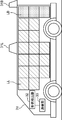
- FIG. 2 is a left side view showing an example of arrangement of the left locker of the unmanned delivery vehicle 2 shown in FIG. 1
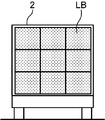
- FIG. 3 is a rear view showing an example of arrangement of the locker on the rear side of the unmanned delivery vehicle 2 shown in FIG.
- FIG. 4 is a right side view showing an arrangement example of the locker on the right side of the unmanned delivery vehicle 2 shown in FIG.
- FIG. 2 on the left side (left side) of the unmanned delivery vehicle 2, there are three lockers LL in the height direction and six lockers LL in the horizontal direction except for a part on the front side, the rear side, and the tire side. Arranged in a grid. Further, as shown in FIG. 3, on the rear side (rear surface) of the unmanned delivery vehicle 2, three lockers LB in the height direction and three lockers LB in the horizontal direction are arranged in a lattice pattern. As shown in FIG. 4, on the right side of the unmanned delivery vehicle 2, three rockers LR in the height direction and six rockers LR in the horizontal direction except for a part on the front side, the rear side and the tire side. Is arranged.
- the direction of the take-out position of the locker LL is on the left side of the unmanned delivery vehicle 2
- the direction of the take-out position of the locker LB is on the rear side of the unmanned delivery vehicle 2
- the take-off position of the locker LR is Is the right side of the unmanned delivery vehicle 2.
- the height of the picking-up position of the lockers LL, LB, and LR is three levels: a high position on the upper stage, an intermediate position on the middle stage, and a low position on the lower stage.
- a locker is arrange
- Various changes are possible.
- FIG. 5 is a left side view showing an example of the arrangement of lockers on the left side of another unmanned delivery vehicle that can be used in the position determination system shown in FIG. 1, and FIG. 6 can be used in the position determination system shown in FIG.
- FIG. 7 is a front view showing an example of the arrangement of lockers on the front side of another unmanned delivery vehicle.
- FIG. 7 is a right side view showing an example of arrangement of lockers on the right side of another unmanned delivery vehicle that can be used in the position determination system shown in FIG. FIG.
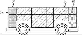
- FIG. 5 on the left side of the unmanned delivery vehicle 2a, three rockers LL in the height direction and seven rockers LL in the horizontal direction are arranged in a lattice pattern except for a part on the front side, rear side, and tire side.
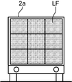
- FIG. 6 on the front side (front surface) of the unmanned delivery vehicle 2a, three lockers LF in the height direction and three in the horizontal direction are arranged in a lattice shape.
- FIG. 7 on the right side of the unmanned delivery vehicle 2a, three rockers LR in the height direction and seven rockers LR in the horizontal direction except for a part on the front side, the rear side and the tire side. Is arranged.
- a locker LB is arranged behind the unmanned delivery vehicle 2a as in FIG.
- the direction of the baggage removal position of the locker LL is the left side of the unmanned delivery vehicle 2a
- the direction of the baggage removal position of the locker LF is the front side of the unmanned delivery vehicle 2a
- the direction of the baggage removal position of the locker LR is on the right side of the unmanned delivery vehicle 2a
- the direction of the take-out position of the locker LB is on the rear side of the unmanned delivery vehicle 2a.
- the height of the pick-up position of the lockers LL, LF, LR, and LB is three stages, that is, a high position on the upper stage, an intermediate position on the middle stage, and a low position on the lower stage.
- the unmanned delivery vehicle 2 a in which the lockers are arranged in this way may be used in the position determination system shown in FIG. 1 instead of the unmanned delivery vehicle 2.
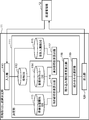
- FIG. 8 is a block diagram showing an example of the configuration of the package removal position determination unit 11 shown in FIG. 8 includes an input unit 110, a determination unit 111, and an output unit 120.
- the determination unit 111 includes a luggage DB (database) 112, a stop position attribute DB (database) 113, a mobile locker DB (database) 114, a recipient attribute DB (database) 115, an orientation appropriateness table calculation unit 116, an appropriate height A degree table calculation unit 117, a loading appropriateness table calculation unit 118, and a combination selection unit 119 are provided.
- Package table data in which the loader P1 uses the loader terminal 3 to associate identification numbers of a plurality of packages to be delivered, delivery addresses, and recipient identification information for identifying recipients.
- the delivery management unit 12 receives the data of the package table from the terminal 3 for the person in charge of loading, and outputs it to the input unit 110.
- the input unit 110 causes the package DB 112 to store the package table data from the delivery management unit 12.
- the package DB 112 outputs the stored package table data to the orientation appropriateness table calculation unit 116 and the height appropriateness table calculation unit 117.
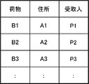
- FIG. 9 is a diagram showing an example of a package table stored in the package DB 112 shown in FIG.
- package table data in which a package (package identification number), an address (delivery address), and a recipient (recipient identification number) are associated with each other is stored in the package DB 112 in a table format. Is done.
- the delivery address of the package “B1” is “A1”
- the recipient of the package “B1” is “P1”.
- the recipient identification information and the like are not particularly limited to the above example, and various modifications such as using the recipient's name and the like can be made.
- the moving body locker DB 114 stores in advance data of a moving body locker table in which the identification number of the locker of the unmanned delivery vehicle 2, the direction of the locker, and the height of the locker are associated with each other.
- the mobile body locker DB 114 outputs the stored mobile body locker table data to the orientation appropriateness table calculation unit 116 and the height appropriateness table calculation unit 117.
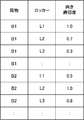
- FIG. 10 is a diagram showing an example of the mobile body locker table stored in the mobile body locker DB 114 shown in FIG.
- data of a mobile rocker table in which a locker (a locker identification number), a locker direction, and a locker height are associated with each other is stored in the mobile rocker DB 114 in a table format.
- the direction of the locker with the identification number “L1” is “left” (the locker disposed on the left side of the unmanned delivery vehicle 2), and the height thereof is “high” (located on the upper stage of the unmanned delivery vehicle 2). Locker).
- the loader P1 uses the loader terminal 3 to use the loader's terminal 3, the address of the delivery destination of the package, the stop position where the unmanned delivery vehicle 2 stops when delivering the package to the address, and the attributes of the stop position.
- the delivery management unit 12 receives the stop position attribute table data from the loading person terminal 3 and outputs the data to the input unit 110.
- the input unit 110 stores the data of the stop position attribute table from the delivery management unit 12 in the stop position attribute DB 113.
- the stop position attribute DB 113 stores in advance stop position attribute information indicating stop position attributes, data of a stop position attribute-direction appropriateness table in which the unloading direction and the appropriateness of direction are associated with each other.
- the stop position attribute DB 113 outputs the stored stop position attribute table data and stop position attribute-direction appropriateness table data to the orientation appropriateness table calculating unit 116.
- the data of the stop position attribute table is not particularly limited to the above example, and may be stored in advance in the stop position attribute DB 113.
- FIG. 11 is a diagram showing an example of a stop position attribute table stored in the stop position attribute DB 113 shown in FIG.
- stop position attribute table data in which addresses (delivery addresses), stop positions, and stop position attributes (stop position attribute information) are associated with each other is stored in the stop position attribute DB 113 in a table format. Is done.
- the stop position of the delivery address “A1” is “x1, y1”, and the stop position attribute information of the stop position is “the amount of traffic is large” (the amount of traffic of the car is greater than the predetermined amount). It is the traffic volume information regarding the traffic volume indicating.
- the stop position of the delivery address “A2” is “x2, y2”, and the stop position attribute information of the stop position is that of the unmanned delivery vehicle 2 indicating “backward stop” (stopping backward). This is stop direction information related to the stop direction.
- the stop position of the delivery address “A3” is “x3, y3”, and the stop position attribute information of this stop position is an obstacle around the stop position indicating that “the obstacle is on the left side”. Obstacle information about.
- the stop position attribute information is not particularly limited to the above example, and various changes are possible. For example, using the lane number information regarding the number of lanes on the road at the stop position, the “number of lanes of two or more lanes on one side” Lane number information indicating, etc., traffic volume information regarding the traffic volume at the stop position, lane number information regarding the number of lanes on the road at the stop position, stop direction information regarding the stop direction of the unmanned delivery vehicle 2, and surroundings of the stop positions At least one of the obstacle information regarding the obstacle may be used.
- FIG. 12 is a diagram showing an example of the stop position attribute-direction appropriateness table stored in the stop position attribute DB 113 shown in FIG.
- the stop position attribute-direction appropriateness table data in which the stop position attribute (stop position attribute information), the unloading direction, and the appropriateness of direction are associated with each other is stored in the stop position attribute DB 113 in a table format.
- the stop position attribute information is traffic information “traffic is heavy”, the appropriateness of orientation “1.0”, “0.7” for the unloading directions “left”, “rear”, “right” ”And“ 0.3 ”are set. Further, when the stop position attribute information is stop direction information “rearward stop”, the appropriateness of orientation “0.5”, “1.0”, “unloading direction” “left”, “rear part”, “right” “0.8” is set. In addition, when the stop position attribute information is the obstacle information “obstacle on the left side”, the appropriateness of orientation “0.0”, “0.8” with respect to the unloading direction “left”, “rear part”, “right” ”And“ 1.0 ”are set.
- the orientation appropriateness is a numerical value within a range of 0 to 1.0, where 1.0 represents the direction in which the package is most easily taken out and 0.0 represents the direction in which the package is most difficult to be taken out.
- the orientation appropriateness is not particularly limited to the above example, and an arbitrary value can be set according to the stop position attribute. For example, values in other numerical ranges can be used, and “appropriate” and “inappropriate” Various changes such as using a level display such as “” are possible.
- the orientation appropriateness table calculation unit 116 retrieves the package for each of the plurality of retrieval position orientations for each package based on the stop position attribute information associated with the delivery address of each of the plurality of packages.
- the orientation appropriateness representing the degree of ease is calculated, and the calculated orientation appropriateness is loaded and output to the appropriateness degree table calculating unit 118.
- FIG. 13 is a diagram showing an example of the address-orientation appropriateness table.
- the address-direction appropriateness table data in which addresses, unloading directions, and appropriateness of direction are associated with each other is displayed in a table format. Created. For example, in the case of the address “A1”, the appropriateness of orientation “1.0”, “0.7”, “0.3” is associated with the unloading directions “left”, “rear”, “right”. ing.
- the orientation appropriateness table calculation unit 116 uses the package table data from the package DB 112, the mobile body locker table data from the mobile locker DB 114, and the created address-direction appropriateness table data. Then, the data of the package orientation appropriateness table in which the package, the locker, and the orientation appropriateness are associated with each other is created, and the created package orientation appropriateness table data is loaded and output to the loading suitability table calculating unit 118.
- FIG. 14 is a diagram showing an example of a package orientation appropriateness table.
- the package orientation appropriate for each package is associated with the package (package identification number), the locker (locker identification number), and the orientation appropriateness.
- Timetable data is created in table format. For example, in the case of the luggage “B1”, the orientation appropriateness “1.0”, “0.7”, “0.3”,... Corresponds to the lockers “L1”, “L2”, “L3”,. It is attached.
- the delivery management unit 12 receives the recipient attribute table data from the loading person terminal 3 and outputs it to the input unit 110.
- the input unit 110 stores the recipient attribute table data from the delivery management unit 12 in the recipient attribute DB 115.
- the recipient attribute DB 115 stores in advance recipient attribute-height appropriateness table data in which the recipient attribute information, the locker height (unloading height), and the height appropriateness are associated with each other. Yes.
- the recipient attribute DB 115 outputs the stored recipient attribute table data and recipient attribute-height appropriateness table data to the height appropriateness table calculating unit 117.
- the recipient attribute table data is not particularly limited to the above example, and may be stored in advance in the recipient attribute DB 115.
- FIG. 15 is a diagram showing an example of a recipient attribute table stored in the recipient attribute DB 115 shown in FIG.
- data of a recipient attribute table in which a recipient (recipient identification information) is associated with a recipient attribute (recipient attribute information) is stored in the recipient attribute DB 115 in a table format.
- the recipient attribute information of the recipient “P1” is height information regarding the height of the recipient indicating “normal” (the height of the recipient is within the normal range).
- the recipient attribute information of the recipient “P2” is age information regarding the age of the recipient indicating “elderly” (the age of the recipient is higher than a predetermined value).
- the recipient attribute information of the recipient “P3” is failure information regarding the presence or absence of the failure of the recipient that indicates “handicapped” (the recipient has a failure). Further, when the recipient's height is lower than a predetermined value, “low” height information is used, and when the recipient's height is higher than a predetermined value, “high” height information is used.
- the recipient attribute information is not particularly limited to the above example and can be variously changed.
- gender information such as gender is used, or height information of the recipient such as “170 cm” is used as the height information.
- the age value of the recipient such as “75 years old” may be used as age information, or other information such as “wheelchair” may be used as failure information.
- the recipient attribute information for example, at least one of height information related to the height of the recipient P2, age information related to the age of the recipient P2, and failure information related to the presence or absence of the failure of the recipient P2 may be used. Good.
- FIG. 16 is a diagram showing an example of a recipient attribute-height appropriateness table stored in the recipient attribute DB 115 shown in FIG. As shown in FIG. 16, the recipient attribute-height appropriateness table data in which the recipient attribute (recipient attribute information), the locker height, and the height appropriateness are associated with each other in the table format. Is remembered.
- the recipient attribute is height information of “normal”, the height appropriateness “1.0”, “0.9”, “0” for the locker height “high”, “medium”, “low”. .8 “is set.
- the recipient attribute is age information of “elderly”, the height appropriateness “0.3”, “1.0”, “ 0.9 “is set.
- the height appropriateness “0.0”, “0.2” with respect to the locker height “high”, “medium”, “low”. “1.0” is set.
- the height appropriateness is a numerical value within the range of 0 to 1.0, where 1.0 represents the height at which the luggage is most easily taken out and 0.0 represents the height at which the luggage is most difficult to be taken out. Yes.
- the height appropriateness is not particularly limited to the above example, and an arbitrary value can be set according to the recipient attribute. For example, values in other numerical ranges can be used, or “appropriate” and “ Various changes such as using a level display such as “unsuitable” are possible.
- the height appropriateness table calculation unit 117 determines the height of a plurality of pick-up positions for each package based on the recipient attribute information associated with the recipient identification information for identifying each recipient of the plurality of packages. The height appropriateness indicating the degree of ease of taking out the package for each of the items is calculated, and the calculated height appropriateness is output to the loading appropriateness table calculating unit 118.
- FIG. 17 is a diagram showing an example of the recipient-height appropriateness table. As shown in FIG. 17, for each combination of all recipients and locker heights, there is data in the recipient-height appropriateness table in which the recipients, locker heights, and height appropriateness are associated with each other. Created in table format. For example, in the case of the recipient “P1”, the height appropriateness “1.0”, “0.9”, “0.8” corresponds to the locker height “high”, “medium”, “low”. It is attached.
- the height appropriateness table calculation unit 117 includes data on the package table from the package DB 112, data on the mobile unit locker table from the mobile unit locker DB 114, and data on the created recipient-height appropriateness table. Is used to create a package height appropriateness table data that correlates packages, lockers, and height appropriateness, and loads the created package height appropriateness table data to load appropriateness table calculation unit It outputs to 118.
- the height appropriateness table calculation unit 117 reads “select luggage, locker, height appropriateness from luggage list, mobile locker table, recipient-height appropriateness table where. Carrying out the process of “Package table.
- Recipient Recipient-Height appropriateness table.
- Locker height Recipient-Height appropriateness table. Locker height" Create a relevance table.
- FIG. 18 is a diagram showing an example of a package height appropriateness table. As shown in FIG. 18, for each combination of all packages and each locker, the package height in which the package (package identification number), the locker (locker identification number), and the height appropriateness are associated with each other.
- the appropriateness table data is created in a table format. For example, in the case of the luggage “B1”, the height appropriateness “1.0”, “0.9”, “0.8”,... Is given to the lockers “L1”, “L2”, “L3”,. It is associated.
- the loading appropriateness table calculation unit 118 and the combination selection unit 119 determine the orientation of each pick-up position of each of the plurality of packages based on the orientation appropriateness of the orientation appropriateness table, and the appropriateness of the height appropriateness table. Based on the degree, the height of the pick-up position of each of the plurality of loads is determined, and the direction of the pick-up position and the height of the determined load are correlated with the direction of the pick-up position of the load. Management information that associates a package with a locker for loading the package is created and output to the output unit 120 as management information that manages the management information and the package and the height at which the package is taken out.
- the output unit 120 outputs management information in which the package is associated with the locker for loading the package to the delivery management unit 12.
- the delivery management unit 12 transmits management information in which a package is associated with a locker for loading the package to the loader terminal 3 when the package is loaded, and to the recipient terminal 4 when the package is received. .
- the loading appropriateness table calculation unit 118 uses the package orientation appropriateness table from the orientation appropriateness table calculation unit 116 and the package height appropriateness table from the height appropriateness table calculation unit 117.
- the loading appropriateness table data in which the luggage, the locker, and the loading appropriateness are associated with each other is created.
- the appropriateness of loading is the appropriateness of taking out indicating the degree of ease of taking out the package for each of a plurality of takeout positions. Therefore, by the above processing, the loading appropriateness table calculating unit 118 takes out the degree of ease of taking out the package for each of a plurality of takeout positions for each package based on the appropriateness of orientation and the appropriateness of height. The appropriateness is calculated, and the direction and height of each takeout position of each of the plurality of loads is determined based on the takeout appropriateness.
- the calculation of the loading appropriateness s (i, j) is not particularly limited to the above example, and the algebraic product “sa (i, j) ⁇ sp (i, j)” and the limit product “max (0, sa) Any product operator can be used, such as (i, j) + sp (i, j) -1).
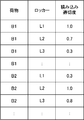
- FIG. 19 is a diagram showing an example of the loading appropriateness table.
- the loading appropriateness table data in which the package, the locker, and the loading appropriateness are associated with each other is created in a table format. For example, in the case of the luggage “B1”, the loading appropriateness “1.0”, “0.7”, “0.3”,... Corresponds to the lockers “L1”, “L2”, “L3”,. It is attached.
- the combination selection unit 119 uses the data of the loading appropriateness table created by the loading appropriateness table calculation unit 118 to calculate ⁇ is (i, j), A combination that maximizes the sum of the “loading appropriateness s (i, j)” of all the packages is obtained, and data of a loading instruction table in which the packages are associated with the lockers for loading the packages is generated and output unit 120 Output to.
- FIG. 20 is a diagram showing an example of the loading instruction table.
- loading instruction table data in which a package (package identification number) is associated with a locker (locker identification number) for loading the package is created in a table format. For example, the load “B1” is loaded into the locker “L1”, the load “B2” is loaded into the locker “L2”, and the load “B3” is loaded into the locker “L8”.
- management information is created in consideration of both stop position attribute information and recipient attribute information.
- the present invention is not particularly limited to this example, and only stop position attribute information is considered.
- the management information may be created, or the management information may be created considering only the recipient attribute information.
- the “orientation appropriateness sa (i, j)” for j may be calculated.
- the “height appropriateness sa (i, j)” may be calculated.
- FIG. 21 is a flowchart illustrating an example of a package removal position determination process by the package removal position determination unit 11 illustrated in FIG.
- the orientation appropriateness table calculation unit 116 creates address-orientation appropriateness table data using the stop position attribute table data and the stop position attribute-direction appropriateness table data from the stop position attribute DB 113, and Using the package table data from the package DB 112, the mobile unit locker table data from the mobile unit locker DB 114, and the created address-orientation table, the package orientation appropriateness table data is calculated. (Step S11).
- the height appropriateness table calculation unit 117 uses the data of the recipient attribute table and the data of the recipient attribute-height appropriateness table from the recipient attribute DB 115, and uses the data of the recipient attribute-height appropriateness table.
- the height of the package is generated using the data of the package table from the package DB 112, the data of the mobile unit locker table from the mobile unit locker DB 114, and the data of the created recipient-height appropriateness table.
- the data of the appropriateness table is calculated (step S12).
- the loading appropriateness table calculating unit 118 uses the luggage orientation appropriateness table from the orientation appropriateness table calculating unit 116 and the package height appropriateness table from the height appropriateness table calculating unit 117.
- the data of the appropriateness table is calculated (step S13).
- the combination selection unit 119 uses the loading appropriateness table created by the loading appropriateness table calculating unit 118 to select a combination that maximizes the loading appropriateness for all combinations that put the package i into the locker j. (Step S14).
- the output unit 120 outputs management information associating the package with the locker for loading the package to the delivery management unit 12 based on the combination of the selected package and the locker (step S15).
- the delivery management unit 12 transmits management information in which the package is associated with the locker for loading the package to the loading person's terminal 3 when loading the package, and the recipient's terminal 4 when receiving the package. Send to.
- FIG. 22 is a diagram showing an example of management information displayed on the terminal 3 for loading persons shown in FIG. 1, and FIG. 23 is an example of management information displayed on the terminal 4 for recipients shown in FIG. FIG.
- the above management information is sent to the loading person's terminal 3 when loading the package, for example, as shown in FIG. 22, please load the “target package: package“ B3 ”” and “locker“ L7 ” (Upper right side) "is displayed, and the loading person P1 loads the load” B3 "into the locker” L7 "of the unmanned delivery vehicle 2.
- the package corresponding to each of the plurality of take-out position directions based on the stop position attribute information associated with each delivery address of the plurality of packages.
- the recipient attribute information associated with the recipient identification information for identifying each recipient of the plurality of packages For each package based on the recipient attribute information associated with the recipient identification information for identifying each recipient of the plurality of packages.
- multiple takeout positions for each package The appropriateness of picking up (the appropriateness of loading) representing the degree of ease of picking up the package for each of the items is calculated, and based on the calculated appropriateness of picking up, the direction and height of each of the plurality of loads are determined.
- the direction of the pick-up position of each piece of baggage can be determined in a direction suitable for the attribute of the stop position, and the height of the pick-up position of each of the plural pieces of baggage can be determined to a height suitable for the attribute of the recipient. be able to.
- the orientation and height of the take-out position are suitable for the attributes of the stop position and the attributes of the recipient P2.
- the direction of the baggage takeout position suitable for the baggage receiving location can be determined, and the height of the baggage takeout position suitable for the recipient can be determined. And the recipient can easily take out the package.
- the configuration of the determination unit 111 is not particularly limited to the above example, and may be as follows. For example, when the stop position attribute information includes the traffic information related to the traffic volume at the stop position, the determination unit 111 corresponds to the traffic information indicating that the address of the delivery destination of the baggage is greater than the predetermined amount. If attached, the direction of the baggage removal position may be determined on the opposite side of the center line of the roadway.
- the determination unit 111 associates the address of the delivery destination of the luggage with the lane number information indicating the number of lanes of two or more lanes on one side. If so, the direction of the baggage removal position may be determined at the outermost side of the vehicle lane.
- the determination unit 111 is associated with stop direction information indicating that the address of the delivery destination of the package stops backward. If there is, the direction of the baggage take-out position may be determined behind the unmanned delivery vehicle 2.
- the determination unit 111 determines that the address of the delivery destination of the package has an obstacle in the vicinity (for example, a gutter on the left side). If the information is associated with obstacle information indicating that there is an obstacle), the direction of the baggage take-out position may be determined as the side without the obstacle.
- the determination unit 111 indicates that the height information indicates that the height of the recipient is lower than a predetermined value (for example, the height is lower than 140 cm).
- the height of the baggage removal position may be determined at a position lower than a predetermined intermediate position (for example, a lower locker).
- the determination unit 111 indicates that the age information of the recipient P2 is higher than a predetermined value (for example, the age is higher than 65 years).
- a predetermined value for example, the age is higher than 65 years.
- the height of the baggage take-out position may be determined to be lower than a predetermined intermediate position (for example, a lower locker).
- the determination unit 111 determines the height of the baggage removal position when the failure information indicates that the recipient P2 has a failure.
- the position may be determined to be lower than the intermediate position (for example, the lower rocker).
- the unmanned delivery vehicle 2 in which a plurality of lockers are fixed is used.
- an unmanned delivery vehicle in which the lockers are movable is used and based on the management information.
- the locker is moved in the unmanned delivery vehicle so that the direction of the baggage removal position becomes a direction suitable for the attribute of the stop position and / or a height suitable for the attribute of the recipient.
- the configuration of the position determination system according to the present embodiment is the same as that of the position determination system shown in FIG. 1 except for an unmanned delivery vehicle, and thus illustration and detailed description thereof are omitted.
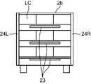
- FIG. 24 is a cross-sectional view of an example of the unmanned delivery vehicle moving mechanism used in the position determination system according to the second embodiment of the present disclosure as viewed from above, and FIG. 25 is the unmanned delivery vehicle moving mechanism shown in FIG. It is sectional drawing which looked at an example from the rear surface.
- An unmanned delivery vehicle 2b shown in FIGS. 24 and 25 includes a communication unit 21, a control unit 22, and a turntable type moving mechanism unit 23, and includes a left extraction port 24L, a right extraction port 24R, or a rear extraction port. It is an autonomous vehicle capable of taking out the luggage from 24B.
- the communication unit 21 is communicably connected to the position determination device 1 (see FIG. 1) via a predetermined wireless network (not shown), receives management information and the like from the position determination device 1 and receives the control unit 22. Output to.
- the control unit 22 uses the communication unit 21 to acquire management information from the position determination device 1 and controls the turntable type moving mechanism unit 23 so that the orientation of the baggage removal position is arranged according to the management information. To do.
- the turntable type moving mechanism unit 23 is a moving mechanism unit for moving the locker LC storing the luggage, and includes an upper turntable, a middle turntable, and a lower turntable.
- the upper turntable, the middle turntable, and the lower turntable are direction changing mechanisms that change the direction of the baggage takeout position to one of the baggage takeout ports 24L, 24R, and 24B.
- the upper turntable moves the locker LC storing the load in the direction of the arrow in the drawing, so that the locker LC storing the load is moved to the left outlet 24L of the unmanned delivery vehicle 2 and the right side. Move to either the takeout port 24R or the rear takeout port 24B. Similarly, in the middle turntable and the lower turntable, the locker LC storing the baggage is placed up to any of the left outlet 24L, the right outlet 24R, or the rear outlet 24B of the unmanned delivery vehicle 2. Move.
- the locker LC of the unmanned delivery vehicle 2b is movable, and the loading position of the baggage may be arbitrary at the time of loading, and according to the management information determined by the position determination device 1 described above by the time of receipt,
- the locker LC that is, the load
- the height at which the luggage is taken out is high according to the management information by the person in charge of loading P1 (see FIG. 1) at the time of loading. Load your luggage into the locker LC.
- the management information is acquired from the position determination device 1, and the locker LC, that is, the luggage is removed from the left outlet 24L so that the orientation of the luggage removal position is arranged according to the management information. , It is moved to either the right outlet 24R or the rear outlet 24B. Therefore, the direction of the take-out position can be automatically arranged in a direction suitable for the attribute of the stop position, and when delivering the package using the unmanned delivery vehicle 2b, the package take-out position suitable for the package receiving location. The recipient can easily take out the package from the direction (left take-out port 24L, right take-out port 24R, or rear take-out port 24B).
- the moving mechanism unit is not particularly limited to the above-described turntable type moving mechanism unit 23, and various modifications are possible.
- a moving mechanism unit that can move a locker, that is, a load in the horizontal direction and the vertical direction is used. May be.
- FIG. 26 is a cross-sectional view of an example of a moving mechanism of another unmanned delivery vehicle used in the position determination system according to the second embodiment of the present disclosure
- FIG. 27 is a cross-sectional view of the unmanned delivery vehicle shown in FIG. It is sectional drawing which looked at an example of the moving mechanism from the rear surface.
- An unmanned delivery vehicle 2c shown in FIGS. 26 and 27 includes a communication unit 21, a control unit 22, and a crane type moving mechanism unit 25 having a fork 25a, and has a left outlet 24L, a right outlet 24R, or a rear side.
- This is an autonomous vehicle capable of taking out the luggage stored in the upper, middle, or lower lockers from the side take-out port 24B.
- the communication unit 21 is communicably connected to the position determination device 1 via a predetermined wireless network (not shown), receives management information from the position determination device 1 and outputs it to the control unit 22.
- the control unit 22 uses the communication unit 21 to acquire management information from the position determining device 1, and the crane type moving mechanism unit 25 so that the direction and height of the baggage removal position are arranged according to the management information. To control.
- the crane-type moving mechanism unit 25 is a moving mechanism unit that moves the locker LC that stores the load, and is a direction and height changing mechanism that changes the direction and height of the load removal position. Specifically, the crane type moving mechanism unit 25 inserts the fork 25a into the lower part of the locker LC and moves the locker LC in the horizontal direction and the vertical direction (in the direction of the arrow in the drawing), thereby Is changed to one of the baggage take-out ports 24L, 24R, and 24B, and the height of the baggage take-out position is changed to any one of the upper, middle, and lower levels.
- An example of the operation will be specifically described.
- the loading person P1 loads the luggage i into the vacant locker j.
- the person in charge of loading P1 inputs the fact that the package i has been loaded into the locker j to the terminal 3 for persons in charge of loading (see FIG. 1) and notifies the delivery management unit 12 (see FIG. 1).
- a non-contact IC tag IC tag
- FIG. 1 IC tag
- the delivery management unit 12 sets management information instructing to move the locker j to the direction and height of the determined position for taking out the package i. It transmits to the communication part 21 of the unmanned delivery vehicle 2c.
- control unit 22 of the unmanned delivery vehicle 2c controls the crane type moving mechanism unit 25 according to the management information from the communication unit 21, and the crane type moving mechanism unit 25 determines the locker j containing the luggage i. It moves to the direction and height of the taken-out position of the packaged i.
- the communication unit 21 of the unmanned delivery vehicle 2c confirms that the package i has arrived at the recipient terminal 4 (see FIG. 1) of the recipient P2, and the direction and height of the determined take-out position of the package i.
- the recipient terminal 4 displays that the package i has arrived and the direction and height of the position where the package i is taken out.
- the recipient P2 takes out the package i in accordance with the display on the recipient terminal 4.
- an image photographing device such as a camera is mounted on the unmanned delivery vehicle 2c, and the direction and / or height of the determined take-out position is changed according to the surrounding conditions such as obstacles such as other parked vehicles. Is also possible.
- the locker LC of the unmanned delivery vehicle 2c shown in FIG. 26 and FIG. 27 is movable, and the loading position of the luggage may be arbitrary at the time of loading.
- the locker LC that is, the baggage is moved to one of the baggage outlets 24L, 24R, and 24B, the direction of the baggage takeout position is changed, and the locker LC is moved to any one of the upper, middle, and lower levels That is, the package is moved and the height of the package removal position is changed. It is desirable to complete the movement of the parcel by the time of receipt.
- the unmanned delivery vehicle 2c shown in FIGS. 26 and 27 acquires the management information from the position determination device 1, and the locker is arranged so that the direction and height of the baggage removal position are arranged according to the management information.
- the LC is moved to any of the left outlet 24L, the right outlet 24R, or the rear outlet 24B, and is moved to any one of the upper, middle, and lower stages. Accordingly, the direction and height of the take-out position can be automatically arranged in the direction suitable for the attribute of the stop position and the height suitable for the attribute of the recipient, and the package is delivered using the unmanned delivery vehicle 2c.
- the recipient can select the package suitable for his / her characteristics from the direction of the package removal position suitable for the package receiving location (left outlet 24L, right outlet 24R, or rear outlet 24B).
- the luggage can be easily taken out at the height of the take-out position (upper, middle, or lower).
- an unmanned delivery vehicle equipped with a range sensor is used, and the orientation appropriateness and the height appropriateness are dynamically changed during operation of the unmanned delivery vehicle.
- the configuration of the position determination system according to the present embodiment is the same as that of the position determination system shown in FIG. 1 except for the unmanned delivery vehicle. Only the details will be described.
- FIG. 28 is a left side view illustrating an example of the configuration of the unmanned delivery vehicle used in the position determination system according to the third embodiment of the present disclosure
- FIG. 29 illustrates the range of the rear side of the unmanned delivery vehicle illustrated in FIG.
- FIG. 30 is a rear view showing an arrangement example of sensors
- FIG. 30 is a right side view showing an arrangement example of range sensors on the right side of the unmanned delivery vehicle shown in FIG.
- An unmanned delivery vehicle 2d shown in FIGS. 28 to 30 includes a left range sensor 31L, a rear range sensor 31B, a right range sensor 31R, a shape detection unit 32, and a communication unit 33. Since this is the same as the unmanned delivery vehicle 2 of the first embodiment, different points will be described below.
- the left range sensor 31L is installed at the upper center of the left side surface of the unmanned delivery vehicle 2d in which a plurality of lockers LL are arranged.
- the rear range sensor 31B is installed at the upper center of the rear surface of the unmanned delivery vehicle 2d in which a plurality of lockers LB are arranged.
- the right ranging sensor 31R is installed at the upper center of the right side surface of the unmanned delivery vehicle 2d in which a plurality of lockers LR are arranged.
- the left range sensor 31L, the rear range sensor 31B, and the right range sensor 31R are scanning type lightwave rangefinders that measure physical shape data of the space around the unmanned delivery vehicle 2d.
- it is composed of a laser scanner or the like.
- the left range sensor 31L acquires the physical shape data of the left space around the unmanned delivery vehicle 2d and outputs it to the shape detection unit 32.
- the rear range sensor 31B acquires physical shape data of the rear space around the unmanned delivery vehicle 2d and outputs it to the shape detection unit 32.
- the right ranging sensor 31R acquires the physical shape data of the right space around the unmanned delivery vehicle 2d and outputs it to the shape detection unit 32.
- the shape detection unit 32 is an unattended delivery that can be an obstacle when taking out the luggage from the locker based on the shape data acquired from the left range sensor 31L, the rear range sensor 31B, and the right range sensor 31R.
- a large convex or concave portion (convex portion or concave portion) of a predetermined value or more on the left, right and rear road surfaces of the vehicle 2d is detected, and concave and convex portion data indicating the detected concave and convex portion is output to the communication unit 33.
- the uneven portion data includes information indicating the address of the delivery destination and direction information on the left side, the right side, or the rear side.
- the shape detection unit 32 detects a guard rail or the like as a convex portion, or detects a side groove or the like as a concave portion.
- the shape data and the concavo-convex portion data need only be data that indicates that there are large convex and concave portions on the left side, the right side, or the rear side, and need not be data that can be recognized.
- the communication unit 33 is communicably connected to the position determination device 1 (see FIG. 1) via a predetermined wireless network (not shown), and the left and right side and rear side unevenness data is transferred to the position determination device 1. Send.
- the delivery management unit 12 of the position determination device 1 receives the uneven portion data from the unmanned delivery vehicle 2d and outputs it to the input unit 110.
- the input unit 110 stores the irregularity data from the unmanned delivery vehicle 2d in the stop position attribute table of the stop position attribute DB 113 in association with the address (delivery destination address).
- the orientation appropriateness table calculation unit 116 calculates the orientation appropriateness with reference to the stop position attribute table in the stop position attribute DB 113 and the like, when the unevenness data is stored in association with the address of the delivery destination, the unevenness data The orientation appropriateness of the unloading direction that matches the detected direction is lowered to a predetermined value, for example, “0.0”, and the orientation appropriateness of the address-orientation appropriateness table shown in FIG. 13 is changed.
- the orientation appropriateness table calculation unit 116 is large. It is possible to determine that the locker arranged in a direction with unevenness is inappropriate for receiving, and to reduce the orientation appropriateness of the direction in which the unevenness data is detected.
- the shape detection unit 32 uses the shape data acquired from the left range sensor 31L, the rear range sensor 31B, and the right range sensor 31R when the recipient takes out the luggage from the locker. Recipient height data is detected, and recipient height data (including recipient identification information) indicating the detected recipient height is output to the communication unit 33.
- the communication unit 33 transmits the receiver height data to the position determination device 1.
- the height of the recipient is not the height of the recipient but the apparent height because the recipient may ride on a wheelchair or the waist of the recipient may be bent.
- the shape detector 32 detects the height to the head of the recipient who is sitting in the wheelchair when the recipient is in a wheelchair, or the waist is bent when the recipient is an elderly person. Or detecting the height up to the recipient's head that is tilted forward.
- the shape data and the recipient height data need only be data that can detect the recipient's height, and need not be data that can recognize the state of the recipient.
- the delivery management unit 12 of the position determination device 1 receives the recipient height data from the unmanned delivery vehicle 2d and outputs it to the input unit 110.
- the input unit 110 stores the recipient height data from the unmanned delivery vehicle 2d in the recipient attribute table of the recipient attribute DB 115 in association with the recipient (recipient identification information).
- the height appropriateness table calculation unit 117 calculates the height appropriateness with reference to the recipient attribute table in the recipient attribute DB 115 and the like, when the recipient height data is stored in association with each other, the recipient The height indicated by the height data, that is, the height appropriateness of the locker higher than the height of the payee is lowered to a predetermined value, for example, “0.0”, and the height appropriate in the payee-height appropriateness table shown in FIG. Change the degree.
- the height appropriateness table calculation unit 117 may determine that a locker that is higher than the height of the recipient is inappropriate for receiving, and can reduce the height appropriateness of the locker height that is higher than the height of the recipient.
- the appropriateness of orientation can be dynamically changed during operation, so that the recipient can easily take out the package from the locker with the orientation suitable for reception.
- the height appropriateness can be dynamically changed during operation, the recipient can easily take out the package from the locker having a height suitable for receiving.
- the left range sensor 31L and the like are added to the unmanned delivery vehicle 2 of the first embodiment, but the present invention is not particularly limited to this example.
- the left range sensor 31L, the rear range sensor 31B, the right range sensor 31R, and the like may be added to the unmanned delivery vehicles 2b and 2c of the second embodiment.
- the left side range sensor 31L, the rear range sensor 31B, and the right range sensor 31R can take the luggage to the takeout port located in a direction other than the direction where the large unevenness is detected.
- the recipient can easily take out the package from the take-out port suitable for receiving the package.
- the unmanned delivery vehicle 2c the recipient is moved to a height lower than the height of the recipient detected by the left range sensor 31L, the rear range sensor 31B, and the right range sensor 31R. The recipient can easily take out the package from a height suitable for the height.
- an unmanned delivery vehicle having a switch operated by a recipient is used, and the appropriateness of orientation and the appropriateness of height are dynamically changed during operation of the unmanned delivery vehicle.
- the configuration of the position determination system according to the present embodiment is the same as that of the position determination system shown in FIG. 1 except for the unmanned delivery vehicle. Only the details will be described.
- FIG. 31 is a left side view illustrating an example of the configuration of an unmanned delivery vehicle used in the position determination system according to the fourth embodiment of the present disclosure
- FIG. 32 illustrates a switch on the rear side of the unmanned delivery vehicle illustrated in FIG.
- FIG. 33 is a rear view showing an arrangement example
- FIG. 33 is a right side view showing an arrangement example of switches on the right side of the unmanned delivery vehicle shown in FIG.
- the unmanned delivery vehicle 2e includes three switches 34LH, 34LM, 34LL on the left side, three switches 34BH, 34BM, 34BL on the rear side, and three switches 34RH, 34RM, 34RL on the right side. Since the switch detection unit 35 and the communication unit 33 are provided and the other configurations are the same as those of the unmanned delivery vehicle 2 of the first embodiment, different points will be described below.
- Switches 34LH, 34LM, and 34LL are installed on the upper, middle, and lower sides of the left side of the unmanned delivery vehicle 2e in which a plurality of lockers LL are arranged (the side of the rear locker LB).
- the switches 34BH, 34BM, and 34BL are installed in the upper, middle, and lower stages of the central portion of the rear surface of the unmanned delivery vehicle 2e in which a plurality of lockers LB are arranged.
- the switches 34RH, 34RM, and 34RL are installed on the upper, middle, and lower sides of the right side of the unmanned delivery vehicle 2e in which a plurality of lockers LR are arranged (the side of the rear locker LB).
- switches 34LH to 34RL are arranged at the upper, middle, and lower positions on the left side, right side, and rear side of the unmanned delivery vehicle 2e. You can press the switch that specifies the locker.
- the number and arrangement of switches are not particularly limited to the above example, and various changes can be made as long as a locker that can be easily received by the recipient can be selected.
- the recipient receives the package from the nine switches 34LH to 34RL if the locker at the receiving position is difficult to receive. Press the switch that specifies the most easily received orientation and height rocker.
- the switch 34LM transmits switch-on data indicating that the recipient has selected the switch 34LM to the switch detection unit 35.
- the switch detection unit 35 receives the switch-on data from the switch 34LM, the switch detection unit 35 outputs to the communication unit 33 switch data indicating that the recipient has selected the left middle locker.
- switch detection unit 35 outputs switch data indicating the direction and height of the locker selected by the recipient to the communication unit 33.
- the communication unit 33 is communicably connected to the position determination device 1 (see FIG. 1) via a predetermined wireless network (not shown), and receives switch data indicating the direction and height of the locker selected by the recipient. It transmits to the position determination apparatus 1.
- the switch data includes information indicating the address of the delivery destination, recipient identification information, direction data indicating the direction of the locker selected by the recipient, and height data indicating the height of the locker selected by the recipient. Including.
- the delivery management unit 12 of the position determination device 1 receives the switch data from the unmanned delivery vehicle 2e and outputs it to the input unit 110.
- the input unit 110 stores the direction data in the switch data from the unmanned delivery vehicle 2e in the stop position attribute table of the stop position attribute DB 113 in association with the address (delivery destination address).
- the orientation appropriateness table calculating unit 116 calculates the orientation appropriateness with reference to the stop position attribute table in the stop position attribute DB 113 and the like
- the orientation data is stored when the orientation data is stored in association with the address of the delivery destination. Is increased to a predetermined value, for example, “1.0”, and the orientation appropriateness in the address-orientation appropriateness table shown in FIG. 13 is changed.
- the method for changing the orientation appropriateness is not particularly limited to the above example.
- the maximum value may be set to “1.0”, and the orientation appropriateness before the change may be increased at a predetermined rate.
- the orientation appropriateness table calculation unit 116 preferentially selects the orientation of the locker that can be easily received by the recipient. , Can increase the appropriateness of orientation.
- the input unit 110 stores the height data among the switch data from the unmanned delivery vehicle 2e in association with the recipient (recipient identification information) in the recipient attribute table of the recipient attribute DB 115.
- the height appropriateness table calculating unit 117 calculates the height appropriateness with reference to the recipient attribute table of the recipient attribute DB 115 and the like, when the height data is stored in association with each other, the height data is stored.
- the height appropriateness of the locker height corresponding to the indicated height is raised to a predetermined value, for example, “1.0”, and the height appropriateness of the recipient-height appropriateness table shown in FIG. 17 is changed.
- the method for changing the appropriateness of height is not particularly limited to the above example. For example, the maximum value may be set to “1.0”, and the height appropriateness before the change may be increased at a predetermined rate.
- the unmanned delivery vehicle 2e receives the above-mentioned switch operation of the recipient at the delivery destination, it is possible to obtain information on the height of the locker that is easily received by the recipient. Thereafter, when the unmanned delivery vehicle 2e or another unmanned delivery vehicle delivers the package to the same recipient, the height appropriateness table calculation unit 117 preferentially selects the height of the locker that is easily received by the recipient. Thus, the height appropriateness can be raised.
- the appropriateness of orientation can be dynamically changed during operation, so that the recipient can easily take out the package from the locker with the orientation suitable for reception.
- the height appropriateness can be dynamically changed during operation, the recipient can easily take out the package from the locker having a height suitable for receiving.
- the switch 34LH and the like are added to the unmanned delivery vehicle 2 of the first embodiment, but the present invention is not particularly limited to this example.
- left switches 34LH, 34LM, 34LL, rear switches 34BH, 34BM, 34BL, and right switches 34RH, 34RM, 34RL may be added to the unmanned delivery vehicles 2b, 2c of the second embodiment.
- the unmanned delivery vehicles 2b and 2c when the unmanned delivery vehicles 2b and 2c receive the above-described switch operation of the recipient at the delivery destination, information on the direction and height of the locker that is easy for the recipient to receive can be obtained. Therefore, in the unmanned delivery vehicle 2b, the recipient can easily take out the package from the take-out port in the direction suitable for receiving the package by moving the package to the take-out port positioned in a direction that is easy for the recipient to receive. In addition, in the unmanned delivery vehicle 2c, by moving the package from the take-out port positioned in the direction easy for the recipient to receive to a height that is easy for the recipient to receive, the unmanned delivery vehicle 2c is suitable for receiving the baggage from the take-out port suitable for receiving the package. The recipient can easily take out the package at a high height.
- the position determination device and the like according to the present disclosure can determine the direction of the baggage take-out position suitable for the baggage receiving location when the baggage is delivered using an unmanned autonomous vehicle. Since it can be easily taken out, it is useful as a position determination device or the like for determining a baggage takeout position of an autonomous vehicle capable of taking out a load from a plurality of takeout positions.
Abstract
Description
上記の特許文献1に記載された自律走行車には、荷物を収納する複数のロッカー(区画)が格子状に配置され、上段、中段、及び下段の各高さ位置に複数のロッカーが水平方向に配置されている。このように、ロッカーの高さ位置が異なる場合、身長の低い受取人や車いすを使用する障害者は、上段のロッカーに収納されている荷物を取り出しにくい。 (Knowledge that became the basis of this disclosure)
In the autonomous vehicle described in Patent Document 1, a plurality of lockers (sections) for storing luggage are arranged in a lattice shape, and a plurality of lockers are horizontally disposed at each of the upper, middle, and lower height positions. Is arranged. Thus, when the height positions of the lockers are different, it is difficult for a recipient with a short height or a disabled person using a wheelchair to take out the luggage stored in the upper locker.
図1は、本開示の実施の形態1における位置決定システムの構成の一例を示す概略図である。図1に示す位置決定システムは、位置決定装置1、無人配達車2、積み込み担当者用端末3、及び受取人用端末4を備える。位置決定装置1は、荷物取り出し位置決定部11、及び配達管理部12を備える。 (Embodiment 1)
FIG. 1 is a schematic diagram illustrating an example of a configuration of a position determination system according to the first embodiment of the present disclosure. The position determination system shown in FIG. 1 includes a position determination device 1, an
上記の実施の形態では、複数のロッカーが固定されている無人配達車2を用いたが、本実施の形態では、ロッカーが可動式になっている無人配達車を用い、上記の管理情報に基づき、荷物の取り出し位置の向きを停車位置の属性に適した向き及び/又は受取人の属性に適した高さとなるように、ロッカーを無人配達車内で移動させる。なお、本実施の形態の位置決定システムの構成は、無人配達車を除き、図1に示す位置決定システムと同様であるので、図示及び詳細な説明を省略する。 (Embodiment 2)
In the above embodiment, the
本実施の形態では、測域センサを備える無人配達車を用い、向き適切度及び高さ適切度を無人配達車の運用時に動的に変化させる。なお、本実施の形態の位置決定システムの構成は、無人配達車を除き、図1に示す位置決定システムと同様であるので、図示及び詳細な説明を省略し、実施の形態1と異なる点についてのみ詳細に説明する。 (Embodiment 3)
In the present embodiment, an unmanned delivery vehicle equipped with a range sensor is used, and the orientation appropriateness and the height appropriateness are dynamically changed during operation of the unmanned delivery vehicle. The configuration of the position determination system according to the present embodiment is the same as that of the position determination system shown in FIG. 1 except for the unmanned delivery vehicle. Only the details will be described.
本実施の形態では、受取人が操作するスイッチを備える無人配達車を用い、向き適切度及び高さ適切度を無人配達車の運用時に動的に変化させる。なお、本実施の形態の位置決定システムの構成は、無人配達車を除き、図1に示す位置決定システムと同様であるので、図示及び詳細な説明を省略し、実施の形態1と異なる点についてのみ詳細に説明する。 (Embodiment 4)
In this embodiment, an unmanned delivery vehicle having a switch operated by a recipient is used, and the appropriateness of orientation and the appropriateness of height are dynamically changed during operation of the unmanned delivery vehicle. The configuration of the position determination system according to the present embodiment is the same as that of the position determination system shown in FIG. 1 except for the unmanned delivery vehicle. Only the details will be described.
2,2a~2e 無人配達車
3 積み込み担当者用端末
4 受取人用端末
11 荷物取り出し位置決定部
12 配達管理部
110 入力部
111 決定部
112 荷物DB
113 停車位置属性DB
114 移動体ロッカーDB
115 受取人属性DB
116 向き適切度表算出部
117 高さ適切度表算出部
118 積み込み適切度表算出部
119 組み合わせ選択部
120 出力部 DESCRIPTION OF SYMBOLS 1
113 Stop position attribute DB
114 Mobile locker DB
115 Recipient attribute DB
116 Orientation appropriateness
Claims (19)
- 複数の取り出し位置から荷物の取り出しが可能な自律走行車の荷物の取り出し位置を決定する位置決定装置であって、
前記荷物の配達先の住所と、当該住所に荷物を配達するときに前記自律走行車が停止する停車位置の属性を示す停車位置属性情報とを取得する取得部と、
前記荷物の配達先の住所に対応付けられている前記停車位置属性情報を基に、前記荷物の前記取り出し位置の向きを決定する決定部と、
前記荷物と当該荷物の前記取り出し位置の向きとを対応付けて管理する管理情報を出力する出力部とを備える、
位置決定装置。 A position determination device for determining a position for picking up a baggage of an autonomous vehicle capable of picking up a baggage from a plurality of pick-up positions,
An acquisition unit that acquires an address of a delivery destination of the package and stop position attribute information indicating an attribute of a stop position at which the autonomous vehicle stops when delivering the package to the address;
A determination unit that determines an orientation of the take-out position of the package based on the stop position attribute information associated with the address of the delivery destination of the package;
An output unit that outputs management information for managing the package and the direction of the take-out position of the package in association with each other;
Positioning device. - 前記停車位置属性情報は、前記停車位置の交通量に関する交通量情報、前記停車位置の道路の車線数に関する車線数情報、前記自律走行車の停車向きに関する停車向き情報、及び前記停車位置の周囲の障害物に関する障害物情報のうち少なくとも一つを含む、
請求項1記載の位置決定装置。 The stop position attribute information includes traffic information relating to the traffic volume at the stop position, lane number information relating to the number of lanes of the road at the stop position, stop direction information relating to the stop direction of the autonomous vehicle, and surroundings of the stop positions. Contains at least one obstacle information about obstacles,
The position determining apparatus according to claim 1. - 前記停車位置属性情報は、前記停車位置の交通量に関する交通量情報を含み、
前記決定部は、前記荷物の配達先の住所が、所定量より車の交通量が多いことを示す前記交通量情報と対応付けられている場合、前記荷物の前記取り出し位置の向きを車道の中央線と反対側に決定する、
請求項1記載の位置決定装置。 The stop position attribute information includes traffic information related to the traffic volume of the stop position,
When the address of the delivery destination of the package is associated with the traffic information indicating that the traffic volume of the vehicle is greater than a predetermined amount, the determination unit sets the direction of the take-out position of the package to the center of the roadway Decide on the opposite side of the line,
The position determining apparatus according to claim 1. - 前記停車位置属性情報は、前記停車位置の道路の車線数に関する車線数情報を含み、
前記決定部は、前記荷物の配達先の住所が、片側2車線以上の車線数を示す前記車線数情報と対応付けられている場合、前記荷物の前記取り出し位置の向きを車両通行帯の最も外側に決定する、
請求項1に記載の位置決定装置。 The stop position attribute information includes lane number information regarding the number of lanes of the road at the stop position,
In the case where the delivery address of the package is associated with the lane number information indicating the number of lanes of two or more lanes on one side, the determination unit determines the direction of the take-out position of the package on the outermost side of the vehicle lane To decide,
The position determining device according to claim 1. - 前記停車位置属性情報は、前記自律走行車の停車向きに関する停車向き情報を含み、
前記決定部は、前記荷物の配達先の住所が、後ろ向きに停車することを示す前記停車向き情報と対応付けられている場合、前記荷物の前記取り出し位置の向きを前記自律走行車の後ろ側に決定する、
請求項1に記載の位置決定装置。 The stop position attribute information includes stop direction information related to the stop direction of the autonomous vehicle,
When the address of the delivery destination of the package is associated with the stop direction information indicating that the package stops backward, the determination unit sets the direction of the pickup position of the package to the rear side of the autonomous vehicle. decide,
The position determining device according to claim 1. - 前記停車位置属性情報は、前記停車位置の周囲の障害物に関する障害物情報を含み、
前記決定部は、前記荷物の配達先の住所が、周囲に障害物があることを示す前記障害物情報と対応付けられている場合、前記荷物の前記取り出し位置の向きを前記障害物のない側に決定する、
請求項1に記載の位置決定装置。 The stop position attribute information includes obstacle information related to obstacles around the stop position,
When the address of the delivery destination of the package is associated with the obstacle information indicating that there is an obstacle in the vicinity, the determination unit sets the direction of the take-out position of the package to the side without the obstacle To decide,
The position determining device according to claim 1. - 前記取得部は、複数の荷物の各々の配達先の住所と、当該住所に荷物を配達するときに前記自律走行車が停止する停車位置の属性を示す前記停車位置属性情報とを取得し、
前記決定部は、前記複数の荷物の各々の配達先の住所に対応付けられている前記停車位置属性情報を基に、前記荷物毎に、前記複数の取り出し位置の向きの各々に対する当該荷物の取り出し易さの程度を表す向き適切度を算出し、前記向き適切度を基に、前記複数の荷物の各々の前記取り出し位置の向きを決定する、
請求項1~6のいずれか1項に記載の位置決定装置。 The acquisition unit acquires an address of each delivery destination of a plurality of packages, and the stop position attribute information indicating an attribute of a stop position where the autonomous vehicle stops when delivering the package to the address,
The determining unit is configured to take out the package for each of the plurality of take-out positions for each of the packages based on the stop position attribute information associated with the delivery address of each of the plurality of packages. Calculating the appropriateness of orientation representing the degree of ease, and determining the orientation of the take-out position of each of the plurality of packages based on the appropriateness of orientation;
The position determining device according to any one of claims 1 to 6. - 前記取得部は、前記荷物の受取人を識別する受取人識別情報と、当該受取人の属性を示す受取人属性情報とを取得し、
前記決定部は、前記受取人識別情報に対応付けられている前記受取人属性情報を基に、前記荷物の前記取り出し位置の高さを決定し、
前記出力部は、前記荷物と当該荷物の前記取り出し位置の高さとを対応付けて管理する管理情報を出力する、
請求項1~7のいずれか1項に記載の位置決定装置。 The acquisition unit acquires recipient identification information for identifying a recipient of the package, and recipient attribute information indicating an attribute of the recipient,
The determination unit determines the height of the take-out position of the package based on the recipient attribute information associated with the recipient identification information,
The output unit outputs management information for managing the baggage and the height of the pick-up position of the baggage in association with each other;
The position determining device according to any one of claims 1 to 7. - 前記受取人属性情報は、前記受取人の身長に関する身長情報、前記受取人の年齢に関する年齢情報、及び前記受取人の障害の有無に関する障害情報のうち少なくとも一つを含む、
請求項8記載の位置決定装置。 The recipient attribute information includes at least one of height information relating to the height of the recipient, age information relating to the age of the recipient, and disability information relating to the presence or absence of the disability of the recipient.
The position determining apparatus according to claim 8. - 前記受取人属性情報は、前記受取人の身長に関する身長情報を含み、
前記決定部は、前記身長情報が、前記受取人の身長が所定値より低いことを示す場合、前記荷物の前記取り出し位置の高さを所定の中間位置より低い位置に決定する、
請求項8記載の位置決定装置。 The recipient attribute information includes height information regarding the recipient's height,
The determination unit determines that the height of the pick-up position of the package is lower than a predetermined intermediate position when the height information indicates that the height of the recipient is lower than a predetermined value;
The position determining apparatus according to claim 8. - 前記受取人属性情報は、前記受取人の年齢に関する年齢情報を含み、
前記決定部は、前記年齢情報が、前記受取人の年齢が所定値より高いことを示す場合、前記荷物の前記取り出し位置の高さを所定の中間位置より低い位置に決定する、
請求項8に記載の位置決定装置。 The recipient attribute information includes age information regarding the age of the recipient,
The determining unit determines that the height of the pick-up position of the package is lower than a predetermined intermediate position when the age information indicates that the age of the recipient is higher than a predetermined value;
The position determining apparatus according to claim 8. - 前記受取人属性情報は、前記受取人の障害の有無に関する障害情報を含み、
前記決定部は、前記障害情報が、前記受取人に障害があることを示す場合、前記荷物の前記取り出し位置の高さを所定の中間位置より低い位置に決定する、
請求項8記載の位置決定装置。 The recipient attribute information includes failure information regarding the presence or absence of the recipient's failure,
When the failure information indicates that the recipient has a failure, the determination unit determines a height of the take-out position of the package to be lower than a predetermined intermediate position.
The position determining apparatus according to claim 8. - 前記取得部は、複数の荷物の各々の受取人を識別する受取人識別情報と、当該受取人の属性を示す前記受取人属性情報とを取得し、
前記決定部は、前記複数の荷物の各々の受取人を識別する前記受取人識別情報に対応付けられている前記受取人属性情報を基に、前記荷物毎に、前記複数の取り出し位置の高さの各々に対する当該荷物の取り出し易さの程度を表す高さ適切度を算出し、前記高さ適切度を基に、前記複数の荷物の各々の前記取り出し位置の高さを決定する、
請求項8~12のいずれか1項に記載の位置決定装置。 The acquisition unit acquires recipient identification information for identifying each recipient of a plurality of packages, and the recipient attribute information indicating an attribute of the recipient,
The determination unit determines the height of the plurality of pick-up positions for each package based on the recipient attribute information associated with the recipient identification information for identifying each recipient of the plurality of packages. Calculating an appropriate height representing the degree of ease of taking out the package for each of the items, and determining the height of the take-out position of each of the plurality of packages based on the appropriate height.
The position determining device according to any one of claims 8 to 12. - 前記取得部は、複数の荷物の各々の配達先の住所と、当該住所に荷物を配達するときに前記自律走行車が停止する停車位置の属性を示す前記停車位置属性情報とを取得するとともに、前記複数の荷物の各々の受取人を識別する受取人識別情報と、当該受取人の属性を示す受取人属性情報とを取得し、
前記決定部は、前記複数の荷物の各々の配達先の住所に対応付けられている前記停車位置属性情報を基に、前記荷物毎に、前記複数の取り出し位置の向きの各々に対する当該荷物の取り出し易さの程度を表す向き適切度を算出し、前記複数の荷物の各々の受取人を識別する前記受取人識別情報に対応付けられている前記受取人属性情報を基に、前記荷物毎に、前記複数の取り出し位置の高さの各々に対する当該荷物の取り出し易さの程度を表す高さ適切度を算出し、前記向き適切度及び高さ適切度を基に、前記荷物毎に、前記複数の取り出し位置の各々に対する当該荷物の取り出し易さの程度を表す取り出し適切度を算出し、前記取り出し適切度を基に、前記複数の荷物の各々の前記取り出し位置の向き及び高さを決定する、
請求項8~12のいずれか1項に記載の位置決定装置。 The acquisition unit acquires an address of each delivery destination of a plurality of luggage and the stop position attribute information indicating an attribute of a stop position at which the autonomous vehicle stops when delivering the luggage to the address, Obtaining recipient identification information for identifying each recipient of the plurality of packages, and recipient attribute information indicating attributes of the recipient;
The determining unit is configured to take out the package for each of the plurality of take-out positions for each of the packages based on the stop position attribute information associated with the delivery address of each of the plurality of packages. Based on the recipient attribute information associated with the recipient identification information that identifies the recipient of each of the plurality of packages, the orientation appropriateness representing the degree of ease is calculated for each package. A height appropriateness representing the degree of ease of taking out the load with respect to each of the heights of the plurality of takeout positions is calculated, and based on the orientation appropriateness and the height appropriateness, Calculating the appropriateness of taking out the degree of ease of taking out the package with respect to each takeout position, and determining the direction and height of the takeout position of each of the plurality of loads based on the appropriateness of taking out,
The position determining device according to any one of claims 8 to 12. - 複数の取り出し位置から荷物の取り出しが可能な自律走行車であって、
前記荷物を移動させる移動機構部と、
請求項1~14のいずれか1項に記載の位置決定装置から前記管理情報を取得し、前記荷物の前記取り出し位置の向きが前記管理情報に応じて配置されるように、前記移動機構部を制御する制御部とを備える、
自律走行車。 An autonomous vehicle that can take out luggage from multiple take-out positions,
A moving mechanism for moving the load;
The management mechanism is acquired from the position determination device according to any one of claims 1 to 14, and the moving mechanism unit is arranged so that an orientation of the take-out position of the package is arranged according to the management information. A control unit for controlling,
Autonomous vehicle. - 前記移動機構部は、前記荷物の前記取り出し位置の向きを変更する向き変更機構を含む、
請求項15記載の自律走行車。 The moving mechanism unit includes an orientation changing mechanism that changes the orientation of the take-out position of the luggage.
The autonomous vehicle according to claim 15. - 前記移動機構部は、前記荷物の前記取り出し位置の高さを変更する高さ変更機構を含む、
請求項15又は16記載の自律走行車。 The moving mechanism unit includes a height changing mechanism that changes the height of the take-out position of the luggage.
The autonomous vehicle according to claim 15 or 16. - 複数の取り出し位置から荷物の取り出しが可能な自律走行車の荷物の取り出し位置を決定する位置決定方法であって、
前記荷物の配達先の住所と、当該住所に荷物を配達するときに前記自律走行車が停止する停車位置の属性を示す停車位置属性情報とを取得し、
前記荷物の配達先の住所に対応付けられている前記停車位置属性情報を基に、前記荷物の前記取り出し位置の向きを決定し、
前記荷物と当該荷物の前記取り出し位置の向きとを対応付けて管理する管理情報を出力する、
位置決定方法。 A position determination method for determining a position for picking up a baggage of an autonomous vehicle capable of picking up a baggage from a plurality of pick-up positions,
Obtaining the address of the delivery destination of the luggage and stop position attribute information indicating the attribute of the stop position at which the autonomous vehicle stops when delivering the luggage to the address;
Based on the stop position attribute information associated with the delivery address of the package, determine the direction of the package extraction position,
Management information for managing the package and the direction of the take-out position of the package in association with each other;
Positioning method. - 複数の取り出し位置から荷物の取り出しが可能な自律走行車と、
前記自律走行車の荷物の取り出し位置を決定する位置決定装置とを備え、
前記位置決定装置は、
前記荷物の配達先の住所と、当該住所に荷物を配達するときに前記自律走行車が停止する停車位置の属性を示す停車位置属性情報とを取得する取得部と、
前記荷物の配達先の住所に対応付けられている前記停車位置属性情報を基に、前記荷物の前記取り出し位置の向きを決定する決定部と、
前記荷物と当該荷物の前記取り出し位置の向きとを対応付けて管理する管理情報を出力する出力部とを備え、
前記自律走行車は、
前記荷物を移動させる移動機構部と、
前記位置決定装置から前記管理情報を取得し、前記荷物の前記取り出し位置の向きが前記管理情報に応じて配置されるように、前記移動機構部を制御する制御部とを備える、
位置決定システム。 An autonomous vehicle capable of taking out luggage from multiple take-out positions;
A position determining device for determining a position for taking out the luggage of the autonomous vehicle,
The position determining device includes:
An acquisition unit that acquires an address of a delivery destination of the package and stop position attribute information indicating an attribute of a stop position at which the autonomous vehicle stops when delivering the package to the address;
A determination unit that determines an orientation of the take-out position of the package based on the stop position attribute information associated with the address of the delivery destination of the package;
An output unit that outputs management information for managing the package and the direction of the take-out position of the package in association with each other;
The autonomous vehicle is
A moving mechanism for moving the load;
A control unit that acquires the management information from the position determining device and controls the moving mechanism unit so that an orientation of the take-out position of the package is arranged according to the management information;
Positioning system.
Priority Applications (5)
| Application Number | Priority Date | Filing Date | Title |
|---|---|---|---|
| EP18776861.9A EP3527512A1 (en) | 2017-03-27 | 2018-02-06 | Position determination device, position determination method, autonomous vehicle, and position determination system |
| CA3039905A CA3039905A1 (en) | 2017-03-27 | 2018-02-06 | Position determining device, position determining method, autonomous vehicle, and position determining system |
| CN201880003350.XA CN109689544B (en) | 2017-03-27 | 2018-02-06 | Position determining device, position determining method, autonomous traveling vehicle, and position determining system |
| AU2018242312A AU2018242312A1 (en) | 2017-03-27 | 2018-02-06 | Position determination device, position determination method, autonomous vehicle, and postion determination system |
| US16/362,449 US11676095B2 (en) | 2017-03-27 | 2019-03-22 | Device for determining position to unload parcel from autonomous vehicle for delivery, method, autonomous vehicle, and system |
Applications Claiming Priority (4)
| Application Number | Priority Date | Filing Date | Title |
|---|---|---|---|
| JP2017060770 | 2017-03-27 | ||
| JP2017-060770 | 2017-03-27 | ||
| JP2017-222564 | 2017-11-20 | ||
| JP2017222564A JP6884682B2 (en) | 2017-03-27 | 2017-11-20 | Positioning device, position-fixing method, autonomous vehicle, and position-fixing system |
Related Child Applications (1)
| Application Number | Title | Priority Date | Filing Date |
|---|---|---|---|
| US16/362,449 Continuation US11676095B2 (en) | 2017-03-27 | 2019-03-22 | Device for determining position to unload parcel from autonomous vehicle for delivery, method, autonomous vehicle, and system |
Publications (1)
| Publication Number | Publication Date |
|---|---|
| WO2018179856A1 true WO2018179856A1 (en) | 2018-10-04 |
Family
ID=63675064
Family Applications (1)
| Application Number | Title | Priority Date | Filing Date |
|---|---|---|---|
| PCT/JP2018/003945 WO2018179856A1 (en) | 2017-03-27 | 2018-02-06 | Position determination device, position determination method, autonomous vehicle, and postion determination system |
Country Status (1)
| Country | Link |
|---|---|
| WO (1) | WO2018179856A1 (en) |
Citations (6)
| Publication number | Priority date | Publication date | Assignee | Title |
|---|---|---|---|---|
| JPH09144401A (en) * | 1995-11-17 | 1997-06-03 | Cleanup Corp | Automated control locker device for baggage |
| US5931262A (en) * | 1995-06-07 | 1999-08-03 | Greenlaw; Robert J. | Delivery vehicle with multi-tier storage of cargo |
| JP2000331293A (en) * | 1999-05-20 | 2000-11-30 | Nissan Motor Co Ltd | Delivery order deciding device and distance database generating method |
| JP2002177127A (en) * | 2000-12-12 | 2002-06-25 | Saori Kawabe | Home delivery locker system |
| JP2002265062A (en) * | 2001-03-05 | 2002-09-18 | Fuji Denki Reiki Co Ltd | Cargo loading position control method |
| US9256852B1 (en) * | 2013-07-01 | 2016-02-09 | Google Inc. | Autonomous delivery platform |
-
2018
- 2018-02-06 WO PCT/JP2018/003945 patent/WO2018179856A1/en unknown
Patent Citations (6)
| Publication number | Priority date | Publication date | Assignee | Title |
|---|---|---|---|---|
| US5931262A (en) * | 1995-06-07 | 1999-08-03 | Greenlaw; Robert J. | Delivery vehicle with multi-tier storage of cargo |
| JPH09144401A (en) * | 1995-11-17 | 1997-06-03 | Cleanup Corp | Automated control locker device for baggage |
| JP2000331293A (en) * | 1999-05-20 | 2000-11-30 | Nissan Motor Co Ltd | Delivery order deciding device and distance database generating method |
| JP2002177127A (en) * | 2000-12-12 | 2002-06-25 | Saori Kawabe | Home delivery locker system |
| JP2002265062A (en) * | 2001-03-05 | 2002-09-18 | Fuji Denki Reiki Co Ltd | Cargo loading position control method |
| US9256852B1 (en) * | 2013-07-01 | 2016-02-09 | Google Inc. | Autonomous delivery platform |
Non-Patent Citations (1)
| Title |
|---|
| See also references of EP3527512A4 * |
Similar Documents
| Publication | Publication Date | Title |
|---|---|---|
| JP6884682B2 (en) | Positioning device, position-fixing method, autonomous vehicle, and position-fixing system | |
| US20210141377A1 (en) | Autonomous ground vehicles having access mechanisms and receiving items from transportation vehicles for delivery | |
| US11138545B2 (en) | System and method for securely delivering packages to different delivery recipients with a single vehicle | |
| EP3829953B1 (en) | Smart shopping trolley | |
| US10503164B2 (en) | Delivery system | |
| JP7027914B2 (en) | Mobile object, luggage sorting support method, luggage sorting support program and luggage sorting support system | |
| US9741010B1 (en) | System and method for securely delivering packages to different delivery recipients with a single vehicle | |
| US9801517B2 (en) | Shopping facility assistance object detection systems, devices and methods | |
| CN107810513A (en) | Sloping platform for stability control | |
| CN112949968A (en) | Information processing apparatus, information processing method, and non-transitory storage medium | |
| WO2018099930A1 (en) | System and method for securely delivering packages to different delivery recipients with a single vehicle | |
| CN109641535A (en) | Transporting equipment storage and charging | |
| US20220122029A1 (en) | Pick assist system | |
| WO2018179856A1 (en) | Position determination device, position determination method, autonomous vehicle, and postion determination system | |
| JP6898054B2 (en) | Cargo handling system | |
| CN112947404A (en) | Conveyance system, conveyance method, and storage medium | |
| CN114379675B (en) | Logistics robot and logistics system | |
| JP2019117471A (en) | Pickup system | |
| KR102655839B1 (en) | Method, system, and non-transitory computer-readable recording medium for controlling a robot | |
| CN112829851B (en) | Delivery system, delivery method, and program | |
| US20240010431A1 (en) | Automated mobile robots for automated delivery and assisted delivery | |
| JP6831170B1 (en) | forklift | |
| JP7472882B2 (en) | Logistics robots and logistics systems | |
| KR20230002004A (en) | Method, system, and non-transitory computer-readable recording medium for controlling a robot |
Legal Events
| Date | Code | Title | Description |
|---|---|---|---|
| 121 | Ep: the epo has been informed by wipo that ep was designated in this application |
Ref document number: 18776861 Country of ref document: EP Kind code of ref document: A1 |
|
| ENP | Entry into the national phase |
Ref document number: 2018242312 Country of ref document: AU Date of ref document: 20180206 Kind code of ref document: A |
|
| ENP | Entry into the national phase |
Ref document number: 3039905 Country of ref document: CA |
|
| ENP | Entry into the national phase |
Ref document number: 2018776861 Country of ref document: EP Effective date: 20190513 |
|
| NENP | Non-entry into the national phase |
Ref country code: DE |