WO2018179430A1 - Assistance device - Google Patents
Assistance device Download PDFInfo
- Publication number
- WO2018179430A1 WO2018179430A1 PCT/JP2017/013830 JP2017013830W WO2018179430A1 WO 2018179430 A1 WO2018179430 A1 WO 2018179430A1 JP 2017013830 W JP2017013830 W JP 2017013830W WO 2018179430 A1 WO2018179430 A1 WO 2018179430A1
- Authority
- WO
- WIPO (PCT)
- Prior art keywords
- person
- assisted
- plate
- sub
- support
- Prior art date
Links
Images


Classifications
-
- A—HUMAN NECESSITIES
- A61—MEDICAL OR VETERINARY SCIENCE; HYGIENE
- A61G—TRANSPORT, PERSONAL CONVEYANCES, OR ACCOMMODATION SPECIALLY ADAPTED FOR PATIENTS OR DISABLED PERSONS; OPERATING TABLES OR CHAIRS; CHAIRS FOR DENTISTRY; FUNERAL DEVICES
- A61G7/00—Beds specially adapted for nursing; Devices for lifting patients or disabled persons
- A61G7/10—Devices for lifting patients or disabled persons, e.g. special adaptations of hoists thereto
- A61G7/1013—Lifting of patients by
- A61G7/1017—Pivoting arms, e.g. crane type mechanisms
-
- A—HUMAN NECESSITIES
- A61—MEDICAL OR VETERINARY SCIENCE; HYGIENE
- A61G—TRANSPORT, PERSONAL CONVEYANCES, OR ACCOMMODATION SPECIALLY ADAPTED FOR PATIENTS OR DISABLED PERSONS; OPERATING TABLES OR CHAIRS; CHAIRS FOR DENTISTRY; FUNERAL DEVICES
- A61G7/00—Beds specially adapted for nursing; Devices for lifting patients or disabled persons
- A61G7/10—Devices for lifting patients or disabled persons, e.g. special adaptations of hoists thereto
- A61G7/104—Devices carried or supported by
- A61G7/1046—Mobile bases, e.g. having wheels
-
- A—HUMAN NECESSITIES
- A61—MEDICAL OR VETERINARY SCIENCE; HYGIENE
- A61G—TRANSPORT, PERSONAL CONVEYANCES, OR ACCOMMODATION SPECIALLY ADAPTED FOR PATIENTS OR DISABLED PERSONS; OPERATING TABLES OR CHAIRS; CHAIRS FOR DENTISTRY; FUNERAL DEVICES
- A61G7/00—Beds specially adapted for nursing; Devices for lifting patients or disabled persons
- A61G7/10—Devices for lifting patients or disabled persons, e.g. special adaptations of hoists thereto
- A61G7/1073—Parts, details or accessories
- A61G7/1082—Rests specially adapted for
- A61G7/1086—Upper body
-
- B—PERFORMING OPERATIONS; TRANSPORTING
- B25—HAND TOOLS; PORTABLE POWER-DRIVEN TOOLS; MANIPULATORS
- B25J—MANIPULATORS; CHAMBERS PROVIDED WITH MANIPULATION DEVICES
- B25J11/00—Manipulators not otherwise provided for
-
- A—HUMAN NECESSITIES
- A61—MEDICAL OR VETERINARY SCIENCE; HYGIENE
- A61G—TRANSPORT, PERSONAL CONVEYANCES, OR ACCOMMODATION SPECIALLY ADAPTED FOR PATIENTS OR DISABLED PERSONS; OPERATING TABLES OR CHAIRS; CHAIRS FOR DENTISTRY; FUNERAL DEVICES
- A61G2200/00—Information related to the kind of patient or his position
- A61G2200/30—Specific positions of the patient
- A61G2200/34—Specific positions of the patient sitting
-
- A—HUMAN NECESSITIES
- A61—MEDICAL OR VETERINARY SCIENCE; HYGIENE
- A61G—TRANSPORT, PERSONAL CONVEYANCES, OR ACCOMMODATION SPECIALLY ADAPTED FOR PATIENTS OR DISABLED PERSONS; OPERATING TABLES OR CHAIRS; CHAIRS FOR DENTISTRY; FUNERAL DEVICES
- A61G2200/00—Information related to the kind of patient or his position
- A61G2200/30—Specific positions of the patient
- A61G2200/36—Specific positions of the patient standing
-
- A—HUMAN NECESSITIES
- A61—MEDICAL OR VETERINARY SCIENCE; HYGIENE
- A61G—TRANSPORT, PERSONAL CONVEYANCES, OR ACCOMMODATION SPECIALLY ADAPTED FOR PATIENTS OR DISABLED PERSONS; OPERATING TABLES OR CHAIRS; CHAIRS FOR DENTISTRY; FUNERAL DEVICES
- A61G2200/00—Information related to the kind of patient or his position
- A61G2200/50—Information related to the kind of patient or his position the patient is supported by a specific part of the body
- A61G2200/52—Underarm
Definitions
- This specification relates to assistance devices.
- the need for assistance devices is increasing.
- the introduction of the assistance device reduces the physical burden on the caregiver and the person being assisted, and also reduces the shortage of caregivers.
- the assistance device there is a device that assists a person being transferred.
- This type of assistance device generally includes a support part that supports a part of the body of the person being assisted, and in particular, often includes a body support part that supports the body of the person being assisted.
- One technical example related to the body support portion of the assistance device is disclosed in Patent Document 1.
- the transfer support apparatus disclosed in Patent Document 1 includes a trunk support unit that supports a person being assisted from at least the vicinity of the iliac bone to the vicinity of the clavicle and vertically supports the load of the person being assisted. Has a first protrusion protruding toward the person being assisted.
- the body support portion is formed by integrating an internal plate and a buffer member. Furthermore, it is disclosed that a plurality of types of body support portions may be prepared according to the weight and height of the person being assisted. Thus, the upper part of the chest and the iliac part of the person being assisted are supported, the surface pressure applied to the chest and abdomen can be reduced, and the stuffyness of the person being assisted can be suppressed.
- Patent Document 1 in addition to the chest that has been conventionally supported, by supporting the abdomen that has not been supported conventionally, the surface area of the body to be supported is increased and the surface pressure is decreased.
- the first protrusion that supports the iliac part presses the abdomen of the person being assisted. For this reason, the person being assisted may feel a decrease in the comfort of use, such as a feeling of pressure on the abdomen, with a change in posture or the like.
- the present specification includes a base, a base plate capable of supporting the body of a person being assisted, a bending rigidity lower than that of the base plate and being deformable according to the weight of the person being assisted, and being compared with the base plate.
- a sub-plate capable of supporting the lower side of the body of the caregiver, and a body provided on a support surface of the base plate and the sub-plate facing the person being assisted, which is more flexible than the sub-plate.
- An assistance device comprising: a contact member, a body support unit capable of moving relative to the base while supporting the body of the person being assisted; and a drive unit that drives the body support unit Is disclosed.
- the base plate of the trunk support portion supports the trunk of the person being assisted, and the sub-plate supports the lower side of the trunk. And, when the trunk support part moves, the sub-plate is deformed following the change in posture of the person being assisted, so that the lower part of the body of the person being assisted is not strongly pressed. Therefore, the person being assisted feels a comfortable feeling because the feeling of pressure on the abdomen or the like is reduced.
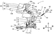
- FIG. 1 is a perspective view which looked at assistance device 1 of an embodiment from the slanting back.
- FIG. 2 is a figure which shows the initial state in case the assistance apparatus 1 assists the transfer operation
- FIG. 3 is a diagram illustrating a final state when the assistance device 1 assists the transfer operation of the person being assisted M, and is a side cross-sectional view of the assistance device 1 taken along the center line.
- the assistance device 1 assists transfer between two different places such as transfer between the bed of the person being assisted M and the wheelchair and transfer between the wheelchair and the toilet seat.
- the assistance device 1 supports the body of the person being assisted M and assists the transfer operation from the sitting posture to the posture at the time of transfer and the sitting operation from the posture at the time of transfer to the sitting posture.
- the transfer posture is a posture in which the buttocks floats from the seating surface, and includes a standing posture and a middle waist posture. That is, the posture at the time of transfer includes a state where the upper body stands up and a state of leaning forward.
- the assistance apparatus 1 can transfer the care recipient M in the posture at the time of transfer when the two places to be transferred are separated.
- the assistance device 1 includes a base 10, a drive unit 2, a support unit 50, a control unit 90, and the like.
- the drive unit 2 includes an arm 20, an actuator 30, a link mechanism 40, and the like. The drive unit 2 moves the support unit 50 relative to the base 10.
- the base 10 is formed of a frame 11, a foot placing table 12, a front wheel 13, a rear wheel 14, a crus pad 15 and the like.
- the frame 11 is formed of a rear member 11a that is disposed horizontally in the vicinity of the floor surface F, and a front member 11b that extends obliquely upward and forward from the front end of the rear member 11a.
- An actuator support portion 11c is projected from the front side of the upper surface of the rear member 11a.
- the footrest 12 is fixed substantially horizontally on the upper surface of the rear member 11a.
- the two front wheels 13 are provided on the front member 11b, and the two rear wheels 14 are provided on the rear member 11a. Due to the steering function of the front wheels 13 and the rear wheels 14, the assistance device 1 can perform not only a straight movement and a turning movement, but also a lateral movement and a super turn. Further, the front wheel 13 has a lock function for restricting movement.
- the lower thigh pad 15 is formed of a pair of support members 16 and a cushion material 17.
- the pair of support members 16 are erected from the front member 11b obliquely rearward and upward.
- the cushion material 17 is provided at the upper end of the support member 16. The cushion material 17 is located above the footrest 12 and can be contacted with the vicinity of the lower leg of the person being assisted M.
- the arm 20 constituting the drive unit 2 is formed of two bar-like members that are spaced apart and parallel to each other.
- the two rod-shaped members are coupled to each other on the lower side using the swing shaft 21 and on the upper side using the support shaft 22.
- the arm 20 has a curved shape in which two rod-like members protrude forward or a bent shape.
- a link support portion 27 is provided near the middle of the arm 20 in the length direction.
- a regulating member 28 having a shape substantially along the arm 20 is provided near the link support portion 27 of the arm 20.
- the arm 20 swings in the front-rear direction with the swing shaft 21 supported by the front member 11b as the swing axis.
- a stopper mechanism 23 is provided to regulate the swing angle of the arm 20.
- the stopper mechanism 23 includes a contact member 24 fixed to the lower side of the arm 20, and a first stopper 25 and a second stopper 26 fixed to the front member 11b.
- the arm 20 extends from a rear position (shown in FIG. 2) where the contact member 24 contacts the first stopper 25 to a front position (shown in FIG. 3) where the contact member 24 contacts the second stopper 26. Swing between.
- the support part 50 is formed including a body support part 52 and a pair of side support parts 53.
- the trunk support 52 is supported by the support shaft 22 of the arm 20 so as to be swingable. Thereby, the support part 50 rocks
- the body support part 52 includes a handle 52a and a locking part 52b.
- the handle 52a is formed in a substantially rectangular frame shape.
- the handle 52 a is a part that is held by the person being assisted M, and is also a part that is held by the assistant in order to move the assistance device 1.
- the locking portion 52b is located near the center of the rectangular frame of the handle 52a.
- the torso support part 52 supports the abdomen from the chest of the to-be-supported person's M torso.
- the pair of side support parts 53 are attached to the chest sides on the left and right sides of the body support part 52.
- the side support portion 53 is formed in an L shape that bends at an obtuse angle.
- a short straight line portion from the base end on the attachment side of the side support portion 53 to the bent position becomes a shoulder receiving portion 53a, and a long straight portion from the bent position to the distal end becomes a side entry portion 53b.
- the shoulder receiving portion 53 a is located in substantially the same plane as the body support portion 52 and supports the front surface of the shoulder of the person being assisted M.
- the side entry portion 53b gradually moves away from the plane, enters the sides of the body of the person being assisted M, and can extend in the back direction of the person being assisted.
- the surface of the side support portion 53 is covered with a cushion material that can be easily deformed and compressed.
- FIG. 4 is a side cross-sectional view of the body support 52 cut along the center line.
- the right side in FIG. 4 corresponds to the chest side of the person being assisted M, and the left side in FIG.
- the trunk support 52 includes a base plate 6, a subplate 7, and a trunk contact member 8.
- the base plate 6 is a substantially rectangular plate-like member in plan view.
- the base plate 6 is made of a metal plate or the like and has high bending rigidity.
- a surface of the base plate 6 facing the person being assisted M is a support surface 65.
- the base plate 6 can support the body of the person being assisted M. Even if a load resulting from the weight of the person being assisted M acts on the support surface 65 via the body contact member 8, the base plate 6 hardly deforms.
- the handle 52a described above is fixed to the base plate 6.
- the base plate 6 has a supported portion 61 (not shown in FIG. 4 and shown in FIG. 5) that is supported on the support shaft 22 of the arm 20 so as to be swingable.
- the base plate 6 has a pair of left and right holding holes 62 in the vicinity of the chest side end.
- the holding hole 62 holds the coupling pin 54 coupled to the base end of the side support portion 53 so that the coupling pin 54 can rotate and cannot be pulled out.
- the side support portion 53 swings around the coupling pin 54 as an axis, and the angle formed with the body support portion 52 can be adjusted.
- the support part 50 respond
- the sub plate 7 is a thin plate member.
- the sub plate 7 is made of resin, for example, polycarbonate, and has a lower bending rigidity than the base plate 6.
- the surface of the sub plate 7 facing the person being assisted M is a support surface 75.
- the overlapping portion 71 on the chest side of the sub plate 7 is disposed so as to overlap the support surface 65 of the base plate 6.
- the extension part 72 on the abdomen side of the sub-plate 7 extends to the abdomen side of the base plate 6 and extends. According to this arrangement, the sub-plate 7 can support the lower side of the trunk of the person being assisted M as compared to the base plate 6. Specifically, when the base plate 6 supports the chest of the person being assisted M, the sub-plate 7 supports the abdomen of the person being assisted.
- the positional relationship between the sub plate 7 and the base plate 6 is not limited to the above.
- the overlapping portion 71 of the sub-plate 7 is overlapped not on the support surface 65 of the base plate 6 but on the back surface on the opposite side.
- transformation aspect which forms the surface which the support surface 75 of the subplate 7 and the support surface 65 of the baseplate 6 share is demonstrated later.
- the body contact member 8 is formed to be larger than the base plate 6 and the sub plate 7 using a material that is more flexible than the sub plate 7.
- the body contact member 8 has a two-layer structure including a surface layer 81 and a base layer 82.
- the surface layer 81 is disposed on the side closer to the body of the person being assisted.
- the surface layer 81 is formed into a curved shape that fits the front surface of the body of the person being assisted M using a material that has flexibility and can be easily deformed.
- a material for forming the surface layer 81 a low resilience urethane foam can be exemplified.
- the surface layer 81 is deformed flexibly and gently supports the body of the person being assisted. Further, the surface layer 81 disperses the load caused by the body weight of the person being assisted. Thereby, the distribution of the load acting on the support surface 65 of the base plate 6 and the support surface 75 of the sub-plate 7 is equalized.
- the base layer 82 is disposed on the side close to the base plate 6 and the sub plate 7.
- the base layer 82 and the surface layer 81 may be bonded or not bonded.
- the base layer 82 is formed using a material that is harder and less deformable than the surface layer 81 and more flexible than the sub-plate 7. Examples of the material for forming the base layer 82 include low-flammability urethane foam.
- the base layer 82 supports the surface layer 81.
- the fuselage contact member 8 is stored in the storage cover 83 and used.
- the storage cover 83 is formed in a double bag shape having a sub cover 84 inside the side in contact with the base plate 6.
- the sub plate 7 is housed in the sub cover 84 and used.
- the storage cover 83 is detachably attached to the support surface 65 of the base plate 6 using, for example, an unillustrated hook-and-loop fastener. Therefore, the sub-plate 7 and the body contact member 8 can be exchanged.
- the actuator 30 constituting the drive unit 2 is formed of a main body unit 31, a movable unit 32, a drive source (not shown), and the like.
- the movable part 32 moves linearly relative to the main body part 31 and protrudes from the return position via the intermediate position.
- a motor serving as a drive source drives the movable portion 32 via a power transmission mechanism such as a transmission gear (not shown).
- the drive source is not limited to this, and may be a pressure drive source that directly moves the movable portion 32 corresponding to the piston using hydraulic pressure or air pressure.
- the base end 31a of the main body 31 is supported by the actuator support 11c of the frame 11 so as to be tiltable. As a result, the actuator 30 tilts in the front-rear direction with the actuator support 11c as a fulcrum.
- the distal end 32 a of the movable part 32 engages with the link mechanism 40.
- the link mechanism 40 constituting the drive unit 2 is formed of a first link member 41, a second link member 42, and the like.
- the first link member 41 is a long member formed of metal, hard resin, or the like.
- the first link member 41 has a supported portion 41a at the center, a driven portion 41b and a roller 41c at one end, and a connecting portion 41d at the other end.
- the supported part 41a is supported by the link support part 27 of the arm 20 so as to be swingable.
- the driven portion 41 b is engaged with the tip 32 a of the movable portion 32 of the actuator 30. When the movable portion 32 further protrudes from the intermediate position, the roller 41c can come into contact with the regulating member 28 of the arm 20 and roll.
- the second link member 42 connects the connecting portion 41d of the first link member 41 and the locking portion 52b of the body support portion 52.
- the second link member 42 is formed using a flexible material such as rubber, elastomer, soft resin, or film-like hard resin.
- the connecting portion 41d and the locking portion 52b move in directions away from each other, the second link member 42 is in an interlocking state in which the connecting portion 41d and the locking portion 52b are interlocked.
- the connecting portion 41d and the locking portion 52b move in a direction approaching each other, the second link member 42 allows an unlinked state in which the connecting portion 41d and the locking portion 52b are not linked.
- the control unit 90 includes a control main body 91 that operates by software, an operating device 92, a battery power source 96, and the like.
- the control main body 91 and the battery power source 96 are fixed on the front side near the lower end of the arm 20.
- the battery power source 96 is shared by the control main body 91 and the actuator 30.
- the operating device 92 is connected to the control main body 91 using a connection cord 93. However, the operation device 92 may be connected to the control main body 91 by wireless communication.
- the operating device 92 is provided with an up button 94 and a down button 95.
- the control main body 91 controls the actuator 30 according to the operation state of the operation device 92.
- the control main body 91 controls the ascending mode in which the movable portion 32 of the actuator 30 protrudes from the main body 31.
- the ascending mode corresponds to assistance of a transfer operation that raises the buttocks of the person being assisted.
- the control main body 91 controls the lowering mode in which the movable portion 32 of the actuator 30 is returned to the main body 31.
- the descending mode corresponds to assistance of a seating operation for lowering the buttocks of the person being assisted.
- the operation of the assisting device 1 of the embodiment will be described.
- assistance of the transfer operation of the person being assisted M is taken as an example.
- the assistance device 1 operates from the initial state shown in FIG. 2 to the final state shown in FIG.
- the assistance device 1 operates in the reverse direction in the generally reverse order of the assistance of the transfer operation.
- the assistant presses down button 95 of operating device 92 to return movable portion 32 of actuator 30 to the return position shown in FIG. Subsequently, the assistant holds the handle 52a and moves the assistant device 1 to approach the person M who is in the sitting posture.
- the person being assisted M causes the lower body to enter the region between the base 10 and the support part 50. Further, the person being assisted M places both feet on the mark 12 a of the foot placing table 12.
- the care receiver M can obtain a stable posture by bringing a part of the lower leg into contact with the cushion material 17 of the lower leg pad 15.
- the person being assisted M tilts the trunk forward to bring it into surface contact with the trunk support 52 and leans against the side support 53 on both sides.
- the trunk support portion 52 swings in the standing direction, so that the forward tilt angle of the trunk is small.
- the side entry portion 53 b of the side support portion 53 is substantially horizontal or slightly rearwardly lowered, the person being assisted M can easily lean on the side support portion 53.
- the posture of the person being assisted at this time is the initial posture. In the initial posture, the buttocks are seated on the seat.
- the series of operations of the person being assisted M described above may be assisted by an assistant.
- the assistant presses the ascending button 94 of the operation device 92 to cause the movable portion 32 to protrude. While the movable portion 32 protrudes from the return position to the intermediate position, the roller 41c of the first link member 41 is not yet in contact with the regulating member 28. For this reason, the first link member 41 is driven by the movable portion 32 and swings counterclockwise in FIG. At the same time, the actuator 30 tilts forward. Further, the arm 20 maintains the rear position of the initial state. As the first link member 41 swings, the support portion 50 swings forward in conjunction with the second link member 42. This operation is continued until the movable part 32 reaches the intermediate position. Thereby, as for the care receiver M, the upper body leans further forward. At this time, since the side entry part 53b of the side support part 53 is forwardly lowered, the person being assisted M is restricted from moving backward and does not fall off the support part 50.
- the assistant further presses the ascending button 94 of the operation device 92 to cause the movable portion 32 to protrude.
- the roller 41c comes into contact with the restricting member 28, and the swinging of the first link member 41 ends.
- the arm 20 is driven by the movable portion 32 and swings clockwise in FIG.
- the actuator 30 tilts further forward.
- the connecting portion 41 d and the locking portion 52 b are in an interlocking state, and the support portion 50 maintains a constant posture with respect to the arm 20. This operation is continued until the end state of FIG. 3 when the arm 20 reaches the front position.
- the person being assisted M further tilts forward while the upper body moves diagonally forward and upward while the buttocks move away from the seating surface.
- the person being assisted M takes the posture at the time of transfer in which the buttock is greatly raised from the seating surface and the leg is extended.
- FIG. 5 is a side view showing an action in which the extension part 72 of the sub-plate 7 of the body support part 52 is deformed and bent.
- the body contact member 8 and the storage cover 83 are omitted.
- the positional relationship between the body of the assisted person M and the body support portion 52 changes.
- the trunk of the person being assisted M is substantially parallel to the trunk support 52.
- the abdomen of the body of the person being assisted M is closer to the base plate 6 and the subplate 7 than the chest.
- the load caused by the weight of the person being assisted M acts on the support surface 65 of the base plate 6 and the support surface 75 of the sub-plate 7 almost equally. At this time, much load does not act on the extension part 72 of the subplate 7, and the extension part 72 hardly deforms. Further, a large surface pressure is not generated as a reaction force of the load on a specific portion of the body of the person being assisted M.
- the overlapping portion 71 of the subplate 7 is disposed so as to overlap the support surface 65 of the base plate 6, the abdomen end of the base plate 6 is hidden by the subplate 7 and does not press the person being assisted.
- a first variation mode in which the overlapping portion 71 of the sub-plate 7 is overlapped with the back surface of the base plate 6 will be recalled.
- the base plate 6 is disposed closer to the person being assisted than the sub-plate 7. When the sub-plate 7 bends, the base plate 6 remains without being deformed at the abdomen end, and the abdomen of the person to be assisted M may be strongly pressed. Therefore, this embodiment is superior to the first modification.
- the sub-plate 7 has a high bending rigidity and does not deform.
- much of the load due to the weight of the person being assisted is concentrated on the abdomen end of the sub-plate 7 that does not deform.
- a large surface pressure is generated in the abdomen of the person being assisted.
- the person being assisted M feels a strong feeling of pressure, and the comfort of use decreases.
- a strong feeling of pressure in the abdomen also occurs in a conventional manner with only the base plate 6 without the sub-plate 7. Therefore, this embodiment is superior to the contrast mode and the conventional mode.
- the metal base plate 6 and the resin-made deformable sub-plate 7 for the body support portion 52 by using the metal base plate 6 and the resin-made deformable sub-plate 7 for the body support portion 52, the strong pressure feeling of the abdomen of the person being assisted M is eliminated, A comfortable user experience can be realized. Further, since the sub plate 7 can be replaced, the thickness and material of the sub plate 7 can be changed according to the physique and preference of the person being assisted. For example, the sub-plate 7 having a lower bending rigidity and being easily deformable can be used in accordance with the obese person M.
- FIG. 6 is a side cross-sectional view of the body support portion 56 according to the second modified embodiment taken along the center line.
- the base plate 6A is made of metal, and has a fitting groove 66 at the abdomen end.
- the sub-plate 7A is made of resin and has a protrusion 76 at the end on the chest side. The protrusion 76 of the sub plate 7A is fitted and fixed in the fitting groove 66 of the base plate 6A.
- the support surface 65 of the base plate 6A and the support surface 75 of the sub plate 7A form a common surface and have no step.
- the storage cover 86 has a single bag shape and stores the body contact member 8.
- the drive unit 2 of the embodiment uses the single actuator 30 to first swing the support unit 50 and then swing the arm 20, but is not limited thereto.
- the drive unit may include a plurality of actuators, or may slide the support unit and the arm.
- the support part 50 may be formed only by the body support parts (52, 56), and the pair of side support parts 53 may be omitted.
- the body contact member 8 does not need to have a two-layer structure, and may be formed of a single material. The embodiment and the first and second modification modes can be variously modified and applied.
- Assistance device 2 Drive unit 10: Base 20: Arm 30: Actuator 40: Link mechanism 50: Support unit 52: Torso support unit 53: Side support unit 53a: Shoulder support unit 53b: Side entry unit 56: Torso support Part 6, 6A: Base plate 65: Support surface 66: Fitting groove 7, 7A: Sub-plate 71: Overlap part 72: Extension part 75: Support surface 76: Projection 8: Body contact member 81: Surface layer 82: Base layer 83: Storage cover 84: Sub-cover 86: Storage cover 90: Control unit M: Caregiver
Abstract
Description
実施形態の介助装置1について、図1~図5を参考にして説明する。図1は、実施形態の介助装置1を斜め後方から見た斜視図である。また、図2は、介助装置1が被介助者Mの移乗動作を介助する場合の初期状態を示す図であって、介助装置1を中心線で切った側面断面図である。さらに、図3は、介助装置1が被介助者Mの移乗動作を介助する場合の終期状態を示す図であって、介助装置1を中心線で切った側面断面図である。 1. Configuration of Assisting Device 1 of Embodiment The assisting device 1 of the embodiment will be described with reference to FIGS. 1 to 5. Drawing 1 is a perspective view which looked at assistance device 1 of an embodiment from the slanting back. Moreover, FIG. 2 is a figure which shows the initial state in case the assistance apparatus 1 assists the transfer operation | movement of the care receiver M, and is side surface sectional drawing which cut the assistance apparatus 1 with the centerline. Further, FIG. 3 is a diagram illustrating a final state when the assistance device 1 assists the transfer operation of the person being assisted M, and is a side cross-sectional view of the assistance device 1 taken along the center line.
次に、実施形態の介助装置1の動作について説明する。以降の説明では、被介助者Mの移乗動作の介助を例にする。この場合、介助装置1は、図2に示される初期状態から図3に示される終期状態まで動作する。なお、被介助者Mの着座動作を介助する場合、介助装置1は、移乗動作の介助の概ね逆順で逆方向に動作する。 2. Operation of Assisting Device 1 of Embodiment Next, the operation of the assisting device 1 of the embodiment will be described. In the following description, assistance of the transfer operation of the person being assisted M is taken as an example. In this case, the assistance device 1 operates from the initial state shown in FIG. 2 to the final state shown in FIG. In addition, when assisting the sitting operation of the person being assisted M, the assistance device 1 operates in the reverse direction in the generally reverse order of the assistance of the transfer operation.
次に、実施形態の介助装置1の作用および効果について説明する。図5は、胴体支持部52のサブプレート7の延出部72が変形してたわむ作用を示した側面図である。図5において、胴体接触部材8および収納カバー83は、省略されている。被介助者Mが初期姿勢(図2参照)から移乗時姿勢(図3参照)まで姿勢変化する過程で、被介助者Mの胴体と胴体支持部52の位置関係が変化する。例えば、図2の初期姿勢で、被介助者Mの胴体は、胴体支持部52に概ね平行している。また、図3の移乗時姿勢で、被介助者Mの胴体は、胸部と比較して腹部がベースプレート6およびサブプレート7に接近している。 3. Operation and Effect of Assistance Device 1 of Embodiment Next, the operation and effect of the assistance device 1 of the embodiment will be described. FIG. 5 is a side view showing an action in which the
なお、上述した胴体支持部52に代えて、図6に示される胴体支持部56を用いることができる。図6は、第2変形態様の胴体支持部56を中心線で切った側面断面図である。第2変形態様において、ベースプレート6Aは、金属製であり、腹部側の端部に嵌合溝66を有する。一方、サブプレート7Aは、樹脂製であり、胸部側の端部に突条76を有する。サブプレート7Aの突条76は、ベースプレート6Aの嵌合溝66に嵌入して固定される。そして、ベースプレート6Aの支持面65およびサブプレート7Aの支持面75は、共通する面を形成して段差が無い。収納カバー86は、一重の袋状とされ、胴体接触部材8を収納する。 4). Second Modification, Other Modifications and Applications It should be noted that a
Claims (5)
- 基台と、
被介助者の胴体を支持可能なベースプレートと、前記ベースプレートよりも曲げ剛性が低く前記被介助者の体重により変形可能であって、前記ベースプレートと比較して前記被介助者の前記胴体の下部の側を支持可能なサブプレートと、前記サブプレートよりも柔軟性があって、前記ベースプレートおよび前記サブプレートの前記被介助者に対向する側の支持面に設けられる胴体接触部材と、を有し、前記被介助者の前記胴体を支持しつつ前記基台に対する相対的な移動が可能な胴体支持部と、
前記胴体支持部を駆動する駆動部と、
を備える介助装置。 The base,
A base plate capable of supporting the body of the person being assisted, and having a lower bending rigidity than the base plate and being deformable according to the weight of the person being assisted, the lower side of the body of the person being assisted compared to the base plate And a body contact member provided on a support surface of the base plate and a side of the sub plate facing the person being assisted, which is more flexible than the sub plate. A body support unit capable of moving relative to the base while supporting the body of the person being assisted;
A drive unit for driving the body support unit;
An assistance device comprising: - 前記サブプレートは交換可能である、請求項1に記載の介助装置。 The assistance device according to claim 1, wherein the sub-plate is replaceable.
- 前記サブプレートの少なくとも一部は、前記ベースプレートの前記支持面に重ねて配置される、請求項1または2に記載の介助装置。 The assistance device according to claim 1 or 2, wherein at least a part of the sub-plate is disposed so as to overlap the support surface of the base plate.
- 前記ベースプレートは金属製であり、前記サブプレートは樹脂製である、請求項1~3のいずれか一項に記載の介助装置。 The assistance device according to any one of claims 1 to 3, wherein the base plate is made of metal and the sub-plate is made of resin.
- 前記ベースプレートが前記被介助者の胸部を支持したときに、前記サブプレートは、前記被介助者の腹部を支持する、請求項1~4のいずれか一項に記載の介助装置。 The assistance device according to any one of claims 1 to 4, wherein when the base plate supports the chest of the person being assisted, the sub-plate supports the abdomen of the person being assisted.
Priority Applications (6)
| Application Number | Priority Date | Filing Date | Title |
|---|---|---|---|
| EP17903491.3A EP3603599B1 (en) | 2017-03-31 | 2017-03-31 | Assistance device |
| SG11201909099U SG11201909099UA (en) | 2017-03-31 | 2017-03-31 | Assistance device |
| AU2017406690A AU2017406690B2 (en) | 2017-03-31 | 2017-03-31 | Assistance device |
| PCT/JP2017/013830 WO2018179430A1 (en) | 2017-03-31 | 2017-03-31 | Assistance device |
| CN201780088443.2A CN110430852B (en) | 2017-03-31 | 2017-03-31 | Auxiliary device |
| JP2019508489A JP6704508B2 (en) | 2017-03-31 | 2017-03-31 | Assistance device |
Applications Claiming Priority (1)
| Application Number | Priority Date | Filing Date | Title |
|---|---|---|---|
| PCT/JP2017/013830 WO2018179430A1 (en) | 2017-03-31 | 2017-03-31 | Assistance device |
Publications (1)
| Publication Number | Publication Date |
|---|---|
| WO2018179430A1 true WO2018179430A1 (en) | 2018-10-04 |
Family
ID=63674759
Family Applications (1)
| Application Number | Title | Priority Date | Filing Date |
|---|---|---|---|
| PCT/JP2017/013830 WO2018179430A1 (en) | 2017-03-31 | 2017-03-31 | Assistance device |
Country Status (6)
| Country | Link |
|---|---|
| EP (1) | EP3603599B1 (en) |
| JP (1) | JP6704508B2 (en) |
| CN (1) | CN110430852B (en) |
| AU (1) | AU2017406690B2 (en) |
| SG (1) | SG11201909099UA (en) |
| WO (1) | WO2018179430A1 (en) |
Cited By (4)
| Publication number | Priority date | Publication date | Assignee | Title |
|---|---|---|---|---|
| US20190142670A1 (en) * | 2016-05-17 | 2019-05-16 | Fuji Corporation | Assisting device |
| CN110496000A (en) * | 2019-09-20 | 2019-11-26 | 北京理工大学 | A kind of wheelchair including support construction |
| KR20210041083A (en) * | 2019-04-11 | 2021-04-14 | 가부시키가이샤 후지 | Market device |
| CN114523484A (en) * | 2022-03-25 | 2022-05-24 | 重庆师范大学 | Robot for dining room of intelligent cart school |
Families Citing this family (2)
| Publication number | Priority date | Publication date | Assignee | Title |
|---|---|---|---|---|
| SG11202004125YA (en) * | 2017-12-06 | 2020-06-29 | Fuji Corp | Aid device |
| WO2021234827A1 (en) * | 2020-05-19 | 2021-11-25 | 株式会社Fuji | Assistive device |
Citations (5)
| Publication number | Priority date | Publication date | Assignee | Title |
|---|---|---|---|---|
| JP2012045068A (en) * | 2010-08-25 | 2012-03-08 | Toyota Motor Corp | Transfer support apparatus, and holder |
| JP2014064635A (en) | 2012-09-25 | 2014-04-17 | Toyota Motor Corp | Body holder and transfer support device |
| JP2015112255A (en) * | 2013-12-11 | 2015-06-22 | 住友理工株式会社 | Caretaker assisting apparatus |
| JP2016093504A (en) * | 2014-11-11 | 2016-05-26 | 社会福祉法人天寿会 | Transfer machine |
| WO2016103497A1 (en) * | 2014-12-26 | 2016-06-30 | 富士機械製造株式会社 | Assistance robot |
Family Cites Families (10)
| Publication number | Priority date | Publication date | Assignee | Title |
|---|---|---|---|---|
| DK42789A (en) * | 1988-02-01 | 1989-08-02 | Echo Corp | DEVICE FOR TRANSFER OF DISABLED PERSONS |
| US5148557A (en) * | 1990-08-27 | 1992-09-22 | Vladimir Fridman | Invalid lift and transport apparatus |
| JP5353568B2 (en) * | 2009-09-01 | 2013-11-27 | トヨタ自動車株式会社 | Transfer device and transfer method |
| JP2012040251A (en) * | 2010-08-20 | 2012-03-01 | Toyota Motor Corp | Holder and transfer support device having the same |
| CN101947180A (en) * | 2010-10-29 | 2011-01-19 | 天津友爱康复医疗设备有限公司 | Auxiliary standing training device |
| US9962307B2 (en) * | 2010-12-20 | 2018-05-08 | Restoration Robotics, Inc. | Adjustable hair transplantation chair |
| US9038212B2 (en) * | 2010-12-28 | 2015-05-26 | Toyota Jidosha Kabushiki Kaisha | Transfer assistance device and operation method therefor |
| IN2014CN03186A (en) * | 2011-10-04 | 2015-07-03 | Formway Furniture Ltd | |
| EP2666695B1 (en) * | 2012-05-26 | 2014-12-03 | Bombardier Transportation GmbH | Driver's desk provided with energy absorption means for a rail vehicle |
| JP2016144628A (en) * | 2015-02-04 | 2016-08-12 | 住友理工株式会社 | Care taker assist device |
-
2017
- 2017-03-31 JP JP2019508489A patent/JP6704508B2/en active Active
- 2017-03-31 AU AU2017406690A patent/AU2017406690B2/en active Active
- 2017-03-31 SG SG11201909099U patent/SG11201909099UA/en unknown
- 2017-03-31 EP EP17903491.3A patent/EP3603599B1/en active Active
- 2017-03-31 WO PCT/JP2017/013830 patent/WO2018179430A1/en active Application Filing
- 2017-03-31 CN CN201780088443.2A patent/CN110430852B/en active Active
Patent Citations (5)
| Publication number | Priority date | Publication date | Assignee | Title |
|---|---|---|---|---|
| JP2012045068A (en) * | 2010-08-25 | 2012-03-08 | Toyota Motor Corp | Transfer support apparatus, and holder |
| JP2014064635A (en) | 2012-09-25 | 2014-04-17 | Toyota Motor Corp | Body holder and transfer support device |
| JP2015112255A (en) * | 2013-12-11 | 2015-06-22 | 住友理工株式会社 | Caretaker assisting apparatus |
| JP2016093504A (en) * | 2014-11-11 | 2016-05-26 | 社会福祉法人天寿会 | Transfer machine |
| WO2016103497A1 (en) * | 2014-12-26 | 2016-06-30 | 富士機械製造株式会社 | Assistance robot |
Non-Patent Citations (1)
| Title |
|---|
| See also references of EP3603599A4 |
Cited By (6)
| Publication number | Priority date | Publication date | Assignee | Title |
|---|---|---|---|---|
| US20190142670A1 (en) * | 2016-05-17 | 2019-05-16 | Fuji Corporation | Assisting device |
| US10792204B2 (en) * | 2016-05-17 | 2020-10-06 | Fuji Corporation | Assisting device |
| KR20210041083A (en) * | 2019-04-11 | 2021-04-14 | 가부시키가이샤 후지 | Market device |
| KR102520828B1 (en) | 2019-04-11 | 2023-04-11 | 가부시키가이샤 후지 | market device |
| CN110496000A (en) * | 2019-09-20 | 2019-11-26 | 北京理工大学 | A kind of wheelchair including support construction |
| CN114523484A (en) * | 2022-03-25 | 2022-05-24 | 重庆师范大学 | Robot for dining room of intelligent cart school |
Also Published As
| Publication number | Publication date |
|---|---|
| CN110430852B (en) | 2021-03-12 |
| JPWO2018179430A1 (en) | 2019-11-07 |
| AU2017406690A1 (en) | 2019-10-17 |
| EP3603599A1 (en) | 2020-02-05 |
| JP6704508B2 (en) | 2020-06-03 |
| CN110430852A (en) | 2019-11-08 |
| EP3603599B1 (en) | 2020-10-28 |
| AU2017406690B2 (en) | 2020-11-26 |
| SG11201909099UA (en) | 2019-10-30 |
| EP3603599A4 (en) | 2020-03-11 |
Similar Documents
| Publication | Publication Date | Title |
|---|---|---|
| WO2018179430A1 (en) | Assistance device | |
| WO2018168112A1 (en) | Assistive device | |
| WO2019111356A1 (en) | Aid device | |
| JP2015000070A (en) | Massage machine | |
| WO2011036880A1 (en) | Massager | |
| WO2018179431A1 (en) | Assistance device | |
| WO2018179294A1 (en) | Assistance device | |
| WO2020070848A1 (en) | Assistance apparatus | |
| JP7420931B2 (en) | Assistive device | |
| JP6898507B2 (en) | Assistance device | |
| JPWO2020208700A1 (en) | Caregiving device | |
| JP2005131219A (en) | Standing assisting chair |
Legal Events
| Date | Code | Title | Description |
|---|---|---|---|
| 121 | Ep: the epo has been informed by wipo that ep was designated in this application |
Ref document number: 17903491 Country of ref document: EP Kind code of ref document: A1 |
|
| WWE | Wipo information: entry into national phase |
Ref document number: 2019508489 Country of ref document: JP |
|
| NENP | Non-entry into the national phase |
Ref country code: DE |
|
| ENP | Entry into the national phase |
Ref document number: 2017406690 Country of ref document: AU Date of ref document: 20170331 Kind code of ref document: A |
|
| WWE | Wipo information: entry into national phase |
Ref document number: 2017903491 Country of ref document: EP |
|
| ENP | Entry into the national phase |
Ref document number: 2017903491 Country of ref document: EP Effective date: 20191031 |