WO2018176222A1 - 传输、获取同步信息块的方法及装置 - Google Patents
传输、获取同步信息块的方法及装置 Download PDFInfo
- Publication number
- WO2018176222A1 WO2018176222A1 PCT/CN2017/078439 CN2017078439W WO2018176222A1 WO 2018176222 A1 WO2018176222 A1 WO 2018176222A1 CN 2017078439 W CN2017078439 W CN 2017078439W WO 2018176222 A1 WO2018176222 A1 WO 2018176222A1
- Authority
- WO
- WIPO (PCT)
- Prior art keywords
- synchronization information
- mode
- information block
- target
- synchronization
- Prior art date
Links
Images


Classifications
-
- H—ELECTRICITY
- H04—ELECTRIC COMMUNICATION TECHNIQUE
- H04W—WIRELESS COMMUNICATION NETWORKS
- H04W48/00—Access restriction; Network selection; Access point selection
- H04W48/08—Access restriction or access information delivery, e.g. discovery data delivery
- H04W48/10—Access restriction or access information delivery, e.g. discovery data delivery using broadcasted information
-
- H—ELECTRICITY
- H04—ELECTRIC COMMUNICATION TECHNIQUE
- H04W—WIRELESS COMMUNICATION NETWORKS
- H04W56/00—Synchronisation arrangements
- H04W56/001—Synchronization between nodes
-
- H—ELECTRICITY
- H04—ELECTRIC COMMUNICATION TECHNIQUE
- H04W—WIRELESS COMMUNICATION NETWORKS
- H04W48/00—Access restriction; Network selection; Access point selection
- H04W48/08—Access restriction or access information delivery, e.g. discovery data delivery
- H04W48/12—Access restriction or access information delivery, e.g. discovery data delivery using downlink control channel
-
- H—ELECTRICITY
- H04—ELECTRIC COMMUNICATION TECHNIQUE
- H04B—TRANSMISSION
- H04B7/00—Radio transmission systems, i.e. using radiation field
- H04B7/24—Radio transmission systems, i.e. using radiation field for communication between two or more posts
- H04B7/26—Radio transmission systems, i.e. using radiation field for communication between two or more posts at least one of which is mobile
- H04B7/2662—Arrangements for Wireless System Synchronisation
- H04B7/2671—Arrangements for Wireless Time-Division Multiple Access [TDMA] System Synchronisation
- H04B7/2678—Time synchronisation
-
- H—ELECTRICITY
- H04—ELECTRIC COMMUNICATION TECHNIQUE
- H04W—WIRELESS COMMUNICATION NETWORKS
- H04W56/00—Synchronisation arrangements
-
- H—ELECTRICITY
- H04—ELECTRIC COMMUNICATION TECHNIQUE
- H04W—WIRELESS COMMUNICATION NETWORKS
- H04W56/00—Synchronisation arrangements
- H04W56/001—Synchronization between nodes
- H04W56/0015—Synchronization between nodes one node acting as a reference for the others
-
- H—ELECTRICITY
- H04—ELECTRIC COMMUNICATION TECHNIQUE
- H04W—WIRELESS COMMUNICATION NETWORKS
- H04W72/00—Local resource management
- H04W72/04—Wireless resource allocation
- H04W72/044—Wireless resource allocation based on the type of the allocated resource
- H04W72/046—Wireless resource allocation based on the type of the allocated resource the resource being in the space domain, e.g. beams
-
- H—ELECTRICITY
- H04—ELECTRIC COMMUNICATION TECHNIQUE
- H04W—WIRELESS COMMUNICATION NETWORKS
- H04W72/00—Local resource management
- H04W72/30—Resource management for broadcast services
-
- H—ELECTRICITY
- H04—ELECTRIC COMMUNICATION TECHNIQUE
- H04W—WIRELESS COMMUNICATION NETWORKS
- H04W74/00—Wireless channel access, e.g. scheduled or random access
- H04W74/08—Non-scheduled or contention based access, e.g. random access, ALOHA, CSMA [Carrier Sense Multiple Access]
- H04W74/0833—Non-scheduled or contention based access, e.g. random access, ALOHA, CSMA [Carrier Sense Multiple Access] using a random access procedure
Definitions
- the present disclosure relates to the field of communications technologies, and in particular, to a method and an apparatus for transmitting and acquiring a synchronization information block.
- the user equipment UE Before requesting access to the cell network, the user equipment UE first needs to receive the primary and secondary synchronization signals sent by the base station to perform signal synchronization. After the synchronization is successful, the system information of the cell system sent by the base station is further received and analyzed, and the system is configured as a random access network. prepare.
- the base station transmits the synchronization signal in a fixed period, and after the first synchronization succeeds, the UE can estimate the reception time of the subsequent synchronization signal according to the fixed transmission period of the synchronization signal, thereby accurately performing signal synchronization.
- the design of the synchronization signal of the system has not been determined, that is, the mode in which the synchronization signal is sent by the base station in the 5G network may not be fixed, and the user equipment cannot quickly and accurately detect the synchronization signal.
- the embodiments of the present disclosure provide a method and a device for transmitting and acquiring a synchronization information block, so that user equipment in a 5G network performs signal synchronization quickly and accurately.
- a method for transmitting a synchronization information block which is applied in a base station, the method comprising:
- the target synchronization information block is periodically sent to the user equipment in the target cell by using the high frequency beam;
- Each of the SS burst sets includes a first predetermined number of synchronization bursts SS bursts that are periodically transmitted; each of the SS bursts includes a second predetermined number of the target synchronizations that are sequentially transmitted in a spatial order Information block.
- determining, according to the preset SS burst Set mode, the target mode index information including:
- the preset index information list is queried according to the mode type of the preset SS burst Set mode, and the mode index information corresponding to the preset SS burst Set mode is obtained.
- the target mode index information is stored in each synchronization information block SS block in any of the following manners to obtain a target synchronization information block:
- the target mode index information is stored at a specified position of the physical broadcast channel PBCH of each synchronization information block in the preset SS burst Set mode.
- the method before the determining the target mode index information according to the preset SS burst set mode, the method further includes:
- the SS burst Set mode to be transmitted is determined according to the target cell information.
- the determining, according to the target cell information, a mode of the SS burst set to be transmitted including:
- the target cell information includes at least one of the following: a cell identifier, a user equipment type in the cell, and a busyness of the cell service;
- a method for acquiring a synchronization information block is provided, which is applied to a user equipment, where the method includes:
- the target synchronization information block is acquired according to the estimated arrival time.
- the acquiring the mode index information of the SS burst set from the detected synchronization information block includes:
- the mode index information of the SS burst Set is obtained from the synchronization information block.
- the acquiring the mode index information of the SS burst set from the detected synchronization information block includes:
- the same mode index information in the preset number of mode index information is determined as the valid mode index information.
- the determining, according to the mode index information, the estimated arrival time of the subsequent synchronization information block including:
- the estimated arrival time of the subsequent synchronization information block is determined according to the reception timing of the current synchronization information block and the time interval of the two adjacent synchronization information blocks.
- an apparatus for transmitting a synchronization information block which is disposed in a base station, the apparatus comprising:
- a mode index determining module configured to determine target mode index information according to a preset synchronization information block burst set SS burst Set mode
- a storage module configured to store the target mode index information in each synchronization information block SS block, to obtain a target synchronization information block to be sent;
- a sending module configured to periodically send the target synchronization information block to a user equipment in a target cell by using a high frequency beam
- Each of the SS burst sets includes a first predetermined number of synchronization bursts SS bursts that are periodically transmitted; each of the SS bursts includes a second predetermined number of the target synchronizations that are sequentially transmitted in a spatial order Information block.
- the mode index determining module includes:
- the mode index determining submodule is configured to query the preset index information list according to the mode type of the preset SS burst Set mode, and obtain the mode index information corresponding to the preset SS burst Set mode.
- the storage module includes any one of the following submodules:
- a first storage submodule configured to store target mode index information in a physical broadcast channel PBCH of each synchronization information block in a preset SS burst Set mode
- a second storage submodule configured to store target mode index information in other channels of each synchronization information block in the preset SS burst Set mode
- the third storage submodule is configured to store the target mode index information in a specified location of the physical broadcast channel PBCH of each synchronization information block in the preset SS burst Set mode.
- the device for transmitting the synchronization information block further includes:
- the mode determining module is configured to determine an SS burst set mode to be transmitted according to the target cell information.
- the mode determining module includes:
- the cell information acquisition sub-module is configured to acquire the target cell information, where the target cell information includes at least one of the following: a cell identifier, a user equipment type in the cell, and a busyness of the cell service;
- the mode determining submodule is configured to determine an SS burst set mode suitable for the target cell according to the target cell information.
- an apparatus for acquiring a synchronization information block which is provided in a user equipment, the apparatus comprising:
- the initial detection module is configured to detect the synchronization information block carried by the high frequency beam according to the preset initial detection window;
- An index information obtaining module configured to acquire mode index information of the SS burst set from the detected synchronization information block
- a time prediction module configured to determine an estimated arrival time of the subsequent synchronization information block according to the mode index information
- the synchronization information acquisition module is configured to acquire the target synchronization information block according to the estimated arrival time in the subsequent signal synchronization process.
- the index information acquiring module includes:
- the first obtaining submodule is configured to acquire mode index information of the SS burst set from the synchronization information block after detecting the first synchronization information block.
- the index information acquiring module includes:
- a synchronization block acquisition submodule configured to parse each mode index information from the detected preset number of synchronization information blocks
- the second obtaining submodule is configured to determine the same mode index information in the preset number of mode index information as the valid mode index information.
- the time prediction module includes:
- An interval duration determining submodule configured to determine a time interval of two adjacent sync blocks according to the mode index information
- the time budget sub-module is configured to determine an estimated arrival time of the subsequent synchronization information block according to the reception time of the current synchronization information block and the time interval of the two adjacent synchronization information blocks.
- an apparatus for transmitting a synchronization information block comprising: a processor; a memory for storing processor-executable instructions; wherein the processor is configured to:
- Each of the SS burst sets includes a first predetermined number of synchronization bursts SS bursts that are periodically transmitted; each of the SS bursts includes a second predetermined number of the target synchronizations that are sequentially transmitted in a spatial order Information block.
- an apparatus for acquiring a synchronization information block comprising: a processor; a memory for storing processor-executable instructions; wherein the processor is configured to:
- the target synchronization information block is acquired according to the estimated arrival time.
- the mode index information corresponding to the adopted synchronization information block burst set SS burst Set mode may be stored in each synchronization information block. And transmitting a synchronization signal to the user equipment in the cell by using the high frequency beam carrying the target synchronization information block, so that after the user equipment in the cell acquires a synchronization information block, the mode index information may be obtained from the synchronization information block.
- the estimated arrival time of the subsequent synchronization information block can be accurately calculated.
- the synchronization signal detection window is only required to obtain the target synchronization according to the estimated arrival time.
- the information block can be used not only to quickly and accurately acquire the synchronization information block, but also to reduce the power consumption of the device.
- the base station may query the preset index information list according to the mode type, and obtain the mode index information corresponding to the preset SS burst Set mode, and the list query mode may be adopted. Quickly query mode index information.
- the base station may store mode index information in a physical broadcast channel PBCH of each synchronization information block, other channels, and a specified location of the above-mentioned channel, so that the user equipment can
- the mode index information is quickly acquired according to the mode information storage protocol, thereby improving the signal synchronization efficiency of the user equipment.
- the base station may first determine a suitable SS burst set mode to be transmitted for the target base station according to the cell information of the target cell, and effectively utilize the radio resource.
- the base station when the base station selects the SS burst set mode to be transmitted for the target cell, the base station may select the most suitable SS burst for the target cell by considering the cell identifier of the cell, the type of the user equipment in the cell, and the busyness of the cell service. Set mode, in order to effectively use wireless resources, avoid resource waste, and also reduce base station power consumption.
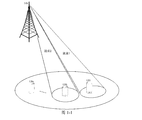
- 1-1 is a schematic diagram of high frequency beam scanning in a 5G system according to an exemplary embodiment of the present disclosure.
- 1-2 is a schematic structural diagram of an SS burst according to an exemplary embodiment of the present disclosure.
- 1-3 are schematic structural diagrams of an SS burst set according to an exemplary embodiment of the present disclosure.
- 1-4 are schematic diagrams of transmissions of an SS burst set, according to an exemplary embodiment of the present disclosure.
- FIG. 2 is a flow chart of a method for transmitting a synchronization signal block according to an exemplary embodiment of the present disclosure.
- FIG. 3 is a schematic structural diagram of six SS burst set modes according to an exemplary embodiment of the present disclosure.
- FIG. 4 is another transmission synchronization information block according to an exemplary embodiment of the present disclosure. Method flow chart.
- FIG. 5 is a flowchart of another method for transmitting a synchronization information block according to an exemplary embodiment of the present disclosure.
- FIG. 6 is a flowchart of another method for transmitting a synchronization information block according to an exemplary embodiment of the present disclosure.
- FIG. 7 is a flowchart of a method for acquiring a synchronization information block according to an exemplary embodiment of the present disclosure.
- FIG. 8 is a flowchart of another method for acquiring a synchronization information block according to an exemplary embodiment of the present disclosure.
- FIG. 9 is a flowchart of another method for acquiring a synchronization information block according to an exemplary embodiment of the present disclosure.
- FIG. 10 is a block diagram of an apparatus for transmitting a synchronization information block according to an exemplary embodiment of the present disclosure.
- FIG. 11 is a block diagram of another apparatus for transmitting a synchronization information block according to an exemplary embodiment of the present disclosure.
- FIG. 12 is a block diagram of another apparatus for transmitting a synchronization information block according to an exemplary embodiment of the present disclosure.
- FIG. 13 is a block diagram of another apparatus for transmitting a synchronization information block according to an exemplary embodiment of the present disclosure.
- FIG. 14 is a block diagram of another apparatus for transmitting a synchronization information block according to an exemplary embodiment of the present disclosure.
- FIG. 15 is a block diagram of an apparatus for acquiring a synchronization information block according to an exemplary embodiment of the present disclosure.
- FIG. 16 is a block diagram of another apparatus for acquiring synchronization information blocks according to an exemplary embodiment of the present disclosure.
- FIG. 17 is a block diagram of another apparatus for acquiring synchronization information blocks according to an exemplary embodiment of the present disclosure.
- FIG. 18 is a block diagram of another apparatus for acquiring synchronization information blocks according to an exemplary embodiment of the present disclosure.
- FIG. 19 is a schematic structural diagram of an apparatus for transmitting a synchronization information block according to an exemplary embodiment of the present disclosure
- FIG. 20 is a schematic structural diagram of an apparatus for acquiring a synchronization information block according to an exemplary embodiment of the present disclosure.
- first, second, third, etc. may be used in the present disclosure to describe various information, such information should not be limited to these terms. These terms are only used to distinguish the same type of information from each other.
- first information may also be referred to as second information without departing from the scope of the present disclosure.
- second information may also be referred to as first information.
- word "if” as used herein may be interpreted as "when” or “when” or “in response to a determination.”
- the technical solution provided by the present disclosure is applicable to a 5G network or other network communication system that uses high frequency beams for information transmission.
- the high frequency beam may be a beam with a frequency point of 6 GHz or higher.
- the execution body involved in the present disclosure includes: a transmitting end and receiving of a high frequency beam
- the transmitting end of the high frequency beam may be a base station, a sub base station or the like provided with a large-scale antenna array.
- the receiving end of the high frequency beam may be a user equipment (User Equipment, UE) provided with a smart antenna array.
- the user equipment UE may be a user terminal, a user node, a mobile terminal, or a tablet.
- the base station and the user equipment are independent of each other, and are in contact with each other to jointly implement the technical solution provided by the present disclosure.
- the 5G or NR (New Radio) network related standard is being implemented in 3GPP (3rd Generation Partnership Project).
- One of the key technologies of the 5G network communication system is: beamforming technology.
- the beam scanning method is adopted in the 5G high-frequency system, and the coverage cell is quickly scanned by the centralized power.
- FIG. 1-1 the 5G system is high according to an exemplary embodiment. Schematic diagram of frequency beam scanning.
- a synchronization information block SS block a synchronization signal burst SS burst
- a synchronization signal burst set SS burst Set a synchronization signal burst set SS burst Set
- the synchronization information block SS block includes a Primary Synchronization Signal (PSS) and a Secondary Synchronization Signal (SSS).
- PSS Primary Synchronization Signal
- SSS Secondary Synchronization Signal
- the SS block is loaded into the high frequency beam to form an SS block beam.
- the base station uses the SS block beam to perform beam scanning on the user equipment in the base station signal coverage cell, and broadcasts synchronization information to the user equipment in the cell through the downlink.
- the user equipment After receiving the synchronization information block and parsing, the user equipment performs signal synchronization with the cell network to prepare the UE for accessing the cell network.
- the synchronization signal burst SS burst refers to that the base station scans the user equipment of a working frequency band in the cell by the SS block beam during the beam scanning process, and needs to sequentially transmit the preset number of SS block beams.
- SS burst can be understood as a set of SS block beams, and each SS block beam carries one SS block.
- the number of SS block beams included in one SS burst is related to the transmission angle of a single beam, that is, the signal coverage area of a single beam. Every SS in an SS burst The band of the block beam is the same.
- the SS burst transmission is a periodic transmission, that is, the base station does not continuously transmit the SS burst, but transmits an SS burst every preset time interval. For example, after an SS burst transmission is completed, another SS burst is started to start at intervals of 5 ms.
- the SS burst set of the synchronization signal burst means that the user equipment of the different working frequency bands in the 5G system is scanned by the SS block beam, and at most several SS bursts need to be transmitted, and according to the interval time of the adjacent two SS bursts. That is, the SS burst transmission period T1, a determined synchronization burst set, corresponding to a duration, can be expressed as T0. That is to say, the duration of the SS burst set is related to the type of the communication band specified in the 5G system and the above-mentioned SS burst transmission period T1.
- the 5G system specifies the following four communication bands: 6 GHz band, 8 GHz band, 10 GHz band, 50 GHz band, and specifies that the SS burst transmission period T1 in the SS burst set is 5 ms, that is, the interval between adjacent SS bursts is 5ms, the duration of an SS burst Set is quite negligible, regardless of the SS burst transmission duration (relative to the SS burst transmission period T1, the SS burst is very short, possibly a few ⁇ s, negligible).
- the interval duration of four SS bursts that is, 20 ms, refer to FIG.
- 1-3 which is a schematic structural diagram of an SS burst set according to an exemplary embodiment.
- the communication frequency band of each SS burst is Not the same, the communication frequency bands of burst 1, burst 2, burst 3, and burst 4 become larger in turn.
- the transmission of the SS burst set is a continuous transmission, as shown in Figure 1-4.
- the present disclosure provides a method of transmitting a synchronization signal block, which is applied to a base station.
- FIG. 2 is a flowchart of a method for transmitting a synchronization signal block according to an exemplary embodiment, and the method may include:
- step 11 according to the preset synchronization information block burst set SS burst Set mode, Target mode index information;
- the base station may broadcast the synchronization information block by using multiple modes of SS burst Set.
- the configuration information corresponding to each SS burst Set mode is different.
- the basic information of the SS burst Set includes: the duration of the SS burst Set T0, the number of bursts, and the SS burst transmission period T1.
- the configuration information of an SS burst set mode mainly includes: the type of burst, the number of each burst, and the positional relationship between bursts.
- a base station may use the SS burst Set mode of FIG. 3 to broadcast a synchronization information block according to actual needs.
- Mode 1 indicates that the base station performs four synchronization signal scans on the target cell using the SS block beam of the same frequency band within an SS burst set duration of 20 ms. That is to say, for a user equipment that does not move in a cell, within 20 ms, it will be covered by the SS block beam at four different times, wherein the time difference between each adjacent two moments is 5 ms.
- Mode 2 and Mode 3 indicate that the base station performs two synchronization signal scans on the target cell using the same frequency band within the duration of an SS burst set. That is to say, for a user equipment that does not move in a cell, within 20 ms, it will be covered by the SS block beam at two different times of 10 ms interval. As shown in FIG. 3, burst 0 in mode 2 and mode 3 may indicate that the synchronization signal block SS block is not configured in the scanning beam of the base station in the corresponding time period, and may be referred to as an invalid burst.
- mode 2 The difference between mode 2 and mode 3 is that the effective burst is the positional relationship between burst 1 and invalid burst in the time domain.
- Mode 4 which indicates that the SS block beam of the two frequency bands is used to scan the target cell twice during the duration of an SS burst set.
- mode 4 indicates that the base station uses the 6 GHz SS block beam to scan the target cell for one week to complete a synchronization signal coverage, corresponding to burst 1;
- the interval T1 is as long as 5ms, and then start using 8GHz.
- the SS block beam scans the target cell for one week, corresponding to burst 2.
- Each burst 1 and burst 2 is a combination that occupies half of the SS burst set duration, which is 10 ms.
- Mode 5 which indicates that the SS block beam of the four frequency bands is used to perform synchronous signal scanning on the target cell within a duration of an SS burst set.
- the base station performs a synchronization signal coverage on the target cell by using the SS block beam of each frequency band.
- a certain frequency band such as 6 GHz
- Mode 6 indicates that the base station performs a synchronous signal scan on the target cell by using an SS block beam of one frequency band within a duration of an SS burst set. Similarly, for a user equipment that does not move in the cell and works in the corresponding frequency band, there is only one chance of being scanned by the SS block beam.
- mode index information of a preset format and size may be used to represent each mode type.
- the index information list can be used to record the correspondence between the SS burst Set mode type and the mode index information. For example, as shown in Table 1:
- Table 1 records the mode index information corresponding to each SS burst Set mode shown in FIG.
- the foregoing step 11 may include:
- step 111 the preset index is queried according to the mode type of the preset SS burst Set mode.
- the information list obtains mode index information corresponding to the preset SS burst Set mode.
- the base station is ready to transmit the synchronization information block to the target cell by using the SS burst set corresponding to the mode in FIG. 3, and then querying the foregoing table 1 according to the mode type, that is, mode one, the mode-corresponding mode index information can be determined as: 4/4.
- step 12 the target mode index information is stored in each synchronization information block to obtain a target synchronization information block to be transmitted;
- the base station stores the mode index information of the SS burst set mode currently used by the base station in each synchronization information block to inform the user equipment which mode of the SS burst set is currently used for synchronization signal transmission.
- the mode index information determined by the base station is small, and can be completely represented by occupying a few bits. As shown in Table 1, the mode index information, such as 4/4, can be fully represented by only 3 bits, which can effectively save wireless transmission resources.
- the target mode index information may be stored in each synchronization information block SS block in the following manners to obtain a target SS block to be sent:
- the target mode index information is stored in a physical broadcast channel PBCH of each synchronization information block in the preset SS burst Set mode;
- the physical broadcast channel PBCH is used to transmit important parameters of the cell, such as MIB (Master Information Block) information for system information configuration, which has the highest priority. Therefore, this method is convenient for user equipment.
- MIB Master Information Block
- the synchronization information block is obtained, and the priority of acquiring the synchronization information block is improved, thereby improving the efficiency of acquiring the synchronization information block.
- the base station may further store the target mode index information in a specified field of the physical broadcast channel PBCH, for example, 10th to 12th bits, so that the user equipment can quickly obtain the target mode index information, and further improve the efficiency of acquiring the synchronization information block.
- PBCH physical broadcast channel
- the target mode index information is stored in other channels of each synchronization information block in the preset mode SS burst Set;
- the base station may also store the target mode index information in other channels, for example, for dynamically broadcasting cell information such as various SIBs (System Information). Block, system information block) in the physical channel DBCH.
- SIBs System Information
- Block system information block
- the base station can also store the target mode index information in a specified location of other channels, so that the user equipment can quickly find the synchronization information block, which is not described here.
- step 13 the target synchronization information block is periodically transmitted to the user equipment in the target cell by the high frequency beam.
- the base station After generating the target SS block, the base station loads the high-frequency beam of each valid burst included in the preset SS burst Set mode to form an SS block beam, and performs synchronization signal scanning on the target cell by using the SS block beam.
- the transmission process of the target synchronization information block is described below with reference to a specific example. It is assumed that the base station determines to use the SS burst set mode in FIG. 3 to transmit the synchronization information block to the user equipment in a target cell.
- the transmission process is as follows:
- the base station when the base station starts transmitting the first burst to the target cell, the base station first loads the mode index information of mode 5, such as 1/1, into a synchronization information block.
- the block 1 in Figure 1-2 is formed, and then the high frequency beam of the corresponding frequency band, such as 6 GHz, is used as the beam 1 in Figure 1-1, and is transmitted to the target cell according to a certain direction and a preset transmission angle, so that the target cell corresponds to the signal coverage area.
- the user equipment such as UE1 can acquire the synchronization information block SS block 1.
- block 2 to block n are obtained according to the above method, and the high frequency beam of the corresponding frequency band, such as 6 GHz, is sequentially transmitted to the target cell, so that all areas of the target cell can be covered by the SS block beam.
- the high frequency beam of another frequency band is used to transmit the burst 2 of mode 5 in FIG. 3, and so on.
- the transmission of one SS burst set in FIG. 1-4 is completed. .
- the user equipment can accurately calculate the reception synchronization signal by adopting a method of adding mode index information in the SS block. Time, so as to quickly and accurately obtain the required synchronization information block, to avoid the use of blind detection mode, resulting in increased power consumption of the device and affect the efficiency of the device.
- FIG. 1 Another method for transmitting a synchronization information block according to an exemplary embodiment, referring to FIG. A flow chart, on the basis of the embodiment shown in FIG. 2, before the step 11, the method may further include:
- step 10 the SS burst set mode to be transmitted is determined according to the target cell information.
- a base station may cover several cells, such as three cells, and the distribution of user equipment in each cell may be the same or different. If the UEs in each cell are similar or identical, the base station may use the SS burst Set in the unified mode to transmit synchronization information blocks to each cell.
- the SS burst set in the unified mode may cause waste of radio resources or fail to obtain synchronization information blocks for all UEs in the cell.
- the base station may first select an appropriate SS burst set mode for the target cell according to the target cell information.
- FIG. 6 is a flowchart of another method for transmitting a synchronization information block according to an exemplary embodiment.
- the step 10 may include:
- the target cell information is acquired, where the target cell information includes at least one of the following: a cell identifier, a user equipment type in the cell, and a busyness of the cell service;
- step 102 an SS burst set mode suitable for the target cell is determined according to the target cell information.
- the cell information of one target cell may include at least one of the following: a cell identifier, a user equipment type in the cell, and a busyness of the cell service.
- step 102 may include, but is not limited to, the following situations:
- the SS burst Set mode is determined according to the cell identity of the target cell. It is assumed that the target cell information includes only the cell identity.
- the base station may preset a synchronization mode list according to the type of each cell. It is assumed that the above cell types are classified into a dedicated device cell and a normal cell. Then, when the base station initializes, the SS burst set mode may be specified for each cell identifier according to the cell type. For example, a base station covers three cells, including: cell A, cell B, and cell C. If the cells A and B are ordinary cells, that is, the cell needs to meet user equipment communication of each frequency band; the cell C is a dedicated device cell. For example, for specific requirements, such as security requirements, the cell only allows a certain frequency band, such as a 6G user equipment, to communicate, and does not allow other working frequency user equipments to access. If the SS burst set mode that the base station can adopt is as shown in FIG. 3, the preset synchronization mode list may be as shown in Table 2:
- the base station can use the SS burst set represented by the mode 5 in FIG. 3 to send the SS block to the user equipment in the cell A.
- the SS burst Set mode is determined according to the user equipment type of the target cell.
- the target cell information includes at least the device type that the cell allows access to the user equipment.
- the base station After determining the target cell identifier, the base station records according to the historical information of the cell, and finds that the user equipment accesses only two frequency bands in the first quarter, for example, the base station can adopt the first quarter according to the above information.
- the SS burst Set represented by mode 4 in FIG. 3 broadcasts the SS block to the user equipment in the target cell.
- the SS burst set mode is determined according to the busyness of the cell service.
- the base station can determine the busy condition of the target cell in each time period according to the historical information record of the cell service, and then adopt different SS burst Set modes.
- the target cell C can transmit the SS block by using mode one, mode two, mode three, and mode six.
- the historical statistics show that the cell C has the highest traffic busyness from 8:00 to 12:00 in the day, the busyness of the traffic from 12:00 to 22:00 is medium, and the traffic is the lowest in 22:00-8:00.
- the base station can send SS blocks in different SS burst set modes in different time periods, as shown in Table 3:
- the base station can use the appropriate SS burst set mode to send the SS block according to the busyness of the cell service, thereby effectively saving the radio resources occupied by the synchronization information block, improving the utilization of the radio resources, and reducing the base station. Power consumption.
- the present disclosure also provides a method for acquiring a synchronization information block, which is applied to a user equipment.
- FIG. 7 is a flowchart of a method for acquiring a synchronization information block according to an exemplary embodiment, which may include the following steps:
- step 21 the synchronization information block carried by the high frequency beam is detected according to the preset initial detection window
- a preset initial detection window is opened, for example, a detection window with a duration of 5 ms, and a blind check of the synchronization information block is performed, so that the first synchronization information block is quickly detected.
- the size of the initial detection window is generally determined according to the number of bursts including different frequency bands in one SS burst set, that is, according to the SS burst Set represented by the mode 5 in FIG. Determine the initial detection window. Still assuming that the duration of a SS burst set T0 is 20ms, and the SS burst set represented by mode five includes four bursts, the size of the initial detection window can be determined to be 5ms, considering that a certain margin is required in the actual detection, The actual window can be slightly larger than 5ms and can be expressed as 5ms+.
- step 22 the mode index information of the SS burst Set is obtained from the detected synchronization information block;
- each SS block in an SS burst Set mode transmitted by the base station includes mode index information of the SS burst set.
- the user equipment may index the information storage protocol according to the preset mode, such as a preset location of the synchronization information block, such as a physical channel PBCH, other preset channels, or a specified field of the preset channel.
- Mode indexing letter for parsing SS burst Set interest such as a preset location of the synchronization information block, such as a physical channel PBCH, other preset channels, or a specified field of the preset channel.
- the UE After detecting the first synchronization information block, the UE acquires the mode index information of the SS burst set from the first synchronization information block according to a preset mode index information storage protocol.
- FIG. 8 is a flowchart of another method for acquiring a synchronization information block according to an exemplary embodiment.
- the foregoing step 22 may include the following steps:
- each mode index information is parsed from the detected preset number of synchronization information blocks
- the UE may continuously acquire a preset number of synchronization information blocks, for example, four, and obtain mode index information of the SS burst set from each synchronization information block.
- step 222 the same mode index information in the preset number of mode index information is determined as the valid mode index information.
- a total of four mode index information is obtained through step 221.
- the four mode index information should be the same, but considering that the UE may have an error in decoding, for example, parsing the mode index information 2/4 into 4/ 4.
- the same information in the parsed preset number of mode index information is determined as the effective mode index information, and the mode index information is improved, in order to prevent the foregoing parsing error from being caused. accuracy.
- step 23 determining, according to the mode index information, an expected large time of the subsequent synchronization information block
- the mode index information may be the mode index information determined by the user equipment according to the first manner, or may be the effective mode index information determined by the user equipment according to the second manner.
- FIG. 9 is a flowchart of another method for acquiring a synchronization information block according to an exemplary embodiment.
- the foregoing step 23 may include the following steps:
- step 231 determining a time interval of two adjacent synchronization information blocks according to the mode index information
- the UE may calculate the time interval between two adjacent synchronization information blocks according to the mode type of the SS burst Set to which the synchronization information block belongs, that is, two identical synchronization bursts. The time interval between.
- the mode index information acquired by the UE is: 1/1, and corresponding to the SS burst Set indicated by mode 5 in FIG. 3, the time interval of two adjacent synchronization bursts may be determined to be 20 ms.
- the mode index information is: 4/4, corresponding to the SS burst Set represented by mode one in FIG. 3, the time interval of two adjacent synchronization bursts is 5 ms.
- the time interval of two adjacent synchronization bursts is represented as T2
- the correspondence between the following table four record mode index information, SS burst Set mode type, and T2 can be exemplarily used:
- an estimated arrival time of the subsequent synchronization information block is determined according to the reception timing of the current synchronization information block and the time interval of the two adjacent synchronization information blocks.
- UE1 detects the first synchronization information block at time t1, such as block 2 shown in FIG. 1-2, and the parsed mode index information is 2/4, which is known by query table 4, adjacent in the mode.
- the time interval between two blocks 2 arriving at UE1 is: 10 ms. That is to say, UE1 can detect the second synchronization information block 2 through the detection window at time t1+10ms, and so on, and calculate the time when the subsequent block 2 arrives at UE1.
- step 24 in the subsequent signal synchronization process, the target synchronization information block is acquired according to the estimated arrival time.
- the UE does not open the detection window for detection when each synchronization information block is reached, but performs information synchronization according to the preset policy. For example, if the interval is detected once every two synchronization information blocks, the UE can calculate the opening time of the detection window according to the above information.
- the UE1 is still used as an example. After detecting the first synchronization information block at time t1, the UE1 may detect the first synchronization information block according to a preset policy, for example, every two synchronization information blocks. The UE1 may start the pre-t1+30ms time. The width synchronization information detection window detects the next target synchronization information block. Similarly, the opening time of the detection window is determined according to the estimated arrival time of the target synchronization information block, and the target synchronization information block is sequentially detected.
- the user equipment may first obtain the mode index information from the detected synchronization information block, to determine which mode of the synchronization information burst set is used by the base station to the cell in the cell. Broadcast synchronization information, and then the time interval of each adjacent two synchronization information blocks can be calculated, thereby estimating the reception time of the subsequent synchronization information block, avoiding the use of the blind detection method for the synchronization signal detection, thereby effectively saving the wireless resources of the user equipment, and simultaneously Reduce user equipment power consumption.
- the present disclosure also provides an application function implementation apparatus and an embodiment of a corresponding terminal.
- FIG. 10 is a block diagram of a device for transmitting a synchronization information block, which is disposed in a base station according to an exemplary embodiment, and the device may include:
- the mode index determining module 31 is configured to determine target mode index information according to a preset synchronization information block burst set SS burst Set mode;
- the storage module 32 is configured to store the target mode index information in each synchronization information block SS block to obtain a target synchronization information block to be sent;
- the sending module 33 is configured to periodically send the target synchronization information block to the user equipment in the target cell by using the high frequency beam;
- Each of the SS burst sets includes a first preset number of SS bursts that are periodically transmitted; each of the SS bursts includes a second preset number of the target synchronization information blocks sequentially transmitted in a spatial order.
- FIG. 11 is a block diagram of another apparatus for transmitting a synchronization information block according to an exemplary embodiment.
- the mode index determining module 31 may include:
- the mode index determining sub-module 311 is configured to query the preset index information list according to the mode type of the preset SS burst Set mode, and obtain mode index information corresponding to the preset SS burst Set mode.
- the storage module 32 may include any of the following sub-modules:
- the first storage submodule 321 is configured to store the target mode index information in a physical broadcast channel PBCH of each synchronization information block in the preset SS burst Set mode;
- the second storage submodule 322 is configured to store target mode index information in other channels of each synchronization information block in the preset SS burst Set mode;
- the third storage submodule 323 is configured to store the target mode index information in a specified location of the physical broadcast channel PBCH of each synchronization information block in the preset SS burst Set mode.
- FIG. 13 is a block diagram of another apparatus for transmitting a synchronization information block according to an exemplary embodiment.
- the apparatus may further include:
- the mode determining module 30 is configured to determine an SS burst set mode to be transmitted according to the target cell information.
- the mode determining module 30 may include:
- the cell information acquisition sub-module 301 is configured to acquire target cell information, where the target cell information includes at least one of the following: a cell identifier, a user equipment type in the cell, and a busyness of the cell service;
- the mode determining sub-module 302 is configured to determine an SS burst set mode suitable for the target cell according to the target cell information.
- the present disclosure further provides an apparatus for acquiring a synchronization information block, which is disposed in a user equipment.
- FIG. 15 is a block diagram of a device for acquiring a synchronization information block according to an exemplary embodiment, and the device may include:
- the initial detection module 41 is configured to detect the synchronization information block carried by the high frequency beam according to the preset initial detection window;
- the index information obtaining module 42 is configured to acquire mode index information of the SS burst set from the detected synchronization information block;
- the time prediction module 43 is configured to determine an estimated arrival time of the subsequent synchronization information block according to the mode index information
- the synchronization information obtaining module 44 is configured to acquire the target synchronization information block according to the estimated arrival time in the subsequent signal synchronization process.
- FIG. 16 is a block diagram of another apparatus for acquiring a synchronization information block according to an exemplary embodiment of the present invention.
- the index information acquisition module 42 may include:
- the first obtaining submodule 421 is configured to acquire mode index information of the SS burst set from the synchronization information block after detecting the first synchronization information block.
- FIG. 17 is a block diagram of another apparatus for acquiring a synchronization information block according to an exemplary embodiment of the present invention.
- the index information acquisition module 42 may include:
- the synchronization block obtaining submodule 412 is configured to parse each mode index information from the detected preset number of synchronization information blocks;
- the second obtaining submodule 422 is configured to determine the same mode index information in the preset number of mode index information as the valid mode index information.
- FIG. 18 another apparatus for acquiring synchronization information blocks according to an exemplary embodiment is shown.
- the block diagram is based on the device embodiment shown in FIG. 15, and the time prediction module 43 may include:
- the interval duration determining submodule 431 is configured to determine a time interval of two adjacent sync blocks according to the mode index information
- the time budget sub-module 432 is configured to determine an estimated arrival time of the subsequent synchronization information block according to the reception time of the current synchronization information block and the time interval of the two adjacent synchronization information blocks.
- the present disclosure also provides an apparatus for transmitting a synchronization information block, comprising: a processor; a memory for storing processor-executable instructions; wherein the processor is configured to:
- the target synchronization information block SS block is periodically sent to the user equipment in the target cell by using the high frequency beam;
- Each of the SS burst sets includes a first preset number of SS bursts that are periodically transmitted; each of the SS bursts includes a second preset number of the target synchronization information blocks sequentially transmitted in a spatial order.
- the present disclosure also provides an apparatus for acquiring a synchronization information block, comprising: a processor; a memory for storing processor-executable instructions; wherein the processor is configured to:
- the target synchronization information block is acquired according to the estimated arrival time.
- FIG. 19 is a schematic structural diagram of an apparatus 1900 for transmitting a synchronization information block according to an exemplary embodiment.
- Apparatus 1900 can be provided as a base station.
- apparatus 1900 includes a processing component 1922, a wireless transmit/receive component 1924, an antenna component 1926, and a signal processing portion specific to the wireless interface.
- Processing component 1922 can further include one or more processors.
- One of the processing components 1922 can be configured to:
- the target synchronization information block is periodically sent to the user equipment in the target cell by using the high frequency beam;
- Each of the SS burst sets includes a first preset number of SS bursts that are periodically transmitted; each of the SS bursts includes a second preset number of the target synchronization information blocks sequentially transmitted in a spatial order.
- FIG. 20 is a schematic structural diagram of an apparatus 2000 for acquiring a synchronization information block according to an exemplary embodiment.
- the device 2000 may be a user equipment UE, and may specifically be a mobile phone, a computer, a digital broadcast terminal, a messaging device, a game console, a tablet device, a medical device, a fitness device, a personal digital assistant, a wearable device such as a smart watch, Smart glasses, smart bracelets, smart running shoes, etc.
- apparatus 2000 may include one or more of the following components: processing component 2002, memory 2004, power component 2006, multimedia component 2008, audio component 2010, input/output (I/O) interface 2012, sensor component 2014, And communication component 2016.
- Processing component 2002 typically controls the overall operation of device 2000, such as operations associated with display, telephone calls, data communications, camera operations, and recording operations.
- Processing component 2002 can include one or more processors 2020 to execute instructions to perform all or part of the steps of the above described methods.
- processing component 2002 can include one or more modules to facilitate interaction between component 2002 and other components.
- processing component 2002 can include a multimedia module to facilitate interaction between multimedia component 2008 and processing component 2002.
- the memory 2004 is configured to store various types of data to support operation at the device 2000. Examples of such data include instructions for any application or method operating on device 2000, contact data, phone book data, messages, pictures, videos, and the like.
- the memory 2004 can be implemented by any type of volatile or non-volatile storage device, or a combination thereof, such as static random access memory (SRAM), electrically erasable programmable read only memory (EEPROM), erasable Programmable Read Only Memory (EPROM), Programmable Read Only Memory (PROM), Read Only Memory (ROM), Magnetic Memory, Flash Memory, Disk or Optical Disk.
- SRAM static random access memory
- EEPROM electrically erasable programmable read only memory
- EPROM erasable Programmable Read Only Memory
- PROM Programmable Read Only Memory
- ROM Read Only Memory
- Magnetic Memory Flash Memory
- Disk Disk or Optical Disk.
- Power component 2006 provides power to various components of device 2000.
- Power component 2006 can include a power management system, one or more power sources, and other components associated with generating, managing, and distributing power for device 2000.
- the multimedia component 2008 includes a screen between the above-described device 2000 and the user that provides an output interface.
- the screen can include a liquid crystal display (LCD) and a touch panel (TP). If the screen includes a touch panel, the screen can be implemented as a touch screen to receive input signals from the user.
- the touch panel includes one or more touch sensors to sense touches, slides, and gestures on the touch panel. The touch sensor described above may sense not only the boundary of the touch or slide action but also the duration and pressure associated with the touch or slide operation described above.
- the multimedia component 2008 includes a front camera and/or a rear camera. When the device 2000 is in an operation mode, such as a shooting mode or a video mode, the front camera and/or the rear camera can receive external multimedia data. Each front and rear camera can be a fixed optical lens system or have focal length and optical zoom capabilities.
- the audio component 2010 is configured to output and/or input audio signals.
- audio component 2010 includes a microphone (MIC) that is configured to receive an external audio signal when device 2000 is in an operational mode, such as a call mode, a recording mode, and a voice recognition mode.
- the received audio signal may be further stored in memory 2004 or transmitted via communication component 2016.
- the audio component 2010 also includes a speaker for outputting an audio signal.
- the I/O interface 2012 provides an interface between the processing component 2002 and the peripheral interface module, which may be a keyboard, a click wheel, a button, or the like. These buttons can include but are not limited to: Homepage Button, volume button, start button, and lock button.
- the sensor assembly 2014 includes one or more sensors for providing a status assessment of various aspects to the device 2000.
- the sensor assembly 2014 can detect an open/closed state of the device 2000, a relative positioning of the components, such as the display and keyboard of the device 2000, and the sensor component 2014 can also detect a change in position of a component of the device 2000 or device 2000, The presence or absence of contact by the user with the device 2000, the orientation or acceleration/deceleration of the device 2000 and the temperature change of the device 2000.
- the sensor assembly 2014 can include a proximity sensor configured to detect the presence of nearby objects without any physical contact.
- Sensor assembly 2014 may also include a light sensor, such as a CMOS or CCD image sensor, for use in imaging applications.
- the sensor assembly 2014 can also include an acceleration sensor, a gyro sensor, a magnetic sensor, a pressure sensor, or a temperature sensor.
- Communication component 2016 is configured to facilitate wired or wireless communication between device 2000 and other devices.
- the device 2000 can access a wireless network based on a communication standard, such as WiFi, 2G or 3G, or a combination thereof.
- the communication component 2016 receives broadcast signals or broadcast associated information from an external broadcast management system via a broadcast channel.
- the communication component 2016 described above also includes a near field communication (NFC) module to facilitate short range communication.
- NFC near field communication
- the NFC module can be implemented based on radio frequency identification (RFID) technology, infrared data association (IrDA) technology, ultra-wideband (UWB) technology, Bluetooth (BT) technology, and other technologies.
- RFID radio frequency identification
- IrDA infrared data association
- UWB ultra-wideband
- Bluetooth Bluetooth
- device 2000 may be implemented by one or more application specific integrated circuits (ASICs), digital signal processors (DSPs), digital signal processing devices (DSPDs), programmable logic devices (PLDs), field programmable A gate array (FPGA), controller, microcontroller, microprocessor, or other electronic component implementation for performing the above methods.
- ASICs application specific integrated circuits
- DSPs digital signal processors
- DSPDs digital signal processing devices
- PLDs programmable logic devices
- FPGA field programmable A gate array
- controller microcontroller, microprocessor, or other electronic component implementation for performing the above methods.
- non-transitory computer readable storage medium comprising instructions, such as a memory 2004 comprising instructions executable by processor 2020 of apparatus 2000 to perform the above method of acquiring synchronization information blocks .
- the non-transitory computer readable storage medium may be a ROM, a random access memory (RAM), a CD-ROM, a magnetic tape, a floppy disk, and an optical data storage device.
Abstract
本公开提供一种传输、获取同步信息块的方法及装置,其中,所述方法包括:根据预设同步信息块突发集合SS burst Set模式,确定目标模式索引信息;将所述目标模式索引信息存储在每个同步信息块SS block中,获得待发送目标同步信息块;通过高频波束向目标小区内的用户设备周期性发送所述目标同步信息块;其中,每个所述SS burst Set包括周期性发射的、第一预设数量的同步突发SS burst;每个所述SS burst包括第二预设数量、按空间顺序依次发射的所述目标同步信息块。采用本公开提供的传输同步信息块的方法,可以使5G网络中用户设备快速准确地进行小区信号同步。
Description
本公开涉及通信技术领域,尤其涉及一种传输、获取同步信息块的方法及装置。
用户设备UE在请求接入小区网络之前,首先需要接收基站下发的主辅同步信号进行信号同步,同步成功后,进一步接收并解析基站下发的小区系统信息进行系统配置,为随机接入网络做准备。
相关技术的LTE网络通信系统中,基站以固定周期发送同步信号,UE在首次同步成功之后,即可根据上述同步信号的固定发送周期估测后续同步信号的接收时间,进而准确进行信号同步。
但在5G网络通信系统中,系统的同步信号的设计尚未确定,即5G网络中基站下发同步信号的模式可能不固定,导致用户设备无法快速准确地检测到同步信号。
发明内容
为克服相关技术中存在的问题,本公开实施例提供一种传输、获取同步信息块的方法及装置,以使5G网络中用户设备快速准确地进行信号同步。
根据本公开实施例的第一方面,提供了一种传输同步信息块的方法,应用在基站中,所述方法包括:
根据预设同步信息块突发集合SS burst Set模式,确定目标模式索引信息;
将所述目标模式索引信息存储在每个同步信息块SS block中,获得待发送目标同步信息块;
通过高频波束向目标小区内的用户设备周期性发送所述目标同步信息块;
其中,每个所述SS burst Set包括周期性发射的、第一预设数量的同步突发SS burst;每个所述SS burst包括第二预设数量、按空间顺序依次发射的所述目标同步信息块。
可选地,所述根据预设SS burst Set模式,确定目标模式索引信息,包括:
根据预设SS burst Set模式的模式类型查询预置索引信息列表,获得所述预设SS burst Set模式对应的模式索引信息。
可选地,采用以下任一方式将所述目标模式索引信息存储在每个同步信息块SS block中,获得目标同步信息块:
将目标模式索引信息存储在预设SS burst Set模式中每个同步信息块的物理广播信道PBCH中;
将目标模式索引信息存储在所述预设SS burst Set模式中每个同步信息块的其它信道中;
将目标模式索引信息存储在所述预设SS burst Set模式中每个同步信息块的物理广播信道PBCH的指定位置。
可选地,在所述根据预设SS burst Set模式确定目标模式索引信息之前,所述方法还包括:
根据目标小区信息确定待发射SS burst Set模式。
可选地,所述根据目标小区信息确定待发射SS burst Set的模式,包括:
获取目标小区信息,所述目标小区信息至少包括以下一项:小区标识、小区中的用户设备类型、小区业务的繁忙程度;
根据所述目标小区信息确定适合目标小区的SS burst Set模式。
根据本公开实施例的第二方面,提供了一种获取同步信息块的方法,应用于用户设备中,所述方法包括:
按照预设初始检测窗口检测高频波束承载的同步信息块;
从检测到的同步信息块中获取SS burst Set的模式索引信息;
根据所述模式索引信息确定后续同步信息块的预计达到时间;
在后续信号同步过程中,按照所述预计达到时间获取目标同步信息块。
可选地,所述从检测到的同步信息块中获取SS burst Set的模式索引信息,包括:
在检测到第一个同步信息块之后,从所述同步信息块中获取SS burst Set的模式索引信息。
可选地,所述从检测到的同步信息块中获取SS burst Set的模式索引信息,包括:
从检测到的预设数量的同步信息块中,解析每一个模式索引信息;
将预设数量的模式索引信息中相同的模式索引信息,确定为有效模式索引信息。
可选地,所述根据模式索引信息确定后续同步信息块的预计达到时间,包括:
根据所述模式索引信息确定两个相邻同步信息块的时间间隔;
根据当前同步信息块的接收时刻和所述两个相邻同步信息块的时间间隔,确定后续同步信息块的预计达到时间。
根据本公开实施例的第三方面,提供了一种传输同步信息块的装置,设置于基站中,所述装置包括:
模式索引确定模块,被配置为根据预设同步信息块突发集合SS burst Set模式,确定目标模式索引信息;
存储模块,被配置为将所述目标模式索引信息存储在每个同步信息块SS block中,获得待发送目标同步信息块;
发送模块,被配置为通过高频波束向目标小区内的用户设备周期性发送所述目标同步信息块;
其中,每个所述SS burst Set包括周期性发射的、第一预设数量的同步突发SS burst;每个所述SS burst包括第二预设数量、按空间顺序依次发射的所述目标同步信息块。
可选的,所述模式索引确定模块包括:
模式索引确定子模块,被配置为根据预设SS burst Set模式的模式类型查询预置索引信息列表,获得所述预设SS burst Set模式对应的模式索引信息。
可选的,所述存储模块包括以下任一子模块:
第一存储子模块,被配置为将目标模式索引信息存储在预设SS burst Set模式中每个同步信息块的物理广播信道PBCH中;
第二存储子模块,被配置为将目标模式索引信息存储在所述预设SS burst Set模式中每个同步信息块的其它信道中;
第三存储子模块,被配置为将目标模式索引信息存储在所述预设SS burst Set模式中每个同步信息块的物理广播信道PBCH的指定位置。
可选的,所述传输同步信息块的装置还包括:
模式确定模块,被配置为根据目标小区信息确定待发射SS burst Set模式。
可选的,所述模式确定模块包括:
小区信息获取子模块,被配置为获取目标小区信息,所述目标小区信息至少包括以下一项:小区标识、小区中的用户设备类型、小区业务的繁忙程度;
模式确定子模块,被配置为根据所述目标小区信息确定适合目标小区的SS burst Set模式。
根据本公开实施例的第四方面,提供了一种获取同步信息块的装置,设置于用户设备中,所述装置包括:
初始检测模块,被配置为按照预设初始检测窗口检测高频波束承载的同步信息块;
索引信息获取模块,被配置为从检测到的同步信息块中获取SS burst Set的模式索引信息;
时间预测模块,被配置为根据所述模式索引信息确定后续同步信息块的预计达到时间;
同步信息获取模块,被配置为在后续信号同步过程中,按照所述预计达到时间获取目标同步信息块。
可选的,所述索引信息获取模块包括:
第一获取子模块,被配置为在检测到第一个同步信息块之后,从所述同步信息块中获取SS burst Set的模式索引信息。
可选的,所述索引信息获取模块包括:
同步块获取子模块,被配置为从检测到的预设数量的同步信息块中,解析每一个模式索引信息;
第二获取子模块,被配置为将预设数量的模式索引信息中相同的模式索引信息,确定为有效模式索引信息。
可选的,所述时间预测模块包括:
间隔时长确定子模块,被配置为根据所述模式索引信息确定两个相邻同步信息块的时间间隔;
时间预算子模块,被配置为根据当前同步信息块的接收时刻和所述两个相邻同步信息块的时间间隔,确定后续同步信息块的预计达到时间。
根据本公开实施例的第五方面,提供了一种传输同步信息块的装置,包括:处理器;用于存储处理器可执行指令的存储器;其中,所述处理器被配置为:
根据预设同步信息块突发集合SS burst Set模式,确定目标模式索引信息;
将所述目标模式索引信息存储在每个同步信息块SS block中,获待发送目标同步信息块;
通过高频波束向目标小区内的用户设备周期性发送所述目标同步信
息块SS block;
其中,每个所述SS burst Set包括周期性发射的、第一预设数量的同步突发SS burst;每个所述SS burst包括第二预设数量、按空间顺序依次发射的所述目标同步信息块。
根据本公开实施例的第六方面,提供了一种获取同步信息块的装置,包括:处理器;用于存储处理器可执行指令的存储器;其中,所述处理器被配置为:
按照预设初始检测窗口检测高频波束承载的同步信息块;
从检测到的同步信息块中获取SS burst Set的模式索引信息;
根据所述模式索引信息确定后续同步信息块的预计达到时间;
在后续信号同步过程中,按照所述预计达到时间获取目标同步信息块。
本公开的实施例提供的技术方案可以包括以下有益效果:
本公开中,5G网络中的基站向一个目标小区内的用户设备广播同步信息块时,可以将采用的同步信息块突发集合SS burst Set模式对应的模式索引信息存储在每一个同步信息块中,通过承载上述目标同步信息块的高频波束向小区内的用户设备广播同步信号,以使小区内的用户设备在的获取到一个同步信息块后,可以从该同步信息块中获取模式索引信息,从而了解基站广播同步信息块的方式,进而可以准确地计算后续同步信息块的预计到达时间,在后续进行小区信号同步的过程中,只需按照上述预计到达时间开启同步信号检测窗口获取目标同步信息块即可,不仅可以快速准确地获取同步信息块,还可以减少设备功耗。
本公开中,基站为目标小区确定了预设SS burst Set模式之后,可以根据其模式类型查询预置索引信息列表,获得所述预设SS burst Set模式对应的模式索引信息,采用列表查询方式可以快速查询模式索引信息。
本公开中,基站可以将模式索引信息存储在每个同步信息块的物理广播信道PBCH、其它信道以及上述信道的指定位置,以便用户设备可以
根据上述模式信息存储协议快速获取模式索引信息,进而提高用户设备的信号同步效率。
本公开中,当一小区请求基站信号覆盖时,基站可以首先根据目标小区的小区信息为该目标基站确定适合的待发射SS burst Set模式,有效利用无线资源。
本公开中,基站在为目标小区选择待发射SS burst Set模式时,可以综合考虑小区的小区标识、小区中的用户设备类型、小区业务的繁忙程度等信息为该目标小区选择最适合的SS burst Set模式,以便有效利用无线资源,避免资源浪费,同时还可以减少基站功耗。
应当理解的是,以上的一般描述和后文的细节描述仅是示例性和解释性的,并不能限制本公开。
此处的附图被并入说明书中并构成本说明书的一部分,示出了符合本发明的实施例,并与说明书一起用于解释本发明的原理。
图1-1是本公开根据一示例性实施例示出的5G系统中高频波束扫描示意图。
图1-2是本公开根据一示例性实施例示出的SS burst的结构示意图。
图1-3是本公开根据一示例性实施例示出的一种SS burst set的结构示意图。
图1-4是本公开根据一示例性实施例示出的SS burst set的发射示意图。
图2是本公开根据一示例性实施例示出的一种传输同步信号块的方法流程图。
图3是本公开根据一示例性实施例示出的六种SS burst Set模式的结构示意图。
图4是本公开根据一示例性实施例示出的另一种传输同步信息块的
方法流程图。
图5是本公开根据一示例性实施例示出的另一种传输同步信息块的方法流程图。
图6是本公开根据一示例性实施例示出的另一种传输同步信息块的方法流程图。
图7是本公开根据一示例性实施例示出的一种获取同步信息块的方法流程图。
图8是本公开根据一示例性实施例示出的另一种获取同步信息块的方法流程图。
图9是本公开根据一示例性实施例示出的另一种获取同步信息块的方法流程图。
图10是本公开根据一示例性实施例示出的一种传输同步信息块的装置框图。
图11是本公开根据一示例性实施例示出的另一种传输同步信息块的装置框图。
图12是本公开根据一示例性实施例示出的另一种传输同步信息块的装置框图。
图13是本公开根据一示例性实施例示出的另一种传输同步信息块的装置框图。
图14是本公开根据一示例性实施例示出的另一种传输同步信息块的装置框图。
图15是本公开根据一示例性实施例示出的一种获取同步信息块的装置框图。
图16是本公开根据一示例性实施例示出的另一种获取同步信息块的装置框图。
图17是本公开根据一示例性实施例示出的另一种获取同步信息块的装置框图。
图18是本公开根据一示例性实施例示出的另一种获取同步信息块的装置框图。
图19是本公开根据一示例性实施例示出的一种用于传输同步信息块的装置的一结构示意图;
图20是本公开根据一示例性实施例示出的一种用于获取同步信息块的装置的一结构示意图。
这里将详细地对示例性实施例进行说明,其示例表示在附图中。下面的描述涉及附图时,除非另有表示,不同附图中的相同数字表示相同或相似的要素。以下示例性实施例中所描述的实施方式并不代表与本发明相一致的所有实施方式。相反,它们仅是与如所附权利要求书中所详述的、本发明的一些方面相一致的装置和方法的例子。
在本公开使用的术语是仅仅出于描述特定实施例的目的,而非旨在限制本公开。在本公开和所附权利要求书中所使用的单数形式的“一种”、“所述”和“该”也旨在包括多数形式,除非上下文清楚地表示其他含义。还应当理解,本文中使用的术语“和/或”是指并包含一个或多个相关联的列出项目的任何或所有可能组合。
应当理解,尽管在本公开可能采用术语第一、第二、第三等来描述各种信息,但这些信息不应限于这些术语。这些术语仅用来将同一类型的信息彼此区分开。例如,在不脱离本公开范围的情况下,第一信息也可以被称为第二信息,类似地,第二信息也可以被称为第一信息。取决于语境,如在此所使用的词语“如果”可以被解释成为“在……时”或“当……时”或“响应于确定”。
本公开提供的技术方案适用于5G网络或者其它使用高频波束进行信息传输的网络通信系统。其中,上述高频波束可以是频点在6GHz及以上频段的波束。本公开中涉及的执行主体包括:高频波束的发射端和接收
端,其中,上述高频波束的发射端可以是设置有大规模天线阵列的基站、子基站等。上述高频波束的接收端可以是设置有智能天线阵列的用户设备(User Equipment,UE)。用户设备UE可以是用户终端、用户节点、移动终端或平板电脑等。在具体实现过程中,基站和用户设备各自独立,同时又相互联系,共同实现本公开提供的技术方案。
在介绍本公开技术方案之前,首先了解5G中LTE系统的信息传输方式以及本公开涉及的关于同步信号传输的几个概念。
5G即NR(New Radio)网络相关标准正在3GPP(3rd Generation Partnership Project,第三代合作伙伴计划)中进行。5G网络通信系统的关键技术之一为:波束成形(beamforming)技术。基站NW在对下行同步信号及必要系统信息广播时,5G高频系统中采用了波束扫描的方法,通过集中功率快速扫描覆盖小区,参照图1-1根据一示例性实施例示出的5G系统中高频波束扫描示意图。
5G系统中,关于同步信号的传输,定义了以下三个概念:同步信息块SS block,同步信号突发SS burst和同步信号突发集合SS burst Set。
其中,同步信息块SS block,包括主同步信号(Primary Synchronization Signal,PSS)和辅同步信号(Secondary Synchronization Signal,SSS)。SS block被加载到高频波束中形成SS block波束。基站使用SS block波束对基站信号覆盖小区内的用户设备进行波束扫描,通过下行链路向小区内的用户设备广播同步信息。用户设备接收到上述同步信息块并解析后,实现与小区网络进行信号同步,为UE接入小区网络做准备。
同步信号突发SS burst,是指基站在波束扫描过程中使小区内某一工作频段的用户设备均被SS block波束扫描到,需要依次定向发射的预设数量的SS block波束。参照图1-2根据一示例性实施例示出的SS burst的结构示意图,SS burst可以理解为一组SS block波束,每个SS block波束承载一个SS block。一个SS burst中包括SS block波束的数量与单个波束的发射角度即单个波束的信号覆盖面积有关。一个SS burst中的每一个SS
block波束的频段都相同。
5G系统中,SS burst的发射属于周期性发射,也就是说,基站并不是不间断地发射SS burst,而是每间隔预设时长发射一个SS burst。例如,在一个SS burst发射完成后,间隔5ms再开始发射另一个SS burst。本公开实施例中,可以将相邻两个SS burst的间隔时长表示为SS burst发射周期T1,则上述示例中,T1=5ms。
同步信号突发集合SS burst Set,是指基站要实现5G系统中不同工作频段的用户设备都被SS block波束扫描到,最多需要发射几种SS burst,并根据相邻两个SS burst的间隔时长,即SS burst发射周期T1,确定的一个同步突发集合,对应一个持续时长,可以表示为T0。也就是说,SS burst Set的持续时长与5G系统中规定的通信频段的种类和上述SS burst发射周期T1有关。
假设,5G系统规定了以下四种通信频段:6GHz频段、8GHz频段、10GHz频段、50GHz频段,并且规定了SS burst Set中SS burst发射周期T1为5ms,即相邻两个SS burst的间隔时长为5ms,则在忽略不计SS burst发射时长(相对于SS burst发射周期T1来说,SS burst的发射时长很短,可能是几μs,可以忽略不计)的情况下,一个SS burst Set的持续时长相当于四个SS burst的间隔时长,即20ms,参照图1-3根据一示例性实施例示出的一种SS burst set的结构示意图,该模式的SS burst Set中,每个SS burst的通信频段均不相同,burst 1、burst 2、burst 3、burst 4的通信频段依次变大。
5G系统中,SS burst set的发射属于连续性发射,如图1-4所示。
基于上述技术介绍,本公开提供了一种传输同步信号块的方法,应用于基站中。
参照图2根据一示例性实施例示出的一种传输同步信号块的方法流程图,所述方法可以包括:
在步骤11中,根据预设同步信息块突发集合SS burst Set模式,确
定目标模式索引信息;
本公开实施例中,基站可以采用多种模式的SS burst Set广播同步信息块。在SS burst Set基本信息确定的情况下,每种SS burst Set模式对应的配置信息不同。其中,SS burst Set的基本信息包括:SS burst Set的持续时长T0、包含burst的数量、SS burst发射周期T1。一种SS burst Set模式的配置信息主要包括:burst的种类、每种burst的数量、burst之间的位置关系。
参照图3根据一示例性实施例示出的六种SS burst Set模式的结构示意图,基站可以根据实际需要,采用图3中的一种SS burst Set模式广播同步信息块。
其中,模式一,表示基站在一个SS burst Set持续时长如20ms内,使用相同频段的SS block波束对目标小区进行了四次同步信号扫描。也就是说,对于小区内一个位置不动的用户设备,在20ms内,会在四个不同时刻,被SS block波束覆盖到,其中,每相邻两个时刻的时差为5ms。
模式二和模式三,表示基站在一个SS burst Set的持续时长内,使用相同频段的波束对目标小区进行了两次同步信号扫描。也就是说,对于小区内一个位置不动的用户设备,在20ms内,会在间隔10ms的两个不同时刻,被SS block波束覆盖到。如图3所示,模式二和模式三中的burst 0可以表示其对应的时间段内基站的扫描波束内未配置同步信号块SS block,可以称之为无效burst。
模式二和模式三的不同在于:有效burst即burst 1与无效burst在时域上的位置排列关系不同。
模式四,表示在一个SS burst Set持续时长内,使用了两种频段的SS block波束对目标小区进行了两次同步信号扫描。以6GHz频段和8GHz频段为例,假设burst 1对应6GHz频段,burst 2对应8GHz频段,则模式四说明基站采用6GHz的SS block波束对目标小区扫描一周即完成一次同步信号覆盖后,对应burst 1;间隔T1时长如5ms,再开始采用8GHz的
SS block波束对目标小区扫描一周,对应burst 2。之后,再间隔5ms,开始burst 1的扫描以及间隔5ms进行后续burst 2的扫描。每个burst 1和burst2为一个组合,占用半个SS burst Set持续时长,即10ms。
也就是说,对于一个在小区内位置不动、工作频段为6GHz的用户设备,在20ms内,会在间隔10ms的两个不同时刻,被burst 1中的一个SS block波束覆盖到。同理,对于一个在小区内位置不动、工作频段为8GHz的用户设备,在20ms内,也会在间隔10ms的两个不同时刻,被burst 2中的一个SS block波束覆盖到。
模式五,表示在一个SS burst Set持续时长内,使用了四种频段的SS block波束对目标小区进行同步信号扫描。在20ms内,基站采用每种频段的SS block波束对目标小区进行了一次同步信号覆盖。同理,对于一个在小区内位置不动、工作在某一频段如6GHz的用户设备,只有一次被所需SS block波束扫描到的机会。
模式六,表示在一个SS burst Set持续时长内,基站采用一种频段的SS block波束对目标小区进行了一次同步信号扫描。同理,对于一个在小区内位置不动、工作在对应频段的用户设备,只有一次被SS block波束扫描到的机会。
本公开实施例中,可以采用预设格式及大小的模式索引信息来表示每一种模式类型。可以采用索引信息列表记录SS burst Set模式类型与模式索引信息的对应关系,示例性的,如表一所示:
| 模式类型 | 模式一 | 模式二 | 模式三 | 模式四 | 模式五 | 模式六 | … |
| 模式索引信息 | 4/4 | 2/4 | 2/4 | 2/2 | 1/1 | 1/4 | … |
表一
表一记录了图3所示每种SS burst Set模式对应的模式索引信息。
基于此,参照图4根据一示例性实施例示出的另一种传输同步信息块的方法流程图,上述步骤11可以包括:
在步骤111中,根据预设SS burst Set模式的模式类型查询预置索引
信息列表,获得所述预设SS burst Set模式对应的模式索引信息。
假设,基站准备采用图3中模式一对应的SS burst Set向目标小区传输同步信息块,则根据模式类型即模式一查询上述表一,可确定模式一对应模式索引信息为:4/4。
在步骤12中,将所述目标模式索引信息存储在每个同步信息块中,获得待发送目标同步信息块;
本公开实施例中,基站将其当前使用的SS burst Set模式的模式索引信息存储在每个同步信息块中,以告知用户设备其当前采用了哪种模式的SS burst Set进行同步信号传输。
基站确定的模式索引信息数据量小,占用几个bit即可完全表示,如表一所示,模式索引信息如4/4只需3个bit即可表示完全,可以有效节约无线传输资源。
本公开实施例中,可以采用以下几种方式,将目标模式索引信息存储在每个同步信息块SS block中,获得待发送的目标SS block:
第一种方式,将目标模式索引信息存储在预设SS burst Set模式中每个同步信息块的物理广播信道PBCH中;
在LTE系统中,物理广播信道PBCH用于传输小区的重要参数,比如用于系统信息配置的MIB(Master Information Block,主要信息块)信息,具有最高优先级,因此,采用此方式方便用户设备快速获取同步信息块,提高获取同步信息块的优先级,进而可以提高获取同步信息块的效率。
进一步地,基站还可以将目标模式索引信息存储在物理广播信道PBCH的指定字段中,比如第10~12bit,方便用户设备快速获取目标模式索引信息,进一步提高获取同步信息块的效率。
第二种方式,将目标模式索引信息存储在预设模式SS burst Set中每个同步信息块的其它信道中;
在本公开另一实施例中,基站也可以将目标模式索引信息存储在其它信道中,比如,用于动态广播小区信息比如各种SIB(System Information
Block,系统信息块)的物理信道DBCH中。
同理,基站也可以将目标模式索引信息存储在其它信道的指定位置,以方便用户设备快速找到同步信息块,此处不再赘述。
在步骤13中,通过高频波束向目标小区内的用户设备周期性发送所述目标同步信息块。
基站在生成目标SS block之后,将其加载在预设SS burst Set模式所包含的每个有效burst的高频波束中,形成SS block波束,使用SS block波束对目标小区进行同步信号扫描。
下面结合具体示例说明目标同步信息块的传输过程,假设基站确定要采用图3中SS burst Set模式五向一个目标小区内的用户设备传输同步信息块,其传输过程如下:
假设图1-2所述的burst为模式五中的burst 1,则基站在开始向目标小区发射第一个burst时,首先将模式五的模式索引信息如1/1加载到一个同步信息块中,形成图1-2中的block 1,然后使用对应频段如6GHz的高频波束如图1-1中的beam1,按照一定方向和预设发射角度发射至目标小区,使目标小区对应信号覆盖区域内的用户设备比如UE1可以获取同步信息块SS block 1。同理,依次按照上述方法获取block 2~block n,并采用对应频段如6GHz的高频波束依次发送至目标小区,使目标小区的全部区域都可以被SS block波束覆盖到。在间隔5ms后,按照上述方法采用另一种频段的高频波束发射图3中模式五的burst 2,依次类推,发射完成burst4之后,相当于完成了图1-4中一个SS burst Set的传输。
可见,采用本公开提供的传输同步信息块的方法,在5G系统中同步信号发射模式不统一的情况下,通过采用在SS block中增加模式索引信息的方式,可以使用户设备精确计算接收同步信号的时间,从而快速、准确地获取所需同步信息块,避免采用盲检方式导致设备功耗增加且影响设备工作效率。
参照图5根据一示例性实施例示出的另一种传输同步信息块的方法
流程图,在图2所示实施例的基础上,在步骤11之前,所述方法还可以包括:
在步骤10中,根据目标小区信息确定待发射SS burst Set模式。
一个基站可以覆盖几个小区,比如3个小区,每个小区内的用户设备分布情况可能相同也可能不同。若各小区的UE分布情况类似或相同,基站可以采用统一模式的SS burst Set向各小区传输同步信息块。
但是,如果各小区的UE分布情况不同,采用统一模式的SS burst Set可能会造成无线资源浪费或者无法使小区内的全部UE获取到同步信息块。
基于此,本公开实施例中,在基站向目标小区发射SS block之前,可以首先根据目标小区信息为目标小区选取合适的SS burst Set模式。
参照图6根据一示例性实施例示出的另一种传输同步信息块的方法流程图,所述步骤10可以包括:
在步骤101中,获取目标小区信息,所述目标小区信息至少包括以下一项:小区标识、小区中的用户设备类型、小区业务的繁忙程度;
在步骤102中,根据所述目标小区信息确定适合目标小区的SS burst Set模式。
本公开实施例中,一个目标小区的小区信息可以包括以下至少一项:小区标识、小区中的用户设备类型、小区业务的繁忙程度。
步骤102的实施可以包括但不限于以下几种情况:
第一种情况,根据目标小区的小区标识确定SS burst Set模式。假设目标小区信息仅包括小区标识。
基站在系统初始化时,可以根据各小区的类型预置一个同步模式列表。假设上述小区类型分为专用设备小区和普通小区。则基站在初始化时可以根据小区类型为各小区标识指定SS burst Set模式。仍以一个基站覆盖三个小区为例,包括:小区A、小区B、小区C。若小区A和B为普通小区,即该小区需要满足各频段的用户设备通信;小区C为专用设备小区,
比如为了特定需求比如保密需求,该小区仅允许某一特定频段如6G的用户设备通信,不允许其它工作频的用户设备接入。若基站可以采用的SS burst Set模式如图3所示,则上述预置同步模式列表可以如表二所示:

表二
若目标小区的小区标识为A,则通过查询表二可知,基站可以采用图3中模式五代表的SS burst Set向小区A内的用户设备发送SS block。
第二种情况,根据目标小区的用户设备类型确定SS burst Set模式。此种情况下,目标小区信息至少包括:小区允许接入用户设备的设备类型。
基站在确定目标小区标识之后,根据小区的历史信息记录,发现一段时间内,比如该小区在第一季度仅有两种频段的用户设备接入,则基站可以根据上述信息,在第一季度采用图3中的模式四代表的SS burst Set向目标小区内的用户设备广播SS block。
第三种情况,根据小区业务繁忙程度确定SS burst Set模式。
此种情况主要针对目标小区仅允许接入一种频段的用户设备的情况。基站可以根据小区业务的历史信息记录,确定目标小区在各个时间段的业务繁忙情况,进而采用不同SS burst Set模式。从表二可知,目标小区C可以采用模式一、模式二、模式三、模式六发送SS block。假设,历史统计显示,小区C在一天中的8:00~12:00业务繁忙程度最高,12:00~22:00业务繁忙程度为中等,在22:00~8:00业务繁忙程度最低,则基站可以在不同时间段采用不同的SS burst Set模式下发SS block,如表三所示:
| 时间范围 | 业务繁忙程度 | 模式类型 |
| 8:00~12:00 | 高级 | 模式一 |
| 12:00~22:00 | 中级 | 模式二、模式三 |
| 22:00~8:00 | 低级 | 模式六 |
表三
从表三可知,基站可以根据小区业务的繁忙程度适用性采用合适的SS burst Set模式下发SS block,从而有效节约同步信息块占用的无线资源,提高无线资源的利用率,也可以减少基站的功耗。
相应的,本公开还提供了一种获取同步信息块的方法,应用于用户设备中。
参照图7根据一示例性实施例示出的一种获取同步信息块的方法流程图,可以包括以下步骤:
在步骤21中,按照预设初始检测窗口检测高频波束承载的同步信息块;
用户设备进入目标小区之后,会开启预设的初始检测窗口,比如时长为5ms的检测窗口,进行同步信息块的盲检,以便快速检测到第一个同步信息块。
关于如何确定UE的初始检测窗口,本公开实施例中,初始检测窗口的大小一般根据一个SS burst Set中包括不同频段的burst的数量来确定,即根据图3中模式五代表的SS burst Set来确定初始检测窗口。仍然假设一个SS burst Set的持续时长T0为20ms,模式五代表的SS burst Set包括四个burst,则可以将初始检测窗口的大小确定为5ms,考虑到实际检测中需要留有一定的余量,实际窗口可以稍大于5ms,可以表示为5ms+。
在步骤22中,从检测到的同步信息块中获取SS burst Set的模式索引信息;
本公开实施例中,基站发射的一种SS burst Set模式中的每一个SS block中均包括该SS burst Set的模式索引信息。
所以,用户设备在检测同步信息块之后,可以按照预设模式索引信息存储协议,从同步信息块的预设位置,比如物理信道PBCH中、其它预设信道中、或者上述预设信道的指定字段中解析SS burst Set的模式索引信
息。
本公开实施例中可以采用以下至少两种方式从同步信息块中获取SS burst Set的模式索引信息:
第一种方式,UE在检测到第一个同步信息块之后,按照预设的模式索引信息存储协议,从该第一个同步信息块中获取SS burst Set的模式索引信息。
第二种方式,UE从检测到的多个同步信息块中获取SS burst Set的模式索引信息。参照图8根据一示例性实施例示出的另一种获取同步信息块的方法流程图,上述步骤22可以包括以下步骤:
在步骤221中,从检测到的预设数量的同步信息块中,解析每一个模式索引信息;
本公开实施例中,UE可以连续获取预设数量的同步信息块,比如4个,从每一个同步信息块中获取所属SS burst Set的模式索引信息。
在步骤222中,将预设数量的模式索引信息中相同的模式索引信息,确定为有效模式索引信息。
通过步骤221共获得4个模式索引信息,正常情况下,这4个模式索引信息应该是相同的,但考虑到UE在解码中有可能出现错误,比如将模式索引信息2/4解析成4/4。为了避免上述解析错误导致预计的后续同步信息块达到时间不准确,本公开实施例中,将解析后的预设数量的模式索引信息中相同的信息确定为有效模式索引信息,提高模式索引信息的准确性。
在步骤23中,根据所述模式索引信息确定后续同步信息块的预计到大时间;
上述模式索引信息可以是用户设备按照第一种方式确定的模式索引信息,也可以是用户设备按照上述第二种方式确定的有效模式索引信息。
参照图9根据一示例性实施例示出的另一种获取同步信息块的方法流程图,上述步骤23可以包括以下步骤:
在步骤231中,根据所述模式索引信息确定两个相邻同步信息块的时间间隔;
UE在获取了模式索引信息之后,即可根据同步信息块所属的SS burst Set的模式类型计算出相邻两个同步信息块之间的时间间隔,也就是相邻两个相同的同步突发burst之间的时间间隔。
假设,UE获取的模式索引信息为:1/1,对应图3中模式五表示的SS burst Set,则可确定相邻两个相同的同步突发的时间间隔为20ms。同理,若所述模式索引信息为:4/4,对应图3中模式一表示的SS burst Set,则相邻两个相同的同步突发的时间间隔为5ms。依次类推,若将相邻两个相同的同步突发的时间间隔表示为T2,则可以示例性地采用以下表四记录模式索引信息、SS burst Set模式类型、T2之间的对应关系:
| 模式类型 | 模式一 | 模式二 | 模式三 | 模式四 | 模式五 | 模式六 |
| 模式索引信息 | 4/4 | 2/4 | 2/4 | 2/2 | 1/1 | 1/4 |
| T2 | 5ms | 10ms | 10ms | 10ms | 20ms | 20ms |
表四
在步骤232中,根据当前同步信息块的接收时刻和所述两个相邻同步信息块的时间间隔,确定后续同步信息块的预计达到时间。
假设UE1在t1时刻检测到第一个同步信息块,比如是图1-2中所示的block 2,并且解析出的模式索引信息为2/4,通过查询表四可知,该模式中相邻两个block 2到达UE1的时间间隔为:10ms。也就是说UE1可以在t1+10ms时刻通过检测窗口检测到第二个同步信息块block 2,依次类推,计算后序block 2到达UE1的时刻。
在步骤24中,在后续信号同步过程中,按照所述预计达到时间获取目标同步信息块。
需要注意的是,在实际应用中,UE并不会在每个同步信息块达到的时刻都会开启检测窗口进行检测,而是根据按照预设策略进行信息同步,
比如每间隔2个同步信息块检测一次,则UE可以根据上述信息计算检测窗口的开启时间。仍以上述UE1为例,UE1在t1时刻检测到第一个同步信息块之后,可以按照预设策略比如每间隔2个同步信息块检测一次,则UE1可以以t1+30ms时刻为中心,开启预设宽度的同步信息检测窗口检测下一个目标同步信息块。同理,根据目标同步信息块的预计达到时间确定检测窗口的开启时间,依次检测目标同步信息块。
可见,采用本公开实施例提供的获取同步信息块的方法,用户设备可以首先从检测到的同步信息块中获取模式索引信息,以确定基站是采用何种模式的同步信息突发集合向所在小区广播同步信息,进而可以计算出每相邻两个同步信息块的时间间隔,从而估算后续同步信息块的接收时间,避免采用采用盲检方式进行同步信号检测,有效节约用户设备的无线资源,同时减少用户设备功耗。
对于前述的各方法实施例,为了简单描述,故将其都表述为一系列的动作组合,但是本领域技术人员应该知悉,本公开并不受所描述的动作顺序的限制,因为依据本公开,某些步骤可以采用其他顺序或者同时进行。
其次,本领域技术人员也应该知悉,说明书中所描述的实施例均属于可选实施例,所涉及的动作和模块并不一定是本公开所必须的。
与前述应用功能实现方法实施例相对应,本公开还提供了应用功能实现装置及相应的终端的实施例。
参照图10根据一示例性实施例示出的一种传输同步信息块的装置框图,设置于基站中,所述装置可以包括:
模式索引确定模块31,被配置为根据预设同步信息块突发集合SS burst Set模式,确定目标模式索引信息;
存储模块32,被配置为将所述目标模式索引信息存储在每个同步信息块SS block中,获得待发送目标同步信息块;
发送模块33,被配置为通过高频波束向目标小区内的用户设备周期性发送所述目标同步信息块;
其中,每个所述SS burst Set包括周期性发射的、第一预设数量的SS burst;每个所述SS burst包括第二预设数量、按空间顺序依次发射的所述目标同步信息块。
参照图11根据一示例性实施例示出的另一种传输同步信息块的装置框图,在图10所示实施例的基础上,所述模式索引确定模块31可以包括:
模式索引确定子模块311,被配置为根据预设SS burst Set模式的模式类型查询预置索引信息列表,获得所述预设SS burst Set模式对应的模式索引信息。
参照图12根据一示例性实施例示出的另一种传输同步信息块的装置框图,在图10所示实施例的基础上,所述存储模块32可以包括以下任一子模块:
第一存储子模块321,被配置为将目标模式索引信息存储在预设SS burst Set模式中每个同步信息块的物理广播信道PBCH中;
第二存储子模块322,被配置为将目标模式索引信息存储在所述预设SS burst Set模式中每个同步信息块的其它信道中;
第三存储子模块323,被配置为将目标模式索引信息存储在所述预设SS burst Set模式中每个同步信息块的物理广播信道PBCH的指定位置。
参照图13根据一示例性实施例示出的另一种传输同步信息块的装置框图,在图10所示实施例的基础上,所述装置还可以包括:
模式确定模块30,被配置为根据目标小区信息确定待发射SS burst Set模式。
参照图14根据一示例性实施例示出的另一种传输同步信息块的装置框图,在图13所示实施例的基础上,所述模式确定模块30可以包括:
小区信息获取子模块301,被配置为获取目标小区信息,所述目标小区信息至少包括以下一项:小区标识、小区中的用户设备类型、小区业务的繁忙程度;
模式确定子模块302,被配置为根据所述目标小区信息确定适合目标小区的SS burst Set模式。
与上述一种获取同步信息块的方法相对应,本公开还提供了一种获取同步信息块的装置,设置于用户设备中。
参照图15根据一示例性实施例示出的一种获取同步信息块的装置框图,所述装置可以包括:
初始检测模块41,被配置为按照预设初始检测窗口检测高频波束承载的同步信息块;
索引信息获取模块42,被配置为从检测到的同步信息块中获取SS burst Set的模式索引信息;
时间预测模块43,被配置为根据所述模式索引信息确定后续同步信息块的预计达到时间;
同步信息获取模块44,被配置为在后续信号同步过程中,按照所述预计达到时间获取目标同步信息块。
参照图16根据一示例性实施例示出的另一种获取同步信息块的装置框图,在图15所示装置实施例的基础上,所述索引信息获取模块42可以包括:
第一获取子模块421,被配置为在检测到第一个同步信息块之后,从所述同步信息块中获取SS burst Set的模式索引信息。
参照图17根据一示例性实施例示出的另一种获取同步信息块的装置框图,在图15所示装置实施例的基础上,所述索引信息获取模块42可以包括:
同步块获取子模块412,被配置为从检测到的预设数量的同步信息块中,解析每一个模式索引信息;
第二获取子模块422,被配置为将预设数量的模式索引信息中相同的模式索引信息,确定为有效模式索引信息。
参照图18根据一示例性实施例示出的另一种获取同步信息块的装
置框图,在图15所示装置实施例的基础上,所述时间预测模块43可以包括:
间隔时长确定子模块431,被配置为根据所述模式索引信息确定两个相邻同步信息块的时间间隔;
时间预算子模块432,被配置为根据当前同步信息块的接收时刻和所述两个相邻同步信息块的时间间隔,确定后续同步信息块的预计达到时间。
一方面,本公开还提供了一种传输同步信息块的装置,包括:处理器;用于存储处理器可执行指令的存储器;其中,所述处理器被配置为:
根据预设同步信息块突发集合SS burst Set模式,确定目标模式索引信息;
将所述目标模式索引信息存储在每个同步信息块SS block中,获待发送目标同步信息块;
通过高频波束向目标小区内的用户设备周期性发送所述目标同步信息块SS block;
其中,每个所述SS burst Set包括周期性发射的、第一预设数量的SS burst;每个所述SS burst包括第二预设数量、按空间顺序依次发射的所述目标同步信息块。
另一方面,本公开还提供了一种获取同步信息块的装置,包括:处理器;用于存储处理器可执行指令的存储器;其中,所述处理器被配置为:
按照预设初始检测窗口检测高频波束承载的同步信息块;
从检测到的同步信息块中获取SS burst Set的模式索引信息;
根据所述模式索引信息确定后续同步信息块的预计达到时间;
在后续信号同步过程中,按照所述预计达到时间获取目标同步信息块。
如图19所示,图19是根据一示例性实施例示出的一种用于传输同步信息块的装置1900的一结构示意图。装置1900可以被提供为一基站。
参照图19,装置1900包括处理组件1922、无线发射/接收组件1924、天线组件1926、以及无线接口特有的信号处理部分,处理组件1922可进一步包括一个或多个处理器。
处理组件1922中的其中一个处理器可以被配置为:
根据预设同步信息块突发集合SS burst Set模式,确定目标模式索引信息;
将所述目标模式索引信息存储在每个同步信息块SS block中,获得待发送目标同步信息块;
通过高频波束向目标小区内的用户设备周期性发送所述目标同步信息块;
其中,每个所述SS burst Set包括周期性发射的、第一预设数量的SS burst;每个所述SS burst包括第二预设数量、按空间顺序依次发射的所述目标同步信息块。
图20是根据一示例性实施例示出的一种获取同步信息块的装置2000的结构示意图。例如,装置2000可以是用户设备UE,可以具体为移动电话,计算机,数字广播终端,消息收发设备,游戏控制台,平板设备,医疗设备,健身设备,个人数字助理,可穿戴设备如智能手表、智能眼镜、智能手环、智能跑鞋等。
参照图20,装置2000可以包括以下一个或多个组件:处理组件2002,存储器2004,电源组件2006,多媒体组件2008,音频组件2010,输入/输出(I/O)的接口2012,传感器组件2014,以及通信组件2016。
处理组件2002通常控制装置2000的整体操作,诸如与显示,电话呼叫,数据通信,相机操作和记录操作相关联的操作。处理组件2002可以包括一个或多个处理器2020来执行指令,以完成上述的方法的全部或部分步骤。此外,处理组件2002可以包括一个或多个模块,便于处理组件2002和其他组件之间的交互。例如,处理组件2002可以包括多媒体模块,以方便多媒体组件2008和处理组件2002之间的交互。
存储器2004被配置为存储各种类型的数据以支持在设备2000的操作。这些数据的示例包括用于在装置2000上操作的任何应用程序或方法的指令,联系人数据,电话簿数据,消息,图片,视频等。存储器2004可以由任何类型的易失性或非易失性存储设备或者它们的组合实现,如静态随机存取存储器(SRAM),电可擦除可编程只读存储器(EEPROM),可擦除可编程只读存储器(EPROM),可编程只读存储器(PROM),只读存储器(ROM),磁存储器,快闪存储器,磁盘或光盘。
电源组件2006为装置2000的各种组件提供电力。电源组件2006可以包括电源管理系统,一个或多个电源,及其他与为装置2000生成、管理和分配电力相关联的组件。
多媒体组件2008包括在上述装置2000和用户之间的提供一个输出接口的屏幕。在一些实施例中,屏幕可以包括液晶显示器(LCD)和触摸面板(TP)。如果屏幕包括触摸面板,屏幕可以被实现为触摸屏,以接收来自用户的输入信号。触摸面板包括一个或多个触摸传感器以感测触摸、滑动和触摸面板上的手势。上述触摸传感器可以不仅感测触摸或滑动动作的边界,而且还检测与上述触摸或滑动操作相关的持续时间和压力。在一些实施例中,多媒体组件2008包括一个前置摄像头和/或后置摄像头。当设备2000处于操作模式,如拍摄模式或视频模式时,前置摄像头和/或后置摄像头可以接收外部的多媒体数据。每个前置摄像头和后置摄像头可以是一个固定的光学透镜系统或具有焦距和光学变焦能力。
音频组件2010被配置为输出和/或输入音频信号。例如,音频组件2010包括一个麦克风(MIC),当装置2000处于操作模式,如呼叫模式、记录模式和语音识别模式时,麦克风被配置为接收外部音频信号。所接收的音频信号可以被进一步存储在存储器2004或经由通信组件2016发送。在一些实施例中,音频组件2010还包括一个扬声器,用于输出音频信号。
I/O接口2012为处理组件2002和外围接口模块之间提供接口,上述外围接口模块可以是键盘,点击轮,按钮等。这些按钮可包括但不限于:主页
按钮、音量按钮、启动按钮和锁定按钮。
传感器组件2014包括一个或多个传感器,用于为装置2000提供各个方面的状态评估。例如,传感器组件2014可以检测到设备2000的打开/关闭状态,组件的相对定位,例如上述组件为装置2000的显示器和小键盘,传感器组件2014还可以检测装置2000或装置2000一个组件的位置改变,用户与装置2000接触的存在或不存在,装置2000方位或加速/减速和装置2000的温度变化。传感器组件2014可以包括接近传感器,被配置用来在没有任何的物理接触时检测附近物体的存在。传感器组件2014还可以包括光传感器,如CMOS或CCD图像传感器,用于在成像应用中使用。在一些实施例中,该传感器组件2014还可以包括加速度传感器,陀螺仪传感器,磁传感器,压力传感器或温度传感器。
通信组件2016被配置为便于装置2000和其他设备之间有线或无线方式的通信。装置2000可以接入基于通信标准的无线网络,如WiFi,2G或3G,或它们的组合。在一个示例性实施例中,通信组件2016经由广播信道接收来自外部广播管理系统的广播信号或广播相关信息。在一个示例性实施例中,上述通信组件2016还包括近场通信(NFC)模块,以促进短程通信。例如,在NFC模块可基于射频识别(RFID)技术,红外数据协会(IrDA)技术,超宽带(UWB)技术,蓝牙(BT)技术和其他技术来实现。
在示例性实施例中,装置2000可以被一个或多个应用专用集成电路(ASIC)、数字信号处理器(DSP)、数字信号处理设备(DSPD)、可编程逻辑器件(PLD)、现场可编程门阵列(FPGA)、控制器、微控制器、微处理器或其他电子元件实现,用于执行上述方法。
在示例性实施例中,还提供了一种包括指令的非临时性计算机可读存储介质,例如包括指令的存储器2004,上述指令可由装置2000的处理器2020执行以完成上述获取同步信息块的方法。例如,所述非临时性计算机可读存储介质可以是ROM、随机存取存储器(RAM)、CD-ROM、磁带、软盘和光数据存储设备等。
本领域技术人员在考虑说明书及实践这里公开的公开后,将容易想到本公开的其它实施方案。本申请旨在涵盖本公开的任何变型、用途或者适应性变化,这些变型、用途或者适应性变化遵循本公开的一般性原理并包括本公开未公开的本技术领域中的公知常识或惯用技术手段。说明书和实施例仅被视为示例性的,本公开的真正范围和精神由下面的权利要求指出。
应当理解的是,本公开并不局限于上面已经描述并在附图中示出的精确结构,并且可以在不脱离其范围进行各种修改和改变。本公开的范围仅由所附的权利要求来限制。
Claims (20)
- 一种传输同步信息块的方法,其特征在于,应用在基站中,所述方法包括:根据预设同步信息块突发集合SS burst Set模式,确定目标模式索引信息;将所述目标模式索引信息存储在每个同步信息块SS block中,获得待发送目标同步信息块;通过高频波束向目标小区内的用户设备周期性发送所述目标同步信息块;其中,每个所述SS burst Set包括周期性发射的、第一预设数量的同步突发SS burst;每个所述SS burst包括第二预设数量、按空间顺序依次发射的所述目标同步信息块。
- 根据权利要求1所述的方法,其特征在于,所述根据预设SS burst Set模式,确定目标模式索引信息,包括:根据预设SS burst Set模式的模式类型查询预置索引信息列表,获得所述预设SS burst Set模式对应的模式索引信息。
- 根据权利要求1所述的方法,其特征在于,采用以下任一方式将所述目标模式索引信息存储在每个同步信息块SS block中,获得目标同步信息块:将目标模式索引信息存储在预设SS burst Set模式中每个同步信息块的物理广播信道PBCH中;将目标模式索引信息存储在所述预设SS burst Set模式中每个同步信息块的其它信道中;将目标模式索引信息存储在所述预设SS burst Set模式中每个同步信息块的物理广播信道PBCH的指定位置。
- 根据权利要求1所述的方法,其特征在于,在所述根据预设SS burst Set模式确定目标模式索引信息之前,所述方法还包括:根据目标小区信息确定待发射SS burst Set模式。
- 根据权利要求4所述的方法,其特征在于,所述根据目标小区信息确定待发射SS burst Set的模式,包括:获取目标小区信息,所述目标小区信息至少包括以下一项:小区标识、小区中的用户设备类型、小区业务的繁忙程度;根据所述目标小区信息确定适合目标小区的SS burst Set模式。
- 一种获取同步信息块的方法,其特征在于,应用于用户设备中,所述方法包括:按照预设初始检测窗口检测高频波束承载的同步信息块;从检测到的同步信息块中获取SS burst Set的模式索引信息;根据所述模式索引信息确定后续同步信息块的预计达到时间;在后续信号同步过程中,按照所述预计达到时间获取目标同步信息块。
- 根据权利要求6所述的方法,其特征在于,所述从检测到的同步信息块中获取SS burst Set的模式索引信息,包括:在检测到第一个同步信息块之后,从所述同步信息块中获取SS burst Set的模式索引信息。
- 根据权利要求6所述的方法,其特征在于,所述从检测到的同步信息块中获取SS burst Set的模式索引信息,包括:从检测到的预设数量的同步信息块中,解析每一个模式索引信息;将预设数量的模式索引信息中相同的模式索引信息,确定为有效模式索引信息。
- 根据权利要求7或8所述的方法,其特征在于,所述根据模式索引信息确定后续同步信息块的预计达到时间,包括:根据所述模式索引信息确定两个相邻同步信息块的时间间隔;根据当前同步信息块的接收时刻和所述两个相邻同步信息块的时间间隔,确定后续同步信息块的预计达到时间。
- 一种传输同步信息块的装置,其特征在于,设置于基站中,所述装置包括:模式索引确定模块,被配置为根据预设同步信息块突发集合SS burst Set模式,确定目标模式索引信息;存储模块,被配置为将所述目标模式索引信息存储在每个同步信息块SS block中,获得待发送目标同步信息块;发送模块,被配置为通过高频波束向目标小区内的用户设备周期性发送所述目标同步信息块;其中,每个所述SS burst Set包括周期性发射的、第一预设数量的同步突发SS burst;每个所述SS burst包括第二预设数量、按空间顺序依次发射的所述目标同步信息块。
- 根据权利要求10所述的装置,其特征在于,所述模式索引确定模块包括:模式索引确定子模块,被配置为根据预设SS burst Set模式的模式类型查询预置索引信息列表,获得所述预设SS burst Set模式对应的模式索引信息。
- 根据权利要求10所述的装置,其特征在于,所述存储模块包括以下任一子模块:第一存储子模块,被配置为将目标模式索引信息存储在预设SS burst Set模式中每个同步信息块的物理广播信道PBCH中;第二存储子模块,被配置为将目标模式索引信息存储在所述预设SS burst Set模式中每个同步信息块的其它信道中;第三存储子模块,被配置为将目标模式索引信息存储在所述预设SS burst Set模式中每个同步信息块的物理广播信道PBCH的指定位置。
- 根据权利要求10所述的装置,其特征在于,所述装置还包括:模式确定模块,被配置为根据目标小区信息确定待发射SS burst Set模式。
- 根据权利要求13所述的装置,其特征在于,所述模式确定模块包括:小区信息获取子模块,被配置为获取目标小区信息,所述目标小区信息至少包括以下一项:小区标识、小区中的用户设备类型、小区业务的繁忙程度;模式确定子模块,被配置为根据所述目标小区信息确定适合目标小区的SS burst Set模式。
- 一种获取同步信息块的装置,其特征在于,设置于用户设备中,所述装置包括:初始检测模块,被配置为按照预设初始检测窗口检测高频波束承载的同步信息块;索引信息获取模块,被配置为从检测到的同步信息块中获取SS burst Set的模式索引信息;时间预测模块,被配置为根据所述模式索引信息确定后续同步信息块的预计达到时间;同步信息获取模块,被配置为在后续信号同步过程中,按照所述预计达到时间获取目标同步信息块。
- 根据权利要求15所述的装置,其特征在于,所述索引信息获取模块包括:第一获取子模块,被配置为在检测到第一个同步信息块之后,从所述同步信息块中获取SS burst Set的模式索引信息。
- 根据权利要求15所述的装置,其特征在于,所述索引信息获取模块包括:同步块获取子模块,被配置为从检测到的预设数量的同步信息块中,解析每一个模式索引信息;第二获取子模块,被配置为将预设数量的模式索引信息中相同的模式索引信息,确定为有效模式索引信息。
- 根据权利要求16或17所述的装置,其特征在于,所述时间预测模块包括:间隔时长确定子模块,被配置为根据所述模式索引信息确定两个相邻同步信息块的时间间隔;时间预算子模块,被配置为根据当前同步信息块的接收时刻和所述两个相邻同步信息块的时间间隔,确定后续同步信息块的预计达到时间。
- 一种传输同步信息块的装置,其特征在于,包括:处理器;用于存储处理器可执行指令的存储器;其中,所述处理器被配置为:根据预设同步信息块突发集合SS burst Set模式,确定目标模式索引信息;将所述目标模式索引信息存储在每个同步信息块SS block中,获待发送目标同步信息块;通过高频波束向目标小区内的用户设备周期性发送所述目标同步信息块SS block;其中,每个所述SS burst Set包括周期性发射的、第一预设数量的同步突发SS burst;每个所述SS burst包括第二预设数量、按空间顺序依次发射的所述目标同步信息块。
- 一种获取同步信息块的装置,其特征在于,包括:处理器;用于存储处理器可执行指令的存储器;其中,所述处理器被配置为:按照预设初始检测窗口检测高频波束承载的同步信息块;从检测到的同步信息块中获取SS burst Set的模式索引信息;根据所述模式索引信息确定后续同步信息块的预计达到时间;在后续信号同步过程中,按照所述预计达到时间获取目标同步信息块。
Priority Applications (5)
| Application Number | Priority Date | Filing Date | Title |
|---|---|---|---|
| PCT/CN2017/078439 WO2018176222A1 (zh) | 2017-03-28 | 2017-03-28 | 传输、获取同步信息块的方法及装置 |
| CN201780000184.3A CN107278383B (zh) | 2017-03-28 | 2017-03-28 | 传输、获取同步信息块的方法及装置 |
| ES17903177T ES2910793T3 (es) | 2017-03-28 | 2017-03-28 | Método y aparato para transmitir y adquirir bloque de información de sincronización |
| EP17903177.8A EP3605957B1 (en) | 2017-03-28 | 2017-03-28 | Method and apparatus for transmitting and acquiring synchronization information block |
| US16/586,918 US11109331B2 (en) | 2017-03-28 | 2019-09-28 | Method and apparatus for transmitting and acquiring synchronization information block |
Applications Claiming Priority (1)
| Application Number | Priority Date | Filing Date | Title |
|---|---|---|---|
| PCT/CN2017/078439 WO2018176222A1 (zh) | 2017-03-28 | 2017-03-28 | 传输、获取同步信息块的方法及装置 |
Related Child Applications (1)
| Application Number | Title | Priority Date | Filing Date |
|---|---|---|---|
| US16/586,918 Continuation US11109331B2 (en) | 2017-03-28 | 2019-09-28 | Method and apparatus for transmitting and acquiring synchronization information block |
Publications (1)
| Publication Number | Publication Date |
|---|---|
| WO2018176222A1 true WO2018176222A1 (zh) | 2018-10-04 |
Family
ID=60076611
Family Applications (1)
| Application Number | Title | Priority Date | Filing Date |
|---|---|---|---|
| PCT/CN2017/078439 WO2018176222A1 (zh) | 2017-03-28 | 2017-03-28 | 传输、获取同步信息块的方法及装置 |
Country Status (5)
| Country | Link |
|---|---|
| US (1) | US11109331B2 (zh) |
| EP (1) | EP3605957B1 (zh) |
| CN (1) | CN107278383B (zh) |
| ES (1) | ES2910793T3 (zh) |
| WO (1) | WO2018176222A1 (zh) |
Cited By (1)
| Publication number | Priority date | Publication date | Assignee | Title |
|---|---|---|---|---|
| EP3860170A4 (en) * | 2018-10-15 | 2021-11-17 | Huawei Technologies Co., Ltd. | SYNCHRONIZATION SIGNAL TRANSMISSION PROCESS AND COMMUNICATION DEVICE |
Families Citing this family (40)
| Publication number | Priority date | Publication date | Assignee | Title |
|---|---|---|---|---|
| WO2018129196A1 (en) * | 2017-01-09 | 2018-07-12 | Intel IP Corporation | Synchronization signal transmission techniques |
| ES2929049T3 (es) * | 2017-11-01 | 2022-11-24 | Guangdong Oppo Mobile Telecommunications Corp Ltd | Método y dispositivo de transmisión de información |
| CN109787732B (zh) * | 2017-11-14 | 2020-10-20 | 电信科学技术研究院 | 一种资源配置方法及装置、计算机存储介质 |
| WO2019095109A1 (zh) * | 2017-11-14 | 2019-05-23 | 北京小米移动软件有限公司 | 剩余关键系统信息的公共控制资源集合的频域信息指示方法 |
| ES2954302T3 (es) * | 2017-11-15 | 2023-11-21 | Koninklijke Philips Nv | Método de indicación de información de periodo para el conjunto de recursos de control común de la información clave restante del sistema |
| CN109451799B (zh) | 2017-11-16 | 2021-07-06 | 北京小米移动软件有限公司 | 剩余关键系统信息的公共控制资源集合的时域信息指示方法 |
| CN109803379B (zh) * | 2017-11-16 | 2021-04-27 | 中国移动通信有限公司研究院 | 随机接入信道资源的分配方法、网络侧设备及终端 |
| CN111357351A (zh) * | 2017-11-17 | 2020-06-30 | 上海诺基亚贝尔股份有限公司 | NR中的无中断SCell操作 |
| CN109803370B (zh) * | 2017-11-17 | 2023-12-08 | 华为技术有限公司 | 指示方法,网络设备及用户设备 |
| CN109246829B (zh) * | 2017-11-17 | 2020-01-03 | 华为技术有限公司 | 通信方法和通信设备 |
| CN109802757A (zh) * | 2017-11-17 | 2019-05-24 | 华为技术有限公司 | 一种控制信息的检测方法及装置 |
| WO2019095439A1 (zh) * | 2017-11-17 | 2019-05-23 | Oppo广东移动通信有限公司 | 接收信号强度指示测量方法和终端设备 |
| CN111641491B (zh) * | 2017-12-06 | 2021-12-31 | Oppo广东移动通信有限公司 | 无线通信方法和设备 |
| WO2019116477A1 (ja) * | 2017-12-13 | 2019-06-20 | 株式会社Nttドコモ | ユーザ端末及び無線通信方法 |
| WO2019113914A1 (zh) * | 2017-12-15 | 2019-06-20 | 南通朗恒通信技术有限公司 | 一种用于无线通信的通信节点中的方法和装置 |
| CN110022191B (zh) * | 2018-01-08 | 2021-08-17 | 维沃移动通信有限公司 | 信息发送方法、接收方法、网络设备及终端 |
| CN108390747B (zh) * | 2018-01-19 | 2021-10-22 | 宇龙计算机通信科技(深圳)有限公司 | 一种同步信号的发送方法和装置 |
| CN110099420A (zh) * | 2018-01-31 | 2019-08-06 | 华为技术有限公司 | 一种无线通信方法及其相关设备 |
| US10912129B2 (en) | 2018-02-08 | 2021-02-02 | Qualcomm Incorporated | SSB multiplexing and RMSI monitoring in NR-U |
| EP3753301B1 (en) | 2018-02-13 | 2023-07-12 | ZTE Corporation | Cell information acquisition method and apparatus |
| EP3759975A4 (en) * | 2018-02-26 | 2021-11-24 | Nokia Technologies Oy | METHODS AND DEVICES FOR DETERMINING THE REQUIREMENTS FOR THE MEASUREMENT PERFORMANCE OF A USER DEVICE |
| BR112019026144A2 (pt) * | 2018-03-20 | 2020-06-30 | Guangdong Oppo Mobile Telecommunications Corp., Ltd. | método para paginação, dispositivo de rede, e dispositivo terminal |
| WO2019179456A1 (en) * | 2018-03-21 | 2019-09-26 | Mediatek Singapore Pte. Ltd. | Apparatuses and methods for handling 5g system (5gs) location information |
| ES2946238T3 (es) * | 2018-04-02 | 2023-07-14 | Beijing Xiaomi Mobile Software Co Ltd | Método y aparato para transmitir información de difusión sincronizada |
| CN110351835B (zh) * | 2018-04-03 | 2021-09-07 | 维沃移动通信有限公司 | 一种频段确定方法和装置 |
| ES2962577T3 (es) | 2018-04-04 | 2024-03-19 | Huawei Tech Co Ltd | Transmisión de información del sistema |
| CN112042232B (zh) * | 2018-04-04 | 2022-06-10 | 中兴通讯股份有限公司 | 为信息请求分配随机接入信道资源 |
| CN110446271B (zh) * | 2018-05-02 | 2022-11-01 | 中国移动通信有限公司研究院 | 一种随机接入的方法、用户设备及网络侧设备 |
| CN110474750B (zh) * | 2018-05-11 | 2021-11-19 | 华为技术有限公司 | 信号传输方法、相关设备及系统 |
| CN110475236B (zh) * | 2018-05-11 | 2022-01-25 | 中兴通讯股份有限公司 | 一种时域位置信息确定方法及装置 |
| CN110474744B (zh) * | 2018-05-11 | 2021-02-26 | 维沃移动通信有限公司 | 一种传输资源指示方法、网络设备及终端 |
| CN110611948B (zh) * | 2018-06-14 | 2021-01-08 | 维沃移动通信有限公司 | 同步信号块的传输方法、网络设备及终端 |
| CN110636638B (zh) * | 2018-06-25 | 2023-04-21 | 中兴通讯股份有限公司 | 邻区管理方法、装置、基站及存储介质 |
| CN110691408B (zh) * | 2018-07-06 | 2022-06-14 | 维沃移动通信有限公司 | 信息传输方法、网络设备及终端 |
| RU2759426C1 (ru) * | 2018-08-10 | 2021-11-12 | Бейдзин Сяоми Мобайл Софтвэр Ко., Лтд. | Способ и устройство для передачи опорного сигнала, способ и устройство для приема опорного сигнала, устройство, установленное на транспортном средстве, и терминал |
| EP3860186A4 (en) * | 2018-09-30 | 2021-10-20 | Guangdong Oppo Mobile Telecommunications Corp., Ltd. | CONFIGURATION PROCEDURES, COMMUNICATION DEVICE AND COMPUTER-READABLE STORAGE MEDIUM |
| US20210258898A1 (en) * | 2020-02-13 | 2021-08-19 | Qualcomm Incorporated | Beam management in a wireless communications network |
| CN116941290A (zh) * | 2021-03-02 | 2023-10-24 | 华为技术有限公司 | 一种无线通信方法、通信装置及通信系统 |
| CN114286328A (zh) * | 2021-10-11 | 2022-04-05 | 北京物资学院 | 一种无线通信系统中的信号处理方法和装置 |
| CN117014969A (zh) * | 2022-04-29 | 2023-11-07 | 维沃移动通信有限公司 | 数据的控制方法、装置及通信设备 |
Citations (2)
| Publication number | Priority date | Publication date | Assignee | Title |
|---|---|---|---|---|
| CN1358367A (zh) * | 1999-06-24 | 2002-07-10 | 艾比奎蒂数字公司 | 确定数字音频广播信号的发送模式和同步的方法和装置 |
| CN102217264A (zh) * | 2008-05-09 | 2011-10-12 | 韩国电子通信研究院 | 用于在无线通信系统的小区搜索中获得在频率偏置上鲁棒的符号时点同步的设备及方法 |
Family Cites Families (18)
| Publication number | Priority date | Publication date | Assignee | Title |
|---|---|---|---|---|
| EP2159926B1 (en) * | 2008-08-26 | 2019-10-23 | Agence Spatiale Europeenne | Methods, apparatuses and system for asynchronous spread-spectrum communication |
| CN101771439B (zh) * | 2009-11-19 | 2014-05-14 | 海能达通信股份有限公司 | 一种集群通信方法及网络侧设备 |
| JP5936498B2 (ja) * | 2012-01-16 | 2016-06-22 | ルネサスエレクトロニクス株式会社 | Usb3.0デバイス及び制御方法 |
| US10362610B2 (en) * | 2016-09-19 | 2019-07-23 | Samsung Electronics Co., Ltd. | Method and apparatus for mapping initial access signals in wireless systems |
| US10389567B2 (en) * | 2016-11-03 | 2019-08-20 | Samsung Electronics Co., Ltd. | Method and apparatus for synchronization signal design |
| CN110140381A (zh) * | 2016-11-04 | 2019-08-16 | 瑞典爱立信有限公司 | 用于编码多个小区和波束的系统信息的系统和方法 |
| AU2017387480B2 (en) * | 2016-12-28 | 2022-03-24 | FG Innovation Company Limited | Base station apparatus, terminal apparatus, communication method, and integrated circuit |
| WO2018128566A1 (en) * | 2017-01-05 | 2018-07-12 | Telefonaktiebolaget Lm Ericsson (Publ) | Methods and devices for transmitting/receiving information relating to synchronization |
| US10425264B2 (en) * | 2017-01-09 | 2019-09-24 | Lg Electronics Inc. | Method of transmitting synchronization signal and apparatus therefor |
| MX2019008596A (es) * | 2017-02-02 | 2019-10-30 | Sharp Kk | Transmision y recepcion de señales de sincronizacion para sistema de radio. |
| KR101988325B1 (ko) * | 2017-02-06 | 2019-06-12 | 엘지전자 주식회사 | 무선 통신 시스템에서 단말과 기지국간 신호 송수신 방법 및 이를 지원하는 장치 |
| ES2937390T3 (es) * | 2017-02-07 | 2023-03-28 | Innovative Tech Lab Co Ltd | Método y aparato para la configuración de canales de difusión y para la transmisión y recepción de canales de difusión para un sistema de comunicaciones |
| US10568102B2 (en) * | 2017-02-23 | 2020-02-18 | Qualcomm Incorporated | Usage of synchronization signal block index in new radio |
| US10523354B2 (en) * | 2017-02-24 | 2019-12-31 | Samsung Electronics Co., Ltd. | Method and apparatus for design of NR-SS burst set |
| WO2018174587A1 (en) * | 2017-03-23 | 2018-09-27 | Samsung Electronics Co., Ltd. | Method and apparatus for pbch transmission in a multi-beam based system |
| CA3057584C (en) * | 2017-03-24 | 2023-05-23 | Telefonaktiebolaget Lm Ericsson (Publ) | Nr broadcast channel transmission |
| EP3520490B1 (en) * | 2017-05-05 | 2022-01-12 | ZTE Corporation | Techniques for communicating synchronization signal timing information |
| CN110365438B (zh) * | 2018-03-26 | 2021-05-11 | 华为技术有限公司 | 信号传输方法、相关设备及系统 |
-
2017
- 2017-03-28 WO PCT/CN2017/078439 patent/WO2018176222A1/zh unknown
- 2017-03-28 ES ES17903177T patent/ES2910793T3/es active Active
- 2017-03-28 EP EP17903177.8A patent/EP3605957B1/en active Active
- 2017-03-28 CN CN201780000184.3A patent/CN107278383B/zh active Active
-
2019
- 2019-09-28 US US16/586,918 patent/US11109331B2/en active Active
Patent Citations (2)
| Publication number | Priority date | Publication date | Assignee | Title |
|---|---|---|---|---|
| CN1358367A (zh) * | 1999-06-24 | 2002-07-10 | 艾比奎蒂数字公司 | 确定数字音频广播信号的发送模式和同步的方法和装置 |
| CN102217264A (zh) * | 2008-05-09 | 2011-10-12 | 韩国电子通信研究院 | 用于在无线通信系统的小区搜索中获得在频率偏置上鲁棒的符号时点同步的设备及方法 |
Non-Patent Citations (2)
| Title |
|---|
| 3GPP: "3rd Generation Partnership Project; Technical Specification Group Radio Access Network; Study on New Radio (NR) Access Technology (Release 14)", 3GPP TR 38.912 V1. 0. 0, 16 March 2017 (2017-03-16), pages 1 - 74, XP055539742 * |
| See also references of EP3605957A4 * |
Cited By (1)
| Publication number | Priority date | Publication date | Assignee | Title |
|---|---|---|---|---|
| EP3860170A4 (en) * | 2018-10-15 | 2021-11-17 | Huawei Technologies Co., Ltd. | SYNCHRONIZATION SIGNAL TRANSMISSION PROCESS AND COMMUNICATION DEVICE |
Also Published As
| Publication number | Publication date |
|---|---|
| EP3605957A1 (en) | 2020-02-05 |
| CN107278383A (zh) | 2017-10-20 |
| CN107278383B (zh) | 2020-08-14 |
| US20200029289A1 (en) | 2020-01-23 |
| EP3605957B1 (en) | 2022-03-09 |
| EP3605957A4 (en) | 2020-04-08 |
| ES2910793T3 (es) | 2022-05-13 |
| US11109331B2 (en) | 2021-08-31 |
Similar Documents
| Publication | Publication Date | Title |
|---|---|---|
| WO2018176222A1 (zh) | 传输、获取同步信息块的方法及装置 | |
| CN106793059B (zh) | 发送同步信息块的方法及装置 | |
| RU2716741C1 (ru) | Способ и устройство для передачи системной информации | |
| CN108521883B (zh) | 控制网络接入的方法及装置 | |
| US20220217660A1 (en) | Information transmission method and apparatus and computer-readable storage medium | |
| WO2018201467A1 (zh) | 控制随机接入网络的方法、用户设备及基站 | |
| CN107079310B (zh) | 获取、发送系统信息的方法及装置 | |
| WO2020220211A1 (zh) | 信息传输方法、装置及计算机可读存储介质 | |
| US11350394B2 (en) | Resource configuration method, apparatus, user equipment, and base station | |
| WO2019028605A1 (zh) | 信息传输方法、装置和计算机可读存储介质 | |
| CN107439023B (zh) | 请求获取和发送系统信息的方法及装置 | |
| US10772032B2 (en) | Methods, apparatuses, user equipment and base stations for sending and receiving system information | |
| JP7317124B2 (ja) | ディスカバリー参照信号drsの設定、送信及び受信方法並びに装置 | |
| WO2018086069A1 (zh) | 用于发送和接收系统消息的方法、装置、用户设备及基站 | |
| WO2019041152A1 (zh) | 寻呼消息发送和接收方法及装置、基站、用户设备 | |
| US11895686B2 (en) | Method, device and medium for transmitting information | |
| WO2019028768A1 (zh) | 调整信息传输的方法、基站及用户设备 | |
| WO2019010632A1 (zh) | 小区间信号干扰控制方法、装置、用户设备及基站 | |
| WO2019227442A1 (zh) | 同步广播块的配置、解析方法及装置、基站和用户设备 | |
| WO2024022316A1 (zh) | 下行参考信号发送方法、装置、终端及网络侧设备 | |
| WO2023116904A1 (zh) | 定位方法、设备及可读存储介质 | |
| WO2023116905A1 (zh) | 定位参考信号的处理方法、设备及可读存储介质 | |
| WO2018201336A1 (zh) | 下行控制信道的接收、发送方法及装置 | |
| WO2024027678A1 (zh) | 扩展非连续接收的配置方法及装置、通信设备 | |
| WO2022178787A1 (zh) | 信道传输方法及装置、存储介质 |
Legal Events
| Date | Code | Title | Description |
|---|---|---|---|
| 121 | Ep: the epo has been informed by wipo that ep was designated in this application |
Ref document number: 17903177 Country of ref document: EP Kind code of ref document: A1 |
|
| NENP | Non-entry into the national phase |
Ref country code: DE |
|
| ENP | Entry into the national phase |
Ref document number: 2017903177 Country of ref document: EP Effective date: 20191028 |