WO2018173924A1 - Actuator, pressing device, and keyboard device - Google Patents
Actuator, pressing device, and keyboard device Download PDFInfo
- Publication number
- WO2018173924A1 WO2018173924A1 PCT/JP2018/010264 JP2018010264W WO2018173924A1 WO 2018173924 A1 WO2018173924 A1 WO 2018173924A1 JP 2018010264 W JP2018010264 W JP 2018010264W WO 2018173924 A1 WO2018173924 A1 WO 2018173924A1
- Authority
- WO
- WIPO (PCT)
- Prior art keywords
- line
- key
- center point
- hammer
- actuator
- Prior art date
Links
Images


Classifications
-
- G—PHYSICS
- G10—MUSICAL INSTRUMENTS; ACOUSTICS
- G10C—PIANOS, HARPSICHORDS, SPINETS OR SIMILAR STRINGED MUSICAL INSTRUMENTS WITH ONE OR MORE KEYBOARDS
- G10C3/00—Details or accessories
- G10C3/12—Keyboards; Keys
-
- G—PHYSICS
- G10—MUSICAL INSTRUMENTS; ACOUSTICS
- G10H—ELECTROPHONIC MUSICAL INSTRUMENTS; INSTRUMENTS IN WHICH THE TONES ARE GENERATED BY ELECTROMECHANICAL MEANS OR ELECTRONIC GENERATORS, OR IN WHICH THE TONES ARE SYNTHESISED FROM A DATA STORE
- G10H1/00—Details of electrophonic musical instruments
- G10H1/32—Constructional details
- G10H1/34—Switch arrangements, e.g. keyboards or mechanical switches specially adapted for electrophonic musical instruments
-
- G—PHYSICS
- G10—MUSICAL INSTRUMENTS; ACOUSTICS
- G10B—ORGANS, HARMONIUMS OR SIMILAR WIND MUSICAL INSTRUMENTS WITH ASSOCIATED BLOWING APPARATUS
- G10B3/00—Details or accessories
- G10B3/12—Keys or keyboards; Manuals
-
- G—PHYSICS
- G10—MUSICAL INSTRUMENTS; ACOUSTICS
- G10C—PIANOS, HARPSICHORDS, SPINETS OR SIMILAR STRINGED MUSICAL INSTRUMENTS WITH ONE OR MORE KEYBOARDS
- G10C3/00—Details or accessories
- G10C3/16—Actions
- G10C3/18—Hammers
-
- G—PHYSICS
- G10—MUSICAL INSTRUMENTS; ACOUSTICS
- G10H—ELECTROPHONIC MUSICAL INSTRUMENTS; INSTRUMENTS IN WHICH THE TONES ARE GENERATED BY ELECTROMECHANICAL MEANS OR ELECTRONIC GENERATORS, OR IN WHICH THE TONES ARE SYNTHESISED FROM A DATA STORE
- G10H1/00—Details of electrophonic musical instruments
- G10H1/02—Means for controlling the tone frequencies, e.g. attack or decay; Means for producing special musical effects, e.g. vibratos or glissandos
- G10H1/04—Means for controlling the tone frequencies, e.g. attack or decay; Means for producing special musical effects, e.g. vibratos or glissandos by additional modulation
- G10H1/053—Means for controlling the tone frequencies, e.g. attack or decay; Means for producing special musical effects, e.g. vibratos or glissandos by additional modulation during execution only
-
- G—PHYSICS
- G10—MUSICAL INSTRUMENTS; ACOUSTICS
- G10H—ELECTROPHONIC MUSICAL INSTRUMENTS; INSTRUMENTS IN WHICH THE TONES ARE GENERATED BY ELECTROMECHANICAL MEANS OR ELECTRONIC GENERATORS, OR IN WHICH THE TONES ARE SYNTHESISED FROM A DATA STORE
- G10H1/00—Details of electrophonic musical instruments
- G10H1/18—Selecting circuits
-
- G—PHYSICS
- G10—MUSICAL INSTRUMENTS; ACOUSTICS
- G10H—ELECTROPHONIC MUSICAL INSTRUMENTS; INSTRUMENTS IN WHICH THE TONES ARE GENERATED BY ELECTROMECHANICAL MEANS OR ELECTRONIC GENERATORS, OR IN WHICH THE TONES ARE SYNTHESISED FROM A DATA STORE
- G10H1/00—Details of electrophonic musical instruments
- G10H1/32—Constructional details
- G10H1/34—Switch arrangements, e.g. keyboards or mechanical switches specially adapted for electrophonic musical instruments
- G10H1/344—Structural association with individual keys
- G10H1/346—Keys with an arrangement for simulating the feeling of a piano key, e.g. using counterweights, springs, cams
-
- G—PHYSICS
- G10—MUSICAL INSTRUMENTS; ACOUSTICS
- G10H—ELECTROPHONIC MUSICAL INSTRUMENTS; INSTRUMENTS IN WHICH THE TONES ARE GENERATED BY ELECTROMECHANICAL MEANS OR ELECTRONIC GENERATORS, OR IN WHICH THE TONES ARE SYNTHESISED FROM A DATA STORE
- G10H2220/00—Input/output interfacing specifically adapted for electrophonic musical tools or instruments
- G10H2220/155—User input interfaces for electrophonic musical instruments
- G10H2220/265—Key design details; Special characteristics of individual keys of a keyboard; Key-like musical input devices, e.g. finger sensors, pedals, potentiometers, selectors
- G10H2220/275—Switching mechanism or sensor details of individual keys, e.g. details of key contacts, hall effect or piezoelectric sensors used for key position or movement sensing purposes; Mounting thereof
- G10H2220/285—Switching mechanism or sensor details of individual keys, e.g. details of key contacts, hall effect or piezoelectric sensors used for key position or movement sensing purposes; Mounting thereof with three contacts, switches or sensor triggering levels along the key kinematic path
Definitions
- the present disclosure relates to an actuator, a pressing device, and a keyboard device.
- a predetermined feeling (hereinafter referred to as touch feeling) is given to a player's finger through a key by the action of an action mechanism.
- an action mechanism is required for key pressing with a hammer.
- an electronic keyboard instrument a key depression is detected by a sensor, so that sound generation is possible without having an action mechanism such as an acoustic piano.
- the touch feeling of an electronic keyboard instrument that does not use an action mechanism and an electronic keyboard instrument that uses a simple action mechanism are greatly different from the touch feeling of an acoustic piano. Therefore, a technique for providing a mechanism corresponding to a hammer in an acoustic piano in order to obtain a touch feeling close to that of an acoustic piano in an electronic keyboard instrument has been disclosed (for example, Patent Document 1).
- the hammer moves in accordance with the player's key press operation, and a sound is emitted when the sensor is pressed.
- it is sufficient to always apply a force to the key in the vertical direction but the force is not always applied only in the vertical direction, such as when the key is far away from the performer or when the key is strongly pressed.
- a force is applied by shifting laterally with respect to the key as viewed from the person.
- the hammer moves in parallel with the key arrangement direction (sometimes referred to as the scale direction), or the hammer is fixed.
- the surface rotates around the place as a fulcrum.
- the sensor does not operate stably, and there is a possibility that sound generation failure may occur.
- the above problem may occur even when the key directly presses the sensor in a keyboard device in which the hammer does not press the sensor (or does not use the hammer), and sound generation failure tends to occur.
- the said problem will generate
- One of the purposes of the present disclosure is to enable a player to generate a reaction force stably.
- one of the objects of the present disclosure is to enable a player to emit a sound stably.
- the actuator according to the present disclosure includes a rotation shaft and a convex portion forming surface on which a convex portion arranged to extend is formed, and the first portion of the convex portion in the plan view of the convex portion forming surface.
- the portion passes through the center point of the pivot shaft, is perpendicular to a parallel line parallel to the direction in which the pivot shaft extends, passes through the center point of the first portion, and passes through the center point of the first portion.
- An angle formed by a second line that is perpendicular and passes through a vertical line passing through the center point of the rotation axis is ⁇ 1, and the first line, the center point of the rotation axis, and the center point of the first part 0 ⁇ 1 ⁇ 2 where ⁇ 1 is the angle formed by the third line from the center point of the first portion connecting to the center point of the rotation axis It is configured to satisfy the relationship of ⁇ 1.
- the angle ⁇ 1 may be ⁇ 1 ⁇ 90 °.
- the convex portion further includes a second portion, is perpendicular to the parallel line, passes through a central point of the second portion, and extends from the central point of the second portion toward the parallel line.
- the angle ⁇ 2 formed by the four lines and the fifth line that is perpendicular to the direction in which the second portion extends and passes through the center point of the second portion and toward the parallel line or the vertical line is: It may be larger than the angle ⁇ 1.
- the convex portion may be arranged in an arc shape with respect to the center point of the rotation axis.
- a plurality of the convex portions are provided, and a first convex portion that is one of the plurality of convex portions is one other than the first convex portion among the plurality of convex portions.
- the first convex portion may be disposed closer to the rotation axis than the second convex portion, and the curvature radius of the first convex portion may be smaller than the curvature radius of the second convex portion.
- the actuator may have a rotation center and a projection forming surface on which a projection including an arc is formed.
- the center of the arc may be arranged at the same position as the rotation center.
- a pressing device includes the actuator and a movable member pressed by the actuator, and the movable member includes an elastic material.
- the pressure device may be a reaction force generator.
- the switching device may be a switching device.
- the keyboard device includes the pressing device, and the actuator is a hammer.
- a keyboard device includes the pressing device, and the actuator is a key.
- a keyboard device includes the pressing device, and the actuator is an interlocking member that interlocks with a key or a hammer.
- the performer can stably generate a reaction force. Moreover, according to this indication, a player can emit a sound stably.
- FIG. 1 is a diagram illustrating a configuration of a keyboard device according to the present embodiment.
- the keyboard device 1 is an electronic keyboard instrument that emits sound in response to a user (player) key depression such as an electronic piano.
- the keyboard device 1 may be a keyboard-type controller that outputs control data (for example, MIDI) for controlling an external sound source device in response to a key depression.
- the keyboard device 1 may not include the sound source device.
- the keyboard device 1 includes a keyboard assembly 10.
- the keyboard assembly 10 includes a white key 100w and a black key 100b.
- a plurality of white keys 100w and black keys 100b are arranged side by side.
- the number of keys 100 is N, which is 88 in this example. This arranged direction is called a scale direction.
- the white key 100w and the black key 100b can be described without particular distinction, the key 100 may be referred to.
- w is added to the end of the reference sign, it means that the configuration corresponds to the white key.
- “b” is added at the end of the code, it means that the configuration corresponds to the black key.
- a part of the keyboard assembly 10 exists inside the housing 90.
- a portion of the keyboard assembly 10 covered by the casing 90 is referred to as a non-appearance portion NV, and a portion exposed from the casing 90 and visible to the user is referred to as an appearance portion PV.
- the appearance part PV is a part of the key 100 and indicates an area where the user can perform a performance operation.
- a portion of the key 100 that is exposed by the appearance portion PV may be referred to as a key body portion.
- a sound source device 70 and a speaker 80 are arranged inside the housing 90.
- the tone generator 70 generates a sound waveform signal when the key 100 is pressed.
- the speaker 80 outputs the sound waveform signal generated in the sound source device 70 to an external space.
- the keyboard device 1 may be provided with a slider for controlling the volume, a switch for switching timbres, a display for displaying various information, and the like.
- directions such as up, down, left, right, front, and back indicate directions when the keyboard device 1 is viewed from the performer when performing. Therefore, for example, the non-appearance part NV can be expressed as being located on the back side with respect to the appearance part PV. Further, the direction may be indicated with the key 100 as a reference, such as the front end side (key front side) and the rear end side (key rear side). In this case, the key front end side indicates the front side as viewed from the performer with respect to the key 100. The rear end side of the key indicates the back side viewed from the performer with respect to the key 100.
- the black key 100b can be expressed as a portion protruding upward from the white key 100w from the front end to the rear end of the key body of the black key 100b.
- a direction D1 in FIG. 1 is a direction from the front to the rear, and can be referred to as the front-rear direction D1.
- the direction D2 is a direction (scale direction) in which a plurality of keys 100 are arranged, and can be referred to as a left-right direction D2 in FIG.
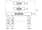
- FIG. 2 is a block diagram showing the configuration of the sound source device in the present embodiment.
- the sound source device 70 includes a signal conversion unit 710, a sound source unit 730, and an output unit 750.
- the sensor 300 is provided corresponding to each key 100, detects a key operation, and outputs a signal corresponding to the detected content. In this example, the sensor 300 outputs a signal according to the key depression amount in three stages. The key pressing speed can be detected according to the interval of this signal.
- the signal conversion unit 710 acquires the output signal of the sensor 300 (sensors 300-1, 300-2,..., 300-88 corresponding to the 88 key 100), and operates according to the operation state of each key 100. Generate and output a signal.
- the operation signal is a MIDI signal. Therefore, the signal conversion unit 710 outputs note-on according to the key pressing operation. At this time, the key number indicating which of the 88 keys 100 has been operated and the velocity corresponding to the key pressing speed are also output in association with the note-on.
- the signal conversion unit 710 outputs the key number and note-off in association with each other.
- a signal corresponding to another operation such as a pedal may be input to the signal conversion unit 710 and reflected in the operation signal.
- the sound source unit 730 generates a sound waveform signal based on the operation signal output from the signal conversion unit 710.
- the output unit 750 outputs the sound waveform signal generated by the sound source unit 730. This sound waveform signal is output to, for example, the speaker 80 or the sound waveform signal output terminal.
- the configuration of the keyboard assembly 10 will be described below.
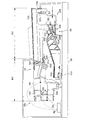
- FIG. 3 is an explanatory diagram when the internal structure of the housing in the present embodiment is viewed from the side of the keyboard.
- the keyboard assembly 10 and the speaker 80 are arranged inside the housing 90. That is, the housing 90 covers at least a part of the keyboard assembly 10 (the connection portion 180 and the frame 500) and the speaker 80.
- the speaker 80 is disposed on the back side of the keyboard assembly 10.
- the speaker 80 is arranged so as to output a sound corresponding to the key depression toward the upper side and the lower side of the housing 90. The sound output downward advances from the lower surface side of the housing 90 to the outside.
- the sound output upward passes through the space inside the keyboard assembly 10 from the inside of the housing 90, and is externally transmitted from the gap between the adjacent keys 100 in the exterior portion PV or the gap between the key 100 and the housing 90.
- the path of sound from the speaker 80 that reaches the space inside the keyboard assembly 10, that is, the space below the key 100 (key body portion) is exemplified as the path SR.
- the keyboard assembly 10 includes a connection unit 180, a hammer assembly 200, and a frame 500 in addition to the key 100 described above.
- the keyboard assembly 10 is a resin-made structure whose most configuration is manufactured by injection molding or the like.
- the frame 500 is fixed to the housing 90.
- the connection unit 180 connects the key 100 so as to be rotatable with respect to the frame 500.
- the connecting portion 180 includes a plate-like flexible member 181, a key-side support portion 183, and a rod-like flexible member 185.
- the plate-like flexible member 181 extends from the rear end of the key 100.
- the key side support portion 183 extends from the rear end of the plate-like flexible member 181.
- a rod-shaped flexible member 185 is supported by the key side support portion 183 and the frame side support portion 585 of the frame 500. That is, a rod-shaped flexible member 185 is disposed between the key 100 and the frame 500. The key 100 can be rotated with respect to the frame 500 by bending the rod-shaped flexible member 185.
- the rod-shaped flexible member 185 is configured to be attachable to and detachable from the key side support portion 183 and the frame side support portion 585.
- the rod-like flexible member 185 may be configured so as not to be attached or detached integrally with the key side support portion 183 and the frame side support portion 585, or by bonding or the like.
- the key 100 includes a front end key guide 151 and a side key guide 153.
- the front end key guide 151 is slidably in contact with the front end frame guide 511 of the frame 500.
- the front end key guide 151 is in contact with the front end frame guide 511 on both sides of the upper and lower scale directions.
- the side key guide 153 is slidably in contact with the side frame guide 513 on both sides in the scale direction.
- the side key guide 153 is disposed in a region corresponding to the non-appearance portion NV on the side surface of the key 100, and exists on the key front end side with respect to the connection portion 180 (plate-like flexible member 181). You may arrange
- the key 100 is connected to the key-side load unit 120 below the exterior portion PV.
- the key-side load portion 120 is connected to the hammer assembly 200 so that the hammer assembly 200 is rotated when the key 100 is rotated.
- the hammer assembly 200 is disposed in a space below the key 100 and is rotatably attached to the frame 500.
- the hammer assembly 200 includes a weight part 230 and a hammer body part 250.
- the hammer main body 250 is provided with a shaft support portion 220 that serves as a bearing for the rotation shaft 520 of the frame 500.
- the shaft support portion 220 and the rotation shaft 520 of the frame 500 are slidably in contact with each other at at least three points.
- the rotation shaft 520 is a shaft that protrudes from the frame 500 in the direction in which the plurality of keys 100 are arranged, that is, the direction D2 in FIG.
- the central axis of the rotation shaft 520 is the central axis when the hammer main body 250 rotates around the rotation shaft 520 while being in contact with the rotation shaft 520 and the shaft support portion 220 (of the hammer main body 250.
- the axis of rotation is the central axis when the hammer main body 250 rotates around the rotation shaft 520 while being in contact with the rotation shaft 520 and the shaft support portion 220 (of the hammer main body 250. The axis of rotation).
- the hammer side load portion 210 is connected to the front end portion of the hammer main body portion 250.
- the hammer side load portion 210 includes a portion that is slidably contacted in the front-rear direction inside the key side load portion 120.
- a lubricant such as grease may be disposed on the contact portion.
- the hammer-side load unit 210 and the key-side load unit 120 (in the following description, these may be collectively referred to as “load generation unit”) generate a part of the load when the key is pressed by sliding on each other. To do.
- the load generating unit is located below the key 100 in the appearance portion PV (frontward from the rear end of the key body).
- the weight portion 230 includes a metal weight, and is connected to the rear end portion of the hammer main body portion 250 (the back side from the rotation shaft). In a normal state (when no key is pressed), the weight portion 230 is placed on the lower stopper 410. As a result, the key 100 is stabilized at the rest position. When the key is depressed, the weight portion 230 moves upward and collides with the upper stopper 430. This defines the end position that is the maximum key depression amount of the key 100. The weight 230 also applies a load to the key press.
- the lower stopper 410 and the upper stopper 430 are formed of a buffer material or the like (nonwoven fabric, elastic body, etc.).
- the sensor 300 is attached to the frame 500 below the load generating unit.
- the hammer-side load portion 210 When the hammer-side load portion 210 is rotated about the rotation shaft 520 by pressing the key and the sensor 300 is crushed, the sensor 300 outputs a detection signal. Therefore, the hammer side load unit 210, the key side load unit 120, and the sensor 300 may be collectively referred to as the pressing device 50. Further, as will be described later, when the switching operation is performed with the electrodes as in the sensor 300, the pressing device 50 can be called a switching device.
- the pressing device 50 is not limited to this configuration. The configuration of the pressing device 50 will be described in detail below.
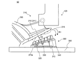
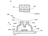
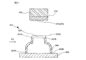
- FIG. 4 is an enlarged cross-sectional view of the pressing device 50 shown in FIG.
- FIG. 5 is a cross-sectional view of the key 100 as viewed from the front end side (D1 direction).
- the hammer side load part 210 has a convex part 270 and a convex part forming surface 215 on which the convex part is formed.
- the convex part 270 is arranged extending on the convex part forming surface 215.
- a plurality of convex portions 270 are provided.
- tip part 270a of the convex part 270 may have roundness.
- the sensor 300 includes an upper electrode 310, a lower electrode 320, an upper electrode support portion 330, a deformation portion 340, and a lower electrode support portion 350.
- the upper electrode 310 is provided on the lower surface 330B of the upper electrode support 330.
- the upper electrode 310 is formed of an elastic body, and a conductive portion is provided at the tip portion 310A.
- molded silicone rubber is used for the upper electrode 310, and conductive carbon black is used for the tip portion 310A as a conductor.
- the lower electrode 320 is disposed on the upper surface side of the lower electrode support portion 350 so as to face the upper electrode 310.
- the lower electrode 320 includes a conductor.
- the lower electrode 320 is made of a metal material such as gold, silver, copper, or platinum, or a conductive resin such as conductive carbon black.
- the deformation part 340 is disposed so as to connect the upper electrode support part 330 and the lower electrode support part 350. Further, the deformable portion 340 may be directly fixed to the lower electrode support portion 350 or indirectly fixed. In this example, the deforming portion 340 is fixed to the lower electrode support portion 350 by the connecting portion 340A and the connecting portion 340B. In addition, when the deformation
- the deformable portion 340 can move the upper electrode 310 and the upper electrode support portion 330 in the vertical direction so that the distance between the upper electrode 310 and the lower electrode 320 can be changed and can be restored to the original position. , Has a function to deform. For this reason, the deformable portion 340 is made of a deformable and recoverable member. For example, molded silicone rubber is used for the deformable portion 340.
- the upper electrode support part 330 is disposed to face the convex part forming surface 215 of the hammer side load part 210.
- the upper surface 330A of the upper electrode support 330 has a flat portion.
- the upper surface 330 ⁇ / b> A may have a recess depending on the shape of the upper electrode 310.
- the upper electrode 310, the upper electrode support part 330, and the deformation part 340 may be collectively referred to as a movable member.
- An elastic body is used for the movable member.
- the upper electrode support portion 330 is made of a soft material such as silicone rubber so that the upper electrode 310 and the deformable portion 340 can be integrally formed with the upper electrode 310 and the deformable portion 340.
- transformation part 340 is not limited to a soft material, A thing like a coil spring may be used.
- the upper electrode support portion 330 may be referred to as an upper surface portion of the movable member.
- the upper electrode support part 330 may be provided with a lubricant.
- the upper electrode support portion 330 is disposed to be inclined with respect to the lower electrode support portion 350 in accordance with the trajectory R ⁇ b> 1 that the hammer side load portion 210 rotates.
- the upper electrode support part 330 should just be set as the structure according to the place arrange
- the lower electrode support part 350 may be provided as another member together with the lower electrode 320.
- the lower electrode support part 350 may be provided as a printed board, and the lower electrode 320 may be an electrode formed on the printed board.
- the lower electrode support part 350 can also be called a support member. That is, the lower electrode 320 and the lower electrode support portion 350 can be collectively referred to as a circuit board.
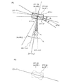
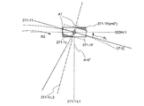
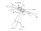
- FIG. 6 shows a rotation of a portion 271-1 (an example of a first portion) that is a part of the convex portion 271 in a plan view of the convex portion forming surface 215 viewed from the upper electrode support portion 330 side (D3 direction in FIG. 4). It is a schematic diagram which shows the relationship with the axis
- FIG. FIG. 7 is an enlarged view of the portion 271-1 near the center point 271-1c.
- FIG. 6 is a schematic diagram for explaining the positional relationship between the convex portion 270 and the rotating shaft 520 by projecting the convex portion 270 and the rotating shaft 520 onto the convex portion forming surface 215 from the D3 direction.
- the D3 direction is a direction perpendicular to the convex portion forming surface 215.
- a line parallel to the line 520H (an example of a parallel line) is perpendicular to the direction in which the rotation shaft 520 extends, and a line passing through the center point 520c of the rotation shaft 520 is a line 520V (vertical line).
- a center point arranged at the same position as the center point 520c of the rotation shaft 520 is defined as a center 271EC, and an arc having a radius r and passing through the center point 271-1c of the portion 271-1 is defined as 271E.
- the portion 271-1 there are three lines starting from the center point 271-1c, namely a line 271-1-L1, a line 271-1-L2, and a line 271-1-L3.
- the line 271-1-L1 is perpendicular to the line 520H, passes through the center point 271-1c, and goes to the line 520H.
- the line 271-1-L2 is a line that is perpendicular to the extending direction of the portion 271-1 and passes through the center point 271-1c toward the line 520H or the line 520V.
- a line 271-1-L3 connects the center point 520c of the rotation shaft 520 and the center point 271-1c of the portion 271-1 and is a line from the center point 271-1c toward the center point 520c.
- the length of the line 271-1-1-L3 is the same as the radius r.
- the center point 520c of the rotation shaft 520 is the center position of the rotation shaft 520 in the direction in which the rotation shaft 520 extends (longitudinal direction of the rotation shaft 520), and the rotation shaft 520 at the center position is the center point 520c. This is the center position in the cross section perpendicular to the extending direction.
- center point 271-1c of the portion 271-1 is the central position of the portion 271-1 in the direction in which the portion 271-1 extends, and is perpendicular to the direction in which the portion 271-1 extends in the central position. It is the center position in the cross section.
- the line 271-1-L1 and the line 271-1-L2 form an angle ⁇ 1. Further, the line 271-1-L1 and the line 271-1-L3 form an angle ⁇ 1.
- the length of the line 271-1-1-L1 is L1.
- the length of the line from the line 520V to the center point 271-1c of the portion 271-1 is D1.
- Equation 1) tan ⁇ 1 D1 / L1
- the angle ⁇ 1 and the angle ⁇ 1 have a relationship of 0 ⁇ 1 ⁇ 2 ⁇ 1.
- a portion of the convex portion 271 that has the same center point 271-1c as the portion 271-1 and is disposed along the arc 271E in the extending direction is defined as a portion 271-1F.
- the portion 271-1 has an angle ⁇ 1 upward (counterclockwise) with respect to the tangent line 271-1T where the portion 271-1F passes through the center point 271-1c in the arc 271E. It can be said that it is tilted downward (counterclockwise) within the range of angle ⁇ 1.
- the portion 271-1 is preferably arranged along the arc 271E in the extending direction. At this time, it is desirable that ⁇ 1 ⁇ 90 °.
- the center point 520c of the rotation shaft 520 overlaps the center 271EC.
- the center point 520c of the rotation shaft 520 may be disposed farther from the arc 271E than the center 271EC, or may be disposed closer to the arc 271E than the center 271EC.
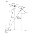
- FIG. 8 is a schematic diagram showing the portion 271-2 (an example of the second portion) which is another portion in addition to the portion 271-1 which is a portion of the convex portion 271, and more specifically.
- the portion 271-2 in the portion 271-2, there are a line 271-2-L1, a line 271-2-L2, and a line 271-2-L3 starting from the center point 271-2c.
- the line 271-2-L1 is a line perpendicular to the line 520H, passing through the center point 271-2c, and going to the line 520H.
- the line 271-2-L2 is a line perpendicular to the extending direction of the portion 271-2 and directed to the line 520H or the line 520V.
- the line 271-2-L2 is the same as the line (line 271-2-L3) connecting the center point 520c of the rotation shaft 520 and the center point 271-2c of the portion 271-2. There may be.
- the line 271-1-L2 and the line 271-1-L3 may be the same. In this case, it can be said that the portion 271-1 and the portion 271-2 are part of an arc centered on the center point 520c of the rotation shaft 520, and the convex portion 271 includes an arc.
- the angle ⁇ 2 formed between the line 271-2-L1 and the line 271-2-L2 is the line 271-1-L1 and the line 271-1 at the center point 271-1c of the portion 271-1.
- the angle ⁇ 1 formed by 1-L2 may be larger.
- the length of the line 271-2-L1 of the portion 271-2 may be shorter than the length of the line 271-1-L1 of the portion 271-1.
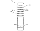
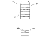
- FIG. 9 is a plan view when the entire convex portion forming surface 215 of the hammer side load portion 210 is viewed from the upper electrode support portion 330 side (D3 direction).
- the plurality of convex portions 270 are arranged in concentric circular arcs with respect to the center point 520 c of the rotation shaft 520. Further, among the convex portions 270, the convex portions 272 are disposed closer to the rotation shaft 520 than the convex portions 271. At this time, the radius of curvature of the convex portion 272 may be smaller than the radius of curvature of the convex portion 271.
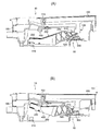
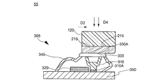
- FIG. 10 is a diagram for explaining the operation of the key assembly when the key (white key) in this embodiment is pressed.
- FIG. 10A is a diagram when the key 100 is in the rest position (a state where the key is not pressed).
- FIG. 10B is a diagram when the key 100 is in the end position (the state where the key is pressed to the end).
- the rod-like flexible member 185 is bent with the center of rotation.
- the rod-shaped flexible member 185 is bent and deformed forward (frontward) of the key 100, but the key 100 moves forward due to the restriction of movement in the front-rear direction by the side key guide 153. Instead, it rotates in the direction perpendicular to the key 100 (D4 direction).
- the key side load portion 120 pushes down the hammer side load portion 210
- the hammer assembly 200 rotates around the rotation shaft 520.
- the hammer side load part 210 functions as one of the actuators.
- the actuator in this case refers to an actuator that operates based on key depression, and the movable member is pressed by the operation to operate the sensor.
- FIG. 11 shows a cross-sectional view of the pressing device 50 viewed from the key tip direction at this time.
- the hammer assembly 200 may vibrate (blur). Further, there may be a slight gap (rattle) between the hammer assembly 200 and the frame 500 to which the hammer assembly 200 is attached.
- the hammer side load portion 210 that is the tip of the hammer assembly 200 is different from the direction in which the hammer side load portion 210 originally rotates about the rotation shaft 520 (for example, the direction in which the keys 100 are arranged (scale direction)). In some cases, the hammer side load portion 210 may move or rotate on the contact surface with the upper electrode support portion 330.
- FIG. 14 is a schematic diagram when the arrangement of the portion 271-1 is changed.
- FIG. 14 shows a portion 371F in which the angle ⁇ 1 in the portion 271-1 is 0, that is, the portion 271-1F is inclined upward (counterclockwise) with respect to the tangent line 271-1T at an angle ⁇ 1 and parallel to the line 520H. This is the case.
- the convex portion 370 is arranged in parallel to the direction of the rotation shaft 520.
- the hammer side load portion 210 rotates around the center point 520c of the rotation shaft 520 on the surface where the convex portion 270 of the hammer side load portion 210 and the upper electrode support portion 330 are in contact with each other.
- the portion 371-1F in the hammer side load portion 210 may bite into the upper electrode support portion 330 formed of a soft material such as silicone rubber.
- friction may occur between the portion 371-1F and the upper electrode support portion 330 when the hammer side load portion 210 rotates in the horizontal direction (R2 direction). In these cases, the area A1 of the portion 371-1F may be caught. For this reason, as shown in FIG.
- the upper electrode support part 330 follows the movement of the hammer side load part 210 in the pressing device 55, and the upper electrode 310 can be electrically connected to the lower electrode 320. Can not. If the upper electrode 310 and the lower electrode 320 cannot be electrically connected, the keyboard device 1 cannot emit sound because the sensor 305 cannot output a detection signal. Further, even if the upper electrode 310 and the lower electrode 320 are partially connected, the keyboard device 1 cannot stably emit a sound because the connection is not stable.
- FIG. 17 shows the case where the angle ⁇ 1 at the portion 271-1 is 2 ⁇ 1 or more, that is, the portion 271-1F is the portion 471-1F inclined at an angle ⁇ 1 or more downward (clockwise) with respect to the tangent line 271-1T. Also in this case, when the hammer side load portion 210 rotates in the horizontal direction (R2 direction), the portion 471-1F bites into the upper electrode support portion 330 as in the case of the portion 371-1F, or the upper electrode support portion 330 and Friction occurs between the two. In these cases, the region A2 of the portion 471-1F may be caught.
- the upper electrode support portion 330 follows the movement of the hammer side load portion 210, and the upper electrode 310 cannot be electrically connected to the lower electrode 320 or does not become a stable connection. Therefore, the keyboard apparatus 1 cannot emit a sound stably.
- the portion 271-1 since the portion 271-1 has 0 ⁇ 1 ⁇ 2 ⁇ 1, the portion 271-1 is supported by the upper electrode when the hammer assembly 200 including the hammer side load portion 210 rotates. It is prevented or reduced from being caught by the part 330. Thereby, it is suppressed that the upper electrode support part 330 follows the movement of the hammer side load part 210. FIG. Therefore, as shown in FIG. 12, when the upper electrode support portion 330 is pushed down by the hammer side load portion 210, the upper electrode 310 and the lower electrode 320 can be reliably in contact with each other. That is, the keyboard device 1 can emit sound stably.
- the deforming portion 340 since the deforming portion 340 operates stably in the above, it is possible to prevent a local force (sometimes referred to as an uneven load) from being applied to the sensor 300, and the durability of the sensor 300 is improved.
- Second Embodiment 2 Configuration of the pressing device 50-1
- a pressing device 50-1 having a structure different from that of the first embodiment will be described.
- the description is used.
- FIG. 13 is a cross-sectional view of the pressing device 50-1 viewed from the key front end side.
- the hammer side load portion 210 and the reaction force generating member 301 have the same configuration as the sensor 300 except for the upper electrode 310 and the lower electrode 320.
- a reaction force generator when no electrode is provided in the pressing device, it may be referred to as a reaction force generator.
- the hammer side load portion 210 and the reaction force generation member 301 have a plurality of tangential planes 333.
- An upper surface 333 A of the tangent plane 333 is in contact with the convex portion 270. Further, the tangent plane 333 includes a rotation fulcrum.
- the reaction force generating member 301 When the hammer-side load portion 210 that functions as an actuator presses the reaction force generating member 301, no component force is generated in the longitudinal direction of the key 100 (direction in which shear stress acts) or the component force is suppressed. For this reason, the hammer side load part 210 always moves perpendicularly (normal direction) with respect to the tangential plane 333 while rotating. Thereby, the reaction force generating member can generate the reaction force at an appropriate timing, and the touch feeling in the keyboard device can be improved. Further, in the above, since the reaction force generating member is prevented from being deformed abnormally, durability is improved.
- the convex portion 270 has an arc
- the convex portion 270 is not partially arc-shaped, and may be parallel to the direction in which the rotation shaft 520 extends. Further, the number and size of the convex portions 270 are not limited. It may be smaller than the convex part 270 shown in FIG. 9, and many may be provided.
- portion 271-1 the example in which the angle ⁇ 1 and the angle ⁇ 1 are 0 ⁇ 1 ⁇ 2 ⁇ 1 and ⁇ 1 ⁇ 90 ° is shown, but the present invention is not limited to this.
- the portion 271-1 may have a portion where 0 ⁇ 1 ⁇ 2 ⁇ 1 and angle ⁇ 1> 90 °.
- the key side load portion 120 may be in direct contact with the upper electrode support portion 330 and pressed.
- the arrangement of the sensor 300 is different from the position shown in FIG. 3, and the sensor 300 is located directly below the key 100 (for example, the middle position of the line connecting the front end key guide 151 and the side key guide 153 in FIG. 3). Be placed.
- the key 100 is connected to the hammer assembly 200 at a location different from the position shown in FIG. Since the key-side load unit 120 is directly affected by the player pressing the key, the upper electrode support unit 330 is more easily displaced in the scale direction. Therefore, the effect by using this indication can be acquired further.
- the hammer side load part 210 and the key side load part 120 do not have to press the upper electrode support part 330.
- the actuator may be an interlocking member that interlocks with a key or a hammer.
- a rotating member such as a lever arranged between a key and a hammer can be used.
Abstract
The purposes of the present invention are: to enable a player to cause a reaction force to be stably generated; and to enable the player to cause sound to be stably emitted. When α1 represents the angle formed between a first line and a second line, and θ1 represents the angle formed between the first line and a third line, the relationship 0<α1<2θ1 is satisfied. The first line is orthogonal to a parallel line passing through the centre point of a rotational shaft, said parallel line being parallel to a direction in which the rotational shaft extends, passes through the centre point of a first portion, and extends towards the parallel line from the centre point of the first portion. The second line is orthogonal to a direction in which the first portion extends at the centre point of the first portion, passes through the centre point of the first portion, and extends towards an orthogonal line orthogonal to the parallel line, said orthogonal line passing through the centre point of the rotational shaft. The third line extends towards the centre point of the rotational shaft from the centre point of the first portion and links the centre point of the rotational shaft and the centre point of the first portion.
Description
本開示は、アクチュエータ、押圧装置および鍵盤装置に関する。
The present disclosure relates to an actuator, a pressing device, and a keyboard device.
アコースティックピアノにおいては、アクション機構の動作により、鍵を通して演奏者の指に所定の感覚(以下、タッチ感という)を与える。アコースティックピアノにおいては、ハンマでの押鍵のためにアクション機構を必要とする。一方、電子鍵盤楽器においては、センサにより押鍵を検出するため、アコースティックピアノのようなアクション機構を有しなくても発音が可能である。アクション機構を用いない電子鍵盤楽器および簡易的なアクション機構を用いた電子鍵盤楽器のタッチ感は、アコースティックピアノのタッチ感に対して大きく変わってしまう。そこで、電子鍵盤楽器において、少しでもアコースティックピアノに近いタッチ感を得るために、アコースティックピアノにおけるハンマに相当する機構を設ける技術が開示されている(例えば、特許文献1)。
In an acoustic piano, a predetermined feeling (hereinafter referred to as touch feeling) is given to a player's finger through a key by the action of an action mechanism. In an acoustic piano, an action mechanism is required for key pressing with a hammer. On the other hand, in an electronic keyboard instrument, a key depression is detected by a sensor, so that sound generation is possible without having an action mechanism such as an acoustic piano. The touch feeling of an electronic keyboard instrument that does not use an action mechanism and an electronic keyboard instrument that uses a simple action mechanism are greatly different from the touch feeling of an acoustic piano. Therefore, a technique for providing a mechanism corresponding to a hammer in an acoustic piano in order to obtain a touch feeling close to that of an acoustic piano in an electronic keyboard instrument has been disclosed (for example, Patent Document 1).
この場合、演奏者の押鍵動作に合わせてハンマが動き、センサが押されることで、音が発せられる。この場合、鍵に対して常に垂直方向に力が加わればよいが、演奏者から遠い位置にある鍵の場合または強く押鍵した場合など、必ずしも垂直方向にのみ力が加わるとは限らず、演奏者から見て鍵に対して横方向にずれて力が加わる場合がある。また、ハンマと、ハンマが取り付けられた部材との間にわずかな隙間などが存在すると、ハンマが鍵の配列された方向(スケール方向という場合がある)に平行に動く、またはハンマが固定された場所を支点としてセンサと接触する面において回動してしまう場合がある。これにより、センサが安定して動作せず、発音不良が生じる恐れがある。また、上記問題はハンマがセンサを押下しない(またはハンマを用いない)鍵盤装置において、鍵が直接センサを押す場合においても発生する恐れがあり、発音不良が生じやすくなる。また、上記問題は、鍵盤装置におけるセンサに限らず、センサを有しない反力(反発力)を必要とする部材においても発生してしまう。
In this case, the hammer moves in accordance with the player's key press operation, and a sound is emitted when the sensor is pressed. In this case, it is sufficient to always apply a force to the key in the vertical direction, but the force is not always applied only in the vertical direction, such as when the key is far away from the performer or when the key is strongly pressed. There is a case in which a force is applied by shifting laterally with respect to the key as viewed from the person. In addition, if there is a slight gap between the hammer and the member to which the hammer is attached, the hammer moves in parallel with the key arrangement direction (sometimes referred to as the scale direction), or the hammer is fixed. In some cases, the surface rotates around the place as a fulcrum. As a result, the sensor does not operate stably, and there is a possibility that sound generation failure may occur. In addition, the above problem may occur even when the key directly presses the sensor in a keyboard device in which the hammer does not press the sensor (or does not use the hammer), and sound generation failure tends to occur. Moreover, the said problem will generate | occur | produce not only in the sensor in a keyboard apparatus but in the member which requires the reaction force (repulsive force) which does not have a sensor.
本開示の目的の一つは、演奏者が安定して反力を発生させられるようにすることにある。また、本開示の目的の一つは、演奏者が安定して音を発せられるようにすることにある。
One of the purposes of the present disclosure is to enable a player to generate a reaction force stably. In addition, one of the objects of the present disclosure is to enable a player to emit a sound stably.
本開示にかかるアクチュエータは、回動軸と、延在して配置された凸部が形成された凸部形成面とを有し、前記凸部形成面の平面視において、前記凸部の第1部分は、前記回動軸の中心点を通り、前記回動軸が延在する方向に平行な平行線と垂直であって、前記第1部分の中心点を通り、前記第1部分の中心点から前記平行線に向かう第1線と、前記第1部分の中心点において前記第1部分が延在する方向に対して垂直であって、前記第1部分の中心点を通り、前記平行線に垂直であって前記回動軸の中心点を通る垂直線に向かう第2線と、がなす角度をα1とし、前記第1線と、前記回動軸の中心点と前記第1部分の中心点とを結ぶ前記第1部分の中心点から前記回動軸の中心点に向かう第3線と、がなす角度をθ1としたときに、0<α1<2θ1の関係を満たすように構成される。
The actuator according to the present disclosure includes a rotation shaft and a convex portion forming surface on which a convex portion arranged to extend is formed, and the first portion of the convex portion in the plan view of the convex portion forming surface. The portion passes through the center point of the pivot shaft, is perpendicular to a parallel line parallel to the direction in which the pivot shaft extends, passes through the center point of the first portion, and passes through the center point of the first portion. A first line from the first part toward the parallel line and a direction perpendicular to the direction in which the first part extends at the central point of the first part, and passes through the central point of the first part to the parallel line An angle formed by a second line that is perpendicular and passes through a vertical line passing through the center point of the rotation axis is α1, and the first line, the center point of the rotation axis, and the center point of the first part 0 <α1 <2 where θ1 is the angle formed by the third line from the center point of the first portion connecting to the center point of the rotation axis It is configured to satisfy the relationship of θ1.
上記アクチュエータにおいて、角度α1は、α1<90°であってもよい。
In the actuator, the angle α1 may be α1 <90 °.
上記アクチュエータにおいて、前記凸部は、さらに第2部分を有し、前記平行線と垂直であって、前記第2部分の中心点を通り、前記第2部分の中心点から前記平行線に向かう第4線と、前記第2部分が延在する方向に対して垂直であって、前記第2部分の中心点を通り、前記平行線または前記垂直線に向かう第5線とがなす角度α2は、前記角度α1よりも大きくてもよい。
In the actuator, the convex portion further includes a second portion, is perpendicular to the parallel line, passes through a central point of the second portion, and extends from the central point of the second portion toward the parallel line. The angle α2 formed by the four lines and the fifth line that is perpendicular to the direction in which the second portion extends and passes through the center point of the second portion and toward the parallel line or the vertical line is: It may be larger than the angle α1.
上記アクチュエータにおいて、凸部は、回動軸の中心点に対して円弧状に配置されてもよい。
In the actuator, the convex portion may be arranged in an arc shape with respect to the center point of the rotation axis.
上記アクチュエータにおいて、前記凸部は、複数設けられ、前記複数の凸部のうちの1つである第1凸部は、前記複数の凸部のうちの前記第1凸部以外の1つである第2凸部よりも前記回動軸の近くに配置され、前記第1凸部の曲率半径は、前記第2凸部の曲率半径よりも小さくてもよい。
In the actuator, a plurality of the convex portions are provided, and a first convex portion that is one of the plurality of convex portions is one other than the first convex portion among the plurality of convex portions. The first convex portion may be disposed closer to the rotation axis than the second convex portion, and the curvature radius of the first convex portion may be smaller than the curvature radius of the second convex portion.
前記アクチュエータは、回動中心と、円弧を含む凸部が形成された凸部形成面を有してもよい。
The actuator may have a rotation center and a projection forming surface on which a projection including an arc is formed.
上記アクチュエータにおいて、円弧の中心は、回動中心と同じ位置に配置されてもよい。
In the actuator, the center of the arc may be arranged at the same position as the rotation center.
本開示の別の観点に係る押圧装置は、上記アクチュエータと、前記アクチュエータにより押圧される可動部材と、を有し、可動部材は、弾性材を含む。
A pressing device according to another aspect of the present disclosure includes the actuator and a movable member pressed by the actuator, and the movable member includes an elastic material.
上記押圧装置は、反力発生装置であってもよい。
The pressure device may be a reaction force generator.
上記押圧装置は、スイッチング装置であってもよい。
The switching device may be a switching device.
本開示にかかる鍵盤装置は、上記押圧装置を有し、前記アクチュエータは、ハンマである。
The keyboard device according to the present disclosure includes the pressing device, and the actuator is a hammer.
本開示の別の観点にかかる鍵盤装置は、上記押圧装置を有し、前記アクチュエータは、鍵である。
A keyboard device according to another aspect of the present disclosure includes the pressing device, and the actuator is a key.
本開示の別の観点にかかる鍵盤装置は、上記押圧装置を有し、前記アクチュエータは、鍵またはハンマと連動する連動部材である。
A keyboard device according to another aspect of the present disclosure includes the pressing device, and the actuator is an interlocking member that interlocks with a key or a hammer.
本開示によれば、演奏者が安定して反力を発生させることができる。また、本開示によれば、演奏者が安定して音を発することできる。
According to the present disclosure, the performer can stably generate a reaction force. Moreover, according to this indication, a player can emit a sound stably.
以下、本開示の一実施形態における鍵盤装置について、図面を参照しながら詳細に説明する。以下に示す実施形態は本開示の実施形態の一例であって、本開示はこれらの実施形態に限定して解釈されるものではない。なお、本実施形態で参照する図面において、同一部分または同様な機能を有する部分には同一の符号または類似の符号(数字の後ろに、AまたはBなどの文字を付す場合がある)を付し、その繰り返しの説明は省略する場合がある。また、図面の寸法比率(各構成間の比率、縦横高さ方向の比率等)は説明の都合上実際の比率とは異なったり、構成の一部が図面から省略されたりする場合がある。
Hereinafter, a keyboard device according to an embodiment of the present disclosure will be described in detail with reference to the drawings. The following embodiments are examples of embodiments of the present disclosure, and the present disclosure is not construed as being limited to these embodiments. Note that in the drawings referred to in this embodiment, the same portions or portions having similar functions are denoted by the same reference symbols or similar symbols (a letter such as A or B may be appended to the number). The repeated description may be omitted. In addition, the dimensional ratios of the drawings (the ratios between the components, the ratios in the vertical and horizontal height directions, etc.) may be different from the actual ratios for convenience of explanation, or some of the configurations may be omitted from the drawings.
<第1実施形態>
(1-1.鍵盤装置の構成)
図1は、本実施形態における鍵盤装置の構成を示す図である。鍵盤装置1は、この例では、電子ピアノなどユーザ(演奏者)の押鍵に応じて発音する電子鍵盤楽器である。なお、鍵盤装置1は、外部の音源装置を制御するための制御データ(例えば、MIDI)を、押鍵に応じて出力する鍵盤型のコントローラであってもよい。この場合には、鍵盤装置1は、音源装置を備えていなくてもよい。 <First Embodiment>
(1-1. Configuration of keyboard device)
FIG. 1 is a diagram illustrating a configuration of a keyboard device according to the present embodiment. In this example, thekeyboard device 1 is an electronic keyboard instrument that emits sound in response to a user (player) key depression such as an electronic piano. Note that the keyboard device 1 may be a keyboard-type controller that outputs control data (for example, MIDI) for controlling an external sound source device in response to a key depression. In this case, the keyboard device 1 may not include the sound source device.
(1-1.鍵盤装置の構成)
図1は、本実施形態における鍵盤装置の構成を示す図である。鍵盤装置1は、この例では、電子ピアノなどユーザ(演奏者)の押鍵に応じて発音する電子鍵盤楽器である。なお、鍵盤装置1は、外部の音源装置を制御するための制御データ(例えば、MIDI)を、押鍵に応じて出力する鍵盤型のコントローラであってもよい。この場合には、鍵盤装置1は、音源装置を備えていなくてもよい。 <First Embodiment>
(1-1. Configuration of keyboard device)
FIG. 1 is a diagram illustrating a configuration of a keyboard device according to the present embodiment. In this example, the
鍵盤装置1は、鍵盤アセンブリ10を備える。鍵盤アセンブリ10は、白鍵100wおよび黒鍵100bを含む。複数の白鍵100wと黒鍵100bとが並んで配列されている。鍵100の数は、N個であり、この例では88個である。この配列された方向をスケール方向という。白鍵100wおよび黒鍵100bを特に区別せずに説明できる場合には、鍵100という場合がある。以下の説明においても、符号の最後に「w」を付した場合には、白鍵に対応する構成であることを意味している。また、符号の最後に「b」を付した場合には、黒鍵に対応する構成であることを意味している。
The keyboard device 1 includes a keyboard assembly 10. The keyboard assembly 10 includes a white key 100w and a black key 100b. A plurality of white keys 100w and black keys 100b are arranged side by side. The number of keys 100 is N, which is 88 in this example. This arranged direction is called a scale direction. When the white key 100w and the black key 100b can be described without particular distinction, the key 100 may be referred to. Also in the following description, when “w” is added to the end of the reference sign, it means that the configuration corresponds to the white key. Further, when “b” is added at the end of the code, it means that the configuration corresponds to the black key.
鍵盤アセンブリ10の一部は、筐体90の内部に存在している。鍵盤装置1を上方から見た場合において、鍵盤アセンブリ10のうち筐体90に覆われている部分を非外観部NVといい、筐体90から露出してユーザから視認できる部分を外観部PVという。すなわち、外観部PVは、鍵100の一部であって、ユーザによって演奏操作が可能な領域を示す。以下、鍵100のうち外観部PVによって露出されている部分を鍵本体部という場合がある。
A part of the keyboard assembly 10 exists inside the housing 90. When the keyboard device 1 is viewed from above, a portion of the keyboard assembly 10 covered by the casing 90 is referred to as a non-appearance portion NV, and a portion exposed from the casing 90 and visible to the user is referred to as an appearance portion PV. . That is, the appearance part PV is a part of the key 100 and indicates an area where the user can perform a performance operation. Hereinafter, a portion of the key 100 that is exposed by the appearance portion PV may be referred to as a key body portion.
筐体90内部には、音源装置70およびスピーカ80が配置されている。音源装置70は、鍵100の押下に伴って音波形信号を生成する。スピーカ80は、音源装置70において生成された音波形信号を外部の空間に出力する。なお、鍵盤装置1は、音量をコントロールするためのスライダ、音色を切り替えるためのスイッチ、様々な情報を表示するディスプレイなどが備えられていてもよい。
Inside the housing 90, a sound source device 70 and a speaker 80 are arranged. The tone generator 70 generates a sound waveform signal when the key 100 is pressed. The speaker 80 outputs the sound waveform signal generated in the sound source device 70 to an external space. The keyboard device 1 may be provided with a slider for controlling the volume, a switch for switching timbres, a display for displaying various information, and the like.
なお、本明細書における説明において、上、下、左、右、手前および奥などの方向は、演奏するときの演奏者から鍵盤装置1を見た場合の方向を示している。そのため、例えば、非外観部NVは、外観部PVよりも奥側に位置している、と表現することができる。また、鍵前端側(鍵前方側)、鍵後端側(鍵後方側)のように、鍵100を基準として方向を示す場合もある。この場合、鍵前端側は鍵100に対して演奏者から見た手前側を示す。鍵後端側は鍵100に対して演奏者から見た奥側を示す。この定義によれば、黒鍵100bのうち、黒鍵100bの鍵本体部の前端から後端までが、白鍵100wよりも上方に突出した部分である、と表現することができる。なお、図1における方向D1は、前方から後方に向かう方向であり、前後方向D1ということができる。また、方向D2は、複数の鍵100が配列される方向(スケール方向)であり、図1においては、左右方向D2ということができる。
In the description of the present specification, directions such as up, down, left, right, front, and back indicate directions when the keyboard device 1 is viewed from the performer when performing. Therefore, for example, the non-appearance part NV can be expressed as being located on the back side with respect to the appearance part PV. Further, the direction may be indicated with the key 100 as a reference, such as the front end side (key front side) and the rear end side (key rear side). In this case, the key front end side indicates the front side as viewed from the performer with respect to the key 100. The rear end side of the key indicates the back side viewed from the performer with respect to the key 100. According to this definition, the black key 100b can be expressed as a portion protruding upward from the white key 100w from the front end to the rear end of the key body of the black key 100b. Note that a direction D1 in FIG. 1 is a direction from the front to the rear, and can be referred to as the front-rear direction D1. The direction D2 is a direction (scale direction) in which a plurality of keys 100 are arranged, and can be referred to as a left-right direction D2 in FIG.
図2は、本実施形態における音源装置の構成を示すブロック図である。音源装置70は、信号変換部710、音源部730および出力部750を備える。センサ300は、各鍵100に対応して設けられ、鍵の操作を検出し、検出した内容に応じた信号を出力する。この例では、センサ300は、3段階の押鍵量に応じて信号を出力する。この信号の間隔に応じて押鍵速度が検出可能である。
FIG. 2 is a block diagram showing the configuration of the sound source device in the present embodiment. The sound source device 70 includes a signal conversion unit 710, a sound source unit 730, and an output unit 750. The sensor 300 is provided corresponding to each key 100, detects a key operation, and outputs a signal corresponding to the detected content. In this example, the sensor 300 outputs a signal according to the key depression amount in three stages. The key pressing speed can be detected according to the interval of this signal.
信号変換部710は、センサ300(88の鍵100に対応したセンサ300-1、300-2、・・・、300-88)の出力信号を取得し、各鍵100における操作状態に応じた操作信号を生成して出力する。この例では、操作信号はMIDI形式の信号である。そのため、押鍵操作に応じて、信号変換部710はノートオンを出力する。このとき、88個の鍵100のいずれが操作されたかを示すキーナンバ、および押鍵速度に対応するベロシティについてもノートオンに対応付けて出力される。一方、離鍵操作に応じて、信号変換部710はキーナンバとノートオフとを対応付けて出力する。信号変換部710には、ペダル等の他の操作に応じた信号が入力され、操作信号に反映されてもよい。
The signal conversion unit 710 acquires the output signal of the sensor 300 (sensors 300-1, 300-2,..., 300-88 corresponding to the 88 key 100), and operates according to the operation state of each key 100. Generate and output a signal. In this example, the operation signal is a MIDI signal. Therefore, the signal conversion unit 710 outputs note-on according to the key pressing operation. At this time, the key number indicating which of the 88 keys 100 has been operated and the velocity corresponding to the key pressing speed are also output in association with the note-on. On the other hand, in response to the key release operation, the signal conversion unit 710 outputs the key number and note-off in association with each other. A signal corresponding to another operation such as a pedal may be input to the signal conversion unit 710 and reflected in the operation signal.
音源部730は、信号変換部710から出力された操作信号に基づいて、音波形信号を生成する。出力部750は、音源部730によって生成された音波形信号を出力する。この音波形信号は、例えば、スピーカ80または音波形信号出力端子などに出力される。鍵盤アセンブリ10の構成について、以下において説明する。
The sound source unit 730 generates a sound waveform signal based on the operation signal output from the signal conversion unit 710. The output unit 750 outputs the sound waveform signal generated by the sound source unit 730. This sound waveform signal is output to, for example, the speaker 80 or the sound waveform signal output terminal. The configuration of the keyboard assembly 10 will be described below.
(1-2.鍵盤アセンブリの構成)
図3は、本実施形態における筐体内部の構成を鍵盤側面方向から見た場合の説明図である。図3に示すように、筐体90の内部において、鍵盤アセンブリ10およびスピーカ80が配置されている。すなわち、筐体90は、少なくとも、鍵盤アセンブリ10の一部(接続部180およびフレーム500)およびスピーカ80を覆っている。スピーカ80は、鍵盤アセンブリ10の奥側に配置されている。このスピーカ80は、押鍵に応じた音を筐体90の上方および下方に向けて出力するように配置されている。下方に出力される音は、筐体90の下面側から外部に進む。一方、上方に出力される音は筐体90の内部から鍵盤アセンブリ10の内部の空間を通過して、外観部PVにおける鍵100の隣接間の隙間または鍵100と筐体90との隙間から外部に進む。なお、鍵盤アセンブリ10の内部の空間、すなわち鍵100(鍵本体部)の下方側の空間に到達する、スピーカ80からの音の経路は、経路SRとして例示されている。 (1-2. Configuration of keyboard assembly)
FIG. 3 is an explanatory diagram when the internal structure of the housing in the present embodiment is viewed from the side of the keyboard. As shown in FIG. 3, thekeyboard assembly 10 and the speaker 80 are arranged inside the housing 90. That is, the housing 90 covers at least a part of the keyboard assembly 10 (the connection portion 180 and the frame 500) and the speaker 80. The speaker 80 is disposed on the back side of the keyboard assembly 10. The speaker 80 is arranged so as to output a sound corresponding to the key depression toward the upper side and the lower side of the housing 90. The sound output downward advances from the lower surface side of the housing 90 to the outside. On the other hand, the sound output upward passes through the space inside the keyboard assembly 10 from the inside of the housing 90, and is externally transmitted from the gap between the adjacent keys 100 in the exterior portion PV or the gap between the key 100 and the housing 90. Proceed to Note that the path of sound from the speaker 80 that reaches the space inside the keyboard assembly 10, that is, the space below the key 100 (key body portion), is exemplified as the path SR.
図3は、本実施形態における筐体内部の構成を鍵盤側面方向から見た場合の説明図である。図3に示すように、筐体90の内部において、鍵盤アセンブリ10およびスピーカ80が配置されている。すなわち、筐体90は、少なくとも、鍵盤アセンブリ10の一部(接続部180およびフレーム500)およびスピーカ80を覆っている。スピーカ80は、鍵盤アセンブリ10の奥側に配置されている。このスピーカ80は、押鍵に応じた音を筐体90の上方および下方に向けて出力するように配置されている。下方に出力される音は、筐体90の下面側から外部に進む。一方、上方に出力される音は筐体90の内部から鍵盤アセンブリ10の内部の空間を通過して、外観部PVにおける鍵100の隣接間の隙間または鍵100と筐体90との隙間から外部に進む。なお、鍵盤アセンブリ10の内部の空間、すなわち鍵100(鍵本体部)の下方側の空間に到達する、スピーカ80からの音の経路は、経路SRとして例示されている。 (1-2. Configuration of keyboard assembly)
FIG. 3 is an explanatory diagram when the internal structure of the housing in the present embodiment is viewed from the side of the keyboard. As shown in FIG. 3, the
鍵盤アセンブリ10は、上述した鍵100の他にも、接続部180、ハンマアセンブリ200およびフレーム500を含む。鍵盤アセンブリ10は、ほとんどの構成が射出成形などによって製造された樹脂製の構造体である。フレーム500は、筐体90に固定されている。接続部180は、フレーム500に対して回動可能に鍵100を接続する。接続部180は、板状可撓性部材181、鍵側支持部183および棒状可撓性部材185を備える。板状可撓性部材181は、鍵100の後端から延在している。鍵側支持部183は、板状可撓性部材181の後端から延在している。棒状可撓性部材185が、鍵側支持部183およびフレーム500のフレーム側支持部585によって支持されている。すなわち、鍵100とフレーム500との間に、棒状可撓性部材185が配置されている。棒状可撓性部材185が曲がることによって、鍵100がフレーム500に対して回動することができる。棒状可撓性部材185は、鍵側支持部183とフレーム側支持部585とに対して、着脱可能に構成されている。なお、棒状可撓性部材185は、鍵側支持部183とフレーム側支持部585と一体となって、または接着等により、着脱できない構成であってもよい。
The keyboard assembly 10 includes a connection unit 180, a hammer assembly 200, and a frame 500 in addition to the key 100 described above. The keyboard assembly 10 is a resin-made structure whose most configuration is manufactured by injection molding or the like. The frame 500 is fixed to the housing 90. The connection unit 180 connects the key 100 so as to be rotatable with respect to the frame 500. The connecting portion 180 includes a plate-like flexible member 181, a key-side support portion 183, and a rod-like flexible member 185. The plate-like flexible member 181 extends from the rear end of the key 100. The key side support portion 183 extends from the rear end of the plate-like flexible member 181. A rod-shaped flexible member 185 is supported by the key side support portion 183 and the frame side support portion 585 of the frame 500. That is, a rod-shaped flexible member 185 is disposed between the key 100 and the frame 500. The key 100 can be rotated with respect to the frame 500 by bending the rod-shaped flexible member 185. The rod-shaped flexible member 185 is configured to be attachable to and detachable from the key side support portion 183 and the frame side support portion 585. The rod-like flexible member 185 may be configured so as not to be attached or detached integrally with the key side support portion 183 and the frame side support portion 585, or by bonding or the like.
鍵100は、前端鍵ガイド151および側面鍵ガイド153を備える。前端鍵ガイド151は、フレーム500の前端フレームガイド511を覆った状態で摺動可能に接触している。前端鍵ガイド151は、その上部と下部のスケール方向の両側において、前端フレームガイド511と接触している。側面鍵ガイド153は、スケール方向の両側において側面フレームガイド513と摺動可能に接触している。この例では、側面鍵ガイド153は、鍵100の側面のうち非外観部NVに対応する領域に配置され、接続部180(板状可撓性部材181)よりも鍵前端側に存在するが、外観部PVに対応する領域に配置されてもよい。
The key 100 includes a front end key guide 151 and a side key guide 153. The front end key guide 151 is slidably in contact with the front end frame guide 511 of the frame 500. The front end key guide 151 is in contact with the front end frame guide 511 on both sides of the upper and lower scale directions. The side key guide 153 is slidably in contact with the side frame guide 513 on both sides in the scale direction. In this example, the side key guide 153 is disposed in a region corresponding to the non-appearance portion NV on the side surface of the key 100, and exists on the key front end side with respect to the connection portion 180 (plate-like flexible member 181). You may arrange | position to the area | region corresponding to the external appearance part PV.
また、鍵100は、外観部PVの下方において鍵側負荷部120が接続されている。鍵側負荷部120は、鍵100が回動するときに、ハンマアセンブリ200を回動させるように、ハンマアセンブリ200に接続される。
Also, the key 100 is connected to the key-side load unit 120 below the exterior portion PV. The key-side load portion 120 is connected to the hammer assembly 200 so that the hammer assembly 200 is rotated when the key 100 is rotated.
ハンマアセンブリ200は、鍵100の下方側の空間に配置され、フレーム500に対して回動可能に取り付けられている。ハンマアセンブリ200は、錘部230およびハンマ本体部250を備える。ハンマ本体部250には、フレーム500の回動軸520の軸受となる軸支持部220が配置されている。軸支持部220とフレーム500の回動軸520とは少なくとも3点で摺動可能に接触する。なお、回動軸520は、フレーム500から、複数の鍵100が配列される方向、つまり図1の方向D2に突出するシャフトである。従って、回動軸520の中心軸は、ハンマ本体部250が回動軸520と軸支持部220で接触しつつ、回動軸520の周りに回動するときの中心軸(ハンマ本体部250の回動の中心となる軸)となる。
The hammer assembly 200 is disposed in a space below the key 100 and is rotatably attached to the frame 500. The hammer assembly 200 includes a weight part 230 and a hammer body part 250. The hammer main body 250 is provided with a shaft support portion 220 that serves as a bearing for the rotation shaft 520 of the frame 500. The shaft support portion 220 and the rotation shaft 520 of the frame 500 are slidably in contact with each other at at least three points. The rotation shaft 520 is a shaft that protrudes from the frame 500 in the direction in which the plurality of keys 100 are arranged, that is, the direction D2 in FIG. Therefore, the central axis of the rotation shaft 520 is the central axis when the hammer main body 250 rotates around the rotation shaft 520 while being in contact with the rotation shaft 520 and the shaft support portion 220 (of the hammer main body 250. The axis of rotation).
ハンマ側負荷部210は、ハンマ本体部250の前端部に接続されている。ハンマ側負荷部210は、鍵側負荷部120の内部において概ね前後方向に摺動可能に接触する部分を備える。この接触部分にはグリース等の潤滑材が配置されていてもよい。ハンマ側負荷部210および鍵側負荷部120(以下の説明において、これらをまとめて「負荷発生部」という場合がある)とは、互いに摺動することで押鍵時の負荷の一部を発生する。負荷発生部は、この例では外観部PV(鍵本体部の後端よりも前方)における鍵100の下方に位置する。
The hammer side load portion 210 is connected to the front end portion of the hammer main body portion 250. The hammer side load portion 210 includes a portion that is slidably contacted in the front-rear direction inside the key side load portion 120. A lubricant such as grease may be disposed on the contact portion. The hammer-side load unit 210 and the key-side load unit 120 (in the following description, these may be collectively referred to as “load generation unit”) generate a part of the load when the key is pressed by sliding on each other. To do. In this example, the load generating unit is located below the key 100 in the appearance portion PV (frontward from the rear end of the key body).
錘部230は、金属製の錘を含み、ハンマ本体部250の後端部(回動軸よりも奥側)に接続されている。通常時(押鍵していないとき)には、錘部230が下側ストッパ410に載置された状態になる。これによって、鍵100はレスト位置で安定する。押鍵されると、錘部230が上方に移動し、上側ストッパ430に衝突する。これによって鍵100の最大押鍵量となるエンド位置が規定される。この錘部230によっても、押鍵に対して負荷を与える。下側ストッパ410および上側ストッパ430は、緩衝材等(不織布、弾性体等)で形成されている。
The weight portion 230 includes a metal weight, and is connected to the rear end portion of the hammer main body portion 250 (the back side from the rotation shaft). In a normal state (when no key is pressed), the weight portion 230 is placed on the lower stopper 410. As a result, the key 100 is stabilized at the rest position. When the key is depressed, the weight portion 230 moves upward and collides with the upper stopper 430. This defines the end position that is the maximum key depression amount of the key 100. The weight 230 also applies a load to the key press. The lower stopper 410 and the upper stopper 430 are formed of a buffer material or the like (nonwoven fabric, elastic body, etc.).
負荷発生部の下方において、フレーム500にセンサ300が取り付けられている。押鍵により回動軸520を中心としてハンマ側負荷部210が回動してセンサ300が押しつぶされると、センサ300は検出信号を出力する。したがって、ハンマ側負荷部210、鍵側負荷部120およびセンサ300を合わせて押圧装置50という場合がある。また、後述するように、センサ300のように電極を有してスイッチング動作を行う場合、押圧装置50は、スイッチング装置ということができる。なお、押圧装置50は、この構成に限定されない。押圧装置50の構成について以下に詳述する。
The sensor 300 is attached to the frame 500 below the load generating unit. When the hammer-side load portion 210 is rotated about the rotation shaft 520 by pressing the key and the sensor 300 is crushed, the sensor 300 outputs a detection signal. Therefore, the hammer side load unit 210, the key side load unit 120, and the sensor 300 may be collectively referred to as the pressing device 50. Further, as will be described later, when the switching operation is performed with the electrodes as in the sensor 300, the pressing device 50 can be called a switching device. The pressing device 50 is not limited to this configuration. The configuration of the pressing device 50 will be described in detail below.
(1-3.押圧装置の構成)
図4は、図3の押圧装置50を抜粋して拡大した断面図である。図5は、鍵100の前端側(D1方向)から見た断面図である。 (1-3. Configuration of pressing device)
FIG. 4 is an enlarged cross-sectional view of thepressing device 50 shown in FIG. FIG. 5 is a cross-sectional view of the key 100 as viewed from the front end side (D1 direction).
図4は、図3の押圧装置50を抜粋して拡大した断面図である。図5は、鍵100の前端側(D1方向)から見た断面図である。 (1-3. Configuration of pressing device)
FIG. 4 is an enlarged cross-sectional view of the
ハンマ側負荷部210は、凸部270と、凸部が形成された凸部形成面215とを有する。凸部270は、凸部形成面215に延在して配置される。また、この例では、凸部270が、複数設けられている。なお、凸部270の先端部270aは、丸みを有してもよい。
The hammer side load part 210 has a convex part 270 and a convex part forming surface 215 on which the convex part is formed. The convex part 270 is arranged extending on the convex part forming surface 215. In this example, a plurality of convex portions 270 are provided. In addition, the front-end | tip part 270a of the convex part 270 may have roundness.
センサ300は、上部電極310、下部電極320、上部電極支持部330、変形部340および下部電極支持部350を備える。
The sensor 300 includes an upper electrode 310, a lower electrode 320, an upper electrode support portion 330, a deformation portion 340, and a lower electrode support portion 350.
上部電極310は、上部電極支持部330の下面330Bに設けられる。上部電極310は、弾性体で形成され、先端部310Aに導電部が設けられる。この例では、上部電極310には、成型加工されたシリコーンゴムが用いられ、先端部310Aには導電体として導電性カーボンブラックが用いられる。
The upper electrode 310 is provided on the lower surface 330B of the upper electrode support 330. The upper electrode 310 is formed of an elastic body, and a conductive portion is provided at the tip portion 310A. In this example, molded silicone rubber is used for the upper electrode 310, and conductive carbon black is used for the tip portion 310A as a conductor.
下部電極320は、上部電極310に対向するように、下部電極支持部350の上面側に配置される。下部電極320は、導電体を含む。例えば、下部電極320には、金、銀、銅、白金などの金属材料、または導電性のカーボンブラックなどの導電樹脂が用いられる。
The lower electrode 320 is disposed on the upper surface side of the lower electrode support portion 350 so as to face the upper electrode 310. The lower electrode 320 includes a conductor. For example, the lower electrode 320 is made of a metal material such as gold, silver, copper, or platinum, or a conductive resin such as conductive carbon black.
変形部340は、上部電極支持部330と、下部電極支持部350とを結ぶように配置される。また、変形部340は、下部電極支持部350と直接固定されてもよいし、間接的に固定されてもよい。この例では、変形部340は、接続部340Aおよび接続部340Bで下部電極支持部350と固定されている。なお、変形部340が他の部材に固定されている場合は、下部電極支持部350と固定されなくてもよい。変形部340は、上部電極310および上部電極支持部330を上下方向に移動可能とすることにより、上部電極310と下部電極320との距離を可変にし、かつ元の位置に復元可能となるように、変形する機能を有する。そのため、変形部340は、変形可能でかつ復元可能な部材が用いられる。例えば、変形部340には、成形加工されたシリコーンゴムが用いられる。
The deformation part 340 is disposed so as to connect the upper electrode support part 330 and the lower electrode support part 350. Further, the deformable portion 340 may be directly fixed to the lower electrode support portion 350 or indirectly fixed. In this example, the deforming portion 340 is fixed to the lower electrode support portion 350 by the connecting portion 340A and the connecting portion 340B. In addition, when the deformation | transformation part 340 is being fixed to the other member, it does not need to be fixed with the lower electrode support part 350. FIG. The deformable portion 340 can move the upper electrode 310 and the upper electrode support portion 330 in the vertical direction so that the distance between the upper electrode 310 and the lower electrode 320 can be changed and can be restored to the original position. , Has a function to deform. For this reason, the deformable portion 340 is made of a deformable and recoverable member. For example, molded silicone rubber is used for the deformable portion 340.
上部電極支持部330は、ハンマ側負荷部210のうち凸部形成面215に対向して配置される。図5において、上部電極支持部330の上面330Aは、平坦な部分を有する。なお、上面330Aは、上部電極310の形状に応じて、凹みを有しても良い。上部電極310、上部電極支持部330および変形部340を合わせて可動部材という場合がある。可動部材には、弾性体が用いられる。例えば、上部電極支持部330には、上部電極310および変形部340と一体で加工成形できるように、シリコーンゴムなどの軟質材料が用いられる。なお、上部電極支持部330、上部電極310または変形部340は、軟質材料に限定されず、コイルバネのようなものが用いられてもよい。可動部材とした場合、上部電極支持部330は、可動部材の上面部という場合がある。また、上部電極支持部330には、潤滑材が設けられてもよい。また、図3に示すように、上部電極支持部330は、ハンマ側負荷部210の回動する軌道R1に合わせて下側電極支持部350に対して傾斜して配置されている。なお、上部電極支持部330は、配置される場所に応じた構成とすればよく、必ずしも傾斜して配置されなくてもよい。
The upper electrode support part 330 is disposed to face the convex part forming surface 215 of the hammer side load part 210. In FIG. 5, the upper surface 330A of the upper electrode support 330 has a flat portion. Note that the upper surface 330 </ b> A may have a recess depending on the shape of the upper electrode 310. The upper electrode 310, the upper electrode support part 330, and the deformation part 340 may be collectively referred to as a movable member. An elastic body is used for the movable member. For example, the upper electrode support portion 330 is made of a soft material such as silicone rubber so that the upper electrode 310 and the deformable portion 340 can be integrally formed with the upper electrode 310 and the deformable portion 340. In addition, the upper electrode support part 330, the upper electrode 310, or the deformation | transformation part 340 is not limited to a soft material, A thing like a coil spring may be used. When a movable member is used, the upper electrode support portion 330 may be referred to as an upper surface portion of the movable member. Further, the upper electrode support part 330 may be provided with a lubricant. Further, as shown in FIG. 3, the upper electrode support portion 330 is disposed to be inclined with respect to the lower electrode support portion 350 in accordance with the trajectory R <b> 1 that the hammer side load portion 210 rotates. In addition, the upper electrode support part 330 should just be set as the structure according to the place arrange | positioned, and does not necessarily need to be inclined and arrange | positioned.
下部電極支持部350は、下部電極320とともに、別の部材として設けられてもよい。たとえば、下部電極支持部350は、プリント基板として設けられ、下部電極320は、プリント基板上に形成された電極とすることができる。下部電極支持部350は、支持部材ということもできる。つまり、下部電極320および下部電極支持部350を合わせて、回路基板ということができる。
The lower electrode support part 350 may be provided as another member together with the lower electrode 320. For example, the lower electrode support part 350 may be provided as a printed board, and the lower electrode 320 may be an electrode formed on the printed board. The lower electrode support part 350 can also be called a support member. That is, the lower electrode 320 and the lower electrode support portion 350 can be collectively referred to as a circuit board.
(1-4.凸部の構成)
次に、複数設けられた凸部270のうち一の凸部271について説明する。図6は、上部電極支持部330側(図4のD3方向)から見た凸部形成面215の平面視において凸部271の一部分である部分271-1(第1部分の一例)と回動軸520との関係を示す模式図である。また、図7は、部分271-1の中心点271-1c付近の拡大図である。なお、図6、図7(A)、図7(B)、図8、図14及び図17は、凸部形成面215をD3方向から平面視したときに、凸部形成面215を投影面として、D3方向から凸部270及び回動軸520を凸部形成面215に投影させて、凸部270と回動軸520の配置関係を説明するための模式図である。なお、D3方向は、凸部形成面215に垂直な方向である。 (1-4. Configuration of convex portion)
Next, oneconvex portion 271 among the plurality of convex portions 270 will be described. FIG. 6 shows a rotation of a portion 271-1 (an example of a first portion) that is a part of the convex portion 271 in a plan view of the convex portion forming surface 215 viewed from the upper electrode support portion 330 side (D3 direction in FIG. 4). It is a schematic diagram which shows the relationship with the axis | shaft 520. FIG. FIG. 7 is an enlarged view of the portion 271-1 near the center point 271-1c. 6, 7 </ b> A, 7 </ b> B, 8, 14, and 17, the projection forming surface 215 is a projection plane when the projection forming surface 215 is viewed in plan from the direction D <b> 3. FIG. 6 is a schematic diagram for explaining the positional relationship between the convex portion 270 and the rotating shaft 520 by projecting the convex portion 270 and the rotating shaft 520 onto the convex portion forming surface 215 from the D3 direction. The D3 direction is a direction perpendicular to the convex portion forming surface 215.
次に、複数設けられた凸部270のうち一の凸部271について説明する。図6は、上部電極支持部330側(図4のD3方向)から見た凸部形成面215の平面視において凸部271の一部分である部分271-1(第1部分の一例)と回動軸520との関係を示す模式図である。また、図7は、部分271-1の中心点271-1c付近の拡大図である。なお、図6、図7(A)、図7(B)、図8、図14及び図17は、凸部形成面215をD3方向から平面視したときに、凸部形成面215を投影面として、D3方向から凸部270及び回動軸520を凸部形成面215に投影させて、凸部270と回動軸520の配置関係を説明するための模式図である。なお、D3方向は、凸部形成面215に垂直な方向である。 (1-4. Configuration of convex portion)
Next, one
まず、図6に示すように、凸部形成面215上に投影させた回動軸520から延びる線であって、回動軸520の中心点520を通り、回動軸520が延在する方向に平行な線を線520H(平行線の一例)とし、回動軸520が延在する方向に対して垂直であって、回動軸520の中心点520cを通る線を線520V(垂直線の一例)とする。また、回動軸520の中心点520cと同じ位置に配置された中心点を中心271ECとし、半径rであって、部分271-1の中心点271-1cを通る円弧を271Eとする。ここで、部分271-1において、中心点271-1cを起点とする、線271-1-L1、線271-1-L2および線271-1-L3とする3つの線がある。線271-1-L1は、線520Hに対して垂直であって、中心点271-1cを通り、線520Hに向かう線とする。線271-1-L2は、部分271-1の延在方向に対して垂直であって中心点271-1cを通り、線520Hまたは線520Vに向かう線とする。線271-1-L3は、回動軸520の中心点520cと部分271-1の中心点271-1cとを結び、中心点271-1cから中心点520cに向かう線とする。なお、このとき線271-1-L3の長さは、半径rと同じである。また、回動軸520の中心点520cは、回動軸520が延在する方向(回動軸520の長手方向)における回動軸520の中央位置であり、当該中央位置における回動軸520が延在する方向に垂直な断面における中心位置である。また、部分271-1の中心点271-1cは、部分271-1が延在する方向における部分271-1の中央位置であり、当該中央位置における部分271-1が延在する方向に垂直な断面における中心位置である。
First, as shown in FIG. 6, a line extending from the rotation shaft 520 projected onto the convex portion forming surface 215, passing through the center point 520 of the rotation shaft 520, and the direction in which the rotation shaft 520 extends. A line parallel to the line 520H (an example of a parallel line) is perpendicular to the direction in which the rotation shaft 520 extends, and a line passing through the center point 520c of the rotation shaft 520 is a line 520V (vertical line). Example). A center point arranged at the same position as the center point 520c of the rotation shaft 520 is defined as a center 271EC, and an arc having a radius r and passing through the center point 271-1c of the portion 271-1 is defined as 271E. Here, in the portion 271-1, there are three lines starting from the center point 271-1c, namely a line 271-1-L1, a line 271-1-L2, and a line 271-1-L3. The line 271-1-L1 is perpendicular to the line 520H, passes through the center point 271-1c, and goes to the line 520H. The line 271-1-L2 is a line that is perpendicular to the extending direction of the portion 271-1 and passes through the center point 271-1c toward the line 520H or the line 520V. A line 271-1-L3 connects the center point 520c of the rotation shaft 520 and the center point 271-1c of the portion 271-1 and is a line from the center point 271-1c toward the center point 520c. At this time, the length of the line 271-1-1-L3 is the same as the radius r. The center point 520c of the rotation shaft 520 is the center position of the rotation shaft 520 in the direction in which the rotation shaft 520 extends (longitudinal direction of the rotation shaft 520), and the rotation shaft 520 at the center position is the center point 520c. This is the center position in the cross section perpendicular to the extending direction. Further, the center point 271-1c of the portion 271-1 is the central position of the portion 271-1 in the direction in which the portion 271-1 extends, and is perpendicular to the direction in which the portion 271-1 extends in the central position. It is the center position in the cross section.
線271-1-L1と線271-1-L2とは角度α1をなす。また、線271-1-L1と線271-1-L3とは角度θ1をなす。ここで、線271-1-L1の長さをL1とする。また、線520Vから部分271-1の中心点271-1cまでの線の長さをD1とする。このとき、角度θ1と、長さD1と、長さL1との間には、(数1)の関係がある。(数1)
tanθ1=D1/L1 The line 271-1-L1 and the line 271-1-L2 form an angle α1. Further, the line 271-1-L1 and the line 271-1-L3 form an angle θ1. Here, the length of the line 271-1-1-L1 is L1. The length of the line from theline 520V to the center point 271-1c of the portion 271-1 is D1. At this time, there is a relationship of (Equation 1) among the angle θ1, the length D1, and the length L1. (Equation 1)
tan θ1 = D1 / L1
tanθ1=D1/L1 The line 271-1-L1 and the line 271-1-L2 form an angle α1. Further, the line 271-1-L1 and the line 271-1-L3 form an angle θ1. Here, the length of the line 271-1-1-L1 is L1. The length of the line from the
tan θ1 = D1 / L1
上記において、角度α1と角度θ1とは、0<α1<2θ1の関係を有する。ここで、凸部271において部分271-1と同じ中心点271-1cを有し、延在方向において円弧271Eに沿って配置される一部分を部分271-1Fとする。このとき、図7(A)に示すように、部分271-1は、部分271-1Fが円弧271Eにおける中心点271-1cを通る接線271-1Tに対して上方(反時計回り)に角度θ1、下方(反時計回り)に角度θ1の範囲内で傾いたものであるといえる。また、このとき接線271-1Tに対して上方に角度θ1で傾いた部分271-1A(α1=0°)とする。また、下方に角度θ1で傾いた部分271-1B(α1=2θ1)とする。このとき、部分271-1A(α1=0°)と、部分271-1B(α1=2θ1)とは、図7(B)に示すように接線271-1Tに対して線対称(鏡像)の関係にあるといえる。なお、部分271-1は延在方向において円弧271Eに沿って配置されることが望ましい。このときα1<90°であることが望ましい。この構造を有することにより、後述するように、ハンマ側負荷部210が回動したときに凸部271が上部電極支持部330に引っかからず、滑らかに動くことができる。これにより、安定した発音動作が可能となる。
In the above, the angle α1 and the angle θ1 have a relationship of 0 <α1 <2θ1. Here, a portion of the convex portion 271 that has the same center point 271-1c as the portion 271-1 and is disposed along the arc 271E in the extending direction is defined as a portion 271-1F. At this time, as shown in FIG. 7A, the portion 271-1 has an angle θ1 upward (counterclockwise) with respect to the tangent line 271-1T where the portion 271-1F passes through the center point 271-1c in the arc 271E. It can be said that it is tilted downward (counterclockwise) within the range of angle θ1. At this time, a portion 271-1A (α1 = 0 °) inclined upward at an angle θ1 with respect to the tangent line 271-1T is assumed. Further, a portion 271-1B inclined downward at an angle θ1 (α1 = 2θ1) is assumed. At this time, the portion 271-1A (α1 = 0 °) and the portion 271-1B (α1 = 2θ1) have a line-symmetric (mirror image) relationship with respect to the tangent line 271-1T as shown in FIG. 7B. It can be said that. The portion 271-1 is preferably arranged along the arc 271E in the extending direction. At this time, it is desirable that α1 <90 °. By having this structure, as will be described later, the convex portion 271 can move smoothly without being caught by the upper electrode support portion 330 when the hammer side load portion 210 is rotated. As a result, a stable sounding operation is possible.
また、上記において回動軸520の中心点520cが、中心271ECと重なる例を示したが、これに限定されない。回動軸520の中心点520cは、中心271ECよりも円弧271Eから離れて配置されてもよいし、中心271ECよりも円弧271Eの近くに配置されてもよい。
In the above description, the center point 520c of the rotation shaft 520 overlaps the center 271EC. However, the present invention is not limited to this. The center point 520c of the rotation shaft 520 may be disposed farther from the arc 271E than the center 271EC, or may be disposed closer to the arc 271E than the center 271EC.
図8は、凸部271において、一部分である部分271-1に加えて他の部分である部分271-2(第2部分の一例)を示し、より具体的に示した模式図である。図8において、部分271-2において、中心点271-2cを起点とする、線271-2-L1、線271-2-L2および線271-2-L3がある。線271-2-L1は、線520Hに対して垂直であって、中心点271-2cを通り、線520Hに向かう線である。線271-2-L2は、部分271-2の延在方向に対して垂直であって、線520Hまたは線520Vに向かう線である。なお、この例で示すように線271-2-L2は、回動軸520の中心点520cと部分271-2の中心点271-2cとを結ぶ線(線271-2-L3)と同一であってもよい。また、部分271-1においても、線271-1-L2と線271-1-L3とが同一であってもよい。この場合、部分271-1および部分271-2は、回動軸520の中心点520cを中心とした円弧の一部分となり、凸部271は円弧を含むといえる。
FIG. 8 is a schematic diagram showing the portion 271-2 (an example of the second portion) which is another portion in addition to the portion 271-1 which is a portion of the convex portion 271, and more specifically. In FIG. 8, in the portion 271-2, there are a line 271-2-L1, a line 271-2-L2, and a line 271-2-L3 starting from the center point 271-2c. The line 271-2-L1 is a line perpendicular to the line 520H, passing through the center point 271-2c, and going to the line 520H. The line 271-2-L2 is a line perpendicular to the extending direction of the portion 271-2 and directed to the line 520H or the line 520V. As shown in this example, the line 271-2-L2 is the same as the line (line 271-2-L3) connecting the center point 520c of the rotation shaft 520 and the center point 271-2c of the portion 271-2. There may be. In the portion 271-1, the line 271-1-L2 and the line 271-1-L3 may be the same. In this case, it can be said that the portion 271-1 and the portion 271-2 are part of an arc centered on the center point 520c of the rotation shaft 520, and the convex portion 271 includes an arc.
また、図8に示すように、線271-2-L1と線271-2-L2とがなす角度α2は、部分271-1の中心点271-1cにおいて線271-1-L1と線271-1-L2とがなす角度α1よりも大きくてもよい。なお、このとき部分271-2の線271-2-L1の長さは、部分271-1の線271-1-L1の長さよりも短くてもよい。
Further, as shown in FIG. 8, the angle α2 formed between the line 271-2-L1 and the line 271-2-L2 is the line 271-1-L1 and the line 271-1 at the center point 271-1c of the portion 271-1. The angle α1 formed by 1-L2 may be larger. At this time, the length of the line 271-2-L1 of the portion 271-2 may be shorter than the length of the line 271-1-L1 of the portion 271-1.
図9は、ハンマ側負荷部210の凸部形成面215の全体を上部電極支持部330側(D3方向)から見た場合の平面図を示す。このとき、複数の凸部270は、回動軸520の中心点520cに対して、それぞれ同心円の円弧状に配置される。また、凸部270のうち、凸部272は、凸部271よりも回動軸520の近くに配置される。このとき、凸部272の曲率半径は、凸部271の曲率半径よりも小さくてもよい。
FIG. 9 is a plan view when the entire convex portion forming surface 215 of the hammer side load portion 210 is viewed from the upper electrode support portion 330 side (D3 direction). At this time, the plurality of convex portions 270 are arranged in concentric circular arcs with respect to the center point 520 c of the rotation shaft 520. Further, among the convex portions 270, the convex portions 272 are disposed closer to the rotation shaft 520 than the convex portions 271. At this time, the radius of curvature of the convex portion 272 may be smaller than the radius of curvature of the convex portion 271.
(1-5.鍵盤アセンブリの動作)
図10は、本実施形態における鍵(白鍵)を押下したときの鍵アセンブリの動作を説明する図である。図10(A)は、鍵100がレスト位置(押鍵していない状態)にある場合の図である。図10(B)は、鍵100がエンド位置(最後まで押鍵した状態)にある場合の図である。鍵100が押下されると、棒状可撓性部材185が回動中心となって曲がる。このとき、棒状可撓性部材185は、鍵100の前方(手前方向)への曲げ変形が生じているが、側面鍵ガイド153による前後方向の移動の規制によって、鍵100は前方に移動するのではなく鍵100に対して垂直方向(D4方向)に回動するようになる。そして、鍵側負荷部120がハンマ側負荷部210を押し下げることで、ハンマアセンブリ200が回動軸520を中心に回動する。 (1-5. Operation of keyboard assembly)
FIG. 10 is a diagram for explaining the operation of the key assembly when the key (white key) in this embodiment is pressed. FIG. 10A is a diagram when the key 100 is in the rest position (a state where the key is not pressed). FIG. 10B is a diagram when the key 100 is in the end position (the state where the key is pressed to the end). When the key 100 is pressed, the rod-likeflexible member 185 is bent with the center of rotation. At this time, the rod-shaped flexible member 185 is bent and deformed forward (frontward) of the key 100, but the key 100 moves forward due to the restriction of movement in the front-rear direction by the side key guide 153. Instead, it rotates in the direction perpendicular to the key 100 (D4 direction). Then, when the key side load portion 120 pushes down the hammer side load portion 210, the hammer assembly 200 rotates around the rotation shaft 520.
図10は、本実施形態における鍵(白鍵)を押下したときの鍵アセンブリの動作を説明する図である。図10(A)は、鍵100がレスト位置(押鍵していない状態)にある場合の図である。図10(B)は、鍵100がエンド位置(最後まで押鍵した状態)にある場合の図である。鍵100が押下されると、棒状可撓性部材185が回動中心となって曲がる。このとき、棒状可撓性部材185は、鍵100の前方(手前方向)への曲げ変形が生じているが、側面鍵ガイド153による前後方向の移動の規制によって、鍵100は前方に移動するのではなく鍵100に対して垂直方向(D4方向)に回動するようになる。そして、鍵側負荷部120がハンマ側負荷部210を押し下げることで、ハンマアセンブリ200が回動軸520を中心に回動する。 (1-5. Operation of keyboard assembly)
FIG. 10 is a diagram for explaining the operation of the key assembly when the key (white key) in this embodiment is pressed. FIG. 10A is a diagram when the key 100 is in the rest position (a state where the key is not pressed). FIG. 10B is a diagram when the key 100 is in the end position (the state where the key is pressed to the end). When the key 100 is pressed, the rod-like
錘部230が上側ストッパ430に衝突することによって、ハンマアセンブリ200の回動が止まり、鍵100がエンド位置に達する。また、センサ300がハンマ側負荷部210によって押しつぶされると、センサ300は、押しつぶされた量(押鍵量)に応じた複数の段階で、検出信号を出力する。この場合、ハンマ側負荷部210は、アクチュエータの一つとして機能する。なお、この場合のアクチュエータは、押鍵に基づいて動作し、その動作により可動部材が押圧され、センサを動作させるものをいう。なお、このときの鍵先端方向から見た押圧装置50の断面図を図11に示す。
When the weight 230 collides with the upper stopper 430, the rotation of the hammer assembly 200 is stopped and the key 100 reaches the end position. In addition, when the sensor 300 is crushed by the hammer side load unit 210, the sensor 300 outputs a detection signal at a plurality of stages according to the crushed amount (key pressing amount). In this case, the hammer side load part 210 functions as one of the actuators. Note that the actuator in this case refers to an actuator that operates based on key depression, and the movable member is pressed by the operation to operate the sensor. FIG. 11 shows a cross-sectional view of the pressing device 50 viewed from the key tip direction at this time.
図11に示すように、センサ300において上部電極支持部330がハンマ側負荷部210によって下部電極支持部350に対して垂直方向(D4方向)に押下された場合、上部電極310と下部電極320とが接触する。この場合は、押圧装置50において、正常に検出信号が出力されるため、安定した音が発せられる。しかしながら、演奏者から遠い位置にある鍵を押下する場合またはハンマアセンブリ200に振動(ブレ)が生じる場合がある。また、ハンマアセンブリ200とハンマアセンブリ200が取り付けられたフレーム500との間にわずかな隙間(がたつき)が存在する場合がある。これらの場合、ハンマアセンブリ200の先端部であるハンマ側負荷部210が、回動軸520を支点として本来回動する方向とは異なる方向(例えば、鍵100の配列する方向(スケール方向))に動いてしまう、またはハンマ側負荷部210が上部電極支持部330との接触面において回動してしまう場合がある。
As shown in FIG. 11, in the sensor 300, when the upper electrode support 330 is pushed down in the vertical direction (D4 direction) with respect to the lower electrode support 350 by the hammer side load 210, the upper electrode 310, the lower electrode 320, Touch. In this case, since the detection signal is normally output in the pressing device 50, a stable sound is emitted. However, when a key far from the performer is pressed, the hammer assembly 200 may vibrate (blur). Further, there may be a slight gap (rattle) between the hammer assembly 200 and the frame 500 to which the hammer assembly 200 is attached. In these cases, the hammer side load portion 210 that is the tip of the hammer assembly 200 is different from the direction in which the hammer side load portion 210 originally rotates about the rotation shaft 520 (for example, the direction in which the keys 100 are arranged (scale direction)). In some cases, the hammer side load portion 210 may move or rotate on the contact surface with the upper electrode support portion 330.
ここで、凸部271の一部分である部分271-1の配置の違いによる影響について説明する。図14は、部分271-1の配置を変えた場合の模式図である。図14は、部分271-1における角度α1が0となる場合、つまり部分271-1Fが接線271-1Tに対して上方(反時計回り)に角度θ1で傾き、線520Hと平行である部分371Fとなる場合である。より具体的には、図15に示すように、凸部370が回動軸520の方向に対して平行に配置されている場合である。
Here, the influence of the difference in the arrangement of the portion 271-1 that is a part of the convex portion 271 will be described. FIG. 14 is a schematic diagram when the arrangement of the portion 271-1 is changed. FIG. 14 shows a portion 371F in which the angle α1 in the portion 271-1 is 0, that is, the portion 271-1F is inclined upward (counterclockwise) with respect to the tangent line 271-1T at an angle θ1 and parallel to the line 520H. This is the case. More specifically, as shown in FIG. 15, the convex portion 370 is arranged in parallel to the direction of the rotation shaft 520.
このとき、ハンマ側負荷部210は、回動軸520の中心点520cを中心としてハンマ側負荷部210の凸部270と上部電極支持部330とが接触する面において回動する。このとき、ハンマ側負荷部210において部分371-1Fがシリコーンゴムなどの柔らかい材質で形成された上部電極支持部330に食い込む場合がある。または、ハンマ側負荷部210が水平方向(R2方向)回動するときに部分371-1Fと上部電極支持部330との間に摩擦が生じる場合がある。これらの場合において、部分371-1Fの領域A1が引っかかるおそれがある。このため、図16に示すように、押圧装置55においてハンマ側負荷部210の動きに上部電極支持部330が追従してしまい、上部電極310は、下部電極320と電気的な接続をとることができない。上部電極310と、下部電極320との電気的な接続が取れない場合、センサ305は検出信号を出力できないため、鍵盤装置1は、音を発することができない。また、上部電極310と、下部電極320とが部分的に接続されたとしても、安定した接続とはならないため、鍵盤装置1は安定して音を発することができない。
At this time, the hammer side load portion 210 rotates around the center point 520c of the rotation shaft 520 on the surface where the convex portion 270 of the hammer side load portion 210 and the upper electrode support portion 330 are in contact with each other. At this time, the portion 371-1F in the hammer side load portion 210 may bite into the upper electrode support portion 330 formed of a soft material such as silicone rubber. Alternatively, friction may occur between the portion 371-1F and the upper electrode support portion 330 when the hammer side load portion 210 rotates in the horizontal direction (R2 direction). In these cases, the area A1 of the portion 371-1F may be caught. For this reason, as shown in FIG. 16, the upper electrode support part 330 follows the movement of the hammer side load part 210 in the pressing device 55, and the upper electrode 310 can be electrically connected to the lower electrode 320. Can not. If the upper electrode 310 and the lower electrode 320 cannot be electrically connected, the keyboard device 1 cannot emit sound because the sensor 305 cannot output a detection signal. Further, even if the upper electrode 310 and the lower electrode 320 are partially connected, the keyboard device 1 cannot stably emit a sound because the connection is not stable.
図17は、部分271-1における角度α1が2θ1以上の場合、つまり部分271-1Fが接線271-1Tに対して下方(時計回り)に角度θ1以上傾いた部分471-1Fの場合である。この場合も、ハンマ側負荷部210が水平方向(R2方向)に回動するときに部分371-1Fの場合と同様に部分471-1Fが上部電極支持部330に食い込むまたは上部電極支持部330との間に摩擦が生じる。これらの場合において、部分471-1Fの領域A2が引っかかる場合がある。そのため、ハンマ側負荷部210の動きに上部電極支持部330が追従してしまい、上部電極310は、下部電極320と電気的な接続をとることができない、または安定した接続とはならない。したがって、鍵盤装置1は安定して音を発することができない。
FIG. 17 shows the case where the angle α1 at the portion 271-1 is 2θ1 or more, that is, the portion 271-1F is the portion 471-1F inclined at an angle θ1 or more downward (clockwise) with respect to the tangent line 271-1T. Also in this case, when the hammer side load portion 210 rotates in the horizontal direction (R2 direction), the portion 471-1F bites into the upper electrode support portion 330 as in the case of the portion 371-1F, or the upper electrode support portion 330 and Friction occurs between the two. In these cases, the region A2 of the portion 471-1F may be caught. Therefore, the upper electrode support portion 330 follows the movement of the hammer side load portion 210, and the upper electrode 310 cannot be electrically connected to the lower electrode 320 or does not become a stable connection. Therefore, the keyboard apparatus 1 cannot emit a sound stably.
一方、本実施形態の場合、部分271-1において0<α1<2θ1を有していることにより、ハンマ側負荷部210を含むハンマアセンブリ200が回動したときに部分271-1が上部電極支持部330に引っかかることが防止される、または軽減される。これにより、上部電極支持部330がハンマ側負荷部210の動きに追従することが抑えられる。ゆえに、図12に示すように、上部電極支持部330が、ハンマ側負荷部210により押下されたときに、上部電極310と下部電極320とは確実に接することができる。つまり、鍵盤装置1は、安定して音を発することができる。また、上記において変形部340が安定した動作をするため、センサ300に局所的な力(偏荷重という場合がある)が加わることが防止され、センサ300の耐久性が向上する。
On the other hand, in the case of the present embodiment, since the portion 271-1 has 0 <α1 <2θ1, the portion 271-1 is supported by the upper electrode when the hammer assembly 200 including the hammer side load portion 210 rotates. It is prevented or reduced from being caught by the part 330. Thereby, it is suppressed that the upper electrode support part 330 follows the movement of the hammer side load part 210. FIG. Therefore, as shown in FIG. 12, when the upper electrode support portion 330 is pushed down by the hammer side load portion 210, the upper electrode 310 and the lower electrode 320 can be reliably in contact with each other. That is, the keyboard device 1 can emit sound stably. In addition, since the deforming portion 340 operates stably in the above, it is possible to prevent a local force (sometimes referred to as an uneven load) from being applied to the sensor 300, and the durability of the sensor 300 is improved.
<第2実施形態>
(2.押圧装置50-1の構成)
第2実施形態では、第1実施形態とは異なる構造を有する押圧装置50-1について説明する。なお、第1実施形態と同じ構成については、その記載を援用する。 Second Embodiment
(2. Configuration of the pressing device 50-1)
In the second embodiment, a pressing device 50-1 having a structure different from that of the first embodiment will be described. In addition, about the same structure as 1st Embodiment, the description is used.
図13は、押圧装置50-1の鍵前端側から見た断面図である。押圧装置50-1において、ハンマ側負荷部210と反力発生部材301とは、上部電極310および下部電極320を除いてセンサ300と同様の構成を有する。上述のように、押圧装置において電極が設けられない場合、反力発生装置という場合がある。上述の構成を有することにより、ハンマ側負荷部210と反力発生部材301とは、複数の接平面333を有する。接平面333の上面333Aは、凸部270と接触する。また、接平面333には、回動支点が含まれる。アクチュエータとして機能するハンマ側負荷部210が反力発生部材301を押下する際に、鍵100の長手方向(せん断応力の働く方向)への分力が生じない、または分力が抑えられる。このため、ハンマ側負荷部210は、回動しながら接平面333に対して常に垂直(法線方向)に移動する。これにより、反力発生部材が反力を適切なタイミングで発生させることができ、鍵盤装置におけるタッチ感を向上させることができる。また、上記において反力発生部材が異常な変形が防止されるため、耐久性が向上される。
FIG. 13 is a cross-sectional view of the pressing device 50-1 viewed from the key front end side. In the pressing device 50-1, the hammer side load portion 210 and the reaction force generating member 301 have the same configuration as the sensor 300 except for the upper electrode 310 and the lower electrode 320. As described above, when no electrode is provided in the pressing device, it may be referred to as a reaction force generator. By having the above-described configuration, the hammer side load portion 210 and the reaction force generation member 301 have a plurality of tangential planes 333. An upper surface 333 A of the tangent plane 333 is in contact with the convex portion 270. Further, the tangent plane 333 includes a rotation fulcrum. When the hammer-side load portion 210 that functions as an actuator presses the reaction force generating member 301, no component force is generated in the longitudinal direction of the key 100 (direction in which shear stress acts) or the component force is suppressed. For this reason, the hammer side load part 210 always moves perpendicularly (normal direction) with respect to the tangential plane 333 while rotating. Thereby, the reaction force generating member can generate the reaction force at an appropriate timing, and the touch feeling in the keyboard device can be improved. Further, in the above, since the reaction force generating member is prevented from being deformed abnormally, durability is improved.
<変形例>
以上、本開示の一実施形態について説明したが、本開示は以下のように、様々な態様で実施可能である。 <Modification>
Although one embodiment of the present disclosure has been described above, the present disclosure can be implemented in various modes as follows.
以上、本開示の一実施形態について説明したが、本開示は以下のように、様々な態様で実施可能である。 <Modification>
Although one embodiment of the present disclosure has been described above, the present disclosure can be implemented in various modes as follows.
本開示の実施形態では、凸部270が円弧を有する例を示したが、これに限定されない。凸部270は一部円弧状ではなく、回動軸520が延在する方向と平行であってもよい。また、凸部270の数および大きさは、限定されるものではない。図9に示した凸部270よりも小さくてもよいし、多く設けられてもよい。
In the embodiment of the present disclosure, the example in which the convex portion 270 has an arc is shown, but the present invention is not limited to this. The convex portion 270 is not partially arc-shaped, and may be parallel to the direction in which the rotation shaft 520 extends. Further, the number and size of the convex portions 270 are not limited. It may be smaller than the convex part 270 shown in FIG. 9, and many may be provided.
また、部分271-1において、角度α1および角度θ1が、0<α1<2θ1、α1<90°である例を示したが、これに限定されない。部分271-1は、0<α1<2θ1、角度α1>90°となる部分を一部有してもよい。
In the portion 271-1, the example in which the angle α1 and the angle θ1 are 0 <α1 <2θ1 and α1 <90 ° is shown, but the present invention is not limited to this. The portion 271-1 may have a portion where 0 <α1 <2θ1 and angle α1> 90 °.
本開示の実施形態では、ハンマ側負荷部210が上部電極支持部330と接する例を示したが、鍵側負荷部120が直接上部電極支持部330と接し、押下してもよい。この場合、センサ300の配置が図3に示す位置とは異なり、鍵100の直下(例えば、図3において、前端鍵ガイド151と、側面鍵ガイド153とを結ぶ線の中間位置)にセンサ300が配置される。この場合、鍵100は図3に示された位置とは異なる場所でハンマアセンブリ200と接続する。鍵側負荷部120は、演奏者が押鍵したときの影響を直接受けるために、上部電極支持部330がよりスケール方向にずれやすくなる。そのため、本開示を用いることによる効果を一層得ることができる。
In the embodiment of the present disclosure, the example in which the hammer side load portion 210 is in contact with the upper electrode support portion 330 is shown, but the key side load portion 120 may be in direct contact with the upper electrode support portion 330 and pressed. In this case, the arrangement of the sensor 300 is different from the position shown in FIG. 3, and the sensor 300 is located directly below the key 100 (for example, the middle position of the line connecting the front end key guide 151 and the side key guide 153 in FIG. 3). Be placed. In this case, the key 100 is connected to the hammer assembly 200 at a location different from the position shown in FIG. Since the key-side load unit 120 is directly affected by the player pressing the key, the upper electrode support unit 330 is more easily displaced in the scale direction. Therefore, the effect by using this indication can be acquired further.
また、ハンマ側負荷部210および鍵側負荷部120が上部電極支持部330を押下しなくてもよい。例えば、ハンマ側負荷部210や鍵側負荷部120から分離した別の部材がアクチュエータとして機能としてもよい。この場合、アクチュエータは鍵またはハンマに連動する連動部材であってもよい。例えば、連動部材として、鍵とハンマとの間に配置されたレバーなどの回動部材があげられる。
Also, the hammer side load part 210 and the key side load part 120 do not have to press the upper electrode support part 330. For example, another member separated from the hammer side load unit 210 and the key side load unit 120 may function as the actuator. In this case, the actuator may be an interlocking member that interlocks with a key or a hammer. For example, as the interlocking member, a rotating member such as a lever arranged between a key and a hammer can be used.
1・・・鍵盤装置、10・・・鍵盤アセンブリ、50・・・押圧装置、70・・・音源装置、80・・・スピーカ、90・・・筐体、100・・・鍵、100b・・・黒鍵、100w・・・白鍵、120・・・鍵側負荷部、151・・・前端鍵ガイド、153・・・側面鍵ガイド、180・・・接続部、181・・・板状可撓性部材、183・・・鍵側支持部、185・・・棒状可撓性部材、200・・・ハンマアセンブリ、210・・・ハンマ側負荷部、215・・・凸部形成面、220・・・軸支持部、230・・・錘部、250・・・ハンマ本体部、260・・・面取り部、270・・・凸部、270a・・・先端部、271・・・凸部、272・・・凸部、300・・・センサ、301・・・反力発生部材、310・・・上部電極、320・・・下部電極、330・・・上部電極支持部、340・・・変形部、340D・・・側面、350・・・下部電極支持部、410・・・下側ストッパ、430・・・上側ストッパ、500・・・フレーム、511・・・前端フレームガイド、513・・・側面フレームガイド、520・・・回動軸、585・・・フレーム側支持部、710・・・信号変換部、730・・・音源部、750・・・出力部
DESCRIPTION OF SYMBOLS 1 ... Keyboard device, 10 ... Keyboard assembly, 50 ... Pressing device, 70 ... Sound source device, 80 ... Speaker, 90 ... Housing, 100 ... Key, 100b ... -Black key, 100w ... White key, 120 ... Key side load part, 151 ... Front end key guide, 153 ... Side key guide, 180 ... Connection part, 181 ... Plate-like acceptable Flexible member, 183... Key side support portion, 185... Rod-like flexible member, 200... Hammer assembly, 210 .. hammer side load portion, 215. ..Shaft support portion, 230... Weight portion, 250... Hammer body portion, 260... Chamfered portion, 270... Convex portion, 270 a. ... Projection, 300 ... Sensor, 301 ... Reaction force generating member, 310 ... Upper electrode 320 ... Lower electrode, 330 ... Upper electrode support, 340 ... Deformation part, 340D ... Side, 350 ... Lower electrode support, 410 ... Lower stopper, 430 ... Upper stopper, 500 ... frame, 511 ... front end frame guide, 513 ... side frame guide, 520 ... rotating shaft, 585 ... frame side support, 710 ... signal converter, 730 ... Sound source unit, 750 ... Output unit
Claims (13)
- 回動軸と、
延在して配置された凸部が形成された凸部形成面と、を有し、
前記凸部形成面の平面視において、前記凸部の第1部分は、
前記回動軸の中心点を通り、前記回動軸が延在する方向に平行な平行線と垂直であって、前記第1部分の中心点を通り、前記第1部分の中心点から前記平行線に向かう第1線と、前記第1部分の中心点において前記第1部分が延在する方向に対して垂直であって、前記第1部分の中心点を通り、前記平行線に垂直であって前記回動軸の中心点を通る垂直線に向かう第2線と、がなす角度をα1とし、前記第1線と、前記回動軸の中心点と前記第1部分の中心点とを結ぶ前記第1部分の中心点から前記回動軸の中心点に向かう第3線と、がなす角度をθ1としたときに、0<α1<2θ1の関係を満たすように構成されるアクチュエータ。 A pivot axis;
And a convex portion forming surface on which convex portions arranged to extend are formed,
In a plan view of the convex portion forming surface, the first portion of the convex portion is
It passes through the center point of the rotation axis, is perpendicular to a parallel line parallel to the direction in which the rotation axis extends, passes through the center point of the first part, and is parallel to the center point of the first part. A first line toward the line and a direction perpendicular to the direction in which the first part extends at a central point of the first part, pass through the central point of the first part, and perpendicular to the parallel line. The angle formed by the second line toward the vertical line passing through the center point of the rotation axis is α1, and the first line, the center point of the rotation axis and the center point of the first portion are connected. An actuator configured to satisfy a relationship of 0 <α1 <2θ1 when an angle formed by a third line from the center point of the first portion to the center point of the rotation shaft is θ1. - 前記角度α1は、α1<90°である請求項1に記載のアクチュエータ。 The actuator according to claim 1, wherein the angle α1 is α1 <90 °.
- 前記凸部は、さらに第2部分を有し、
前記平行線と垂直であって、前記第2部分の中心点を通り、前記第2部分の中心点から前記平行線に向かう第4線と、前記第2部分が延在する方向に対して垂直であって、前記第2部分の中心点を通り、前記平行線または前記垂直線に向かう第5線とがなす角度α2は、前記角度α1よりも大きい請求項1または2に記載のアクチュエータ。 The convex portion further has a second portion,
A fourth line that is perpendicular to the parallel line, passes through the central point of the second part, and extends from the central point of the second part toward the parallel line, and perpendicular to the direction in which the second part extends. 3. The actuator according to claim 1, wherein an angle α2 formed by a fifth line passing through a center point of the second portion and extending toward the parallel line or the vertical line is larger than the angle α1. - 前記凸部は、前記回動軸の中心点に対して円弧状に配置される請求項1乃至3のいずれか一項に記載のアクチュエータ。 The actuator according to any one of claims 1 to 3, wherein the convex portion is arranged in an arc shape with respect to a center point of the rotation shaft.
- 前記凸部は、複数設けられ、
前記複数の凸部のうちの1つである第1凸部は、前記複数の凸部のうちの前記第1凸部以外の1つである第2凸部よりも前記回動軸の近くに配置され、
前記第1凸部の曲率半径は、前記第2凸部の曲率半径よりも小さい請求項4に記載のアクチュエータ。 A plurality of the convex portions are provided,
The first convex portion that is one of the plurality of convex portions is closer to the rotation axis than the second convex portion that is one of the plurality of convex portions other than the first convex portion. Arranged,
The actuator according to claim 4, wherein a radius of curvature of the first convex portion is smaller than a radius of curvature of the second convex portion. - 回動中心と、円弧状の部分を有する凸部が形成された凸部形成面を有するアクチュエータ。 ア ク チ ュ エ ー タ Actuator having a projection-forming surface on which a rotation center and a projection having an arcuate portion are formed.
- 前記円弧状の部分の中心は、前記回動中心と同じ位置に配置される請求項6に記載のアクチュエータ。 The actuator according to claim 6, wherein the center of the arc-shaped portion is arranged at the same position as the rotation center.
- 請求項1乃至7のいずれか一項に記載のアクチュエータと、前記アクチュエータにより押圧される可動部材と、を有し、
前記可動部材は、弾性材を含む押圧装置。 The actuator according to any one of claims 1 to 7, and a movable member pressed by the actuator,
The movable member is a pressing device including an elastic material. - 前記押圧装置は、反力発生装置である請求項8に記載の押圧装置。 The pressing device according to claim 8, wherein the pressing device is a reaction force generator.
- 前記押圧装置は、スイッチング装置である請求項8に記載の押圧装置。 The pressing device according to claim 8, wherein the pressing device is a switching device.
- 請求項8乃至10のいずれか一項に記載の押圧装置を有し、
前記アクチュエータは、ハンマである鍵盤装置。 It has a pressing device according to any one of claims 8 to 10,
The keyboard device, wherein the actuator is a hammer. - 請求項8乃至10のいずれか一項に記載の押圧装置を有し、
前記アクチュエータは、鍵である鍵盤装置。 It has a pressing device according to any one of claims 8 to 10,
The actuator is a keyboard device that is a key. - 請求項8乃至10のいずれか一項に記載の押圧装置を有し、
前記アクチュエータは、鍵またはハンマと連動する連動部材である鍵盤装置。 It has a pressing device according to any one of claims 8 to 10,
The keyboard device is an interlocking member that interlocks with a key or a hammer.
Priority Applications (1)
| Application Number | Priority Date | Filing Date | Title |
|---|---|---|---|
| US16/494,868 US10891929B2 (en) | 2017-03-24 | 2018-03-15 | Actuator, pressing device and keyboard instrument |
Applications Claiming Priority (2)
| Application Number | Priority Date | Filing Date | Title |
|---|---|---|---|
| JP2017-060171 | 2017-03-24 | ||
| JP2017060171A JP6878989B2 (en) | 2017-03-24 | 2017-03-24 | Actuators, pressing devices and keyboard devices |
Publications (1)
| Publication Number | Publication Date |
|---|---|
| WO2018173924A1 true WO2018173924A1 (en) | 2018-09-27 |
Family
ID=63585332
Family Applications (1)
| Application Number | Title | Priority Date | Filing Date |
|---|---|---|---|
| PCT/JP2018/010264 WO2018173924A1 (en) | 2017-03-24 | 2018-03-15 | Actuator, pressing device, and keyboard device |
Country Status (3)
| Country | Link |
|---|---|
| US (1) | US10891929B2 (en) |
| JP (1) | JP6878989B2 (en) |
| WO (1) | WO2018173924A1 (en) |
Families Citing this family (4)
| Publication number | Priority date | Publication date | Assignee | Title |
|---|---|---|---|---|
| JP6922319B2 (en) * | 2017-03-24 | 2021-08-18 | ヤマハ株式会社 | Sensor and keyboard device |
| JP7215927B2 (en) * | 2019-02-19 | 2023-01-31 | 株式会社河合楽器製作所 | Keyboard device for electronic keyboard instrument |
| CN209993339U (en) * | 2019-05-07 | 2020-01-24 | 得理电子(上海)有限公司 | Keyboard assembly |
| JP7436344B2 (en) * | 2020-10-27 | 2024-02-21 | ローランド株式会社 | Keyboard device and load application method |
Citations (4)
| Publication number | Priority date | Publication date | Assignee | Title |
|---|---|---|---|---|
| JPH1138976A (en) * | 1997-07-23 | 1999-02-12 | Casio Comput Co Ltd | Switch structure of keyboard |
| JPH11175067A (en) * | 1997-12-10 | 1999-07-02 | Yamaha Corp | Keyboard device |
| JP2004198721A (en) * | 2002-12-18 | 2004-07-15 | Kawai Musical Instr Mfg Co Ltd | Keyboard instrument |
| JP2015115224A (en) * | 2013-12-12 | 2015-06-22 | アルプス電気株式会社 | Push-button switch |
Family Cites Families (4)
| Publication number | Priority date | Publication date | Assignee | Title |
|---|---|---|---|---|
| JP3846426B2 (en) | 2003-01-23 | 2006-11-15 | カシオ計算機株式会社 | Keyboard device |
| US20150075317A1 (en) * | 2013-09-18 | 2015-03-19 | Alfred Donegan | Brake Pedal Cover |
| JP6340184B2 (en) * | 2013-10-31 | 2018-06-06 | 株式会社河合楽器製作所 | Keyboard instrument hammer device |
| JP6515622B2 (en) * | 2015-03-25 | 2019-05-22 | ヤマハ株式会社 | Support assembly and keyboard |
-
2017
- 2017-03-24 JP JP2017060171A patent/JP6878989B2/en active Active
-
2018
- 2018-03-15 US US16/494,868 patent/US10891929B2/en active Active
- 2018-03-15 WO PCT/JP2018/010264 patent/WO2018173924A1/en active Application Filing
Patent Citations (4)
| Publication number | Priority date | Publication date | Assignee | Title |
|---|---|---|---|---|
| JPH1138976A (en) * | 1997-07-23 | 1999-02-12 | Casio Comput Co Ltd | Switch structure of keyboard |
| JPH11175067A (en) * | 1997-12-10 | 1999-07-02 | Yamaha Corp | Keyboard device |
| JP2004198721A (en) * | 2002-12-18 | 2004-07-15 | Kawai Musical Instr Mfg Co Ltd | Keyboard instrument |
| JP2015115224A (en) * | 2013-12-12 | 2015-06-22 | アルプス電気株式会社 | Push-button switch |
Also Published As
| Publication number | Publication date |
|---|---|
| JP6878989B2 (en) | 2021-06-02 |
| US10891929B2 (en) | 2021-01-12 |
| JP2018163268A (en) | 2018-10-18 |
| US20200043452A1 (en) | 2020-02-06 |
Similar Documents
| Publication | Publication Date | Title |
|---|---|---|
| WO2018173924A1 (en) | Actuator, pressing device, and keyboard device | |
| WO2018173923A1 (en) | Switching device and keyboard device | |
| US10643582B2 (en) | Pivot mechanism and keyboard apparatus | |
| JP7371677B2 (en) | Switching device for keyboard device | |
| WO2018016327A1 (en) | Keyboard device | |
| WO2018016326A1 (en) | Keyboard device | |
| US10636394B2 (en) | Hammer assembly, keyboard instrument, and hammer | |
| WO2018016328A1 (en) | Keyboard device | |
| WO2018173665A1 (en) | Sensor and keyboard device | |
| US10395625B2 (en) | Support assembly and keyboard apparatus | |
| WO2018173770A1 (en) | Counterforce generation device and keyboard device | |
| US10825427B2 (en) | Hammer assembly and keyboard instrument | |
| JPWO2017164232A1 (en) | Keyboard device | |
| WO2018173669A1 (en) | Keyboard-device switching device | |
| JP6464867B2 (en) | Support assembly and keyboard device | |
| WO2018016325A1 (en) | Keyboard device | |
| JP6428889B2 (en) | Support assembly and keyboard device | |
| JP2016184025A (en) | Support assembly and keyboard device | |
| JP2017173699A (en) | Turning mechanism and keyboard device | |
| JP2017026842A (en) | Support assembly and keyboard device | |
| JP2017026838A (en) | Support assembly and keyboard device |
Legal Events
| Date | Code | Title | Description |
|---|---|---|---|
| 121 | Ep: the epo has been informed by wipo that ep was designated in this application |
Ref document number: 18771666 Country of ref document: EP Kind code of ref document: A1 |
|
| NENP | Non-entry into the national phase |
Ref country code: DE |
|
| 122 | Ep: pct application non-entry in european phase |
Ref document number: 18771666 Country of ref document: EP Kind code of ref document: A1 |