WO2018173568A1 - 画像読取装置、画像形成装置、制御プログラムおよび制御方法 - Google Patents
画像読取装置、画像形成装置、制御プログラムおよび制御方法 Download PDFInfo
- Publication number
- WO2018173568A1 WO2018173568A1 PCT/JP2018/005332 JP2018005332W WO2018173568A1 WO 2018173568 A1 WO2018173568 A1 WO 2018173568A1 JP 2018005332 W JP2018005332 W JP 2018005332W WO 2018173568 A1 WO2018173568 A1 WO 2018173568A1
- Authority
- WO
- WIPO (PCT)
- Prior art keywords
- operation unit
- display
- document
- area
- display panel
- Prior art date
- Legal status (The legal status is an assumption and is not a legal conclusion. Google has not performed a legal analysis and makes no representation as to the accuracy of the status listed.)
- Ceased
Links
Images









Classifications
-
- H—ELECTRICITY
- H04—ELECTRIC COMMUNICATION TECHNIQUE
- H04N—PICTORIAL COMMUNICATION, e.g. TELEVISION
- H04N1/00—Scanning, transmission or reproduction of documents or the like, e.g. facsimile transmission; Details thereof
- H04N1/0035—User-machine interface; Control console
- H04N1/00405—Output means
- H04N1/00408—Display of information to the user, e.g. menus
- H04N1/00411—Display of information to the user, e.g. menus the display also being used for user input, e.g. touch screen
-
- H—ELECTRICITY
- H04—ELECTRIC COMMUNICATION TECHNIQUE
- H04N—PICTORIAL COMMUNICATION, e.g. TELEVISION
- H04N1/00—Scanning, transmission or reproduction of documents or the like, e.g. facsimile transmission; Details thereof
- H04N1/0035—User-machine interface; Control console
- H04N1/00405—Output means
- H04N1/00408—Display of information to the user, e.g. menus
- H04N1/00413—Display of information to the user, e.g. menus using menus, i.e. presenting the user with a plurality of selectable options
-
- H—ELECTRICITY
- H04—ELECTRIC COMMUNICATION TECHNIQUE
- H04N—PICTORIAL COMMUNICATION, e.g. TELEVISION
- H04N1/00—Scanning, transmission or reproduction of documents or the like, e.g. facsimile transmission; Details thereof
- H04N1/0035—User-machine interface; Control console
- H04N1/00405—Output means
- H04N1/00482—Output means outputting a plurality of job set-up options, e.g. number of copies, paper size or resolution
-
- H—ELECTRICITY
- H04—ELECTRIC COMMUNICATION TECHNIQUE
- H04N—PICTORIAL COMMUNICATION, e.g. TELEVISION
- H04N2201/00—Indexing scheme relating to scanning, transmission or reproduction of documents or the like, and to details thereof
- H04N2201/0077—Types of the still picture apparatus
- H04N2201/0081—Image reader
Definitions
- the present invention relates to an image reading apparatus, an image forming apparatus, a control program, and a control method, and more particularly, to an image reading apparatus, an image forming apparatus, a control program, and a control method including a display panel that displays an image.
- Patent Document 1 discloses an example of a background art image reading apparatus.
- An image reading apparatus includes a contact glass, a liquid crystal panel, a light emitting unit, and an operation unit.
- the contact glass is provided on the upper surface of the image reading apparatus.
- the liquid crystal panel is stacked below the contact glass.
- the light emitting unit is provided inside the image reading apparatus and irradiates light from below toward the contact glass.
- the operation unit includes a display and various operation keys, and is provided at a position different from the contact glass on the upper surface of the image reading apparatus.
- an image reading area for reading an image including a contact glass and a liquid crystal panel and an operation unit for receiving a user operation are provided separately. For this reason, a space for separately arranging the image reading area and the operation unit is required, leading to an increase in the size of the apparatus.
- the image reading apparatus of the background art since the image reading apparatus of the background art includes a plurality of parts having a plurality of display functions, there is a problem that the number of parts increases and the manufacturing cost increases.
- a main object of the present invention is to provide a novel image reading apparatus, image forming apparatus, control program, and control method.
- Another object of the present invention is to provide an image reading apparatus, an image forming apparatus, a control program, and a control method capable of reducing the manufacturing cost and downsizing the apparatus.
- the 1st invention is an image reading apparatus provided with a display panel, a detection means, and a display control means.
- the display panel is a sensor built-in liquid crystal panel in which an optical sensor is built in each pixel of the liquid crystal panel, and functions as a display unit that displays an image, an operation unit that receives an input operation by a user, and an image reading unit that reads a document.
- the detecting means detects a document area where a document exists in the display area of the display panel.
- the display control means displays the operation unit at a position corresponding to the document area detected by the detection means in the display area of the display panel.
- the display panel functions as a display unit that displays an image, an operation unit that receives an input operation by a user, and an image reading unit that reads a document placed on the display surface. Can be reduced and the apparatus can be downsized.
- the operation unit is displayed at a position corresponding to the document area. This is convenient because the user can freely place the document on the display panel.
- the second invention is an image reading apparatus subordinate to the first invention, and the display control means displays the operation unit in a region outside the document other than the document region.
- the operation unit since the operation unit is displayed in an area outside the document other than the document area, the operation unit is moved to an area outside the document other than the document area when the operation unit and the document area overlap. For this reason, even when a document is placed on the operation unit, the user can operate the operation unit.
- the third invention is an image reading apparatus subordinate to the second invention, and the display control means displays the operation unit at a position where the document area and a part of the operation unit are within a predetermined distance.
- the operation unit is displayed at a position where a part of the operation unit and the document area are within a predetermined distance, the user can easily recognize the operation unit and the user can operate the operation unit. It becomes easy to operate.
- the fourth invention is an image reading apparatus according to any one of the first to third inventions, and the display control means changes the display size of the operation unit in accordance with the document area.
- the fourth invention since the display size of the operation unit is changed according to the document area, the user can easily recognize the operation unit and the user can easily operate the operation unit. Therefore, the operability of the image reading apparatus can be improved.
- a fifth invention is an image reading apparatus according to any one of the first to fourth inventions, wherein the display area of the display panel is divided into a plurality of divided areas, and each of the plurality of divided areas includes: The priority order for displaying the operation unit is set, and the display control unit displays the operation unit in any of the plurality of divided regions according to the priority order.
- the priority order for displaying the operation unit in each of the plurality of divided regions is set, and the operation unit is displayed in one of the plurality of divided regions according to the priority order. Can be predicted.
- a sixth invention is an image forming apparatus including the image reading device according to any one of claims 1 to 5.
- the manufacturing cost can be reduced and the apparatus can be downsized.
- the seventh invention is an image forming apparatus according to the sixth invention, and the display panel constitutes a top plate of the image forming apparatus.
- the display panel constitutes the top plate of the image forming apparatus, the size of the display surface of the display panel can be increased. Therefore, when the display panel functions as a display unit, the user can easily view the display unit. Further, when the display panel functions as an image reading unit, it is convenient because the degree of freedom of the place where the document is placed increases.
- An eighth invention is a control program executed by a processor of an image reading apparatus including a display unit that displays an image, an operation unit that receives an input operation by a user, and a display panel that functions as an image reading unit that reads an original.
- the processor of the image reading apparatus detects the document area where the document exists in the display area of the display panel, and the operation unit. It functions as a display control means for displaying at the selected position.
- a processor of an image reading device including a display unit that displays an image, an operation unit that receives an input operation by a user, and a display panel that functions as an image reading unit that reads a document.
- a step of detecting a document region where a document exists in the display region, and a step (b) displaying the operation unit at a position corresponding to the document region detected in step (a) in the display region of the display panel are executed. .
- the manufacturing cost can be reduced and the apparatus can be downsized.
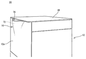
- FIG. 1 is an illustrative view showing an appearance of an image forming apparatus according to a first embodiment of the present invention.
- FIG. 2 is an illustrative view schematically showing an internal structure of the image forming apparatus of FIG. 3 is a perspective view showing the upper surface, upper front surface, and upper right surface of the image forming apparatus of FIG. 4 is a perspective view showing an upper surface and an upper front portion of the image forming apparatus of FIG.
- FIG. 5 is an illustrative view schematically showing a cross-sectional structure of a pixel of a display panel provided in the image forming apparatus of FIG.
- FIG. 6A is an illustrative view showing a method for detecting a touch position from a reflected image.
- FIG. 1 is an illustrative view showing an appearance of an image forming apparatus according to a first embodiment of the present invention.
- FIG. 2 is an illustrative view schematically showing an internal structure of the image forming apparatus of FIG. 3 is a perspective view showing
- FIG. 6B is an illustrative view showing a method of detecting a touch position by a shadow image.
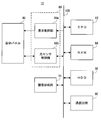
- FIG. 7 is a block diagram showing an electrical configuration of the image forming apparatus shown in FIG.
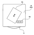
- FIG. 8 is an illustrative view showing a display panel in a state where a document is placed in the first embodiment.
- FIG. 9 is an illustrative view showing one example of a home screen included in the operation unit of the first embodiment.
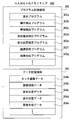
- FIG. 10 is an illustrative view showing one example of a memory map of the RAM shown in FIG.
- FIG. 11 is a flowchart showing an example of display processing of the image forming apparatus shown in FIG.
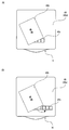
- FIG. 12A is a plan view showing a case where the operation unit and the document area overlap.
- FIG. 12A is a plan view showing a case where the operation unit and the document area overlap.
- FIG. 12B is a plan view showing a case where the operation unit is moved.
- FIG. 13 is a flowchart showing an example of the display process of the second embodiment.
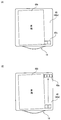
- FIG. 14A is a plan view showing a case where the ratio of the document area to the display panel is large.
- FIG. 14B is a plan view showing a case where the display size of the operation unit is reduced and moved.
- FIG. 15 is a flowchart showing an example of the display process of the third embodiment.
- FIG. 16 is a plan view showing divided areas in the fourth embodiment.
- FIG. 1 is an illustrative view showing an appearance of an image forming apparatus 10 according to a first embodiment of the present invention.
- FIG. 2 is an illustrative view schematically showing an internal structure of the image forming apparatus 10 of FIG.
- an image forming apparatus 10 forms a multicolor or single color image on a sheet (recording medium) by an electrophotographic method, and forms an image-formed sheet.
- the paper is discharged to the paper discharge unit 16.
- the image forming apparatus 10 is a multifunction peripheral (MFP) having a copying function, a printing function, a scanner function, a facsimile function, and the like.
- MFP multifunction peripheral
- a multifunction machine having a print function, a scanner function, and a facsimile function will be described as the image forming apparatus 10.
- the present invention is not limited to this. It does not have to have a function and a facsimile function.
- the surface facing the user's standing position that is, the surface on the side where the paper discharge unit 16 described later is provided is the front surface (front surface), and the front-back direction (depth direction) of the image forming apparatus 10 and its constituent members
- the left and right direction (lateral direction) of the image forming apparatus 10 and its constituent members are defined with reference to the state of the image forming apparatus 10 viewed from the user.
- the image forming apparatus 10 includes a substantially cuboid synthetic resin case 12 in which an image forming unit 14 and the like are incorporated.
- a paper discharge unit 16 having a paper outlet 76 that opens upward is provided at the upper portion of the front side.
- the image forming unit 14 includes components such as a photosensitive drum 20, a charging roller 22, a writing unit 24, a developing unit 26, a transfer roller 28, and a fixing unit 30. An image is formed on the conveyed paper, and the paper on which the image has been formed is discharged to the paper discharge unit 16.
- image data print image data
- image data read by an image reading unit 48b (display panel 48) described later or image data transmitted from an external computer is used. .
- the photosensitive drum 20 is an image carrier in which a photosensitive layer is formed on the surface of a conductive cylindrical substrate.
- the charging roller 22 is a member that charges the surface of the photosensitive drum 20 to a predetermined potential.
- the writing unit 24 is configured as a laser scanning unit (LSU) including a laser irradiation unit, a reflection mirror, and the like, and exposes the surface of the charged photoconductor drum 20 to expose the electrostatic latent image according to the image data. An image is formed on the surface of the photosensitive drum 20.
- the developing unit 26 visualizes the electrostatic latent image formed on the surface of the photosensitive drum 20 with toner.
- the transfer roller 28 is provided so as to form a transfer nip portion with the photosensitive drum 20. During image formation, a predetermined voltage is applied to the transfer roller 28 to form a transfer electric field at the transfer nip portion. The toner image formed on the surface of the photosensitive drum 20 is transferred to the sheet while the sheet passes through the transfer nip due to the action of the transfer electric field.
- the fixing unit 30 includes a heat roller and a pressure roller, and is disposed downstream of the transfer roller 28 in the sheet conveyance direction.
- the heat roller is set to have a predetermined fixing temperature.
- a sheet transport for feeding the sheet fed from the sheet feeding unit 32 by the pickup roller 34 and the sheet feeding roller 36 to the sheet discharging unit 16 through the transfer nip unit and the fixing nip unit.
- a path L1 is formed.
- a conveyance roller 38 for providing a driving force to the sheet supplementarily, a registration roller 40 for feeding the sheet to the transfer nip portion at a predetermined timing, and a sheet on which an image has been formed are discharged.
- a paper discharge roller 42 and the like for discharging to the paper section 16 are provided as appropriate.
- FIG. 3 is a perspective view showing the upper surface, upper front surface, and upper right surface of the image forming apparatus 10 of FIG.
- FIG. 4 is a perspective view showing the upper surface and upper front portion of the image forming apparatus 10 of FIG.
- the paper discharge unit 16 has a paper discharge space in which the paper on which the image is formed in the image forming unit 14 is discharged (accommodated). It is arranged vertically and opens upward. In the first embodiment, the paper discharge unit 16 is disposed in the upper part on the front side in the housing 12.
- the paper discharge unit 16 supports a paper discharge tray 72 that supports the front or back surface of the image-formed paper discharged into the paper discharge unit 16 and the rear end of the paper in the paper discharge direction.
- a rear end support portion 74 and a paper outlet 76 for taking out the paper to the outside of the paper discharge portion 16 are provided.
- the inner surface of the front wall 12 a of the housing 12 is used as the paper discharge tray 72. That is, the paper discharge tray 72 is integrally formed with the front wall 12 a and is provided so as to extend in a substantially vertical direction. The front side of the paper discharge unit 16 is covered with the front wall 12 a that functions as the paper discharge tray 72. The rear end support portion 74 is provided so as to be inclined slightly downward toward the paper discharge tray 72. A discharge port 78 for discharging the image-formed paper to the discharge unit 16 is formed at the end of the rear end support 74 opposite to the discharge tray 72. The paper discharge roller 42 described above is provided below the paper discharge port 78. The paper outlet 76 is formed in the upper part of the paper discharge space of the paper discharge unit 16 and opens upward.
- the image-formed paper is discharged substantially vertically upward with respect to the paper discharge unit 16 (that is, placed vertically), and is extracted upward from the paper outlet 76 by the user ( FIG. 1 and FIG. 2).
- the paper discharge unit 16 is provided with a paper pressing unit 80 that presses the paper toward the paper discharge tray 72 side.
- the paper discharged to the paper discharge unit 16 is appropriately brought close to the paper discharge tray 72 side by the inclination of the rear end support part 74 and the press of the paper pressing unit 80.
- a display panel 48 having a substantially rectangular flat plate constituting the top plate (upper wall) of the housing 12 is provided on the top of the housing 12. That is, the display panel 48 constitutes the top plate of the image forming apparatus 10.
- the display panel 48 is a sensor built-in liquid crystal panel in which a photosensor is built in each pixel of the liquid crystal panel, and a plurality of pixels arranged in a matrix and a photosensor 58 provided in each pixel. (See FIG. 5).
- the display panel 48 has an image reading function for reading an image and a touch detection function for detecting a position pointed (touched) by the user.
- the specific configuration of the display panel 48 having an image display function, an image reading function, and a touch detection function is described in Japanese Patent Application Laid-Open No. 2010-62940 filed by the present applicant.
- the apparatus is thinned, and the convenience and aesthetics of the image forming apparatus 10 are improved.
- the specific configuration of the display panel 48 can be changed as appropriate.
- FIG. 5 is an illustrative view schematically showing a cross-sectional structure of a pixel of the display panel 48 provided in the image forming apparatus 10 of FIG.
- the pixel included in the display panel 48 includes an active matrix substrate 50a disposed on the back side, a counter substrate 50b disposed on the front side, and a liquid crystal layer (liquid crystal shutter) 52.
- the active matrix substrate 50a is provided with a pixel electrode 54, a data signal line 56, an optical sensor 58, an alignment film 60, a polarizing plate 62, and the like.
- the counter substrate 50b is provided with color filters 64r (red), 64g (green), 64b (blue), a light shielding film 66, a counter electrode 68, an alignment film 60, a polarizing plate 62, and the like.
- the liquid crystal shutter 52 is provided between the active matrix substrate 50a and the counter substrate 50b.
- a backlight (light emitting unit) 70 is provided on the back side of the display panel 48. Such pixels are controlled to be turned on and off by opening and closing the liquid crystal shutter 52 with the backlight 70 turned on.
- the display panel 48 having such a configuration, when a document is placed on the polarizing plate 62 of the active matrix substrate 50a (display area of the display panel 48), light is emitted from the backlight 70.
- the light of the backlight 70 is reflected by the original on the polarizing plate 62, and the reflected light passes through the color filters 64r, 64g, 64b and is detected by the optical sensor 58, whereby the image of the original is read.
- a method for detecting the presence of an original on the polarizing plate 62 will be described. For example, when a part of the pixels of the display panel 48 are periodically turned on and in an imaging state (hereinafter referred to as “active state”), a document exists depending on whether or not the reflected light is received by the optical sensor 58 of each pixel. There is a way to detect whether or not. In this method, a region where an object that reflects light is present on the polarizing plate 62 is detected according to the position of the pixel that has received the reflected light. Then, it is determined what the object is based on the size of the area where the detected object exists.
- the object is an original or a user's finger (including a pointing device such as a touch pen).
- a predetermined size it is determined that the object is a document.
- the size of the area where the object is present is less than a predetermined size, it is determined that the object is a user's finger or the like.
- this method is merely an example, and the method for detecting the presence of a document on the polarizing plate 62 is not particularly limited.
- all the pixels of the display panel 48 are simultaneously activated to determine whether or not the reflected light is received by the optical sensor 58 of each pixel, and the document area is determined from the position (coordinate data) of the pixel receiving the reflected light. There is a way to detect.
- a plurality of pixels are sequentially activated so as to be randomly arranged from all the pixels of the display panel 48, and it is determined whether or not the reflected light is received at positions corresponding to all the pixels, and the reflected light is received.
- FIG. 6 (A) is an illustrative view showing a method for detecting a touch position from a reflected image.
- FIG. 6B is an illustrative view showing a method of detecting a touch position by a shadow image.
- such a display panel 48 can detect a position touched by the user (touch position) by detecting a reflected image of the user's fingertip or the like with the optical sensor 58.
- the light emitted from the backlight 70 is reflected by an object such as a user's finger.
- the reflected light reflected by the object enters the optical sensor 58.
- the level of the sensor output signal output from the optical sensor 58 varies.
- the touch position is detected according to the position of the pixel where the object is detected.
- the display panel 48 can detect the position touched by the user by detecting the image with the optical sensor 58.
- the optical sensor 58 included in the display panel 48 can also detect external light transmitted through the counter substrate 50b and the like. As shown in FIG. 6B, when there is an object such as a user's finger, the incidence of external light is prevented, and the amount of external light incident on the optical sensor 58 is reduced. For this reason, since the level of the sensor output signal output from the optical sensor 58 varies, it is determined that the object exists.
- reflected light (reflected image) of light emitted from the backlight 70 may be used, or a shadow image of external light may be used. Further, the position touched by the user may be detected using both the shadow image and the reflection image by using the above two types of detection methods in combination.
- FIG. 7 is a block diagram showing an electrical configuration of the image forming apparatus 10 shown in FIG.
- image forming apparatus 10 includes a CPU 82.
- a RAM 84, HDD 86, display panel control circuit 88, communication circuit 90, and image forming unit 14 are connected to the CPU 82 via the bus 100.
- a display panel 48 is connected to the display panel control circuit 88.
- the CPU 82 governs overall control of the image forming apparatus 10.
- the RAM 84 is used as a work area and a buffer area for the CPU 82.
- the HDD 86 is a main storage device of the image forming apparatus 10, and appropriately stores a control program and data for the CPU 82 to control the operation of each part of the image forming apparatus 10.
- the HDD 86 stores print image data transmitted from an external computer.
- another nonvolatile memory such as a flash memory may be provided instead of the HDD 86 or together with the HDD 86.
- the display panel control circuit 88 includes a display control unit 88a and an optical sensor control unit 88b.
- the display control unit 88a includes a GPU, a VRAM, and the like. Under the instruction of the CPU 82, the GPU uses the image generation data 304e stored in the RAM 84 to display various screens on the display panel 48. Data is generated in the VRAM, and the generated display image data is output to the display panel 48.
- the display control unit 88a controls turning on and off of the backlight 70 and controlling opening and closing of the liquid crystal shutter 52 of each pixel under the instruction of the CPU 82.
- the optical sensor control unit 88b transmits a timing control signal to an optical sensor driving circuit (not shown) of the optical sensor 58 under the instruction of the CPU 82 to execute detection of reflected light.
- the optical sensor control unit 88b controls reading of the detection signal of the optical sensor 58 under the instruction of the CPU 82.
- the optical sensor control unit 88b controls reading of the sensor output signal output from the optical sensor 58. Then, based on the sensor output signal acquired from the optical sensor control unit 88b, the CPU 82 determines whether the document is placed or the display panel 48 is touched when the amount of light received by the optical sensor 58 changes. When the document is placed, the CPU 82 generates image data based on the sensor output signal. That is, the image data read by the display panel 48 is generated. On the other hand, when the display panel 48 is touched, the CPU 82 generates coordinate data indicating the position on the display panel 48 according to the coordinates of the pixel where the reflected image or shadow image of the object is detected. That is, the touch coordinate data corresponding to the position where the user touches the display panel 48 is generated.
- the communication circuit 90 is a communication circuit for connecting to a network such as a LAN or the Internet.
- the communication circuit 90 is a wired communication circuit or a wireless communication circuit, and communicates with an external computer via a network in accordance with an instruction from the CPU 82.
- the communication circuit 90 can directly communicate with an external computer without using a network by short-range wireless or the like.
- FIG. 8 is an illustrative view showing the display panel 48 in a state where the document is placed in the first embodiment.
- FIG. 9 is an illustrative view showing one example of a home screen 110 included in the operation unit 48c of the first embodiment.
- the display panel 48 of the first embodiment includes an image display function (display unit) 48a, an image reading function (image reading unit) 48b, and a touch detection function (operation unit) 48c.
- the display panel 48 when the display panel 48 functions as the display unit 48a, the entire display area of the display panel 48 is used as the display unit 48a.
- the display panel 48 may display various images including the status of the image forming apparatus 10 and / or various messages, an image scanned by the image reading unit 48b, and an image received (acquired) from an external computer. A preview image is displayed.
- an auxiliary image including information for assisting the user's operation on the operation unit 48c may be displayed on the display panel 48.
- each part of the display panel 48 is controlled by the above-described method, and it is detected whether or not a document is placed, a document region is detected, or a document is scanned.
- the image reading unit 48b the area corresponding to the original area on the display panel 48 is used as the image reading unit 48b. That is, in the main scan, only the pixels corresponding to the document area are activated.
- the display panel 48 functions as the operation unit 48c
- a part of the display area of the display panel 48 is used as the operation unit 48c.
- the size (display size) of the operation unit 48c is set in advance.
- the operation unit 48c displays an operation screen including software keys (icons) and messages for receiving various settings or print instructions from the user.
- a home screen 110 for selecting a desired job from various jobs that can be executed by the image forming apparatus 10 is displayed on the operation unit 48c.
- the job means copying (including scanning of a document), printing (printing), transmission of a fax, and the like.
- the home screen 110 has a rectangular shape (rectangular shape), and is displayed (arranged) so as to coincide with the left-right direction of the image forming apparatus 10.
- the home screen 110 is provided with a plurality of icons.
- a predetermined function that can be executed in the image forming apparatus 10 is assigned to each of the plurality of icons.
- the home screen 110 is provided with a copy icon 112, a fax icon 114, and a scan icon 116 in order from the left side.
- the copy icon 112 is assigned a function for executing a copy job.
- a copy mode for executing a copy job is set.
- a copy setting screen is displayed on the operation unit 48c.
- the copy setting screen is a screen different from the home screen 110 described above, and is displayed instead of the home screen 110.
- the copy setting screen is provided with icons for changing various settings when executing a copy job.
- a function for executing a fax job is assigned to the fax icon 114.
- the scan icon 116 is assigned a function for executing a scan job.
- a fax mode for executing a fax job is set.
- a scan mode for executing a scan job is set.
- illustration is omitted, when the fax mode is set, a fax setting screen is displayed on the operation unit 48c.
- a scan setting screen is displayed on the operation unit 48c.
- the operation unit 48c is displayed on the display panel 48 when image display on the display panel 48 is started.
- the operation unit 48c is not displayed when the image display on the display panel 48 is completed.
- the power of the image forming apparatus 10 is turned on or when the image forming apparatus 10 is returned from the standby state (power saving mode)
- the image display on the display panel 48 is started.
- the power of the image forming apparatus 10 is turned off or when the image forming apparatus 10 is switched to the power saving mode, the image display on the display panel 48 is terminated.
- the operation unit 48c is displayed at the basic position when there is no document on the polarizing plate 62.
- the basic position is the front side on the right side (right front as viewed from the user).
- the basic position is that the end of the operation unit 48c (the end of the home screen 110) is a predetermined distance (for example, 3 mm to 10 mm) with respect to each of the right side end and the front side end of the display area of the display panel 48. It is a remote location.
- the operation unit 48c is displayed on the display panel 48 at a position corresponding to the document region. That is, the operation unit 48 c is displayed at a position corresponding to the position of the document placed on the polarizing plate 62.
- the display position of the operation unit 48c is set according to the document area. The operation unit 48c is moved to the set display position.
- the horizontal position of the operation unit 48c is set according to the horizontal position of the document area. Further, the position in the front-rear direction of the operation unit 48 c is set according to the position in the front-rear direction of the document area.
- the operation unit 48c is displayed (arranged) inside the width of the document area in the front-rear direction. That is, the operation unit 48c is displayed on the right side or the left side of the document area. This can be said that the operation unit 48c is displayed so that the operation unit 48c and the document area overlap in the front-rear direction when viewed from the left-right direction of the image forming apparatus 10. In the example shown in FIG. 8, the operation unit 48c is displayed on the right side of the document area.
- the operation unit 48c is displayed near the document area in the left-right direction. However, it can be said that the operation unit 48c is displayed in the vicinity of the document area is the operation unit 48c displayed at a position along the document area. The operation unit 48 c is displayed at a position closer to the document area than the edge of the display area of the display panel 48.
- the operation unit 48c is displayed at a position where the distance between the document region and a part of the operation unit 48c (the portion closest to the document region) is within a predetermined distance (for example, 5 to 10 mm).
- a predetermined distance for example, 5 to 10 mm.
- the distance between the document area and a part of the operation unit 48c is not particularly limited and can be changed as appropriate.
- the operation unit 48 c when the side (edge) extending in the vertical direction of the document area is inclined with respect to the front-rear direction in the image forming apparatus 10, at least a part of the operation unit 48 c is the document area in the left-right direction. It is displayed so that it is located inside the width of. That is, the operation unit 48c is displayed such that at least a part of the operation unit 48c and the document area are arranged in the front-rear direction. This can be said that the operation unit 48c is displayed so that the operation unit 48c and the document area overlap in the left-right direction when viewed from the front of the image forming apparatus 10.
- the above-described operation of the image forming apparatus 10 is realized by the CPU 82 executing a control program stored in the RAM 84. Specific processing will be described later with reference to a flowchart.
- FIG. 10 is an illustrative view showing one example of a memory map 300 of the RAM 84 shown in FIG.
- the RAM 84 includes a program storage area 302 and a data storage area 304.
- the program storage area 302 of the RAM 84 stores the control program for the image forming apparatus 10 as described above.
- the control program includes a display program 302a, an operation detection program 302b, a document detection program 302c, a document area detection program 302d, a display position setting program 302e, an image reading program 302f, and an image forming program 302g.
- the display program 302a is a program for controlling the display control unit 88a to display various screens including a preview image on the display panel 48.
- the display program 302 a is also a program for controlling the display control unit 88 a to display the operation unit 48 c including an operation screen such as the home screen 110 on the display panel 48.
- the operation detection program 302b is a program for acquiring a detection signal of the optical sensor 58 and detecting a touch operation on the display panel 48.
- the operation detection program 302b acquires the touch coordinate data output from the optical sensor control unit 88b and detects that various icons included in the operation screen displayed on the operation unit 48c of the display panel 48 have been operated. It is a program to do.
- the document detection program 302 c is a program for acquiring a detection signal from the optical sensor 58 and detecting that a document is placed on the polarizing plate 62.
- a document area detection program 302d is a program for acquiring a detection signal of the optical sensor 58 and detecting a document area when the document detection program 302c detects that a document is placed on the polarizing plate 62. It is.
- the display position setting program 302e is a program for setting the display position of the operation unit 48c in accordance with document area data 304b described later.
- the image reading program 302f is a program for reading an image of a document (main scanning) and outputting an image signal (image data) corresponding to the read image.
- the image forming program 302g is a program for controlling the image forming unit 14 to print an image read from a document on paper.
- program storage area 302 also stores programs for selecting and executing various functions.
- the data storage area 304 of the RAM 84 stores touch coordinate data 304a, document area data 304b, basic position data 304c, display position data 304d, image generation data 304e, and the like.
- the touch coordinate data 304a is touch coordinate data detected (acquired) according to the operation detection program 302b.
- the detected touch coordinate data 304a is stored in time series.
- the document area data 304b is data regarding a document area where a document detected in accordance with the document area detection program 302d exists. Specifically, the document area data 304b is a set of coordinate data of pixels for which it is determined that a document exists.
- the basic position data 304c is a set of coordinate data indicating the display position of the operation unit 48c when there is no document on the polarizing plate 62.
- the display position data 304d is data about the display position of the operation unit 48c set according to the display position setting program 302e. Specifically, the display position data 304d is the coordinate data corresponding to the center point of the area where the operation unit 48c is displayed or the coordinate data corresponding to the center point of the area where the operation unit 48c is displayed. It is. The display position data 304d may be a set of coordinate data corresponding to the area where the operation unit 48c is displayed.
- Image generation data 304e is data such as polygon data or texture data for generating display image data corresponding to various screens displayed on the display panel 48 (display unit 48a).
- the image generation data 304e includes operation screen data corresponding to the operation unit 48c.
- the operation screen data is data corresponding to an operation screen such as the home screen 110.
- the data storage area 304 stores image data read from an original by the image reading unit 48b or image data input from an external computer, and is necessary for executing a control program. Other data is stored, or a register necessary for executing the control program is provided.
- FIG. 11 is a flowchart showing an example of display processing of the image forming apparatus 10 shown in FIG. This display process is started when the image forming apparatus 10 is turned on or returned from the power saving mode.
- the CPU 82 displays the operation unit 48c at the basic position in step S1, and determines whether or not an object is present on the display panel 48 in step S3. To do. Here, it is determined whether or not the amount of light received by the optical sensor 58 of the pixel included in the display panel 48 has changed.
- step S3 If “NO” in the step S3, that is, if there is no object on the display panel 48, the process returns to the step S3. On the other hand, if “YES” in the step S3, that is, if there is an object on the display panel 48, it is determined whether or not the object existing on the display panel 48 is a document in a step S5.
- step S7 If “NO” in the step S5, that is, if the object existing on the display panel 48 is not an original (for example, when the display panel 48 is touched), other processes are executed in a step S7.
- the process proceeds to step S15.
- the other processing executed in step S7 includes processing for selecting each job according to a user instruction, processing for performing various settings for each job, and processing for starting and stopping each job. .
- step S5 that is, if the object existing on the display panel 48 is a document, a document region is detected in a step S9, and the display of the operation unit 48c is displayed in a step S11. The position is set, and the operation unit 48c is moved to the display position in step S13.
- step S15 it is determined whether or not to end the image display on the display panel 48.
- step S15 If “NO” in the step S15, that is, if the image display on the display panel 48 is not ended, the process returns to the step S3. On the other hand, if “YES” in the step S15, that is, if the image display on the display panel 48 is ended, the display position of the operation unit 48c is reset in a step S17, and the display process is ended. However, resetting the display position of the operation unit 48c means erasing the display position data 304d.
- the display panel 48 includes a display unit 48a that displays an image, an image reading unit 48b that reads a document placed on the display surface, and an operation unit 48c that receives an input operation by a user. Since it functions, it is possible to reduce manufacturing costs and downsize the apparatus.
- the operation unit 48c is displayed at a position corresponding to the document area, the user can freely place the document on the display panel 48, which is convenient.
- the operation unit 48c is displayed at a position along the document area, so that the user can easily recognize the operation unit and the user can easily operate the operation unit.
- the display panel 48 constitutes the top plate of the image forming apparatus 10
- the size of the display surface of the display panel 48 can be increased. Therefore, when the display panel 48 functions as the display unit 48a, the user can easily view the display unit 48a.
- the operation unit 48c is displayed inside the width of the document area in the front-rear direction.
- the present invention is not limited to this.
- the operation unit 48c may be displayed outside the width of the document area in the front-rear direction.
- the operation unit 48c is displayed on the front side or the back side of the document area. If the operation unit 48c is displayed on the front side of the document area, the distance from the user to the operation unit 48c is reduced, so that the operability of the operation unit 48c is good. If the operation unit 48c is displayed on the back side of the document area, even when there is a sheet discharged to the paper discharge unit 16, the paper discharge unit 16 is operated when the user operates the operation unit 48c. It is prevented that the paper discharged in the way gets in the way.
- the operation unit 48c is displayed at a position distant from the document area.
- the present invention is not limited to this.
- the operation unit 48c may be displayed at a position where the edge of the document area (document edge) and the edge of the operation unit 48c contact each other. In this way, since the operation unit 48c is displayed adjacent to the document area, the user can easily recognize the operation unit 48c and the user can easily operate the operation unit 48c.
- the image forming apparatus 10 according to the second embodiment is the same as that according to the first embodiment except that the operation unit 48c is displayed in a region outside the document other than the document region when the operation unit 48c and the document region overlap. Since the image forming apparatus 10 is the same as the image forming apparatus 10, the contents different from those in the first embodiment will be described, and redundant descriptions will be omitted.
- FIG. 12A is a plan view showing a case where the operation unit 48c and the document area overlap.
- FIG. 12B is a plan view showing a case where the operation unit 48c is moved.
- the operation unit 48c and the document area may overlap.
- the next document may be placed so as to overlap the operation unit 48c displayed at the display position set according to the previous document.
- the operation unit 48c and the document area overlap.
- the operation unit 48c and the document region overlap.
- the operation unit 48c when the operation unit 48c and the document area overlap, the operation unit 48c is moved to an area outside the document other than the document area.
- the movement of the operation unit 48c means that the display position of the operation unit 48c is newly set (changed) instead of the display position of the operation unit 48c when the operation unit 48c and the document area overlap.
- the operation unit 48c may be moved only in the left-right direction and not moved in the front-rear direction. In this case, the operation unit 48c is moved in a direction in which the movement distance from the position before the movement to the area outside the document is short on the right side or the left side. In the example shown in FIG. 12B, the operation unit 48c is moved to the right side.
- the display position of the operation unit 48c is set according to the document area as described in the first embodiment. In this case, when there are a plurality of documents, if the document area does not overlap the operation unit 48c displayed at the display position set according to the previous document, the display position of the operation unit 48c is newly set. May not be set.
- FIG. 13 is a flowchart showing an example of the display process of the second embodiment.
- the CPU 82 detects the document area in step S9, sets the display position of the operation unit 48c in the area outside the document in step S31, and sets the display position of the operation unit 48c in step S13. Is moved to the display position.
- step S31 if the operation unit 48c and the document area do not overlap at the already set display position of the operation unit 48c, the display position of the operation unit 48c may not be newly set.
- step S33 it is determined whether there is a next document.
- step S33 If “YES” in the step S33, that is, if there is a next document, the process returns to the step S9. On the other hand, if “NO” in the step S33, that is, if there is no original, the process proceeds to a step S15.
- step S9 the processing up to step S9 and the processing after step S15 are the same as those in the first embodiment, and the description thereof will be omitted.
- the operation unit 48c since the operation unit 48c is displayed in an area outside the document other than the document area, when the operation unit 48c overlaps the document area, the operation unit 48c is located outside the document area. Moved to. For this reason, even when a document is placed on the operation unit 48c, it is possible to prevent the operation unit 48c from being disabled.
- the operation unit 48c is moved only in the left-right direction, and is moved in a direction in which the moving distance from the position before the movement to the area outside the document is small. For this reason, since the operation part 48c is moved regularly, the user can predict the area where the operation part 48c is displayed, which is convenient.
- the operation unit 48c when the operation unit 48c and the document area overlap each other, the operation unit 48c is moved and displayed in the area outside the document.
- the present invention is not limited to this.
- the longitudinal direction of the operation unit 48c may be changed (rotated).
- the operation unit 48c may be rotated 90 ° counterclockwise or clockwise, and the direction of the edge of the operation unit 48c may be an angle that matches the direction of the edge of the document area (document edge). It may be rotated.
- the direction of the operation screen included in the operation unit 48c may be changed, or the arrangement of icons included in the operation screen may be changed.
- the icons included in the operation screen are arranged in the left-right direction (horizontal direction) before the longitudinal direction of the operation unit 48c is changed, the icons included in the operation screen are arranged in the front-rear direction (vertical direction). In this way, the arrangement of icons is changed.
- the operation unit 48c when the operation unit 48c and the document area overlap each other, the operation unit 48c is moved and displayed in the area outside the document.
- the present invention is not limited to this.
- the operation unit 48c overlaps various images such as an image including the status of the image forming apparatus 10 displayed on the display panel 48 and / or various messages and a preview image, the operation unit 48c is moved. You may make it display on area
- the operation unit 48c is moved only in the left-right direction, but it is not necessary to be limited to this.
- the operation unit 48c may be moved only in the front-rear direction.
- the operation unit 48c is moved in a direction in which the moving distance from the position before being moved to the area outside the document is small on the front side or the back side. In this way, since the operation unit 48c is moved regularly, the user can predict the area where the operation unit 48c is displayed, which is convenient.
- the operation unit 48c may be moved in the front-rear and left-right directions. In this case, the operation unit 48c is moved so that the moving distance from the position before being moved to the area outside the document becomes the shortest distance. In this way, since the operation unit 48c is moved to a close position, the user can predict the area where the operation unit 48c is displayed, which is convenient.
- the image forming apparatus 10 of the third embodiment is the same as the image forming apparatus 10 of the first embodiment except that the display size of the operation unit 48c is changed according to the document area. The contents different from the example will be described, and redundant description will be omitted.
- the display size of the operation unit 48c is enlarged or reduced according to the document area.
- FIG. 14A is a plan view showing a case where the ratio of the document area to the display panel 48 is large.
- FIG. 14B is a plan view showing a case where the display size of the operation unit 48c is reduced and moved.
- the display size of the operation unit 48c is reduced as shown in FIG.
- the operation unit 48c is not only reduced in display size, but also moved to a position where the operation unit 48c can be displayed in the largest area outside the original. That is, the display size of the operation unit 48c is set to a size that can be displayed when the operation unit 48c is moved. For example, in the example shown in FIG. 14B, on the right side of the display area of the display panel 48, the area for displaying the operation unit 48c is wider on the back side than on the front side. For this reason, the operation unit 48c is moved to the back side and is reduced to a size that can be displayed when the operation unit 48c is moved to the back side.
- the display size of the operation unit 48c may be enlarged.
- the operation unit 48c when the ratio of the document area to the display panel 48 is small, the display size of the operation unit 48c may be enlarged.
- the operation unit 48c when the operation unit 48c is displayed at the basic position, it may be enlarged to the maximum size that can be displayed at the basic position. Further, when the operation unit 48c is moved from the basic position, the operation unit 48c may be moved to a position where the operation unit 48c can be displayed most greatly and enlarged to a size that can be displayed at that position.
- FIG. 15 is a flowchart showing an example of the display process of the third embodiment.
- the CPU 82 detects the document area in step S9, and determines whether or not the entire operation unit 48c can be displayed in step S51.
- the operation screen data corresponding to the operation unit 48c included in the image generation data 304e and the document area data 304b it is determined whether or not there is an area for displaying the operation unit 48c having a default size. to decide.
- step S51 If “NO” in the step S51, that is, if it is impossible to display the entire operation unit 48c, the display size of the operation unit 48c is reduced (changes the display magnification of the operation unit 48c) in a step S53. Then, the process proceeds to step S11.
- step S51 determines whether or not the operation unit 48c can be enlarged and displayed in a step S55. .
- step S55 If “YES” in the step S55, that is, if the operation unit 48c can be enlarged and displayed, the display size of the operation unit 48c is enlarged (the display magnification of the operation unit 48c is changed) in a step S57. Then, the process proceeds to step S11. On the other hand, if “NO” in the step S55, that is, if the operation unit 48c cannot be enlarged and displayed, the process proceeds to the step S11 without passing through the step S57.
- step S9 the contents of the processing up to step S9 and the processing after step S11 are the same as those in the first embodiment, and thus the description thereof is omitted.
- the display size of the operation unit 48c is enlarged, so that the user can operate the operation unit 48c. It becomes easy to recognize.
- the image forming apparatus 10 according to the fourth embodiment is the same as the image forming apparatus 10 according to the first embodiment except that the area where the operation unit 48c is preferentially displayed is set. The contents different from the example will be described, and redundant description will be omitted.
- FIG. 16 is a plan view showing a divided region 480 in the fourth embodiment.
- the display area of the display panel 48 includes a plurality of divided areas 480.
- the display area of the display panel 48 includes four divided areas 480A to 480D divided by the center in the left-right direction and the center in the front-rear direction.
- the divided area 480A is a right front area.
- the divided area 480B is a left front area.
- the divided region 480C is a region on the back side on the right side.
- the divided region 480D is a left-side region on the left side.
- Priority for displaying the operation unit 48c is set in each of the divided areas 480A to 480D.
- the area on the front side is set to have a higher priority than the area on the back side.
- the right area is set to be higher in priority than the left area. Therefore, the divided area 480A is set to the first priority, the divided area 480B is set to the second priority, the divided area 480C is set to the third priority, and the divided area 480D is set to the fourth priority. .
- the operation unit 48c is displayed in the divided area 480A having the first priority.
- the operation unit 48c since the priority order for displaying the operation unit 48c in each of the plurality of divided areas 480 is set, the operation unit 48c is regularly displayed, and the user can operate the operation unit 48c. Can be predicted.
- the modifications of the third and fourth embodiments can be applied to the second embodiment.
- the modification of the fourth embodiment can also be applied to the third embodiment.
Landscapes
- Engineering & Computer Science (AREA)
- Human Computer Interaction (AREA)
- Multimedia (AREA)
- Signal Processing (AREA)
- Facsimiles In General (AREA)
- Facsimile Scanning Arrangements (AREA)
- User Interface Of Digital Computer (AREA)
- Accessory Devices And Overall Control Thereof (AREA)
- Control Or Security For Electrophotography (AREA)
- Image Input (AREA)
- Facsimile Heads (AREA)
Abstract
課題:製造コストの低減および装置の小型化を図ることができる。 解決手段:画像形成装置10は、CPU(82)、画像形成部(14)および表示パネル48を含む。表示パネル48は、画像を表示する表示部48aと、表示面上に載置された原稿を読み取る画像読取部48bと、ユーザによる入力操作を受け付ける操作部48cとして機能する。CPU(82)は、表示パネル48の表示面上において原稿が存在する原稿領域を検出し、操作部48cを、表示パネル48における、検出された原稿領域に応じた位置に表示させる。
Description
この発明は、画像読取装置、画像形成装置、制御プログラムおよび制御方法に関し、特にたとえば、画像を表示する表示パネルを備える、画像読取装置、画像形成装置、制御プログラムおよび制御方法に関する。
特許文献1には、背景技術の画像読取装置の一例が開示される。背景技術の画像読取装置は、コンタクトガラス、液晶パネル、発光部および操作部を備える。コンタクトガラスは、画像読取装置の上面に設けられる。液晶パネルは、コンタクトガラスの下方に重ねられる。発光部は、画像読取装置の内部に設けられ、コンタクトガラスに向かって下方から光を照射する。操作部は、ディスプレイおよび各種の操作キーを含み、画像読取装置の上面におけるコンタクトガラスとは異なる位置に設けられる。
しかしながら、背景技術の画像読取装置では、コンタクトガラスおよび液晶パネルなどを含む画像を読み取る画像読取領域と、ユーザの操作を受け付ける操作部とが別々に設けられる。このため、画像読取領域および操作部を別々に配置するスペースが必要となり、装置の大型化につながってしまう。また、背景技術の画像読取装置では、複数の表示機能を有する部品を複数備えるので、部品点数が増加し、製造コストが増大してしまうという問題がある。
それゆえに、この発明の主たる目的は、新規な、画像読取装置、画像形成装置、制御プログラムおよび制御方法を提供することである。
また、この発明の他の目的は、製造コストの低減および装置の小型化を図ることができる、画像読取装置、画像形成装置、制御プログラムおよび制御方法を提供することである。
第1の発明は、表示パネル、検出手段および表示制御手段を備える画像読取装置である。表示パネルは、液晶パネルの各画素に光センサを内蔵したセンサ内蔵液晶パネルであり、画像を表示する表示部と、ユーザによる入力操作を受け付ける操作部と、原稿を読み取る画像読取部として機能する。検出手段は、表示パネルの表示領域において原稿が存在する原稿領域を検出する。表示制御手段は、操作部を、表示パネルの表示領域における、検出手段で検出された原稿領域に応じた位置に表示させる。
第1の発明によれば、表示パネルが画像を表示する表示部と、ユーザによる入力操作を受け付ける操作部と、表示面上に載置された原稿を読み取る画像読取部として機能するので、製造コストの低減および装置の小型化を図ることができる。また、第1の発明では、操作部が、原稿領域に応じた位置に表示される。このため、ユーザは、表示パネルの上に自由に原稿を置くことができるので、便利である。
第2の発明は、第1の発明に従属する画像読取装置であって、表示制御手段は、操作部を原稿領域以外の原稿外領域に表示させる。
第2の発明では、操作部が原稿領域以外の原稿外領域に表示されるので、操作部と原稿領域とが重なった場合に、操作部が原稿領域以外の原稿外領域に移動される。このため、操作部の上に原稿が載置された場合であっても、ユーザが操作部を操作することが可能になる。
第3の発明は、第2の発明に従属する画像読取装置であって、表示制御手段は、操作部を、原稿領域と当該操作部の一部とが所定距離以内になる位置に表示させる。
第3の発明によれば、操作部が、その操作部の一部と原稿領域とが所定距離以内になる位置に表示されるので、ユーザが操作部を認識し易くなるとともに、ユーザが操作部を操作し易くなる。
第4の発明は、第1ないし第3のいずれかの発明に従属する画像読取装置であって、表示制御手段は、原稿領域に応じて、操作部の表示サイズを変更する。
第4の発明によれば、原稿領域に応じて、操作部の表示サイズが変更されるので、ユーザが操作部を認識し易くなるとともに、ユーザが操作部を操作し易くなる。したがって、画像読取装置の操作性を向上させることができる。
第5の発明は、第1ないし第4のいずれかの発明に従属する画像読取装置であって、表示パネルの表示領域は、複数の分割領域に分割され、複数の分割領域のそれぞれには、操作部を表示させる優先順位が設定され、表示制御手段は、操作部を、優先順位に従って複数の分割領域のいずれかに表示させる。
第5の発明によれば、複数の分割領域のそれぞれに操作部を表示させる優先順位が設定され、操作部は、優先順位に従って複数の分割領域のいずれかに表示されるので、ユーザは操作部が表示される領域を予測することができる。
第6の発明は、請求項1ないし5のいずれかに記載の画像読取装置を備える画像形成装置である。
第6の発明においても、第1の発明と同様に、製造コストの低減および装置の小型化を図ることができる。
第7の発明は、第6の発明に従属する画像形成装置であって、表示パネルは、画像形成装置の天板を構成する。
第7の発明によれば、表示パネルが画像形成装置の天板を構成するので、表示パネルの表示面の大きさを大きくとることができる。したがって、表示パネルが表示部として機能する場合は、ユーザが表示部を視認し易くなる。また、表示パネルが画像読取部として機能する場合は、原稿を置く場所の自由度が増すので、便利である。
第8の発明は、画像を表示する表示部と、ユーザによる入力操作を受け付ける操作部と、原稿を読み取る画像読取部として機能する表示パネルを備える画像読取装置のプロセッサによって実行される制御プログラムであって、画像読取装置のプロセッサを、表示パネルの表示領域において原稿が存在する原稿領域を検出する検出手段、および、操作部を、表示パネルの表示領域における、検出手段で検出された原稿領域に応じた位置に表示させる表示制御手段として機能させる。
第9の発明は、画像を表示する表示部と、ユーザによる入力操作を受け付ける操作部と、原稿を読み取る画像読取部として機能する表示パネルを備える画像読取装置のプロセッサが、(a)表示パネルの表示領域において原稿が存在する原稿領域を検出するステップ、および(b)操作部を、表示パネルの表示領域における、ステップ(a)で検出された原稿領域に応じた位置に表示させるステップを実行する。
第8および第9の各発明においても、第1の発明と同様に、製造コストの低減および装置の小型化を図ることができる。
この発明によれば、製造コストの低減および装置の小型化を図ることができる。
[第1実施例]
図1はこの発明の第1実施例である画像形成装置10の外観を示す図解図である。図2は図1の画像形成装置10の内部構造を概略的に示す図解図である。
図1はこの発明の第1実施例である画像形成装置10の外観を示す図解図である。図2は図1の画像形成装置10の内部構造を概略的に示す図解図である。
図1を参照して、この発明の第1実施例である画像形成装置10は、電子写真方式によって用紙(記録媒体)に対して多色または単色の画像を形成し、画像形成済みの用紙を排紙部16に排出する。この第1実施例では、画像形成装置10は、複写機能、プリント機能、スキャナ機能およびファクシミリ機能などを有する複合機(MFP:Multifunction Peripheral)である。
この第1実施例では、画像形成装置10として、プリント機能、スキャナ機能およびファクシミリ機能を備える複合機について説明するが、これに限定される必要はなく、少なくともスキャナ機能を有していれば、プリント機能およびファクシミリ機能は有していなくてよい。
なお、この明細書では、ユーザの立ち位置に対向する面、つまり後述する排紙部16が設けられる側の面を前面(正面)として画像形成装置10およびその構成部材の前後方向(奥行方向)を規定し、画像形成装置10およびその構成部材の左右方向(横方向)は、ユーザから画像形成装置10を見た状態を基準として規定する。
先ず、画像形成装置10の基本構成について概略的に説明する。図1および図2に示すように、画像形成装置10は、画像形成部14などが内蔵される略直方体状の合成樹脂製の筐体12を備え、詳細は後述するように、筐体12内の前面側上部には、上向きに開口する用紙取出口76を有する排紙部16が設けられる。
画像形成部14は、感光体ドラム20、帯電ローラ22、書込みユニット24、現像ユニット26、転写ローラ28および定着ユニット30等のコンポーネントを備え、筐体12の下部に設けられる給紙部32等から搬送される用紙上に画像を形成し、画像形成済みの用紙を排紙部16に排出する。なお、用紙に画像を形成するための画像データ(印刷画像データ)としては、後述する画像読取部48b(表示パネル48)で読み取った画像データまたは外部コンピュータから送信された画像データ等が利用される。
感光体ドラム20は、導電性を有する円筒状の基体の表面に感光層が形成された像担持体であり、帯電ローラ22は、感光体ドラム20の表面を所定の電位に帯電させる部材である。また、書込みユニット24は、レーザ照射部および反射ミラー等を備えたレーザスキャニングユニット(LSU)として構成され、帯電された感光体ドラム20の表面を露光することによって、画像データに応じた静電潜像を感光体ドラム20の表面に形成する。現像ユニット26は、感光体ドラム20の表面に形成された静電潜像をトナーによって顕像化する。
転写ローラ28は、感光体ドラム20との間に転写ニップ部を形成するように設けられる。画像形成時には、転写ローラ28に所定の電圧が印加されることによって、転写ニップ部に転写電界が形成される。そして、この転写電界の作用により、転写ニップ部を用紙が通過する間に、感光体ドラム20の表面に形成されたトナー像が用紙に転写される。
定着ユニット30は、ヒートローラおよび加圧ローラ等を備え、転写ローラ28の用紙搬送方向下流側に配置される。ヒートローラは、所定の定着温度となるように設定されており、ヒートローラと加圧ローラとの間の定着ニップ部を用紙が通過することによって、用紙に転写されたトナー像が溶融、混合および圧接されて、用紙に対してトナー像が熱定着される。
また、筐体12内には、ピックアップローラ34および給紙ローラ36によって給紙部32から送り出された用紙を、転写ニップ部および定着ニップ部を経由させて排紙部16に送るための用紙搬送路L1が形成される。この用紙搬送路L1には、用紙に対して補助的に推進力を与えるための搬送ローラ38、用紙を所定のタイミングで転写ニップ部に送り出すためのレジストローラ40、および画像形成済みの用紙を排紙部16に排出するための排紙ローラ42等が適宜設けられる。
図3は図1の画像形成装置10の上面、前面上部および右側面上部を示す斜視図である。図4は図1の画像形成装置10の上面および前面上部を示す斜視図である。
図1ないし図4に示すように、排紙部16は、画像形成部14において画像形成された用紙が排出(収容)される排紙空間を有しており、筐体12内の周縁部において縦向きに配置されて、上向きに開口する。この第1実施例では、排紙部16は、筐体12内の前面側上部に配置される。
具体的には、排紙部16は、排紙部16内に排出された画像形成済みの用紙の表面または裏面を支持する排紙トレイ72と、当該用紙の用紙排出方向における後端を支持する後端支持部74と、当該用紙を排紙部16の外部に取り出すための用紙取出口76とを備える。
そして、この第1実施例では、筐体12の前壁12aの内面側が排紙トレイ72として用いられる。すなわち、排紙トレイ72は、前壁12aと一体成形されて、略鉛直方向に延びるように設けられ、排紙部16の前面側は、排紙トレイ72として機能する前壁12aによって覆われる。また、後端支持部74は、排紙トレイ72に向かって少し下り勾配となるように傾斜して設けられる。この後端支持部74の排紙トレイ72と反対側の端部には、画像形成済みの用紙を排紙部16に排出するための排紙口78が形成される。上述の排紙ローラ42は、この排紙口78の下側に設けられる。そして、用紙取出口76は、排紙部16の排紙空間上部に形成されて、上向きに開口する。
すなわち、この第1実施例では、画像形成済みの用紙は、排紙部16に対して略鉛直上向きに排出されて(つまり縦置きされて)、用紙取出口76からユーザによって上方に抜き取られる(図1および図2参照)。
また、排紙部16には、排紙トレイ72側に向かって用紙を押さえる用紙押え部80が設けられる。排紙部16に排出された用紙は、後端支持部74の傾斜と用紙押え部80の押圧とによって、排紙トレイ72側に適切に寄せられる。
さらに、筐体12の上部には、筐体12の天板(上壁)を構成する略矩形平板状の表示パネル48が設けられる。つまり、表示パネル48は、画像形成装置10の天板を構成する。この第1実施例では、表示パネル48は、液晶パネルの各画素に光センサを内蔵したセンサ内蔵液晶パネルであって、マトリクス状に配置された複数の画素および各画素に設けられた光センサ58(図5参照)を含む。この表示パネル48は、画像を表示する画像表示機能の他に、画像を読み取る画像読取機能と、ユーザがポインティング(タッチ)した位置を検出するタッチ検出機能とを有している。
画像表示機能、画像読取機能およびタッチ検出機能を有する表示パネル48の具体的な構成については、本出願人による特開2010-62940号公報に記載されているので、参照されたい。このような表示パネル48を用いることにより、装置が薄型化されて、画像形成装置10の利便性および美感が向上する。ただし、表示パネル48の具体的構成については、適宜変更可能である。
図5は図1の画像形成装置10が備える表示パネル48の画素の断面構造を概略的に示す図解図である。
図5に示すように、表示パネル48に含まれる画素は、背面側に配置されるアクティブマトリクス基板50aと、表面側に配置される対向基板50bと、液晶層(液晶シャッタ)52を備える。アクティブマトリクス基板50aには、画素電極54、データ信号線56、光センサ58、配向膜60および偏光板62などが設けられる。対向基板50bには、カラーフィルタ64r(赤),64g(緑),64b(青)、遮光膜66、対向電極68、配向膜60および偏光板62などが設けられる。液晶シャッタ52は、アクティブマトリクス基板50aおよび対向基板50bの間に設けられる。また、表示パネル48の背面側には、バックライト(発光部)70が設けられる。このような画素は、バックライト70を点灯した状態で、液晶シャッタ52が開閉されることにより、点灯および消灯を制御される。
このような構成の表示パネル48では、アクティブマトリクス基板50aの偏光板62上(表示パネル48の表示領域)に原稿が載置されると、バックライト70から光が照射される。バックライト70の光は、偏光板62上の原稿によって反射され、この反射光がカラーフィルタ64r,64g,64bを通過して光センサ58で検出されることによって、原稿の画像が読み取られる。
ただし、この表示パネル48では、原稿のコピーまたは読み取り(原稿サイズの判定時と区別するため、「本スキャン」ということがある)が行われる前に、偏光板62上に原稿が存在するかどうか(載置されたかどうか)が検出される。偏光板62上に原稿が存在することが検出されると、偏光板62上において原稿が存在する領域(以下、「原稿領域」という)が検出される。そして、原稿領域が検出された後に、原稿が本スキャンされる。
偏光板62上に原稿が存在することを検出する方法について説明する。たとえば、表示パネル48の一部の画素を定期的に点灯および撮像状態(以下、「アクティブ状態」という)として、各画素の光センサ58で反射光を受光するかどうかに応じて原稿が存在するかどうかを検出する方法がある。この方法では、反射光を受光した画素の位置に応じて、偏光板62上に光が反射する対象物が存在する領域が検出される。そして、検出された対象物が存在する領域の大きさによってその対象物が何であるかが判断される。第1実施例では、対象物が原稿であるか、ユーザの手指(タッチペンなどのポインティングデバイスを含む)などであるかが判断される。ここでは、対象物が存在する領域の大きさが、所定の大きさ以上である場合に、その対象物が原稿であると判断される。一方、対象物が存在する領域の大きさが、所定の大きさ未満である場合に、その対象物がユーザの手指などであると判断される。ただし、この方法は一例であり、偏光板62上に原稿が存在することを検出する方法は特に限定されない。
次に、原稿領域を検出する方法について説明する。たとえば、表示パネル48のすべての画素を一斉にアクティブ状態として、各画素の光センサ58で反射光を受光するかどうかを判断し、反射光を受光した画素の位置(座標データ)から原稿領域を検出する方法がある。
また、原稿領域を検出する他の方法として、表示パネル48の一部の画素をアクティブ状態として、反射光を受光した画素の位置から原稿のエッジの位置を特定し、原稿領域を検出する方法がある。
さらに、表示パネル48のすべての画素からランダムな配置となるように複数の画素を順次アクティブ状態として、すべての画素に対応する位置について反射光を受光するかどうかを判断し、反射光を受光した画素の位置から原稿領域を検出する方法がある。
なお、これらの方法は一例であり、原稿領域を検出する方法は特に限定されない。
次に、ユーザが指先などで偏光板62をタッチした位置を検出する方法について説明する。
図6(A)は反射像によってタッチ位置を検出する方法を示す図解図である。図6(B)は影像によってタッチ位置を検出する方法を示す図解図である。
たとえば、このような表示パネル48は、ユーザの指先などの反射像を光センサ58で検出することによって、ユーザがタッチした位置(タッチ位置)を検出することができる。具体的には、図6(A)に示すように、バックライト70から照射された光は、ユーザの指などの対象物によって反射される。対象物によって反射された反射光は、光センサ58に入射される。このとき、光センサ58から出力されるセンサ出力信号のレベルが変動する。センサ出力信号のレベルが所定値(閾値)以上である場合に、対象物が存在することが判断される。そして、対象物が検出された画素の位置に応じて、タッチ位置が検出される。
さらに、表示パネル48は、影像を光センサ58で検出することによって、ユーザがタッチした位置を検出することができる。表示パネル48に含まれる光センサ58は、対向基板50bなどを透過した外光を検出することもできる。図6(B)に示すように、ユーザの指などの対象物がある場合は、外光の入射が妨げられ、光センサ58に入射される外光の光量が減る。このため、光センサ58から出力されるセンサ出力信号のレベルが変動するので、対象物が存在することが判断される。
このように、ユーザがタッチした位置を検出する場合には、バックライト70より照射された光の反射光(反射像)を用いても良いし、外光による影像を用いても良い。また、上記2種類の検出方法を併用して、影像と反射像とを両方を用いてユーザがタッチした位置を検出するようにしても良い。
図7は図1に示す画像形成装置10の電気的な構成を示すブロック図である。図7を参照して、画像形成装置10はCPU82を含む。CPU82には、バス100を介してRAM84、HDD86、表示パネル制御回路88、通信回路90および画像形成部14が接続される。また、表示パネル制御回路88には表示パネル48が接続される。
CPU82は、画像形成装置10の全体的な制御を司る。RAM84は、CPU82のワーク領域およびバッファ領域として用いられる。
HDD86は、画像形成装置10の主記憶装置であって、CPU82が画像形成装置10の各部位の動作を制御するための制御プログラムおよびデータ等を適宜記憶する。また、HDD86は、外部コンピュータから送信された印刷画像データを記憶する。ただし、HDD86に代えて、または、HDD86とともに、フラッシュメモリ等の他の不揮発性メモリを設けてもよい。
表示パネル制御回路88は、表示制御部88aおよび光センサ制御部88bを含む。表示制御部88aは、GPUおよびVRAMなどを含んでおり、CPU82の指示の下、GPUは、RAM84に記憶された画像生成データ304eを用いて表示パネル48に種々の画面を表示するための表示画像データをVRAMに生成し、生成した表示画像データを表示パネル48に出力する。また、表示制御部88aは、CPU82の指示の下、バックライト70の点灯および消灯を制御したり、各画素の液晶シャッタ52の開閉を制御したりする。
光センサ制御部88bは、CPU82の指示の下、光センサ58の光センサ駆動回路(不図示)に、タイミング制御信号を送信し、反射光の検出を実行させる。また、光センサ制御部88bは、CPU82の指示の下、光センサ58の検出信号の読み出しを制御したりする。
また、光センサ制御部88bは、光センサ58から出力されるセンサ出力信号の読み出しを制御する。そして、CPU82は、光センサ制御部88bから取得したセンサ出力信号に基づいて、光センサ58で受光される光量が変化した場合、原稿が載置されたか表示パネル48がタッチされたかを判断する。原稿が載置された場合には、CPU82は、センサ出力信号に基づいて画像データを生成する。つまり、表示パネル48で読み取った画像データを生成する。一方、表示パネル48がタッチされた場合には、CPU82は、対象物の反射像または影像が検出された画素の座標に応じて、表示パネル48における位置を示す座標データを生成する。つまり、ユーザが表示パネル48をタッチした位置に対応するタッチ座標データを生成する。
通信回路90は、LANまたはインターネットなどのネットワークに接続するための通信回路である。この通信回路90は、有線通信回路または無線通信回路であり、CPU82からの指示に従って、ネットワークを介して、外部のコンピュータと通信する。ただし、通信回路90は、近距離無線などによって、ネットワークを介さずに、外部のコンピュータと直接通信することが可能である。
なお、図7に示す画像形成装置10の電気的な構成は単なる一例であり、これに限定される必要はない。
図8は第1実施例における原稿が載置された状態の表示パネル48を示す図解図である。図9は第1実施例の操作部48cに含まれるホーム画面110の一例を示す図解図である。
第1実施例の表示パネル48は、画像表示機能(表示部)48a、画像読取機能(画像読取部)48bおよびタッチ検出機能(操作部)48cを備える。
図8に示すように、表示パネル48が表示部48aとして機能する場合には、表示パネル48の表示領域の全体が表示部48aとして用いられる。この場合、表示パネル48には、画像形成装置10のステータスまたは/および各種のメッセージ等を含む各種の画像、画像読取部48bでスキャンした画像および外部のコンピュータから受信(取得)した画像のようなプレビュー画像などが表示される。また、表示パネル48が表示部48aとして機能する場合には、表示パネル48には、操作部48cにおけるユーザの操作を支援するための情報を含む補助画像が表示されても良い。
表示パネル48が画像読取部48bとして機能する場合には、表示パネル48の表示領域の一部または全体が画像読取部48bとして用いられる。この場合、上述した方法で、表示パネル48の各部が制御され、原稿が載置されたかどうかが検出されたり、原稿領域が検出されたり、原稿が本スキャンされたりする。ただし、原稿が本スキャンされる場合には、表示パネル48における原稿領域に対応する領域が画像読取部48bとして用いられる。つまり、本スキャンにおいては、原稿領域に対応する画素のみがアクティブ状態にされる。
表示パネル48が操作部48cとして機能する場合には、表示パネル48の表示領域の一部が操作部48cとして用いられる。ただし、操作部48cの大きさ(表示サイズ)は、予め設定されている。操作部48cには、各種設定または印刷指示などをユーザから受け付けるためのソフトウェアキー(アイコン)およびメッセージ等を含む操作画面が表示される。操作画面の一例として、操作部48cには、画像形成装置10が実行可能な各種のジョブから所望のジョブを選択するためのホーム画面110が表示される。ただし、この第1実施例では、ジョブは、コピー(原稿のスキャンを含む)、プリント(印刷)およびファックスの送信などを意味する。
図8および図9に示すように、ホーム画面110は、矩形(長方形)形状であり、画像形成装置10の左右方向と一致するように表示(配置)される。このホーム画面110には、複数のアイコンが設けられる。複数のアイコンのそれぞれには、画像形成装置10において実行可能な所定の機能が割り当てられる。図9に示す例では、ホーム画面110には、左側から順に、コピーアイコン112、ファクスアイコン114およびスキャンアイコン116が設けられる。
コピーアイコン112には、コピージョブを実行する機能が割り当てられる。コピーアイコン112がユーザによって選択(タッチ)されると、コピージョブを実行するためのコピーモードが設定される。図示は省略するが、コピーモードが設定されると、操作部48cにコピー設定画面が表示される。コピー設定画面は、上述したホーム画面110とは別の画面であり、ホーム画面110に代えて表示される。このコピー設定画面には、コピージョブを実行する際の各種設定を変更するためのアイコンなどが設けられる。
ファクスアイコン114には、ファクスジョブを実行する機能が割り当てられる。また、スキャンアイコン116には、スキャンジョブを実行する機能が割り当てられる。ファクスアイコン114がユーザによってタッチされると、ファクスジョブを実行するためのファクスモードが設定される。また、スキャンアイコン116がユーザによってタッチされると、スキャンジョブを実行するためのスキャンモードが設定される。図示は省略するが、ファクスモードが設定されると、操作部48cにファクス設定画面が表示される。また、スキャンモードが設定されると、操作部48cにスキャン設定画面が表示される。
操作部48cは、表示パネル48の画像表示が開始されたときに、表示パネル48に表示される。また、操作部48cは、表示パネル48の画像表示が終了されると、非表示にされる。ただし、画像形成装置10の電源がオンされたり、画像形成装置10がスタンバイ状態(省電力モード)から復帰されたりしたときなどに、表示パネル48の画像表示が開始される。また、画像形成装置10の電源がオフされたり、画像形成装置10が省電力モードに遷移されたりしたときなどに、表示パネル48の画像表示が終了される。
また、操作部48cは、偏光板62上に原稿が存在しない場合には、基本位置に表示される。図示は省略するが、基本位置は、右側の前面側(ユーザから見て右手前)である。たとえば、基本位置は、操作部48cの端部(ホーム画面110の端部)が、表示パネル48の表示領域の右側端部および前面側端部のそれぞれに対して所定距離(たとえば3mm~10mm)離れた位置である。
ただし、操作部48cは、偏光板62上に原稿が載置された場合(偏光板62上に原稿が存在する場合)には、表示パネル48における、原稿領域に応じた位置に表示される。つまり、操作部48cは、偏光板62上に載置された原稿の位置に応じた位置に表示される。原稿領域が検出されると、原稿領域に応じて、操作部48cの表示位置が設定される。操作部48cは、設定された表示位置に移動される。
具体的には、原稿領域の左右方向の位置に応じて、操作部48cの左右方向の位置が設定される。また、原稿領域の前後方向の位置に応じて、操作部48cの前後方向の位置が設定される。
たとえば、操作部48cは、前後方向における原稿領域の幅の内側に表示(配置)される。つまり、操作部48cは、原稿領域の右側または左側に表示される。このことは、画像形成装置10の左右方向から見たときに、前後方向において操作部48cと原稿領域とが重なるように操作部48cが表示されるとも言える。図8に示す例では、操作部48cは、原稿領域の右側に表示される。
また、操作部48cは、左右方向における原稿領域の近傍に表示される。ただし、操作部48cが原稿領域の近傍に表示されるとは、操作部48cが原稿領域に沿った位置に表示されるとも言える。また、操作部48cは、表示パネル48の表示領域の端部よりも原稿領域に近い位置に表示される。
具体的には、操作部48cは、原稿領域と操作部48cの一部(原稿領域に最も近い部分)との距離が、所定距離(たとえば5~10mm)以内になる位置に表示される。ただし、原稿領域と操作部48cの一部との距離は、特に限定される必要は無く、適宜変更可能である。
また、図8に示すように、原稿領域の上下方向に延びる辺(エッジ)が画像形成装置10における前後方向に対して傾斜する場合は、操作部48cの少なくとも一部が、左右方向における原稿領域の幅の内側に位置するように表示される。つまり、操作部48cは、操作部48cの少なくとも一部と、原稿領域とが前後方向に並ぶように表示される。このことは、画像形成装置10の正面から見たときに、左右方向において操作部48cと原稿領域とが重なるように操作部48cが表示されるとも言える。
画像形成装置10の上記のような動作は、CPU82がRAM84に記憶された制御プログラムを実行することによって実現される。具体的な処理については、後でフロー図を用いて説明する。
図10は図7に示すRAM84のメモリマップ300の一例を示す図解図である。図10に示すように、RAM84は、プログラム記憶領域302およびデータ記憶領域304を含む。RAM84のプログラム記憶領域302には、上述したように、画像形成装置10の制御プログラムが記憶される。制御プログラムは、表示プログラム302a、操作検出プログラム302b、原稿検出プログラム302c、原稿領域検出プログラム302d、表示位置設定プログラム302e、画像読取プログラム302fおよび画像形成プログラム302gを含む。
表示プログラム302aは、表示制御部88aを制御して、プレビュー画像などを含む各種の画面を表示パネル48に表示するためのプログラムである。また、表示プログラム302aは、表示制御部88aを制御して、ホーム画面110などの操作画面を含む操作部48cを表示パネル48に表示させるためのプログラムでもある。
操作検出プログラム302bは、光センサ58の検出信号を取得して、表示パネル48へのタッチ操作を検出するためのプログラムである。たとえば、操作検出プログラム302bは、光センサ制御部88bから出力されたタッチ座標データを取得して、表示パネル48の操作部48cに表示される操作画面に含まれる各種アイコンが操作されたことを検出するためのプログラムである。
原稿検出プログラム302cは、光センサ58の検出信号を取得して、偏光板62上に原稿が載置されたことを検出するためのプログラムである。
原稿領域検出プログラム302dは、原稿検出プログラム302cによって偏光板62上に原稿が載置されたことが検出された場合に、光センサ58の検出信号を取得して、原稿領域を検出するためのプログラムである。
表示位置設定プログラム302eは、後述する原稿領域データ304bに応じて、操作部48cの表示位置を設定するためのプログラムである。
画像読取プログラム302fは、原稿の画像を読み取り(本スキャンし)、読み取った画像に対応する画像信号(画像データ)を出力するためのプログラムである。
画像形成プログラム302gは、画像形成部14を制御して、原稿から読み取った画像などを用紙に印刷するためのプログラムである。
なお、図示は省略するが、プログラム記憶領域302には、各種の機能を選択および実行するためのプログラムなども記憶される。
RAM84のデータ記憶領域304には、タッチ座標データ304a、原稿領域データ304b、基本位置データ304c、表示位置データ304dおよび画像生成データ304eなどが記憶される。
タッチ座標データ304aは、操作検出プログラム302bに従って検出(取得)されたタッチ座標データである。検出されたタッチ座標データ304aは、時系列に従って記憶される。
原稿領域データ304bは、原稿領域検出プログラム302dに従って検出される原稿が存在する原稿領域についてのデータである。具体的には、原稿領域データ304bは、原稿が存在することが判定された画素の座標データの集合である。
基本位置データ304cは、偏光板62上に原稿が存在しない場合の操作部48cの表示位置を示す座標データの集合である。
表示位置データ304dは、表示位置設定プログラム302eに従って設定される操作部48cの表示位置についてのデータである。具体的には、表示位置データ304dは、表示位置データ304dは、操作部48cが表示される領域の中心点に対応する座標データまたは操作部48cが表示される領域の重心点に対応する座標データである。また、表示位置データ304dは、操作部48cが表示される領域に対応する座標データの集合であっても良い。
画像生成データ304eは、表示パネル48(表示部48a)に表示する、各種の画面に対応する表示画像データを生成するためのポリゴンデータまたはテクスチャデータ等のデータである。また、画像生成データ304eには、操作部48cに対応する操作画面データが含まれる。ただし、操作画面データは、ホーム画面110などの操作画面に対応するデータである。
なお、図示は省略するが、データ記憶領域304には、画像読取部48bで原稿から読み取られた画像データまたは外部のコンピュータから入力される画像データなどが記憶されたり、制御プログラムの実行に必要な他のデータが記憶されたり、制御プログラムの実行に必要なレジスタが設けられたりする。
図11は図1に示す画像形成装置10の表示処理の一例を示すフロー図である。この表示処理は、画像形成装置10の電源がオンされたり、省電力モードから復帰されたりすると開始される。図11に示すように、CPU82は、表示処理を開始すると、ステップS1で、基本位置に操作部48cを表示して、ステップS3で、表示パネル48の上に対象物が存在するかどうかを判断する。ここでは、表示パネル48に含まれる画素の光センサ58で受光される光量が変化したかどうかを判断する。
ステップS3で“NO”であれば、つまり、表示パネル48の上に対象物が存在しない場合は、ステップS3に戻る。一方、ステップS3で“YES”であれば、つまり、表示パネル48の上に対象物が存在する場合は、ステップS5で、表示パネル48の上に存在する対象物が原稿かどうかを判断する。
ステップS5で“NO”であれば、つまり、表示パネル48の上に存在する対象物が原稿でない場合(たとえば表示パネル48がタッチされた場合)は、ステップS7で、その他の処理を実行して、ステップS15に進む。ステップS7で実行されるその他の処理としては、ユーザの指示に従って各ジョブが選択される処理、各ジョブにおける各種の設定が行われる処理、および各ジョブが開始されたり停止されたりする処理が該当する。
一方、ステップS5で“YES”であれば、つまり、表示パネル48の上に存在する対象物が原稿である場合は、ステップS9で、原稿領域を検出し、ステップS11で、操作部48cの表示位置を設定し、ステップS13で、操作部48cを表示位置に移動させる。
続いて、ステップS15で、表示パネル48における画像表示を終了するかどうかを判断する。
ステップS15で“NO”であれば、つまり、表示パネル48における画像表示を終了しない場合は、ステップS3に戻る。一方、ステップS15で“YES”であれば、つまり、表示パネル48における画像表示を終了する場合は、ステップS17で、操作部48cの表示位置をリセットして、表示処理を終了する。ただし、操作部48cの表示位置をリセットすることとは、表示位置データ304dを消去することを意味する。
この第1実施例によれば、表示パネル48が、画像を表示する表示部48aと、表示面上に載置された原稿を読み取る画像読取部48bと、ユーザによる入力操作を受け付ける操作部48cとして機能するので、製造コストの低減および装置の小型化を図ることができる。
また、第1実施例によれば、操作部48cが、原稿領域に応じた位置に表示されるので、ユーザは表示パネル48の上に自由に原稿を置くことができ、便利である。
さらに、第1実施例によれば、操作部48cは、原稿領域に沿った位置に表示されるので、ユーザが操作部を認識し易くなるとともに、ユーザが操作部を操作し易くなる。
加えて、第1実施例によれば、表示パネル48が画像形成装置10の天板を構成するので、表示パネル48の表示面の大きさを大きくとることができる。したがって、表示パネル48が表示部48aとして機能する場合は、ユーザが表示部48aを視認し易くなる。
なお、第1実施例では、操作部48cが前後方向における原稿領域の幅の内側に表示されるようにしたが、これに限定される必要は無い。たとえば、操作部48cが前後方向における原稿領域の幅の外側に表示されても良い。この場合、操作部48cは、原稿領域の前面側または背面側に表示される。操作部48cが原稿領域の前面側に表示されるようにすれば、ユーザから操作部48cまでの距離が近くなるので、操作部48cの操作性が良い。操作部48cが原稿領域の背面側に表示されるようにすれば、排紙部16に排出された用紙が存在する場合であっても、ユーザが操作部48cを操作する際に排紙部16に排出された用紙が邪魔になることが防止される。
また、第1実施例では、操作部48cが原稿領域に対して離れた位置に表示されるようにしたが、これに限定される必要は無い。たとえば、操作部48cは、原稿領域のエッジ(原稿のエッジ)と、操作部48cのエッジとが接触する位置に表示されても良い。このようにすれば、操作部48cが原稿領域に隣接して表示されるので、ユーザが操作部48cを認識し易くなるとともに、ユーザが操作部48cを操作し易くなる。
[第2実施例]
第2実施例の画像形成装置10は、操作部48cと原稿領域とが重なった場合に、操作部48cが原稿領域以外の原稿外領域に表示されるようにした以外は、第1実施例の画像形成装置10と同じであるため、第1実施例と異なる内容について説明し、重複した説明については省略することにする。
[第2実施例]
第2実施例の画像形成装置10は、操作部48cと原稿領域とが重なった場合に、操作部48cが原稿領域以外の原稿外領域に表示されるようにした以外は、第1実施例の画像形成装置10と同じであるため、第1実施例と異なる内容について説明し、重複した説明については省略することにする。
図12(A)は操作部48cと原稿領域とが重なる場合を示す平面図である。図12(B)は操作部48cを移動させた場合を示す平面図である。
図12(A)に示すように、操作部48cと原稿領域とが重なる場合がある。たとえば、原稿が複数枚存在するときに、前の原稿に応じて設定された表示位置に表示される操作部48cに重なるように次の原稿が載置されることがある。この場合、操作部48cと原稿領域とが重なる。また、基本位置に表示された操作部48cに重なるように原稿が載置された場合には、操作部48cと原稿領域とが重なる。
図12(B)に示すように、第2実施例では、操作部48cと原稿領域とが重なる場合には、操作部48cが原稿領域以外の原稿外領域に移動される。ただし、操作部48cが移動されるとこととは、操作部48cと原稿領域とが重なる場合の操作部48cの表示位置に代えて、操作部48cの表示位置が新たに設定(変更)されることを意味する。たとえば、操作部48cは、左右方向にのみ移動され、前後方向には移動されないようにしても良い。この場合、操作部48cは、右側または左側のうち、移動される前の位置から原稿外領域に移動されるまでの移動距離が少ない方向に移動される。図12(B)に示す例では、操作部48cは、右側に移動される。
また、操作部48cと原稿領域とが重ならない場合には、第1実施例で説明したように、原稿領域に応じて、操作部48cの表示位置が設定される。この場合、原稿が複数枚存在するときに、前の原稿に応じて設定された表示位置に表示される操作部48cに、原稿領域が重ならない場合には、新たに操作部48cの表示位置が設定されないことがある。
以下、フロー図を用いて、第2実施例における画像形成装置10の表示処理について説明するが、第1実施例で説明した表示処理と同じ処理については同じ参照符号を付し、重複した内容については、説明を省略するまたは簡単に説明することにする。
図13は第2実施例の表示処理の一例を示すフロー図である。図13に示すように、CPU82は、表示処理を開始すると、ステップS9で原稿領域を検出し、ステップS31で、原稿外領域に操作部48cの表示位置を設定し、ステップS13で、操作部48cを表示位置に移動させる。ただし、ステップS31では、既に設定された操作部48cの表示位置において、操作部48cと原稿領域とが重ならない場合には、新たに操作部48cの表示位置を設定しないことがある。
続いて、ステップS33で、次の原稿があるかどうかを判断する。ここでは、一旦原稿が検出されなくなってから、所定時間以内に、再度原稿が検出されたかどうかを判断する。
ステップS33で“YES”であれば、つまり、次の原稿がある場合は、ステップS9に戻る。一方、ステップS33で“NO”であれば、つまり、の原稿が無い場合は、ステップS15に進む。
なお、ステップS9までの処理およびステップS15以降の処理の内容については、第1実施例と同じであるので説明を省略する。
この第2実施例によれば、操作部48cが原稿領域以外の原稿外領域に表示されるので、操作部48cと原稿領域とが重なった場合に、操作部48cが原稿領域以外の原稿外領域に移動される。このため、操作部48cの上に原稿が載置された場合であっても、操作部48cが操作できなくなることを防止することができる。
また、第2実施例によれば、操作部48cが左右方向にのみ移動され、移動される前の位置から原稿外領域に移動されるまでの移動距離が少ない方向に移動される。このため、操作部48cが規則的に移動されるので、ユーザは操作部48cが表示される領域を予測することができ、便利である。
なお、第2実施例では、操作部48cと原稿領域とが重なる場合には、操作部48cを移動させて原稿外領域に表示されるようにしたが、これに限定される必要は無い。たとえば、操作部48cと原稿領域とが重なる場合に、操作部48cを移動させることに加えて、またはこれに代えて、操作部48cの長手方向の向きを変更(回転)させるようにしても良い。この場合、操作部48cは、左回りまたは右回りに90°回転されても良いし、操作部48cのエッジの向きが原稿領域のエッジ(原稿のエッジ)の向きと一致する角度になるように回転されても良い。また、操作部48cの長手方向の向きを変更する場合、操作部48cに含まれる操作画面の向きを変更させても良いし、操作画面に含まれるアイコンの並びを変更させても良い。たとえば、操作部48cの長手方向の向きを変更させる前に操作画面に含まれるアイコンが左右方向(横方向)に並んでいる場合は、操作画面に含まれるアイコンが前後方向(縦方向)に並ぶようにアイコンの並びが変更される。
また、第2実施例では、操作部48cと原稿領域とが重なる場合には、操作部48cを移動させて原稿外領域に表示されるようにしたが、これに限定される必要は無い。たとえば、操作部48cが、表示パネル48に表示された画像形成装置10のステータスまたは/および各種のメッセージを含む画像およびプレビュー画像などの各種の画像と重なる場合には、操作部48cを移動させて各種の画像が表示される領域以外の領域に表示されるようにしても良い。
さらに、第2実施例では、操作部48cが左右方向にのみ移動されるようにしたが、これに限定される必要は無い。たとえば、操作部48cは、前後方向にのみ移動されても良い。この場合、操作部48cは、前面側または背面側のうち、移動される前の位置から原稿外領域に移動されるまでの移動距離が少ない方向に移動される。このようにすれば、操作部48cが規則的に移動されるので、ユーザは操作部48cが表示される領域を予測することができ、便利である。
また、操作部48cは、前後左右方向に移動されても良い。この場合、操作部48cは、移動される前の位置から原稿外領域に移動されるまでの移動距離が最短距離になるように移動される。このようにすれば、操作部48cが近い位置に移動されるので、ユーザは操作部48cが表示される領域を予測することができ、便利である。
[第3実施例]
第3実施例の画像形成装置10は、原稿領域に応じて、操作部48cの表示サイズを変更するようにした以外は、第1実施例の画像形成装置10と同じであるため、第1実施例と異なる内容について説明し、重複した説明については省略することにする。
[第3実施例]
第3実施例の画像形成装置10は、原稿領域に応じて、操作部48cの表示サイズを変更するようにした以外は、第1実施例の画像形成装置10と同じであるため、第1実施例と異なる内容について説明し、重複した説明については省略することにする。
第3実施例の画像形成装置10では、原稿領域に応じて、操作部48cの表示サイズが拡大されたり、縮小されたりする。
図14(A)は表示パネル48に対して原稿領域の占める割合が大きい場合を示す平面図である。図14(B)は操作部48cの表示サイズを縮小して移動させた場合を示す平面図である。
図14(A)に示すように、表示パネル48に対して原稿領域の占める割合が大きい場合には、初期設定の大きさの操作部48cを表示させるための充分な領域が存在しないことがある。つまり、原稿領域以外の原稿外領域において、操作部48cを表示させるためのスペースが存在しない場合がある。この場合、操作部48cが移動されたとしても、操作部48cと原稿領域とが重なってしまう。つまり、操作部48cの全体を表示することが不可能である。
第3実施例では、操作部48cの全体を表示することが不可能であると判断されると、図14(B)に示すように、操作部48cの表示サイズが縮小される。また、操作部48cは、表示サイズが縮小されるだけでなく、原稿外領域において、最も大きく操作部48cを表示させることができる位置に移動される。つまり、操作部48cの表示サイズは、操作部48cが移動された場合に表示可能な大きさに設定される。たとえば、図14(B)に示す例では、表示パネル48の表示領域の右側において、前面側よりも背面側の方が、操作部48cを表示させるための領域が広い。このため、操作部48cは、背面側に移動されるとともに、操作部48cを背面側に移動させた場合に表示可能な大きさに縮小される。
また、図示は省略するが、表示パネル48に対して原稿領域の占める割合が小さい場合には、操作部48cの表示サイズが拡大されても良い。たとえば、操作部48cが基本位置に表示される場合、基本位置において表示可能な最大の大きさまで拡大されても良い。また、操作部48cが基本位置から移動される場合、最も大きく操作部48cを表示させることができる位置に移動され、その位置において表示可能な大きさまで拡大されても良い。
以下、フロー図を用いて、第3実施例における画像形成装置10の表示処理について説明するが、第1実施例で説明した表示処理と同じ処理については同じ参照符号を付し、重複した内容については、説明を省略するまたは簡単に説明することにする。
図15は第3実施例の表示処理の一例を示すフロー図である。図15に示すように、CPU82は、表示処理を開始すると、ステップS9で原稿領域を検出し、ステップS51で、操作部48cの全体を表示することが可能かどうかを判断する。ここでは、画像生成データ304eに含まれる操作部48cに対応する操作画面データと、原稿領域データ304bとを用いて、初期設定の大きさの操作部48cを表示させるための領域があるかどうかを判断する。
ステップS51で“NO”であれば、つまり、操作部48cの全体を表示することが不可能であれば、ステップS53で、操作部48cの表示サイズを縮小(操作部48cの表示倍率を変更)して、ステップS11に進む。
一方、ステップS51で“YES”であれば、つまり、操作部48cの全体を表示することが可能であれば、ステップS55で、操作部48cを拡大して表示することが可能かどうかを判断する。
ステップS55で“YES”であれば、つまり、操作部48cを拡大して表示することが可能であれば、ステップS57で、操作部48cの表示サイズを拡大(操作部48cの表示倍率を変更)して、ステップS11に進む。一方、ステップS55で“NO”であれば、つまり、操作部48cを拡大して表示することが不可能であれば、ステップS57を経ずにステップS11に進む。
なお、ステップS9までの処理およびステップS11以降の処理の内容については、第1実施例と同じであるので説明を省略する。
この第3実施例によれば、初期設定の大きさの操作部48cを表示させるための充分な領域が存在する場合には、操作部48cの表示サイズが拡大されるので、ユーザが操作部48cを認識し易くなる。
また、第3実施例によれば、初期設定の大きさの操作部48cを表示させるための充分な領域が存在しない場合には、操作部48cの表示サイズが縮小されるので、操作部48cが操作できなくなることを防止することができる。
[第4実施例]
第4実施例の画像形成装置10は、操作部48cが優先的に表示される領域が設定されるようにした以外は、第1実施例の画像形成装置10と同じであるため、第1実施例と異なる内容について説明し、重複した説明については省略することにする。
[第4実施例]
第4実施例の画像形成装置10は、操作部48cが優先的に表示される領域が設定されるようにした以外は、第1実施例の画像形成装置10と同じであるため、第1実施例と異なる内容について説明し、重複した説明については省略することにする。
図16は第4実施例における分割領域480を示す平面図である。第4実施例では、表示パネル48の表示領域は、複数の分割領域480を含む。たとえば、図16に示すように、表示パネル48の表示領域は、左右方向の中央と、前後方向の中央とで区切られた4つの分割領域480A~480Dを含む。分割領域480Aは、右側の前面側の領域である。分割領域480Bは、左側の前面側の領域である。分割領域480Cは、右側の背面側の領域である。分割領域480Dは、左側の背面側の領域である。
分割領域480A~480Dのそれぞれには、操作部48cを表示させる優先順位が設定される。たとえば、背面側の領域よりも前面側の領域が優先順位の上位になるように設定される。また、左側の領域よりも右側の領域が優先順位の上位になるように設定される。したがって、分割領域480Aが優先順位1位に設定され、分割領域480Bが優先順位2位に設定され、分割領域480Cが優先順位3位に設定され、分割領域480Dが優先順位4位に設定される。
そして、第4実施例では、原稿領域が検出されると、優先順位が上位の分割領域480から順に、操作部48cの全体を表示することが可能かどうかが判断される。
先ず、優先順位1位の分割領域480Aに操作部48cの全体を表示することが可能かどうかが判断される。ここでは、初期設定の大きさの操作部48cを表示させるための充分な領域が優先順位1位の分割領域480Aに存在するかどうかが判断される。分割領域480Aに操作部48cの全体を表示することが可能であれば、操作部48cは、分割領域480Aに表示される。分割領域480Aに操作部48cの全体を表示することが不可能であれば、優先順位が次の順位である分割領域480Bに操作部48cの全体を表示することが可能かどうかが判断される。以下、優先順位の上位から順に、同じように判断される。このように、第4実施例では、操作部48cは、優先順位に従って分割領域480A~480Dのいずれかに表示される。
この第4実施例によれば、複数の分割領域480のそれぞれに操作部48cを表示させる優先順位が設定されるので、操作部48cが規則的に表示されることになり、ユーザは操作部48cが表示される領域を予測することができる。
なお、第3実施例および第4実施例の変形は、第2実施例にも適用することができる。また、第4実施例の変形は、第3実施例にも適用することができる。ただし、第4実施例の変形を第3実施例に適用する場合には、先に優先順位が上位の分割領域480から順に、操作部48cの全体を表示することが可能かどうかが判断される。そして、いずれの分割領域480においても初期設定の大きさの操作部48cを表示させるための充分な領域が存在しない場合には、操作部48cの表示サイズが縮小される。また、いずれかの分割領域480において操作部48cを表示させるための充分な領域が存在する場合には、操作部48cの表示サイズが拡大されても良い。
また、上述の実施例で挙げた具体的な数値、画面構成等は一例であり、実際の製品に応じて適宜変更することが可能である。
さらに、上述の実施例で示したフロー図の各ステップは、同じ結果が得られるのであれば、処理される順番は適宜変更することが可能である。
10 …画像形成装置
12 …筐体
14 …画像形成部
16 …排紙部
48 …表示パネル
48a…表示部
48b…画像読取部
48c…操作部
82 …CPU
110…ホーム画面
12 …筐体
14 …画像形成部
16 …排紙部
48 …表示パネル
48a…表示部
48b…画像読取部
48c…操作部
82 …CPU
110…ホーム画面
Claims (9)
- 画像を表示する表示部と、ユーザによる入力操作を受け付ける操作部と、原稿を読み取る画像読取部として機能する表示パネル、
前記表示パネルの表示領域において原稿が存在する原稿領域を検出する検出手段、および
前記操作部を、前記表示パネルの表示領域における、前記検出手段で検出された前記原稿領域に応じた位置に表示させる表示制御手段を備える、画像読取装置。 - 前記表示制御手段は、前記操作部を前記原稿領域以外の原稿外領域に表示させる、請求項1記載の画像読取装置。
- 前記表示制御手段は、前記操作部を、前記原稿領域と当該操作部の一部とが所定距離以内になる位置に表示させる、請求項2記載の画像読取装置。
- 前記表示制御手段は、前記原稿領域に応じて、前記操作部の表示サイズを変更する、請求項1ないし3のいずれかに記載の画像読取装置。
- 前記表示パネルの前記表示領域は、複数の分割領域に分割され、
前記複数の分割領域のそれぞれには、前記操作部を表示させる優先順位が設定され、
前記表示制御手段は、前記操作部を、前記優先順位に従って前記複数の分割領域のいずれかに表示させる、請求項1ないし4のいずれかに記載の画像読取装置。 - 請求項1ないし5のいずれかに記載の画像読取装置を備える、画像形成装置。
- 前記表示パネルは、前記画像形成装置の天板を構成する、請求項6記載の画像形成装置。
- 画像を表示する表示部と、ユーザによる入力操作を受け付ける操作部と、原稿を読み取る画像読取部として機能する表示パネルを備える画像読取装置のプロセッサによって実行される制御プログラムであって、
前記画像読取装置のプロセッサを、
前記表示パネルの表示領域において原稿が存在する原稿領域を検出する検出手段、および
前記操作部を、前記表示パネルの表示領域における、前記検出手段で検出された前記原稿領域に応じた位置に表示させる表示制御手段として機能させる、制御プログラム。 - 画像を表示する表示部と、ユーザによる入力操作を受け付ける操作部と、原稿を読み取る画像読取部として機能する表示パネルを備える画像読取装置のプロセッサが、
(a)前記表示パネルの表示領域において原稿が存在する原稿領域を検出するステップ、および
(b)前記操作部を、前記表示パネルの表示領域における、前記ステップ(a)で検出された前記原稿領域に応じた位置に表示させるステップを実行する、制御方法。
Priority Applications (2)
| Application Number | Priority Date | Filing Date | Title |
|---|---|---|---|
| US16/495,036 US10965825B2 (en) | 2017-03-23 | 2018-02-15 | Image reading apparatus comprising display panel which serves as operation portion and image reader, image forming apparatus, non-transitory storage medium, and control method |
| CN201880016384.2A CN110419207B (zh) | 2017-03-23 | 2018-02-15 | 图像读取装置、图像形成装置、存储介质以及控制方法 |
Applications Claiming Priority (2)
| Application Number | Priority Date | Filing Date | Title |
|---|---|---|---|
| JP2017056850A JP6832765B2 (ja) | 2017-03-23 | 2017-03-23 | 画像読取装置、画像形成装置、制御プログラムおよび制御方法 |
| JP2017-056850 | 2017-03-23 |
Publications (1)
| Publication Number | Publication Date |
|---|---|
| WO2018173568A1 true WO2018173568A1 (ja) | 2018-09-27 |
Family
ID=63584307
Family Applications (1)
| Application Number | Title | Priority Date | Filing Date |
|---|---|---|---|
| PCT/JP2018/005332 Ceased WO2018173568A1 (ja) | 2017-03-23 | 2018-02-15 | 画像読取装置、画像形成装置、制御プログラムおよび制御方法 |
Country Status (4)
| Country | Link |
|---|---|
| US (1) | US10965825B2 (ja) |
| JP (1) | JP6832765B2 (ja) |
| CN (1) | CN110419207B (ja) |
| WO (1) | WO2018173568A1 (ja) |
Citations (4)
| Publication number | Priority date | Publication date | Assignee | Title |
|---|---|---|---|---|
| JP2009188851A (ja) * | 2008-02-08 | 2009-08-20 | Sharp Corp | 原稿読取装置及び画像形成装置 |
| JP2009194419A (ja) * | 2008-02-12 | 2009-08-27 | Sharp Corp | 原稿読取装置及び画像形成装置 |
| JP2009232033A (ja) * | 2008-03-21 | 2009-10-08 | Sharp Corp | 画像形成装置及びプログラム |
| JP2013126256A (ja) * | 2011-12-15 | 2013-06-24 | Toshiba Corp | 情報処理装置、画像取得プログラム |
Family Cites Families (12)
| Publication number | Priority date | Publication date | Assignee | Title |
|---|---|---|---|---|
| JP2005244755A (ja) | 2004-02-27 | 2005-09-08 | Kyocera Mita Corp | 画像形成装置 |
| JP4089711B2 (ja) * | 2005-07-08 | 2008-05-28 | コニカミノルタビジネステクノロジーズ株式会社 | 画像読み取り装置とそれを有する画像形成装置 |
| JP4510900B2 (ja) * | 2008-01-29 | 2010-07-28 | シャープ株式会社 | 原稿読取装置及び画像形成装置 |
| US20090204543A1 (en) * | 2008-02-11 | 2009-08-13 | Henry Jose Salazar Moure | System and method of selectively distributing media content to a consumer and preventing the unauthorized sharing of media content |
| JP5236536B2 (ja) * | 2009-03-09 | 2013-07-17 | シャープ株式会社 | 画像表示/像検知装置、制御方法、制御プログラム、および該制御プログラムを記録したコンピュータ読み取り可能な記録媒体 |
| US8854639B2 (en) * | 2010-01-27 | 2014-10-07 | Kyocera Mita Corporation | Control device, image forming apparatus, and reading device |
| JP2011191511A (ja) * | 2010-03-15 | 2011-09-29 | Sharp Corp | 画像形成装置 |
| CN102202149B (zh) * | 2010-03-23 | 2014-02-26 | 京瓷办公信息系统株式会社 | 图像显示装置及显示控制方法 |
| US8582131B2 (en) * | 2010-10-25 | 2013-11-12 | Sharp Kabushiki Kaisha | Image forming apparatus |
| CN103324420B (zh) * | 2012-03-19 | 2016-12-28 | 联想(北京)有限公司 | 一种多点触控板输入操作识别方法及电子设备 |
| JP5775864B2 (ja) * | 2012-12-12 | 2015-09-09 | 京セラドキュメントソリューションズ株式会社 | スキャナー装置及び画像形成装置 |
| CN104346026B (zh) * | 2013-07-29 | 2019-07-05 | 阿尔派株式会社 | 显示操作装置以及显示操作装置的显示方法 |
-
2017
- 2017-03-23 JP JP2017056850A patent/JP6832765B2/ja active Active
-
2018
- 2018-02-15 US US16/495,036 patent/US10965825B2/en active Active
- 2018-02-15 CN CN201880016384.2A patent/CN110419207B/zh active Active
- 2018-02-15 WO PCT/JP2018/005332 patent/WO2018173568A1/ja not_active Ceased
Patent Citations (4)
| Publication number | Priority date | Publication date | Assignee | Title |
|---|---|---|---|---|
| JP2009188851A (ja) * | 2008-02-08 | 2009-08-20 | Sharp Corp | 原稿読取装置及び画像形成装置 |
| JP2009194419A (ja) * | 2008-02-12 | 2009-08-27 | Sharp Corp | 原稿読取装置及び画像形成装置 |
| JP2009232033A (ja) * | 2008-03-21 | 2009-10-08 | Sharp Corp | 画像形成装置及びプログラム |
| JP2013126256A (ja) * | 2011-12-15 | 2013-06-24 | Toshiba Corp | 情報処理装置、画像取得プログラム |
Also Published As
| Publication number | Publication date |
|---|---|
| JP6832765B2 (ja) | 2021-02-24 |
| JP2018160796A (ja) | 2018-10-11 |
| US20200028981A1 (en) | 2020-01-23 |
| CN110419207B (zh) | 2021-09-14 |
| US10965825B2 (en) | 2021-03-30 |
| CN110419207A (zh) | 2019-11-05 |
Similar Documents
| Publication | Publication Date | Title |
|---|---|---|
| JP5518009B2 (ja) | 画像形成装置、画像編集方法、コンピュータプログラム及び記録媒体 | |
| US9516182B2 (en) | Image forming apparatus that enhances operability on screen displayed as split screens | |
| US20220385773A1 (en) | Display device and image forming apparatus capable of determining whether user's hand having made gesture is right or left hand based on detection result of touch panel and allowing display to display screen for right-hand gesture operation or screen for left-hand gesture operation based on determination result | |
| CN102447809B (zh) | 操作装置、图像形成装置以及操作方法 | |
| US20180284672A1 (en) | Image forming apparatus, image forming system, storage medium and control method | |
| JP5078459B2 (ja) | 画像形成装置 | |
| JP2015080104A (ja) | 画像読取装置、画像読取装置の制御方法、プログラム、及び記憶媒体 | |
| US20200106902A1 (en) | Display device, storage medium storing control program for display device, and method of controlling display device | |
| JP7397941B2 (ja) | 画像読取装置および画像読取装置の制御方法 | |
| CN110419207B (zh) | 图像读取装置、图像形成装置、存储介质以及控制方法 | |
| JP5892332B2 (ja) | 表示制御装置表示システム表示制御プログラム | |
| JP5949211B2 (ja) | 表示制御装置、遠隔操作システム、遠隔操作方法、および遠隔操作プログラム | |
| CN109756641B (zh) | 图像形成装置、记录介质以及控制方法 | |
| JP6618367B2 (ja) | 画像形成装置、画像形成装置の制御プログラムおよび画像形成装置の制御方法 | |
| JP5361146B2 (ja) | 画像形成装置及びその制御方法 | |
| JP2019166723A (ja) | 画像形成装置、制御プログラムおよび制御方法 | |
| JP6581709B2 (ja) | 画像処理方法 | |
| US10725413B2 (en) | Image forming apparatus, control program, and control method | |
| JP5876451B2 (ja) | 画像形成装置、記録媒体決定方法、コンピュータプログラム及び記録媒体 | |
| JP6200528B2 (ja) | 画像形成装置及び画像処理方法 | |
| CN121325536A (zh) | 图像形成装置 | |
| JP5570194B2 (ja) | 画像形成装置 | |
| JP2021197022A (ja) | 情報処理装置 | |
| JP2011043624A (ja) | 画像形成装置 | |
| JP2017185821A (ja) | 画像形成装置及び画像処理方法 |
Legal Events
| Date | Code | Title | Description |
|---|---|---|---|
| 121 | Ep: the epo has been informed by wipo that ep was designated in this application |
Ref document number: 18770372 Country of ref document: EP Kind code of ref document: A1 |
|
| NENP | Non-entry into the national phase |
Ref country code: DE |
|
| 122 | Ep: pct application non-entry in european phase |
Ref document number: 18770372 Country of ref document: EP Kind code of ref document: A1 |