WO2018173526A1 - 音声処理用コンピュータプログラム、音声処理装置及び音声処理方法 - Google Patents
音声処理用コンピュータプログラム、音声処理装置及び音声処理方法 Download PDFInfo
- Publication number
- WO2018173526A1 WO2018173526A1 PCT/JP2018/004182 JP2018004182W WO2018173526A1 WO 2018173526 A1 WO2018173526 A1 WO 2018173526A1 JP 2018004182 W JP2018004182 W JP 2018004182W WO 2018173526 A1 WO2018173526 A1 WO 2018173526A1
- Authority
- WO
- WIPO (PCT)
- Prior art keywords
- sound
- frame
- directional
- frequency spectrum
- probability
- Prior art date
- Legal status (The legal status is an assumption and is not a legal conclusion. Google has not performed a legal analysis and makes no representation as to the accuracy of the status listed.)
- Ceased
Links
Images





Classifications
-
- H—ELECTRICITY
- H04—ELECTRIC COMMUNICATION TECHNIQUE
- H04R—LOUDSPEAKERS, MICROPHONES, GRAMOPHONE PICK-UPS OR LIKE ACOUSTIC ELECTROMECHANICAL TRANSDUCERS; ELECTRIC HEARING AIDS; PUBLIC ADDRESS SYSTEMS
- H04R3/00—Circuits for transducers
- H04R3/005—Circuits for transducers for combining the signals of two or more microphones
-
- H—ELECTRICITY
- H04—ELECTRIC COMMUNICATION TECHNIQUE
- H04R—LOUDSPEAKERS, MICROPHONES, GRAMOPHONE PICK-UPS OR LIKE ACOUSTIC ELECTROMECHANICAL TRANSDUCERS; ELECTRIC HEARING AIDS; PUBLIC ADDRESS SYSTEMS
- H04R1/00—Details of transducers, loudspeakers or microphones
- H04R1/20—Arrangements for obtaining desired frequency or directional characteristics
- H04R1/32—Arrangements for obtaining desired frequency or directional characteristics for obtaining desired directional characteristic only
- H04R1/34—Arrangements for obtaining desired frequency or directional characteristics for obtaining desired directional characteristic only by using a single transducer with sound reflecting, diffracting, directing or guiding means
- H04R1/345—Arrangements for obtaining desired frequency or directional characteristics for obtaining desired directional characteristic only by using a single transducer with sound reflecting, diffracting, directing or guiding means for loudspeakers
-
- H—ELECTRICITY
- H04—ELECTRIC COMMUNICATION TECHNIQUE
- H04R—LOUDSPEAKERS, MICROPHONES, GRAMOPHONE PICK-UPS OR LIKE ACOUSTIC ELECTROMECHANICAL TRANSDUCERS; ELECTRIC HEARING AIDS; PUBLIC ADDRESS SYSTEMS
- H04R1/00—Details of transducers, loudspeakers or microphones
- H04R1/20—Arrangements for obtaining desired frequency or directional characteristics
- H04R1/32—Arrangements for obtaining desired frequency or directional characteristics for obtaining desired directional characteristic only
- H04R1/40—Arrangements for obtaining desired frequency or directional characteristics for obtaining desired directional characteristic only by combining a number of identical transducers
- H04R1/406—Arrangements for obtaining desired frequency or directional characteristics for obtaining desired directional characteristic only by combining a number of identical transducers microphones
-
- H—ELECTRICITY
- H04—ELECTRIC COMMUNICATION TECHNIQUE
- H04R—LOUDSPEAKERS, MICROPHONES, GRAMOPHONE PICK-UPS OR LIKE ACOUSTIC ELECTROMECHANICAL TRANSDUCERS; ELECTRIC HEARING AIDS; PUBLIC ADDRESS SYSTEMS
- H04R2430/00—Signal processing covered by H04R, not provided for in its groups
- H04R2430/20—Processing of the output signals of the acoustic transducers of an array for obtaining a desired directivity characteristic
-
- H—ELECTRICITY
- H04—ELECTRIC COMMUNICATION TECHNIQUE
- H04R—LOUDSPEAKERS, MICROPHONES, GRAMOPHONE PICK-UPS OR LIKE ACOUSTIC ELECTROMECHANICAL TRANSDUCERS; ELECTRIC HEARING AIDS; PUBLIC ADDRESS SYSTEMS
- H04R2499/00—Aspects covered by H04R or H04S not otherwise provided for in their subgroups
- H04R2499/10—General applications
- H04R2499/13—Acoustic transducers and sound field adaptation in vehicles
-
- H—ELECTRICITY
- H04—ELECTRIC COMMUNICATION TECHNIQUE
- H04R—LOUDSPEAKERS, MICROPHONES, GRAMOPHONE PICK-UPS OR LIKE ACOUSTIC ELECTROMECHANICAL TRANSDUCERS; ELECTRIC HEARING AIDS; PUBLIC ADDRESS SYSTEMS
- H04R3/00—Circuits for transducers
- H04R3/04—Circuits for transducers for correcting frequency response
Definitions
- the present invention relates to an audio processing computer program, an audio processing apparatus, and an audio processing method for processing an audio signal including audio collected using a plurality of microphones, for example.
- a voice processing device that processes a voice signal obtained by collecting voices with a plurality of microphones.
- a technique for suppressing sound from other than the specific direction in the sound signal has been studied (for example, Patent Documents). 1 and 2).
- voices coming from directions other than the specific direction are suppressed.
- the technique described in Patent Document 2 not only the sound from the sound source located in a specific direction but also the sound from another sound source located in another assumed direction is not suppressed.
- the range of non-target directions is too wide and noise suppression is insufficient. As a result, there is a possibility that the ease of listening to the sound from the sound source located in the specific direction is not sufficiently improved.
- the present invention provides a computer program for audio processing that can output not only audio from a sound source located in a priority direction but also audio from other sound sources located in another direction without being suppressed. For the purpose.
- a computer program for speech processing includes a first speech signal generated by the first speech input unit and a second speech input unit generated by a second speech input unit arranged at a position different from the first speech input unit.
- 2 audio signals are converted into a first frequency spectrum and a second frequency spectrum in the frequency domain for each frame having a predetermined time length, and the first frequency spectrum and the second frequency spectrum are converted for each frame. Based on the above, the probability that only the sound source located in the second direction out of the first direction and the second direction different from the first direction to which sound reception is prioritized emits sound is calculated.
- not only the sound from the sound source located in the priority direction but also the sound from other sound sources located in the other direction can be output without being suppressed.
- this audio processing device in the audio signals obtained by a plurality of audio input units, a first direction in which a preferred sound source is located and a second sound source in which other sound sources are assumed are located for each frame. Among the directions, the probability that only the sound source located in the second direction emits sound is calculated. And this audio processing device is not limited to the first directional audio signal including the audio arriving from the first direction and the second directional audio including the audio arriving from the second direction for the frame having high probability. A signal is also output. That is, when the probability is high, the sound processing device temporarily extends the sound receiving direction to include the second direction.
- FIG. 1 is a schematic configuration diagram of a voice input device in which a voice processing device according to one embodiment is mounted.
- the voice input device 1 includes two microphones 11-1 and 11-2, two analog / digital converters 12-1 and 12-2, a voice processing device 13, and a communication interface unit 14.
- the voice input device 1 is mounted on, for example, a vehicle (not shown), collects voices uttered by a driver or other passengers, and sends voice signals including the voices to a navigation system (not shown) or hands-free. Output to a phone (not shown).
- the sound processing device 13 sets the directivity characteristics of the received sound so as to suppress sound from directions other than the direction in which the driver is located.
- the voice processing device 13 has a high probability that only the passenger speaks out of the direction in which the driver is located (first direction) and the direction in which the fellow passenger is located (second direction). The directivity is changed so as not to suppress the voice coming from the second direction.
- Each of the microphones 11-1 and 11-2 is an example of a voice input unit.
- the microphone 11-1 and the microphone 11-2 are, for example, between a driver that is a sound source to be collected and a passenger in the passenger seat that is another sound source (hereinafter simply referred to as a passenger). For example, it is arranged near the ceiling of the instrument panel or the passenger compartment. In the present embodiment, the microphone 11-1 is closer to the passenger than the microphone 11-2, and the microphone 11-2 is closer to the driver than the microphone 11-1. 1 and the microphone 11-2 are arranged.
- the analog input audio signal generated by the microphone 11-1 collecting ambient audio is input to the analog / digital converter 12-1.
- an analog input sound signal generated by the microphone 11-2 collecting ambient sound is input to the analog / digital converter 12-2.
- the analog / digital converter 12-1 generates a digitized input sound signal by sampling the analog input sound signal received from the microphone 11-1 at a predetermined sampling frequency.
- the analog / digital converter 12-2 generates a digitized input audio signal by sampling the analog input audio signal received from the microphone 11-2 at a predetermined sampling frequency.
- an input audio signal generated by collecting sound by the microphone 11-1 and digitized by the analog / digital converter 12-1 is referred to as a first input audio signal.
- the input audio signal generated by collecting the sound of the microphone 11-2 and digitized by the analog / digital converter 12-2 is referred to as a second input audio signal.
- the analog / digital converter 12-1 outputs the first input audio signal to the audio processing device 13.
- the analog / digital converter 12-2 outputs the second input audio signal to the audio processing device 13.
- the voice processing device 13 includes, for example, one or a plurality of processors and a memory. Then, the voice processing device 13 suppresses noise arriving from directions other than the direction of receiving sound according to the controlled directivity characteristics from the received first input voice signal and second input voice signal. Is generated. The voice processing device 13 outputs the directional voice signal to another device such as a navigation system (not shown) or a hands-free phone (not shown) via the communication interface unit 14.
- a navigation system not shown
- a hands-free phone not shown
- the communication interface unit 14 includes a communication interface circuit for connecting the voice input device 1 to other devices according to a predetermined communication standard.
- the communication interface circuit is, for example, a circuit that operates according to a short-range wireless communication standard that can be used for communication of an audio signal such as Bluetooth (registered trademark), or a circuit that operates according to a serial bus standard such as universaluniserial bus (USB). It can be. Then, the communication interface unit 14 outputs the output audio signal received from the audio processing device 13 to another device.
- FIG. 2 is a schematic configuration diagram of the voice processing device 13 according to one embodiment.
- the audio processing device 13 includes a time frequency conversion unit 21, a directional audio generation unit 22, a feature extraction unit 23, a sound source direction determination unit 24, a directional characteristic control unit 25, and a frequency time conversion unit 26.
- Each of these units included in the voice processing device 13 is implemented as a functional module realized by a computer program executed on a processor included in the voice processing device 13, for example.
- these units included in the audio processing device 13 may be implemented in the audio processing device 13 as one or a plurality of integrated circuits that realize the functions of the respective units separately from the processor included in the audio processing device 13. Good.
- the time frequency conversion unit 21 converts the first input audio signal and the second input audio signal from the time domain to the frequency domain in units of frames, whereby amplitude components and phase components for each of a plurality of frequencies. Is calculated. In addition, since the time frequency conversion part 21 should just perform the same process with respect to each of a 1st input audio
- the time-frequency conversion unit 21 divides the first input audio signal for each frame having a predetermined frame length (for example, several tens of milliseconds). At that time, for example, the time-frequency conversion unit 21 sets each frame so that two consecutive frames are shifted by a half of the frame length.
- a predetermined frame length for example, several tens of milliseconds.
- the time frequency conversion unit 21 performs window processing on each frame. That is, the time frequency conversion unit 21 multiplies each frame by a predetermined window function. For example, the time frequency conversion unit 21 can use a Hanning window as the window function.
- the time frequency conversion unit 21 converts the frame from the time domain to the frequency domain each time it receives a window-processed frame, thereby including a frequency spectrum including an amplitude component and a phase component for each of a plurality of frequencies. Is calculated.
- the time-frequency conversion unit 21 may calculate a frequency spectrum by performing time-frequency conversion such as Fast Fourier Transform (FFT) on a frame, for example.
- FFT Fast Fourier Transform
- the time frequency conversion unit 21 outputs the first frequency spectrum and the second frequency spectrum to the directional sound generation unit 22 for each frame.
- the directional sound generator 22 arrives for each frame from the first direction (in this embodiment, the direction in which the driver is located) where priority is given to receiving sound as viewed from the microphones 11-1 and 11-2.
- a first directional speech spectrum representing the frequency spectrum of speech is generated.
- the directional sound generation unit 22 is in a second direction in which another sound source is assumed to be located when viewed from the microphones 11-1 and 11-2 for each frame (in this embodiment, the direction in which the passenger is located).
- a second directional speech spectrum representing the frequency spectrum of speech arriving from is generated.
- the directional sound generator 22 obtains the phase difference between the first frequency spectrum and the second frequency spectrum for each frequency, for example, for each frame. Since this phase difference changes according to the direction in which the voice has arrived in the frame, this phase difference can be used to specify the direction in which the voice has arrived.
- the phase difference calculation unit 12 obtains a phase spectrum difference ⁇ (f) representing a phase difference for each frequency according to the following equation. However, IN1 (f) represents the first frequency spectrum, and IN2 (f) represents the second frequency spectrum. F represents the frequency. Fs represents the sampling frequency in the analog / digital converters 12-1 and 12-2.
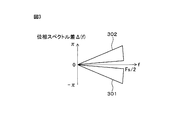
- FIG. 3 is a diagram illustrating an example of the relationship between the voice arrival direction and the phase spectrum difference ⁇ (f).
- the horizontal axis represents the frequency
- the vertical axis represents the phase spectrum difference.
- the phase spectrum difference range 301 is for each frequency in the case where sound coming from the first direction (in this embodiment, the direction in which the driver is located) is included in the first input sound signal and the second input sound signal. Represents the range of possible phase differences.
- the phase spectrum difference range 302 is obtained when the first input audio signal and the second input audio signal include audio coming from the second direction (in this embodiment, the direction in which the passenger is located). Represents the possible range of phase difference for each frequency.
- the microphone 11-2 is closer to the driver than the microphone 11-1. For this reason, the timing at which the sound produced by the driver reaches the microphone 11-1 is later than the timing at which the sound reaches the microphone 11-2. As a result, the phase of the sound emitted by the driver represented in the first frequency spectrum is delayed from the phase of the sound emitted by the driver represented in the second frequency spectrum. Therefore, the phase spectrum difference range 301 is located on the negative side. The range of the phase difference due to the delay becomes wider as the frequency is higher. Conversely, the microphone 11-1 is closer to the passenger than the microphone 11-2. For this reason, the timing at which the voice produced by the passenger reaches the microphone 11-2 is later than the timing at which the sound reaches the microphone 11-1.
- phase of the voice uttered by the passenger represented in the first frequency spectrum is ahead of the phase of the voice uttered by the fellow passenger represented in the second frequency spectrum. Therefore, the phase spectrum difference range 302 is located on the positive side. The range of the phase difference becomes wider as the frequency is higher.
- the directional sound generation unit 22 refers to the phase spectrum difference ⁇ (f) for each frame, and the phase difference for each frequency is included in the phase spectrum difference range 301 or included in the phase spectrum difference range 302. To determine whether or not Then, the directional sound generation unit 22 includes, for each frame, a frequency component whose phase difference is included in the phase spectrum difference range 301 in the first and second frequency spectra included in the sound coming from the first direction. It is determined that it is a component. Then, the directional sound generation unit 22 extracts a frequency component in which the phase difference is included in the phase spectrum difference range 301 from the first frequency spectrum for each frame to obtain a first directional sound spectrum.
- the directional sound generator 22 multiplies a frequency component whose phase difference is included in the phase spectrum difference range 301 by a gain of 1.
- the directional sound generation unit 22 multiplies a frequency component whose phase difference is out of the phase spectrum difference range 301 by a gain that becomes zero.
- the directional sound generator 22 generates the first directional sound spectrum.
- the directional sound generation unit 22 multiplies the frequency component deviating from the phase spectrum difference range 301 by a gain that decreases as the distance from the phase spectrum difference range 301 increases, and then includes the gain in the first directional sound spectrum. Also good.
- the directional sound generation unit 22 may extract a frequency component in which the phase difference is included in the phase spectrum difference range 301 from the second frequency spectrum for each frame to obtain the first directional sound spectrum.
- the directional sound generation unit 22 has a frequency component whose phase difference is included in the phase spectrum difference range 302 of the first and second frequency spectrums. It is determined that it is a component contained in. Then, the directional sound generation unit 22 extracts a frequency component whose phase difference is included in the phase spectrum difference range 302 from the first frequency spectrum for each frame to obtain a second directional sound spectrum. The directional sound generation unit 22 multiplies the frequency component that deviates from the phase spectrum difference range 302 by a gain that decreases as the distance from the phase spectrum difference range 302 increases, and then includes the gain in the second directional sound spectrum. Also good. Further, the directional sound generation unit 22 may extract a frequency component in which the phase difference is included in the phase spectrum difference range 302 from the second frequency spectrum for each frame to obtain the second directional sound spectrum.
- the directional speech generation unit 22 outputs the first directional speech spectrum and the second directional speech spectrum to the feature extraction unit 23 and the directional characteristic control unit 25 for each frame.
- the feature extraction unit 23 calculates, for each frame, a feature amount that represents the sound quality from the sound source for the frame based on the first and second directional speech spectra.
- the power of the first directional sound spectrum is increased to some extent because the sound from the first direction is increased for the frame including the sound emitted by the sound source (driver in this example) located in the first direction. Is done.
- the power of the second directional sound spectrum is Expected to be somewhat larger.
- the driver's voice power and the passenger's voice power change over time. Therefore, in the present embodiment, the feature extraction unit 23 uses, for each frame, the power and the power non-stationary degree (hereinafter, simply non-stationary) as the feature amount for each of the first and second directional speech spectra. (Referred to as the degree of nature).
- the feature extraction unit 23 calculates the power PX of the first directional speech spectrum and the power PY of the second directional speech spectrum for each frame according to the following equations.
- X (f) is the first directional speech spectrum for the frame of interest
- Y (f) is the second directional speech spectrum for the frame of interest.
- the feature extraction unit 23 calculates the non-stationarity degree RX of the first directional speech spectrum and the non-stationarity degree RY of the second directional speech spectrum for each frame according to the following equations.
- PX ′ represents the power of the first directional speech spectrum for the frame immediately before the frame of interest
- PY ′ represents the second directional speech spectrum for the frame immediately before the frame of interest. Represents the power of.
- the feature extraction unit 23 passes the calculated feature amount to the sound source direction determination unit 24 for each frame.
- the sound source direction determination unit 24 determines, for each frame, the first direction and the second direction in the frame based on the feature amount of the first directional speech spectrum and the feature amount of the second directional speech spectrum. The probability that only the sound source located in the second direction has uttered sound is determined. In the following, of the first direction and the second direction, the probability that only the sound source located in the second direction emits sound is the probability that only the sound source located in the second direction simply emits sound. Call it.
- the sound source direction determination unit 24 calculates, for each frame, the probability P that only the sound source located in the second direction emits sound according to the following equation.
- the sound source direction determination unit 24 notifies the directivity control unit 25 of the probability P that only the sound source located in the second direction has uttered sound for each frame.
- the directional characteristic control unit 25 forms an example of a directional sound output unit together with the frequency time conversion unit 26. Then, the directivity control unit 25 controls the directivity to be received for each frame according to the probability that only the sound source located in the second direction emits sound. In the present embodiment, the directional characteristic control unit 25 always outputs the first directional speech spectrum, and outputs the second directional speech spectrum multiplied by a gain representing the degree of suppression. The directivity control unit 25 controls the gain according to the probability P.
- the directivity control unit 25 compares the calculated probability P with at least one likelihood determination threshold for each frame. For example, when the probability P is higher than the first likelihood determination threshold value Th1 for the frame of interest, the directivity control unit 25 is likely to generate the sound only from the sound source located in the second direction in the frame. Is determined to be high. On the other hand, when the probability P is lower than the second likelihood determination threshold Th2 (where Th2 ⁇ Th1) for the frame of interest, the directivity control unit 25 only selects a sound source located in the second direction in the frame. It is determined that there is a low probability that the voice uttered.
- the sound source direction determination unit 24 uses the second direction in the frame. It is determined that the probability that only the sound source located at is uttered is medium.
- the directivity control unit 25 selects the first of the first directional sound spectrum and the second directional sound spectrum. Only the directional speech spectrum of is output. That is, the directivity control unit 25 limits the directivity to be received in the first direction by setting the gain to be multiplied by the second directional sound spectrum to 0.
- the directivity control unit 25 uses both the first directional sound spectrum and the second directional sound spectrum. Output. That is, the directivity control unit 25 sets the gain to be multiplied by the second directional speech spectrum to 1, thereby extending the directional characteristics for receiving sound not only in the first direction but also in the second direction.
- the directivity control unit 25 calculates the gain multiplied by the second directional sound spectrum, The probability P is determined so as to be closer to 1 as the value of the probability P increases.
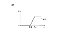
- FIG. 4 is a diagram showing an example of the relationship between the probability P that only the sound source located in the second direction has uttered sound and the gain G multiplied by the second directional sound spectrum.
- the horizontal axis represents the probability P
- the vertical axis represents the gain G.
- the graph 400 represents the relationship between the probability P and the gain.
- the gain G is set to zero. Further, when the probability P is equal to or greater than the first likelihood determination threshold Th1, the gain G is set to 1. When the probability P is greater than the second likelihood determination threshold Th2 and less than the first likelihood determination threshold Th1, the gain G increases monotonically and linearly as the probability P increases.
- one likelihood determination threshold Th may be used.
- the directivity control unit 25 determines the probability that only the sound source located in the second direction in the frame has emitted the sound. Is determined to be high.
- the directivity control unit 25 determines that the probability that only the sound source located in the second direction in the frame emits sound is low.
- the likelihood determination thresholds Th1, Th2, and Th may be set in advance by experiments or the like and stored in advance in a memory included in the voice processing device 13, for example.
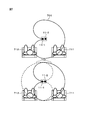
- FIG. 5 is a schematic diagram showing the directivity characteristics for sound reception.
- the range 501 in which the sensitivity to receive sound is high is that the driver 511 is positioned in the arrangement direction of the microphone 11-1 and the microphone 11-2. Set to the microphone 11-2 side.
- the range 502 in which the sensitivity to receive sound is high is the microphone 11 in the arrangement direction of the microphone 11-1 and the microphone 11-2. It is set on the microphone 11-1 side as well as the -2 side.
- the frequency time conversion unit 26 converts the first directional sound spectrum output from the directivity characteristic control unit 25 for each frame into a time domain signal by performing frequency time conversion, thereby providing a first directivity for each frame. Obtain an audio signal. Further, the frequency time conversion unit 26 converts the second directional sound spectrum output from the directivity characteristic control unit 25 into a time domain signal by frequency time conversion for each frame, thereby converting the second directional speech spectrum into a second signal for each frame. The directional sound signal is obtained. This frequency time conversion is an inverse conversion of the time frequency conversion performed by the time frequency conversion unit 21.
- the frequency-time conversion unit 26 adds the first directional audio signal by shifting the first directional audio signal for each successive frame in time order (that is, reproduction order) by 1 ⁇ 2 of the frame length. calculate. Similarly, the frequency time conversion unit 26 calculates the second directional sound signal by adding the second directional sound signal for each frame consecutive in time order while shifting the frame by 1 ⁇ 2 of the frame length. Then, the frequency time conversion unit 26 outputs the first directional sound signal and the second directional sound signal to other devices via the communication interface unit 14.
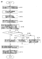
- FIG. 6 is an operation flowchart of audio processing executed by the audio processing device 13.
- the voice processing device 13 executes voice processing for each frame according to the following flowchart.
- the time-frequency converter 21 multiplies the first input audio signal and the second input audio signal divided in units of frames by a Hanning window function (step S101). Then, the time-frequency conversion unit 21 performs time-frequency conversion on the first input sound signal and the second input sound signal to calculate a first frequency spectrum and a second frequency spectrum (step S102).
- the directional sound generator 22 generates a first directional sound spectrum and a second directional sound spectrum based on the first and second frequency spectra (step S103).
- the feature extraction unit 23 calculates the power and non-stationarity degree of the first directional speech spectrum and the power and non-stationarity degree of the second directional speech spectrum as feature quantities representing the sound quality from the sound source (step S104).
- the sound source direction determination unit 24 is located in the second direction of the first and second directions based on the respective powers and unsteadiness levels of the first directional sound spectrum and the second directional sound spectrum.
- the probability P that the voice comes only from the sound source is calculated (step S105).
- the directivity control unit 25 determines whether or not the probability P is greater than the first likelihood determination threshold value Th1 (step S106). When the probability P is larger than the first likelihood determination threshold Th1 (step S106—Yes), the directivity control unit 25 outputs both the first and second directional speech spectra (step S107). On the other hand, when the probability P is equal to or less than the first likelihood determination threshold Th1 (No in step S106), the directivity control unit 25 determines whether or not the probability P is smaller than the second likelihood determination threshold Th2. Determination is made (step S108). When the probability P is smaller than the second likelihood determination threshold value Th2 (step S108—Yes), the directivity control unit 25 selects only the first directional speech spectrum from the first and second directional speech spectra.
- step S109 the directivity control unit 25 outputs a second directional sound spectrum whose amplitude is 0 over the entire frequency band together with the first directional sound spectrum.
- the directivity control unit 25 suppresses the second directional sound spectrum according to the probability P together with the first directional speech spectrum. Is output (step S110).
- the frequency time conversion unit 26 performs frequency time conversion on the first directional sound spectrum output from the directivity characteristic control unit 25 to calculate a first directional sound signal.
- the frequency time conversion unit 26 also performs frequency time conversion on the second directional sound spectrum to calculate a second directional sound signal (step S111). Then, the frequency time conversion unit 26 synthesizes the first directional sound signal of the current frame with a half frame length shift from the first directional sound signal up to the previous frame. Similarly, the frequency time conversion unit 26 synthesizes the second directional audio signal of the current frame by shifting the second directional audio signal up to the previous frame by a half frame length (step S112). Then, the voice processing device 13 ends the voice processing.
- this sound processing device has a first direction in which a sound source that is prioritized to receive sound is located, and a second direction in which another sound source is assumed to be located.
- the probability that only the sound source located in the second direction emits sound is calculated for each frame. If the probability is high, the speech processing apparatus not only includes the first directional speech signal including speech arriving from the first direction but also the second directional speech signal including speech arriving from the second direction. Is also output. That is, when the probability is high, the sound processing device controls the directivity characteristic of sound reception so that it includes not only the first direction but also the second direction. Thereby, for example, when the other speaker utters a voice while receiving a voice uttered by a specific speaker among a plurality of speakers preferentially, the other speaker It is also possible to receive voices emitted by.
- the feature extraction unit 23 calculates the power of the first directional speech spectrum and the power of the second directional speech spectrum as the feature amount representing the speech likeness from the sound source for each frame. It is not necessary to calculate the degree of unsteadiness. In this case, the feature extraction unit 23 may calculate the probability P according to the following equation.
- the directional sound generator 22 obtains the first directional sound spectrum and the second directional sound spectrum for each frame by synchronous subtraction between the first frequency spectrum and the second frequency spectrum. It may be calculated.
- the directional sound generation unit 22 calculates the first directional sound spectrum X (f) and the second directional sound spectrum Y (f) according to the following equation.
- N represents the total number of sampling points included in one frame, that is, the frame length.
- n represents a sampling time difference between the microphone 11-1 and the microphone 11-2 in which sound arrives from the sound source.
- the interval d between the microphone 11-1 and the microphone 11-2 is set to be (sound speed / Fs) or less so that n is 0 ⁇ n ⁇ 1, that is, the sampling interval or less.
- FIG. 7 is a schematic diagram showing directional characteristics for sound reception according to this modification.
- the range 701 in which the sensitivity to receive sound is high is such that the driver 711 is positioned in the arrangement direction of the microphone 11-1 and the microphone 11-2. Set to the microphone 11-2 side.
- the range 702 where the sensitivity to receive sound is high is the microphone 11-where the passenger 712 is located along with the microphone 11-2 side. Also set to 1 side.
- a range where the sensitivity for receiving the first directional audio signal is high overlaps with a part of the range where the sensitivity for receiving the second directional audio signal is high.
- the directivity control unit 25 may output a spectrum obtained by multiplying the first directional speech spectrum by the first gain representing the degree of suppression for each frame. Similarly, the directivity control unit 25 may output a spectrum obtained by multiplying the second directional speech spectrum by a second gain representing the degree of suppression for each frame. Then, the directivity control unit 25 adjusts the first gain and the second gain according to the elapsed time from the time when the degree of certainty that only the sound source located in the second direction emits sound has changed. May be.
- FIG. 8 is a diagram showing an example of the relationship between the elapsed time from the time when the degree of likelihood that only the sound source located in the second direction has uttered the sound and the first and second gains are changed.
- the horizontal axis represents time
- the vertical axis represents gain.
- a graph 801 represents the relationship between the first gain and the elapsed time from the time when the degree of likelihood that only the sound source located in the second direction has produced sound has changed.
- the graph 802 represents the relationship between the elapsed time from the time when the degree of likelihood that only the sound source located in the second direction has uttered the sound and the second gain are changed.
- the probability P that only the sound source located in the second direction emits sound is equal to or less than the first likelihood determination threshold Th1, and the probability P is the first likelihood at time t1.
- the degree determination threshold Th1 it is assumed that only the sound source located in the second direction has changed to a high degree of certainty that the sound has been emitted.
- the probability P that only the sound source located in the second direction emits sound is equal to or greater than the second likelihood determination threshold Th2, and the probability P is the second at time t3. It is assumed that it becomes smaller than the likelihood determination threshold Th2. That is, assume that at time t3, only the sound source located in the second direction has changed to a low probability of sound.
- the directivity control unit 25 outputs the first directional sound spectrum as it is until the probability that only the sound source located in the second direction has uttered the sound changes to high, and the second The directional speech spectrum of is not output.
- the directivity control unit 25 for a certain period (for example, several tens of milliseconds) until time t2 thereafter. 25 linearly monotonously decreases the first gain G1. Then, after time t2, the directivity control unit 25 sets the first gain G1 to a predetermined value (0.7 in this example) that satisfies 0 ⁇ G1 ⁇ 1. On the other hand, the directivity control unit 25 sets the second gain G2 to 1 after time t1. That is, the directivity control unit 25 attenuates and outputs the first directional sound spectrum, and outputs the second directional sound spectrum as it is. Thereby, while the sound is coming from the sound source located in the second direction, the noise received from the first direction for the sound from the second direction included in the second directional sound signal. The signal to noise ratio is improved.
- the directivity control unit 25 performs a certain period (for example, 100 msec) until time t4. ( ⁇ 200 msec) maintains the first gain G1 at a predetermined value. Then, the directivity control unit 25 returns the first gain G1 to 1 after time t4. Further, the directivity control unit 25 maintains the second gain G2 at 1 until time t4, and linearly monotonously decreases the second gain G2 after time t4. Then, the directivity control unit 25 sets the second gain G2 to 0 after time t5 after time t4.
- a certain period for example, 100 msec
- time t4 ⁇ 200 msec
- the second directional sound spectrum is output for a certain period thereafter. Therefore, for example, it is possible to prevent the rear end portion of the voice from the second direction included in the second directional voice signal, for example, the ending portion of the conversation voice uttered by the passenger located in the second direction from being interrupted. Is done. Therefore, for example, when another device that has received the second directional audio signal recognizes the fellow passenger's voice from the second directional audio signal, a reduction in recognition accuracy due to interruption of the ending portion is prevented.
- the period from time t3 to time t5 is equal to or longer than the period from time t3 to time t4, and is set to, for example, 100 msec to 300 msec.
- FIG. 9 is an operation flowchart of directivity control of the directivity control unit 25 according to this modification. Note that the directivity control process is executed instead of the processes in steps S106 to S110 in the operation flowchart of the audio process shown in FIG.
- P (t) the probability that only the sound source located in the second direction in the current frame emits sound
- P (t-1) the probability that only the sound source located in the second direction in the previous frame emits sound
- step S105 shown in FIG. 6 when the probability P (t) of the current frame is calculated, the directivity control unit 25 determines that the probability P (t) is larger than the first likelihood determination threshold Th1. Whether or not (step S201).
- the directivity control unit 25 determines that the probability P (t ⁇ 1) of the immediately preceding frame is the first likelihood. It is determined whether or not it is equal to or less than the degree determination threshold Th1 (step S202). If the probability P (t ⁇ 1) is equal to or less than the first likelihood determination threshold Th1 (step S202—Yes), it is highly likely that only the sound source located in the second direction emits sound in the current frame. Has changed.
- the directivity control unit 25 sets the number of frames cnt1 representing the elapsed time after the probability that only the sound source located in the second direction has emitted the sound has changed to 1 to 1.
- the directivity control unit 25 sets the number of frames cnt2 representing the elapsed time after the probability that only the sound source located in the second direction emits sound changes to low to 0 (step S203).
- the frame number cnt1 is set to 0 so that the first gain G1 is 1 and the second gain G2 is 0, and the frame number cnt2 is set during the period from time t3 to time t5. It is set to a value larger than the corresponding number of frames.
- the directivity control unit 25 increments the number of frames cnt1 by 1 (step S204). After step S203 or S204, the directivity control unit 25 sets the first gain G1 according to the number of frames cnt1 and sets the second gain G2 to 1, for example, as shown in FIG. (Step S205).
- the directivity control unit 25 determines that P (t) is the second likelihood determination. It is determined whether it is smaller than the threshold value Th2 (step S206). When P (t) is smaller than the second likelihood determination threshold value Th2 (step S206—Yes), the directivity control unit 25 determines that the probability P (t ⁇ 1) of the immediately preceding frame is the second likelihood determination. It is determined whether or not the threshold value is Th2 or more (step S207). If the probability P (t ⁇ 1) is greater than or equal to the second likelihood determination threshold Th2 (step S207—Yes), the probability that only the sound source located in the second direction has emitted sound is low in the current frame. Has changed. Therefore, the directivity control unit 25 sets the number of frames cnt1 to 0 and sets the number of frames cnt2 to 1 (step S208).
- the directivity control unit 25 increments the number of frames cnt2 by 1 (step S209). After step S208 or S209, the directivity control unit 25 sets the first gain G1 and the second gain G2 according to the number of frames cnt2 as shown in FIG. 8, for example (step S210). .
- step S206-No If P (t) is greater than or equal to the second likelihood determination threshold value Th2 in step S206 (step S206-No), the current frame continues to have a moderate probability. . Therefore, the directivity control unit 25 determines whether or not the number of frames cnt1 is greater than 0 (step S211). If the number of frames cnt1 is larger than 0 (step S211—Yes), it is considered that the state with high probability continues. Therefore, the directivity control unit 25 increments the number of frames cnt1 by 1 (step S204). On the other hand, if the number of frames cnt1 is 0 (No in step S211), the number of frames cnt2 should be larger than 0, so that it is considered that the state with low probability continues. Accordingly, the directivity control unit 25 increments the number of frames cnt2 by 1 (step S209).
- step S205 or step S210 the directivity control unit 25 multiplies the first directional speech spectrum by the first gain G1, and then outputs the first directional speech spectrum.
- the directivity control unit 25 multiplies the second directional speech spectrum by the second gain G2, and then outputs the second directional speech spectrum (step S212). Then, the audio processing device 13 executes the processing after step S111 in FIG.
- the sound processing device can improve the signal-to-noise ratio for the sound when only the sound source located in the second direction emits sound, and the sound source located in the second direction. It is possible to prevent the ending of the voice uttered from the voice from being interrupted.
- one likelihood determination threshold Th may be used instead of the two first likelihood determination thresholds Th1 and the second likelihood determination threshold Th2.
- the directivity control unit 25 synthesizes the first directional speech spectrum and the second directional speech spectrum that have been multiplied by the gain for each frame, and outputs the resultant as one spectrum. May be.
- the frequency time conversion unit 26 may calculate one directional sound signal by performing frequency time conversion on the one spectrum and synthesize it for each frame, and may output the directional sound signal. Alternatively, the frequency time conversion unit 26 may calculate one directional sound signal by combining the first directional sound signal and the second directional sound signal, and output the directional sound signal.
- the voice processing device may be implemented in a device other than the voice input device as described above, for example, a telephone conference system.
- a computer program that causes a computer to realize the functions of the sound processing apparatus according to the above-described embodiment or modification may be provided in a form recorded on a computer-readable medium such as a magnetic recording medium or an optical recording medium. .
- FIG. 10 is a configuration diagram of a computer that operates as a sound processing apparatus by operating a computer program that realizes the functions of the respective units of the sound processing apparatus according to the above-described embodiment or its modification.
- the computer 100 includes a user interface unit 101, an audio interface unit 102, a communication interface unit 103, a storage unit 104, a storage medium access device 105, and a processor 106.
- the processor 106 is connected to the user interface unit 101, the audio interface unit 102, the communication interface unit 103, the storage unit 104, and the storage medium access device 105 via, for example, a bus.
- the user interface unit 101 includes, for example, an input device such as a keyboard and a mouse, and a display device such as a liquid crystal display.
- the user interface unit 101 may include a device such as a touch panel display in which an input device and a display device are integrated.
- the user interface unit 101 outputs an operation signal for starting audio processing to the processor 106 in response to a user operation.
- the audio interface unit 102 has an interface circuit for connecting the computer 100 to a microphone (not shown). Then, the audio interface unit 102 passes the input audio signal received from each of the two or more microphones to the processor 106.
- the communication interface unit 103 includes a communication interface for connecting to a communication network in accordance with a communication standard such as Ethernet (registered trademark) and its control circuit. Then, for example, the communication interface unit 103 outputs each of the first directional audio signal and the second directional audio signal received from the processor 106 to another device via the communication network. Alternatively, the communication interface unit 103 outputs the voice recognition result obtained by applying the voice recognition process to the first directional voice signal and the second directional voice signal to another device via the communication network. May be. Alternatively, the communication interface unit 103 may output a signal generated by an application executed according to the voice recognition result to another device via the communication network.
- a communication standard such as Ethernet (registered trademark) and its control circuit. Then, for example, the communication interface unit 103 outputs each of the first directional audio signal and the second directional audio signal received from the processor 106 to another device via the communication network. Alternatively, the communication interface unit 103 outputs the voice recognition result obtained by applying the voice recognition process to the first directional voice
- the storage unit 104 includes, for example, a readable / writable semiconductor memory and a read-only semiconductor memory.
- the storage unit 104 stores a computer program executed on the processor 106 for executing voice processing, various data used in the voice processing, various signals generated during the voice processing, and the like. .
- the storage medium access device 105 is a device that accesses a storage medium 107 such as a magnetic disk, a semiconductor memory card, and an optical storage medium.
- the storage medium access device 105 reads, for example, a computer program for voice processing executed on the processor 106 and stored in the storage medium 107, and passes it to the processor 106.
- the processor 106 generates a first directional sound signal and a second directional sound signal from each input sound signal by executing the sound processing computer program according to the above-described embodiment or modification. Then, the processor 106 outputs the first directional audio signal and the second directional audio signal to the communication interface unit 103.
- the processor 106 may recognize a voice uttered by a speaker located in the first direction by executing a voice recognition process on the first directional voice signal. Similarly, the processor 106 may recognize a voice uttered by another speaker located in the second direction by performing a voice recognition process on the second directional voice signal. The processor 106 may execute a predetermined application in accordance with each voice recognition result.
- a computer program for voice processing for causing a computer to execute the above.
- Appendix 2 The computer program for audio processing according to appendix 1, wherein controlling the output of the second directional audio signal outputs the second directional audio signal for a frame whose probability is higher than a first threshold value.
- Appendix 3 Controlling the output of the second directional sound signal means that the probability in the first frame is less than a second threshold value that is lower than the first threshold value, and the frame immediately before the first frame.
- Controlling the output of the second directional audio signal is from the third frame to the third frame when the likelihood in a third frame after the second frame is less than the second threshold.
- the computer is further configured to calculate the power of the first directional audio signal and the power of the second directional audio signal based on the first frequency spectrum and the second frequency spectrum. , The calculating the probability calculates the probability based on a power ratio of the power of the second directional audio signal to the power of the first directional audio signal for each frame.
- a first voice input unit for generating a first voice signal representing the collected voice
- a second voice input unit that is arranged at a different position from the first voice input unit and generates a second voice signal representing the collected voice
- a time-frequency converter that converts the first audio signal and the second audio signal into a first frequency spectrum and a second frequency spectrum in a frequency domain for each frame having a predetermined time length; For each frame, based on the first frequency spectrum and the second frequency spectrum, the first of the first direction that is prioritized to receive sound and the second direction different from the first direction.
- a sound source direction determination unit that calculates the probability that only a sound source located in the direction of 2 has produced a sound; For each frame, a first directional speech signal including speech arriving from the first direction calculated based on the first frequency spectrum and the second frequency spectrum is output, and according to the probability. Then, a directional sound output for controlling whether or not to output a second directional sound signal including sound coming from the second direction calculated based on the first frequency spectrum and the second frequency spectrum And A speech processing apparatus.
Landscapes
- Health & Medical Sciences (AREA)
- Otolaryngology (AREA)
- Physics & Mathematics (AREA)
- Engineering & Computer Science (AREA)
- Acoustics & Sound (AREA)
- Signal Processing (AREA)
- General Health & Medical Sciences (AREA)
- Circuit For Audible Band Transducer (AREA)
- Obtaining Desirable Characteristics In Audible-Bandwidth Transducers (AREA)
Abstract
【課題】優先する方向に位置する音源からの音声だけでなく、他の方向に位置する他の音源からの音声も抑圧せずに出力できる音声処理用コンピュータプログラムを提供する。 【解決手段】音声処理用コンピュータプログラムは、第1の音声入力部により生成された第1の音声信号と第2の音声入力部により生成された第2の音声信号とを、所定の時間長を持つフレームごとに周波数領域の第1の周波数スペクトル及び第2の周波数スペクトルに変換し、フレームごとに、第1及び第2の周波数スペクトルに基づいて、第1の方向及び第2の方向のうちの第2の方向に位置する音源のみが音声を発した確からしさを算出し、フレームごとに、第1の方向から到来する音声を含む第1の指向音声信号を出力するとともに、確からしさに応じて、第2の方向から到来する音声を含む第2の指向音声信号を出力するか否かを制御することをコンピュータに実行させるための命令を含む。
Description
本発明は、例えば、複数のマイクロホンを用いて集音された音声を含む音声信号を処理する音声処理用コンピュータプログラム、音声処理装置及び音声処理方法に関する。
近年、複数のマイクロホンにより音声を集音することで得られた音声信号を処理する音声処理装置が開発されている。このような音声処理装置において、音声信号に含まれる特定方向からの音声を聞き取り易くするために、その音声信号においてその特定方向以外からの音声を抑圧する技術が研究されている(例えば、特許文献1及び2を参照)。
場合によっては、特定方向に位置する音源からの音声だけでなく、他の方向に位置する他の音源からの音声についても、抑圧しないことが好ましいことがある。しかし、例えば、特許文献1に記載された技術では、特定方向以外の方向から到来する音声は抑圧されてしまう。一方、例えば、特許文献2に記載された技術では、特定方向に位置する音源からの音声だけでなく、想定される他の方向に位置する他の音源からの音声も抑圧しないようにすると、抑圧対象とならない方向の範囲が広過ぎて、雑音の抑圧が不十分となる。その結果として、特定方向に位置する音源からの音声の聞き取り易さが十分に向上しない可能性がある。
一つの側面では、本発明は、優先する方向に位置する音源からの音声だけでなく、他の方向に位置する他の音源からの音声も抑圧せずに出力できる音声処理用コンピュータプログラムを提供することを目的とする。
一つの実施形態によれば、音声処理用コンピュータプログラムが提供される。この音声処理用コンピュータプログラムは、第1の音声入力部により生成された第1の音声信号、及び、第1の音声入力部と異なる位置に配置された第2の音声入力部により生成された第2の音声信号を、それぞれ、所定の時間長を持つフレームごとに周波数領域の第1の周波数スペクトル及び第2の周波数スペクトルに変換し、フレームごとに、第1の周波数スペクトル及び第2の周波数スペクトルに基づいて、受音することが優先される第1の方向及び第1の方向と異なる第2の方向のうちの第2の方向に位置する音源のみが音声を発したる確からしさを算出し、フレームごとに、第1の周波数スペクトル及び第2の周波数スペクトルに基づいて算出される第1の方向から到来する音声を含む第1の指向音声信号を出力するとともに、確からしさに応じて、第1の周波数スペクトル及び第2の周波数スペクトルに基づいて算出される第2の方向から到来する音声を含む第2の指向音声信号を出力するか否かを制御する、ことをコンピュータに実行させるための命令を含む。
一つの側面では、優先する方向に位置する音源からの音声だけでなく、他の方向に位置する他の音源からの音声も抑圧せずに出力できる。
以下、図を参照しつつ、音声処理装置について説明する。この音声処理装置は、複数の音声入力部により得られた音声信号において、フレームごとに、優先される音源が位置する第1の方向と、他の音源が位置することが想定される第2の方向のうち、第2の方向に位置する音源のみが音声を発した確からしさを算出する。そしてこの音声処理装置は、その確からしさが高いフレームについて、第1の方向から到来する音声を含む第1の指向音声信号だけでなく、第2の方向から到来する音声を含む第2の指向音声信号も出力する。すなわち、この音声処理装置は、その確からしさが高いときに、受音する方向を一時的に第2の方向を含むように拡張する。
図1は、一つの実施形態による音声処理装置が実装された音声入力装置の概略構成図である。音声入力装置1は、二つのマイクロホン11-1、11-2と、二つのアナログ/デジタル変換器12-1、12-2と、音声処理装置13と、通信インターフェース部14とを有する。音声入力装置1は、例えば、車両(図示せず)に搭載され、ドライバあるいは他の同乗者が発した音声を集音し、その音声を含む音声信号をナビゲーションシステム(図示せず)あるいはハンズフリーホン(図示せず)等へ出力する。そして音声処理装置13は、ドライバが位置する方向以外からの音声を抑圧するような受音の指向特性を設定する。さらに、音声処理装置13は、ドライバが位置する方向(第1の方向)と同乗者が位置する方向(第2の方向)のうち、同乗者のみが音声を発した確からしさが高い場合には、第2の方向から到来する音声も抑圧しないように指向特性を変化させる。
マイクロホン11-1、11-2は、それぞれ、音声入力部の一例である。マイクロホン11-1及びマイクロホン11-2は、例えば、集音対象とする音源であるドライバと、他の音源である、助手席にいる同乗者(以下、単に同乗者と呼ぶ)との間において、例えば、インストルメントパネル、あるいは、車室内の天井付近に配置される。本実施形態では、マイクロホン11-1の方がマイクロホン11-2よりも同乗者に近く、かつ、マイクロホン11-2の方がマイクロホン11-1よりもドライバの近くに位置するように、マイクロホン11-1及びマイクロホン11-2は配置される。そしてマイクロホン11-1が周囲の音声を集音することにより生成したアナログの入力音声信号はアナログ/デジタル変換器12-1に入力される。同様に、マイクロホン11-2が周囲の音声を集音することにより生成したアナログの入力音声信号はアナログ/デジタル変換器12-2に入力される。
アナログ/デジタル変換器12-1は、マイクロホン11-1から受け取ったアナログの入力音声信号を所定のサンプリング周波数でサンプリングすることによりデジタル化された入力音声信号を生成する。同様に、アナログ/デジタル変換器12-2は、マイクロホン11-2から受け取ったアナログの入力音声信号を所定のサンプリング周波数でサンプリングすることによりデジタル化された入力音声信号を生成する。
なお、以下では、説明の便宜上、マイクロホン11-1が集音することで生成され、アナログ/デジタル変換器12-1によりデジタル化された入力音声信号を第1の入力音声信号と呼ぶ。また、マイクロホン11-2が集音することで生成され、アナログ/デジタル変換器12-2によりデジタル化された入力音声信号を第2の入力音声信号と呼ぶ。
アナログ/デジタル変換器12-1は、第1の入力音声信号を音声処理装置13へ出力する。同様に、アナログ/デジタル変換器12-2は、第2の入力音声信号を音声処理装置13へ出力する。
アナログ/デジタル変換器12-1は、第1の入力音声信号を音声処理装置13へ出力する。同様に、アナログ/デジタル変換器12-2は、第2の入力音声信号を音声処理装置13へ出力する。
音声処理装置13は、例えば、一つまたは複数のプロセッサと、メモリとを有する。そして音声処理装置13は、受信した第1の入力音声信号と第2の入力音声信号とから、制御される指向特性に応じて受音する方向以外の方向から到来した雑音を抑圧した指向音声信号を生成する。そして音声処理装置13は、通信インターフェース部14を介して、その指向音声信号をナビゲーションシステム(図示せず)あるいはハンズフリーホン(図示せず)といった他の機器へ出力する。
通信インターフェース部14は、所定の通信規格に従って音声入力装置1を他の機器と接続するための通信インターフェース回路などを含む。例えば、通信インターフェース回路は、例えば、Bluetooth(登録商標)といった、音声信号の通信に利用可能な近距離無線通信規格に従って動作する回路、あるいは、universal serial bus(USB)といったシリアルバス規格に従って動作する回路とすることができる。そして通信インターフェース部14は、音声処理装置13から受け取った出力音声信号を他の機器へ出力する。
図2は、一つの実施形態による音声処理装置13の概略構成図である。音声処理装置13は、時間周波数変換部21と、指向音声生成部22と、特徴抽出部23と、音源方向判定部24と、指向特性制御部25と、周波数時間変換部26とを有する。音声処理装置13が有するこれらの各部は、例えば、音声処理装置13が有するプロセッサ上で実行されるコンピュータプログラムによって実現される機能モジュールとして実装される。あるいは、音声処理装置13が有するこれらの各部は、音声処理装置13が有するプロセッサとは別個に、それらの各部の機能を実現する一つまたは複数の集積回路として音声処理装置13に実装されてもよい。
時間周波数変換部21は、第1の入力音声信号及び第2の入力音声信号のそれぞれについて、フレーム単位で時間領域から周波数領域へ変換することにより、複数の周波数のそれぞれについての振幅成分と位相成分とを含む周波数スペクトルを算出する。なお、時間周波数変換部21は、第1の入力音声信号と第2の入力音声信号のそれぞれに対して同じ処理を行えばよいので、以下では、第1の入力音声信号についての処理について説明する。
本実施形態では、時間周波数変換部21は、第1の入力音声信号を、所定のフレーム長(例えば、数10msec)を持つフレームごとに分割する。その際、時間周波数変換部21は、例えば、連続する二つのフレームがフレーム長の1/2だけずれるように各フレームを設定する。
時間周波数変換部21は、各フレームに対して窓処理を実行する。すなわち、時間周波数変換部21は、各フレームに所定の窓関数を乗じる。例えば、時間周波数変換部21は、窓関数としてハニング窓を用いることができる。
時間周波数変換部21は、窓処理が施されたフレームを受け取る度に、そのフレームを時間領域から周波数領域へ変換することにより、複数の周波数のそれぞれについての振幅成分と位相成分とを含む周波数スペクトルを算出する。時間周波数変換部21は、例えば、フレームに対して、高速フーリエ変換(Fast Fourier Transform, FFT)といった時間周波数変換を実行することにより周波数スペクトルを算出すればよい。なお、以下では、便宜上、第1の入力音声信号について得られた周波数スペクトルを第1の周波数スペクトルと呼び、第2の入力音声信号について得られた周波数スペクトルを第2の周波数スペクトルと呼ぶ。
時間周波数変換部21は、フレームごとに、第1の周波数スペクトル及び第2の周波数スペクトルを指向音声生成部22へ出力する。
指向音声生成部22は、フレームごとに、マイクロホン11-1及び11-2から見て、受音することが優先される第1の方向(本実施形態では、ドライバが位置する方向)から到来する音声の周波数スペクトルを表す第1の指向音声スペクトルを生成する。また指向音声生成部22は、フレームごとに、マイクロホン11-1及び11-2から見て、他の音源が位置すると想定される第2の方向(本実施形態では、同乗者が位置する方向)から到来する音声の周波数スペクトルを表す第2の指向音声スペクトルを生成する。
先ず、指向音声生成部22は、例えば、フレームごとに、周波数ごとの第1の周波数スペクトルと第2の周波数スペクトル間の位相差を求める。この位相差は、そのフレームにおいて音声が到来した方向に応じて変化するので、この位相差は、音声が到来した方向を特定するために利用できる。例えば、位相差算出部12は、次式に従って周波数ごとの位相差を表す位相スペクトル差Δθ(f)を求める。

ただし、IN1(f)は、第1の周波数スペクトルを表し、IN2(f)は、第2の周波数スペクトルを表す。そしてfは周波数を表す。またFsは、アナログ/デジタル変換器12-1及び12-2におけるサンプリング周波数を表す。
図3は、音声の到来方向と位相スペクトル差Δθ(f)の関係の一例を示す図である。図3において、横軸は周波数を表し、縦軸は位相スペクトル差を表す。そして位相スペクトル差の範囲301は、第1の方向(本実施形態では、ドライバが位置する方向)から到来する音声が第1の入力音声信号及び第2の入力音声信号に含まれる場合の周波数ごとの位相差の取り得る範囲を表す。一方、位相スペクトル差の範囲302は、第2の方向(本実施形態では、同乗者が位置する方向)から到来する音声が第1の入力音声信号及び第2の入力音声信号に含まれる場合の周波数ごとの位相差の取り得る範囲を表す。
ドライバに対して、マイクロホン11-2の方がマイクロホン11-1よりも近い。そのため、ドライバが発した音声がマイクロホン11-1に到達するタイミングがマイクロホン11-2に到達するタイミングよりも遅くなる。その結果として、第1の周波数スペクトルに表されるドライバが発した音声の位相は、第2の周波数スペクトルに表されるドライバが発した音声の位相よりも遅れる。そのため、位相スペクトル差の範囲301は、負側に位置する。そしてその遅れによる位相差の範囲は、周波数が高いほど広くなる。逆に、同乗者に対して、マイクロホン11-1の方がマイクロホン11-2よりも近い。そのため、同乗者が発した音声がマイクロホン11-2に到達するタイミングがマイクロホン11-1に到達するタイミングよりも遅くなる。その結果として、第1の周波数スペクトルに表される同乗者が発した音声の位相は、第2の周波数スペクトルに表される同乗者が発した音声の位相よりも進む。そのため、位相スペクトル差の範囲302は、正側に位置する。そして位相差の範囲は、周波数が高いほど広くなる。
そこで、指向音声生成部22は、各フレームについて、位相スペクトル差Δθ(f)を参照して、周波数ごとに位相差が位相スペクトル差の範囲301に含まれるか、位相スペクトル差の範囲302に含まれるかを判定する。そして指向音声生成部22は、各フレームについて、第1及び第2の周波数スペクトルのうち、位相差が位相スペクトル差の範囲301に含まれる周波数の成分は、第1の方向から到来した音声に含まれる成分であると判定する。そして指向音声生成部22は、各フレームについて、第1の周波数スペクトルから、位相差が位相スペクトル差の範囲301に含まれる周波数の成分を抽出して第1の指向音声スペクトルとする。すなわち、指向音声生成部22は、位相差が位相スペクトル差の範囲301に含まれる周波数の成分に対して1となるゲインを乗じる。一方、指向音声生成部22は、位相差が位相スペクトル差の範囲301から外れる周波数の成分に対して0となるゲインを乗じる。これにより、指向音声生成部22は、第1の指向音声スペクトルを生成する。なお、指向音声生成部22は、位相スペクトル差の範囲301から外れる周波数の成分に対して、位相スペクトル差の範囲301から遠くなるほど小さくなるゲインを乗じてから、第1の指向音声スペクトルに含めてもよい。また、指向音声生成部22は、各フレームについて、第2の周波数スペクトルから、位相差が位相スペクトル差の範囲301に含まれる周波数の成分を抽出して第1の指向音声スペクトルとしてもよい。
同様に、指向音声生成部22は、各フレームについて、第1及び第2の周波数スペクトルのうち、位相差が位相スペクトル差の範囲302に含まれる周波数の成分は、第2の方向から到来した音声に含まれる成分であると判定する。そして指向音声生成部22は、各フレームについて、第1の周波数スペクトルから、位相差が位相スペクトル差の範囲302に含まれる周波数の成分を抽出して第2の指向音声スペクトルとする。なお、指向音声生成部22は、位相スペクトル差の範囲302から外れる周波数の成分に対して、位相スペクトル差の範囲302から遠くなるほど小さくなるゲインを乗じてから、第2の指向音声スペクトルに含めてもよい。また、指向音声生成部22は、各フレームについて、第2の周波数スペクトルから、位相差が位相スペクトル差の範囲302に含まれる周波数の成分を抽出して第2の指向音声スペクトルとしてもよい。
指向音声生成部22は、フレームごとに、第1の指向音声スペクトル及び第2の指向音声スペクトルのそれぞれを特徴抽出部23及び指向特性制御部25へ出力する。
特徴抽出部23は、フレームごとに、第1及び第2の指向音声スペクトルに基づいて、そのフレームについて音源からの音声らしさを表す特徴量を算出する。
第1の方向に位置する音源(この例では、ドライバ)が発した音声が含まれるフレームについて、第1の方向からの音声が大きくなるので、第1の指向音声スペクトルのパワーはある程度大きくなると想定される。同様に、第2の方向に位置する音源(この例では、同乗者)が発した音声が含まれるフレームについて、第2の方向からの音声が大きくなるので、第2の指向音声スペクトルのパワーはある程度大きくなると想定される。また、ドライバの音声のパワー及び同乗者の音声のパワーは経時変化すると想定される。そこで、本実施形態では、特徴抽出部23は、フレームごとに、第1及び第2の指向音声スペクトルのそれぞれについて、特徴量として、パワーと、パワーについての非定常性度合い(以下、単に非定常性度と呼ぶ)とを算出する。
例えば、特徴抽出部23は、次式に従って、フレームごとに、第1の指向音声スペクトルのパワーPX及び第2の指向音声スペクトルのパワーPYを算出する。
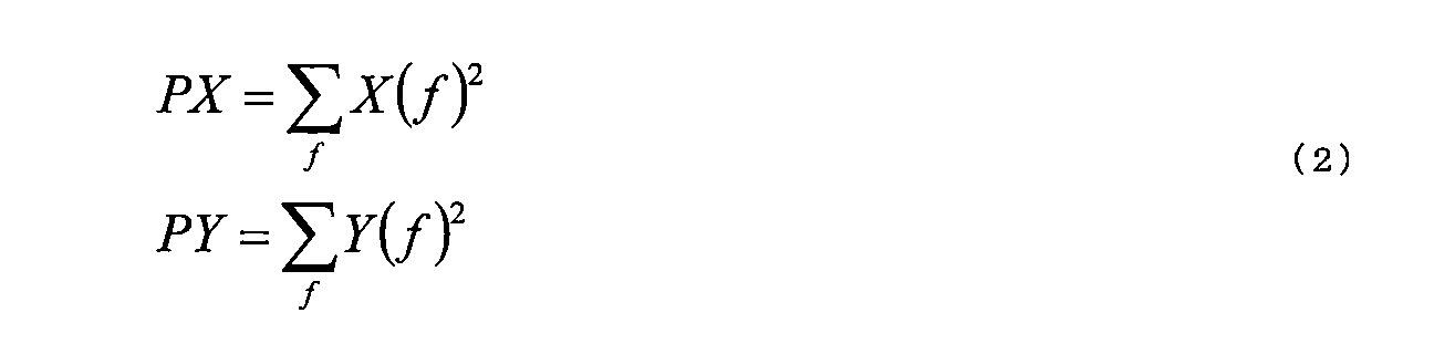
ここで、X(f)は、着目するフレームについての第1の指向音声スペクトルであり、Y(f)は、着目するフレームについての第2の指向音声スペクトルである。
また、特徴抽出部23は、次式に従って、フレームごとに、第1の指向音声スペクトルの非定常性度RX及び第2の指向音声スペクトルの非定常性度RYを算出する。

ここで、PX'は、着目するフレームの一つ前のフレームについての第1の指向音声スペクトルのパワーを表し、PY'は、着目するフレームの一つ前のフレームについての第2の指向音声スペクトルのパワーを表す。特徴抽出部23は、フレームごとに、算出した特徴量を音源方向判定部24へわたす。
音源方向判定部24は、フレームごとに、第1の指向音声スペクトルの特徴量と第2の指向音声スペクトルの特徴量とに基づいて、そのフレームにおいて、第1の方向と第2の方向のうち、第2の方向に位置する音源のみが音声を発した確からしさを判定する。以下では、第1の方向と第2の方向のうち、第2の方向に位置する音源のみが音声を発した確からしさを、単に第2の方向に位置する音源のみが音声を発した確からしさと呼ぶ。
上記のように、第1の方向に位置する音源が発した音声が含まれるフレームについて、第1の指向音声スペクトルのパワー及び非定常性度はある程度大きくなると想定される。一方、第2の方向に位置する音源が発した音声が含まれるフレームについて、第2の指向音声スペクトルのパワー及び非定常性度はある程度大きくなると想定される。したがって、音源方向判定部24は、フレームごとに、第2の方向に位置する音源のみが音声を発した確からしさPを、次式に従って算出する。
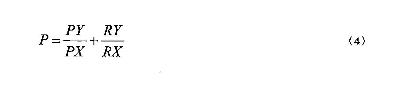
したがって、確からしさPの値が大きいほど、第1の方向及び第2の方向のうち、第2の方向に位置する音源のみが音声を発している可能性が高い。音源方向判定部24は、フレームごとに、第2の方向に位置する音源のみが音声を発した確からしさPを、指向特性制御部25へ通知する。
指向特性制御部25は、周波数時間変換部26とともに、指向音声出力部の一例を形成する。そして指向特性制御部25は、フレームごとに、第2の方向に位置する音源のみが音声を発した確からしさに応じて、受音する指向特性を制御する。本実施形態では、指向特性制御部25は、第1の指向音声スペクトルを常に出力し、第2の指向音声スペクトルには抑圧の程度を表すゲインを乗じて出力する。そして指向特性制御部25は、そのゲインを、確からしさPに応じて制御する。
本実施形態では、指向特性制御部25は、フレームごとに、算出した確からしさPを少なくとも一つの尤度判定閾値と比較する。例えば、指向特性制御部25は、着目するフレームについて、確からしさPが第1の尤度判定閾値Th1よりも高い場合、そのフレームにおいて第2の方向に位置する音源のみが音声を発した確からしさが高いと判定する。一方、指向特性制御部25は、着目するフレームについて、確からしさPが第2の尤度判定閾値Th2(ただし、Th2<Th1)よりも低い場合、そのフレームにおいて第2の方向に位置する音源のみが音声を発した確からしさは低いと判定する。また、着目するフレームについて、確からしさPが第2の尤度判定閾値Th2以上、かづ、第1の尤度判定閾値Th1以下であれば、音源方向判定部24は、そのフレームにおいて第2の方向に位置する音源のみが音声を発した確からしさは中程度であると判定する。
着目するフレームについて、第2の方向に位置する音源のみが音声を発した確からしさが低い場合、指向特性制御部25は、第1の指向音声スペクトル及び第2の指向音声スペクトルのうち、第1の指向音声スペクトルのみを出力する。すなわち、指向特性制御部25は、第2の指向音声スペクトルに乗じるゲインを0に設定することで、受音する指向特性を第1の方向に制限する。一方、着目するフレームについて、第2の方向に位置する音源のみが音声を発した確からしさが高い場合、指向特性制御部25は、第1の指向音声スペクトル及び第2の指向音声スペクトルの両方を出力する。すなわち、指向特性制御部25は、第2の指向音声スペクトルに乗じるゲインを1に設定することで、受音する指向特性を、第1の方向だけでなく、第2の方向にも拡張する。
また、着目するフレームについて、第2の方向に位置する音源のみが音声を発した確からしさの程度が中程度である場合、指向特性制御部25は、第2の指向音声スペクトルに乗じるゲインを、確からしさPの値が高くなるほど1に近くなるように決定する。
図4は、第2の方向に位置する音源のみが音声を発した確からしさPと第2の指向音声スペクトルに乗じるゲインGとの関係の一例を示す図である。図4において、横軸は確からしさPを表し、縦軸は、ゲインGを表す。そしてグラフ400は、確からしさPとゲインの関係を表す。
グラフ400に示されるように、確からしさPが第2の尤度判定閾値Th2以下である場合、ゲインGは0に設定される。また、確からしさPが第1の尤度判定閾値Th1以上である場合、ゲインGは1に設定される。そして確からしさPが第2の尤度判定閾値Th2よりも大きく、かつ、第1の尤度判定閾値Th1未満である場合、確からしさPが高くなるにつれてゲインGも単調かつ線形に高くなる。
なお、変形例によれば、一つの尤度判定閾値Thが用いられてもよい。この場合には、着目するフレームについて、確からしさPが尤度判定閾値Thよりも高い場合、指向特性制御部25は、そのフレームにおいて第2の方向に位置する音源のみが音声を発した確からしさが高いと判定する。一方、確からしさPが尤度判定閾値Th以下である場合、指向特性制御部25は、そのフレームにおいて第2の方向に位置する音源のみが音声を発した確からしさが低いと判定する。
なお、尤度判定閾値Th1、Th2、Thは、例えば、実験などにより予め設定され、音声処理装置13が有するメモリに予め保存されればよい。
図5は、受音についての指向特性を表す模式図である。第2の方向に位置する音源のみが音声を発した確からしさの程度が低い場合、受音する感度が高い範囲501は、マイクロホン11-1とマイクロホン11-2の並び方向について、ドライバ511が位置するマイクロホン11-2側に設定される。一方、第2の方向に位置する音源のみが音声を発した確からしさの程度が高い場合、受音する感度が高い範囲502は、マイクロホン11-1とマイクロホン11-2の並び方向について、マイクロホン11-2側とともに、マイクロホン11-1側にも設定される。これにより、ドライバ511が位置する方向だけでなく、同乗者512が位置する方向も受音する感度が高い範囲に含まれる。
周波数時間変換部26は、フレームごとに、指向特性制御部25から出力された第1の指向音声スペクトルを、周波数時間変換して時間領域の信号に変換することにより、フレームごとの第1の指向音声信号を得る。また、周波数時間変換部26は、フレームごとに、指向特性制御部25から出力された第2の指向音声スペクトルを、周波数時間変換して時間領域の信号に変換することにより、フレームごとの第2の指向音声信号を得る。なお、この周波数時間変換は、時間周波数変換部21により行われる時間周波数変換の逆変換である。
周波数時間変換部26は、時間順(すなわち、再生順)に連続するフレームごとの第1の指向音声信号を、フレーム長の1/2ずつずらして加算することにより、第1の指向音声信号を算出する。同様に、周波数時間変換部26は、時間順に連続するフレームごとの第2の指向音声信号を、フレーム長の1/2ずつずらして加算することにより、第2の指向音声信号を算出する。そして周波数時間変換部26は、第1の指向音声信号及び第2の指向音声信号を、通信インターフェース部14を介して他の機器へ出力する。
図6は、音声処理装置13により実行される音声処理の動作フローチャートである。音声処理装置13は、フレームごとに、下記のフローチャートに従って音声処理を実行する。
時間周波数変換部21は、フレーム単位に分割された第1の入力音声信号及び第2の入力音声信号にハニング窓関数を乗じる(ステップS101)。そして、時間周波数変換部21は、第1の入力音声信号及び第2の入力音声信号を時間周波数変換して第1の周波数スペクトル及び第2の周波数スペクトルを算出する(ステップS102)。
指向音声生成部22は、第1及び第2の周波数スペクトルに基づいて、第1の指向音声スペクトル及び第2の指向音声スペクトルを生成する(ステップS103)。特徴抽出部23は、音源からの音声らしさを表す特徴量として、第1の指向音声スペクトルのパワー及び非定常性度と、第2の指向音声スペクトルのパワー及び非定常性度を算出する(ステップS104)。
音源方向判定部24は、第1の指向音声スペクトル及び第2の指向音声スペクトルのそれぞれのパワー及び非定常性度に基づいて、第1及び第2の方向のうち、第2の方向に位置する音源のみから音声が到来する確からしさPを算出する(ステップS105)。
指向特性制御部25は、確からしさPが第1の尤度判定閾値Th1よりも大きいか否か判定する(ステップS106)。確からしさPが第1の尤度判定閾値Th1より大きい場合(ステップS106-Yes)、指向特性制御部25は、第1及び第2の指向音声スペクトルの両方を出力する(ステップS107)。一方、確からしさPが第1の尤度判定閾値Th1以下である場合(ステップS106-No)、指向特性制御部25は、確からしさPが第2の尤度判定閾値Th2よりも小さいか否か判定する(ステップS108)。確からしさPが第2の尤度判定閾値Th2よりも小さい場合(ステップS108-Yes)、指向特性制御部25は、第1及び第2の指向音声スペクトルのうちの第1の指向音声スペクトルのみを出力する(ステップS109)。すなわち、指向特性制御部25は、第1の指向音声スペクトルとともに、振幅が全周波数帯域にわたって0となる第2の指向音声スペクトルを出力する。一方、確からしさPが第2の尤度判定閾値Th2以上である場合(ステップS108-No)、指向特性制御部25は、第1の指向音声スペクトルとともに、確からしさPに応じて抑圧した第2の指向音声スペクトルを出力する(ステップS110)。
周波数時間変換部26は、指向特性制御部25から出力された第1の指向音声スペクトルを周波数時間変換して第1の指向音声信号を算出する。また周波数時間変換部26は、第2の指向音声スペクトルが出力された場合には、第2の指向音声スペクトルについても周波数時間変換して第2の指向音声信号を算出する(ステップS111)。そして周波数時間変換部26は、前フレームまでの第1の指向音声信号に対して半フレーム長ずらして現フレームの第1の指向音声信号を合成する。同様に、周波数時間変換部26は、前フレームまでの第2の指向音声信号に対して半フレーム長ずらして現フレームの第2の指向音声信号を合成する(ステップS112)。そして音声処理装置13は、音声処理を終了する。
以上に説明してきたように、この音声処理装置は、受音することが優先される音源が位置する第1の方向と、他の音源が位置することが想定される第2の方向のうちの第2の方向に位置する音源のみが音声を発した確からしさをフレームごとに算出する。そしてこの音声処理装置は、その確からしさが高いと、第1の方向から到来する音声を含む第1の指向音声信号だけでなく、第2の方向から到来する音声を含む第2の指向音声信号も出力する。すなわち、この音声処理装置は、その確からしさが高いと、受音の指向特性を、第1の方向だけでなく、第2の方向も含むように制御する。これにより、この音声処理装置は、例えば、複数の話者のうちの特定の話者が発した音声を優先的に受音しつつ、他の話者が音声を発したときには、他の話者が発した音声も受音することを可能とする。
なお、変形例によれば、特徴抽出部23は、フレームごとに、音源からの音声らしさを表す特徴量として、第1の指向音声スペクトルのパワーと、第2の指向音声スペクトルのパワーを算出し、非定常性度については算出しなくてもよい。この場合には、特徴抽出部23は、確からしさPを、次式に従って算出すればよい。

また他の変形例によれば、指向音声生成部22は、第1の周波数スペクトルと第2の周波数スペクトル間の同期減算により、フレームごとに第1の指向音声スペクトル及び第2の指向音声スペクトルを算出してもよい。この場合、指向音声生成部22は、次式に従って第1の指向音声スペクトルX(f)及び第2の指向音声スペクトルY(f)を算出する。

ここで、Nは、1フレームに含まれるサンプリング点の総数、すなわち、フレーム長を表す。またnは、マイクロホン11-1とマイクロホン11-2間の、音源から音声が到達するサンプリング時間差を表す。なお、nが0<n≦1、すなわち、サンプリング間隔以下となるように、マイクロホン11-1とマイクロホン11-2間の間隔dは、(音速/Fs)以下となるように設定される。
図7は、この変形例による、受音についての指向特性を表す模式図である。第2の方向に位置する音源のみが音声を発した確からしさの程度が低い場合、受音する感度が高い範囲701は、マイクロホン11-1とマイクロホン11-2の並び方向について、ドライバ711が位置するマイクロホン11-2側に設定される。一方、第2の方向に位置する音源のみが音声を発した確からしさの程度が高い場合、受音する感度が高い範囲702は、マイクロホン11-2側とともに、同乗者712が位置するマイクロホン11-1側にも設定される。またこの例では、第1の指向音声信号について受音する感度が高い範囲と、第2の指向音声信号について受音する感度が高い範囲の一部が重なる。
さらに他の変形例によれば、指向特性制御部25は、フレームごとに、第1の指向音声スペクトルに抑圧の程度を表す第1のゲインを乗じて得られるスペクトルを出力してもよい。同様に、指向特性制御部25は、フレームごとに、第2の指向音声スペクトルに抑圧の程度を表す第2のゲインを乗じて得られるスペクトルを出力してもよい。そして指向特性制御部25は、第2の方向に位置する音源のみが音声を発した確からしさの程度が変化した時点からの経過時間に応じて、第1のゲイン及び第2のゲインを調節してもよい。
図8は、第2の方向に位置する音源のみが音声を発した確からしさの程度が変化した時点からの経過時間と第1及び第2のゲインの関係の一例を示す図である。図8において、横軸は時間を表し、縦軸はゲインを表す。そしてグラフ801は、第2の方向に位置する音源のみが音声を発した確からしさの程度が変化した時点からの経過時間と第1のゲインの関係を表す。またグラフ802は、第2の方向に位置する音源のみが音声を発した確からしさの程度が変化した時点からの経過時間と第2のゲインの関係を表す。
この例では、時刻t1までは、第2の方向に位置する音源のみが音声を発した確からしさPが第1の尤度判定閾値Th1以下であり、時刻t1において確からしさPが第1の尤度判定閾値Th1より大きくなったとする。すなわち、時刻t1において、第2の方向に位置する音源のみが音声を発した確からしさの程度が高いに変化したとする。また、時刻t1以降、時刻t3までは、第2の方向に位置する音源のみが音声を発した確からしさPは第2の尤度判定閾値Th2以上であり、時刻t3において確からしさPが第2の尤度判定閾値Th2より小さくなったとする。すなわち、時刻t3において、第2の方向に位置する音源のみが音声を発した確からしさの程度が低いに変化したとする。
この場合、時刻t1までは、第1のゲインG1は1に設定され、一方、第2のゲインG2は0に設定される。すなわち、第2の方向に位置する音源のみが音声を発した確からしさの程度が高いに変化するまでは、指向特性制御部25は、第1の指向音声スペクトルをそのまま出力し、かつ、第2の指向音声スペクトルを出力しない。
一方、時刻t1になり、第2の方向に位置する音源のみが音声を発した確からしさの程度が高いに変化すると、その後の時刻t2までの一定期間(例えば、数10msec)、指向特性制御部25は、第1のゲインG1を線形に単調減少させる。そして時刻t2以降、指向特性制御部25は、第1のゲインG1を、0<G1<1となる所定の値(この例では、0.7)に設定する。一方、指向特性制御部25は、時刻t1以降、第2のゲインG2を1に設定する。すなわち、指向特性制御部25は、第1の指向音声スペクトルを減衰させて出力し、かつ、第2の指向音声スペクトルをそのまま出力する。これにより、第2の方向に位置する音源から音声が到来している間は、第2の指向音声信号に含まれる、第2の方向からの音声についての、第1の方向から受音した雑音に対する信号対雑音比が向上する。
また、時刻t3になり、第2の方向に位置する音源のみが音声を発した確からしさの程度が低いに変化すると、指向特性制御部25は、その後の時刻t4までの一定期間(例えば、100msec~200msec)は第1のゲインG1を所定値に維持する。そして指向特性制御部25は、時刻t4以降、第1のゲインG1を1に戻す。また、指向特性制御部25は、時刻t4まで、第2のゲインG2を1に維持し、時刻t4以降、第2のゲインG2を線形に単調減少させる。そして指向特性制御部25は、時刻t4よりも後の時刻t5以降、第2のゲインG2を0にする。これにより、第2の方向に位置する音源のみが音声を発した確からしさの程度が低いに変化しても、その後の一定期間の間、第2の指向音声スペクトルは出力される。そのため、例えば、第2の指向音声信号に含まれる、第2の方向からの音声の後端部分、例えば、第2の方向に位置する同乗者が発した会話音声の語尾部分が途切れることが防止される。したがって、例えば、第2の指向音声信号を受信した他の機器が、第2の指向音声信号から同乗者の音声を認識する場合、語尾部分が途切れることによる認識精度の低下が防止される。なお、時刻t3~時刻t5までの期間は、時刻t3~時刻t4までの期間以上であり、かつ、例えば、100msec~300msecに設定される。
図9は、この変形例による指向特性制御部25の指向特性制御の動作フローチャートである。なお、この指向特性制御の処理は、図6に示される音声処理の動作フローチャートにおけるステップS106~S110までの処理の代わりに実行される。また図9では、現フレームにおける、第2の方向に位置する音源のみが音声を発した確からしさをP(t)と表記し、直前のフレームにおける、第2の方向に位置する音源のみが音声を発した確からしさをP(t-1)と表記する。
図6に示されたステップS105において、現フレームの確からしさP(t)が算出されると、指向特性制御部25は、確からしさP(t)が第1の尤度判定閾値Th1よりも大きいか否か判定する(ステップS201)。確からしさP(t)が第1の尤度判定閾値Th1よりも大きい場合(ステップS201-Yes)、指向特性制御部25は、直前のフレームの確からしさP(t-1)が第1の尤度判定閾値Th1以下か否か判定する(ステップS202)。確からしさP(t-1)が第1の尤度判定閾値Th1以下であれば(ステップS202-Yes)、現フレームにおいて、第2の方向に位置する音源のみが音声を発した確からしさが高いに変化している。そこで、指向特性制御部25は、第2の方向に位置する音源のみが音声を発した確からしさが高いに変化してからの経過時間を表すフレーム数cnt1を1に設定する。また、指向特性制御部25は、第2の方向に位置する音源のみが音声を発した確からしさが低いに変化してからの経過時間を表すフレーム数cnt2を0に設定する(ステップS203)。なお、初期状態では、第1のゲインG1が1、第2のゲインG2が0となるように、フレーム数cnt1は0に設定され、かつ、フレーム数cnt2は、時刻t3~時刻t5の期間に相当するフレーム数よりも大きい値に設定される。
一方、確からしさP(t-1)が第1の尤度判定閾値Th1よりも高ければ(ステップS202-No)、直前のフレームの時点でも、第2の方向に位置する音源のみが音声を発した確からしさが高く、その確からしさが高い状態が現フレームまで継続している。そのため、指向特性制御部25は、フレーム数cnt1を1インクリメントする(ステップS204)。そしてステップS203またはS204の後、指向特性制御部25は、第1のゲインG1を、例えば、図8に示されるように、フレーム数cnt1に応じて設定し、第2のゲインG2を1に設定する(ステップS205)。
また、ステップS201において、確からしさP(t)が第1の尤度判定閾値Th1以下である場合(ステップS201-No)、指向特性制御部25は、P(t)が第2の尤度判定閾値Th2よりも小さいか否か判定する(ステップS206)。P(t)が第2の尤度判定閾値Th2よりも小さい場合(ステップS206-Yes)、指向特性制御部25は、直前のフレームの確からしさP(t-1)が第2の尤度判定閾値Th2以上か否か判定する(ステップS207)。確からしさP(t-1)が第2の尤度判定閾値Th2以上であれば(ステップS207-Yes)、現フレームにおいて、第2の方向に位置する音源のみが音声を発した確からしさが低いに変化している。そこで、指向特性制御部25は、フレーム数cnt1を0に設定し、かつ、フレーム数cnt2を1に設定する(ステップS208)。
一方、確からしさP(t-1)が第2の尤度判定閾値Th2よりも低ければ(ステップS207-No)、直前のフレームの時点でも、第2の方向に位置する音源のみが音声を発した確からしさが低く、その確からしさが低い状態が現フレームまで継続している。そのため、指向特性制御部25は、フレーム数cnt2を1インクリメントする(ステップS209)。そしてステップS208またはS209の後、指向特性制御部25は、第1のゲインG1及び第2のゲインG2を、例えば、図8に示されるように、フレーム数cnt2に応じて設定する(ステップS210)。
また、ステップS206にて、P(t)が第2の尤度判定閾値Th2以上である場合(ステップS206-No)、現フレームでは、確からしさが中程度の状態であることが継続している。そこで、指向特性制御部25は、フレーム数cnt1が0よりも大きいか否か判定する(ステップS211)。フレーム数cnt1が0よりも大きければ(ステップS211-Yes)、確からしさが高い状態が継続しているとみなす。そこで指向特性制御部25は、フレーム数cnt1を1インクリメントする(ステップS204)。一方、フレーム数cnt1が0であれば(ステップS211-No)、フレーム数cnt2が0よりも大きいはずなので、確からしさが低い状態が継続しているとみなす。そこで指向特性制御部25は、フレーム数cnt2を1インクリメントする(ステップS209)。
ステップS205またはステップS210の後、指向特性制御部25は、第1のゲインG1を第1の指向音声スペクトルに乗じてからその第1の指向音声スペクトルを出力する。また、指向特性制御部25は、第2のゲインG2を第2の指向音声スペクトルに乗じてからその第2の指向音声スペクトルを出力する(ステップS212)。そして音声処理装置13は、図6のステップS111以降の処理を実行する。
この変形例によれば、音声処理装置は、第2の方向に位置する音源のみが音声を発している場合のその音声についての信号対雑音比を向上できるとともに、第2の方向に位置する音源から発した音声の語尾が途切れることを防止できる。なお、この変形例においても、二つの第1の尤度判定閾値Th1と第2の尤度判定閾値Th2の代わりに、一つの尤度判定閾値Thが用いられてもよい。この場合には、指向特性制御部25は、図9に示された動作フローチャートにおいて、Th1=Th2=Thとして、指向特性制御を行えばよい。
上記の実施形態または変形例において、指向特性制御部25は、フレームごとに、ゲインが乗じられた後の第1の指向音声スペクトルと第2の指向音声スペクトルを合成して一つのスペクトルとしてから出力してもよい。そして周波数時間変換部26は、その一つのスペクトルを周波数時間変換してフレームごとに合成することで、一つの指向音声信号を算出し、その指向音声信号を出力してもよい。あるいは、周波数時間変換部26は、第1の指向音声信号と第2の指向音声信号を合成して一つの指向音声信号を算出し、その指向音声信号を出力してもよい。
上記の実施形態または変形例による音声処理装置は、上記のような音声入力装置以外の装置、例えば、電話会議システムなどに実装されてもよい。
上記の実施形態または変形例による音声処理装置が有する各機能をコンピュータに実現させるコンピュータプログラムは、磁気記録媒体あるいは光記録媒体といった、コンピュータによって読み取り可能な媒体に記録された形で提供されてもよい。
図10は、上記の実施形態またはその変形例による音声処理装置の各部の機能を実現するコンピュータプログラムが動作することにより、音声処理装置として動作するコンピュータの構成図である。
コンピュータ100は、ユーザインターフェース部101と、オーディオインターフェース部102と、通信インターフェース部103と、記憶部104と、記憶媒体アクセス装置105と、プロセッサ106とを有する。プロセッサ106は、ユーザインターフェース部101、オーディオインターフェース部102、通信インターフェース部103、記憶部104及び記憶媒体アクセス装置105と、例えば、バスを介して接続される。
コンピュータ100は、ユーザインターフェース部101と、オーディオインターフェース部102と、通信インターフェース部103と、記憶部104と、記憶媒体アクセス装置105と、プロセッサ106とを有する。プロセッサ106は、ユーザインターフェース部101、オーディオインターフェース部102、通信インターフェース部103、記憶部104及び記憶媒体アクセス装置105と、例えば、バスを介して接続される。
ユーザインターフェース部101は、例えば、キーボードとマウスなどの入力装置と、液晶ディスプレイといった表示装置とを有する。または、ユーザインターフェース部101は、タッチパネルディスプレイといった、入力装置と表示装置とが一体化された装置を有してもよい。そしてユーザインターフェース部101は、例えば、ユーザの操作に応じて、音声処理を開始させる操作信号をプロセッサ106へ出力する。
オーディオインターフェース部102は、コンピュータ100を、マイクロホン(図示せず)と接続するためのインターフェース回路を有する。そしてオーディオインターフェース部102は、2以上のマイクロホンのそれぞれから受け取った入力音声信号をプロセッサ106へ渡す。
通信インターフェース部103は、イーサネット(登録商標)などの通信規格に従った通信ネットワークに接続するための通信インターフェース及びその制御回路を有する。そして通信インターフェース部103は、例えば、プロセッサ106から受け取った、第1の指向音声信号及び第2の指向音声信号のそれぞれを通信ネットワークを介して他の機器へ出力する。あるいは、通信インターフェース部103は、第1の指向音声信号及び第2の指向音声信号に対して音声認識処理を適用することで得られた音声認識結果を、通信ネットワークを介して他の機器へ出力してもよい。あるいはまた、通信インターフェース部103は、音声認識結果に応じて実行されたアプリケーションにより生成された信号を、通信ネットワークを介して他の機器へ出力してもよい。
記憶部104は、例えば、読み書き可能な半導体メモリと読み出し専用の半導体メモリとを有する。そして記憶部104は、プロセッサ106上で実行される、音声処理を実行するためのコンピュータプログラム、及び音声処理で利用される様々なデータまたは音声処理の途中で生成される各種の信号などを記憶する。
記憶媒体アクセス装置105は、例えば、磁気ディスク、半導体メモリカード及び光記憶媒体といった記憶媒体107にアクセスする装置である。記憶媒体アクセス装置105は、例えば、記憶媒体107に記憶された、プロセッサ106上で実行される音声処理用のコンピュータプログラムを読み込み、プロセッサ106に渡す。
プロセッサ106は、上記の実施形態または変形例による音声処理用コンピュータプログラムを実行することにより、各入力音声信号から第1の指向音声信号及び第2の指向音声信号を生成する。そしてプロセッサ106は、第1の指向音声信号及び第2の指向音声信号を通信インターフェース部103へ出力する。
さらに、プロセッサ106は、第1の指向音声信号に対して音声認識処理を実行することで、第1の方向に位置する話者が発した音声を認識してもよい。同様に、プロセッサ106は、第2の指向音声信号に対して音声認識処理を実行することで、第2の方向に位置する他の話者が発した音声を認識してもよい。そしてプロセッサ106は、それぞれの音声認識結果に応じて所定のアプリケーションを実行してもよい。
ここに挙げられた全ての例及び特定の用語は、読者が、本発明及び当該技術の促進に対する本発明者により寄与された概念を理解することを助ける、教示的な目的において意図されたものであり、本発明の優位性及び劣等性を示すことに関する、本明細書の如何なる例の構成、そのような特定の挙げられた例及び条件に限定しないように解釈されるべきものである。本発明の実施形態は詳細に説明されているが、本発明の精神及び範囲から外れることなく、様々な変更、置換及び修正をこれに加えることが可能であることを理解されたい。
以上説明した実施形態及びその変形例に関し、更に以下の付記を開示する。
(付記1)
第1の音声入力部により生成された第1の音声信号、及び、前記第1の音声入力部と異なる位置に配置された第2の音声入力部により生成された第2の音声信号を、それぞれ、所定の時間長を持つフレームごとに周波数領域の第1の周波数スペクトル及び第2の周波数スペクトルに変換し、
フレームごとに、前記第1の周波数スペクトル及び前記第2の周波数スペクトルに基づいて、受音することが優先される第1の方向及び前記第1の方向と異なる第2の方向のうちの前記第2の方向に位置する音源のみが音声を発した確からしさを算出し、
フレームごとに、前記第1の周波数スペクトル及び前記第2の周波数スペクトルに基づいて算出される前記第1の方向から到来する音声を含む第1の指向音声信号を出力するとともに、前記確からしさに応じて、前記第1の周波数スペクトル及び前記第2の周波数スペクトルに基づいて算出される前記第2の方向から到来する音声を含む第2の指向音声信号を出力するか否かを制御する、
ことをコンピュータに実行させるための音声処理用コンピュータプログラム。
(付記2)
前記第2の指向音声信号の出力を制御することは、前記確からしさが第1の閾値よりも高くなるフレームについて前記第2の指向音声信号を出力する、付記1に記載の音声処理用コンピュータプログラム。
(付記3)
前記第2の指向音声信号の出力を制御することは、第1のフレームにおける前記確からしさが前記第1の閾値よりも低い第2の閾値未満となり、かつ、前記第1のフレームの直前のフレームにおける前記確からしさが前記第2の閾値以上である場合、前記第1のフレームから第1の期間経過後のフレームから前記第2の指向音声信号の出力を停止する、付記2に記載の音声処理用コンピュータプログラム。
(付記4)
前記第2の指向音声信号の出力を制御することは、第2のフレームにおける前記確からしさが前記第1の閾値よりも高く、かつ、前記第2のフレームの直前のフレームにおける前記確からしさが前記第1の閾値以下である場合、前記第2のフレームから第2の期間にわたって前記第1の指向音声信号を抑圧して出力する、付記3に記載の音声処理用コンピュータプログラム。
(付記5)
前記第2の指向音声信号の出力を制御することは、前記第2のフレーム以降の第3のフレームにおける前記確からしさが前記第2の閾値未満となる場合、前記第3のフレームから第3の期間経過した時点を前記第2の期間の終端とする、付記4に記載の音声処理用コンピュータプログラム。
(付記6)
フレームごとに、前記第1の周波数スペクトル及び前記第2の周波数スペクトルに基づいて、前記第1の指向音声信号のパワー及び前記第2の指向音声信号のパワーを算出することをさらにコンピュータに実行させ、
前記確からしさを算出することは、フレームごとに、前記第1の指向音声信号のパワーに対する前記第2の指向音声信号のパワーのパワー比に基づいて前記確からしさを算出する、付記1~5の何れかに記載の音声処理用コンピュータプログラム。
(付記7)
フレームごとに、前記第1の周波数スペクトル及び前記第2の周波数スペクトルに基づいて、前記第1の指向音声の非定常性度合い及び前記第2の指向音声の非定常性度合いを算出することをさらにコンピュータに実行させ、
前記確からしさを算出することは、フレームごとに、前記第1の指向音声の非定常性度合いに対する前記第2の指向音声の非定常性度合いの非定常度比と前記パワー比の和に基づいて前記確からしさを算出する、付記6に記載の音声処理用コンピュータプログラム。
(付記8)
集音した音声を表す第1の音声信号を生成する第1の音声入力部と、
前記第1の音声入力部と異なる位置に配置され、集音した音声を表す第2の音声信号を生成する第2の音声入力部と、
前記第1の音声信号及び第2の音声信号を、それぞれ、所定の時間長を持つフレームごとに周波数領域の第1の周波数スペクトル及び第2の周波数スペクトルに変換する時間周波数変換部と、
フレームごとに、前記第1の周波数スペクトル及び前記第2の周波数スペクトルに基づいて、受音することが優先される第1の方向及び前記第1の方向と異なる第2の方向のうちの前記第2の方向に位置する音源のみが音声を発した確からしさを算出する音源方向判定部と、
フレームごとに、前記第1の周波数スペクトル及び前記第2の周波数スペクトルに基づいて算出される前記第1の方向から到来する音声を含む第1の指向音声信号を出力するとともに、前記確からしさに応じて、前記第1の周波数スペクトル及び前記第2の周波数スペクトルに基づいて算出される前記第2の方向から到来する音声を含む第2の指向音声信号を出力するか否かを制御する指向音声出力部と、
を有する音声処理装置。
(付記9)
第1の音声入力部により生成された第1の音声信号、及び、前記第1の音声入力部と異なる位置に配置された第2の音声入力部により生成された第2の音声信号を、それぞれ、所定の時間長を持つフレームごとに周波数領域の第1の周波数スペクトル及び第2の周波数スペクトルに変換し、
フレームごとに、前記第1の周波数スペクトル及び前記第2の周波数スペクトルに基づいて、受音することが優先される第1の方向及び前記第1の方向と異なる第2の方向のうちの前記第2の方向に位置する音源のみが音声を発した確からしさを算出し、
フレームごとに、前記第1の周波数スペクトル及び前記第2の周波数スペクトルに基づいて算出される前記第1の方向から到来する音声を含む第1の指向音声信号を出力するとともに、前記確からしさに応じて、前記第1の周波数スペクトル及び前記第2の周波数スペクトルに基づいて算出される前記第2の方向から到来する音声を含む第2の指向音声信号を出力するか否かを制御する、
ことを含む音声処理方法。
(付記1)
第1の音声入力部により生成された第1の音声信号、及び、前記第1の音声入力部と異なる位置に配置された第2の音声入力部により生成された第2の音声信号を、それぞれ、所定の時間長を持つフレームごとに周波数領域の第1の周波数スペクトル及び第2の周波数スペクトルに変換し、
フレームごとに、前記第1の周波数スペクトル及び前記第2の周波数スペクトルに基づいて、受音することが優先される第1の方向及び前記第1の方向と異なる第2の方向のうちの前記第2の方向に位置する音源のみが音声を発した確からしさを算出し、
フレームごとに、前記第1の周波数スペクトル及び前記第2の周波数スペクトルに基づいて算出される前記第1の方向から到来する音声を含む第1の指向音声信号を出力するとともに、前記確からしさに応じて、前記第1の周波数スペクトル及び前記第2の周波数スペクトルに基づいて算出される前記第2の方向から到来する音声を含む第2の指向音声信号を出力するか否かを制御する、
ことをコンピュータに実行させるための音声処理用コンピュータプログラム。
(付記2)
前記第2の指向音声信号の出力を制御することは、前記確からしさが第1の閾値よりも高くなるフレームについて前記第2の指向音声信号を出力する、付記1に記載の音声処理用コンピュータプログラム。
(付記3)
前記第2の指向音声信号の出力を制御することは、第1のフレームにおける前記確からしさが前記第1の閾値よりも低い第2の閾値未満となり、かつ、前記第1のフレームの直前のフレームにおける前記確からしさが前記第2の閾値以上である場合、前記第1のフレームから第1の期間経過後のフレームから前記第2の指向音声信号の出力を停止する、付記2に記載の音声処理用コンピュータプログラム。
(付記4)
前記第2の指向音声信号の出力を制御することは、第2のフレームにおける前記確からしさが前記第1の閾値よりも高く、かつ、前記第2のフレームの直前のフレームにおける前記確からしさが前記第1の閾値以下である場合、前記第2のフレームから第2の期間にわたって前記第1の指向音声信号を抑圧して出力する、付記3に記載の音声処理用コンピュータプログラム。
(付記5)
前記第2の指向音声信号の出力を制御することは、前記第2のフレーム以降の第3のフレームにおける前記確からしさが前記第2の閾値未満となる場合、前記第3のフレームから第3の期間経過した時点を前記第2の期間の終端とする、付記4に記載の音声処理用コンピュータプログラム。
(付記6)
フレームごとに、前記第1の周波数スペクトル及び前記第2の周波数スペクトルに基づいて、前記第1の指向音声信号のパワー及び前記第2の指向音声信号のパワーを算出することをさらにコンピュータに実行させ、
前記確からしさを算出することは、フレームごとに、前記第1の指向音声信号のパワーに対する前記第2の指向音声信号のパワーのパワー比に基づいて前記確からしさを算出する、付記1~5の何れかに記載の音声処理用コンピュータプログラム。
(付記7)
フレームごとに、前記第1の周波数スペクトル及び前記第2の周波数スペクトルに基づいて、前記第1の指向音声の非定常性度合い及び前記第2の指向音声の非定常性度合いを算出することをさらにコンピュータに実行させ、
前記確からしさを算出することは、フレームごとに、前記第1の指向音声の非定常性度合いに対する前記第2の指向音声の非定常性度合いの非定常度比と前記パワー比の和に基づいて前記確からしさを算出する、付記6に記載の音声処理用コンピュータプログラム。
(付記8)
集音した音声を表す第1の音声信号を生成する第1の音声入力部と、
前記第1の音声入力部と異なる位置に配置され、集音した音声を表す第2の音声信号を生成する第2の音声入力部と、
前記第1の音声信号及び第2の音声信号を、それぞれ、所定の時間長を持つフレームごとに周波数領域の第1の周波数スペクトル及び第2の周波数スペクトルに変換する時間周波数変換部と、
フレームごとに、前記第1の周波数スペクトル及び前記第2の周波数スペクトルに基づいて、受音することが優先される第1の方向及び前記第1の方向と異なる第2の方向のうちの前記第2の方向に位置する音源のみが音声を発した確からしさを算出する音源方向判定部と、
フレームごとに、前記第1の周波数スペクトル及び前記第2の周波数スペクトルに基づいて算出される前記第1の方向から到来する音声を含む第1の指向音声信号を出力するとともに、前記確からしさに応じて、前記第1の周波数スペクトル及び前記第2の周波数スペクトルに基づいて算出される前記第2の方向から到来する音声を含む第2の指向音声信号を出力するか否かを制御する指向音声出力部と、
を有する音声処理装置。
(付記9)
第1の音声入力部により生成された第1の音声信号、及び、前記第1の音声入力部と異なる位置に配置された第2の音声入力部により生成された第2の音声信号を、それぞれ、所定の時間長を持つフレームごとに周波数領域の第1の周波数スペクトル及び第2の周波数スペクトルに変換し、
フレームごとに、前記第1の周波数スペクトル及び前記第2の周波数スペクトルに基づいて、受音することが優先される第1の方向及び前記第1の方向と異なる第2の方向のうちの前記第2の方向に位置する音源のみが音声を発した確からしさを算出し、
フレームごとに、前記第1の周波数スペクトル及び前記第2の周波数スペクトルに基づいて算出される前記第1の方向から到来する音声を含む第1の指向音声信号を出力するとともに、前記確からしさに応じて、前記第1の周波数スペクトル及び前記第2の周波数スペクトルに基づいて算出される前記第2の方向から到来する音声を含む第2の指向音声信号を出力するか否かを制御する、
ことを含む音声処理方法。
1 音声入力装置
11-1、11-2 マイクロホン
12-1、12-2 アナログ/デジタル変換器
13 音声処理装置
14 通信インターフェース部
21 時間周波数変換部
22 指向音声生成部
23 特徴抽出部
24 音源方向判定部
25 指向特性制御部
26 周波数時間変換部
100 コンピュータ
101 ユーザインターフェース部
102 オーディオインターフェース部
103 通信インターフェース部
104 記憶部
105 記憶媒体アクセス装置
106 プロセッサ
107 記憶媒体
11-1、11-2 マイクロホン
12-1、12-2 アナログ/デジタル変換器
13 音声処理装置
14 通信インターフェース部
21 時間周波数変換部
22 指向音声生成部
23 特徴抽出部
24 音源方向判定部
25 指向特性制御部
26 周波数時間変換部
100 コンピュータ
101 ユーザインターフェース部
102 オーディオインターフェース部
103 通信インターフェース部
104 記憶部
105 記憶媒体アクセス装置
106 プロセッサ
107 記憶媒体
Claims (9)
- 第1の音声入力部により生成された第1の音声信号、及び、前記第1の音声入力部と異なる位置に配置された第2の音声入力部により生成された第2の音声信号を、それぞれ、所定の時間長を持つフレームごとに周波数領域の第1の周波数スペクトル及び第2の周波数スペクトルに変換し、
フレームごとに、前記第1の周波数スペクトル及び前記第2の周波数スペクトルに基づいて、受音することが優先される第1の方向及び前記第1の方向と異なる第2の方向のうちの前記第2の方向に位置する音源のみが音声を発した確からしさを算出し、
フレームごとに、前記第1の周波数スペクトル及び前記第2の周波数スペクトルに基づいて算出される前記第1の方向から到来する音声を含む第1の指向音声信号を出力するとともに、前記確からしさに応じて、前記第1の周波数スペクトル及び前記第2の周波数スペクトルに基づいて算出される前記第2の方向から到来する音声を含む第2の指向音声信号を出力するか否かを制御する、
ことをコンピュータに実行させるための音声処理用コンピュータプログラム。 - 前記第2の指向音声信号の出力を制御することは、前記確からしさが第1の閾値よりも高くなるフレームについて前記第2の指向音声信号を出力する、請求項1に記載の音声処理用コンピュータプログラム。
- 前記第2の指向音声信号の出力を制御することは、第1のフレームにおける前記確からしさが前記第1の閾値よりも低い第2の閾値未満となり、かつ、前記第1のフレームの直前のフレームにおける前記確からしさが前記第2の閾値以上である場合、前記第1のフレームから第1の期間経過後のフレームから前記第2の指向音声信号の出力を停止する、請求項2に記載の音声処理用コンピュータプログラム。
- 前記第2の指向音声信号の出力を制御することは、第2のフレームにおける前記確からしさが前記第1の閾値よりも高く、かつ、前記第2のフレームの直前のフレームにおける前記確からしさが前記第1の閾値以下である場合、前記第2のフレームから第2の期間にわたって前記第1の指向音声信号を抑圧して出力する、請求項3に記載の音声処理用コンピュータプログラム。
- 前記第2の指向音声信号の出力を制御することは、前記第2のフレーム以降の第3のフレームにおける前記確からしさが前記第2の閾値未満となる場合、前記第3のフレームから第3の期間経過した時点を前記第2の期間の終端とする、請求項4に記載の音声処理用コンピュータプログラム。
- フレームごとに、前記第1の周波数スペクトル及び前記第2の周波数スペクトルに基づいて、前記第1の指向音声信号のパワー及び前記第2の指向音声信号のパワーを算出することをさらにコンピュータに実行させ、
前記確からしさを算出することは、フレームごとに、前記第1の指向音声信号のパワーに対する前記第2の指向音声信号のパワーのパワー比に基づいて前記確からしさを算出する、請求項1~5の何れかに記載の音声処理用コンピュータプログラム。 - フレームごとに、前記第1の周波数スペクトル及び前記第2の周波数スペクトルに基づいて、前記第1の指向音声の非定常性度合い及び前記第2の指向音声の非定常性度合いを算出することをさらにコンピュータに実行させ、
前記確からしさを算出することは、フレームごとに、前記第1の指向音声の非定常性度合いに対する前記第2の指向音声の非定常性度合いの非定常度比と前記パワー比の和に基づいて前記確からしさを算出する、請求項6に記載の音声処理用コンピュータプログラム。 - 集音した音声を表す第1の音声信号を生成する第1の音声入力部と、
前記第1の音声入力部と異なる位置に配置され、集音した音声を表す第2の音声信号を生成する第2の音声入力部と、
前記第1の音声信号及び第2の音声信号を、それぞれ、所定の時間長を持つフレームごとに周波数領域の第1の周波数スペクトル及び第2の周波数スペクトルに変換する時間周波数変換部と、
フレームごとに、前記第1の周波数スペクトル及び前記第2の周波数スペクトルに基づいて、受音することが優先される第1の方向及び前記第1の方向と異なる第2の方向のうちの前記第2の方向に位置する音源のみが音声を発した確からしさを算出する音源方向判定部と、
フレームごとに、前記第1の周波数スペクトル及び前記第2の周波数スペクトルに基づいて算出される前記第1の方向から到来する音声を含む第1の指向音声信号を出力するとともに、前記確からしさに応じて、前記第1の周波数スペクトル及び前記第2の周波数スペクトルに基づいて算出される前記第2の方向から到来する音声を含む第2の指向音声信号を出力するか否かを制御する指向音声出力部と、
を有する音声処理装置。 - 第1の音声入力部により生成された第1の音声信号、及び、前記第1の音声入力部と異なる位置に配置された第2の音声入力部により生成された第2の音声信号を、それぞれ、所定の時間長を持つフレームごとに周波数領域の第1の周波数スペクトル及び第2の周波数スペクトルに変換し、
フレームごとに、前記第1の周波数スペクトル及び前記第2の周波数スペクトルに基づいて、受音することが優先される第1の方向及び前記第1の方向と異なる第2の方向のうちの前記第2の方向に位置する音源のみが音声を発した確からしさを算出し、
フレームごとに、前記第1の周波数スペクトル及び前記第2の周波数スペクトルに基づいて算出される前記第1の方向から到来する音声を含む第1の指向音声信号を出力するとともに、前記確からしさに応じて、前記第1の周波数スペクトル及び前記第2の周波数スペクトルに基づいて算出される前記第2の方向から到来する音声を含む第2の指向音声信号を出力するか否かを制御する、
ことを含む音声処理方法。
Priority Applications (1)
| Application Number | Priority Date | Filing Date | Title |
|---|---|---|---|
| US16/358,871 US10951978B2 (en) | 2017-03-21 | 2019-03-20 | Output control of sounds from sources respectively positioned in priority and nonpriority directions |
Applications Claiming Priority (2)
| Application Number | Priority Date | Filing Date | Title |
|---|---|---|---|
| JP2017-054257 | 2017-03-21 | ||
| JP2017054257A JP6794887B2 (ja) | 2017-03-21 | 2017-03-21 | 音声処理用コンピュータプログラム、音声処理装置及び音声処理方法 |
Related Child Applications (1)
| Application Number | Title | Priority Date | Filing Date |
|---|---|---|---|
| US16/358,871 Continuation US10951978B2 (en) | 2017-03-21 | 2019-03-20 | Output control of sounds from sources respectively positioned in priority and nonpriority directions |
Publications (1)
| Publication Number | Publication Date |
|---|---|
| WO2018173526A1 true WO2018173526A1 (ja) | 2018-09-27 |
Family
ID=63584231
Family Applications (1)
| Application Number | Title | Priority Date | Filing Date |
|---|---|---|---|
| PCT/JP2018/004182 Ceased WO2018173526A1 (ja) | 2017-03-21 | 2018-02-07 | 音声処理用コンピュータプログラム、音声処理装置及び音声処理方法 |
Country Status (3)
| Country | Link |
|---|---|
| US (1) | US10951978B2 (ja) |
| JP (1) | JP6794887B2 (ja) |
| WO (1) | WO2018173526A1 (ja) |
Families Citing this family (5)
| Publication number | Priority date | Publication date | Assignee | Title |
|---|---|---|---|---|
| EP4207196B1 (en) | 2020-11-11 | 2025-10-29 | Audio-Technica Corporation | Sound collection system, sound collection method, and program |
| WO2022102322A1 (ja) * | 2020-11-11 | 2022-05-19 | 株式会社オーディオテクニカ | 収音システム、収音方法及びプログラム |
| US12395782B2 (en) | 2022-03-02 | 2025-08-19 | Samsung Electronics Co., Ltd. | Electronic device and method for outputting sound |
| EP4398604A1 (en) * | 2023-01-06 | 2024-07-10 | Oticon A/s | Hearing aid and method |
| CN118411999B (zh) * | 2024-07-02 | 2024-08-27 | 广东广沃智能科技有限公司 | 基于麦克风的定向音频拾取方法和系统 |
Citations (4)
| Publication number | Priority date | Publication date | Assignee | Title |
|---|---|---|---|---|
| JP2006058395A (ja) * | 2004-08-17 | 2006-03-02 | Spectra:Kk | 音響信号入出力装置 |
| JP2007219207A (ja) * | 2006-02-17 | 2007-08-30 | Fujitsu Ten Ltd | 音声認識装置 |
| WO2015086895A1 (en) * | 2013-12-11 | 2015-06-18 | Nokia Technologies Oy | Spatial audio processing apparatus |
| JP2017009700A (ja) * | 2015-06-18 | 2017-01-12 | 本田技研工業株式会社 | 音源分離装置、および音源分離方法 |
Family Cites Families (6)
| Publication number | Priority date | Publication date | Assignee | Title |
|---|---|---|---|---|
| JP4163294B2 (ja) | 1998-07-31 | 2008-10-08 | 株式会社東芝 | 雑音抑圧処理装置および雑音抑圧処理方法 |
| JP2000194394A (ja) | 1998-12-25 | 2000-07-14 | Kojima Press Co Ltd | 音声認識制御装置 |
| JP4145835B2 (ja) | 2004-06-14 | 2008-09-03 | 本田技研工業株式会社 | 車載用電子制御装置 |
| JP2006126424A (ja) | 2004-10-28 | 2006-05-18 | Matsushita Electric Ind Co Ltd | 音声入力装置 |
| JP4912036B2 (ja) | 2006-05-26 | 2012-04-04 | 富士通株式会社 | 指向性集音装置、指向性集音方法、及びコンピュータプログラム |
| JP5493850B2 (ja) | 2009-12-28 | 2014-05-14 | 富士通株式会社 | 信号処理装置、マイクロホン・アレイ装置、信号処理方法、および信号処理プログラム |
-
2017
- 2017-03-21 JP JP2017054257A patent/JP6794887B2/ja not_active Expired - Fee Related
-
2018
- 2018-02-07 WO PCT/JP2018/004182 patent/WO2018173526A1/ja not_active Ceased
-
2019
- 2019-03-20 US US16/358,871 patent/US10951978B2/en not_active Expired - Fee Related
Patent Citations (4)
| Publication number | Priority date | Publication date | Assignee | Title |
|---|---|---|---|---|
| JP2006058395A (ja) * | 2004-08-17 | 2006-03-02 | Spectra:Kk | 音響信号入出力装置 |
| JP2007219207A (ja) * | 2006-02-17 | 2007-08-30 | Fujitsu Ten Ltd | 音声認識装置 |
| WO2015086895A1 (en) * | 2013-12-11 | 2015-06-18 | Nokia Technologies Oy | Spatial audio processing apparatus |
| JP2017009700A (ja) * | 2015-06-18 | 2017-01-12 | 本田技研工業株式会社 | 音源分離装置、および音源分離方法 |
Also Published As
| Publication number | Publication date |
|---|---|
| JP6794887B2 (ja) | 2020-12-02 |
| JP2018155996A (ja) | 2018-10-04 |
| US20190222927A1 (en) | 2019-07-18 |
| US10951978B2 (en) | 2021-03-16 |
Similar Documents
| Publication | Publication Date | Title |
|---|---|---|
| CN106663445B (zh) | 声音处理装置、声音处理方法及程序 | |
| JP5272920B2 (ja) | 信号処理装置、信号処理方法、および信号処理プログラム | |
| JP4283212B2 (ja) | 雑音除去装置、雑音除去プログラム、及び雑音除去方法 | |
| JP5528538B2 (ja) | 雑音抑圧装置 | |
| US9113241B2 (en) | Noise removing apparatus and noise removing method | |
| CN101625871B (zh) | 噪声抑制装置、噪声抑制方法以及移动电话机 | |
| JP6584930B2 (ja) | 情報処理装置、情報処理方法およびプログラム | |
| US10951978B2 (en) | Output control of sounds from sources respectively positioned in priority and nonpriority directions | |
| JP6668995B2 (ja) | 雑音抑圧装置、雑音抑圧方法及び雑音抑圧用コンピュータプログラム | |
| US9236060B2 (en) | Noise suppression device and method | |
| US9418678B2 (en) | Sound processing device, sound processing method, and program | |
| CN107910011A (zh) | 一种语音降噪方法、装置、服务器及存储介质 | |
| JP6545419B2 (ja) | 音響信号処理装置、音響信号処理方法、及びハンズフリー通話装置 | |
| US11984132B2 (en) | Noise suppression device, noise suppression method, and storage medium storing noise suppression program | |
| JP2010124370A (ja) | 信号処理装置、信号処理方法、および信号処理プログラム | |
| JP6840302B2 (ja) | 情報処理装置、プログラム及び情報処理方法 | |
| JP2013192087A (ja) | 雑音抑制装置、マイクロホンアレイ装置、雑音抑制方法、及びプログラム | |
| JP7013789B2 (ja) | 音声処理用コンピュータプログラム、音声処理装置及び音声処理方法 | |
| JP2001337694A (ja) | 音源位置推定方法、音声認識方法および音声強調方法 | |
| JP2017040752A (ja) | 音声判定装置、方法及びプログラム、並びに、音声信号処理装置 | |
| JP2017067950A (ja) | 音声処理装置、プログラム及び方法 | |
| JP2017067990A (ja) | 音声処理装置、プログラム及び方法 |
Legal Events
| Date | Code | Title | Description |
|---|---|---|---|
| 121 | Ep: the epo has been informed by wipo that ep was designated in this application |
Ref document number: 18772055 Country of ref document: EP Kind code of ref document: A1 |
|
| NENP | Non-entry into the national phase |
Ref country code: DE |
|
| 122 | Ep: pct application non-entry in european phase |
Ref document number: 18772055 Country of ref document: EP Kind code of ref document: A1 |