WO2018173459A1 - Communication device and signal relay method - Google Patents
Communication device and signal relay method Download PDFInfo
- Publication number
- WO2018173459A1 WO2018173459A1 PCT/JP2018/001970 JP2018001970W WO2018173459A1 WO 2018173459 A1 WO2018173459 A1 WO 2018173459A1 JP 2018001970 W JP2018001970 W JP 2018001970W WO 2018173459 A1 WO2018173459 A1 WO 2018173459A1
- Authority
- WO
- WIPO (PCT)
- Prior art keywords
- signal
- unit
- line
- gbe
- communication capacity
- Prior art date
Links
Images


Classifications
-
- H—ELECTRICITY
- H04—ELECTRIC COMMUNICATION TECHNIQUE
- H04Q—SELECTING
- H04Q11/00—Selecting arrangements for multiplex systems
- H04Q11/0001—Selecting arrangements for multiplex systems using optical switching
- H04Q11/0003—Details
-
- H—ELECTRICITY
- H04—ELECTRIC COMMUNICATION TECHNIQUE
- H04J—MULTIPLEX COMMUNICATION
- H04J3/00—Time-division multiplex systems
- H04J3/16—Time-division multiplex systems in which the time allocation to individual channels within a transmission cycle is variable, e.g. to accommodate varying complexity of signals, to vary number of channels transmitted
- H04J3/1605—Fixed allocated frame structures
- H04J3/1652—Optical Transport Network [OTN]
-
- H—ELECTRICITY
- H04—ELECTRIC COMMUNICATION TECHNIQUE
- H04L—TRANSMISSION OF DIGITAL INFORMATION, e.g. TELEGRAPHIC COMMUNICATION
- H04L12/00—Data switching networks
- H04L12/28—Data switching networks characterised by path configuration, e.g. LAN [Local Area Networks] or WAN [Wide Area Networks]
- H04L12/46—Interconnection of networks
- H04L12/4641—Virtual LANs, VLANs, e.g. virtual private networks [VPN]
- H04L12/4675—Dynamic sharing of VLAN information amongst network nodes
- H04L12/4679—Arrangements for the registration or de-registration of VLAN attribute values, e.g. VLAN identifiers, port VLAN membership
-
- H—ELECTRICITY
- H04—ELECTRIC COMMUNICATION TECHNIQUE
- H04Q—SELECTING
- H04Q11/00—Selecting arrangements for multiplex systems
- H04Q11/0001—Selecting arrangements for multiplex systems using optical switching
- H04Q11/0062—Network aspects
- H04Q11/0067—Provisions for optical access or distribution networks, e.g. Gigabit Ethernet Passive Optical Network (GE-PON), ATM-based Passive Optical Network (A-PON), PON-Ring
-
- H—ELECTRICITY
- H04—ELECTRIC COMMUNICATION TECHNIQUE
- H04Q—SELECTING
- H04Q11/00—Selecting arrangements for multiplex systems
- H04Q11/0001—Selecting arrangements for multiplex systems using optical switching
- H04Q11/0005—Switch and router aspects
- H04Q2011/0037—Operation
- H04Q2011/0041—Optical control
-
- H—ELECTRICITY
- H04—ELECTRIC COMMUNICATION TECHNIQUE
- H04Q—SELECTING
- H04Q11/00—Selecting arrangements for multiplex systems
- H04Q11/0001—Selecting arrangements for multiplex systems using optical switching
- H04Q11/0062—Network aspects
- H04Q2011/0088—Signalling aspects
Definitions
- the present invention relates to a communication device and a signal relay method.
- FlexE Flexible Ethernet
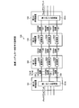
- FIG. 9 is an explanatory diagram illustrating an example of the communication system 100.
- a communication system 100 illustrated in FIG. 9 includes a first termination device 101, a first relay device 102, a second relay device 103, and a second termination device 104.
- the first terminal device 101 is connected to, for example, three 100 GBE (Giga Bit Ethernet) lines 105 with the first relay device 102.
- the first relay apparatus 102 is connected to, for example, three 100 GBE lines 105 and is connected to the second relay apparatus 103 with three ODU (Optical Data Unit) 4 lines 106.
- N Optical Transport Network
- the second relay apparatus 103 is an OTN apparatus that is connected to, for example, three ODU4 lines 106 and is connected to the three 100 GBE lines 107 with the second termination apparatus 104.
- the first terminal device 101 includes a first shim processing unit 101A that executes FlexE signal processing between a plurality of FlexE clients and three 100 GBE lines 105.
- the first relay apparatus 102 includes, for example, a conversion unit 102A that maps a 100 GBE signal from the 100 GBE line 105 to an ODU4 signal and demaps an ODU4 signal from the ODU4 line 106 to a 100 GBE signal.
- the second relay apparatus 103 includes, for example, a conversion unit 103A that demaps an ODU4 signal from the ODU4 line 106 into a 100GBE signal and maps a 100GBE signal from the 100GBE line 107 into an ODU4 signal.
- the second terminal device 104 includes a second shim processing unit 104A that executes FlexE signal processing between a plurality of FlexE clients and three 100 GBE lines 107.
- the first terminator 101 is connected to the three 100 GBE lines 105 and the second terminator 104 is similarly connected to the three 100 GBE lines 107, and the first terminator 101 and the second terminator 104 are not connected to each other. It is connected to three 100 GBE lines and the circuit configuration is the same.
- the first terminal device 101 outputs three 100 GBE signals to the first relay device 102. Further, the first relay apparatus 102 converts the three 100 GBE signals into three ODU4 signals and outputs the three ODU4 signals to the second relay apparatus 103. Further, the second relay apparatus 102 converts the three ODU4 signals into three 100 GBE signals and outputs the three 100 GBE signals to the second termination apparatus 104.
- the first terminal device 101 can transmit a large-capacity FlexE signal to and from the second terminal device 104 via the first relay device 102 and the second relay device 103.
- the first termination device 101 side when the first termination device 101 side is connected to three 100 GBE lines and the second termination device 104 side is connected to one 400 GBE line, the first termination device 101 and the second termination device 104 are connected.
- the line configuration is different. Therefore, since the second relay apparatus 104 does not have a function of converting signals between three 100 GBE signals and one 400 GBE signal, between the first termination apparatus 101 and the second termination apparatus 104.
- Cannot relay FlexE signal That is, since the first termination device 101 and the second termination device 104 cannot recognize the communication capacity on the opposite side, the FlexE signal between the first termination device 101 and the second termination device 104 is relayed. Can not.
- a communication device capable of ensuring signal relay between the first termination device and the second termination device even when the line configuration is different between the first termination device and the second termination device.
- the purpose is to provide.
- One communication device includes a reception unit, a descrambling unit, a detection unit, a generation unit, a scramble processing unit, and an output unit.
- the receiving unit receives a signal from the first line.
- the descrambling unit performs descrambling processing on the received signal.
- the detection unit detects a control signal from the descrambled signal.
- the generation unit generates a signal in which an idle signal corresponding to a difference amount between the communication capacity of the second transmission destination line and the communication capacity of the first line is inserted at a position where the control signal is detected.
- the scramble processing unit performs scramble processing on the generated signal.
- the output unit outputs the scrambled signal to the second line.
- FIG. 1 is an explanatory diagram illustrating an example of a communication system according to the first embodiment.
- FIG. 2 is an explanatory diagram illustrating an example of a functional configuration of the relay apparatus.
- FIG. 3 is an explanatory diagram illustrating an example of a table configuration of the bandwidth table.
- FIG. 4 is an explanatory diagram illustrating an example of a signal multiplexing configuration of the relay apparatus.
- FIG. 5 is an explanatory diagram illustrating an example of a functional configuration of the relay apparatus according to the second embodiment.
- FIG. 6 is an explanatory diagram illustrating an example of a signal multiplexing configuration of the relay apparatus according to the second embodiment.
- FIG. 7 is an explanatory diagram illustrating an example of a functional configuration of the relay device according to the third embodiment.
- FIG. 8 is an explanatory diagram of an example of a communication system according to the fourth embodiment.
- FIG. 9 is an explanatory diagram illustrating an example of a communication system.
- FIG. 1 is an explanatory diagram illustrating an example of a communication system 1 according to the first embodiment.
- a communication system 1 illustrated in FIG. 1 includes a first termination device 2, an OTN (Optical Transport Network) device 3, a relay device 4, and a second termination device 5.
- the first terminal device 2 is connected to the OTN device 3 through three 100 GBE lines 6 of FlexE (Flex Ethernet).
- the OTN device 3 is connected to the relay device 4 by three ODU4 lines 7.
- the relay device 4 is connected to the second terminal device 5 by one FlexE 400 GBE line 8. Since the first terminal device 2 is connected to three 100 GBE lines 6 and the second terminal device 5 is connected to one 400 GBE line 8,
- the FlexE line configuration differs between the first termination device 2 and the second termination device 5.
- the FlexE line is, for example, an unaware system in which clients are transmitted as one FlexE group.
- the first termination device 2 includes a first shim processing unit 2A.
- the first shim processing unit 2 ⁇ / b> A is a signal processing unit that manages signal processing between a plurality of FlexE clients and three 100 GBE lines 6.
- the OTN device 3 has a conversion unit 3A for each 100 GBE line 6.
- the conversion unit 3A maps a 100 GBE signal from the 100 GBE line 6 to an ODU4 signal, and demaps an ODU4 signal from the ODU4 line 7 to a 100 GBE signal.
- the second termination device 5 includes a second processing unit 5A.
- the relay device 4 converts, for example, a 300 GBE signal obtained from three ODU4 signals from the ODU4 line 7 into one 400 GBE signal.
- the relay device 4 converts one 400 GBE signal from the 400 GBE line 8 into three ODU4 signals corresponding to the 300 GBE signal.
- the second shim processing unit shown in FIG. 9 has the function of the shim processing unit 4X in the relay device 4.
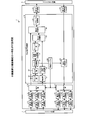
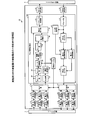
- FIG. 2 is an explanatory diagram illustrating an example of a functional configuration of the relay device 4.
- the relay apparatus 4 shown in FIG. 2 includes a first receiving unit 11, a first converting unit 12, a MUX unit 13, a FlexE signal processing unit 14, a first transmitting unit 15, and a second receiving unit. 16, a DEMUX unit 17, a second conversion unit 18, and a second transmission unit 19.
- the shim processing unit 4X includes, for example, a MUX unit 13, a DEMUX unit 17, and an extraction unit 21.
- the first receiving unit 11 receives the ODU4 signal from the ODU4 line 7.
- the first conversion unit 12 demaps the ODU4 signal into a 100 GBE signal.
- the MUX unit 13 multiplexes three 100 GBE signals from each first conversion unit 12 and outputs a 300 GBE signal.
- the FlexE signal processing unit 14 converts the 300 GBE signal from the MUX unit 13 into a 400 GBE signal.
- the first transmitter 15 outputs the 400 GBE signal from the FlexE signal processor 14 to the 400 GBE line 8 on the second terminal device 5 side.
- the second receiving unit 16 receives one 400 GBE signal from the 400 GBE line 8.
- the FlexE signal processing unit 14 converts a 400 GBE signal, which will be described later, into a 300 GBE signal.
- the DEMUX unit 17 separates and outputs the 300 GBE signal into three 100 GBE signals.
- the DEMUX unit 17 outputs three 100 GBE signals to each second conversion unit 18.
- Each second conversion unit 18 maps the 100 GBE signal to the ODU4 signal.
- Each second transmission unit 19 outputs the ODU4 signal mapped by the second conversion unit 18 to the ODU4 line 7.
- the FlexE signal processing unit 14 includes an extraction unit 21, an idle signal generation unit 22, a decoding unit 23, a monitor unit 24, a table control unit 25, and a bandwidth table 26.
- the FlexE signal processing unit 14 includes a control signal generation unit 27, an encoding unit 28, a first multiplexing unit 29, a second multiplexing unit 30, a scramble processing unit 31, and a band control unit 32.
- the extraction unit 21 collects the communication capacity for each physical port number from the FlexE shim information of the 300 GBE signal from the MUX unit 13.
- the FlexE shim information is stored in the FlexE signal.
- the physical port number is, for example, a port number that identifies a physical port connected to each 100 GBE line 6.
- the communication capacity is a communication allowable band amount of the FlexE signal passing through the physical port.
- the idle signal generator 22 calculates a difference amount between the communication capacity (300 GBE) on the first terminal device 2 side and the communication capacity (400 GBE) on the second terminal device 5 side. Further, the idle signal generation unit 22 generates an idle signal corresponding to 100 GBE, which is a difference amount.
- the idle signal is a blank 66B FlexE signal after 64B / 66B encoding.
- the idle signal is multiplexed by a multiplexing unit 30 described later.
- the decoding unit 23 decodes the 66B 100 GBE signal after 64B / 66B encoding from the MUX unit 13 into a 64B 100 GBE signal.
- the monitor unit 24 identifies a VLAN (Virtual Local Area Network) identifier from the MAC frame in the 64B 100 GBE signal.
- the VLAN identifier is an identifier for identifying the FlexE client of the first terminal device 2, for example.
- the monitor unit 24 counts signals for each VLAN identifier. The count may always be counted, but may be the result of extracting one calendar slot at random, and can be changed as appropriate. If there is one FlexE client, VLAN identification can be made unnecessary.
- the table control unit 25 registers the communication capacity in units of VLAN identifiers of the FlexE signal in the bandwidth table 26 for each physical port number.
- FIG. 3 is an explanatory diagram illustrating an example of a table configuration of the bandwidth table 26.
- the bandwidth table 26 illustrated in FIG. 3 manages the port number 26A, the communication capacity 26B, and the VLAN identifier 26C in association with each other.
- the port number 26A is a number for identifying a physical port that passes the FlexE signal.
- the communication capacity 26B is a communication capacity for each VLAN identifier in the physical port.
- the VLAN identifier 26C is an identifier for identifying a VLAN.
- the FlexE signal processing unit 14 can recognize the communication capacity for each VLAN identifier for each physical port connected to the FlexE line with reference to the bandwidth table 26.
- the control signal generator 27 generates a control signal, for example, OAM (Operations, Administration, Maintenance) based on the contents of the band table 26.
- the control signal is, for example, an ITU-T G.O. 8013 / Y. 1731 BW notification function and Pause function.
- the control signal is, for example, information for notifying the second terminal device 5 of the communication capacity on the first terminal device 2 side that is the transmission source.
- the control signal is a 64B control signal.
- the encoding unit 28 encodes the 64B control signal into a 66B control signal.
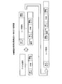
- FIG. 4 is an explanatory diagram illustrating an example of a signal multiplexing configuration of the relay device 4.
- the first multiplexing unit 29 receives the encoded 66B control signal from the encoding unit 28 and the 66B blank idle signal corresponding to 100 GBE from the idle signal generation unit 22.
- the control signal 66B shown in FIG. 4 includes an OAM, a start code at the beginning of the OAM, and an end code at the end of the OAM.
- the first multiplexing unit 29 replaces part of an idle signal equivalent to 100 GBE with a control signal of the same size.
- the second multiplexing unit 30 receives the 66 GB user signal of the 300 GBE signal from the MUX unit 13 and the 66 B idle signal after storing the control signal from the first multiplexing unit 29.
- the user signal 66B shown in FIG. 4 includes a user signal, a start code at the beginning of the user signal, and an end code at the end of the user signal. Then, the second multiplexing unit 30 inserts the 66B idle signal and the control signal generated by the first multiplexing unit 29 between the 66B user signal and the user signal. As a result, the second multiplexing unit 30 adds the 66B 300 GBE user signal and the 66B 100 GBE equivalent idle signal, and outputs the 66B 400 GBE signal to the scramble processing unit 31. In this function, a mechanism for buffering in one user signal (frame) unit is included so that an idle can be surely inserted between user signals (so that data is not lost in the middle of a frame).
- the scramble processing unit 31 performs scramble processing on the 400 GBE signal from the second multiplexing unit 30 and outputs the scrambled 400 GBE signal to the first transmission unit 15.
- the first transmission unit 15 outputs one 400 GBE signal to the 400 GBE line 8.
- the second processing unit 5 ⁇ / b> A in the second terminal device 5 extracts a control signal from an idle signal equivalent to 100 GBE in the 400 GBE signal. Based on the control signal, the second processing unit 5A recognizes that the communication capacity of the first terminal device 2 that is the transmission source is three 100 GBE lines, that is, a communication capacity of 300 GBE. As a result, when transmitting the FlexE signal to the first termination device 2, the second termination device 5 adds an idle signal equivalent to 100GBE to the 300GBE signal to generate a 400GBE signal. The 0GBE signal is output to the 400GBE line 8.
- the second receiving unit 16 in the relay apparatus 4 receives a 400 GBE signal from one 400 GBE line 8.
- the band control unit 32 deletes an idle signal equivalent to 100 GBE from the 400 GBE signal based on the communication capacity (300 GBE) of the transmission source first terminal device 2.
- the band control unit 32 outputs the deleted 300 GBE signal to the DEMUX unit 17.
- the DEMUX unit 17 Based on the FlexE shim information, the DEMUX unit 17 separates and outputs the 300 GBE signal to three 100 GBE signals.
- the DEMUX unit 17 outputs each 100 GBE signal to the second conversion unit 18.
- Each second converter 18 maps the 100 GBE signal from the DEMUX unit 17 to the ODU4 signal.
- Each second transmission unit 19 outputs an ODU4 signal to the ODU4 line.
- the relay device 4 outputs three ODU4 signals to the OTN device 3.
- the OTN device 3 receives three ODU4 signals, converts the three ODU4 signals into three 100 GBE signals, and outputs the three 100 GBE signals to the first termination device 2.
- the first terminal device 2 receives the three 100 GBE signals and outputs the three 100 GBE signals to the FlexE client.
- the relay device 4 When the relay device 4 according to the first embodiment receives a 300 GBE signal from three ODU4 lines 7 corresponding to three 100 GBE lines, it extracts the communication capacity (300 GBE) of the transmission source from the FlexE shim information in the 300 GBE signal. To do.
- the relay device 4 generates an idle signal equivalent to 100 GBE according to the difference between the communication capacity of the 400 GBE line 8 and the communication capacity of the three ODU4 lines 7 (300 GBE). Further, the relay device 4 generates one 400 GBE signal obtained by adding an idle signal equivalent to 100 GBE to a user signal equivalent to 300 GBE in the 300 GBE signal. Further, the relay device 4 outputs one 400 GBE signal to the 400 GBE line 8.
- the relay device 4 is configured to have a FlexE between the first termination device 2 and the second termination device 5 even when the line configuration is different between the three 100 GBE lines 6 and the one 400 GBE line 8. Signal relay can be realized.
- the relay device 4 inserts the communication capacity of three 100 GBE lines into the idle signal equivalent to 100 GBE, adds the idle signal equivalent to 100 GBE to the user signal, and notifies the second terminating device 4 of the 400 GBE signal. As a result, the relay device 4 can notify the second terminal device 5 of the communication capacity (300 GBE) on the first terminal device 2 side, which is the communication capacity of the transmission source.
- the relay device 4 When the relay device 4 receives a 400 GBE signal from the 400 GBE line 8, the relay device 4 deletes an idle signal equivalent to 100 GBE from the 400 GBE signal based on the communication capacity of the three 100 GBE lines on the first terminal device 2 side, and the 300 GBE signal Is output to the DEMUX unit 17. As a result, the relay device 4 can relay and output the 400 GBE signal from the 400 GBE line 8 to the three 100 GBE lines 6.
- the relay device 4 extracts the communication capacity for each VLAN identifier from the 300 GBE signal. As a result, the relay device 4 can output a FlexE signal corresponding to the VLAN configuration to the 400 GBE line 8 based on the communication capacity for each VLAN identifier. Further, the relay device 4 inserts the communication capacity for each VLAN identifier into the idle signal as the communication capacity of the 100 GBE line 6 ⁇ 3. As a result, the relay device 4 can notify the second termination device 5 of the communication capacity for each VLAN identifier of the three 100 GBE lines 6.
- the relay device 4 outputs the 66B 300 GBE signal to the second multiplexing unit 30 without decoding the 66B 300 GBE signal, which is the main signal from the MUX unit 13, into 64B. As a result, the relay device 4 does not need to perform 66B encoding again after 64B decoding of the main signal, and thus can cope with the extension of IEEE 802.3 Sequence ordered set.
- an idle signal corresponding to the difference amount is added based on the start code and end code of the user signal, but IFG (Inter Frame Gap) is performed based on the control bit in the bit string of the user signal.
- IFG Inter Frame Gap
- An idle signal may be inserted after determination, and the embodiment will be described below as a second embodiment.
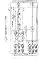
- FIG. 5 is an explanatory diagram illustrating an example of a functional configuration of the relay device 4A according to the second embodiment. Note that the same components as those of the relay device 4 shown in FIG. 3 are denoted by the same reference numerals, and the description of the overlapping configuration and operation is omitted.
- the FlexE signal processing unit 14A illustrated in FIG. 5 includes an extraction unit 21, an idle signal generation unit 22, a decoding unit 23, a monitor unit 24, a table control unit 25, a band table 26, and a control signal generation unit 27. And an encoding unit 28 and a band control unit 32.
- the FlexE signal processing unit 14A includes a first scramble processing unit 33, a second scramble processing unit 34, a detection unit 35, and a third multiplexing unit 36.
- the second scramble processing unit 34 executes scramble processing on the 66B control signal from the encoding unit 28 and inputs the scrambled control signal to the third multiplexing unit 36.
- the idle signal generation unit 22 inputs a 100 GBE idle signal corresponding to the difference amount to the third multiplexing unit 36.
- the detection unit 35 detects IFG from the 300 GBE signal. Since the detection unit 35 is a scrambled 66B 300 GBE signal, the start code and the end code of the frame cannot be identified because only the first “01” or “10” in the 66B column can be identified. Therefore, it is detected that the control signal continues for a certain interval or more, and is determined to be an IFG between MAC frames.
- the third multiplexing unit 36 stores the control signal in the idle signal.
- the control signal shown in FIG. 6 has an OAM, a start code at the beginning of the OAM, and an end code at the end of the OAM. Further, the third multiplexing unit 36 inserts the idle signal equivalent to 100 GBE after storing the control signal into the IFG of the 300 GBE signal, that is, the position where the idle signal existing in the 300 GBE signal exists.
- the third multiplexing unit 36 can insert an idle signal and a control signal equivalent to 100 GBE into the 300 GBE signal, so that it can be output to the 400 GBE line 8 as a 400 GBE signal. Even for such a signal, the receiving side, that is, the second terminating device 5 shown in FIG. 1 can restore the user signal and the control signal by dropping the continuous idle.
- the relay apparatus 4A detects an IFG in the 300 GBE signal, and generates a 400 GBE signal by inserting an idle signal into which the communication capacity of the three 100 GBE lines 6 is inserted at the position of the IFG. As a result, the relay device 4A can easily insert an idle signal.
- the relay device 4A does not descramble the scrambled 300GBE signal, and detects the IFG from only the control bit additional signal of the 66B signal from the bit string of the 300GBE signal. As a result, the relay device 4A can easily detect the IFG from the bit string.
- the communication capacities of the transmission source 100 GBE line 6 and the transmission destination 400 GBE line 8 are directly detected from the signal.
- the transmission line communication capacity and the transmission destination line communication capacity are detected. May be stored in advance.
- the idle signal equivalent to 100 GBE is deleted from the 400 GBE signal.
- the same components as those of the relay device 4 according to the first embodiment are denoted by the same reference numerals, and the description of the overlapping configuration and operation is omitted.
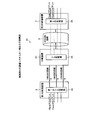
- FIG. 7 is an explanatory diagram illustrating an example of a functional configuration of the relay device 4B according to the third embodiment.
- the FlexE signal processing unit 14B illustrated in FIG. 7 includes an extraction unit 21, an idle signal generation unit 22, a decoding unit 23, a monitor unit 24, a table control unit 25, a band table 26, a control signal generation unit 27, and an encoding unit 28.
- the FlexE signal processing unit 14B includes a first multiplexing unit 29, a second multiplexing unit 30, and a scramble processing unit 31.
- the FlexE signal processing unit 14B includes a decoding unit 41, a VLAN identification unit 42, a first selector 43, a first band control unit 44, a second band control unit 45, and a second selector 46. And have.
- the decoding unit 41 decodes the 66B 400 GBE signal from the second receiving unit 16 into a 64B 400 GBE signal.
- the VLAN identifying unit 42 identifies the VLAN identifier from the MAC frame of the 64B 400 GBE signal.
- the first selector 43 inputs a 64B FlexE signal (400 GBE signal) to the first band control unit 44 or the second band control unit 45 in accordance with the selector signal.
- the selector signal is a signal for selecting the input of the first band control unit 44 or the second band control unit 45 in accordance with the setting.
- the first band control unit 44 removes an idle signal equivalent to 100 GBE from the 400 GBE signal.
- the first band control unit 44 inputs the 300 GBE signal after removal of the idle signal to the second selector 46.
- the second bandwidth control unit 45 extracts the FlexE signal for each VLAN identifier from the 400 GBE signal based on the identification result of the VLAN identification unit 42.
- the second bandwidth control unit 45 inputs the FlexE signal for each VLAN identifier to the second selector 46.
- the FlexE signal for each VLAN identifier is a 300 GBE signal.
- the second selector 46 outputs the 300 GBE signal from the first band control unit 44 or the second band control unit 45 to the DEMUX unit 17 according to the selector signal.
- the selector signal is a signal for selecting the output of the first band control unit 44 or the second band control unit 45 in accordance with the setting.
- the first band control unit 44 deletes the idle signal equivalent to 100 GBE from the 400 GBE signal, and the deleted 300 GBE A signal can be output to the DEMUX unit 17.
- the second bandwidth control unit 45 extracts the communication capacity for each VLAN identifier from the 400 GBE signal, and the idle signal of 100 GBE 300 GB signals can be output to the DEMUX unit 17.
- the communication system 1 shown in FIG. 1 exemplifies the case where the first termination device 2, the OTN device 3, the relay device 4, and the second termination device 5 are included. However, the communication system 1 does not pass through the OTN device 3. Since it may be changed as appropriate, the embodiment will be described as Example 4.
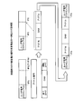
- FIG. 8 is an explanatory diagram of an example of the communication system 1A according to the fourth embodiment.
- the same components as those of the communication system 1 according to the first embodiment are denoted by the same reference numerals, and the description of the configuration and operation is omitted.
- a communication system 1A illustrated in FIG. 8 includes a first termination device 2, a relay device 4C, and a second termination device.
- the first terminal device 2 and the relay device 4C are connected by three 100 GBE lines 6.
- the relay device 4C and the second terminal device 5 are connected by a single 400 GBE line 8.
- the relay device 4C does not have the first conversion unit 12 and the second conversion unit 18, and directly connects the first reception unit 11 and the MUX unit 13.
- the MUX unit 13 inputs the three 100 GBE signals received by the first receiving units 11 to the MUX unit 13.
- the relay device 4 ⁇ / b> C directly connects the DEMUX unit 17 and the second receiving unit 16.
- the DMUX unit 17 separates the 300 GBE signal from the band control unit 32 into a 100 GBE signal and outputs it to each second transmission unit 19.
- the relay device 4C When the relay device 4C receives 300 GBE signals from the three 100 GBE lines 6, the relay device 4 C extracts the transmission capacity (300 GBE) from the FlexE shim information in the 300 GBE signals.
- the relay device 4 generates an idle signal equivalent to 100 GBE according to the difference between the communication capacity of the 400 GBE line 8 and the communication capacity of the three 100 GBE lines 6. Further, the relay device 4 generates one 400 GBE signal obtained by adding an idle signal equivalent to 100 GBE to a user signal equivalent to 300 GBE in the 300 GBE signal. Further, the relay device 4 outputs one 400 GBE signal to the 400 GBE line 8.
- the relay device 4 relays the FlexE signal between the three 100 GBE lines 6 and the 400 GBE lines 8 even when the line configuration is different between the three 100 GBE lines 6 and the one 400 GBE line 8. Can be realized.
- each component of each part illustrated does not necessarily need to be physically configured as illustrated.
- the specific form of distribution / integration of each part is not limited to the one shown in the figure, and all or a part thereof may be functionally or physically distributed / integrated in arbitrary units according to various loads and usage conditions. Can be configured.
- processing functions performed in each device are performed on a CPU (Central Processing Unit) (or a microcomputer such as an MPU (Micro Processing Unit), MCU (Micro Controller Unit), etc.) in whole or in part. You may make it perform.
- Various processing functions may be executed entirely or arbitrarily on a program that is analyzed and executed by a CPU (or a microcomputer such as an MPU or MCU) or hardware based on wired logic. Needless to say.
Abstract
[Problem] To provide a communication device and the like with which the relaying of signals between a first terminal device and a second terminal device can be ensured even when the line configuration differs between the first terminal device and the second terminal device. [Solution] A communication device having a reception unit, a descrambling unit, a detection unit, a generation unit, a scramble processing unit, and an output unit. The reception unit receives a signal from a first line. The descrambling unit performs a descrambling process on the received signal. The detection unit detects a control signal from the descrambled signal. The generation unit generates a signal wherein an idle signal in accordance with the difference in capacity between the communication capacity of a second line that is a transmission source and the communication capacity of the first line is inserted at the position where the control signal was detected. The scramble processing unit performs a scrambling process on the generated signal. The output unit outputs the scrambled signal to the second line.
Description
本発明は、通信装置及び信号中継方法に関する。
The present invention relates to a communication device and a signal relay method.
近年、データセンタの普及により、大容量、かつ、長距離伝送を可能にする伝送技術として、トラフィックを10G、25G又は40G単位で多重化し、100Gのデータ伝送を可能にするFlexE(Flex Ethernet)技術がある。FlexE技術、http://www.oiforum.com/wp-content/uploads/OIF-FLEXE-01.0.pdfで公開されている。
In recent years, with the widespread use of data centers, FlexE (Flex Ethernet) technology that enables the transmission of 100G data by multiplexing traffic in units of 10G, 25G, or 40G as a transmission technology that enables large-capacity and long-distance transmission There is. FlexE technology, http://www.oiforum.com/wp-content/uploads/OIF-FLEXE-01.0.pdf.
図9は、通信システム100の一例を示す説明図である。図9に示す通信システム100は、第1の終端装置101と、第1の中継装置102と、第2の中継装置103と、第2の終端装置104とを有する。第1の終端装置101は、例えば、第1の中継装置102との間で3本の100GBE(Giga Bit Ethernet)回線105と接続する。第1の
中継装置102は、例えば、3本の100GBE回線105と接続すると共に、第2の中継装置103との間で3本のODU(Optical Data Unit)4回線106と接続するOT
N(Optical Transport Network)装置である。更に、第2の中継装置103は、例えば
、3本のODU4回線106と接続すると共に、第2の終端装置104との間で3本の100GBE回線107と接続するOTN装置である。 FIG. 9 is an explanatory diagram illustrating an example of thecommunication system 100. A communication system 100 illustrated in FIG. 9 includes a first termination device 101, a first relay device 102, a second relay device 103, and a second termination device 104. The first terminal device 101 is connected to, for example, three 100 GBE (Giga Bit Ethernet) lines 105 with the first relay device 102. The first relay apparatus 102 is connected to, for example, three 100 GBE lines 105 and is connected to the second relay apparatus 103 with three ODU (Optical Data Unit) 4 lines 106.
N (Optical Transport Network) device. Further, thesecond relay apparatus 103 is an OTN apparatus that is connected to, for example, three ODU4 lines 106 and is connected to the three 100 GBE lines 107 with the second termination apparatus 104.
中継装置102は、例えば、3本の100GBE回線105と接続すると共に、第2の中継装置103との間で3本のODU(Optical Data Unit)4回線106と接続するOT
N(Optical Transport Network)装置である。更に、第2の中継装置103は、例えば
、3本のODU4回線106と接続すると共に、第2の終端装置104との間で3本の100GBE回線107と接続するOTN装置である。 FIG. 9 is an explanatory diagram illustrating an example of the
N (Optical Transport Network) device. Further, the
第1の終端装置101は、複数のFlexEクライアントと3本の100GBE回線105との間のFlexE信号処理を実行する第1のシム処理部101Aを有する。第1の中継装置102は、例えば、100GBE回線105からの100GBE信号をODU4信号にマッピングすると共に、ODU4回線106からのODU4信号を100GBE信号にデマッピングする変換部102Aを有する。更に、第2の中継装置103は、例えば、ODU4回線106からのODU4信号を100GBE信号にデマッピングすると共に、100GBE回線107からの100GBE信号をODU4信号にマッピングする変換部103Aを有する。第2の終端装置104は、複数のFlexEクライアントと3本の100GBE回線107との間のFlexE信号処理を実行する第2のシム処理部104Aを有する。
The first terminal device 101 includes a first shim processing unit 101A that executes FlexE signal processing between a plurality of FlexE clients and three 100 GBE lines 105. The first relay apparatus 102 includes, for example, a conversion unit 102A that maps a 100 GBE signal from the 100 GBE line 105 to an ODU4 signal and demaps an ODU4 signal from the ODU4 line 106 to a 100 GBE signal. Furthermore, the second relay apparatus 103 includes, for example, a conversion unit 103A that demaps an ODU4 signal from the ODU4 line 106 into a 100GBE signal and maps a 100GBE signal from the 100GBE line 107 into an ODU4 signal. The second terminal device 104 includes a second shim processing unit 104A that executes FlexE signal processing between a plurality of FlexE clients and three 100 GBE lines 107.
第1の終端装置101は3本の100GBE回線105、第2の終端装置104も同様に3本の100GBE回線107と接続し、第1の終端装置101と第2の終端装置104との間は3本の100GBE回線と接続し、その回路構成が同じである。第1の終端装置101は、第1の中継装置102に対して3本の100GBE信号を出力する。更に、第1の中継装置102は、3本の100GBE信号を3本のODU4信号に変換し、3本のODU4信号を第2の中継装置103に出力する。更に、第2の中継装置102は、3本のODU4信号を3本の100GBE信号に変換し、3本の100GBE信号を第2の終端装置104に出力する。その結果、第1の終端装置101は、第1の中継装置102及び第2の中継装置103を経由して第2の終端装置104との間で大容量のFlexE信号を伝送できる。
The first terminator 101 is connected to the three 100 GBE lines 105 and the second terminator 104 is similarly connected to the three 100 GBE lines 107, and the first terminator 101 and the second terminator 104 are not connected to each other. It is connected to three 100 GBE lines and the circuit configuration is the same. The first terminal device 101 outputs three 100 GBE signals to the first relay device 102. Further, the first relay apparatus 102 converts the three 100 GBE signals into three ODU4 signals and outputs the three ODU4 signals to the second relay apparatus 103. Further, the second relay apparatus 102 converts the three ODU4 signals into three 100 GBE signals and outputs the three 100 GBE signals to the second termination apparatus 104. As a result, the first terminal device 101 can transmit a large-capacity FlexE signal to and from the second terminal device 104 via the first relay device 102 and the second relay device 103.
しかしながら、例えば、図9において第1の終端装置101側が3本の100GBE回線、第2の終端装置104側が1本の400GBE回線と接続する場合、第1の終端装置101と第2の終端装置104との間の回線構成が異なる。従って、第2の中継装置104は、3本の100GBE信号と1本の400GBE信号との間で信号変換する機能がないため、第1の終端装置101と第2の終端装置104との間でFlexE信号を中継できない。つまり、第1の終端装置101及び第2の終端装置104は、相互に対向側の通信容量を認識できないため、第1の終端装置101と第2の終端装置104との間のFlexE信号を中継できない。
However, for example, in FIG. 9, when the first termination device 101 side is connected to three 100 GBE lines and the second termination device 104 side is connected to one 400 GBE line, the first termination device 101 and the second termination device 104 are connected. The line configuration is different. Therefore, since the second relay apparatus 104 does not have a function of converting signals between three 100 GBE signals and one 400 GBE signal, between the first termination apparatus 101 and the second termination apparatus 104. Cannot relay FlexE signal. That is, since the first termination device 101 and the second termination device 104 cannot recognize the communication capacity on the opposite side, the FlexE signal between the first termination device 101 and the second termination device 104 is relayed. Can not.
一つの側面では、第1の終端装置と第2の終端装置との間で回線構成が異なる場合でも、第1の終端装置と第2の終端装置との間の信号の中継を確保できる通信装置等を提供することを目的とする。
In one aspect, a communication device capable of ensuring signal relay between the first termination device and the second termination device even when the line configuration is different between the first termination device and the second termination device. The purpose is to provide.
一つの案の通信装置は、通信装置は、受信部と、デスクランブル部と、検出部と、生成部と、スクランブル処理部と、出力部とを有する。受信部は、第1の回線から信号を受信する。デスクランブル部は、受信した信号にデスクランブル処理を行う。検出部は、デスクランブルされた信号から制御信号を検出する。生成部は、送信先の第2の回線の通信容量と第1の回線の通信容量との差分量に応じたアイドル信号を制御信号が検出された位置に挿入した信号を生成する。スクランブル処理部は、生成した信号にスクランブル処理を行う。出力部は、スクランブル処理した信号を第2の回線に出力する。
One communication device includes a reception unit, a descrambling unit, a detection unit, a generation unit, a scramble processing unit, and an output unit. The receiving unit receives a signal from the first line. The descrambling unit performs descrambling processing on the received signal. The detection unit detects a control signal from the descrambled signal. The generation unit generates a signal in which an idle signal corresponding to a difference amount between the communication capacity of the second transmission destination line and the communication capacity of the first line is inserted at a position where the control signal is detected. The scramble processing unit performs scramble processing on the generated signal. The output unit outputs the scrambled signal to the second line.
第1の終端装置と第2の終端装置との間で回線構成が異なる場合でも、第1の終端装置と第2の終端装置との間の信号の中継を確保できる。
Even when the line configuration differs between the first termination device and the second termination device, signal relay between the first termination device and the second termination device can be ensured.
以下、図面に基づいて、本願の開示する通信装置及び信号中継方法の実施例を詳細に説明する。尚、本実施例により、開示技術が限定されるものではない。また、以下に示す実施例は、矛盾を起こさない範囲で適宜組み合わせても良い。
Hereinafter, embodiments of a communication device and a signal relay method disclosed in the present application will be described in detail based on the drawings. The disclosed technology is not limited by the present embodiment. Moreover, you may combine suitably the Example shown below in the range which does not cause contradiction.
図1は、実施例1の通信システム1の一例を示す説明図である。図1に示す通信システム1は、第1の終端装置2と、OTN(Optical Transport Network)装置3と、中継装
置4と、第2の終端装置5とを有する。第1の終端装置2は、OTN装置3との間をFlexE(Flex Ethernet)の3本の100GBE回線6で接続する。OTN装置3は、中継装置4との間を3本のODU4回線7で接続する。中継装置4は、第2の終端装置5との間をFlexEの1本の400GBE回線8で接続する。尚、第1の終端装置2は3本の100GBE回線6、第2の終端装置5は1本の400GBE回線8と接続するため、
第1の終端装置2と第2の終端装置5との間でFlexEの回線構成が異なる。尚、FlexE回線は、例えば、クライアントを1FlexEグループとして伝送するunaware方式とする。 FIG. 1 is an explanatory diagram illustrating an example of acommunication system 1 according to the first embodiment. A communication system 1 illustrated in FIG. 1 includes a first termination device 2, an OTN (Optical Transport Network) device 3, a relay device 4, and a second termination device 5. The first terminal device 2 is connected to the OTN device 3 through three 100 GBE lines 6 of FlexE (Flex Ethernet). The OTN device 3 is connected to the relay device 4 by three ODU4 lines 7. The relay device 4 is connected to the second terminal device 5 by one FlexE 400 GBE line 8. Since the first terminal device 2 is connected to three 100 GBE lines 6 and the second terminal device 5 is connected to one 400 GBE line 8,
The FlexE line configuration differs between thefirst termination device 2 and the second termination device 5. Note that the FlexE line is, for example, an unaware system in which clients are transmitted as one FlexE group.
置4と、第2の終端装置5とを有する。第1の終端装置2は、OTN装置3との間をFlexE(Flex Ethernet)の3本の100GBE回線6で接続する。OTN装置3は、中継装置4との間を3本のODU4回線7で接続する。中継装置4は、第2の終端装置5との間をFlexEの1本の400GBE回線8で接続する。尚、第1の終端装置2は3本の100GBE回線6、第2の終端装置5は1本の400GBE回線8と接続するため、
第1の終端装置2と第2の終端装置5との間でFlexEの回線構成が異なる。尚、FlexE回線は、例えば、クライアントを1FlexEグループとして伝送するunaware方式とする。 FIG. 1 is an explanatory diagram illustrating an example of a
The FlexE line configuration differs between the
第1の終端装置2は、第1のシム処理部2Aを有する。第1のシム処理部2Aは、複数のFlexEクライアントと3本の100GBE回線6との間の信号処理を司る信号処理部である。OTN装置3は、100GBE回線6毎に変換部3Aを有する。変換部3Aは、例えば、100GBE回線6からの100GBE信号をODU4信号にマッピングする共に、ODU4回線7からのODU4信号を100GBE信号にデマッピングする。第2の終端装置5は、第2の処理部5Aを有する。中継装置4は、例えば、ODU4回線7からの3本のODU4信号から得た300GBE信号を1本の400GBE信号に変換する。更に、中継装置4は、400GBE回線8からの1本の400GBE信号を300GBE信号相当の3本のODU4信号に変換する。FlexEの構成上、図9で示す第2のシム処理部は、この中継装置4内のシム処理部4Xがその機能を担う。
The first termination device 2 includes a first shim processing unit 2A. The first shim processing unit 2 </ b> A is a signal processing unit that manages signal processing between a plurality of FlexE clients and three 100 GBE lines 6. The OTN device 3 has a conversion unit 3A for each 100 GBE line 6. For example, the conversion unit 3A maps a 100 GBE signal from the 100 GBE line 6 to an ODU4 signal, and demaps an ODU4 signal from the ODU4 line 7 to a 100 GBE signal. The second termination device 5 includes a second processing unit 5A. The relay device 4 converts, for example, a 300 GBE signal obtained from three ODU4 signals from the ODU4 line 7 into one 400 GBE signal. Further, the relay device 4 converts one 400 GBE signal from the 400 GBE line 8 into three ODU4 signals corresponding to the 300 GBE signal. In the configuration of FlexE, the second shim processing unit shown in FIG. 9 has the function of the shim processing unit 4X in the relay device 4.
図2は、中継装置4の機能構成の一例を示す説明図である。図2に示す中継装置4は、第1の受信部11と、第1の変換部12と、MUX部13と、FlexE信号処理部14と、第1の送信部15と、第2の受信部16と、DEMUX部17と、第2の変換部18と、第2の送信部19とを有する。シム処理部4Xは、例えば、MUX部13、DEMUX部17及び抽出部21を有する。
FIG. 2 is an explanatory diagram illustrating an example of a functional configuration of the relay device 4. The relay apparatus 4 shown in FIG. 2 includes a first receiving unit 11, a first converting unit 12, a MUX unit 13, a FlexE signal processing unit 14, a first transmitting unit 15, and a second receiving unit. 16, a DEMUX unit 17, a second conversion unit 18, and a second transmission unit 19. The shim processing unit 4X includes, for example, a MUX unit 13, a DEMUX unit 17, and an extraction unit 21.
第1の受信部11は、ODU4回線7からのODU4信号を受信する。第1の変換部12は、ODU4信号を100GBE信号にデマッピングする。MUX部13は、各第1の変換部12からの3本の100GBE信号を多重化して300GBE信号を出力する。FlexE信号処理部14は、MUX部13からの300GBE信号を400GBE信号に変換する。第1の送信部15は、FlexE信号処理部14からの400GBE信号を第2の終端装置5側の400GBE回線8に出力する。
The first receiving unit 11 receives the ODU4 signal from the ODU4 line 7. The first conversion unit 12 demaps the ODU4 signal into a 100 GBE signal. The MUX unit 13 multiplexes three 100 GBE signals from each first conversion unit 12 and outputs a 300 GBE signal. The FlexE signal processing unit 14 converts the 300 GBE signal from the MUX unit 13 into a 400 GBE signal. The first transmitter 15 outputs the 400 GBE signal from the FlexE signal processor 14 to the 400 GBE line 8 on the second terminal device 5 side.
第2の受信部16は、400GBE回線8からの1本の400GBE信号を受信する。FlexE信号処理部14は、後述する400GBE信号を300GBE信号に変換する。DEMUX部17は、300GBE信号を3本の100GBE信号に分離出力する。DEMUX部17は、3本の100GBE信号を各第2の変換部18に出力する。各第2の変換部18は、100GBE信号をODU4信号にマッピングする。各第2の送信部19は、第2の変換部18にてマッピングされたODU4信号をODU4回線7に出力する。
The second receiving unit 16 receives one 400 GBE signal from the 400 GBE line 8. The FlexE signal processing unit 14 converts a 400 GBE signal, which will be described later, into a 300 GBE signal. The DEMUX unit 17 separates and outputs the 300 GBE signal into three 100 GBE signals. The DEMUX unit 17 outputs three 100 GBE signals to each second conversion unit 18. Each second conversion unit 18 maps the 100 GBE signal to the ODU4 signal. Each second transmission unit 19 outputs the ODU4 signal mapped by the second conversion unit 18 to the ODU4 line 7.
FlexE信号処理部14は、抽出部21と、アイドル信号生成部22と、デコード部23と、モニタ部24と、テーブル制御部25と、帯域テーブル26とを有する。FlexE信号処理部14は、制御信号生成部27と、エンコード部28と、第1の多重部29と、第2の多重部30と、スクランブル処理部31と、帯域制御部32とを有する。
The FlexE signal processing unit 14 includes an extraction unit 21, an idle signal generation unit 22, a decoding unit 23, a monitor unit 24, a table control unit 25, and a bandwidth table 26. The FlexE signal processing unit 14 includes a control signal generation unit 27, an encoding unit 28, a first multiplexing unit 29, a second multiplexing unit 30, a scramble processing unit 31, and a band control unit 32.
抽出部21は、MUX部13からの300GBE信号のFlexEシム情報から物理ポート番号毎の通信容量を収集する。尚、FlexEシム情報は、FlexE信号内に格納している。物理ポート番号は、例えば、各100GBE回線6に接続する物理ポートを識別するポート番号である。また、通信容量は、物理ポートを通過するFlexE信号の通信許容帯域量である。アイドル信号生成部22は、第1の終端装置2側の通信容量(300GBE)と、第2の終端装置5側の通信容量(400GBE)との差分量を算出する。更に、アイドル信号生成部22は、差分量である、例えば、100GBE相当のアイドル信号を生成する。尚、アイドル信号は、64B/66B符号化後の空白の66BのFlexE信号である。このアイドル信号は、後述する多重部30にて多重される。
The extraction unit 21 collects the communication capacity for each physical port number from the FlexE shim information of the 300 GBE signal from the MUX unit 13. The FlexE shim information is stored in the FlexE signal. The physical port number is, for example, a port number that identifies a physical port connected to each 100 GBE line 6. The communication capacity is a communication allowable band amount of the FlexE signal passing through the physical port. The idle signal generator 22 calculates a difference amount between the communication capacity (300 GBE) on the first terminal device 2 side and the communication capacity (400 GBE) on the second terminal device 5 side. Further, the idle signal generation unit 22 generates an idle signal corresponding to 100 GBE, which is a difference amount. The idle signal is a blank 66B FlexE signal after 64B / 66B encoding. The idle signal is multiplexed by a multiplexing unit 30 described later.
デコード部23は、MUX部13から64B/66B符号化後の66Bの100GBE信号を64Bの100GBE信号に復号化する。モニタ部24は、64Bの100GBE信号内のMACフレームからVLAN(Virtual Local Area Network)識別子を識別
する。尚、VLAN識別子は、例えば、第1の終端装置2のFlexEクライアントを識別する識別子である。モニタ部24は、VLAN識別子毎の信号をカウントする。尚、カウントは常時カウントしても良いが、ランダムに1カレンダスロットを抽出した結果でも良く、適宜変更可能である。なお、FlexEクライアントが一つの場合、VLAN識別は不要にできる。 Thedecoding unit 23 decodes the 66B 100 GBE signal after 64B / 66B encoding from the MUX unit 13 into a 64B 100 GBE signal. The monitor unit 24 identifies a VLAN (Virtual Local Area Network) identifier from the MAC frame in the 64B 100 GBE signal. The VLAN identifier is an identifier for identifying the FlexE client of the first terminal device 2, for example. The monitor unit 24 counts signals for each VLAN identifier. The count may always be counted, but may be the result of extracting one calendar slot at random, and can be changed as appropriate. If there is one FlexE client, VLAN identification can be made unnecessary.
する。尚、VLAN識別子は、例えば、第1の終端装置2のFlexEクライアントを識別する識別子である。モニタ部24は、VLAN識別子毎の信号をカウントする。尚、カウントは常時カウントしても良いが、ランダムに1カレンダスロットを抽出した結果でも良く、適宜変更可能である。なお、FlexEクライアントが一つの場合、VLAN識別は不要にできる。 The
テーブル制御部25は、物理ポート番号毎に、FlexE信号のVLAN識別子単位の通信容量を帯域テーブル26内に登録する。図3は、帯域テーブル26のテーブル構成の一例を示す説明図である。図3に示す帯域テーブル26は、ポート番号26Aと、通信容量26Bと、VLAN識別子26Cとを対応付けて管理する。ポート番号26Aは、FlexE信号を通過する物理ポートを識別する番号である。通信容量26Bは、物理ポート内のVLAN識別子毎の通信容量である。VLAN識別子26Cは、VLANを識別する識別子である。FlexE信号処理部14は、帯域テーブル26を参照し、FlexE回線と接続する物理ポート毎のVLAN識別子毎の通信容量を認識できる。
The table control unit 25 registers the communication capacity in units of VLAN identifiers of the FlexE signal in the bandwidth table 26 for each physical port number. FIG. 3 is an explanatory diagram illustrating an example of a table configuration of the bandwidth table 26. The bandwidth table 26 illustrated in FIG. 3 manages the port number 26A, the communication capacity 26B, and the VLAN identifier 26C in association with each other. The port number 26A is a number for identifying a physical port that passes the FlexE signal. The communication capacity 26B is a communication capacity for each VLAN identifier in the physical port. The VLAN identifier 26C is an identifier for identifying a VLAN. The FlexE signal processing unit 14 can recognize the communication capacity for each VLAN identifier for each physical port connected to the FlexE line with reference to the bandwidth table 26.
制御信号生成部27は、帯域テーブル26のテーブル内容に基づき、制御信号、例えば、OAM(Operations, Administration, Maintenance)を生成する。制御信号は、例え
ば、OAMのITU-T G.8013/Y.1731のBW通知機能やPause機能である。制御信号は、例えば、送信元である第1の終端装置2側の通信容量を第2の終端装置5に通知するための情報である。尚、制御信号は、64Bの制御信号である。エンコード部28は、64Bの制御信号を66Bの制御信号に符号化する。 Thecontrol signal generator 27 generates a control signal, for example, OAM (Operations, Administration, Maintenance) based on the contents of the band table 26. The control signal is, for example, an ITU-T G.O. 8013 / Y. 1731 BW notification function and Pause function. The control signal is, for example, information for notifying the second terminal device 5 of the communication capacity on the first terminal device 2 side that is the transmission source. The control signal is a 64B control signal. The encoding unit 28 encodes the 64B control signal into a 66B control signal.
ば、OAMのITU-T G.8013/Y.1731のBW通知機能やPause機能である。制御信号は、例えば、送信元である第1の終端装置2側の通信容量を第2の終端装置5に通知するための情報である。尚、制御信号は、64Bの制御信号である。エンコード部28は、64Bの制御信号を66Bの制御信号に符号化する。 The
図4は、中継装置4の信号多重構成の一例を示す説明図である。第1の多重部29は、エンコード部28からの符号化後の66Bの制御信号を入力すると共に、アイドル信号生成部22からの100GBE相当の66Bの空白のアイドル信号を入力する。図4に示す66Bの制御信号は、OAMと、OAMの先頭に開始コードと、OAMの末尾に終了コードとを配置する。第1の多重部29は、100GBE相当のアイドル信号の一部を同じサイズの制御信号に置き換える。第2の多重部30は、MUX部13からの300GBE信号の66Bのユーザ信号を入力すると共に、第1の多重部29からの制御信号格納後の66Bのアイドル信号を入力する。図4に示す66Bのユーザ信号は、ユーザ信号と、ユーザ信号の先頭に開始コードと、ユーザ信号の末尾に終了コードとを配置する。そして、第2の多重部30は、第1の多重部29で生成した66Bのアイドル信号および制御信号を66Bのユーザ信号とユーザ信号の間に挿入する。その結果、第2の多重部30は、66Bの300GBEのユーザ信号と、66Bの100GBE相当のアイドル信号とを付加して66Bの400GBE信号をスクランブル処理部31に出力する。この機能では、確実にユーザ信号とユーザ信号の間にアイドルが挿入できるよう(フレームの途中でデータが無くなってしまわない様)、1つのユーザ信号(フレーム)単位にバッファするような仕組みが入る。スクランブル処理部31は、第2の多重部30からの400GBE信号にスクランブル処理を施し、スクランブル処理後の400GBE信号を第1の送信部15に出力する。第1の送信部15は、1本の400GBE信号を400GBE回線8に出力する。
FIG. 4 is an explanatory diagram illustrating an example of a signal multiplexing configuration of the relay device 4. The first multiplexing unit 29 receives the encoded 66B control signal from the encoding unit 28 and the 66B blank idle signal corresponding to 100 GBE from the idle signal generation unit 22. The control signal 66B shown in FIG. 4 includes an OAM, a start code at the beginning of the OAM, and an end code at the end of the OAM. The first multiplexing unit 29 replaces part of an idle signal equivalent to 100 GBE with a control signal of the same size. The second multiplexing unit 30 receives the 66 GB user signal of the 300 GBE signal from the MUX unit 13 and the 66 B idle signal after storing the control signal from the first multiplexing unit 29. The user signal 66B shown in FIG. 4 includes a user signal, a start code at the beginning of the user signal, and an end code at the end of the user signal. Then, the second multiplexing unit 30 inserts the 66B idle signal and the control signal generated by the first multiplexing unit 29 between the 66B user signal and the user signal. As a result, the second multiplexing unit 30 adds the 66B 300 GBE user signal and the 66B 100 GBE equivalent idle signal, and outputs the 66B 400 GBE signal to the scramble processing unit 31. In this function, a mechanism for buffering in one user signal (frame) unit is included so that an idle can be surely inserted between user signals (so that data is not lost in the middle of a frame). The scramble processing unit 31 performs scramble processing on the 400 GBE signal from the second multiplexing unit 30 and outputs the scrambled 400 GBE signal to the first transmission unit 15. The first transmission unit 15 outputs one 400 GBE signal to the 400 GBE line 8.
第2の終端装置5内の第2の処理部5Aは、中継装置4からの400GBE信号を受信した場合、400GBE信号内の100GBE相当のアイドル信号から制御信号を抽出する。第2の処理部5Aは、制御信号に基づき、送信元である第1の終端装置2の通信容量が3本の100GBE回線、すなわち300GBEの通信容量を認識する。その結果、第2の終端装置5は、第1の終端装置2に対してFlexE信号を伝送する場合、300GBE信号に100GBE相当のアイドル信号を付加して400GBE信号を生成し、40
0GBE信号を400GBE回線8に出力する。 When receiving the 400 GBE signal from therelay device 4, the second processing unit 5 </ b> A in the second terminal device 5 extracts a control signal from an idle signal equivalent to 100 GBE in the 400 GBE signal. Based on the control signal, the second processing unit 5A recognizes that the communication capacity of the first terminal device 2 that is the transmission source is three 100 GBE lines, that is, a communication capacity of 300 GBE. As a result, when transmitting the FlexE signal to the first termination device 2, the second termination device 5 adds an idle signal equivalent to 100GBE to the 300GBE signal to generate a 400GBE signal.
The 0GBE signal is output to the400GBE line 8.
0GBE信号を400GBE回線8に出力する。 When receiving the 400 GBE signal from the
The 0GBE signal is output to the
そして、中継装置4内の第2の受信部16は、1本の400GBE回線8からの400GBE信号を受信する。帯域制御部32は、送信元の第1の終端装置2の通信容量(300GBE)に基づき、400GBE信号から100GBE相当のアイドル信号を削除する。帯域制御部32は、削除後の300GBE信号をDEMUX部17に出力する。DEMUX部17は、FlexEシム情報に基づき、300GBE信号から3本の100GBE信号に分離出力する。DEMUX部17は、各100GBE信号を第2の変換部18に出力する。各第2の変換部18は、DEMUX部17から100GBE信号をODU4信号にマッピングする。各第2の送信部19は、ODU4信号をODU4回線に出力する。その結果、中継装置4は、3本のODU4信号をOTN装置3に出力する。OTN装置3は、3本のODU4信号を受信し、3本のODU4信号を3本の100GBE信号に変換し、3本の100GBE信号を第1の終端装置2に出力する。第1の終端装置2は、3本の100GBE信号を受信し、3本の100GBE信号をFlexEクライアントに出力する。
Then, the second receiving unit 16 in the relay apparatus 4 receives a 400 GBE signal from one 400 GBE line 8. The band control unit 32 deletes an idle signal equivalent to 100 GBE from the 400 GBE signal based on the communication capacity (300 GBE) of the transmission source first terminal device 2. The band control unit 32 outputs the deleted 300 GBE signal to the DEMUX unit 17. Based on the FlexE shim information, the DEMUX unit 17 separates and outputs the 300 GBE signal to three 100 GBE signals. The DEMUX unit 17 outputs each 100 GBE signal to the second conversion unit 18. Each second converter 18 maps the 100 GBE signal from the DEMUX unit 17 to the ODU4 signal. Each second transmission unit 19 outputs an ODU4 signal to the ODU4 line. As a result, the relay device 4 outputs three ODU4 signals to the OTN device 3. The OTN device 3 receives three ODU4 signals, converts the three ODU4 signals into three 100 GBE signals, and outputs the three 100 GBE signals to the first termination device 2. The first terminal device 2 receives the three 100 GBE signals and outputs the three 100 GBE signals to the FlexE client.
実施例1の中継装置4は、3本の100GBE回線対応の3本のODU4回線7から300GBE信号を受信した場合に、当該300GBE信号内のFlexEシム情報から送信元の通信容量(300GBE)を抽出する。中継装置4は、400GBE回線8の通信容量と3本のODU4回線7の通信容量(300GBE)との差分量に応じた100GBE相当のアイドル信号を生成する。更に、中継装置4は、300GBE信号内の300GBE相当のユーザ信号に100GBE相当のアイドル信号を付加した1本の400GBE信号を生成する。更に、中継装置4は、1本の400GBE信号を400GBE回線8に出力する。その結果、中継装置4は、3本の100GBE回線6と1本の400GBE回線8との間で回線構成が異なる場合でも、第1の終端装置2と第2の終端装置5との間のFlexE信号の中継を実現できる。
When the relay device 4 according to the first embodiment receives a 300 GBE signal from three ODU4 lines 7 corresponding to three 100 GBE lines, it extracts the communication capacity (300 GBE) of the transmission source from the FlexE shim information in the 300 GBE signal. To do. The relay device 4 generates an idle signal equivalent to 100 GBE according to the difference between the communication capacity of the 400 GBE line 8 and the communication capacity of the three ODU4 lines 7 (300 GBE). Further, the relay device 4 generates one 400 GBE signal obtained by adding an idle signal equivalent to 100 GBE to a user signal equivalent to 300 GBE in the 300 GBE signal. Further, the relay device 4 outputs one 400 GBE signal to the 400 GBE line 8. As a result, the relay device 4 is configured to have a FlexE between the first termination device 2 and the second termination device 5 even when the line configuration is different between the three 100 GBE lines 6 and the one 400 GBE line 8. Signal relay can be realized.
中継装置4は、100GBE相当のアイドル信号内に3本の100GBE回線の通信容量を挿入し、100GBE相当のアイドル信号をユーザ信号に付加して400GBE信号を第2の終端装置4に通知する。その結果、中継装置4は、送信元の通信容量である第1の終端装置2側の通信容量(300GBE)を第2の終端装置5に通知できる。
The relay device 4 inserts the communication capacity of three 100 GBE lines into the idle signal equivalent to 100 GBE, adds the idle signal equivalent to 100 GBE to the user signal, and notifies the second terminating device 4 of the 400 GBE signal. As a result, the relay device 4 can notify the second terminal device 5 of the communication capacity (300 GBE) on the first terminal device 2 side, which is the communication capacity of the transmission source.
中継装置4は、400GBE回線8から400GBE信号を受信した場合に、第1の終端装置2側の3本の100GBE回線の通信容量に基づき、400GBE信号から100GBE相当のアイドル信号を削除し、300GBE信号をDEMUX部17に出力する。その結果、中継装置4は、400GBE回線8からの400GBE信号を3本の100GBE回線6に中継出力できる。
When the relay device 4 receives a 400 GBE signal from the 400 GBE line 8, the relay device 4 deletes an idle signal equivalent to 100 GBE from the 400 GBE signal based on the communication capacity of the three 100 GBE lines on the first terminal device 2 side, and the 300 GBE signal Is output to the DEMUX unit 17. As a result, the relay device 4 can relay and output the 400 GBE signal from the 400 GBE line 8 to the three 100 GBE lines 6.
中継装置4は、300GBE信号からVLAN識別子毎の通信容量を抽出する。その結果、中継装置4は、VLAN識別子毎の通信容量に基づき、400GBE回線8に対してVLAN構成に応じたFlexE信号を出力できる。更に、中継装置4は、VLAN識別子毎の通信容量を100GBE回線6×3の通信容量としてアイドル信号に挿入する。その結果、中継装置4は、3本の100GBE回線6のVLAN識別子毎の通信容量を第2の終端装置5に通知できる。
The relay device 4 extracts the communication capacity for each VLAN identifier from the 300 GBE signal. As a result, the relay device 4 can output a FlexE signal corresponding to the VLAN configuration to the 400 GBE line 8 based on the communication capacity for each VLAN identifier. Further, the relay device 4 inserts the communication capacity for each VLAN identifier into the idle signal as the communication capacity of the 100 GBE line 6 × 3. As a result, the relay device 4 can notify the second termination device 5 of the communication capacity for each VLAN identifier of the three 100 GBE lines 6.
中継装置4は、MUX部13からの主信号である66Bの300GBE信号を64Bに復号化することなく、66Bの300GBE信号を第2の多重部30に出力する。その結果、中継装置4は、主信号を64B復号化後、再度、66B符号化する処理が不要になるため、IEEE802.3 Sequence ordered setを拡張して対応できる。
The relay device 4 outputs the 66B 300 GBE signal to the second multiplexing unit 30 without decoding the 66B 300 GBE signal, which is the main signal from the MUX unit 13, into 64B. As a result, the relay device 4 does not need to perform 66B encoding again after 64B decoding of the main signal, and thus can cope with the extension of IEEE 802.3 Sequence ordered set.
実施例1の中継装置4では、ユーザ信号の開始コード、終了コードを元に差分量相当のアイドル信号を付加したが、ユーザ信号のビット列内のコントロールビットを元に、IFG(Inter Frame Gap)を判断しアイドル信号を挿入しても良く、その実施の形態につ
き、実施例2として以下に説明する。 In therelay apparatus 4 according to the first embodiment, an idle signal corresponding to the difference amount is added based on the start code and end code of the user signal, but IFG (Inter Frame Gap) is performed based on the control bit in the bit string of the user signal. An idle signal may be inserted after determination, and the embodiment will be described below as a second embodiment.
き、実施例2として以下に説明する。 In the
図5は、実施例2の中継装置4Aの機能構成の一例を示す説明図である。尚、図3に示す中継装置4と同一の構成には同一符号を付すことで、その重複する構成及び動作の説明については省略する。
FIG. 5 is an explanatory diagram illustrating an example of a functional configuration of the relay device 4A according to the second embodiment. Note that the same components as those of the relay device 4 shown in FIG. 3 are denoted by the same reference numerals, and the description of the overlapping configuration and operation is omitted.
図5に示すFlexE信号処理部14Aは、抽出部21と、アイドル信号生成部22と、デコード部23と、モニタ部24と、テーブル制御部25と、帯域テーブル26と、制御信号生成部27と、エンコード部28と、帯域制御部32とを有する。FlexE信号処理部14Aは、第1のスクランブル処理部33と、第2のスクランブル処理部34と、検出部35と、第3の多重部36とを有する。
The FlexE signal processing unit 14A illustrated in FIG. 5 includes an extraction unit 21, an idle signal generation unit 22, a decoding unit 23, a monitor unit 24, a table control unit 25, a band table 26, and a control signal generation unit 27. And an encoding unit 28 and a band control unit 32. The FlexE signal processing unit 14A includes a first scramble processing unit 33, a second scramble processing unit 34, a detection unit 35, and a third multiplexing unit 36.
第2のスクランブル処理部34は、エンコード部28からの66Bの制御信号にスクランブル処理を実行し、スクランブル処理後の制御信号を第3の多重部36に入力する。アイドル信号生成部22は、差分量相当の100GBEのアイドル信号を第3の多重部36に入力する。検出部35は、300GBE信号からIFGを検出する。検出部35は、スクランブルされた66Bの300GBE信号であるため、66B列の内、先頭の“01”又は“10”以外は識別できないため、フレームの開始コード、終了コードが識別できない。そこで、コントロール信号が一定区間以上連続することを検出し、MACフレーム間のIFGであると判断する。図6は、実施例2の中継装置4Aの信号多重構成の一例を示す説明図である。第3の多重部36は、アイドル信号内に制御信号を格納する。尚、図6に示す制御信号は、OAMと、OAMの先頭に開始コードと、OAMの末尾に終了コードとを有する。更に、第3の多重部36は、制御信号格納後の100GBE相当のアイドル信号を300GBE信号のIFG、すなわち300GBE信号に存在するアイドル信号の存在する位置に挿入する。このことで、第3の多重部36は、100GBE相当のアイドル信号及び制御信号を300GBE信号に挿入することが可能になるので、400GBE信号として400GBE回線8に出力することができる。また、この様な信号であっても受信側、すなわち図1に示す第2の終端装置5は連続されたアイドルをドロップすることで、ユーザ信号並びに制御信号を復元することが可能になる。
The second scramble processing unit 34 executes scramble processing on the 66B control signal from the encoding unit 28 and inputs the scrambled control signal to the third multiplexing unit 36. The idle signal generation unit 22 inputs a 100 GBE idle signal corresponding to the difference amount to the third multiplexing unit 36. The detection unit 35 detects IFG from the 300 GBE signal. Since the detection unit 35 is a scrambled 66B 300 GBE signal, the start code and the end code of the frame cannot be identified because only the first “01” or “10” in the 66B column can be identified. Therefore, it is detected that the control signal continues for a certain interval or more, and is determined to be an IFG between MAC frames. FIG. 6 is an explanatory diagram illustrating an example of a signal multiplexing configuration of the relay device 4A according to the second embodiment. The third multiplexing unit 36 stores the control signal in the idle signal. The control signal shown in FIG. 6 has an OAM, a start code at the beginning of the OAM, and an end code at the end of the OAM. Further, the third multiplexing unit 36 inserts the idle signal equivalent to 100 GBE after storing the control signal into the IFG of the 300 GBE signal, that is, the position where the idle signal existing in the 300 GBE signal exists. As a result, the third multiplexing unit 36 can insert an idle signal and a control signal equivalent to 100 GBE into the 300 GBE signal, so that it can be output to the 400 GBE line 8 as a 400 GBE signal. Even for such a signal, the receiving side, that is, the second terminating device 5 shown in FIG. 1 can restore the user signal and the control signal by dropping the continuous idle.
実施例2の中継装置4Aは、300GBE信号内のIFGを検出し、当該IFGの位置に、3本の100GBE回線6の通信容量が挿入されたアイドル信号を挿入して400GBE信号を生成する。その結果、中継装置4Aは、アイドル信号を簡単に挿入できる。
The relay apparatus 4A according to the second embodiment detects an IFG in the 300 GBE signal, and generates a 400 GBE signal by inserting an idle signal into which the communication capacity of the three 100 GBE lines 6 is inserted at the position of the IFG. As a result, the relay device 4A can easily insert an idle signal.
中継装置4Aは、スクランブル処理された300GBE信号をデスクランブル処理せず、300GBE信号のビット列から66B信号が持つコントロールビットの付加信号のみでIFGを検出する。その結果、中継装置4Aは、ビット列からIFGを簡単に検出できる。
The relay device 4A does not descramble the scrambled 300GBE signal, and detects the IFG from only the control bit additional signal of the 66B signal from the bit string of the 300GBE signal. As a result, the relay device 4A can easily detect the IFG from the bit string.
尚、上記実施例の中継装置4Aでは、送信元の100GBE回線6及び送信先の400GBE回線8の通信容量を信号から直接検出したが、送信元の回線の通信容量及び送信先の回線の通信容量を事前に記憶しておいても良い。
In the relay device 4A of the above embodiment, the communication capacities of the transmission source 100 GBE line 6 and the transmission destination 400 GBE line 8 are directly detected from the signal. However, the transmission line communication capacity and the transmission destination line communication capacity are detected. May be stored in advance.
尚、実施例1の中継装置4では、第2の終端装置5からの400GBE信号を受信した場合、400GBE信号から100GBE相当のアイドル信号を削除したが、これに限定
されるものではなく、適宜変更可能である。尚、実施例1の中継装置4と同一の構成には同一符号を付すことで、その重複する構成及び動作の説明については省略する。 In therelay device 4 according to the first embodiment, when the 400 GBE signal from the second termination device 5 is received, the idle signal equivalent to 100 GBE is deleted from the 400 GBE signal. Is possible. The same components as those of the relay device 4 according to the first embodiment are denoted by the same reference numerals, and the description of the overlapping configuration and operation is omitted.
されるものではなく、適宜変更可能である。尚、実施例1の中継装置4と同一の構成には同一符号を付すことで、その重複する構成及び動作の説明については省略する。 In the
図7は、実施例3の中継装置4Bの機能構成の一例を示す説明図である。図7に示すFlexE信号処理部14Bは、抽出部21、アイドル信号生成部22、デコード部23、モニタ部24、テーブル制御部25、帯域テーブル26、制御信号生成部27、エンコード部28を有する。FlexE信号処理部14Bは、第1の多重部29、第2の多重部30及びスクランブル処理部31を有する。更に、FlexE信号処理部14Bは、デコード部41と、VLAN識別部42と、第1のセレクタ43と、第1の帯域制御部44と、第2の帯域制御部45と、第2のセレクタ46とを有する。
FIG. 7 is an explanatory diagram illustrating an example of a functional configuration of the relay device 4B according to the third embodiment. The FlexE signal processing unit 14B illustrated in FIG. 7 includes an extraction unit 21, an idle signal generation unit 22, a decoding unit 23, a monitor unit 24, a table control unit 25, a band table 26, a control signal generation unit 27, and an encoding unit 28. The FlexE signal processing unit 14B includes a first multiplexing unit 29, a second multiplexing unit 30, and a scramble processing unit 31. Furthermore, the FlexE signal processing unit 14B includes a decoding unit 41, a VLAN identification unit 42, a first selector 43, a first band control unit 44, a second band control unit 45, and a second selector 46. And have.
デコード部41は、第2の受信部16からの66Bの400GBE信号を64Bの400GBE信号に復号化する。VLAN識別部42は、64Bの400GBE信号のMACフレームからVLAN識別子を識別する。第1のセレクタ43は、セレクタ信号に応じて、64BのFlexE信号(400GBE信号)を第1の帯域制御部44又は第2の帯域制御部45に入力する。尚、セレクタ信号は、設定に応じて、第1の帯域制御部44又は第2の帯域制御部45の入力を選択する信号である。
The decoding unit 41 decodes the 66B 400 GBE signal from the second receiving unit 16 into a 64B 400 GBE signal. The VLAN identifying unit 42 identifies the VLAN identifier from the MAC frame of the 64B 400 GBE signal. The first selector 43 inputs a 64B FlexE signal (400 GBE signal) to the first band control unit 44 or the second band control unit 45 in accordance with the selector signal. The selector signal is a signal for selecting the input of the first band control unit 44 or the second band control unit 45 in accordance with the setting.
第1の帯域制御部44は、400GBE信号から100GBE相当のアイドル信号を除去する。第1の帯域制御部44は、アイドル信号除去後の300GBE信号を第2のセレクタ46に入力する。
The first band control unit 44 removes an idle signal equivalent to 100 GBE from the 400 GBE signal. The first band control unit 44 inputs the 300 GBE signal after removal of the idle signal to the second selector 46.
第2の帯域制御部45は、VLAN識別部42の識別結果に基づき、400GBE信号からVLAN識別子毎のFlexE信号を抽出する。第2の帯域制御部45は、VLAN識別子毎のFlexE信号を第2のセレクタ46に入力する。尚、VLAN識別子毎のFlexE信号は300GBE信号である。第2のセレクタ46は、セレクタ信号に応じて第1の帯域制御部44又は第2の帯域制御部45からの300GBE信号をDEMUX部17に出力する。尚、セレクタ信号は、設定に応じて、第1の帯域制御部44又は第2の帯域制御部45の出力を選択する信号である。
The second bandwidth control unit 45 extracts the FlexE signal for each VLAN identifier from the 400 GBE signal based on the identification result of the VLAN identification unit 42. The second bandwidth control unit 45 inputs the FlexE signal for each VLAN identifier to the second selector 46. The FlexE signal for each VLAN identifier is a 300 GBE signal. The second selector 46 outputs the 300 GBE signal from the first band control unit 44 or the second band control unit 45 to the DEMUX unit 17 according to the selector signal. The selector signal is a signal for selecting the output of the first band control unit 44 or the second band control unit 45 in accordance with the setting.
中継装置4Bは、セレクタ信号に応じて、第1の帯域制御部44の入出力を選択した場合、第1の帯域制御部44が400GBE信号から100GBE相当のアイドル信号を削除し、削除後の300GBE信号をDEMUX部17に出力できる。中継装置4Bは、セレクタ信号に応じて第2の帯域制御部45の入出力を選択した場合、第2の帯域制御部45が400GBE信号からVLAN識別子毎の通信容量を抽出し、100GBEのアイドル信号を除く、300GBE信号をDEMUX部17に出力できる。
When the relay device 4B selects the input / output of the first band control unit 44 according to the selector signal, the first band control unit 44 deletes the idle signal equivalent to 100 GBE from the 400 GBE signal, and the deleted 300 GBE A signal can be output to the DEMUX unit 17. When the relay device 4B selects the input / output of the second bandwidth control unit 45 according to the selector signal, the second bandwidth control unit 45 extracts the communication capacity for each VLAN identifier from the 400 GBE signal, and the idle signal of 100 GBE 300 GB signals can be output to the DEMUX unit 17.
尚、図1に示す通信システム1は、第1の終端装置2と、OTN装置3、中継装置4と、第2の終端装置5とを有する場合を例示したが、OTN装置3を経由しなくても良く、適宜変更可能であるため、その実施の形態につき、実施例4として説明する。
The communication system 1 shown in FIG. 1 exemplifies the case where the first termination device 2, the OTN device 3, the relay device 4, and the second termination device 5 are included. However, the communication system 1 does not pass through the OTN device 3. Since it may be changed as appropriate, the embodiment will be described as Example 4.
図8は、実施例4の通信システム1Aの一例を示す説明図である。実施例1の通信システム1と同一の構成には同一符号を付すことで、その構成及び動作の説明については省略する。図8に示す通信システム1Aは、第1の終端装置2と、中継装置4Cと、第2の終端装置とを有する。第1の終端装置2と中継装置4Cとの間は3本の100GBE回線6で接続する。中継装置4Cと第2の終端装置5との間は1本の400GBE回線8で接続する。
FIG. 8 is an explanatory diagram of an example of the communication system 1A according to the fourth embodiment. The same components as those of the communication system 1 according to the first embodiment are denoted by the same reference numerals, and the description of the configuration and operation is omitted. A communication system 1A illustrated in FIG. 8 includes a first termination device 2, a relay device 4C, and a second termination device. The first terminal device 2 and the relay device 4C are connected by three 100 GBE lines 6. The relay device 4C and the second terminal device 5 are connected by a single 400 GBE line 8.
中継装置4Cは、第1の変換部12及び第2の変換部18がなく、第1の受信部11とMUX部13との間を直接接続するものとする。MUX部13は、各第1の受信部11で受信した3本の100GBE信号をMUX部13に入力する。また、中継装置4Cは、DEMUX部17と第2の受信部16との間を直接接続するものとする。DMUX部17は、帯域制御部32からの300GBE信号を100GBE信号に分離して各第2の送信部19に出力する。
The relay device 4C does not have the first conversion unit 12 and the second conversion unit 18, and directly connects the first reception unit 11 and the MUX unit 13. The MUX unit 13 inputs the three 100 GBE signals received by the first receiving units 11 to the MUX unit 13. In addition, the relay device 4 </ b> C directly connects the DEMUX unit 17 and the second receiving unit 16. The DMUX unit 17 separates the 300 GBE signal from the band control unit 32 into a 100 GBE signal and outputs it to each second transmission unit 19.
中継装置4Cは、3本の100GBE回線6から300GBE信号を受信した場合に、当該300GBE信号内のFlexEシム情報から送信元の通信容量(300GBE)を抽出する。中継装置4は、400GBE回線8の通信容量と3本の100GBE回線6の通信容量との差分量に応じた100GBE相当のアイドル信号を生成する。更に、中継装置4は、300GBE信号内の300GBE相当のユーザ信号に100GBE相当のアイドル信号を付加した1本の400GBE信号を生成する。更に、中継装置4は、1本の400GBE信号を400GBE回線8に出力する。その結果、中継装置4は、3本の100GBE回線6と1本の400GBE回線8との間で回線構成が異なる場合でも、3本の100GBE回線6と400GBE回線8との間のFlexE信号の中継を実現できる。
When the relay device 4C receives 300 GBE signals from the three 100 GBE lines 6, the relay device 4 C extracts the transmission capacity (300 GBE) from the FlexE shim information in the 300 GBE signals. The relay device 4 generates an idle signal equivalent to 100 GBE according to the difference between the communication capacity of the 400 GBE line 8 and the communication capacity of the three 100 GBE lines 6. Further, the relay device 4 generates one 400 GBE signal obtained by adding an idle signal equivalent to 100 GBE to a user signal equivalent to 300 GBE in the 300 GBE signal. Further, the relay device 4 outputs one 400 GBE signal to the 400 GBE line 8. As a result, the relay device 4 relays the FlexE signal between the three 100 GBE lines 6 and the 400 GBE lines 8 even when the line configuration is different between the three 100 GBE lines 6 and the one 400 GBE line 8. Can be realized.
また、図示した各部の各構成要素は、必ずしも物理的に図示の如く構成されていることを要しない。すなわち、各部の分散・統合の具体的形態は図示のものに限られず、その全部又は一部を、各種の負荷や使用状況等に応じて、任意の単位で機能的又は物理的に分散・統合して構成することができる。
In addition, each component of each part illustrated does not necessarily need to be physically configured as illustrated. In other words, the specific form of distribution / integration of each part is not limited to the one shown in the figure, and all or a part thereof may be functionally or physically distributed / integrated in arbitrary units according to various loads and usage conditions. Can be configured.
更に、各装置で行われる各種処理機能は、CPU(Central Processing Unit)(又
はMPU(Micro Processing Unit)、MCU(Micro Controller Unit)等のマイクロ・コンピュータ)上で、その全部又は任意の一部を実行するようにしても良い。また、各種処理機能は、CPU(又はMPU、MCU等のマイクロ・コンピュータ)で解析実行するプログラム上、又はワイヤードロジックによるハードウェア上で、その全部又は任意の一部を実行するようにしても良いことは言うまでもない。 Furthermore, various processing functions performed in each device are performed on a CPU (Central Processing Unit) (or a microcomputer such as an MPU (Micro Processing Unit), MCU (Micro Controller Unit), etc.) in whole or in part. You may make it perform. Various processing functions may be executed entirely or arbitrarily on a program that is analyzed and executed by a CPU (or a microcomputer such as an MPU or MCU) or hardware based on wired logic. Needless to say.
はMPU(Micro Processing Unit)、MCU(Micro Controller Unit)等のマイクロ・コンピュータ)上で、その全部又は任意の一部を実行するようにしても良い。また、各種処理機能は、CPU(又はMPU、MCU等のマイクロ・コンピュータ)で解析実行するプログラム上、又はワイヤードロジックによるハードウェア上で、その全部又は任意の一部を実行するようにしても良いことは言うまでもない。 Furthermore, various processing functions performed in each device are performed on a CPU (Central Processing Unit) (or a microcomputer such as an MPU (Micro Processing Unit), MCU (Micro Controller Unit), etc.) in whole or in part. You may make it perform. Various processing functions may be executed entirely or arbitrarily on a program that is analyzed and executed by a CPU (or a microcomputer such as an MPU or MCU) or hardware based on wired logic. Needless to say.
1 通信システム
2 第1の終端装置
4 中継装置
4A 中継装置
4B 中継装置
4C 中継装置
5 第2の終端装置
6 100GBE回線
8 400GBE回線
15 第1の送信部
19 第2の送信部
21 抽出部
22 アイドル信号生成部
29 第1の多重部
30 第2の多重部
35 検出部 DESCRIPTION OFSYMBOLS 1 Communication system 2 1st termination device 4 Relay device 4A Relay device 4B Relay device 4C Relay device 5 2nd termination device 6 100GBE line 8 400GBE line 15 1st transmission part 19 2nd transmission part 21 Extraction part 22 Idle Signal generator 29 First multiplexer 30 Second multiplexer 35 Detector
2 第1の終端装置
4 中継装置
4A 中継装置
4B 中継装置
4C 中継装置
5 第2の終端装置
6 100GBE回線
8 400GBE回線
15 第1の送信部
19 第2の送信部
21 抽出部
22 アイドル信号生成部
29 第1の多重部
30 第2の多重部
35 検出部 DESCRIPTION OF
Claims (7)
- 第1の回線から信号を受信する受信部と、
前記受信した信号にデスクランブル処理を行うデスクランブル部と、
前記デスクランブルされた信号から制御信号を検出する検出部と、
送信先の第2の回線の通信容量と前記第1の回線の通信容量との差分量に応じたアイドル信号を前記制御信号が検出された位置に挿入した信号を生成する生成部と、
前記生成した信号にスクランブル処理を行うスクランブル処理部と、
前記スクランブル処理した信号を前記第2の回線に出力する出力部と
を有することを特徴とする通信装置。 A receiving unit for receiving a signal from the first line;
A descrambling unit that performs descrambling on the received signal;
A detection unit for detecting a control signal from the descrambled signal;
A generator for generating a signal in which an idle signal corresponding to a difference amount between a communication capacity of a second line of a transmission destination and a communication capacity of the first line is inserted at a position where the control signal is detected;
A scramble processing unit that scrambles the generated signal;
An output unit that outputs the scrambled signal to the second line. - 前記生成部は、
前記アイドル信号を前記第1の回線の通信容量を挿入した制御信号に置き換え、当該第1の回線の通信容量が挿入された前記制御信号を前記ユーザ信号に付加して前記信号を生成することを特徴とする請求項1に記載の通信装置。 The generator is
The idle signal is replaced with a control signal in which the communication capacity of the first line is inserted, and the control signal in which the communication capacity of the first line is inserted is added to the user signal to generate the signal. The communication device according to claim 1. - 前記第2の回線から信号を受信した場合に、前記第1の回線の通信容量に基づき、前記第2の回線から受信した前記信号から前記アイドル信号を削除し、削除後の信号を前記第1の回線の信号として出力する対向側出力部を有することを特徴とする請求項1又は2に記載の通信装置。 When a signal is received from the second line, the idle signal is deleted from the signal received from the second line based on the communication capacity of the first line, and the signal after deletion is changed to the first signal. The communication apparatus according to claim 1, further comprising: an opposite-side output unit that outputs the signal as a signal on the line.
- 前記生成部は、
帯域制御部のバッファ滞留量が一定量を超えた場合に、前記アイドル信号を、送信停止指示を挿入した制御信号に置き換え、送信停止指示が挿入された前記制御信号を前記ユーザ信号に付加して前記信号を生成することを特徴とする請求項1に記載の通信装置。 The generator is
When the buffer retention amount of the bandwidth control unit exceeds a certain amount, the idle signal is replaced with a control signal in which a transmission stop instruction is inserted, and the control signal in which a transmission stop instruction is inserted is added to the user signal. The communication apparatus according to claim 1, wherein the signal is generated. - 前記第1の信号内のコントロールビットが一定区間以上連続することを検出する検出部を有し、
前記生成部は、
当該コントロールビットの位置に、前記第1の回線の通信容量、あるいは送信停止指示が挿入された前記制御信号を挿入した前記信号を生成することを特徴とする請求項2に記載の通信装置。 A detection unit for detecting that control bits in the first signal continue for a certain period or longer;
The generator is
3. The communication apparatus according to claim 2, wherein the signal is generated by inserting the control signal in which a communication capacity of the first line or a transmission stop instruction is inserted at the position of the control bit. - 前記第1の回線の信号からユーザ識別子毎の通信容量を抽出する抽出部を有し、
前記生成部は、
前記ユーザ識別子毎の通信容量を前記第1の回線の通信容量として前記アイドル信号に挿入することを特徴する請求項2に記載の通信装置。 An extraction unit for extracting a communication capacity for each user identifier from the signal of the first line;
The generator is
The communication apparatus according to claim 2, wherein a communication capacity for each user identifier is inserted into the idle signal as a communication capacity of the first line. - 通信装置が、
第1の回線から信号を受信し、
前記受信した信号にデスクランブル処理をし、
前記デスクランブルされた信号から制御信号を検出し、
送信先の第2の回線の通信容量と前記第1の回線の通信容量との差分量に応じたアイドル信号を前記制御信号が検出された位置に挿入した信号を生成し、
前記生成した信号にスクランブル処理をし、
前記スクランブル処理した信号を前記第2の回線に出力する
処理を実行することを特徴とする信号中継方法。 The communication device
Receiving a signal from the first line,
Descramble the received signal,
Detecting a control signal from the descrambled signal;
Generating a signal in which an idle signal corresponding to the difference between the communication capacity of the second line of the transmission destination and the communication capacity of the first line is inserted at the position where the control signal is detected;
Scramble the generated signal,
A signal relay method comprising: executing a process of outputting the scrambled signal to the second line.
Priority Applications (2)
| Application Number | Priority Date | Filing Date | Title |
|---|---|---|---|
| CN201880019017.8A CN110447183B (en) | 2017-03-21 | 2018-01-23 | Communication device and signal relay method |
| US16/572,069 US10848840B2 (en) | 2017-03-21 | 2019-09-16 | Communication apparatus and signal relay method |
Applications Claiming Priority (2)
| Application Number | Priority Date | Filing Date | Title |
|---|---|---|---|
| JP2017054912A JP6950215B2 (en) | 2017-03-21 | 2017-03-21 | Communication device and signal relay method |
| JP2017-054912 | 2017-03-21 |
Related Child Applications (1)
| Application Number | Title | Priority Date | Filing Date |
|---|---|---|---|
| US16/572,069 Continuation US10848840B2 (en) | 2017-03-21 | 2019-09-16 | Communication apparatus and signal relay method |
Publications (1)
| Publication Number | Publication Date |
|---|---|
| WO2018173459A1 true WO2018173459A1 (en) | 2018-09-27 |
Family
ID=63584259
Family Applications (1)
| Application Number | Title | Priority Date | Filing Date |
|---|---|---|---|
| PCT/JP2018/001970 WO2018173459A1 (en) | 2017-03-21 | 2018-01-23 | Communication device and signal relay method |
Country Status (4)
| Country | Link |
|---|---|
| US (1) | US10848840B2 (en) |
| JP (1) | JP6950215B2 (en) |
| CN (1) | CN110447183B (en) |
| WO (1) | WO2018173459A1 (en) |
Families Citing this family (3)
| Publication number | Priority date | Publication date | Assignee | Title |
|---|---|---|---|---|
| CN109391461B (en) * | 2017-08-11 | 2021-08-13 | 华为技术有限公司 | Method and equipment for transparently transmitting service frequency |
| CN111294226B (en) | 2018-12-10 | 2023-05-09 | 华为技术有限公司 | Communication method and device |
| US11272270B1 (en) * | 2020-09-03 | 2022-03-08 | Marvell Asia Pte Ltd. | Networking switching devices and methods thereof |
Citations (5)
| Publication number | Priority date | Publication date | Assignee | Title |
|---|---|---|---|---|
| JPH1079716A (en) * | 1996-09-03 | 1998-03-24 | Fujitsu Ltd | Repeater |
| JP2000188578A (en) * | 1998-12-22 | 2000-07-04 | Nippon Telegr & Teleph Corp <Ntt> | Multiplex system |
| JP2009105723A (en) * | 2007-10-24 | 2009-05-14 | Nippon Telegr & Teleph Corp <Ntt> | Digital transmitting device, and digital transmission program |
| JP2015019290A (en) * | 2013-07-11 | 2015-01-29 | 富士通株式会社 | Transmission device, transmission system and transmission method |
| WO2016084893A1 (en) * | 2014-11-28 | 2016-06-02 | 日本電信電話株式会社 | Optical transmission system and resource optimization method |
Family Cites Families (6)
| Publication number | Priority date | Publication date | Assignee | Title |
|---|---|---|---|---|
| JPH09319671A (en) | 1996-05-30 | 1997-12-12 | Fuji Xerox Co Ltd | Data transmitter |
| JP4110964B2 (en) * | 2002-12-25 | 2008-07-02 | 日本電気株式会社 | Transmission system and data transfer method |
| CN101217334A (en) * | 2004-08-11 | 2008-07-09 | 华为技术有限公司 | A method and the corresponding device of low bit rate service signal in optical transport network transmission |
| JP2012029124A (en) * | 2010-07-26 | 2012-02-09 | Nec Corp | Communication apparatus, communication system, communication method, and program |
| CN107682217B (en) | 2014-01-14 | 2021-07-27 | 广东经纬天地科技有限公司 | Ethernet signal scheduling method, device and system |
| US10225037B2 (en) * | 2014-10-24 | 2019-03-05 | Ciena Corporation | Channelized ODUflex systems and methods |
-
2017
- 2017-03-21 JP JP2017054912A patent/JP6950215B2/en active Active
-
2018
- 2018-01-23 WO PCT/JP2018/001970 patent/WO2018173459A1/en active Application Filing
- 2018-01-23 CN CN201880019017.8A patent/CN110447183B/en active Active
-
2019
- 2019-09-16 US US16/572,069 patent/US10848840B2/en active Active
Patent Citations (5)
| Publication number | Priority date | Publication date | Assignee | Title |
|---|---|---|---|---|
| JPH1079716A (en) * | 1996-09-03 | 1998-03-24 | Fujitsu Ltd | Repeater |
| JP2000188578A (en) * | 1998-12-22 | 2000-07-04 | Nippon Telegr & Teleph Corp <Ntt> | Multiplex system |
| JP2009105723A (en) * | 2007-10-24 | 2009-05-14 | Nippon Telegr & Teleph Corp <Ntt> | Digital transmitting device, and digital transmission program |
| JP2015019290A (en) * | 2013-07-11 | 2015-01-29 | 富士通株式会社 | Transmission device, transmission system and transmission method |
| WO2016084893A1 (en) * | 2014-11-28 | 2016-06-02 | 日本電信電話株式会社 | Optical transmission system and resource optimization method |
Also Published As
| Publication number | Publication date |
|---|---|
| JP6950215B2 (en) | 2021-10-13 |
| US20200014990A1 (en) | 2020-01-09 |
| JP2018157519A (en) | 2018-10-04 |
| US10848840B2 (en) | 2020-11-24 |
| CN110447183B (en) | 2020-12-11 |
| CN110447183A (en) | 2019-11-12 |
Similar Documents
| Publication | Publication Date | Title |
|---|---|---|
| JP4405257B2 (en) | Data transmission system | |
| JP3879836B2 (en) | Multiplex converter, demultiplexer, and multiplex transmission system | |
| US8873591B2 (en) | System and method for bit-multiplexed data streams over multirate gigabit Ethernet | |
| US6690682B1 (en) | Bit multiplexing of packet-based channels | |
| US20040136711A1 (en) | Optical fiber ring communication system | |
| JP3551894B2 (en) | Multiplexing transceiver | |
| WO2018173459A1 (en) | Communication device and signal relay method | |
| US7308006B1 (en) | Propagation and detection of faults in a multiplexed communication system | |
| JP3522247B2 (en) | Multiple transfer system and apparatus | |
| JP2008017264A (en) | Pon multiplex relay system, pon multiplex relay device to be used for the same and its network synchronization method | |
| WO2021013025A1 (en) | Data receiving method and apparatus, and data sending method and apparatus | |
| CN106713149B (en) | Daughter card and wire clamping board of router | |
| US7164698B1 (en) | High-speed line interface for networking devices | |
| JP6458274B2 (en) | Communications system | |
| JP2017195555A (en) | Communication device, communication system, and communication method | |
| JP2012165334A (en) | Multiplex transmission apparatus, multiplex transmission method, and computer program | |
| EP3335320B1 (en) | A system and a method for a line encoded data stream | |
| JP6456776B2 (en) | Delay fluctuation absorption method | |
| US5995257A (en) | Add/drop multiplexer for multiwavelength pulse oriented optical communications systems | |
| JP2013150259A (en) | Frame transmission system | |
| US7002909B2 (en) | Zero data loss network protection | |
| JP2005159701A (en) | Digital transmission system | |
| JP2015133555A (en) | CPRI transmission scheme | |
| JP5814803B2 (en) | Transmission circuit, reception circuit, transmission method and reception method | |
| US20020037018A1 (en) | Apparatus and method for reducing the line rate of time-multiplexed signals |
Legal Events
| Date | Code | Title | Description |
|---|---|---|---|
| 121 | Ep: the epo has been informed by wipo that ep was designated in this application |
Ref document number: 18771646 Country of ref document: EP Kind code of ref document: A1 |
|
| NENP | Non-entry into the national phase |
Ref country code: DE |
|
| 122 | Ep: pct application non-entry in european phase |
Ref document number: 18771646 Country of ref document: EP Kind code of ref document: A1 |