WO2018168884A1 - Servo regulator - Google Patents
Servo regulator Download PDFInfo
- Publication number
- WO2018168884A1 WO2018168884A1 PCT/JP2018/009822 JP2018009822W WO2018168884A1 WO 2018168884 A1 WO2018168884 A1 WO 2018168884A1 JP 2018009822 W JP2018009822 W JP 2018009822W WO 2018168884 A1 WO2018168884 A1 WO 2018168884A1
- Authority
- WO
- WIPO (PCT)
- Prior art keywords
- spool
- moves
- spring
- servo
- retainer
- Prior art date
Links
Images

Classifications
-
- F—MECHANICAL ENGINEERING; LIGHTING; HEATING; WEAPONS; BLASTING
- F15—FLUID-PRESSURE ACTUATORS; HYDRAULICS OR PNEUMATICS IN GENERAL
- F15B—SYSTEMS ACTING BY MEANS OF FLUIDS IN GENERAL; FLUID-PRESSURE ACTUATORS, e.g. SERVOMOTORS; DETAILS OF FLUID-PRESSURE SYSTEMS, NOT OTHERWISE PROVIDED FOR
- F15B13/00—Details of servomotor systems ; Valves for servomotor systems
- F15B13/02—Fluid distribution or supply devices characterised by their adaptation to the control of servomotors
- F15B13/04—Fluid distribution or supply devices characterised by their adaptation to the control of servomotors for use with a single servomotor
- F15B13/0401—Valve members; Fluid interconnections therefor
- F15B13/0402—Valve members; Fluid interconnections therefor for linearly sliding valves, e.g. spool valves
-
- F—MECHANICAL ENGINEERING; LIGHTING; HEATING; WEAPONS; BLASTING
- F04—POSITIVE - DISPLACEMENT MACHINES FOR LIQUIDS; PUMPS FOR LIQUIDS OR ELASTIC FLUIDS
- F04B—POSITIVE-DISPLACEMENT MACHINES FOR LIQUIDS; PUMPS
- F04B1/00—Multi-cylinder machines or pumps characterised by number or arrangement of cylinders
- F04B1/12—Multi-cylinder machines or pumps characterised by number or arrangement of cylinders having cylinder axes coaxial with, or parallel or inclined to, main shaft axis
- F04B1/26—Control
-
- F—MECHANICAL ENGINEERING; LIGHTING; HEATING; WEAPONS; BLASTING
- F15—FLUID-PRESSURE ACTUATORS; HYDRAULICS OR PNEUMATICS IN GENERAL
- F15B—SYSTEMS ACTING BY MEANS OF FLUIDS IN GENERAL; FLUID-PRESSURE ACTUATORS, e.g. SERVOMOTORS; DETAILS OF FLUID-PRESSURE SYSTEMS, NOT OTHERWISE PROVIDED FOR
- F15B13/00—Details of servomotor systems ; Valves for servomotor systems
- F15B13/02—Fluid distribution or supply devices characterised by their adaptation to the control of servomotors
- F15B13/04—Fluid distribution or supply devices characterised by their adaptation to the control of servomotors for use with a single servomotor
- F15B13/042—Fluid distribution or supply devices characterised by their adaptation to the control of servomotors for use with a single servomotor operated by fluid pressure
- F15B13/043—Fluid distribution or supply devices characterised by their adaptation to the control of servomotors for use with a single servomotor operated by fluid pressure with electrically-controlled pilot valves
- F15B13/0433—Fluid distribution or supply devices characterised by their adaptation to the control of servomotors for use with a single servomotor operated by fluid pressure with electrically-controlled pilot valves the pilot valves being pressure control valves
-
- F—MECHANICAL ENGINEERING; LIGHTING; HEATING; WEAPONS; BLASTING
- F16—ENGINEERING ELEMENTS AND UNITS; GENERAL MEASURES FOR PRODUCING AND MAINTAINING EFFECTIVE FUNCTIONING OF MACHINES OR INSTALLATIONS; THERMAL INSULATION IN GENERAL
- F16H—GEARING
- F16H61/00—Control functions within control units of change-speed- or reversing-gearings for conveying rotary motion ; Control of exclusively fluid gearing, friction gearing, gearings with endless flexible members or other particular types of gearing
- F16H61/38—Control of exclusively fluid gearing
- F16H61/40—Control of exclusively fluid gearing hydrostatic
- F16H61/42—Control of exclusively fluid gearing hydrostatic involving adjustment of a pump or motor with adjustable output or capacity
- F16H61/431—Pump capacity control by electro-hydraulic control means, e.g. using solenoid valves
-
- F—MECHANICAL ENGINEERING; LIGHTING; HEATING; WEAPONS; BLASTING
- F16—ENGINEERING ELEMENTS AND UNITS; GENERAL MEASURES FOR PRODUCING AND MAINTAINING EFFECTIVE FUNCTIONING OF MACHINES OR INSTALLATIONS; THERMAL INSULATION IN GENERAL
- F16K—VALVES; TAPS; COCKS; ACTUATING-FLOATS; DEVICES FOR VENTING OR AERATING
- F16K11/00—Multiple-way valves, e.g. mixing valves; Pipe fittings incorporating such valves
- F16K11/02—Multiple-way valves, e.g. mixing valves; Pipe fittings incorporating such valves with all movable sealing faces moving as one unit
- F16K11/06—Multiple-way valves, e.g. mixing valves; Pipe fittings incorporating such valves with all movable sealing faces moving as one unit comprising only sliding valves, i.e. sliding closure elements
- F16K11/065—Multiple-way valves, e.g. mixing valves; Pipe fittings incorporating such valves with all movable sealing faces moving as one unit comprising only sliding valves, i.e. sliding closure elements with linearly sliding closure members
- F16K11/07—Multiple-way valves, e.g. mixing valves; Pipe fittings incorporating such valves with all movable sealing faces moving as one unit comprising only sliding valves, i.e. sliding closure elements with linearly sliding closure members with cylindrical slides
-
- F—MECHANICAL ENGINEERING; LIGHTING; HEATING; WEAPONS; BLASTING
- F16—ENGINEERING ELEMENTS AND UNITS; GENERAL MEASURES FOR PRODUCING AND MAINTAINING EFFECTIVE FUNCTIONING OF MACHINES OR INSTALLATIONS; THERMAL INSULATION IN GENERAL
- F16K—VALVES; TAPS; COCKS; ACTUATING-FLOATS; DEVICES FOR VENTING OR AERATING
- F16K31/00—Actuating devices; Operating means; Releasing devices
- F16K31/02—Actuating devices; Operating means; Releasing devices electric; magnetic
- F16K31/06—Actuating devices; Operating means; Releasing devices electric; magnetic using a magnet, e.g. diaphragm valves, cutting off by means of a liquid
- F16K31/0603—Multiple-way valves
- F16K31/061—Sliding valves
- F16K31/0613—Sliding valves with cylindrical slides
-
- Y—GENERAL TAGGING OF NEW TECHNOLOGICAL DEVELOPMENTS; GENERAL TAGGING OF CROSS-SECTIONAL TECHNOLOGIES SPANNING OVER SEVERAL SECTIONS OF THE IPC; TECHNICAL SUBJECTS COVERED BY FORMER USPC CROSS-REFERENCE ART COLLECTIONS [XRACs] AND DIGESTS
- Y10—TECHNICAL SUBJECTS COVERED BY FORMER USPC
- Y10T—TECHNICAL SUBJECTS COVERED BY FORMER US CLASSIFICATION
- Y10T137/00—Fluid handling
- Y10T137/8593—Systems
- Y10T137/86493—Multi-way valve unit
- Y10T137/86574—Supply and exhaust
- Y10T137/86622—Motor-operated
-
- Y—GENERAL TAGGING OF NEW TECHNOLOGICAL DEVELOPMENTS; GENERAL TAGGING OF CROSS-SECTIONAL TECHNOLOGIES SPANNING OVER SEVERAL SECTIONS OF THE IPC; TECHNICAL SUBJECTS COVERED BY FORMER USPC CROSS-REFERENCE ART COLLECTIONS [XRACs] AND DIGESTS
- Y10—TECHNICAL SUBJECTS COVERED BY FORMER USPC
- Y10T—TECHNICAL SUBJECTS COVERED BY FORMER US CLASSIFICATION
- Y10T137/00—Fluid handling
- Y10T137/8593—Systems
- Y10T137/86493—Multi-way valve unit
- Y10T137/86574—Supply and exhaust
- Y10T137/8667—Reciprocating valve
- Y10T137/86694—Piston valve
- Y10T137/8671—With annular passage [e.g., spool]
Landscapes
- Engineering & Computer Science (AREA)
- General Engineering & Computer Science (AREA)
- Mechanical Engineering (AREA)
- Physics & Mathematics (AREA)
- Fluid Mechanics (AREA)
- Reciprocating Pumps (AREA)
Abstract
This servo regulator (100) comprises: a servo piston (20); a first pressure chamber (54a) and a second pressure chamber (54b); a spool (30); a biasing member (71); a first support part (36) for supporting one end (71a) of a biasing member (71) when the spool (30) moves in direction S1 which raises the pressure inside the first pressure chamber (54a), and a second support part (32b) which supports the other end (71b) of the biasing member (71) when the spool (30) moves in direction S2 which raises the pressure inside the second pressure chamber (54b). The first support part (36) is provided so as to be detachable with respect to the spool (30).
Description
本発明は、サーボレギュレータに関する。
The present invention relates to a servo regulator.
建設機械等の車両に搭載される可変容量型ピストンポンプでは、サーボレギュレータのサーボピストンの変位を、アームを介してピストンポンプの斜板に伝えて斜板の傾転角度を変化させることで、ピストンポンプの吐出流量が調整される。
In variable displacement piston pumps mounted on vehicles such as construction machinery, the displacement of the servo piston of the servo regulator is transmitted to the swash plate of the piston pump via the arm to change the tilt angle of the swash plate. The discharge flow rate of the pump is adjusted.
JP2009-243435Aに開示されるサーボレギュレータでは、サーボピストンは、第1圧力室と第2圧力室との差圧の変化により移動する。第1圧力室は第1スプールにより開閉されるポンプポートを通じてポンプに接続され、第2圧力室は第2スプールにより開閉されるポンプポートを通じてポンプに接続される。ソレノイドの推力により第1スプール及び第2スプールの一方がフィードバックスプリングに抗して移動すると、第1圧力室及び第2圧力室の一方に油圧が導かれる。このとき、第1スプール及び第2スプールの他方は、第1圧力室及び第2圧力室の他方をタンクに接続する。
In the servo regulator disclosed in JP2009-243435A, the servo piston moves due to a change in differential pressure between the first pressure chamber and the second pressure chamber. The first pressure chamber is connected to the pump through a pump port opened and closed by the first spool, and the second pressure chamber is connected to the pump through a pump port opened and closed by the second spool. When one of the first spool and the second spool moves against the feedback spring by the thrust of the solenoid, the hydraulic pressure is guided to one of the first pressure chamber and the second pressure chamber. At this time, the other of the first spool and the second spool connects the other of the first pressure chamber and the second pressure chamber to the tank.
また、JP2009-243435Aに開示されるサーボレギュレータでは、サーボピストンの移動に応じて回動するフィードバックリンクにより、フィードバックスプリングが収縮する。フィードバックスプリングの付勢力が変化するので、フィードバックスプリングの付勢力とソレノイドの推力とが釣り合うように第1スプール及び第2スプールの一方が移動する。これにより、第1圧力室及び第2圧力室の一方の圧力は、サーボピストンを所望の位置で保つように自動的に調整される。その結果、ピストンポンプの斜板の傾転角度が所望の角度に維持される。
Further, in the servo regulator disclosed in JP2009-243435A, the feedback spring contracts by the feedback link that rotates according to the movement of the servo piston. Since the biasing force of the feedback spring changes, one of the first spool and the second spool moves so that the biasing force of the feedback spring and the thrust of the solenoid are balanced. Thereby, the pressure of one of the first pressure chamber and the second pressure chamber is automatically adjusted so as to keep the servo piston at a desired position. As a result, the tilt angle of the swash plate of the piston pump is maintained at a desired angle.
JP2009-243435Aに開示されるサーボレギュレータでは、第1スプールと第2スプールとが別部材として形成される。そのため、例えば、第1スプールを移動させるソレノイドを停止して第1スプールを初期位置に戻しているにも関わらず、第2スプールが初期位置に戻らないことがある。この場合、第2圧力室とタンクとを接続する通路の開口の大きさは、第2スプールが初期位置に戻った状態での開口の大きさとは異なる。そのため、第2圧力室とタンクとの間を所望の流量で作動油が流れず、サーボレギュレータの動作が不安定になるおそれがある。
In the servo regulator disclosed in JP2009-243435A, the first spool and the second spool are formed as separate members. Therefore, for example, although the solenoid that moves the first spool is stopped and the first spool is returned to the initial position, the second spool may not return to the initial position. In this case, the size of the opening of the passage connecting the second pressure chamber and the tank is different from the size of the opening when the second spool is returned to the initial position. Therefore, hydraulic oil does not flow at a desired flow rate between the second pressure chamber and the tank, and the servo regulator operation may become unstable.
サーボレギュレータの動作を安定させるために、第1スプールと第2スプールとを一体化したスプールを用いることも考えられる。
In order to stabilize the operation of the servo regulator, it is possible to use a spool in which the first spool and the second spool are integrated.
しかしながら、JP2009-243435Aに開示されるサーボレギュレータでは、第1スプール及び第2スプールの外周に環状の段部が形成され、フィードバックスプリングは、これらの環状の段部の間に設けられる。そのため、第1スプールと第2スプールとを一体化したスプールを用いると、フィードバックスプリングをスプールの外周に組み付ける際に、フィードバックスプリングの内径を広げて環状の段部をフィードバックスプリングの内側に通す必要がある。フィードバックスプリングを変形させることにより、フィードバックスプリングの特性が変化し、所望の制御特性が得られないおそれがある。
However, in the servo regulator disclosed in JP2009-243435A, annular step portions are formed on the outer circumferences of the first spool and the second spool, and the feedback spring is provided between these annular step portions. Therefore, when a spool in which the first spool and the second spool are integrated is used, when the feedback spring is assembled to the outer periphery of the spool, it is necessary to widen the inner diameter of the feedback spring and pass the annular step portion inside the feedback spring. is there. By deforming the feedback spring, the characteristics of the feedback spring may change, and the desired control characteristics may not be obtained.
本発明は、サーボレギュレータの動作の安定性を向上させることを目的とする。
The object of the present invention is to improve the stability of the operation of the servo regulator.
本発明のある態様によれば、サーボレギュレータは、ケース内に摺動自在に収容されるサーボピストンと、サーボピストンの両端部に面して設けられる第1圧力室及び第2圧力室と、ソレノイドにより移動して第1圧力室及び第2圧力室内の圧力を制御するスプールと、スプールの外周に設けられ、ソレノイドの推力に抗してスプールを付勢する付勢部材と、スプールに設けられ、スプールが第1圧力室内の圧力を上昇させる第1方向に移動するときに付勢部材の一方の端部を支持する第1支持部と、スプールに設けられ、スプールが第2圧力室内の圧力を上昇させる第2方向に移動するときに付勢部材の他方の端部を支持する第2支持部と、を備え、第1支持部及び第2支持部の少なくとも一方は、スプールに着脱可能に設けられる。
According to an aspect of the present invention, a servo regulator includes a servo piston slidably accommodated in a case, a first pressure chamber and a second pressure chamber provided facing both ends of the servo piston, and a solenoid. A spool that moves by controlling the pressure in the first pressure chamber and the second pressure chamber, an urging member that is provided on the outer periphery of the spool and urges the spool against the thrust of the solenoid, and is provided on the spool. A first support portion that supports one end of the urging member when the spool moves in a first direction that raises the pressure in the first pressure chamber, and the spool is provided with the pressure in the second pressure chamber. A second support portion that supports the other end portion of the biasing member when moving in the second direction to be raised, and at least one of the first support portion and the second support portion is detachably provided on the spool It is done.
以下、図面を参照して、本発明の実施形態に係るサーボレギュレータ100,200について説明する。
Hereinafter, servo regulators 100 and 200 according to embodiments of the present invention will be described with reference to the drawings.
<第1実施形態>
まず、本発明の第1実施形態に係るサーボレギュレータ100について、図1から図8を参照して説明する。 <First Embodiment>
First, aservo regulator 100 according to a first embodiment of the present invention will be described with reference to FIGS.
まず、本発明の第1実施形態に係るサーボレギュレータ100について、図1から図8を参照して説明する。 <First Embodiment>
First, a
図1に示すように、ポンプ装置1000は、可変容量型のピストンポンプ1と、ピストンポンプ1に組み付けられるサーボレギュレータ100と、を備える。ピストンポンプ1は、建設機械等の車両の走行用油圧モータに作動油を供給する静油圧式無段変速機(HST:Hydro Static Transmission)に用いられる。
As shown in FIG. 1, the pump device 1000 includes a variable displacement piston pump 1 and a servo regulator 100 assembled to the piston pump 1. The piston pump 1 is used in a hydrostatic continuously variable transmission (HST) that supplies hydraulic oil to a traveling hydraulic motor of a vehicle such as a construction machine.
ピストンポンプ1は、一対のトラニオン軸3aを介してハウジング2内に回動可能に設けられる斜板3と、車両のエンジンの動力により回転するシリンダブロック4と、を備える。シリンダブロック4の回転中心軸4Cは、斜板3の回動中心軸3Cに対して交差する。
The piston pump 1 includes a swash plate 3 rotatably provided in a housing 2 via a pair of trunnion shafts 3a, and a cylinder block 4 that is rotated by the power of a vehicle engine. The rotation center axis 4C of the cylinder block 4 intersects the rotation center axis 3C of the swash plate 3.
シリンダブロック4には、複数のシリンダ(不図示)が形成される。複数のシリンダは、シリンダブロック4の回転中心軸4Cに沿って延在し、回転中心軸4Cの周りに配置される。
A plurality of cylinders (not shown) are formed in the cylinder block 4. The plurality of cylinders extend along the rotation center axis 4C of the cylinder block 4 and are arranged around the rotation center axis 4C.
シリンダ内にはピストン(不図示)が摺動可能に収容され、ピストンによってシリンダ内に容積室が画定される。容積室は、シリンダブロック4の回転に伴って吸込用のポート及び吐出用のポートに交互に連通する。
A piston (not shown) is slidably accommodated in the cylinder, and a volume chamber is defined in the cylinder by the piston. The volume chamber communicates alternately with the suction port and the discharge port as the cylinder block 4 rotates.
ピストンの一端は、ピストンシュー(不図示)を介して斜板3に接触する。斜板3がシリンダブロック4の回転中心軸4Cに対して傾斜している状態では、ピストンは、シリンダブロック4の回転に伴ってシリンダブロック4に対して移動し、容積室の容積が変化する。
One end of the piston contacts the swash plate 3 via a piston shoe (not shown). In a state where the swash plate 3 is inclined with respect to the rotation center axis 4C of the cylinder block 4, the piston moves relative to the cylinder block 4 as the cylinder block 4 rotates, and the volume of the volume chamber changes.
容積室が拡大するようにピストンがシリンダ内を移動する吸込行程では、作動油が吸込用のポートを通って容積室に吸い込まれる。容積室が縮小するようにピストンがシリンダ内を移動する吐出行程では、作動油が容積室から吐出用のポートに吐出される。
In the suction stroke in which the piston moves in the cylinder so that the volume chamber expands, the hydraulic oil is sucked into the volume chamber through the suction port. In the discharge stroke in which the piston moves in the cylinder so that the volume chamber shrinks, the hydraulic oil is discharged from the volume chamber to the discharge port.
ピストンポンプ1では、シリンダブロック4の回転中心軸4Cに対する斜板3の角度(傾転角度)を変えることで、ピストンのストローク量を変更することができる。これにより、ピストンポンプ1から吐出される作動油の流量を変化させることが可能となる。
In the piston pump 1, the stroke amount of the piston can be changed by changing the angle (tilt angle) of the swash plate 3 with respect to the rotation center axis 4 </ b> C of the cylinder block 4. Thereby, the flow rate of the hydraulic oil discharged from the piston pump 1 can be changed.
斜板3の傾転角度が0°(零度)、つまり斜板3が中立位置にある場合には、ピストンは、シリンダブロック4の回転にも関わらずシリンダブロック4に対して移動しない。そのため、容積室の容積は変化せず、ピストンポンプ1の吐出流量は0(零)となる。走行用油圧モータに作動油が供給されず、走行用油圧モータの回転が停止する。
When the tilt angle of the swash plate 3 is 0 ° (zero degree), that is, when the swash plate 3 is in the neutral position, the piston does not move relative to the cylinder block 4 despite the rotation of the cylinder block 4. Therefore, the volume of the volume chamber does not change, and the discharge flow rate of the piston pump 1 is 0 (zero). The hydraulic oil is not supplied to the traveling hydraulic motor, and the traveling hydraulic motor stops rotating.
ピストンポンプ1は、二方向吐出型のポンプであり、傾転角度0°を境にして斜板3の傾転方向を切り換えることで作動油の吸込又は吐出が行われるポートが切り換えられる。ピストンポンプ1の作動油の吐出方向を切り換えることで、走行用油圧モータの回転方向が変更され、車両の前進と後進が切り換えられる。
The piston pump 1 is a two-way discharge type pump, and the port where the hydraulic oil is sucked or discharged is switched by switching the tilt direction of the swash plate 3 with a tilt angle of 0 ° as a boundary. By switching the discharge direction of the hydraulic oil from the piston pump 1, the rotational direction of the traveling hydraulic motor is changed, and the vehicle is switched between forward and reverse.
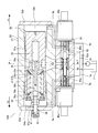
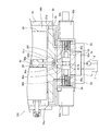
図1及び図2に示すように、サーボレギュレータ100は、ピストンポンプ1の斜板3にアーム10を介して連結されるサーボピストン20と、サーボピストン20に作用する作動油の圧力を制御するスプール30と、を備える。スプール30は、第1ソレノイド40a及び第2ソレノイド40bにより移動する。
As shown in FIGS. 1 and 2, the servo regulator 100 includes a servo piston 20 connected to the swash plate 3 of the piston pump 1 via an arm 10, and a spool that controls the pressure of hydraulic oil acting on the servo piston 20. 30. The spool 30 is moved by the first solenoid 40a and the second solenoid 40b.
サーボピストン20及びスプール30は、ケース50内に収容される。ケース50は、ピストンポンプ1のハウジング2に取り付けられる第1ケース部材51と、第1ケース部材51に取り付けられる第2ケース部材52と、を有する。
Servo piston 20 and spool 30 are accommodated in case 50. The case 50 has a first case member 51 attached to the housing 2 of the piston pump 1 and a second case member 52 attached to the first case member 51.
第1ケース部材51には第1収容孔51aが形成され、第2ケース部材52には第2収容孔52aが形成される。第2ケース部材52が第1ケース部材51に取り付けられた状態では、第1収容孔51aと第2収容孔52aとは略平行である。第1収容孔51aにはサーボピストン20が摺動自在に収容され、第2収容孔52aにはスプール30が収容される。
The first case member 51 has a first accommodation hole 51a, and the second case member 52 has a second accommodation hole 52a. In a state where the second case member 52 is attached to the first case member 51, the first accommodation hole 51a and the second accommodation hole 52a are substantially parallel. The servo piston 20 is slidably accommodated in the first accommodation hole 51a, and the spool 30 is accommodated in the second accommodation hole 52a.
第1収容孔51aの両開口端は、それぞれ第1カバー53a及び第2カバー53bにより閉塞される。第1収容孔51aの内部には、サーボピストン20により第1圧力室54aと第2圧力室54bとが区画される。具体的には、第1圧力室54aは、第1収容孔51aの内周面、サーボピストン20の一方の端面及び第1カバー53aにより画定され、サーボピストン20の一方の端面に面して設けられる。同様に、第2圧力室54bは、第1収容孔51aの内周面、サーボピストン20の他方の端面及び第2カバー53bにより画定され、サーボピストン20の他方の端面に面して設けられる。
Both opening ends of the first accommodation hole 51a are closed by the first cover 53a and the second cover 53b, respectively. The first pressure chamber 54a and the second pressure chamber 54b are partitioned by the servo piston 20 inside the first accommodation hole 51a. Specifically, the first pressure chamber 54a is defined by the inner peripheral surface of the first accommodation hole 51a, one end surface of the servo piston 20, and the first cover 53a, and is provided to face one end surface of the servo piston 20. It is done. Similarly, the second pressure chamber 54b is defined by the inner peripheral surface of the first accommodation hole 51a, the other end surface of the servo piston 20 and the second cover 53b, and is provided to face the other end surface of the servo piston 20.
サーボピストン20は、第1圧力室54a及び第2圧力室54b内の作動油の圧力により第1収容孔51a内を移動する。第1圧力室54a内の圧力が第2圧力室54b内の圧力よりも大きいときには、サーボピストン20は、第1圧力室54aを拡大し第2圧力室54bを縮小するP1方向(図2における右方向)に移動する。第2圧力室54b内の圧力が第1圧力室54a内の圧力よりも大きいときには、サーボピストン20は、第2圧力室54bを拡大し第1圧力室54aを縮小するP2方向(図2における左方向)に移動する。
The servo piston 20 moves in the first accommodation hole 51a by the pressure of the hydraulic oil in the first pressure chamber 54a and the second pressure chamber 54b. When the pressure in the first pressure chamber 54a is larger than the pressure in the second pressure chamber 54b, the servo piston 20 expands the first pressure chamber 54a and contracts the second pressure chamber 54b (right side in FIG. 2). Direction). When the pressure in the second pressure chamber 54b is larger than the pressure in the first pressure chamber 54a, the servo piston 20 expands the second pressure chamber 54b and reduces the first pressure chamber 54a (the left side in FIG. 2). Direction).
サーボピストン20は、第1カバー53aに固定されるガイドロッド56によりガイドされる。サーボピストン20のロッド側端部には、ガイドロッド56の外周に取り付けられる第1リテーナ57a及び第2リテーナ57bを収容可能な収容凹部21が形成される。また、サーボピストン20には、収容凹部21の底面21aから軸方向に延びるガイド孔22が形成される。
Servo piston 20 is guided by guide rod 56 fixed to first cover 53a. An accommodation recess 21 capable of accommodating the first retainer 57 a and the second retainer 57 b attached to the outer periphery of the guide rod 56 is formed at the rod side end of the servo piston 20. Further, the servo piston 20 is formed with a guide hole 22 extending in the axial direction from the bottom surface 21 a of the housing recess 21.
ガイドロッド56とサーボピストン20は同軸上に配置される。ガイドロッド56の先端部56aは、軸部56bよりも拡径されており、サーボピストン20のガイド孔22に摺動自在に挿入されている。
The guide rod 56 and the servo piston 20 are arranged on the same axis. The distal end portion 56 a of the guide rod 56 has a diameter larger than that of the shaft portion 56 b and is slidably inserted into the guide hole 22 of the servo piston 20.
ガイドロッド56の軸部56bには、第1リテーナ57a及び第2リテーナ57bが摺動自在に設けられている。第1リテーナ57aと第2リテーナ57bとの間には、第1ピストンスプリング59a及び第2ピストンスプリング59bが圧縮状態で設けられている。第1ピストンスプリング59a及び第2ピストンスプリング59bは、サーボピストン20を中立位置に付勢する。
A first retainer 57a and a second retainer 57b are slidably provided on the shaft portion 56b of the guide rod 56. A first piston spring 59a and a second piston spring 59b are provided in a compressed state between the first retainer 57a and the second retainer 57b. The first piston spring 59a and the second piston spring 59b urge the servo piston 20 to the neutral position.
図2に示すように、サーボピストン20が中立位置にある場合には、第1リテーナ57aは、収容凹部21の開口端に固定されたストッパリング23に当接するとともに、軸部56bに螺合するナット61に当接している。第2リテーナ57bは、サーボピストン20の収容凹部21の底面21aに当接するとともに、ガイドロッド56の先端部56aと軸部56bとの間に形成される段部56cに当接する。
As shown in FIG. 2, when the servo piston 20 is in the neutral position, the first retainer 57a abuts on the stopper ring 23 fixed to the opening end of the housing recess 21 and is screwed into the shaft portion 56b. It is in contact with the nut 61. The second retainer 57b abuts on the bottom surface 21a of the housing recess 21 of the servo piston 20 and abuts on a step portion 56c formed between the distal end portion 56a of the guide rod 56 and the shaft portion 56b.
サーボピストン20が中立位置からP1方向に移動すると、第1リテーナ57aは、サーボピストン20に固定されるストッパリング23により押される。その結果、第1リテーナ57aは、ガイドロッド56の軸部56bに螺合するナット61から離れるようにガイドロッド56の軸部56bに沿って移動する。
When the servo piston 20 moves in the P1 direction from the neutral position, the first retainer 57a is pushed by the stopper ring 23 fixed to the servo piston 20. As a result, the first retainer 57a moves along the shaft portion 56b of the guide rod 56 so as to be separated from the nut 61 screwed into the shaft portion 56b of the guide rod 56.
このとき、第2リテーナ57bはガイドロッド56の段部56cに当接し、ガイドロッド56に対して移動しない。したがって、第1リテーナ57aと第2リテーナ57bとの間の第1ピストンスプリング59a及び第2ピストンスプリング59bが圧縮され、サーボピストン20を中立位置に戻そうとするスプリング反力が大きくなる。
At this time, the second retainer 57b comes into contact with the step portion 56c of the guide rod 56 and does not move relative to the guide rod 56. Therefore, the first piston spring 59a and the second piston spring 59b between the first retainer 57a and the second retainer 57b are compressed, and the spring reaction force for returning the servo piston 20 to the neutral position is increased.
一方、サーボピストン20が中立位置からP2方向に移動すると、第2リテーナ57bは、サーボピストン20の底面21aにより押される。その結果、第2リテーナ57bは、ガイドロッド56の段部56cから離れるようにガイドロッド56の軸部56bに沿って移動する。
On the other hand, when the servo piston 20 moves in the P2 direction from the neutral position, the second retainer 57b is pushed by the bottom surface 21a of the servo piston 20. As a result, the second retainer 57 b moves along the shaft portion 56 b of the guide rod 56 so as to be separated from the step portion 56 c of the guide rod 56.
このとき、第1リテーナ57aはナット61に当接し、ガイドロッド56に対して移動しない。したがって、第1リテーナ57aと第2リテーナ57bとの間の第1ピストンスプリング59a及び第2ピストンスプリング59bが圧縮され、サーボピストン20を中立位置に戻そうとするスプリング反力が大きくなる。
At this time, the first retainer 57a contacts the nut 61 and does not move relative to the guide rod 56. Therefore, the first piston spring 59a and the second piston spring 59b between the first retainer 57a and the second retainer 57b are compressed, and the spring reaction force for returning the servo piston 20 to the neutral position is increased.
なお、第1カバー53aに対するガイドロッド56の締結位置を調整し、ナット62を介してガイドロッド56を第1カバー53aに固定することで、サーボピストン20の中立位置を調整することができる。
The neutral position of the servo piston 20 can be adjusted by adjusting the fastening position of the guide rod 56 with respect to the first cover 53a and fixing the guide rod 56 to the first cover 53a via the nut 62.
図1及び図2に示すように、サーボピストン20の軸方向中央の外周には、環状溝24が形成されている。環状溝24には、アーム10が連結される。
As shown in FIGS. 1 and 2, an annular groove 24 is formed on the outer periphery of the center of the servo piston 20 in the axial direction. The arm 10 is connected to the annular groove 24.
具体的には、アーム10の先端にはピン12が設けられ、ピン12にスライドメタル13が回転自在に支持されている。スライドメタル13は、サーボピストン20の環状溝24内に挿入される。
Specifically, a pin 12 is provided at the tip of the arm 10, and a slide metal 13 is rotatably supported by the pin 12. The slide metal 13 is inserted into the annular groove 24 of the servo piston 20.
このように、アーム10は、ピン12及びスライドメタル13を介して環状溝24に連結される。なお、図2では、アーム10、ピン12及びスライドメタル13の図示を省略している。
Thus, the arm 10 is connected to the annular groove 24 through the pin 12 and the slide metal 13. 2, illustration of the arm 10, the pin 12, and the slide metal 13 is omitted.
サーボピストン20が移動すると、スライドメタル13がサーボピストン20とともに移動する。その結果、アーム10が回動中心軸3Cを中心に回動し、斜板3が傾転する。このように、サーボピストン20の変位は、アーム10を介して斜板3に伝達される。斜板3の傾転により、ピストンポンプ1の吐出流量が変化する。
When the servo piston 20 moves, the slide metal 13 moves together with the servo piston 20. As a result, the arm 10 rotates about the rotation center shaft 3C, and the swash plate 3 tilts. Thus, the displacement of the servo piston 20 is transmitted to the swash plate 3 via the arm 10. As the swash plate 3 tilts, the discharge flow rate of the piston pump 1 changes.
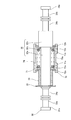
図2及び図3に示すように、第2収容孔52aの両端位置には、円筒状の第1スリーブ80a及び第2スリーブ80bが設けられる。第1スリーブ80aは、供給通路5aを介して油圧ポンプ(油圧源)5に接続される供給ポート81aと、メイン通路6aを介して第1圧力室54aに接続されるメインポート82aと、を有する。第2スリーブ80bは、供給通路5bを介して油圧ポンプ5(油圧源)に接続される供給ポート81bと、メイン通路6bを介して第2圧力室54bに接続されるメインポート82bと、を有する。
2 and 3, a cylindrical first sleeve 80a and a second sleeve 80b are provided at both end positions of the second accommodation hole 52a. The first sleeve 80a has a supply port 81a connected to the hydraulic pump (hydraulic power source) 5 through the supply passage 5a, and a main port 82a connected to the first pressure chamber 54a through the main passage 6a. . The second sleeve 80b has a supply port 81b connected to the hydraulic pump 5 (hydraulic power source) via the supply passage 5b, and a main port 82b connected to the second pressure chamber 54b via the main passage 6b. .
第2収容孔52aの内周面には、タンク7に接続されるドレン通路7a,7bが開口する。ドレン通路7a,7bの開口は、第1スリーブ80aと第2スリーブ80bとの間に位置する。
Drain passages 7a and 7b connected to the tank 7 are opened on the inner peripheral surface of the second accommodation hole 52a. The openings of the drain passages 7a and 7b are located between the first sleeve 80a and the second sleeve 80b.
第2収容孔52aの略中央位置には、スプリングホルダ(保持部材)70が設けられる。スプリングホルダ70は、スプール30を付勢するスプールスプリング(付勢部材)71を保持する。スプールスプリング71は、コイルバネである。
A spring holder (holding member) 70 is provided at a substantially central position of the second accommodation hole 52a. The spring holder 70 holds a spool spring (biasing member) 71 that biases the spool 30. The spool spring 71 is a coil spring.
スプリングホルダ70は、スプールスプリング71を収容する略筒状のホルダ本体(収容部)70aと、ホルダ本体70aの内周に設けられる第1スナップリング(第5支持部)72a及び第2スナップリング(第6支持部)72bと、を有する。ホルダ本体70aの外径は、第2ケース部材52の第2収容孔52aの内径と略等しく、第2収容孔52aを摺動する。
The spring holder 70 includes a substantially cylindrical holder main body (accommodating portion) 70a for accommodating the spool spring 71, a first snap ring (fifth support portion) 72a and a second snap ring (on the inner periphery of the holder main body 70a). 6th support part) 72b. The outer diameter of the holder body 70a is substantially equal to the inner diameter of the second accommodation hole 52a of the second case member 52, and slides in the second accommodation hole 52a.
第1スナップリング72aは、ホルダ本体70aの一方の開口端近傍に着脱可能に設けられ、第2スナップリング72bは、ホルダ本体70aの他方の開口端近傍に着脱可能に設けられる。スプールスプリング71は、第1スナップリング72aと第2スナップリング72bとの間に設けられる。
The first snap ring 72a is detachably provided near one opening end of the holder body 70a, and the second snap ring 72b is detachably provided near the other opening end of the holder body 70a. The spool spring 71 is provided between the first snap ring 72a and the second snap ring 72b.
第1スナップリング72aとスプールスプリング71の一方の端部71aとの間には環状の第1リテーナ(第3支持部)73aが設けられ、第2スナップリング72bとスプールスプリング71の他方の端部71bとの間には環状の第2リテーナ(第4支持部)73bが設けられる。スプールスプリング71は、第1リテーナ73aと第2リテーナ73bとの間に圧縮された状態で設けられる。換言すれば、第1リテーナ73aは、スプールスプリング71の一方の端部71aを支持し、第2リテーナ73bは、スプールスプリング71の他方の端部71bを支持する。
An annular first retainer (third support) 73 a is provided between the first snap ring 72 a and one end 71 a of the spool spring 71, and the other end of the second snap ring 72 b and the spool spring 71 is provided. An annular second retainer (fourth support portion) 73b is provided between the two and 71b. The spool spring 71 is provided in a compressed state between the first retainer 73a and the second retainer 73b. In other words, the first retainer 73 a supports one end 71 a of the spool spring 71, and the second retainer 73 b supports the other end 71 b of the spool spring 71.
スプール30は、第1圧力室54a内の圧力を制御する第1制御部31aと、第2圧力室54b内の圧力を制御する第2制御部31bと、第1制御部31aと第2制御部31bとを連結する連結部32と、を有する。第1制御部31a、第2制御部31b及び連結部32は一体的に形成される。
The spool 30 includes a first control unit 31a that controls the pressure in the first pressure chamber 54a, a second control unit 31b that controls the pressure in the second pressure chamber 54b, a first control unit 31a, and a second control unit. And a connecting portion 32 that connects 31b. The 1st control part 31a, the 2nd control part 31b, and the connection part 32 are integrally formed.
第1制御部31aは、第1スリーブ80a内に摺動自在に挿入される。第2制御部31bは、第2スリーブ80b内に摺動自在に挿入される。連結部32は、スプールスプリング71を挿通する。
The first control unit 31a is slidably inserted into the first sleeve 80a. The second control unit 31b is slidably inserted into the second sleeve 80b. The connecting portion 32 is inserted through the spool spring 71.
スプール30の第1制御部31aの外周には、環状溝33a及び環状溝34aが形成される。環状溝33aはスプール30の位置に応じて供給ポート81aとメインポート82aとを接続し、環状溝34aはメインポート82aとドレン通路7aとを接続する。
An annular groove 33a and an annular groove 34a are formed on the outer periphery of the first control portion 31a of the spool 30. The annular groove 33a connects the supply port 81a and the main port 82a according to the position of the spool 30, and the annular groove 34a connects the main port 82a and the drain passage 7a.
スプール30の第2制御部31bの外周には、環状溝33b及び環状溝34bが形成される。環状溝33bはスプール30の位置に応じて供給ポート81bとメインポート82bとを接続し、環状溝34bはメインポート82bとドレン通路7bとを接続する。
An annular groove 33b and an annular groove 34b are formed on the outer periphery of the second control portion 31b of the spool 30. The annular groove 33b connects the supply port 81b and the main port 82b according to the position of the spool 30, and the annular groove 34b connects the main port 82b and the drain passage 7b.
スプール30は、第1ソレノイド40aに設けられる第1プランジャ41aにより押されることで第1制御部31aから第2制御部31bに向かうS1方向(第1方向)に移動する。スプール30がS1方向に移動すると環状溝33aは供給ポート81aとメインポート82aとを接続するので、第1圧力室54aには油圧ポンプ5から吐出される作動油が供給される。つまり、S1方向は、第1圧力室54aの圧力を上昇させる方向である。
The spool 30 moves in the S1 direction (first direction) from the first control unit 31a toward the second control unit 31b by being pushed by the first plunger 41a provided in the first solenoid 40a. When the spool 30 moves in the S1 direction, the annular groove 33a connects the supply port 81a and the main port 82a, so that the hydraulic oil discharged from the hydraulic pump 5 is supplied to the first pressure chamber 54a. That is, the S1 direction is a direction in which the pressure in the first pressure chamber 54a is increased.
また、スプール30は、第2ソレノイド40bに設けられる第2プランジャ41bにより押されることで第2制御部31bから第1制御部31aに向かうS2方向(第2方向)に移動する。スプール30がS2方向に移動すると環状溝33bは供給ポート81bとメインポート82bとを接続するので、第2圧力室54bには油圧ポンプ5から吐出される作動油が供給される。つまり、S2方向は、第2圧力室54bの圧力を上昇させる方向である。
Further, the spool 30 moves in the S2 direction (second direction) from the second control unit 31b toward the first control unit 31a by being pushed by the second plunger 41b provided in the second solenoid 40b. When the spool 30 moves in the S2 direction, the annular groove 33b connects the supply port 81b and the main port 82b, so that hydraulic oil discharged from the hydraulic pump 5 is supplied to the second pressure chamber 54b. That is, the S2 direction is a direction in which the pressure in the second pressure chamber 54b is increased.
第1ソレノイド40a及び第2ソレノイド40bは、付与される電流値に比例して第1プランジャ41a及び第2プランジャ41bの推力(吸引力)が変化する比例型ソレノイドである。第1ソレノイド40a及び第2ソレノイド40bは、第2収容孔52aの開口端を閉塞するように第2ケース部材52に取り付けられる。第1ソレノイド40a,第2ソレノイド40bは、それぞれ、配線を介して、図示しないコントローラに接続されている。
The first solenoid 40a and the second solenoid 40b are proportional solenoids in which the thrust (suction force) of the first plunger 41a and the second plunger 41b changes in proportion to the applied current value. The first solenoid 40a and the second solenoid 40b are attached to the second case member 52 so as to close the open end of the second accommodation hole 52a. The first solenoid 40a and the second solenoid 40b are each connected to a controller (not shown) via wiring.
第1ソレノイド40a及び第2ソレノイド40bが非駆動状態である場合には、スプール30は初期位置に位置している。このとき、スプール30の第1制御部31aと第1プランジャ41aとは所定の間隔(初期間隔)をあけて対向している。また、スプール30の第2制御部31bと第2プランジャ41bとは所定の間隔(初期間隔)をあけて対向している。
When the first solenoid 40a and the second solenoid 40b are not driven, the spool 30 is located at the initial position. At this time, the first controller 31a of the spool 30 and the first plunger 41a are opposed to each other with a predetermined interval (initial interval). Further, the second control portion 31b of the spool 30 and the second plunger 41b face each other with a predetermined interval (initial interval).
スプール30の連結部32は、小径部(挿通部)32aと、小径部32aの外径よりも大きい外径を有する大径部(第2支持部)32bと、を有する。小径部32aは第1制御部31aから連続して形成され、大径部32bは第2制御部31bから連続して形成される。小径部32aと大径部32bとの間には段部32cが形成される。
The connecting portion 32 of the spool 30 includes a small diameter portion (insertion portion) 32a and a large diameter portion (second support portion) 32b having an outer diameter larger than the outer diameter of the small diameter portion 32a. The small diameter portion 32a is formed continuously from the first control portion 31a, and the large diameter portion 32b is formed continuously from the second control portion 31b. A step 32c is formed between the small diameter portion 32a and the large diameter portion 32b.
小径部32aには第1リテーナ73a及び第2リテーナ73bが設けられる。つまり、小径部32aは、第1リテーナ73a、スプールスプリング71及び第2リテーナ73bを挿通する。小径部32aの外径は、第1リテーナ73a及び第2リテーナ73bの内径と略等しく、第1リテーナ73a及び第2リテーナ73bは小径部32aの外周を摺動する。
A first retainer 73a and a second retainer 73b are provided in the small diameter portion 32a. That is, the small diameter portion 32a is inserted through the first retainer 73a, the spool spring 71, and the second retainer 73b. The outer diameter of the small diameter portion 32a is substantially equal to the inner diameter of the first retainer 73a and the second retainer 73b, and the first retainer 73a and the second retainer 73b slide on the outer periphery of the small diameter portion 32a.
第1リテーナ73aに対してスプールスプリング71とは反対側には、円筒状のカラー(第1支持部)36が設けられる。スプール30の小径部32aにおける第1制御部31aの近傍にはスナップリング35が固定され、スナップリング35によって、小径部32aからのカラー36の抜けが防止される。スナップリング35をスプール30から取り外すことによって、カラー36をスプール30から取り外すことができる。このように、カラー36は、スプール30に着脱可能に設けられる。
A cylindrical collar (first support portion) 36 is provided on the side opposite to the spool spring 71 with respect to the first retainer 73a. A snap ring 35 is fixed in the vicinity of the first control portion 31a in the small diameter portion 32a of the spool 30, and the snap ring 35 prevents the collar 36 from coming off from the small diameter portion 32a. The collar 36 can be removed from the spool 30 by removing the snap ring 35 from the spool 30. As described above, the collar 36 is detachably provided on the spool 30.
カラー36の外径は第1リテーナ73aの内径よりも大きく、カラー36は、第1制御部31aに近づく方向への第1リテーナ73a及びスプールスプリング71の移動を制限する。カラー36の外径は、第1スナップリング72a及びホルダ本体70aの内径よりも小さく、第1スナップリング72a及びホルダ本体70aは、カラー36により制限されることなくスプール30に対して相対移動可能である。
The outer diameter of the collar 36 is larger than the inner diameter of the first retainer 73a, and the collar 36 restricts the movement of the first retainer 73a and the spool spring 71 in the direction approaching the first control unit 31a. The outer diameter of the collar 36 is smaller than the inner diameters of the first snap ring 72a and the holder main body 70a, and the first snap ring 72a and the holder main body 70a are movable relative to the spool 30 without being limited by the collar 36. is there.
スプール30の大径部32bの外径は第2リテーナ73bの内径よりも大きく、大径部32bは、第2制御部31bに近づく方向への第2リテーナ73b及びスプールスプリング71の移動を制限する。大径部32bの外径は、第2スナップリング72b及びホルダ本体70aの内径よりも小さく、第2スナップリング72b及びホルダ本体70aは、大径部32bにより制限されることなくスプール30に対して相対移動可能である。
The outer diameter of the large diameter portion 32b of the spool 30 is larger than the inner diameter of the second retainer 73b, and the large diameter portion 32b restricts the movement of the second retainer 73b and the spool spring 71 in the direction approaching the second control portion 31b. . The outer diameter of the large diameter portion 32b is smaller than the inner diameters of the second snap ring 72b and the holder main body 70a, and the second snap ring 72b and the holder main body 70a are not limited by the large diameter portion 32b and are not limited to the spool 30. Relative movement is possible.
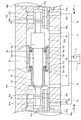
図4に示すように、スプリングホルダ70がスプール30に対して第1制御部31aに近づく方向に移動すると、第2リテーナ73bは第2スナップリング72bにより押される。第2リテーナ73bは連結部32の段部32cから離れ、小径部32aに沿ってスプール30に対して相対移動する。
As shown in FIG. 4, when the spring holder 70 moves in a direction approaching the first control unit 31a with respect to the spool 30, the second retainer 73b is pushed by the second snap ring 72b. The second retainer 73b moves away from the step portion 32c of the connecting portion 32 and moves relative to the spool 30 along the small diameter portion 32a.
このとき、第1リテーナ73aはカラー36の端面に当接し、連結部32に対して移動しない。したがって、第1リテーナ73aと第2リテーナ73bとの間でスプールスプリング71が圧縮される。その結果、スプールスプリング71の反力が大きくなる。
At this time, the first retainer 73a contacts the end face of the collar 36 and does not move relative to the connecting portion 32. Therefore, the spool spring 71 is compressed between the first retainer 73a and the second retainer 73b. As a result, the reaction force of the spool spring 71 increases.
第2リテーナ73bが段部32cから離れる一方で第1リテーナ73aがカラー36の端面に当接するので、スプールスプリング71の反力は、第1リテーナ73a、カラー36及びスナップリング35を介してスプール30に伝わる。したがって、スプール30は、スプールスプリング71により、供給ポート81aとメインポート82aとの連通を遮断する方向に付勢される。
Since the first retainer 73a abuts against the end surface of the collar 36 while the second retainer 73b is separated from the stepped portion 32c, the reaction force of the spool spring 71 is applied to the spool 30 via the first retainer 73a, the collar 36 and the snap ring 35. It is transmitted to. Accordingly, the spool 30 is urged by the spool spring 71 in a direction that blocks communication between the supply port 81a and the main port 82a.
このように、カラー36は、スプリングホルダ70がスプール30に対して第1制御部31aに近づく方向に移動するときにスプールスプリング71の一方の端部71aを第1リテーナ73aを介して支持する第1支持部として機能する。第2リテーナ73bは、スプールスプリング71の他方の端部71bを支持してスプール30に対して相対移動する第4支持部として機能する。第2スナップリング72bは、スプールスプリング71の他方の端部71bを第2リテーナ73bを介して支持する第6支持部として機能する。
As described above, the collar 36 supports the one end 71a of the spool spring 71 via the first retainer 73a when the spring holder 70 moves in a direction approaching the first control unit 31a with respect to the spool 30. 1 Functions as a support part. The second retainer 73 b functions as a fourth support portion that supports the other end portion 71 b of the spool spring 71 and moves relative to the spool 30. The second snap ring 72b functions as a sixth support portion that supports the other end portion 71b of the spool spring 71 via the second retainer 73b.
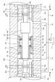
一方、図5に示すように、スプリングホルダ70がスプール30に対して第2制御部31bに近づく方向に移動すると、第1リテーナ73aは第1スナップリング72aにより押される。第1リテーナ73aはカラー36の端面から離れ、小径部32aに沿ってスプール30に対して相対移動する。
On the other hand, as shown in FIG. 5, when the spring holder 70 moves in the direction approaching the second controller 31b with respect to the spool 30, the first retainer 73a is pushed by the first snap ring 72a. The first retainer 73a moves away from the end face of the collar 36 and moves relative to the spool 30 along the small diameter portion 32a.
このとき、第2リテーナ73bは段部32cに当接し、連結部32に対して移動しない。したがって、第1リテーナ73aと第2リテーナ73bとの間でスプールスプリング71が圧縮される。その結果、スプールスプリング71の反力が大きくなる。
At this time, the second retainer 73b contacts the stepped portion 32c and does not move with respect to the connecting portion 32. Therefore, the spool spring 71 is compressed between the first retainer 73a and the second retainer 73b. As a result, the reaction force of the spool spring 71 increases.
第1リテーナ73aがカラー36の端面から離れる一方で第2リテーナ73bが段部32cに当接するので、スプールスプリング71の反力は、第2リテーナ73bを介してスプール30に伝わる。したがって、スプール30は、スプールスプリング71により、供給ポート81bとメインポート82bとの連通を遮断する方向に付勢される。
Since the first retainer 73a is separated from the end face of the collar 36, the second retainer 73b is in contact with the stepped portion 32c, so that the reaction force of the spool spring 71 is transmitted to the spool 30 via the second retainer 73b. Therefore, the spool 30 is urged by the spool spring 71 in a direction that blocks the communication between the supply port 81b and the main port 82b.
このように、大径部32bは、スプリングホルダ70がスプール30に対して第2制御部31bに近づく方向に移動するときにスプールスプリング71の他方の端部71bを第2リテーナ73bを介して支持する第2支持部として機能する。第1リテーナ73aは、スプールスプリング71の一方の端部71aを支持してスプール30に対して相対移動する第3支持部として機能する。第1スナップリング72aは、スプールスプリング71の一方の端部71aを第1リテーナ73aを介して支持する第5支持部として機能する。
Thus, the large diameter portion 32b supports the other end 71b of the spool spring 71 via the second retainer 73b when the spring holder 70 moves in a direction approaching the second control portion 31b with respect to the spool 30. It functions as a second support part. The first retainer 73 a functions as a third support portion that supports one end portion 71 a of the spool spring 71 and moves relative to the spool 30. The first snap ring 72a functions as a fifth support portion that supports one end 71a of the spool spring 71 via the first retainer 73a.
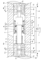
図1及び図6に示すように、サーボレギュレータ100は、サーボピストン20の変位をスプリングホルダ70に伝達するフィードバックリンク90と、フィードバックリンク90を回動可能に支持する支持シャフト91と、を更に備える。
As shown in FIGS. 1 and 6, the servo regulator 100 further includes a feedback link 90 that transmits the displacement of the servo piston 20 to the spring holder 70, and a support shaft 91 that rotatably supports the feedback link 90. .
フィードバックリンク90は、サーボピストン20とスプリングホルダ70との間に亘って延在する。具体的には、第1ケース部材51には、第1収容孔51aの内周面に開口する第1挿通孔51bが形成され、第2ケース部材52には、第2収容孔52aの内周面に開口する第2挿通孔52bが形成される。第1挿通孔51bと第2挿通孔52bとは連続しており、フィードバックリンク90は第1挿通孔51b及び第2挿通孔52bを通じてサーボピストン20とスプリングホルダ70との間に亘って延在する。
The feedback link 90 extends between the servo piston 20 and the spring holder 70. Specifically, the first case member 51 is formed with a first insertion hole 51b that opens to the inner peripheral surface of the first accommodation hole 51a, and the second case member 52 has an inner circumference of the second accommodation hole 52a. A second insertion hole 52b that opens to the surface is formed. The first insertion hole 51b and the second insertion hole 52b are continuous, and the feedback link 90 extends between the servo piston 20 and the spring holder 70 through the first insertion hole 51b and the second insertion hole 52b. .
フィードバックリンク90の第1端部90aは、サーボピストン20の環状溝24に挿入される。これによって、フィードバックリンク90がサーボピストン20に連結される。
The first end 90a of the feedback link 90 is inserted into the annular groove 24 of the servo piston 20. As a result, the feedback link 90 is connected to the servo piston 20.
フィードバックリンク90の第1端部90aは、サーボピストン20の中心軸に対してスライドメタル13とは反対側に位置する。また、フィードバックリンク90は、環状溝24の接線方向に延在し、フィードバックリンク90の一部は、サーボピストン20を横切るように環状溝24内に配置される。
The first end 90 a of the feedback link 90 is located on the opposite side of the slide metal 13 with respect to the central axis of the servo piston 20. The feedback link 90 extends in the tangential direction of the annular groove 24, and a part of the feedback link 90 is disposed in the annular groove 24 so as to cross the servo piston 20.
フィードバックリンク90の第2端部90bは、スプリングホルダ70に連結される。具体的には、スプリングホルダ70のホルダ本体70aの外周には環状溝74が形成され、第2端部90bは環状溝74に挿入される。
The second end 90 b of the feedback link 90 is connected to the spring holder 70. Specifically, an annular groove 74 is formed on the outer periphery of the holder main body 70 a of the spring holder 70, and the second end 90 b is inserted into the annular groove 74.
このように、フィードバックリンク90はサーボピストン20に連結されるとともにスプリングホルダ70に連結される。サーボピストン20がアーム10を介して斜板3に連結されるので、フィードバックリンク90は、サーボピストン20及びアーム10を介して斜板3に連結される。同様に、スプリングホルダ70は、フィードバックリンク90、サーボピストン20及びアーム10を介して斜板3に連結される。
Thus, the feedback link 90 is connected to the servo piston 20 and to the spring holder 70. Since the servo piston 20 is connected to the swash plate 3 via the arm 10, the feedback link 90 is connected to the swash plate 3 via the servo piston 20 and the arm 10. Similarly, the spring holder 70 is connected to the swash plate 3 via the feedback link 90, the servo piston 20 and the arm 10.
また、フィードバックリンク90は、第1端部90aと第2端部90bとの間に位置する中間部90cと、第1端部90aと中間部90cとを連結する連結部90dと、第2端部90bと中間部90cとを連結する連結部90eと、を有する。中間部90cには孔90fが形成される。
The feedback link 90 includes an intermediate portion 90c positioned between the first end portion 90a and the second end portion 90b, a connecting portion 90d that connects the first end portion 90a and the intermediate portion 90c, and a second end portion. A connecting portion 90e that connects the portion 90b and the intermediate portion 90c. A hole 90f is formed in the intermediate portion 90c.
支持シャフト91は、フィードバックリンク90の孔90fを挿通した状態で、第1ケース部材51に固定される。換言すれば、フィードバックリンク90は、支持シャフト91を介して第1ケース部材51に回動自在に支持される。サーボピストン20とスプリングホルダ70とがフィードバックリンク90を介して連結されるので、サーボピストン20が移動し、フィードバックリンク90が回動すると、スプリングホルダ70は、サーボピストン20の移動方向とは反対方向に移動する。
The support shaft 91 is fixed to the first case member 51 while being inserted through the hole 90f of the feedback link 90. In other words, the feedback link 90 is rotatably supported by the first case member 51 via the support shaft 91. Since the servo piston 20 and the spring holder 70 are connected via the feedback link 90, when the servo piston 20 moves and the feedback link 90 rotates, the spring holder 70 moves in a direction opposite to the moving direction of the servo piston 20. Move to.
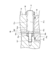
図7に示すように、支持シャフト91は、第1ケース部材51に形成される穴51cに固定される。穴51cは、第1ケース部材51の側面に開口する第1穴部51dと、第1穴部51dの底面51eに開口する第2穴部51fと、を有する。
As shown in FIG. 7, the support shaft 91 is fixed to a hole 51 c formed in the first case member 51. The hole 51c has a first hole 51d that opens to the side surface of the first case member 51, and a second hole 51f that opens to the bottom surface 51e of the first hole 51d.
第1穴部51dは、第1ケース部材51の第1挿通孔51bと交差する。第2穴部51fは第1穴部51dと同軸に形成され、第2穴部51fの内周には雌ネジが形成される。第1穴部51dの底面51eには、ブッシュ51gが配置される。ブッシュ51gの外径は、第1穴部51dの内径と略等しく、ブッシュ51gの内径は、第2穴部51fの内径と略等しい。なお、ブッシュ51gの外径は、第1穴部51dの内径と等しくなくてもよく、第1穴部51dに挿入できる大きさであればよい。
The first hole 51d intersects the first insertion hole 51b of the first case member 51. The second hole 51f is formed coaxially with the first hole 51d, and a female screw is formed on the inner periphery of the second hole 51f. A bush 51g is disposed on the bottom surface 51e of the first hole 51d. The outer diameter of the bush 51g is substantially equal to the inner diameter of the first hole 51d, and the inner diameter of the bush 51g is substantially equal to the inner diameter of the second hole 51f. The outer diameter of the bush 51g does not have to be equal to the inner diameter of the first hole 51d as long as it can be inserted into the first hole 51d.
支持シャフト91は、第1穴部51dを挿通する基部91aと、基部91aと同軸に形成される先端部91bと、基部91a及び先端部91bに対して偏心する偏心部91cと、を有する。先端部91bの外径は基部91aの外径よりも小さい。偏心部91cの外径は、基部91aの外径よりも小さく、先端部91bの外径よりも大きい。
The support shaft 91 includes a base 91a that is inserted through the first hole 51d, a tip 91b that is formed coaxially with the base 91a, and an eccentric portion 91c that is eccentric with respect to the base 91a and the tip 91b. The outer diameter of the tip 91b is smaller than the outer diameter of the base 91a. The outer diameter of the eccentric part 91c is smaller than the outer diameter of the base part 91a and larger than the outer diameter of the tip part 91b.
先端部91bの外周には雄ネジが形成され、第2穴部51fの雌ネジと螺合する。基部91aは、第1穴部51dから第1ケース部材51の外側に突出する。基部91aの外周には雄ネジが形成され、固定ナット96が基部91aの外周に螺合する。支持シャフト91は、第2穴部51fの雌ネジと先端部91bの雄ネジとを螺合させた状態で固定ナット96を締めることにより、第1ケース部材51に固定される。
A male screw is formed on the outer periphery of the tip 91b and is screwed with the female screw of the second hole 51f. The base 91a protrudes outside the first case member 51 from the first hole 51d. A male screw is formed on the outer periphery of the base portion 91a, and the fixing nut 96 is screwed onto the outer periphery of the base portion 91a. The support shaft 91 is fixed to the first case member 51 by tightening the fixing nut 96 in a state where the female screw of the second hole 51f and the male screw of the tip 91b are screwed together.
偏心部91cは、基部91aと先端部91bとの間に設けられ、第1ケース部材51の第1挿通孔51b内に位置する。偏心部91cの外径はフィードバックリンク90の孔90fの内径と略等しく、偏心部91cが孔90fを挿通する。つまり、フィードバックリンク90は、偏心部91cの中心軸周りに回動可能に支持される。
The eccentric part 91 c is provided between the base part 91 a and the tip part 91 b and is located in the first insertion hole 51 b of the first case member 51. The outer diameter of the eccentric part 91c is substantially equal to the inner diameter of the hole 90f of the feedback link 90, and the eccentric part 91c passes through the hole 90f. That is, the feedback link 90 is supported so as to be rotatable around the central axis of the eccentric portion 91c.
前述のように、偏心部91cは、基部91a及び先端部91bに対して偏心する。そのため、第1ケース部材51に対して支持シャフト91を回転させると、偏心部91cの中心が変位する。その結果、フィードバックリンク90の孔90fの中心、すなわちフィードバックリンク90の回動中心軸が変位する。
As described above, the eccentric portion 91c is eccentric with respect to the base portion 91a and the distal end portion 91b. Therefore, when the support shaft 91 is rotated with respect to the first case member 51, the center of the eccentric portion 91c is displaced. As a result, the center of the hole 90f of the feedback link 90, that is, the rotation center axis of the feedback link 90 is displaced.
図6に示すように、フィードバックリンク90は、サーボピストン20及びスプリングホルダ70に連結される。そのため、フィードバックリンク90の回動中心の変位に伴って、サーボピストン20及びスプリングホルダ70が変位する。
As shown in FIG. 6, the feedback link 90 is connected to the servo piston 20 and the spring holder 70. Therefore, the servo piston 20 and the spring holder 70 are displaced with the displacement of the rotation center of the feedback link 90.
第1ピストンスプリング59a及び第2ピストンスプリング59b(図2参照)のバネ定数は、スプリングホルダ70の内周に設けられるスプールスプリング71(図3参照)のバネ定数よりも大きい。そのため、サーボピストン20の変位量は、スプリングホルダ70の変位量よりも小さい。つまり、フィードバックリンク90の回動中心の変位は、主に、スプリングホルダ70を変位させる。スプリングホルダ70の変位によって、スプールスプリング71が移動し、スプール30の中立位置が変化する。
The spring constants of the first piston spring 59a and the second piston spring 59b (see FIG. 2) are larger than the spring constant of the spool spring 71 (see FIG. 3) provided on the inner periphery of the spring holder 70. Therefore, the displacement amount of the servo piston 20 is smaller than the displacement amount of the spring holder 70. That is, the displacement of the rotation center of the feedback link 90 mainly displaces the spring holder 70. Due to the displacement of the spring holder 70, the spool spring 71 moves, and the neutral position of the spool 30 changes.
このように、サーボレギュレータ100では、支持シャフト91を回転させることにより、スプール30の中立位置を調整することができる。
Thus, in the servo regulator 100, the neutral position of the spool 30 can be adjusted by rotating the support shaft 91.
次に、図1~図5を参照して、サーボレギュレータ100の動作について説明する。
Next, the operation of the servo regulator 100 will be described with reference to FIGS.
運転者が車両を後進させるように車両のコントロールレバーを操作すると、コントロールレバーの操作量に応じた電流が第1ソレノイド40aに付与され、第1ソレノイド40aの第1プランジャ41aが初期位置にあるスプール30をS1方向に移動させる(図4参照)。
When the driver operates the control lever of the vehicle to move the vehicle backward, a current corresponding to the operation amount of the control lever is applied to the first solenoid 40a, and the first plunger 41a of the first solenoid 40a is in the initial position. 30 is moved in the S1 direction (see FIG. 4).
図2及び図4に示すように、スプール30が第1プランジャ41aによりS1方向に移動すると、第1制御部31aの環状溝33aが供給ポート81aとメインポート82aとを接続する。油圧ポンプ5から吐出された作動油は、供給ポート81a、環状溝33a、メインポート82a及びメイン通路6aを通って第1圧力室54aに導かれる。
2 and 4, when the spool 30 is moved in the S1 direction by the first plunger 41a, the annular groove 33a of the first controller 31a connects the supply port 81a and the main port 82a. The hydraulic oil discharged from the hydraulic pump 5 is guided to the first pressure chamber 54a through the supply port 81a, the annular groove 33a, the main port 82a, and the main passage 6a.
第2制御部31bは連結部32により第1制御部31aと連結されているので、第2制御部31bは第1制御部31aが移動する方向に移動する。このとき、第2制御部31bは供給ポート81bとメインポート82bとの連通を遮断する一方で、メインポート82bとドレン通路7bとを接続する。そのため、第2圧力室54bには、ドレン通路7b及びメインポート82bを通じてタンク圧が導かれる。
Since the second control unit 31b is connected to the first control unit 31a by the connecting unit 32, the second control unit 31b moves in the direction in which the first control unit 31a moves. At this time, the second control unit 31b blocks the communication between the supply port 81b and the main port 82b, and connects the main port 82b and the drain passage 7b. Therefore, the tank pressure is guided to the second pressure chamber 54b through the drain passage 7b and the main port 82b.
第1圧力室54aにパイロット圧が導かれ第2圧力室54bにタンク圧が導かれることで、サーボピストン20が第1ピストンスプリング59a及び第2ピストンスプリング59bの付勢力に抗して中立位置からP1方向に移動する。サーボピストン20の環状溝24にスライドメタル13(図1参照)が挿入されているので、スライドメタル13(図1参照)がP1方向に移動し、アーム10が回動する。
The pilot pressure is guided to the first pressure chamber 54a and the tank pressure is guided to the second pressure chamber 54b, so that the servo piston 20 is moved from the neutral position against the urging force of the first piston spring 59a and the second piston spring 59b. Move in the P1 direction. Since the slide metal 13 (see FIG. 1) is inserted into the annular groove 24 of the servo piston 20, the slide metal 13 (see FIG. 1) moves in the P1 direction, and the arm 10 rotates.
アーム10の回動に伴って、ピストンポンプ1の斜板3が一方に傾転し、斜板3の傾転角度が変化する。その結果、ピストンポンプ1から走行用モータに作動油が供給され、走行用油圧モータが逆転して車両が後進する。
As the arm 10 rotates, the swash plate 3 of the piston pump 1 tilts to one side, and the tilt angle of the swash plate 3 changes. As a result, hydraulic oil is supplied from the piston pump 1 to the traveling motor, and the traveling hydraulic motor reverses and the vehicle moves backward.
図6に示すように、サーボピストン20の環状溝24にはフィードバックリンク90の第1端部90aが挿入されているので、サーボピストン20がP1方向に移動すると、第1端部90aはP1方向に移動する。第1端部90aの移動によりフィードバックリンク90が回動し、フィードバックリンク90の第2端部90bが移動する。その結果、スプリングホルダ70がS2方向に移動する。
As shown in FIG. 6, since the first end 90a of the feedback link 90 is inserted into the annular groove 24 of the servo piston 20, when the servo piston 20 moves in the P1 direction, the first end 90a moves in the P1 direction. Move to. The feedback link 90 is rotated by the movement of the first end 90a, and the second end 90b of the feedback link 90 is moved. As a result, the spring holder 70 moves in the S2 direction.
図4に示すように、スプリングホルダ70がスプール30に対してS2方向に移動すると、第2スナップリング72bが第2リテーナ73bをS2方向に移動させる。第2リテーナ73bはスプール30の段部32cから離れるので、スプールスプリング71の端部71bは、第2リテーナ73bを介して第2スナップリング72bにより支持される。
As shown in FIG. 4, when the spring holder 70 moves in the S2 direction with respect to the spool 30, the second snap ring 72b moves the second retainer 73b in the S2 direction. Since the second retainer 73b is separated from the step portion 32c of the spool 30, the end 71b of the spool spring 71 is supported by the second snap ring 72b via the second retainer 73b.
一方で、第1リテーナ73aはカラー36の端面に当接し、スプール30に対して移動しない。第1リテーナ73aは第1スナップリング72aから離れるので、スプールスプリング71の端部71aは、第1リテーナ73aを介してカラー36により支持される。
On the other hand, the first retainer 73 a abuts against the end face of the collar 36 and does not move with respect to the spool 30. Since the first retainer 73a is separated from the first snap ring 72a, the end 71a of the spool spring 71 is supported by the collar 36 through the first retainer 73a.
カラー36はスプール30とともにS1方向に移動する一方で、第2スナップリング72bがスプール30に対してS2方向に相対移動するので、スプールスプリング71は、第1リテーナ73aと第2リテーナ73bとにより圧縮される。その結果、スプール30を初期位置に戻そうとするスプールスプリング71の反力(付勢力)が増加する。
While the collar 36 moves in the S1 direction together with the spool 30, the second snap ring 72b moves relative to the spool 30 in the S2 direction, so that the spool spring 71 is compressed by the first retainer 73a and the second retainer 73b. Is done. As a result, the reaction force (biasing force) of the spool spring 71 that attempts to return the spool 30 to the initial position increases.
このように、フィードバックリンク90は、サーボピストン20の移動すなわち斜板3の傾転角度の変化に応じてスプールスプリング71の付勢力を変化させる。
Thus, the feedback link 90 changes the urging force of the spool spring 71 in accordance with the movement of the servo piston 20, that is, the change in the tilt angle of the swash plate 3.
スプールスプリング71の付勢力が変化すると、スプールスプリング71の付勢力と、第1ソレノイド40aの第1プランジャ41aの推力とが釣り合うようにスプール30が移動する。これにより、第1圧力室54a内の作動油圧は、サーボピストン20を所望の位置で保つように調整される。その結果、サーボピストン20も所定位置で停止し、ピストンポンプ1の斜板3の傾転角度が所望の所定角度に維持される。
When the urging force of the spool spring 71 changes, the spool 30 moves so that the urging force of the spool spring 71 and the thrust of the first plunger 41a of the first solenoid 40a are balanced. Thereby, the hydraulic pressure in the first pressure chamber 54a is adjusted so as to keep the servo piston 20 at a desired position. As a result, the servo piston 20 also stops at a predetermined position, and the tilt angle of the swash plate 3 of the piston pump 1 is maintained at a desired predetermined angle.
一方、運転者が車両を前進させるようにコントロールレバーを操作すると、コントロールレバーの操作量に応じた電流が第2ソレノイド40bに付与され、第2ソレノイド40bの第2プランジャ41bがスプール30をS2方向に移動させる(図5参照)。
On the other hand, when the driver operates the control lever to advance the vehicle, a current corresponding to the operation amount of the control lever is applied to the second solenoid 40b, and the second plunger 41b of the second solenoid 40b causes the spool 30 to move in the S2 direction. (See FIG. 5).
スプール30が第2プランジャ41bによりS2方向に移動すると、第2制御部31bの環状溝33bが供給ポート81bとメインポート82bとを接続する。油圧ポンプ5から吐出された作動油は、供給ポート81b、環状溝33b、メインポート82b及びメイン通路6bを通って第2圧力室54bに導かれる。
When the spool 30 is moved in the S2 direction by the second plunger 41b, the annular groove 33b of the second control unit 31b connects the supply port 81b and the main port 82b. The hydraulic oil discharged from the hydraulic pump 5 is guided to the second pressure chamber 54b through the supply port 81b, the annular groove 33b, the main port 82b, and the main passage 6b.
第1制御部31aは連結部32により第2制御部31bと連結されているので、第1制御部31aは第2制御部31bが移動する方向に移動する。このとき、第1制御部31aは供給ポート81aとメインポート82aとの連通を遮断する一方で、メインポート82aとドレン通路7aとを接続する。そのため、第1圧力室54aには、ドレン通路7a及びメインポート82aを通じてタンク圧が導かれる。
Since the first control unit 31a is connected to the second control unit 31b by the connecting unit 32, the first control unit 31a moves in the direction in which the second control unit 31b moves. At this time, the first control unit 31a blocks the communication between the supply port 81a and the main port 82a, and connects the main port 82a and the drain passage 7a. Therefore, the tank pressure is guided to the first pressure chamber 54a through the drain passage 7a and the main port 82a.
第2圧力室54bにパイロット圧が導かれ、第1圧力室54aにタンク圧が導かれることで、サーボピストン20が第1ピストンスプリング59a及び第2ピストンスプリング59bの付勢力に抗して図2の中立位置からP2方向に移動する。スライドメタル13(図1参照)がP2方向に移動し、アーム10が回動する。その結果、ピストンポンプ1の斜板3が他方に傾転し、走行用油圧モータが正転して、車両が前進する。
The pilot pressure is guided to the second pressure chamber 54b and the tank pressure is guided to the first pressure chamber 54a, so that the servo piston 20 resists the urging force of the first piston spring 59a and the second piston spring 59b. Move in the P2 direction from the neutral position. The slide metal 13 (see FIG. 1) moves in the P2 direction, and the arm 10 rotates. As a result, the swash plate 3 of the piston pump 1 tilts to the other, the traveling hydraulic motor rotates forward, and the vehicle moves forward.
図6に示すように、サーボピストン20の環状溝24にはフィードバックリンク90の第1端部90aが挿入されているので、サーボピストン20がP2方向に移動すると、フィードバックリンク90の第1端部90aがP2方向に移動する。第1端部90aの移動によりフィードバックリンク90が回動し、フィードバックリンク90の第2端部90bが移動する。その結果、スプリングホルダ70がS1方向に移動する。
As shown in FIG. 6, since the first end 90a of the feedback link 90 is inserted into the annular groove 24 of the servo piston 20, when the servo piston 20 moves in the P2 direction, the first end of the feedback link 90 is moved. 90a moves in the P2 direction. The feedback link 90 is rotated by the movement of the first end 90a, and the second end 90b of the feedback link 90 is moved. As a result, the spring holder 70 moves in the S1 direction.
図5に示すように、スプリングホルダ70がスプール30に対してS1方向に移動すると、第1スナップリング72aが第1リテーナ73aをS1方向に移動させる。第1リテーナ73aはカラー36から離れるので、スプールスプリング71の端部71aは、第1リテーナ73aを介して第1スナップリング72aにより支持される。
As shown in FIG. 5, when the spring holder 70 moves in the S1 direction with respect to the spool 30, the first snap ring 72a moves the first retainer 73a in the S1 direction. Since the first retainer 73a is separated from the collar 36, the end 71a of the spool spring 71 is supported by the first snap ring 72a via the first retainer 73a.
一方で、第2リテーナ73bはスプール30の段部32cに当接し、スプール30に対して移動しない。第2リテーナ73bは第2スナップリング72bから離れるので、スプールスプリング71の端部71bは、第2リテーナ73bを介してスプール30の大径部32bにより支持される。
On the other hand, the second retainer 73b abuts against the stepped portion 32c of the spool 30 and does not move relative to the spool 30. Since the second retainer 73b is separated from the second snap ring 72b, the end 71b of the spool spring 71 is supported by the large diameter portion 32b of the spool 30 via the second retainer 73b.
スプール30の大径部32bはスプール30とともにS2方向に移動する一方で、第1スナップリング72aがスプール30に対してS1方向に相対移動するので、スプールスプリング71は、第1リテーナ73aと第2リテーナ73bとにより圧縮される。その結果、スプール30を初期位置に戻そうとするスプールスプリング71の反力(付勢力)が増加する。
While the large diameter portion 32b of the spool 30 moves in the S2 direction together with the spool 30, the first snap ring 72a moves relative to the spool 30 in the S1 direction, so that the spool spring 71 is connected to the first retainer 73a and the second retainer 73a. It is compressed by the retainer 73b. As a result, the reaction force (biasing force) of the spool spring 71 that attempts to return the spool 30 to the initial position increases.
このように、フィードバックリンク90は、サーボピストン20の移動すなわち斜板3の傾転角度の変化に応じてスプールスプリング71の付勢力を変化させる。
Thus, the feedback link 90 changes the urging force of the spool spring 71 in accordance with the movement of the servo piston 20, that is, the change in the tilt angle of the swash plate 3.
そして、スプールスプリング71の付勢力によりスプール30が移動し、第2圧力室54b内の圧力はサーボピストン20を所望の位置に保つように調整される。これにより、ピストンポンプ1の斜板3の傾転角度が所望の角度に維持される。
Then, the spool 30 is moved by the urging force of the spool spring 71, and the pressure in the second pressure chamber 54b is adjusted so as to keep the servo piston 20 at a desired position. Thereby, the tilt angle of the swash plate 3 of the piston pump 1 is maintained at a desired angle.
サーボレギュレータ100によれば、第1ソレノイド40a、第2ソレノイド40bによってスプール30を駆動し、第1圧力室54a及び第2圧力室54b内の圧力を制御して、サーボピストン20の位置を変更することで、ピストンポンプ1の斜板3の傾転を制御することができる。
According to the servo regulator 100, the spool 30 is driven by the first solenoid 40a and the second solenoid 40b, and the position of the servo piston 20 is changed by controlling the pressure in the first pressure chamber 54a and the second pressure chamber 54b. Thus, the tilt of the swash plate 3 of the piston pump 1 can be controlled.
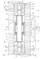
次に、サーボレギュレータ100の組立方法について、図8を参照して説明する。ここでは、主に、スプール30にスプールスプリング71を組み付ける方法について説明する。
Next, a method for assembling the servo regulator 100 will be described with reference to FIG. Here, a method of assembling the spool spring 71 to the spool 30 will be mainly described.
まず、図8に示すように、第2スナップリング72bが固定されたホルダ本体70aにスプール30を挿入する。次に、第2リテーナ73bをスプール30の小径部32aの外周に配置し、ホルダ本体70aに挿入する。
First, as shown in FIG. 8, the spool 30 is inserted into the holder body 70a to which the second snap ring 72b is fixed. Next, the 2nd retainer 73b is arrange | positioned on the outer periphery of the small diameter part 32a of the spool 30, and it inserts in the holder main body 70a.
スプールスプリング71及び第1リテーナ73aをスプール30の小径部32aの外周に配置し、ホルダ本体70aに挿入する。このとき、カラー36がスプール30から取り外されているので、スプールスプリング71及び第1リテーナ73aを変形させることなくスプール30に組み付けることができる。また、ホルダ本体70aから第1スナップリング72aが取り外されているので、スプールスプリング71及び第1リテーナ73aを変形させることなくスプール30に組み付けることができる。その後、第1スナップリング72aをホルダ本体70aに固定する。
The spool spring 71 and the first retainer 73a are arranged on the outer periphery of the small diameter portion 32a of the spool 30 and inserted into the holder main body 70a. At this time, since the collar 36 is removed from the spool 30, the spool spring 71 and the first retainer 73a can be assembled to the spool 30 without being deformed. Further, since the first snap ring 72a is removed from the holder body 70a, the spool spring 71 and the first retainer 73a can be assembled to the spool 30 without being deformed. Thereafter, the first snap ring 72a is fixed to the holder body 70a.
カラー36にスプール30を挿入し、カラー36を小径部32aの外周に配置する。その後、スナップリング35を小径部32aに固定する。スナップリング35によって、小径部32aからのカラー36の抜けが防止される。
The spool 30 is inserted into the collar 36, and the collar 36 is arranged on the outer periphery of the small diameter portion 32a. Thereafter, the snap ring 35 is fixed to the small diameter portion 32a. The snap ring 35 prevents the collar 36 from coming off from the small diameter portion 32a.
以上により、スプール30へのスプールスプリング71の組み付けが完了する。
Thus, the assembly of the spool spring 71 to the spool 30 is completed.
サーボレギュレータ100では、カラー36がスプール30に着脱可能に設けられる。そのため、サーボレギュレータ100を組み立てる際には、カラー36をスプール30から取り外すことにより、一体化されたスプール30に、スプールスプリング71を変形させることなく組み付けることができる。したがって、スプールスプリング71の特性が変化するのを防止することができ、所望の制御特性を得ることができる。
In the servo regulator 100, the collar 36 is detachably provided on the spool 30. Therefore, when the servo regulator 100 is assembled, the collar 36 can be detached from the spool 30 and can be assembled to the integrated spool 30 without deforming the spool spring 71. Therefore, it is possible to prevent the characteristics of the spool spring 71 from changing, and to obtain desired control characteristics.
また、スプール30は単一の部品として形成されるので、スプール30の移動により油圧ポンプ5と第1圧力室54aとが接続された場合には、第2圧力室54bは所定の大きさの開口を有する通路を通じてタンク7と接続される。そのため、第1圧力室54aの圧力の上昇に伴って、第2圧力室54bとタンク7との間を流れる作動油の流量の変動を軽減することができ、サーボレギュレータ100の動作を安定させることができる。
Further, since the spool 30 is formed as a single component, when the hydraulic pump 5 and the first pressure chamber 54a are connected by the movement of the spool 30, the second pressure chamber 54b is opened to a predetermined size. It connects with the tank 7 through the channel | path which has. Therefore, as the pressure in the first pressure chamber 54a increases, fluctuations in the flow rate of the hydraulic fluid flowing between the second pressure chamber 54b and the tank 7 can be reduced, and the operation of the servo regulator 100 can be stabilized. Can do.
また、サーボレギュレータ100では、スプール30がS2方向に移動するときには、スプールスプリング71の他方の端部71bがスプール30の大径部32bにより支持され、スプールスプリング71の一方の端部71aがサーボピストン20の移動に応じてスプール30に対して相対移動する第1スナップリング72aにより支持される。そのため、スプール30は、S1方向に移動するときとS2方向に移動するときの両方で1つのスプールスプリング71により付勢される。したがって、スプールスプリング71の特性のばらつきに起因する制御特性のばらつきを軽減することができる。
In the servo regulator 100, when the spool 30 moves in the S2 direction, the other end 71b of the spool spring 71 is supported by the large-diameter portion 32b of the spool 30, and the one end 71a of the spool spring 71 is the servo piston. It is supported by a first snap ring 72a that moves relative to the spool 30 in accordance with the movement of 20. Therefore, the spool 30 is biased by one spool spring 71 both when moving in the S1 direction and when moving in the S2 direction. Therefore, variations in control characteristics due to variations in characteristics of the spool spring 71 can be reduced.
また、スプリングホルダ70は、スプールスプリング71の両端部71a,71bにより第1リテーナ73a及び第2リテーナ73bを介して位置決めされる。そのため、スプリングホルダ70に対するスプール30の移動に伴って第1リテーナ73a又は第2リテーナ73bによりスプールスプリング71を圧縮してスプールスプリング71の付勢力を増大させることができる。したがって、スプール30がS1方向に移動するときとS2方向に移動するときとの両方で1つのスプールスプリング71によりスプール30を付勢することができ、制御特性のばらつきを軽減することができる。
Further, the spring holder 70 is positioned by both end portions 71a and 71b of the spool spring 71 via the first retainer 73a and the second retainer 73b. Therefore, as the spool 30 moves with respect to the spring holder 70, the spool spring 71 can be compressed by the first retainer 73a or the second retainer 73b, and the urging force of the spool spring 71 can be increased. Therefore, the spool 30 can be urged by one spool spring 71 both when the spool 30 moves in the S1 direction and when it moves in the S2 direction, and variations in control characteristics can be reduced.
また、第1スナップリング72aがホルダ本体70aに着脱可能に設けられる。そのため、サーボレギュレータ100を組み立てる際には、第1スナップリング72aをホルダ本体70aから取り外すことにより、ホルダ本体70a内に、スプールスプリング71を変形させることなく収容することができる。したがって、スプールスプリング71の特性が変化するのを防止することができ、サーボレギュレータ100の動作の安定性を向上させることができる。
The first snap ring 72a is detachably provided on the holder body 70a. Therefore, when the servo regulator 100 is assembled, the spool spring 71 can be accommodated in the holder body 70a without being deformed by removing the first snap ring 72a from the holder body 70a. Therefore, the characteristics of the spool spring 71 can be prevented from changing, and the operation stability of the servo regulator 100 can be improved.
なお、サーボレギュレータ100では、第1スナップリング72a及び第2スナップリング72bの両方がホルダ本体70aに着脱可能に設けられる。第2スナップリング72bは、ホルダ本体70aに着脱不能に設けられていてもよい。つまり、第1スナップリング72a及び第2スナップリング72bの少なくとも一方がホルダ本体70aに着脱可能に設けられていればよい。
In the servo regulator 100, both the first snap ring 72a and the second snap ring 72b are detachably provided on the holder body 70a. The 2nd snap ring 72b may be provided in the holder main body 70a so that attachment or detachment is impossible. That is, it is sufficient that at least one of the first snap ring 72a and the second snap ring 72b is detachably provided on the holder body 70a.
また、サーボレギュレータ100では、大径部32bが第2支持部として機能する。そのため、第2支持部をスプール30に一体的に形成することができる。したがって、部品数を削減することができ、サーボレギュレータ100の動作の安定性を向上させつつサーボレギュレータ100の組立性を向上させることができる。
In the servo regulator 100, the large diameter portion 32b functions as a second support portion. Therefore, the second support portion can be formed integrally with the spool 30. Therefore, the number of parts can be reduced, and the assemblability of the servo regulator 100 can be improved while improving the stability of the operation of the servo regulator 100.
なお、本実施形態では、小径部32aと大径部32bの間に段部32cが形成されているが、段部32cが形成されていなくてもよい。例えば、大径部32bは、外径が小径部32aから徐々に拡大するようにテーパ状に形成されていてもよい。
In this embodiment, the step portion 32c is formed between the small diameter portion 32a and the large diameter portion 32b, but the step portion 32c may not be formed. For example, the large diameter part 32b may be formed in a tapered shape so that the outer diameter gradually increases from the small diameter part 32a.
<第2実施形態>
次に、本発明の第2実施形態に係るサーボレギュレータ200について、図9を参照して説明する。第1実施形態に係るサーボレギュレータ100と同一の構成については同一の符号を付し、その説明を省略する。 Second Embodiment
Next, aservo regulator 200 according to a second embodiment of the present invention will be described with reference to FIG. The same components as those of the servo regulator 100 according to the first embodiment are denoted by the same reference numerals, and the description thereof is omitted.
次に、本発明の第2実施形態に係るサーボレギュレータ200について、図9を参照して説明する。第1実施形態に係るサーボレギュレータ100と同一の構成については同一の符号を付し、その説明を省略する。 Second Embodiment
Next, a
図9は、第2実施形態に係るサーボレギュレータ200の断面図であり、図3に対応して示す。サーボレギュレータ200では、連結部232に大径部32b(図3参照)が形成されておらず、カラー(第2支持部)236が連結部232の外周に設けられている。
FIG. 9 is a cross-sectional view of the servo regulator 200 according to the second embodiment, corresponding to FIG. In the servo regulator 200, the connecting portion 232 is not formed with the large diameter portion 32 b (see FIG. 3), and the collar (second support portion) 236 is provided on the outer periphery of the connecting portion 232.
スプール230の連結部232における第2制御部31bの近傍にはスナップリング235が固定され、スナップリング235によって、連結部232からのカラー236の抜けが防止される。スナップリング235をスプール230から取り外すことによって、カラー236をスプール230から取り外すことができる。このように、カラー236は、スプール230に着脱可能に設けられる。
A snap ring 235 is fixed in the vicinity of the second control portion 31b in the connecting portion 232 of the spool 230, and the snap ring 235 prevents the collar 236 from coming off from the connecting portion 232. The collar 236 can be removed from the spool 230 by removing the snap ring 235 from the spool 230. Thus, the collar 236 is detachably provided on the spool 230.
サーボレギュレータ200では、カラー36に加え、カラー236がスプール230に着脱可能に設けられる。そのため、サーボレギュレータ200を組み立てる際には、カラー36及びカラー236の両方をスプール230から取り外すことにより、スプール230に、スプールスプリング71を変形させることなくスプール230の両端から組み付けることができる。したがって、スプールスプリング71の特性が変化するのを防止することができるとともに、サーボレギュレータ200の組立性を向上させることができる。
In the servo regulator 200, in addition to the collar 36, a collar 236 is detachably provided on the spool 230. Therefore, when assembling the servo regulator 200, both the collar 36 and the collar 236 are removed from the spool 230, so that the spool 230 can be assembled from both ends of the spool 230 without deforming the spool spring 71. Therefore, it is possible to prevent the characteristics of the spool spring 71 from changing, and to improve the assemblability of the servo regulator 200.
以下、本発明の実施形態の構成、作用、及び効果をまとめて説明する。
Hereinafter, the configuration, operation, and effect of the embodiment of the present invention will be described together.
本実施形態では、サーボレギュレータ100,200は、ケース50内に摺動自在に収容されるサーボピストン20と、サーボピストン20の両端部に面して設けられる第1圧力室54a及び第2圧力室54bと、第1ソレノイド40a及び第2ソレノイド40bにより移動して第1圧力室54a及び第2圧力室54b内の圧力を制御するスプール30,230と、スプール30,230の外周に設けられ、第1ソレノイド40a及び第2ソレノイド40bの推力に抗してスプール30,230を付勢するスプールスプリング71と、スプール30,230に設けられ、スプール30,230が第1圧力室54a内の圧力を上昇させるS1方向に移動するときにスプールスプリング71の一方の端部71aを支持するカラー36と、スプール30,230に設けられ、スプール30,230が第2圧力室54b内の圧力を上昇させるS2方向に移動するときにスプールスプリング71の他方の端部71bを支持する大径部32b及びカラー236と、を備え、カラー36、並びに大径部32b及びカラー236の少なくとも一方は、スプール30,230に着脱可能に設けられる。
In the present embodiment, the servo regulators 100 and 200 include the servo piston 20 slidably accommodated in the case 50, and a first pressure chamber 54a and a second pressure chamber provided facing both ends of the servo piston 20. 54b, spools 30 and 230 that are moved by the first solenoid 40a and the second solenoid 40b to control the pressure in the first pressure chamber 54a and the second pressure chamber 54b, and are provided on the outer periphery of the spools 30 and 230. A spool spring 71 that urges the spools 30 and 230 against the thrust of the first solenoid 40a and the second solenoid 40b, and the spools 30 and 230 are provided to increase the pressure in the first pressure chamber 54a. A collar 36 that supports one end 71a of the spool spring 71 when moving in the S1 direction, and a spool A large-diameter portion 32b and a collar 236 that are provided at 30, 230 and support the other end 71b of the spool spring 71 when the spool 30, 230 moves in the S2 direction to increase the pressure in the second pressure chamber 54b. The collar 36 and at least one of the large diameter portion 32b and the collar 236 are detachably provided on the spools 30 and 230.
この構成では、カラー36、並びに大径部32b及びカラー236の少なくとも一方がスプール30,230に着脱可能に設けられる。そのため、サーボレギュレータ100,200を組み立てる際には、カラー36、並びに大径部32b及びカラー236の少なくとも一方をスプール30,230から取り外すことにより、一体化されたスプール30,230に、スプールスプリング71を変形させることなく組み付けることができる。したがって、スプール30,230を一体化するとともにスプールスプリング71の特性が変化するのを防止することができ、サーボレギュレータ100,200の動作の安定性を向上させることができる。
In this configuration, the collar 36 and at least one of the large diameter portion 32 b and the collar 236 are detachably provided on the spools 30 and 230. Therefore, when the servo regulators 100 and 200 are assembled, the spool 36 is removed from the spools 30 and 230 by removing at least one of the collar 36 and the large diameter portion 32b and the collar 236 from the spools 30 and 230. Can be assembled without deforming. Therefore, the spools 30 and 230 can be integrated and the characteristics of the spool spring 71 can be prevented from changing, and the operation stability of the servo regulators 100 and 200 can be improved.
また、本実施形態では、サーボレギュレータ100,200は、カラー36とスプールスプリング71の一方の端部71aとの間に設けられ、スプール30,230がS1方向に移動するときとS2方向に移動するときの両方においてスプールスプリング71の一方の端部71aを支持する第1リテーナ73aと、大径部32b及びカラー236とスプールスプリング71の他方の端部71bとの間に設けられ、スプール30,230がS1方向に移動するときとS2方向に移動するときの両方においてスプールスプリング71の他方の端部71bを支持する第2リテーナ73bと、を更に備え、第1リテーナ73aは、スプール30,230がS1方向に移動するときにはスプール30,230とともに移動し、スプール30,230がS2方向に移動するときにはサーボピストン20の移動に応じてスプール30,230に対して相対移動し、第2リテーナ73bは、スプール30,230がS2方向に移動するときにはスプール30,230とともに移動し、スプール30,230がS1方向に移動するときにはサーボピストン20の移動に応じてスプール30,230に対して相対移動し、第1リテーナ73aに対するS2方向へのスプール30,230の相対移動に伴って第1リテーナ73aと第2リテーナ73bとの間でスプールスプリング71が圧縮されてスプールスプリング71の付勢力が増大し、第2リテーナ73bに対するS1方向へのスプール30,230の移動に伴って第1リテーナ73aと第2リテーナ73bとの間でスプールスプリング71が圧縮されてスプールスプリング71の付勢力が増大する。
In this embodiment, the servo regulators 100 and 200 are provided between the collar 36 and one end 71a of the spool spring 71, and move when the spools 30 and 230 move in the S1 direction and in the S2 direction. In both cases, the first retainer 73a that supports one end 71a of the spool spring 71, the large diameter portion 32b and the collar 236, and the other end 71b of the spool spring 71 are provided. And a second retainer 73b that supports the other end 71b of the spool spring 71 both when moving in the S1 direction and when moving in the S2 direction. The first retainer 73a includes the spools 30 and 230. When moving in the S1 direction, it moves together with the spools 30 and 230, and the spools 30 and 230 When moving in two directions, the second retainer 73b moves with the spools 30, 230 when the spools 30, 230 move in the S2 direction. When the spools 30 and 230 move in the S1 direction, the spools 30 and 230 move relative to the spools 30 and 230 according to the movement of the servo piston 20, and the spools 30 and 230 move relative to the first retainer 73a in the S2 direction. The spool spring 71 is compressed between the first retainer 73a and the second retainer 73b to increase the urging force of the spool spring 71, and the first retainer is moved in accordance with the movement of the spools 30 and 230 in the S1 direction with respect to the second retainer 73b. The spool spring 71 is compressed between 73a and the second retainer 73b. Is the biasing force of the spool spring 71 is increased.
この構成では、スプール30,230がS2方向に移動するときには、第1リテーナ73aがサーボピストン20の移動に応じてスプール30,230に対して相対移動し、第1リテーナ73aと第2リテーナ73bとの間でスプールスプリング71が圧縮されてスプールスプリング71の付勢力が増大する。また、スプール30,230がS1方向に移動するときには、第2リテーナ73bがサーボピストン20の移動に応じてスプール30,230に対して相対移動し、第1リテーナ73aと第2リテーナ73bとの間でスプールスプリング71が圧縮されてスプールスプリング71の付勢力が増大する。そのため、スプール30,230は、S1方向に移動するときとS2方向に移動するときの両方で1つのスプールスプリング71により付勢される。したがって、スプールスプリング71の特性のばらつきに起因する制御特性のばらつきを軽減することができる。
In this configuration, when the spools 30 and 230 move in the S2 direction, the first retainer 73a moves relative to the spools 30 and 230 in accordance with the movement of the servo piston 20, and the first retainer 73a and the second retainer 73b During this period, the spool spring 71 is compressed, and the urging force of the spool spring 71 increases. Further, when the spools 30 and 230 move in the S1 direction, the second retainer 73b moves relative to the spools 30 and 230 in accordance with the movement of the servo piston 20, and between the first retainer 73a and the second retainer 73b. Thus, the spool spring 71 is compressed and the urging force of the spool spring 71 is increased. Therefore, the spools 30 and 230 are biased by one spool spring 71 both when moving in the S1 direction and when moving in the S2 direction. Therefore, variations in control characteristics due to variations in characteristics of the spool spring 71 can be reduced.
また、本実施形態では、サーボレギュレータ100,200は、スプールスプリング71を保持し、スプールスプリング71の両端部71a,71bにより第1リテーナ73a及び第2リテーナ73bを介して位置決めされるスプリングホルダ70を更に備える。
In the present embodiment, the servo regulators 100 and 200 hold the spool spring 71 and the spring holder 70 positioned by the both end portions 71a and 71b of the spool spring 71 via the first retainer 73a and the second retainer 73b. In addition.
この構成では、スプリングホルダ70がスプールスプリング71の両端部71a,71bにより第1リテーナ73a及び第2リテーナ73bを介して位置決される。そのため、スプリングホルダ70に対するスプール30,230の移動に伴って第1リテーナ73a又は第2リテーナ73bによりスプールスプリング71を圧縮してスプールスプリング71の付勢力を増大させることができる。したがって、スプール30,230がS1方向に移動するときとS2方向に移動するときとの両方で1つのスプールスプリング71によりスプール30,230を付勢することができ、制御特性のばらつきを軽減することができる。
In this configuration, the spring holder 70 is positioned by the both ends 71a and 71b of the spool spring 71 via the first retainer 73a and the second retainer 73b. Therefore, the urging force of the spool spring 71 can be increased by compressing the spool spring 71 by the first retainer 73a or the second retainer 73b as the spools 30 and 230 move relative to the spring holder 70. Therefore, the spools 30 and 230 can be urged by one spool spring 71 both when the spools 30 and 230 move in the S1 direction and when they move in the S2 direction, thereby reducing variations in control characteristics. Can do.
また、スプリングホルダ70は、スプールスプリング71を収容するホルダ本体70aと、ホルダ本体70aの内周に設けられ、スプール30,230がS2方向に移動するときに第1リテーナ73aを介してスプールスプリング71の一方の端部71aを支持する第1スナップリング72aと、ホルダ本体70aの内周に設けられ、スプール30,230がS1方向に移動するときに第2リテーナ73bを介してスプールスプリング71の他方の端部71bを支持する第2スナップリング72bと、を有し、第1スナップリング72a及び第2スナップリング72bの少なくとも一方は、ホルダ本体70aに着脱可能に設けられる。
The spring holder 70 is provided on a holder main body 70a for accommodating the spool spring 71 and an inner periphery of the holder main body 70a, and the spool spring 71 is interposed via the first retainer 73a when the spools 30 and 230 move in the S2 direction. The first snap ring 72a that supports one end portion 71a of the spool spring 71 and the other end of the spool spring 71 via the second retainer 73b provided on the inner periphery of the holder body 70a and when the spools 30 and 230 move in the S1 direction. And a second snap ring 72b for supporting the end portion 71b of the first and second snap rings 72a and 72b. At least one of the first snap ring 72a and the second snap ring 72b is detachably provided on the holder body 70a.
この構成では、第1スナップリング72a及び第2スナップリング72bの少なくとも一方がホルダ本体70aに着脱可能に設けられる。そのため、サーボレギュレータ100,200を組み立てる際には、第1スナップリング72a及び第2スナップリング72bの少なくとも一方をホルダ本体70aから取り外すことにより、ホルダ本体70a内に、スプールスプリング71を変形させることなく収容することができる。したがって、スプールスプリング71の特性が変化するのを防止することができ、サーボレギュレータ100,200の動作の安定性を向上させることができる。
In this configuration, at least one of the first snap ring 72a and the second snap ring 72b is detachably provided on the holder body 70a. Therefore, when assembling the servo regulators 100 and 200, by removing at least one of the first snap ring 72a and the second snap ring 72b from the holder main body 70a, the spool spring 71 is not deformed in the holder main body 70a. Can be accommodated. Therefore, the characteristics of the spool spring 71 can be prevented from changing, and the operation stability of the servo regulators 100 and 200 can be improved.
また、本実施形態では、スプール30は、スプールスプリング71を挿通する小径部32aと、小径部32aから連続して形成され小径部32aよりも大きい外径を有する大径部32bと、を有し、大径部32bは、スプール30がS2方向に移動するときにスプールスプリング71の他方の端部71bを支持する。
In the present embodiment, the spool 30 includes a small diameter portion 32a through which the spool spring 71 is inserted, and a large diameter portion 32b that is formed continuously from the small diameter portion 32a and has an outer diameter larger than that of the small diameter portion 32a. The large diameter portion 32b supports the other end portion 71b of the spool spring 71 when the spool 30 moves in the S2 direction.
この構成では、大径部32bは、スプール30がS2方向に移動するときにスプールスプリング71の他方の端部71bを支持する。そのため、スプールスプリング71の他方の端部71bを支持する支持部をスプール30に一体的に形成することができる。したがって、部品数を削減することができ、サーボレギュレータ100の動作の安定性を向上させつつサーボレギュレータ100の組立性を向上させることができる。
In this configuration, the large diameter portion 32b supports the other end portion 71b of the spool spring 71 when the spool 30 moves in the S2 direction. Therefore, a support portion that supports the other end portion 71 b of the spool spring 71 can be formed integrally with the spool 30. Therefore, the number of parts can be reduced, and the assemblability of the servo regulator 100 can be improved while improving the stability of the operation of the servo regulator 100.
以上、本発明の実施形態について説明したが、上記実施形態は本発明の適用例の一部を示したに過ぎず、本発明の技術的範囲を上記実施形態の具体的構成に限定する趣旨ではない。
The embodiment of the present invention has been described above. However, the above embodiment only shows a part of application examples of the present invention, and the technical scope of the present invention is limited to the specific configuration of the above embodiment. Absent.
本願は2017年3月17日に日本国特許庁に出願された特願2017-053181に基づく優先権を主張し、この出願の全ての内容は参照により本明細書に組み込まれる。
This application claims priority based on Japanese Patent Application No. 2017-053181 filed with the Japan Patent Office on March 17, 2017, the entire contents of which are incorporated herein by reference.
Claims (5)
- サーボレギュレータであって、
ケース内に摺動自在に収容されるサーボピストンと、
前記サーボピストンの両端部に面して設けられる第1圧力室及び第2圧力室と、
ソレノイドにより移動して前記第1圧力室及び前記第2圧力室内の圧力を制御するスプールと、
前記スプールの外周に設けられ、前記ソレノイドの推力に抗して前記スプールを付勢する付勢部材と、
前記スプールに設けられ、前記スプールが前記第1圧力室内の圧力を上昇させる第1方向に移動するときに前記付勢部材の一方の端部を支持する第1支持部と、
前記スプールに設けられ、前記スプールが前記第2圧力室内の圧力を上昇させる第2方向に移動するときに前記付勢部材の他方の端部を支持する第2支持部と、を備え、
前記第1支持部及び前記第2支持部の少なくとも一方は、前記スプールに着脱可能に設けられるサーボレギュレータ。 A servo regulator,
A servo piston slidably housed in the case;
A first pressure chamber and a second pressure chamber provided facing both ends of the servo piston;
A spool that is moved by a solenoid to control the pressure in the first pressure chamber and the second pressure chamber;
An urging member that is provided on an outer periphery of the spool and urges the spool against a thrust of the solenoid;
A first support that is provided on the spool and supports one end of the biasing member when the spool moves in a first direction that increases the pressure in the first pressure chamber;
A second support portion that is provided on the spool and supports the other end of the biasing member when the spool moves in a second direction that increases the pressure in the second pressure chamber.
A servo regulator in which at least one of the first support part and the second support part is detachably attached to the spool. - 請求項1に記載のサーボレギュレータであって、
前記第1支持部と前記付勢部材の前記一方の端部との間に設けられ、前記スプールが前記第1方向に移動するときと前記第2方向に移動するときの両方において前記付勢部材の前記一方の端部を支持する第3支持部と、
前記第2支持部と前記付勢部材の前記他方の端部との間に設けられ、前記スプールが前記第1方向に移動するときと前記第2方向に移動するときの両方において前記付勢部材の前記他方の端部を支持する第4支持部と、を更に備え、
前記第3支持部は、前記スプールが前記第1方向に移動するときには前記スプールとともに移動し、前記スプールが前記第2方向に移動するときには前記サーボピストンの移動に応じて前記スプールに対して相対移動し、
前記第4支持部は、前記スプールが前記第2方向に移動するときには前記スプールとともに移動し、前記スプールが前記第1方向に移動するときには前記サーボピストンの移動に応じて前記スプールに対して相対移動し、
前記第3支持部に対する前記第2方向への前記スプールの相対移動に伴って前記第3支持部と前記第4支持部との間で前記付勢部材が圧縮されて前記付勢部材の付勢力が増大し、
前記第4支持部に対する前記第1方向への前記スプールの相対移動に伴って前記第3支持部と前記第4支持部との間で前記付勢部材が圧縮されて前記付勢部材の付勢力が増大するサーボレギュレータ。 The servo regulator according to claim 1,
The biasing member is provided between the first support portion and the one end portion of the biasing member, and the biasing member is used both when the spool moves in the first direction and when the spool moves in the second direction. A third support for supporting the one end of the
The biasing member is provided between the second support portion and the other end of the biasing member, and the biasing member is moved both when the spool moves in the first direction and when the spool moves in the second direction. And a fourth support part for supporting the other end of
The third support part moves together with the spool when the spool moves in the first direction, and moves relative to the spool according to the movement of the servo piston when the spool moves in the second direction. And
The fourth support portion moves together with the spool when the spool moves in the second direction, and moves relative to the spool according to the movement of the servo piston when the spool moves in the first direction. And
With the relative movement of the spool in the second direction with respect to the third support portion, the biasing member is compressed between the third support portion and the fourth support portion, and the biasing force of the biasing member Increased,
With the relative movement of the spool in the first direction with respect to the fourth support portion, the biasing member is compressed between the third support portion and the fourth support portion, and the biasing force of the biasing member Servo regulator that increases. - 請求項2に記載のサーボレギュレータであって、
前記付勢部材を保持し、前記付勢部材の両端部により前記第3支持部及び前記第4支持部を介して位置決めされる保持部材を更に備えることを特徴とするサーボレギュレータ。 The servo regulator according to claim 2,
The servo regulator further comprising a holding member that holds the urging member and is positioned by the both ends of the urging member via the third support portion and the fourth support portion. - 請求項3に記載のサーボレギュレータであって、
前記保持部材は、
前記付勢部材を収容する収容部と、
前記収容部の内周に設けられ、前記スプールが前記第2方向に移動するときに前記第3支持部を介して前記付勢部材の前記一方の端部を支持する第5支持部と、
前記収容部の内周に設けられ、前記スプールが前記第1方向に移動するときに前記第4支持部を介して前記付勢部材の前記他方の端部を支持する第6支持部と、を有し、
前記第5支持部及び前記第6支持部の少なくとも一方は、前記収容部に着脱可能に設けられるサーボレギュレータ。 The servo regulator according to claim 3, wherein
The holding member is
An accommodating portion for accommodating the biasing member;
A fifth support portion provided on an inner periphery of the housing portion and supporting the one end portion of the biasing member via the third support portion when the spool moves in the second direction;
A sixth support portion provided on an inner periphery of the housing portion and supporting the other end of the biasing member via the fourth support portion when the spool moves in the first direction; Have
A servo regulator in which at least one of the fifth support part and the sixth support part is detachably provided in the housing part. - 請求項1に記載のサーボレギュレータであって、
前記スプールは、前記付勢部材を挿通する挿通部と、前記挿通部から連続して形成され前記挿通部よりも大きい外径を有する大径部と、を有し、
前記大径部が前記第2支持部であるサーボレギュレータ。 The servo regulator according to claim 1,
The spool includes an insertion portion that inserts the urging member, and a large-diameter portion that is formed continuously from the insertion portion and has an outer diameter larger than the insertion portion.
A servo regulator in which the large-diameter portion is the second support portion.
Priority Applications (3)
| Application Number | Priority Date | Filing Date | Title |
|---|---|---|---|
| CN201880018887.3A CN110431305B (en) | 2017-03-17 | 2018-03-13 | Servo regulator |
| DE112018001428.2T DE112018001428T5 (en) | 2017-03-17 | 2018-03-13 | SERVO-REGULATOR |
| US16/491,404 US11236770B2 (en) | 2017-03-17 | 2018-03-13 | Servo regulator |
Applications Claiming Priority (2)
| Application Number | Priority Date | Filing Date | Title |
|---|---|---|---|
| JP2017-053181 | 2017-03-17 | ||
| JP2017053181A JP6577502B2 (en) | 2017-03-17 | 2017-03-17 | Servo regulator |
Publications (1)
| Publication Number | Publication Date |
|---|---|
| WO2018168884A1 true WO2018168884A1 (en) | 2018-09-20 |
Family
ID=63522234
Family Applications (1)
| Application Number | Title | Priority Date | Filing Date |
|---|---|---|---|
| PCT/JP2018/009822 WO2018168884A1 (en) | 2017-03-17 | 2018-03-13 | Servo regulator |
Country Status (5)
| Country | Link |
|---|---|
| US (1) | US11236770B2 (en) |
| JP (1) | JP6577502B2 (en) |
| CN (1) | CN110431305B (en) |
| DE (1) | DE112018001428T5 (en) |
| WO (1) | WO2018168884A1 (en) |
Families Citing this family (1)
| Publication number | Priority date | Publication date | Assignee | Title |
|---|---|---|---|---|
| JP7441737B2 (en) | 2020-06-16 | 2024-03-01 | 日立建機株式会社 | servo mechanism |
Citations (2)
| Publication number | Priority date | Publication date | Assignee | Title |
|---|---|---|---|---|
| JP2009243435A (en) * | 2008-03-31 | 2009-10-22 | Kayaba Ind Co Ltd | Servo regulator |
| JP2009243430A (en) * | 2008-03-31 | 2009-10-22 | Kayaba Ind Co Ltd | Servo-regulator |
Family Cites Families (17)
| Publication number | Priority date | Publication date | Assignee | Title |
|---|---|---|---|---|
| US2969045A (en) * | 1959-02-26 | 1961-01-24 | Acf Ind Inc | Spool-type valve for use in hydraulic systems |
| US3862643A (en) * | 1973-02-26 | 1975-01-28 | Caterpillar Tractor Co | Pilot pump bleed control for earthmoving scrapers |
| US4024798A (en) * | 1975-05-01 | 1977-05-24 | Caterpillar Tractor Co. | Control valve providing two speed operation for a motor |
| JPH03278206A (en) * | 1990-03-28 | 1991-12-09 | Mitsubishi Electric Corp | Electromagnetic flow rate control device |
| US5205201A (en) * | 1991-08-19 | 1993-04-27 | Sauer, Inc. | Displacement control valve |
| DE4129828C1 (en) * | 1991-09-07 | 1993-04-29 | Mercedes-Benz Aktiengesellschaft, 7000 Stuttgart, De | |
| US5316044A (en) * | 1992-12-07 | 1994-05-31 | Caterpillar Inc. | Hydraulic control valve having a centering spring device |
| US6116276A (en) * | 1998-02-09 | 2000-09-12 | Sturman Bg, Llc | Balance latching fluid valve |
| JP2009138537A (en) * | 2007-12-04 | 2009-06-25 | Hitachi Ltd | Solenoid control valve of variable valve gear |
| JP5592319B2 (en) * | 2011-08-22 | 2014-09-17 | 日立オートモティブシステムズステアリング株式会社 | Integral power steering system |
| JP5822141B2 (en) * | 2012-03-29 | 2015-11-24 | Kyb株式会社 | Servo regulator |
| JP5918688B2 (en) * | 2012-12-11 | 2016-05-18 | 川崎重工業株式会社 | Variable displacement pump regulator |
| JP6278317B2 (en) * | 2015-05-08 | 2018-02-14 | Smc株式会社 | Channel switching unit |
| JP6466282B2 (en) * | 2015-08-12 | 2019-02-06 | 日立建機株式会社 | Regulator of variable capacity hydraulic rotating machine |
| JP2017053181A (en) | 2015-09-11 | 2017-03-16 | 株式会社大林組 | Soundproof structure |
| JP6665983B2 (en) * | 2016-07-26 | 2020-03-13 | Smc株式会社 | Fluid pressure cylinder with booster |
| JP7191297B2 (en) * | 2017-12-08 | 2022-12-19 | Smc株式会社 | servo valve |
-
2017
- 2017-03-17 JP JP2017053181A patent/JP6577502B2/en active Active
-
2018
- 2018-03-13 US US16/491,404 patent/US11236770B2/en active Active
- 2018-03-13 WO PCT/JP2018/009822 patent/WO2018168884A1/en active Application Filing
- 2018-03-13 CN CN201880018887.3A patent/CN110431305B/en active Active
- 2018-03-13 DE DE112018001428.2T patent/DE112018001428T5/en active Pending
Patent Citations (2)
| Publication number | Priority date | Publication date | Assignee | Title |
|---|---|---|---|---|
| JP2009243435A (en) * | 2008-03-31 | 2009-10-22 | Kayaba Ind Co Ltd | Servo regulator |
| JP2009243430A (en) * | 2008-03-31 | 2009-10-22 | Kayaba Ind Co Ltd | Servo-regulator |
Also Published As
| Publication number | Publication date |
|---|---|
| DE112018001428T5 (en) | 2019-12-12 |
| CN110431305B (en) | 2021-08-10 |
| JP6577502B2 (en) | 2019-09-18 |
| JP2018155197A (en) | 2018-10-04 |
| US11236770B2 (en) | 2022-02-01 |
| US20200032778A1 (en) | 2020-01-30 |
| CN110431305A (en) | 2019-11-08 |
Similar Documents
| Publication | Publication Date | Title |
|---|---|---|
| WO2018168882A1 (en) | Servo regulator | |
| JP4997163B2 (en) | Servo regulator | |
| JP4997162B2 (en) | Servo regulator | |
| WO2018168884A1 (en) | Servo regulator | |
| KR101596560B1 (en) | Servo regulator | |
| JP5204531B2 (en) | Servo regulator | |
| EP1760313A1 (en) | Variable displacement swash plate-type hydraulic rotating machine | |
| JP5771119B2 (en) | Work vehicle | |
| WO2017169550A1 (en) | Tilt control device and hydraulic rotation device including same | |
| WO2018168883A1 (en) | Servo regulator | |
| WO2020100359A1 (en) | Hydraulic rotating device | |
| JP2009243409A (en) | Servo regulator | |
| JP2022045200A (en) | Liquid pressure rotating machine | |
| JP4209402B2 (en) | Hydraulic pump control device | |
| JP2022045201A (en) | Liquid pressure rotating machine | |
| JP6756686B2 (en) | Tilt control device for variable displacement hydraulic rotary machine | |
| EP0821163A1 (en) | Apparatus for controlling swash-plate pump and motor | |
| JP2010151051A (en) | Inclined rolling control device for variable displacement type hydraulic pump | |
| US20090199554A1 (en) | Hydraulic Stepless Transmission | |
| JP2001099265A (en) | Hydraulic type continuously variable transmission | |
| JP2009243663A (en) | Servo regulator | |
| JPH0953570A (en) | Input control device for hydraulic pump |
Legal Events
| Date | Code | Title | Description |
|---|---|---|---|
| 121 | Ep: the epo has been informed by wipo that ep was designated in this application |
Ref document number: 18767731 Country of ref document: EP Kind code of ref document: A1 |
|
| DPE1 | Request for preliminary examination filed after expiration of 19th month from priority date (pct application filed from 20040101) | ||
| 122 | Ep: pct application non-entry in european phase |
Ref document number: 18767731 Country of ref document: EP Kind code of ref document: A1 |