WO2018168570A1 - Eyewear - Google Patents
Eyewear Download PDFInfo
- Publication number
- WO2018168570A1 WO2018168570A1 PCT/JP2018/008568 JP2018008568W WO2018168570A1 WO 2018168570 A1 WO2018168570 A1 WO 2018168570A1 JP 2018008568 W JP2018008568 W JP 2018008568W WO 2018168570 A1 WO2018168570 A1 WO 2018168570A1
- Authority
- WO
- WIPO (PCT)
- Prior art keywords
- mode
- control unit
- optical
- changed
- eyewear
- Prior art date
Links
Images


Classifications
-
- G—PHYSICS
- G02—OPTICS
- G02C—SPECTACLES; SUNGLASSES OR GOGGLES INSOFAR AS THEY HAVE THE SAME FEATURES AS SPECTACLES; CONTACT LENSES
- G02C7/00—Optical parts
- G02C7/10—Filters, e.g. for facilitating adaptation of the eyes to the dark; Sunglasses
- G02C7/101—Filters, e.g. for facilitating adaptation of the eyes to the dark; Sunglasses having an electro-optical light valve
-
- G—PHYSICS
- G02—OPTICS
- G02C—SPECTACLES; SUNGLASSES OR GOGGLES INSOFAR AS THEY HAVE THE SAME FEATURES AS SPECTACLES; CONTACT LENSES
- G02C7/00—Optical parts
- G02C7/02—Lenses; Lens systems ; Methods of designing lenses
- G02C7/08—Auxiliary lenses; Arrangements for varying focal length
- G02C7/081—Ophthalmic lenses with variable focal length
- G02C7/083—Electrooptic lenses
-
- G—PHYSICS
- G02—OPTICS
- G02C—SPECTACLES; SUNGLASSES OR GOGGLES INSOFAR AS THEY HAVE THE SAME FEATURES AS SPECTACLES; CONTACT LENSES
- G02C11/00—Non-optical adjuncts; Attachment thereof
- G02C11/10—Electronic devices other than hearing aids
-
- G—PHYSICS
- G02—OPTICS
- G02B—OPTICAL ELEMENTS, SYSTEMS OR APPARATUS
- G02B3/00—Simple or compound lenses
- G02B3/12—Fluid-filled or evacuated lenses
- G02B3/14—Fluid-filled or evacuated lenses of variable focal length
-
- G—PHYSICS
- G02—OPTICS
- G02F—OPTICAL DEVICES OR ARRANGEMENTS FOR THE CONTROL OF LIGHT BY MODIFICATION OF THE OPTICAL PROPERTIES OF THE MEDIA OF THE ELEMENTS INVOLVED THEREIN; NON-LINEAR OPTICS; FREQUENCY-CHANGING OF LIGHT; OPTICAL LOGIC ELEMENTS; OPTICAL ANALOGUE/DIGITAL CONVERTERS
- G02F1/00—Devices or arrangements for the control of the intensity, colour, phase, polarisation or direction of light arriving from an independent light source, e.g. switching, gating or modulating; Non-linear optics
- G02F1/01—Devices or arrangements for the control of the intensity, colour, phase, polarisation or direction of light arriving from an independent light source, e.g. switching, gating or modulating; Non-linear optics for the control of the intensity, phase, polarisation or colour
- G02F1/13—Devices or arrangements for the control of the intensity, colour, phase, polarisation or direction of light arriving from an independent light source, e.g. switching, gating or modulating; Non-linear optics for the control of the intensity, phase, polarisation or colour based on liquid crystals, e.g. single liquid crystal display cells
- G02F1/133—Constructional arrangements; Operation of liquid crystal cells; Circuit arrangements
- G02F1/1333—Constructional arrangements; Manufacturing methods
- G02F1/1347—Arrangement of liquid crystal layers or cells in which the final condition of one light beam is achieved by the addition of the effects of two or more layers or cells
- G02F1/13475—Arrangement of liquid crystal layers or cells in which the final condition of one light beam is achieved by the addition of the effects of two or more layers or cells in which at least one liquid crystal cell or layer is doped with a pleochroic dye, e.g. GH-LC cell
-
- G—PHYSICS
- G02—OPTICS
- G02F—OPTICAL DEVICES OR ARRANGEMENTS FOR THE CONTROL OF LIGHT BY MODIFICATION OF THE OPTICAL PROPERTIES OF THE MEDIA OF THE ELEMENTS INVOLVED THEREIN; NON-LINEAR OPTICS; FREQUENCY-CHANGING OF LIGHT; OPTICAL LOGIC ELEMENTS; OPTICAL ANALOGUE/DIGITAL CONVERTERS
- G02F1/00—Devices or arrangements for the control of the intensity, colour, phase, polarisation or direction of light arriving from an independent light source, e.g. switching, gating or modulating; Non-linear optics
- G02F1/29—Devices or arrangements for the control of the intensity, colour, phase, polarisation or direction of light arriving from an independent light source, e.g. switching, gating or modulating; Non-linear optics for the control of the position or the direction of light beams, i.e. deflection
- G02F1/294—Variable focal length devices
Definitions
- the present invention relates to eyewear.
- Patent Document 1 describes eyewear (glasses) that automatically changes the focal length by controlling an electrical signal to the liquid crystal lens according to the inclination angle of the eyeglass body.
- Patent Document 2 describes eyewear that detects a user's viewing distance, line of sight, or head tilt, and changes the focal length of the lens.
- the light intensity sensor detects the light intensity in the use environment, and based on this, the electrochromic element is controlled to change the transmittance, and further the light intensity of the light source of the image display unit is adjusted.
- Sunglasses to be described.
- the sunglasses as described in Patent Document 3 can adjust the transmittance based on the result detected by the light intensity sensor, but turn on / off the dimming function itself according to the use environment. It cannot be switched automatically. Therefore, eyewear capable of switching modes for changing optical characteristics, such as on / off of the dimming function, is desired depending on the use environment.
- an object of the present invention is to provide eyewear capable of switching modes depending on the usage environment, whether to change optical characteristics.
- One embodiment of the present invention includes a frame, an optical module that is arranged in the frame and whose optical characteristics are changed by electrical control, a sensing unit that acquires information about a use environment, and an optical module based on information acquired by the sensing unit
- a control unit that changes the optical characteristics of the sensor, and the control unit switches between a mode in which the optical characteristics can be changed and a mode in which the optical characteristics cannot be changed based on information acquired by the sensing unit, and the optical
- the present invention relates to eyewear that changes optical characteristics of an optical module in a mode in which characteristics can be changed.
- eyewear capable of switching modes depending on the usage environment, whether to change the optical characteristics.
- FIG. 1 is a perspective view showing eyewear according to the present embodiment.
- FIG. 2 is another perspective view showing the eyewear according to the present embodiment.
- FIG. 3 is a block diagram illustrating an example of a functional configuration of the eyewear according to the present embodiment.
- FIG. 4 is a schematic cross-sectional view of the AA portion of the electrically controlled lens included in the eyewear according to the present embodiment.
- FIG. 5 is a table showing the relationship between the transmittance of the electrically controlled lens and the illuminance of light to the eyewear in the light control function and the hybrid function.
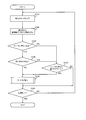
- FIG. 6 is a flowchart illustrating an operation example of the eyewear according to the present embodiment.
- FIG. 7 is a flowchart showing an example of eyewear operation when the mode of FIG. 6 is switched.
- FIG. 8A, 8B, and 8C are tables that summarize how the optical characteristics are set in accordance with the use environment.
- FIG. 9 is a table summarizing how the optical characteristics are set according to the use environment.
- FIG. 10 is a flowchart showing another operation example of the eyewear according to the present embodiment.
- FIG. 11 is a flowchart showing another operation example of the eyewear according to the present embodiment.
- FIG. 12 is a block diagram illustrating another example of the functional configuration of the eyewear according to the present embodiment.
- (Eyewear) 1 and 2 are perspective views showing an eyewear 100 according to the present embodiment.
- the eyewear has a mechanism for presenting information to so-called glasses (including electronic glasses and sunglasses) or goggles having a supplementary mechanism for improving the user's visual acuity, such as a vision correction lens, and the user's field of view or eyes.
- glasses including electronic glasses and sunglasses
- goggles having a supplementary mechanism for improving the user's visual acuity, such as a vision correction lens, and the user's field of view or eyes.
- Various devices for example, eyeglass-type wearable terminals, head-mounted displays, etc.
- electronic glasses for both eyes having a pair of lenses will be described as an example, but the eyewear according to the present invention is not limited to this aspect.
- the eyewear may be configured to hold an auxiliary mechanism for improving visual acuity or visibility and a mechanism for presenting information to the eye by being worn, and is not limited to a spectacle type that is worn on both ears. Instead, it may be a device worn only on the head or one ear. Moreover, it may be eyewear that works only on one eye, not for both eyes.
- the eyewear 100 includes a frame 110 having a front 110 and a pair of temples 120 a and 120 b, an input unit 140, and a pair of electric control types that are optical modules whose optical characteristics are changed by electric control.
- a lens 150, a control unit 160, a sensing unit 170, and a power source 180 are included.
- the control unit 160 includes, for example, an arithmetic unit 165 such as a CPU unit including a CPU (Central Processing Unit) and a RAM (Random Access Memory), and a ROM (Read Only Memory) that also functions as a storage unit, and an arithmetic unit such as a CPU unit. Including equipment.
- the CPU reads a program for executing the function of the eyewear 100 from the ROM, expands the program in the RAM, and controls the operation of each functional unit of the eyewear 100 by executing the expanded program.
- the portion where the pair of electrically controlled lenses 150 is disposed is referred to as the front (front) of the eyewear 100.
- each functional unit included in the eyewear 100 is connected by a bus B.
- the front 110 holds a pair of electrically controlled lenses 150.
- the front 110 includes a pair of rims 112 that respectively support the pair of electrically controlled lenses 150, and a bridge 114 that connects the pair of rims 112.
- the rim 112 has a shape corresponding to the shape of the electrically controlled lens 150.
- wiring for electrically connecting the electric control type lens 150 and the CPU unit 165 (control unit 160) is arranged inside the front 110.
- the material of the front 110 is not particularly limited, and may be a known material used as the front material of the glasses.
- materials for the front 110 include polyamide, acetate, carbon, celluloid, polyetherimide, and polyurethane.
- the pair of temples 120a and 120b is a rod-like member connected to the front 110 so as to be symmetric, and is connected to the front 110 at the front end thereof.
- An input unit 140, a CPU unit 165 (control unit 160), a sensing unit 170, and a power source 180 are arranged in one of the pair of temples 120a and 120b (the right temple 120a in FIGS. 1 and 2).
- the material of the temples 120a and 120b is not particularly limited, and may be a known material used as a temple material for glasses.
- Examples of materials for temples 120a and 120b include polyamide, acetate, carbon, celluloid, polyetherimide and polyurethane.
- the input unit 140 receives an input operation from a user who wears eyewear.
- the input unit 140 may be a plurality of capacitive touch sensors or the like that are arranged in a row from the front to the rear in a region outside and forward of the temple 120a.
- the pair of electrically controlled lenses 150 is a lens having an electroactive portion that is held on the front 110 of the frame and whose optical characteristics are changed by application of a voltage.
- Each electrically controlled lens may be a spherical lens or an aspheric lens.
- Each electrically controlled lens has a first region 150a in which the focal length (frequency) and visible light transmittance can be changed by applying a voltage, and a first region 150a in which the visible light transmittance can be changed by applying a voltage. 2 regions 150b.
- the electric control type lens 150 shows an example in which a transmittance variable layer 1570 (first electroactive portion) and a refractive index variable layer 1530 (second electroactive portion) are stacked. It is not limited.
- the electric control type lens 150 includes a transmittance / refractive index variable portion that changes its focal length (frequency) and visible light by applying a voltage, and a transmittance that can change the visible light transmittance by applying a voltage. It is good also as a single layer structure which combined the variable part.
- the first region 150a includes a first transparent substrate 1510, a first transparent electrode from the rear (user side). 1520, refractive index variable layer 1530 (second electroactive part), second transparent electrode 1540, second transparent substrate 1550, third transparent electrode 1560, transmittance variable layer 1570 (first electroactive part)
- the fourth transparent electrode 1580 and the third transparent substrate 1590 are laminated in this order.
- the first transparent substrate 1510 and the first transparent electrode 1520, or the second transparent substrate 1550 and the second transparent electrode 1540 have a Fresnel lens shape in the first region 150a. It may be.
- the second region 150b includes a first transparent substrate 1510, a first transparent electrode 1520, an adhesive layer 1535, a second transparent electrode 1540, a second electrode, from the rear (user side).
- the second transparent substrate 1550, the third transparent electrode 1560, the transmittance variable layer 1570 as the electroactive portion, the fourth transparent electrode 1580, and the third transparent substrate 1590 are laminated in this order.
- the second transparent electrode 1540 and the third transparent electrode 1560 may be a common electrode. At this time, the arrangement of the second transparent substrate 1550 can be omitted.
- the first transparent substrate 1510, the second transparent substrate 1550, and the third transparent substrate 1590 are transparent members that are curved so as to be convex toward the front side of the eyewear 100.
- the material of the first transparent substrate 1510, the second transparent substrate 1550, and the third transparent substrate 1590 is not particularly limited as long as it has a light-transmitting property with respect to visible light, and is a known material that can be used as a lens material. Can be a material.
- materials of the first transparent substrate 1510, the second transparent substrate 1550, and the third transparent substrate 1590 include glass and resin.
- the resin include polymethyl methacrylate, polycarbonate, polydiethylene glycol bisallyl carbonate, and polystyrene.
- the materials of the first transparent substrate 1510, the second transparent substrate 1550, and the third transparent substrate 1590 may be the same or different.
- the first transparent electrode 1520 and the second transparent electrode 1540 are a pair of transparent electrodes having translucency
- the third transparent electrode 1560 and the fourth transparent electrode 1580 are a pair of transparent electrodes having translucency. Electrode.
- the first transparent electrode 1520 and the second transparent electrode 1540 are disposed at least in a range in which a voltage can be applied to the refractive index variable layer 1530 (first region 150a), and the third transparent electrode 1560 and the fourth transparent electrode
- the electrode 1580 is disposed at least in a range where the voltage can be applied to the transmittance variable layer 1570 (the first region 150a and the second region 150b).
- the material of the first transparent electrode 1520, the second transparent electrode 1540, the third transparent electrode 1560, and the fourth transparent electrode 1580 is not particularly limited as long as it has translucency with respect to visible light and conductivity. .
- Examples of the material of the first transparent electrode 1520, the second transparent electrode 1540, the third transparent electrode 1560, and the fourth transparent electrode 1580 include indium tin oxide (ITO) and zinc oxide (ZnO).
- the materials of the first transparent electrode 1520, the second transparent electrode 1540, the third transparent electrode 1560, and the fourth transparent electrode 1580 may be the same or different.
- the refractive index variable layer 1530 is a layer that changes the refractive index of visible light by applying a voltage.
- Examples of the material of the refractive index variable layer 1530 include cholesteric liquid crystal and nematic liquid crystal.
- the transmittance variable layer 1570 is a layer that changes the transmittance of visible light by applying a voltage.
- Examples of the material of the transmittance variable layer 1570 include an electrochromic device and a guest-host liquid crystal.
- the transmittance variable layer is caused by an oxidation-reduction reaction caused by the supplied electrons or a change in the orientation of liquid crystal molecules.
- the transmittance of 1570 changes reversibly. Therefore, the transmittance variable layer 1570 changes the visible light transmittance of the first region 150a and the second region 150b by applying a voltage.
- the adhesive layer 1535 is disposed between the first transparent substrate 1510 and the second transparent substrate 1550 in the second region 150b, and bonds the first transparent substrate 1510 and the second transparent substrate 1550. .
- the adhesive layer 1535 is provided between the first transparent electrode 1520 and the second transparent electrode 1540. Placed in.
- the adhesive layer 1535 also has a function of sealing the material forming the refractive index variable layer 1530.
- the material of the adhesive layer 1535 is not particularly limited as long as it is a cured product of an adhesive having a property of transmitting visible light.
- the sensing unit 170 is a position detection sensor (for example, Global Positioning System; GPS) that can measure the position of the eyewear 100; an illuminance sensor that senses the illuminance of light; and an imaging element that identifies and senses natural light and fluorescence (for example, a camera) ); Bluetooth (“Bluetooth” is a registered trademark of Bluetooth SIG), etc., a communication module that can be connected to a predetermined mobile device such as a smartphone; proximity sensor that senses that the user is in the vicinity; contact sensor; eyewear 100 An acceleration sensor, an angular velocity sensor, or a gyro sensor that senses the movement state and posture of the wearing user, the wearing state of the eyewear 100, or the like; or a tilt sensor that senses the tilt angle of the eyewear 100 vertically downward with respect to the horizontal axis.
- GPS Global Positioning System
- GPS Global Positioning System
- illuminance sensor that senses the illuminance of light
- an imaging element that identifies and senses
- the sensing unit 170 includes information on the use environment, specifically, user position information (indoor, outdoor, home, road, etc.), light intensity and light source (natural light, fluorescent light, etc.) of the use environment, Information about the external environment, such as whether or not the device is detected (such as whether or not a given mobile device is nearby); the user's activity status (stationary, walking, exercise, movement, etc.), and the user's posture (sitting, Information on the user's state such as standing, lying on the back, etc., wearing state of the eyewear (detaching etc.), tilting of the eyewear (forward tilting, horizontal tilting, etc.) is acquired. Among them, it is preferable to acquire geographical position information and light intensity of the usage environment.
- the sensing unit 170 outputs information on the acquired use environment to the control unit 160.
- the control unit 160 can change the optical characteristics (refractive index or transmittance) of the electrically controlled lens 150 and can not change the optical characteristics. And switch. Then, the control unit 160 changes the optical characteristic of the electric control type lens 150 in the mode in which the optical characteristic of the electric control type lens 150 can be changed.
- the “changeable mode” is, for example, a state in which the control unit 160 changes the optical characteristic (refractive index or transmittance) of the electric control type lens 150 in accordance with an input from the input unit 140 or the sensing unit 170. Say something.
- the “non-changeable mode” means, for example, a state in which the sensing unit 170 or the input unit 140 cannot detect an input, or the control unit 160 performs electrical control according to an input from the input unit 140 or the sensing unit 170. This means that the optical characteristics (refractive index or transmittance) of the mold lens 150 are not changed.
- the control unit 160 changes the optical characteristics according to the external environment detected by the sensing unit 170 and the user's operation on the input unit 140.
- the function expressed by the optical characteristics can be turned on / off according to the external environment detected by the sensing unit 170 and the user's operation on the input unit 140.
- the sensing unit 170 or the input unit 140 is in an off state or a sleep state, or even if the sensing unit 170 or the input unit 140 detects an input, the control unit 160.
- the function expressed by the optical characteristics remains constant (for example, the function remains off).
- control unit 160 includes the first transparent electrode 1520, the second transparent electrode 1540, the third transparent electrode 1560, and the fourth transparent electrode 1580 of the electric control lens 150, and the input unit 140 and the sensing.
- the unit 170 is electrically connected. Based on the information acquired by the sensing unit 170, the control unit 160 determines whether to switch between a mode in which the optical characteristics of the electrically controlled lens 150 can be changed and a mode in which the optical property cannot be changed.
- the control unit 160 determines that the optical characteristics of the electrically controlled lens 150 need to be switched between a changeable mode and a non-changeable mode
- the first transparent electrode 1520 and the second transparent electrode A voltage is applied to any one of 1540, the third transparent electrode 1560, and the fourth transparent electrode 1580 to change the optical characteristics (refractive index or transmittance) of the electrically controlled lens 150 in a changeable mode and a changeless mode. Switch between possible modes.
- the control unit 160 is based on information acquired by the sensing unit 170 or to the input unit 140. The optical characteristics of the electrically controlled lens 150 are changed by receiving the input from the user.
- switching between the changeable mode and the non-changeable mode is basically performed automatically (automatic), but manually (manually) as necessary. You may make it selectable. Specifically, when the information acquired by the sensing unit 170 satisfies a predetermined condition, the control unit 160 switches between a mode in which the optical characteristics can be changed and a mode in which the optical characteristics cannot be changed (automatic mode switching). However, it is possible to select that the mode in which the optical characteristics can be changed and the mode in which the optical characteristics cannot be changed (manual mode switching) can be selected when a user's input operation is received at the input unit 140. May be.
- the selection of whether to perform the mode switching manually may be set by default, may be set by a user's input operation, or may be set by determination of the control unit 160.
- the user's input operation may be accepted only when the control unit 160 determines that mode switching is necessary, or may be accepted at an arbitrary timing unrelated thereto.
- the adjustment of the optical characteristics may be performed automatically or manually.
- the mode in which the optical characteristics can be changed includes an auto mode in which the control unit 160 changes the optical characteristics in accordance with information acquired by the sensing unit 170 (also referred to as an on-auto mode), and a user's mode. It is preferable that a manual mode (also referred to as an on-manual mode) in which optical characteristics are changed by receiving an input operation is included, and one of them can be selectively executed.
- an auto mode on / auto mode in which the optical characteristics are changed according to information acquired by the sensing unit 170.
- the selection of whether the optical characteristics are adjusted automatically or manually may be set by default, may be set by a user's input operation, or may be set by the determination of the control unit 160.
- the user's input operation may be accepted only when the control unit 160 determines that mode switching is necessary, or may be accepted at an arbitrary timing unrelated thereto.
- the types of optical characteristics changed by the control unit 160 include transmittance and refractive index.
- the controller 160 may change only one of these optical characteristics, or may change both. That is, the control unit 160 can adjust the light by changing the transmittance of the electrically controlled lens 150, the visual acuity correcting function that can perform visual acuity correction by changing the refractive index of the electrically controlled lens 150, and A hybrid function capable of changing both the transmittance and the refractive index of the electrically controlled lens 150 can be provided.
- the mode in which the optical characteristics can be changed includes the mode in which the transmittance (first optical characteristics) for changing the transmittance (first optical characteristics) of the electric control type lens 150 and the electric control type lens 150 can be changed. It is preferable to include a mode capable of changing the refractive index (second optical characteristic) for changing the refractive index (second optical characteristic). Especially, it is preferable that the control part 160 switches the mode which can change an optical characteristic, and the mode which cannot change an optical characteristic based on geographical position information and the light intensity of a use environment.
- the control unit 160 may change the optical characteristics of the electrically controlled lens 150 in two stages, on and off, or in three or more stages. It may be changed.
- the dimming function and the hybrid function have a dimming function for changing the transmittance of the electrically controlled lens 150 with respect to the illuminance of light to the eyewear 100 in multiple stages as shown in FIG. Yes.
- control unit 160 may maintain the optical characteristics of the electrically controlled lens 150 as they are, or after changing the optical characteristics to default values. This default value may be maintained.
- the power source 180 is a rechargeable battery pack that is detachably held at the rear end of the temple 120a, and supplies power to functional units that consume power, such as the input unit 140, the control unit 160, and the sensing unit 170.
- An example of the power supply 180 includes a nickel metal hydride rechargeable battery.
- FIG. 6 illustrates a case where the mode in which the optical characteristics of the electrically controlled lens 150 can be changed (function on mode) and the mode in which the optical control lens 150 cannot be changed (function off mode) are automatically switched according to the use environment in the present embodiment.
- It is a flowchart which shows the operation example of the eyewear 100.
- FIG. 7 is a flowchart showing an operation example of the eyewear 100 when the mode for the optical characteristics of the electrically controlled lens 150 is switched.
- the “mode in which the optical characteristics can be changed” is called a “function on mode” because the function expressed by the optical characteristics can be turned on as described above.
- the “mode in which the optical characteristics cannot be changed” will be referred to as a “function off mode”, taking as an example a mode in which the function remains off.
- Mode switching for dimming function Referring to FIGS. 6, 7, and 8 ⁇ / b> A, a mode (dimming) that can change the transmittance of the electrically controlled lens 150 according to the use environment (particularly the external environment).
- a mode on mode a mode in which a function on mode
- an unchangeable mode dimming function off mode
- the “dimming function on mode” is a mode in which the transmittance of the electroactive part of the electrically controlled lens 150 is changed according to the acquired geographical position information and light intensity.
- the “dimming function off mode” is a mode in which the transmittance of the electroactive portion of the electrically controlled lens 150 is not changed, for example, a mode in which the transmissivity of the electroactive portion is kept high (for example, a predetermined value of 90% or more).
- FIG. 8A is a table summarizing how the dimming function of the eyewear 100 is set according to the external environment.
- the dimming function on mode when the light intensity is higher than a predetermined value (regardless of whether the place is outdoor or indoor) or when the light intensity is lower than the predetermined value and the place is outdoors, the dimming function on mode When the light intensity is weaker than a predetermined value and the place is indoors, the dimming function off mode is set.
- the operation illustrated in FIG. 6 is started when, for example, the input unit 140, the control unit 160, and the sensing unit 170 are turned on by the attachment of the power supply 180.
- the control unit 160 determines the current mode (step S110).
- a RAM that is a storage unit included in the control unit 160 stores a currently executed mode among a plurality of modes that can be executed by the eyewear 100.
- the control unit 160 reads the currently executed mode from the ROM and determines the current mode.
- the control unit 160 acquires information on the usage environment from the sensing unit 170 and performs a predetermined determination process (step S120). Specifically, the control unit 160 compares the geographical position information of the eyewear 100 acquired from the position detection sensor (GPS) with a map database acquired in advance, so that the eyewear 100 can be placed indoors or outdoors. Determine if it exists. Further, the light intensity (such as strong or weak) of the usage environment is determined by comparing the obtained output from the light intensity sensor with a predetermined threshold (see FIG. 8A).
- the control unit 160 includes the geographical position information acquired from the position detection sensor, the information indicating whether the vehicle is indoors or outdoors, and the light intensity of the use environment acquired from the light intensity sensor.
- the information on the intensity of the light intensity determined based on the above is recorded in the RAM in association with the time when these are acquired. Then, the control unit 160 compares the information on the use environment acquired in this step and the determination result thereof with the information on the use environment acquired in the past and the determination result read from the RAM, thereby obtaining a predetermined value. The discrimination process is performed.
- the control unit 160 determines whether it is necessary to switch the mode of the dimming function based on the information acquired by the sensing unit 170 (step S130). For example, the control unit 160 determines that the usage environment of the eyewear 100 has changed from indoor to outdoor while the light intensity remains weak based on the result of step S120 (upper right column ⁇ right of FIG. 8A). (Lower column), it is determined that switching from the dimming function off mode to the dimming function on mode is necessary (determination 1). Although the light intensity is weak, since the place is outdoors, turning on the dimming function can reduce the light transmittance and protect the user's eyes from sudden sunlight.
- control unit 160 determines based on the result of step S120 that the usage environment of eyewear 100 has changed from a low light intensity state to a strong state and the location has changed from outdoor to indoor. (Lower right column ⁇ upper left column in FIG. 8A), the dimming function on mode is maintained without switching to the dimming function off mode (determination 2). Although it is indoors, since the light intensity is strong, the user's eyes can be protected by continuously turning on the dimming function.
- step S130 it is determined that the change in the environment is determined by comparing the information on the usage environment acquired in the past acquired in step S120 with the usage environment currently acquired.
- the present invention is not limited to this. .
- the mode switching may be determined based on the information on the currently used usage environment according to the table shown in FIG. 8A without using the information on the usage environment acquired in the past.
- step S130 when the control unit 160 determines that the mode of the dimming function needs to be switched, the control unit 160 further determines whether the information acquired by the sensing unit 170 does not satisfy the exclusion condition (step S140).
- Exclusion conditions include, for example, driving, moving stairs, and the like. Based on the information acquired by the sensing unit 170, the control unit 160 checks whether or not an exclusion condition is met.
- step S140 when the control unit 160 determines that the exclusion condition is not satisfied, the control unit 160 switches the mode of the dimming function (step S150). For example, when the control unit 160 makes the above-described determination 1 in step S130, the control unit 160 switches the dimming function mode from OFF to ON (upper right column ⁇ lower right column in FIG. 8A). The operation (step S150) for switching the dimming function mode will be described later.
- control unit 160 determines in step S130 that it is not necessary to switch the mode of the dimming function, or when the control unit 160 determines in step S140 that the information acquired by the sensing unit 170 satisfies the exclusion condition.
- the control unit 160 further determines whether or not a mode switching input operation from the user has been received (step S170).
- step S170 when the control unit 160 determines that an input operation from the user to the input unit 140 has been received, the control unit 160 switches the mode of the dimming function (step S150).
- the input unit 140 is a touch sensor, and switches the dimming function mode based on a touch operation by the user.
- the control unit 160 determines that the input operation from the user has not been received, the process transitions to step S160.
- step S130 when the control unit 160 makes the above-described determination 2 in step S130, the control unit 160 does not switch the dimming function mode unless the user's instruction is accepted, and the process proceeds to step S160. Transition to maintain the dimming function on mode (lower right column ⁇ upper left column in FIG. 8A).
- step S150 after switching the mode of the dimming function, the switched mode of the dimming function is recorded in the ROM, and the control unit 160 determines whether the process is completed (step S160).
- the control unit 160 determines that the process needs to be terminated when a predetermined condition for terminating the process is satisfied. On the other hand, when the above condition is not satisfied, it is determined that it is not necessary to end the process. As a result of the determination, if it is necessary to end the process, the process in FIG. 6 ends. On the other hand, if it is not necessary to end the process, the process returns to before step S110.
- step S150 the operation when switching the mode of the light control function
- step S151 the control unit 160 switches the mode of the dimming function.
- step S152 the control unit 160 determines whether or not the mode after switching is the dimming function on mode.
- the “dimming function on mode” there are two types of modes in the “dimming function on mode”.
- One is a mode “dimming function on / auto mode” in which the transmittance (parameter adjustment) of the electroactive portion of the electrically controlled lens 150 is automatically adjusted regardless of the user's input operation;
- This is a “dimming function on / manual mode” in which the transmittance of the electroactive portion of the electrically controlled lens 150 is adjusted according to an input operation.
- step S152 when the control unit 160 determines that the mode after switching is the dimming function on mode, the control unit 160 adjusts the transmittance of the electroactive portion of the electrically controlled lens 150 (parameter adjustment). It is further determined whether or not it is a mode for performing the auto (“light control function on / auto mode”) (step S153).
- step S153 when the control unit 160 determines that the “dimming function on / auto mode” is set, the control unit 160 determines that the information acquired by the sensing unit 170 satisfies a predetermined condition.
- the transmittance of 150 is adjusted (step S154).
- step S153 when the control unit 160 determines that the mode is not the mode for automatically adjusting the transmittance (the dimming function is on / manual mode), the control unit 160 instructs the user to input from the input unit 140. Accordingly, the transmittance of the electrically controlled lens 150 is adjusted (step S155).
- step S152 when the control unit 160 determines that the mode after switching is the dimming function off mode, the control unit 160 changes the transmittance of the electrically controlled lens 150 to a default value (step S156). Then, the process returns to step S150 in FIG.
- step S152 the control unit 160 determines whether the switched mode is the dimming function on mode.
- step S153 the control unit 160 determines whether or not to automatically adjust the transmittance (in the “dimming function on / auto mode”). If the control unit 160 determines that the transmittance is to be automatically adjusted (“light control function on / auto mode”), the transmission is performed based on the information acquired by the sensing unit 170. For example, the transmittance is set to 50%. Thereafter, the transmittance can be changed according to the information of the sensing unit 170.
- step S153 when it is determined in step S153 that the control unit 160 is not in a mode in which the transmittance is adjusted automatically (the light control function is on / manual mode), the transmittance is calculated based on an input instruction from the user. For example, the transmittance is 50%. Thereafter, the transmittance can be changed in accordance with an input instruction from the user to the input unit 140.
- step S152 if control unit 160 determines that the mode after switching is the dimming function off mode, in step S156, for example, control unit 160 has a high transmittance (for example, a value close to 100%). Change to default value to make transparent eyewear. Thereafter, as long as the mode is not changed, the control unit 160 does not change the transmittance.
- a high transmittance for example, a value close to 100%. Change to default value to make transparent eyewear. Thereafter, as long as the mode is not changed, the control unit 160 does not change the transmittance.
- the refractive index of the electrically controlled lens 150 can be changed and cannot be changed according to the use environment (particularly the external environment).
- An example of automatically switching between different modes (automatically switching the vision correction function mode) will be described.
- the “vision correction function on mode” is a mode in which the refractive index of the electroactive part of the electrically controlled lens 150 is changed according to the acquired geographical position information and light intensity.
- the “vision correction function off mode” refers to a mode in which the refractive index of the electroactive portion of the electrically controlled lens 150 is not changed.
- FIG. 8B is a table summarizing how the mode related to the eyesight correction function of the eyewear is set according to the external environment.
- the vision correction function on mode is set and whether the light intensity is stronger or weaker than the predetermined value. Regardless of the location) Set the vision correction function off mode when the place is outdoors.
- Steps S110 and S120 are the same as described above.
- step S ⁇ b> 130 the control unit 160 determines whether it is necessary to switch the mode of the vision correction function based on the information acquired by the sensing unit 170. For example, when the control unit 160 determines that the usage environment of the eyewear 100 has changed from outdoor to indoor based on the result of step S120 (lower column to upper column in FIG. 8B), the vision correction function off mode It is determined that it is necessary to switch from the eyesight correction function to the on mode (determination 3). Since the place is indoors, it is possible to adjust the refractive index by turning on the visual acuity correction function and enhance the visibility in the indoors.
- control unit 160 determines that the usage environment of eyewear 100 has changed from a strong light intensity state to a weak light state, and that the place is indoors (FIG. 8B). (Upper left column ⁇ upper right column), the eyesight correction function on mode is maintained without switching to the eyesight correction function off mode (determination 4). Since it is indoors, the visual field of the user can be secured by continuously turning on the vision correction function.
- step S130 when the control unit 160 determines that the mode of the vision correction function needs to be switched, the control unit 160 further determines whether the information acquired by the sensing unit 170 does not satisfy the exclusion condition, as described above.
- the control unit 160 determines that the exclusion condition is not met (step S140)
- the control unit 160 switches the mode of the vision correction function (step S150). For example, when the control unit 160 makes the above-described determination 3 in step S130, the control unit 160 switches the mode of the visual acuity correction function from off to on (lower column ⁇ upper column in FIG. 8B). Thereafter, the process transitions to step S160.
- step S130 determines in step S130 that it is not necessary to switch the mode of the vision correction function, or when the control unit 160 determines in step S140 that the information acquired by the sensing unit 170 corresponds to the exclusion condition.
- the process transitions to step S170.
- the control unit 160 makes the above-described determination 4 in step S130, the control unit 160 does not switch the mode of the visual acuity correction function and maintains the visual acuity correction function on mode (upper left column in FIG. 8B ⁇ Upper right column).
- Steps S160 and S170 are the same as described above.
- step S150 the operation for switching the mode of the visual acuity correction function can be performed in the same manner as described above.
- the control unit 160 determines whether or not the mode after switching is the vision correction function on mode.
- the mode after switching is the vision correction function on mode.
- One is a mode that automatically adjusts the refractive index (parameter adjustment) of the electroactive portion of the electrically controlled lens 150 regardless of the user's input operation.
- This is a “visual acuity correction function on manual mode” in which the refractive index of the electroactive part of the electrically controlled lens 150 is adjusted according to an input operation.
- step S153 the control unit 160 determines whether or not to automatically adjust the refractive index (in the “visual acuity correction function on / auto mode”). If the control unit 160 determines that the eyesight correction function is on / auto mode, the refractive index is changed based on the information acquired by the sensing unit 170. Thereafter, the refractive index can be changed based on the information acquired by the sensing unit 170.
- step S153 when the control unit 160 determines that the “eyesight correction function on / auto mode” is not set (the eyesight correction function on / manual mode), the refractive index is calculated based on the user's input instruction. Change. Thereafter, the refractive index can be changed in accordance with an input instruction from the user to the input unit 140.
- step S152 when the control unit 160 determines that the mode after switching is the visual acuity correction function off mode, in step S156, the control unit 160 changes the refractive index to, for example, a default value. Thereafter, the control unit 160 does not change the refractive index.
- the “dimming function on mode” and the “dimming function off mode” have the same meanings as the “dimming function on mode” and “dimming function off mode” described in (1) above, “Vision correction function on mode” and “sight correction function off mode” are respectively synonymous with “sight correction function on mode” and “sight correction function off mode” of the electric control type lens 150 of (2) described above. .
- FIG. 8C is a table summarizing how the dimming function and the eyesight correction function of the eyewear 100 are set according to the external environment.
- the dimming function on mode is set.
- the light control function off mode is set.
- the vision correction function on mode (regardless of whether the light intensity is stronger or weaker than the predetermined value)
- the vision correction function off mode when the camera is outdoors, set the vision correction function off mode.
- Steps S110 and S120 are the same as described above.
- step S130 based on the information acquired by the sensing unit 170, the control unit 160 determines whether it is necessary to switch modes for each of the dimming function and the vision correction function.
- control unit 160 determines that the usage environment of eyewear 100 has changed from outdoor to indoor while the light intensity remains weak (lower right column in FIG. 8C ⁇ In the upper right column), it is determined that switching from the dimming function on mode to the dimming function off mode and switching from the vision correction function off mode to the vision correction function on mode are necessary (determination 5). Since the place is indoors, it is possible to secure the user's indoor visual field by turning off the dimming function and turning on the vision correction function.
- the control unit 160 determines that the usage environment of the eyewear 100 has changed from a weak state to a strong state and the location has changed from outdoor to indoor ( In FIG. 8C, lower right column ⁇ upper left column), the dimming function off mode is maintained without switching to the dimming function off mode; and switching from the vision correction function off mode to the vision correction function on mode is necessary. (Judgment 6). Although the place is indoor, since the light intensity is strong, it is possible to secure the user's indoor visual field by keeping the dimming function on and turning on the vision correction function.
- step S130 when the control unit 160 determines that the mode switching is necessary for each of the dimming function and the vision correction function, the control unit 160 further determines whether the information acquired by the sensing unit 170 does not satisfy the exclusion condition. Judgment is made (step S140). When the control unit 160 determines that the exclusion condition is not satisfied, the control unit 160 switches between the dimming function mode and the vision correction function mode (step S150). For example, when the control unit 160 makes the above-described determination 5 in step S130, the dimming function mode is switched from on to off, and the vision correction function mode is switched from off to on (lower right column in FIG. 8C ⁇ Upper right column). Thereafter, the process transitions to step S160.
- control unit 160 determines that it is not necessary to switch the mode for each of the dimming function and the vision correction function in step S130, or the information acquired by the sensing unit 170 in step S140 is the exclusion condition.
- the process proceeds to step S170.
- step S170 for the dimming function mode
- step S160 unless a mode switching instruction is received from the user. Transition.
- the control part 160 complete finishes a process in step S160, or returns before step S110, and maintains the light control function ON mode (lower right column-> upper left column of FIG. 8C).
- the mode of the visual acuity correction function is switched from off to on as described above (lower right column ⁇ upper left column in FIG. 8C). Thereafter, the process transitions to step S160.
- Steps S160 and S170 are the same as described above.
- step S150 when switching between the dimming function mode and the vision correction function mode is the same as described above.
- step S152 the control unit 160 determines whether the mode after switching between the dimming function and the vision correction function is the function on mode, respectively. Judge whether. If the control unit 160 determines that the mode after switching between the dimming function and the vision correction function is the function-on mode, whether or not the control unit 160 automatically adjusts the transmittance and the refractive index in step S153. If the control unit 160 determines that the transmission and the refractive index are automatically adjusted (the function on / auto mode), the detection is performed. Based on the information acquired by the unit 170, the transmittance and the refractive index are changed. Thereafter, the transmittance and the refractive index can be changed according to the information of the sensing unit 170.
- step S153 when the control unit 160 determines that the mode is not a mode in which the transmittance and the refractive index are automatically adjusted (function on / manual mode), an input instruction from the user to the input unit 140 Based on the above, the transmittance and the refractive index are changed. Thereafter, the transmittance and the refractive index can be changed in accordance with an input instruction from the user to the input unit 140.
- step S152 when the control unit 160 determines that the mode after switching between the light control function and the vision correction function is the function off mode, in step S156, the control unit 160 sets the transmittance and the refractive index to the default values. To change each. Thereafter, the control unit 160 does not change the transmittance and the refractive index.
- FIG. 9 is a table summarizing how the dimming function and the eyesight correction function of the eyewear 100 are set according to the external environment and the user's activity state.
- the dimming function on mode is set, and in other cases (the user's activity even if the place is indoors) Set the dimming function off mode when the user is walking or when the location is outdoors, and the user ’s activity status is walking or when the location is outdoors. If there is, set the vision correction function off mode.
- Step S110 is the same as described above.
- step S120 the control unit 160 acquires information on the usage environment from the sensing unit 170, and performs predetermined determination processing. Specifically, by comparing the geographical position information (such as indoor or outdoor) of the eyewear 100 acquired by the position detection sensor (GPS) with a map database acquired in advance, Determine if you are outdoors. Further, the user's activity status (stationary, walking, driving) is determined by comparing the output from the acquired acceleration sensor and position detection sensor (GPS) with a predetermined threshold.
- the control unit 160 includes the geographical position information acquired from the position detection sensor, the information indicating whether the vehicle is indoors or outdoors, and the user activity acquired from the acceleration sensor and the position detection sensor. Information about the situation is recorded in the RAM in association with the time when these were acquired. Then, the control unit 160 compares the information on the use environment acquired in this step and the determination result thereof with the information on the use environment acquired in the past and the determination result read from the RAM, thereby obtaining a predetermined value. The discrimination process is performed.
- step S130 based on the information acquired by the sensing unit 170, the control unit 160 determines whether it is necessary to switch modes for each of the light control function and the vision correction function. For example, based on the result of step S120, the control unit 160 determines that the usage environment of the eyewear 100 has changed from a walking state to a stationary state, and the location has changed from outdoor to indoor. Is determined (lower center column ⁇ upper left column in FIG. 9), it is determined that switching from the dimming function on mode to the dimming function off mode and switching from the vision correction function off mode to the vision correction function on mode are necessary. (Judgment 7).
- the control unit 160 determines that the usage environment of the eyewear 100 changes from a walking state to a driving state and that the place is outdoors ( In FIG. 9, the lower center column ⁇ the lower right column), the dimming function off mode and the vision correction function on mode are not switched, and the dimming function on mode and the vision correction function off mode are continued (determination). 8). Since it is outdoors, the user's eyes can be protected by continuously turning on the dimming function.
- step S130 it is determined that the change in the environment is determined by comparing the information on the usage environment acquired in the past acquired in step S120 with the usage environment currently acquired.
- the present invention is not limited to this. .
- the mode switching may be determined based on the information on the currently used usage environment according to the table shown in FIG. 9 without using the information on the usage environment acquired in the past.
- step S130 when the control unit 160 determines that it is necessary to switch modes for each of the dimming function and the vision correction function, the control unit 160 applies the information acquired by the sensing unit 170 to the exclusion condition as described above. It is further determined whether or not to do so (step S140). And when the control part 160 judges that it does not correspond to exclusion conditions, the control part 160 switches each mode of a light control function and a visual acuity correction function (step S150). For example, when the control unit 160 makes the above-described determination 7 in step S130, the control unit 160 switches the dimming function mode from on to off, and switches the vision correction function mode from off to on ( The lower center column in FIG. 9 ⁇ the upper left column). Thereafter, the process transitions to step S160.
- step S130 determines that it is not necessary to switch the mode for each of the dimming function and the vision correction function in step S130, or the information acquired by the sensing unit 170 in step S140 is the exclusion condition.
- the process proceeds to step S170.
- the control unit 160 makes the above-described determination 8 in step S130, the control unit 160 does not switch the mode for each of the dimming function and the vision correction function, and maintains the dimming function on mode.
- the visual acuity correction function off mode is maintained (lower center column ⁇ lower right column in FIG. 9). Thereafter, the process transitions to step S160.
- Steps S150, S160 and S170 are the same as described above.
- the control unit 160 switches the mode when it is determined that the mode switching is necessary based on the information on the usage environment, thereby reducing the user's input operation.
- control unit 160 automatically switches the mode when the control unit 160 determines that the mode needs to be switched in step S130. However, the control unit 160 switches the mode automatically. It may be possible to select whether the mode is switched or the mode is switched manually by accepting an input operation by the user.
- FIG. 10 shows that, in the present embodiment, when the control unit 160 determines that the mode needs to be switched, it is possible to select whether the mode is switched automatically or whether the mode is switched manually by accepting an input operation by the user.
- 5 is a flowchart illustrating an operation example of the eyewear 100.
- FIG. 10 is the same as FIG. 6 except that steps S180, S190, and S200 are further included between step S140 and step S150.
- step S140 when the control unit 160 determines that the exclusion condition is not satisfied, the control unit 160 further determines whether or not the mode is switched automatically (step S180). Specifically, when a predetermined condition for switching the mode automatically is satisfied, the mode is set to “light control function on / auto mode” in order to switch the mode automatically (step S150).
- step S190 the control unit 160 presents the “switch destination mode name” and “user interface (UI) for selecting whether or not to switch” to the user.
- the presentation of these “switch destination mode name” and “user interface (UI) for selecting whether to switch” is, for example, a smartphone that has received information transmitted via the communication unit 192 of the eyewear 100 This can be done via the display (see FIG. 12).
- control part 160 judges whether there exists consent of the mode switching by a user (step S200).
- the mode is switched (step S150).
- the process proceeds to step S160.
- the control unit 160 determines that the mode needs to be switched, the mode is not always switched automatically but the mode is switched by accepting a user's input operation. Therefore, it is possible to switch the mode appropriately to meet the needs of the user.
- step S180 the example in which the control unit 160 performs the selection of whether the mode is switched automatically or manually is shown. It may be performed by acceptance or default setting.
- FIG. 11 is a flowchart illustrating an operation example of the eyewear 100 when the mode of the other optical characteristic is switched based on the mode switching result of the one optical characteristic according to the use environment in the present embodiment. .
- FIG. 11 is the same as FIG. 6 except that steps S210 and S220 are further included between steps S150 and S160.
- step S150 when the control unit 160 switches the mode for one of the two optical characteristics, the control unit 160 interlocks with the mode switching result of the one optical characteristic for the other optical characteristic. It is further determined whether it is necessary to switch the mode (step S210). Specifically, when the result of switching the mode of one optical characteristic satisfies a predetermined condition, it is determined that it is necessary to switch the mode of the other optical characteristic.
- step S210 When it is determined in step S210 that the mode for the other optical characteristic needs to be switched, the control unit 160 switches the mode for the other optical characteristic (step S220). On the other hand, when it is determined in step S210 that it is not necessary to switch the mode for the other optical characteristic, the process proceeds to step S160.
- step S210 the control unit 160 acquires information on the use environment and the current mode of the dimming function, It is determined whether to switch the mode for the dimming function.
- the control unit 160 may switch the dimming function to the function off mode.
- the control unit 160 may switch the dimming function to the function on mode.
- the transmittance of the electrically controlled lens 150 is determined to be indoors, for example, when the eyewear is indoors, because it is better to see the hand better than when it is outdoors.
- the transmittance is adjusted to be higher than in the “dimming function on mode” in the case where the outdoor mode is determined.
- the “light adjustment function on mode” is set when the visual acuity correction function is on, it is preferable to adjust so that the transmittance is higher than when the visual acuity correction function is off.
- step S150 when the vision correction function mode is switched from the function on mode to the function off mode, in step S210, the control unit 160 determines whether to switch the mode for the dimming function.
- the control unit 160 switches the dimming function to the function off mode and shifts to the sleep mode or turns off the power.
- the dimming function is also switched off as a trigger when the mode of the visual acuity correction function is switched off.
- step S150 when it is detected that the eyewear is not moved for a predetermined time based on the output of the acceleration sensor or the like after the mode of the visual acuity correction function is switched from on to off, the dimming function is performed. It is also possible to switch to the function off mode and shift to the sleep mode or turn off the power.
- step S150 when the dimming function mode is switched from off to on, in step S210, the control unit 160 determines whether to switch the mode for the vision correction function. For example, when the current mode of the visual acuity correction function is the function on mode, in step S220, when it is determined that the eyewear is outdoors, the control unit 160 switches the visual acuity correction function to the function off mode. Triggered by the switching of the dimming function mode, an unnecessary vision correction function can be turned off to save power.
- step S150 when the dimming function mode is switched from on to off, the control unit 160 determines whether to switch the mode for the vision correction function.
- the control unit 160 may switch the vision correction function to the function on mode.
- the current mode of the visual acuity correction function is the function on mode
- step S220 for example, when the control unit 160 detects that the eyewear is not moved for a predetermined time based on the output of the acceleration sensor or the like.
- the vision correction function may also be switched to the function off mode to shift to the sleep mode, or the power may be turned off.
- the control unit 160 switches the mode for one optical characteristic
- the mode switching for the other optical characteristic is performed in conjunction with the switching result of the mode. Therefore, it is possible to switch the mode appropriately for the use environment while reducing the operation burden on the user.
- control unit 160 changes the changeable mode for the other optical characteristic based on the result of switching between the changeable mode and the non-changeable mode for one optical characteristic.
- the present invention is not limited to this, but is not limited to this.
- a mode in which the other optical characteristic can be changed automatically (a mode in which parameter adjustment is performed automatically) and the other optical characteristic are changed.
- a mode that can be changed manually (a mode in which parameter adjustment is performed manually) may be switched.
- the control unit 160 sets the dimming function mode to “ON so that the transmittance can be changed manually. Mode "(dimming function on / manual mode) may be switched.
- step S150 when the mode of the vision correction function is switched from on to off, in step S220, the current mode of the dimming function is “on mode in which the transmittance can be changed automatically” (the dimming function on). If the user is outdoors, the control unit 160 may change the mode of the dimming function by changing the mode of the dimming function manually. It may be switched to “Available On Mode” (dimming function on / manual mode).
- step S150 when the dimming function mode is switched from off to on, in step S220, the current mode of the visual acuity correction function is “an on mode in which the refractive index can be changed automatically” (the visual acuity correction function on).
- the control unit 160 sets the mode of the vision correction function to “ON which can change the refractive index manually because the user is outdoors and it is desired that the vision correction can be manually adjusted. It may be switched to “mode” (sight correction function on / manual mode).
- step S170 which receives input operation was shown, it is not limited to this, You may abbreviate
- step S140 whether or not the information acquired by the sensing unit 170 corresponds to the exclusion condition when the control unit 160 determines that the mode switching is necessary in step S130.
- the present invention is not limited to this and step S140 may be omitted.
- control unit 160 changes the optical characteristics when switching the mode (when switching to a mode in which the optical characteristics can be changed) has been described in step S130. Even when the mode is not switched, the optical characteristics may be changed based on the information acquired by the sensing unit 170 whenever the current mode is a mode in which the optical characteristics can be changed.
- control unit 160 performs the adjustment of the optical characteristics in two steps (on / off) when the mode after switching is the function on mode in step S150 has been described.
- the present invention is not limited to this.
- the adjustment may be performed in multiple stages as shown in FIG.
- step S150 when the function-on mode of the first optical characteristic is selected, there is one pattern (adjustment degree) when changing the first optical characteristic.
- the function on mode (preferably the function on / auto mode) of the first optical characteristic may include a plurality of modes having different patterns when changing the first optical characteristic of the optical module.
- the control unit 160 may switch to one of the plurality of modes based on the information acquired by the sensing unit 170.
- the dimming function on mode may include a plurality of modes (indoor mode: light color dimming function on mode, outdoor mode: dark color dimming function on mode, etc.) having different patterns for changing the transmittance.
- step S153 for selecting whether to change the optical characteristics automatically or manually.
- step S153 may be omitted.
- the control unit 160 may automatically change the optical characteristics based on the information acquired by the sensing unit 170. .
- none of the steps includes a step of storing the condition (information regarding the use environment) when the control unit 160 determines that the mode switching is necessary in step S130 and the mode after the switching in association with each other.
- the condition (information on the use environment) when the control unit 160 determines that the mode needs to be switched is associated with the contents of the mode after the switching and is recorded in the storage unit Steps may be further executed (see FIG. 12 described later).
- the present invention is not limited to this, and other functional configurations can be adopted.
- FIG. 12 is a block diagram showing another example of the functional configuration of eyewear.
- the eyewear 100 is switched with conditions (information on usage environment) when the mode is switched after the communication unit 192 and the control unit 160 that can communicate with other devices switch the mode.
- a storage unit 194 that stores the types of later modes in association with each other, and an output unit 196 that can be wired or wirelessly connected to an external notification device that notifies a display device such as a display or a function change such as an LED lamp. And so on.
- Each functional unit included in the eyewear is connected by a bus B.
- the storage unit 194 associates the condition (information on the use environment) when the mode is switched after the control unit 160 switches the mode and the mode type after the switching. You may add and memorize it. Then, when the mode is switched by the auto function, the control unit 160 may read the determination condition stored in the storage unit and determine whether to perform the mode switching based on the read condition.
- the example in which the electrically controlled lens 150 has two electroactive portions is shown, but the present invention is not limited to this. You may have and may have three or more electroactive parts.
- control unit 160 changes the optical characteristic by one or two types is shown, but the present invention is not limited to this, and there may be three or more types.
- an electric control type lens has been described as an example of an optical module whose optical characteristics change by electric control.
- the present invention is not limited to this, and the projection unit 198 and a projection target (for example, transparent) It may be an optical module or the like that can project images and videos.
- the eyewear of the present invention can be switched between modes for changing optical characteristics according to the usage environment. Therefore, the eyewear of the present invention is expected to contribute to the spread and advancement of eyewear in this field.
Abstract
Eyewear having: a frame; an optical module held by the frame and changing optical properties by electric control; a sensing unit that obtains information pertaining to a usage environment; and a control unit that, on the basis of the information obtained by the sensing unit, changes the optical properties of the optical module. The control unit switches between a mode in which optical properties of can be changed and a mode in which optical properties cannot be changed, on the basis of the information obtained by the sensing unit, and changes the optical properties of the optical module when in the mode in which optical properties can be changed. As a result, eyewear is provided that can switch between modes that change or do not change optical properties, in accordance with the usage environment.
Description
本発明は、アイウェアに関する。
The present invention relates to eyewear.
近年、使用者が装着可能な電子機器(ウェアラブルデバイス)の開発が行われている。
In recent years, electronic devices (wearable devices) that can be worn by users have been developed.
たとえば、特許文献1には、眼鏡本体の傾斜角度によって液晶レンズへの電気信号を制御して、焦点距離を自動的に可変にするアイウェア(眼鏡)が記載されている。
For example, Patent Document 1 describes eyewear (glasses) that automatically changes the focal length by controlling an electrical signal to the liquid crystal lens according to the inclination angle of the eyeglass body.
また、特許文献2には、使用者の視距離、視線または頭の傾きなどを検出して、レンズの焦点距離などを変化させるアイウェアが記載されている。
Patent Document 2 describes eyewear that detects a user's viewing distance, line of sight, or head tilt, and changes the focal length of the lens.
さらに、特許文献3には、光強度センサで使用環境下での光強度を検出し、それに基づいてエレクトロクロミック素子を制御して透過率を変化させ、さらに映像表示部の光源の光強度を調整するサングラスが記載されている。
Furthermore, in Patent Document 3, the light intensity sensor detects the light intensity in the use environment, and based on this, the electrochromic element is controlled to change the transmittance, and further the light intensity of the light source of the image display unit is adjusted. Sunglasses to be described.
特許文献1や2に記載されるようなアイウェアは、一旦、視力補正機能がオンの状態になると、常にその状態が維持される。同様に、特許文献3に記載されるようなサングラスは、一旦、調光機能がオンの状態になると、常にその状態が維持される。
The eyewear described in Patent Documents 1 and 2 is always maintained once the visual acuity correction function is turned on. Similarly, sunglasses as described in Patent Document 3 are always maintained once the dimming function is turned on.
しかしながら、アイウェアの使用環境(シチュエーション)によっては、視力補正機能や調光機能が常に維持されると、不都合が生じる場合もある。例えば、常に調光機能が維持された状態で、屋外から屋内に移動すると、屋内では調光機能が強すぎて視界が遮られやすいなどの問題がある。つまり、特許文献3に記載されるようなサングラスは、光強度センサで検出された結果に基づいて透過率を調整することはできても、使用環境に応じて調光機能自体のオン・オフを自動で切り替えることはできない。したがって、使用環境に応じて、たとえば調光機能のオン・オフなどの、光学特性を変化させるかどうかのモードの切り替えが可能なアイウェアが望まれる。
However, depending on the usage environment (situation) of the eyewear, inconvenience may occur if the vision correction function and the dimming function are always maintained. For example, if the dimming function is always maintained and the vehicle moves from the outdoors to the indoors, there is a problem that the dimming function is too strong and the field of view is easily blocked. That is, the sunglasses as described in Patent Document 3 can adjust the transmittance based on the result detected by the light intensity sensor, but turn on / off the dimming function itself according to the use environment. It cannot be switched automatically. Therefore, eyewear capable of switching modes for changing optical characteristics, such as on / off of the dimming function, is desired depending on the use environment.
上記問題に鑑み、本発明は、使用環境に応じて、光学特性を変化させるかどうかのモードの切り替えが可能なアイウェアを提供することを目的とする。
In view of the above problems, an object of the present invention is to provide eyewear capable of switching modes depending on the usage environment, whether to change optical characteristics.
本発明の一態様は、フレームと、フレームに配置され、電気制御により光学特性が変化する光学モジュールと、使用環境に関する情報を取得する感知部と、感知部で取得した情報に基づいて、光学モジュールの光学特性を変化させる制御部とを有し、制御部は、感知部で取得した情報に基づいて、光学特性を変化可能なモードと、光学特性を変化不可能なモードとを切り替え、かつ光学特性を変化可能なモードのときに、光学モジュールの光学特性を変化させる、アイウェアに関する。
One embodiment of the present invention includes a frame, an optical module that is arranged in the frame and whose optical characteristics are changed by electrical control, a sensing unit that acquires information about a use environment, and an optical module based on information acquired by the sensing unit A control unit that changes the optical characteristics of the sensor, and the control unit switches between a mode in which the optical characteristics can be changed and a mode in which the optical characteristics cannot be changed based on information acquired by the sensing unit, and the optical The present invention relates to eyewear that changes optical characteristics of an optical module in a mode in which characteristics can be changed.
本発明によれば、使用環境に応じて、光学特性を変化させるかどうかのモードの切り替えが可能なアイウェアが提供される。
According to the present invention, there is provided eyewear capable of switching modes depending on the usage environment, whether to change the optical characteristics.
以下、本実施形態に係るアイウェアについて説明する。
Hereinafter, the eyewear according to the present embodiment will be described.
(アイウェア)
図1および図2は、本実施形態に係るアイウェア100を示す斜視図である。アイウェアは、例えば、視力補正レンズのようにユーザの視力向上のための補助機構を有するいわゆる眼鏡(電子メガネ、サングラスを含む)やゴーグル、ユーザの視界あるいは眼に対して情報提示を行う機構を有する種々のデバイス(例えば、眼鏡型ウェアラブル端末、ヘッドマウントディスプレイ等)が含まれる。以下の本実施形態では、一対のレンズを有する両目用の電子眼鏡を例に説明するが、本発明に係るアイウェアは、この態様に限定されない。アイウェアは、装着されることにより、眼に対して視力または視界向上のための補助機構や情報提示のための機構を保持する構成であればよく、両方の耳に装着される眼鏡型に限らず、頭部や片方の耳のみに装着される装置であってもよい。また、両眼用ではなく、片眼のみに作用するアイウェアであってもよい。 (Eyewear)
1 and 2 are perspective views showing aneyewear 100 according to the present embodiment. The eyewear has a mechanism for presenting information to so-called glasses (including electronic glasses and sunglasses) or goggles having a supplementary mechanism for improving the user's visual acuity, such as a vision correction lens, and the user's field of view or eyes. Various devices (for example, eyeglass-type wearable terminals, head-mounted displays, etc.) are included. In the following embodiment, electronic glasses for both eyes having a pair of lenses will be described as an example, but the eyewear according to the present invention is not limited to this aspect. The eyewear may be configured to hold an auxiliary mechanism for improving visual acuity or visibility and a mechanism for presenting information to the eye by being worn, and is not limited to a spectacle type that is worn on both ears. Instead, it may be a device worn only on the head or one ear. Moreover, it may be eyewear that works only on one eye, not for both eyes.
図1および図2は、本実施形態に係るアイウェア100を示す斜視図である。アイウェアは、例えば、視力補正レンズのようにユーザの視力向上のための補助機構を有するいわゆる眼鏡(電子メガネ、サングラスを含む)やゴーグル、ユーザの視界あるいは眼に対して情報提示を行う機構を有する種々のデバイス(例えば、眼鏡型ウェアラブル端末、ヘッドマウントディスプレイ等)が含まれる。以下の本実施形態では、一対のレンズを有する両目用の電子眼鏡を例に説明するが、本発明に係るアイウェアは、この態様に限定されない。アイウェアは、装着されることにより、眼に対して視力または視界向上のための補助機構や情報提示のための機構を保持する構成であればよく、両方の耳に装着される眼鏡型に限らず、頭部や片方の耳のみに装着される装置であってもよい。また、両眼用ではなく、片眼のみに作用するアイウェアであってもよい。 (Eyewear)
1 and 2 are perspective views showing an
図1および図2に示すように、アイウェア100は、フロント110および一対のテンプル120aおよび120bを有するフレーム130、入力部140、電気制御により光学特性が変化する光学モジュールである一対の電気制御型レンズ150、制御部160、感知部170、ならびに電源180を有する。制御部160は、例えばCPU(Central Processing Unit)およびRAM(Random Access Memory)、ならびに記憶部としても機能するROM(Read Only Memory)などが含まれるCPUユニットなどの演算装置165やCPUユニットなどの演算装置を含む。CPUは、アイウェア100の機能を実行するためのプログラムをROMから読み出してRAMに展開し、展開したプログラムを実行してアイウェア100の各機能部の動作を制御する。なお、以下の記載では、一対の電気制御型レンズ150が配置されている部分をアイウェア100の正面(前方)とする。
As shown in FIGS. 1 and 2, the eyewear 100 includes a frame 110 having a front 110 and a pair of temples 120 a and 120 b, an input unit 140, and a pair of electric control types that are optical modules whose optical characteristics are changed by electric control. A lens 150, a control unit 160, a sensing unit 170, and a power source 180 are included. The control unit 160 includes, for example, an arithmetic unit 165 such as a CPU unit including a CPU (Central Processing Unit) and a RAM (Random Access Memory), and a ROM (Read Only Memory) that also functions as a storage unit, and an arithmetic unit such as a CPU unit. Including equipment. The CPU reads a program for executing the function of the eyewear 100 from the ROM, expands the program in the RAM, and controls the operation of each functional unit of the eyewear 100 by executing the expanded program. In the following description, the portion where the pair of electrically controlled lenses 150 is disposed is referred to as the front (front) of the eyewear 100.
また、アイウェア100の機能構成を表すブロック図である図3に示すように、アイウェア100が備える各機能部は、バスBにより接続される。
Further, as shown in FIG. 3, which is a block diagram showing a functional configuration of the eyewear 100, each functional unit included in the eyewear 100 is connected by a bus B.
フロント110は、一対の電気制御型レンズ150を保持する。フロント110は、上記一対の電気制御型レンズ150をそれぞれ支持する一対のリム112と、上記一対のリム112を接続するブリッジ114と、を有する。リム112は、電気制御型レンズ150の形状に対応する形状を有する。特に図示しないが、フロント110の内部には、電気制御型レンズ150とCPUユニット165(制御部160)とを電気的に接続するための配線が配置されている。
The front 110 holds a pair of electrically controlled lenses 150. The front 110 includes a pair of rims 112 that respectively support the pair of electrically controlled lenses 150, and a bridge 114 that connects the pair of rims 112. The rim 112 has a shape corresponding to the shape of the electrically controlled lens 150. Although not particularly illustrated, wiring for electrically connecting the electric control type lens 150 and the CPU unit 165 (control unit 160) is arranged inside the front 110.
フロント110の材料は、特に限定されず、メガネのフロントの材料として使用されている公知の材料とすることができる。フロント110の材料の例には、ポリアミド、アセテート、カーボン、セルロイド、ポリエーテルイミドおよびポリウレタンが含まれる。
The material of the front 110 is not particularly limited, and may be a known material used as the front material of the glasses. Examples of materials for the front 110 include polyamide, acetate, carbon, celluloid, polyetherimide, and polyurethane.
一対のテンプル120aおよび120bは、左右対称となるようにフロント110に接続された棒状の部材であり、その前端部においてフロント110に接続される。一対のテンプル120aおよび120bの一方(図1および図2では右側のテンプル120a)には、入力部140、CPUユニット165(制御部160)、感知部170および電源180が配置される。
The pair of temples 120a and 120b is a rod-like member connected to the front 110 so as to be symmetric, and is connected to the front 110 at the front end thereof. An input unit 140, a CPU unit 165 (control unit 160), a sensing unit 170, and a power source 180 are arranged in one of the pair of temples 120a and 120b (the right temple 120a in FIGS. 1 and 2).
テンプル120aおよび120bの材料は、特に限定されず、メガネのテンプルの材料として使用されている公知の材料とすることができる。テンプル120aおよび120bの材料の例には、ポリアミド、アセテート、カーボン、セルロイド、ポリエーテルイミドおよびポリウレタンが含まれる。
The material of the temples 120a and 120b is not particularly limited, and may be a known material used as a temple material for glasses. Examples of materials for temples 120a and 120b include polyamide, acetate, carbon, celluloid, polyetherimide and polyurethane.
入力部140は、アイウェアを装着する使用者などからの入力動作を受け付ける。入力部140は、テンプル120aの外側かつ前方の領域に、前方から後方に向けて列状に配置された複数の静電容量型のタッチセンサなどでありうる。
The input unit 140 receives an input operation from a user who wears eyewear. The input unit 140 may be a plurality of capacitive touch sensors or the like that are arranged in a row from the front to the rear in a region outside and forward of the temple 120a.
一対の電気制御型レンズ150は、フレームのフロント110に保持された、電圧の印加により光学特性が変化する電気活性部を有するレンズである。それぞれの電気制御型レンズは、球面レンズであってもよいし、非球面レンズであってもよい。それぞれの電気制御型レンズは、電圧の印加によりその焦点距離(度数)および可視光の透過率を変更可能な第1の領域150aと、電圧の印加によりその可視光の透過率を変更可能な第2の領域150bとを有する。
The pair of electrically controlled lenses 150 is a lens having an electroactive portion that is held on the front 110 of the frame and whose optical characteristics are changed by application of a voltage. Each electrically controlled lens may be a spherical lens or an aspheric lens. Each electrically controlled lens has a first region 150a in which the focal length (frequency) and visible light transmittance can be changed by applying a voltage, and a first region 150a in which the visible light transmittance can be changed by applying a voltage. 2 regions 150b.
なお、以下において、電気制御型レンズ150は、透過率可変層1570(第1の電気活性部)と屈折率可変層1530(第2の電気活性部)とを積層する例を示すが、これに限定されない。たとえば、電気制御型レンズ150を、電圧の印加によりその焦点距離(度数)および可視光が変化する透過率・屈折率可変部と、電圧の印加によりその可視光の透過率を変更可能な透過率可変部とを組み合わせた単層構成としてもよい。
In the following, the electric control type lens 150 shows an example in which a transmittance variable layer 1570 (first electroactive portion) and a refractive index variable layer 1530 (second electroactive portion) are stacked. It is not limited. For example, the electric control type lens 150 includes a transmittance / refractive index variable portion that changes its focal length (frequency) and visible light by applying a voltage, and a transmittance that can change the visible light transmittance by applying a voltage. It is good also as a single layer structure which combined the variable part.
電気制御型レンズ150のA-A部分の模式断面図である図4に示すように、第1の領域150aは、後方(使用者側)から、第1の透明基板1510、第1の透明電極1520、屈折率可変層1530(第2の電気活性部)、第2の透明電極1540、第2の透明基板1550、第3の透明電極1560、透過率可変層1570(第1の電気活性部)、第4の透明電極1580、および第3の透明基板1590がこの順に積層されてなる。
As shown in FIG. 4 which is a schematic cross-sectional view of the AA portion of the electrically controlled lens 150, the first region 150a includes a first transparent substrate 1510, a first transparent electrode from the rear (user side). 1520, refractive index variable layer 1530 (second electroactive part), second transparent electrode 1540, second transparent substrate 1550, third transparent electrode 1560, transmittance variable layer 1570 (first electroactive part) The fourth transparent electrode 1580 and the third transparent substrate 1590 are laminated in this order.
なお、特に図示はしないが、第1の透明基板1510および第1の透明電極1520、または第2の透明基板1550および第2の透明電極1540は、第1の領域150aにおいてフレネルレンズ形状を有していてもよい。
Although not particularly illustrated, the first transparent substrate 1510 and the first transparent electrode 1520, or the second transparent substrate 1550 and the second transparent electrode 1540 have a Fresnel lens shape in the first region 150a. It may be.
また、図4に示すように、第2の領域150bは、後方(使用者側)から、第1の透明基板1510、第1の透明電極1520、接着層1535、第2の透明電極1540、第2の透明基板1550、第3の透明電極1560、電気活性部としての透過率可変層1570、第4の透明電極1580、および第3の透明基板1590がこの順に積層されてなる。
Further, as shown in FIG. 4, the second region 150b includes a first transparent substrate 1510, a first transparent electrode 1520, an adhesive layer 1535, a second transparent electrode 1540, a second electrode, from the rear (user side). The second transparent substrate 1550, the third transparent electrode 1560, the transmittance variable layer 1570 as the electroactive portion, the fourth transparent electrode 1580, and the third transparent substrate 1590 are laminated in this order.
なお、第2の透明電極1540と第3の透明電極1560とは、共通電極としてもよい。このとき、第2の透明基板1550は、その配置を省略することができる。
Note that the second transparent electrode 1540 and the third transparent electrode 1560 may be a common electrode. At this time, the arrangement of the second transparent substrate 1550 can be omitted.
第1の透明基板1510、第2の透明基板1550および第3の透明基板1590は、アイウェア100の前方側に向かって凸状となるように湾曲した透明部材である。
The first transparent substrate 1510, the second transparent substrate 1550, and the third transparent substrate 1590 are transparent members that are curved so as to be convex toward the front side of the eyewear 100.
第1の透明基板1510、第2の透明基板1550および第3の透明基板1590の材料は、可視光に対する透光性を有していれば特に限定されず、レンズの材料として使用されうる公知の材料とすることができる。第1の透明基板1510、第2の透明基板1550および第3の透明基板1590の材料の例には、ガラスおよび樹脂が含まれる。上記樹脂の例には、ポリメチルメタクリレート、ポリカーボネート、ポリジエチレングリコールビスアリルカーボネートおよびポリスチレンが含まれる。第1の透明基板1510、第2の透明基板1550および第3の透明基板1590の材料は、同一であってもよいし、異なっていてもよい。
The material of the first transparent substrate 1510, the second transparent substrate 1550, and the third transparent substrate 1590 is not particularly limited as long as it has a light-transmitting property with respect to visible light, and is a known material that can be used as a lens material. Can be a material. Examples of materials of the first transparent substrate 1510, the second transparent substrate 1550, and the third transparent substrate 1590 include glass and resin. Examples of the resin include polymethyl methacrylate, polycarbonate, polydiethylene glycol bisallyl carbonate, and polystyrene. The materials of the first transparent substrate 1510, the second transparent substrate 1550, and the third transparent substrate 1590 may be the same or different.
第1の透明電極1520および第2の透明電極1540は、透光性を有する一対の透明電極であり、第3の透明電極1560および第4の透明電極1580は、透光性を有する一対の透明電極である。
The first transparent electrode 1520 and the second transparent electrode 1540 are a pair of transparent electrodes having translucency, and the third transparent electrode 1560 and the fourth transparent electrode 1580 are a pair of transparent electrodes having translucency. Electrode.
第1の透明電極1520および第2の透明電極1540は、少なくとも屈折率可変層1530に電圧を印加しうる範囲(第1の領域150a)に配置され、第3の透明電極1560および第4の透明電極1580は、少なくとも透過率可変層1570に電圧を印加しうる範囲(第1の領域150aおよび第2の領域150b)に配置される。
The first transparent electrode 1520 and the second transparent electrode 1540 are disposed at least in a range in which a voltage can be applied to the refractive index variable layer 1530 (first region 150a), and the third transparent electrode 1560 and the fourth transparent electrode The electrode 1580 is disposed at least in a range where the voltage can be applied to the transmittance variable layer 1570 (the first region 150a and the second region 150b).
第1の透明電極1520、第2の透明電極1540、第3の透明電極1560および第4の透明電極1580の材料は、可視光に対する透光性と導電性とを有するものであれば特に限定されない。第1の透明電極1520、第2の透明電極1540、第3の透明電極1560および第4の透明電極1580の材料の例には、酸化インジウムスズ(ITO)および酸化亜鉛(ZnO)が含まれる。第1の透明電極1520、第2の透明電極1540、第3の透明電極1560および第4の透明電極1580の材料は、同一であってもよいし、異なっていてもよい。
The material of the first transparent electrode 1520, the second transparent electrode 1540, the third transparent electrode 1560, and the fourth transparent electrode 1580 is not particularly limited as long as it has translucency with respect to visible light and conductivity. . Examples of the material of the first transparent electrode 1520, the second transparent electrode 1540, the third transparent electrode 1560, and the fourth transparent electrode 1580 include indium tin oxide (ITO) and zinc oxide (ZnO). The materials of the first transparent electrode 1520, the second transparent electrode 1540, the third transparent electrode 1560, and the fourth transparent electrode 1580 may be the same or different.
屈折率可変層1530は、電圧の印加により可視光の屈折率を変化させる層である。屈折率可変層1530の材料の例には、コレステリック液晶およびネマティック液晶などが含まれる。第1の透明電極1520および第2の透明電極1540によって屈折率可変層1530に電圧が印加されると、液晶分子の配向が変化することなどにより、屈折率可変層1530の屈折率が可逆的に変化する。そのため、屈折率可変層1530は、電圧の印加により、第1の領域150aの焦点距離(度数)を変化させる。
The refractive index variable layer 1530 is a layer that changes the refractive index of visible light by applying a voltage. Examples of the material of the refractive index variable layer 1530 include cholesteric liquid crystal and nematic liquid crystal. When a voltage is applied to the refractive index variable layer 1530 by the first transparent electrode 1520 and the second transparent electrode 1540, the refractive index of the refractive index variable layer 1530 is reversibly changed due to a change in the orientation of liquid crystal molecules. Change. Therefore, the refractive index variable layer 1530 changes the focal length (frequency) of the first region 150a by applying a voltage.
透過率可変層1570は、電圧の印加によって可視光の透過率を変化させる層である。透過率可変層1570の材料の例には、エレクトロクロミック素子およびゲスト-ホスト液晶などが含まれる。第3の透明電極1560および第4の透明電極1580によって透過率可変層1570に電圧が印加されると、供給された電子による酸化還元反応や、液晶分子の配向の変化などにより、透過率可変層1570の透過率が可逆的に変化する。そのため、透過率可変層1570は、電圧の印加により、第1の領域150aおよび第2の領域150bの可視光の透過率を変化させる。
The transmittance variable layer 1570 is a layer that changes the transmittance of visible light by applying a voltage. Examples of the material of the transmittance variable layer 1570 include an electrochromic device and a guest-host liquid crystal. When a voltage is applied to the transmittance variable layer 1570 by the third transparent electrode 1560 and the fourth transparent electrode 1580, the transmittance variable layer is caused by an oxidation-reduction reaction caused by the supplied electrons or a change in the orientation of liquid crystal molecules. The transmittance of 1570 changes reversibly. Therefore, the transmittance variable layer 1570 changes the visible light transmittance of the first region 150a and the second region 150b by applying a voltage.
接着層1535は、第2の領域150bにおいて、第1の透明基板1510と第2の透明基板1550との間に配置されて、第1の透明基板1510と第2の透明基板1550とを接着する。第1の透明電極1520および第2の透明電極1540が、第2の領域150bにも配置される場合には、接着層1535は、第1の透明電極1520と第2の透明電極1540との間に配置される。また、接着層1535は、屈折率可変層1530を構成する材料を封止する機能も有する。接着層1535の材料は、可視光に対する透光性を有する、接着剤の硬化物であれば特に限定されない。
The adhesive layer 1535 is disposed between the first transparent substrate 1510 and the second transparent substrate 1550 in the second region 150b, and bonds the first transparent substrate 1510 and the second transparent substrate 1550. . In the case where the first transparent electrode 1520 and the second transparent electrode 1540 are also disposed in the second region 150b, the adhesive layer 1535 is provided between the first transparent electrode 1520 and the second transparent electrode 1540. Placed in. The adhesive layer 1535 also has a function of sealing the material forming the refractive index variable layer 1530. The material of the adhesive layer 1535 is not particularly limited as long as it is a cured product of an adhesive having a property of transmitting visible light.
感知部170は、アイウェア100の位置を測定可能な位置検出センサ(例えばGlobal Positioning System;GPS);光の照度を感知する照度センサ;自然光と蛍光とを識別して感知する撮像素子(例えばカメラ);Bluetooth(「Bluetooth」はBluetooth SIGの登録商標)などでスマートフォンなどの所定のモバイル機器と接続可能な通信モジュール;使用者が近傍にいることを感知する近接センサ;接触センサ;アイウェア100を装着した使用者の移動状態や姿勢、アイウェア100の装着状態などを感知する加速度センサ、角速度センサまたはジャイロセンサ;あるいは、水平軸に対する鉛直下方へのアイウェア100の傾斜角度を感知する傾斜センサなどを有する。
The sensing unit 170 is a position detection sensor (for example, Global Positioning System; GPS) that can measure the position of the eyewear 100; an illuminance sensor that senses the illuminance of light; and an imaging element that identifies and senses natural light and fluorescence (for example, a camera) ); Bluetooth (“Bluetooth” is a registered trademark of Bluetooth SIG), etc., a communication module that can be connected to a predetermined mobile device such as a smartphone; proximity sensor that senses that the user is in the vicinity; contact sensor; eyewear 100 An acceleration sensor, an angular velocity sensor, or a gyro sensor that senses the movement state and posture of the wearing user, the wearing state of the eyewear 100, or the like; or a tilt sensor that senses the tilt angle of the eyewear 100 vertically downward with respect to the horizontal axis. Have
そして、感知部170は、使用環境に関する情報、具体的には、使用者の位置情報(屋内、屋外、自宅、道路など)、使用環境の光強度や光源(自然光、蛍光灯など)、他の装置の検出の有無(所定のモバイル機器が近傍にあるかどうかなど)などの外的環境に関する情報や;使用者の活動状態(静止、歩行、運動、移動など)、使用者の姿勢(着座、起立、仰向けなど)、アイウェアの装着状態(着脱など)、アイウェアの傾き(前傾、水平、後傾など)などの使用者の状態に関する情報を取得する。中でも、地理的な位置情報および使用環境の光強度を取得することが好ましい。
Then, the sensing unit 170 includes information on the use environment, specifically, user position information (indoor, outdoor, home, road, etc.), light intensity and light source (natural light, fluorescent light, etc.) of the use environment, Information about the external environment, such as whether or not the device is detected (such as whether or not a given mobile device is nearby); the user's activity status (stationary, walking, exercise, movement, etc.), and the user's posture (sitting, Information on the user's state such as standing, lying on the back, etc., wearing state of the eyewear (detaching etc.), tilting of the eyewear (forward tilting, horizontal tilting, etc.) is acquired. Among them, it is preferable to acquire geographical position information and light intensity of the usage environment.
感知部170は、取得した使用環境に関する情報を、制御部160に出力する。
The sensing unit 170 outputs information on the acquired use environment to the control unit 160.
制御部160は、感知部170または入力部140で取得した情報に基づいて、電気制御型レンズ150の光学特性(屈折率又は透過率)を変化可能なモードと、光学特性を変化不可能なモードとを切り替える。そして、制御部160は、電気制御型レンズ150の光学特性を変化可能なモードのときに、電気制御型レンズ150の光学特性を変化させる。
Based on information acquired by the sensing unit 170 or the input unit 140, the control unit 160 can change the optical characteristics (refractive index or transmittance) of the electrically controlled lens 150 and can not change the optical characteristics. And switch. Then, the control unit 160 changes the optical characteristic of the electric control type lens 150 in the mode in which the optical characteristic of the electric control type lens 150 can be changed.
「変化可能なモード」とは、例えば、制御部160が、入力部140や感知部170からの入力に応じて、電気制御型レンズ150の光学特性(屈折率又は透過率)を変化させる状態にあることをいう。また、「変化不可能なモード」とは、例えば、感知部170または入力部140が入力を検出できない状態、あるいは、制御部160が入力部140や感知部170からの入力に応じて、電気制御型レンズ150の光学特性(屈折率又は透過率)を変化させない状態にあることをいう。
「変化可能なモード」においては、制御部160は、感知部170により検出された外部環境や、入力部140に対するユーザの操作に応じて、光学特性を変化させる。つまり、「変化可能なモード」においては、感知部170により検出された外部環境や、入力部140に対するユーザの操作に応じて、光学特性により発現する機能がオン・オフされる、ということもできる。
一方で、「変化不可能なモード」においては、感知部170または入力部140はオフ状態やスリープ状態であるか、あるいは、感知部170または入力部140が入力を検出したとしても、制御部160は光学特性の変化をさせることは無い。つまり、「変化不可能なモード」においては、光学特性により発現する機能が一定のまま変化しない(例えば、機能がオフ状態のまま)ことになる。 The “changeable mode” is, for example, a state in which thecontrol unit 160 changes the optical characteristic (refractive index or transmittance) of the electric control type lens 150 in accordance with an input from the input unit 140 or the sensing unit 170. Say something. In addition, the “non-changeable mode” means, for example, a state in which the sensing unit 170 or the input unit 140 cannot detect an input, or the control unit 160 performs electrical control according to an input from the input unit 140 or the sensing unit 170. This means that the optical characteristics (refractive index or transmittance) of the mold lens 150 are not changed.
In the “changeable mode”, thecontrol unit 160 changes the optical characteristics according to the external environment detected by the sensing unit 170 and the user's operation on the input unit 140. That is, in the “changeable mode”, the function expressed by the optical characteristics can be turned on / off according to the external environment detected by the sensing unit 170 and the user's operation on the input unit 140. .
On the other hand, in the “non-changeable mode”, thesensing unit 170 or the input unit 140 is in an off state or a sleep state, or even if the sensing unit 170 or the input unit 140 detects an input, the control unit 160. Does not change the optical properties. That is, in the “non-changeable mode”, the function expressed by the optical characteristics remains constant (for example, the function remains off).
「変化可能なモード」においては、制御部160は、感知部170により検出された外部環境や、入力部140に対するユーザの操作に応じて、光学特性を変化させる。つまり、「変化可能なモード」においては、感知部170により検出された外部環境や、入力部140に対するユーザの操作に応じて、光学特性により発現する機能がオン・オフされる、ということもできる。
一方で、「変化不可能なモード」においては、感知部170または入力部140はオフ状態やスリープ状態であるか、あるいは、感知部170または入力部140が入力を検出したとしても、制御部160は光学特性の変化をさせることは無い。つまり、「変化不可能なモード」においては、光学特性により発現する機能が一定のまま変化しない(例えば、機能がオフ状態のまま)ことになる。 The “changeable mode” is, for example, a state in which the
In the “changeable mode”, the
On the other hand, in the “non-changeable mode”, the
具体的には、制御部160は、電気制御型レンズ150の第1の透明電極1520、第2の透明電極1540、第3の透明電極1560および第4の透明電極1580、ならびに入力部140および感知部170に電気的に接続されている。制御部160は、感知部170が取得した情報に基づいて、電気制御型レンズ150の光学特性を変化可能なモードと変化不可能なモードとを切り替えるかどうかを判断する。そして、制御部160が、電気制御型レンズ150の光学特性について、変化可能なモードと変化不可能なモードとの切り替えが必要と判断したときに、第1の透明電極1520、第2の透明電極1540、第3の透明電極1560および第4の透明電極1580のいずれかに電圧を印加して、電気制御型レンズ150の光学特性(屈折率または透過率)についての、変化可能なモードと変化不可能なモードとを切り替える。そして、電気制御型レンズ150の光学特性(屈折率または透過率)を変化可能なモードを選択したときに、制御部160は、感知部170で取得した情報に基づいて、または入力部140への使用者の入力受け付けにより、電気制御型レンズ150の光学特性を変化させる。
Specifically, the control unit 160 includes the first transparent electrode 1520, the second transparent electrode 1540, the third transparent electrode 1560, and the fourth transparent electrode 1580 of the electric control lens 150, and the input unit 140 and the sensing. The unit 170 is electrically connected. Based on the information acquired by the sensing unit 170, the control unit 160 determines whether to switch between a mode in which the optical characteristics of the electrically controlled lens 150 can be changed and a mode in which the optical property cannot be changed. When the control unit 160 determines that the optical characteristics of the electrically controlled lens 150 need to be switched between a changeable mode and a non-changeable mode, the first transparent electrode 1520 and the second transparent electrode A voltage is applied to any one of 1540, the third transparent electrode 1560, and the fourth transparent electrode 1580 to change the optical characteristics (refractive index or transmittance) of the electrically controlled lens 150 in a changeable mode and a changeless mode. Switch between possible modes. Then, when a mode capable of changing the optical characteristics (refractive index or transmittance) of the electrically controlled lens 150 is selected, the control unit 160 is based on information acquired by the sensing unit 170 or to the input unit 140. The optical characteristics of the electrically controlled lens 150 are changed by receiving the input from the user.
電気制御型レンズ150の光学特性についての、変化可能なモードと変化不可能なモードとの切り替えは、基本的にはオート(自動)で行うが、必要に応じてマニュアル(手動)で行うことを選択できるようにしてもよい。具体的には、制御部160は、感知部170で取得した情報が所定の条件を満たしたときに、光学特性を変化可能なモードと変化不可能なモードとを切り替えること(オートでのモード切り替え)が好ましいが、入力部140で使用者の入力操作を受け付けたときに、光学特性を変化可能なモードと変化不可能なモードとを切り替えられること(マニュアルでのモード切り替え)を選択できるようにしてもよい。
Regarding the optical characteristics of the electrically controlled lens 150, switching between the changeable mode and the non-changeable mode is basically performed automatically (automatic), but manually (manually) as necessary. You may make it selectable. Specifically, when the information acquired by the sensing unit 170 satisfies a predetermined condition, the control unit 160 switches between a mode in which the optical characteristics can be changed and a mode in which the optical characteristics cannot be changed (automatic mode switching). However, it is possible to select that the mode in which the optical characteristics can be changed and the mode in which the optical characteristics cannot be changed (manual mode switching) can be selected when a user's input operation is received at the input unit 140. May be.
マニュアルでのモード切り替えを行うかどうかの選択は、デフォルト設定されてもよいし、使用者の入力操作により設定されてもよいし、制御部160の判断により設定されてもよい。使用者の入力操作は、制御部160がモードの切り替えが必要と判断したときのみ受け付けてもよいし、それとは無関係の任意のタイミングで受け付けてもよい。
The selection of whether to perform the mode switching manually may be set by default, may be set by a user's input operation, or may be set by determination of the control unit 160. The user's input operation may be accepted only when the control unit 160 determines that mode switching is necessary, or may be accepted at an arbitrary timing unrelated thereto.
制御部160が、光学特性を変化可能なモードを選択したとき、光学特性(パラメータ)の調整は、オートで行ってもよいし、マニュアルで行ってもよい。具体的には、光学特性が変化可能なモードには、制御部160が、感知部170で取得した情報に応じて光学特性を変化させるオートモード(オン・オートモードともいう)と、使用者の入力操作の受け付けによって光学特性を変化させるマニュアルモード(オン・マニュアルモードともいう)とが含まれ、いずれか一方を選択的に実行できるようになっていることが好ましい。中でも、制御部160が、光学特性を変化可能なモードを選択したとき、感知部170で取得した情報に応じて、光学特性を変化させるオートモード(オン・オートモード)を実行することが好ましい。
When the control unit 160 selects a mode in which the optical characteristics can be changed, the adjustment of the optical characteristics (parameters) may be performed automatically or manually. Specifically, the mode in which the optical characteristics can be changed includes an auto mode in which the control unit 160 changes the optical characteristics in accordance with information acquired by the sensing unit 170 (also referred to as an on-auto mode), and a user's mode. It is preferable that a manual mode (also referred to as an on-manual mode) in which optical characteristics are changed by receiving an input operation is included, and one of them can be selectively executed. In particular, when the control unit 160 selects a mode in which the optical characteristics can be changed, it is preferable to execute an auto mode (on / auto mode) in which the optical characteristics are changed according to information acquired by the sensing unit 170.
光学特性の調整をオートで行うかマニュアルで行うかの選択は、デフォルト設定されてもよいし、使用者の入力操作により設定されてもよいし、制御部160の判断により設定されてもよい。使用者の入力操作は、制御部160がモードの切り替えが必要と判断したときのみ受け付けてもよいし、それとは無関係の任意のタイミングで受け付けてもよい。
The selection of whether the optical characteristics are adjusted automatically or manually may be set by default, may be set by a user's input operation, or may be set by the determination of the control unit 160. The user's input operation may be accepted only when the control unit 160 determines that mode switching is necessary, or may be accepted at an arbitrary timing unrelated thereto.
本実施形態において、制御部160が変化させる光学特性の種類には、透過率および屈折率が含まれる。制御部160は、これらの光学特性のうち一方のみを変化させてもよいし、両方を変化させてもよい。つまり、制御部160は、電気制御型レンズ150の透過率を変化させて調光を行いうる調光機能、電気制御型レンズ150の屈折率を変化させて視力補正を行いうる視力補正機能、ならびに電気制御型レンズ150の透過率および屈折率の両方を変化させうるハイブリッド機能を有しうる。
In the present embodiment, the types of optical characteristics changed by the control unit 160 include transmittance and refractive index. The controller 160 may change only one of these optical characteristics, or may change both. That is, the control unit 160 can adjust the light by changing the transmittance of the electrically controlled lens 150, the visual acuity correcting function that can perform visual acuity correction by changing the refractive index of the electrically controlled lens 150, and A hybrid function capable of changing both the transmittance and the refractive index of the electrically controlled lens 150 can be provided.
中でも、光学特性を変化可能なモードは、電気制御型レンズ150の透過率(第1の光学特性)を変化させる透過率(第1の光学特性)を変化可能なモードと、電気制御型レンズ150の屈折率(第2の光学特性)を変化させる屈折率(第2の光学特性)を変化可能なモードとを含むことが好ましい。中でも、制御部160は、地理的な位置情報および使用環境の光強度に基づいて、光学特性を変化可能なモードと、光学特性を変化不可能なモードとを切り替えることが好ましい。
Among them, the mode in which the optical characteristics can be changed includes the mode in which the transmittance (first optical characteristics) for changing the transmittance (first optical characteristics) of the electric control type lens 150 and the electric control type lens 150 can be changed. It is preferable to include a mode capable of changing the refractive index (second optical characteristic) for changing the refractive index (second optical characteristic). Especially, it is preferable that the control part 160 switches the mode which can change an optical characteristic, and the mode which cannot change an optical characteristic based on geographical position information and the light intensity of a use environment.
制御部160が光学特性を変化可能なモードを選択したとき、制御部160は、電気制御型レンズ150の光学特性をオン・オフの2段階で変化させてもよいし、3段階以上の段階で変化させてもよい。たとえば、本実施形態において、調光機能およびハイブリッド機能は、アイウェア100への光の照度に対する電気制御型レンズ150の透過率を、図5に示すように多段階に変化させる調光機能を有しうる。
When the control unit 160 selects a mode in which the optical characteristics can be changed, the control unit 160 may change the optical characteristics of the electrically controlled lens 150 in two stages, on and off, or in three or more stages. It may be changed. For example, in the present embodiment, the dimming function and the hybrid function have a dimming function for changing the transmittance of the electrically controlled lens 150 with respect to the illuminance of light to the eyewear 100 in multiple stages as shown in FIG. Yes.
制御部160が光学特性を変化不可能なモードを選択したとき、制御部160は、電気制御型レンズ150の光学特性をそのまま維持してもよいし、光学特性をデフォルト値に変化させた上で、このデフォルト値を維持するようにしてもよい。
When the control unit 160 selects a mode in which the optical characteristics cannot be changed, the control unit 160 may maintain the optical characteristics of the electrically controlled lens 150 as they are, or after changing the optical characteristics to default values. This default value may be maintained.
電源180は、テンプル120aの後端部に着脱可能に保持される充電式のバッテリーパックであり、入力部140、制御部160および感知部170などの電力を消費する機能部に電力を供給する。電源180の例には、ニッケル水素充電池が含まれる。
The power source 180 is a rechargeable battery pack that is detachably held at the rear end of the temple 120a, and supplies power to functional units that consume power, such as the input unit 140, the control unit 160, and the sensing unit 170. An example of the power supply 180 includes a nickel metal hydride rechargeable battery.
(アイウェアの使用例)
図6は、本実施形態において、使用環境に応じて、電気制御型レンズ150の光学特性について変化可能なモード(機能オンモード)と変化不可能なモード(機能オフモード)とをオートで切り替えるときの、アイウェア100の動作例を示すフローチャートである。図7は、電気制御型レンズ150の光学特性についてのモードを切り替えるときの、アイウェア100の動作例を示すフローチャートである。
なお、本実施形態において、「光学特性を変化可能なモード」は、上述した通り、光学特性により発現される機能がオン可能な状態にあるため、「機能オンモード」と呼ぶ。「光学特性を変化不可能なモード」は、ここでは機能がオフされた状態のままであるモードを例として、「機能オフモード」と呼ぶことにする。 (Example of eyewear usage)
FIG. 6 illustrates a case where the mode in which the optical characteristics of the electrically controlledlens 150 can be changed (function on mode) and the mode in which the optical control lens 150 cannot be changed (function off mode) are automatically switched according to the use environment in the present embodiment. It is a flowchart which shows the operation example of the eyewear 100. FIG. 7 is a flowchart showing an operation example of the eyewear 100 when the mode for the optical characteristics of the electrically controlled lens 150 is switched.
In the present embodiment, the “mode in which the optical characteristics can be changed” is called a “function on mode” because the function expressed by the optical characteristics can be turned on as described above. The “mode in which the optical characteristics cannot be changed” will be referred to as a “function off mode”, taking as an example a mode in which the function remains off.
図6は、本実施形態において、使用環境に応じて、電気制御型レンズ150の光学特性について変化可能なモード(機能オンモード)と変化不可能なモード(機能オフモード)とをオートで切り替えるときの、アイウェア100の動作例を示すフローチャートである。図7は、電気制御型レンズ150の光学特性についてのモードを切り替えるときの、アイウェア100の動作例を示すフローチャートである。
なお、本実施形態において、「光学特性を変化可能なモード」は、上述した通り、光学特性により発現される機能がオン可能な状態にあるため、「機能オンモード」と呼ぶ。「光学特性を変化不可能なモード」は、ここでは機能がオフされた状態のままであるモードを例として、「機能オフモード」と呼ぶことにする。 (Example of eyewear usage)
FIG. 6 illustrates a case where the mode in which the optical characteristics of the electrically controlled
In the present embodiment, the “mode in which the optical characteristics can be changed” is called a “function on mode” because the function expressed by the optical characteristics can be turned on as described above. The “mode in which the optical characteristics cannot be changed” will be referred to as a “function off mode”, taking as an example a mode in which the function remains off.
(1)調光機能に関するモードの切り替え
図6、7および図8Aを参照しながら、使用環境(特に外的環境)に応じて、電気制御型レンズ150の透過率について変化可能なモード(調光機能オンモード)と変化不可能なモード(調光機能オフモード)とをオートで切り替える(調光機能のモードをオートで切り替える)例について説明する。
本実施形態において、「調光機能オンモード」とは、取得された地理的な位置情報及び光強度に応じて、電気制御型レンズ150の電気活性部の透過率を変化させるモードであり、「調光機能オフモード」とは、電気制御型レンズ150の電気活性部の透過率を変化させないモード、例えば電気活性部の透過率を高い状態(例えば90%以上の所定値)のまま変化させないモードをいう。 (1) Mode switching for dimming function Referring to FIGS. 6, 7, and 8 </ b> A, a mode (dimming) that can change the transmittance of the electrically controlledlens 150 according to the use environment (particularly the external environment). A description will be given of an example in which a function on mode) and an unchangeable mode (dimming function off mode) are switched automatically (the mode of the dimming function is switched automatically).
In the present embodiment, the “dimming function on mode” is a mode in which the transmittance of the electroactive part of the electrically controlledlens 150 is changed according to the acquired geographical position information and light intensity. The “dimming function off mode” is a mode in which the transmittance of the electroactive portion of the electrically controlled lens 150 is not changed, for example, a mode in which the transmissivity of the electroactive portion is kept high (for example, a predetermined value of 90% or more). Say.
図6、7および図8Aを参照しながら、使用環境(特に外的環境)に応じて、電気制御型レンズ150の透過率について変化可能なモード(調光機能オンモード)と変化不可能なモード(調光機能オフモード)とをオートで切り替える(調光機能のモードをオートで切り替える)例について説明する。
本実施形態において、「調光機能オンモード」とは、取得された地理的な位置情報及び光強度に応じて、電気制御型レンズ150の電気活性部の透過率を変化させるモードであり、「調光機能オフモード」とは、電気制御型レンズ150の電気活性部の透過率を変化させないモード、例えば電気活性部の透過率を高い状態(例えば90%以上の所定値)のまま変化させないモードをいう。 (1) Mode switching for dimming function Referring to FIGS. 6, 7, and 8 </ b> A, a mode (dimming) that can change the transmittance of the electrically controlled
In the present embodiment, the “dimming function on mode” is a mode in which the transmittance of the electroactive part of the electrically controlled
図8Aは、外的環境に応じて、アイウェア100の調光機能をどのように設定するかをまとめた表である。図8Aでは、たとえば、光強度が所定値よりも強いとき(場所が屋外か屋内に関係なく)や、光強度が所定値よりも弱くても場所が屋外であるときは、調光機能オンモードに設定し、光強度が所定値よりも弱く、かつ場所が屋内であるときは、調光機能オフモードに設定する。
図6に示す動作は、たとえば、電源180の取り付けによって入力部140、制御部160および感知部170がオン状態になることにより開始される。 FIG. 8A is a table summarizing how the dimming function of theeyewear 100 is set according to the external environment. In FIG. 8A, for example, when the light intensity is higher than a predetermined value (regardless of whether the place is outdoor or indoor) or when the light intensity is lower than the predetermined value and the place is outdoors, the dimming function on mode When the light intensity is weaker than a predetermined value and the place is indoors, the dimming function off mode is set.
The operation illustrated in FIG. 6 is started when, for example, theinput unit 140, the control unit 160, and the sensing unit 170 are turned on by the attachment of the power supply 180.
図6に示す動作は、たとえば、電源180の取り付けによって入力部140、制御部160および感知部170がオン状態になることにより開始される。 FIG. 8A is a table summarizing how the dimming function of the
The operation illustrated in FIG. 6 is started when, for example, the
まず、制御部160は、現在のモードを判別する(ステップS110)。たとえば、制御部160に含まれる記憶部であるRAMには、アイウェア100が実行可能な複数のモードのうち、現在実行しているモードが記憶されている。制御部160は、ROMから現在実行しているモードを読み出して、現在のモードを判別する。
First, the control unit 160 determines the current mode (step S110). For example, a RAM that is a storage unit included in the control unit 160 stores a currently executed mode among a plurality of modes that can be executed by the eyewear 100. The control unit 160 reads the currently executed mode from the ROM and determines the current mode.
次いで、制御部160は、感知部170から使用環境に関する情報を取得し、所定の判別処理を行う(ステップS120)。具体的には、制御部160は、位置検出センサ(GPS)より取得したアイウェア100の地理的な位置情報を、事前に取得した地図データベースと照合することにより、アイウェア100が屋内あるいは屋外にあるかを判別する。また、取得した光強度センサからの出力を所定の閾値と比較することにより、使用環境の光強度(強いか弱いかなど)を判別する(図8A参照)。
ここで、制御部160は、位置検出センサから取得した地理的な位置情報及びこれに基づいて判別された屋内あるいは屋外にあるかを示す情報、光強度センサから取得した使用環境の光強度及びこれに基づいて判別された光強度の強弱に関する情報を、これらが取得された時間と関連付けてRAMに記録する。そして、制御部160は、本ステップにて取得した、使用環境に関する情報及びその判別結果と、RAMから読み出した、過去に取得された使用環境に関する情報及びその判別結果とを比較することにより、所定の判別処理を行う。 Next, thecontrol unit 160 acquires information on the usage environment from the sensing unit 170 and performs a predetermined determination process (step S120). Specifically, the control unit 160 compares the geographical position information of the eyewear 100 acquired from the position detection sensor (GPS) with a map database acquired in advance, so that the eyewear 100 can be placed indoors or outdoors. Determine if it exists. Further, the light intensity (such as strong or weak) of the usage environment is determined by comparing the obtained output from the light intensity sensor with a predetermined threshold (see FIG. 8A).
Here, thecontrol unit 160 includes the geographical position information acquired from the position detection sensor, the information indicating whether the vehicle is indoors or outdoors, and the light intensity of the use environment acquired from the light intensity sensor. The information on the intensity of the light intensity determined based on the above is recorded in the RAM in association with the time when these are acquired. Then, the control unit 160 compares the information on the use environment acquired in this step and the determination result thereof with the information on the use environment acquired in the past and the determination result read from the RAM, thereby obtaining a predetermined value. The discrimination process is performed.
ここで、制御部160は、位置検出センサから取得した地理的な位置情報及びこれに基づいて判別された屋内あるいは屋外にあるかを示す情報、光強度センサから取得した使用環境の光強度及びこれに基づいて判別された光強度の強弱に関する情報を、これらが取得された時間と関連付けてRAMに記録する。そして、制御部160は、本ステップにて取得した、使用環境に関する情報及びその判別結果と、RAMから読み出した、過去に取得された使用環境に関する情報及びその判別結果とを比較することにより、所定の判別処理を行う。 Next, the
Here, the
次いで、制御部160は、感知部170で取得した情報に基づいて、調光機能のモードの切り替えが必要かどうかを判断する(ステップS130)。
たとえば、制御部160は、ステップS120の結果に基づき、アイウェア100の使用環境が、光強度は弱いままで場所が屋内から屋外へと変化したことを判別した場合(図8Aの右上欄→右下欄)、調光機能オフモードから調光機能オンモードへの切り替えが必要と判断する(判断1)。光強度は弱いものの、場所が屋外であることから、調光機能をオンすることで光の透過率を低くし、急な日差しから使用者の眼を守ることが可能となる。
一方、制御部160は、ステップS120の結果に基づき、アイウェア100の使用環境が、光強度が弱い状態から強い状態に変化し、かつ、場所が屋外から屋内へと変化したことを判別した場合(図8Aの右下欄→左上欄)、調光機能オフモードへの切り替えは行わずに、調光機能オンモードを維持する(判断2)。屋内ではあるものの、光強度が強いため、調光機能を継続してオンすることにより、使用者の眼を守ることができる。 Next, thecontrol unit 160 determines whether it is necessary to switch the mode of the dimming function based on the information acquired by the sensing unit 170 (step S130).
For example, thecontrol unit 160 determines that the usage environment of the eyewear 100 has changed from indoor to outdoor while the light intensity remains weak based on the result of step S120 (upper right column → right of FIG. 8A). (Lower column), it is determined that switching from the dimming function off mode to the dimming function on mode is necessary (determination 1). Although the light intensity is weak, since the place is outdoors, turning on the dimming function can reduce the light transmittance and protect the user's eyes from sudden sunlight.
On the other hand, whencontrol unit 160 determines based on the result of step S120 that the usage environment of eyewear 100 has changed from a low light intensity state to a strong state and the location has changed from outdoor to indoor. (Lower right column → upper left column in FIG. 8A), the dimming function on mode is maintained without switching to the dimming function off mode (determination 2). Although it is indoors, since the light intensity is strong, the user's eyes can be protected by continuously turning on the dimming function.
たとえば、制御部160は、ステップS120の結果に基づき、アイウェア100の使用環境が、光強度は弱いままで場所が屋内から屋外へと変化したことを判別した場合(図8Aの右上欄→右下欄)、調光機能オフモードから調光機能オンモードへの切り替えが必要と判断する(判断1)。光強度は弱いものの、場所が屋外であることから、調光機能をオンすることで光の透過率を低くし、急な日差しから使用者の眼を守ることが可能となる。
一方、制御部160は、ステップS120の結果に基づき、アイウェア100の使用環境が、光強度が弱い状態から強い状態に変化し、かつ、場所が屋外から屋内へと変化したことを判別した場合(図8Aの右下欄→左上欄)、調光機能オフモードへの切り替えは行わずに、調光機能オンモードを維持する(判断2)。屋内ではあるものの、光強度が強いため、調光機能を継続してオンすることにより、使用者の眼を守ることができる。 Next, the
For example, the
On the other hand, when
なお、本ステップS130では、ステップS120にて取得した過去に取得された使用環境に関する情報と現在取得した使用環境とを比較して、環境の変化を判別することとしたが、これに限られない。例えば、過去に取得された使用環境に関する情報は用いずに、図8Aに示した表に従って現在取得した使用環境に関する情報に基づいてモードの切り替えを判断するようにしてもよい。
In this step S130, it is determined that the change in the environment is determined by comparing the information on the usage environment acquired in the past acquired in step S120 with the usage environment currently acquired. However, the present invention is not limited to this. . For example, the mode switching may be determined based on the information on the currently used usage environment according to the table shown in FIG. 8A without using the information on the usage environment acquired in the past.
ステップS130において、制御部160が調光機能のモードの切り替えが必要と判断したとき、制御部160は、感知部170で取得した情報が除外条件に該当しないかどうかをさらに判断する(ステップS140)。除外条件としては、例えば、運転中であること、階段を移動中であることなどが挙げられる。制御部160は、感知部170で取得した情報に基づいて、除外条件に該当するか否かを確認する。
In step S130, when the control unit 160 determines that the mode of the dimming function needs to be switched, the control unit 160 further determines whether the information acquired by the sensing unit 170 does not satisfy the exclusion condition (step S140). . Exclusion conditions include, for example, driving, moving stairs, and the like. Based on the information acquired by the sensing unit 170, the control unit 160 checks whether or not an exclusion condition is met.
ステップS140において、制御部160が除外条件に該当しないと判断したとき、制御部160は、調光機能のモードを切り替える(ステップS150)。たとえば、ステップS130において、制御部160が前述の判断1を行った場合、制御部160は、調光機能のモードをオフからオンに切り替える(図8Aの右上欄→右下欄)。調光機能のモードを切り替えるときの動作(ステップS150)については後述する。
In step S140, when the control unit 160 determines that the exclusion condition is not satisfied, the control unit 160 switches the mode of the dimming function (step S150). For example, when the control unit 160 makes the above-described determination 1 in step S130, the control unit 160 switches the dimming function mode from OFF to ON (upper right column → lower right column in FIG. 8A). The operation (step S150) for switching the dimming function mode will be described later.
一方、ステップS130において、制御部160が調光機能のモードの切り替えが不要と判断したとき、又はステップS140において、制御部160が、感知部170で取得した情報が除外条件に該当すると判断したとき、制御部160は、使用者からのモード切り替えの入力操作を受け付けたかどうかをさらに判断する(ステップS170)。
On the other hand, when the control unit 160 determines in step S130 that it is not necessary to switch the mode of the dimming function, or when the control unit 160 determines in step S140 that the information acquired by the sensing unit 170 satisfies the exclusion condition. The control unit 160 further determines whether or not a mode switching input operation from the user has been received (step S170).
ステップS170において、制御部160が、使用者から入力部140への入力操作を受け付けたと判断したとき、制御部160は、調光機能のモードを切り替える(ステップS150)。例えば、入力部140はタッチセンサであり、使用者によるタッチ操作に基づいて、調光機能のモードを切り替える。一方、制御部160が、使用者からの入力操作を受け付けなかったと判断したとき、処理は、ステップS160に遷移する。
In step S170, when the control unit 160 determines that an input operation from the user to the input unit 140 has been received, the control unit 160 switches the mode of the dimming function (step S150). For example, the input unit 140 is a touch sensor, and switches the dimming function mode based on a touch operation by the user. On the other hand, when the control unit 160 determines that the input operation from the user has not been received, the process transitions to step S160.
たとえば、ステップS130において、制御部160が前述の判断2を行った場合、制御部160は、使用者の指示の受け付けがない限り、調光機能のモードの切り替えは行わず、処理はステップS160に遷移し、調光機能オンモードを維持する(図8Aの右下欄→左上欄)。
For example, when the control unit 160 makes the above-described determination 2 in step S130, the control unit 160 does not switch the dimming function mode unless the user's instruction is accepted, and the process proceeds to step S160. Transition to maintain the dimming function on mode (lower right column → upper left column in FIG. 8A).
ステップS150において、調光機能のモードの切り替えを行った後、切り替えた調光機能のモードをROMに記録し、制御部160は、処理完了するかどうかを判断する(ステップS160)。制御部160は、予め定められた、処理を終了させる条件が満たされているときは、処理を終了させる必要があると判断する。一方、上記条件が満たされていないときは、処理を終了させる必要がないと判断する。判断の結果、処理を終了させる必要がある場合は、図6における処理を終了する。一方、処理を終了させる必要がない場合は、処理はステップS110の前に戻る。
In step S150, after switching the mode of the dimming function, the switched mode of the dimming function is recorded in the ROM, and the control unit 160 determines whether the process is completed (step S160). The control unit 160 determines that the process needs to be terminated when a predetermined condition for terminating the process is satisfied. On the other hand, when the above condition is not satisfied, it is determined that it is not necessary to end the process. As a result of the determination, if it is necessary to end the process, the process in FIG. 6 ends. On the other hand, if it is not necessary to end the process, the process returns to before step S110.
次に、調光機能のモードを切り替えるときの動作(ステップS150)について、図7を参照しながら説明する。
Next, the operation when switching the mode of the light control function (step S150) will be described with reference to FIG.
ステップS151において、制御部160が、調光機能のモードを切り替える。次いで、制御部160は、切り替え後のモードが調光機能オンモードであるかどうかを判断する(ステップS152)。
In step S151, the control unit 160 switches the mode of the dimming function. Next, the control unit 160 determines whether or not the mode after switching is the dimming function on mode (step S152).
例えば、「調光機能オンモード」には2つの種類のモードが存在する。1つは、電気制御型レンズ150の電気活性部の透過率の調整(パラメータの調整)を使用者の入力操作によらず自動で行うモード「調光機能オン・オートモード」と、使用者の入力操作に応じて電気制御型レンズ150の電気活性部の透過率の調整を行う「調光機能オン・マニュアルモード」である。
For example, there are two types of modes in the “dimming function on mode”. One is a mode “dimming function on / auto mode” in which the transmittance (parameter adjustment) of the electroactive portion of the electrically controlled lens 150 is automatically adjusted regardless of the user's input operation; This is a “dimming function on / manual mode” in which the transmittance of the electroactive portion of the electrically controlled lens 150 is adjusted according to an input operation.
ステップS152において、制御部160が、切り替え後のモードが調光機能オンモードであると判断したとき、制御部160は、電気制御型レンズ150の電気活性部の透過率の調整(パラメータの調整)をオートで行うモードかどうか(「調光機能オン・オートモード」であるかどうか)をさらに判断する(ステップS153)。
In step S152, when the control unit 160 determines that the mode after switching is the dimming function on mode, the control unit 160 adjusts the transmittance of the electroactive portion of the electrically controlled lens 150 (parameter adjustment). It is further determined whether or not it is a mode for performing the auto (“light control function on / auto mode”) (step S153).
ステップS153において、制御部160が「調光機能オン・オートモード」であると判断したとき、制御部160は、感知部170で取得した情報が所定の条件を満たしたときに、電気制御型レンズ150の透過率の調整を行う(ステップS154)。
In step S153, when the control unit 160 determines that the “dimming function on / auto mode” is set, the control unit 160 determines that the information acquired by the sensing unit 170 satisfies a predetermined condition. The transmittance of 150 is adjusted (step S154).
ステップS153において、制御部160が透過率の調整をオートで行うモードではない(調光機能オン・マニュアルモードである)と判断したとき、制御部160は、入力部140からの使用者の入力指示に応じて、電気制御型レンズ150の透過率の調整を行う(ステップS155)。
In step S153, when the control unit 160 determines that the mode is not the mode for automatically adjusting the transmittance (the dimming function is on / manual mode), the control unit 160 instructs the user to input from the input unit 140. Accordingly, the transmittance of the electrically controlled lens 150 is adjusted (step S155).
ステップS152において、制御部160が、切り替え後のモードが調光機能オフモードであると判断したとき、制御部160は、電気制御型レンズ150の透過率をデフォルト値に変更する(ステップS156)。そして、処理は、図6のステップS150に戻る。
In step S152, when the control unit 160 determines that the mode after switching is the dimming function off mode, the control unit 160 changes the transmittance of the electrically controlled lens 150 to a default value (step S156). Then, the process returns to step S150 in FIG.
たとえば、ステップS151において、調光機能のモードを切り替えたとき、ステップS152において、制御部160が、切り替え後のモードが調光機能オンモードであるかどうかを判断する。制御部160が、切り替え後のモードが調光機能オンモードであると判断すると、ステップS153において、制御部160が、透過率をオートで調整するかどうか(「調光機能オン・オートモード」であるかどうか)をさらに判断し、制御部160が透過率をオートで調整する(「調光機能オン・オートモード」である)と判断したときは、感知部170で取得した情報に基づいて透過率を変化させて、たとえば透過率50%とする。この後も、感知部170の情報に応じて透過率を変化させうる。
For example, when the dimming function mode is switched in step S151, in step S152, the control unit 160 determines whether the switched mode is the dimming function on mode. When the control unit 160 determines that the mode after switching is the dimming function on mode, in step S153, the control unit 160 determines whether or not to automatically adjust the transmittance (in the “dimming function on / auto mode”). If the control unit 160 determines that the transmittance is to be automatically adjusted (“light control function on / auto mode”), the transmission is performed based on the information acquired by the sensing unit 170. For example, the transmittance is set to 50%. Thereafter, the transmittance can be changed according to the information of the sensing unit 170.
一方、ステップS153において、制御部160が、透過率の調整をオートで行うモードではない(調光機能オン・マニュアルモードである)と判断したときは、使用者の入力指示に基づいて透過率を変化させて、たとえば透過率50%とする。この後も、入力部140への使用者からの入力指示に応じて透過率を変化させうる。
On the other hand, when it is determined in step S153 that the control unit 160 is not in a mode in which the transmittance is adjusted automatically (the light control function is on / manual mode), the transmittance is calculated based on an input instruction from the user. For example, the transmittance is 50%. Thereafter, the transmittance can be changed in accordance with an input instruction from the user to the input unit 140.
また、ステップS152において、制御部160が、切り替え後のモードが調光機能オフモードであると判断すると、ステップS156において、制御部160が、たとえば透過率の高い(例えば100%に近い値)のデフォルト値に変化させて、透明なアイウェアとする。この後も、モードの変更がない限りは、制御部160は、透過率を変化させない。
In step S152, if control unit 160 determines that the mode after switching is the dimming function off mode, in step S156, for example, control unit 160 has a high transmittance (for example, a value close to 100%). Change to default value to make transparent eyewear. Thereafter, as long as the mode is not changed, the control unit 160 does not change the transmittance.
(2)視力補正機能に関するモードの切り替え
図6、7および8Bを参照しながら、使用環境(特に外的環境)に応じて、電気制御型レンズ150の屈折率について変化可能なモードと変化不可能なモードとをオートで切り替える(視力補正機能のモードを自動で切り替える)例を説明する。
本実施形態において、「視力補正機能オンモード」とは、取得された地理的な位置情報及び光強度に応じて、電気制御型レンズ150の電気活性部の屈折率を変化させるモードであり、「視力補正機能オフモード」とは、電気制御型レンズ150の電気活性部の屈折率を変化させないモードをいう。 (2) Switching of modes related to visual acuity correction function Referring to FIGS. 6, 7 and 8B, the refractive index of the electrically controlledlens 150 can be changed and cannot be changed according to the use environment (particularly the external environment). An example of automatically switching between different modes (automatically switching the vision correction function mode) will be described.
In the present embodiment, the “vision correction function on mode” is a mode in which the refractive index of the electroactive part of the electrically controlledlens 150 is changed according to the acquired geographical position information and light intensity. The “vision correction function off mode” refers to a mode in which the refractive index of the electroactive portion of the electrically controlled lens 150 is not changed.
図6、7および8Bを参照しながら、使用環境(特に外的環境)に応じて、電気制御型レンズ150の屈折率について変化可能なモードと変化不可能なモードとをオートで切り替える(視力補正機能のモードを自動で切り替える)例を説明する。
本実施形態において、「視力補正機能オンモード」とは、取得された地理的な位置情報及び光強度に応じて、電気制御型レンズ150の電気活性部の屈折率を変化させるモードであり、「視力補正機能オフモード」とは、電気制御型レンズ150の電気活性部の屈折率を変化させないモードをいう。 (2) Switching of modes related to visual acuity correction function Referring to FIGS. 6, 7 and 8B, the refractive index of the electrically controlled
In the present embodiment, the “vision correction function on mode” is a mode in which the refractive index of the electroactive part of the electrically controlled
図8Bは、外的環境に応じて、アイウェアの視力補正機能に関するモードをどのように設定するかをまとめた表である。図8Bでは、たとえば、(光強度が所定値よりも強いか弱いかに関係なく)場所が屋内であるときは、視力補正機能オンモードに設定し、(光強度が所定値よりも強いか弱いかに関係なく)場所が屋外であるときは、視力補正機能オフモードに設定する。
FIG. 8B is a table summarizing how the mode related to the eyesight correction function of the eyewear is set according to the external environment. In FIG. 8B, for example, when the place is indoors (regardless of whether the light intensity is stronger or weaker than a predetermined value), the vision correction function on mode is set and whether the light intensity is stronger or weaker than the predetermined value. Regardless of the location) Set the vision correction function off mode when the place is outdoors.
ステップS110およびS120は、前述と同様である。
Steps S110 and S120 are the same as described above.
ステップS130において、制御部160は、感知部170で取得した情報に基づいて、視力補正機能のモードの切り替えが必要かどうかを判断する。
たとえば、制御部160は、ステップS120の結果に基づき、アイウェア100の使用環境が、屋外から屋内へと変化したことを判別した場合(図8Bの下欄→上欄)、視力補正機能オフモードから視力補正機能オンモードへの切り替えが必要と判断する(判断3)。場所が屋内であることから、視力補正機能をオンすることで屈折率を調整し、屋内での視認性を高めることが可能となる。
一方、制御部160は、ステップS120の結果に基づき、アイウェア100の使用環境が、光強度が強い状態から弱い状態に変化し、かつ、場所が屋内であることを判別した場合(図8Bの左上欄→右上欄)、視力補正機能オフモードへの切り替えは行わずに、視力補正機能オンモードを維持する(判断4)。屋内ではあることから、視力補正機能を継続してオンすることにより、使用者の視野を確保することができる。 In step S <b> 130, thecontrol unit 160 determines whether it is necessary to switch the mode of the vision correction function based on the information acquired by the sensing unit 170.
For example, when thecontrol unit 160 determines that the usage environment of the eyewear 100 has changed from outdoor to indoor based on the result of step S120 (lower column to upper column in FIG. 8B), the vision correction function off mode It is determined that it is necessary to switch from the eyesight correction function to the on mode (determination 3). Since the place is indoors, it is possible to adjust the refractive index by turning on the visual acuity correction function and enhance the visibility in the indoors.
On the other hand, based on the result of step S120,control unit 160 determines that the usage environment of eyewear 100 has changed from a strong light intensity state to a weak light state, and that the place is indoors (FIG. 8B). (Upper left column → upper right column), the eyesight correction function on mode is maintained without switching to the eyesight correction function off mode (determination 4). Since it is indoors, the visual field of the user can be secured by continuously turning on the vision correction function.
たとえば、制御部160は、ステップS120の結果に基づき、アイウェア100の使用環境が、屋外から屋内へと変化したことを判別した場合(図8Bの下欄→上欄)、視力補正機能オフモードから視力補正機能オンモードへの切り替えが必要と判断する(判断3)。場所が屋内であることから、視力補正機能をオンすることで屈折率を調整し、屋内での視認性を高めることが可能となる。
一方、制御部160は、ステップS120の結果に基づき、アイウェア100の使用環境が、光強度が強い状態から弱い状態に変化し、かつ、場所が屋内であることを判別した場合(図8Bの左上欄→右上欄)、視力補正機能オフモードへの切り替えは行わずに、視力補正機能オンモードを維持する(判断4)。屋内ではあることから、視力補正機能を継続してオンすることにより、使用者の視野を確保することができる。 In step S <b> 130, the
For example, when the
On the other hand, based on the result of step S120,
ステップS130において、制御部160が視力補正機能のモードの切り替えが必要と判断したとき、制御部160は、前述と同様に、感知部170で取得した情報が除外条件に該当しないかどうかをさらに判断し(ステップS140)、制御部160が除外条件に該当しないと判断したとき、制御部160は、視力補正機能のモードを切り替える(ステップS150)。たとえば、ステップS130において、制御部160が前述の判断3を行った場合、制御部160は、視力補正機能のモードをオフからオンに切り替える(図8Bの下欄→上欄)。その後、処理は、ステップS160に遷移する。
In step S130, when the control unit 160 determines that the mode of the vision correction function needs to be switched, the control unit 160 further determines whether the information acquired by the sensing unit 170 does not satisfy the exclusion condition, as described above. When the control unit 160 determines that the exclusion condition is not met (step S140), the control unit 160 switches the mode of the vision correction function (step S150). For example, when the control unit 160 makes the above-described determination 3 in step S130, the control unit 160 switches the mode of the visual acuity correction function from off to on (lower column → upper column in FIG. 8B). Thereafter, the process transitions to step S160.
一方、ステップS130において、制御部160が視力補正機能のモードの切り替えが不要と判断したとき、又はステップS140において、制御部160が、感知部170で取得した情報が除外条件に該当すると判断したとき、処理はステップS170に遷移する。たとえば、ステップS130において、制御部160が前述の判断4を行った場合、制御部160は、視力補正機能のモードの切り替えは行わず、視力補正機能オンモードを維持する(図8Bの左上欄→右上欄)。
On the other hand, when the control unit 160 determines in step S130 that it is not necessary to switch the mode of the vision correction function, or when the control unit 160 determines in step S140 that the information acquired by the sensing unit 170 corresponds to the exclusion condition. The process transitions to step S170. For example, when the control unit 160 makes the above-described determination 4 in step S130, the control unit 160 does not switch the mode of the visual acuity correction function and maintains the visual acuity correction function on mode (upper left column in FIG. 8B → Upper right column).
ステップS160およびS170は、それぞれ前述と同様である。
Steps S160 and S170 are the same as described above.
また、視力補正機能のモードを切り替えるときの動作(ステップS150)では、前述と同様の要領で行うことができる。
たとえば、ステップS151において、視力補正機能のモードを切り替えたとき、ステップS152において、制御部160が、切り替え後のモードが視力補正機能オンモードであるかどうかを判断する。
例えば、「視力補正機能オンモード」には2つの種類のモードが存在する。1つは、電気制御型レンズ150の電気活性部の屈折率の調整(パラメータの調整)を使用者の入力操作によらず自動で行うモード「視力補正機能オン・オートモード」と、使用者の入力操作に応じて電気制御型レンズ150の電気活性部の屈折率の調整を行う「視力補正機能オン・マニュアルモード」である。 Further, the operation for switching the mode of the visual acuity correction function (step S150) can be performed in the same manner as described above.
For example, when the mode of the vision correction function is switched in step S151, in step S152, thecontrol unit 160 determines whether or not the mode after switching is the vision correction function on mode.
For example, there are two types of modes in the “sight correction function on mode”. One is a mode that automatically adjusts the refractive index (parameter adjustment) of the electroactive portion of the electrically controlledlens 150 regardless of the user's input operation. This is a “visual acuity correction function on manual mode” in which the refractive index of the electroactive part of the electrically controlled lens 150 is adjusted according to an input operation.
たとえば、ステップS151において、視力補正機能のモードを切り替えたとき、ステップS152において、制御部160が、切り替え後のモードが視力補正機能オンモードであるかどうかを判断する。
例えば、「視力補正機能オンモード」には2つの種類のモードが存在する。1つは、電気制御型レンズ150の電気活性部の屈折率の調整(パラメータの調整)を使用者の入力操作によらず自動で行うモード「視力補正機能オン・オートモード」と、使用者の入力操作に応じて電気制御型レンズ150の電気活性部の屈折率の調整を行う「視力補正機能オン・マニュアルモード」である。 Further, the operation for switching the mode of the visual acuity correction function (step S150) can be performed in the same manner as described above.
For example, when the mode of the vision correction function is switched in step S151, in step S152, the
For example, there are two types of modes in the “sight correction function on mode”. One is a mode that automatically adjusts the refractive index (parameter adjustment) of the electroactive portion of the electrically controlled
制御部160が、切り替え後のモードが視力補正機能オンモードであると判断すると、ステップS153において、制御部160が、屈折率をオートで調整するかどうか(「視力補正機能オン・オートモード」であるかどうか)をさらに判断し、制御部160が「視力補正機能オン・オートモード」であると判断したときは、感知部170で取得した情報に基づいて屈折率を変化させる。この後も、感知部170で取得した情報に基づいて屈折率を変化させうる。
When the control unit 160 determines that the mode after switching is the visual acuity correction function on mode, in step S153, the control unit 160 determines whether or not to automatically adjust the refractive index (in the “visual acuity correction function on / auto mode”). If the control unit 160 determines that the eyesight correction function is on / auto mode, the refractive index is changed based on the information acquired by the sensing unit 170. Thereafter, the refractive index can be changed based on the information acquired by the sensing unit 170.
一方、ステップS153において、制御部160が、「視力補正機能オン・オートモード」ではない(視力補正機能オン・マニュアルモードである)と判断したときは、使用者の入力指示に基づいて屈折率を変化させる。この後も、入力部140への使用者からの入力指示に応じて屈折率を変化させうる。
On the other hand, in step S153, when the control unit 160 determines that the “eyesight correction function on / auto mode” is not set (the eyesight correction function on / manual mode), the refractive index is calculated based on the user's input instruction. Change. Thereafter, the refractive index can be changed in accordance with an input instruction from the user to the input unit 140.
また、ステップS152において、制御部160が、切り替え後のモードが視力補正機能オフモードであると判断すると、ステップS156において、制御部160が、屈折率をたとえばデフォルト値に変化させる。この後も、制御部160は、屈折率を変化させない。
In step S152, when the control unit 160 determines that the mode after switching is the visual acuity correction function off mode, in step S156, the control unit 160 changes the refractive index to, for example, a default value. Thereafter, the control unit 160 does not change the refractive index.
(3)調光機能と視力補正機能の併用したモードの切り替え(その1)
図6、7および8Cを参照しながら、使用環境(特に外的環境)に応じて、電気制御型レンズ150の透過率と屈折率の両方について、変化可能なモードと変化不可能なモードとをそれぞれオートで切り替える(調光機能と視力補正機能の両方のモードをそれぞれオートで切り替える)例を説明する。
本実施形態において、「調光機能オンモード」、「調光機能オフモード」とは、前述の(1)の「調光機能オンモード」、「調光機能オフモード」とそれぞれ同義であり、「視力補正機能オンモード」、「視力補正機能オフモード」とは、前述の(2)の電気制御型レンズ150の「視力補正機能オンモード」、「視力補正機能オフモード」とそれぞれ同義である。 (3) Mode switching using both dimming function and vision correction function (Part 1)
Referring to FIGS. 6, 7 and 8C, depending on the use environment (especially the external environment), a changeable mode and a non-changeable mode are set for both the transmittance and the refractive index of the electrically controlledlens 150. An example will be described in which each mode is switched automatically (the modes of both the light control function and the vision correction function are switched automatically).
In the present embodiment, the “dimming function on mode” and the “dimming function off mode” have the same meanings as the “dimming function on mode” and “dimming function off mode” described in (1) above, “Vision correction function on mode” and “sight correction function off mode” are respectively synonymous with “sight correction function on mode” and “sight correction function off mode” of the electriccontrol type lens 150 of (2) described above. .
図6、7および8Cを参照しながら、使用環境(特に外的環境)に応じて、電気制御型レンズ150の透過率と屈折率の両方について、変化可能なモードと変化不可能なモードとをそれぞれオートで切り替える(調光機能と視力補正機能の両方のモードをそれぞれオートで切り替える)例を説明する。
本実施形態において、「調光機能オンモード」、「調光機能オフモード」とは、前述の(1)の「調光機能オンモード」、「調光機能オフモード」とそれぞれ同義であり、「視力補正機能オンモード」、「視力補正機能オフモード」とは、前述の(2)の電気制御型レンズ150の「視力補正機能オンモード」、「視力補正機能オフモード」とそれぞれ同義である。 (3) Mode switching using both dimming function and vision correction function (Part 1)
Referring to FIGS. 6, 7 and 8C, depending on the use environment (especially the external environment), a changeable mode and a non-changeable mode are set for both the transmittance and the refractive index of the electrically controlled
In the present embodiment, the “dimming function on mode” and the “dimming function off mode” have the same meanings as the “dimming function on mode” and “dimming function off mode” described in (1) above, “Vision correction function on mode” and “sight correction function off mode” are respectively synonymous with “sight correction function on mode” and “sight correction function off mode” of the electric
図8Cは、外的環境に応じて、アイウェア100の調光機能と視力補正機能をそれぞれどのように設定するかをまとめた表である。図8Cでは、たとえば光強度が所定値よりも強いとき(場所が屋外か屋内に関係なく)や、光強度が所定値よりも弱くても場所が屋外であるときは、調光機能オンモードに設定し、光強度が所定値よりも弱く、かつ場所が屋内であるときは、調光機能オフモードに設定する。また、(光強度が所定値よりも強いか弱いかに関係なく)場所が屋内であるときは、視力補正機能オンモードに設定し、(光強度が所定値よりも強いか弱いかに関係なく)場所が屋外であるときは、視力補正機能オフモードに設定する。
FIG. 8C is a table summarizing how the dimming function and the eyesight correction function of the eyewear 100 are set according to the external environment. In FIG. 8C, for example, when the light intensity is higher than a predetermined value (regardless of whether the place is outdoors or indoors), or when the light intensity is lower than the predetermined value and the place is outdoors, the dimming function on mode is set. When the light intensity is weaker than a predetermined value and the place is indoors, the light control function off mode is set. Also, if the place is indoors (regardless of whether the light intensity is stronger or weaker than the predetermined value), set the vision correction function on mode (regardless of whether the light intensity is stronger or weaker than the predetermined value) When the camera is outdoors, set the vision correction function off mode.
ステップS110およびS120は、前述と同様である。
Steps S110 and S120 are the same as described above.
ステップS130では、制御部160は、感知部170で取得した情報に基づいて、調光機能と視力補正機能のそれぞれについて、モードの切り替えが必要かどうかを判断する。
In step S130, based on the information acquired by the sensing unit 170, the control unit 160 determines whether it is necessary to switch modes for each of the dimming function and the vision correction function.
たとえば、制御部160は、ステップS120の結果に基づき、アイウェア100の使用環境が、光強度は弱いままで場所が屋外から屋内へと変化したことを判別した場合(図8Cの右下欄→右上欄)、調光機能オンモードから調光機能オフモードへの切り替え、視力補正機能オフモードから視力補正機能オンモードへの切り替えがそれぞれ必要と判断する(判断5)。場所が屋内であることから、調光機能をオフとし、視力補正機能をオンすることで、使用者の屋内での視野を確保することが可能となる。
For example, based on the result of step S120, control unit 160 determines that the usage environment of eyewear 100 has changed from outdoor to indoor while the light intensity remains weak (lower right column in FIG. 8C → In the upper right column), it is determined that switching from the dimming function on mode to the dimming function off mode and switching from the vision correction function off mode to the vision correction function on mode are necessary (determination 5). Since the place is indoors, it is possible to secure the user's indoor visual field by turning off the dimming function and turning on the vision correction function.
また、制御部160は、ステップS120の結果に基づき、アイウェア100の使用環境が、光強度は弱い状態から強い状態へ変化し、かつ、場所が屋外から屋内に変化したことを判別した場合(図8Cの右下欄→左上欄)、調光機能オフモードへの切り替えは行わずに、調光機能オンモードを維持するとともに;視力補正機能オフモードから視力補正機能オンモードへの切り替えが必要と判断する(判断6)。場所が屋内ではあるものの、光強度が強いことから、調光機能をオンのまま維持し、視力補正機能をオンすることで、使用者の屋内での視野を確保することが可能となる。
Further, based on the result of step S120, the control unit 160 determines that the usage environment of the eyewear 100 has changed from a weak state to a strong state and the location has changed from outdoor to indoor ( In FIG. 8C, lower right column → upper left column), the dimming function off mode is maintained without switching to the dimming function off mode; and switching from the vision correction function off mode to the vision correction function on mode is necessary. (Judgment 6). Although the place is indoor, since the light intensity is strong, it is possible to secure the user's indoor visual field by keeping the dimming function on and turning on the vision correction function.
ステップS130において、制御部160が調光機能と視力補正機能のそれぞれについてモードの切り替えが必要と判断したとき、制御部160は、感知部170で取得した情報が除外条件に該当しないかどうかをさらに判断する(ステップS140)。そして、制御部160が除外条件に該当しないと判断したとき、制御部160は、調光機能と視力補正機能のモードをそれぞれ切り替える(ステップS150)。
たとえば、ステップS130において、制御部160が前述の判断5を行った場合、調光機能のモードをオンからオフに切り替え、視力補正機能のモードをオフからオンに切り替える(図8Cの右下欄→右上欄)。その後、処理は、ステップS160に遷移する。 In step S130, when thecontrol unit 160 determines that the mode switching is necessary for each of the dimming function and the vision correction function, the control unit 160 further determines whether the information acquired by the sensing unit 170 does not satisfy the exclusion condition. Judgment is made (step S140). When the control unit 160 determines that the exclusion condition is not satisfied, the control unit 160 switches between the dimming function mode and the vision correction function mode (step S150).
For example, when thecontrol unit 160 makes the above-described determination 5 in step S130, the dimming function mode is switched from on to off, and the vision correction function mode is switched from off to on (lower right column in FIG. 8C → Upper right column). Thereafter, the process transitions to step S160.
たとえば、ステップS130において、制御部160が前述の判断5を行った場合、調光機能のモードをオンからオフに切り替え、視力補正機能のモードをオフからオンに切り替える(図8Cの右下欄→右上欄)。その後、処理は、ステップS160に遷移する。 In step S130, when the
For example, when the
一方、ステップS130において、制御部160が調光機能と視力補正機能のそれぞれについてモードの切り替えが不要と判断したとき、又はステップS140において、制御部160が、感知部170で取得した情報が除外条件に該当すると判断したとき、処理はステップS170に遷移する。
On the other hand, when the control unit 160 determines that it is not necessary to switch the mode for each of the dimming function and the vision correction function in step S130, or the information acquired by the sensing unit 170 in step S140 is the exclusion condition. When it is determined that the condition is true, the process proceeds to step S170.
たとえば、ステップS130において、制御部160が前述の判断6を行った場合、調光機能のモードついては、処理はステップS170に遷移し、使用者からのモード切り替えの指示を受け付けない限り、ステップS160に遷移する。そして、制御部160は、ステップS160において処理を終了させるか、ステップS110の前に戻り、調光機能オンモードを維持する(図8Cの右下欄→左上欄)。一方、視力補正機能のモードについては、前述と同様に、オフからオンに切り替える(図8Cの右下欄→左上欄)。その後、処理は、ステップS160に遷移する。
For example, if the control unit 160 makes the above-described determination 6 in step S130, the process proceeds to step S170 for the dimming function mode, and the process proceeds to step S160 unless a mode switching instruction is received from the user. Transition. And the control part 160 complete | finishes a process in step S160, or returns before step S110, and maintains the light control function ON mode (lower right column-> upper left column of FIG. 8C). On the other hand, the mode of the visual acuity correction function is switched from off to on as described above (lower right column → upper left column in FIG. 8C). Thereafter, the process transitions to step S160.
ステップS160とS170は、前述とそれぞれ同様である。
Steps S160 and S170 are the same as described above.
また、調光機能と視力補正機能のモードをそれぞれ切り替えるときの動作(ステップS150)も、それぞれ前述と同様である。
たとえば、ステップS151において、調光機能と視力補正機能のモードをそれぞれ切り替えたとき、ステップS152において、制御部160が、調光機能と視力補正機能の切り替え後のモードがそれぞれ機能オンモードであるかどうかを判断する。
制御部160が、調光機能と視力補正機能の切り替え後のモードがそれぞれ機能オンモードであると判断すると、ステップS153において、制御部160が、透過率と屈折率をそれぞれオートで調整するかどうか(機能オン・オートモードであるかどうか)をさらに判断し、制御部160が透過率と屈折率をそれぞれオートで調整するモードである(機能オン・オートモードである)と判断したときは、感知部170で取得した情報に基づいて透過率と屈折率をそれぞれ変化させる。この後も、感知部170の情報に応じて透過率と屈折率を変化させうる。 The operation (step S150) when switching between the dimming function mode and the vision correction function mode is the same as described above.
For example, when the dimming function and the vision correction function mode are switched in step S151, in step S152, thecontrol unit 160 determines whether the mode after switching between the dimming function and the vision correction function is the function on mode, respectively. Judge whether.
If thecontrol unit 160 determines that the mode after switching between the dimming function and the vision correction function is the function-on mode, whether or not the control unit 160 automatically adjusts the transmittance and the refractive index in step S153. If the control unit 160 determines that the transmission and the refractive index are automatically adjusted (the function on / auto mode), the detection is performed. Based on the information acquired by the unit 170, the transmittance and the refractive index are changed. Thereafter, the transmittance and the refractive index can be changed according to the information of the sensing unit 170.
たとえば、ステップS151において、調光機能と視力補正機能のモードをそれぞれ切り替えたとき、ステップS152において、制御部160が、調光機能と視力補正機能の切り替え後のモードがそれぞれ機能オンモードであるかどうかを判断する。
制御部160が、調光機能と視力補正機能の切り替え後のモードがそれぞれ機能オンモードであると判断すると、ステップS153において、制御部160が、透過率と屈折率をそれぞれオートで調整するかどうか(機能オン・オートモードであるかどうか)をさらに判断し、制御部160が透過率と屈折率をそれぞれオートで調整するモードである(機能オン・オートモードである)と判断したときは、感知部170で取得した情報に基づいて透過率と屈折率をそれぞれ変化させる。この後も、感知部170の情報に応じて透過率と屈折率を変化させうる。 The operation (step S150) when switching between the dimming function mode and the vision correction function mode is the same as described above.
For example, when the dimming function and the vision correction function mode are switched in step S151, in step S152, the
If the
一方、ステップS153において、制御部160が、透過率と屈折率をオートで調整するモードではない(機能オン・マニュアルモードである)と判断したときは、入力部140への使用者からの入力指示に基づいて透過率と屈折率をそれぞれ変化させる。この後も、入力部140への使用者からの入力指示に応じて透過率と屈折率を変化させうる。
On the other hand, in step S153, when the control unit 160 determines that the mode is not a mode in which the transmittance and the refractive index are automatically adjusted (function on / manual mode), an input instruction from the user to the input unit 140 Based on the above, the transmittance and the refractive index are changed. Thereafter, the transmittance and the refractive index can be changed in accordance with an input instruction from the user to the input unit 140.
また、ステップS152において、制御部160が、調光機能と視力補正機能の切り替え後のモードが機能オフモードであると判断すると、ステップS156において、制御部160が、透過率と屈折率をデフォルト値にそれぞれ変化させる。この後も、制御部160は、透過率と屈折率を変化させない。
In step S152, when the control unit 160 determines that the mode after switching between the light control function and the vision correction function is the function off mode, in step S156, the control unit 160 sets the transmittance and the refractive index to the default values. To change each. Thereafter, the control unit 160 does not change the transmittance and the refractive index.
(4)調光機能と視力補正機能の併用したモードの切り替え(その2)
図6、7および9を参照しながら、使用環境(外的環境と使用者の活動状態)に応じて、電気制御型レンズ150の透過率と屈折率の両方について、変化可能なモードと変化不可能なモードとをそれぞれオートで切り替える(調光機能と視力補正機能の両方のモードをそれぞれオートで切り替える)例を説明する。 (4) Mode switching using both dimming function and vision correction function (Part 2)
6, 7, and 9, depending on the use environment (external environment and user's activity state), both the transmittance and the refractive index of the electrically controlledlens 150 can be changed and not changed. An example will be described in which each of the possible modes is switched automatically (both modes of the light control function and the vision correction function are switched automatically).
図6、7および9を参照しながら、使用環境(外的環境と使用者の活動状態)に応じて、電気制御型レンズ150の透過率と屈折率の両方について、変化可能なモードと変化不可能なモードとをそれぞれオートで切り替える(調光機能と視力補正機能の両方のモードをそれぞれオートで切り替える)例を説明する。 (4) Mode switching using both dimming function and vision correction function (Part 2)
6, 7, and 9, depending on the use environment (external environment and user's activity state), both the transmittance and the refractive index of the electrically controlled
図9は、外的環境と使用者の活動状態に応じて、アイウェア100の調光機能と視力補正機能をどのように設定するかをまとめた表である。図9では、たとえば場所が屋内であり、かつ使用者の活動状態が静止状態であるときは、調光機能オンモードに設定し、それ以外の場合(場所が屋内であっても使用者の活動状態が歩行中であるときや場所が屋外であるとき)は、調光機能オフモードに設定し、場所が屋内であっても使用者の活動状態が歩行中であるときや、場所が屋外であるときは、視力補正機能オフモードに設定する。
FIG. 9 is a table summarizing how the dimming function and the eyesight correction function of the eyewear 100 are set according to the external environment and the user's activity state. In FIG. 9, for example, when the place is indoors and the user's activity state is stationary, the dimming function on mode is set, and in other cases (the user's activity even if the place is indoors) Set the dimming function off mode when the user is walking or when the location is outdoors, and the user ’s activity status is walking or when the location is outdoors. If there is, set the vision correction function off mode.
ステップS110は、前述と同様である。
Step S110 is the same as described above.
ステップS120において、制御部160は、感知部170から使用環境に関する情報を取得し、所定の判別処理を行う。具体的には、位置検出センサ(GPS)により取得したアイウェア100の地理的な位置情報(屋内か屋外かなど)を、事前に取得した地図データベースと照合することにより、アイウェア100が屋内あるいは屋外にあるかを判別する。また、取得した加速度センサと位置検出センサ(GPS)からの出力を所定の閾値と比較することにより、使用者の活動状況(静止、歩行中、運転中)を判別する。
ここで、制御部160は、位置検出センサから取得した地理的な位置情報及びこれに基づいて判別された屋内あるいは屋外にあるかを示す情報、加速度センサと位置検出センサから取得した使用者の活動状況に関する情報を、これらが取得された時間と関連付けてRAMに記録する。そして、制御部160は、本ステップにて取得した、使用環境に関する情報及びその判別結果と、RAMから読み出した、過去に取得された使用環境に関する情報及びその判別結果とを比較することにより、所定の判別処理を行う。 In step S120, thecontrol unit 160 acquires information on the usage environment from the sensing unit 170, and performs predetermined determination processing. Specifically, by comparing the geographical position information (such as indoor or outdoor) of the eyewear 100 acquired by the position detection sensor (GPS) with a map database acquired in advance, Determine if you are outdoors. Further, the user's activity status (stationary, walking, driving) is determined by comparing the output from the acquired acceleration sensor and position detection sensor (GPS) with a predetermined threshold.
Here, thecontrol unit 160 includes the geographical position information acquired from the position detection sensor, the information indicating whether the vehicle is indoors or outdoors, and the user activity acquired from the acceleration sensor and the position detection sensor. Information about the situation is recorded in the RAM in association with the time when these were acquired. Then, the control unit 160 compares the information on the use environment acquired in this step and the determination result thereof with the information on the use environment acquired in the past and the determination result read from the RAM, thereby obtaining a predetermined value. The discrimination process is performed.
ここで、制御部160は、位置検出センサから取得した地理的な位置情報及びこれに基づいて判別された屋内あるいは屋外にあるかを示す情報、加速度センサと位置検出センサから取得した使用者の活動状況に関する情報を、これらが取得された時間と関連付けてRAMに記録する。そして、制御部160は、本ステップにて取得した、使用環境に関する情報及びその判別結果と、RAMから読み出した、過去に取得された使用環境に関する情報及びその判別結果とを比較することにより、所定の判別処理を行う。 In step S120, the
Here, the
ステップS130において、制御部160は、感知部170で取得した情報に基づいて、調光機能と視力補正機能のそれぞれについて、モードの切り替えが必要かどうかを判断する。
たとえば、制御部160は、ステップS120の結果に基づき、アイウェア100の使用環境が、使用者の活動状態が歩行中の状態から静止の状態に変化し、かつ場所が屋外から屋内に変化したことを判別した場合(図9の中央下欄→左上欄)、調光機能オンモードから調光機能オフモードへの切り替えと、視力補正機能オフモードから視力補正機能オンモードへの切り替えが必要と判断する(判断7)。場所が屋内であり、使用者の活動状態が静止状態であることから、調光機能をオフし、視力補正機能をオンすることで、使用者の屋内での視野を確保することが可能となる。
一方、制御部160は、ステップS120の結果に基づき、アイウェア100の使用環境が、使用者の活動状態が歩行中から運転中に変化し、かつ、場所が屋外であることを判別した場合(図9の中央下欄→右下欄)、調光機能オフモードへの切り替えや、視力補正機能オンモードへの切り替えは行わず、調光機能オンモード、視力補正機能オフモードを継続する(判断8)。屋外ではあることから、調光機能を継続してオンすることにより使用者の眼を守ることができる。
なお、本ステップS130では、ステップS120にて取得した過去に取得された使用環境に関する情報と現在取得した使用環境とを比較して、環境の変化を判別することとしたが、これに限られない。例えば、過去に取得された使用環境に関する情報は用いずに、図9に示した表に従って現在取得した使用環境に関する情報に基づいてモードの切り替えを判断するようにしてもよい。 In step S130, based on the information acquired by thesensing unit 170, the control unit 160 determines whether it is necessary to switch modes for each of the light control function and the vision correction function.
For example, based on the result of step S120, thecontrol unit 160 determines that the usage environment of the eyewear 100 has changed from a walking state to a stationary state, and the location has changed from outdoor to indoor. Is determined (lower center column → upper left column in FIG. 9), it is determined that switching from the dimming function on mode to the dimming function off mode and switching from the vision correction function off mode to the vision correction function on mode are necessary. (Judgment 7). Since the place is indoors and the user's activity state is stationary, it is possible to secure the user's indoor visual field by turning off the dimming function and turning on the vision correction function. .
On the other hand, based on the result of step S120, thecontrol unit 160 determines that the usage environment of the eyewear 100 changes from a walking state to a driving state and that the place is outdoors ( In FIG. 9, the lower center column → the lower right column), the dimming function off mode and the vision correction function on mode are not switched, and the dimming function on mode and the vision correction function off mode are continued (determination). 8). Since it is outdoors, the user's eyes can be protected by continuously turning on the dimming function.
In this step S130, it is determined that the change in the environment is determined by comparing the information on the usage environment acquired in the past acquired in step S120 with the usage environment currently acquired. However, the present invention is not limited to this. . For example, the mode switching may be determined based on the information on the currently used usage environment according to the table shown in FIG. 9 without using the information on the usage environment acquired in the past.
たとえば、制御部160は、ステップS120の結果に基づき、アイウェア100の使用環境が、使用者の活動状態が歩行中の状態から静止の状態に変化し、かつ場所が屋外から屋内に変化したことを判別した場合(図9の中央下欄→左上欄)、調光機能オンモードから調光機能オフモードへの切り替えと、視力補正機能オフモードから視力補正機能オンモードへの切り替えが必要と判断する(判断7)。場所が屋内であり、使用者の活動状態が静止状態であることから、調光機能をオフし、視力補正機能をオンすることで、使用者の屋内での視野を確保することが可能となる。
一方、制御部160は、ステップS120の結果に基づき、アイウェア100の使用環境が、使用者の活動状態が歩行中から運転中に変化し、かつ、場所が屋外であることを判別した場合(図9の中央下欄→右下欄)、調光機能オフモードへの切り替えや、視力補正機能オンモードへの切り替えは行わず、調光機能オンモード、視力補正機能オフモードを継続する(判断8)。屋外ではあることから、調光機能を継続してオンすることにより使用者の眼を守ることができる。
なお、本ステップS130では、ステップS120にて取得した過去に取得された使用環境に関する情報と現在取得した使用環境とを比較して、環境の変化を判別することとしたが、これに限られない。例えば、過去に取得された使用環境に関する情報は用いずに、図9に示した表に従って現在取得した使用環境に関する情報に基づいてモードの切り替えを判断するようにしてもよい。 In step S130, based on the information acquired by the
For example, based on the result of step S120, the
On the other hand, based on the result of step S120, the
In this step S130, it is determined that the change in the environment is determined by comparing the information on the usage environment acquired in the past acquired in step S120 with the usage environment currently acquired. However, the present invention is not limited to this. . For example, the mode switching may be determined based on the information on the currently used usage environment according to the table shown in FIG. 9 without using the information on the usage environment acquired in the past.
ステップS130において、制御部160が調光機能と視力補正機能のそれぞれについてモードの切り替えが必要と判断したとき、制御部160は、前述と同様に、感知部170で取得した情報が除外条件に該当しないかどうかをさらに判断する(ステップS140)。そして、制御部160が除外条件に該当しないと判断したとき、制御部160は、調光機能と視力補正機能のそれぞれのモードを切り替える(ステップS150)。
たとえば、ステップS130において、制御部160が前述の判断7を行った場合、制御部160は、調光機能のモードについてはオンからオフに切り替え、視力補正機能のモードについてはオフからオンに切り替える(図9の中央下欄→左上欄)。その後、処理は、ステップS160に遷移する。 In step S130, when thecontrol unit 160 determines that it is necessary to switch modes for each of the dimming function and the vision correction function, the control unit 160 applies the information acquired by the sensing unit 170 to the exclusion condition as described above. It is further determined whether or not to do so (step S140). And when the control part 160 judges that it does not correspond to exclusion conditions, the control part 160 switches each mode of a light control function and a visual acuity correction function (step S150).
For example, when thecontrol unit 160 makes the above-described determination 7 in step S130, the control unit 160 switches the dimming function mode from on to off, and switches the vision correction function mode from off to on ( The lower center column in FIG. 9 → the upper left column). Thereafter, the process transitions to step S160.
たとえば、ステップS130において、制御部160が前述の判断7を行った場合、制御部160は、調光機能のモードについてはオンからオフに切り替え、視力補正機能のモードについてはオフからオンに切り替える(図9の中央下欄→左上欄)。その後、処理は、ステップS160に遷移する。 In step S130, when the
For example, when the
一方、ステップS130において、制御部160が調光機能と視力補正機能のそれぞれについてモードの切り替えが不要と判断したとき、又はステップS140において、制御部160が、感知部170で取得した情報が除外条件に該当すると判断したとき、処理はステップS170に遷移する。
たとえば、ステップS130において、制御部160が前述の判断8を行った場合、制御部160は、調光機能と視力補正機能のそれぞれについてモードの切り替えは行わず、調光機能オンモードを維持し、視力補正機能オフモードを維持する(図9の中央下欄→右下欄)。その後、処理は、ステップS160に遷移する。 On the other hand, when thecontrol unit 160 determines that it is not necessary to switch the mode for each of the dimming function and the vision correction function in step S130, or the information acquired by the sensing unit 170 in step S140 is the exclusion condition. When it is determined that the condition is true, the process proceeds to step S170.
For example, when thecontrol unit 160 makes the above-described determination 8 in step S130, the control unit 160 does not switch the mode for each of the dimming function and the vision correction function, and maintains the dimming function on mode. The visual acuity correction function off mode is maintained (lower center column → lower right column in FIG. 9). Thereafter, the process transitions to step S160.
たとえば、ステップS130において、制御部160が前述の判断8を行った場合、制御部160は、調光機能と視力補正機能のそれぞれについてモードの切り替えは行わず、調光機能オンモードを維持し、視力補正機能オフモードを維持する(図9の中央下欄→右下欄)。その後、処理は、ステップS160に遷移する。 On the other hand, when the
For example, when the
ステップS150、S160およびS170は、前述とそれぞれ同様である。
Steps S150, S160 and S170 are the same as described above.
本使用例(1)~(4)によれば、制御部160が、使用環境に関する情報に基づいてモードの切り替えが必要と判断した際にモードの切り替えを行うので、使用者の入力操作を軽減しつつ、使用環境に合ったモードの切り替えを行うことができる。
According to the usage examples (1) to (4), the control unit 160 switches the mode when it is determined that the mode switching is necessary based on the information on the usage environment, thereby reducing the user's input operation. However, it is possible to switch modes suitable for the usage environment.
なお、(4)の使用例では、調光機能と視力補正機能の両方のモードを、外的環境と使用者の活動状態に応じてそれぞれ切り替える例を説明したが、これに限定されず、前述の(1)や(2)の使用例と同様に、調光機能と視力補正機能のうち一方のみのモードを、外的環境と使用者の活動状態に応じて切り替えてもよい。
In the usage example of (4), the example in which both modes of the light control function and the vision correction function are switched according to the external environment and the activity state of the user has been described. Similarly to the usage examples (1) and (2), the mode of only one of the dimming function and the vision correction function may be switched according to the external environment and the activity state of the user.
(アイウェアの変形使用例1)
前述の使用例では、いずれもステップS130において、制御部160がモードの切り替えが必要と判断した際に、制御部160がオートでモードを切り替える例を示したが、制御部160がオートでモードを切り替えるか、使用者による入力操作の受け付けによってマニュアルでモードを切り替えるかを選択できるようにしてもよい。 (Modification example 1 of eyewear)
In each of the above-described usage examples, thecontrol unit 160 automatically switches the mode when the control unit 160 determines that the mode needs to be switched in step S130. However, the control unit 160 switches the mode automatically. It may be possible to select whether the mode is switched or the mode is switched manually by accepting an input operation by the user.
前述の使用例では、いずれもステップS130において、制御部160がモードの切り替えが必要と判断した際に、制御部160がオートでモードを切り替える例を示したが、制御部160がオートでモードを切り替えるか、使用者による入力操作の受け付けによってマニュアルでモードを切り替えるかを選択できるようにしてもよい。 (Modification example 1 of eyewear)
In each of the above-described usage examples, the
図10は、本実施形態において、制御部160がモードの切り替えが必要と判断したときに、オートでモードを切り替えるか、使用者による入力操作の受け付けによってマニュアルでモードを切り替えるかを選択可能としたアイウェア100の動作例を示すフローチャートである。図10は、ステップS140とステップS150との間に、ステップS180、S190およびS200をさらに含む以外は図6と同様である。
FIG. 10 shows that, in the present embodiment, when the control unit 160 determines that the mode needs to be switched, it is possible to select whether the mode is switched automatically or whether the mode is switched manually by accepting an input operation by the user. 5 is a flowchart illustrating an operation example of the eyewear 100. FIG. 10 is the same as FIG. 6 except that steps S180, S190, and S200 are further included between step S140 and step S150.
即ち、ステップS140において、制御部160が除外条件に該当しないと判断したとき、制御部160は、モードをオートで切り替えるかどうかをさらに判断する(ステップS180)。具体的には、予め定められた、オートでモードを切り替える条件が満たされているときは、オートでモードを切り替えるため、モードを「調光機能オン・オートモード」へ設定する(ステップS150)。
That is, in step S140, when the control unit 160 determines that the exclusion condition is not satisfied, the control unit 160 further determines whether or not the mode is switched automatically (step S180). Specifically, when a predetermined condition for switching the mode automatically is satisfied, the mode is set to “light control function on / auto mode” in order to switch the mode automatically (step S150).
一方、上記条件が満たされていないときは、使用者にモード切り替えの要否の確認をする(ステップS190)。ステップS190においては、制御部160は、使用者に「切り替え先モード名」と「切り替えの要否を選択させるためのユーザインターフェース(UI)」を提示する。これらの「切り替え先モード名」や「切り替えの要否を選択させるためのユーザインターフェース(UI)」の提示は、たとえば、アイウェア100の通信部192を介して送信される情報を受信したスマートフォンなどのディスプレイを介して行うことができる(図12参照)。
On the other hand, when the above condition is not satisfied, the user is confirmed as to whether or not mode switching is necessary (step S190). In step S190, the control unit 160 presents the “switch destination mode name” and “user interface (UI) for selecting whether or not to switch” to the user. The presentation of these “switch destination mode name” and “user interface (UI) for selecting whether to switch” is, for example, a smartphone that has received information transmitted via the communication unit 192 of the eyewear 100 This can be done via the display (see FIG. 12).
そして、制御部160は、使用者によるモード切り替えの承諾があるかどうかを判断する(ステップS200)。使用者によるモード切り替えの承諾があったとき、モードの切り替えを行う(ステップS150)。使用者によるモード切り替えの承諾がなかったとき、処理は、ステップS160に遷移する。
And the control part 160 judges whether there exists consent of the mode switching by a user (step S200). When the user approves the mode switching, the mode is switched (step S150). When the user does not consent to mode switching, the process proceeds to step S160.
本変形使用例1によれば、制御部160がモードの切り替えが必要と判断した際に、常にオートでモードの切り替えを行うのではなく、使用者の入力操作を受け付けてモードの切り替えを行うので、使用者のニーズに合った的確なモードの切り替えを行うことができる。
According to this modified use example 1, when the control unit 160 determines that the mode needs to be switched, the mode is not always switched automatically but the mode is switched by accepting a user's input operation. Therefore, it is possible to switch the mode appropriately to meet the needs of the user.
なお、本変形使用例1では、ステップS180において、モードの切り替えをオートで行うかマニュアルで行うかの選択を、制御部160が行う例を示したが、これに限定されず、使用者の入力受け付けやデフォルト設定などによって行ってもよい。
In the first modification use example, in step S180, the example in which the control unit 160 performs the selection of whether the mode is switched automatically or manually is shown. It may be performed by acceptance or default setting.
(アイウェアの変形使用例2)
前述の使用例(3)および(4)、ならびに変形使用例1では、感知部170で取得した情報に基づいて、2つの光学特性について変化可能なモードと変化不可能なモードとをそれぞれ独立に切り替える例を示したが、一方の光学特性についての変化可能なモードと変化不可能なモードとの切り替え結果に基づいて、他方の光学特性についての変化可能なモードと変化不可能なモードとの切り替えを行ってもよい。 (Modification example 2 of eyewear)
In the above-described usage examples (3) and (4) and the modified usage example 1, the changeable mode and the non-changeable mode for the two optical characteristics are independently set based on the information acquired by thesensing unit 170. An example of switching was shown, but based on the result of switching between a changeable mode and an unchangeable mode for one optical property, switching between a changeable mode and an unchangeable mode for the other optical property May be performed.
前述の使用例(3)および(4)、ならびに変形使用例1では、感知部170で取得した情報に基づいて、2つの光学特性について変化可能なモードと変化不可能なモードとをそれぞれ独立に切り替える例を示したが、一方の光学特性についての変化可能なモードと変化不可能なモードとの切り替え結果に基づいて、他方の光学特性についての変化可能なモードと変化不可能なモードとの切り替えを行ってもよい。 (Modification example 2 of eyewear)
In the above-described usage examples (3) and (4) and the modified usage example 1, the changeable mode and the non-changeable mode for the two optical characteristics are independently set based on the information acquired by the
図11は、本実施形態において、使用環境に応じて、一方の光学特性のモード切り替え結果に基づいて、他方の光学特性のモードの切り替えを行うときのアイウェア100の動作例を示すフローチャートである。図11は、ステップS150とステップS160との間にステップS210およびS220をさらに含む以外は、図6と同様である。
FIG. 11 is a flowchart illustrating an operation example of the eyewear 100 when the mode of the other optical characteristic is switched based on the mode switching result of the one optical characteristic according to the use environment in the present embodiment. . FIG. 11 is the same as FIG. 6 except that steps S210 and S220 are further included between steps S150 and S160.
即ち、ステップS150において、制御部160が、2つの光学特性のうち一方についてモードの切り替えを行うと、制御部160は、当該一方の光学特性のモード切り替え結果に連動して、他方の光学特性についてのモードの切り替えが必要かどうかをさらに判断する(ステップS210)。具体的には、一方の光学特性のモードの切り替え結果が所定の条件を満たしたときに、他方の光学特性についてのモードの切り替えが必要であると判断する。
In other words, in step S150, when the control unit 160 switches the mode for one of the two optical characteristics, the control unit 160 interlocks with the mode switching result of the one optical characteristic for the other optical characteristic. It is further determined whether it is necessary to switch the mode (step S210). Specifically, when the result of switching the mode of one optical characteristic satisfies a predetermined condition, it is determined that it is necessary to switch the mode of the other optical characteristic.
ステップS210において、他方の光学特性についてのモードの切り替えが必要であると判断したとき、制御部160は、他方の光学特性についてのモードの切り替えを行う(ステップS220)。一方、ステップS210において、他方の光学特性についてのモードの切り替えが必要ではないと判断したとき、処理は、ステップS160に遷移する。
When it is determined in step S210 that the mode for the other optical characteristic needs to be switched, the control unit 160 switches the mode for the other optical characteristic (step S220). On the other hand, when it is determined in step S210 that it is not necessary to switch the mode for the other optical characteristic, the process proceeds to step S160.
たとえば、ステップS150において、視力補正機能のモードが機能オフモードから機能オンモードに切り替えられたとき、ステップS210において、制御部160は、使用環境に関する情報と調光機能の現在のモードを取得し、調光機能についてモードの切り替えを行うかどうかを判断する。
調光機能の現在のモードが機能オンモードである場合、ステップS220において、制御部160は、たとえばアイウェアが屋内にあるときは、調光機能を機能オフモードに切り替えてもよい。
調光機能の現在のモードが機能オフモードである場合、ステップS220において、制御部160は、たとえばアイウェアが屋外にあるときは、調光機能を機能オンモードに切り替えてもよい。調光機能を機能オンモードに切り替えるとき、電気制御型レンズ150の透過率は、たとえばアイウェアが屋内にあるときは、屋外にあるときよりも手元がよく見えたほうがよいことから、屋内と判別された場合の「調光機能オンモード」においては、屋外と判別された場合の「調光機能オンモード」に比べて、透過率が高くなるように調整される。また、視力補正機能がオンである場合に「調光機能オンモード」を設定する場合は、視力補正機能がオフである場合に比べて、透過率が高くなるように調整することが好ましい。 For example, when the mode of the vision correction function is switched from the function off mode to the function on mode in step S150, in step S210, thecontrol unit 160 acquires information on the use environment and the current mode of the dimming function, It is determined whether to switch the mode for the dimming function.
When the current mode of the dimming function is the function on mode, in step S220, for example, when the eyewear is indoors, thecontrol unit 160 may switch the dimming function to the function off mode.
When the current mode of the dimming function is the function off mode, in step S220, for example, when the eyewear is outdoors, thecontrol unit 160 may switch the dimming function to the function on mode. When the dimming function is switched to the function on mode, the transmittance of the electrically controlled lens 150 is determined to be indoors, for example, when the eyewear is indoors, because it is better to see the hand better than when it is outdoors. In the “dimming function on mode” in the case of being adjusted, the transmittance is adjusted to be higher than in the “dimming function on mode” in the case where the outdoor mode is determined. Further, when the “light adjustment function on mode” is set when the visual acuity correction function is on, it is preferable to adjust so that the transmittance is higher than when the visual acuity correction function is off.
調光機能の現在のモードが機能オンモードである場合、ステップS220において、制御部160は、たとえばアイウェアが屋内にあるときは、調光機能を機能オフモードに切り替えてもよい。
調光機能の現在のモードが機能オフモードである場合、ステップS220において、制御部160は、たとえばアイウェアが屋外にあるときは、調光機能を機能オンモードに切り替えてもよい。調光機能を機能オンモードに切り替えるとき、電気制御型レンズ150の透過率は、たとえばアイウェアが屋内にあるときは、屋外にあるときよりも手元がよく見えたほうがよいことから、屋内と判別された場合の「調光機能オンモード」においては、屋外と判別された場合の「調光機能オンモード」に比べて、透過率が高くなるように調整される。また、視力補正機能がオンである場合に「調光機能オンモード」を設定する場合は、視力補正機能がオフである場合に比べて、透過率が高くなるように調整することが好ましい。 For example, when the mode of the vision correction function is switched from the function off mode to the function on mode in step S150, in step S210, the
When the current mode of the dimming function is the function on mode, in step S220, for example, when the eyewear is indoors, the
When the current mode of the dimming function is the function off mode, in step S220, for example, when the eyewear is outdoors, the
また、ステップS150において、視力補正機能のモードが機能オンモードから機能オフモードに切り替えられたとき、ステップS210において、制御部160は、調光機能についてモードの切り替えを行うかどうかを判断する。
調光機能の現在のモードが機能オンモードである場合、ステップS220において、制御部160は、調光機能を機能オフモードに切り替えて、スリープモードへ移行するか、電源をオフにする。これにより、視力補正機能のモードがオフに切り替えられたことをトリガとして、結果として、調光機能もオフに切り替えられることになる。なお、ステップS150において、視力補正機能のモードがオンからオフに切り替えられた後、加速度センサ等の出力に基づいて、所定時間アイウェアが動かされていないことを検知した場合に、調光機能を機能オフモードに切り替えて、スリープモードへ移行するか、電源をオフにするようにしてもよい。 In step S150, when the vision correction function mode is switched from the function on mode to the function off mode, in step S210, thecontrol unit 160 determines whether to switch the mode for the dimming function.
When the current mode of the dimming function is the function on mode, in step S220, thecontrol unit 160 switches the dimming function to the function off mode and shifts to the sleep mode or turns off the power. As a result, the dimming function is also switched off as a trigger when the mode of the visual acuity correction function is switched off. In step S150, when it is detected that the eyewear is not moved for a predetermined time based on the output of the acceleration sensor or the like after the mode of the visual acuity correction function is switched from on to off, the dimming function is performed. It is also possible to switch to the function off mode and shift to the sleep mode or turn off the power.
調光機能の現在のモードが機能オンモードである場合、ステップS220において、制御部160は、調光機能を機能オフモードに切り替えて、スリープモードへ移行するか、電源をオフにする。これにより、視力補正機能のモードがオフに切り替えられたことをトリガとして、結果として、調光機能もオフに切り替えられることになる。なお、ステップS150において、視力補正機能のモードがオンからオフに切り替えられた後、加速度センサ等の出力に基づいて、所定時間アイウェアが動かされていないことを検知した場合に、調光機能を機能オフモードに切り替えて、スリープモードへ移行するか、電源をオフにするようにしてもよい。 In step S150, when the vision correction function mode is switched from the function on mode to the function off mode, in step S210, the
When the current mode of the dimming function is the function on mode, in step S220, the
また、ステップS150において、調光機能のモードがオフからオンに切り替えられたとき、ステップS210において、制御部160は、視力補正機能についてモードの切り替えを行うかどうかを判断する。
例えば、視力補正機能の現在のモードが機能オンモードである場合、ステップS220において、制御部160は、アイウェアが屋外にあると判別されたときは、視力補正機能を機能オフモードに切り替える。調光機能のモードが切り替えられたことをトリガとして、不必要な視力補正機能をオフにし省電力を図ることができる。 In step S150, when the dimming function mode is switched from off to on, in step S210, thecontrol unit 160 determines whether to switch the mode for the vision correction function.
For example, when the current mode of the visual acuity correction function is the function on mode, in step S220, when it is determined that the eyewear is outdoors, thecontrol unit 160 switches the visual acuity correction function to the function off mode. Triggered by the switching of the dimming function mode, an unnecessary vision correction function can be turned off to save power.
例えば、視力補正機能の現在のモードが機能オンモードである場合、ステップS220において、制御部160は、アイウェアが屋外にあると判別されたときは、視力補正機能を機能オフモードに切り替える。調光機能のモードが切り替えられたことをトリガとして、不必要な視力補正機能をオフにし省電力を図ることができる。 In step S150, when the dimming function mode is switched from off to on, in step S210, the
For example, when the current mode of the visual acuity correction function is the function on mode, in step S220, when it is determined that the eyewear is outdoors, the
また、ステップS150において、調光機能のモードがオンからオフに切り替えられたとき、制御部160は、視力補正機能についてモードの切り替えを行うかどうかを判断する。
視力補正機能の現在のモードが機能オフモードである場合、ステップS220において、制御部160は、たとえば使用者が屋内にいるときは、視力補正機能を機能オンモードに切り替えてもよい。
視力補正機能の現在のモードが機能オンモードである場合、ステップS220において、制御部160は、たとえば、加速度センサ等の出力に基づいて、所定時間アイウェアが動かされていないことを検知した場合に、視力補正機能も機能オフモードに切り替えて、スリープモードへ移行するか、電源をオフにしてもよい。 In step S150, when the dimming function mode is switched from on to off, thecontrol unit 160 determines whether to switch the mode for the vision correction function.
When the current mode of the vision correction function is the function off mode, in step S220, for example, when the user is indoors, thecontrol unit 160 may switch the vision correction function to the function on mode.
When the current mode of the visual acuity correction function is the function on mode, in step S220, for example, when thecontrol unit 160 detects that the eyewear is not moved for a predetermined time based on the output of the acceleration sensor or the like. The vision correction function may also be switched to the function off mode to shift to the sleep mode, or the power may be turned off.
視力補正機能の現在のモードが機能オフモードである場合、ステップS220において、制御部160は、たとえば使用者が屋内にいるときは、視力補正機能を機能オンモードに切り替えてもよい。
視力補正機能の現在のモードが機能オンモードである場合、ステップS220において、制御部160は、たとえば、加速度センサ等の出力に基づいて、所定時間アイウェアが動かされていないことを検知した場合に、視力補正機能も機能オフモードに切り替えて、スリープモードへ移行するか、電源をオフにしてもよい。 In step S150, when the dimming function mode is switched from on to off, the
When the current mode of the vision correction function is the function off mode, in step S220, for example, when the user is indoors, the
When the current mode of the visual acuity correction function is the function on mode, in step S220, for example, when the
本変形使用例2によれば、制御部160が、一方の光学特性についてモードの切り替えを行ったときに、当該モードの切り替え結果に連動して、他方の光学特性についてのモードの切り替えを行うので、使用者の操作負担を軽減しつつ、使用環境に合った的確なモードの切り替えを行うことができる。
According to the second modification use example, when the control unit 160 switches the mode for one optical characteristic, the mode switching for the other optical characteristic is performed in conjunction with the switching result of the mode. Therefore, it is possible to switch the mode appropriately for the use environment while reducing the operation burden on the user.
なお、本変形使用例2では、制御部160が、一方の光学特性についての、変化可能なモードと変化不可能なモードとの切り替え結果に基づいて、他方の光学特性についての、変化可能なモードと変化不可能なモードとの切り替えを行う例を示したが、これに限定されず、他方の光学特性をオートで変化可能なモード(パラメータ調整をオートで行うモード)と、他方の光学特性をマニュアルで変化可能なモード(パラメータ調整をマニュアルで行うモード)とを切り替えてもよい。
In the second modification use example, the control unit 160 changes the changeable mode for the other optical characteristic based on the result of switching between the changeable mode and the non-changeable mode for one optical characteristic. However, the present invention is not limited to this, but is not limited to this. A mode in which the other optical characteristic can be changed automatically (a mode in which parameter adjustment is performed automatically) and the other optical characteristic are changed. A mode that can be changed manually (a mode in which parameter adjustment is performed manually) may be switched.
たとえば、ステップS150において、視力補正機能のモードがオフからオンに切り替えられたとき、ステップS220において、調光機能の現在のモードが「透過率をオートで変化可能なオンモード」(調光機能オン・オートモード)である場合、使用者が屋内にいるときは、調光はマニュアル調整できるほうが望まれることから、制御部160は、調光機能のモードを「透過率をマニュアルで変化可能なオンモード」(調光機能オン・マニュアルモード)に切り替えてもよい。
For example, when the mode of the vision correction function is switched from OFF to ON in step S150, in step S220, the current mode of the dimming function is “ON mode in which transmittance can be changed automatically” (dimming function ON In the case of auto mode), when the user is indoors, it is desirable that the dimming can be manually adjusted. Therefore, the control unit 160 sets the dimming function mode to “ON so that the transmittance can be changed manually. Mode "(dimming function on / manual mode) may be switched.
また、ステップS150において、視力補正機能のモードがオンからオフに切り替えられたとき、ステップS220において、調光機能の現在のモードが「透過率をオートで変化可能なオンモード」(調光機能オン・オートモード)である場合、使用者が屋外にいるときは、調光はマニュアル調整できることが望まれる場合もあることから、制御部160は、調光機能のモードを「透過率をマニュアルで変化可能なオンモード」(調光機能オン・マニュアルモード)に切り替えてもよい。
In step S150, when the mode of the vision correction function is switched from on to off, in step S220, the current mode of the dimming function is “on mode in which the transmittance can be changed automatically” (the dimming function on). If the user is outdoors, the control unit 160 may change the mode of the dimming function by changing the mode of the dimming function manually. It may be switched to “Available On Mode” (dimming function on / manual mode).
また、ステップS150において、調光機能のモードがオフからオンに切り替えられたとき、ステップS220において、視力補正機能の現在のモードが「屈折率をオートで変化可能なオンモード」(視力補正機能オン・オートモード)である場合、制御部160は、使用者が屋外にいることから、視力補正はマニュアル調整できるほうが望まれることから、視力補正機能のモードを「屈折率をマニュアルで変化可能なオンモード」(視力補正機能オン・マニュアルモード)に切り替えてもよい。
In step S150, when the dimming function mode is switched from off to on, in step S220, the current mode of the visual acuity correction function is “an on mode in which the refractive index can be changed automatically” (the visual acuity correction function on). In the case of (auto mode), the control unit 160 sets the mode of the vision correction function to “ON which can change the refractive index manually because the user is outdoors and it is desired that the vision correction can be manually adjusted. It may be switched to “mode” (sight correction function on / manual mode).
なお、本実施形態では、いずれもステップS130において、制御部160がモードの切り替えが必要でないと判断したときや、ステップS140において、制御部160が除外条件に該当すると判断したときでも、使用者による入力操作を受け付けるステップS170を実行する例を示したが、これに限定されず、ステップS170を省略してもよい。
Note that, in this embodiment, even when the control unit 160 determines that the mode switching is not necessary in step S130 or when the control unit 160 determines that the exclusion condition is satisfied in step S140, it is determined by the user. Although the example which performs step S170 which receives input operation was shown, it is not limited to this, You may abbreviate | omit step S170.
また、本実施形態では、いずれもステップS130において、制御部160がモードの切り替えが必要であると判断したときに、制御部160が、感知部170で取得した情報が除外条件に該当するかどうかを判断するステップS140をさらに実行する例を示したが、これに限定されず、ステップS140を省略してもよい。
Also, in this embodiment, whether or not the information acquired by the sensing unit 170 corresponds to the exclusion condition when the control unit 160 determines that the mode switching is necessary in step S130. However, the present invention is not limited to this and step S140 may be omitted.
また、本実施形態では、いずれもステップS130において、制御部160が、モードの切り替え時(光学特性を変化可能なモードに切り替える時)に、光学特性を変化させる例を示したが、これに限定されず、モードの切り替えを行わないときでも、現在のモードが光学特性を変化可能なモードであるときは、常に、感知部170で取得した情報に基づいて、光学特性を変化させてもよい。
Further, in the present embodiment, in each of the embodiments, the example in which the control unit 160 changes the optical characteristics when switching the mode (when switching to a mode in which the optical characteristics can be changed) has been described in step S130. Even when the mode is not switched, the optical characteristics may be changed based on the information acquired by the sensing unit 170 whenever the current mode is a mode in which the optical characteristics can be changed.
また、本実施形態では、いずれもステップS150において、制御部160が、切り替え後のモードが機能オンモードであるときに、光学特性の調整を2段階(オン・オフ)で行う例を示したが、これに限定されず、例えば図5に示されるような多段階で調整してもよい。
In the present embodiment, the example in which the control unit 160 performs the adjustment of the optical characteristics in two steps (on / off) when the mode after switching is the function on mode in step S150 has been described. However, the present invention is not limited to this. For example, the adjustment may be performed in multiple stages as shown in FIG.
また、本実施形態では、いずれもステップS150において、第1の光学特性の機能オンモードを選択したときの、第1の光学特性を変化させるときのパターン(調整度合い)が1つである例を示したが、これに限定されず、例えば図5に示されるように、第1の光学特性を変化させるパターンは複数あってもよい。即ち、第1の光学特性の機能オンモード(好ましくは機能オン・オートモード)は、光学モジュールの第1の光学特性を変化させるときのパターンが異なる複数のモードを含んでいてもよい。そして、第1の光学特性の機能オンモードのときに、制御部160は、感知部170で取得した情報に基づいて、上記複数のモードのうちいずれかのモードへ切り替えてもよい。たとえば、調光機能オンモードは、透過率を変化させるパターンが異なる複数のモード(屋内モード:淡色調光機能オンモード、屋外モード:濃色調光機能オンモード等)を含んでいてもよい。
Further, in this embodiment, in any case, in step S150, when the function-on mode of the first optical characteristic is selected, there is one pattern (adjustment degree) when changing the first optical characteristic. Although shown, it is not limited to this, For example, as shown in FIG. 5, there may be a plurality of patterns for changing the first optical characteristic. In other words, the function on mode (preferably the function on / auto mode) of the first optical characteristic may include a plurality of modes having different patterns when changing the first optical characteristic of the optical module. In the function-on mode of the first optical characteristic, the control unit 160 may switch to one of the plurality of modes based on the information acquired by the sensing unit 170. For example, the dimming function on mode may include a plurality of modes (indoor mode: light color dimming function on mode, outdoor mode: dark color dimming function on mode, etc.) having different patterns for changing the transmittance.
また、本実施形態では、いずれも光学特性を変化可能なモードを選択したときに、光学特性をオートで変化させるかマニュアルで変化させるかを選択するステップS153を有する例を示したが、これに限定されず、ステップS153を省略してもよい。たとえば、ステップS152において、切り替え後のモードが光学特性を変化可能なモードであると判断したとき、制御部160は、感知部170で取得した情報に基づいてオートで光学特性を変化させてもよい。
Further, in the present embodiment, in each case, when the mode in which the optical characteristics can be changed is selected, an example is illustrated that includes step S153 for selecting whether to change the optical characteristics automatically or manually. Without being limited, step S153 may be omitted. For example, when it is determined in step S152 that the mode after switching is a mode in which the optical characteristics can be changed, the control unit 160 may automatically change the optical characteristics based on the information acquired by the sensing unit 170. .
また、本実施形態では、いずれもステップS130において制御部160がモードの切り替えが必要と判断したときの条件(使用環境に関する情報)と、切り替え後のモードとを対応付けて記憶するステップを有しない例を示したが、これに限定されず、制御部160がモードの切り替えが必要と判断したときの条件(使用環境に関する情報)と切り替え後のモードの内容とを対応付けて記憶部に記録するステップをさらに実行してもよい(後述する図12参照)。
Further, in this embodiment, none of the steps includes a step of storing the condition (information regarding the use environment) when the control unit 160 determines that the mode switching is necessary in step S130 and the mode after the switching in association with each other. Although an example is shown, the present invention is not limited to this, and the condition (information on the use environment) when the control unit 160 determines that the mode needs to be switched is associated with the contents of the mode after the switching and is recorded in the storage unit Steps may be further executed (see FIG. 12 described later).
また、本実施形態では、アイウェア100が、図3に示される機能構成を採る例を示したが、これに限定されず、他の機能構成を採りうる。
Further, in the present embodiment, the example in which the eyewear 100 adopts the functional configuration shown in FIG. 3 is shown, but the present invention is not limited to this, and other functional configurations can be adopted.
図12は、アイウェアの機能構成の他の例を表すブロック図である。図12に示すように、アイウェア100は、他のデバイスと通信可能な通信部192、制御部160がモードの切り替えを行った後、モードを切り替えたときの条件(使用環境に関する情報)と切り替え後のモードの種類とを対応付けて記憶する記憶部194、ならびに、ディスプレイなどの表示装置またはLEDランプなどの機能の変更などを通知する外部の通知装置と有線または無線で接続可能な出力部196などを有していてもよい。アイウェアが備える各機能部は、バスBにより接続される。
FIG. 12 is a block diagram showing another example of the functional configuration of eyewear. As shown in FIG. 12, the eyewear 100 is switched with conditions (information on usage environment) when the mode is switched after the communication unit 192 and the control unit 160 that can communicate with other devices switch the mode. A storage unit 194 that stores the types of later modes in association with each other, and an output unit 196 that can be wired or wirelessly connected to an external notification device that notifies a display device such as a display or a function change such as an LED lamp. And so on. Each functional unit included in the eyewear is connected by a bus B.
このとき、たとえば記憶部194は、前述の実施形態において、制御部160がモードの切り替えを行った後、モードを切り替えたときの条件(使用環境に関する情報)と切り替え後のモードの種類とを対応付けて記憶してもよい。そして、オート機能によるモードの切り替えを行う際に、制御部160が、当該記憶部で記憶した判断条件を読み込んで、それに基づいてモードの切り替えを行うかどうかを判断できるようにしてもよい。
At this time, for example, in the above-described embodiment, the storage unit 194 associates the condition (information on the use environment) when the mode is switched after the control unit 160 switches the mode and the mode type after the switching. You may add and memorize it. Then, when the mode is switched by the auto function, the control unit 160 may read the determination condition stored in the storage unit and determine whether to perform the mode switching based on the read condition.
また、本実施形態では、電気制御型レンズ150が2つの電気活性部(屈折率可変層1530と透過率可変層1570)を有する例を示したが、これに限定されず、いずれか一方のみを有してもよいし、3つ以上の電気活性部を有してもよい。
In the present embodiment, the example in which the electrically controlled lens 150 has two electroactive portions (the refractive index variable layer 1530 and the transmittance variable layer 1570) is shown, but the present invention is not limited to this. You may have and may have three or more electroactive parts.
また、本実施形態では、制御部160が変化させる光学特性が1または2種類である例を示したが、これに限定されず、3種類以上であってもよい。
Further, in the present embodiment, an example in which the control unit 160 changes the optical characteristic by one or two types is shown, but the present invention is not limited to this, and there may be three or more types.
また、本実施形態では、電気制御により光学特性が変化する光学モジュールの例として電気制御型レンズを挙げて説明していたが、これに限定されず、投射部198と、被投射部(たとえば透明板)(不図示)とを有し、画像および映像などを投射可能な光学モジュールなどであってもよい。
In the present embodiment, an electric control type lens has been described as an example of an optical module whose optical characteristics change by electric control. However, the present invention is not limited to this, and the projection unit 198 and a projection target (for example, transparent) It may be an optical module or the like that can project images and videos.
2017年03月13日出願の特願2017-047410の日本出願に含まれる明細書、図面および要約書の開示内容は、すべて本願に援用される。
The disclosure of the specification, drawings and abstract contained in the Japanese application of Japanese Patent Application No. 2017-047410 filed on Mar. 13, 2017 is incorporated herein by reference.
本発明のアイウェアは、使用環境に応じて、光学特性を変化させるかどうかのモードの切り替えが可能である。そのため、本発明のアイウェアは、当分野におけるアイウェアの普及および進歩に貢献することが期待される。
The eyewear of the present invention can be switched between modes for changing optical characteristics according to the usage environment. Therefore, the eyewear of the present invention is expected to contribute to the spread and advancement of eyewear in this field.
100 アイウェア
110 フロント
112 リム
114 ブリッジ
120a、120b テンプル
130 フレーム
140 入力部
150 電気制御型レンズ
150a 第1の領域
150b 第2の領域
160 制御部
165 CPUユニット
170 感知部
180 電源
192 通信部
194 記憶部
196 出力部
198 投射部
1510 第1の透明基板
1520 第1の透明電極
1530 屈折率可変層
1535 接着層
1540 第2の透明電極
1550 第2の透明基板
1560 第3の透明電極
1570 透過率可変層
1580 第4の透明電極
1590 第3の透明基板 DESCRIPTION OFSYMBOLS 100 Eyewear 110 Front 112 Rim 114 Bridge 120a, 120b Temple 130 Frame 140 Input part 150 Electric control type lens 150a 1st area | region 150b 2nd area | region 160 Control part 165 CPU unit 170 Sensing part 180 Power supply 192 Communication part 194 Memory | storage part 196 Output unit 198 Projection unit 1510 First transparent substrate 1520 First transparent electrode 1530 Variable refractive index layer 1535 Adhesive layer 1540 Second transparent electrode 1550 Second transparent substrate 1560 Third transparent electrode 1570 Transmissivity variable layer 1580 Fourth transparent electrode 1590 Third transparent substrate
110 フロント
112 リム
114 ブリッジ
120a、120b テンプル
130 フレーム
140 入力部
150 電気制御型レンズ
150a 第1の領域
150b 第2の領域
160 制御部
165 CPUユニット
170 感知部
180 電源
192 通信部
194 記憶部
196 出力部
198 投射部
1510 第1の透明基板
1520 第1の透明電極
1530 屈折率可変層
1535 接着層
1540 第2の透明電極
1550 第2の透明基板
1560 第3の透明電極
1570 透過率可変層
1580 第4の透明電極
1590 第3の透明基板 DESCRIPTION OF
Claims (11)
- フレームと、
前記フレームに配置され、電気制御により光学特性が変化する光学モジュールと、
使用環境に関する情報を取得する感知部と、
前記感知部で取得した情報に基づいて、前記光学モジュールの光学特性を変化させる制御部と
を有し、
前記制御部は、前記感知部で取得した情報に基づいて、前記光学特性を変化可能なモードと、前記光学特性を変化不可能なモードとを切り替え、かつ
前記光学特性を変化可能なモードのときに、前記光学モジュールの光学特性を変化させる、
アイウェア。 Frame,
An optical module disposed on the frame and having optical characteristics changed by electrical control;
A sensor that obtains information about the usage environment;
A control unit that changes the optical characteristics of the optical module based on the information acquired by the sensing unit, and
The control unit switches between a mode in which the optical characteristics can be changed and a mode in which the optical characteristics cannot be changed based on information acquired by the sensing unit, and the mode in which the optical characteristics can be changed. To change the optical characteristics of the optical module,
Eyewear. - 前記使用環境に関する情報は、地理的な位置情報、ユーザの活動状態、ユーザの姿勢、前記アイウェアの使用者に対する装着状態、前記アイウェアの傾き、使用環境の光強度、他の装置の検出の有無のうちいずれか一以上である、
請求項1に記載のアイウェア。 The information on the use environment includes geographical position information, user activity state, user posture, wearing state of the eyewear to the user, inclination of the eyewear, light intensity of the use environment, detection of other devices. One or more of presence or absence,
The eyewear according to claim 1. - 入力操作を受け付ける入力部をさらに有し、
前記光学特性が変化可能なモードは、
前記制御部が、前記感知部で取得した情報が所定の条件を満たしたときに、自動で前記光学特性を変化させるオートモードと、
前記入力部への使用者の入力操作の受け付けによって、前記制御部が前記光学特性を変化させるマニュアルモードと
を有し、
前記制御部は、前記オートモードと前記マニュアルモードのいずれか一方を選択的に実行する、
請求項1または2に記載のアイウェア。 It further has an input unit that accepts input operations,
The mode in which the optical characteristics can be changed is:
An auto mode in which the control unit automatically changes the optical characteristics when the information acquired by the sensing unit satisfies a predetermined condition;
A manual mode in which the control unit changes the optical characteristics by accepting a user input operation to the input unit, and
The control unit selectively executes either the auto mode or the manual mode.
The eyewear according to claim 1 or 2. - 前記光学特性は、光の透過率または屈折率である、
請求項1~3のいずれか一項に記載のアイウェア。 The optical characteristic is light transmittance or refractive index.
The eyewear according to any one of claims 1 to 3. - 前記光学特性を変化可能なモードは、
前記光学モジュールの第1の光学特性を変化させる第1の光学特性を変化可能なモードと、
前記光学モジュールの第2の光学特性を変化させる第2の光学特性を変化可能なモードとを含む、
請求項1に記載のアイウェア。 The mode capable of changing the optical characteristics is:
A mode capable of changing the first optical characteristic for changing the first optical characteristic of the optical module;
A mode capable of changing a second optical characteristic for changing a second optical characteristic of the optical module,
The eyewear according to claim 1. - 前記光学モジュールは、
前記制御部による制御により前記第1の光学特性が変化する第1の電気活性部と、
前記制御部による制御により前記第2の光学特性が変化する第2の電気活性部とを含む、
請求項5に記載のアイウェア。 The optical module is
A first electroactive part in which the first optical characteristic is changed by the control by the control part;
Including a second electroactive part in which the second optical characteristic is changed by control by the control part,
The eyewear according to claim 5. - 前記制御部は、地理的な位置情報および使用環境の光強度に基づいて、前記光学特性を変化可能なモードと、前記光学特性を変化不可能なモードとを切り替える、
請求項5または6に記載のアイウェア。 The control unit switches between a mode in which the optical characteristics can be changed and a mode in which the optical characteristics cannot be changed based on geographical position information and light intensity of a use environment.
The eyewear according to claim 5 or 6. - 前記第1の光学特性を変化可能なモードは、前記光学モジュールの第1の光学特性を変化させるパターンが異なる複数のモードを含み、
前記光学特性を変化可能なモードのときに、前記制御部は、前記感知部で取得した情報に基づいて、前記複数のモードのうちいずれかのモードへ切り替える、
請求項5~7のいずれか一項に記載のアイウェア。 The mode capable of changing the first optical characteristic includes a plurality of modes having different patterns for changing the first optical characteristic of the optical module,
When in the mode in which the optical characteristic can be changed, the control unit switches to any one of the plurality of modes based on information acquired by the sensing unit.
The eyewear according to any one of claims 5 to 7. - 前記制御部は、前記感知部で取得した情報に基づいて、前記光学モジュールの前記第1の光学特性と前記第2の光学特性のそれぞれについて変化可能なモードと変化不可能なモードとを独立して切り替える、
請求項5~8のいずれか一項に記載のアイウェア。 The control unit independently determines a changeable mode and a non-changeable mode for each of the first optical characteristic and the second optical characteristic of the optical module based on information acquired by the sensing unit. Switch
The eyewear according to any one of claims 5 to 8. - 前記制御部は、前記第1の光学特性と前記第2の光学特性の一方についての、変化可能なモードと変化不可能なモードとの切り替え結果に基づいて、前記第1の光学特性と前記第2の光学特性の他方についての、変化可能なモードと変化不可能なモードとを切り替える、
請求項5~8のいずれか一項に記載のアイウェア。 The control unit is configured to change the first optical characteristic and the second optical characteristic based on a switching result between the changeable mode and the non-changeable mode for one of the first optical characteristic and the second optical characteristic. Switching between a changeable mode and a non-changeable mode for the other of the two optical properties;
The eyewear according to any one of claims 5 to 8. - 前記第1の光学特性は、透過率であり、
前記第2の光学特性は、屈折率である、
請求項5~10のいずれか一項に記載のアイウェア。 The first optical characteristic is transmittance,
The second optical characteristic is a refractive index.
The eyewear according to any one of claims 5 to 10.
Priority Applications (4)
| Application Number | Priority Date | Filing Date | Title |
|---|---|---|---|
| EP18767258.9A EP3598206A4 (en) | 2017-03-13 | 2018-03-06 | Eyewear |
| CN201880017642.9A CN110431473B (en) | 2017-03-13 | 2018-03-06 | Eyewear |
| JP2019505904A JP6811305B2 (en) | 2017-03-13 | 2018-03-06 | Eyewear |
| US16/493,769 US20200133025A1 (en) | 2017-03-13 | 2018-03-06 | Eyewear |
Applications Claiming Priority (2)
| Application Number | Priority Date | Filing Date | Title |
|---|---|---|---|
| JP2017-047410 | 2017-03-13 | ||
| JP2017047410 | 2017-03-13 |
Publications (1)
| Publication Number | Publication Date |
|---|---|
| WO2018168570A1 true WO2018168570A1 (en) | 2018-09-20 |
Family
ID=63522110
Family Applications (1)
| Application Number | Title | Priority Date | Filing Date |
|---|---|---|---|
| PCT/JP2018/008568 WO2018168570A1 (en) | 2017-03-13 | 2018-03-06 | Eyewear |
Country Status (5)
| Country | Link |
|---|---|
| US (1) | US20200133025A1 (en) |
| EP (1) | EP3598206A4 (en) |
| JP (1) | JP6811305B2 (en) |
| CN (2) | CN113253484A (en) |
| WO (1) | WO2018168570A1 (en) |
Cited By (3)
| Publication number | Priority date | Publication date | Assignee | Title |
|---|---|---|---|---|
| WO2020067265A1 (en) * | 2018-09-27 | 2020-04-02 | 三井化学株式会社 | Eyewear, and program |
| JP2021110925A (en) * | 2020-01-14 | 2021-08-02 | クリア電子株式会社 | Vision loss suppression glasses, method for suppressing vision loss, and program |
| US11693261B2 (en) | 2020-05-19 | 2023-07-04 | Konica Minolta, Inc. | Focus adjusting tool and focus adjusting set |
Families Citing this family (4)
| Publication number | Priority date | Publication date | Assignee | Title |
|---|---|---|---|---|
| CN107015378B (en) * | 2017-05-12 | 2019-12-06 | 北京小米移动软件有限公司 | Glasses control method and device |
| KR102029188B1 (en) * | 2018-05-06 | 2019-10-07 | 주식회사 스포컴 | Eyewear with adjustable light transmittance |
| CN111273445A (en) * | 2020-01-21 | 2020-06-12 | 华为技术有限公司 | AR display device, transmittance adjusting method thereof and wearable system |
| GB2584546B (en) * | 2020-04-06 | 2021-09-01 | Novasight Ltd | Method and device for treating vision impairment |
Citations (9)
| Publication number | Priority date | Publication date | Assignee | Title |
|---|---|---|---|---|
| JPS629315A (en) | 1985-10-09 | 1987-01-17 | Olympus Optical Co Ltd | Spectacles with automatic focal length varying function |
| US6517203B1 (en) | 1999-07-02 | 2003-02-11 | E-Vision, Llc | System, apparatus, and method for correcting vision using electro-active spectacles |
| WO2011127015A1 (en) * | 2010-04-05 | 2011-10-13 | Alphamicron Incorporated | Electronically switchable optical device with a multi-functional optical control apparatus and methods for operating the same |
| WO2013088630A1 (en) * | 2011-12-16 | 2013-06-20 | パナソニック株式会社 | Control device for variable focus lenses, control method for variable focus lenses, and electronic glasses |
| JP5729878B2 (en) * | 2009-01-09 | 2015-06-03 | 三井化学株式会社 | Electroactive glasses and related electronic equipment |
| JP5947464B1 (en) * | 2015-01-07 | 2016-07-06 | カラーリンク・ジャパン 株式会社 | Optical device |
| JP2016139116A (en) | 2015-01-23 | 2016-08-04 | 株式会社リコー | Head-mounted display device and display method |
| JP2016161807A (en) * | 2015-03-03 | 2016-09-05 | 株式会社半導体エネルギー研究所 | Light control device, light control system, and power supply system |
| JP2017047410A (en) | 2015-09-04 | 2017-03-09 | 日立化成株式会社 | Acid gas adsorption material, acid gas recovery unit, acid gas recovery system, and adsorption method and recovery method for acid gas |
Family Cites Families (8)
| Publication number | Priority date | Publication date | Assignee | Title |
|---|---|---|---|---|
| CN104427960B (en) * | 2011-11-04 | 2017-11-24 | 马萨诸塞眼科耳科诊所 | Self-adaptive visual servicing unit |
| WO2014026153A1 (en) * | 2012-08-10 | 2014-02-13 | Pixeloptics, Inc. | Dynamic ophthalmic lens capable of correcting night and day vision |
| DE102014208981A1 (en) * | 2014-05-13 | 2015-11-19 | Bayerische Motoren Werke Aktiengesellschaft | Contextual tint of glasses and a HMD |
| US9261713B1 (en) * | 2014-09-30 | 2016-02-16 | Lenovo (Singapore) Pte. Ltd. | Electronically transitioning lenses |
| EP3040760B1 (en) * | 2014-12-30 | 2023-05-03 | Essilor International | Management system and method of an active lens |
| CN106444082B (en) * | 2015-08-06 | 2019-05-17 | 比亚迪股份有限公司 | Switching device, method and the vehicle-mounted glasses of glasses mode |
| CN106199999A (en) * | 2016-09-28 | 2016-12-07 | 北京小米移动软件有限公司 | Automatically the method and device of glasses is adjusted |
| CN106444079A (en) * | 2016-12-16 | 2017-02-22 | 东莞市精芯产品设计有限公司 | Smart glasses |
-
2018
- 2018-03-06 CN CN202110381500.4A patent/CN113253484A/en active Pending
- 2018-03-06 US US16/493,769 patent/US20200133025A1/en not_active Abandoned
- 2018-03-06 WO PCT/JP2018/008568 patent/WO2018168570A1/en unknown
- 2018-03-06 CN CN201880017642.9A patent/CN110431473B/en active Active
- 2018-03-06 JP JP2019505904A patent/JP6811305B2/en active Active
- 2018-03-06 EP EP18767258.9A patent/EP3598206A4/en active Pending
Patent Citations (9)
| Publication number | Priority date | Publication date | Assignee | Title |
|---|---|---|---|---|
| JPS629315A (en) | 1985-10-09 | 1987-01-17 | Olympus Optical Co Ltd | Spectacles with automatic focal length varying function |
| US6517203B1 (en) | 1999-07-02 | 2003-02-11 | E-Vision, Llc | System, apparatus, and method for correcting vision using electro-active spectacles |
| JP5729878B2 (en) * | 2009-01-09 | 2015-06-03 | 三井化学株式会社 | Electroactive glasses and related electronic equipment |
| WO2011127015A1 (en) * | 2010-04-05 | 2011-10-13 | Alphamicron Incorporated | Electronically switchable optical device with a multi-functional optical control apparatus and methods for operating the same |
| WO2013088630A1 (en) * | 2011-12-16 | 2013-06-20 | パナソニック株式会社 | Control device for variable focus lenses, control method for variable focus lenses, and electronic glasses |
| JP5947464B1 (en) * | 2015-01-07 | 2016-07-06 | カラーリンク・ジャパン 株式会社 | Optical device |
| JP2016139116A (en) | 2015-01-23 | 2016-08-04 | 株式会社リコー | Head-mounted display device and display method |
| JP2016161807A (en) * | 2015-03-03 | 2016-09-05 | 株式会社半導体エネルギー研究所 | Light control device, light control system, and power supply system |
| JP2017047410A (en) | 2015-09-04 | 2017-03-09 | 日立化成株式会社 | Acid gas adsorption material, acid gas recovery unit, acid gas recovery system, and adsorption method and recovery method for acid gas |
Non-Patent Citations (1)
| Title |
|---|
| See also references of EP3598206A4 * |
Cited By (7)
| Publication number | Priority date | Publication date | Assignee | Title |
|---|---|---|---|---|
| WO2020067265A1 (en) * | 2018-09-27 | 2020-04-02 | 三井化学株式会社 | Eyewear, and program |
| CN112771439A (en) * | 2018-09-27 | 2021-05-07 | 三井化学株式会社 | Eyewear and program |
| JPWO2020067265A1 (en) * | 2018-09-27 | 2021-08-30 | 三井化学株式会社 | Eyewear and programs |
| JP7108701B2 (en) | 2018-09-27 | 2022-07-28 | 三井化学株式会社 | eyewear and programs |
| US11934045B2 (en) | 2018-09-27 | 2024-03-19 | Mitsui Chemicals, Inc. | Eyewear, and non-transitory computer-readable recording medium |
| JP2021110925A (en) * | 2020-01-14 | 2021-08-02 | クリア電子株式会社 | Vision loss suppression glasses, method for suppressing vision loss, and program |
| US11693261B2 (en) | 2020-05-19 | 2023-07-04 | Konica Minolta, Inc. | Focus adjusting tool and focus adjusting set |
Also Published As
| Publication number | Publication date |
|---|---|
| EP3598206A4 (en) | 2020-12-30 |
| US20200133025A1 (en) | 2020-04-30 |
| JPWO2018168570A1 (en) | 2019-11-14 |
| JP6811305B2 (en) | 2021-01-13 |
| EP3598206A1 (en) | 2020-01-22 |
| CN113253484A (en) | 2021-08-13 |
| CN110431473B (en) | 2021-04-30 |
| CN110431473A (en) | 2019-11-08 |
Similar Documents
| Publication | Publication Date | Title |
|---|---|---|
| US11614641B2 (en) | Eyewear | |
| JP6811305B2 (en) | Eyewear | |
| JP6824380B2 (en) | Eyewear | |
| US11042045B2 (en) | Electronic eyewear and display | |
| JP2019002977A (en) | Spectacles | |
| JP2015521395A (en) | Wearable device with input / output mechanism | |
| JP2018141826A (en) | Image display device | |
| JP2017027052A (en) | Antiglare spectacle having automatic switching device | |
| JP6754775B2 (en) | Electronic glasses | |
| JP5947464B1 (en) | Optical device | |
| CN111279249B (en) | Light transmittance adjustable glasses | |
| JP2014203067A (en) | Liquid crystal shutter spectacle | |
| JP7108701B2 (en) | eyewear and programs | |
| TWI830785B (en) | Glasses and Procedures |
Legal Events
| Date | Code | Title | Description |
|---|---|---|---|
| 121 | Ep: the epo has been informed by wipo that ep was designated in this application |
Ref document number: 18767258 Country of ref document: EP Kind code of ref document: A1 |
|
| ENP | Entry into the national phase |
Ref document number: 2019505904 Country of ref document: JP Kind code of ref document: A |
|
| NENP | Non-entry into the national phase |
Ref country code: DE |
|
| ENP | Entry into the national phase |
Ref document number: 2018767258 Country of ref document: EP Effective date: 20191014 |