WO2018168568A1 - セグメント型熱電発電モジュール - Google Patents
セグメント型熱電発電モジュール Download PDFInfo
- Publication number
- WO2018168568A1 WO2018168568A1 PCT/JP2018/008521 JP2018008521W WO2018168568A1 WO 2018168568 A1 WO2018168568 A1 WO 2018168568A1 JP 2018008521 W JP2018008521 W JP 2018008521W WO 2018168568 A1 WO2018168568 A1 WO 2018168568A1
- Authority
- WO
- WIPO (PCT)
- Prior art keywords
- type
- temperature side
- type thermoelectric
- clathrate compound
- power generation
- Prior art date
- Legal status (The legal status is an assumption and is not a legal conclusion. Google has not performed a legal analysis and makes no representation as to the accuracy of the status listed.)
- Ceased
Links
Images




Classifications
-
- H—ELECTRICITY
- H02—GENERATION; CONVERSION OR DISTRIBUTION OF ELECTRIC POWER
- H02N—ELECTRIC MACHINES NOT OTHERWISE PROVIDED FOR
- H02N11/00—Generators or motors not provided for elsewhere; Alleged perpetua mobilia obtained by electric or magnetic means
-
- H—ELECTRICITY
- H10—SEMICONDUCTOR DEVICES; ELECTRIC SOLID-STATE DEVICES NOT OTHERWISE PROVIDED FOR
- H10N—ELECTRIC SOLID-STATE DEVICES NOT OTHERWISE PROVIDED FOR
- H10N10/00—Thermoelectric devices comprising a junction of dissimilar materials, i.e. devices exhibiting Seebeck or Peltier effects
- H10N10/10—Thermoelectric devices comprising a junction of dissimilar materials, i.e. devices exhibiting Seebeck or Peltier effects operating with only the Peltier or Seebeck effects
- H10N10/17—Thermoelectric devices comprising a junction of dissimilar materials, i.e. devices exhibiting Seebeck or Peltier effects operating with only the Peltier or Seebeck effects characterised by the structure or configuration of the cell or thermocouple forming the device
-
- H—ELECTRICITY
- H10—SEMICONDUCTOR DEVICES; ELECTRIC SOLID-STATE DEVICES NOT OTHERWISE PROVIDED FOR
- H10N—ELECTRIC SOLID-STATE DEVICES NOT OTHERWISE PROVIDED FOR
- H10N10/00—Thermoelectric devices comprising a junction of dissimilar materials, i.e. devices exhibiting Seebeck or Peltier effects
- H10N10/80—Constructional details
- H10N10/85—Thermoelectric active materials
- H10N10/851—Thermoelectric active materials comprising inorganic compositions
-
- H—ELECTRICITY
- H10—SEMICONDUCTOR DEVICES; ELECTRIC SOLID-STATE DEVICES NOT OTHERWISE PROVIDED FOR
- H10N—ELECTRIC SOLID-STATE DEVICES NOT OTHERWISE PROVIDED FOR
- H10N10/00—Thermoelectric devices comprising a junction of dissimilar materials, i.e. devices exhibiting Seebeck or Peltier effects
- H10N10/80—Constructional details
- H10N10/85—Thermoelectric active materials
- H10N10/857—Thermoelectric active materials comprising compositions changing continuously or discontinuously inside the material
Definitions
- This invention relates to a segment type thermoelectric power generation module using a clathrate compound.
- thermoelectric power generation module is such that a p-type thermoelectric conversion element 4 and an n-type thermoelectric conversion element 5 are arranged between the high temperature side electrode 1 and the low temperature side electrodes 2 and 3 as shown in FIG.
- a p-type thermoelectric conversion element 4 and an n-type thermoelectric conversion element 5 are arranged between the high temperature side electrode 1 and the low temperature side electrodes 2 and 3 as shown in FIG.
- the two electrodes are held with a temperature difference due to the heat input Q to the thermoelectric power generation module, holes are generated in the p-type thermoelectric conversion element 4, electrons are transferred in the n-type thermoelectric conversion element 5, and the temperature is lowered from the high temperature side.
- the current flows from the low temperature side electrode 2 where the p-type thermoelectric conversion element 4 is arranged toward the low temperature side electrode 3 where the n type thermoelectric conversion element 5 is arranged, and an electric output P is obtained.
- the conversion efficiency ⁇ of the thermoelectric power generation module is generally proportional to the product of the temperature difference ⁇ T and the performance index ZT of the thermoelectric conversion element.
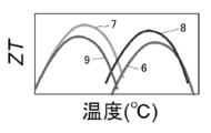
- the figure of merit ZT of the thermoelectric conversion element usually has a mountain-shaped temperature dependence as shown in FIG. 5, and the temperature at which ZT becomes maximum differs depending on the material. Therefore, as shown in FIG. 6, the materials 6 and 8 having the maximum ZT in the high temperature zone are arranged on the high temperature side of the p-type thermoelectric conversion element 4 and the n-type thermoelectric conversion element 5, and the ZT is maximum in the low temperature zone on the low temperature side.
- thermoelectric power generation module When the materials 7 and 9 are arranged, the product of ⁇ T and ZT is increased, and the conversion efficiency ⁇ is higher than that of the thermoelectric power generation module using a single material as shown in FIG.
- a thermoelectric power generation module is called a segment type thermoelectric power generation module, and is also disclosed in Patent Document 1 (Japanese Patent Laid-Open No. 2002-84005) (see particularly paragraphs 0040 to 0041 and FIGS. 10 and 11). . Further, as a result of subsequent research, segment type thermoelectric power generation modules have been developed that can obtain a high conversion efficiency of 11 to 12% by combining various thermoelectric materials.
- the inventors of the present invention formed Ba 8 (Ga, which is a clathrate compound as materials 6 and 8 on the high temperature side of the p-type thermoelectric conversion element 4 and the n-type thermoelectric conversion element 5.
- Ge BGG, type 1
- Ba 8 (Ga, Sn) 46 which is also a clathrate compound as materials 7 and 9 on the low temperature side of the p-type thermoelectric conversion element 4 and the n-type thermoelectric conversion element 5
- a segment type thermoelectric power generation module (see Non-Patent Document 1) using BGT, type 8) was developed.
- BGG whether it is p-type or n-type is determined by the mixing ratio of Ga and Ge, and in BGT, the mixing ratio of Ga and Sn.
- Ba 8 Ga 16 Ge 30 and Ba 8 Ga 18 Ge 28 is p-type
- Ba 8 Ga 14 Ge 32 and Ba 8 Ga 15 Ge 31 becomes n-type
- Ba 8 Ga 16 Sn 30 and Ba 8 Ga 18 Sn 28 Are p-type
- Ba 8 Ga 14 Sn 32 and Ba 8 Ga 15 Sn 31 are n-type.
- An object of the present invention is to achieve a conversion efficiency comparable to that of a segment type thermoelectric power generation module including an environmental load substance, although it is a segment type thermoelectric power generation module using a clathrate compound that does not include an environmental load substance.
- the invention according to claim 1 is a segment type thermoelectric power generation module comprising a p-type thermoelectric conversion element and an n-type thermoelectric conversion element, wherein the n-type thermoelectric conversion element uses a type 2 clathrate compound on the low temperature side, A type 1 clathrate compound or a type 9 clathrate compound is used on the side.
- the invention according to claim 2 is the segment type thermoelectric power generation module according to claim 1, wherein the p-type thermoelectric conversion element uses a type 8 clathrate compound on the low temperature side and a type 1 clathrate compound on the high temperature side. It is characterized by that.
- the invention according to claim 3 is the segment type thermoelectric power generation module according to claim 1 or 2, wherein the type 1 clathrate compound used on the high temperature side of the n-type thermoelectric conversion element has the following composition formula (1) or (2 ).
- the invention according to claim 4 is the segment type thermoelectric power generation module according to any one of claims 1 to 3, wherein the type 9 clathrate compound is represented by any one of the following composition formulas (3) to (5): It is characterized by that. Ba 24 (Ga, Ge) 100 (3) Ba 24 (In, Ge) 100 (4) Ba 24 (Ga, In, Ge) 100 (5)
- the invention according to claim 5 is the segment type thermoelectric power generation module according to any one of claims 1 to 4, wherein the type 2 clathrate compound is represented by any one of the following composition formulas (6) to (8): It is characterized by that. (K, Ba) 24 (Ga, Sn) 136 (6) (K, Ba) 24 (Al, Sn) 136 (7) (K, Ba) 24 (Ga, Sn, Ge) 136 (8)
- a segment type thermoelectric power generation module having higher conversion efficiency than a segment type thermoelectric power generation module using a conventional clathrate compound is provided. can do.
- the high temperature side is a type 9 clathrate compound
- the contact resistance with the type 2 clathrate compound arranged on the low temperature side can be very small, so a segment type thermoelectric power generation module with high conversion efficiency can be obtained.
- the type 2 clathrate compound used on the low temperature side of the n-type thermoelectric conversion element has a large dimensionless figure of merit and can withstand use in a high temperature range exceeding 450 ° C. It is possible to provide a segment type thermoelectric power generation module with high conversion efficiency even under.
- the low temperature side of the p-type thermoelectric conversion element is a type 8 clathrate compound. Since the high temperature side is a type 1 clathrate compound, a segment type thermoelectric power generation module with higher conversion efficiency can be provided.
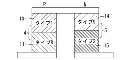
- FIG. 1 The figure which shows the unit structure of the segment type thermoelectric power generation module of Example 1.
- FIG. 2 The figure which shows the unit structure of the segment type thermoelectric power generation module of Example 2.
- FIG. The graph which showed the relationship between temperature difference ((DELTA) T [K]) and conversion efficiency ((eta) [%]) about the segment type thermoelectric power generation module of Examples 1, 2 and a prior art example.
- the figure which shows the unit structure of a segment type thermoelectric power generation module The figure which shows the unit structure of the segment type thermoelectric power generation module using the clathrate compound of a prior art example.
- FIG. 1 is a diagram illustrating a unit structure of a segment type thermoelectric power generation module according to the first embodiment.
- the p-type thermoelectric conversion element 4 of the segment type thermoelectric power generation module of Example 1 uses a type 1 clathrate compound 10 made of Ba 8 Ga 16 Ge 30 or Ba 8 Ga 16 Si 30 on the high temperature side, and Ba 8 on the low temperature side.
- a type 8 clathrate compound 11 which is Ga 16 Sn 30 is used.
- the n-type thermoelectric conversion element 5 of the same module uses a type 1 clathrate compound 12 which is Ba 8 Ga 16 Ge 30 or Ba 8 Ga 16 Si 30 on the high temperature side, and (K, Ba) 24 ( Ga, Sn) 136 , (K, Ba) 24 (Al, Sn) 136 , (K, Ba) 24 (Ga, Sn, Ge) 136, or a part thereof may be converted to Rb, Cs, Sr, Al, In or Ge.
- the type 2 clathrate compound 13 consisting of the compound substituted with is used.
- FIG. 2 is a diagram illustrating a unit structure of the segment type thermoelectric power generation module according to the second embodiment.
- the p-type thermoelectric conversion element 4 of the segment type thermoelectric power generation module of Example 2 uses a type 1 clathrate compound 10 made of Ba 8 Ga 16 Ge 30 or Ba 8 Ga 16 Si 30 on the high temperature side.
- the type 8 clathrate compound 11 which is Ba 8 Ga 16 Sn 30 is used.
- the n-type thermoelectric conversion element 5 of the same module is a type comprising Ba 24 Ga 15 Ge 85 , Ba 24 In 16 Ge 84 or Ba 24 (Ga, In, Ge) 100 which is a mixed crystal thereof on the high temperature side.
- a type 2 clathrate compound 15 comprising 136 or a part thereof substituted with Rb, Cs, Sr, Al, In or Ge is used.
- thermoelectric conversion element 4 shows the conventional example shown in FIG. 7 (p-type thermoelectric conversion element 4 and n-type thermoelectric conversion element 5: type 8 on the low temperature side / type 1 on the high temperature side), and Example 1 (p-type thermoelectric conversion on the high temperature side).
- Element 4 type 8 on the low temperature side / type 1 on the high temperature side
- n-type thermoelectric conversion element 5 type 2 on the low temperature side / type 1 on the high temperature side
- Example 2 shown in FIG.
- thermoelectric conversion element 4 type on the low temperature side
- n-type thermoelectric conversion element 5 low temperature side is type 2 / high temperature side is type 9
- temperature difference ⁇ T [K]
- ⁇ [%] conversion efficiency
- the conversion efficiency of the segment type thermoelectric power generation modules of Examples 1 and 2 is higher than the conversion efficiency of the segment type thermoelectric power generation module of the conventional example at any temperature difference.
- the maximum conversion efficiency is about 10%, and the maximum conversion efficiency of Example 2 is about 9%, which is 1.5% to 2.5% higher than the maximum conversion efficiency of the conventional example.
- a type 1 clathrate compound of (K, Ba) 8 (Ga, Ge) 46 is used as the high temperature side material of the n-type thermoelectric conversion element 5 in Example 1, and the composition ratio of K is set to 2.7, 3.1, and 6.2. Adjustment was made to measure the contact resistance with the low temperature side material. This measurement takes into account the reduction of the contact resistance between the high-temperature side material and the low-temperature side material of the n-type thermoelectric conversion element in order to increase the conversion efficiency in the segment type thermoelectric power generation module using a clathrate compound. went.
- the contact resistance between the low-temperature side material (type 2 clathrate compound) and the high-temperature side material (type 9 clathrate compound) was measured to be 0.003 to 0.01 ⁇ . It was also found that the contact resistance was very small.
- Example 1 and 2 The modification regarding the segment type thermoelectric power generation module of Example 1 and 2 is listed.
- a type 1 clathrate compound comprising Ba 8 (Ga, Ge) 46 or Ba 8 (Ga, Si) 46 on the high temperature side is used as the material of the p-type thermoelectric conversion element. It is also possible to use another type 8 clathrate compound composed of Ba 8 (Ga, Sn) 46 on the low temperature side.
- a type 1 clathrate compound or a type 8 clathrate compound in which 0 to 2 parts of Au, Cu or the like is added may be used.
- a clathrate compound in which two types other than the combination of type 1 and type 8 are combined may be used.
- the high-temperature side material and the low-temperature side material have substantially the same thickness
- the high-temperature side material thickness is set to the low-temperature side.
- the thickness of the material is less than the thickness of the material, but in both the p-type thermoelectric conversion element and the n-type thermoelectric conversion element, depending on the material used on the high temperature side and the low temperature side, the usage environment of the segment type thermoelectric power generation module, etc. It is good to adjust the thickness.
- the temperature distribution of the thermoelectric conversion element is such that the temperature at which ZT is maximized in the central portion of the material on the high temperature side and the temperature at which ZT is maximized also in the central portion of the material on the low temperature side.
- Example 1 the type 1 clathrate compound 12 which is Ba 8 Ga 16 Ge 30 or Ba 8 Ga 16 Si 30 is used on the high temperature side of the n-type thermoelectric conversion element 5, and (K, Ba ) 24 (Ga, Sn) 136 , (K, Ba) 24 (Al, Sn) 136 , (K, Ba) 24 (Ga, Sn, Ge) 136 or a part of them may be replaced with Rb, Cs, Sr, Al,
- the type 2 clathrate compound 13 made of In or Ge is used, but the high temperature side material may be a type 1 clathrate compound represented by another composition formula, and the low temperature side material may be other A type 2 clathrate compound represented by a composition formula may be used.
- Ba 8 Ga 16 Ge 30 or Ba 8 Ga 16 Si 30 may be an n-type type 1 clathrate compound represented by Ba 8 (Ga, Ge) 46 or Ba 8 (Ga, Si) 46 , respectively. . (5) In Example 2, Ba 24 Ga 15 Ge 85 , Ba 24 In 16 Ge 84 or a mixed crystal Ba 24 (Ga, In, Ge) 100 on the high temperature side of the n-type thermoelectric conversion element 5 is used.
- the type 9 clathrate compound may be used, and the material on the low temperature side may be a type 2 clathrate compound represented by another composition formula.
- Ba 24 Ga 15 Ge 85 or Ba 24 In 16 Ge 84 may be an n-type type 9 clathrate compound represented by Ba 24 (Ga, Ge) 100 or Ba 24 (In, Ge) 100 , respectively. .
Landscapes
- Chemical & Material Sciences (AREA)
- Inorganic Chemistry (AREA)
- Silicon Compounds (AREA)
Abstract
本発明は、異なるタイプのクラスレート化合物を接合してなる変換効率の高いセグメント型熱電発電モジュールの提供を目的としている。 本発明に係るセグメント型熱電発電モジュールは、p型熱電変換素子とn型熱電変換素子よりなっている。 そして、p型熱電変換素子は、低温側にタイプ8クラスレート化合物を用い、高温側にタイプ1クラスレート化合物を用いており、n型熱電変換素子は、低温側にタイプ2クラスレート化合物、高温側にタイプ1クラスレート化合物を用いている。 また、n型熱電変換素子の高温側にはタイプ9クラスレート化合物を用いても良い。
Description
この発明は、クラスレート化合物を利用したセグメント型熱電発電モジュールに関するものである。
熱電発電モジュールの単位構造は、図4に示すように高温側電極1と低温側電極2、3との間にp型熱電変換素子4とn型熱電変換素子5を配置したものである。
このような熱電発電モジュールへの熱入力Qにより、両電極に温度差をつけたまま保持すると、p型熱電変換素子4では正孔が、n型熱電変換素子5では電子が、高温側から低温側に移動し、p型熱電変換素子4が配置された低温側電極2からn型熱電変換素子5が配置された低温側電極3に向かって電流が流れ電気出力Pが得られる。
この時、熱電発電モジュールの変換効率ηは、η=P/Qとなる。
なお、通常は昇圧のために、この組み合わせを多段に直接接続する。
このような熱電発電モジュールへの熱入力Qにより、両電極に温度差をつけたまま保持すると、p型熱電変換素子4では正孔が、n型熱電変換素子5では電子が、高温側から低温側に移動し、p型熱電変換素子4が配置された低温側電極2からn型熱電変換素子5が配置された低温側電極3に向かって電流が流れ電気出力Pが得られる。
この時、熱電発電モジュールの変換効率ηは、η=P/Qとなる。
なお、通常は昇圧のために、この組み合わせを多段に直接接続する。
熱電発電モジュールの変換効率ηは、概して温度差ΔTと熱電変換素子の性能指数ZTの積に比例する。
ここで、熱電変換素子の性能指数ZTは、通常図5のように山型の温度依存性を有するとともに、材料によってZTが最大となる温度が異なっている。
したがって、図6のようにp型熱電変換素子4とn型熱電変換素子5の高温側に高温帯でZTが最大となる材料6、8を配置し、低温側に低温帯でZTが最大となる材料7、9を配置するとΔTとZTの積が大きくなり、図4のような単一の材料を用いる熱電発電モジュールよりも変換効率ηが高くなる。
このような熱電発電モジュールをセグメント型熱電発電モジュールと呼んでおり、特許文献1(特開2002-84005号公報)にも開示されている(特に、段落0040~0041及び図10、11を参照)。
また、その後の研究により、種々の熱電材料を組み合わせることによって、11~12%の高い変換効率の得られるセグメント型熱電発電モジュールも開発されてきている。
ここで、熱電変換素子の性能指数ZTは、通常図5のように山型の温度依存性を有するとともに、材料によってZTが最大となる温度が異なっている。
したがって、図6のようにp型熱電変換素子4とn型熱電変換素子5の高温側に高温帯でZTが最大となる材料6、8を配置し、低温側に低温帯でZTが最大となる材料7、9を配置するとΔTとZTの積が大きくなり、図4のような単一の材料を用いる熱電発電モジュールよりも変換効率ηが高くなる。
このような熱電発電モジュールをセグメント型熱電発電モジュールと呼んでおり、特許文献1(特開2002-84005号公報)にも開示されている(特に、段落0040~0041及び図10、11を参照)。
また、その後の研究により、種々の熱電材料を組み合わせることによって、11~12%の高い変換効率の得られるセグメント型熱電発電モジュールも開発されてきている。
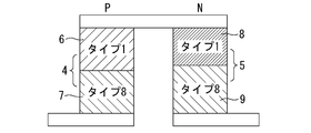
本発明者らは、この発明に先立ち図7に示すように、p型熱電変換素子4とn型熱電変換素子5の高温側に、材料6、8としてクラスレート化合物であるBa8(Ga,Ge)46(BGG、タイプ1)を用いるとともに、p型熱電変換素子4とn型熱電変換素子5の低温側に材料7、9として同じくクラスレート化合物であるBa8(Ga,Sn)46(BGT、タイプ8)を用いたセグメント型熱電発電モジュール(非特許文献1を参照)を開発した。
なお、BGGにおいてはGaとGeの配合比率によって、BGTにおいてはGaとSnの配合比率によって、p型となるかn型となるかが決まる。
例えば、Ba8Ga16Ge30及びBa8Ga18Ge28はp型、Ba8Ga14Ge32及びBa8Ga15Ge31はn型となり、Ba8Ga16Sn30及びBa8Ga18Sn28はp型、Ba8Ga14Sn32及びBa8Ga15Sn31はn型となる。
そして、このセグメント型熱電発電モジュールは、ΔT=570Kにおいてη=7.4%の変換効率を達成している。
なお、BGGにおいてはGaとGeの配合比率によって、BGTにおいてはGaとSnの配合比率によって、p型となるかn型となるかが決まる。
例えば、Ba8Ga16Ge30及びBa8Ga18Ge28はp型、Ba8Ga14Ge32及びBa8Ga15Ge31はn型となり、Ba8Ga16Sn30及びBa8Ga18Sn28はp型、Ba8Ga14Sn32及びBa8Ga15Sn31はn型となる。
そして、このセグメント型熱電発電モジュールは、ΔT=570Kにおいてη=7.4%の変換効率を達成している。
第62回応用物理学会春季学術講演会,13a-A22-10,「クラスレート化合物を用いたセグメント型素子の熱電発電特性」(山口大学)(2015)
しかし、これまでのところ、高い変換効率の得られるセグメント型熱電発電モジュールは、いずれもPb、Te、Sb等の環境負荷物質を母体元素とする熱電材料を利用しているため実用化が困難であった。
この発明は、環境負荷物質を含まないクラスレート化合物を用いるセグメント型熱電発電モジュールでありながら、環境負荷物質を含むセグメント型熱電発電モジュールに匹敵する変換効率の達成を課題としてなされたものである。
この発明は、環境負荷物質を含まないクラスレート化合物を用いるセグメント型熱電発電モジュールでありながら、環境負荷物質を含むセグメント型熱電発電モジュールに匹敵する変換効率の達成を課題としてなされたものである。
請求項1に係る発明は、p型熱電変換素子とn型熱電変換素子よりなるセグメント型熱電発電モジュールであって、前記n型熱電変換素子は、低温側にタイプ2クラスレート化合物を用い、高温側にタイプ1クラスレート化合物又はタイプ9クラスレート化合物を用いたことを特徴とする。
請求項2に係る発明は、請求項1に記載のセグメント型熱電発電モジュールにおいて、前記p型熱電変換素子は、低温側にタイプ8クラスレート化合物を用い、高温側にタイプ1クラスレート化合物を用いたことを特徴とする。
請求項3に係る発明は、請求項1又は2に記載のセグメント型熱電発電モジュールにおいて、前記n型熱電変換素子の高温側に用いるタイプ1クラスレート化合物は、下記組成式(1)又は(2)で表されることを特徴とする。
Ba8(Ga,Ge)46・・・・(1)
Ba8(Ga,Si)46・・・・(2)
Ba8(Ga,Ge)46・・・・(1)
Ba8(Ga,Si)46・・・・(2)
請求項4に係る発明は、請求項1~3のいずれかに記載のセグメント型熱電発電モジュールにおいて、前記タイプ9クラスレート化合物は、下記組成式(3)~(5)のいずれかで表されることを特徴とする。
Ba24(Ga,Ge)100・・・・・(3)
Ba24(In,Ge)100・・・・・(4)
Ba24(Ga,In,Ge)100・・・(5)
Ba24(Ga,Ge)100・・・・・(3)
Ba24(In,Ge)100・・・・・(4)
Ba24(Ga,In,Ge)100・・・(5)
請求項5に係る発明は、請求項1~4のいずれかに記載のセグメント型熱電発電モジュールにおいて、前記タイプ2クラスレート化合物は、下記組成式(6)~(8)のいずれかで表されることを特徴とする。
(K,Ba)24(Ga,Sn)136・・・・・(6)
(K,Ba)24(Al,Sn)136・・・・・(7)
(K,Ba)24(Ga,Sn,Ge)136・・・(8)
(K,Ba)24(Ga,Sn)136・・・・・(6)
(K,Ba)24(Al,Sn)136・・・・・(7)
(K,Ba)24(Ga,Sn,Ge)136・・・(8)
請求項1又は請求項1を引用する請求項3~5のいずれかに係る発明によれば、従来のクラスレート化合物を利用したセグメント型熱電発電モジュールより変換効率の高いセグメント型熱電発電モジュールを提供することができる。
特に、高温側をタイプ9クラスレート化合物とした場合、低温側に配置してあるタイプ2クラスレート化合物との接触抵抗を非常に小さくすることができるので、変換効率の高いセグメント型熱電発電モジュールを提供できる可能性がある。
また、n型熱電変換素子の低温側に用いたタイプ2クラスレート化合物は、無次元性能指数が大きく、450℃を超える高い温度域での使用に耐えるので、低温側電極の温度を低くできない環境下でも変換効率の高いセグメント型熱電発電モジュールを提供することができる。
特に、高温側をタイプ9クラスレート化合物とした場合、低温側に配置してあるタイプ2クラスレート化合物との接触抵抗を非常に小さくすることができるので、変換効率の高いセグメント型熱電発電モジュールを提供できる可能性がある。
また、n型熱電変換素子の低温側に用いたタイプ2クラスレート化合物は、無次元性能指数が大きく、450℃を超える高い温度域での使用に耐えるので、低温側電極の温度を低くできない環境下でも変換効率の高いセグメント型熱電発電モジュールを提供することができる。
請求項2又は請求項2を引用する請求項3~5のいずれかに係る発明によれば、請求項1に係る発明による効果に加え、p型熱電変換素子の低温側をタイプ8クラスレート化合物とし、高温側をタイプ1クラスレート化合物としているので、さらに変換効率の高いセグメント型熱電発電モジュールを提供することができる。
以下、実施例によって本発明の実施形態を説明する。
図1は実施例1のセグメント型熱電発電モジュールの単位構造を示す図である。
実施例1のセグメント型熱電発電モジュールのp型熱電変換素子4は、高温側にBa8Ga16Ge30又はBa8Ga16Si30からなるタイプ1クラスレート化合物10を用い、低温側にBa8Ga16Sn30であるタイプ8クラスレート化合物11を用いている。
また、同モジュールのn型熱電変換素子5は、高温側にBa8Ga16Ge30又はBa8Ga16Si30であるタイプ1クラスレート化合物12を用い、低温側に(K,Ba)24(Ga,Sn)136、(K,Ba)24(Al,Sn)136、(K,Ba)24(Ga,Sn,Ge)136又はそれらの一部をRb,Cs,Sr,Al,In若しくはGeで置換したものからなるタイプ2クラスレート化合物13を用いている。
実施例1のセグメント型熱電発電モジュールのp型熱電変換素子4は、高温側にBa8Ga16Ge30又はBa8Ga16Si30からなるタイプ1クラスレート化合物10を用い、低温側にBa8Ga16Sn30であるタイプ8クラスレート化合物11を用いている。
また、同モジュールのn型熱電変換素子5は、高温側にBa8Ga16Ge30又はBa8Ga16Si30であるタイプ1クラスレート化合物12を用い、低温側に(K,Ba)24(Ga,Sn)136、(K,Ba)24(Al,Sn)136、(K,Ba)24(Ga,Sn,Ge)136又はそれらの一部をRb,Cs,Sr,Al,In若しくはGeで置換したものからなるタイプ2クラスレート化合物13を用いている。
図2は実施例2のセグメント型熱電発電モジュールの単位構造を示す図である。
実施例2のセグメント型熱電発電モジュールのp型熱電変換素子4は、実施例1と同様、高温側にBa8Ga16Ge30又はBa8Ga16Si30からなるタイプ1クラスレート化合物10を用い、低温側にBa8Ga16Sn30であるタイプ8クラスレート化合物11を用いている。
また、同モジュールのn型熱電変換素子5は、高温側にBa24Ga15Ge85、Ba24In16Ge84又はそれらの混晶化物であるBa24(Ga,In,Ge)100からなるタイプ9クラスレート化合物14を用い、低温側に(K,Ba)24(Ga,Sn)136、(K,Ba)24(Al,Sn)136、(K,Ba)24(Ga,Sn,Ge)136又はそれらの一部をRb,Cs,Sr,Al,In若しくはGeで置換したものからなるタイプ2クラスレート化合物15を用いている。
実施例2のセグメント型熱電発電モジュールのp型熱電変換素子4は、実施例1と同様、高温側にBa8Ga16Ge30又はBa8Ga16Si30からなるタイプ1クラスレート化合物10を用い、低温側にBa8Ga16Sn30であるタイプ8クラスレート化合物11を用いている。
また、同モジュールのn型熱電変換素子5は、高温側にBa24Ga15Ge85、Ba24In16Ge84又はそれらの混晶化物であるBa24(Ga,In,Ge)100からなるタイプ9クラスレート化合物14を用い、低温側に(K,Ba)24(Ga,Sn)136、(K,Ba)24(Al,Sn)136、(K,Ba)24(Ga,Sn,Ge)136又はそれらの一部をRb,Cs,Sr,Al,In若しくはGeで置換したものからなるタイプ2クラスレート化合物15を用いている。
図3は、図7に示した従来例(p型熱電変換素子4及びn型熱電変換素子5:低温側がタイプ8/高温側がタイプ1)、図1に示した実施例1(p型熱電変換素子4:低温側がタイプ8/高温側がタイプ1、n型熱電変換素子5:低温側がタイプ2/高温側がタイプ1)及び図2に示した実施例2(p型熱電変換素子4:低温側がタイプ8/高温側がタイプ1、n型熱電変換素子5:低温側がタイプ2/高温側がタイプ9)について、高温側電極と低温側電極との温度差(ΔT[K])と変換効率(η[%])の関係を示したグラフである。
なお、実施例1の測定値は□で、実施例2の測定値は△で、従来例の測定値は◇でプロットしてある。
なお、実施例1の測定値は□で、実施例2の測定値は△で、従来例の測定値は◇でプロットしてある。
このグラフから分かるように、実施例1及び2のセグメント型熱電発電モジュールの変換効率は、いずれの温度差においても従来例のセグメント型熱電発電モジュールの変換効率より高くなっており、実施例1の最大変換効率は約10%、実施例2の最大変換効率は約9%と、従来例の最大変換効率より1.5%~2.5%向上している。
次に、実施例1におけるn型熱電変換素子5の高温側材料に(K,Ba)8(Ga,Ge)46のタイプ1クラスレート化合物を用い、Kの組成比率を2.7、3.1、6.2に調整して、低温側材料との接触抵抗を測定した。
この測定は、クラスレート化合物を用いるセグメント型熱電発電モジュールにおいて、変換効率を上げるにはn型熱電変換素子の高温側材料と低温側材料との接触抵抗の低減が重要であることを考慮して行った。
その結果、K=2.7では0.1~0.2Ω、K=3.1では0.1Ω、K=6.2では0.04~0.06Ωとなり、K=6.2とすることで接触抵抗を最も小さくできることが分かった。
また、実施例2におけるn型熱電変換素子5についても、低温側材料(タイプ2クラスレート化合物)と高温側材料(タイプ9クラスレート化合物)との接触抵抗を測定したところ、0.003~0.01Ωと接触抵抗が非常に小さいことも分かった。
この測定は、クラスレート化合物を用いるセグメント型熱電発電モジュールにおいて、変換効率を上げるにはn型熱電変換素子の高温側材料と低温側材料との接触抵抗の低減が重要であることを考慮して行った。
その結果、K=2.7では0.1~0.2Ω、K=3.1では0.1Ω、K=6.2では0.04~0.06Ωとなり、K=6.2とすることで接触抵抗を最も小さくできることが分かった。
また、実施例2におけるn型熱電変換素子5についても、低温側材料(タイプ2クラスレート化合物)と高温側材料(タイプ9クラスレート化合物)との接触抵抗を測定したところ、0.003~0.01Ωと接触抵抗が非常に小さいことも分かった。
実施例1及び2のセグメント型熱電発電モジュールに関する変形例を列記する。
(1)実施例1及び2においては、p型熱電変換素子の材料として、高温側に他のBa8(Ga,Ge)46又はBa8(Ga,Si)46からなるタイプ1クラスレート化合物を用い、低温側に他のBa8(Ga,Sn)46からなるタイプ8クラスレート化合物を用いても良い。
また、これらにAu、Cu等を0~2部添加したタイプ1クラスレート化合物やタイプ8クラスレート化合物を用いても良い。
さらに、タイプ1とタイプ8との組み合わせ以外の2つのタイプを組み合わせたクラスレート化合物を用いても良い。
(2)実施例1及び2においては、p型熱電変換素子では高温側の材料と低温側の材料の厚さをほぼ同じとし、n型熱電変換素子では高温側の材料の厚さを低温側の材料の厚さより薄くしたが、p型熱電変換素子及びn型熱電変換素子のいずれにおいても、高温側と低温側に用いる材料やセグメント型熱電発電モジュールの利用環境等に応じて、それぞれの材料の厚さを調整すると良い。
具体的には、熱電変換素子の温度分布が、高温側の材料の中央部においてZTが最大となる温度になるとともに、低温側の材料の中央部においてもZTが最大となる温度になるようにすると良い。
(3)実施例1におけるn型熱電変換素子5の高温側材料と低温側材料との接触抵抗を測定した結果からみて、実施例1のセグメント型熱電発電モジュールにおいて、n型熱電変換素子5の高温側材料を、K6.2Ba1.8(Ga,Ge)46のタイプ1クラスレート化合物に変更すれば、変換効率が上がると予想される。
(1)実施例1及び2においては、p型熱電変換素子の材料として、高温側に他のBa8(Ga,Ge)46又はBa8(Ga,Si)46からなるタイプ1クラスレート化合物を用い、低温側に他のBa8(Ga,Sn)46からなるタイプ8クラスレート化合物を用いても良い。
また、これらにAu、Cu等を0~2部添加したタイプ1クラスレート化合物やタイプ8クラスレート化合物を用いても良い。
さらに、タイプ1とタイプ8との組み合わせ以外の2つのタイプを組み合わせたクラスレート化合物を用いても良い。
(2)実施例1及び2においては、p型熱電変換素子では高温側の材料と低温側の材料の厚さをほぼ同じとし、n型熱電変換素子では高温側の材料の厚さを低温側の材料の厚さより薄くしたが、p型熱電変換素子及びn型熱電変換素子のいずれにおいても、高温側と低温側に用いる材料やセグメント型熱電発電モジュールの利用環境等に応じて、それぞれの材料の厚さを調整すると良い。
具体的には、熱電変換素子の温度分布が、高温側の材料の中央部においてZTが最大となる温度になるとともに、低温側の材料の中央部においてもZTが最大となる温度になるようにすると良い。
(3)実施例1におけるn型熱電変換素子5の高温側材料と低温側材料との接触抵抗を測定した結果からみて、実施例1のセグメント型熱電発電モジュールにおいて、n型熱電変換素子5の高温側材料を、K6.2Ba1.8(Ga,Ge)46のタイプ1クラスレート化合物に変更すれば、変換効率が上がると予想される。
(4)実施例1においては、n型熱電変換素子5の高温側にBa8Ga16Ge30又はBa8Ga16Si30であるタイプ1クラスレート化合物12を用い、低温側に(K,Ba)24(Ga,Sn)136、(K,Ba)24(Al,Sn)136、(K,Ba)24(Ga,Sn,Ge)136又はそれらの一部をRb,Cs,Sr,Al,In若しくはGeで置換したものからなるタイプ2クラスレート化合物13を用いているが、高温側の材料は他の組成式で表されるタイプ1クラスレート化合物としても良く、低温側の材料は他の組成式で表されるタイプ2クラスレート化合物としても良い。
また、Ba8Ga16Ge30又はBa8Ga16Si30は、それぞれBa8(Ga,Ge)46又はBa8(Ga,Si)46で表されるn型のタイプ1クラスレート化合物としても良い。
(5)実施例2においては、n型熱電変換素子5の高温側にBa24Ga15Ge85、Ba24In16Ge84又はそれらの混晶化物であるBa24(Ga,In,Ge)100からなるタイプ9クラスレート化合物14を用い、低温側に(K,Ba)24(Ga,Sn)136、(K,Ba)24(Al,Sn)136、(K,Ba)24(Ga,Sn,Ge)136又はそれらの一部をRb,Cs,Sr,Al,In若しくはGeで置換したものからなるタイプ2クラスレート化合物15を用いているが、高温側の材料は他の組成式で表されるタイプ9クラスレート化合物としても良く、低温側の材料は他の組成式で表されるタイプ2クラスレート化合物としても良い。
また、Ba24Ga15Ge85又はBa24In16Ge84は、それぞれBa24(Ga,Ge)100又はBa24(In,Ge)100で表されるn型のタイプ9クラスレート化合物としても良い。
また、Ba8Ga16Ge30又はBa8Ga16Si30は、それぞれBa8(Ga,Ge)46又はBa8(Ga,Si)46で表されるn型のタイプ1クラスレート化合物としても良い。
(5)実施例2においては、n型熱電変換素子5の高温側にBa24Ga15Ge85、Ba24In16Ge84又はそれらの混晶化物であるBa24(Ga,In,Ge)100からなるタイプ9クラスレート化合物14を用い、低温側に(K,Ba)24(Ga,Sn)136、(K,Ba)24(Al,Sn)136、(K,Ba)24(Ga,Sn,Ge)136又はそれらの一部をRb,Cs,Sr,Al,In若しくはGeで置換したものからなるタイプ2クラスレート化合物15を用いているが、高温側の材料は他の組成式で表されるタイプ9クラスレート化合物としても良く、低温側の材料は他の組成式で表されるタイプ2クラスレート化合物としても良い。
また、Ba24Ga15Ge85又はBa24In16Ge84は、それぞれBa24(Ga,Ge)100又はBa24(In,Ge)100で表されるn型のタイプ9クラスレート化合物としても良い。
1 高温側電極 2、3 低温側電極 4 p型熱電変換素子
5 n型熱電変換素子 6、8 高温帯でZTが最大となる材料
7、9 低温帯でZTが最大となる材料
10 タイプ1クラスレート化合物 11 タイプ8クラスレート化合物
12 タイプ1クラスレート化合物 13 タイプ2クラスレート化合物
14 タイプ9クラスレート化合物 15 タイプ2クラスレート化合物
P 電気出力 Q 熱入力 η 変換効率
ΔT 温度差 ZT 性能指数
5 n型熱電変換素子 6、8 高温帯でZTが最大となる材料
7、9 低温帯でZTが最大となる材料
10 タイプ1クラスレート化合物 11 タイプ8クラスレート化合物
12 タイプ1クラスレート化合物 13 タイプ2クラスレート化合物
14 タイプ9クラスレート化合物 15 タイプ2クラスレート化合物
P 電気出力 Q 熱入力 η 変換効率
ΔT 温度差 ZT 性能指数
Claims (5)
- p型熱電変換素子とn型熱電変換素子よりなるセグメント型熱電発電モジュールであって、
前記n型熱電変換素子は、低温側にタイプ2クラスレート化合物を用い、高温側にタイプ1クラスレート化合物又はタイプ9クラスレート化合物を用いた
ことを特徴とするセグメント型熱電発電モジュール。 - 前記p型熱電変換素子は、低温側にタイプ8クラスレート化合物を用い、高温側にタイプ1クラスレート化合物を用いた
ことを特徴とする請求項1に記載のセグメント型熱電発電モジュール。 - 前記n型熱電変換素子の高温側に用いるタイプ1クラスレート化合物は、下記組成式(1)又は(2)で表される
ことを特徴とする請求項1又は2に記載のセグメント型熱電発電モジュール。
Ba8(Ga,Ge)46・・・・(1)
Ba8(Ga,Si)46・・・・(2) - 前記タイプ9クラスレート化合物は、下記組成式(3)~(5)のいずれかで表される
ことを特徴とする請求項1~3のいずれかに記載のセグメント型熱電発電モジュール。
Ba24(Ga,Ge)100・・・・・(3)
Ba24(In,Ge)100・・・・・(4)
Ba24(Ga,In,Ge)100・・・(5) - 前記タイプ2クラスレート化合物は、下記組成式(6)~(8)のいずれかで表される
ことを特徴とする請求項1~4のいずれかに記載のセグメント型熱電発電モジュール。
(K,Ba)24(Ga,Sn)136・・・・・(6)
(K,Ba)24(Al,Sn)136・・・・・(7)
(K,Ba)24(Ga,Sn,Ge)136・・・(8)
Applications Claiming Priority (2)
| Application Number | Priority Date | Filing Date | Title |
|---|---|---|---|
| JP2017-047721 | 2017-03-13 | ||
| JP2017047721A JP6820556B2 (ja) | 2017-03-13 | 2017-03-13 | セグメント型熱電発電モジュール |
Publications (1)
| Publication Number | Publication Date |
|---|---|
| WO2018168568A1 true WO2018168568A1 (ja) | 2018-09-20 |
Family
ID=63523114
Family Applications (1)
| Application Number | Title | Priority Date | Filing Date |
|---|---|---|---|
| PCT/JP2018/008521 Ceased WO2018168568A1 (ja) | 2017-03-13 | 2018-03-06 | セグメント型熱電発電モジュール |
Country Status (2)
| Country | Link |
|---|---|
| JP (1) | JP6820556B2 (ja) |
| WO (1) | WO2018168568A1 (ja) |
Cited By (2)
| Publication number | Priority date | Publication date | Assignee | Title |
|---|---|---|---|---|
| CN115697012A (zh) * | 2022-09-21 | 2023-02-03 | 太原理工大学 | 基于热电材料的多功能热防护结构 |
| EP4440287A1 (en) | 2023-03-29 | 2024-10-02 | Akademia Gorniczo-Hutnicza im. Stanislawa Staszica w Krakowie | Thermoelectric converter based on functionally graded materials |
Citations (6)
| Publication number | Priority date | Publication date | Assignee | Title |
|---|---|---|---|---|
| JP2006344833A (ja) * | 2005-06-09 | 2006-12-21 | Kyoto Univ | 熱電変換材料 |
| JP2007095897A (ja) * | 2005-09-28 | 2007-04-12 | Toshiba Corp | 半導体装置とその製造方法 |
| JP2009081286A (ja) * | 2007-09-26 | 2009-04-16 | Toyota Motor Corp | 熱電変換モジュール |
| US20100275963A1 (en) * | 2009-05-01 | 2010-11-04 | Gm Global Technology Operations, Inc. | Thermoelectric material including a multiple transition metal-doped type i clathrate crystal structure |
| JP2012508466A (ja) * | 2008-11-04 | 2012-04-05 | イートン コーポレーション | 住宅用及び工業用建物のための熱電併給システム(chp) |
| JP2016178249A (ja) * | 2015-03-20 | 2016-10-06 | 国立大学法人山口大学 | タイプ2クラスレート化合物及び該化合物よりなる熱電変換素子 |
-
2017
- 2017-03-13 JP JP2017047721A patent/JP6820556B2/ja active Active
-
2018
- 2018-03-06 WO PCT/JP2018/008521 patent/WO2018168568A1/ja not_active Ceased
Patent Citations (6)
| Publication number | Priority date | Publication date | Assignee | Title |
|---|---|---|---|---|
| JP2006344833A (ja) * | 2005-06-09 | 2006-12-21 | Kyoto Univ | 熱電変換材料 |
| JP2007095897A (ja) * | 2005-09-28 | 2007-04-12 | Toshiba Corp | 半導体装置とその製造方法 |
| JP2009081286A (ja) * | 2007-09-26 | 2009-04-16 | Toyota Motor Corp | 熱電変換モジュール |
| JP2012508466A (ja) * | 2008-11-04 | 2012-04-05 | イートン コーポレーション | 住宅用及び工業用建物のための熱電併給システム(chp) |
| US20100275963A1 (en) * | 2009-05-01 | 2010-11-04 | Gm Global Technology Operations, Inc. | Thermoelectric material including a multiple transition metal-doped type i clathrate crystal structure |
| JP2016178249A (ja) * | 2015-03-20 | 2016-10-06 | 国立大学法人山口大学 | タイプ2クラスレート化合物及び該化合物よりなる熱電変換素子 |
Non-Patent Citations (3)
| Title |
|---|
| KISHIMOTO, KENGO ET AL.: "Thermoelectric properties of sintered type-2 clathrates (K, Ba)24(Ga, Sn)136 with various carrier concentrations", JOURNAL OF APPLIED PHYSICS, vol. 118, 22 September 2015 (2015-09-22), pages 125103 - 1, XP012200693 * |
| OKAMOTO, NORIHIKO ET AL.: "Atomic Displacement Parameters of Guest Atoms and Lattice Thermal Conductivity in Ba-Ga-Ge Clathrate Compounds", MATERIA JAPAN, vol. 46, no. 7, 1 July 2007 (2007-07-01), pages 487 - 491, XP055554084 * |
| TSUCHIYA , YOHEI ET AL., THERMOELECTRIC POWER GENERATION PROPERTIES OF SEGMENTED MODULES USING CLATHRATE COMPOUNDS, February 2015 (2015-02-01) * |
Cited By (2)
| Publication number | Priority date | Publication date | Assignee | Title |
|---|---|---|---|---|
| CN115697012A (zh) * | 2022-09-21 | 2023-02-03 | 太原理工大学 | 基于热电材料的多功能热防护结构 |
| EP4440287A1 (en) | 2023-03-29 | 2024-10-02 | Akademia Gorniczo-Hutnicza im. Stanislawa Staszica w Krakowie | Thermoelectric converter based on functionally graded materials |
Also Published As
| Publication number | Publication date |
|---|---|
| JP2018152464A (ja) | 2018-09-27 |
| JP6820556B2 (ja) | 2021-01-27 |
Similar Documents
| Publication | Publication Date | Title |
|---|---|---|
| Shi et al. | Global band convergence design for high-performance thermoelectric power generation in Zintls | |
| Schmitt et al. | Resolving the true band gap of ZrNiSn half-Heusler thermoelectric materials | |
| Reshak | Thermoelectric properties for AA-and AB-stacking of a carbon nitride polymorph (C 3 N 4) | |
| Zheng et al. | Optoelectronic characteristics of a near infrared light photodetector based on a topological insulator Sb 2 Te 3 film | |
| Fang et al. | Electronic structure and thermoelectric properties of p-type half-Heusler compound NbFeSb: a first-principles study | |
| Johnson et al. | Improved thermoelectric properties in Zn-doped Ca 5 Ga 2 Sb 6 | |
| Sun et al. | Enhanced thermoelectric performance of layered SnS crystals: the synergetic effect of temperature and carrier concentration | |
| Toriyama et al. | Are topological insulators promising thermoelectrics? | |
| WO2015174462A1 (ja) | 熱電変換素子及び熱電変換モジュール | |
| JP6820556B2 (ja) | セグメント型熱電発電モジュール | |
| Chen et al. | Computational prediction of high thermoelectric performance in p-type CuGaTe2 with a first-principles study | |
| Chauhan et al. | Facile fabrication of p-and n-type half-Heusler alloys with enhanced thermoelectric performance and low specific contact resistance employing spark plasma sintering | |
| Rahman et al. | Thermoelectric properties of n and p-type cubic and tetragonal XTiO3 (X= Ba, Pb): A density functional theory study | |
| US11251353B2 (en) | Thermoelectric material, thermoelectric module, and producing method of thermoelectric material | |
| Fu et al. | Thickness dependence of microstructure and thermoelectric performance in Ag2Se films | |
| US2953616A (en) | Thermoelectric compositions and devices utilizing them | |
| KR102269404B1 (ko) | 셀레늄 함량이 증가된 열전소재 | |
| KR20180128186A (ko) | 열전모듈 | |
| KR20170010647A (ko) | 열전 소자 및 이를 포함하는 냉각 장치 | |
| US3414405A (en) | Alloys for making thermoelectric devices | |
| KR102366388B1 (ko) | 열전 소자 | |
| KR102273056B1 (ko) | 구리가 도핑된 열전소재 | |
| Hor et al. | The low temperature thermoelectric properties of CuxTiSe2− ySy | |
| US3050574A (en) | Thermoelectric elements having graded energy gap | |
| KR20190009469A (ko) | P형 열전재료, n형 열전재료 및 열전모듈 |
Legal Events
| Date | Code | Title | Description |
|---|---|---|---|
| 121 | Ep: the epo has been informed by wipo that ep was designated in this application |
Ref document number: 18767839 Country of ref document: EP Kind code of ref document: A1 |
|
| NENP | Non-entry into the national phase |
Ref country code: DE |
|
| 122 | Ep: pct application non-entry in european phase |
Ref document number: 18767839 Country of ref document: EP Kind code of ref document: A1 |