WO2018168377A1 - Paper sheet processing device - Google Patents
Paper sheet processing device Download PDFInfo
- Publication number
- WO2018168377A1 WO2018168377A1 PCT/JP2018/006353 JP2018006353W WO2018168377A1 WO 2018168377 A1 WO2018168377 A1 WO 2018168377A1 JP 2018006353 W JP2018006353 W JP 2018006353W WO 2018168377 A1 WO2018168377 A1 WO 2018168377A1
- Authority
- WO
- WIPO (PCT)
- Prior art keywords
- storage box
- box
- unit
- banknote
- side wall
- Prior art date
Links
- 238000003860 storage Methods 0.000 claims description 282
- 230000004308 accommodation Effects 0.000 claims description 27
- 238000000034 method Methods 0.000 claims description 10
- 230000000630 rising effect Effects 0.000 claims 1
- 230000007246 mechanism Effects 0.000 description 30
- 238000003780 insertion Methods 0.000 description 14
- 230000037431 insertion Effects 0.000 description 14
- 238000009825 accumulation Methods 0.000 description 11
- 238000001514 detection method Methods 0.000 description 6
- 230000010354 integration Effects 0.000 description 3
- 230000002093 peripheral effect Effects 0.000 description 3
- 238000007789 sealing Methods 0.000 description 3
- XEEYBQQBJWHFJM-UHFFFAOYSA-N Iron Chemical compound [Fe] XEEYBQQBJWHFJM-UHFFFAOYSA-N 0.000 description 2
- 238000000151 deposition Methods 0.000 description 2
- 239000000463 material Substances 0.000 description 2
- 239000002184 metal Substances 0.000 description 2
- 229910052751 metal Inorganic materials 0.000 description 2
- NJPPVKZQTLUDBO-UHFFFAOYSA-N novaluron Chemical compound C1=C(Cl)C(OC(F)(F)C(OC(F)(F)F)F)=CC=C1NC(=O)NC(=O)C1=C(F)C=CC=C1F NJPPVKZQTLUDBO-UHFFFAOYSA-N 0.000 description 2
- 239000011347 resin Substances 0.000 description 2
- 229920005989 resin Polymers 0.000 description 2
- 238000004891 communication Methods 0.000 description 1
- 230000006835 compression Effects 0.000 description 1
- 238000007906 compression Methods 0.000 description 1
- 230000000881 depressing effect Effects 0.000 description 1
- 239000000428 dust Substances 0.000 description 1
- 238000000605 extraction Methods 0.000 description 1
- 239000004744 fabric Substances 0.000 description 1
- 230000002452 interceptive effect Effects 0.000 description 1
- 229910052742 iron Inorganic materials 0.000 description 1
- 238000004519 manufacturing process Methods 0.000 description 1
- 230000000149 penetrating effect Effects 0.000 description 1
- 238000003825 pressing Methods 0.000 description 1
- 230000007723 transport mechanism Effects 0.000 description 1
Images


Classifications
-
- B—PERFORMING OPERATIONS; TRANSPORTING
- B65—CONVEYING; PACKING; STORING; HANDLING THIN OR FILAMENTARY MATERIAL
- B65H—HANDLING THIN OR FILAMENTARY MATERIAL, e.g. SHEETS, WEBS, CABLES
- B65H39/00—Associating, collating, or gathering articles or webs
- B65H39/10—Associating articles from a single source, to form, e.g. a writing-pad
-
- B—PERFORMING OPERATIONS; TRANSPORTING
- B65—CONVEYING; PACKING; STORING; HANDLING THIN OR FILAMENTARY MATERIAL
- B65H—HANDLING THIN OR FILAMENTARY MATERIAL, e.g. SHEETS, WEBS, CABLES
- B65H31/00—Pile receivers
- B65H31/22—Pile receivers removable or interchangeable
-
- B—PERFORMING OPERATIONS; TRANSPORTING
- B65—CONVEYING; PACKING; STORING; HANDLING THIN OR FILAMENTARY MATERIAL
- B65H—HANDLING THIN OR FILAMENTARY MATERIAL, e.g. SHEETS, WEBS, CABLES
- B65H29/00—Delivering or advancing articles from machines; Advancing articles to or into piles
- B65H29/38—Delivering or advancing articles from machines; Advancing articles to or into piles by movable piling or advancing arms, frames, plates, or like members with which the articles are maintained in face contact
- B65H29/40—Members rotated about an axis perpendicular to direction of article movement, e.g. star-wheels formed by S-shaped members
-
- B—PERFORMING OPERATIONS; TRANSPORTING
- B65—CONVEYING; PACKING; STORING; HANDLING THIN OR FILAMENTARY MATERIAL
- B65H—HANDLING THIN OR FILAMENTARY MATERIAL, e.g. SHEETS, WEBS, CABLES
- B65H31/00—Pile receivers
- B65H31/04—Pile receivers with movable end support arranged to recede as pile accumulates
- B65H31/08—Pile receivers with movable end support arranged to recede as pile accumulates the articles being piled one above another
- B65H31/10—Pile receivers with movable end support arranged to recede as pile accumulates the articles being piled one above another and applied at the top of the pile
-
- B—PERFORMING OPERATIONS; TRANSPORTING
- B65—CONVEYING; PACKING; STORING; HANDLING THIN OR FILAMENTARY MATERIAL
- B65H—HANDLING THIN OR FILAMENTARY MATERIAL, e.g. SHEETS, WEBS, CABLES
- B65H31/00—Pile receivers
- B65H31/04—Pile receivers with movable end support arranged to recede as pile accumulates
- B65H31/12—Devices relieving the weight of the pile or permitting or effecting movement of the pile end support during piling
- B65H31/18—Positively-acting mechanical devices
-
- B—PERFORMING OPERATIONS; TRANSPORTING
- B65—CONVEYING; PACKING; STORING; HANDLING THIN OR FILAMENTARY MATERIAL
- B65H—HANDLING THIN OR FILAMENTARY MATERIAL, e.g. SHEETS, WEBS, CABLES
- B65H31/00—Pile receivers
- B65H31/30—Arrangements for removing completed piles
- B65H31/3054—Arrangements for removing completed piles by moving the surface supporting the lowermost article of the pile, e.g. by using belts or rollers
- B65H31/3063—Arrangements for removing completed piles by moving the surface supporting the lowermost article of the pile, e.g. by using belts or rollers by special supports like carriages, containers, trays, compartments, plates or bars, e.g. moved in a closed loop
-
- G—PHYSICS
- G07—CHECKING-DEVICES
- G07D—HANDLING OF COINS OR VALUABLE PAPERS, e.g. TESTING, SORTING BY DENOMINATIONS, COUNTING, DISPENSING, CHANGING OR DEPOSITING
- G07D11/00—Devices accepting coins; Devices accepting, dispensing, sorting or counting valuable papers
- G07D11/10—Mechanical details
- G07D11/12—Containers for valuable papers
-
- G—PHYSICS
- G07—CHECKING-DEVICES
- G07D—HANDLING OF COINS OR VALUABLE PAPERS, e.g. TESTING, SORTING BY DENOMINATIONS, COUNTING, DISPENSING, CHANGING OR DEPOSITING
- G07D11/00—Devices accepting coins; Devices accepting, dispensing, sorting or counting valuable papers
- G07D11/10—Mechanical details
- G07D11/14—Inlet or outlet ports
-
- G—PHYSICS
- G07—CHECKING-DEVICES
- G07D—HANDLING OF COINS OR VALUABLE PAPERS, e.g. TESTING, SORTING BY DENOMINATIONS, COUNTING, DISPENSING, CHANGING OR DEPOSITING
- G07D11/00—Devices accepting coins; Devices accepting, dispensing, sorting or counting valuable papers
- G07D11/40—Device architecture, e.g. modular construction
-
- B—PERFORMING OPERATIONS; TRANSPORTING
- B65—CONVEYING; PACKING; STORING; HANDLING THIN OR FILAMENTARY MATERIAL
- B65H—HANDLING THIN OR FILAMENTARY MATERIAL, e.g. SHEETS, WEBS, CABLES
- B65H2301/00—Handling processes for sheets or webs
- B65H2301/40—Type of handling process
- B65H2301/42—Piling, depiling, handling piles
- B65H2301/422—Handling piles, sets or stacks of articles
- B65H2301/4225—Handling piles, sets or stacks of articles in or on special supports
- B65H2301/42254—Boxes; Cassettes; Containers
-
- B—PERFORMING OPERATIONS; TRANSPORTING
- B65—CONVEYING; PACKING; STORING; HANDLING THIN OR FILAMENTARY MATERIAL
- B65H—HANDLING THIN OR FILAMENTARY MATERIAL, e.g. SHEETS, WEBS, CABLES
- B65H2402/00—Constructional details of the handling apparatus
- B65H2402/50—Machine elements
- B65H2402/51—Joints, e.g. riveted or magnetic joints
-
- B—PERFORMING OPERATIONS; TRANSPORTING
- B65—CONVEYING; PACKING; STORING; HANDLING THIN OR FILAMENTARY MATERIAL
- B65H—HANDLING THIN OR FILAMENTARY MATERIAL, e.g. SHEETS, WEBS, CABLES
- B65H2405/00—Parts for holding the handled material
- B65H2405/10—Cassettes, holders, bins, decks, trays, supports or magazines for sheets stacked substantially horizontally
- B65H2405/11—Parts and details thereof
- B65H2405/114—Side, i.e. portion parallel to the feeding / delivering direction
- B65H2405/1144—Side, i.e. portion parallel to the feeding / delivering direction extendible
-
- B—PERFORMING OPERATIONS; TRANSPORTING
- B65—CONVEYING; PACKING; STORING; HANDLING THIN OR FILAMENTARY MATERIAL
- B65H—HANDLING THIN OR FILAMENTARY MATERIAL, e.g. SHEETS, WEBS, CABLES
- B65H2405/00—Parts for holding the handled material
- B65H2405/10—Cassettes, holders, bins, decks, trays, supports or magazines for sheets stacked substantially horizontally
- B65H2405/12—Parts to be handled by user
-
- B—PERFORMING OPERATIONS; TRANSPORTING
- B65—CONVEYING; PACKING; STORING; HANDLING THIN OR FILAMENTARY MATERIAL
- B65H—HANDLING THIN OR FILAMENTARY MATERIAL, e.g. SHEETS, WEBS, CABLES
- B65H2405/00—Parts for holding the handled material
- B65H2405/30—Other features of supports for sheets
- B65H2405/31—Supports for sheets fully removable from the handling machine, e.g. cassette
-
- B—PERFORMING OPERATIONS; TRANSPORTING
- B65—CONVEYING; PACKING; STORING; HANDLING THIN OR FILAMENTARY MATERIAL
- B65H—HANDLING THIN OR FILAMENTARY MATERIAL, e.g. SHEETS, WEBS, CABLES
- B65H2405/00—Parts for holding the handled material
- B65H2405/30—Other features of supports for sheets
- B65H2405/35—Means for moving support
- B65H2405/353—Means for moving support vertically
-
- B—PERFORMING OPERATIONS; TRANSPORTING
- B65—CONVEYING; PACKING; STORING; HANDLING THIN OR FILAMENTARY MATERIAL
- B65H—HANDLING THIN OR FILAMENTARY MATERIAL, e.g. SHEETS, WEBS, CABLES
- B65H2701/00—Handled material; Storage means
- B65H2701/10—Handled articles or webs
- B65H2701/19—Specific article or web
- B65H2701/1912—Banknotes, bills and cheques or the like
Definitions
- the present invention relates to a paper sheet processing apparatus.
- Patent Document 2 a paper sheet processing apparatus having a bundling mechanism that can seal a banknote of a specific denomination accumulated in each stacker unit in units of a specified number has been proposed.
- the bundle of banknotes accumulated in the storage is in a state in which the ends of the banknotes are not neatly aligned at the time of stacking or taking out. )), It is necessary for the operator to align the front and rear ends of each bundle of bills, which is a burden on the operator.
- the paper sheet processing apparatus described in Patent Document 2 requires a bundling mechanism for bundling stacked banknotes separately from the stacker unit. For this reason, the paper sheet processing apparatus is increased in size and cost, which is not preferable in terms of commercial and practical use.
- the present invention has been made to solve such a problem, and can be easily taken out in a state in which the end portions of the paper sheets are aligned without binding a plurality of paper sheets accumulated after the processing.
- An object of the present invention is to provide a paper sheet processing apparatus.
- the paper sheet processing apparatus of the present invention is a paper sheet processing apparatus that processes a plurality of paper sheets and accumulates the plurality of processed paper sheets, A processing unit that processes a plurality of paper sheets; and at least one stacking unit that stacks the plurality of paper sheets processed by the processing unit, wherein the stacking unit has a box housing space.
- a storage box having a paper sheet storage space for storing paper sheets.
- the plurality of paper sheets after being processed by the processing unit are stacked in the storage box of the stacking unit.
- the stacking unit in a state where the storage box is set in the box storage space of the stacking unit body, a plurality of paper sheets are stored while suppressing variations in the paper sheet storage space of the storage box.
- the processed paper sheets can be taken out from the stacking unit main body together with the storage box in a state where the respective end portions are neatly stacked and stacked inside the storage box without being bundled. For this reason, since the operator does not directly touch the plurality of stacked sheets, there is no possibility that the plurality of sheets are distorted when taken out from the stacking unit main body.
- the stacking unit has a top surface that is wide enough to allow the paper sheets to be placed thereon, and is placed inside the storage box so as to be movable in the vertical direction, and the storage box includes the box storage space. It is preferable to further include a placement unit moving unit that moves at least upward with respect to the placement unit.
- a placement unit that is movable in the vertical direction is arranged inside the accommodation box.
- the placement unit is moved to a predetermined upper position by the placement unit moving unit in advance, so that the distance from the opening at the top of the storage box to the placement unit. Can be brought closer.
- the paper sheets are less likely to vary, and the paper sheets can be collected in a state where the edges of the paper sheets are more neatly aligned. become.
- the stacking section descends due to the weight of the paper sheets or the driving force of the stacking section moving section. It becomes possible to accumulate leaves in a form where each end is more neatly arranged.
- the placement unit moving unit includes a moving member that is movable in the vertical direction, and the placing unit can be separated from and attached to the moving member.
- the placement unit can be separated from and moved with respect to the movable member that can move in the vertical direction, the placement unit can be moved up and down by the movable member and is positioned in the storage box. Thus, it can be separated from the moving member.
- the magnet is provided on one or both sides, and the magnet detachably connects the mounting portion and the moving member in a state where the storage box is stored in the box storage space, and the storage box is connected to the box storage space. It is preferably arranged so as to release the connection when it is out of the state.
- the operator inserts the storage box into the box storage space of the stacking unit main body so that the mounting unit in the storage box is detachably connected to the moving member of the mounting unit moving unit by the magnet. Is possible. Therefore, it is possible to easily perform the operation of setting the storage box in the box storage space of the stacking unit main body. In a state where the mounting portion and the moving member are connected, the moving member moves upward, so that the mounting portion can be raised and placed close to the opening at the top of the storage box.
- the operator when taking out the paper sheets stored in the storage box, the operator removes the storage box from the box storage space of the stacking unit main body, thereby releasing the connection between the placement unit and the moving member by the magnet. Is possible. At this time, the placement unit that has been disconnected from the moving member descends inside the storage box while maintaining the state where the paper sheet is placed. Thereby, there is no possibility that paper sheets may spill out from the upper opening of the storage box, and it is possible to easily perform the operation of taking out the storage box containing a plurality of paper sheets from the stacking unit main body.
- a slit for connecting a magnet that extends through the side wall and extends in the vertical direction is formed on the side wall of the storage box, and the magnet connects the mounting portion and the moving member through the slit.
- the magnet can firmly connect the placement portion inside the accommodation box and the moving member of the placement portion moving portion outside the accommodation box through the slit formed in the side wall of the accommodation box. Is possible.
- the magnet moves up and down along the slit following the movement of the moving member up and down, avoid the magnet from coming into contact with the side wall of the storage box even if the moving member moves up and down. Is possible. Therefore, there is no possibility that the connection between the moving member and the mounting portion by the magnet is released when the moving member and the mounting portion are moved up and down.
- the moving member has a support portion having a shape capable of supporting the mounting portion from below while being able to be separated from the mounting portion
- the storage box includes a bottom wall and the bottom A side wall that rises upward from an edge of the wall, and the side wall has a first slit that passes through the side wall and extends in the up-down direction through which the support part can pass, and the bottom wall
- a bottom opening that communicates with the first slit and through which the support portion can pass may be provided.
- the support member of the moving member is lifted by the moving member of the placement unit moving unit.
- the support portion can be inserted into the inside of the storage box through the bottom opening and the first slit on the side wall, and can be raised along the first slit.
- the support portion when the storage box is taken out from the box storage space, if the support portion is lowered manually or automatically, the support portion can be detached from the bottom of the bottom wall of the storage box to the outside of the storage box. Thereby, it is possible to take out the storage box from the stacking unit main body while avoiding interference with the support unit. Further, following the lowering of the support portion, the placement portion can also be lowered and returned to a predetermined lower position. Therefore, when the storage box is taken out from the stacking unit main body, the paper sheets are placed above the storage box. There is no risk of spilling from the opening. As described above, interference between the storage box and the support portion and outflow from the opening of the paper sheets can be avoided, so that the operation of taking out the storage box containing a plurality of paper sheets from the stacking unit main body can be easily performed. Is possible.
- the placement unit moving unit further includes a biasing member that applies an upward biasing force to the moving member.
- the biasing member in a state where the storage box is stored in the box storage space of the stacking unit main body, the biasing member can apply an upward biasing force to the placement unit via the moving member. Thereby, it is possible to raise the placing portion by the urging force of the urging member so as to be close to the opening in the upper portion of the storage box. This eliminates the need for another drive source for raising the placement unit. Further, as the paper sheets are accumulated on the placement section, the placement section gradually descends against the urging force of the urging member due to the weight of the accumulated paper sheets. It is possible to accumulate the paper sheets on the placing portion while aligning the respective end portions. This eliminates the need for another drive source for lowering the placement unit as the paper sheets accumulate on the placement unit. Therefore, it is possible to omit or simplify the drive source for moving the mounting portion in the vertical direction.
- the placement unit moving unit further includes a biasing member that applies an upward biasing force to the moving member, and the side wall has a second slit that communicates with the bottom opening and penetrates the side wall, In a state where the support portion is inserted into the accommodation box, the support portion preferably protrudes outside the accommodation box through the second slit and can be operated downward.
- the moving member when the moving member is lowered, the moving member can be lowered while resisting the urging force of the urging member by pushing the supporting portion of the moving member downward with a finger. This eliminates the need for a drive source for lowering the moving member. Further, since the moving member can be lifted by the urging force of the urging member, a driving source for moving the moving member other than the urging member becomes unnecessary, and the configuration of the mounting portion moving unit is simplified.
- the support portion protrudes to the outside of the storage box through the second slit even when it is inserted into the storage box. Therefore, by pushing the support portion downward with a finger, the support portion and the support portion while resisting the urging force of the urging member while maintaining the state in which the support portion supports the placement portion from below inside the storage box Both mounting parts can be lowered.
- the storage box has a bottom wall that is movable in the vertical direction, and a side wall that can be expanded and contracted in the vertical direction as the bottom wall moves in the vertical direction, and the upper end of the side wall is formed inside the box storage space. It is preferable to further include a support portion that supports the predetermined height.
- the storage box by moving the bottom wall of the storage box in the vertical direction, the storage box can be deformed between a state where the storage box is extended in the vertical direction and a state where the storage box is folded.
- the storage box in a folded state is inserted into the box storage space, and the upper end of the side wall of the storage box is supported at a predetermined height by the support unit. Further, the driving force of the mounting unit moving unit and the side wall itself If the bottom wall is disposed at a predetermined upper position by the elastic force of the box, it is possible to attach the storage box in a folded state at a position above the box storage space.
- the paper sheets are less likely to vary, and the paper sheets can be collected in a state where the ends of the paper sheets are more neatly aligned.
- the bottom wall is lowered by the weight of the paper sheets or the driving force of the loading unit moving unit, so that the side wall is stretched in the vertical direction.
- the storage box can be easily stored and transported if it is in a folded state when it is empty and does not contain paper sheets.
- the paper sheet processing apparatus of the present invention it is possible to easily take out a plurality of paper sheets accumulated after processing in a state where the end portions of the paper sheets are aligned without being bundled. it can.
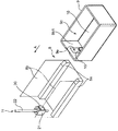
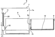
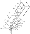
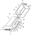
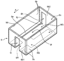
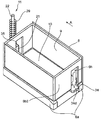
- FIG. 2 is an explanatory perspective view illustrating an arrangement of a storage box, a box guide, and a table moving unit in FIG. 1. It is a perspective view of the storage box and banknote accumulation table of FIG. It is a perspective view of the table moving part of FIG. It is a cross-sectional explanatory drawing which shows the process of inserting the accommodation box of FIG. 1 in a box accommodation space.
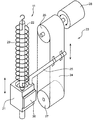
- FIG. 6 is a cross-sectional explanatory view showing a state in which the banknote accumulation table side magnet and the linear bush side magnet of FIG. 5 are attracted.
- FIG. 6 is an explanatory cross-sectional view showing an operation of raising the banknote stacking table and the linear bush of FIG.
- FIG. 6 is a cross-sectional explanatory view showing a state in which the banknote stacking table and the linear bush are lowered as banknotes are stacked on the banknote stacking table of FIG. 5.
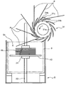
- FIG. 9 is a cross-sectional explanatory view showing a state in which bills are fed onto a banknote stacking table using an impeller in a configuration in which an impeller is provided above the storage box of FIG. 8 as a modified example of the present invention.
- FIG. 6 is a cross-sectional explanatory view showing a state where the accumulation of banknotes in the storage box of FIG. 5 is completed.
- FIG. 11 is an explanatory cross-sectional view illustrating a state in which the storage of the banknote stacking table is lowered while the suction of the magnet on the banknote stacking table side and the magnet on the linear bushing side is released while the storage box of FIG. 10 is being extracted from the box guide.
- FIG. 12 is a cross-sectional explanatory view showing a state in which the storage box of FIG. 11 is completely extracted from the box guide and taken out of the box storage space.
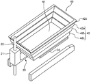
- the support arm of a moving member is arrange
- FIG. 15 It is a perspective view of the storage box and banknote accumulation table of FIG. It is sectional explanatory drawing which shows the state by which the banknote integration
- an operation unit operable with a finger is provided at the tip of the support arm of the moving member, and a slit into which the operation unit can be inserted is formed on the side wall of the storage box. It is an isometric view explanatory drawing which shows the comprised structure.
- FIG. 18 is an explanatory perspective view showing an operation of manually lowering the banknote stacking table supported from below by the support arm by pushing down the operation portion at the tip of the support arm of FIG. 17 from the outside of the storage box with a finger.
- FIG. 22 is a perspective explanatory view showing a process of attaching the folded storage box of FIG. 21 to the box guide.
- FIG. 23 is a perspective explanatory view showing a state in which the upper end portion of the side wall of the storage box in the folded state in FIG. 22 is supported by the upper end surface of the box guide. It is a perspective explanatory view showing a state where the storage box of FIG. 23 extends as banknotes are accumulated.
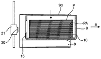
- the banknote handling apparatus 1 performs processing such as authentication of a plurality of banknotes P and identification of denominations, and stacks a plurality of banknotes P after processing to collect stacked banknotes PA. It is an apparatus to form.
- the banknote processing apparatus 1 includes an apparatus main body 2, a deposit unit 3, a processing unit 4 that performs processing such as discrimination of authenticity and denomination, and a temporary storage unit that temporarily holds a processed banknote P. 5, a plurality of stacking units 6 that are stacking units that stack banknotes P under conditions such as denominations, a control unit 12, a banknote detection sensor 13 that detects banknotes P sent to each stacking unit 6, And a box detection sensor 14 for detecting the presence of the storage box 9 in each integrated unit 6.
- banknotes P that are collectively inserted into the depositing unit 3 are transported one by one along a transport path R1 and R2 by a transport mechanism (not shown).
- the processing unit 4 performs processing such as authentication of the banknote P and determination of the denomination.
- the processed banknote P is temporarily held in the temporary storage unit 5 and then sent to the transport path R2, or directly sent to the transport path R2 without going through the temporary storage unit 5.
- the banknotes P are classified and sent to one of the plurality of stacking units 6 along the transport path R2 based on the discrimination result of the authenticity and denomination in the processing unit 4, and the storage box of the stacking unit 6 9 is accumulated.
- the banknotes P may be classified according to old and new conditions. In that case, the new banknotes are reused by another device outside the banknote processing apparatus 1 (for example, an automatic teller machine (ATM or the like)). To be recovered.
- ATM automatic teller machine
- the stacking unit 6 is a unit that stacks a plurality of banknotes P processed by the processing unit 4 to form a stacked banknote PA. Note that the banknote handling apparatus 1 only needs to include at least one stacking unit 6, and the number of stacking units 6 is not limited in the present invention.
- the stacking unit 6 includes a stacking unit body 7, a box guide 8, a storage box 9, a bill stacking table 10, and a table moving unit 11.
- the integrated unit main body 7 has a box accommodation space 7 a having a capacity capable of accommodating the accommodation box 9.
- the storage box 9 can be taken in and out of the box storage space 7a through an opening 7b formed on the front side of the integrated unit main body 7.
- a box guide 8 for guiding when the storage box 9 is taken in and out is attached to the box storage space 7a.
- the box guide 8 includes a pair of support blocks 8 a that support the storage box 9 from below, and a pair of guide plates 8 b that support the storage box 9 from both the left and right sides.
- the storage box 9 is a rectangular parallelepiped hollow box having an opening 9d at the upper end, and has a bottom area suitable for the size of the bill P.
- the storage box 9 has a rectangular bottom wall 9a and four side walls 9b that rise upward from the four edges of the bottom wall 9a.
- a rectangular parallelepiped banknote accommodating space 9c is formed by the bottom wall 9a and the four side walls 9b.
- the storage box 9 has an outer dimension that can be taken in and out of the box storage space 7a.
- the opening 9d formed at the upper end of the storage box 9 has an opening area through which the bills P can pass.
- the banknote storage space 9c has a volume capable of storing the stacked banknotes PA, which are a plurality of banknotes stacked in the vertical direction. Since the banknote storage space 9c inside the storage box 9 is smaller than the box storage space 7a, the banknotes P inserted into the banknote storage space 9c are less likely to vary than when the banknotes are inserted into the box storage space 7a. . Therefore, it is possible to stack the banknotes P in a state where they are neatly arranged inside the banknote storage space 9c.
- a slit 9e that penetrates the side wall 9b1 and extends in the vertical direction is formed in the side wall 9b1 on the front side in the insertion direction A in which the storage box 9 is inserted into the box storage space 7a.
- the slit 9e is a slit for connecting a magnet 15 (described later) fixed to the banknote stacking table 10 to a magnet 30 on the linear bush 21 side.
- the accommodation box 9 only needs to be capable of accommodating and transporting the accumulated banknote PA, and is formed of a material such as a resin or a thin metal plate.
- the storage box 9 has a shape and strength that can be stacked, because the stacked bills PA can be easily stored and transported.
- the opening 9d of the storage box 9 only needs to be formed in the upper part of the storage box 9, and is not limited to being formed in the upper end of the storage box 9.
- a slit-shaped opening may be formed in the side wall 9a.
- the banknote stacking table 10 is a rectangular plate-like member, and has an upper surface 10 a having a width on which banknotes P can be placed.
- the banknote stacking table 10 is arranged so as to be movable in the vertical direction inside the storage box 9.
- the banknote stacking table 10 is manufactured from a resin or a thin metal plate.
- the banknote accumulation table 10 that is a rectangular plate-like member is described as an example, but the upper surface on which the banknote P can be placed is provided. As long as it can move in the vertical direction inside the storage box 9, it may be a mounting portion of another shape.
- the table moving unit 11 has a configuration for moving the banknote stacking table 10 at least upward in a state where the storage box 9 is stored in the box storage space 7a.
- the table moving unit 11 corresponds to the placement unit moving unit of the present invention.
- the table moving unit 11 is disposed on the front side of the box guide 8 in the insertion direction A in which the storage box 9 is inserted into the box storage space 7a.
- the table moving unit 11 includes a linear bush 21 that constitutes a moving member that can move in the vertical direction, a guide rod 22 that guides the linear bush 21 in the vertical direction, A drive mechanism 23 that moves the bush 21 in the vertical direction and a tension coil spring 29 that is an urging member that applies an upward urging force to the linear bush 21 are provided.
- the guide rod 22 is fixed such as the bottom surface of the box housing space 7a of the integrated unit main body 7 in a state where the guide rod 22 is vertically extended.
- the linear bush 21 has a through-hole penetrating in the vertical direction, and is, for example, a substantially rectangular parallelepiped member. The linear bush 21 can move in the vertical direction while being guided by the guide rod 22 by inserting the guide rod 22 into the through hole.
- the drive mechanism 23 may have any configuration as long as it has a function of moving the linear bush 21 in the vertical direction.
- the drive mechanism 23 shown in FIG. 4 includes an endless belt 24 that is closed in an annular shape, a connecting rod 25 that connects the outer peripheral surface of the endless belt 24 and the linear bush 21, and a central axis that extends in the horizontal direction.
- the drive pulley 26 and the driven pulley 27 are arranged in this manner, and the motor 28 is capable of rotationally driving the drive pulley 26 in both the forward and reverse directions.
- the driving pulley 26 and the driven pulley 27 are arranged apart from each other in the vertical direction so as to be arranged in parallel with the guide rod 22.
- the endless belt 24 is wound around a drive pulley 26 and a driven pulley 27, and is installed between the pair of pulleys 26 and 27 so as to extend in parallel with the guide rod 22.
- the endless belt 24 travels between the driving pulley 26 and the driven pulley 27 in a direction corresponding to the rotational direction of the driving pulley 26.
- the linear bush 21 connected to the endless belt 24 via the connecting rod 25 can move in any one of the vertical directions.
- the drive of the motor 28 of the drive mechanism 23 is controlled by the control unit 12, and specific control will be described in detail in the operation description of the integrated unit at the subsequent stage.
- various drive mechanisms such as a mechanism having a linear motor capable of linear drive in the vertical direction are employed as the drive mechanism 23 for moving the linear bush 21 in the vertical direction. May be.
- the tension coil spring 29 is a biasing member that applies an upward biasing force to the linear bush 21.
- the lower end of the tension coil spring 29 is fixed to the linear bush 21, and the upper end is fixed to the guide rod 22, the inner wall of the integrated unit main body 7, and the like. Therefore, in a state where the linear bush 21 is not pushed downward by the drive mechanism 23, the linear bush 21 is on standby in a state where the linear bush 21 is pushed up to a predetermined upper position by the urging force of the tension coil spring 29.
- the tension coil spring 29 is described as an example of the urging member of the present invention, but the present invention is not limited to this. Any biasing member that can apply an upward biasing force to the linear bush 21 constituting the moving member is included in the biasing member of the present invention.
- an elastic member such as rubber or an air spring may be used as another urging member of the present invention.
- the banknote processing apparatus 1 of this embodiment is provided with the connection part which can connect the banknote stacking table 10 and the linear bush 21 which comprises a moving member so that attachment or detachment is possible.
- the connecting portion is composed of a magnet 15 on the banknote stacking table 10 side and a magnet 30 on the linear bush 21 side.
- magnets 15 and 30 removably connect the banknote stacking table 10 and the linear bush 21 in a state where the storage box 9 is stored in the box storage space 7a (see FIG. 6). It is arranged so as to release the connection when it is out of the space 7a (see FIG. 12).
- the magnet 15 on the banknote stacking table 10 side is attached to the front side in the insertion direction A of the banknote stacking table 10 via a bracket 16.
- the attracting surface of the magnet 15 is arranged in a standing state so as to face the insertion direction A.
- the magnet 15 is exposed to the outside of the storage box 9 through the slit 9e formed in the side wall 9b1 on the front side of the storage box 9 and faces the insertion direction A when the banknote stacking table 10 is stored in the storage box 9. Is arranged.
- the magnet 30 on the linear bush 21 side is attached to the side surface of the linear bush 21 as shown in FIGS.
- the attracting surface of the magnet 30 is arranged in a standing state so as to face the opposite direction to the insertion direction A.
- the banknote stacking table 10 can be separated from the linear bush 21 that can move in the vertical direction. Therefore, the banknote stacking table 10 can be moved up and down by the linear bush 21 and can be positioned in the storage box 9 and away from the linear bush 21.
- the magnets 15 and 30 may be provided on either the banknote stacking table 10 or the linear bush 21, and a magnetic plate such as iron that can be attracted to the magnet 15 or 30 is disposed on the other side. Just do it.
- the banknotes P in the stacking unit 6 are stacked by being sequentially placed on the banknote stacking table 10 that moves in the vertical direction inside the storage box 9. Specifically, as shown in FIGS. 5 to 12, the stacking unit 6 stacks the bills P in the following procedure.
- the linear bush 21 is moved to a predetermined lower position by the drive mechanism 23. Lower and wait.
- the control unit 12 is linear.
- the drive of the motor 28 (see FIG. 3) of the drive mechanism 23 is controlled so that the bush 21 is lowered to a predetermined lower position.
- the tension coil spring 29 is extended as the linear bush 21 is lowered by the drive mechanism 23, whereby elastic energy is accumulated in the tension coil spring 29.
- the storage box 9 is inserted in the box guide 8 inside the box storage space 7 a by being pushed in the insertion direction A by the operator.
- the magnet 15 fixed to the banknote stacking table 10 inside the storage box 9 is attracted to the magnet 30 fixed to the linear bush 21 through the slit 9 e of the storage box 9.
- the banknote stacking table 10 and the linear bush 21 are detachably connected.
- the banknote stacking table 10 and the linear bush 21 are raised to a predetermined upper position.
- the control unit 12 performs control to stop driving of the motor 28 of the drive mechanism 23 so that the drive pulley 26 can idle, and the restoring force of the tension coil spring 29 causes the banknote stacking table 10 and linear
- the bush 21 is raised to a predetermined upper position so that the bills P can be accumulated.
- the banknote stacking table 10 is disposed at a position close to the opening 9 d at the upper end of the storage box 9.
- the banknote stacking table 10 and the linear bush 21 may be raised to a predetermined upper position by driving the motor 28 of the drive mechanism 23.
- the banknotes P that have been processed by the processing unit 4 in FIG. 1 and then sent to the stacking unit 6 are sequentially inserted into the banknote storage space 9c from the opening 9d at the upper end of the storage box 9, as shown in FIG. Then, the bills are stacked on the bill stacking table 10, and the bills P are formed.
- the banknote stacking table 10 gradually descends against the upward biasing force of the tension coil spring 29.
- the banknote stacking table 10 and the linear bush 21 may be gradually lowered by driving the motor 28 of the drive mechanism 23. In this case, the descending amount of the banknote stacking table 10 and the linear bush 21 may be controlled by the control unit 12 based on the number of banknotes P sent to the stacking unit 6 detected by the banknote detection sensor 13.
- an impeller 31 as shown in FIG.
- the impeller 31 includes a cylindrical main body 31a and a plurality of blades 31b extending in a tangential direction of the outer peripheral surface on the cylindrical outer peripheral surface of the main body 31a.
- the bills P are fed into the stacking unit 6, the bills P are sequentially sandwiched between the gaps 31 c between the two adjacent blades 31 b by rotating the impeller 31 counterclockwise by driving a motor (not shown). Moving. Thereby, it is possible to smoothly and sequentially insert the bills P one by one into the storage box 9.
- the transport of banknotes P to the stacking unit 6 is stopped, and the operator Is notified by a detecting means (not shown) such as a buzzer or a lamp.
- the counting of the banknotes P in each stacking unit 6 may be performed by the control unit 12 based on the detection signal of the banknote detection sensor 13 (see FIG. 1), for example.
- the operator moves the storage box 9 along the extraction direction B and pulls it out of the box guide 8.
- the magnet 15 fixed to the banknote stacking table 10 is pulled away from the magnet 30 fixed to the linear bush 21.
- the connection between the banknote stacking table 10 and the linear bush 21 is released.
- the banknote stacking table 10 and the stacked banknotes PA stacked thereon are lowered inside the storage box 9 by its own weight.
- the state in which the uppermost banknote P of the stacked banknote PA is above the opening 9d at the upper end of the storage box 9 in the state when the stacking is completed in FIG. 10 (see the uppermost banknote P illustrated by the two-dot chain line).
- the banknote stacking table 10 is lowered, whereby the entire stacked banknote PA can be stored in the storage box 9.
- the operator moves the storage box 9 in which the stacked banknotes PA are stored in the take-out direction B and takes it out from the cassette storage space 7 a of the stacking unit main body 7.
- the control unit 12 causes the drive mechanism 23 to lower the linear bush 21 to a predetermined lower position by the drive mechanism 23 so as to return to the standby state of FIG. To control.
- the storage box 9 taken out from the cassette storage space 7a is transported by an operator to another device outside the banknote handling apparatus 1 (for example, an automatic teller machine (ATM)).
- ATM automatic teller machine
- a plurality of banknotes P processed by the processing unit 4 are stacked in the storage box 9 of the stacking unit 6.
- a plurality of banknotes P varies within the banknote storage space 9 c of the storage box 9. It is accommodated while being suppressed. It is possible to accumulate paper with the edges of the paper sheet P aligned neatly.
- the several banknote P after a process is the state of the accumulation
- the stacking unit is not limited by the number of banknotes that can be gripped ergonomically at a time.
- the number of stored bills P in 6 can be increased.
- a process of sealing the accumulated banknote PA becomes unnecessary.
- a bundling mechanism can be abbreviate
- a sealing member such as a rubber band or a tape
- the banknotes P can be stably stacked by accumulating and storing the banknotes P in the storage box 9.
- the stacking unit 6 includes a banknote stacking table 10 and a table moving unit 11.
- the banknote stacking table 10 is arranged so as to be movable in the vertical direction inside the storage box 9.
- the banknote stacking table 10 is moved to a predetermined upper position by the table moving unit 11 in advance, so that the banknote stacking table 10 is opened from the opening 9 d above the storage box 9. It is possible to reduce the distance up to.
- banknotes P when a plurality of banknotes P are inserted into the inside of the banknote storage space 9c of the storage box 9 from the opening 9d, they are less likely to vary, and the banknotes P are accumulated in a state where the ends of the banknotes P are more neatly arranged. Can be formed.
- the banknote stacking table 10 As the banknotes P accumulate on the banknote stacking table 10, the banknote stacking table 10 is lowered by the weight of the banknotes P or the driving force of the motor 28 of the drive mechanism 23. It is possible to accumulate the banknotes P in such a manner that their ends are more neatly aligned.
- the stacking unit 6 includes the banknote stacking table 10 (mounting unit) and the table moving unit 11 (mounting unit moving unit). Is not limited to this.
- a configuration in which the stacking unit does not include a mounting unit and a mounting unit moving unit specifically, a configuration in which the banknote stacking table 10 is not stored in the storage box 9 may be used. In this case, even if the banknote P is inserted into the storage box 9, the banknotes P are neatly collected and stacked as compared with the case where the banknote P is inserted into the box storage space 7a without the storage box 9, and the banknote remains in the stacked state. It can be taken out of the processing apparatus 1.
- the banknote processing apparatus 1 of this embodiment is provided with the connection part which has the magnets 15 and 30 as a connection part which connects the banknote stacking table 10 and the linear bush 21 so that attachment or detachment is possible.
- the magnets 15 and 30 are provided on one or both of the banknote stacking table 10 and the linear bush 21.
- the magnets 15 and 30 detachably connect the banknote stacking table 10 and the linear bush 21 in a state where the storage box 9 is stored in the box storage space 7a, and the storage box 9 protrudes from the box storage space 7a. In such a case, it is arranged so as to release the connection.
- the operator inserts the storage box 9 into the box storage space 7 a of the stacking unit main body 7, whereby the banknote stacking table 10 in the storage box 9 is moved by the magnets 15 and 30 to the linear bush of the table moving unit 11. 21 can be detachably connected. Therefore, it is possible to easily perform the operation of setting the storage box 9 in the box storage space 7a of the integrated unit main body 7.
- the linear bush 21 moves upward so that the banknote stacking table 10 can be raised and placed close to the opening 9d above the storage box 9. is there.
- the operator takes out the storage box 9 from the box storage space 7 a of the stacking unit main body 7, so that the space between the banknote stacking table 10 and the linear bush 21 is removed.
- the connection by the magnets 15 and 30 can be released.
- the banknote stacking table 10 released from the connection with the linear bush 21 is lowered inside the storage box 9 while maintaining the state where the banknote P is placed. Thereby, there is no possibility that the banknote P will spill out from the opening 9d at the top of the storage box 9, and the operation of taking out the storage box 9 storing the stacked banknote PA from the stacking unit main body 7 can be easily performed.
- the side wall 9b1 of the storage box 9 of the present embodiment is formed with a slit 9e for connecting a magnet that extends through the side wall 9b1 and extends in the vertical direction.
- the magnets 15 and 30 pass through the slits 9e formed in the side wall 9b1 of the storage box 9, and the linear bushes of the banknote stacking table 10 inside the storage box 9 and the table moving unit 11 outside the storage box 9 are used. 21 can be firmly connected to each other.
- the magnets 15 and 30 move up and down along the slit 9e following the movement of the linear bush 21 up and down, even if the linear bush 21 moves up and down, the magnets 15 and 30 remain in the storage box.
- the table moving unit 11 has a tension coil spring 29 as an urging member that applies an upward urging force to the linear bush 21.
- the tension coil spring 29 can apply an upward biasing force to the banknote stacking table 10 via the linear bush 21. is there. Thereby, it is possible to raise the banknote stacking table 10 by the urging force of the tension coil spring 29 and arrange it close to the opening 9d at the top of the storage box 9. Therefore, another drive source for raising the banknote stacking table 10 becomes unnecessary.
- the banknote stacking table 10 gradually descends against the urging force of the tension coil spring 29 due to the weight of the stacked banknotes P.
- a plurality of banknotes P can be stacked on the banknote stacking table 10 while aligning the respective end portions. Therefore, the other drive source for lowering the banknote stacking table 10 as the banknotes P are stacked on the banknote stacking table 10 becomes unnecessary. Therefore, it becomes possible to omit or simplify the drive source for moving the banknote stacking table 10 in the vertical direction.
- the banknote processing apparatus 1 of the said embodiment has urging members, such as the tension
- the urging member may not be provided, and it is only necessary to have a drive mechanism 23 that moves the linear bush 21 in the vertical direction.
- the linear bush 21 is moved downward.
- a drive mechanism 23 capable of lowering the bush 21 is necessary.
- the banknote stacking table 10 and the linear bush 21 are detachably connected by the magnets 15 and 20, but the present invention is not limited to this.
- a support arm extending in the horizontal direction from the linear bush 21. 34 may be provided as a support part for supporting the banknote stacking table 10 from below.
- the support arm 34 can raise and lower the banknote stacking table 10 by supporting the banknote stacking table 10 from below while being able to be separated from the banknote stacking table 10.
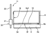
- the table moving unit 11 includes a moving member 35 that is movable in the vertical direction along the guide rod 22. 13 also has the drive mechanism 23 and the tension coil spring 29 shown in FIG. 4, but these are not shown in FIG.
- the moving member 35 shown in FIG. 13 has the linear bush 21 and the support arm 34 described above.
- the support arm 34 extends in the horizontal direction (specifically, the direction opposite to the insertion direction A) from the outer surface of the casing 21 a of the linear bush 21.
- the support arm 34 has a flat plate shape having a flat upper surface capable of supporting the banknote stacking table 10 from below.
- the support arm 34 shown in FIG. 13 includes a pair of a root portion 34a whose one end is connected to the casing 21a, an intermediate portion 34b connected to the other end of the root portion 34a, and a pair branched from the intermediate portion 34b. And a distal end portion 34c. That is, the support arm 34 has a substantially Y shape.
- the banknote stacking table 10 can be placed on the support arm 34, in other words, can be separated from and attached to the support arm 34. Therefore, the banknote stacking table 10 can be moved up and down by the moving member 35, and can be in a state where the banknote collecting table 10 is located in the storage box 9 and away from the moving member 35.
- the support arm 34 may be any shape that can support the banknote stacking table 10 from below and function as a support portion.
- the support arm 34 is not limited to a substantially Y shape, and may have another shape.
- the support arm 34 of the moving member 35 has the box guide 8 in a state before the storage box 9 is inserted into the box guide 8 inside the box storage space 7 a (see FIG. 1). Is disposed at a lower position than the upper surface 8a1 of the support block 8a. Thereby, the storage box 9 can be smoothly inserted into the box guide 8 without contacting the support arm 34.
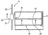
- the storage box 9 shown in FIG. 14 is the same as the storage box 9 shown in FIG. 2 above in that it has a bottom wall 9a and four side walls 9b that rise upward from the edge of the bottom wall 9a. However, it differs in having a bottom opening 9f and a first slit 9i.
- the side wall 9b1 on the front side of the storage box 9 is formed with a first slit 9i for passing through a support arm that extends through the side wall 9b1 and extends in the vertical direction through which the root portion 34a of the support arm 34 can pass.
- the bottom wall 9a is formed with a bottom opening 9f that communicates with the first slit 9i and through which the support arm 34 can pass.
- the bottom opening 9f has a shape corresponding to the shape of the support arm 34 so that the support arm 34 can pass therethrough.
- the bottom opening 9f includes a first portion 9f1 corresponding to the base portion 34a of the support arm 34, a second portion 9f2 corresponding to the intermediate portion 34b, and a pair of third portions corresponding to the pair of tip portions 34c. Part 9f3.
- the first portion 9f1 of the bottom opening 9f communicates with the first slit 9i of the side wall 9b1.
- the banknote processing apparatus configured as described above, in the state where the storage box 9 is stored in the box storage space 7a of the integrated unit body 7 as shown in FIGS. 35 (that is, the linear bush 21 and the support arm 34) is lifted by the tension coil spring 29 or the drive mechanism 23, so that the support arm 34 of the moving member 35 is moved to the bottom opening 9f of the bottom wall 9a of the storage box 9.
- the support arm 34 can be inserted into the housing box 9 through the first slit 9i of the side wall 9b1, and the inside of the housing box 9 can be raised along the first slit 9i.
- the banknote stacking table 10 in the storage box 9 can be supported from below by the support arm 34 of the moving member 35, and the banknote stacking table 10 can be moved in the vertical direction together with the moving member 35.
- the support arm 34 can be moved to the bottom of the storage box 9 by automatically lowering the moving member 35 by driving the motor 28 (see FIG. 4) of the drive mechanism 23 described above. It is possible to leave the housing box 9 from the bottom opening 9f of the wall 9a.
- the operation portion 34d is provided at the tip of the support arm 34, the moving member 35 can be manually lowered by pressing the operation portion 34d with a finger.
- the storage box 9 can be taken out from the integrated unit body 7 while avoiding interference with the support arm 34. Further, following the lowering of the support arm 34, the banknote stacking table 10 can also be lowered and returned to a predetermined lower position, so that when the storage box 9 is taken out from the stacking unit body 7, the banknote P is stored. There is no risk of spilling from the upper opening 9d of the box 9. As described above, the interference between the storage box 9 and the support arm 34 and the outflow of the banknote P from the opening 9d can be avoided, so that the operation of taking out the storage box 9 storing the stacked banknote PA from the stacking unit main body 7 can be easily performed. It is possible to do.
- the banknotes P are accumulated on the support arm 34 even when the storage box 9 is not present. It is possible. In this case, the accumulated banknotes P may be taken out by the operator's hands. Therefore, even when the storage box 9 is insufficient, it is possible to continue the stacking operation of the banknotes P, which is practically preferable.
- the support arm 34 is manually moved.
- the support arm 34 may have an operation part 34d so that it can be pushed down.
- the table moving unit 11 includes a tension coil spring 29 that applies an upward biasing force to the moving member 35.
- the support arm 34 of the moving member 35 has an operation portion 34d that extends in the horizontal direction and can contact the finger and receive a downward operation force from the finger.
- the operating portion 34d is formed by extending the tip of one tip portion 34c of the pair of tip portions 34c of the support arm 34 to the side opposite to the insertion direction A.
- the rear side wall 9b2 in the insertion direction A of the storage box 9 is formed with a second slit 9h through which the operation portion 34d passes, as a slit different from the first slit 9i of the front side wall 9b1.
- the second slit 9h is a slit that extends through the side wall 9b2 and extends in the vertical direction through which the operation unit 34d can pass.
- the second slit 9h communicates with the third portion 9f3 of the bottom opening 9f of the bottom wall 9a through the communication portion 9j.
- the operating portion 34d of the support arm 34 projects outside the storage box 9 through the second slit 9h formed in the side wall 9b2 on the rear side in the insertion direction A when the support arm 34 is inserted into the storage box 9. It is possible.
- the operation portion 34d of the support arm 34 is accommodated through the second slit 9h formed in the side wall 9b2 on the rear side in the insertion direction A even when the support arm 34 is inserted into the accommodation box 9. Projecting outside the box 9. Therefore, by pushing the operating portion 34d downward with a finger, the supporting arm 34 resists the biasing force of the tension coil spring 29 while maintaining the state in which the support arm 34 supports the banknote stacking table 10 from below. However, both the support arm 34 and the banknote stacking table 10 can be lowered. Further, the support arm 34 can be detached from the bottom of the storage box 9 from the bottom opening 9f of the bottom wall 9a of the storage box 9 by being lowered. Thereby, it is possible to easily take out the storage box 9 storing the stacked banknotes PA from the box guide 8 of the box storage space 7 a without interfering with the support arm 34.
- a temporary fixing mechanism such as a ratchet mechanism is provided. You may have.
- the moving member 35 can be temporarily fixed to a predetermined lower position shown in FIG.
- the temporary fixing of the moving member 35 by the temporary fixing mechanism is released by an operation such as depressing the operation portion 34 d again with a finger, the supporting force is supported by the restoring force of the tension coil spring 29.
- the arm 34 and the moving member 35 can be raised.
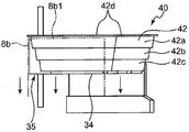
- the storage box 40 may have a configuration that can be expanded and contracted in the vertical direction.
- the storage box 40 includes a bottom wall 41 that can move in the vertical direction, and a side wall that can expand and contract in the vertical direction as the bottom wall 41 moves in the vertical direction. 42.
- the bottom wall 41 has an upper surface on which the bills P can be placed, and a placement portion (for example, the above-described bill stacking) that can move up and down inside the accommodation box 40 (specifically, the space inside the side wall 42). It functions as a mounting portion such as the table 10.
- the bottom wall 41 of the storage box 40 is placed on the support arm 34 of the moving member 35 inside the box storage space 7a.
- the vertically extendable side wall 42 is configured by, for example, overlapping a plurality of tapered frames 42a, 42b, and 42c having different sizes.
- Each of the tapered frames 42a, 42b, and 42c is a rectangular frame and has a shape that tapers toward the lower side.
- the side wall 42 only needs to be extendable in the vertical direction, and may be formed of a bellows-like frame or a frame made of a flexible material such as a hood cloth. Even if the side wall 42 extends like a bellows-like frame, it may be a frame that shrinks by its own elastic force. In that case, the bottom wall 41 can be positioned in the upper position by the elastic force of the side wall 42.
- a flange 42 d that protrudes outward from the side wall 42 is formed.
- the side wall 42 is not limited to the bottom wall 41 being fixed, as long as the side wall 42 can expand and contract in the vertical direction as the bottom wall 41 moves in the vertical direction. Therefore, the bottom wall 41 may be detachable from the side wall 42.
- a box guide 8 is used as a support part for supporting the flange 42d at the upper end of the side wall 42 of the storage box 40 so as to have a predetermined height inside the box storage space 7a.
- the pair of guide plates 8b has an upper end surface 8b1.
- the support portion that supports the flange 42d at the upper end of the side wall 42 may be other than the upper end surface 8b1 of the guide plate 8b.
- the storage box 40 has a bottom wall 41 that can move in the vertical direction and functions as a placing portion on which bills can be placed, and the bottom wall 41. And a side wall 42 that can be expanded and contracted vertically. Further, the guide plate 8b of the box guide 8 has an upper end surface 8b1 as a support portion that supports the upper end of the side wall 42 at a predetermined height inside the box accommodating space 7a. According to such a configuration, by moving the bottom wall 41 of the storage box 40 that functions as a mounting portion on which banknotes are mounted in the up and down direction, the storage box 40 is stretched in the up and down direction and the folded state. It is possible to deform between.
- the folded accommodation box 40 is inserted into the box accommodation space 7a and accommodated by the upper end surface 8b1 of the guide plate 8b.
- the upper end of the side wall 42 of the box 40 is supported so as to have a predetermined height.
- both sides of the side wall 42 of the storage box 40 are hung by being hooked on the upper end surface 8b1 of the guide plate 8b.
- the bottom wall 41 is disposed at a predetermined upper position by the support arm 34 of the moving member 35 of the table moving unit 11 or by the elastic force of the side wall 42 itself. Thereby, it is possible to attach the storage box 40 in a folded state at a position above the box storage space 7a.
- the storage box 40 in a state where banknotes are stacked and stretched in the vertical direction is taken out from the box storage space 7a as it is and stored in a state where the upper end opening is closed with a lid.
- the storage box 40 may be stored in a state of being hung on a storage shelf having a portion on which the flange 42d at the upper end of the side wall 42 can be hooked.
- the side wall 42 When taking out the banknote accommodated in the storage box 40, if the storage box 40 is placed on a flat surface such as a work table, the side wall 42 is folded by its own weight, so that the banknote inside the storage box 40 is exposed to the outside. Therefore, the banknote can be easily taken out.
- the side wall 42 is separated from the bottom wall 41 by placing the accommodation box 40 on a pedestal having an upper surface that is the same as or smaller than the area of the bottom wall 41. Then, the bill falls below the bottom wall 41 and the bill is exposed to the outside on the pedestal in a state of being placed on the bottom wall 41, so that the work of taking out the bill is further facilitated.
- the storage box 40 can be easily stored and transported if it is folded when it is empty when banknotes are not stored.
- the paper sheets processed by the paper sheet processing apparatus of the present invention are processed with a plurality of paper sheets (for example, discrimination of authenticity and denomination), and a plurality of processed paper sheets are accumulated. Anything can be used. Therefore, the paper sheets referred to in the present invention include not only the banknotes shown in the above embodiment, but also virtual banknotes for games used in checks and game halls.
Landscapes
- Engineering & Computer Science (AREA)
- Mechanical Engineering (AREA)
- Physics & Mathematics (AREA)
- General Physics & Mathematics (AREA)
- Pile Receivers (AREA)
Abstract
Description
4 処理ユニット(処理部)
6 集積ユニット(集積部)
7 集積ユニット本体
7a ボックス収容空間
9、40 収容ボックス
9a、41 底壁
9b、42 側壁
9c 紙幣収容空間
9d 開口
9e マグネット連結用のスリット
9f 底部開口
9i 支持腕通過用の第1スリット
9h 操作部通過用の第2スリット
10 紙幣集積テーブル(載置部)
11 テーブル移動部(載置部移動部)
15 紙幣集積テーブル側マグネット
21 リニアブッシュ(移動部材)
23 駆動機構
29 引張コイルばね(付勢部材)
30 リニアブッシュ側マグネット
34 支持腕(支持部)
35 移動部材
P 紙幣
PA 集積紙幣 1
6 Integration unit (integration unit)
7 Stacking
11 Table moving part (mounting part moving part)
15 Banknote accumulation
23
30
35 Moving member P Bill PA Stacked bill
Claims (9)
- 複数の紙葉類を処理し、処理後の複数の紙葉類を集積する紙葉類処理装置であって、
前記複数の紙葉類を処理する処理部と、
前記処理部で処理された後の前記複数の紙葉類を集積する少なくとも1つの集積部とを備え、
前記集積部は、
ボックス収容空間を有する集積部本体と、
前記ボックス収容空間に出し入れ可能な寸法を有する収容ボックスであって、当該収容ボックスの上部に形成された前記紙葉類が通過可能な大きさの開口、および集積された前記複数の紙葉類を収容する紙葉類収容空間を有する収容ボックスと、
を有している
紙葉類処理装置。 A paper sheet processing apparatus that processes a plurality of paper sheets and accumulates a plurality of processed paper sheets,
A processing unit for processing the plurality of paper sheets;
And at least one stacking unit that stacks the plurality of paper sheets after being processed by the processing unit,
The stacking unit
A stacking unit body having a box housing space;
An accommodation box having a size that can be taken into and out of the box accommodation space, the opening formed in an upper portion of the accommodation box having a size through which the paper sheets can pass, and the plurality of accumulated paper sheets A storage box having a paper storage space for storing;
A paper sheet processing apparatus. - 前記集積部は、
前記紙葉類が載置可能な広さの上面を有し、前記収容ボックスの内部において上下方向に移動可能に配置された載置部と、
前記収容ボックスが前記ボックス収容空間に収容されている状態において、前記載置部に対して少なくとも上方へ移動させる載置部移動部と、
をさらに有している
請求項1に記載の紙葉類処理装置。 The stacking unit
A loading portion that has an upper surface that is wide enough to allow the paper sheets to be loaded, and that is disposed so as to be movable in the vertical direction inside the storage box;
In a state in which the storage box is stored in the box storage space, a mounting unit moving unit that moves at least upward with respect to the mounting unit,
The paper sheet processing apparatus according to claim 1, further comprising: - 前記載置部移動部は、上下方向に移動可能な移動部材を有し、
前記載置部は、前記移動部材に対して離接可能である、
請求項2に記載の紙葉類処理装置。 The placement unit moving unit has a moving member movable in the vertical direction,
The mounting portion is detachable from the moving member.
The paper sheet processing apparatus according to claim 2. - 前記載置部と前記移動部材とを着脱自在に連結する連結部をさらに備え、
前記連結部は、少なくとも1個のマグネットを有し、
前記マグネットは、前記載置部および前記移動部材のいずれか一方または両方に設けられ、
前記マグネットは、前記収容ボックスが前記ボックス収容空間に収容されている状態では前記載置部と前記移動部材とを着脱自在に連結し、前記収容ボックスが前記ボックス収容空間から出ている状態のときには当該連結を解除するように、配置されている、
請求項3に記載の紙葉類処理装置。 A connecting portion that removably connects the placement portion and the moving member;
The connecting portion has at least one magnet,
The magnet is provided on one or both of the mounting portion and the moving member,
The magnet removably connects the mounting portion and the moving member when the storage box is stored in the box storage space, and when the storage box is out of the box storage space. Arranged to release the connection,
The paper sheet processing apparatus according to claim 3. - 前記収容ボックスの側壁には、当該側壁を貫通するとともに上下方向に延びるマグネット連結用のスリットが形成され、
前記マグネットは、前記スリットを通して前記載置部と前記移動部材とを連結する、
請求項4に記載の紙葉類処理装置。 The side wall of the storage box is formed with a slit for connecting a magnet that extends through the side wall and extends in the vertical direction.
The magnet connects the mounting portion and the moving member through the slit,
The paper sheet processing apparatus according to claim 4. - 前記移動部材は、前記載置部から引き離すことが可能な状態で前記載置部を下方から支持することが可能な形状を有する支持部を有し、
前記収容ボックスは、底壁と、当該底壁の縁から上方へ立ち上がる側壁とを有し、
前記側壁は、当該側壁を貫通するとともに前記支持部が通過可能な上下方向に延びる支持部通過用の第1スリットを有し、
前記底壁は、前記第1スリットに連通し、前記支持部が通過可能な底部開口を有する、
請求項3に記載の紙葉類処理装置。 The moving member has a support part having a shape capable of supporting the placement part from below while being able to be separated from the placement part.
The storage box has a bottom wall and a side wall rising upward from an edge of the bottom wall,
The side wall has a first slit for passing a support part that extends through the side wall and extends in the vertical direction through which the support part can pass.
The bottom wall communicates with the first slit and has a bottom opening through which the support portion can pass.
The paper sheet processing apparatus according to claim 3. - 前記載置部移動部は、前記移動部材に上向きの付勢力を与える付勢部材をさらに有する、
請求項3~6のいずれか1項に記載の紙葉類処理装置。 The placement unit moving unit further includes a biasing member that applies an upward biasing force to the moving member.
The paper sheet processing apparatus according to any one of claims 3 to 6. - 前記載置部移動部は、前記移動部材に上向きの付勢力を与える付勢部材をさらに有し、
前記側壁は、前記底部開口に連通し、当該側壁を貫通する第2スリットを有し、
前記支持部は、前記支持部が前記収容ボックスに挿入されている状態では、前記第2スリットを通して前記収容ボックスの外部に突出して下向きに操作可能である、
請求項6に記載の紙葉類処理装置。 The placement unit moving unit further includes a biasing member that applies an upward biasing force to the moving member,
The side wall has a second slit that communicates with the bottom opening and penetrates the side wall;
The support portion can be operated downward by projecting to the outside of the storage box through the second slit in a state where the support portion is inserted into the storage box.
The paper sheet processing apparatus according to claim 6. - 前記収容ボックスは、上下方向に移動可能な底壁と、当該底壁の上下方向の移動に伴って上下方向に伸縮自在の側壁とを有し、
前記ボックス収容空間の内部において前記側壁の上端を所定の高さになるように支持する支持部をさらに備えている、
請求項1に記載の紙葉類処理装置。 The storage box has a bottom wall that can move in the vertical direction, and a side wall that can expand and contract in the vertical direction as the bottom wall moves in the vertical direction.
A support portion for supporting the upper end of the side wall at a predetermined height inside the box housing space;
The paper sheet processing apparatus according to claim 1.
Priority Applications (7)
| Application Number | Priority Date | Filing Date | Title |
|---|---|---|---|
| KR1020197023631A KR102205366B1 (en) | 2017-03-15 | 2018-02-22 | Paper sheet processing device |
| CN201880017099.2A CN110461743B (en) | 2017-03-15 | 2018-02-22 | Paper sheet processing device |
| US16/486,412 US10954095B2 (en) | 2017-03-15 | 2018-02-22 | Paper sheet processing device |
| MX2019007828A MX2019007828A (en) | 2017-03-15 | 2018-02-22 | Paper sheet processing device. |
| EP18767830.5A EP3569532B1 (en) | 2017-03-15 | 2018-02-22 | Paper sheet processing device |
| BR112019013830-7A BR112019013830B1 (en) | 2017-03-15 | 2018-02-22 | PAPER SHEET PROCESSING DEVICE |
| PH12019501916A PH12019501916A1 (en) | 2017-03-15 | 2019-08-16 | Paper sheet processing device |
Applications Claiming Priority (2)
| Application Number | Priority Date | Filing Date | Title |
|---|---|---|---|
| JP2017-049657 | 2017-03-15 | ||
| JP2017049657A JP6762249B2 (en) | 2017-03-15 | 2017-03-15 | Paper leaf processing equipment |
Publications (1)
| Publication Number | Publication Date |
|---|---|
| WO2018168377A1 true WO2018168377A1 (en) | 2018-09-20 |
Family
ID=63523517
Family Applications (1)
| Application Number | Title | Priority Date | Filing Date |
|---|---|---|---|
| PCT/JP2018/006353 WO2018168377A1 (en) | 2017-03-15 | 2018-02-22 | Paper sheet processing device |
Country Status (9)
| Country | Link |
|---|---|
| US (1) | US10954095B2 (en) |
| EP (1) | EP3569532B1 (en) |
| JP (1) | JP6762249B2 (en) |
| KR (1) | KR102205366B1 (en) |
| CN (1) | CN110461743B (en) |
| BR (1) | BR112019013830B1 (en) |
| MX (1) | MX2019007828A (en) |
| PH (1) | PH12019501916A1 (en) |
| WO (1) | WO2018168377A1 (en) |
Families Citing this family (1)
| Publication number | Priority date | Publication date | Assignee | Title |
|---|---|---|---|---|
| KR102030522B1 (en) * | 2018-03-23 | 2019-10-10 | 효성티앤에스 주식회사 | Tray unit assembly |
Citations (6)
| Publication number | Priority date | Publication date | Assignee | Title |
|---|---|---|---|---|
| JPS5129339B2 (en) | 1971-10-12 | 1976-08-25 | ||
| JPS5438093B2 (en) | 1971-11-20 | 1979-11-19 | ||
| JPS5812084A (en) * | 1981-07-16 | 1983-01-24 | 株式会社東芝 | Paper money processor |
| JPS59143832A (en) * | 1983-02-04 | 1984-08-17 | Fujitsu Ltd | Paper sheets detecting mechanism |
| JP2015005023A (en) * | 2013-06-19 | 2015-01-08 | 日立オムロンターミナルソリューションズ株式会社 | Bill cassette |
| JP2016015003A (en) * | 2014-07-02 | 2016-01-28 | 日立オムロンターミナルソリューションズ株式会社 | Bank note storing apparatus |
Family Cites Families (16)
| Publication number | Priority date | Publication date | Assignee | Title |
|---|---|---|---|---|
| JPH0643083Y2 (en) * | 1987-03-02 | 1994-11-09 | グローリー工業株式会社 | Currency storage device |
| JPH01143757U (en) * | 1988-03-25 | 1989-10-03 | ||
| US5219158A (en) * | 1992-09-28 | 1993-06-15 | Xerox Corporation | Two corner sheet stacking apparatus with matching cover |
| US5803704A (en) * | 1994-02-01 | 1998-09-08 | Lockheed Martin Corporation | Apparatus and method for accumulating and transferring one or more stacks of articles |
| JP2742021B2 (en) * | 1994-07-11 | 1998-04-22 | 富士通株式会社 | Stacker device |
| US5803227A (en) * | 1995-06-06 | 1998-09-08 | International Game Technology | Bill stacker |
| JP4631451B2 (en) * | 2005-01-28 | 2011-02-16 | 沖電気工業株式会社 | Medium storage cassette and deposit device |
| US20080099975A1 (en) * | 2006-10-26 | 2008-05-01 | Kabushiki Kaisha Toshiba | Sheet stack loader and sheet loading method |
| WO2009090758A1 (en) | 2008-01-17 | 2009-07-23 | Glory Ltd. | Methods and systems for sorting bank notes, providing a change fund, and balancing revenue |
| US9016687B2 (en) * | 2008-11-25 | 2015-04-28 | Avery Dennison Corporation | Tag stacking system and stack tray and method of making and handling tags |
| WO2010097954A1 (en) | 2009-02-27 | 2010-09-02 | グローリー株式会社 | Device for sorting- and binding-processing of banknotes |
| US8066273B2 (en) * | 2009-12-18 | 2011-11-29 | Ncr Corporation | Dual-stack document storage bin for use in a self-service bunch document depositing terminal |
| JP2012030913A (en) * | 2010-07-29 | 2012-02-16 | Fujifilm Corp | Image forming apparatus |
| JP2012078981A (en) * | 2010-09-30 | 2012-04-19 | Fujitsu Frontech Ltd | Paper sheet processing apparatus |
| CN103456079B (en) * | 2012-05-28 | 2016-08-31 | 冲电气工业株式会社 | Media processing apparatus and medium accommodation cassette |
| CN104044950B (en) * | 2014-04-11 | 2017-05-10 | 上海古鳌电子科技股份有限公司 | Paper sheet accumulating device |
-
2017
- 2017-03-15 JP JP2017049657A patent/JP6762249B2/en active Active
-
2018
- 2018-02-22 CN CN201880017099.2A patent/CN110461743B/en active Active
- 2018-02-22 US US16/486,412 patent/US10954095B2/en active Active
- 2018-02-22 KR KR1020197023631A patent/KR102205366B1/en active IP Right Grant
- 2018-02-22 MX MX2019007828A patent/MX2019007828A/en unknown
- 2018-02-22 EP EP18767830.5A patent/EP3569532B1/en active Active
- 2018-02-22 WO PCT/JP2018/006353 patent/WO2018168377A1/en active Application Filing
- 2018-02-22 BR BR112019013830-7A patent/BR112019013830B1/en active IP Right Grant
-
2019
- 2019-08-16 PH PH12019501916A patent/PH12019501916A1/en unknown
Patent Citations (6)
| Publication number | Priority date | Publication date | Assignee | Title |
|---|---|---|---|---|
| JPS5129339B2 (en) | 1971-10-12 | 1976-08-25 | ||
| JPS5438093B2 (en) | 1971-11-20 | 1979-11-19 | ||
| JPS5812084A (en) * | 1981-07-16 | 1983-01-24 | 株式会社東芝 | Paper money processor |
| JPS59143832A (en) * | 1983-02-04 | 1984-08-17 | Fujitsu Ltd | Paper sheets detecting mechanism |
| JP2015005023A (en) * | 2013-06-19 | 2015-01-08 | 日立オムロンターミナルソリューションズ株式会社 | Bill cassette |
| JP2016015003A (en) * | 2014-07-02 | 2016-01-28 | 日立オムロンターミナルソリューションズ株式会社 | Bank note storing apparatus |
Non-Patent Citations (1)
| Title |
|---|
| See also references of EP3569532A4 |
Also Published As
| Publication number | Publication date |
|---|---|
| EP3569532A1 (en) | 2019-11-20 |
| CN110461743B (en) | 2020-12-15 |
| BR112019013830B1 (en) | 2023-05-09 |
| BR112019013830A2 (en) | 2020-01-28 |
| MX2019007828A (en) | 2019-09-09 |
| EP3569532B1 (en) | 2021-10-20 |
| US20200180895A1 (en) | 2020-06-11 |
| KR20190104594A (en) | 2019-09-10 |
| PH12019501916A1 (en) | 2020-06-08 |
| JP6762249B2 (en) | 2020-09-30 |
| KR102205366B1 (en) | 2021-01-19 |
| CN110461743A (en) | 2019-11-15 |
| EP3569532A4 (en) | 2020-10-28 |
| US10954095B2 (en) | 2021-03-23 |
| JP2018150168A (en) | 2018-09-27 |
Similar Documents
| Publication | Publication Date | Title |
|---|---|---|
| EP2600322B1 (en) | Medium storage box | |
| JPH0215451B2 (en) | ||
| RU2632156C1 (en) | Impeller mechanism, device for stacking and piece of paper and method for processing paper sheets | |
| JP4624057B2 (en) | Banknote handling machine | |
| WO2018168377A1 (en) | Paper sheet processing device | |
| JP5197097B2 (en) | Paper sheet processing equipment | |
| JP6220743B2 (en) | Banknote storage device | |
| KR102104614B1 (en) | Medium stacking and extracting apparatus and control method thereof | |
| BR122022024613B1 (en) | PAPER SHEET PROCESSING DEVICE | |
| JP3325193B2 (en) | Sorter | |
| WO2023175688A1 (en) | Paper sheet storage device | |
| JPH0986706A (en) | Bag separating and picking method and device | |
| KR101686801B1 (en) | Bill counting machine having means for dust collecting | |
| JP2010113497A (en) | Bill processor | |
| JP6832178B2 (en) | Paper leaf processing equipment | |
| JP4766684B2 (en) | Paper transport device | |
| WO2021152666A1 (en) | Paper sheet storing device and paper sheet handling device | |
| JPH02163227A (en) | Paper feeding device enabling manual feeding | |
| JPH06312872A (en) | Bill accumulator for bill processor | |
| JP5955906B2 (en) | Banknote handling equipment | |
| JP3707752B2 (en) | Paper processing equipment | |
| KR20220040771A (en) | finisher in which finishing section and stacking section are detachably connected | |
| JP6301093B2 (en) | Paper sheet stacking apparatus and paper sheet stacking method | |
| JP2000095367A (en) | Card taking-out device | |
| JP5877735B2 (en) | Paper feeding device and image forming apparatus |
Legal Events
| Date | Code | Title | Description |
|---|---|---|---|
| 121 | Ep: the epo has been informed by wipo that ep was designated in this application |
Ref document number: 18767830 Country of ref document: EP Kind code of ref document: A1 |
|
| WWE | Wipo information: entry into national phase |
Ref document number: 122022024613 Country of ref document: BR |
|
| REG | Reference to national code |
Ref country code: BR Ref legal event code: B01A Ref document number: 112019013830 Country of ref document: BR |
|
| ENP | Entry into the national phase |
Ref document number: 20197023631 Country of ref document: KR Kind code of ref document: A |
|
| ENP | Entry into the national phase |
Ref document number: 2018767830 Country of ref document: EP Effective date: 20190814 |
|
| NENP | Non-entry into the national phase |
Ref country code: DE |
|
| ENP | Entry into the national phase |
Ref document number: 112019013830 Country of ref document: BR Kind code of ref document: A2 Effective date: 20190703 |