WO2018168296A1 - 板状磁気作業体及びこれを使用した磁気ヒートポンプ装置 - Google Patents
板状磁気作業体及びこれを使用した磁気ヒートポンプ装置 Download PDFInfo
- Publication number
- WO2018168296A1 WO2018168296A1 PCT/JP2018/004814 JP2018004814W WO2018168296A1 WO 2018168296 A1 WO2018168296 A1 WO 2018168296A1 JP 2018004814 W JP2018004814 W JP 2018004814W WO 2018168296 A1 WO2018168296 A1 WO 2018168296A1
- Authority
- WO
- WIPO (PCT)
- Prior art keywords
- magnetic working
- plate
- magnetic
- heat
- working body
- Prior art date
- Legal status (The legal status is an assumption and is not a legal conclusion. Google has not performed a legal analysis and makes no representation as to the accuracy of the status listed.)
- Ceased
Links
Images






Classifications
-
- F—MECHANICAL ENGINEERING; LIGHTING; HEATING; WEAPONS; BLASTING
- F25—REFRIGERATION OR COOLING; COMBINED HEATING AND REFRIGERATION SYSTEMS; HEAT PUMP SYSTEMS; MANUFACTURE OR STORAGE OF ICE; LIQUEFACTION SOLIDIFICATION OF GASES
- F25B—REFRIGERATION MACHINES, PLANTS OR SYSTEMS; COMBINED HEATING AND REFRIGERATION SYSTEMS; HEAT PUMP SYSTEMS
- F25B21/00—Machines, plants or systems, using electric or magnetic effects
-
- F—MECHANICAL ENGINEERING; LIGHTING; HEATING; WEAPONS; BLASTING
- F28—HEAT EXCHANGE IN GENERAL
- F28F—DETAILS OF HEAT-EXCHANGE AND HEAT-TRANSFER APPARATUS, OF GENERAL APPLICATION
- F28F3/00—Plate-like or laminated elements; Assemblies of plate-like or laminated elements
- F28F3/02—Elements or assemblies thereof with means for increasing heat-transfer area, e.g. with fins, with recesses, with corrugations
- F28F3/04—Elements or assemblies thereof with means for increasing heat-transfer area, e.g. with fins, with recesses, with corrugations the means being integral with the element
- F28F3/048—Elements or assemblies thereof with means for increasing heat-transfer area, e.g. with fins, with recesses, with corrugations the means being integral with the element in the form of ribs integral with the element or local variations in thickness of the element, e.g. grooves, microchannels
-
- H—ELECTRICITY
- H01—ELECTRIC ELEMENTS
- H01F—MAGNETS; INDUCTANCES; TRANSFORMERS; SELECTION OF MATERIALS FOR THEIR MAGNETIC PROPERTIES
- H01F1/00—Magnets or magnetic bodies characterised by the magnetic materials therefor; Selection of materials for their magnetic properties
- H01F1/01—Magnets or magnetic bodies characterised by the magnetic materials therefor; Selection of materials for their magnetic properties of inorganic materials
- H01F1/012—Magnets or magnetic bodies characterised by the magnetic materials therefor; Selection of materials for their magnetic properties of inorganic materials adapted for magnetic entropy change by magnetocaloric effect, e.g. used as magnetic refrigerating material
-
- F—MECHANICAL ENGINEERING; LIGHTING; HEATING; WEAPONS; BLASTING
- F25—REFRIGERATION OR COOLING; COMBINED HEATING AND REFRIGERATION SYSTEMS; HEAT PUMP SYSTEMS; MANUFACTURE OR STORAGE OF ICE; LIQUEFACTION SOLIDIFICATION OF GASES
- F25B—REFRIGERATION MACHINES, PLANTS OR SYSTEMS; COMBINED HEATING AND REFRIGERATION SYSTEMS; HEAT PUMP SYSTEMS
- F25B2321/00—Details of machines, plants or systems, using electric or magnetic effects
- F25B2321/001—Details of machines, plants or systems, using electric or magnetic effects by using electro-caloric effects
-
- F—MECHANICAL ENGINEERING; LIGHTING; HEATING; WEAPONS; BLASTING
- F25—REFRIGERATION OR COOLING; COMBINED HEATING AND REFRIGERATION SYSTEMS; HEAT PUMP SYSTEMS; MANUFACTURE OR STORAGE OF ICE; LIQUEFACTION SOLIDIFICATION OF GASES
- F25B—REFRIGERATION MACHINES, PLANTS OR SYSTEMS; COMBINED HEATING AND REFRIGERATION SYSTEMS; HEAT PUMP SYSTEMS
- F25B2321/00—Details of machines, plants or systems, using electric or magnetic effects
- F25B2321/002—Details of machines, plants or systems, using electric or magnetic effects by using magneto-caloric effects
- F25B2321/0022—Details of machines, plants or systems, using electric or magnetic effects by using magneto-caloric effects with a rotating or otherwise moving magnet
-
- F—MECHANICAL ENGINEERING; LIGHTING; HEATING; WEAPONS; BLASTING
- F25—REFRIGERATION OR COOLING; COMBINED HEATING AND REFRIGERATION SYSTEMS; HEAT PUMP SYSTEMS; MANUFACTURE OR STORAGE OF ICE; LIQUEFACTION SOLIDIFICATION OF GASES
- F25B—REFRIGERATION MACHINES, PLANTS OR SYSTEMS; COMBINED HEATING AND REFRIGERATION SYSTEMS; HEAT PUMP SYSTEMS
- F25B2321/00—Details of machines, plants or systems, using electric or magnetic effects
- F25B2321/002—Details of machines, plants or systems, using electric or magnetic effects by using magneto-caloric effects
- F25B2321/0023—Details of machines, plants or systems, using electric or magnetic effects by using magneto-caloric effects with modulation, influencing or enhancing an existing magnetic field
-
- F—MECHANICAL ENGINEERING; LIGHTING; HEATING; WEAPONS; BLASTING
- F25—REFRIGERATION OR COOLING; COMBINED HEATING AND REFRIGERATION SYSTEMS; HEAT PUMP SYSTEMS; MANUFACTURE OR STORAGE OF ICE; LIQUEFACTION SOLIDIFICATION OF GASES
- F25B—REFRIGERATION MACHINES, PLANTS OR SYSTEMS; COMBINED HEATING AND REFRIGERATION SYSTEMS; HEAT PUMP SYSTEMS
- F25B2500/00—Problems to be solved
- F25B2500/09—Improving heat transfers
-
- H—ELECTRICITY
- H01—ELECTRIC ELEMENTS
- H01F—MAGNETS; INDUCTANCES; TRANSFORMERS; SELECTION OF MATERIALS FOR THEIR MAGNETIC PROPERTIES
- H01F1/00—Magnets or magnetic bodies characterised by the magnetic materials therefor; Selection of materials for their magnetic properties
- H01F1/01—Magnets or magnetic bodies characterised by the magnetic materials therefor; Selection of materials for their magnetic properties of inorganic materials
- H01F1/012—Magnets or magnetic bodies characterised by the magnetic materials therefor; Selection of materials for their magnetic properties of inorganic materials adapted for magnetic entropy change by magnetocaloric effect, e.g. used as magnetic refrigerating material
- H01F1/015—Metals or alloys
-
- Y—GENERAL TAGGING OF NEW TECHNOLOGICAL DEVELOPMENTS; GENERAL TAGGING OF CROSS-SECTIONAL TECHNOLOGIES SPANNING OVER SEVERAL SECTIONS OF THE IPC; TECHNICAL SUBJECTS COVERED BY FORMER USPC CROSS-REFERENCE ART COLLECTIONS [XRACs] AND DIGESTS
- Y02—TECHNOLOGIES OR APPLICATIONS FOR MITIGATION OR ADAPTATION AGAINST CLIMATE CHANGE
- Y02B—CLIMATE CHANGE MITIGATION TECHNOLOGIES RELATED TO BUILDINGS, e.g. HOUSING, HOUSE APPLIANCES OR RELATED END-USER APPLICATIONS
- Y02B30/00—Energy efficient heating, ventilation or air conditioning [HVAC]
Definitions
- the present invention relates to a plate-like magnetic working body having a magnetocaloric effect and a magnetic heat pump device using the same.
- Patent Document 1 two modules in which a magnetic working substance is arranged in a cross section in a cross section and a plurality of blades are arranged in a comb shape are alternately combined so that the blades of the other module are inserted between the module blades. A heat medium is allowed to pass through a gap formed therebetween. Further, in Patent Document 2, a ribbon is formed by a melt quenching method using a powder raw material, and four sheets are laminated to form a plate-like laminate, and this laminate is cut, ground, polished, and the like. A heat exchanger that produces a micro-channel by producing a piece of material in which a groove extending in a depth of 0.1 mm is formed on the main surface, heating the material piece, and laminating the piece of material absorbing hydrogen I am trying to manufacture.
- a magnetic field changing mechanism for changing the magnitude of the magnetic field applied to the magnetic working body of the magnetic working unit
- a heat medium moving mechanism for moving the heat medium between the high temperature end and the low temperature end of the magnetic working unit
- a heat-dissipation-side heat exchanger that dissipates the heat medium on the high-temperature end side
- a heat-absorption-side heat exchanger that absorbs heat from the heat medium on the low-temperature end side.
- the plate-like magnetic working body since the gap-forming deformed portion that becomes the gap adjusting member at the time of lamination is formed on the plate-like magnetic working body, the plate-like magnetic working body is laminated as it is, so that the gap-forming deforming portion heats the plate-like magnetic working body. A path through which the medium passes can be easily formed. Moreover, by laminating the plate-like magnetic working bodies having the above-described structure to form the magnetic working body unit, it is possible to easily manufacture a magnetic heat pump device having a high heat exchange efficiency with a simple structure.
- the magnetic heat pump device 10 includes a heat pump main body 11, a high temperature side switching valve 12, a heat radiation side heat exchanger 13, a heater 14, a circulation pump 15, a low temperature side switching valve 16, and an endothermic heat. And a side heat exchanger 17.
- the heat pump body 11 constitutes an AMR (Active Magnetic Regenerator) for heat pump.
- the heat pump body 11 includes a rotor 21 that is connected to a servo motor (not shown) via a speed reducer and is driven to rotate in one direction, and a cylindrical case body that surrounds the rotor 21.
- a stator 22 as a cylindrical fixing portion.
- the rotor 21 includes a rectangular parallelepiped support member 24 fixed to the rotary shaft 23, and a radial and axial magnetic field generation member fixed on the opposing long sides of the support member 24. And a pair of permanent magnets 25A and 25B.
- Each of the permanent magnets 25 ⁇ / b> A and 25 ⁇ / b> B has a wide shape, and a tip on the outer peripheral side is a cylindrical surface centering on the center of the rotating shaft 23.
- a total of four hollow ducts 26A, 26B, 26C, and 26D, for example, two each facing the upper and lower positions and the left and right positions across the center on the inner peripheral surface of the stator 22 are permanent magnets at 90 ° intervals in the circumferential direction.
- Each of these hollow ducts 26A to 26D is formed of a resin material having high heat insulation. Thereby, the heat loss to the outside of the magnetic working body having the magnetocaloric effect described later is reduced, and heat transfer to the rotating shaft 23 side is prevented.
- Each of the hollow ducts 26A to 26D includes an inner cylindrical surface 26a centered on the center of the rotating shaft 23, an outer cylindrical surface 26b centered on the center of the rotating shaft 23, and both ends of the inner cylindrical surface 26a and the outer cylindrical surface 26b.
- the arc-shaped side portions 26c and 26d that connect the portions are formed into a flat arc-shaped oval shape, and the circumferential length is selected to be approximately equal to the circumferential length of the permanent magnets 25A and 25B. Yes.
- magnetic working body units 27A to 27D that exhibit a magnetocaloric effect that is a property that causes a large temperature change during excitation and demagnetization.
- each of these magnetic working body units 27A to 27D includes two types of first magnetic working body 30A and second magnetic working body formed of a magnetic working material that exhibits a magnetocaloric effect.
- a plurality of 30Bs are stacked in the radial direction.
- the first magnetic working body 30A has a circular arc cross section and the same as the hollow ducts 26A to 26D having a thickness of, for example, 1 mm by melting and quenching the powder raw material of the magnetic working material.
- a plate-like body 31 having a circumferential length is formed.
- the cut-and-raised groove at a position where the cut-and-raised piece of the plate-like body 31 is formed, but the cut-and-raised groove may be formed after the plate-like body 31 is formed.
- a plurality of cut-and-raised pieces 32 that are cut and raised in the circumferential direction to form gap-forming deformed portions are formed.
- a plurality of, for example, three or more cut-and-raised pieces 32 are formed at predetermined intervals in the length direction X and the width direction Y so that the plate-like body 31 that is supported when stacked is not bent.
- the cut-and-raised directions of the cut-and-raised pieces 32 are all the same direction, the length and the angle are selected according to the gap necessary for forming the heat medium passage during lamination, and the width is the load of the supporting plate-like body. It is selected together.
- each raised piece 32 of the first magnetic working body 30A extends in the axial direction, ie, the length direction Y, at equal intervals in the circumferential direction, ie, the width direction X, of the ducts 26A to 26D. Are arranged at equal intervals in the axial direction on a plurality of straight lines.
- the second magnetic working body 30B is arranged in the width direction of the first magnetic working body 30A so as not to overlap the cut and raised pieces 32 of the first magnetic working body 30A in plan view.
- the structure is the same as that of the first magnetic working body 30A except that the cut and raised pieces 32 are formed, for example, at an intermediate position between the raised pieces 32.
- the first magnetic working material MM1 has a mountain-shaped characteristic in which the entropy change ( ⁇ S) peaks at the temperature Tp1 near the lowest Curie point.
- the material MM2 has a mountain-shaped characteristic in which the entropy change ( ⁇ S) peaks at a temperature Tp2 near the Curie point higher than that of the first magnetic working material MM1.
- the material MM3 an Mn-based material or an La-based material having a mountain-shaped characteristic in which the entropy change ( ⁇ S) peaks at a temperature Tp3 near the Curie point higher than that of the second magnetic working material MM2.
- the magnetic working body units 27A to 27D are stacked in the hollow ducts 26A to 26D by alternately laminating the first magnetic working bodies 30A and the second magnetic working bodies 30B in the radial direction. Constitute.
- a heat medium made of, for example, water in the width direction of the cut and raised pieces 32 of the magnetic working bodies 30A and 30B, the cut and raised pieces 32 do not hinder the passage of the heat medium, and the flow path The resistance can be reduced and the heat medium can be passed smoothly.
- the magnetic working unit 27A to 27D may be formed by stacking the first magnetic working unit 30A and the second magnetic working unit 30B. However, when the magnetic working units 30A and 30B are securely fixed, a hollow duct is used. A joining plate is joined to the circumferential side surfaces facing the arcuate side portions 26c and 26d of 26A to 26D by joining means such as brazing. And as shown in FIG. 1, high temperature piping PH11 and PH12 are connected to the high temperature end 28 of the hollow duct 26A of the heat pump main body 11 which has the said structure, and the high temperature end 28 of the hollow duct 26B which becomes an axially symmetric position with the hollow duct 26A. Are connected to the high-temperature pipes PH21 and PH22.
- High-temperature pipes PH31 and PH32 are connected to the high-temperature end 28 of the hollow duct 26C, and high-temperature pipes PH41 and PH42 are connected to the high-temperature end 28 of the hollow duct 26D that is axially symmetric with the hollow duct 26C.
- the high temperature side switching valve 12 is composed of, for example, a rotary valve, a solenoid valve, a poppet valve, and the like, and is switched and controlled as the rotor 21 rotates.
- the high temperature side switching valve 12 is connected to the connection ports 12A and 12B connected to the hollow ducts 26A to 26D, the outflow port 12C connected to the inlet of the heat radiation side heat exchanger 13, and the discharge side of the circulation pump 15. And an inflow port 12D.
- the high temperature side switching valve 12 communicates the connection port 12A with the outflow port 12C and the connection port 12B with the inflow port 12D in synchronization with the rotation of the rotor 21 described above, and the inflow through the connection port 12A. It is switched to a state where it communicates with the port 12D and the connection port 12B communicates with the outflow port 12C.
- the high-temperature pipes PH11 to PH41 drawn from the heat pump main body 11 are connected to the connection port 12A, and the high-temperature pipes PH12 to PH42 drawn from the heat pump main body 11 are connected to the connection port 12B.
- the outflow port 12C of the high temperature side switching valve 12 is connected to the inlet of the heat radiating side heat exchanger 13 via the pipe 41, and the outlet of the heat radiating side heat exchanger 13 is arranged in the middle of the pipe 42 and the pipe 42.
- the heater 14 is connected to the suction side of the circulation pump 15. And the discharge side of this circulation pump 15 is connected to the inflow port 12D of the high temperature side switching valve 12 via the piping 43, and the circulation path of the waste heat side is comprised.
- the low temperature side switching valve 16 is composed of, for example, a rotary valve, an electromagnetic valve, a poppet valve, and the like, similar to the high temperature side switching valve 12 described above, and is switched and controlled as the rotor 21 rotates.
- the low temperature side switching valve 16 includes connection ports 16A and 16B connected to the hollow ducts 26A to 26D, and an outflow port 16C and an inflow port 16D connected to the heat absorption side heat exchanger 17.
- the low-temperature pipes PL11 to PL41 drawn from the heat pump main body 11 are connected to the connection port 16A, and the low-temperature pipes PL12 to PL42 drawn from the heat pump main body 11 are connected to the connection port 16B.
- outflow port 16C is connected to the inlet of the heat absorption side heat exchanger 17 through the pipe 44, and the inflow port 16D is connected to the outlet of the heat absorption side heat exchanger 17 through the pipe 45, so that the circulation path on the heat absorption side is It is configured.
- the low temperature side switching valve 16 communicates the connection port 16A with the outflow port 16C and the connection port 16B with the inflow port 16D in synchronization with the rotation of the rotor 21 described above, and the inflow through the connection port 16A.
- the connection port 16B is switched to a state where it communicates with the port 16D and communicates with the outflow port 16C.
- a heat medium moving mechanism for reciprocally moving the heat medium between the high temperature end 28 and the low temperature end 29 of each magnetic working unit 27A to 27D by means of the circulation pump 15, the high temperature side switching valve 12, the low temperature side switching valve 16 and each pipe. Is configured.
- the high temperature side switching valve 12 communicates the connection port 12A with the outflow port 12C and the connection port 12B with the inflow port 12D.
- the side switching valve 16 communicates the connection port 16A with the inflow port 16D and the connection port 16B with the outflow port 16C.
- Magnetic work unit 27B and 27D at positions PH42 ⁇ 90 ° and 270 ° ⁇ low temperature piping PL32 and PL42 ⁇ outlet port 16C from connection port 16B of low temperature side switching valve 16 ⁇ pipe 44 ⁇ heat absorption side heat exchanger 17 ⁇ pipe 45 ⁇ Inlet port 16D of low temperature side switching valve 16 to connection port 16A ⁇ Low temperature piping PL11 and PL21 ⁇ Magnetic working unit 27A and 27B at positions of 0 ° and 180 ° ⁇ High temperature piping PH11 and PH21 ⁇ Connection of high temperature side switching valve 12 Outflow port 12C from port 12A ⁇ Pipe 41 ⁇ Heat radiation side heat exchanger 13 ⁇ Pipe 42 ⁇ Heater 14 ⁇ Circulation A state which is circulated in the order of amplifier 15.
- the heat medium (water) in the magnetic working unit 27A, 27B vibrates in the axial direction of the magnetic working unit 27A, 27B, transfers heat from the low temperature end 29 to the high temperature end 28, and becomes hot at the high temperature end 28.
- the heat medium (water) flows out from the high-temperature pipe to the heat radiating side heat exchanger 13, releases the heat of work to the outside (outside air, etc.), and the heat medium (water) that becomes low temperature at the low-temperature end 29 flows from the low-temperature pipe. It flows out to the heat absorption side heat exchanger 17, absorbs heat from the cooled object 46, and cools the cooled object 46.
- the heat medium (water) radiated and cooled to the magnetic working unit 27C, 27D demagnetized and lowered in temperature absorbs heat from the body to be cooled 46 by the heat absorption side heat exchanger 17, and this body 46 to be cooled.
- the heat medium (water) absorbs heat from the magnetic working unit 27A, 27B which has been excited and the temperature rises, cools it, returns to the heat radiation side heat exchanger 13, and transfers the heat amount of work to the outside. Release to (outside air, etc.).
- FIG. 5 shows the temperatures of the high temperature end 28 and the low temperature end 29 with L21 and L22 in a state where the temperature change is saturated in this way.
- both the high temperature end 28 and the low temperature end 29 are affected by heat absorption and heat dissipation due to excitation and demagnetization, and rise and fall with a predetermined temperature range (about 2K in the embodiment).
- both the heat-radiating side heat exchanger 13 and the heat-absorbing side heat exchanger 17 or either one of them. Is composed of a microchannel heat exchanger.
- the micro-channel type heat exchanger has a higher heat transfer coefficient than other types of heat exchangers, and also has a wide heat transfer area per unit volume. Therefore, the magnetic heat pump apparatus 10 according to the present invention has a required capacity. It is very suitable for obtaining.
- the heat medium supplied to the high temperature end 28 or the low temperature end 29 of the magnetic working unit 27A to 27D passes through the heat medium passage formed by the gap between the stacked magnetic working units 30A and 30B. From the low temperature end 29 to the high temperature end 28 side. At this time, since the heat medium passage formed by the gap is formed linearly in the axial direction, the flow resistance is small and the pressure loss is also small.
- the cut-and-raised direction of the cut and raised pieces 32 of the magnetic working bodies 30A and 30B is the circumferential direction, and the width direction is along the flow direction of the heat medium. There is no hindrance to the flow.
- the heat transfer area with the heat medium can be increased by the cut and raised pieces 32 as compared with the case where the cut and raised pieces 32 are not provided. Therefore, good heat exchange can be performed between the magnetic working unit 27A to 27D and the heat medium.
- the raised pieces 32 of the magnetic working bodies 30A and 30B are aligned in the length direction, that is, the flow direction of the heat medium, the flow passage cross-sectional area does not vary.
- the present invention is not limited to this, and three or more types in which the gap adjustment deformation portions are formed at different positions.
- the magnetic working body can also be used. Furthermore, at both ends in the width direction or the length direction, the formation start position of the gap adjustment deformation portion at one end and the formation start position of the gap adjustment deformation portion at the other end are different from each other by 1
- a magnetic working body unit can be configured by stacking various types of magnetic working bodies while sequentially rotating the magnetic working bodies by 180 degrees. Further, the number of gap adjustment deformation portions may be three or four or more as long as the magnetic working body can be supported.
- the plate-like body constituting the magnetic working body 30 is constituted by the bent body 41, the heat transfer area of the magnetic working body 30 is compared with that of the first embodiment described above. While being able to widen, the magnetocaloric effect can also be improved. Moreover, by forming the folded piece 52 on the inclined surface of the bent body 51, a magnetic working body unit can be configured by simply laminating one type of magnetic working body 30. Therefore, the magnetic working unit can be manufactured at a lower cost.
- the heat pump body can be configured as shown in FIG. That is, the magnetic working bodies 70A and 70B formed in a rectangular parallelepiped shape are fixed at 90 ° and 270 ° positions on the circumference sandwiching the rotation shaft 71, and rotated so that the magnetic working bodies 70A to 70D are sandwiched from above and below.
- Rotating disks 72A and 72B fixed to the shaft 71 are arranged, and a pair of permanent magnets 73A, 73B and 74A are disposed on opposing surfaces of the rotating disks 72A and 72B at, for example, 0 ° and 180 ° positions sandwiching the rotating shaft 71.
- 74B may be arranged.
- the magnetic heat pump device is not limited to a type in which a permanent magnet is rotated.
- a magnetic working body 81 formed in a rectangular parallelepiped shape is fixedly arranged, and the magnetic working body 81 is, for example, vertically
- the present invention can also be applied to a reciprocating type magnetic heat pump device that linearly reciprocates between the two.
- bent body, 52 ... cut and raised piece, 53 ... bent portion, 70A to 70D ... magnetic working body, 71 ... Rotating shaft, 72A, 72B ... rotating disk, 73A, 73B, 74A, 74B ... permanent magnet, 81 ... magnetic working body, 82A, 82B ... permanent magnet, 83 ... linear moving body
Landscapes
- Engineering & Computer Science (AREA)
- Physics & Mathematics (AREA)
- Mechanical Engineering (AREA)
- Thermal Sciences (AREA)
- General Engineering & Computer Science (AREA)
- Power Engineering (AREA)
- Hard Magnetic Materials (AREA)
Abstract
【課題】積層を容易に行なうことができる磁気作業体及びこれを使用した磁気ヒートポンプ装置を提供する。 【解決手段】磁気作業体は、磁気作業物質で形成された板状体31を備え、該板状体に積層時に隙間調整部材となる隙間形成変形部32を形成している。
Description
本発明は、磁気熱量効果を有する板状磁気作業体及びこれを使用した磁気ヒートポンプ装置に関する。
フロン等の気体媒体を使用した従来の蒸気圧縮冷凍装置に代わり、磁気作業物質が励磁と消磁の際に大きな温度変化を生じさせる性質である磁気熱量効果を利用した磁気ヒートポンプ装置が近年注目されている。
この磁気ヒートポンプ装置では、液媒体の通流路に磁気作業物質を配置し、磁気熱量効果で熱媒体と熱交換するようにしている。従来は、磁気作業物質を粒状に成形し、粒状の磁気作業物質を筒状ケース内に収納し、この筒状ケース内に液媒体を流通させるようにしている。
このように、磁気作業物質を粒状に成形した場合には、液媒体との接触面積を増やすことができる反面、熱媒体の流路抵抗が大きくなり、効率の良い熱交換を行なうことができないという課題がある。
このため、熱媒体の流路抵抗を低減するために、特許文献1及び2に記載された磁気作業体が提案されている。
この磁気ヒートポンプ装置では、液媒体の通流路に磁気作業物質を配置し、磁気熱量効果で熱媒体と熱交換するようにしている。従来は、磁気作業物質を粒状に成形し、粒状の磁気作業物質を筒状ケース内に収納し、この筒状ケース内に液媒体を流通させるようにしている。
このように、磁気作業物質を粒状に成形した場合には、液媒体との接触面積を増やすことができる反面、熱媒体の流路抵抗が大きくなり、効率の良い熱交換を行なうことができないという課題がある。
このため、熱媒体の流路抵抗を低減するために、特許文献1及び2に記載された磁気作業体が提案されている。
特許文献1では、磁気作業物質を断面で多数のブレードを櫛歯状に整列させた2つのモジュールを、一方のモジュールブレード間に他方のモジュールのブレードが挿入されるように互い違いに組み合わせて、ブレード間に形成される隙間に熱媒体を通過させるようにしている。
また、特許文献2では、粉末原料を用いて溶融急冷法により薄帯体を形成し、4枚積層して板状の積層体を形成し、この積層体に対して切断、研削、研磨などを行なって主たる面に0.1mmの深さで奥行きに延びる溝を形成した材料片を制作し、この材料片を加熱し、水素を吸収させた材料片を積層してマイクロチャネルとなる熱交換器を製造するようにしている。
また、特許文献2では、粉末原料を用いて溶融急冷法により薄帯体を形成し、4枚積層して板状の積層体を形成し、この積層体に対して切断、研削、研磨などを行なって主たる面に0.1mmの深さで奥行きに延びる溝を形成した材料片を制作し、この材料片を加熱し、水素を吸収させた材料片を積層してマイクロチャネルとなる熱交換器を製造するようにしている。
しかしながら、上記特許文献1に記載の従来例にあっては、2種類の複数のブレードを有する2種類のモジュールを押出成型によって一体成型するので、ブレードの枚数や厚み等を変更する場合には一々押出成型金型を形成する必要があり、任意のブレード枚数のモジュールを低コストで容易に形成することができないという未解決の課題がある。
また、上記特許文献2に記載の従来例にあっては、4枚の薄帯体を積層して積層体を形成し、この積層体に対して、両側面側を残して切断、研削,研磨を行なって熱媒体流路となる溝を形成して材料片を形成し、この材料片を積層することにより、マイクロチャネルとなる熱交換器を製造するので、製造工程が複雑となるとともに、切断、研削及び研磨という機械加工を伴うので、材料片を容易に形成することができないという未解決の課題がある。
そこで、本発明は、上記特許文献1及び2に記載された従来例の未解決の課題に着目してなされたものであり、隙間を開けながら容易に積層することが可能な板状磁気作業体及びこれを使用した磁気ヒートポンプ装置を提供することを目的としている。
また、上記特許文献2に記載の従来例にあっては、4枚の薄帯体を積層して積層体を形成し、この積層体に対して、両側面側を残して切断、研削,研磨を行なって熱媒体流路となる溝を形成して材料片を形成し、この材料片を積層することにより、マイクロチャネルとなる熱交換器を製造するので、製造工程が複雑となるとともに、切断、研削及び研磨という機械加工を伴うので、材料片を容易に形成することができないという未解決の課題がある。
そこで、本発明は、上記特許文献1及び2に記載された従来例の未解決の課題に着目してなされたものであり、隙間を開けながら容易に積層することが可能な板状磁気作業体及びこれを使用した磁気ヒートポンプ装置を提供することを目的としている。
上記目的を達成するために、本発明に係る板状磁気作業体の一態様は、磁気作業物質で形成された板状体を備え、該板状体に積層時に隙間調整部材となる隙間形成変形部を形成している。
また、本発明に係る磁気ヒートポンプ装置の一態様は、熱媒体が通流される容器内に上述した板状磁気作業体を前記隙間調整変形部で形成される隙間を保って複数積層した磁気作業体ユニットと、この磁気作業体ユニットの磁気作業体に印加される磁場の大きさを変更する磁場変更機構と、磁気作業体ユニットの高温端及び低温端間で前記熱媒体を移動させる熱媒体移動機構と、高温端側の前記熱媒体を放熱させる放熱側熱交換器と、低温端側の前記熱媒体に吸熱させる吸熱側熱交換器とを備えている。
また、本発明に係る磁気ヒートポンプ装置の一態様は、熱媒体が通流される容器内に上述した板状磁気作業体を前記隙間調整変形部で形成される隙間を保って複数積層した磁気作業体ユニットと、この磁気作業体ユニットの磁気作業体に印加される磁場の大きさを変更する磁場変更機構と、磁気作業体ユニットの高温端及び低温端間で前記熱媒体を移動させる熱媒体移動機構と、高温端側の前記熱媒体を放熱させる放熱側熱交換器と、低温端側の前記熱媒体に吸熱させる吸熱側熱交換器とを備えている。
本発明の一態様によれば、板状磁気作業体に、積層時に隙間調整部材となる隙間形成変形部を形成したので、板状磁気作業体をそのまま積層することにより、隙間形成変形部によって熱媒体が通過する経路を容易に形成することができる。
また、上記構成を有する板状磁気作業体を積層して磁気作業体ユニットを構成することにより、簡易な構成で、熱交換効率の良い磁気ヒートポンプ装置を容易に製作することができる。
また、上記構成を有する板状磁気作業体を積層して磁気作業体ユニットを構成することにより、簡易な構成で、熱交換効率の良い磁気ヒートポンプ装置を容易に製作することができる。
次に、図面を参照して、本発明の一実施の形態を説明する。以下の図面の記載において、同一又は類似の部分には同一又は類似の符号を付している。ただし、図面は模式的なものであり、厚みと平面寸法との関係、各層の厚みの比率等は現実のものとは異なることに留意すべきである。したがって、具体的な厚みや寸法は以下の説明を参酌して判断すべきものである。又、図面相互間においても互いの寸法の関係や比率が異なる部分が含まれていることはもちろんである。
また、以下に示す実施の形態は、本発明の技術的思想を具体化するための装置や方法を例示するものであって、本発明の技術的思想は、構成部品の材質、形状、構造、配置等を下記のものに特定するものでない。本発明の技術的思想は、特許請求の範囲に記載された請求項が規定する技術的範囲内において、種々の変更を加えることができる。
また、以下に示す実施の形態は、本発明の技術的思想を具体化するための装置や方法を例示するものであって、本発明の技術的思想は、構成部品の材質、形状、構造、配置等を下記のものに特定するものでない。本発明の技術的思想は、特許請求の範囲に記載された請求項が規定する技術的範囲内において、種々の変更を加えることができる。
〔第1の実施形態〕
まず、本発明の一の態様を表す磁気ヒートポンプ装置の一実施形態について説明する。
〔磁気ヒートポンプ装置の構成〕
磁気ヒートポンプ装置10は、図1に示すように、ヒートポンプ本体11と、高温側切換弁12と、放熱側熱交換器13と、ヒータ14と、循環ポンプ15と、低温側切換弁16と、吸熱側熱交換器17とを備えている。
ヒートポンプ本体11は、ヒートポンプ用AMR(Active Magnetic Regenerator)を構成するものである。このヒートポンプ本体11は、図2に示すように、図示しないサーボモータに減速機を介して連結されて一方向に回転駆動されるロータ21と、このロータ21の周囲を囲む円筒状のケース体で構成される円筒状固定部としてのステータ22とを備えている。
まず、本発明の一の態様を表す磁気ヒートポンプ装置の一実施形態について説明する。
〔磁気ヒートポンプ装置の構成〕
磁気ヒートポンプ装置10は、図1に示すように、ヒートポンプ本体11と、高温側切換弁12と、放熱側熱交換器13と、ヒータ14と、循環ポンプ15と、低温側切換弁16と、吸熱側熱交換器17とを備えている。
ヒートポンプ本体11は、ヒートポンプ用AMR(Active Magnetic Regenerator)を構成するものである。このヒートポンプ本体11は、図2に示すように、図示しないサーボモータに減速機を介して連結されて一方向に回転駆動されるロータ21と、このロータ21の周囲を囲む円筒状のケース体で構成される円筒状固定部としてのステータ22とを備えている。
ロータ21は、回転軸23に固定された軸方向に延長する直方体状の支持部材24と、この支持部材24の対向する長辺上に固定された半径方向及び軸方向に延長する磁場発生部材となる一対の永久磁石25A及び25Bとを備えている。永久磁石25A及び25Bのそれぞれは、幅広形状を有し、外周側の先端が回転軸23の中心を中心する円筒面とされている。
ステータ22の内周面には、例えば上下位置及び左右位置に中心を挟んで対向するように2つずつ計4つの中空ダクト26A、26B及び26C及び26Dが円周方向に90°間隔で永久磁石25A及び25Bの外周面と対向するようにステータ22の軸方向に延長して配置されている。これら中空ダクト26A~26Dのそれぞれは、断熱性の高い樹脂材料で形成されている。これにより、後述する磁気熱量効果を有する磁気作業体の外部への熱損失を低減させ、回転軸23側への伝熱を防いでいる。
ステータ22の内周面には、例えば上下位置及び左右位置に中心を挟んで対向するように2つずつ計4つの中空ダクト26A、26B及び26C及び26Dが円周方向に90°間隔で永久磁石25A及び25Bの外周面と対向するようにステータ22の軸方向に延長して配置されている。これら中空ダクト26A~26Dのそれぞれは、断熱性の高い樹脂材料で形成されている。これにより、後述する磁気熱量効果を有する磁気作業体の外部への熱損失を低減させ、回転軸23側への伝熱を防いでいる。
各中空ダクト26A~26Dのそれぞれは、回転軸23の中心を中心とする内側円筒面26aと回転軸23の中心を中心とする外側円筒面26bとこれら内側円筒面26a及び外側円筒面26bの両端部間をそれぞれ連結する円弧状側面部26c及び26dとで偏平な円弧状の長円形に形成され、円周方向の長さが永久磁石25A及び25Bの円周方向の長さと略等しく選定されている。
各中空ダクト26A~26D内には、励磁と消磁の際に大きな温度変化を生じさせる性質である磁気熱量効果を発揮する磁気作業体ユニット27A~27Dが配置されている。
各中空ダクト26A~26D内には、励磁と消磁の際に大きな温度変化を生じさせる性質である磁気熱量効果を発揮する磁気作業体ユニット27A~27Dが配置されている。
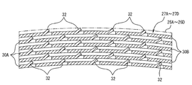
これら磁気作業体ユニット27A~27Dのそれぞれは、図3及び図4に示すように、磁気熱量効果を発揮する磁気作業物質で形成された2種類の第1磁気作業体30A及び第2磁気作業体30Bを複数枚半径方向に積層して構成されている。
ここで、第1磁気作業体30Aは、図4(a)に示すように、磁気作業物質の粉末原料を例えば溶融急冷法よって例えば厚さ1ミリで中空ダクト26A~26Dと同じ円弧状断面及び円周長を有する板状体31を形成する。このとき、板状体31の切り起こし片を形成する位置に切り起こし溝を形成しておくことが好ましいが、板状体31を形成した後に切り起こし溝を形成するようにしても良い。
ここで、第1磁気作業体30Aは、図4(a)に示すように、磁気作業物質の粉末原料を例えば溶融急冷法よって例えば厚さ1ミリで中空ダクト26A~26Dと同じ円弧状断面及び円周長を有する板状体31を形成する。このとき、板状体31の切り起こし片を形成する位置に切り起こし溝を形成しておくことが好ましいが、板状体31を形成した後に切り起こし溝を形成するようにしても良い。
そして、板状体31をプレス機でプレス加工することにより、円周方向に切り起こして隙間形成変形部となる複数の切り起こし片32を形成する。ここで、切り起こし片32は、積層したときに支える板状体31に撓みが生じることがないように長さ方向X及び幅方向Yにそれぞれ所定間隔を保って複数例えば3個以上形成する。そして、切り起こし片32の切り起こし方向は全て同じ方向とし、長さ及び角度は、積層時に熱媒体通路を形成するために必要する隙間に合わせて選定され、幅は支える板状体の荷重に合わせて選定される。
第1磁気作業体30Aの各きり起こし片32は、図4(a)に示すように、ダクト26A~26Dの円周方向すなわち幅方向Xに等間隔で、軸方向すなわち長さ方向Yに延長する複数の直線上に軸方向に等間隔で整列されて形成されている。
また、第2磁気作業体30Bは、図4(b)に示すように、第1磁気作業体30Aの切り起こし片32に対して平面視で重ならないように第1磁気作業体30Aの幅方向のきり起こし片32間の例えば中間位置に切り起こし片32を形成したことを除いては、第1磁気作業体30Aと同様の構成を有する。
なお、切り起こし片32の設置数は任意に設定することができ、板状体3の剛性が高い場合には、第1磁気作業体30A及び第2磁気作業体30Bに、それぞれ三点支持可能な少なくとも3個の切り起こし片32を第1磁気作業体30Aと第2磁気作業体30Bとで異なる位置に形成すればよい。
また、第2磁気作業体30Bは、図4(b)に示すように、第1磁気作業体30Aの切り起こし片32に対して平面視で重ならないように第1磁気作業体30Aの幅方向のきり起こし片32間の例えば中間位置に切り起こし片32を形成したことを除いては、第1磁気作業体30Aと同様の構成を有する。
なお、切り起こし片32の設置数は任意に設定することができ、板状体3の剛性が高い場合には、第1磁気作業体30A及び第2磁気作業体30Bに、それぞれ三点支持可能な少なくとも3個の切り起こし片32を第1磁気作業体30Aと第2磁気作業体30Bとで異なる位置に形成すればよい。
また、板状体31は、図4(a)及び(b)に示すように、長手方向に高い磁気熱量効果を発揮する温度帯が異なる複数例えば第1磁気作業物質MM1、第2磁気作業物質MM2及び第3磁気作業物質MM3の3つの磁気作業物質を例えば温度帯が順に高くなるように配列して構成することが好ましい。一例として、3つの磁気作業物質MM1~MM3として、温度Tとエントロピー変化(-ΔS)〔J/kg・K〕との関係が、図5に表されるものが選択されている。
すなわち、第1磁気作業物質MM1は図5の特性曲線L1で示すように、一番低いキュリー点付近の温度Tp1でエントロピー変化(-ΔS)がピークとなる山形特性を有し、第2磁気作業物質MM2は、図5の特性曲線L2で示すように、第1磁気作業物質MM1より高いキュリー点付近の温度Tp2でエントロピー変化(-ΔS)がピークとなる山形特性を有し、第3磁気作業物質MM3は、第2磁気作業物質MM2より高いキュリー点付近の温度Tp3でエントロピー変化(-ΔS)がピークとなる山形特性を有するMn系材料又はLa系材料が使用されている。
これらMn系材料又はLa系材料は、従来使用されていたGd系材料よりも励磁/消磁による磁気エントロピー変化(-ΔS)が大きく、吸熱/放熱能力も高い。しかしながら、各材料の高い磁気熱量効果を発揮する稼働温度域(駆動温度スパン)がGd系材料よりも狭いため、単体で使用したのでは常温から必要とする冷凍/放熱(給湯等)温度まで温度変化をさせることができない。
このため、第1磁気作業物質MM1、第2磁気作業物質MM2及び第3磁気作業物質MM3を板状体31の長手方向に並べて配置することにより、必要な温度範囲で高い磁気熱量効果を得ることができる。
このため、第1磁気作業物質MM1、第2磁気作業物質MM2及び第3磁気作業物質MM3を板状体31の長手方向に並べて配置することにより、必要な温度範囲で高い磁気熱量効果を得ることができる。
そして、図3に示すように、中空ダクト26A~26D内に、第1磁気状作業体30A及び第2磁気作業体30Bを交互に半径方向に積層することにより、磁気作業体ユニット27A~27Dを構成する。このとき、各磁気作業体30A及び30Bの切り起こし片32の幅方向に例えば水でなる熱媒体を通過させることにより、切り起こし片32が熱媒体の通過に妨げとなることがなく、流路抵抗を小さくして、熱媒体を円滑に通過させることができる。
なお、磁気作業体ユニット27A~27Dは、第1磁気作業体30A及び第2磁気作業体30Bを積層したままでもよいが、各磁気作業体30A及び30Bを確実に固定する場合には、中空ダクト26A~26Dの円弧状側面部26c及び26dに対向する円周方向の側面に接合板をロウ付け等の接合手段で接合する。
そして、図1に示すように、上記構成を有するヒートポンプ本体11の中空ダクト26Aの高温端28に高温配管PH11,PH12が接続され、中空ダクト26Aと軸対称位置となる中空ダクト26Bの高温端28に高温配管PH21,PH22が接続される。中空ダクト26Cの高温端28に高温配管PH31,PH32が接続され、中空ダクト26Cと軸対称位置となる中空ダクト26Dの高温端28に高温配管PH41,PH42が接続される。
そして、図1に示すように、上記構成を有するヒートポンプ本体11の中空ダクト26Aの高温端28に高温配管PH11,PH12が接続され、中空ダクト26Aと軸対称位置となる中空ダクト26Bの高温端28に高温配管PH21,PH22が接続される。中空ダクト26Cの高温端28に高温配管PH31,PH32が接続され、中空ダクト26Cと軸対称位置となる中空ダクト26Dの高温端28に高温配管PH41,PH42が接続される。
同様に、中空ダクト26Aの低温端29に低温配管PL11,PL12が接続され、中空ダクト26Aの軸対称位置となる中空ダクト26Bの低温端29に低温配管PL21,PL22が接続される。中空ダクト26Cの低温端29に低温配管PL31,PL32が接続され、中空ダクト26Cの軸対称位置となる中空ダクト26Dの低温端29に低温配管PL41,PL42が接続される。
高温側切換弁12は、例えばロータリ弁、電磁弁、ポペット弁等で構成され、ロータ21の回転に伴って切換制御される。この高温側切換弁12は、中空ダクト26A~26Dと接続される接続ポート12A及び12Bと、放熱側熱交換器13の入口に接続される流出ポート12Cと、循環ポンプ15の吐出側に接続される流入ポート12Dとを備えている。そして、高温側切換弁12は、前述したロータ21の回転に同期して接続ポート12Aを流出ポート12Cに連通し、且つ、接続ポート12Bを流入ポート12Dに連通する状態と、接続ポート12Aを流入ポート12Dに連通し、且つ、接続ポート12Bを流出ポート12Cに連通する状態とに切り換えられる。
高温側切換弁12は、例えばロータリ弁、電磁弁、ポペット弁等で構成され、ロータ21の回転に伴って切換制御される。この高温側切換弁12は、中空ダクト26A~26Dと接続される接続ポート12A及び12Bと、放熱側熱交換器13の入口に接続される流出ポート12Cと、循環ポンプ15の吐出側に接続される流入ポート12Dとを備えている。そして、高温側切換弁12は、前述したロータ21の回転に同期して接続ポート12Aを流出ポート12Cに連通し、且つ、接続ポート12Bを流入ポート12Dに連通する状態と、接続ポート12Aを流入ポート12Dに連通し、且つ、接続ポート12Bを流出ポート12Cに連通する状態とに切り換えられる。
接続ポート12Aには、ヒートポンプ本体11から引き出された各高温配管PH11~PH41が接続され、接続ポート12Bには、ヒートポンプ本体11から引き出された高温配管PH12~PH42が接続されている。
高温側切換弁12の流出ポート12Cは、配管41を介して放熱側熱交換器13の入口に接続され、この放熱側熱交換器13の出口は配管42、この配管42の途中に配置されたヒータ14を介して循環ポンプ15の吸込側に接続されている。そして、この循環ポンプ15の吐出側が配管43を介して高温側切換弁12の流入ポート12Dに接続されて排熱側の循環経路が構成されている。
高温側切換弁12の流出ポート12Cは、配管41を介して放熱側熱交換器13の入口に接続され、この放熱側熱交換器13の出口は配管42、この配管42の途中に配置されたヒータ14を介して循環ポンプ15の吸込側に接続されている。そして、この循環ポンプ15の吐出側が配管43を介して高温側切換弁12の流入ポート12Dに接続されて排熱側の循環経路が構成されている。
低温側切換弁16は、前述した高温側切換弁12と同様に、例えばロータリ弁、電磁弁、ポペット弁等で構成され、ロータ21の回転に伴って切換制御される。この低温側切換弁16は、中空ダクト26A~26Dと接続される接続ポート16A及び16Bと、吸熱側熱交換器17と接続される流出ポート16C及び流入ポート16Dとを備えている。
接続ポート16Aには、ヒートポンプ本体11から引き出された各低温配管PL11~PL41が接続され、接続ポート16Bには、ヒートポンプ本体11から引き出された低温配管PL12~PL42が接続されている。また、流出ポート16Cは配管44を介して吸熱側熱交換器17の入口に接続され、流入ポート16Dは配管45を介して吸熱側熱交換器17の出口に接続され、吸熱側の循環経路が構成されている。
接続ポート16Aには、ヒートポンプ本体11から引き出された各低温配管PL11~PL41が接続され、接続ポート16Bには、ヒートポンプ本体11から引き出された低温配管PL12~PL42が接続されている。また、流出ポート16Cは配管44を介して吸熱側熱交換器17の入口に接続され、流入ポート16Dは配管45を介して吸熱側熱交換器17の出口に接続され、吸熱側の循環経路が構成されている。
そして、低温側切換弁16は、前述したロータ21の回転に同期して接続ポート16Aを流出ポート16Cに連通し、且つ、接続ポート16Bを流入ポート16Dに連通する状態と、接続ポート16Aを流入ポート16Dに連通し、且つ、接続ポート16Bを流出ポート16C連通する状態とに切り換えられる。
これら循環ポンプ15、高温側切換弁12、低温側切換弁16や各配管により、各磁気作業体ユニット27A~27Dの高温端28と低温端29の間で熱媒体を往復移動させる熱媒体移動機構が構成される。
これら循環ポンプ15、高温側切換弁12、低温側切換弁16や各配管により、各磁気作業体ユニット27A~27Dの高温端28と低温端29の間で熱媒体を往復移動させる熱媒体移動機構が構成される。
[磁気ヒートポンプ装置10の動作]
次に上記構成を有する磁気ヒートポンプ装置10の動作について説明する。
先ず、ヒートポンプ本体11のロータ21が0°の位置(図2に示す位置)にあるとき、永久磁石25A及び25Bが0°及び180°の位置にあるので、この0°及び180°の位置にある磁気作業体ユニット27A、27Bに印加される磁場の大きさは増大し、励磁されて温度が上昇する。
一方、これと90°位相が異なる90°及び270°の位置にある磁気作業体ユニット27C、27Dに印加される磁場の大きさは減少し、消磁されて温度が低下する。
また、ロータ21が0°の位置(図2)にあるとき、高温側切換弁12は接続ポート12Aを流出ポート12Cに連通し、且つ、接続ポート12Bを流入ポート12Dに連通する状態とし、低温側切換弁16は接続ポート16Aを流入ポート16Dに連通し、且つ、接続ポート16Bを流出ポート16Cに連通する状態とする。
次に上記構成を有する磁気ヒートポンプ装置10の動作について説明する。
先ず、ヒートポンプ本体11のロータ21が0°の位置(図2に示す位置)にあるとき、永久磁石25A及び25Bが0°及び180°の位置にあるので、この0°及び180°の位置にある磁気作業体ユニット27A、27Bに印加される磁場の大きさは増大し、励磁されて温度が上昇する。
一方、これと90°位相が異なる90°及び270°の位置にある磁気作業体ユニット27C、27Dに印加される磁場の大きさは減少し、消磁されて温度が低下する。
また、ロータ21が0°の位置(図2)にあるとき、高温側切換弁12は接続ポート12Aを流出ポート12Cに連通し、且つ、接続ポート12Bを流入ポート12Dに連通する状態とし、低温側切換弁16は接続ポート16Aを流入ポート16Dに連通し、且つ、接続ポート16Bを流出ポート16Cに連通する状態とする。
そして、循環ポンプ15の運転により、熱媒体(水)は図1に実線矢印で示すように、循環ポンプ15→配管43→高温側切換弁12の流入ポート12Dから接続ポート12B→高温配管PH32及びPH42→90°及び270°の位置の磁気作業体ユニット27B及び27D→低温配管PL32及びPL42→低温側切換弁16の接続ポート16Bから流出ポート16C→配管44→吸熱側熱交換器17→配管45→低温側切換弁16の流入ポート16Dから接続ポート16A→低温配管PL11及びPL21→0°及び180°の位置の磁気作業体ユニット27A及び27B→高温配管PH11及びPH21→高温側切換弁12の接続ポート12Aから流出ポート12C→配管41→放熱側熱交換器13→配管42→ヒータ14→循環ポンプ15の順で循環される状態となる。
磁気作業体ユニット27A、27B中の熱媒体(水)は磁気作業体ユニット27A、27Bの軸方向に振動し、熱を低温端29から高温端28へ伝達し、高温端28で高温となった熱媒体(水)が高温配管から放熱側熱交換器13に流出し、仕事分の熱量を外部(外気等)に放出し、低温端29で低温となった熱媒体(水)が低温配管から吸熱側熱交換器17に流出し、被冷却体46から吸熱し、被冷却体46を冷却する。
すなわち、消磁されて温度が低下した磁気作業体ユニット27C、27Dに放熱し、冷却された熱媒体(水)は、吸熱側熱交換器17で被冷却体46から吸熱し、この被冷却体46を冷却した後、熱媒体(水)は、励磁されて温度が上昇した磁気作業体ユニット27A、27Bから吸熱してそれを冷却し、放熱側熱交換器13に戻り、仕事分の熱量を外部(外気等)に放出する。
すなわち、消磁されて温度が低下した磁気作業体ユニット27C、27Dに放熱し、冷却された熱媒体(水)は、吸熱側熱交換器17で被冷却体46から吸熱し、この被冷却体46を冷却した後、熱媒体(水)は、励磁されて温度が上昇した磁気作業体ユニット27A、27Bから吸熱してそれを冷却し、放熱側熱交換器13に戻り、仕事分の熱量を外部(外気等)に放出する。
次に、ロータ21を永久磁石25A、25Bとともに90°回転させると、0°と180°との位置にある磁気作業体ユニット27A、27Bは消磁されて温度が低下し、90°及び270°の位置にある磁気作業体ユニット27C、27Dは、励磁されて温度が上昇する。このとき、高温側切換弁12がロータリ弁で構成される場合、ロータ21と共にその弁体が90°回転されるため、今度は熱媒体(水)が図1に点線矢印で示すように、循環ポンプ15→配管43→高温側切換弁12の流入ポート12Dから接続ポート12B→高温配管PH12及びPH22→0°及び180°の位置の磁気作業体ユニット27A及び27B→低温配管PL12及びPL22→低温側切換弁16の接続ポート16Bから流出ポート16C→配管44→吸熱側熱交換器17→配管45→低温側切換弁16の流入ポート16Dから接続ポート16A→低温配管PL31及びPL41→90°及び270°の位置の磁気作業体ユニット27C及び27D→高温配管PH31及びPH41→高温側切換弁12の接続ポート12Aから流出ポート12C→配管41→放熱側熱交換器13→配管42→ヒータ14→循環ポンプ15の順で循環される状態となる。
このロータ21の回転と高温側切換弁12及び低温側切換弁16の切り換えを比較的高速の回転数とタイミングで行い、各磁気作業体ユニット27A~27Dの高温端28と低温端29の間で熱媒体(水)を往復移動させ、励磁/消磁される各磁気作業体ユニット27A~27Dからの吸熱/放熱を繰り返すことによって、各磁気作業体ユニット27A~27Dの高温端28と低温端29の温度差が徐々に拡大し、やがて吸熱側熱交換器17に繋がる各磁気作業体ユニット27A~27Dの低温端29の温度は磁気作業体ユニット27A~27Dの冷凍能力と被冷却体46の熱負荷とがバランスする温度まで低下し、放熱側熱交換器13に繋がる各磁気作業体ユニット27A~27Dの高温端28の温度は放熱側熱交換器13の放熱能力と冷凍能力とがバランスして略一定温度になる。
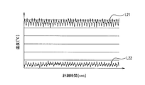
上述した如く吸熱/放熱の繰り返しにより、各磁気作業体ユニット27A~27Dの高温端28と低温端29の温度差は広がり、磁気作業物質の能力に釣り合った温度差になった時点で温度変化は飽和することになる。ここで、図5はこのように温度変化が飽和した状態における高温端28と低温端29の温度をL21とL22で示している。この図からも明らかなように高温端28、低温端29共に励磁と消磁による吸熱と放熱の影響を受け、所定の温度幅(実施例では2K程)をもって上下する。
このような小さい温度差で外部(外気や被冷却体46)と熱交換することができるように、実施例では放熱側熱交換器13と吸熱側熱交換器17の双方、又は、何れか一方をマイクロチャンネル型の熱交換器で構成している。マイクロチャンネル型の熱交換器は他の形式の熱交換器と比較して伝熱係数が高い上、単位体積当たりの伝熱面積も広いので、本発明のような磁気ヒートポンプ装置10により所要の能力を得る上で極めて好適である。
そして、磁気作業体ユニット27A~27Dの高温端28又は低温端29に供給される熱媒体は、積層された磁気作業体30A及び30B間の隙間で形成される熱媒体通路を通って高温端28から低温端29側へ又は低温端29から高温端28側へ流れる。このとき、隙間で構成される熱媒体通路は軸方向に直線状に形成されているので、流路抵抗が少なく、圧力損失も少なくなる。
そして、磁気作業体ユニット27A~27Dの高温端28又は低温端29に供給される熱媒体は、積層された磁気作業体30A及び30B間の隙間で形成される熱媒体通路を通って高温端28から低温端29側へ又は低温端29から高温端28側へ流れる。このとき、隙間で構成される熱媒体通路は軸方向に直線状に形成されているので、流路抵抗が少なく、圧力損失も少なくなる。
このとき、各磁気作業体30A及び30Bの切り起こし片32の切り起こし方向が円周方向であって、幅方向が熱媒体の通流方向に沿っているので、切り起こし片32が熱媒体の通流に邪魔となることがない。しかも、切り起こし片32によって、切り起こし片32を設けない場合に比較して熱媒体との伝熱面積を拡大することができる。このため、磁気作業体ユニット27A~27Dと熱媒体との間で良好な熱交換を行うことができる。
さらに、各磁気作業体30A及び30Bのきり起こし片32が長さ方向すなわち熱媒体の通流方向に整列されているので、流路断面積にバラツキが生じることがない。
さらに、各磁気作業体30A及び30Bのきり起こし片32が長さ方向すなわち熱媒体の通流方向に整列されているので、流路断面積にバラツキが生じることがない。
また、磁気作業体30A及び30Bを形成する場合に、切削、研削、研磨等の機械加工を必要としないので、切り屑が殆ど発生することがなく、高価な磁気作業物質を有効に使用することができる。
また、磁気作業体ユニット27A~27Dの各磁気作業体30A及び30B間の隙間を調整するには、切り起こし片32の長さ及び切り起こし角度を調整することにより、隙間を任意に調整することができる。
また、磁気作業体ユニット27A~27Dの各磁気作業体30A及び30B間の隙間を調整するには、切り起こし片32の長さ及び切り起こし角度を調整することにより、隙間を任意に調整することができる。
このように、上記第1の実施形態によると、磁気作業体30A及び30Bに切り起こし片32を形成したので、磁気作業体30A及び30Bを交互に積層するだけで、所定隙間の熱媒体流路を形成することができ、磁気作業体ユニット27A~27Dを容易に且つ低コストで製作することができる。
したがって、この磁気作業体ユニット27A~27Dを組込んだヒートポンプ本体11を容易に低コストで製作することができ、延いては磁気ヒートポンプ装置10全体を容易に低コストで製作することができる。
したがって、この磁気作業体ユニット27A~27Dを組込んだヒートポンプ本体11を容易に低コストで製作することができ、延いては磁気ヒートポンプ装置10全体を容易に低コストで製作することができる。
なお、上記第1の実施形態では、隙間調整変形部を切り起こし片32で構成する場合について説明したが、これに限定されるものではなく、図7に示すように、板状体31にプレス加工によって、円周方向に複数の折り曲げ部33を熱媒体の通流方向に沿って形成し、この折り曲げ部33を隙間調整変形部とするようにしてもよい。この場合に、折り曲げ部33は、図7に示すように、逆V字状に形成する場合に限らず、円弧状に形成したり、角形に形成したりすることができ、要は、隙間調整が可能なように板状体31の板面から突出していればよい。
また、上記第1の実施形態では、2種類の磁気作業体30A及び30Bを使用した場合について説明したが、これに限定されるものではなく、隙間調整変形部を異なる位置に形成した3種類以上の磁気作業体を使用することもできる。さらには、幅方向又は長さ方向の両端部において、一方の端部の隙間調整変形部の形成開始位置と、他方の端部の隙間調整変形部の形成開始位置とを異ならすことにより、1種類の磁気作業体を平面から見て順次180度回転させながら積層することで磁気作業体ユニットを構成することができる。
また、隙間調整変形部の数は、磁気作業体を支持できれば3個でもよく、4つ以上でもよい。
また、隙間調整変形部の数は、磁気作業体を支持できれば3個でもよく、4つ以上でもよい。
[第2の実施形態]
次に、本発明に係る磁気作業体の第2の実施形態について図8及び図9を伴って説明する。
この第2の実施形態では、磁気作業体の伝熱面積をより拡大するようにしたものである。
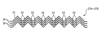
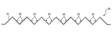
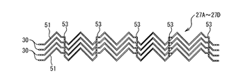
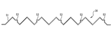
すなわち、第2の実施形態では、磁気作業体30を、図8及び図9に示すように、平板状の板状体31に代えて、三角波状に折り曲げた折り曲げ体51を積層して構成している。折り曲げ体51には、図9に示すように、傾斜面に切り起こし片52を互いに対向するように形成する。
そして、図8に示すように、磁気作業体30をそのまま積層することにより、切り起こし片52によって隣接する磁気作業体30を支えることができ、隙間を形成した磁気作業体ユニット27A~27Dを構成することができる。
次に、本発明に係る磁気作業体の第2の実施形態について図8及び図9を伴って説明する。
この第2の実施形態では、磁気作業体の伝熱面積をより拡大するようにしたものである。
すなわち、第2の実施形態では、磁気作業体30を、図8及び図9に示すように、平板状の板状体31に代えて、三角波状に折り曲げた折り曲げ体51を積層して構成している。折り曲げ体51には、図9に示すように、傾斜面に切り起こし片52を互いに対向するように形成する。
そして、図8に示すように、磁気作業体30をそのまま積層することにより、切り起こし片52によって隣接する磁気作業体30を支えることができ、隙間を形成した磁気作業体ユニット27A~27Dを構成することができる。
その他の構成については、前述した第1の実施形態と同様の構成を有し、対応部分には同一符号を付し、その詳細説明はこれを省略する。
この第2の実施形態によると、磁気作業体30を構成する板状体が折り曲げ体41で構成されているので、磁気作業体30の伝熱面積を前述した第1の実施形態に比較して広くすることができるとともに、磁気熱量効果も向上させることができる。
しかも、折り返し片52を折り曲げ体51の傾斜面に形成することにより、1種類の磁気作業体30を単に積層することにより、磁気作業体ユニットを構成することができる。したがって、磁気作業体ユニットをより低コストで製作することができる。
この第2の実施形態によると、磁気作業体30を構成する板状体が折り曲げ体41で構成されているので、磁気作業体30の伝熱面積を前述した第1の実施形態に比較して広くすることができるとともに、磁気熱量効果も向上させることができる。
しかも、折り返し片52を折り曲げ体51の傾斜面に形成することにより、1種類の磁気作業体30を単に積層することにより、磁気作業体ユニットを構成することができる。したがって、磁気作業体ユニットをより低コストで製作することができる。
なお、上記第2の実施形態でも、図10及び図11に示すように、折り曲げ体51の傾斜面に、隙間調整変形部となる切り起こし片52に代えてプレス加工による折り曲げ部53を形成するようにしてもよい。この場合には、折り曲げ部53の剛性が大きいので、全ての傾斜面に設けなくとも一つ置きの対向斜面に形成することができる。もちろん、全ての対向斜面に折り曲げ部53を設けるようにしてもよい。
また、上記第1及び第2の実施形態では、ステータ22に磁気作業体ユニット27A~27Dを配置した中空ダクト26A~26Dを設けた場合について説明したが、これに限定されるものではなく、磁気作業体を配置した中空ダクト数は任意数に設定することができるとともに、ロータ21に配置する永久磁石数も任意に設定することができる。要は励磁状態の磁気作業体と消磁状態の磁気作業体数が等しくなるようにすればよい。
また、上記第1及び第2の実施形態では、ステータ22に磁気作業体ユニット27A~27Dを配置した中空ダクト26A~26Dを設けた場合について説明したが、これに限定されるものではなく、磁気作業体を配置した中空ダクト数は任意数に設定することができるとともに、ロータ21に配置する永久磁石数も任意に設定することができる。要は励磁状態の磁気作業体と消磁状態の磁気作業体数が等しくなるようにすればよい。
また、上記第1及び第2の実施形態では、単体の磁気作業体となる板状体31が高い磁気熱量効果を発揮する温度帯が異なる3つの磁気作業物質で構成されている場合について説明したが、これに限定されるものではなく、4つ以上の磁気作業物質で構成するようにしてもよい。
また、上記第1及び第2の実施形態では、磁気ヒートポンプ装置をインナーロータ形に構成した場合について説明したが、これに限定されるものではなく、アウターロータ形に構成することもできる。
また、上記第1及び第2の実施形態では、磁気ヒートポンプ装置をインナーロータ形に構成した場合について説明したが、これに限定されるものではなく、アウターロータ形に構成することもできる。
さらには、ヒートポンプ本体を、図12に示すように構成することができる。すなわち、直方体形状に形成した磁気作業体70A及び70Bを、回転軸71を挟む円周上の90°及び270°の位置に固定し、これら磁気作業体70A~70Dを上下方向から挟むように回転軸71に固定された回転円板72A及び72Bを配置し、これら回転円板72A及び72Bの例えば回転軸71を挟む0°及び180°位置の対向面にそれぞれ一対の永久磁石73A及び73Bと74A及び74Bを配置する構成とするようにしてもよい。この場合、上下一対の永久磁石73A及び74Aと73B及び74Bとは、永久磁石73A及び74Aの磁気作業体と対向する面がN極(又はS極)とされ、永久磁石73B及び74Bの磁気作業体と対向する他方の面がS極(又はN極)とされて磁気作業体70A~70Dを上下方向に横切る磁束を発生させる。
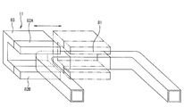
また、磁気ヒートポンプ装置として永久磁石を回転させる形式とする場合に限らず、図13に示すように、直方体形状に形成した磁気作業体81を固定配置し、この磁気作業体81に対して例えば上下方向に横切る磁束を発生させる永久磁石82A及び82Bを対向するように配置した直線移動体83を、永久磁石82A及び82Bが磁気作業体81に対向する位置と、磁気作業体81と対向しない位置との間で直線的に往復動させるようにした往復動型の磁気ヒートポンプ装置にも本発明を適用することができる。
10…磁気ヒートポンプ装置、11…ヒートポンプ本体、12…高温側切換弁、13…放熱側熱交換器、14…ヒータ、15…循環ポンプ、16…低温側切換弁、17…吸熱側熱交換器、21…ロータ、22…ステータ、23…回転軸、24…支持部材、25A,25B…永久磁石、26A~26D…中空ダクト、27A~27D…磁気作業体ユニット、30A…第1磁気作業体、30B…第2磁気作業体、31…板状体、32…切り起こし片、33…折り曲げ部、51…折り曲げ体、52…切り起こし片、53…折り曲げ部、70A~70D…磁気作業体、71…回転軸、72A,72B…回転円板、73A,73B,74A,74B…永久磁石、81…磁気作業体、82A,82B…永久磁石、83…直線移動体
Claims (9)
- 磁気作業物質で形成された板状体で構成され、該板状体に積層時に隙間調整部材となる隙間形成変形部を形成したことを特徴とする板状磁気作業体。
- 前記隙間形成変形部は、前記板状体の幅方向及び長さ方向にそれぞれ形成した複数の切り起こし片で構成され、前記切り起こし片は、前記板状体の熱媒体の通流方向に整列配置されていることを特徴とする請求項1に記載の板状磁気作業体。
- 前記隙間形成変形部は、前記板状体の少なくとも3個所に形成した切り起こし片で構成されていることを特徴とする請求項1に記載の板状磁気作業体。
- 前記隙間形成変形部は、前記板状体の少なくとも対向辺に沿って形成された折り曲げ部で構成されていることを特徴とする請求項1に記載の板状磁気作業体。
- 前記折り曲げ部は、熱媒体の流路に沿って形成されていることを特徴とする請求項4に記載の板状磁気作業体。
- 前記板状体は、高い磁気熱量効果を発揮する温度帯が異なる複数の磁気作業物質を前記温度帯が順に高くなるように一方向に配列して構成されていることを特徴とする請求項1から5の何れか一項に記載の板状磁気作業体。
- 前記磁気作業物質は、Mn系材料及びLa系材料の何れかであることを特徴とする請求項1から6の何れか一項に記載の板状磁気作業体。
- 前記板状体は、折り曲げ体で構成されていることを特徴とする請求項1から7の何れか一項に記載の板状磁気作業体。
- 熱媒体が通流される容器内に請求項1から8の何れか一項に記載の板状磁気作業体を前記隙間形成変形部で形成される隙間を保って複数積層した磁気作業体ユニットと、
該磁気作業体ユニットの磁気作業体に印加される磁場の大きさを変更する磁場変更機構と、
前記磁気作業体ユニットの高温端及び低温端間で前記熱媒体を移動させる熱媒体移動機構と、
前記高温端側の前記熱媒体を放熱させる放熱側熱交換器と、
前記低温端側の前記熱媒体に吸熱させる吸熱側熱交換器と
を備えたことを特徴とする磁気ヒートポンプ装置。
Priority Applications (3)
| Application Number | Priority Date | Filing Date | Title |
|---|---|---|---|
| CN201880017924.9A CN110402357A (zh) | 2017-03-13 | 2018-02-13 | 板状磁工作件以及使用该板状磁工作件的磁热泵装置 |
| DE112018001297.2T DE112018001297T5 (de) | 2017-03-13 | 2018-02-13 | Plattenförmiger magnetischer werkkörper und eine diesen verwendende magnetische wärmepumpenvorrichtung |
| US16/494,164 US20200018525A1 (en) | 2017-03-13 | 2018-02-13 | Plate-shaped magnetic work body and magnetic heat pump device using same |
Applications Claiming Priority (2)
| Application Number | Priority Date | Filing Date | Title |
|---|---|---|---|
| JP2017047423A JP2018151120A (ja) | 2017-03-13 | 2017-03-13 | 板状磁気作業体及びこれを使用した磁気ヒートポンプ装置 |
| JP2017-047423 | 2017-03-13 |
Publications (1)
| Publication Number | Publication Date |
|---|---|
| WO2018168296A1 true WO2018168296A1 (ja) | 2018-09-20 |
Family
ID=63522141
Family Applications (1)
| Application Number | Title | Priority Date | Filing Date |
|---|---|---|---|
| PCT/JP2018/004814 Ceased WO2018168296A1 (ja) | 2017-03-13 | 2018-02-13 | 板状磁気作業体及びこれを使用した磁気ヒートポンプ装置 |
Country Status (5)
| Country | Link |
|---|---|
| US (1) | US20200018525A1 (ja) |
| JP (1) | JP2018151120A (ja) |
| CN (1) | CN110402357A (ja) |
| DE (1) | DE112018001297T5 (ja) |
| WO (1) | WO2018168296A1 (ja) |
Cited By (1)
| Publication number | Priority date | Publication date | Assignee | Title |
|---|---|---|---|---|
| US20220268494A1 (en) * | 2019-07-25 | 2022-08-25 | National Institute For Materials Science | Magnetic refrigeration module, magnetic refrigeration system, and cooling method |
Families Citing this family (1)
| Publication number | Priority date | Publication date | Assignee | Title |
|---|---|---|---|---|
| JP7670958B2 (ja) * | 2021-03-30 | 2025-05-01 | ダイキン工業株式会社 | 固体冷媒による冷凍モジュールのベッド構造 |
Citations (3)
| Publication number | Priority date | Publication date | Assignee | Title |
|---|---|---|---|---|
| JP2012255642A (ja) * | 2011-05-13 | 2012-12-27 | Denso Corp | 熱磁気サイクル装置 |
| US20130283822A1 (en) * | 2010-11-05 | 2013-10-31 | Jun Shen | Magnetic refrigerant bed and method for manufacturing the same |
| JP2016145655A (ja) * | 2015-02-06 | 2016-08-12 | 株式会社フジクラ | 熱交換器及び磁気ヒートポンプ装置 |
Family Cites Families (3)
| Publication number | Priority date | Publication date | Assignee | Title |
|---|---|---|---|---|
| CN102607215B (zh) * | 2012-03-23 | 2014-07-23 | 中南大学 | 热声回热器 |
| FR2994252B1 (fr) * | 2012-08-01 | 2014-08-08 | Cooltech Applications | Piece monobloc comprenant un materiau magnetocalorique ne comprenant pas un alliage comprenant du fer et du silicium et un lanthanide, et generateur thermique comprenant ladite piece |
| JP5853907B2 (ja) * | 2012-08-27 | 2016-02-09 | 株式会社デンソー | 磁気冷凍材料熱交換器の製造方法 |
-
2017
- 2017-03-13 JP JP2017047423A patent/JP2018151120A/ja active Pending
-
2018
- 2018-02-13 WO PCT/JP2018/004814 patent/WO2018168296A1/ja not_active Ceased
- 2018-02-13 CN CN201880017924.9A patent/CN110402357A/zh not_active Withdrawn
- 2018-02-13 DE DE112018001297.2T patent/DE112018001297T5/de not_active Ceased
- 2018-02-13 US US16/494,164 patent/US20200018525A1/en not_active Abandoned
Patent Citations (3)
| Publication number | Priority date | Publication date | Assignee | Title |
|---|---|---|---|---|
| US20130283822A1 (en) * | 2010-11-05 | 2013-10-31 | Jun Shen | Magnetic refrigerant bed and method for manufacturing the same |
| JP2012255642A (ja) * | 2011-05-13 | 2012-12-27 | Denso Corp | 熱磁気サイクル装置 |
| JP2016145655A (ja) * | 2015-02-06 | 2016-08-12 | 株式会社フジクラ | 熱交換器及び磁気ヒートポンプ装置 |
Cited By (1)
| Publication number | Priority date | Publication date | Assignee | Title |
|---|---|---|---|---|
| US20220268494A1 (en) * | 2019-07-25 | 2022-08-25 | National Institute For Materials Science | Magnetic refrigeration module, magnetic refrigeration system, and cooling method |
Also Published As
| Publication number | Publication date |
|---|---|
| CN110402357A (zh) | 2019-11-01 |
| US20200018525A1 (en) | 2020-01-16 |
| DE112018001297T5 (de) | 2020-01-02 |
| JP2018151120A (ja) | 2018-09-27 |
Similar Documents
| Publication | Publication Date | Title |
|---|---|---|
| CN110392810B (zh) | 磁工作件以及使用该磁工作件的磁热泵装置 | |
| EP2188577B1 (en) | A refrigeration device and a method of refrigerating | |
| CN108332444B (zh) | 用于主动再生磁热或电热热力发动机的多材料叶片 | |
| KR101357355B1 (ko) | 자기 열 발생기 | |
| CN103492819B (zh) | 磁制冷机 | |
| TWI425177B (zh) | 在使用磁熱材料的熱產生器中增加溫度梯度的方法和裝置 | |
| US20080314049A1 (en) | Active Magnetic Refrigerator | |
| CN103808061A (zh) | 磁制冷装置和磁制冷系统 | |
| CN115280082B (zh) | 使用固态制冷剂的冷却模块和使用固态制冷剂的冷却系统 | |
| WO2018168296A1 (ja) | 板状磁気作業体及びこれを使用した磁気ヒートポンプ装置 | |
| WO2012056577A1 (ja) | 熱交換器および磁気冷凍システム | |
| JP2017172820A (ja) | 熱磁気サイクル装置 | |
| WO2018168295A1 (ja) | 磁気作業体ユニット及びこれを使用した磁気ヒートポンプ装置 | |
| JP5724603B2 (ja) | 磁気冷凍システム及び該磁気冷凍システムを用いた空気調和装置 | |
| CN102317710A (zh) | 磁热热发生器 | |
| CN109952476A (zh) | 磁热泵装置 | |
| WO2022244773A1 (ja) | 熱電素子モジュール、及び熱電装置 | |
| WO2022158282A1 (ja) | エネルギー変換素子およびこれを用いた温度調節装置 | |
| JP7846344B2 (ja) | 固体冷媒による冷凍装置 | |
| JP2022154196A (ja) | 固体冷媒による冷凍モジュールのベッド構造 | |
| JP2016151393A (ja) | 熱交換器及び磁気ヒートポンプ装置 | |
| JP2016145655A (ja) | 熱交換器及び磁気ヒートポンプ装置 | |
| JP6683138B2 (ja) | 熱磁気サイクル装置 | |
| JP7030658B2 (ja) | 磁気冷凍機 | |
| JP2020008247A (ja) | 磁気熱量素子および熱磁気サイクル装置 |
Legal Events
| Date | Code | Title | Description |
|---|---|---|---|
| 121 | Ep: the epo has been informed by wipo that ep was designated in this application |
Ref document number: 18768684 Country of ref document: EP Kind code of ref document: A1 |
|
| 122 | Ep: pct application non-entry in european phase |
Ref document number: 18768684 Country of ref document: EP Kind code of ref document: A1 |