WO2018168166A1 - Optical module - Google Patents
Optical module Download PDFInfo
- Publication number
- WO2018168166A1 WO2018168166A1 PCT/JP2017/047285 JP2017047285W WO2018168166A1 WO 2018168166 A1 WO2018168166 A1 WO 2018168166A1 JP 2017047285 W JP2017047285 W JP 2017047285W WO 2018168166 A1 WO2018168166 A1 WO 2018168166A1
- Authority
- WO
- WIPO (PCT)
- Prior art keywords
- light
- mirrors
- condenser lens
- mirror
- optical module
- Prior art date
Links
Images


Classifications
-
- G—PHYSICS
- G02—OPTICS
- G02B—OPTICAL ELEMENTS, SYSTEMS OR APPARATUS
- G02B6/00—Light guides; Structural details of arrangements comprising light guides and other optical elements, e.g. couplings
- G02B6/24—Coupling light guides
- G02B6/42—Coupling light guides with opto-electronic elements
- G02B6/4201—Packages, e.g. shape, construction, internal or external details
- G02B6/4204—Packages, e.g. shape, construction, internal or external details the coupling comprising intermediate optical elements, e.g. lenses, holograms
- G02B6/4206—Optical features
-
- G—PHYSICS
- G02—OPTICS
- G02B—OPTICAL ELEMENTS, SYSTEMS OR APPARATUS
- G02B19/00—Condensers, e.g. light collectors or similar non-imaging optics
- G02B19/0004—Condensers, e.g. light collectors or similar non-imaging optics characterised by the optical means employed
- G02B19/0028—Condensers, e.g. light collectors or similar non-imaging optics characterised by the optical means employed refractive and reflective surfaces, e.g. non-imaging catadioptric systems
-
- G—PHYSICS
- G02—OPTICS
- G02B—OPTICAL ELEMENTS, SYSTEMS OR APPARATUS
- G02B19/00—Condensers, e.g. light collectors or similar non-imaging optics
- G02B19/0033—Condensers, e.g. light collectors or similar non-imaging optics characterised by the use
- G02B19/0047—Condensers, e.g. light collectors or similar non-imaging optics characterised by the use for use with a light source
- G02B19/0052—Condensers, e.g. light collectors or similar non-imaging optics characterised by the use for use with a light source the light source comprising a laser diode
- G02B19/0057—Condensers, e.g. light collectors or similar non-imaging optics characterised by the use for use with a light source the light source comprising a laser diode in the form of a laser diode array, e.g. laser diode bar
-
- G—PHYSICS
- G02—OPTICS
- G02B—OPTICAL ELEMENTS, SYSTEMS OR APPARATUS
- G02B27/00—Optical systems or apparatus not provided for by any of the groups G02B1/00 - G02B26/00, G02B30/00
- G02B27/09—Beam shaping, e.g. changing the cross-sectional area, not otherwise provided for
- G02B27/0905—Dividing and/or superposing multiple light beams
-
- G—PHYSICS
- G02—OPTICS
- G02B—OPTICAL ELEMENTS, SYSTEMS OR APPARATUS
- G02B6/00—Light guides; Structural details of arrangements comprising light guides and other optical elements, e.g. couplings
- G02B6/24—Coupling light guides
- G02B6/42—Coupling light guides with opto-electronic elements
- G02B6/4201—Packages, e.g. shape, construction, internal or external details
- G02B6/4204—Packages, e.g. shape, construction, internal or external details the coupling comprising intermediate optical elements, e.g. lenses, holograms
- G02B6/4214—Packages, e.g. shape, construction, internal or external details the coupling comprising intermediate optical elements, e.g. lenses, holograms the intermediate optical element having redirecting reflective means, e.g. mirrors, prisms for deflecting the radiation from horizontal to down- or upward direction toward a device
-
- H—ELECTRICITY
- H01—ELECTRIC ELEMENTS
- H01S—DEVICES USING THE PROCESS OF LIGHT AMPLIFICATION BY STIMULATED EMISSION OF RADIATION [LASER] TO AMPLIFY OR GENERATE LIGHT; DEVICES USING STIMULATED EMISSION OF ELECTROMAGNETIC RADIATION IN WAVE RANGES OTHER THAN OPTICAL
- H01S5/00—Semiconductor lasers
- H01S5/005—Optical components external to the laser cavity, specially adapted therefor, e.g. for homogenisation or merging of the beams or for manipulating laser pulses, e.g. pulse shaping
- H01S5/0071—Optical components external to the laser cavity, specially adapted therefor, e.g. for homogenisation or merging of the beams or for manipulating laser pulses, e.g. pulse shaping for beam steering, e.g. using a mirror outside the cavity to change the beam direction
-
- H—ELECTRICITY
- H01—ELECTRIC ELEMENTS
- H01S—DEVICES USING THE PROCESS OF LIGHT AMPLIFICATION BY STIMULATED EMISSION OF RADIATION [LASER] TO AMPLIFY OR GENERATE LIGHT; DEVICES USING STIMULATED EMISSION OF ELECTROMAGNETIC RADIATION IN WAVE RANGES OTHER THAN OPTICAL
- H01S5/00—Semiconductor lasers
- H01S5/02—Structural details or components not essential to laser action
- H01S5/022—Mountings; Housings
- H01S5/02208—Mountings; Housings characterised by the shape of the housings
-
- H—ELECTRICITY
- H01—ELECTRIC ELEMENTS
- H01S—DEVICES USING THE PROCESS OF LIGHT AMPLIFICATION BY STIMULATED EMISSION OF RADIATION [LASER] TO AMPLIFY OR GENERATE LIGHT; DEVICES USING STIMULATED EMISSION OF ELECTROMAGNETIC RADIATION IN WAVE RANGES OTHER THAN OPTICAL
- H01S5/00—Semiconductor lasers
- H01S5/02—Structural details or components not essential to laser action
- H01S5/022—Mountings; Housings
- H01S5/0225—Out-coupling of light
- H01S5/02251—Out-coupling of light using optical fibres
-
- H—ELECTRICITY
- H01—ELECTRIC ELEMENTS
- H01S—DEVICES USING THE PROCESS OF LIGHT AMPLIFICATION BY STIMULATED EMISSION OF RADIATION [LASER] TO AMPLIFY OR GENERATE LIGHT; DEVICES USING STIMULATED EMISSION OF ELECTROMAGNETIC RADIATION IN WAVE RANGES OTHER THAN OPTICAL
- H01S5/00—Semiconductor lasers
- H01S5/02—Structural details or components not essential to laser action
- H01S5/022—Mountings; Housings
- H01S5/023—Mount members, e.g. sub-mount members
- H01S5/02325—Mechanically integrated components on mount members or optical micro-benches
-
- H—ELECTRICITY
- H01—ELECTRIC ELEMENTS
- H01S—DEVICES USING THE PROCESS OF LIGHT AMPLIFICATION BY STIMULATED EMISSION OF RADIATION [LASER] TO AMPLIFY OR GENERATE LIGHT; DEVICES USING STIMULATED EMISSION OF ELECTROMAGNETIC RADIATION IN WAVE RANGES OTHER THAN OPTICAL
- H01S5/00—Semiconductor lasers
- H01S5/02—Structural details or components not essential to laser action
- H01S5/022—Mountings; Housings
- H01S5/0239—Combinations of electrical or optical elements
-
- H—ELECTRICITY
- H01—ELECTRIC ELEMENTS
- H01S—DEVICES USING THE PROCESS OF LIGHT AMPLIFICATION BY STIMULATED EMISSION OF RADIATION [LASER] TO AMPLIFY OR GENERATE LIGHT; DEVICES USING STIMULATED EMISSION OF ELECTROMAGNETIC RADIATION IN WAVE RANGES OTHER THAN OPTICAL
- H01S5/00—Semiconductor lasers
- H01S5/40—Arrangement of two or more semiconductor lasers, not provided for in groups H01S5/02 - H01S5/30
- H01S5/4012—Beam combining, e.g. by the use of fibres, gratings, polarisers, prisms
-
- G—PHYSICS
- G02—OPTICS
- G02B—OPTICAL ELEMENTS, SYSTEMS OR APPARATUS
- G02B27/00—Optical systems or apparatus not provided for by any of the groups G02B1/00 - G02B26/00, G02B30/00
- G02B27/09—Beam shaping, e.g. changing the cross-sectional area, not otherwise provided for
- G02B27/0916—Adapting the beam shape of a semiconductor light source such as a laser diode or an LED, e.g. for efficiently coupling into optical fibers
- G02B27/0922—Adapting the beam shape of a semiconductor light source such as a laser diode or an LED, e.g. for efficiently coupling into optical fibers the semiconductor light source comprising an array of light emitters
-
- G—PHYSICS
- G02—OPTICS
- G02B—OPTICAL ELEMENTS, SYSTEMS OR APPARATUS
- G02B27/00—Optical systems or apparatus not provided for by any of the groups G02B1/00 - G02B26/00, G02B30/00
- G02B27/09—Beam shaping, e.g. changing the cross-sectional area, not otherwise provided for
- G02B27/0938—Using specific optical elements
- G02B27/095—Refractive optical elements
- G02B27/0955—Lenses
-
- G—PHYSICS
- G02—OPTICS
- G02B—OPTICAL ELEMENTS, SYSTEMS OR APPARATUS
- G02B27/00—Optical systems or apparatus not provided for by any of the groups G02B1/00 - G02B26/00, G02B30/00
- G02B27/09—Beam shaping, e.g. changing the cross-sectional area, not otherwise provided for
- G02B27/0938—Using specific optical elements
- G02B27/0977—Reflective elements
-
- G—PHYSICS
- G02—OPTICS
- G02B—OPTICAL ELEMENTS, SYSTEMS OR APPARATUS
- G02B6/00—Light guides; Structural details of arrangements comprising light guides and other optical elements, e.g. couplings
- G02B6/24—Coupling light guides
- G02B6/42—Coupling light guides with opto-electronic elements
- G02B6/4201—Packages, e.g. shape, construction, internal or external details
- G02B6/4266—Thermal aspects, temperature control or temperature monitoring
- G02B6/4267—Reduction of thermal stress, e.g. by selecting thermal coefficient of materials
Definitions
- the present invention relates to an optical module.
- optical modules one in which light emitted from a laser diode is emitted through an optical fiber is known.
- an optical fiber is led out from the inside of the casing, and optical components such as a laser diode, a mirror, a lens, and an optical fiber are arranged in the casing.
- the light emitted from each laser diode is collected and then incident on the optical fiber, and is emitted from the optical fiber outside the housing.
- Patent Document 1 a plurality of laser diodes arranged on a step-shaped mount, mirrors provided corresponding to the respective laser diodes, and light reflected by the respective mirrors are collected.
- An optical module including a condensing lens that is incident on an optical fiber is disclosed.
- Patent Document 2 a plurality of laser diodes arranged on the same plane, a collimator device that collimates light emitted from each laser diode, a diffraction grating that changes the direction of the collimated light,
- An optical module includes a condensing lens that condenses the light whose direction is changed by each diffraction grating and makes the light incident on an optical fiber.
- the laser diode provided in such an optical module is formed by stacking semiconductor layers in a direction perpendicular to the surface on which the laser diode is arranged. Therefore, the light emitted from this laser diode is set to the slow axis direction in the direction parallel to the surface on which the plurality of laser diodes are arranged.
- the heat generated by the laser diode is transmitted to the heat sink via the mount.
- a difference occurs in the length of the heat dissipation path between the laser diodes. For this reason, it becomes easy to produce the difference in the junction temperature of each laser diode.
- a difference occurs in the junction temperature of each laser diode, there is a concern that a difference occurs in the lifetime of each laser diode, and the reliability design of the optical module becomes complicated.
- the light emitted from the plurality of laser diodes is arranged in the slow axis direction as described above.
- the light emitted from the laser diode is less likely to be collimated in the slow axis direction than the fast axis.
- an object of the present invention is to provide an optical module capable of emitting light with high output while suppressing the complexity of reliability design.
- the optical module of the present invention includes a plurality of light emitting elements arranged on the same plane, and a plurality of mirrors that reflect the respective lights emitted from the respective light emitting elements, and the plurality of mirrors are respectively The light emitted from the light emitting element is reflected in a direction inclined with respect to the plane and aligned in the fast axis direction.
- the optical module by arranging the respective light emitting elements on the same plane, it becomes easy to align the lengths of the heat radiation paths of the heat emitted from the respective light emitting elements. For this reason, the said optical module suppresses that a difference arises in the junction temperature of each light emitting element, and the complexity of reliability design can be suppressed.
- the light emitted from the plurality of light emitting elements is arranged in the fast axis direction by reflection, so that the light emitted from the plurality of light emitting elements can be collected spatially densely. For this reason, the optical module can emit light with high output.
- an angle ⁇ between the direction in which each light emitted from each light emitting element is incident on each mirror and the direction in which each light is reflected and emitted from each mirror is greater than 0 ° and smaller than 90 °. Is preferred.
- each light emitted from each light emitting element is reflected at a predetermined angle, so that the light emitted from the plurality of light emitting elements can be easily arranged in the fast axis direction by reflection.
- the light reflected by at least one of the mirrors overlaps with at least one other mirror in the fast axis direction.
- the reflected light reflected by the mirror is propagated so as to overlap with other mirrors, so that the optical module can be miniaturized by narrowing the distance between the light emitting element and the mirror.
- the light reflected by each of the mirrors is reflected in a direction in which the plurality of mirrors are juxtaposed when viewed from the fast axis direction of the light incident on each of the mirrors.
- each light reflected by each mirror can suppress the deviation of the respective lights reflected by the respective mirrors in the slow axis direction. For this reason, each light reflected by each mirror can be condensed in a narrow region.
- the plurality of mirrors reflect the respective light emitted from the respective light emitting elements so that the propagation directions thereof are parallel to each other.
- each light emitted from each light emitting element is reflected by the plurality of mirrors so as to approach each other in the fast axis direction, It is also preferable that the light is condensed at one point by the condensing lens.
- it further includes a condensing lens on which the light reflected by the plurality of mirrors is incident, and each light emitted from each of the light emitting elements is reflected away from each other in the fast axis direction by the plurality of mirrors. It is also preferable that the light is condensed at one point by the condenser lens.
- the incident angle of the light incident on the outer peripheral side of the condenser lens that is, the position away from the optical axis of the condenser lens is increased. can do.
- the aberration of the light collected by the condenser lens can be reduced.
- the light refracting member may further include a condenser lens on which light reflected by the plurality of mirrors is incident, and a light refracting member disposed between the plurality of mirrors and the condenser lens. It is preferable that light is refracted so that the propagation direction of each light reflected by the plurality of mirrors approaches parallel to the optical axis of the condenser lens.
- the optical system further includes a condensing lens on which the light reflected by the plurality of mirrors is incident, and the condensing lens includes the incident direction of the light at the center of the region where the light reflected by the plurality of mirrors is incident and the collection It is also preferable that the optical axes of the optical lenses are arranged so as to be parallel to each other.
- the optical fiber further includes an optical fiber on which light reflected by the plurality of mirrors is incident, and the end surface on the light incident side of the optical fiber has a propagation direction of the light incident on the optical fiber. It is preferable to have an inclined surface that refracts light so as to approach a direction parallel to the axis.
- the propagation direction of the light propagating through the core of the optical fiber can be made to be a direction nearly parallel to the optical axis of the optical fiber. Leakage from the core can be suppressed.
- the mirror has a fixed surface fixed to another member, and the fixed surface is parallel to a surface of the other member to which the mirror is fixed.
- the adhesive for fixing the fixed surface of the mirror and other members can be made to have a uniform thickness. For this reason, when the volume of the adhesive changes due to a change in temperature, humidity, or the like, it is possible to suppress the reflection surface of the mirror from being inclined, and it is possible to suppress a change in the direction of light reflection by the mirror.
- FIG. 1 is a perspective view showing an optical module according to a first embodiment of the present invention. It is the figure which removed the cover body of the optical module shown in FIG.
- FIG. 3 is a cross-sectional view of the optical module taken along line III-III shown in FIG. It is a top view which shows the optical path of the light reflected by the mirror shown in FIG. It is a side view which shows the optical path of the light reflected by the mirror shown in FIG. It is a figure which shows the breadth of the light which injects into the entrance plane of the condensing lens shown in FIG. It is a figure which shows the optical module which concerns on 2nd Embodiment of this invention from the viewpoint similar to FIG.
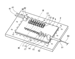
- FIG. 1 is a perspective view showing an optical module according to this embodiment.
- the optical module 1 according to the present embodiment supplies power to a housing composed of a base plate 2 and a lid 3, optical components to be described later fixed in the housing, and some optical components. And a connector 41.
- FIG. 2 is a view in which the lid 3 of the optical module 1 shown in FIG. 1 is removed.
- the optical path of the light emitted from the laser diode 11 is indicated by a broken line.
- FIG. 3 is a cross-sectional view of the optical module 1 taken along line III-III shown in FIG.
- the base plate 2 is a plate having a flat bottom surface serving as a bottom plate of the housing.
- the base plate 2 is a flat plate member as shown in FIGS.
- the base plate 2 is made of metal, and examples of the metal constituting the base plate 2 include copper and stainless steel.
- a plurality of screw holes 27 are formed in the outer peripheral portion of the base plate 2.
- the submount 4 is fixed on the base plate 2 by solder 7.
- the submount 4 is a flat substrate and is made of a material having a smaller linear expansion coefficient than that of the base plate 2.
- the base plate 2 is made of copper
- the submount 4 is made of aluminum nitride.
- the optical characteristics of the optical module 1 may change due to the expansion of the submount 4 due to the heat generated by the optical components arranged on the submount 4. Can be suppressed.
- optical components including the optical fiber 50 are fixed.
- the optical components of the present embodiment include a laser diode 11 that is a light emitting element, a collimating lens 16, a mirror 13, a light refraction member 17, a first condensing lens 14 and a second condensing lens 15 that are condensing lenses, and an optical fiber 50. It is comprised including.
- Each laser diode 11 is an element having a Fabry-Perot structure formed by laminating a plurality of semiconductor layers including an active layer, and emits a laser beam having a wavelength of, for example, 900 nm.
- Each laser diode 11 is arranged on the same plane.
- the plurality of laser diodes 11 are arranged so that the active layers of the respective laser diodes 11 overlap one virtual plane.
- each laser diode 11 is fixed on the laser mount 12 with solder or the like, and is fixed on the submount 4 via the laser mount 12.
- the laser mount 12 is a table for adjusting the height of the laser diode 11, and each laser mount 12 is fixed to a position on the outer peripheral side of the submount 4 by, for example, soldering. In this way, the laser mount 12 may be separated from the submount 4 and the laser mount 12 may be fixed on the submount 4. Alternatively, the laser mount 12 may be molded integrally with the submount 4. . Alternatively, the laser mount 12 may be omitted when the height adjustment of the laser diode 11 is unnecessary.
- the collimating lens 16 is disposed on the laser mount 12 corresponding to each laser diode 11.
- the collimating lens 16 is a lens that collimates the light in the fast axis direction and the light in the slow axis direction of the light emitted from the laser diode 11, and generally collimates the light in the fast axis direction and the light in the slow axis direction. It consists of a combination with a collimating lens.
- the collimating lens 16 is fixed on the laser mount 12 together with the laser diode 11 by adhesion or the like. When the laser mount 12 is omitted as described above, the collimating lens 16 is fixed on the submount 4 together with the laser diode 11.
- Each mirror 13 is provided on the light emitting direction side of each laser diode 11, and one mirror 13 is provided for each laser diode 11. Therefore, the mirror 13 can directly reflect the light emitted from the laser diode 11 and collimated.
- the plurality of mirrors 13 are arranged in parallel with the parallel direction of the plurality of laser diodes 11.
- each mirror 13 has a reflection surface 13 r that reflects light from the laser diode 11 and a fixed surface 13 f that is fixed to the submount 4.
- the angle formed by the reflecting surface 13r and the fixed surface 13f is an acute angle.
- the reflecting surface 13r is inclined with respect to the normal of the surface 4f of the submount 4 by arranging the mirror 13 so that the fixed surface 13f is parallel to the surface 4f of the submount 4. It is said.
- Each mirror 13 has the reflecting surface 13r inclined as described above, and as will be described in detail later, the plurality of mirrors 13 emit light from each laser diode 11 in the fast axis direction. It can be reflected in a line.
- a plurality of mirrors 13 are arranged so that light reflected by each mirror 13 can be suppressed from being blocked by other mirrors 13. For example, it is preferable that 95% or more of the light reflected by each mirror 13 is not blocked by the other mirror 13.
- the mirror 13 of the present embodiment is a glass body having a reflective surface 13r formed on the surface by a reflective film made of a dielectric multilayer film, for example, and the fixed surface 13f is fixed to the surface 4f of the submount 4 with an adhesive. .
- a mirror 13 can be obtained, for example, by forming a reflective film after obliquely shaving the surface of the rectangular parallelepiped glass body on which the fixed surface 13f is formed.
- the reflecting surface 13r may be formed of a metal film, and the mirror 13 may be formed of a prism.
- the photorefractive member 17 is provided between the plurality of mirrors 13 and the first condenser lens 14 and is fixed to the submount 4 by adhesion.
- the light refracting member 17 refracts the light so that the propagation direction of each light reflected by the plurality of mirrors 13 approaches parallel to the optical axis of the first condenser lens 14.
- the surface on the mirror 13 side and the surface on the first condenser lens 14 side are formed non-parallel.
- the light refracting member 17 has a bottom surface fixed to the submount 4.
- the surface of the light refracting member 17 on the first condenser lens 14 side is formed perpendicular to the bottom surface, and the surface on the mirror 13 side is The angle formed with the bottom surface is formed to be an acute angle. For this reason, in a state where the bottom surface of the light refracting member 17 is fixed in parallel with the surface 4f of the submount 4, the distance from when the light reflected by the plurality of mirrors 13 enters the light refracting member 17 until it is transmitted is As the distance from the submount 4 increases, the distance decreases.
- a light refraction member 17 is a wedge substrate and is made of, for example, glass.
- the first condenser lens 14 and the second condenser lens 15 are each composed of a cylindrical lens, and are fixed to the submount 4 by adhesion.
- the first condenser lens 14 condenses the light reflected by the respective mirrors 13 in the fast axis direction, and the second condenser lens 15 collects the light emitted from the first condenser lens 14 in the slow axis direction. Shine.
- the first condenser lens 14 and the second condenser lens 15 are surfaces on which the plurality of laser diodes 11 are arranged on the optical axis of the first condenser lens 14 and the optical axis of the second condenser lens 15. Are arranged in parallel with each other.
- the first condenser lens 14 and the second condenser lens 15 are arranged so that the optical axis of the first condenser lens 14 and the optical axis of the second condenser lens 15 are aligned.
- the incident direction of light at the center of the region where the light reflected by the plurality of mirrors 13 enters through the photorefractive member 17 is parallel to the optical axis of the first condenser lens 14. It arrange
- another condenser lens may be further disposed on the submount 4.
- the optical fiber 50 is inserted into a pipe-shaped holder 51 and fixed to the holder 51.
- one end serving as the light incident end of the optical fiber 50 is slightly led out from the holder 51.
- the holder 51 is fixed to the fiber mount 52, and the fiber mount 52 is fixed to the submount 4.
- One end of the optical fiber 50 is at a position where light emitted from the second condenser lens 15 can enter the core.
- the optical fiber 50 is disposed so that the optical axis of the optical fiber 50 is parallel to the surface on which the plurality of laser diodes 11 are disposed.
- the optical fiber 50 is fixed to the holder 51 by an adhesive or soldering, the holder 51 is fixed by being bonded to the fiber mount 52, and the fiber mount 52 is bonded to the submount 4 by bonding. It is fixed.
- the connector 41 is formed of a pair of rod-shaped conductors, and each conductor is fixed to a pair of connector holders 42. Each connector holder 42 is bonded and fixed to the submount 4.
- One conductor of the connector 41 is connected to the laser diode 11 closest to the connector 41 by a gold wire (not shown), and each laser diode 11 is daisy chain connected by a gold wire (not shown).
- the laser diode 11 farthest from the connector 41 is connected to the other conductor of the connector 41 by a gold wire (not shown).
- the lid 3 is formed by pressing a metal plate, and includes a top plate 31, a frame 32, and a flange 33 as shown in FIG.
- the top plate 31 is a portion that becomes a top plate of the housing, and is made of a flat member.
- the frame body 32 is a part that is vertically connected to the top plate 31 at the periphery of the top plate 31. Further, the frame body 32 has a size that surrounds the submount 4 and the optical components on the submount 4 in a state where the lid 3 is disposed on the base plate 2.
- the frame 32 and the flange 33 are formed with a notch for leading the optical fiber 50 from the inside of the housing to the outside of the housing and a notch for leading the connector 41 from the inside of the housing to the outside of the housing. Yes.
- a plurality of screw holes are formed in the flange portion 33, and the base plate 2 and the lid 3 are connected to each other by screwing the screws 25 into these screw holes and the respective screw holes 27 of the base plate 2.
- each laser diode 11 When desired power is supplied from the connector 41 to each laser diode 11, each laser diode 11 emits light toward each collimating lens 16 corresponding to each laser diode 11 as shown in FIG. 2. Exit.
- This light is, for example, laser light having a wavelength of 900 nm as described above.
- the light emitted from each laser diode 11 has a fast axis direction orthogonal to a plane on which the plurality of laser diodes 11 are arranged, and a slow axis direction in which the plurality of laser diodes 11 are arranged in parallel. The direction is parallel to the direction.
- Each collimating lens 16 collimates and emits the light emitted from the laser diode 11.
- the light emitted from each collimator lens 16 enters the corresponding mirror 13.
- Each mirror 13 reflects incident light as described below.
- FIG. 4 is a plan view showing an optical path of light reflected by the mirror 13 shown in FIG.
- FIG. 5 is a side view showing an optical path of light reflected by the mirror 13 shown in FIG. 4 and 5, only some members provided in the optical module 1 are schematically shown, and the optical paths of the light emitted from the respective laser diodes 11 are indicated by broken lines.
- the first condenser lens 14 and the second condenser lens 15 are fixed to the submount 4 via a pedestal (not shown).
- each mirror 13 the light reflected by each mirror 13 is reflected in a direction in which a plurality of mirrors 13 are arranged in parallel when viewed from the fast axis direction of the light incident on each mirror 13.
- the reflecting surface 13r of the mirror 13 of the present embodiment is inclined as described above, and the plurality of mirrors 13 are planes on which the laser diodes 11 are arranged, that is, the light beams emitted from the respective laser diodes 11, respectively.
- the light can be reflected in a direction inclined with respect to the surface 4 f of the submount 4.
- An angle ⁇ formed between the direction in which each light emitted from each laser diode 11 enters the respective mirror 13 and the direction in which the light is reflected by each mirror 13 and emitted is made larger than 0 ° and smaller than 90 °.
- the light reflected by each mirror 13 is on the side opposite to the submount 4 of the other mirror 13 arranged next to the first condenser lens 14 side. Propagate through space. In this way, the plurality of mirrors 13 can reflect the respective lights emitted from the respective laser diodes 11 so as to be aligned in the fast axis direction.
- the plurality of mirrors 13 reflect the respective lights emitted from the respective laser diodes 11 so that the propagation directions are parallel to each other. That is, when the lights emitted from the respective laser diodes 11 are parallel to each other, the reflecting surfaces 13r of the respective mirrors 13 are set at substantially the same angle with respect to the surface 4f of the submount 4.
- the light reflected by the plurality of mirrors 13 enters the light refraction member 17.
- the light incident on the light refracting member 17 is refracted so that the propagation direction of each light reflected by the plurality of mirrors 13 approaches parallel to the optical axis of the first condenser lens 14. To do. Therefore, light that is substantially parallel to the optical axis is incident on the first condenser lens 14.
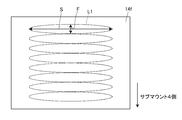
- FIG. 6 is a diagram showing the spread of light incident on the incident surface 14f of the first condenser lens 14 shown in FIG.
- the respective lights L1 emitted from the plurality of laser diodes 11 are arranged so that the fast axes are aligned with each other by the reflection of the plurality of mirrors 13 as described above. For this reason, when entering the incident surface 14f of the 1st condensing lens 14, each light L1 is arranged in the fast-axis F direction mutually.
- the light in the fast axis F direction emitted from the laser diode 11 is easily collimated because it is a single mode, and the light in the slow axis S direction is multimode and is collimated compared to the light in the fast axis F direction. It is hard to be done. For this reason, as shown in FIG. 6, the light L1 incident on the first condenser lens 14 is light having a small spread in the fast axis F direction with respect to the slow axis S direction.
- the light incident on the first condenser lens 14 is condensed in the fast axis direction as described above.
- the light emitted from the first condenser lens 14 enters the second condenser lens 15, and is condensed in the slow axis direction of the light by the second condenser lens 15.
- the light collected by the second condenser lens 15 enters the core of the optical fiber 50 and propagates through the optical fiber 50. Thus, light is emitted from the other end of the optical fiber 50.
- the optical module 1 includes the laser diodes 11 that are a plurality of light emitting elements arranged on the same plane, and the plurality of mirrors 13 provided on the light emission direction side of each of the plurality of laser diodes 11. Prepare. As described above, in the optical module 1, by arranging the laser diodes 11 on the same plane, it becomes easy to align the lengths of the heat radiation paths of the heat emitted from the laser diodes 11. For this reason, the optical module 1 can suppress the occurrence of a difference in the junction temperature of each laser diode 11, and the complexity of the reliability design can be suppressed.
- the plurality of mirrors 13 reflect the respective lights emitted from the respective laser diodes 11 so as to be aligned in the fast axis direction.
- the light emitted from the laser diode 11 is more easily collimated in the fast axis direction than in the slow axis direction.
- the light collimated by being emitted from the plurality of laser diodes 11 is arranged in the fast axis direction, so that the light is easily collected spatially densely.
- the optical module 1 the light emitted from the plurality of laser diodes 11 can be collected spatially densely.
- the optical module 1 can emit light with high output. Therefore, in the optical module 1, multiplexed high-intensity light can propagate through the optical fiber 50.
- the submount 4 on which the plurality of laser diodes 11 are arranged may be planar, and therefore it is easy to form the submount 4 with low cost and high accuracy.
- each mirror 13 In the optical module 1, the light reflected by each mirror 13 is reflected in the direction in which the plurality of mirrors 13 are juxtaposed when viewed from the fast axis direction of the light incident on each mirror 13.
- the optical module 1 it is possible to suppress the light reflected by each mirror 13 from being blocked by the other mirror 13. In this way, the light reflected by the respective mirrors 13 allows the light emitted from the plurality of laser diodes 11 to be used efficiently. For this reason, the light emitted from the plurality of laser diodes 11 can efficiently enter the optical fiber 50.
- a plurality of light refracting members 17 that refract light so that the propagation directions of the respective lights reflected by the plurality of mirrors 13 approach parallel to the optical axis of the first condenser lens 14 are provided. Are provided between the mirror 13 and the first condenser lens 14. By providing such a light refraction member 17, even if the propagation direction of the light reflected by the mirror 13 and the optical axis of the first condenser lens 14 are non-parallel, the first condenser lens It becomes easy for light parallel to the optical axis 14 to enter the first condenser lens 14.
- positioning of the 1st condensing lens 14 for condensing the light reflected by the several mirror 13 can be improved.
- the first condenser lens 14, the second condenser lens 15 and the optical fiber so that the surface on which the plurality of laser diodes 11 are arranged and the optical axis are parallel to each other. Since 50 can be arranged, the optical module 1 can be easily manufactured.
- the mirror 13 has a fixing surface 13f fixed to the submount 4 which is another member, and the fixing surface 13f is parallel to the surface 4f of the submount 4 on which the mirror 13 is fixed.
- the fixing surface 13f of the mirror 13 By forming the fixing surface 13f of the mirror 13 in this way, the adhesive for fixing the fixing surface 13f of the mirror 13 and the submount 4 can be made to have a uniform thickness. For this reason, when the volume of the adhesive changes due to a change in temperature, humidity, or the like, the reflection surface 13r of the mirror 13 can be prevented from being tilted, and the light reflection direction by the mirror 13 can be prevented from changing.
- the plurality of laser diodes 11 are arranged on the same plane, so that the number of the laser diodes 11 arranged is larger than that in the case where the plurality of laser diodes are arranged on the stepped mount.
- the increase in size can be suppressed when there is an increase in.
- the parallel direction of the plurality of laser diodes 11 and the parallel direction of the plurality of mirrors 13 are parallel to each other. For this reason, it can suppress that the area
- FIG. 7 is a view showing the optical module according to the present embodiment from the same viewpoint as FIG.
- the optical module 1a of the present embodiment is different from the first embodiment in that the optical refraction member 17 is not provided. Further, since the optical module 1a does not include the light refraction member 17, the arrangement of the first condenser lens 14, the second condenser lens 15, and the optical fiber 50 is different from that of the first embodiment.
- the optical axes of the first condenser lens 14, the second condenser lens 15, and the optical fiber 50 are inclined with respect to the surface on which the plurality of mirrors 13 are arranged, and the first condenser lens 14. The optical axes of the second condenser lens 15 and the optical fiber 50 overlap in a straight line.
- the incident direction of light at the center of the region where the light reflected by the plurality of mirrors 13 enters and the optical axis of the first condenser lens 14 are parallel. are arranged as follows.
- FIG. 8 is a diagram showing the optical module according to the present embodiment from the same viewpoint as FIG.
- FIG. 9 is an enlarged cross-sectional view of the end of the optical fiber shown in FIG.
- an arrow L2 indicates the light propagation direction.
- the optical module 1b of this embodiment differs from the second embodiment in the arrangement of the optical fiber 50 and the shape of the incident end.
- the optical fiber 50 of the present embodiment is disposed so that the optical axis of the optical fiber 50 is parallel to the surface on which the plurality of laser diodes 11 are disposed.
- the end face 50 f on the light incident side of the optical fiber 50 has an inclined surface that refracts light so that the propagation direction of the light incident on the optical fiber 50 approaches a direction parallel to the optical axis of the optical fiber 50.
- the inclination angle of the end face 50f with respect to the optical axis of the optical fiber 50 is ⁇
- the angle of the propagation direction of light incident on the end face 50f with respect to the optical axis of the optical fiber 50 is ⁇
- the optical fiber 50 When the refractive index of the core of n is n, it is preferable that the following formula (1) is satisfied.
- the propagation direction of the light propagating through the core of the optical fiber 50 can be set to a direction almost parallel to the optical axis of the optical fiber 50. , Light can be prevented from leaking out of the core.
- FIG. 10 is a diagram showing the optical module according to the present embodiment from the same viewpoint as FIG.
- the optical module 1c of the present embodiment is different from the first embodiment in the direction of light reflected by each mirror 13. Further, the arrangement of the light refraction member 17, the first condenser lens 14, the second condenser lens 15, and the optical fiber 50 is different from that of the first embodiment in accordance with the propagation direction of the light reflected by the mirror 13.
- each mirror 13 is arranged so that light reflected by each mirror 13 propagates between the other mirror 13 adjacent to the first condenser lens 14 side and the laser diode 11.
- the light reflected by each mirror 13 propagates in the space opposite to the submount 4 of the other mirror 13 adjacent to the first condenser lens 14 side. And explained. However, as in the fourth embodiment, the light reflected by each mirror 13 propagates through the space on the laser diode 11 side to the other mirror 13 adjacent to the first condenser lens 14 side. A plurality of mirrors 13 may be arranged. The direction in which the light reflected by each mirror 13 propagates is not limited to these embodiments, and the space in any direction may propagate to the adjacent mirror 13 on the first condenser lens 14 side. .
- the submount 4 when the submount 4 is made of a transparent material or part of the mirror 13 on the side of the submount 4 is configured to transmit light, the light reflected by each mirror 13 is first. It may propagate on the submount 4 side of another mirror 13 adjacent to the condenser lens 14 side. However, it is preferable that the light reflected by at least one mirror 13 overlaps at least one other mirror 13 in the fast axis direction. Thus, by propagating the reflected light reflected by the mirror 13 so as to overlap the other mirror 13, the optical module can be miniaturized, for example, by narrowing the distance between the laser diode 11 and the mirror 13.
- the example in which the lights reflected by the plurality of mirrors 13 propagate in directions parallel to each other has been described. Reflecting the light in this way makes it easy to obtain high coupling efficiency when the light is collected by the condenser lens and incident on the optical fiber.
- the plurality of mirrors 13 may reflect the respective lights emitted from the respective laser diodes 11 so as to approach each other in the fast axis direction, and collect these lights at one point by a condenser lens.
- the focal position can be easily brought close to the condenser lens. For this reason, an optical module can be reduced in size.
- the plurality of mirrors 13 may reflect the respective lights emitted from the respective laser diodes 11 so as to be separated from each other in the fast axis direction, and collect these lights at one point by a condenser lens.
- the incident light is incident on the outer peripheral side of the condenser lens, that is, at a position away from the optical axis of the condenser lens.
- the corner can be increased.
- the aberration of the light collected by the condenser lens can be reduced.
- each mirror 13 can be suppressed from being blocked by the other mirror 13.
- the lights emitted from the plurality of laser diodes 11 and reflected by the plurality of mirrors 13 overlap each other when viewed from the fast axis direction.
- the present invention is not limited to such a form.
- the light emitted from each light emitting element may be reflected by a plurality of mirrors so as to overlap at least a part of the light emitted from the other light emitting element when viewed from the fast axis direction.
- an optical module capable of emitting light with high output while suppressing the complexity of reliability design is provided, and used in the field of, for example, a fiber laser device or the like. Can do.
- Optical module 2 Base plate 3 ... Lid 4 ... Submount 4f ... Surface 11 ... Laser diode 12 ... Laser mount 13 ... Mirror 13f ... fixed surface 13r ... reflective surface 14 ... first condenser lens 15 ... second condenser lens 17 ... photorefractive member 50 ... optical fiber 50f ... end face
Abstract
An optical module (1) is provided with: laser diodes (11) that are a plurality of light emitting elements disposed on a same plane; and a plurality of mirrors (13) that reflect beams outputted from respective laser diodes (11). The mirrors (13) reflect the beams in the direction tilted with respect to the plane on which the laser diodes (11) are disposed, said beams having been outputted from respective laser diodes (11), and align the beams with each other in the fast-axis direction.
Description
本発明は、光モジュールに関する。
The present invention relates to an optical module.
光モジュールの一つとして、レーザダイオードから出射する光が光ファイバを介して出射するものが知られている。この光モジュールでは、筐体内から筐体外に光ファイバが導出されており、筐体内には、レーザダイオード、ミラー、レンズ、光ファイバ等の光学部品が配置されている。それぞれのレーザダイオードから出射する光は、集光された後に光ファイバに入射して、筐体外において光ファイバから出射する。
As one of optical modules, one in which light emitted from a laser diode is emitted through an optical fiber is known. In this optical module, an optical fiber is led out from the inside of the casing, and optical components such as a laser diode, a mirror, a lens, and an optical fiber are arranged in the casing. The light emitted from each laser diode is collected and then incident on the optical fiber, and is emitted from the optical fiber outside the housing.
例えば下記特許文献1には、階段状に形成されたマウント上に配置される複数のレーザダイオードと、それぞれのレーザダイオードに対応して設けられるミラーと、それぞれのミラーで反射された光を集光して光ファイバに入射させる集光レンズと、を備える光モジュールが開示されている。
For example, in the following Patent Document 1, a plurality of laser diodes arranged on a step-shaped mount, mirrors provided corresponding to the respective laser diodes, and light reflected by the respective mirrors are collected. An optical module including a condensing lens that is incident on an optical fiber is disclosed.
また、下記特許文献2には、同一平面上に配置される複数のレーザダイオードと、それぞれのレーザダイオードから出射される光をコリメートするコリメート装置と、コリメートされた光の方向を変える回折格子と、それぞれの回折格子で向きを変えられた光を集光して光ファイバに入射させる集光レンズと、を備える光モジュールが開示されている。このような光モジュールに備えられるレーザダイオードは、当該レーザダイオードが配置される面に対して垂直方向に半導体層が積層されてなる。よって、このレーザダイオードから出射される光は、複数のレーザダイオードが配置される面に平行な方向がスロー軸方向とされる。また、下記特許文献2に記載の光モジュールでは、複数のレーザダイオードが配置される面に平行な面内において、それぞれのレーザダイオードから集光レンズまで光が伝搬する。よって、この光モジュールでは、複数のレーザダイオードから出射される光がスロー軸方向に並んで集光レンズに入射する。
Further, in Patent Document 2 below, a plurality of laser diodes arranged on the same plane, a collimator device that collimates light emitted from each laser diode, a diffraction grating that changes the direction of the collimated light, An optical module is disclosed that includes a condensing lens that condenses the light whose direction is changed by each diffraction grating and makes the light incident on an optical fiber. The laser diode provided in such an optical module is formed by stacking semiconductor layers in a direction perpendicular to the surface on which the laser diode is arranged. Therefore, the light emitted from this laser diode is set to the slow axis direction in the direction parallel to the surface on which the plurality of laser diodes are arranged. In the optical module described in Patent Document 2 below, light propagates from each laser diode to the condenser lens in a plane parallel to the plane on which the plurality of laser diodes are arranged. Therefore, in this optical module, the light emitted from the plurality of laser diodes enters the condenser lens side by side in the slow axis direction.
上記のような光モジュールでは、レーザダイオードが発する熱はマウントを介してヒートシンクへと伝えられる。ここで、上記特許文献1に記載の光モジュールのように階段状に形成されたマウント上に複数のレーザダイオードが配置される場合、各レーザダイオードで放熱経路の長さに差が生じる。このため、各レーザダイオードのジャンクション温度に差が生じやすくなる。各レーザダイオードのジャンクション温度に差が生じる場合、各レーザダイオードの寿命に差が生じ、光モジュールの信頼性設計が複雑になるという懸念がある。
In the optical module as described above, the heat generated by the laser diode is transmitted to the heat sink via the mount. Here, when a plurality of laser diodes are arranged on a step-like mount as in the optical module described in Patent Document 1, a difference occurs in the length of the heat dissipation path between the laser diodes. For this reason, it becomes easy to produce the difference in the junction temperature of each laser diode. When a difference occurs in the junction temperature of each laser diode, there is a concern that a difference occurs in the lifetime of each laser diode, and the reliability design of the optical module becomes complicated.
また、上記特許文献2に記載の光モジュールでは、上記のように複数のレーザダイオードから出射される光がスロー軸方向に並べられる。しかし、レーザダイオードから出射される光はファスト軸に比べてスロー軸方向にコリメートされ難い。このため、上記特許文献2に記載された光モジュールでは、複数のレーザダイオードから出射される光を狭い領域に集光させ難く、高出力化が難しいという懸念がある。
In the optical module described in Patent Document 2, the light emitted from the plurality of laser diodes is arranged in the slow axis direction as described above. However, the light emitted from the laser diode is less likely to be collimated in the slow axis direction than the fast axis. For this reason, in the optical module described in Patent Document 2, there is a concern that it is difficult to condense light emitted from a plurality of laser diodes in a narrow region and it is difficult to increase output.
そこで、本発明は、信頼性設計の複雑化が抑制され、高出力化された光を出射し得る光モジュールを提供することを目的とする。
Therefore, an object of the present invention is to provide an optical module capable of emitting light with high output while suppressing the complexity of reliability design.
本発明の光モジュールは、同一平面上に配置される複数の発光素子と、それぞれの前記発光素子から出射されるそれぞれの光を反射する複数のミラーと、を備え、前記複数のミラーは、それぞれの前記発光素子から出射するそれぞれの光を前記平面に対して傾斜した方向に反射して互いにファスト軸方向に並べることを特徴とする。
The optical module of the present invention includes a plurality of light emitting elements arranged on the same plane, and a plurality of mirrors that reflect the respective lights emitted from the respective light emitting elements, and the plurality of mirrors are respectively The light emitted from the light emitting element is reflected in a direction inclined with respect to the plane and aligned in the fast axis direction.
上記光モジュールでは、それぞれの発光素子が同一平面上に配置されることによって、それぞれの発光素子から放出される熱の放熱経路の長さを揃え易くなる。このため、上記光モジュールは、それぞれの発光素子のジャンクション温度に差が生じることを抑制し、信頼性設計の複雑化が抑制され得る。また、上記光モジュールでは、複数の発光素子から出射される光が反射によりファスト軸方向に並べられることによって、複数の発光素子から出射される光が空間的に密に集められ得る。このため、上記光モジュールは、高出力化された光を出射し得る。
In the above optical module, by arranging the respective light emitting elements on the same plane, it becomes easy to align the lengths of the heat radiation paths of the heat emitted from the respective light emitting elements. For this reason, the said optical module suppresses that a difference arises in the junction temperature of each light emitting element, and the complexity of reliability design can be suppressed. In the optical module, the light emitted from the plurality of light emitting elements is arranged in the fast axis direction by reflection, so that the light emitted from the plurality of light emitting elements can be collected spatially densely. For this reason, the optical module can emit light with high output.
また、それぞれの前記発光素子から出射するそれぞれの光がそれぞれの前記ミラーに入射する方向とそれぞれの前記ミラーで反射されて出射する方向との成す角θが、0°より大きく90°より小さいことが好ましい。
In addition, an angle θ between the direction in which each light emitted from each light emitting element is incident on each mirror and the direction in which each light is reflected and emitted from each mirror is greater than 0 ° and smaller than 90 °. Is preferred.
このようにそれぞれの発光素子から出射するそれぞれの光が所定の角度で反射されることによって、複数の発光素子から出射される光を反射によりファスト軸方向に並べ易くなる。
As described above, each light emitted from each light emitting element is reflected at a predetermined angle, so that the light emitted from the plurality of light emitting elements can be easily arranged in the fast axis direction by reflection.
また、少なくとも一つの前記ミラーで反射された光は、ファスト軸方向において少なくとも一つの他の前記ミラーと重なることが好ましい。
Further, it is preferable that the light reflected by at least one of the mirrors overlaps with at least one other mirror in the fast axis direction.
このようにミラーで反射された反射光を他のミラーと重なるようにして伝搬させることにより、発光素子とミラーとの間隔を狭める等して光モジュールを小型化し得る。
In this way, the reflected light reflected by the mirror is propagated so as to overlap with other mirrors, so that the optical module can be miniaturized by narrowing the distance between the light emitting element and the mirror.
また、それぞれの前記ミラーで反射される光は、それぞれの前記ミラーに入射する光のファスト軸方向から見て前記複数のミラーが並列される方向に反射されることが好ましい。
Further, it is preferable that the light reflected by each of the mirrors is reflected in a direction in which the plurality of mirrors are juxtaposed when viewed from the fast axis direction of the light incident on each of the mirrors.
このようにしてそれぞれのミラーで光が反射されることによって、それぞれのミラーで反射されるそれぞれの光がスロー軸方向に互いにずれることが抑制され得る。このため、それぞれのミラーで反射されるそれぞれの光が狭い領域に集光され得る。
In this way, the light reflected by the respective mirrors can suppress the deviation of the respective lights reflected by the respective mirrors in the slow axis direction. For this reason, each light reflected by each mirror can be condensed in a narrow region.
また、前記複数のミラーは、それぞれの前記発光素子から出射するそれぞれの光を伝搬方向が互いに平行となるように反射することが好ましい。
Further, it is preferable that the plurality of mirrors reflect the respective light emitted from the respective light emitting elements so that the propagation directions thereof are parallel to each other.
このように光が反射されることによって、これらの光を集光レンズで集光して光ファイバに入射させる際に、高い結合効率を得やすくなる。
Such reflection of light makes it easy to obtain high coupling efficiency when the light is collected by the condenser lens and incident on the optical fiber.
あるいは、前記複数のミラーで反射された光が入射する集光レンズを更に備え、それぞれの前記発光素子から出射するそれぞれの光は、前記複数のミラーによってファスト軸方向において互いに近づくように反射され、前記集光レンズによって一点に集光されることも好ましい。
Or, further comprising a condenser lens on which the light reflected by the plurality of mirrors is incident, each light emitted from each light emitting element is reflected by the plurality of mirrors so as to approach each other in the fast axis direction, It is also preferable that the light is condensed at one point by the condensing lens.
このようにして互いに近づくように反射された光を集光レンズで集光することによって、焦点位置を集光レンズに近付け易くなる。このため、光モジュールを小型化し得る。
In this way, by condensing the light reflected so as to approach each other with the condenser lens, the focal position can be easily brought close to the condenser lens. For this reason, an optical module can be reduced in size.
あるいはまた、前記複数のミラーで反射された光が入射する集光レンズを更に備え、それぞれの前記発光素子から出射するそれぞれの光は、前記複数のミラーによってファスト軸方向において互いに離れるように反射され、前記集光レンズによって一点に集光されることも好ましい。
Alternatively, it further includes a condensing lens on which the light reflected by the plurality of mirrors is incident, and each light emitted from each of the light emitting elements is reflected away from each other in the fast axis direction by the plurality of mirrors. It is also preferable that the light is condensed at one point by the condenser lens.
このように互いに離れるように複数のミラーで反射された光が集光レンズに入射するとき、集光レンズの外周側すなわち集光レンズの光軸から離れた位置に入射する光の入射角を大きくすることができる。このように集光レンズに光が入射することによって、集光レンズで集光される光の収差が小さくされ得る。
When the light reflected by the plurality of mirrors enters the condenser lens so as to be separated from each other in this way, the incident angle of the light incident on the outer peripheral side of the condenser lens, that is, the position away from the optical axis of the condenser lens is increased. can do. Thus, when light enters the condenser lens, the aberration of the light collected by the condenser lens can be reduced.
また、前記複数のミラーで反射された光が入射する集光レンズと、前記複数のミラーと前記集光レンズとの間に配置される光屈折部材と、を更に備え、前記光屈折部材は、前記複数のミラーによって反射されたそれぞれの光の伝搬方向が前記集光レンズの光軸に対して平行に近づくように光を屈折させることが好ましい。
The light refracting member may further include a condenser lens on which light reflected by the plurality of mirrors is incident, and a light refracting member disposed between the plurality of mirrors and the condenser lens. It is preferable that light is refracted so that the propagation direction of each light reflected by the plurality of mirrors approaches parallel to the optical axis of the condenser lens.
このような光屈折部材が備えられることによって、ミラーで反射された光の伝搬方向と集光レンズの光軸とが非平行である場合であっても、集光レンズの光軸に平行な光を集光レンズに入射させ易くなる。このため、複数のミラーで反射された光を集光するための集光レンズの設計及び配置の自由度が向上され得る。
By providing such a light refraction member, even if the propagation direction of the light reflected by the mirror and the optical axis of the condensing lens are non-parallel, the light parallel to the optical axis of the condensing lens Is easily incident on the condenser lens. For this reason, the freedom degree of design and arrangement | positioning of the condensing lens for condensing the light reflected by the some mirror can be improved.
あるいは、前記複数のミラーで反射された光が入射する集光レンズを更に備え、前記集光レンズは、前記複数のミラーによって反射された光が入射する領域の中心における光の入射方向と前記集光レンズの光軸とが互いに平行となるように配置されることも好ましい。
Alternatively, the optical system further includes a condensing lens on which the light reflected by the plurality of mirrors is incident, and the condensing lens includes the incident direction of the light at the center of the region where the light reflected by the plurality of mirrors is incident and the collection It is also preferable that the optical axes of the optical lenses are arranged so as to be parallel to each other.
このように集光レンズが配置されることによって、上記のような光屈折部材を用いずに、光軸に平行な光を集光レンズに入射させ易くなる。
By arranging the condensing lens in this way, it becomes easy to make light parallel to the optical axis incident on the condensing lens without using the light refraction member as described above.
また、前記複数のミラーで反射された光が入射する光ファイバを更に備え、前記光ファイバのうち光が入射する側の端面は、前記光ファイバに入射する光の伝搬方向が前記光ファイバの光軸と平行な方向に近づくように光を屈折させる傾斜面を有することが好ましい。
The optical fiber further includes an optical fiber on which light reflected by the plurality of mirrors is incident, and the end surface on the light incident side of the optical fiber has a propagation direction of the light incident on the optical fiber. It is preferable to have an inclined surface that refracts light so as to approach a direction parallel to the axis.
光ファイバの端面にこのような傾斜面が形成されることによって、光ファイバのコアを伝搬する光の伝搬方向を光ファイバの光軸に対して平行に近い方向とすることができるので、光がコアから漏れ出ることが抑制され得る。
By forming such an inclined surface on the end face of the optical fiber, the propagation direction of the light propagating through the core of the optical fiber can be made to be a direction nearly parallel to the optical axis of the optical fiber. Leakage from the core can be suppressed.
また、前記ミラーは他の部材に固定される固定面を有し、前記固定面は前記他の部材のうち前記ミラーが固定される面に対して平行とされることが好ましい。
Further, it is preferable that the mirror has a fixed surface fixed to another member, and the fixed surface is parallel to a surface of the other member to which the mirror is fixed.
このようにミラーの固定面が形成されることによって、ミラーの固定面と他の部材とを固定する接着剤を均一な厚さとし得る。このため、温度や湿度の変化等によって接着剤の体積が変化する場合にミラーの反射面が傾くことが抑制され、ミラーによる光の反射方向が変化することが抑制され得る。
By forming the fixed surface of the mirror in this way, the adhesive for fixing the fixed surface of the mirror and other members can be made to have a uniform thickness. For this reason, when the volume of the adhesive changes due to a change in temperature, humidity, or the like, it is possible to suppress the reflection surface of the mirror from being inclined, and it is possible to suppress a change in the direction of light reflection by the mirror.
以上のように、本発明によれば、信頼性設計の複雑化が抑制され、高出力化された光を出射し得る光モジュールが提供される。
As described above, according to the present invention, it is possible to provide an optical module capable of emitting light with high output while suppressing the complexity of reliability design.
以下、本発明に係る光モジュールの好適な実施形態について図面を参照しながら詳細に説明する。
Hereinafter, preferred embodiments of an optical module according to the present invention will be described in detail with reference to the drawings.
(第1実施形態)
図1は、本実施形態に係る光モジュールを示す斜視図である。図1に示すように、本実施形態の光モジュール1は、ベースプレート2及び蓋体3から成る筐体と、筐体内に固定される後述の光学部品と、一部の光学部品に電力を供給するコネクタ41とを備えている。 (First embodiment)
FIG. 1 is a perspective view showing an optical module according to this embodiment. As shown in FIG. 1, theoptical module 1 according to the present embodiment supplies power to a housing composed of a base plate 2 and a lid 3, optical components to be described later fixed in the housing, and some optical components. And a connector 41.
図1は、本実施形態に係る光モジュールを示す斜視図である。図1に示すように、本実施形態の光モジュール1は、ベースプレート2及び蓋体3から成る筐体と、筐体内に固定される後述の光学部品と、一部の光学部品に電力を供給するコネクタ41とを備えている。 (First embodiment)
FIG. 1 is a perspective view showing an optical module according to this embodiment. As shown in FIG. 1, the
図2は、図1に示す光モジュール1の蓋体3を外した図である。図2では、レーザダイオード11から出射する光の光路が破線で示されている。また、図3は、図2に示すIII-III線に沿った光モジュール1の断面図である。
FIG. 2 is a view in which the lid 3 of the optical module 1 shown in FIG. 1 is removed. In FIG. 2, the optical path of the light emitted from the laser diode 11 is indicated by a broken line. FIG. 3 is a cross-sectional view of the optical module 1 taken along line III-III shown in FIG.
ベースプレート2は、筐体の底板となる底面が平面状のプレートであり、本実施形態では図2及び図3に示すように平板状の部材である。ベースプレート2は金属から成り、ベースプレート2を構成する金属としては銅やステンレススチール等を挙げることができる。ベースプレート2には外周部に複数のねじ孔27が形成されている。
The base plate 2 is a plate having a flat bottom surface serving as a bottom plate of the housing. In the present embodiment, the base plate 2 is a flat plate member as shown in FIGS. The base plate 2 is made of metal, and examples of the metal constituting the base plate 2 include copper and stainless steel. A plurality of screw holes 27 are formed in the outer peripheral portion of the base plate 2.
ベースプレート2上には、はんだ7によってサブマウント4が固定されている。サブマウント4は、平板状の基板であり、ベースプレート2よりも線膨脹係数が小さな材料から成る。例えば、ベースプレート2が銅から成る場合、サブマウント4は窒化アルミからなる。このようにサブマウント4が小さい線膨脹係数の材料から成ることによって、サブマウント4上に配置される光学部品が発する熱によるサブマウント4の膨張によって光モジュール1の光学的特性が変化することが抑制され得る。
The submount 4 is fixed on the base plate 2 by solder 7. The submount 4 is a flat substrate and is made of a material having a smaller linear expansion coefficient than that of the base plate 2. For example, when the base plate 2 is made of copper, the submount 4 is made of aluminum nitride. As the submount 4 is made of a material having a small linear expansion coefficient, the optical characteristics of the optical module 1 may change due to the expansion of the submount 4 due to the heat generated by the optical components arranged on the submount 4. Can be suppressed.
サブマウント4上には、光ファイバ50を含む光学部品が固定されている。本実施形態の光学部品は、発光素子であるレーザダイオード11、コリメートレンズ16、ミラー13、光屈折部材17、集光レンズである第1集光レンズ14及び第2集光レンズ15、光ファイバ50を含んで構成される。
On the submount 4, optical components including the optical fiber 50 are fixed. The optical components of the present embodiment include a laser diode 11 that is a light emitting element, a collimating lens 16, a mirror 13, a light refraction member 17, a first condensing lens 14 and a second condensing lens 15 that are condensing lenses, and an optical fiber 50. It is comprised including.
それぞれのレーザダイオード11は、活性層を含む複数の半導体層が積層されて成るファブリペロー構造を有する素子であり、例えば波長が900nm帯のレーザ光を出射する。また、それぞれのレーザダイオード11は、同一平面上に配置される。本実施形態では、それぞれのレーザダイオード11の活性層が一つの仮想の平面と重なるように、複数のレーザダイオード11が配置される。また、本実施形態では、それぞれのレーザダイオード11は、レーザマウント12上にはんだ等により固定されており、レーザマウント12を介してサブマウント4上に固定されている。レーザマウント12は、レーザダイオード11の高さを調整するための台であり、それぞれのレーザマウント12は、サブマウント4における外周側の位置に例えばはんだ付け等により固定されている。なお、このようにレーザマウント12がサブマウント4と別体とされて、レーザマウント12がサブマウント4上に固定されても良いが、レーザマウント12がサブマウント4と一体に成型されても良い。或いは、レーザダイオード11の高さ調整が不要の場合、このレーザマウント12は省略されても良い。
Each laser diode 11 is an element having a Fabry-Perot structure formed by laminating a plurality of semiconductor layers including an active layer, and emits a laser beam having a wavelength of, for example, 900 nm. Each laser diode 11 is arranged on the same plane. In the present embodiment, the plurality of laser diodes 11 are arranged so that the active layers of the respective laser diodes 11 overlap one virtual plane. In the present embodiment, each laser diode 11 is fixed on the laser mount 12 with solder or the like, and is fixed on the submount 4 via the laser mount 12. The laser mount 12 is a table for adjusting the height of the laser diode 11, and each laser mount 12 is fixed to a position on the outer peripheral side of the submount 4 by, for example, soldering. In this way, the laser mount 12 may be separated from the submount 4 and the laser mount 12 may be fixed on the submount 4. Alternatively, the laser mount 12 may be molded integrally with the submount 4. . Alternatively, the laser mount 12 may be omitted when the height adjustment of the laser diode 11 is unnecessary.
コリメートレンズ16は、それぞれのレーザダイオード11に対応してレーザマウント12上に配置されている。コリメートレンズ16は、レーザダイオード11から出射する光のファスト軸方向の光、スロー軸方向の光をコリメートするレンズであり、一般的にファスト軸方向の光をコリメートするレンズとスロー軸方向の光のコリメートするレンズとの組み合わせからなる。またコリメートレンズ16は、レーザダイオード11と共にレーザマウント12上に接着等により固定されている。なお、上記のようにレーザマウント12が省略される場合、コリメートレンズ16は、レーザダイオード11と共にサブマウント4上に固定される。
The collimating lens 16 is disposed on the laser mount 12 corresponding to each laser diode 11. The collimating lens 16 is a lens that collimates the light in the fast axis direction and the light in the slow axis direction of the light emitted from the laser diode 11, and generally collimates the light in the fast axis direction and the light in the slow axis direction. It consists of a combination with a collimating lens. The collimating lens 16 is fixed on the laser mount 12 together with the laser diode 11 by adhesion or the like. When the laser mount 12 is omitted as described above, the collimating lens 16 is fixed on the submount 4 together with the laser diode 11.
それぞれのミラー13はそれぞれのレーザダイオード11における光の出射方向側に設けられ、一つレーザダイオード11に対して一つのミラー13が設けられる。よって、ミラー13は、レーザダイオード11から出射してコリメートされた光を直接反射することができる。また、本実施形態では、複数のミラー13は、複数のレーザダイオード11の並列方向と平行に並列される。
Each mirror 13 is provided on the light emitting direction side of each laser diode 11, and one mirror 13 is provided for each laser diode 11. Therefore, the mirror 13 can directly reflect the light emitted from the laser diode 11 and collimated. In the present embodiment, the plurality of mirrors 13 are arranged in parallel with the parallel direction of the plurality of laser diodes 11.
図3に示すように、それぞれのミラー13は、レーザダイオード11からの光を反射する反射面13rとサブマウント4に固定される固定面13fとを有する。また、それぞれのミラー13において、反射面13rと固定面13fとの成す角は鋭角とされる。このため、固定面13fがサブマウント4の表面4fに対して平行となるようにミラー13が配置されることによって、反射面13rはサブマウント4の表面4fの法線に対して傾斜した傾斜面とされる。それぞれのミラー13が上記のように傾斜した反射面13rを有しており、後に詳述するように、複数のミラー13は、それぞれのレーザダイオード11から出射するそれぞれの光を互いにファスト軸方向に並ぶように反射することができる。また、本実施形態では、それぞれのミラー13で反射される光が他のミラー13に遮られることが抑制され得るように複数のミラー13が配置されている。例えば、それぞれのミラー13で反射される光の95%以上が他のミラー13で遮られないことが好ましい。
As shown in FIG. 3, each mirror 13 has a reflection surface 13 r that reflects light from the laser diode 11 and a fixed surface 13 f that is fixed to the submount 4. In each mirror 13, the angle formed by the reflecting surface 13r and the fixed surface 13f is an acute angle. For this reason, the reflecting surface 13r is inclined with respect to the normal of the surface 4f of the submount 4 by arranging the mirror 13 so that the fixed surface 13f is parallel to the surface 4f of the submount 4. It is said. Each mirror 13 has the reflecting surface 13r inclined as described above, and as will be described in detail later, the plurality of mirrors 13 emit light from each laser diode 11 in the fast axis direction. It can be reflected in a line. In this embodiment, a plurality of mirrors 13 are arranged so that light reflected by each mirror 13 can be suppressed from being blocked by other mirrors 13. For example, it is preferable that 95% or more of the light reflected by each mirror 13 is not blocked by the other mirror 13.
本実施形態のミラー13は、例えば誘電体多層膜からなる反射膜によって反射面13rが表面に形成されたガラス体であり、固定面13fがサブマウント4の表面4fに接着剤により固定されている。このようなミラー13は、例えば直方体状のガラス体のうち固定面13fが形成される側の面を斜めに削った後に反射膜を形成することによって得られる。なお、反射面13rは金属膜によって形成されても良く、ミラー13はプリズムから構成されても良い。
The mirror 13 of the present embodiment is a glass body having a reflective surface 13r formed on the surface by a reflective film made of a dielectric multilayer film, for example, and the fixed surface 13f is fixed to the surface 4f of the submount 4 with an adhesive. . Such a mirror 13 can be obtained, for example, by forming a reflective film after obliquely shaving the surface of the rectangular parallelepiped glass body on which the fixed surface 13f is formed. The reflecting surface 13r may be formed of a metal film, and the mirror 13 may be formed of a prism.
光屈折部材17は、複数のミラー13と第1集光レンズ14との間に備えられ、サブマウント4に接着により固定されている。光屈折部材17は、複数のミラー13によって反射されたそれぞれの光の伝搬方向が第1集光レンズ14の光軸に対して平行に近づくように光を屈折させる。本実施形態の光屈折部材17は、ミラー13側の面と第1集光レンズ14側の面とが非平行に形成されている。光屈折部材17はサブマウント4に固定される底面を有し、光屈折部材17のうち第1集光レンズ14側となる面は底面に対して垂直に形成され、ミラー13側となる面は底面との成す角が鋭角となるように形成されている。このため、光屈折部材17の底面がサブマウント4の表面4fと平行に固定された状態において、複数のミラー13で反射された光が光屈折部材17に入射してから透過するまでの距離は、サブマウント4から離れるに従って小さくなる。このような光屈折部材17は、ウェッジ基板であり、例えばガラスから成る。
The photorefractive member 17 is provided between the plurality of mirrors 13 and the first condenser lens 14 and is fixed to the submount 4 by adhesion. The light refracting member 17 refracts the light so that the propagation direction of each light reflected by the plurality of mirrors 13 approaches parallel to the optical axis of the first condenser lens 14. In the photorefractive member 17 of this embodiment, the surface on the mirror 13 side and the surface on the first condenser lens 14 side are formed non-parallel. The light refracting member 17 has a bottom surface fixed to the submount 4. The surface of the light refracting member 17 on the first condenser lens 14 side is formed perpendicular to the bottom surface, and the surface on the mirror 13 side is The angle formed with the bottom surface is formed to be an acute angle. For this reason, in a state where the bottom surface of the light refracting member 17 is fixed in parallel with the surface 4f of the submount 4, the distance from when the light reflected by the plurality of mirrors 13 enters the light refracting member 17 until it is transmitted is As the distance from the submount 4 increases, the distance decreases. Such a light refraction member 17 is a wedge substrate and is made of, for example, glass.
第1集光レンズ14及び第2集光レンズ15は、それぞれシリンドリカルレンズから成り、サブマウント4に接着により固定されている。第1集光レンズ14は、それぞれのミラー13で反射される光をファスト軸方向に集光し、第2集光レンズ15は、第1集光レンズ14から出射する光をスロー軸方向に集光する。本実施形態では、第1集光レンズ14及び第2集光レンズ15は、第1集光レンズ14の光軸及び第2集光レンズ15の光軸が複数のレーザダイオード11が配置される面と平行となるように配置される。また、本実施形態では、第1集光レンズ14の光軸と第2集光レンズ15の光軸とが一直線上となるように第1集光レンズ14及び第2集光レンズ15が配置される。さらに、第1集光レンズ14は、複数のミラー13によって反射された光が光屈折部材17を介して入射する領域の中心における光の入射方向と第1集光レンズ14の光軸とが平行となるように配置される。なお、これらの集光レンズから出射する光が所望の位置で集光しない場合には、他の集光レンズが更にサブマウント4上に配置されても良い。
The first condenser lens 14 and the second condenser lens 15 are each composed of a cylindrical lens, and are fixed to the submount 4 by adhesion. The first condenser lens 14 condenses the light reflected by the respective mirrors 13 in the fast axis direction, and the second condenser lens 15 collects the light emitted from the first condenser lens 14 in the slow axis direction. Shine. In the present embodiment, the first condenser lens 14 and the second condenser lens 15 are surfaces on which the plurality of laser diodes 11 are arranged on the optical axis of the first condenser lens 14 and the optical axis of the second condenser lens 15. Are arranged in parallel with each other. In the present embodiment, the first condenser lens 14 and the second condenser lens 15 are arranged so that the optical axis of the first condenser lens 14 and the optical axis of the second condenser lens 15 are aligned. The Further, in the first condenser lens 14, the incident direction of light at the center of the region where the light reflected by the plurality of mirrors 13 enters through the photorefractive member 17 is parallel to the optical axis of the first condenser lens 14. It arrange | positions so that it may become. In addition, when the light emitted from these condenser lenses is not condensed at a desired position, another condenser lens may be further disposed on the submount 4.
光ファイバ50は、パイプ状のホルダ51に挿通されて、ホルダ51に固定されている。本実施形態では、光ファイバ50の光の入射端となる一端がホルダ51から僅かに導出されている。ホルダ51はファイバマウント52に固定され、ファイバマウント52はサブマウント4に固定されている。光ファイバ50の一端は、第2集光レンズ15から出射する光が、コアに入射可能な位置とされる。本実施形態では、光ファイバ50は、光ファイバ50の光軸が複数のレーザダイオード11が配置される面と平行となるように配置される。なお、本実施形態では、光ファイバ50はホルダ51に接着剤やはんだ付けにより固定されており、ホルダ51はファイバマウント52に接着されることで固定され、ファイバマウント52はサブマウント4に接着により固定されている。
The optical fiber 50 is inserted into a pipe-shaped holder 51 and fixed to the holder 51. In the present embodiment, one end serving as the light incident end of the optical fiber 50 is slightly led out from the holder 51. The holder 51 is fixed to the fiber mount 52, and the fiber mount 52 is fixed to the submount 4. One end of the optical fiber 50 is at a position where light emitted from the second condenser lens 15 can enter the core. In the present embodiment, the optical fiber 50 is disposed so that the optical axis of the optical fiber 50 is parallel to the surface on which the plurality of laser diodes 11 are disposed. In this embodiment, the optical fiber 50 is fixed to the holder 51 by an adhesive or soldering, the holder 51 is fixed by being bonded to the fiber mount 52, and the fiber mount 52 is bonded to the submount 4 by bonding. It is fixed.
コネクタ41は、一対の棒状の導体から形成されており、それぞれの導体は一対のコネクタホルダ42に固定されている。それぞれのコネクタホルダ42は、サブマウント4に接着されて固定されている。コネクタ41の一方の導体は、コネクタ41に最も近いレーザダイオード11と図示しない金線により接続されており、それぞれのレーザダイオード11は図示しない金線によりデイジーチェーン接続されている。また、コネクタ41から最も離れたレーザダイオード11は、コネクタ41の他方の導体に図示しない金線により接続されている。
The connector 41 is formed of a pair of rod-shaped conductors, and each conductor is fixed to a pair of connector holders 42. Each connector holder 42 is bonded and fixed to the submount 4. One conductor of the connector 41 is connected to the laser diode 11 closest to the connector 41 by a gold wire (not shown), and each laser diode 11 is daisy chain connected by a gold wire (not shown). The laser diode 11 farthest from the connector 41 is connected to the other conductor of the connector 41 by a gold wire (not shown).
蓋体3は、金属板がプレス加工されて成り、図1に示すように、トッププレート31と、枠体32と、鍔部33とから成る。トッププレート31は、筐体の天板となる部位であり、平板状の部材からなる。枠体32は、トッププレート31の周縁においてトッププレート31に垂直に連結される部位である。また、枠体32は、蓋体3がベースプレート2上に配置された状態で、サブマウント4及びサブマウント4上の光学部品等を囲む大きさとされる。また、枠体32及び鍔部33には、光ファイバ50を筐体内から筐体外に導出するための切り欠き、および、コネクタ41を筐体内から筐体外に導出するための切り欠きが形成されている。また、鍔部33には複数のねじ孔が形成されており、これらのねじ孔とベースプレート2のそれぞれのねじ孔27とにねじ25が螺入されることにより、ベースプレート2と蓋体3とが固定される。
The lid 3 is formed by pressing a metal plate, and includes a top plate 31, a frame 32, and a flange 33 as shown in FIG. The top plate 31 is a portion that becomes a top plate of the housing, and is made of a flat member. The frame body 32 is a part that is vertically connected to the top plate 31 at the periphery of the top plate 31. Further, the frame body 32 has a size that surrounds the submount 4 and the optical components on the submount 4 in a state where the lid 3 is disposed on the base plate 2. The frame 32 and the flange 33 are formed with a notch for leading the optical fiber 50 from the inside of the housing to the outside of the housing and a notch for leading the connector 41 from the inside of the housing to the outside of the housing. Yes. In addition, a plurality of screw holes are formed in the flange portion 33, and the base plate 2 and the lid 3 are connected to each other by screwing the screws 25 into these screw holes and the respective screw holes 27 of the base plate 2. Fixed.
次に、光モジュール1の光学的な動作について説明する。
Next, the optical operation of the optical module 1 will be described.
コネクタ41からそれぞれのレーザダイオード11に所望の電力が供給されると、図2に示すように、それぞれのレーザダイオード11は、それぞれのレーザダイオード11に対応するそれぞれのコリメートレンズ16に向かって光を出射する。この光は、上記のように例えば波長が900nm帯のレーザ光とされる。また、それぞれのレーザダイオード11から出射される光は、ファスト軸方向が複数のレーザダイオード11が配置される平面に対して直交する方向とされ、スロー軸方向が複数のレーザダイオード11が並列される方向と平行な方向とされる。
When desired power is supplied from the connector 41 to each laser diode 11, each laser diode 11 emits light toward each collimating lens 16 corresponding to each laser diode 11 as shown in FIG. 2. Exit. This light is, for example, laser light having a wavelength of 900 nm as described above. The light emitted from each laser diode 11 has a fast axis direction orthogonal to a plane on which the plurality of laser diodes 11 are arranged, and a slow axis direction in which the plurality of laser diodes 11 are arranged in parallel. The direction is parallel to the direction.
それぞれのコリメートレンズ16では、レーザダイオード11から出射する光をコリメートして出射する。それぞれのコリメートレンズ16から出射した光は、対応するそれぞれのミラー13に入射する。それぞれのミラー13は、入射する光を次に説明するように反射する。
Each collimating lens 16 collimates and emits the light emitted from the laser diode 11. The light emitted from each collimator lens 16 enters the corresponding mirror 13. Each mirror 13 reflects incident light as described below.
図4は、図2に示すミラー13によって反射される光の光路を示す平面図である。図5は、図2に示すミラー13によって反射される光の光路を示す側面図である。図4及び図5では、光モジュール1に備えられる一部の部材のみが概略的に示されており、それぞれのレーザダイオード11から出射する光の光路が破線で示されている。なお、第1集光レンズ14及び第2集光レンズ15は、図示しない台座を介してサブマウント4に固定されている。
FIG. 4 is a plan view showing an optical path of light reflected by the mirror 13 shown in FIG. FIG. 5 is a side view showing an optical path of light reflected by the mirror 13 shown in FIG. 4 and 5, only some members provided in the optical module 1 are schematically shown, and the optical paths of the light emitted from the respective laser diodes 11 are indicated by broken lines. The first condenser lens 14 and the second condenser lens 15 are fixed to the submount 4 via a pedestal (not shown).
本実施形態では、それぞれのミラー13で反射される光は、それぞれのミラー13に入射する光のファスト軸方向から見て複数のミラー13が並列される方向に反射される。また、本実施形態のミラー13の反射面13rは上記のように傾斜しており、複数のミラー13は、それぞれのレーザダイオード11から出射するそれぞれの光をレーザダイオード11が配置される平面、すなわちサブマウント4の表面4fに対して傾斜した方向に反射させることができる。それぞれのレーザダイオード11から出射するそれぞれの光がそれぞれのミラー13に入射する方向とそれぞれのミラー13で反射されて出射する方向との成す角θは、0°より大きく90°より小さくされる。このため、それぞれのミラー13で反射される光は、図4及び図5に示すように、第1集光レンズ14側の隣に配置される他のミラー13のサブマウント4とは反対側の空間を伝搬する。このようにして、複数のミラー13は、それぞれのレーザダイオード11から出射するそれぞれの光を互いにファスト軸方向に並ぶように反射することができる。さらに、本実施形態では、複数のミラー13は、それぞれのレーザダイオード11から出射するそれぞれの光を伝搬方向が互いに平行となるように反射する。すなわち、それぞれのレーザダイオード11から出射される光が互いに平行である場合、それぞれのミラー13の反射面13rはサブマウント4の表面4fに対して概ね同じ角度とされる。
In this embodiment, the light reflected by each mirror 13 is reflected in a direction in which a plurality of mirrors 13 are arranged in parallel when viewed from the fast axis direction of the light incident on each mirror 13. Further, the reflecting surface 13r of the mirror 13 of the present embodiment is inclined as described above, and the plurality of mirrors 13 are planes on which the laser diodes 11 are arranged, that is, the light beams emitted from the respective laser diodes 11, respectively. The light can be reflected in a direction inclined with respect to the surface 4 f of the submount 4. An angle θ formed between the direction in which each light emitted from each laser diode 11 enters the respective mirror 13 and the direction in which the light is reflected by each mirror 13 and emitted is made larger than 0 ° and smaller than 90 °. For this reason, as shown in FIGS. 4 and 5, the light reflected by each mirror 13 is on the side opposite to the submount 4 of the other mirror 13 arranged next to the first condenser lens 14 side. Propagate through space. In this way, the plurality of mirrors 13 can reflect the respective lights emitted from the respective laser diodes 11 so as to be aligned in the fast axis direction. Further, in the present embodiment, the plurality of mirrors 13 reflect the respective lights emitted from the respective laser diodes 11 so that the propagation directions are parallel to each other. That is, when the lights emitted from the respective laser diodes 11 are parallel to each other, the reflecting surfaces 13r of the respective mirrors 13 are set at substantially the same angle with respect to the surface 4f of the submount 4.
上記のように複数のミラー13で反射された光は、光屈折部材17に入射する。光屈折部材17に入射する光は、図5に示すように、複数のミラー13によって反射されたそれぞれの光の伝搬方向が第1集光レンズ14の光軸に対して平行に近づくように屈折する。したがって、第1集光レンズ14には、光軸に対してほぼ平行な光が入射する。
As described above, the light reflected by the plurality of mirrors 13 enters the light refraction member 17. As shown in FIG. 5, the light incident on the light refracting member 17 is refracted so that the propagation direction of each light reflected by the plurality of mirrors 13 approaches parallel to the optical axis of the first condenser lens 14. To do. Therefore, light that is substantially parallel to the optical axis is incident on the first condenser lens 14.
図6は、図2に示す第1集光レンズ14の入射面14fに入射する光の広がりを示す図である。複数のレーザダイオード11から出射されるそれぞれの光L1は、上記のように複数のミラー13の反射により互いにファスト軸が揃うように並べられる。このため、第1集光レンズ14の入射面14fに入射するときにそれぞれの光L1は互いにファスト軸F方向に並べられている。なお、コリメートレンズ16において、レーザダイオード11から出射されるファスト軸F方向の光はシングルモードのためコリメートされ易く、スロー軸S方向の光はマルチモードのためファスト軸F方向の光に比べてコリメートされ難い。このため、図6に示すように、第1集光レンズ14に入射する光L1は、スロー軸S方向に対してファスト軸F方向の広がりが小さな光とされる。
FIG. 6 is a diagram showing the spread of light incident on the incident surface 14f of the first condenser lens 14 shown in FIG. The respective lights L1 emitted from the plurality of laser diodes 11 are arranged so that the fast axes are aligned with each other by the reflection of the plurality of mirrors 13 as described above. For this reason, when entering the incident surface 14f of the 1st condensing lens 14, each light L1 is arranged in the fast-axis F direction mutually. In the collimating lens 16, the light in the fast axis F direction emitted from the laser diode 11 is easily collimated because it is a single mode, and the light in the slow axis S direction is multimode and is collimated compared to the light in the fast axis F direction. It is hard to be done. For this reason, as shown in FIG. 6, the light L1 incident on the first condenser lens 14 is light having a small spread in the fast axis F direction with respect to the slow axis S direction.
第1集光レンズ14に入射する光は、上記のようにファスト軸方向が集光される。第1集光レンズ14から出射する光は、第2集光レンズ15に入射して、第2集光レンズ15により光のスロー軸方向が集光される。第2集光レンズ15により集光された光は、光ファイバ50のコアに入射して、光ファイバ50を伝搬する。こうして、光ファイバ50の他端から光が出射する。
The light incident on the first condenser lens 14 is condensed in the fast axis direction as described above. The light emitted from the first condenser lens 14 enters the second condenser lens 15, and is condensed in the slow axis direction of the light by the second condenser lens 15. The light collected by the second condenser lens 15 enters the core of the optical fiber 50 and propagates through the optical fiber 50. Thus, light is emitted from the other end of the optical fiber 50.
次に、光モジュール1の作用について説明する。
Next, the operation of the optical module 1 will be described.
上記のように光モジュール1は、同一平面上に配置される複数の発光素子であるレーザダイオード11と、複数のレーザダイオード11のそれぞれにおける光の出射方向側に設けられる複数のミラー13と、を備える。このように光モジュール1では、それぞれのレーザダイオード11が同一平面上に配置されることによって、それぞれのレーザダイオード11から放出される熱の放熱経路の長さを揃え易くなる。このため、光モジュール1は、それぞれのレーザダイオード11のジャンクション温度に差が生じることを抑制し、信頼性設計の複雑化が抑制され得る。
As described above, the optical module 1 includes the laser diodes 11 that are a plurality of light emitting elements arranged on the same plane, and the plurality of mirrors 13 provided on the light emission direction side of each of the plurality of laser diodes 11. Prepare. As described above, in the optical module 1, by arranging the laser diodes 11 on the same plane, it becomes easy to align the lengths of the heat radiation paths of the heat emitted from the laser diodes 11. For this reason, the optical module 1 can suppress the occurrence of a difference in the junction temperature of each laser diode 11, and the complexity of the reliability design can be suppressed.
また、複数のミラー13は、上記のように、それぞれのレーザダイオード11から出射するそれぞれの光を互いにファスト軸方向に並ぶように反射する。レーザダイオード11から出射される光は、上記のようにスロー軸方向に比べてファスト軸方向にコリメートされ易い。このため、複数のレーザダイオード11から出射されてコリメートされた光がファスト軸方向に並べられることによって、光が空間的に密に集められ易い。このため、光モジュール1では、複数のレーザダイオード11から出射される光が空間的に密に集められ得る。このため、光モジュール1は、高出力化された光を出射し得る。よって、光モジュール1では、多重化された高輝度な光が光ファイバ50を伝搬し得る。
Further, as described above, the plurality of mirrors 13 reflect the respective lights emitted from the respective laser diodes 11 so as to be aligned in the fast axis direction. As described above, the light emitted from the laser diode 11 is more easily collimated in the fast axis direction than in the slow axis direction. For this reason, the light collimated by being emitted from the plurality of laser diodes 11 is arranged in the fast axis direction, so that the light is easily collected spatially densely. For this reason, in the optical module 1, the light emitted from the plurality of laser diodes 11 can be collected spatially densely. For this reason, the optical module 1 can emit light with high output. Therefore, in the optical module 1, multiplexed high-intensity light can propagate through the optical fiber 50.
なお、上記特許文献1のように階段状に形成されたマウント上に複数の発光素子が配置される形態において、それぞれの発光素子から出射される光が互いにファスト軸方向に並ぶように複数のミラーで反射する場合、それぞれの光の間隔は階段の加工精度に依存する。例えば、階段の寸法公差が大きい場合は結合効率が低下する。しかし、階段状のマウント等を安価で高精度に作製することは難しい。一方、本実施形態の光モジュール1では、複数のレーザダイオード11が配置されるサブマウント4は平面状で良いため、サブマウント4を安価で高精度に形成することが容易である。
In the configuration in which a plurality of light emitting elements are arranged on a step-like mount as in Patent Document 1, a plurality of mirrors are arranged so that light emitted from each light emitting element is aligned in the fast axis direction. When the light is reflected at, the interval of each light depends on the processing accuracy of the staircase. For example, when the dimensional tolerance of the stairs is large, the coupling efficiency is lowered. However, it is difficult to manufacture a stepped mount and the like with low cost and high accuracy. On the other hand, in the optical module 1 of the present embodiment, the submount 4 on which the plurality of laser diodes 11 are arranged may be planar, and therefore it is easy to form the submount 4 with low cost and high accuracy.
また、光モジュール1では、それぞれのミラー13で反射される光は、それぞれのミラー13に入射する光のファスト軸方向から見て複数のミラー13が並列される方向に反射される。このようにしてそれぞれのミラー13で光が反射されることによって、それぞれのミラー13で反射されるそれぞれの光がスロー軸方向に互いにずれることが抑制され得る。このため、それぞれのミラー13で反射されるそれぞれの光が狭い領域に集光され得る。
In the optical module 1, the light reflected by each mirror 13 is reflected in the direction in which the plurality of mirrors 13 are juxtaposed when viewed from the fast axis direction of the light incident on each mirror 13. Thus, by reflecting light by each mirror 13, it can suppress that each light reflected by each mirror 13 shift | deviates to a slow-axis direction mutually. For this reason, each light reflected by each mirror 13 can be condensed in a narrow region.
また、光モジュール1では、それぞれのミラー13で反射される光が他のミラー13に遮られることが抑制され得る。このようにしてそれぞれのミラー13で光が反射されることによって、複数のレーザダイオード11から出射される光が効率良く利用され得る。このため、複数のレーザダイオード11から出射される光が効率良く光ファイバ50に入射し得る。
Further, in the optical module 1, it is possible to suppress the light reflected by each mirror 13 from being blocked by the other mirror 13. In this way, the light reflected by the respective mirrors 13 allows the light emitted from the plurality of laser diodes 11 to be used efficiently. For this reason, the light emitted from the plurality of laser diodes 11 can efficiently enter the optical fiber 50.
また、光モジュール1では、複数のミラー13によって反射されたそれぞれの光の伝搬方向が第1集光レンズ14の光軸に対して平行に近づくように光を屈折させる光屈折部材17が、複数のミラー13と第1集光レンズ14との間に備えられる。このような光屈折部材17が備えられることによって、ミラー13で反射された光の伝搬方向と第1集光レンズ14の光軸とが非平行である場合であっても、第1集光レンズ14の光軸に平行な光を第1集光レンズ14に入射させ易くなる。このため、複数のミラー13で反射された光を集光するための第1集光レンズ14の設計及び配置の自由度が向上され得る。また、このような光屈折部材17が用いられることによって、複数のレーザダイオード11が配置される面と光軸が平行となるように第1集光レンズ14、第2集光レンズ15及び光ファイバ50を配置できるため、光モジュール1の製造が容易になり得る。
In the optical module 1, a plurality of light refracting members 17 that refract light so that the propagation directions of the respective lights reflected by the plurality of mirrors 13 approach parallel to the optical axis of the first condenser lens 14 are provided. Are provided between the mirror 13 and the first condenser lens 14. By providing such a light refraction member 17, even if the propagation direction of the light reflected by the mirror 13 and the optical axis of the first condenser lens 14 are non-parallel, the first condenser lens It becomes easy for light parallel to the optical axis 14 to enter the first condenser lens 14. For this reason, the freedom degree of design and arrangement | positioning of the 1st condensing lens 14 for condensing the light reflected by the several mirror 13 can be improved. Further, by using such a light refracting member 17, the first condenser lens 14, the second condenser lens 15 and the optical fiber so that the surface on which the plurality of laser diodes 11 are arranged and the optical axis are parallel to each other. Since 50 can be arranged, the optical module 1 can be easily manufactured.
また、ミラー13は他の部材であるサブマウント4に固定される固定面13fを有し、固定面13fはサブマウント4のうちミラー13が固定される表面4fに対して平行とされる。このようにミラー13の固定面13fが形成されることによって、ミラー13の固定面13fとサブマウント4とを固定する接着剤を均一な厚さとし得る。このため、温度や湿度の変化等によって接着剤の体積が変化する場合にミラー13の反射面13rが傾くことが抑制され、ミラー13による光の反射方向が変化することが抑制され得る。
Further, the mirror 13 has a fixing surface 13f fixed to the submount 4 which is another member, and the fixing surface 13f is parallel to the surface 4f of the submount 4 on which the mirror 13 is fixed. By forming the fixing surface 13f of the mirror 13 in this way, the adhesive for fixing the fixing surface 13f of the mirror 13 and the submount 4 can be made to have a uniform thickness. For this reason, when the volume of the adhesive changes due to a change in temperature, humidity, or the like, the reflection surface 13r of the mirror 13 can be prevented from being tilted, and the light reflection direction by the mirror 13 can be prevented from changing.
また、光モジュール1では、同一平面上に複数のレーザダイオード11が配置されることによって、複数のレーザダイオードが階段状のマウント上に配置される場合に比べて、配置されるレーザダイオード11の数が多くなった場合に大型化することが抑制され得る。また、光モジュール1では、複数のレーザダイオード11の並列方向と複数のミラー13の並列方向とが互いに平行とされる。このため、これらの並列方向が非平行とされる場合に比べて、複数のレーザダイオード11及び複数のミラー13を配置するための領域が大きくなることが抑制され得る。よって、光モジュール1は大型化が抑制され得る。
Further, in the optical module 1, the plurality of laser diodes 11 are arranged on the same plane, so that the number of the laser diodes 11 arranged is larger than that in the case where the plurality of laser diodes are arranged on the stepped mount. The increase in size can be suppressed when there is an increase in. In the optical module 1, the parallel direction of the plurality of laser diodes 11 and the parallel direction of the plurality of mirrors 13 are parallel to each other. For this reason, it can suppress that the area | region for arrange | positioning the several laser diode 11 and the several mirror 13 becomes large compared with the case where these parallel directions are made non-parallel. Therefore, the enlargement of the optical module 1 can be suppressed.
(第2実施形態)
次に、本発明の第2実施形態について図7を参照して詳細に説明する。なお、第1実施形態と同一又は同等の構成要素については、特に説明する場合を除き、同一の参照符号を付して重複する説明は省略する。 (Second Embodiment)
Next, a second embodiment of the present invention will be described in detail with reference to FIG. In addition, about the component which is the same as that of 1st Embodiment, or equivalent, except the case where it demonstrates especially, the same referential mark is attached | subjected and the overlapping description is abbreviate | omitted.
図7は、本実施形態に係る光モジュールを図5と同様の視点で示す図である。本実施形態の光モジュール1aは、光屈折部材17を備えてない点において第1実施形態と異なる。また、光モジュール1aが光屈折部材17を備えていないことによって、第1集光レンズ14、第2集光レンズ15及び光ファイバ50の配置が第1実施形態と異なる。本実施形態では、第1集光レンズ14、第2集光レンズ15及び光ファイバ50の光軸は、複数のミラー13が配置される面に対して傾斜しており、第1集光レンズ14、第2集光レンズ15及び光ファイバ50の光軸は一直線に重なる。また、本実施形態では、第1集光レンズ14は、複数のミラー13によって反射された光が入射する領域の中心における光の入射方向と第1集光レンズ14の光軸とが平行となるように配置される。このように第1集光レンズ14が配置されることによって、上記のような光屈折部材17を用いずに、光軸に平行な光が第1集光レンズ14に入射され得る。
FIG. 7 is a view showing the optical module according to the present embodiment from the same viewpoint as FIG. The optical module 1a of the present embodiment is different from the first embodiment in that the optical refraction member 17 is not provided. Further, since the optical module 1a does not include the light refraction member 17, the arrangement of the first condenser lens 14, the second condenser lens 15, and the optical fiber 50 is different from that of the first embodiment. In the present embodiment, the optical axes of the first condenser lens 14, the second condenser lens 15, and the optical fiber 50 are inclined with respect to the surface on which the plurality of mirrors 13 are arranged, and the first condenser lens 14. The optical axes of the second condenser lens 15 and the optical fiber 50 overlap in a straight line. In the present embodiment, in the first condenser lens 14, the incident direction of light at the center of the region where the light reflected by the plurality of mirrors 13 enters and the optical axis of the first condenser lens 14 are parallel. Are arranged as follows. By arranging the first condenser lens 14 in this way, light parallel to the optical axis can be incident on the first condenser lens 14 without using the light refraction member 17 as described above.
(第3実施形態)
次に、本発明の第3実施形態について図8及び図9を参照して詳細に説明する。なお、第2実施形態と同一又は同等の構成要素については、特に説明する場合を除き、同一の参照符号を付して重複する説明は省略する。 (Third embodiment)
Next, a third embodiment of the present invention will be described in detail with reference to FIGS. In addition, about the component which is the same as that of 2nd Embodiment, or equivalent, except the case where it demonstrates especially, the same referential mark is attached | subjected and the overlapping description is abbreviate | omitted.
図8は、本実施形態に係る光モジュールを図5と同様の視点で示す図である。図9は、図8に示す光ファイバの端部を拡大して示す断面図である。図9において、矢印L2は光の伝搬方向を示している。本実施形態の光モジュール1bは、光ファイバ50の配置と入射端の形状が第2実施形態と異なる。本実施形態の光ファイバ50は、複数のレーザダイオード11が配置される面に対して光ファイバ50の光軸が平行となるように配置される。また、光ファイバ50のうち光が入射する側の端面50fは光ファイバ50に入射する光の伝搬方向が光ファイバ50の光軸と平行な方向に近づくように光を屈折させる傾斜面を有する。
FIG. 8 is a diagram showing the optical module according to the present embodiment from the same viewpoint as FIG. FIG. 9 is an enlarged cross-sectional view of the end of the optical fiber shown in FIG. In FIG. 9, an arrow L2 indicates the light propagation direction. The optical module 1b of this embodiment differs from the second embodiment in the arrangement of the optical fiber 50 and the shape of the incident end. The optical fiber 50 of the present embodiment is disposed so that the optical axis of the optical fiber 50 is parallel to the surface on which the plurality of laser diodes 11 are disposed. The end face 50 f on the light incident side of the optical fiber 50 has an inclined surface that refracts light so that the propagation direction of the light incident on the optical fiber 50 approaches a direction parallel to the optical axis of the optical fiber 50.
例えば、図9に示すように、光ファイバ50の光軸に対する端面50fの傾斜角をαとし、端面50fに入射する光の伝搬方向の光ファイバ50の光軸に対する角度をθとし、光ファイバ50のコアの屈折率をnとする場合、下記式(1)が満たされることが好ましい。
 For example, as shown in FIG. 9, the inclination angle of the
 end face 50f with respect to the optical axis of the optical fiber 50 is α, the angle of the propagation direction of light incident on the end face 50f with respect to the optical axis of the optical fiber 50 is θ, and the optical fiber 50 When the refractive index of the core of n is n, it is preferable that the following formula (1) is satisfied.
光ファイバ50の端面50fがこのような傾斜面とされることによって、光ファイバ50のコアを伝搬する光の伝搬方向を光ファイバ50の光軸に対して平行に近い方向とすることができるので、光がコアから漏れ出ることが抑制され得る。
Since the end face 50f of the optical fiber 50 is such an inclined surface, the propagation direction of the light propagating through the core of the optical fiber 50 can be set to a direction almost parallel to the optical axis of the optical fiber 50. , Light can be prevented from leaking out of the core.
(第4実施形態)
次に、本発明の第4実施形態について図10を参照して詳細に説明する。なお、第1実施形態と同一又は同等の構成要素については、特に説明する場合を除き、同一の参照符号を付して重複する説明は省略する。 (Fourth embodiment)
Next, a fourth embodiment of the present invention will be described in detail with reference to FIG. In addition, about the component which is the same as that of 1st Embodiment, or equivalent, except the case where it demonstrates especially, the same referential mark is attached | subjected and the overlapping description is abbreviate | omitted.
図10は、本実施形態に係る光モジュールを図4と同様の視点で示す図である。本実施形態の光モジュール1cは、それぞれのミラー13によって反射される光の方向が第1実施形態と異なる。また、ミラー13によって反射される光の伝搬方向に合わせて、光屈折部材17、第1集光レンズ14、第2集光レンズ15及び光ファイバ50の配置が第1実施形態と異なる。本実施形態では、それぞれのミラー13は、それぞれのミラー13で反射される光が第1集光レンズ14側の隣の他のミラー13とレーザダイオード11との間を伝搬するように、配置される。
FIG. 10 is a diagram showing the optical module according to the present embodiment from the same viewpoint as FIG. The optical module 1c of the present embodiment is different from the first embodiment in the direction of light reflected by each mirror 13. Further, the arrangement of the light refraction member 17, the first condenser lens 14, the second condenser lens 15, and the optical fiber 50 is different from that of the first embodiment in accordance with the propagation direction of the light reflected by the mirror 13. In the present embodiment, each mirror 13 is arranged so that light reflected by each mirror 13 propagates between the other mirror 13 adjacent to the first condenser lens 14 side and the laser diode 11. The
以上、本発明について、上記実施形態を例に説明したが、本発明はこれに限定されるものではない。
As mentioned above, although the said embodiment was demonstrated to the example about this invention, this invention is not limited to this.
例えば、上記第1から第3実施形態では、それぞれのミラー13で反射される光が第1集光レンズ14側の隣の他のミラー13のサブマウント4とは反対側の空間を伝搬する例を挙げて説明した。しかし、上記第4実施形態のように、それぞれのミラー13で反射される光が第1集光レンズ14側の隣の他のミラー13に対してレーザダイオード11側の空間を伝搬するように、複数のミラー13が配置されても良い。それぞれのミラー13で反射される光が伝搬する方向は、これらの実施形態に限定されず、第1集光レンズ14側の隣のミラー13に対していずれの方向の空間を伝搬しても良い。例えば、サブマウント4が透明な材料で構成されたりミラー13のサブマウント4側の一部が光を透過可能なように構成されたりすることによって、それぞれのミラー13で反射される光が第1集光レンズ14側の隣の他のミラー13のサブマウント4側を伝搬しても良い。ただし、少なくとも一つのミラー13で反射された光は、ファスト軸方向において少なくとも一つの他のミラー13と重なることが好ましい。このようにミラー13で反射された反射光を他のミラー13と重なるようにして伝搬させることにより、レーザダイオード11とミラー13との間隔を狭める等して光モジュールを小型化し得る。
For example, in the first to third embodiments, the light reflected by each mirror 13 propagates in the space opposite to the submount 4 of the other mirror 13 adjacent to the first condenser lens 14 side. And explained. However, as in the fourth embodiment, the light reflected by each mirror 13 propagates through the space on the laser diode 11 side to the other mirror 13 adjacent to the first condenser lens 14 side. A plurality of mirrors 13 may be arranged. The direction in which the light reflected by each mirror 13 propagates is not limited to these embodiments, and the space in any direction may propagate to the adjacent mirror 13 on the first condenser lens 14 side. . For example, when the submount 4 is made of a transparent material or part of the mirror 13 on the side of the submount 4 is configured to transmit light, the light reflected by each mirror 13 is first. It may propagate on the submount 4 side of another mirror 13 adjacent to the condenser lens 14 side. However, it is preferable that the light reflected by at least one mirror 13 overlaps at least one other mirror 13 in the fast axis direction. Thus, by propagating the reflected light reflected by the mirror 13 so as to overlap the other mirror 13, the optical module can be miniaturized, for example, by narrowing the distance between the laser diode 11 and the mirror 13.
また、上記第1から第3実施形態では、複数のミラー13で反射された光が互いに平行な方向に伝搬する例を挙げて説明した。このように光が反射されることによって、これらの光を集光レンズで集光して光ファイバに入射させる際に、高い結合効率を得やすくなる。しかし、複数のミラー13は、それぞれのレーザダイオード11から出射するそれぞれの光をファスト軸方向において互いに近づくように反射し、これらの光を集光レンズによって一点に集光さても良い。このようにして互いに近づくように反射された光を集光レンズで集光することによって、焦点位置を集光レンズに近付け易くなる。このため、光モジュールを小型化し得る。
In the first to third embodiments, the example in which the lights reflected by the plurality of mirrors 13 propagate in directions parallel to each other has been described. Reflecting the light in this way makes it easy to obtain high coupling efficiency when the light is collected by the condenser lens and incident on the optical fiber. However, the plurality of mirrors 13 may reflect the respective lights emitted from the respective laser diodes 11 so as to approach each other in the fast axis direction, and collect these lights at one point by a condenser lens. By condensing the light reflected so as to approach each other with the condenser lens in this way, the focal position can be easily brought close to the condenser lens. For this reason, an optical module can be reduced in size.
また、複数のミラー13は、それぞれのレーザダイオード11から出射するそれぞれの光をファスト軸方向において互いに離れるように反射し、これらの光を集光レンズによって一点に集光さても良い。このように互いに離れるように複数のミラー13で反射された光が集光レンズに入射するとき、当該集光レンズの外周側すなわち当該集光レンズの光軸から離れた位置に入射する光の入射角を大きくすることができる。このように集光レンズに光が入射することによって、集光レンズで集光される光の収差が小さくされ得る。
Further, the plurality of mirrors 13 may reflect the respective lights emitted from the respective laser diodes 11 so as to be separated from each other in the fast axis direction, and collect these lights at one point by a condenser lens. In this way, when the light reflected by the plurality of mirrors 13 so as to be separated from each other is incident on the condenser lens, the incident light is incident on the outer peripheral side of the condenser lens, that is, at a position away from the optical axis of the condenser lens. The corner can be increased. Thus, when light enters the condenser lens, the aberration of the light collected by the condenser lens can be reduced.
また、これまでの実施形態では、それぞれのミラー13で反射される光が他のミラー13に遮られることが抑制され得る形態を例に挙げて説明した。しかし、それぞれのミラー13で反射される光のうち少なくとも一部の光が他のミラー13に遮られなければ良く、他の一部の光が他のミラー13に遮られても良い。また、それぞれのミラー13で反射される光は、互いに一部が重なり合っても良い。
Also, in the embodiments so far, the description has been given by taking as an example a mode in which the light reflected by each mirror 13 can be suppressed from being blocked by the other mirror 13. However, it is sufficient that at least a part of the light reflected by each mirror 13 is not blocked by the other mirror 13, and another part of the light may be blocked by the other mirror 13. Further, the light reflected by the respective mirrors 13 may partially overlap each other.
また、上記第1から第3実施形態では、図6に示すように、複数のレーザダイオード11から出射されて複数のミラー13で反射された光がファスト軸方向から見る場合に互いに重なる。しかし、本発明はこのような形態に限定されない。それぞれの発光素子から出射される光が、ファスト軸方向から見る場合に少なくとも他の一つの発光素子から出射される光の一部と重なるように、複数のミラーによって反射されれば良い。
Further, in the first to third embodiments, as shown in FIG. 6, the lights emitted from the plurality of laser diodes 11 and reflected by the plurality of mirrors 13 overlap each other when viewed from the fast axis direction. However, the present invention is not limited to such a form. The light emitted from each light emitting element may be reflected by a plurality of mirrors so as to overlap at least a part of the light emitted from the other light emitting element when viewed from the fast axis direction.
以上説明したように、本発明によれば、信頼性設計の複雑化が抑制されると共に高出力化された光を出射し得る光モジュールが提供され、例えばファイバレーザ装置等の分野において使用することができる。
As described above, according to the present invention, an optical module capable of emitting light with high output while suppressing the complexity of reliability design is provided, and used in the field of, for example, a fiber laser device or the like. Can do.
1,1a,1b,1c・・・光モジュール
2・・・ベースプレート
3・・・蓋体
4・・・サブマウント
4f・・・表面
11・・・レーザダイオード
12・・・レーザマウント
13・・・ミラー
13f・・・固定面
13r・・・反射面
14・・・第1集光レンズ
15・・・第2集光レンズ
17・・・光屈折部材
50・・・光ファイバ
50f・・・端面
1, 1a, 1b, 1c ...Optical module 2 ... Base plate 3 ... Lid 4 ... Submount 4f ... Surface 11 ... Laser diode 12 ... Laser mount 13 ... Mirror 13f ... fixed surface 13r ... reflective surface 14 ... first condenser lens 15 ... second condenser lens 17 ... photorefractive member 50 ... optical fiber 50f ... end face
2・・・ベースプレート
3・・・蓋体
4・・・サブマウント
4f・・・表面
11・・・レーザダイオード
12・・・レーザマウント
13・・・ミラー
13f・・・固定面
13r・・・反射面
14・・・第1集光レンズ
15・・・第2集光レンズ
17・・・光屈折部材
50・・・光ファイバ
50f・・・端面
1, 1a, 1b, 1c ...
Claims (11)
- 同一平面上に配置される複数の発光素子と、
それぞれの前記発光素子から出射されるそれぞれの光を反射する複数のミラーと、
を備え、
前記複数のミラーは、それぞれの前記発光素子から出射するそれぞれの光を前記平面に対して傾斜した方向に反射して互いにファスト軸方向に並べる
ことを特徴とする光モジュール。 A plurality of light emitting elements arranged on the same plane;
A plurality of mirrors for reflecting each light emitted from each of the light emitting elements;
With
The plurality of mirrors reflect each light emitted from each light emitting element in a direction inclined with respect to the plane, and arrange them in the fast axis direction. - それぞれの前記発光素子から出射するそれぞれの光がそれぞれの前記ミラーに入射する方向とそれぞれの前記ミラーで反射されて出射する方向との成す角θが、0°より大きく90°より小さい
ことを特徴とする請求項1に記載の光モジュール。 An angle θ between a direction in which each light emitted from each light emitting element is incident on each mirror and a direction in which the light is reflected by each mirror and emitted is greater than 0 ° and smaller than 90 °. The optical module according to claim 1. - 少なくとも一つの前記ミラーで反射された光は、ファスト軸方向において少なくとも一つの他の前記ミラーと重なる
ことを特徴とする請求項1または2に記載の光モジュール。 3. The optical module according to claim 1, wherein the light reflected by at least one of the mirrors overlaps with at least one of the other mirrors in a fast axis direction. 4. - それぞれの前記ミラーで反射される光は、それぞれの前記ミラーに入射する光のファスト軸方向から見て前記複数のミラーが並列される方向に反射される
ことを特徴とする請求項1から3のいずれか1項に記載の光モジュール。 The light reflected by each of the mirrors is reflected in a direction in which the plurality of mirrors are juxtaposed when viewed from the fast axis direction of light incident on each of the mirrors. The optical module according to any one of claims. - 前記複数のミラーは、それぞれの前記発光素子から出射するそれぞれの光を伝搬方向が互いに平行となるように反射する
ことを特徴とする請求項1から4のいずれか1項に記載の光モジュール。 5. The optical module according to claim 1, wherein the plurality of mirrors reflect the respective lights emitted from the respective light emitting elements so that the propagation directions thereof are parallel to each other. - 前記複数のミラーで反射された光が入射する集光レンズを更に備え、
それぞれの前記発光素子から出射するそれぞれの光は、前記複数のミラーによってファスト軸方向において互いに近づくように反射され、前記集光レンズによって一点に集光される
ことを特徴とする請求項1から4のいずれか1項に記載の光モジュール。 A condenser lens on which the light reflected by the plurality of mirrors is incident;
5. Each of the light emitted from each of the light emitting elements is reflected by the plurality of mirrors so as to approach each other in the fast axis direction, and is condensed at one point by the condenser lens. The optical module according to any one of the above. - 前記複数のミラーで反射された光が入射する集光レンズを更に備え、
それぞれの前記発光素子から出射するそれぞれの光は、前記複数のミラーによってファスト軸方向において互いに離れるように反射され、前記集光レンズによって一点に集光される
ことを特徴とする請求項1から4のいずれか1項に記載の光モジュール。 A condenser lens on which the light reflected by the plurality of mirrors is incident;
5. Each of the light emitted from each of the light emitting elements is reflected by the plurality of mirrors so as to be separated from each other in the fast axis direction, and is condensed at one point by the condenser lens. The optical module according to any one of the above. - 前記複数のミラーで反射された光が入射する集光レンズと、前記複数のミラーと前記集光レンズとの間に配置される光屈折部材と、を更に備え、
前記光屈折部材は、前記複数のミラーによって反射されたそれぞれの光の伝搬方向が前記集光レンズの光軸に対して平行に近づくように光を屈折させる
ことを特徴とする請求項1から7のいずれか1項に記載の光モジュール。 A condenser lens on which the light reflected by the plurality of mirrors is incident; and a light refracting member disposed between the plurality of mirrors and the condenser lens,
8. The light refracting member refracts light so that the propagation direction of each light reflected by the plurality of mirrors approaches parallel to the optical axis of the condenser lens. The optical module according to any one of the above. - 前記複数のミラーで反射された光が入射する集光レンズを更に備え、
前記集光レンズは、前記複数のミラーによって反射された光が入射する領域の中心における光の入射方向と前記集光レンズの光軸とが互いに平行となるように配置される
ことを特徴とする請求項1から7のいずれか1項に記載の光モジュール。 A condenser lens on which the light reflected by the plurality of mirrors is incident;
The condensing lens is disposed such that an incident direction of light at a center of a region where light reflected by the plurality of mirrors is incident and an optical axis of the condensing lens are parallel to each other. The optical module according to claim 1. - 前記複数のミラーで反射された光が入射する光ファイバを更に備え、
前記光ファイバのうち光が入射する側の端面は、前記光ファイバに入射する光の伝搬方向が前記光ファイバの光軸と平行な方向に近づくように光を屈折させる傾斜面を有する
ことを特徴とする請求項1から7のいずれか1項に記載の光モジュール。 An optical fiber on which the light reflected by the plurality of mirrors is incident;
The end face on the light incident side of the optical fiber has an inclined surface that refracts light so that the propagation direction of the light incident on the optical fiber approaches a direction parallel to the optical axis of the optical fiber. The optical module according to any one of claims 1 to 7. - 前記ミラーは他の部材に固定される固定面を有し、前記固定面は前記他の部材のうち前記ミラーが固定される面に対して平行とされる
ことを特徴とする請求項1から10のいずれか1項に記載の光モジュール。
The said mirror has a fixed surface fixed to another member, and the said fixed surface is made parallel with the surface to which the said mirror is fixed among the said other members. The optical module according to any one of the above.
Priority Applications (3)
| Application Number | Priority Date | Filing Date | Title |
|---|---|---|---|
| EP17900679.6A EP3567408B1 (en) | 2017-03-15 | 2017-12-28 | Optical module |
| US16/486,411 US10775571B2 (en) | 2017-03-15 | 2017-12-28 | Optical module |
| CN201780087269.XA CN110325888A (en) | 2017-03-15 | 2017-12-28 | Optical module |
Applications Claiming Priority (2)
| Application Number | Priority Date | Filing Date | Title |
|---|---|---|---|
| JP2017-050055 | 2017-03-15 | ||
| JP2017050055A JP6502409B2 (en) | 2017-03-15 | 2017-03-15 | Optical module |
Publications (1)
| Publication Number | Publication Date |
|---|---|
| WO2018168166A1 true WO2018168166A1 (en) | 2018-09-20 |
Family
ID=63522035
Family Applications (1)
| Application Number | Title | Priority Date | Filing Date |
|---|---|---|---|
| PCT/JP2017/047285 WO2018168166A1 (en) | 2017-03-15 | 2017-12-28 | Optical module |
Country Status (5)
| Country | Link |
|---|---|
| US (1) | US10775571B2 (en) |
| EP (1) | EP3567408B1 (en) |
| JP (1) | JP6502409B2 (en) |
| CN (1) | CN110325888A (en) |
| WO (1) | WO2018168166A1 (en) |
Families Citing this family (6)
| Publication number | Priority date | Publication date | Assignee | Title |
|---|---|---|---|---|
| WO2021039386A1 (en) * | 2019-08-23 | 2021-03-04 | 古河電気工業株式会社 | Laser device |
| WO2021109645A1 (en) * | 2019-12-03 | 2021-06-10 | 青岛海信宽带多媒体技术有限公司 | Optical module |
| DE102020118421B4 (en) * | 2020-07-13 | 2023-08-03 | Focuslight Technologies Inc. | laser device |
| CN112103765A (en) * | 2020-11-13 | 2020-12-18 | 深圳市星汉激光科技有限公司 | Semiconductor laser |
| DE112021007142T5 (en) * | 2021-02-25 | 2023-12-07 | Nichia Corporation | LIGHT EMITTING MODULE |
| CN114069390B (en) * | 2022-01-17 | 2022-04-19 | 武汉锐科光纤激光技术股份有限公司 | Semiconductor laser module and semiconductor laser |
Citations (8)
| Publication number | Priority date | Publication date | Assignee | Title |
|---|---|---|---|---|
| US6124973A (en) | 1996-02-23 | 2000-09-26 | Fraunhofer Gesellschaft Zur Foerderung Der Angewandten Forschung E.V. | Device for providing the cross-section of the radiation emitted by several solid-state and/or semiconductor diode lasers with a specific geometry |
| JP2004029335A (en) * | 2002-06-25 | 2004-01-29 | Sumitomo Metal Mining Co Ltd | Optical isolator and optical isolator module |
| US20090245315A1 (en) * | 2008-03-28 | 2009-10-01 | Victor Faybishenko | Laser diode assemblies |
| US20130194801A1 (en) * | 2010-07-09 | 2013-08-01 | Jenoptik Laser Gmbh | Device and method for beam shaping |
| WO2014103451A1 (en) * | 2012-12-27 | 2014-07-03 | 株式会社フジクラ | Mutiplexer, multiplexing method, and ld module |
| JP2015072956A (en) | 2013-10-02 | 2015-04-16 | 株式会社島津製作所 | Light-emitting device |
| JP2015148810A (en) * | 2015-03-17 | 2015-08-20 | 株式会社フジクラ | Multiplexing device, multiplexing method, and ld module |
| JP2016224376A (en) * | 2015-06-03 | 2016-12-28 | 株式会社フジクラ | Laser apparatus |
Family Cites Families (5)
| Publication number | Priority date | Publication date | Assignee | Title |
|---|---|---|---|---|
| JP4226482B2 (en) * | 2003-02-03 | 2009-02-18 | 富士フイルム株式会社 | Laser beam multiplexer |
| JP2012168240A (en) * | 2011-02-10 | 2012-09-06 | Sumitomo Electric Device Innovations Inc | Optical module |
| US8891579B1 (en) * | 2011-12-16 | 2014-11-18 | Nlight Photonics Corporation | Laser diode apparatus utilizing reflecting slow axis collimators |
| JP2016020935A (en) * | 2014-07-11 | 2016-02-04 | 株式会社リコー | Laser device |
| CN105514794A (en) * | 2016-01-11 | 2016-04-20 | 北京凯普林光电科技股份有限公司 | Semiconductor laser |
-
2017
- 2017-03-15 JP JP2017050055A patent/JP6502409B2/en active Active
- 2017-12-28 US US16/486,411 patent/US10775571B2/en active Active
- 2017-12-28 WO PCT/JP2017/047285 patent/WO2018168166A1/en unknown
- 2017-12-28 EP EP17900679.6A patent/EP3567408B1/en active Active
- 2017-12-28 CN CN201780087269.XA patent/CN110325888A/en active Pending
Patent Citations (8)
| Publication number | Priority date | Publication date | Assignee | Title |
|---|---|---|---|---|
| US6124973A (en) | 1996-02-23 | 2000-09-26 | Fraunhofer Gesellschaft Zur Foerderung Der Angewandten Forschung E.V. | Device for providing the cross-section of the radiation emitted by several solid-state and/or semiconductor diode lasers with a specific geometry |
| JP2004029335A (en) * | 2002-06-25 | 2004-01-29 | Sumitomo Metal Mining Co Ltd | Optical isolator and optical isolator module |
| US20090245315A1 (en) * | 2008-03-28 | 2009-10-01 | Victor Faybishenko | Laser diode assemblies |
| US20130194801A1 (en) * | 2010-07-09 | 2013-08-01 | Jenoptik Laser Gmbh | Device and method for beam shaping |
| WO2014103451A1 (en) * | 2012-12-27 | 2014-07-03 | 株式会社フジクラ | Mutiplexer, multiplexing method, and ld module |
| JP2015072956A (en) | 2013-10-02 | 2015-04-16 | 株式会社島津製作所 | Light-emitting device |
| JP2015148810A (en) * | 2015-03-17 | 2015-08-20 | 株式会社フジクラ | Multiplexing device, multiplexing method, and ld module |
| JP2016224376A (en) * | 2015-06-03 | 2016-12-28 | 株式会社フジクラ | Laser apparatus |
Non-Patent Citations (1)
| Title |
|---|
| See also references of EP3567408A4 |
Also Published As
| Publication number | Publication date |
|---|---|
| JP6502409B2 (en) | 2019-04-17 |
| JP2018155791A (en) | 2018-10-04 |
| EP3567408B1 (en) | 2021-06-16 |
| CN110325888A (en) | 2019-10-11 |
| US10775571B2 (en) | 2020-09-15 |
| EP3567408A4 (en) | 2020-01-22 |
| US20200110231A1 (en) | 2020-04-09 |
| EP3567408A1 (en) | 2019-11-13 |
Similar Documents
| Publication | Publication Date | Title |
|---|---|---|
| WO2018168166A1 (en) | Optical module | |
| JP5730814B2 (en) | Semiconductor laser module | |
| JP4188795B2 (en) | Optical power combining optical system and light source module | |
| WO2018180807A1 (en) | Optical module | |
| JP4024270B2 (en) | Semiconductor laser device | |
| US10527256B2 (en) | Compact high-spectral-radiance light source including a parabolic mirror and plano-convex fluorescent body | |
| JP7370753B2 (en) | Light source unit, light source device and optical fiber laser | |
| US10359584B2 (en) | Light source device | |
| JPH0855357A (en) | Semiconductor laser device | |
| CN113467044A (en) | Reflector device and light source device having the same | |
| US20080130471A1 (en) | Optical pickup and optical disk apparatus | |
| KR20210035096A (en) | Compact high-spectrum-radiation light source with parabolic mirror and plano-convex fluorescent body | |
| JP7089148B2 (en) | Light source device | |
| JP2023061241A (en) | Light source device | |
| JP2014102288A (en) | Light emitting device | |
| US20050169335A1 (en) | Semiconductor laser apparatus | |
| WO2023112993A1 (en) | Optical device and method for manufacturing optical device | |
| JP2019125726A (en) | Semiconductor laser module and manufacturing method thereof | |
| US20230324633A1 (en) | Light source device | |
| JP2024058271A (en) | Laser Module | |
| JP2023112789A (en) | Optical device and light source device | |
| JP2021064736A (en) | Semiconductor laser device | |
| CN117897640A (en) | Optical device, light source device, and fiber laser | |
| JP2005128397A (en) | Optical transmission and reception module | |
| JP2022071757A (en) | Semiconductor laser module |
Legal Events
| Date | Code | Title | Description |
|---|---|---|---|
| 121 | Ep: the epo has been informed by wipo that ep was designated in this application |
Ref document number: 17900679 Country of ref document: EP Kind code of ref document: A1 |
|
| ENP | Entry into the national phase |
Ref document number: 2017900679 Country of ref document: EP Effective date: 20190808 |
|
| NENP | Non-entry into the national phase |
Ref country code: DE |