WO2018168128A1 - コネクタ - Google Patents
コネクタ Download PDFInfo
- Publication number
- WO2018168128A1 WO2018168128A1 PCT/JP2017/044719 JP2017044719W WO2018168128A1 WO 2018168128 A1 WO2018168128 A1 WO 2018168128A1 JP 2017044719 W JP2017044719 W JP 2017044719W WO 2018168128 A1 WO2018168128 A1 WO 2018168128A1
- Authority
- WO
- WIPO (PCT)
- Prior art keywords
- terminal
- flat
- support surface
- insertion opening
- connector
- Prior art date
- Legal status (The legal status is an assumption and is not a legal conclusion. Google has not performed a legal analysis and makes no representation as to the accuracy of the status listed.)
- Ceased
Links
Images



Classifications
-
- H—ELECTRICITY
- H01—ELECTRIC ELEMENTS
- H01R—ELECTRICALLY-CONDUCTIVE CONNECTIONS; STRUCTURAL ASSOCIATIONS OF A PLURALITY OF MUTUALLY-INSULATED ELECTRICAL CONNECTING ELEMENTS; COUPLING DEVICES; CURRENT COLLECTORS
- H01R13/00—Details of coupling devices of the kinds covered by groups H01R12/70 or H01R24/00 - H01R33/00
- H01R13/02—Contact members
- H01R13/04—Pins or blades for co-operation with sockets
-
- H—ELECTRICITY
- H01—ELECTRIC ELEMENTS
- H01R—ELECTRICALLY-CONDUCTIVE CONNECTIONS; STRUCTURAL ASSOCIATIONS OF A PLURALITY OF MUTUALLY-INSULATED ELECTRICAL CONNECTING ELEMENTS; COUPLING DEVICES; CURRENT COLLECTORS
- H01R13/00—Details of coupling devices of the kinds covered by groups H01R12/70 or H01R24/00 - H01R33/00
- H01R13/02—Contact members
- H01R13/10—Sockets for co-operation with pins or blades
- H01R13/11—Resilient sockets
-
- H—ELECTRICITY
- H01—ELECTRIC ELEMENTS
- H01R—ELECTRICALLY-CONDUCTIVE CONNECTIONS; STRUCTURAL ASSOCIATIONS OF A PLURALITY OF MUTUALLY-INSULATED ELECTRICAL CONNECTING ELEMENTS; COUPLING DEVICES; CURRENT COLLECTORS
- H01R13/00—Details of coupling devices of the kinds covered by groups H01R12/70 or H01R24/00 - H01R33/00
- H01R13/62—Means for facilitating engagement or disengagement of coupling parts or for holding them in engagement
- H01R13/629—Additional means for facilitating engagement or disengagement of coupling parts, e.g. aligning or guiding means, levers, gas pressure electrical locking indicators, manufacturing tolerances
- H01R13/631—Additional means for facilitating engagement or disengagement of coupling parts, e.g. aligning or guiding means, levers, gas pressure electrical locking indicators, manufacturing tolerances for engagement only
-
- H—ELECTRICITY
- H01—ELECTRIC ELEMENTS
- H01R—ELECTRICALLY-CONDUCTIVE CONNECTIONS; STRUCTURAL ASSOCIATIONS OF A PLURALITY OF MUTUALLY-INSULATED ELECTRICAL CONNECTING ELEMENTS; COUPLING DEVICES; CURRENT COLLECTORS
- H01R4/00—Electrically-conductive connections between two or more conductive members in direct contact, i.e. touching one another; Means for effecting or maintaining such contact; Electrically-conductive connections having two or more spaced connecting locations for conductors and using contact members penetrating insulation
- H01R4/58—Electrically-conductive connections between two or more conductive members in direct contact, i.e. touching one another; Means for effecting or maintaining such contact; Electrically-conductive connections having two or more spaced connecting locations for conductors and using contact members penetrating insulation characterised by the form or material of the contacting members
Definitions
- This disclosure relates to a connector into which a flat terminal can be inserted.
- Patent Document 1 discloses a connection terminal constituted by a connector into which a plate-like flat terminal can be inserted, and a crimping holding portion that is integrally formed with the connector and crimps and holds a wire.
- the flat terminal inserted into the connector is sandwiched by the connector in the plate thickness direction, and the flat terminal and the connector are connected.
- connection terminal the flat terminal is sandwiched by the connector only in the plate thickness direction. For this reason, for example, when the wire rod is pulled while the flat terminal is being inserted into the connector and a force in the plate width direction of the flat terminal is applied to the connector, the connector makes the flat terminal normal. In some cases, the connection reliability between the flat terminal and the connection portion may be lowered.
- This disclosure has an object to provide a connector having high connection reliability.
- the connector includes: A terminal support surface having a first end and a second end facing each other; a terminal connection surface provided at the first end of the terminal support surface and intersecting the terminal support surface; and the terminal connection surface And a base having a terminal insertion opening into which a flat terminal can be inserted in a terminal insertion direction from the first end toward the second end, A base connected to the second end of the terminal support surface; and a base that is disposed to face the terminal support surface and elastically deform away from the terminal support surface, together with the terminal support surface and the flat surface.
- An elastic portion capable of holding the mold terminal, and an elastic holding portion having An insertion angle regulating portion for regulating an insertion angle of the flat terminal inserted along the terminal support surface from the terminal insertion opening with respect to the terminal insertion direction; Is provided.
- the flat terminal is elastic with the terminal support surface by the insertion angle restricting portion that restricts the insertion angle of the flat terminal inserted along the terminal support surface from the terminal insertion opening with respect to the terminal insertion direction. It can be securely clamped with the clamping part, and high connection reliability can be demonstrated.
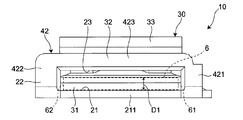
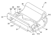
- the disassembled perspective view of the connecting terminal of FIG. The perspective view of the connector of one embodiment of this indication.
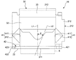
- IV arrow view of FIG. FIG. The perspective view which shows the 1st modification of the intermediate
- middle guide protrusion part of the connector of FIG. The perspective view which shows the 3rd modification of the intermediate
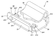
- the perspective view which shows the 2nd modification of the start end guide protrusion part of the connector of FIG. The perspective view which shows the modification of the insertion angle control part of the connector of FIG.
- the connector 10 according to an embodiment of the present disclosure is used in a state of being accommodated in the housing 2 as illustrated in FIGS.
- the connection terminal 1 as an example, the crimp holding portion 3 to which the cable 4 is crimped is formed integrally with the connector 10.
- the connector 10 is a flat terminal that is accommodated in the housing 2 with a terminal insertion opening 23 (described later) facing the opening 5 of the housing 2 and inserted into the housing 2 from the opening 5 of the housing 2. 6 and the connector 10 can be connected.
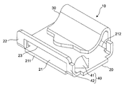
- the connector 10 includes a base 20, an elastic clamping unit 30, and an insertion angle regulating unit 40.
- the connector 10 is made of, for example, a single metal plate having conductivity, and the base 20, the elastic clamping unit 30, and the insertion angle regulating unit 40 are integrally formed.
- the base 20 has a quadrangular shape (see FIG. 5) in plan view along the plate thickness direction (that is, the vertical direction in FIG. 3), and as shown in FIG. 3, the terminal support surface 21 and the terminal insertion opening 23 are provided. And a terminal connection surface 22 provided.
- the terminal support surface 21 constitutes one surface of the base 20 in the plate thickness direction (that is, the upper surface in FIG. 3), and has a first end 211 and a second end 212 that face each other.
- the terminal connection surface 22 is provided at the first end 211 of the terminal support surface 21 and extends in a direction intersecting the terminal connection surface 22.
- the terminal connection surface 22 is provided with a terminal insertion opening 23, and the terminal insertion direction from the first end 211 to the second end 212 of the terminal support surface 21 through the terminal insertion opening 23.
- the flat terminal 6 can be inserted in the direction indicated by the arrow IV, which is the direction in which the flat terminal 6 is inserted into the terminal connection surface 22.
- the flat terminal 6 inserted in the terminal insertion direction from the terminal insertion opening 23 has a terminal support surface 21 formed along the terminal insertion direction so that the lower surface of the flat terminal 6 in FIG. Be guided to.
- the elastic clamping part 30 has the base 31 and the elastic part 32, as shown in FIG.
- the base 31 is connected to the second end 212 of the terminal support surface 21 and extends linearly from the terminal support surface 21 in a direction intersecting the terminal support surface 21.
- the elastic part 32 is disposed so as to face the terminal support surface 21 and cover a part of the terminal support surface in a plan view orthogonal to the terminal support surface 21 (see FIG. 5), and away from the terminal support surface 21. (That is, the upper side of FIG. 3) is configured to be elastically deformable.
- the elastic portion 32 has a gap D ⁇ b> 1 smaller than the plate thickness D ⁇ b> 2 (shown in FIG. 1) of the flat terminal 6 between the terminal support surface 21.
- the elastic portion 32 is elastically deformed in a direction away from the terminal support surface 21 so that the flat terminal 6 is clamped together with the terminal support surface 21. It has become.
- the base portion 31 and the elastic portion 32 are connected by a bending portion 33.
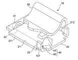
- the insertion angle restricting portion 40 includes a pair of intermediate guide protrusions 41 provided between the first end 211 and the second end 212 of the terminal support surface 21, and the terminal support surface 21.
- the first end portion 211 of the first end guide projection 42 is provided.
- the pair of intermediate guide protrusions 41 is disposed in the vicinity of the start end guide protrusion 42 (that is, in the vicinity of the first end 211).
- the insertion angle restricting portion 40 guides the flat terminal 6 inserted along the terminal support surface 21 from the terminal insertion opening 23 in the terminal inserting direction, and restricts the insertion angle of the flat terminal 6 with respect to the terminal inserting direction. To do.
- the lower surface of the flat terminal 6 is guided by the terminal support surface 21, so that the downward movement is restricted.
- the right side surface of the flat terminal 6 is guided by the intermediate guide protrusion 41 and the first protrusion 421 of the start end guide protrusion portion 42 facing the right side surface of the flat terminal 6, thereby restricting the rightward movement.
- the left side surface of the flat terminal 6 is guided by the intermediate guide protrusion 41 and the second protrusion 422 of the start end guide protrusion portion 42 facing the left side surface of the flat terminal 6, thereby restricting leftward movement. Is done.
- each intermediate guide protrusion 41 includes a guide surface 411 and a support portion 412 that supports the guide surface 411.
- the guide surface 411 has a substantially semicircular shape, intersects the terminal support surface 21 and the terminal connection surface 22, and is a part of the flat terminal 6 inserted from the terminal insertion opening 23.
- the flat terminal 6 is disposed so as to be opposed to the side.
- the guide surface 411 has a height from the terminal support surface 21 close to the plate thickness D2 of the flat terminal 6, and the flat terminal 6 inserted along the terminal support surface 21 from the terminal insertion opening 23. It is comprised so that it can guide reliably in a terminal insertion direction.
- the support portion 412 has a curved outer surface, and as shown in FIG. 5, in plan view along the direction orthogonal to the terminal support surface 21 (that is, the paper surface penetration direction in FIG. 5). It has a triangular shape.
- the support portion 412 extends from the guide surface 411 in a direction away from the flat terminal 6 inserted from the terminal insertion opening 23 in the terminal width direction (that is, the left-right direction in FIG. 5), and supports the guide surface 411. .
- each intermediate guide protrusion 41 can be increased by forming the support 412 in a so-called dome shape. For this reason, for example, even if a force in the plate width direction of the flat terminal 6 is applied to the connector 10, the deformation of the pair of intermediate guide protrusions 41 can be suppressed, so that the pin 20 is clamped between the base 20 and the elastic clamping unit 30. It is possible to suppress the occurrence of a problem (so-called fitting omission) that the flat terminal 6 in a disconnected state comes out of the connector 10.
- the start end guide protrusion 42 is connected to the first protrusion 421 and the second protrusion 422 provided on the first end 211 of the terminal support surface 21, and the first protrusion 421 and the second protrusion 422. Connected portion 423.
- the start end guide projection 42 guides the tip of the flat terminal 6 inserted from the terminal insertion opening 23 in the terminal insertion direction, and regulates the insertion angle of the flat terminal 6 with respect to the terminal insertion direction.
- the first protrusion 421 and the second protrusion 422 extend from the terminal support surface 21 in a direction intersecting the terminal support surface 21 (that is, upward in FIG. 4) and from the terminal insertion opening 23.
- the inserted flat terminals 6 are arranged in parallel on both sides in the terminal width direction.
- the connecting portion 423 extends along the terminal width direction (that is, the left-right direction in FIG. 4), and the end portions (that is, in FIG. 4) of the first protrusion 421 and the second protrusion 422 far from the terminal support surface 21. Connected to the upper end).
- a terminal insertion opening 23 into which the flat terminal 6 can be inserted in the terminal insertion direction is formed in the terminal connection surface 22 with the first protrusion 421, the second protrusion 422, the connection portion 423, and the terminal support surface 21. Yes.
- the terminal connection surface 22 is an outer surface of the first protrusion 421, the second protrusion 422, and the connection portion 423 in the terminal insertion direction.
- the flat terminal 6 is inserted into the connector 10 from the terminal insertion opening 23 along a straight line L2 that forms an insertion angle ⁇ (shown in FIG. 5) with respect to a straight line L1 extending in the terminal insertion direction.
- the operation of the connector 10 when connecting the flat terminal 6 and the connector 10 will be described.
- the flat terminal 6 When the flat terminal 6 is made to approach the terminal insertion opening 23 of the terminal connection surface 22 along the straight line L2, the first side surface 61 (shown in FIG. 4) of the flat terminal 6 in the terminal width direction and the first side Of the two side surfaces 62 (shown in FIG. 4), the tip of the first side surface 61 contacts the first protrusion 421. Thereby, the flat terminal 6 is guided in the direction of the straight line L1 (that is, the terminal insertion direction).
- the tip of the first side surface 61 of the flat terminal 6 extends in a direction perpendicular to the terminal support surface 21.
- the guide surface 411 of the intermediate guide protrusion 41 is located on the same side as the first protrusion 421 with respect to the straight line L1. Thereby, the flat terminal 6 is guided in the direction of the straight line L1 (that is, the terminal insertion direction).
- the flat terminal 6 inserted along the straight line L2 that forms the insertion angle ⁇ with respect to the straight line L1 is connected to the connector 10 by the first protrusion 421 of the start end guide protrusion 42 and the guide surface 411 of the intermediate guide protrusion 41. While being inserted into the connector 10, it is inserted into the connector 10 along the straight line L1.
- the tip of the flat terminal 6 is inserted into the gap D1 between the terminal support surface 21 and the elastic part 32 of the elastic clamping part 30,
- the elastic part 32 is elastically deformed in a direction away from the terminal support surface 21. Due to the elastic force of the elastic part 32, the flat terminal 6 is clamped by the terminal support surface 21 and the elastic clamping part 30 and connected to the connector 10.
- the tip of the flat terminal 6 comes into contact with the base 31 of the elastic clamping portion 30.
- the movement into the connector 10 is completed.
- the movement of the flat terminal 6 in the terminal width direction of the flat terminal 6 is restricted by the first protrusion 421 of the start end guide protrusion 42 and the guide surface 411 of the intermediate guide protrusion 41. That is, since the flat terminal 6 inserted into the connector 10 is supported by the intermediate guide protrusion 41 and the start guide protrusion 42 in the plate width direction, for example, the connector 10 has a flat terminal 6 plate.
- the insertion angle regulating portion 40 that regulates the insertion angle ⁇ of the flat terminal 6 inserted along the terminal support surface 21 from the terminal insertion opening 23 with respect to the terminal insertion direction is provided. Yes. That is, when the insertion of the flat terminal 6 into the terminal insertion opening 23 is started, the insertion angle ⁇ of the flat terminal 6 is regulated by the start guide protrusion 42, and after the flat terminal 6 is inserted into the terminal insertion opening 23.
- the intermediate guide protrusion 41 restricts the insertion angle ⁇ of the flat terminal 6.
- the flat terminal 6 and the connector 10 are The flat terminal 6 can be securely clamped between the terminal support surface 21 and the elastic clamping portion 30 by preventing the connection with the terminal insertion direction obliquely. As a result, high connection reliability can be exhibited.
- the movement of the flat terminal 6 in the terminal width direction of the flat terminal 6 is restricted by the start end guide protrusion 42 and the intermediate guide protrusion 41. Is done. Therefore, for example, even if the cable 4 connected to the connector 10 is pulled and a force in the plate width direction of the flat terminal 6 is applied to the connector 10, the start end guide protrusion 42 and the intermediate guide protrusion 41 The movement of the flat terminal 6 in the plate width direction is restricted, and the connection between the flat terminal 6 and the connector 10 can be prevented from being forcibly released. As a result, high connection reliability can be exhibited.
- the intermediate guide protrusion 41 is disposed in the vicinity of the terminal connection surface 22, the flat terminal 6 inserted into the connector 10 from the terminal insertion opening 23 can be more reliably guided in the terminal insertion direction. .
- the intermediate guide protrusions 41 are arranged on both sides in the terminal width direction of the flat terminal 6 inserted from the terminal insertion opening 23, respectively, and the terminal width of the flat terminal 6 inserted from the terminal insertion opening 23. Since both sides of the direction are guided, the flat terminal 6 is obliquely connected to the connector and the terminal insertion direction regardless of which force is applied to the connector 10 in the plate width direction of the flat terminal 6. Can be prevented.
- the intermediate guide protrusion 41 has a guide surface 411 and a support portion 412 that supports the guide surface 411. Thereby, since the intensity
- the starting end guide projection 42 has a first projection 421, a second projection 422, and a connection portion 423. Thereby, even if any force in the plate width direction of the flat terminal 6 is applied to the connector 10, the flat terminal 6 can be prevented from being obliquely connected to the connector 10 with respect to the terminal insertion direction. .
- start end guide protrusion 42 is formed integrally with the base 20. Thereby, the intensity
- the intermediate guide protrusion is not limited to the intermediate guide protrusion 41 having the semicircular guide surface 411 and the support portion 412 having a curved outer surface.
- an intermediate guide protrusion 41 having a rectangular guide surface 411 and a rectangular support portion 412 in a plan view along a direction orthogonal to the terminal support surface 21 may be used.
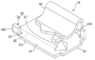
- the intermediate guide protrusions 41 are not limited to the case where the intermediate guide protrusions 41 are arranged on both sides in the terminal width direction with respect to the flat terminals 6 inserted from the terminal insertion openings 23 in the terminal support surface 21, for example, FIG. As shown in FIG. 4, the terminal support surface 21 may be disposed only on one side in the terminal width direction.
- the start end guide protrusion 42 is not limited to the start end guide protrusion 42 having the first protrusion 421, the second protrusion 422, and the connection portion 423.
- it may be the start end guide protrusion 42 having only the first protrusion 421, or the first protrusion 421 and the second protrusion 422 which are not connected to each other as shown in FIG.
- the start end guide protrusion 42 may be provided.
- the terminal connection surface 22 is a virtual surface on the same plane as the outer surface of the first protrusion 421 (and the second protrusion 422) in the terminal insertion direction.
- the insertion angle restricting portion 40 only needs to have at least one of the intermediate guide protrusion 41 and the start guide protrusion 42, and is not limited to having the intermediate guide protrusion 41 and the start guide protrusion 42.
- the insertion angle restricting portion may have only the intermediate guide protrusion or only the start end guide protrusion depending on the design of the connector. In either case, the flat terminal can be securely clamped between the terminal support surface and the elastic clamping portion, and high connection reliability can be exhibited.
- the insertion angle restricting portion 40 includes the intermediate guide protrusion 41 disposed only on one side of the terminal support surface 21 in the terminal width direction and the start end guide protrusion 42 having only the first protrusion 421, FIG. As shown, the intermediate guide protrusion 41 and the first protrusion 421 of the start guide protrusion 42 are diagonal to the flat terminal 6 inserted along the terminal support surface 21 from the terminal insertion opening 23. It is preferable to arrange. By arranging in this way, the intermediate guide projection 41 and the first projection 421 are flat compared to the case where they are arranged on the same side with respect to the flat terminal 6 inserted from the terminal insertion opening 23. It is possible to reliably prevent the mold terminal 6 and the connector 10 from being connected obliquely with respect to the terminal insertion direction.
- the connector 10 includes: A terminal support surface 21 having a first end 211 and a second end 212 that face each other, and a terminal connection surface that is provided at the first end 211 of the terminal support surface 21 and intersects the terminal support surface 21 22 and a terminal 20 provided on the terminal connection surface 22 and having a terminal insertion opening 23 into which the flat terminal 6 can be inserted in the terminal insertion direction from the first end 211 toward the second end 212.
- the base 31 connected to the second end 212 of the terminal support surface 21 and the terminal 31 are arranged so as to face the terminal support surface 21 and elastically deformed in a direction away from the terminal support surface 21 to form the terminal.
- An elastic holding part 30 having an elastic part 32 capable of holding the flat terminal 6 together with the support surface 21;
- the insertion angle ⁇ of the flat terminal 6 is regulated by the insertion angle regulating unit 40. For this reason, even if a force in the plate width direction of the flat terminal 6 is applied to the connector 10 while the flat terminal 6 is being inserted into the connector 10, the flat terminal 6 is connected to the connector 10.
- the flat terminal 6 can be securely clamped between the terminal support surface 21 and the elastic clamping portion 30 by preventing the connection with the terminal insertion direction obliquely. As a result, high connection reliability can be exhibited.
- the connector 10 of the second aspect of the present disclosure includes:
- the insertion angle restricting portion 40 is The terminal insertion direction with respect to the flat terminal 6 provided between the first end 211 and the second end 212 of the terminal support surface 21 and inserted from the terminal insertion opening 23.
- a guide protrusion 41 is provided.
- the flat terminal 6 can be securely clamped between the terminal support surface 21 and the elastic clamping portion 30 by the intermediate guide protrusion 41, and high connection reliability can be exhibited.
- the connector 10 includes:
- the insertion angle restricting portion 40 is At least one of the terminal width directions that intersects the terminal insertion direction with respect to the flat terminal 6 provided at the first end 211 of the terminal support surface 21 and inserted from the terminal insertion opening 23. It has a start end guide protrusion 42 that is disposed and guides one side of the flat terminal 6 inserted from the terminal insertion opening 23 in the terminal insertion direction to regulate the insertion angle ⁇ .
- the flat terminal 6 can be reliably clamped between the terminal support surface 21 and the elastic clamping portion 30 by the start end guide projection 42, and high connection reliability can be exhibited.
- the connector 10 of the fourth aspect of the present disclosure is:
- the insertion angle restricting portion 40 is The terminal insertion direction with respect to the flat terminal 6 provided between the first end 211 and the second end 212 of the terminal support surface 21 and inserted from the terminal insertion opening 23.
- An intermediate for regulating the insertion angle ⁇ by guiding one side of the flat terminal 6 inserted through the terminal insertion opening 23 in the terminal insertion direction and disposed in at least one of the terminal width directions intersecting the terminal A guide protrusion 41; At least one of the terminal width directions that intersects the terminal insertion direction with respect to the flat terminal 6 provided at the first end 211 of the terminal support surface 21 and inserted from the terminal insertion opening 23.
- a leading end guide protrusion 42 that is disposed and guides one side of the flat terminal 6 inserted from the terminal insertion opening 23 in the terminal insertion direction to regulate the insertion angle ⁇ ;
- the start end guide protrusion 42 causes the flat terminal 6 to The insertion angle ⁇ is restricted, and the insertion angle ⁇ of the flat terminal 6 is restricted by the intermediate guide protrusion 41 after the flat terminal 6 is inserted into the terminal insertion opening 23. For this reason, the flat terminal 6 can be reliably clamped by the terminal support surface 21 and the elastic clamping part 30, and high connection reliability can be exhibited.
- the connector 10 includes: The intermediate guide protrusion 41 and the start end guide protrusion 42 are disposed diagonally with respect to the flat terminal 6 inserted along the terminal support surface 21 from the terminal insertion opening 23.
- the intermediate guide protrusion 41 and the start guide protrusion 42 are compared with the connector 10 disposed on the same side with respect to the flat terminal 6 inserted from the terminal insertion opening 23.
- the connector 10 of the fifth aspect it is possible to reliably prevent the flat terminal 6 from being obliquely connected to the connector 10 with respect to the terminal insertion direction.
- the connector 10 of the sixth aspect of the present disclosure is:
- the intermediate guide protrusion 41 is disposed in the vicinity of the terminal insertion opening 23.
- the flat terminal 6 inserted into the connector 10 from the terminal insertion opening 23 can be more reliably guided in the terminal insertion direction.
- the connector 10 according to the seventh aspect of the present disclosure includes:
- the intermediate guide protrusions 41 are respectively arranged on both sides in the terminal width direction with respect to the flat terminal 6 inserted from the terminal insertion opening 23.
- the flat terminal 6 is connected to the connector 10 at an angle with respect to the terminal insertion direction. Can be prevented.
- the connector 10 includes:
- the intermediate guide protrusion 41 is A guide surface 411 that intersects the terminal support surface 21 and the terminal connection surface 22 and can contact the flat terminal 6 inserted from the terminal insertion opening 23;
- a support portion 412 that extends from the guide surface 411 in a direction away from the flat terminal 6 inserted from the terminal insertion opening 23 in the terminal width direction and supports the guide surface 411;
- the strength of the intermediate guide protrusion 41 can be increased, so that the flat terminal 6 inserted into the connector 10 from the terminal insertion opening 23 can be more reliably placed in the terminal insertion direction. I can guide you.
- the connector 10 of the ninth aspect of the present disclosure is:
- the start guide protrusion 42 is Extending in a direction intersecting the terminal support surface 21 from the terminal support surface 21 and arranged in parallel on both sides in the terminal width direction with respect to the flat terminal 6 inserted from the terminal insertion opening 23.
- a connecting portion 423 extending along the terminal width direction and connected to an end of the first protrusion 421 and the second protrusion 422 far from the terminal support surface 21;
- Have The terminal insertion opening 23 is formed by the first protrusion 421, the second protrusion 422, the connection portion 423, and the terminal support surface 21.
- the flat terminal 6 is obliquely connected to the connector 10 and the terminal insertion direction. Can be prevented.
- the connector 10 includes:
- the start guide protrusion 42 is formed integrally with the base 20.
- the strength of the starting end guide projection 42 can be increased, and the flat terminal 6 inserted into the connector 10 from the terminal insertion opening 23 is more reliably guided in the terminal insertion direction. it can.
- the connector of the present disclosure can be used for an air conditioner, for example.
Landscapes
- Details Of Connecting Devices For Male And Female Coupling (AREA)
- Coupling Device And Connection With Printed Circuit (AREA)
Abstract
コネクタが、相互に対向する第1端部および第2端部を有する端子支持面と端子支持面の第1端部に設けられかつ端子支持面に交差する端子接続面と端子接続面に設けられた端子挿入開口部とを有するベースと、端子支持面の第2端部に接続された基部と端子支持面に対向するように配置されている弾性部とを有する弾性挟持部と、端子挿入開口部から端子支持面に沿って挿入された平型端子の端子挿入方向に対する挿入角度を規制する挿入角度規制部と、を備える。
Description
本開示は、平型端子を挿入可能なコネクタに関する。
特許文献1には、板状の平型端子を挿入可能なコネクタと、このコネクタに一体成形されかつ線材を圧着保持する圧着保持部とで構成された接続端子が開示されている。前記接続端子では、コネクタの内部に挿入された平型端子が、その板厚方向でコネクタにより挟持されて、平型端子とコネクタとが接続される。
しかし、前記接続端子では、平型端子は、その板厚方向でのみコネクタにより挟持される。このため、例えば、平型端子をコネクタの内部に挿入している最中に線材が引っ張られて、コネクタに平型端子の板幅方向の力が加えられると、コネクタが平型端子を正常な状態で挟持できず、平型端子と接続部との間の接続信頼性が低くなる場合がある。
本開示は、高い接続信頼性を有するコネクタを提供することを課題とする。
本開示の一態様のコネクタは、
相互に対向する第1端部および第2端部を有する端子支持面と、前記端子支持面の前記第1端部に設けられかつ前記端子支持面に交差する端子接続面と、前記端子接続面に設けられかつ前記第1端部から前記第2端部に向かう端子挿入方向に平型端子を挿入可能な端子挿入開口部とを有するベースと、
前記端子支持面の前記第2端部に接続された基部と、前記端子支持面に対向するように配置されていると共に前記端子支持面から離れる方向に弾性変形して前記端子支持面と共に前記平型端子を挟持可能な弾性部と、を有する弾性挟持部と、
前記端子挿入開口部から前記端子支持面に沿って挿入された前記平型端子の前記端子挿入方向に対する挿入角度を規制する挿入角度規制部と、
を備える。
相互に対向する第1端部および第2端部を有する端子支持面と、前記端子支持面の前記第1端部に設けられかつ前記端子支持面に交差する端子接続面と、前記端子接続面に設けられかつ前記第1端部から前記第2端部に向かう端子挿入方向に平型端子を挿入可能な端子挿入開口部とを有するベースと、
前記端子支持面の前記第2端部に接続された基部と、前記端子支持面に対向するように配置されていると共に前記端子支持面から離れる方向に弾性変形して前記端子支持面と共に前記平型端子を挟持可能な弾性部と、を有する弾性挟持部と、
前記端子挿入開口部から前記端子支持面に沿って挿入された前記平型端子の前記端子挿入方向に対する挿入角度を規制する挿入角度規制部と、
を備える。
前記態様のコネクタによれば、端子挿入開口部から端子支持面に沿って挿入された平型端子の端子挿入方向に対する挿入角度を規制する挿入角度規制部により、平型端子を端子支持面と弾性挟持部とで確実に挟持でき、高い接続信頼性を発揮できる。
以下、本開示の一実施形態を添付図面に従って説明する。なお、以下の説明では、必要に応じて特定の方向あるいは位置を示す用語(例えば、「上」、「下」、「右」、「左」を含む用語)を用いるが、それらの用語の使用は図面を参照した開示の理解を容易にするためであって、それらの用語の意味によって本開示の技術的範囲が限定されるものではない。また、以下の説明は、本質的に例示に過ぎず、本開示、その適用物、あるいは、その用途を制限することを意図するものではない。さらに、図面は模式的なものであり、各寸法の比率等は現実のものとは必ずしも合致していない。
本開示の一実施形態のコネクタ10は、例えば、図1および図2に示すように、ハウジング2に収容された状態で使用され、ハウジング2と共に接続端子1を構成する。この接続端子1では、一例として、ケーブル4が圧着された圧着保持部3が、コネクタ10と一体に形成されている。また、コネクタ10は、後述する端子挿入開口部23がハウジング2の開口部5に対向した状態でハウジング2に収容されて、ハウジング2の開口部5からハウジング2の内部に挿入された平型端子6とコネクタ10とが接続可能になっている。
コネクタ10は、図3に示すように、ベース20と、弾性挟持部30と、挿入角度規制部40とを備える。このコネクタ10は、例えば、導電性を有する1枚の金属板から形成されており、ベース20、弾性挟持部30、および、挿入角度規制部40が一体に構成されている。
ベース20は、板厚方向(すなわち、図3の上下方向)に沿った平面視において四角形状で(図5参照)、図3に示すように、端子支持面21と、端子挿入開口部23が設けられた端子接続面22とを有している。
端子支持面21は、ベース20の板厚方向の一方の面(すなわち、図3の上面)を構成し、相互に対向する第1端部211および第2端部212を有している。
端子接続面22は、端子支持面21の第1端部211に設けられかつ端子接続面22に交差する方向に延びている。この端子接続面22には、端子挿入開口部23が設けられており、この端子挿入開口部23を介して、端子支持面21の第1端部211から第2端部212に向かう端子挿入方向(すなわち、平型端子6の端子接続面22への挿入方向であるIV矢視方向)に、平型端子6を挿入可能になっている。端子挿入開口部23から端子挿入方向に挿入された平型端子6は、端子挿入方向沿いに形成されている端子支持面21により、平型端子6の図3における下側の面が端子挿入方向に案内される。
弾性挟持部30は、図3に示すように、基部31と弾性部32とを有している。
基部31は、端子支持面21の第2端部212に接続されており、端子支持面21から端子支持面21に交差する方向に直線状に延びている。
弾性部32は、端子支持面21に対向し、かつ、端子支持面21に直交する平面視において端子支持面の一部を覆うように配置され(図5参照)、端子支持面21から離れる方向(すなわち、図3の上側)に弾性変形可能に構成されている。この弾性部32は、図4に示すように、端子支持面21との間に、平型端子6の板厚D2(図1に示す)よりも小さい隙間D1を有している。この隙間D1に平型端子6が挿入されると、弾性部32は、端子支持面21から離れる方向に弾性変形して、平型端子6を端子支持面21と共に平型端子6を挟持するようになっている。なお、基部31と弾性部32とは、湾曲部33により接続されている。
挿入角度規制部40は、図3に示すように、端子支持面21の第1端部211と第2端部212との間に設けられた一対の中間ガイド突起部41と、端子支持面21の第1端部211に設けられた始端ガイド突起部42とを有している。一対の中間ガイド突起部41は、始端ガイド突起部42の近傍(すなわち、第1端部211の近傍)に配置されている。この挿入角度規制部40は、端子挿入開口部23から端子支持面21に沿って挿入された平型端子6を端子挿入方向に案内して、平型端子6の端子挿入方向に対する挿入角度を規制する。
例えば、図3において、平型端子6の下側の面は、端子支持面21で案内されることにより、下方向の移動が規制される。また、平型端子6の右側面は、この平型端子6の右側面に対向する中間ガイド突起41および始端ガイド突起部42の第1突起421で案内されることにより、右方向の移動が規制され、平型端子6の左側面は、この平型端子6の左側面に対向する中間ガイド突起41および始端ガイド突起部42の第2突起422で案内されることにより、左方向の移動が規制される。
一対の中間ガイド突起部41は、図3に示すように、端子挿入開口部23から挿入された平型端子6に対して端子幅方向(すなわち、端子挿入方向に交差する方向)の両側にそれぞれ配置されている。各中間ガイド突起部41は、ガイド面411と、このガイド面411を支持する支持部412とを有している。
ガイド面411は、図3に示すように、略半円形状を有し、端子支持面21および端子接続面22に交差し、かつ、端子挿入開口部23から挿入された平型端子6の一側に対向して平型端子6に接触可能に配置されている。このガイド面411は、平型端子6の板厚D2に近い端子支持面21からの高さを有しており、端子挿入開口部23から端子支持面21に沿って挿入された平型端子6を端子挿入方向に確実に案内できるように構成されている。
支持部412は、図3に示すように、外面が湾曲しており、図5に示すように、端子支持面21に直交する方向(すなわち、図5の紙面貫通方向)に沿った平面視において三角形状を有している。この支持部412は、ガイド面411から端子幅方向(すなわち、図5の左右方向)における端子挿入開口部23から挿入された平型端子6から離れる方向に延びてガイド面411を支持している。
このように、支持部412をいわゆるドーム形状に形成することで、各中間ガイド突起部41の強度を高めることができる。このため、例えば、コネクタ10に平型端子6の板幅方向の力が加えられたとしても、一対の中間ガイド突起部41の変形を抑制できるので、ベース20と弾性挟持部30とで挟持された状態の平型端子6がコネクタ10から抜けてしまう不具合(いわゆる嵌合抜け)の発生を抑制できる。
始端ガイド突起部42は、図3に示すように、端子支持面21の第1端部211に設けられた第1突起421および第2突起422と、第1突起421および第2突起422に接続された接続部423とを有している。この始端ガイド突起部42は、端子挿入開口部23から挿入される平型端子6の先端を端子挿入方向に案内して、平型端子6の端子挿入方向に対する挿入角度を規制する。
第1突起421および第2突起422は、図4に示すように、端子支持面21から端子支持面21に交差する方向(すなわち、図4の上向き)に延び、かつ、端子挿入開口部23から挿入された平型端子6に対して端子幅方向の両側のそれぞれに並列に配置されている。
接続部423は、端子幅方向(すなわち、図4の左右方向)に沿って延び、かつ、第1突起421および第2突起422の端子支持面21から遠い方の端部(すなわち、図4の上端部)に接続されている。
第1突起421、第2突起422、接続部423、および、端子支持面21とで、端子挿入方向に平型端子6を挿入可能な端子挿入開口部23が、端子接続面22に形成されている。なお、この実施形態では、端子接続面22は、第1突起421、第2突起422、接続部423の端子挿入方向における外面である。
次に、平型端子6が、端子挿入方向に延びる直線L1に対して挿入角度θ(図5に示す)を成す直線L2に沿って、端子挿入開口部23からコネクタ10の内部に挿入して、平型端子6とコネクタ10とを接続するときのコネクタ10の動作について説明する。
平型端子6を直線L2に沿って端子接続面22の端子挿入開口部23に向かって接近させていくと、平型端子6の端子幅方向の第1側面61(図4に示す)および第2側面62(図4に示す)のうちの第1側面61の先端が、第1突起421に接触する。これにより、平型端子6が、直線L1方向(すなわち、端子挿入方向)に案内される。
端子挿入開口部23から挿入された平型端子6をさらにコネクタ10の内部に向かって移動させると、平型端子6の第1側面61の先端が、端子支持面21に対して直交する方向に沿って見たときに直線L1に対して第1突起421と同じ側に位置している中間ガイド突起部41のガイド面411と接触する。これにより、平型端子6が、直線L1方向(すなわち、端子挿入方向)に案内される。
すなわち、直線L1に対して挿入角度θを成す直線L2に沿って挿入された平型端子6は、始端ガイド突起部42の第1突起421および中間ガイド突起部41のガイド面411によって、コネクタ10の内部に挿入している最中に直線L1に沿ってコネクタ10の内部に挿入される。
なお、平型端子6の挿入し易さを確保するため、端子挿入開口部23の開口縁と平型端子6との間にはある程度の隙間が設けられている。この隙間に起因するガタツキが、平型端子6の端子挿入開口部23への挿入後に中間ガイド突起41で規制される。
さらに、平型端子6をコネクタ10の内部に向かって移動させていくと、平型端子6の先端が端子支持面21と弾性挟持部30の弾性部32との間の隙間D1に挿入され、弾性部32を端子支持面21から離れる方向に弾性変形させる。この弾性部32の弾性力により、平型端子6が、端子支持面21と弾性挟持部30とにより挟持されて、コネクタ10に接続される。
平型端子6とコネクタ10とが接触した状態で、平型端子6をさらにコネクタ10の内部に向かって移動させていくと、平型端子6の先端が弾性挟持部30の基部31と接触して、コネクタ10の内部への移動が終了する。このとき、平型端子6は、始端ガイド突起部42の第1突起421および中間ガイド突起部41のガイド面411によって、平型端子6の端子幅方向への移動が規制されている。すなわち、コネクタ10の内部に挿入された平型端子6が、その板幅方向において、中間ガイド突起部41および始端ガイド突起部42で支持されるので、例えば、コネクタ10に平型端子6の板幅方向の力が加えられたとしても、その加えられた力が中間ガイド突起部41および始端ガイド突起部42に分散される。このため、中間ガイド突起部41および始端ガイド突起部42の変形を抑制できて、ベース20と弾性挟持部30とで挟持された状態の平型端子6がコネクタ10から抜けてしまう不具合(いわゆる嵌合抜け)の発生を抑制できる。
このように、前記コネクタ10によれば、端子挿入開口部23から端子支持面21に沿って挿入された平型端子6の端子挿入方向に対する挿入角度θを規制する挿入角度規制部40を備えている。すなわち、平型端子6の端子挿入開口部23への挿入開始時には、始端ガイド突起部42により平型端子6の挿入角度θが規制され、平型端子6の端子挿入開口部23への挿入後には、中間ガイド突起部41により平型端子6の挿入角度θが規制される。このため、仮に、平型端子6をコネクタ10の内部に挿入している最中にコネクタ10に平型端子6の板幅方向の力が加えられたとしても、平型端子6とコネクタ10が端子挿入方向に対して斜めに接続されるのを防止して、平型端子6を端子支持面21と弾性挟持部30とで確実に挟持できる。その結果、高い接続信頼性を発揮できる。
さらに、平型端子6のコネクタ10の内部への挿入後においても、平型端子6が、始端ガイド突起部42および中間ガイド突起部41によって、平型端子6の端子幅方向への移動が規制される。このため、例えば、コネクタ10に接続されているケーブル4が引っ張られてコネクタ10に平型端子6の板幅方向の力が加えられたとしても、始端ガイド突起部42および中間ガイド突起部41によって、平型端子6の板幅方向への移動が規制され、平型端子6とコネクタ10との接続が強制的に解除されるのを防止できる。その結果、高い接続信頼性を発揮できる。
また、中間ガイド突起部41が、端子接続面22の近傍に配置されているので、端子挿入開口部23からコネクタ10の内部に挿入された平型端子6をより確実に端子挿入方向に案内できる。
また、中間ガイド突起部41が、端子挿入開口部23から挿入された平型端子6の端子幅方向の両側にそれぞれ配置されて、端子挿入開口部23から挿入された平型端子6の端子幅方向の両側を案内するので、コネクタ10に、平型端子6の板幅方向におけるいずれの力が加えられたとしても、平型端子6がコネクタと端子挿入方向に対して斜めに接続されるのを防止できる。
また、中間ガイド突起部41が、ガイド面411と、ガイド面411を支持する支持部412とを有している。これにより、中間ガイド突起部41の強度を高めることができるので、端子挿入開口部23からコネクタ10の内部に挿入された平型端子6をより確実に端子挿入方向に案内できる。
また、始端ガイド突起部42が、第1突起421、第2突起422、および、接続部423を有している。これにより、コネクタ10に、平型端子6の板幅方向におけるいずれの力が加えられたとしても、平型端子6がコネクタ10とが端子挿入方向に対して斜めに接続されるのを防止できる。
また、始端ガイド突起部42が、ベース20と一体に構成されている。これにより、始端ガイド突起部42の強度を高めることができ、端子挿入開口部23からコネクタ10の内部に挿入された平型端子6をより確実に端子挿入方向に案内できる。
なお、前記コネクタ10では、図2に示すように、ベース20の端子幅方向には、圧着保持部3のみが一体に形成されている。このため、端子幅方向における展開長を抑えて、生産性の向上を図ることができる。
中間ガイド突起部は、半円形状のガイド面411と外面が湾曲した支持部412とを有する中間ガイド突起部41に限らない。例えば、図6に示すように、略台形状のガイド面411と、端子支持面21に直交する方向に沿った平面視において矩形状の支持部412とを有する中間ガイド突起部41であってもよい。また、図7に示すように、矩形のガイド面411と、端子支持面21に直交する方向に沿った平面視において矩形状の支持部412とを有する中間ガイド突起部41であってもよい。
また、中間ガイド突起部41は、端子支持面21における端子挿入開口部23から挿入された平型端子6に対して端子幅方向の両側にそれぞれ配置されている場合に限らず、例えば、図8に示すように、端子支持面21の端子幅方向の一方のみに配置してもよい。
始端ガイド突起部は、第1突起421、第2突起422、および、接続部423を有する始端ガイド突起部42に限らない。例えば、図9に示すように、第1突起421のみを有する始端ガイド突起部42であってもよいし、図10に示すように、相互に接続されていない第1突起421および第2突起422を有する始端ガイド突起部42であってもよい。この場合、端子接続面22は、第1突起421(および第2突起422)の端子挿入方向における外面と同一面上の仮想面である。
挿入角度規制部40は、中間ガイド突起部41および始端ガイド突起部42の少なくともいずれかを有していればよく、中間ガイド突起部41および始端ガイド突起部42を有する場合に限らない。すなわち、挿入角度規制部は、コネクタの設計等に応じて、中間ガイド突起部のみを有してもよいし、始端ガイド突起部のみを有してもよい。いずれの場合であっても、平型端子を端子支持面と弾性挟持部とで確実に挟持でき、高い接続信頼性を発揮できる。
なお、挿入角度規制部40が、端子支持面21の端子幅方向の一方のみに配置された中間ガイド突起部41と、第1突起421のみを有する始端ガイド突起部42とを有する場合、図11に示すように、中間ガイド突起部41と始端ガイド突起部42の第1突起421とは、端子挿入開口部23から端子支持面21に沿って挿入された平型端子6に対して対角に配置するのが好ましい。このように配置することで、中間ガイド突起部41と第1突起421とが、端子挿入開口部23から挿入された平型端子6に対して同じ側に配置された場合と比較して、平型端子6がコネクタ10と端子挿入方向に対して斜めに接続されるのを確実に防止できる。
以上、図面を参照して本開示における種々の実施形態を詳細に説明したが、最後に、本開示の種々の態様について説明する。なお、以下の説明では、一例として、参照符号も添えて記載する。
本開示の第1態様のコネクタ10は、
相互に対向する第1端部211および第2端部212を有する端子支持面21と、前記端子支持面21の前記第1端部211に設けられかつ前記端子支持面21に交差する端子接続面22と、前記端子接続面22に設けられかつ前記第1端部211から前記第2端部212に向かう端子挿入方向に平型端子6を挿入可能な端子挿入開口部23とを有するベース20と、
前記端子支持面21の前記第2端部212に接続された基部31と、前記端子支持面21に対向するように配置されていると共に前記端子支持面21から離れる方向に弾性変形して前記端子支持面21と共に前記平型端子6を挟持可能な弾性部32と、を有する弾性挟持部30と、
前記端子挿入開口部23から前記端子支持面21に沿って挿入された前記平型端子6の前記端子挿入方向に対する挿入角度を規制する挿入角度規制部40と、
を備える。
相互に対向する第1端部211および第2端部212を有する端子支持面21と、前記端子支持面21の前記第1端部211に設けられかつ前記端子支持面21に交差する端子接続面22と、前記端子接続面22に設けられかつ前記第1端部211から前記第2端部212に向かう端子挿入方向に平型端子6を挿入可能な端子挿入開口部23とを有するベース20と、
前記端子支持面21の前記第2端部212に接続された基部31と、前記端子支持面21に対向するように配置されていると共に前記端子支持面21から離れる方向に弾性変形して前記端子支持面21と共に前記平型端子6を挟持可能な弾性部32と、を有する弾性挟持部30と、
前記端子挿入開口部23から前記端子支持面21に沿って挿入された前記平型端子6の前記端子挿入方向に対する挿入角度を規制する挿入角度規制部40と、
を備える。
第1態様のコネクタ10によれば、挿入角度規制部40により、平型端子6の挿入角度θが規制される。このため、仮に、平型端子6をコネクタ10の内部に挿入している最中にコネクタ10に平型端子6の板幅方向の力が加えられたとしても、平型端子6がコネクタ10と端子挿入方向に対して斜めに接続されるのを防止して、平型端子6を端子支持面21と弾性挟持部30とで確実に挟持できる。その結果、高い接続信頼性を発揮できる。
本開示の第2態様のコネクタ10は、
前記挿入角度規制部40が、
前記端子支持面21の前記第1端部211と前記第2端部212との間に設けられ、かつ、前記端子挿入開口部23から挿入された前記平型端子6に対して前記端子挿入方向に交差する端子幅方向の少なくとも一方に配置されて、前記端子挿入開口部23から挿入された前記平型端子6の一側を前記端子挿入方向に案内して、前記挿入角度θを規制する中間ガイド突起部41を有する。
前記挿入角度規制部40が、
前記端子支持面21の前記第1端部211と前記第2端部212との間に設けられ、かつ、前記端子挿入開口部23から挿入された前記平型端子6に対して前記端子挿入方向に交差する端子幅方向の少なくとも一方に配置されて、前記端子挿入開口部23から挿入された前記平型端子6の一側を前記端子挿入方向に案内して、前記挿入角度θを規制する中間ガイド突起部41を有する。
第2態様のコネクタ10によれば、中間ガイド突起部41により、平型端子6を端子支持面21と弾性挟持部30とで確実に挟持でき、高い接続信頼性を発揮できる。
本開示の第3態様のコネクタ10は、
前記挿入角度規制部40が、
前記端子支持面21の前記第1端部211に設けられ、かつ、前記端子挿入開口部23から挿入される前記平型端子6に対して前記端子挿入方向に交差する端子幅方向の少なくとも一方に配置されて、前記端子挿入開口部23から挿入された前記平型端子6の一側を前記端子挿入方向に案内して、前記挿入角度θを規制する始端ガイド突起部42を有する。
前記挿入角度規制部40が、
前記端子支持面21の前記第1端部211に設けられ、かつ、前記端子挿入開口部23から挿入される前記平型端子6に対して前記端子挿入方向に交差する端子幅方向の少なくとも一方に配置されて、前記端子挿入開口部23から挿入された前記平型端子6の一側を前記端子挿入方向に案内して、前記挿入角度θを規制する始端ガイド突起部42を有する。
第3態様のコネクタ10によれば、始端ガイド突起部42により、平型端子6を端子支持面21と弾性挟持部30とで確実に挟持でき、高い接続信頼性を発揮できる。
本開示の第4態様のコネクタ10は、
前記挿入角度規制部40が、
前記端子支持面21の前記第1端部211と前記第2端部212との間に設けられ、かつ、前記端子挿入開口部23から挿入された前記平型端子6に対して前記端子挿入方向に交差する端子幅方向の少なくとも一方に配置されて、前記端子挿入開口部23から挿入された前記平型端子6の一側を前記端子挿入方向に案内して、前記挿入角度θを規制する中間ガイド突起部41と、
前記端子支持面21の前記第1端部211に設けられ、かつ、前記端子挿入開口部23から挿入される前記平型端子6に対して前記端子挿入方向に交差する端子幅方向の少なくとも一方に配置されて、前記端子挿入開口部23から挿入された前記平型端子6の一側を前記端子挿入方向に案内して、前記挿入角度θを規制する始端ガイド突起部42と、
を有する。
前記挿入角度規制部40が、
前記端子支持面21の前記第1端部211と前記第2端部212との間に設けられ、かつ、前記端子挿入開口部23から挿入された前記平型端子6に対して前記端子挿入方向に交差する端子幅方向の少なくとも一方に配置されて、前記端子挿入開口部23から挿入された前記平型端子6の一側を前記端子挿入方向に案内して、前記挿入角度θを規制する中間ガイド突起部41と、
前記端子支持面21の前記第1端部211に設けられ、かつ、前記端子挿入開口部23から挿入される前記平型端子6に対して前記端子挿入方向に交差する端子幅方向の少なくとも一方に配置されて、前記端子挿入開口部23から挿入された前記平型端子6の一側を前記端子挿入方向に案内して、前記挿入角度θを規制する始端ガイド突起部42と、
を有する。
第4態様のコネクタ10によれば、中間ガイド突起部41および始端ガイド突起部42により、平型端子6の端子挿入開口部23への挿入開始時には、始端ガイド突起部42により平型端子6の挿入角度θが規制され、平型端子6の端子挿入開口部23への挿入後には、中間ガイド突起部41により平型端子6の挿入角度θが規制される。このため、平型端子6を端子支持面21と弾性挟持部30とで確実に挟持でき、高い接続信頼性を発揮できる。
本開示の第5態様のコネクタ10は、
前記中間ガイド突起部41と前記始端ガイド突起部42とが、前記端子挿入開口部23から前記端子支持面21に沿って挿入された前記平型端子6に対して対角に配置されている。
前記中間ガイド突起部41と前記始端ガイド突起部42とが、前記端子挿入開口部23から前記端子支持面21に沿って挿入された前記平型端子6に対して対角に配置されている。
第5態様のコネクタ10によれば、中間ガイド突起部41と始端ガイド突起部42とが、端子挿入開口部23から挿入された平型端子6に対して同じ側に配置されたコネクタ10と比較して、平型端子6がコネクタ10と端子挿入方向に対して斜めに接続されるのを確実に防止できる。
本開示の第6態様のコネクタ10は、
前記中間ガイド突起部41が、前記端子挿入開口部23の近傍に配置されている。
前記中間ガイド突起部41が、前記端子挿入開口部23の近傍に配置されている。
第6態様のコネクタ10によれば、端子挿入開口部23からコネクタ10の内部に挿入された平型端子6をより確実に端子挿入方向に案内できる。
本開示の第7態様のコネクタ10は、
前記中間ガイド突起部41が、前記端子挿入開口部23から挿入された前記平型端子6に対して前記端子幅方向の両側にそれぞれ配置されている。
前記中間ガイド突起部41が、前記端子挿入開口部23から挿入された前記平型端子6に対して前記端子幅方向の両側にそれぞれ配置されている。
第7態様のコネクタ10によれば、コネクタ10に、平型端子6の板幅方向におけるいずれの力が加えられたとしても、平型端子6がコネクタ10と端子挿入方向に対して斜めに接続されるのを防止できる。
本開示の第8態様のコネクタ10は、
前記中間ガイド突起部41が、
前記端子支持面21および前記端子接続面22に交差しかつ前記端子挿入開口部23から挿入された前記平型端子6に接触可能なガイド面411と、
前記ガイド面411から前記端子幅方向における前記端子挿入開口部23から挿入された前記平型端子6から離れる方向に延びて前記ガイド面411を支持する支持部412と、
を有する。
前記中間ガイド突起部41が、
前記端子支持面21および前記端子接続面22に交差しかつ前記端子挿入開口部23から挿入された前記平型端子6に接触可能なガイド面411と、
前記ガイド面411から前記端子幅方向における前記端子挿入開口部23から挿入された前記平型端子6から離れる方向に延びて前記ガイド面411を支持する支持部412と、
を有する。
第8態様のコネクタ10によれば、中間ガイド突起部41の強度を高めることができるので、端子挿入開口部23からコネクタ10の内部に挿入された平型端子6をより確実に端子挿入方向に案内できる。
本開示の第9態様のコネクタ10は、
前記始端ガイド突起部42が、
前記端子支持面21から前記端子支持面21に交差する方向に延びかつ前記端子挿入開口部23から挿入された前記平型端子6に対して前記端子幅方向の両側のそれぞれに並列に配置された第1突起421および第2突起422と、
前記端子幅方向に沿って延びかつ前記第1突起421および前記第2突起422の前記端子支持面21から遠い方の端部に接続されている接続部423と、
を有し、
前記第1突起421、前記第2突起422、前記接続部423、および、前記端子支持面21とで、前記端子挿入開口部23が形成されている。
前記始端ガイド突起部42が、
前記端子支持面21から前記端子支持面21に交差する方向に延びかつ前記端子挿入開口部23から挿入された前記平型端子6に対して前記端子幅方向の両側のそれぞれに並列に配置された第1突起421および第2突起422と、
前記端子幅方向に沿って延びかつ前記第1突起421および前記第2突起422の前記端子支持面21から遠い方の端部に接続されている接続部423と、
を有し、
前記第1突起421、前記第2突起422、前記接続部423、および、前記端子支持面21とで、前記端子挿入開口部23が形成されている。
第9態様のコネクタ10によれば、コネクタ10に、平型端子6の板幅方向におけるいずれの力が加えられたとしても、平型端子6がコネクタ10と端子挿入方向に対して斜めに接続されるのを防止できる。
本開示の第10態様のコネクタ10は、
前記始端ガイド突起部42が前記ベース20と一体に構成されている。
前記始端ガイド突起部42が前記ベース20と一体に構成されている。
第10態様のコネクタ10によれば、始端ガイド突起部42の強度を高めることができ、端子挿入開口部23からコネクタ10の内部に挿入された平型端子6をより確実に端子挿入方向に案内できる。
なお、前記様々な実施形態または変形例のうちの任意の実施形態または変形例を適宜組み合わせることにより、それぞれの有する効果を奏するようにすることができる。また、実施形態同士の組み合わせまたは実施例同士の組み合わせまたは実施形態と実施例との組み合わせが可能であると共に、異なる実施形態または実施例の中の特徴同士の組み合わせも可能である。
本開示は、添付図面を参照しながら好ましい実施形態に関連して充分に記載されているが、この技術の熟練した人々にとっては種々の変形や修正は明白である。そのような変形や修正は、添付した請求の範囲による本開示の範囲から外れない限りにおいて、その中に含まれると理解されるべきである。
本開示のコネクタは、例えば、空調機に用いることができる。
1 接続端子
2 ハウジング
3 圧着保持部
4 ケーブル
5 開口部
6 平型端子
10 コネクタ
20 ベース
21 端子支持面
211 第1端部
212 第2端部
22 端子接続面
23 端子挿入開口部
30 弾性挟持部
31 基部
32 弾性部
33 湾曲部
40 挿入角度規制部
41 中間ガイド突起部
411 ガイド面
412 支持部
42 始端ガイド突起部
421 第1突起
422 第2突起
423 接続部
D1 隙間
D2 板厚
L1、L2 直線
θ 挿入角度
2 ハウジング
3 圧着保持部
4 ケーブル
5 開口部
6 平型端子
10 コネクタ
20 ベース
21 端子支持面
211 第1端部
212 第2端部
22 端子接続面
23 端子挿入開口部
30 弾性挟持部
31 基部
32 弾性部
33 湾曲部
40 挿入角度規制部
41 中間ガイド突起部
411 ガイド面
412 支持部
42 始端ガイド突起部
421 第1突起
422 第2突起
423 接続部
D1 隙間
D2 板厚
L1、L2 直線
θ 挿入角度
Claims (10)
- 相互に対向する第1端部および第2端部を有する端子支持面と、前記端子支持面の前記第1端部に設けられかつ前記端子支持面に交差する端子接続面と、前記端子接続面に設けられかつ前記第1端部から前記第2端部に向かう端子挿入方向に平型端子を挿入可能な端子挿入開口部とを有するベースと、
前記端子支持面の前記第2端部に接続された基部と、前記端子支持面に対向するように配置されていると共に前記端子支持面から離れる方向に弾性変形して前記端子支持面と共に前記平型端子を挟持可能な弾性部とを有する弾性挟持部と、
前記端子挿入開口部から前記端子支持面に沿って挿入された前記平型端子の前記端子挿入方向に対する挿入角度を規制する挿入角度規制部と、
を備える、コネクタ。 - 前記挿入角度規制部が、
前記端子支持面の前記第1端部と前記第2端部との間に設けられ、かつ、前記端子挿入開口部から挿入された前記平型端子に対して前記端子挿入方向に交差する端子幅方向の少なくとも一方に配置されて、前記端子挿入開口部から挿入された前記平型端子の一側を前記端子挿入方向に案内して、前記挿入角度を規制する中間ガイド突起部を有する、請求項1に記載のコネクタ。 - 前記挿入角度規制部が、
前記端子支持面の前記第1端部に設けられ、かつ、前記端子挿入開口部から挿入される前記平型端子に対して前記端子挿入方向に交差する端子幅方向の少なくとも一方に配置されて、前記端子挿入開口部から挿入された前記平型端子の一側を前記端子挿入方向に案内して、前記挿入角度を規制する始端ガイド突起部を有する、請求項1に記載のコネクタ。 - 前記挿入角度規制部が、
前記端子支持面の前記第1端部と前記第2端部との間に設けられ、かつ、前記端子挿入開口部から挿入された前記平型端子に対して前記端子挿入方向に交差する端子幅方向の少なくとも一方に配置されて、前記端子挿入開口部から挿入された前記平型端子の一側を前記端子挿入方向に案内して、前記挿入角度を規制する中間ガイド突起部と、
前記端子支持面の前記第1端部に設けられ、かつ、前記端子挿入開口部から挿入される前記平型端子に対して前記端子挿入方向に交差する端子幅方向の少なくとも一方に配置されて、前記端子挿入開口部から挿入された前記平型端子の一側を前記端子挿入方向に案内して、前記挿入角度を規制する始端ガイド突起部と、
を有する、請求項1に記載のコネクタ。 - 前記中間ガイド突起部と前記始端ガイド突起部とが、前記端子挿入開口部から前記端子支持面に沿って挿入された前記平型端子に対して対角に配置されている、請求項4に記載のコネクタ。
- 前記中間ガイド突起部が、前記端子挿入開口部の近傍に配置されている、請求項2、4および5のいずれか1つに記載のコネクタ。
- 前記中間ガイド突起部が、前記端子挿入開口部から挿入された前記平型端子に対して前記端子幅方向の両側にそれぞれ配置されている、請求項2および4から6のいずれか1つに記載のコネクタ。
- 前記中間ガイド突起部が、
前記端子支持面および前記端子接続面に交差しかつ前記端子挿入開口部から挿入された前記平型端子に接触可能なガイド面と、
前記ガイド面から前記端子幅方向における前記端子挿入開口部から挿入された前記平型端子から離れる方向に延びて前記ガイド面を支持する支持部と、
を有する、請求項2および4から7のいずれか1つに記載のコネクタ。 - 前記始端ガイド突起部が、
前記端子支持面から前記端子支持面に交差する方向に延びかつ前記端子挿入開口部から挿入された前記平型端子に対して前記端子幅方向の両側のそれぞれに並列に配置された第1突起および第2突起と、
前記端子幅方向に沿って延びかつ前記第1突起および前記第2突起の前記端子支持面から遠い方の端部に接続されている接続部と、
を有し、
前記第1突起、前記第2突起、前記接続部、および、前記端子支持面とで、前記端子挿入開口部が形成されている、請求項3から5のいずれか1つに記載のコネクタ。 - 前記始端ガイド突起部が前記ベースと一体に構成されている、請求項3から5および9のいずれか1つに記載のコネクタ。
Applications Claiming Priority (2)
| Application Number | Priority Date | Filing Date | Title |
|---|---|---|---|
| JP2017050232A JP2018156734A (ja) | 2017-03-15 | 2017-03-15 | コネクタ |
| JP2017-050232 | 2017-03-15 |
Publications (1)
| Publication Number | Publication Date |
|---|---|
| WO2018168128A1 true WO2018168128A1 (ja) | 2018-09-20 |
Family
ID=63522052
Family Applications (1)
| Application Number | Title | Priority Date | Filing Date |
|---|---|---|---|
| PCT/JP2017/044719 Ceased WO2018168128A1 (ja) | 2017-03-15 | 2017-12-13 | コネクタ |
Country Status (2)
| Country | Link |
|---|---|
| JP (1) | JP2018156734A (ja) |
| WO (1) | WO2018168128A1 (ja) |
Families Citing this family (1)
| Publication number | Priority date | Publication date | Assignee | Title |
|---|---|---|---|---|
| JP7590764B2 (ja) | 2021-02-10 | 2024-11-27 | 日本圧着端子製造株式会社 | 接続端子 |
Citations (4)
| Publication number | Priority date | Publication date | Assignee | Title |
|---|---|---|---|---|
| US3097906A (en) * | 1960-05-26 | 1963-07-16 | Amp Inc | Electrical connector |
| US5709574A (en) * | 1996-08-30 | 1998-01-20 | Autosplice Systems Inc. | Surface-mountable socket connector |
| US20130072870A1 (en) * | 2011-09-21 | 2013-03-21 | Fresenius Medical Care Deutschland Gmbh | Terminal clamp for a moisture sensor for monitoring a vascular access |
| JP2015141794A (ja) * | 2014-01-28 | 2015-08-03 | オムロン株式会社 | コネクタ |
-
2017
- 2017-03-15 JP JP2017050232A patent/JP2018156734A/ja active Pending
- 2017-12-13 WO PCT/JP2017/044719 patent/WO2018168128A1/ja not_active Ceased
Patent Citations (5)
| Publication number | Priority date | Publication date | Assignee | Title |
|---|---|---|---|---|
| US3097906A (en) * | 1960-05-26 | 1963-07-16 | Amp Inc | Electrical connector |
| JPS3820086B1 (ja) * | 1960-05-26 | 1963-09-30 | ||
| US5709574A (en) * | 1996-08-30 | 1998-01-20 | Autosplice Systems Inc. | Surface-mountable socket connector |
| US20130072870A1 (en) * | 2011-09-21 | 2013-03-21 | Fresenius Medical Care Deutschland Gmbh | Terminal clamp for a moisture sensor for monitoring a vascular access |
| JP2015141794A (ja) * | 2014-01-28 | 2015-08-03 | オムロン株式会社 | コネクタ |
Also Published As
| Publication number | Publication date |
|---|---|
| JP2018156734A (ja) | 2018-10-04 |
Similar Documents
| Publication | Publication Date | Title |
|---|---|---|
| JP4429246B2 (ja) | 平型ケーブル用電気コネクタ | |
| JP6969643B2 (ja) | 端子モジュール、端子モジュールユニット、及びコネクタ | |
| KR102364124B1 (ko) | 단자대 | |
| US9985371B1 (en) | Connector | |
| US10103460B2 (en) | Terminal block | |
| JP2013098088A (ja) | 雌型端子金具 | |
| CN101202397A (zh) | 同轴电连接器 | |
| JP6603264B2 (ja) | 端子台 | |
| JP2019079674A (ja) | コネクタ端子およびコネクタ | |
| JP2018037150A (ja) | 回路基板用電気コネクタ | |
| JP2015076207A (ja) | コネクタ | |
| US20180013212A1 (en) | Terminal with reduced normal force | |
| JP2018200777A (ja) | 端子モジュール | |
| CN116888828A (zh) | 端子模块及连接器 | |
| JP5835340B2 (ja) | 板状端子 | |
| CN205122836U (zh) | 连接端子及连接组件 | |
| WO2017163858A1 (ja) | 端子モジュール | |
| EP2704268A1 (en) | Connector terminal | |
| JP2018156734A (ja) | コネクタ | |
| JP5274635B2 (ja) | コネクタ | |
| JP6247017B2 (ja) | 圧接コネクタ及びこれに用いられるハウジング | |
| JP7068896B2 (ja) | 端子押し付け構造を有するコネクタ装置 | |
| CN204391319U (zh) | 轨道型电联接端子的导电接线结构 | |
| JP6279967B2 (ja) | 接続端子 | |
| KR102853847B1 (ko) | 인서트 성형된 단자를 구비하는 커넥터 |
Legal Events
| Date | Code | Title | Description |
|---|---|---|---|
| 121 | Ep: the epo has been informed by wipo that ep was designated in this application |
Ref document number: 17900676 Country of ref document: EP Kind code of ref document: A1 |
|
| NENP | Non-entry into the national phase |
Ref country code: DE |
|
| 122 | Ep: pct application non-entry in european phase |
Ref document number: 17900676 Country of ref document: EP Kind code of ref document: A1 |