WO2018164942A1 - Method for rendering color images - Google Patents
Method for rendering color images Download PDFInfo
- Publication number
- WO2018164942A1 WO2018164942A1 PCT/US2018/020588 US2018020588W WO2018164942A1 WO 2018164942 A1 WO2018164942 A1 WO 2018164942A1 US 2018020588 W US2018020588 W US 2018020588W WO 2018164942 A1 WO2018164942 A1 WO 2018164942A1
- Authority
- WO
- WIPO (PCT)
- Prior art keywords
- color
- gamut
- para
- display
- electro
- Prior art date
Links
- 238000009877 rendering Methods 0.000 title claims abstract description 84
- 238000000034 method Methods 0.000 title claims description 201
- 239000003086 colorant Substances 0.000 claims abstract description 111
- 239000002245 particle Substances 0.000 claims description 95
- 230000007613 environmental effect Effects 0.000 claims description 37
- 230000002950 deficient Effects 0.000 claims description 32
- 238000013507 mapping Methods 0.000 claims description 32
- 238000003032 molecular docking Methods 0.000 claims description 23
- 238000012545 processing Methods 0.000 claims description 23
- 238000012937 correction Methods 0.000 claims description 18
- 239000012530 fluid Substances 0.000 claims description 14
- 230000004048 modification Effects 0.000 claims description 13
- 238000012986 modification Methods 0.000 claims description 13
- 239000012769 display material Substances 0.000 claims description 11
- 238000005259 measurement Methods 0.000 claims description 9
- 230000005684 electric field Effects 0.000 claims description 8
- 238000004891 communication Methods 0.000 claims description 7
- GNFTZDOKVXKIBK-UHFFFAOYSA-N 3-(2-methoxyethoxy)benzohydrazide Chemical compound COCCOC1=CC=CC(C(=O)NN)=C1 GNFTZDOKVXKIBK-UHFFFAOYSA-N 0.000 claims description 6
- 238000012360 testing method Methods 0.000 claims description 6
- FGUUSXIOTUKUDN-IBGZPJMESA-N C1(=CC=CC=C1)N1C2=C(NC([C@H](C1)NC=1OC(=NN=1)C1=CC=CC=C1)=O)C=CC=C2 Chemical compound C1(=CC=CC=C1)N1C2=C(NC([C@H](C1)NC=1OC(=NN=1)C1=CC=CC=C1)=O)C=CC=C2 FGUUSXIOTUKUDN-IBGZPJMESA-N 0.000 claims description 5
- 230000001186 cumulative effect Effects 0.000 claims description 5
- 230000008878 coupling Effects 0.000 claims description 3
- 238000010168 coupling process Methods 0.000 claims description 3
- 238000005859 coupling reaction Methods 0.000 claims description 3
- 238000012804 iterative process Methods 0.000 abstract 1
- 238000009792 diffusion process Methods 0.000 description 22
- 230000000694 effects Effects 0.000 description 20
- 230000008569 process Effects 0.000 description 17
- 230000007547 defect Effects 0.000 description 16
- 239000000049 pigment Substances 0.000 description 15
- 230000003993 interaction Effects 0.000 description 11
- 239000013598 vector Substances 0.000 description 11
- 238000013459 approach Methods 0.000 description 10
- 238000004364 calculation method Methods 0.000 description 10
- 238000013139 quantization Methods 0.000 description 10
- 238000010586 diagram Methods 0.000 description 7
- 238000003384 imaging method Methods 0.000 description 7
- 230000006978 adaptation Effects 0.000 description 6
- 230000000996 additive effect Effects 0.000 description 6
- 238000000149 argon plasma sintering Methods 0.000 description 6
- 230000008901 benefit Effects 0.000 description 6
- 230000008859 change Effects 0.000 description 6
- 238000005516 engineering process Methods 0.000 description 6
- 230000006872 improvement Effects 0.000 description 6
- 230000003287 optical effect Effects 0.000 description 6
- 239000000654 additive Substances 0.000 description 5
- 238000004519 manufacturing process Methods 0.000 description 5
- 239000011159 matrix material Substances 0.000 description 5
- 230000009466 transformation Effects 0.000 description 5
- 230000001419 dependent effect Effects 0.000 description 4
- 230000006870 function Effects 0.000 description 4
- 238000009499 grossing Methods 0.000 description 4
- 238000002156 mixing Methods 0.000 description 4
- 238000005192 partition Methods 0.000 description 4
- 238000007639 printing Methods 0.000 description 4
- 230000000007 visual effect Effects 0.000 description 4
- 239000012463 white pigment Substances 0.000 description 4
- 238000011109 contamination Methods 0.000 description 3
- 230000002829 reductive effect Effects 0.000 description 3
- 238000005070 sampling Methods 0.000 description 3
- 239000007787 solid Substances 0.000 description 3
- 238000003860 storage Methods 0.000 description 3
- 238000004220 aggregation Methods 0.000 description 2
- 230000004888 barrier function Effects 0.000 description 2
- 230000001364 causal effect Effects 0.000 description 2
- 230000001788 irregular Effects 0.000 description 2
- 239000007788 liquid Substances 0.000 description 2
- 230000037230 mobility Effects 0.000 description 2
- 230000007935 neutral effect Effects 0.000 description 2
- 229920006395 saturated elastomer Polymers 0.000 description 2
- 230000035807 sensation Effects 0.000 description 2
- 238000001228 spectrum Methods 0.000 description 2
- 230000007704 transition Effects 0.000 description 2
- 239000001052 yellow pigment Substances 0.000 description 2
- 241001270131 Agaricus moelleri Species 0.000 description 1
- 241000428352 Amma Species 0.000 description 1
- 241000237509 Patinopecten sp. Species 0.000 description 1
- 238000009825 accumulation Methods 0.000 description 1
- 230000002776 aggregation Effects 0.000 description 1
- 230000006399 behavior Effects 0.000 description 1
- 230000005540 biological transmission Effects 0.000 description 1
- 238000005282 brightening Methods 0.000 description 1
- 230000001010 compromised effect Effects 0.000 description 1
- 239000012141 concentrate Substances 0.000 description 1
- 239000000470 constituent Substances 0.000 description 1
- 238000010276 construction Methods 0.000 description 1
- 238000013500 data storage Methods 0.000 description 1
- 238000000354 decomposition reaction Methods 0.000 description 1
- 230000002939 deleterious effect Effects 0.000 description 1
- 230000003292 diminished effect Effects 0.000 description 1
- 238000009826 distribution Methods 0.000 description 1
- 230000001747 exhibiting effect Effects 0.000 description 1
- 229910052739 hydrogen Inorganic materials 0.000 description 1
- 239000001257 hydrogen Substances 0.000 description 1
- 238000005286 illumination Methods 0.000 description 1
- 230000031700 light absorption Effects 0.000 description 1
- 230000000670 limiting effect Effects 0.000 description 1
- 238000012886 linear function Methods 0.000 description 1
- 239000004973 liquid crystal related substance Substances 0.000 description 1
- 238000007726 management method Methods 0.000 description 1
- 230000000873 masking effect Effects 0.000 description 1
- 239000000463 material Substances 0.000 description 1
- 230000007246 mechanism Effects 0.000 description 1
- 230000001404 mediated effect Effects 0.000 description 1
- 239000000203 mixture Substances 0.000 description 1
- 230000005404 monopole Effects 0.000 description 1
- 230000006855 networking Effects 0.000 description 1
- 230000003121 nonmonotonic effect Effects 0.000 description 1
- 238000001208 nuclear magnetic resonance pulse sequence Methods 0.000 description 1
- 230000035699 permeability Effects 0.000 description 1
- 229920000642 polymer Polymers 0.000 description 1
- 238000003672 processing method Methods 0.000 description 1
- 230000001902 propagating effect Effects 0.000 description 1
- 230000008439 repair process Effects 0.000 description 1
- 230000004044 response Effects 0.000 description 1
- 230000002441 reversible effect Effects 0.000 description 1
- 238000012552 review Methods 0.000 description 1
- 235000020637 scallop Nutrition 0.000 description 1
- 238000010187 selection method Methods 0.000 description 1
- 230000003595 spectral effect Effects 0.000 description 1
- 230000006641 stabilisation Effects 0.000 description 1
- 238000011105 stabilization Methods 0.000 description 1
- 238000004381 surface treatment Methods 0.000 description 1
- 239000010409 thin film Substances 0.000 description 1
- 238000012546 transfer Methods 0.000 description 1
- 238000000844 transformation Methods 0.000 description 1
Classifications
-
- G—PHYSICS
- G09—EDUCATION; CRYPTOGRAPHY; DISPLAY; ADVERTISING; SEALS
- G09G—ARRANGEMENTS OR CIRCUITS FOR CONTROL OF INDICATING DEVICES USING STATIC MEANS TO PRESENT VARIABLE INFORMATION
- G09G5/00—Control arrangements or circuits for visual indicators common to cathode-ray tube indicators and other visual indicators
- G09G5/02—Control arrangements or circuits for visual indicators common to cathode-ray tube indicators and other visual indicators characterised by the way in which colour is displayed
- G09G5/06—Control arrangements or circuits for visual indicators common to cathode-ray tube indicators and other visual indicators characterised by the way in which colour is displayed using colour palettes, e.g. look-up tables
-
- G—PHYSICS
- G09—EDUCATION; CRYPTOGRAPHY; DISPLAY; ADVERTISING; SEALS
- G09G—ARRANGEMENTS OR CIRCUITS FOR CONTROL OF INDICATING DEVICES USING STATIC MEANS TO PRESENT VARIABLE INFORMATION
- G09G3/00—Control arrangements or circuits, of interest only in connection with visual indicators other than cathode-ray tubes
- G09G3/20—Control arrangements or circuits, of interest only in connection with visual indicators other than cathode-ray tubes for presentation of an assembly of a number of characters, e.g. a page, by composing the assembly by combination of individual elements arranged in a matrix no fixed position being assigned to or needed to be assigned to the individual characters or partial characters
- G09G3/2003—Display of colours
-
- G—PHYSICS
- G09—EDUCATION; CRYPTOGRAPHY; DISPLAY; ADVERTISING; SEALS
- G09G—ARRANGEMENTS OR CIRCUITS FOR CONTROL OF INDICATING DEVICES USING STATIC MEANS TO PRESENT VARIABLE INFORMATION
- G09G3/00—Control arrangements or circuits, of interest only in connection with visual indicators other than cathode-ray tubes
- G09G3/20—Control arrangements or circuits, of interest only in connection with visual indicators other than cathode-ray tubes for presentation of an assembly of a number of characters, e.g. a page, by composing the assembly by combination of individual elements arranged in a matrix no fixed position being assigned to or needed to be assigned to the individual characters or partial characters
- G09G3/2007—Display of intermediate tones
- G09G3/2059—Display of intermediate tones using error diffusion
-
- G—PHYSICS
- G09—EDUCATION; CRYPTOGRAPHY; DISPLAY; ADVERTISING; SEALS
- G09G—ARRANGEMENTS OR CIRCUITS FOR CONTROL OF INDICATING DEVICES USING STATIC MEANS TO PRESENT VARIABLE INFORMATION
- G09G3/00—Control arrangements or circuits, of interest only in connection with visual indicators other than cathode-ray tubes
- G09G3/20—Control arrangements or circuits, of interest only in connection with visual indicators other than cathode-ray tubes for presentation of an assembly of a number of characters, e.g. a page, by composing the assembly by combination of individual elements arranged in a matrix no fixed position being assigned to or needed to be assigned to the individual characters or partial characters
- G09G3/34—Control arrangements or circuits, of interest only in connection with visual indicators other than cathode-ray tubes for presentation of an assembly of a number of characters, e.g. a page, by composing the assembly by combination of individual elements arranged in a matrix no fixed position being assigned to or needed to be assigned to the individual characters or partial characters by control of light from an independent source
- G09G3/3433—Control arrangements or circuits, of interest only in connection with visual indicators other than cathode-ray tubes for presentation of an assembly of a number of characters, e.g. a page, by composing the assembly by combination of individual elements arranged in a matrix no fixed position being assigned to or needed to be assigned to the individual characters or partial characters by control of light from an independent source using light modulating elements actuated by an electric field and being other than liquid crystal devices and electrochromic devices
- G09G3/344—Control arrangements or circuits, of interest only in connection with visual indicators other than cathode-ray tubes for presentation of an assembly of a number of characters, e.g. a page, by composing the assembly by combination of individual elements arranged in a matrix no fixed position being assigned to or needed to be assigned to the individual characters or partial characters by control of light from an independent source using light modulating elements actuated by an electric field and being other than liquid crystal devices and electrochromic devices based on particles moving in a fluid or in a gas, e.g. electrophoretic devices
-
- G—PHYSICS
- G09—EDUCATION; CRYPTOGRAPHY; DISPLAY; ADVERTISING; SEALS
- G09G—ARRANGEMENTS OR CIRCUITS FOR CONTROL OF INDICATING DEVICES USING STATIC MEANS TO PRESENT VARIABLE INFORMATION
- G09G3/00—Control arrangements or circuits, of interest only in connection with visual indicators other than cathode-ray tubes
- G09G3/20—Control arrangements or circuits, of interest only in connection with visual indicators other than cathode-ray tubes for presentation of an assembly of a number of characters, e.g. a page, by composing the assembly by combination of individual elements arranged in a matrix no fixed position being assigned to or needed to be assigned to the individual characters or partial characters
- G09G3/34—Control arrangements or circuits, of interest only in connection with visual indicators other than cathode-ray tubes for presentation of an assembly of a number of characters, e.g. a page, by composing the assembly by combination of individual elements arranged in a matrix no fixed position being assigned to or needed to be assigned to the individual characters or partial characters by control of light from an independent source
- G09G3/38—Control arrangements or circuits, of interest only in connection with visual indicators other than cathode-ray tubes for presentation of an assembly of a number of characters, e.g. a page, by composing the assembly by combination of individual elements arranged in a matrix no fixed position being assigned to or needed to be assigned to the individual characters or partial characters by control of light from an independent source using electrochromic devices
-
- G—PHYSICS
- G09—EDUCATION; CRYPTOGRAPHY; DISPLAY; ADVERTISING; SEALS
- G09G—ARRANGEMENTS OR CIRCUITS FOR CONTROL OF INDICATING DEVICES USING STATIC MEANS TO PRESENT VARIABLE INFORMATION
- G09G2320/00—Control of display operating conditions
- G09G2320/02—Improving the quality of display appearance
- G09G2320/0209—Crosstalk reduction, i.e. to reduce direct or indirect influences of signals directed to a certain pixel of the displayed image on other pixels of said image, inclusive of influences affecting pixels in different frames or fields or sub-images which constitute a same image, e.g. left and right images of a stereoscopic display
- G09G2320/0214—Crosstalk reduction, i.e. to reduce direct or indirect influences of signals directed to a certain pixel of the displayed image on other pixels of said image, inclusive of influences affecting pixels in different frames or fields or sub-images which constitute a same image, e.g. left and right images of a stereoscopic display with crosstalk due to leakage current of pixel switch in active matrix panels
-
- G—PHYSICS
- G09—EDUCATION; CRYPTOGRAPHY; DISPLAY; ADVERTISING; SEALS
- G09G—ARRANGEMENTS OR CIRCUITS FOR CONTROL OF INDICATING DEVICES USING STATIC MEANS TO PRESENT VARIABLE INFORMATION
- G09G2320/00—Control of display operating conditions
- G09G2320/02—Improving the quality of display appearance
- G09G2320/0242—Compensation of deficiencies in the appearance of colours
-
- G—PHYSICS
- G09—EDUCATION; CRYPTOGRAPHY; DISPLAY; ADVERTISING; SEALS
- G09G—ARRANGEMENTS OR CIRCUITS FOR CONTROL OF INDICATING DEVICES USING STATIC MEANS TO PRESENT VARIABLE INFORMATION
- G09G2320/00—Control of display operating conditions
- G09G2320/06—Adjustment of display parameters
- G09G2320/0666—Adjustment of display parameters for control of colour parameters, e.g. colour temperature
-
- G—PHYSICS
- G09—EDUCATION; CRYPTOGRAPHY; DISPLAY; ADVERTISING; SEALS
- G09G—ARRANGEMENTS OR CIRCUITS FOR CONTROL OF INDICATING DEVICES USING STATIC MEANS TO PRESENT VARIABLE INFORMATION
- G09G2340/00—Aspects of display data processing
- G09G2340/06—Colour space transformation
-
- G—PHYSICS
- G09—EDUCATION; CRYPTOGRAPHY; DISPLAY; ADVERTISING; SEALS
- G09G—ARRANGEMENTS OR CIRCUITS FOR CONTROL OF INDICATING DEVICES USING STATIC MEANS TO PRESENT VARIABLE INFORMATION
- G09G3/00—Control arrangements or circuits, of interest only in connection with visual indicators other than cathode-ray tubes
- G09G3/20—Control arrangements or circuits, of interest only in connection with visual indicators other than cathode-ray tubes for presentation of an assembly of a number of characters, e.g. a page, by composing the assembly by combination of individual elements arranged in a matrix no fixed position being assigned to or needed to be assigned to the individual characters or partial characters
- G09G3/2007—Display of intermediate tones
- G09G3/2044—Display of intermediate tones using dithering
Definitions
- This invention relates to a method and apparatus for rendering color images. More specifically, this invention relates to a method for half-toning color images in situations where a limited set of primary colors are available, and this limited set may not be well structured. This method may mitigate the effects of pixelated panel blooming (i.e., the display pixels not being the intended color because that pixel is interacting with nearby pixels), which can alter the appearance of a color electro-optic (e.g., electrophoretic) or similar display in response to changes in ambient surroundings, including temperature, illumination, or power level. This invention also relates to a methods for estimating the gamut of a color display.
- pixelated panel blooming i.e., the display pixels not being the intended color because that pixel is interacting with nearby pixels
- a color electro-optic e.g., electrophoretic
- This invention also relates to a methods for estimating the gamut of a color display.
- pixel is used herein in its conventional meaning in the display art to mean the smallest unit of a display capable of generating all the colors which the display itself can show.
- Half-toning has been used for many decades in the printing industry to represent gray tones by covering a varying proportion of each pixel of white paper with black ink. Similar half-toning schemes can be used with CMY or CMYK color printing systems, with the color channels being varied independently of each other.
- Standard dithering algorithms such as error diffusion algorithms (in which the "error” introduced by printing one pixel in a particular color which differs from the color theoretically required at that pixel is distributed among neighboring pixels so that overall the correct color sensation is produced) can be employed with limited palette displays.
- error diffusion algorithms in which the "error” introduced by printing one pixel in a particular color which differs from the color theoretically required at that pixel is distributed among neighboring pixels so that overall the correct color sensation is produced
- ECD systems exhibit certain peculiarities that must be taken into account in designing dithering algorithms for use in such systems.
- Inter-pixel artifacts are a common feature in such systems.
- One type of artifact is caused by so-called "blooming"; in both monochrome and color systems, there is a tendency for the electric field generated by a pixel electrode to affect an area of the electro-optic medium wider than that of the pixel electrode itself so that, in effect, one pixel's optical state spreads out into parts of the areas of adjacent pixels.
- Another kind of crosstalk is experienced when driving adjacent pixels brings about a final optical state, in the area between the pixels that differs from that reached by either of the pixels themselves, this final optical state being caused by the averaged electric field experienced in the inter-pixel region. Similar effects are experienced in monochrome systems, but since such systems are one-dimensional in color space, the inter-pixel region usually displays a gray state intermediate the states of the two adjacent pixel, and such an intermediate gray state does not greatly affect the average reflectance of the region, or it can easily be modeled as an effective blooming. However, in a color display, the inter-pixel region can display colors not present in either adjacent pixel.
- the present invention provides a dithering method that incorporates a model of blooming/crosstalk errors such that the realized color on the display is closer to the predicted color. Furthermore, the method stabilizes the error diffusion in the case that the desired color falls outside the realizable gamut, since normally error diffusion will produce unbounded errors when dithering to colors outside the convex hull of the primaries.
- Figure 1 of the accompanying drawings is a schematic flow diagram of a prior art error diffusion method, generally designated 100, as described in the aforementioned Pappas paper ("Model-based halftoning of color images," IEEE Transactions on Image Processing 6.7 (1997): 1014-1024.)
- color values Xij are fed to a processor 104, where they are added to the output of an error filter 106 (described below) to produce a modified input wj.
- an error filter 106 described below
- the modified inputs wj are fed to a threshold module 108.
- the module 108 determines the appropriate color for the pixel being considered and feeds the appropriate colors to the device controller (or stores the color values for later transmission to the device controller).
- the outputs ytj are fed to a module 110 which corrects these outputs for the effect of dot overlap in the output device.
- Both the modified inputs wj and the outputs y 'ij from module 110 are fed to a processor 112, which calculates error values aj, where:
- the error values aj are then fed to the error filter 106, which serves to distribute the error values over one or more selected pixels. For example, if the error diffusion is being carried out on pixels from left to right in each row and from top to bottom in the image, the error filter 106 might distribute the error over the next pixel in the row being processed, and the three nearest neighbors of the pixel being processed in the next row down. Alternatively, the error filter 106 might distribute the error over the next two pixels in the row being processed, and the nearest neighbors of the pixel being processed in the next two rows down.
- the error filter need not apply the same proportion of the error to each of the pixels over which the error is distributed; for example when the error filter 106 distributes the error over the next pixel in the row being processed, and the three nearest neighbors of the pixel being processed in the next row down, it may be appropriate to distribute more of the error to the next pixel in the row being processed and to the pixel immediately below the pixel being processed, and less of the error to the two diagonal neighbors of the pixel being processed.
- the present invention seeks to provide a method of rendering color images which reduces or eliminates the problems of instability caused by such conventional error diffusion methods.
- the present invention provides an image processing method designed to decrease dither noise while increasing apparent contrast and gamut-mapping for color displays, especially color electrophoretic displays, so as to allow a much broader range of content to be shown on the display without serious artifacts.
- This invention also relates to a hardware system for rendering images on an electronic paper device, in particular color images on an electrophoretic display, e.g., a four particle electrophoretic display with an active matrix backplane.
- an electrophoretic display e.g., a four particle electrophoretic display with an active matrix backplane.
- a remote processor can render image data for optimal viewing.
- the system additionally allows the distribution of computationally- intensive calculations, such as determining a color space that is optimum for both the environmental conditions and the image that will be displayed.
- Electronic displays typically include an active matrix backplane, a master controller, local memory and a set of communication and interface ports.
- the master controller receives data via the communication/interface ports or retrieves it from the device memory. Once the data is in the master controller, it is translated into a set of instruction for the active matrix backplane.
- the active matrix backplane receives these instructions from the master controller and produces the image. In the case of a color device, on-device gamut computations may require a master controller with increased computational power.
- rendering methods for color electrophoretic displays are often computational intense, and although, as discussed in detail below, the present invention itself provides methods for reducing the computational load imposed by rendering, both the rendering (dithering) step and other steps of the overall rendering process may still impose major loads on device computational processing systems.
- this invention provides a system for producing a color image.
- the system includes an electro-optic display having pixels and a color gamut including a palette of primaries; and a processor in communication with the electro-optic display.
- the processor is configured to render color images for the electro-optic device by performing the following steps: a) receiving first and second sets of input values representing colors of first and second pixels of an image to be displayed on the electro-optic display; b) equating the first set of input values to a first modified set of input values; c) projecting the first modified set of input value on to the color gamut to produce a first projected modified set of input values when the first modified set of input values produced in step b is outside the color gamut; d) comparing the first modified set of input values from step b or the first projected modified set of input values from step c to a set of primary values corresponding to the primaries of the palette, selecting the set of primary values corresponding to the primary with the smallest error, thereby defining
- the processor additionally j) replaces the second best primary value set in the modified palette with the second modified set of input values from step g or the second projected modified set of input values from step h to produce a second modified palette.
- the processor is configured to hand off the best primary values for the respective pixels to a controller of the electro-optic display, whereby those colors are shown at the respective pixels of the electro-optic display.
- this invention provides a method of rendering color images on an output device having a color gamut derived from a palette of primary colors, the method comprising:
- step b if the modified input value produced in step b is outside the color gamut, projecting the modified input value on to the color gamut to produce a projected modified input value; d. for each input value after the first input value, modifying the palette to allow for the effects of the output value e of at least one pixel previously processed, thereby producing a modified palette;
- step e comparing the modified input value from step b or the projected modified input value from step c with the primaries in the modified palette, selecting the primary with the smallest error, and outputting this primary as the color value for the pixel corresponding the input value being processed; f. calculating the difference between the modified or projected modified input value used in step e and the primary output from step e to derive an error value, and using at least a portion of this error value as the error value input to step b for at least one later- processed input value; and
- step g. using the primary output value from step e in step d of at least one later-processed input value.
- the method of the present invention may further comprise displaying at least a portion of the primary outputs as an image on a display device having the color gamut used in the method.
- the projection in step c is effected along lines of constant brightness and hue in a linear RGB color space on to a nominal gamut.
- the comparison ("quantization") in step e may be effected using a minimum Euclidean distance quantizer in a linear RGB space.
- the comparison may be effected by barycentric thresholding (choosing the primary associated with the largest barycentric coordinate) as described in the aforementioned Application Serial No. 15/592,515. If, however, barycentric thresholding is employed, the color gamut used in step c of the method should be that of the modified palette used in step e of the method lest the barycentric thresholding give unpredictable and unstable results.
- the input values are processed in an order corresponding to a raster scan of the pixels, and in step d the modification of the palette allows for the output values corresponding to the pixel in the previously-processed row which shares an edge with the pixel corresponding to the input value being processed, and the previously- processed pixel in the same row which shares an edge with the pixel corresponding to the input value being processed.
- the triangle barycentric variant of the present method effects step c of the method by computing the intersection of the projection with the surface of the gamut, and then effects step e in two different ways depending upon whether the EMIC (the product of step b) is inside or outside the color gamut. If the EMIC is outside the gamut, the triangle which encloses the aforementioned intersection is determined, the barycentric weights for each vertex of this triangle is determined, and the output from step e is the triangle vertex having largest barycentric weight. If, however, the EMIC is within the gamut, the output from step e is the nearest primary calculated by Euclidean distance.
- the TB method differs from the variants of the present method previously discussed by using differing dithering methods depending upon whether the EMIC is inside or outside the gamut. If the EMIC is inside the gamut, a nearest neighbor method is used to find the dithered color; this improves image quality because the dithered color can be chosen from any primary, not simply from the four primaries which make up the enclosing tetrahedron, as in previous barycentric quantizing methods. (Note that, because the primaries are often distributed in a highly irregular manner, the nearest neighbor may well be a primary which is not a vertex of the enclosing tetrahedron.)
- the TB method is preferably conducted in an opponent-type color space so that the projection on to the color gamut is guaranteed to preserve the EMIC hue angle; this represents an improvement over the '291 method. Also, for best results the calculation of the Euclidian distance (to identify the nearest neighbor for EMIC lying within the color gamut) should be calculated using a perceptually-relevant color space. Although use of a (non-linear) Munsell color space might appear desirable, the required transformations of the linear blooming model, pixel values and nominal primaries adds unnecessary complexity. Instead, excellent results can be obtained by performing a linear transformation to an opponent-type space in which lightness L and the two chromatic components (01, 02) are independent. The linear transformation from linear RGB space is given by:
- the projection line used is that which connects the EMIC to a point on the achromatic axis which has the same lightness. If the color space is properly chosen, this projection preserves the hue angle of the original color; the opponent color space fulfils this requirement.
- the TB method uses a dithering algorithm which differs depending upon whether or not an EMIC lies inside or outside the gamut convex hull.
- the majority of the remaining artifacts arise from the barycentric quantization for EMIC outside the convex hull, because the chosen dithering color can only be one of the three associated with the vertices of the triangle enclosing the projected color; the variance of the resulting dithering pattern is accordingly much larger than for EMIC within the convex hull, where the dithered color can be chosen from any one of the primaries, which are normally substantially greater than three in number.
- the present invention provides a further variant of the TB method to reduce or eliminate the remaining dithering artifacts. This is effected by modulating the choice of dithering color for EMIC outside the convex hull using a blue-noise mask that is specially designed to have perceptually pleasing noise properties.
- This further variant may hereinafter for convenience be referred to as the "blue noise triangle barycentric" or "BNTB" variant of the method of the present invention.
- step c is effected by computing the intersection of the projection with the surface of the gamut and step e is effected by (i) if the output of step b is outside the gamut, the triangle which encloses the aforementioned intersection is determined, the barycentric weights for each vertex of this triangle are determined, and the barycentric weights thus calculated are compared with the value of a blue-noise mask at the pixel location, the output from step e being the color of the triangle vertex at which the cumulative sum of the barycentric weights exceeds the mask value; or (ii) if the output of step b is within the gamut, the output from step e is the nearest primary calculated by Euclidean distance.
- the BNTB variant applies threshold modulation to the choice of dithering colors for EMIC outside the convex hull, while leaving the choice of dithering colors for EMIC inside the convex hull unchanged.
- Threshold modulation techniques other than the use of a blue noise mask may be useful. Accordingly, the following description will concentrate on the changes in the treatment of EMIC outside the convex hull leaving the reader to refer to the preceding discussion for details of the other steps in the method. It has been found that the introduction of threshold modulation by means of a blue-noise mask removes the image artifacts visible in the TB method, resulting in excellent image quality.
- the blue-noise mask used in the present method may be of the type described in Mitsa, T., and Parker, K. J., "Digital halftoning technique using a blue-noise mask," J. Opt. Soc. Am. A, 9(11), 1920 (November 1992), and especially Figure 1 thereof.
- a further variant of the method of the present invention further modifies the TB method to reduce or eliminate the remaining dithering artifacts. This is effected by abandoning the use of barycentric quantization altogether and quantizing the projected color used for EMIC outside the convex hull by a nearest neighbor approach using gamut boundary colors only.
- This variant of the present method may hereinafter for convenience be referred to as the "nearest neighbor gamut boundary color" or "NNGBC" variant.
- step c of the method of the invention is effected by computing the intersection of the projection with the surface of the gamut and step e is effected by (i) if the output of step b is outside the gamut, the triangle which encloses the aforementioned intersection is determined, the primary colors which lie on the convex hull are determined, and the output from step e is the closest primary color lying on the convex hull calculated by Euclidian distance; or (ii) if the output of step b is within the gamut, the output from step e is the nearest primary calculated by Euclidean distance.
- the NNGBC variant applies "nearest neighbor” quantization to both colors within the gamut and the projections of colors outside the gamut, except that in the former case all the primaries are available, whereas in the latter case only the primaries on the convex hull are available.
- the error diffusion used in the rendering method of the present invention can be used to reduce or eliminate defective pixels in a display, for example pixels which refuse to change color even when the appropriate waveform is repeatedly applied. Essentially, this is effected by detecting the defective pixels and then over-riding the normal primary color output selection and setting the output for each defective pixel to the output color which the defective pixel actually exhibits.
- the error diffusion feature of the present rendering method which normally operates upon the difference between the selected output primary color and the color of the image at the relevant pixel, will in the case of the defective pixels operate upon the difference between the actual color of the defective pixel and the color of the image at the relevant pixel, and disseminates this difference to adjacent pixels in the usual way. It has been found that this defect-hiding technique greatly reduces the visual impact of defective pixels.
- the present invention also provides a variant (hereinafter for convenience referred to as the "defective pixel hiding” or "DPH" variant) of the rendering methods already described, which further comprises:
- step e in the case of each defective pixel, outputting from step e the color actually presented by the defective pixel (or at least some approximation to this color);
- step f calculating the difference between the modified or projected modified input value and the color actually presented by the defective pixel (or at least some approximation to this color).
- the GD method for estimating an achievable gamut may include five steps, namely:
- step (2) converting the measurements from step (1) to a blooming model that predicts the displayed color of arbitrary patterns of primaries; (3) using the blooming model derived in step (2) to predict actual display colors of patterns that would normally be used to produce colors on the convex hull of the primaries (i.e. the nominal gamut surface); (4) describing the realizable gamut surface using the predictions made in step (3); and (5) using the realizable gamut surface model derived in step (4) in the gamut mapping stage of a color rendering process which maps input (source) colors to device colors.
- the color rendering process of step (5) of the GD process may be any color rendering process of the present invention.
- the color rendering methods previously described may form only part (typically the final part) of an overall rendering process for rendering color images on a color display, especially a color electrophoretic display.
- the method of the present invention may be preceded by, in this order, (i) a degamma operation; (ii) HDR- type processing; (iii) hue correction; and (iv) gamut mapping.
- the same sequence of operations may be used with dithering methods other than those of the present invention.
- This overall rendering process may hereinafter for convenience be referred to as the "degamma/HDR/hue/gamut mapping" or "DHHG” method of the present invention.
- a further aspect of the present invention provides a solution to the aforementioned problems caused by excessive computational demands on the electrophoretic device by moving many of the rendering calculations off the device itself.
- Using a system in accordance with this aspect of the invention it is possible to provide high-quality images on electronic paper while only requiring the resources for communication, minimal image caching, and display driver functionality on the device itself.
- the invention greatly reduces the cost and bulk of the display.
- the prevalence of cloud computing and wireless networking allow systems of the invention to be deployed widely with minimal upgrades in utilities or other infrastructure.
- this invention provides an image rendering system including an electro-optic display comprising an environmental condition sensor; and a remote processor connected to the electro-optic display via a network, the remote processor being configured to receive image data, and to receive environmental condition data from the sensor via the network, render the image data for display on the electro-optic display under the received environmental condition data, thereby creating rendered image data, and to transmit the rendered image data to the electro-optic display via the network.
- the electro-optic display may comprises a layer of electrophoretic display material comprising electrically charged particles disposed in a fluid and capable of moving through the fluid on application of an electric field to the fluid, the electrophoretic display material being disposed between first and second electrodes, at least one of the electrodes being light-transmissive.
- the electrophoretic display material may comprise four types of charged particles having differing colors.
- This invention further provides an image rendering system including an electro- optic display, a local host, and a remote processor, all connected via a network, the local host comprising an environmental condition sensor, and being configured to provide environmental condition data to the remote processor via the network, and the remote processor being configured to receive image data, receive the environmental condition data from the local host via the network, render the image data for display on the electronic paper display under the received environmental condition data, thereby creating rendered image data, and to transmit the rendered image data.
- the environmental condition data may include temperature, humidity, luminosity of the light incident on the display, and the color spectrum of the light incident on the display.
- the electro-optic display may comprise a layer of electrophoretic display material comprising electrically charged particles disposed in a fluid and capable of moving through the fluid on application of an electric field to the fluid, the electrophoretic display material being disposed between first and second electrodes, at least one of the electrodes being light-transmissive.
- a local host may transmit image data to a remote processor.
- This invention also provides a docking station comprising an interface for coupling with an electro-optic display, the docking station being configured to receive rendered image data via a network and to update on an image on an electro-optic display coupled to the docking station.
- This docking station may further comprise a power supply arranged to provide a plurality of voltages to an electro-optic display coupled to the docking station.
- Figure 1 of the accompanying drawings is a schematic flow diagram of a prior art error diffusion method described in the aforementioned Pappas paper.
- Figure 2 is a schematic flow diagram illustrating a method of the present invention.
- Figure 3 illustrates a blue-noise mask which may be used in the BNTB variant of the present invention.
- Figure 4 illustrates an image processed using a TB method of the present invention, and illustrates the worm defects present.
- Figure 5 illustrates the same image as in Figure 4 but processed using a BNTB method, with no worm defects present.
- Figure 6 illustrates the same image as in Figures 4 and 5 but processed using a NNGBC method of the present invention.
- Figure 7 is an example of a gamut model exhibiting concavities.
- Figures 8 A and 8B illustrate intersections of a plane at a given hue angle with source and destination gamuts.
- Figure 9 illustrates source and destination gamut boundaries.
- Figures 10A and 10B illustrate a smoothed destination gamut obtained after inflation/deflation operations in accordance with the present invention.
- Figure 11 is a schematic flow diagram of an overall color image rendering method for an electrophoretic display according to the present invention.
- Figure 12 is a graphic representation of a series of sample points for the input gamut triple (R, G, B) and output gamut triple (R', G', B').
- Figure 13 is an illustration of the decomposition of a unit cube into six tetrahedra.
- Figure 14 is a schematic cross-section showing the positions of the various particles in an electrophoretic medium which may be driven by the methods of the present invention, and may be used in the rendering systems of the present invention, the electrophoretic medium being illustrated when displaying black, white, the three subtractive primary and the three additive primary colors.
- Figure 15 illustrates a waveform that may be used to drive the four-color electrophoretic medium of FIG. 14 to an exemplary color state.
- Figure 16 illustrates a remote image rendering system of the invention whereby an electro-optic display interacts with a remote processor.
- Figure 17 illustrates an RIRS of the invention whereby an electro-optic display interacts with a remote processor and a local host.
- Figure 18 illustrates an RIRS of the invention whereby an electro-optic display interacts with a remote processor via a docking station, which may also act as a local host and may include a power supply to charge the electro-optic display and to cause it to update to display the rendered image data.
- a docking station which may also act as a local host and may include a power supply to charge the electro-optic display and to cause it to update to display the rendered image data.
- Figure 19 is a block diagram of a more elaborate RIRS of the present invention which includes various additional components.
- Figure 20 A is a photograph of an imaged display showing dark defects.
- Figure 20B is a close up of part of the display of Figure 20A showing some of the dark defects.
- Figure 20C is a photograph similar to Figure 20A but with the image corrected by an error diffusion method of the present invention.
- Figure 20D is a close up similar to that of Figure 20B but showing part of the image of Figure 20C.
- FIG. 2 is a schematic flow diagram related to Figure 1.
- the method illustrated in Figure 2 begins at an input 102, where color values xt are fed to a processor 104, where they are added to the output of an error filter 106 to produce a modified input wj, which may hereinafter be referred to as "error- modified input colors" or "EMIC".
- the modified inputs wj are fed to a gamut projector 206.
- the color input values xtj may previously have been modified to allow for gamma correction, ambient lighting color (especially in the case of reflective output devices), background color of the room in which the image is viewed etc.)
- the gamut projector 206 is provided to deal with the possibility that, even though the input values xtj are within the color gamut of the system, the modified inputs wj may not be, i.e., that the error correction introduced by the error filter 106 may take the modified inputs Uij outside the color gamut of the system. In such a case, the quantization effected later in the method may produce unstable results since it is not be possible generate a proper error signal for a color value which lies outside the color gamut of the system. Although other ways of this problem can be envisioned, the only one which has been found to give stable results is to project the modified value wj on to the color gamut of the system before further processing.
- This projection can be done in numerous ways; for example, projection may be effected towards the neutral axis along constant lightness and hue, thus preserving chrominance and hue at the expense of saturation; in the L*a*b* color space this corresponds to moving radially inwardly towards the L* axis parallel to the a*b* plane, but in other color spaces will be less straightforward.
- the projection is along lines of constant brightness and hue in a linear RGB color space on to the nominal gamut. (But see below regarding the need to modify this gamut in certain cases, such as use of barycentric thresholding.) Better and more rigorous projection methods are possible.
- the error value aj (calculated as described below) should be calculated using the original modified input wj rather than the projected input (designated u 'ij in Figure 2) it is in fact the latter which is used to determine the error value, since using the former could result in an unstable method in which error values could increase without limit.
- the modified input values u 'ij are fed to a quantizer 208, which also receives a set of primaries; the quantizer 208 examines the primaries for the effect that choosing each would have on the error, and the quantizer chooses the primary with the least (by some metric) error if chosen.
- the primaries fed to the quantizer 208 are not the natural primaries of the system, ⁇ Pk ⁇ , but are an adjusted set of primaries, ⁇ P ⁇ k ⁇ , which allow for the colors of at least some neighboring pixels, and their effect on the pixel being quantized by virtue of blooming or other inter-pixel interactions.
- the currently preferred embodiment of the method of the invention uses a standard Floyd-Steinberg error filter and processes pixels in raster order. Assuming, as is conventional, that the display is treated top-to-bottom and left-to-right, it is logical to use the above and left cardinal neighbors of pixel being considered to compute blooming or other inter-pixel effects, since these two neighboring pixels have already been determined. In this way, all modeled errors caused by adjacent pixels are accounted for since the right and below neighbor crosstalk is accounted for when those neighbors are visited. If the model only considers the above and left neighbors, the adjusted set of primaries must be a function of the states of those neighbors and the primary under consideration. The simplest approach is to assume that the blooming model is additive, i.e.
- the unadjusted primary set comprises (PI ...P32) and your current up, left neighbors are P4 and P7
- the modified primaries P ⁇ L . .P ⁇ 32
- the adjusted primaries fed to the quantizer are given by:
- dP(i,j> are the empirically determined values in the color shift table.
- the quantizer 208 compares the adjusted inputs u 'ij with the adjusted primaries ⁇ P ⁇ k ⁇ and outputs the most appropriate primary to an output. Any appropriate method of selecting the appropriate primary may be used, for example a minimum Euclidean distance quantizer in a linear RGB space; this has the advantage of requiring less computing power than some alternative methods. Alternatively, the quantizer 208 may effect barycentric thresholding (choosing the primary associated with the largest barycentric coordinate), as described in the aforementioned Application Serial No. 15/592,515.
- the adjusted primaries ⁇ P ⁇ k ⁇ must be supplied not only to the quantizer 208 but also to the gamut projector 206 (as indicated by the broken line in Figure 2), and this gamut projector 206 must generate the modified input values u 'ij by projecting on to the gamut defined by the adjusted primaries ⁇ P ⁇ k ⁇ , not the gamut defined by the unadjusted primaries ⁇ Pk ⁇ , since barycentric thresholding will give highly unpredictable and unstable results if the adjusted inputs u 'ij fed to the quantizer 208 represent colors outside the gamut defined by the adjusted primaries ⁇ P ⁇ k ⁇ , and thus outside all possible tetrahedra available for barycentric thresholding.
- the yik output values from the quantizer 208 are fed not only to the output but also to a neighborhood buffer 210, where they are stored for use in generating adjusted primaries for later-processed pixels.
- the modified input u 'i values and the output yt values are both supplied to a processor 212, which calculates:
- Step 1 of the algorithm is to determine whether the EMIC (hereinafter denoted u), is inside or outside the convex hull of the color gamut.
- a set of adjusted primaries PPk which correspond to the set of nominal primaries P modified by a blooming model; as discussed above with reference to Figure 2, such a model typically consists of a linear modification to P determined by the primaries that have already been placed at the pixels to the left of and above the current color.
- Equation (4) can readily be computer calculated in a simple manner by
- a parameter Z is defined as:
- Equation (4) the parameter used in Equation (4) above to determine whether the EMIC is inside or outside the convex hull can also be used to determine the distance from the color to the triangle which is intercepted by the projection line.
- Equation (18) is trivial to compute in hardware, since it only requires multiplications and subtractions.
- Equation (5) For all k triangles in the convex hull, compute Equation (5) to determine if the EMIC u lies outside the convex hull;
- Equation (4) The condition for a point u to be outside the convex hull has already been given in Equation (4) above.
- the vertices v* and normal vectors can be precomputed and stored ahead of time.
- V y w + w— b) (50) and w, b are the respective white point and black point in opponent space.
- the scalar a is found from
- the BNTB method differs from the TB described above by applies threshold modulation to the choice of dithering colors for EMIC outside the convex hull, while leaving the choice of dithering colors for EMIC inside the convex hull unchanged.
- Step 3c is replaced by Steps 3c and 3d as follows:
- threshold modulation is simply a method of varying the choice of dithering color by applying a spatially-varying randomization to the color selection method.
- noise with preferentially shaped spectral characteristics, as for example in the blue- noise dither mask Tmn shown in Figure 1 , which is an Mx M array of values in the range of 0- 1.
- n mod(y— 1, ) + 1 ⁇ ⁇ so that the dither mask is effectively tiled across the image.
- threshold modulation exploits the fact that barycentric coordinates and probability density functions, such as a blue-noise function, both sum to unity. Accordingly, threshold modulation using a blue-noise mask may be effected by comparing the cumulative sum of the barycentric coordinates with the value of the blue-noise mask at a given pixel value to determine the triangle vertex and thus the dithered color.
- Equation (20) may be rewritten:
- CDF — [Lj - d - pj' - d - qj', Lj - d ⁇ qj', Lj] (23) Lj
- FIG. 118 The improvement in image quality which can be effected using the method of the present invention may readily be seen by comparison of Figures 2 and 3.
- Figure 2 shows an image dithered by the preferred four-step TB method described. It will be seen that significant worm defects are present in the circled areas of the image.
- Figure 3 shows the same image dithered by the preferred BNTB method, and no such image defects are present.
- the BNTB provides a dithering method for color displays which provides better dithered image quality than the TB method and which can readily be effected on an FPGA, ASIC or other fixed-point hardware platform.
- the NNGBC method quantizes the projected color used for EMIC outside the convex hull by a nearest neighbor approach using gamut boundary colors only, while quantizing EMIC inside the convex hull by a nearest neighbor approach using all the available primaries.
- Step 1 A preferred form of the NNGBC method can be described as a modification of the four-step TB method set out above. Step 1 is modified as follows:
- Step 3c is replaced by:
- Equation (16) above may be rewritten in the form of Equation (22) as already described, and Equation (26)
- Figure 4 shows an image dithered by the preferred TB method and it will be seen that significant worm defects are present in the circled areas of the image.
- Figure 5 shows the same image dithered by the preferred BNTB method; although a significant improvement on the image of Figure 4, the image of Figure 5 is still grainy at various points.
- Figure 6 shows the same image dithered by the NNGBC method of the present invention, and the graininess is greatly reduced.
- the NNGBC method provides a dithering method for color displays which in general provides better dithered image quality that the TB method and can readily be effected on an FPGA, ASIC or other fixed-point hardware platform.
- the present invention provides a defective pixel hiding or DPH of the rendering methods already described, which further comprises:
- step e in the case of each defective pixel, outputting from step e the color actually presented by the defective pixel (or at least some approximation to this color);
- step f calculating the difference between the modified or projected modified input value and the color actually presented by the defective pixel (or at least some approximation to this color).
- references to "some approximation to this color” refer to the possibility that the color actually presented by the defective pixel may be considerably outside the color gamut of the display and may hence render the error diffusion method unstable. In such a case, it may be desirable to approximate the actual color of the defective pixel by one of the projection methods previously discussed.
- Figures 20A-20D illustrate a DPH method of the present invention which substantially hides dark defects.
- Figure 20 A shows an overall view of an image containing dark defects
- Figure 20B is a close up showing some of the dark defects.
- Figure 20C is a view similar to Figure 20A but showing the image after correction by a DPH method
- Figure 20D is a close up similar to that of Figure 20B but showing the DPH-corrected image.
- the dithering algorithm has brightened pixels surrounding each defect to maintain the average brightness of the area, thus greatly reducing the visual impact of the defects.
- the DPH method can readily be extended to bright defects, or adjacent pixel defects in which one pixel takes on the color of its neighbor.
- the present invention provides a gamut delineation method for estimating an achievable gamut comprising five steps, namely: (1) measuring test patterns to derive information about cross-talk among adjacent primaries; (2) converting the measurements from step (1) to a blooming model that predicts the displayed color of arbitrary patterns of primaries; (3) using the blooming model derived in step (2) to predict actual display colors of patterns that would normally be used to produce colors on the convex hull of the primaries (i.e. the nominal gamut surface); (4) describing the realizable gamut surface using the predictions made in step (3); (5) using the realizable gamut surface model derived in step (4) in the gamut mapping stage of a color rendering process which maps input (source) colors to device colors.
- Steps (1) and (2) of this method may follow the process described above in connection with the basic color rendering method of the present invention.
- N primaries "N choose 2" number of checkerboard patterns are displayed and measured.
- the difference between the nominal value expected from ideal color mixing laws and the actual measured value is ascribed to the edge interactions.
- This error is considered to be a linear function of edge density.
- Step (3) of the method considers dither patterns one may expect on the gamut surface and computes the actual color predicted by the model.
- a gamut surface is composed of triangular facets where the vertices are colors of the primaries in a linear color space. If there were no blooming, these colors in each of these triangles could then be reproduced by an appropriate fraction of the three associated vertex primaries.
- a checkerboard pattern of PI and P2 can be used, in which case the P1
- P2 edge density is maximal leading to the most possible deviation from ideal mixing.
- P2 edge density is maximal leading to the most possible deviation from ideal mixing.
- P2 adjacency density is maximal leading to the most possible deviation from ideal mixing.
- P2 adjacency density that tends towards zero with increasing patch size. This second case will reproduce the nearly correct color even in the presence of blooming but will be visually unacceptable because of the coarseness of the pattern. If the half-toning algorithm used in capable of clustering pixels having the same color, it might be reasonable to choose some compromise between these extremes as the realizable color.
- P x , P 2 , P3 be the colors of three primaries that define a triangular facet on the surface of the gamut. Any color on this facet can be represented field by the linear combination
- ⁇ 1 2 , ⁇ 1 3 , ⁇ 2 3 be the model for the color deviation due to blooming if all primary adjacencies in the pattern are of the numbered type, i.e. a checkerboard pattern of P x , P 2 pixels is predicted to have the color
- each of these sub-facets is represented as a triangle, with the vertices ordered such that the right-hand rule will point the normal vector according to a chosen convention for inside/outside facing.
- the collection of all these triangles forms a new continuous surface representing the realizable gamut.
- the model will predict that new colors not in the nominal gamut can be realized by exploiting blooming; however, most effects are negative in the sense of reducing the realizable gamut.
- the blooming model gamut may exhibit deep concavities, meaning that some colors deep inside the nominal gamut cannot in fact be reproduced on the display, as illustrated for example in Figure 7. (The vertices in Figure 7 are given in Table 1 below, while the triangles forming the surface of the hull are specified in Table 2 below.)
- step (5) the realizable gamut surface model generated in step (4) is used in the gamut mapping stage of a color image rendering process, one may follow a standard gamut mapping procedure that is modified in one or more steps to account for the non-convex nature of the gamut boundary.
- the GD method is desirably carried out in a three-dimensional color space in which hue (h*), lightness (L*) and chroma (C*) are independent. Since this is not the case for the L*a*b* color space, the (L*, a*, b*) samples derived from the gamut model should be transformed to a hue-linearized color space such as the CIECAM or Munsell space. However, the following discussion will maintain the (L*, a*, b*) nomenclature with
- a gamut delineated as described above may then be used for gamut mapping.
- source colors may be mapped to destination (device) colors by considering the gamut boundaries corresponding to a given hue angle h*. This can be achieved by computing the intersection of a plane at angle h* with the gamut model as shown in Figures 8 A and 8B; the red line indicates the intersection of the plane with the gamut. Note that the destination gamut is neither smooth nor convex.
- the three- dimensional data extracted from the plane intersections are transformed to L* and C* values, to give the gamut boundaries shown in Figure 9.
- This smoothing operation may begin by inflating the source gamut boundary. To do this, define a point R on the L* axis, which is taken to be the mean of the L* values of the source gamut. The Euclidean distance D between points on the gamut and R, the normal vector d, and the maximum value of D which we denote D max , may then be calculated. One can then calculate
- FIG. 11 is a schematic flow diagram.
- the method illustrated in Figure 11 may comprises at least five steps: a degamma operation, HDR- type processing, hue correction, gamut mapping, and a spatial dither; each step is discussed separately below.
- a degamma operation (1) is applied to remove the power-law encoding in the input data associated with the input image (6), so that all subsequent color processing operations apply to linear pixel values.
- the degamma operation is preferably accomplished by using a 256-element lookup table (LUT) containing 16-bit values, which is addressed by an 8-bit sRGB input which is typically in the sRGB color space.
- LUT lookup table
- the operation could be performed by using an analytical formula. For example, the analytic definition of the sRGB degamma operation is
- C corresponds to red, green or blue pixel values and C are the
- HDR high-dynamic range
- HDR rendering algorithms are known to those skilled in the art.
- the HDR-type processing step (2) in the methods according to the various embodiments of the present invention preferably contains as its constituent parts local tone mapping, chromatic adaptation, and local color enhancement.
- One example of an HDR rendering algorithm that may be employed as an HDR-type processing step is a variant of iCAM06, which is described in Kuang, Jiangtao et al. "iCAM06: A refined image appearance model for HDR image rendering.” J. Vis. Commun. Image R. 18 (2007): 406-414, the entire contents of which are incorporated herein by reference.
- [Para 161]It is typical for HDR-type algorithms to employ some information about the environment, such as scene luminance or viewer adaptation. As illustrated in Figure 11, such information could be provided in the form of environment data (7) to the HDR-type processing step (2) in the rendering pipeline by a luminance-sensitive device and/or a proximity sensor, for example.
- the environment data (7) may come from the display itself, or it may be provided by a separate networked device, e.g., a local host, e.g., a mobile phone or tablet.
- the methods according to the various embodiments of the present invention may include a hue correction stage (3) to ensure that the output of the HDR-type processing (2) has the same hue angle as the sRGB content of the input image (6).
- Hue correction algorithms are known to those of skill in the art.
- One example of a hue correction algorithm that may be employed in the hue correction stage (3) in the various embodiments of the present invention is described by Pouli, Tania et al. "Color Correction for Tone Reproduction" CIC21 : Twenty- first Color and Imaging Conference, page 215—220 - November 2013, the entire contents of which are incorporated herein by reference.
- a gamut mapping stage (4) is included in the methods according the various embodiments of the present invention to map the input content into the color space of the display.
- the gamut mapping stage (4) may comprise a chromatic adaptation model (9) in which a number of nominal primaries (10) are assumed to constitute the gamut or a more complex model (11) involving adjacent pixel interaction ("blooming").
- a gamut-mapped image is preferably derived from the sRGB-gamut input by means of a three-dimensional lookup table (3D LUT), such as the process described in Henry Kang, "Computational color technology", SPIE Press, 2006, the entire contents of which are incorporated herein by reference.
- 3D LUT three-dimensional lookup table
- the Gamut mapping stage (4) may be achieved by an offline transformation on discrete samples defined on source and destination gamuts, and the resulting transformed values are used to populate the 3D LUT.
- a 3D LUT which is 729 RGB elements long and uses a tetrahedral interpolation technique may be employed, such as the following example.
- the input RGB color space is conceptually arranged in the form of a cube 14, and the set of points (R, G, B) (15a-h) lie at the vertices of a subcube (16); each (R, G, B) value (15a-h) has a corresponding (R' G' B') value in the output gamut.
- Interpolation within a subcube can be achieved by a number of methods.
- tetrahedral interpolation is utilized. Because a cube can be constructed from six tetrahedrons (see Figure 13), the interpolation may be accomplished by locating the tetrahedron that encloses RGB and using barycentric interpolation to express RGB as weighted vertices of the enclosing tetrahedron.
- Equation (33) provides the weights used to express RGB in terms of the tetrahedron vertices of the input gamut. Thus, the same weights can be used to interpolate between the R'G'B' values at those vertices. Because the correspondence between the RGB and R'G'B' vertex values provides the values to populate the 3D LUT, Equation (33) may be converted to Equation (34):
- LUT(v!, 2 , 3 ,4) are the RGB values of the output color space at the sampling vertices used for the input color space.
- n 9 to provide a reasonable compromise between interpolation accuracy and computational complexity.
- the hardware implementation may proceed according to the following steps:
- RGB is the input RGB triple and [-Jis the floor operator and 1 ⁇ i ⁇ 3.
- rgb The offset within the cube
- Equations (28)-(34) may be simplified by computing the determinants explicitly. Only one of six cases needs to be computed:
- rgb( ⁇ ) > rgb(2) and rgb(3) > rgb(X) a [32— rgb 3) rgb 3) — rgb V) rgb V) — rgb 2 rgb 2 ]
- LUT v 4 ⁇ ) LUT(81 X (RGB 0 X) + i? 4 (l)) + 9 X (RGB 0 (2 + i1 ⁇ 4(2)) + (RG
- R'G'B' — [oci a 2 «3 «4]
- a chromatic adaptation step (9) may also be incorporated into the processing pipeline to correct for display of white levels in the output image.
- the white point provided by the white pigment of a color electrophoretic display may be significantly different from the white point assumed in the color space of the input image.
- the display may either maintain the input color space white point, in which case the white state is dithered, or shift the color space white point to that of the white pigment.
- the latter operation is achieved by chromatic adaptation, and may substantially reduce dither noise in the white state at the expense of a white point shift.
- the Gamut mapping stage (4) may also be parameterized by the environmental conditions in which the display is used.
- the CIECAM color space for example, contains parameters to account for both display and ambient brightness and degree of adaptation. Therefore, in one implementation, the Gamut mapping stage (4) may be controlled by environmental conditions data (8) from an external sensor.
- the final stage in the processing pipeline for the production of the output image data (12) is a spatial dither (5). Any of a number of spatial dithering algorithms known to those of skill in the art may be employed as the spatial dither stage (5) including, but not limited to those described above.
- the spatial dither stage (5) including, but not limited to those described above.
- DHHG method of the present invention differs from previous image rendering methods for color electrophoretic displays in at least two respects. Firstly, rendering methods according to the various embodiments of the present invention treat the image input data content as if it were a high dynamic range signal with respect to the narrow-gamut, low dynamic range nature of the color electrophoretic display so that a very wide range of content can be rendered without deleterious artifacts. Secondly, the rendering methods according to the various embodiments of the present invention provide alternate methods for adjusting the image output based on external environmental conditions as monitored by proximity or luminance sensors. This provides enhanced usability benefits - for example, the image processing is modified to account for the display being near/far to the viewer's face or the ambient conditions being dark or bright.
- this invention provides an image rendering system including an electro-optic display (which may be an electrophoretic display, especially an electronic paper display) and a remote processor connected via a network.
- the display includes an environmental condition sensor, and is configured to provide environmental condition information to the remote processor via the network.
- the remote processor is configured to receive image data, receive environmental condition information from the display via the network, render the image data for display on the display under the reported environmental condition, thereby creating rendered image data, and transmit the rendered image data.
- the image rendering system includes a layer of electrophoretic display material disposed between first and second electrodes, wherein at least one of the electrodes being light transmissive.
- the electrophoretic display medium typically includes charged pigment particles that move when an electric potential is applied between the electrodes.
- the charged pigment particles comprise more than on color, for example, white, cyan, magenta, and yellow charged pigments.
- the first and third sets of particles may have a first charge polarity
- the second and fourth sets may have a second charge polarity.
- the first and third sets may have different charge magnitudes
- the second and fourth sets have different charge magnitudes.
- the display may comprises a color filter array.
- the color filter array may be paired with a number of different media, for example, electrophoretic media, electrochromic media, reflective liquid crystals, or colored liquids, e.g., an electrowetting device.
- an electrowetting device may not include a color filter array, but may include pixels of colored electrowetting liquids.
- the environmental condition sensor senses a parameter selected from temperature, humidity, incident light intensity, and incident light spectrum.
- the display is configured to receive the rendered image data transmitted by the remote processor and update the image on the display.
- the rendered image data is received by a local host and then transmitted from the local host to the display.
- the rendered image data is transmitted from the local host to the electronic paper display wirelessly.
- the local host additionally receives environmental condition information from the display wirelessly.
- the local host additionally transmits the environmental condition information from the display to the remote processor.
- the remote processor is a server computer connected to the internet.
- the image rendering system also includes a docking station configured to receive the rendered image data transmitted by the remote processor and update the image on the display when the display and the docking station are in contact.
- the rendering methods and apparatus of the present invention may be arranged to that, as the sensed temperature varies, not only the display gamut but also the number of primaries is varied. At room temperature, for example, the methods may render an image using 32 primaries because the blooming contribution is manageable; at higher temperatures, for example, it may only be possible to use 16 primaries.
- a rendering system of the present invention can be provided with a number of differing pre-computed 3D lookup tables (3D LUTs) each corresponding to a nominal display gamut in a given temperature range, and for each temperature range with a list of P primaries, and a blooming model having P P entries.
- 3D LUTs 3D LUTs
- the rendering engine is notified and the image is re-rendered according to the new gamut and list of primaries. Since the rendering method of the present invention can handle an arbitrary number of primaries, and any arbitrary blooming model, the use of multiple lookup tables, list of primaries and blooming models depending upon temperature provides an important degree of freedom for optimizing performance on rendering systems of the invention.
- the invention provides an image rendering system including an electro-optic display, a local host, and a remote processor, wherein the three components are connected via a network.
- the local host includes an environmental condition sensor, and is configured to provide environmental condition information to the remote processor via the network.
- the remote processor is configured to receive image data, receive environmental condition information from the local host via the network, render the image data for display on the display under the reported environmental condition, thereby creating rendered image data, and transmit the rendered image data.
- the image rendering system includes a layer of electrophoretic display medium disposed between first and second electrodes, at least one of the electrodes being light transmissive.
- the local host may also send the image data to the remote processor.
- the invention includes a docking station comprising an interface for coupling with an electro-optic display.
- the docking station is configured to receive rendered image data via a network and to update an image on the display with the rendered image data.
- the docking station includes a power supply for providing a plurality of voltages to an electronic paper display.
- the power supply is configured to provide three different magnitudes of positive and of negative voltage in addition to a zero voltage.
- the invention provides a system for rendering image data for presentation on a display. Because the image rendering computations are done remotely (e.g., via a remote processor ore server, for example in the cloud) the amount of electronics needed for image presentation is reduced. Accordingly, a display for use in the system needs only the imaging medium, a backplane including pixels, a front plane, a small amount of cache, some power storage, and a network connection. In some instances, the display may interface through a physical connection, e.g., via a docking station or dongle.
- the remote processor will receive information about the environment of the electronic paper, for example, temperature. The environmental information is then input into a pipeline to produce a primary set for the display. Images received by the remote processor is then rendered for optimum viewing, i.e., rendered image data. The rendered image data are then sent to the display to create the image thereon.
- the imaging medium will be a colored electrophoretic display of the type described in U.S. Patent Publication Nos. 2016/0085132 and 2016/0091770, which describe a four particle system, typically comprising white, yellow, cyan, and magenta pigments.
- Each pigment has a unique combination of charge polarity and magnitude, for example +high, +low, -low, and -high.
- the combination of pigments can be made to present white, yellow, red, magenta, blue, cyan, green, and black to a viewer.
- the viewing surface of the display is at the top (as illustrated), i.e., a user views the display from this direction, and light is incident from this direction.
- this particle is assumed to be the white pigment.
- this light- scattering white particle forms a white reflector against which any particles above the white particles (as illustrated in Figure 14) are viewed. Light entering the viewing surface of the display passes through these particles, is reflected from the white particles, passes back through these particles and emerges from the display.
- the particles above the white particles may absorb various colors and the color appearing to the user is that resulting from the combination of particles above the white particles. Any particles disposed below (behind from the user's point of view) the white particles are masked by the white particles and do not affect the color displayed.
- the second, third and fourth particles are substantially non-light-scattering, their order or arrangement relative to each other is unimportant, but for reasons already stated, their order or arrangement with respect to the white (light-scattering) particles is critical.
- one subtractive primary color could be rendered by a particle that scatters light, so that the display would comprise two types of light-scattering particle, one of which would be white and another colored.
- the position of the light- scattering colored particle with respect to the other colored particles overlying the white particle would be important. For example, in rendering the color black (when all three colored particles lie over the white particles) the scattering colored particle cannot lie over the non- scattering colored particles (otherwise they will be partially or completely hidden behind the scattering particle and the color rendered will be that of the scattering colored particle, not black).
- Figure 14 shows an idealized situation in which the colors are uncontaminated (i.e., the light- scattering white particles completely mask any particles lying behind the white particles).
- the masking by the white particles may be imperfect so that there may be some small absorption of light by a particle that ideally would be completely masked.
- Such contamination typically reduces both the lightness and the chroma of the color being rendered.
- a particularly favored standard is SNAP (the standard for newspaper advertising production), which specifies L*, a* and b* values for each of the eight primary colors referred to above. (Hereinafter, "primary colors" will be used to refer to the eight colors, black, white, the three subtractive primaries and the three additive primaries as shown in Figure 14.)
- a second phenomenon that may be employed to control the motion of a plurality of particles is hetero-aggregation between different pigment types; see, for example, US 2014/0092465.
- Such aggregation may be charge-mediated (Coulombic) or may arise as a result of, for example, hydrogen bonding or van der Waals interactions.
- the strength of the interaction may be influenced by choice of surface treatment of the pigment particles. For example, Coulombic interactions may be weakened when the closest distance of approach of oppositely- charged particles is maximized by a steric barrier (typically a polymer grafted or adsorbed to the surface of one or both particles).
- a steric barrier typically a polymer grafted or adsorbed to the surface of one or both particles.
- such polymeric barriers are used on the first and second types of particles, and may or may not be used on the third and fourth types of particles.
- FIG. 15 A generic waveform embodying modifications of the basic principles described above is illustrated in Figure 15, in which the abscissa represents time (in arbitrary units) and the ordinate represents the voltage difference between a pixel electrode and the common front electrode.
- the magnitudes of the three positive voltages used in the drive scheme illustrated in Figure 15 may lie between about +3V and +30V, and of the three negative voltages between about -3V and -30V.
- the highest positive voltage, +Vmax is +24 V
- the medium positive voltage, +Vmid is 12V
- the lowest positive voltage, +Vmin is 5V.
- negative voltages -Vmax, -Vmid and -Vmin are; in a preferred embodiment -24V, -12V and -9V. It is not necessary that the magnitudes of the voltages
- Pulse signifies a monopole square wave, i.e., the application of a constant voltage for a predetermined time
- pulses at +Vmax and -Vmax that serve to erase the previous image rendered on the display (i.e., to "reset” the display).
- the lengths of these pulses (ti and t 3 ) and of the rests (i.e., periods of zero voltage between them (t 2 and U) may be chosen so that the entire waveform (i.e., the integral of voltage with respect to time over the whole waveform as illustrated in Figure 15) is DC balanced (i.e., the integral is substantially zero).
- DC balance can be achieved by adjusting the lengths of the pulses and rests in phase A so that the net impulse supplied in this phase is equal in magnitude and opposite in sign to the net impulse supplied in the combination of phases B and C, during which phases, as described below, the display is switched to a particular desired color.
- the generic waveform is intrinsically DC balanced, and this may be preferred in certain embodiments of the invention.
- the pulses in phase A may provide DC balance to a series of color transitions rather than to a single transition, in a manner similar to that provided in certain black and white displays of the prior art; see for example U.S. Patent No. 7,453,445.
- phase B in Figure 15 there are supplied pulses that use the maximum and medium voltage amplitudes.
- the colors white, black, magenta, red and yellow are preferably rendered. More generally, in this phase of the waveform the colors corresponding to particles of type 1 (assuming that the white particles are negatively charged), the combination of particles of types 2, 3, and 4 (black), particles of type 4 (magenta), the combination of particles of types 3 and 4 (red) and particles of type 3 (yellow), are formed.
- white may be rendered by a pulse or a plurality of pulses at - Vmid.
- the white color produced in this way may be contaminated by the yellow pigment and appear pale yellow.
- white may be obtained by a single instance or a repetition of instances of a sequence of pulses comprising a pulse with length T ⁇ and amplitude +Vmax or +Vmid followed by a pulse with length T 2 and amplitude -Vmid, where T 2 > T ⁇ .
- the final pulse should be a negative pulse.
- Figure 15 there are shown four repetitions of a sequence of +Vmax for time t 5 followed by -Vmid for time t 6 .
- the appearance of the display oscillates between a magenta color (although typically not an ideal magenta color) and white (i.e., the color white will be preceded by a state of lower L* and higher a* than the final white state).
- black may be obtained by a rendered by a pulse or a plurality of pulses (separated by periods of zero voltage) at +Vmid.
- magenta may be obtained by a single instance or a repetition of instances of a sequence of pulses comprising a pulse with length T 3 and amplitude +Vmax or +Vmid, followed by a pulse with length T 4 and amplitude -Vmid, where T 4 > T 3 .
- the net impulse in this phase of the waveform should be more positive than the net impulse used to produce white.
- the display will oscillate between states that are essentially blue and magenta.
- the color magenta will be preceded by a state of more negative a* and lower L* than the final magenta state.
- red may be obtained by a single instance or a repetition of instances of a sequence of pulses comprising a pulse with length T 5 and amplitude +Vmax or +Vmid, followed by a pulse with length T 6 and amplitude -Vmax or -Vmid.
- the net impulse should be more positive than the net impulse used to produce white or yellow.
- the positive and negative voltages used are substantially of the same magnitude (either both Vmax or both Vmid), the length of the positive pulse is longer than the length of the negative pulse, and the final pulse is a negative pulse.
- the display will oscillate between states that are essentially black and red.
- Yellow may be obtained by a single instance or a repetition of instances of a sequence of pulses comprising a pulse with length T 7 and amplitude +Vmax or +Vmid, followed by a pulse with length T 8 and amplitude -Vmax.
- the final pulse should be a negative pulse.
- the color yellow may be obtained by a single pulse or a plurality of pulses at -Vmax.
- phase C in Figure 15 there are supplied pulses that use the medium and minimum voltage amplitudes.
- the colors blue and cyan are produced following a drive towards white in the second phase of the waveform, and the color green is produced following a drive towards yellow in the second phase of the waveform.
- the colors blue and cyan will be preceded by a color in which b* is more positive than the b* value of the eventual cyan or blue color
- the color green will be preceded by a more yellow color in which L* is higher and a* and b* are more positive than L*, a* and b* of the eventual green color.
- a display of the present invention is rendering the color corresponding to the colored one of the first and second particles, that state will be preceded by a state that is essentially white (i.e., having C* less than about 5).
- a display of the present invention When a display of the present invention is rendering the color corresponding to the combination of the colored one of the first and second particles and the particle of the third and fourth particles that has the opposite charge to this particle, the display will first render essentially the color of the particle of the third and fourth particles that has the opposite charge to the colored one of the first and second particles.
- cyan and green will be produced by a pulse sequence in which +Vmin must be used. This is because it is only at this minimum positive voltage that the cyan pigment can be moved independently of the magenta and yellow pigments relative to the white pigment. Such a motion of the cyan pigment is necessary to render cyan starting from white or green starting from yellow.
- the display shown in Figure 14 has been described as producing the eight primary colors, in practice, it is preferred that as many colors as possible be produced at the pixel level. A full color gray scale image may then be rendered by dithering between these colors, using techniques well known to those skilled in imaging technology.
- the display may be configured to render an additional eight colors.
- these additional colors are: light red, light green, light blue, dark cyan, dark magenta, dark yellow, and two levels of gray between black and white.
- the terms "light” and “dark” as used in this context refer to colors having substantially the same hue angle in a color space such as CIE L*a*b* as the reference color but a higher or lower L*, respectively.
- Gray colors are typically achieved by a sequence of pulses oscillating between low or mid voltages.
- FIG. 16 An exemplary pipeline for rendering image data (e.g., a bitmap file) has been described above with reference to Figure 11.
- This pipeline comprises five steps: a degamma operation, HDR-type processing, hue correction, gamut mapping, and a spatial dither, and together these five steps represent a substantial computational load.
- the RIRS of the invention provides a solution for removing these complex calculations from a processor that is actually integrated into the display, for example, a color photo frame. Accordingly, the cost and bulk of the display are diminished, which may allow for, e.g., light-weight flexible displays.
- a simple embodiment is shown in Figure 16, whereby the display communicates directly with the remote processor via a wireless internet connection. As shown in Figure 16, the display sends environmental data to the remote processor, which uses the environmental data as in input to e.g., gamma correction. The remote processor then returns rendered image data, which may be in the form of waveform commands.
- a local host serves as an intermediary between the electronic paper and the remote processor.
- the local host may additionally be the source of the original image data, e.g., a picture taken with a mobile phone camera.
- the local host may receive environmental data from the display, or the local host may provide the environmental data using its sensors.
- both the display and the local host will communicate directly with the remote processor.
- the local host may also be incorporated into a docking station, as shown in Figure 18.
- the docking station may have a wired internet connection and a physical connection to the display.
- the docking station may also have a power supply to provide the various voltages needed to provide a waveform similar to that shown in Figure 15. By moving the power supply off the display, the display can be made inexpensive and there is little requirement for external power.
- the display may also be coupled to the docking station via a wire or ribbon cable.
- FIG. 19 A "real world” embodiment is shown in Figure 19, in which each display is referred to as the "client". Each "client” has a unique ID and reports metadata about its performance (such as temperature, print status, electrophoretic ink version, etc.) to a "host” using a method that is preferably a low power/power sipping communication protocol.
- the "host” is a personal mobile device (smart phone, tablet, AR headset or laptop) running a software application.
- the "host” is able to communicate with a “print server” and the "client”.
- the "print server” is a cloud based solution that is able to communicate with the "host” and offer the "host” a variety of services like authentication, image retrieval and rendering.
- the "print server” Having received the authentication, the image ID, the client ID and metadata, the "print server” then retrieves the image from a database.
- This database could be a distributed storage volume (like another cloud) or it could be internal to the "print server”. Images might have been previously uploaded to the image database by the user, or may be stock images or images available for purchase. Having retrieved the user-selected image from storage, the "print server” performs a rendering operation which modifies the retrieved image to display correctly on the "client". The rendering operation may be performed on the "print server” or it may be accessed via a separate software protocol on a dedicated cloud based rendering server (offering a "rendering service").
- the "print server” would simply have a LUT indexed by client metadata and retrieve the correct pre-rendered image. Having procured a rendered image, the "print server” will send this data back to the "host” and the "host” will communicate this information to the "client” via the same power sipping communication protocol described earlier.
- Figure 19 shows a data flow in which the "host" may be a phone, tablet, PC, etc., the client is an ACeP module, and the print server resides in the cloud. It is also possible that the print server and the host could be the same machine, e.g., a PC. As described previously, the local host may also be integrated into a docking station. It is also possible that the host communicates with the client and the cloud to request an image to be rendered, and that subsequently the print server communicates the processed image directly to the client without the intervention of the host.
- the color information associated with particular waveforms that is an input to the image processing will vary, as the waveforms that are chosen may depend upon the temperature of the ACeP module.
- the same user-selected image may result in several different processed images, each appropriate to a particular temperature range.
- One option is for the host to convey to the print server information about the temperature of the client, and for the client to receive only the appropriate image.
- the client might receive several processed images, each associated with a possible temperature range.
- a mobile host might estimate the temperature of a nearby client using information extracted from its on-board temperature sensors and/or light sensors.
- the waveform mode or the image rendering mode
- the waveform mode might be variable depending on the preference of the user. For example, the user might choose a high- contrast waveform/rendering option, or a high-speed, lower-contrast option. It might even be possible that a new waveform mode becomes available after the ACeP module has been installed. In these cases, metadata concerning waveform and/or rendering mode would be sent from the host to the print server, and once again appropriately processed images, possibly accompanied by waveforms, would be sent to the client.
- ACeP module-specific information may vary. This information may reside in the print server, indexed by, for example, a serial number that would be sent along with an image request from the host. Alternatively, this information may reside in the ACeP module itself.
- the information transmitted from the host to the print server may be encrypted, and the information relayed from the server to the rendering service may also be encrypted.
- the metadata may contain an encryption key to facilitate encryption and decryption.
- the present invention can provide improved color in limited palette displays with fewer artifacts than are obtained using conventional error diffusion techniques.
- the present invention differs fundamentally from the prior art in adjusting the primaries prior to the quantization, whereas the prior art (as described above with reference to Figure 1) first effects thresholding and only introduces the effect of dot overlap or other inter-pixel interactions during the subsequent calculation of the error to be diffused.
- the "look- ahead” or “pre-adjustment” technique used in the present method gives important advantages where the blooming or other inter-pixel interactions are strong and non-monotonic, helps to stabilize the output from the method and dramatically reduces the variance of this output.
- the present invention also provides a simple model of inter-pixel interactions that considers adjacent neighbors independently. This allows for causal and fast processing and reduces the number of model parameters that need to be estimated, which is important for a large number (say 32 or more) primaries.
- the prior art did not consider independent neighbor interactions because the physical dot overlap usually covered a large fraction of a pixel (whereas in ECD displays it is a narrow but intense band along the pixel edge), and did not consider a large number of primaries because a printer would typically have few.
Landscapes
- Engineering & Computer Science (AREA)
- Physics & Mathematics (AREA)
- Computer Hardware Design (AREA)
- General Physics & Mathematics (AREA)
- Theoretical Computer Science (AREA)
- Control Of Indicators Other Than Cathode Ray Tubes (AREA)
- Image Processing (AREA)
- Electrochromic Elements, Electrophoresis, Or Variable Reflection Or Absorption Elements (AREA)
- Facsimile Image Signal Circuits (AREA)
- Video Image Reproduction Devices For Color Tv Systems (AREA)
- Controls And Circuits For Display Device (AREA)
- Processing Of Color Television Signals (AREA)
- Transforming Electric Information Into Light Information (AREA)
- Ultra Sonic Daignosis Equipment (AREA)
Abstract
Description


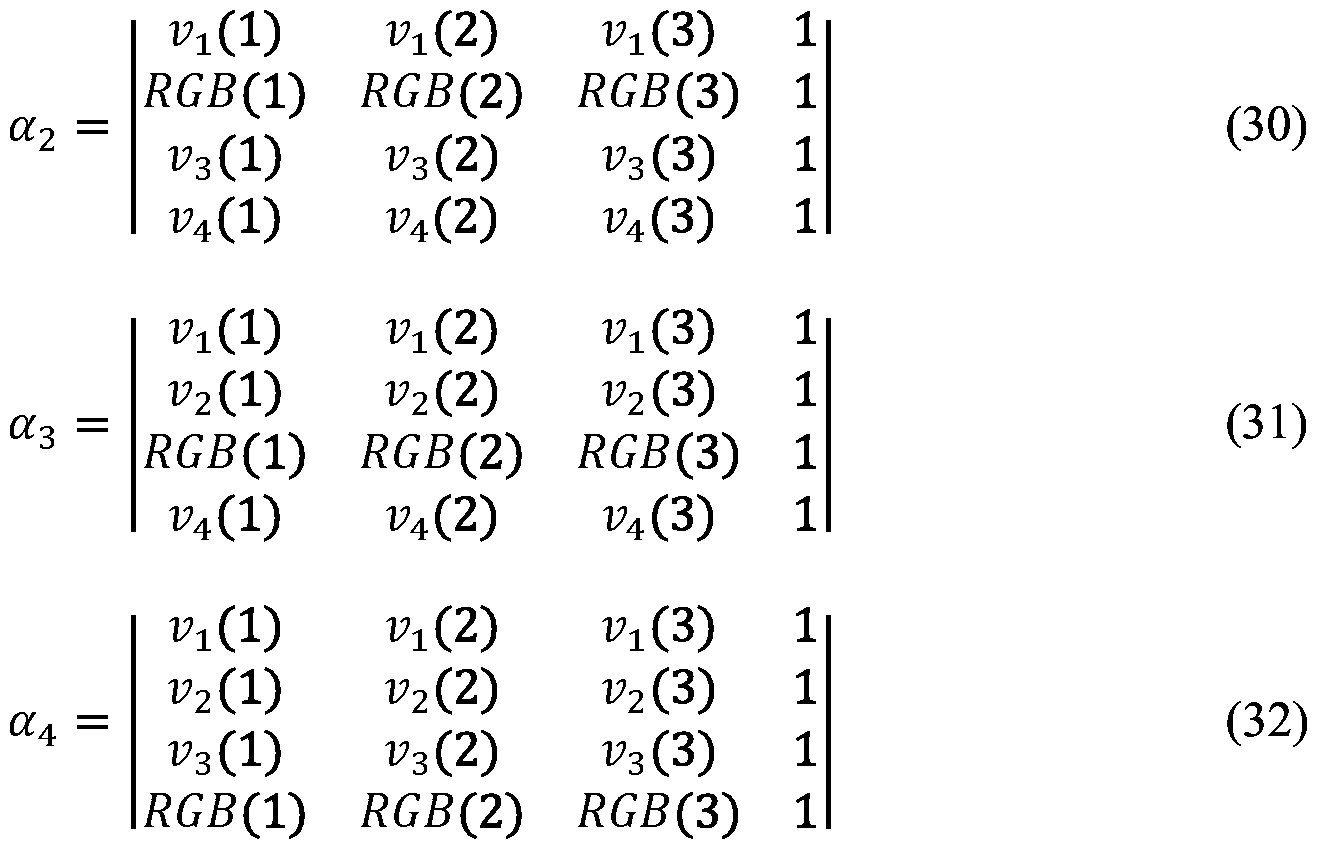
Claims
Priority Applications (10)
| Application Number | Priority Date | Filing Date | Title |
|---|---|---|---|
| RU2019128143A RU2718167C1 (en) | 2017-03-06 | 2018-03-02 | Method and apparatus for rendering color images |
| EP18710988.9A EP3593340B1 (en) | 2017-03-06 | 2018-03-02 | Method for rendering color images |
| KR1020197026472A KR102174880B1 (en) | 2017-03-06 | 2018-03-02 | How to render color images |
| CA3050122A CA3050122C (en) | 2017-03-06 | 2018-03-02 | Method and apparatus for rendering color images |
| AU2018230927A AU2018230927B2 (en) | 2017-03-06 | 2018-03-02 | Method for rendering color images |
| CN202011127863.7A CN112259034B (en) | 2017-03-06 | 2018-03-02 | Method and apparatus for presenting color images |
| CN201880015039.7A CN110392911B (en) | 2017-03-06 | 2018-03-02 | Method and apparatus for presenting color image |
| JP2019548459A JP7083837B2 (en) | 2017-03-06 | 2018-03-02 | Methods and equipment for rendering color images |
| AU2020227089A AU2020227089B2 (en) | 2017-03-06 | 2020-09-03 | Method for Rendering Color Images |
| AU2022200251A AU2022200251B2 (en) | 2017-03-06 | 2022-01-14 | Method and apparatus for rendering color images |
Applications Claiming Priority (14)
| Application Number | Priority Date | Filing Date | Title |
|---|---|---|---|
| US201762467291P | 2017-03-06 | 2017-03-06 | |
| US62/467,291 | 2017-03-06 | ||
| US201762509031P | 2017-05-19 | 2017-05-19 | |
| US62/509,031 | 2017-05-19 | ||
| US201762509087P | 2017-05-20 | 2017-05-20 | |
| US62/509,087 | 2017-05-20 | ||
| US201762585692P | 2017-11-14 | 2017-11-14 | |
| US201762585761P | 2017-11-14 | 2017-11-14 | |
| US201762585614P | 2017-11-14 | 2017-11-14 | |
| US62/585,761 | 2017-11-14 | ||
| US62/585,692 | 2017-11-14 | ||
| US62/585,614 | 2017-11-14 | ||
| US201762591188P | 2017-11-27 | 2017-11-27 | |
| US62/591,188 | 2017-11-27 |
Publications (1)
| Publication Number | Publication Date |
|---|---|
| WO2018164942A1 true WO2018164942A1 (en) | 2018-09-13 |
Family
ID=61627205
Family Applications (1)
| Application Number | Title | Priority Date | Filing Date |
|---|---|---|---|
| PCT/US2018/020588 WO2018164942A1 (en) | 2017-03-06 | 2018-03-02 | Method for rendering color images |
Country Status (10)
| Country | Link |
|---|---|
| US (4) | US10467984B2 (en) |
| EP (1) | EP3593340B1 (en) |
| JP (3) | JP7083837B2 (en) |
| KR (1) | KR102174880B1 (en) |
| CN (2) | CN110392911B (en) |
| AU (3) | AU2018230927B2 (en) |
| CA (3) | CA3050122C (en) |
| RU (3) | RU2718167C1 (en) |
| TW (2) | TWI718685B (en) |
| WO (1) | WO2018164942A1 (en) |
Cited By (2)
| Publication number | Priority date | Publication date | Assignee | Title |
|---|---|---|---|---|
| WO2022269596A1 (en) * | 2021-06-24 | 2022-12-29 | Elbit Systems Electro-Optics Elop Ltd | Color rendering system and method |
| US11972713B2 (en) | 2021-05-06 | 2024-04-30 | Apple Inc. | Systems and methods for point defect compensation |
Families Citing this family (43)
| Publication number | Priority date | Publication date | Assignee | Title |
|---|---|---|---|---|
| CN110610687B (en) * | 2013-03-01 | 2022-07-12 | 伊英克公司 | Method for driving electro-optic display |
| US10600213B2 (en) * | 2016-02-27 | 2020-03-24 | Focal Sharp, Inc. | Method and apparatus for color-preserving spectrum reshape |
| CN110392911B (en) * | 2017-03-06 | 2021-09-24 | 伊英克公司 | Method and apparatus for presenting color image |
| CN117711284A (en) * | 2018-07-23 | 2024-03-15 | 奇跃公司 | In-field subcode timing in a field sequential display |
| CN109285520B (en) * | 2018-11-20 | 2020-09-29 | 惠科股份有限公司 | Pixel driving method and pixel driving device |
| DE102019101777B4 (en) * | 2019-01-24 | 2023-11-02 | Carl Zeiss Meditec Ag | Microscopy method |
| WO2020232537A1 (en) * | 2019-05-17 | 2020-11-26 | Fenoto Technologies Inc. | Electronic paper display system |
| KR102599950B1 (en) | 2019-07-30 | 2023-11-09 | 삼성전자주식회사 | Electronic device and control method thereof |
| KR102757198B1 (en) * | 2019-10-17 | 2025-01-21 | 에스케이하이닉스 주식회사 | Image sensor |
| CN112863457A (en) * | 2019-11-27 | 2021-05-28 | 深圳市万普拉斯科技有限公司 | Display brightness adjusting method and device, electronic equipment and storage medium |
| EP4010894A1 (en) * | 2019-12-11 | 2022-06-15 | Google LLC | Color calibration of display modules using a reduced number of display characteristic measurements |
| US11250810B2 (en) * | 2020-06-03 | 2022-02-15 | Facebook Technologies, Llc. | Rendering images on displays |
| CN115668049A (en) | 2020-06-05 | 2023-01-31 | 伊英克加利福尼亚有限责任公司 | Electrophoretic display device |
| TWI739515B (en) * | 2020-07-14 | 2021-09-11 | 瑞昱半導體股份有限公司 | Debanding determination method for image and debanding determination circuit thereof |
| US11300793B1 (en) * | 2020-08-20 | 2022-04-12 | Facebook Technologies, Llc. | Systems and methods for color dithering |
| CN112084513B (en) * | 2020-08-28 | 2022-03-04 | 山东科技大学 | Visual encryption method for color image |
| US12181767B2 (en) | 2020-09-15 | 2024-12-31 | E Ink Corporation | Five-particle electrophoretic medium with improved black optical state |
| US11846863B2 (en) | 2020-09-15 | 2023-12-19 | E Ink Corporation | Coordinated top electrode—drive electrode voltages for switching optical state of electrophoretic displays using positive and negative voltages of different magnitudes |
| CA3189174A1 (en) | 2020-09-15 | 2022-03-24 | Stephen J. Telfer | Improved driving voltages for advanced color electrophoretic displays and displays with improved driving voltages |
| CA3188075A1 (en) | 2020-09-15 | 2022-03-24 | Stephen J. Telfer | Four particle electrophoretic medium providing fast, high-contrast optical state switching |
| US11450262B2 (en) * | 2020-10-01 | 2022-09-20 | E Ink Corporation | Electro-optic displays, and methods for driving same |
| KR102636771B1 (en) * | 2020-11-02 | 2024-02-14 | 이 잉크 코포레이션 | Method and apparatus for rendering color images |
| AU2021368677B2 (en) | 2020-11-02 | 2023-12-21 | E Ink Corporation | Driving sequences to remove prior state information from color electrophoretic displays |
| KR102761800B1 (en) | 2020-11-02 | 2025-02-03 | 이 잉크 코포레이션 | Enhanced push-pull (EPP) waveforms for achieving primary color sets in multicolor electrophoretic displays |
| WO2022173691A1 (en) | 2021-02-09 | 2022-08-18 | E Ink Corporation | Continuous waveform driving in multi-color electrophoretic displays |
| TWI871517B (en) * | 2021-07-20 | 2025-02-01 | 美商Oled沃克斯有限責任公司 | Display with three regions of color space |
| CN117897657A (en) | 2021-09-06 | 2024-04-16 | 伊英克公司 | Method for driving an electrophoretic display device |
| WO2023043714A1 (en) | 2021-09-14 | 2023-03-23 | E Ink Corporation | Coordinated top electrode - drive electrode voltages for switching optical state of electrophoretic displays using positive and negative voltages of different magnitudes |
| CN115914519A (en) * | 2021-09-30 | 2023-04-04 | 晶门科技(深圳)有限公司 | Frame rate conversion device and method based on directional modulation and dithering |
| TWI830484B (en) * | 2021-11-05 | 2024-01-21 | 美商電子墨水股份有限公司 | A method for driving a color electrophortic display having a plurality of display pixels in an array, and an electrophortic display configured to carry out the method |
| CN114494467B (en) * | 2021-12-15 | 2025-06-10 | 科大讯飞股份有限公司 | Image color migration method, device, electronic equipment and storage medium |
| KR20240125034A (en) | 2021-12-22 | 2024-08-19 | 이 잉크 코포레이션 | High voltage drive using top plane switching with zero voltage frames between drive frames |
| KR20240129051A (en) | 2022-01-04 | 2024-08-27 | 이 잉크 코포레이션 | Electrophoretic media comprising combinations of charge modifiers and electrophoretic particles |
| US11984088B2 (en) * | 2022-04-27 | 2024-05-14 | E Ink Corporation | Color displays configured to convert RGB image data for display on advanced color electronic paper |
| WO2024044119A1 (en) | 2022-08-25 | 2024-02-29 | E Ink Corporation | Transitional driving modes for impulse balancing when switching between global color mode and direct update mode for electrophoretic displays |
| US20240402562A1 (en) | 2023-06-05 | 2024-12-05 | E Ink Corporation | Color electrophoretic medium having four pigment particle system addressable by waveforms having four voltage levels |
| WO2025006130A1 (en) | 2023-06-27 | 2025-01-02 | E Ink Corporation | Electrophoretic device with ambient light sensor and adaptive whiteness restoring and color balancing frontlight |
| US20250006146A1 (en) | 2023-06-27 | 2025-01-02 | E Ink Corporation | Time-shifted waveforms for multi-particle electrophoretic displays providing low-flash image updates |
| US20250006145A1 (en) | 2023-06-27 | 2025-01-02 | E Ink Corporation | Multi-particle electrophoretic display having low-flash image updates |
| CN116994532B (en) | 2023-09-22 | 2023-12-15 | 汉朔科技股份有限公司 | A display content updating method, device, equipment and medium |
| US20250118271A1 (en) | 2023-10-05 | 2025-04-10 | E Ink Corporation | Staged gate voltage control |
| WO2025128843A1 (en) | 2023-12-15 | 2025-06-19 | E Ink Corporation | Fast response color waveforms for multiparticle electrophoretic displays |
| WO2025136446A1 (en) | 2023-12-22 | 2025-06-26 | E Ink Corporation | Five-particle electrophoretic medium with improved black optical state |
Citations (207)
| Publication number | Priority date | Publication date | Assignee | Title |
|---|---|---|---|---|
| US5455600A (en) * | 1992-12-23 | 1995-10-03 | Microsoft Corporation | Method and apparatus for mapping colors in an image through dithering and diffusion |
| EP0677950A1 (en) | 1994-04-15 | 1995-10-18 | Hewlett-Packard Company | System and method for dithering and quantizing image data to optimize visual quality of a color recovered image |
| US5880857A (en) | 1994-12-01 | 1999-03-09 | Xerox Corporation | Error diffusion pattern shifting reduction through programmable threshold perturbation |
| US5930026A (en) | 1996-10-25 | 1999-07-27 | Massachusetts Institute Of Technology | Nonemissive displays and piezoelectric power supplies therefor |
| US6017584A (en) | 1995-07-20 | 2000-01-25 | E Ink Corporation | Multi-color electrophoretic displays and materials for making the same |
| US6445489B1 (en) | 1998-03-18 | 2002-09-03 | E Ink Corporation | Electrophoretic displays and systems for addressing such displays |
| US6504524B1 (en) | 2000-03-08 | 2003-01-07 | E Ink Corporation | Addressing methods for displays having zero time-average field |
| US6512354B2 (en) | 1998-07-08 | 2003-01-28 | E Ink Corporation | Method and apparatus for sensing the state of an electrophoretic display |
| US6531997B1 (en) | 1999-04-30 | 2003-03-11 | E Ink Corporation | Methods for addressing electrophoretic displays |
| US6545797B2 (en) | 2001-06-11 | 2003-04-08 | Sipix Imaging, Inc. | Process for imagewise opening and filling color display components and color displays manufactured thereof |
| US20030102858A1 (en) | 1998-07-08 | 2003-06-05 | E Ink Corporation | Method and apparatus for determining properties of an electrophoretic display |
| US6664944B1 (en) | 1995-07-20 | 2003-12-16 | E-Ink Corporation | Rear electrode structures for electrophoretic displays |
| US6753999B2 (en) | 1998-03-18 | 2004-06-22 | E Ink Corporation | Electrophoretic displays in portable devices and systems for addressing such displays |
| US6788452B2 (en) | 2001-06-11 | 2004-09-07 | Sipix Imaging, Inc. | Process for manufacture of improved color displays |
| US6825970B2 (en) | 2001-09-14 | 2004-11-30 | E Ink Corporation | Methods for addressing electro-optic materials |
| US20040246562A1 (en) | 2003-05-16 | 2004-12-09 | Sipix Imaging, Inc. | Passive matrix electrophoretic display driving scheme |
| JP2005039413A (en) * | 2003-07-17 | 2005-02-10 | Seiko Epson Corp | Image processing apparatus, image processing method, and program |
| US6864875B2 (en) | 1998-04-10 | 2005-03-08 | E Ink Corporation | Full color reflective display with multichromatic sub-pixels |
| US6900851B2 (en) | 2002-02-08 | 2005-05-31 | E Ink Corporation | Electro-optic displays and optical systems for addressing such displays |
| US6914714B2 (en) | 2001-06-11 | 2005-07-05 | Sipix Imaging Inc. | Process for imagewise opening and filling color display components and color displays manufactured thereof |
| US20050253777A1 (en) | 2004-05-12 | 2005-11-17 | E Ink Corporation | Tiled displays and methods for driving same |
| US7012600B2 (en) | 1999-04-30 | 2006-03-14 | E Ink Corporation | Methods for driving bistable electro-optic displays, and apparatus for use therein |
| US7023420B2 (en) | 2000-11-29 | 2006-04-04 | E Ink Corporation | Electronic display with photo-addressing means |
| US7034783B2 (en) | 2003-08-19 | 2006-04-25 | E Ink Corporation | Method for controlling electro-optic display |
| US7038670B2 (en) | 2002-08-16 | 2006-05-02 | Sipix Imaging, Inc. | Electrophoretic display with dual mode switching |
| US7038656B2 (en) | 2002-08-16 | 2006-05-02 | Sipix Imaging, Inc. | Electrophoretic display with dual-mode switching |
| US7046228B2 (en) | 2001-08-17 | 2006-05-16 | Sipix Imaging, Inc. | Electrophoretic display with dual mode switching |
| US7052571B2 (en) | 2000-03-03 | 2006-05-30 | Sipix Imaging, Inc. | Electrophoretic display and process for its manufacture |
| US7061166B2 (en) | 2003-05-27 | 2006-06-13 | Fuji Photo Film Co., Ltd. | Laminated structure and method of manufacturing the same |
| US7061662B2 (en) | 2003-10-07 | 2006-06-13 | Sipix Imaging, Inc. | Electrophoretic display with thermal control |
| US7116466B2 (en) | 2004-07-27 | 2006-10-03 | E Ink Corporation | Electro-optic displays |
| US7119772B2 (en) | 1999-04-30 | 2006-10-10 | E Ink Corporation | Methods for driving bistable electro-optic displays, and apparatus for use therein |
| US20070008335A1 (en) * | 2005-07-08 | 2007-01-11 | Bhattacharjya Anoop K | Low noise dithering and color palette designs |
| US7167155B1 (en) | 1995-07-20 | 2007-01-23 | E Ink Corporation | Color electrophoretic displays |
| US7177066B2 (en) | 2003-10-24 | 2007-02-13 | Sipix Imaging, Inc. | Electrophoretic display driving scheme |
| US7193625B2 (en) | 1999-04-30 | 2007-03-20 | E Ink Corporation | Methods for driving electro-optic displays, and apparatus for use therein |
| US7202847B2 (en) | 2002-06-28 | 2007-04-10 | E Ink Corporation | Voltage modulated driver circuits for electro-optic displays |
| US20070103427A1 (en) | 2003-11-25 | 2007-05-10 | Koninklijke Philips Electronice N.V. | Display apparatus with a display device and a cyclic rail-stabilized method of driving the display device |
| US20070176912A1 (en) | 2005-12-09 | 2007-08-02 | Beames Michael H | Portable memory devices with polymeric displays |
| US7259744B2 (en) | 1995-07-20 | 2007-08-21 | E Ink Corporation | Dielectrophoretic displays |
| US20080024482A1 (en) | 2002-06-13 | 2008-01-31 | E Ink Corporation | Methods for driving electro-optic displays |
| US20080024429A1 (en) | 2006-07-25 | 2008-01-31 | E Ink Corporation | Electrophoretic displays using gaseous fluids |
| US7327511B2 (en) | 2004-03-23 | 2008-02-05 | E Ink Corporation | Light modulators |
| US20080043318A1 (en) | 2005-10-18 | 2008-02-21 | E Ink Corporation | Color electro-optic displays, and processes for the production thereof |
| US7385751B2 (en) | 2001-06-11 | 2008-06-10 | Sipix Imaging, Inc. | Process for imagewise opening and filling color display components and color displays manufactured thereof |
| US20080136774A1 (en) | 2004-07-27 | 2008-06-12 | E Ink Corporation | Methods for driving electrophoretic displays using dielectrophoretic forces |
| US7408699B2 (en) | 2005-09-28 | 2008-08-05 | Sipix Imaging, Inc. | Electrophoretic display and methods of addressing such display |
| US7453445B2 (en) | 2004-08-13 | 2008-11-18 | E Ink Corproation | Methods for driving electro-optic displays |
| US20080291129A1 (en) | 2007-05-21 | 2008-11-27 | E Ink Corporation | Methods for driving video electro-optic displays |
| US20080303780A1 (en) | 2007-06-07 | 2008-12-11 | Sipix Imaging, Inc. | Driving methods and circuit for bi-stable displays |
| US7492339B2 (en) | 2004-03-26 | 2009-02-17 | E Ink Corporation | Methods for driving bistable electro-optic displays |
| US7492505B2 (en) | 2001-08-17 | 2009-02-17 | Sipix Imaging, Inc. | Electrophoretic display with dual mode switching |
| US7528822B2 (en) | 2001-11-20 | 2009-05-05 | E Ink Corporation | Methods for driving electro-optic displays |
| US20090174651A1 (en) | 1995-07-20 | 2009-07-09 | E Ink Corporation | Addressing schemes for electronic displays |
| US20090195568A1 (en) | 2003-03-31 | 2009-08-06 | E Ink Corporation | Methods for driving electro-optic displays |
| US7583251B2 (en) | 1995-07-20 | 2009-09-01 | E Ink Corporation | Dielectrophoretic displays |
| US20090225398A1 (en) | 2002-09-03 | 2009-09-10 | E Ink Corporation | Electro-optic displays |
| US7602374B2 (en) | 2003-09-19 | 2009-10-13 | E Ink Corporation | Methods for reducing edge effects in electro-optic displays |
| US7612760B2 (en) | 2005-02-17 | 2009-11-03 | Seiko Epson Corporation | Electrophoresis device, method of driving electrophoresis device, and electronic apparatus |
| US7667684B2 (en) | 1998-07-08 | 2010-02-23 | E Ink Corporation | Methods for achieving improved color in microencapsulated electrophoretic devices |
| US7679599B2 (en) | 2005-03-04 | 2010-03-16 | Seiko Epson Corporation | Electrophoretic device, method of driving electrophoretic device, and electronic apparatus |
| US7683606B2 (en) | 2006-05-26 | 2010-03-23 | Sipix Imaging, Inc. | Flexible display testing and inspection |
| US7684108B2 (en) | 2004-05-12 | 2010-03-23 | Sipix Imaging, Inc. | Process for the manufacture of electrophoretic displays |
| US7729039B2 (en) | 2002-06-10 | 2010-06-01 | E Ink Corporation | Components and methods for use in electro-optic displays |
| US20100194733A1 (en) | 2009-01-30 | 2010-08-05 | Craig Lin | Multiple voltage level driving for electrophoretic displays |
| US20100194789A1 (en) | 2009-01-30 | 2010-08-05 | Craig Lin | Partial image update for electrophoretic displays |
| US7787169B2 (en) | 2002-03-18 | 2010-08-31 | E Ink Corporation | Electro-optic displays, and methods for driving same |
| US7791789B2 (en) | 1995-07-20 | 2010-09-07 | E Ink Corporation | Multi-color electrophoretic displays and materials for making the same |
| US7800813B2 (en) | 2002-07-17 | 2010-09-21 | Sipix Imaging, Inc. | Methods and compositions for improved electrophoretic display performance |
| US20100283804A1 (en) | 2009-05-11 | 2010-11-11 | Sipix Imaging, Inc. | Driving Methods And Waveforms For Electrophoretic Displays |
| US7839564B2 (en) | 2002-09-03 | 2010-11-23 | E Ink Corporation | Components and methods for use in electro-optic displays |
| US7859742B1 (en) | 2009-12-02 | 2010-12-28 | Sipix Technology, Inc. | Frequency conversion correction circuit for electrophoretic displays |
| US20110043543A1 (en) | 2009-08-18 | 2011-02-24 | Hui Chen | Color tuning for electrophoretic display |
| US20110063314A1 (en) | 2009-09-15 | 2011-03-17 | Wen-Pin Chiu | Display controller system |
| US7910175B2 (en) | 2003-03-25 | 2011-03-22 | E Ink Corporation | Processes for the production of electrophoretic displays |
| US7952557B2 (en) | 2001-11-20 | 2011-05-31 | E Ink Corporation | Methods and apparatus for driving electro-optic displays |
| US7952790B2 (en) | 2006-03-22 | 2011-05-31 | E Ink Corporation | Electro-optic media produced using ink jet printing |
| US7956841B2 (en) | 1995-07-20 | 2011-06-07 | E Ink Corporation | Stylus-based addressing structures for displays |
| US7982479B2 (en) | 2006-04-07 | 2011-07-19 | Sipix Imaging, Inc. | Inspection methods for defects in electrophoretic display and related devices |
| US7982941B2 (en) | 2008-09-02 | 2011-07-19 | Sipix Imaging, Inc. | Color display devices |
| US20110175875A1 (en) | 2010-01-15 | 2011-07-21 | Craig Lin | Driving methods with variable frame time |
| US20110193841A1 (en) | 2002-06-13 | 2011-08-11 | E Ink Corporation | Methods for driving electrophoretic displays using dielectrophoretic forces |
| US20110193840A1 (en) | 1995-07-20 | 2011-08-11 | E Ink Corporation | Methods for driving electrophoretic displays using dielectrophoretic forces |
| US20110221740A1 (en) | 2010-03-12 | 2011-09-15 | Sipix Technology Inc. | Driving method of electrophoretic display |
| US8040594B2 (en) | 1997-08-28 | 2011-10-18 | E Ink Corporation | Multi-color electrophoretic displays |
| US8054526B2 (en) | 2008-03-21 | 2011-11-08 | E Ink Corporation | Electro-optic displays, and color filters for use therein |
| US8077141B2 (en) | 2002-12-16 | 2011-12-13 | E Ink Corporation | Backplanes for electro-optic displays |
| US20120001957A1 (en) | 2010-06-30 | 2012-01-05 | Sipix Technology Inc. | Electrophoretic display and driving method thereof |
| US8098418B2 (en) | 2009-03-03 | 2012-01-17 | E. Ink Corporation | Electro-optic displays, and color filters for use therein |
| US8125501B2 (en) | 2001-11-20 | 2012-02-28 | E Ink Corporation | Voltage modulated driver circuits for electro-optic displays |
| US8159636B2 (en) | 2005-04-08 | 2012-04-17 | Sipix Imaging, Inc. | Reflective displays and processes for their manufacture |
| US20120098740A1 (en) | 2010-10-20 | 2012-04-26 | Sipix Technology Inc. | Electro-phoretic display apparatus |
| US8174490B2 (en) | 2003-06-30 | 2012-05-08 | E Ink Corporation | Methods for driving electrophoretic displays |
| US8213076B2 (en) | 1997-08-28 | 2012-07-03 | E Ink Corporation | Multi-color electrophoretic displays and materials for making the same |
| US8243013B1 (en) | 2007-05-03 | 2012-08-14 | Sipix Imaging, Inc. | Driving bistable displays |
| US8274472B1 (en) | 2007-03-12 | 2012-09-25 | Sipix Imaging, Inc. | Driving methods for bistable displays |
| US8289250B2 (en) | 2004-03-31 | 2012-10-16 | E Ink Corporation | Methods for driving electro-optic displays |
| US8300006B2 (en) | 2003-10-03 | 2012-10-30 | E Ink Corporation | Electrophoretic display unit |
| US8314784B2 (en) | 2008-04-11 | 2012-11-20 | E Ink Corporation | Methods for driving electro-optic displays |
| US8363299B2 (en) | 2002-06-10 | 2013-01-29 | E Ink Corporation | Electro-optic displays, and processes for the production thereof |
| US8373649B2 (en) | 2008-04-11 | 2013-02-12 | Seiko Epson Corporation | Time-overlapping partial-panel updating of a bistable electro-optic display |
| US20130063333A1 (en) | 2002-10-16 | 2013-03-14 | E Ink Corporation | Electrophoretic displays |
| US8422116B2 (en) | 2008-04-03 | 2013-04-16 | Sipix Imaging, Inc. | Color display devices |
| US20130120656A1 (en) * | 2010-07-22 | 2013-05-16 | Dolby Laboratories Licensing Corporation | Display Management Server |
| US8456414B2 (en) | 2008-08-01 | 2013-06-04 | Sipix Imaging, Inc. | Gamma adjustment with error diffusion for electrophoretic displays |
| WO2013081885A1 (en) * | 2011-11-30 | 2013-06-06 | Qualcomm Mems Technologies, Inc. | Methods and apparatus for interpolating colors |
| US8462102B2 (en) | 2008-04-25 | 2013-06-11 | Sipix Imaging, Inc. | Driving methods for bistable displays |
| US20130194250A1 (en) | 2012-02-01 | 2013-08-01 | E Ink Corporation | Methods for driving electro-optic displays |
| US8503063B2 (en) | 2008-12-30 | 2013-08-06 | Sipix Imaging, Inc. | Multicolor display architecture using enhanced dark state |
| US8514168B2 (en) | 2003-10-07 | 2013-08-20 | Sipix Imaging, Inc. | Electrophoretic display with thermal control |
| US8537105B2 (en) | 2010-10-21 | 2013-09-17 | Sipix Technology Inc. | Electro-phoretic display apparatus |
| US20130249782A1 (en) | 2012-03-26 | 2013-09-26 | Sipix Technology Inc. | Electrophoretic display module and operating method thereof and electrophoretic display system using the same |
| US8558786B2 (en) | 2010-01-20 | 2013-10-15 | Sipix Imaging, Inc. | Driving methods for electrophoretic displays |
| US8558783B2 (en) | 2001-11-20 | 2013-10-15 | E Ink Corporation | Electro-optic displays with reduced remnant voltage |
| US8558855B2 (en) | 2008-10-24 | 2013-10-15 | Sipix Imaging, Inc. | Driving methods for electrophoretic displays |
| US8576470B2 (en) | 2010-06-02 | 2013-11-05 | E Ink Corporation | Electro-optic displays, and color alters for use therein |
| US8576259B2 (en) | 2009-04-22 | 2013-11-05 | Sipix Imaging, Inc. | Partial update driving methods for electrophoretic displays |
| US8576164B2 (en) | 2009-10-26 | 2013-11-05 | Sipix Imaging, Inc. | Spatially combined waveforms for electrophoretic displays |
| US8576475B2 (en) | 2009-07-08 | 2013-11-05 | E Ink Holdings Inc. | MEMS switch |
| US8593396B2 (en) | 2001-11-20 | 2013-11-26 | E Ink Corporation | Methods and apparatus for driving electro-optic displays |
| US20130321278A1 (en) | 2012-06-01 | 2013-12-05 | E Ink Corporation | Methods for driving electro-optic displays |
| US8605354B2 (en) | 2011-09-02 | 2013-12-10 | Sipix Imaging, Inc. | Color display devices |
| US8605032B2 (en) | 2010-06-30 | 2013-12-10 | Sipix Technology Inc. | Electrophoretic display with changeable frame updating speed and driving method thereof |
| US20130335782A1 (en) * | 2012-06-14 | 2013-12-19 | Brother Kogyo Kabushiki Kaisha | Print control device executing error diffusion process using random number |
| US8643595B2 (en) | 2004-10-25 | 2014-02-04 | Sipix Imaging, Inc. | Electrophoretic display driving approaches |
| US8649084B2 (en) | 2011-09-02 | 2014-02-11 | Sipix Imaging, Inc. | Color display devices |
| US8665206B2 (en) | 2010-08-10 | 2014-03-04 | Sipix Imaging, Inc. | Driving method to neutralize grey level shift for electrophoretic displays |
| US8670174B2 (en) | 2010-11-30 | 2014-03-11 | Sipix Imaging, Inc. | Electrophoretic display fluid |
| US20140078576A1 (en) | 2010-03-02 | 2014-03-20 | Sipix Imaging, Inc. | Electrophoretic display device |
| US8681191B2 (en) | 2010-07-08 | 2014-03-25 | Sipix Imaging, Inc. | Three dimensional driving scheme for electrophoretic display devices |
| US20140085355A1 (en) | 2012-09-26 | 2014-03-27 | Sipix Technology Inc. | Electro-phoretic display and method for driving the same |
| US20140092465A1 (en) | 2012-10-02 | 2014-04-03 | Sipix Imaging, Inc. | Color display device |
| US8704756B2 (en) | 2010-05-26 | 2014-04-22 | Sipix Imaging, Inc. | Color display architecture and driving methods |
| US8786935B2 (en) | 2011-06-02 | 2014-07-22 | Sipix Imaging, Inc. | Color electrophoretic display |
| US20140204012A1 (en) | 2013-01-24 | 2014-07-24 | Sipix Technology Inc. | Electrophoretic display and method for driving panel thereof |
| US8797634B2 (en) | 2010-11-30 | 2014-08-05 | E Ink Corporation | Multi-color electrophoretic displays |
| US20140218277A1 (en) | 2013-02-07 | 2014-08-07 | Sipix Technology, Inc. | Electrophoretic display and method of operating an electrophoretic display |
| US8810525B2 (en) | 2009-10-05 | 2014-08-19 | E Ink California, Llc | Electronic information displays |
| US20140240373A1 (en) | 2013-02-27 | 2014-08-28 | E Ink Corporation | Methods for driving electro-optic displays |
| US20140240210A1 (en) | 2013-02-25 | 2014-08-28 | Sipix Technology, Inc. | Electrophoretic display and method of driving an electrophoretic display |
| US20140253425A1 (en) | 2013-03-07 | 2014-09-11 | E Ink Corporation | Method and apparatus for driving electro-optic displays |
| US20140267365A1 (en) * | 2013-03-14 | 2014-09-18 | Qualcomm Incorporated | Spectral color reproduction using a high-dimension reflective display |
| US20140270721A1 (en) * | 2008-09-19 | 2014-09-18 | Dolby Laboratories Licensing Corporation | Upstream quality enhancement signal processing for resource constrained client devices |
| US20140293398A1 (en) | 2013-03-29 | 2014-10-02 | Sipix Imaging, Inc. | Electrophoretic display device |
| US20140292830A1 (en) | 2013-03-01 | 2014-10-02 | E Ink Corporation | Methods for driving electro-optic displays |
| US8873129B2 (en) | 2011-04-07 | 2014-10-28 | E Ink Corporation | Tetrachromatic color filter array for reflective display |
| US20140333685A1 (en) | 2013-07-30 | 2014-11-13 | E Ink Corporation | Methods for driving electro-optic displays |
| US20140340736A1 (en) | 2013-05-17 | 2014-11-20 | Sipix Imaging, Inc. | Color display device with color filters |
| US20140340430A1 (en) | 2013-05-14 | 2014-11-20 | E Ink Corporation | Colored electrophoretic displays |
| US20140340734A1 (en) | 2013-05-17 | 2014-11-20 | Sipix Imaging, Inc. | Driving methods for color display devices |
| US8902153B2 (en) | 2007-08-03 | 2014-12-02 | E Ink Corporation | Electro-optic displays, and processes for their production |
| US8902491B2 (en) | 2011-09-23 | 2014-12-02 | E Ink California, Llc | Additive for improving optical performance of an electrophoretic display |
| US20140362213A1 (en) | 2013-06-05 | 2014-12-11 | Vincent Tseng | Residence fall and inactivity monitoring system |
| US8917439B2 (en) | 2012-02-09 | 2014-12-23 | E Ink California, Llc | Shutter mode for color display devices |
| US8928562B2 (en) | 2003-11-25 | 2015-01-06 | E Ink Corporation | Electro-optic displays, and methods for driving same |
| US8928641B2 (en) | 2009-12-02 | 2015-01-06 | Sipix Technology Inc. | Multiplex electrophoretic display driver circuit |
| US8964282B2 (en) | 2012-10-02 | 2015-02-24 | E Ink California, Llc | Color display device |
| US20150070744A1 (en) | 2002-06-10 | 2015-03-12 | E Ink Corporation | Electro-optic display with edge seal |
| WO2015036358A1 (en) * | 2013-09-13 | 2015-03-19 | Thomson Licensing | Method and apparatus for decomposing and reconstructing an high-dynamic-range picture |
| US20150097877A1 (en) | 2013-10-07 | 2015-04-09 | E Ink California, Llc | Driving methods for color display device |
| US20150103394A1 (en) | 2013-10-11 | 2015-04-16 | E Ink California, Llc | Color display device |
| US9013394B2 (en) | 2010-06-04 | 2015-04-21 | E Ink California, Llc | Driving method for electrophoretic displays |
| US9013783B2 (en) | 2011-06-02 | 2015-04-21 | E Ink California, Llc | Color electrophoretic display |
| US9019197B2 (en) | 2011-09-12 | 2015-04-28 | E Ink California, Llc | Driving system for electrophoretic displays |
| US9019198B2 (en) | 2012-07-05 | 2015-04-28 | Sipix Technology Inc. | Driving method of passive display panel and display apparatus |
| US9019318B2 (en) | 2008-10-24 | 2015-04-28 | E Ink California, Llc | Driving methods for electrophoretic displays employing grey level waveforms |
| US20150118390A1 (en) | 2010-07-26 | 2015-04-30 | E Ink Corporation | Electro-optic displays, and components for use therein |
| US9082352B2 (en) | 2010-10-20 | 2015-07-14 | Sipix Technology Inc. | Electro-phoretic display apparatus and driving method thereof |
| US20150198858A1 (en) | 2014-01-14 | 2015-07-16 | E Ink California, Llc | Color display device |
| US20150213749A1 (en) | 2011-09-12 | 2015-07-30 | E Ink California, Llc | Driving system for electrophoretic displays |
| US20150234250A1 (en) | 2014-02-19 | 2015-08-20 | E Ink California, Llc | Color display device |
| US9116412B2 (en) | 2010-05-26 | 2015-08-25 | E Ink California, Llc | Color display architecture and driving methods |
| US20150243243A1 (en) * | 2014-02-25 | 2015-08-27 | Apple Inc. | Server-side adaptive video processing |
| US20150262255A1 (en) | 2014-03-12 | 2015-09-17 | Netseer, Inc. | Search monetization of images embedded in text |
| US20150268531A1 (en) | 2014-03-18 | 2015-09-24 | Sipix Imaging, Inc. | Color display device |
| US9146439B2 (en) | 2011-01-31 | 2015-09-29 | E Ink California, Llc | Color electrophoretic display |
| US20150287354A1 (en) * | 2014-04-03 | 2015-10-08 | Qualcomm Mems Technologies, Inc. | Error-diffusion based temporal dithering for color display devices |
| US20150301246A1 (en) | 2009-08-18 | 2015-10-22 | E Ink California, Llc | Color tuning for electrophoretic display device |
| US9170468B2 (en) | 2013-05-17 | 2015-10-27 | E Ink California, Llc | Color display device |
| US9195111B2 (en) | 2013-02-11 | 2015-11-24 | E Ink Corporation | Patterned electro-optic displays and processes for the production thereof |
| US9199441B2 (en) | 2007-06-28 | 2015-12-01 | E Ink Corporation | Processes for the production of electro-optic displays, and color filters for use therein |
| US9218773B2 (en) | 2013-01-17 | 2015-12-22 | Sipix Technology Inc. | Method and driving apparatus for outputting driving signal to drive electro-phoretic display |
| US9224344B2 (en) | 2013-06-20 | 2015-12-29 | Sipix Technology, Inc. | Electrophoretic display with a compensation circuit for reducing a luminance difference and method thereof |
| US9224338B2 (en) | 2010-03-08 | 2015-12-29 | E Ink California, Llc | Driving methods for electrophoretic displays |
| US9224342B2 (en) | 2007-10-12 | 2015-12-29 | E Ink California, Llc | Approach to adjust driving waveforms for a display device |
| US9230492B2 (en) | 2003-03-31 | 2016-01-05 | E Ink Corporation | Methods for driving electro-optic displays |
| US20160011484A1 (en) | 2014-07-09 | 2016-01-14 | E Ink California, Llc | Color display device |
| US20160026062A1 (en) | 2011-01-31 | 2016-01-28 | E Ink California, Llc | Color electrophoretic display |
| US9251736B2 (en) | 2009-01-30 | 2016-02-02 | E Ink California, Llc | Multiple voltage level driving for electrophoretic displays |
| US9262973B2 (en) | 2013-03-13 | 2016-02-16 | Sipix Technology, Inc. | Electrophoretic display capable of reducing passive matrix coupling effect and method thereof |
| US20160071465A1 (en) | 2013-01-17 | 2016-03-10 | Sipix Technology Inc. | Method and driving apparatus for outputting driving signal to drive electro-phoretic display |
| US9285649B2 (en) | 2013-04-18 | 2016-03-15 | E Ink California, Llc | Color display device |
| US20160085132A1 (en) | 2014-09-10 | 2016-03-24 | E Ink Corporation | Colored electrophoretic displays |
| US9299294B2 (en) | 2010-11-11 | 2016-03-29 | E Ink California, Llc | Driving method for electrophoretic displays with different color states |
| US20160091770A1 (en) | 2014-09-26 | 2016-03-31 | E Ink Corporation | Color sets for low resolution dithering in reflective color displays |
| US20160116818A1 (en) | 2013-04-18 | 2016-04-28 | E Ink California, Inc. | Color display device |
| US9341916B2 (en) | 2010-05-21 | 2016-05-17 | E Ink Corporation | Multi-color electro-optic displays |
| US20160140909A1 (en) | 2014-11-17 | 2016-05-19 | E Ink California, Llc | Color display device |
| US9361836B1 (en) | 2013-12-20 | 2016-06-07 | E Ink Corporation | Aggregate particles for use in electrophoretic color displays |
| US9360733B2 (en) | 2012-10-02 | 2016-06-07 | E Ink California, Llc | Color display device |
| US20160180777A1 (en) | 2010-11-11 | 2016-06-23 | E Ink California, Inc. | Driving method for electrophoretic displays |
| US9383623B2 (en) | 2013-05-17 | 2016-07-05 | E Ink California, Llc | Color display device |
| US9390661B2 (en) | 2009-09-15 | 2016-07-12 | E Ink California, Llc | Display controller system |
| US9390066B2 (en) | 2009-11-12 | 2016-07-12 | Digital Harmonic Llc | Precision measurement of waveforms using deconvolution and windowing |
| US9412314B2 (en) | 2001-11-20 | 2016-08-09 | E Ink Corporation | Methods for driving electro-optic displays |
| US9423666B2 (en) | 2011-09-23 | 2016-08-23 | E Ink California, Llc | Additive for improving optical performance of an electrophoretic display |
| US20170346989A1 (en) | 2016-05-24 | 2017-11-30 | E Ink Corporation | Method for rendering color images |
Family Cites Families (94)
| Publication number | Priority date | Publication date | Assignee | Title |
|---|---|---|---|---|
| AT305765B (en) | 1964-07-23 | 1973-03-12 | Xerox Corp | Photoelectrophoretic imaging device |
| US4418346A (en) | 1981-05-20 | 1983-11-29 | Batchelder J Samuel | Method and apparatus for providing a dielectrophoretic display of visual information |
| JPH0535244A (en) * | 1991-07-30 | 1993-02-12 | Canon Inc | Image processor |
| DE69409048T2 (en) * | 1993-08-18 | 1998-09-03 | Philips Electronics Nv | Arrangement and method for producing a color image |
| US5745094A (en) | 1994-12-28 | 1998-04-28 | International Business Machines Corporation | Electrophoretic display |
| US6137467A (en) | 1995-01-03 | 2000-10-24 | Xerox Corporation | Optically sensitive electric paper |
| US6866760B2 (en) | 1998-08-27 | 2005-03-15 | E Ink Corporation | Electrophoretic medium and process for the production thereof |
| US7411719B2 (en) | 1995-07-20 | 2008-08-12 | E Ink Corporation | Electrophoretic medium and process for the production thereof |
| US5760761A (en) | 1995-12-15 | 1998-06-02 | Xerox Corporation | Highlight color twisting ball display |
| US6055091A (en) | 1996-06-27 | 2000-04-25 | Xerox Corporation | Twisting-cylinder display |
| US5808783A (en) | 1996-06-27 | 1998-09-15 | Xerox Corporation | High reflectance gyricon display |
| US5777782A (en) | 1996-12-24 | 1998-07-07 | Xerox Corporation | Auxiliary optics for a twisting ball display |
| US6301038B1 (en) | 1997-02-06 | 2001-10-09 | University College Dublin | Electrochromic system |
| US7002728B2 (en) | 1997-08-28 | 2006-02-21 | E Ink Corporation | Electrophoretic particles, and processes for the production thereof |
| US6054071A (en) | 1998-01-28 | 2000-04-25 | Xerox Corporation | Poled electrets for gyricon-based electric-paper displays |
| US6704133B2 (en) | 1998-03-18 | 2004-03-09 | E-Ink Corporation | Electro-optic display overlays and systems for addressing such displays |
| CA2329173A1 (en) | 1998-04-27 | 1999-11-04 | E Ink Corporation | Shutter mode microencapsulated electrophoretic display |
| US6241921B1 (en) | 1998-05-15 | 2001-06-05 | Massachusetts Institute Of Technology | Heterogeneous display elements and methods for their fabrication |
| US6304333B1 (en) | 1998-08-19 | 2001-10-16 | Hewlett-Packard Company | Apparatus and method of performing dithering in a simplex in color space |
| US6144361A (en) | 1998-09-16 | 2000-11-07 | International Business Machines Corporation | Transmissive electrophoretic display with vertical electrodes |
| US6184856B1 (en) | 1998-09-16 | 2001-02-06 | International Business Machines Corporation | Transmissive electrophoretic display with laterally adjacent color cells |
| US6225971B1 (en) | 1998-09-16 | 2001-05-01 | International Business Machines Corporation | Reflective electrophoretic display with laterally adjacent color cells using an absorbing panel |
| US6271823B1 (en) | 1998-09-16 | 2001-08-07 | International Business Machines Corporation | Reflective electrophoretic display with laterally adjacent color cells using a reflective panel |
| US6128124A (en) | 1998-10-16 | 2000-10-03 | Xerox Corporation | Additive color electric paper without registration or alignment of individual elements |
| US6147791A (en) | 1998-11-25 | 2000-11-14 | Xerox Corporation | Gyricon displays utilizing rotating elements and magnetic latching |
| US6097531A (en) | 1998-11-25 | 2000-08-01 | Xerox Corporation | Method of making uniformly magnetized elements for a gyricon display |
| CA2385721C (en) | 1999-10-11 | 2009-04-07 | University College Dublin | Electrochromic device |
| US6672921B1 (en) | 2000-03-03 | 2004-01-06 | Sipix Imaging, Inc. | Manufacturing process for electrophoretic display |
| US7715088B2 (en) | 2000-03-03 | 2010-05-11 | Sipix Imaging, Inc. | Electrophoretic display |
| US6788449B2 (en) | 2000-03-03 | 2004-09-07 | Sipix Imaging, Inc. | Electrophoretic display and novel process for its manufacture |
| JP2002091400A (en) * | 2000-09-19 | 2002-03-27 | Matsushita Electric Ind Co Ltd | Liquid crystal display |
| JP4198999B2 (en) | 2001-03-13 | 2008-12-17 | イー インク コーポレイション | Equipment for displaying drawings |
| US7679814B2 (en) | 2001-04-02 | 2010-03-16 | E Ink Corporation | Materials for use in electrophoretic displays |
| ATE324615T1 (en) | 2001-04-02 | 2006-05-15 | E Ink Corp | ELECTROPHOREASE MEDIUM WITH IMPROVED IMAGE STABILITY |
| US6937365B2 (en) | 2001-05-30 | 2005-08-30 | Polaroid Corporation | Rendering images utilizing adaptive error diffusion |
| US20020188053A1 (en) | 2001-06-04 | 2002-12-12 | Sipix Imaging, Inc. | Composition and process for the sealing of microcups in roll-to-roll display manufacturing |
| US7535624B2 (en) | 2001-07-09 | 2009-05-19 | E Ink Corporation | Electro-optic display and materials for use therein |
| RU2237283C2 (en) * | 2001-11-27 | 2004-09-27 | Самсунг Электроникс Ко., Лтд. | Device and method for presenting three-dimensional object on basis of images having depth |
| EP1482354B1 (en) | 2002-03-06 | 2008-04-30 | Bridgestone Corporation | Image displaying apparatus and method |
| EP1497867A2 (en) | 2002-04-24 | 2005-01-19 | E Ink Corporation | Electronic displays |
| EP1527371B1 (en) * | 2002-08-06 | 2012-10-03 | E Ink Corporation | Protection of electro-optic displays against thermal effects |
| TWI229230B (en) | 2002-10-31 | 2005-03-11 | Sipix Imaging Inc | An improved electrophoretic display and novel process for its manufacture |
| US6922276B2 (en) | 2002-12-23 | 2005-07-26 | E Ink Corporation | Flexible electro-optic displays |
| EP1599808A4 (en) * | 2003-03-03 | 2006-11-02 | Rick G Craig | Remotely programmable electro-optic sign |
| US7339715B2 (en) | 2003-03-25 | 2008-03-04 | E Ink Corporation | Processes for the production of electrophoretic displays |
| US7236291B2 (en) | 2003-04-02 | 2007-06-26 | Bridgestone Corporation | Particle use for image display media, image display panel using the particles, and image display device |
| US8319759B2 (en) | 2003-10-08 | 2012-11-27 | E Ink Corporation | Electrowetting displays |
| DE602004016017D1 (en) | 2003-10-08 | 2008-10-02 | E Ink Corp | ELECTRO-wetting DISPLAYS |
| US7984108B2 (en) | 2003-10-08 | 2011-07-19 | Unisys Corporation | Computer system para-virtualization using a hypervisor that is implemented in a partition of the host system |
| US20110164301A1 (en) * | 2003-11-05 | 2011-07-07 | E Ink Corporation | Electro-optic displays, and materials for use therein |
| US8269774B2 (en) * | 2004-03-31 | 2012-09-18 | Trading Technologies International, Inc. | Graphical display with integrated recent period zoom and historical period context data |
| KR100565810B1 (en) * | 2004-06-16 | 2006-03-29 | 삼성전자주식회사 | Color signal processing device and method |
| US7263382B2 (en) * | 2004-06-25 | 2007-08-28 | Qualcomm Incorporated | System and method for background download of digital content to an intermittently connected peripheral device via a wireless device |
| US7773849B2 (en) * | 2004-12-14 | 2010-08-10 | Oms Displays Ltd. | Device and method for optical resizing and backlighting |
| US7408558B2 (en) * | 2005-08-25 | 2008-08-05 | Eastman Kodak Company | Laser-based display having expanded image color |
| US20070081739A1 (en) | 2005-10-11 | 2007-04-12 | International Business Machines Corporation | Modifying text or images when defect pixels are found on a display |
| GB0606680D0 (en) * | 2006-04-03 | 2006-05-10 | Univ Cardiff | Method of and apparatus for detecting degradation of visual performance |
| WO2008020393A1 (en) * | 2006-08-16 | 2008-02-21 | Koninklijke Philips Electronics N.V. | Image gamut mapping |
| JP4930845B2 (en) * | 2007-07-09 | 2012-05-16 | Necアクセステクニカ株式会社 | Image processing apparatus, image processing method, and image processing program |
| US20100149393A1 (en) * | 2008-05-22 | 2010-06-17 | Panavision Imaging, Llc | Increasing the resolution of color sub-pixel arrays |
| FR2937487B1 (en) * | 2008-10-22 | 2010-11-26 | Airbus France | DEVICE AND METHOD FOR COMMUNICATION BETWEEN A PORTABLE COMPUTER SYSTEM AND AVIONIC EQUIPMENT |
| EP2406960A1 (en) * | 2009-03-09 | 2012-01-18 | Koninklijke Philips Electronics N.V. | Multi primary conversion |
| US8525900B2 (en) * | 2009-04-23 | 2013-09-03 | Csr Technology Inc. | Multiple exposure high dynamic range image capture |
| TWI500010B (en) | 2009-09-03 | 2015-09-11 | Prime View Int Co Ltd | Color electrophoretic display and display method thereof |
| JP5859447B2 (en) * | 2009-10-28 | 2016-02-10 | イー インク コーポレイション | Electro-optic display with touch sensor |
| CN102081906A (en) | 2009-11-26 | 2011-06-01 | 元太科技工业股份有限公司 | Color electrophoretic display and display method thereof |
| KR101588336B1 (en) * | 2009-12-17 | 2016-01-26 | 삼성디스플레이 주식회사 | Method for processing data and display apparatus for performing the method |
| JP2011145390A (en) * | 2010-01-13 | 2011-07-28 | Seiko Epson Corp | Electrophoretic display device and electronic equipment |
| US8606009B2 (en) * | 2010-02-04 | 2013-12-10 | Microsoft Corporation | High dynamic range image generation and rendering |
| US8355169B2 (en) * | 2010-08-23 | 2013-01-15 | Ecole Polytechnique Federale De Lausanne (Epfl) | Synthesis of authenticable luminescent color halftone images |
| HUE043376T2 (en) * | 2010-09-16 | 2019-08-28 | Koninklijke Philips Nv | Apparatus and procedures for improved coding of images |
| TW201237529A (en) * | 2011-03-15 | 2012-09-16 | E Ink Corp | Multi-color electrophoretic displays |
| CN103002225B (en) | 2011-04-20 | 2017-04-12 | 高通科技公司 | Multiple exposure high dynamic range image capture |
| US8711167B2 (en) * | 2011-05-10 | 2014-04-29 | Nvidia Corporation | Method and apparatus for generating images using a color field sequential display |
| CN103620667B (en) * | 2011-05-10 | 2016-01-20 | 辉达公司 | For using the method and apparatus of colour field sequential display synthetic image |
| CN103688212B (en) | 2011-05-21 | 2017-11-28 | 伊英克公司 | Electro-optic displays |
| CN102222734B (en) * | 2011-07-07 | 2012-11-14 | 厦门市三安光电科技有限公司 | Method for manufacturing inverted solar cell |
| WO2013056387A1 (en) * | 2011-10-17 | 2013-04-25 | Liu Travis | Universal gamut mapping and color management method |
| US11030936B2 (en) | 2012-02-01 | 2021-06-08 | E Ink Corporation | Methods and apparatus for operating an electro-optic display in white mode |
| US9279906B2 (en) | 2012-08-31 | 2016-03-08 | E Ink California, Llc | Microstructure film |
| US10037735B2 (en) * | 2012-11-16 | 2018-07-31 | E Ink Corporation | Active matrix display with dual driving modes |
| US9275607B2 (en) | 2012-11-21 | 2016-03-01 | Apple Inc. | Dynamic color adjustment for displays using local temperature measurements |
| KR20140081678A (en) * | 2012-12-21 | 2014-07-01 | 소니 주식회사 | Projection-type image display device, image projection method, and computer program |
| US20150070402A1 (en) | 2013-09-12 | 2015-03-12 | Qualcomm Incorporated | Real-time color calibration of displays |
| EP3092800B1 (en) * | 2014-01-07 | 2022-12-28 | Dolby Laboratories Licensing Corporation | Techniques for encoding, decoding and representing high dynamic range images |
| US9613407B2 (en) * | 2014-07-03 | 2017-04-04 | Dolby Laboratories Licensing Corporation | Display management for high dynamic range video |
| KR20160047653A (en) * | 2014-10-22 | 2016-05-03 | 삼성디스플레이 주식회사 | Display apparatus |
| US20160275879A1 (en) * | 2015-03-20 | 2016-09-22 | Microsoft Technology Licensing, Llc | Augmenting content for electronic paper display devices |
| US20160309420A1 (en) * | 2015-04-15 | 2016-10-20 | Qualcomm Incorporated | Adaptation of transmission power and packet size in a wireless docking environment |
| KR102059256B1 (en) * | 2015-06-05 | 2019-12-24 | 애플 인크. | Render and display HDR content |
| US9659388B1 (en) * | 2015-11-12 | 2017-05-23 | Qualcomm Incorporated | White point calibration and gamut mapping for a display |
| CN119644594A (en) * | 2016-07-25 | 2025-03-18 | 奇跃公司 | Image modification, display and visualization using augmented and virtual reality glasses |
| US10509294B2 (en) * | 2017-01-25 | 2019-12-17 | E Ink Corporation | Dual sided electrophoretic display |
| CN110392911B (en) * | 2017-03-06 | 2021-09-24 | 伊英克公司 | Method and apparatus for presenting color image |
-
2018
- 2018-03-02 CN CN201880015039.7A patent/CN110392911B/en active Active
- 2018-03-02 CA CA3050122A patent/CA3050122C/en active Active
- 2018-03-02 US US15/910,081 patent/US10467984B2/en active Active
- 2018-03-02 JP JP2019548459A patent/JP7083837B2/en active Active
- 2018-03-02 EP EP18710988.9A patent/EP3593340B1/en active Active
- 2018-03-02 CN CN202011127863.7A patent/CN112259034B/en active Active
- 2018-03-02 WO PCT/US2018/020588 patent/WO2018164942A1/en active Application Filing
- 2018-03-02 RU RU2019128143A patent/RU2718167C1/en active
- 2018-03-02 CA CA3066397A patent/CA3066397C/en active Active
- 2018-03-02 CA CA3200340A patent/CA3200340A1/en active Pending
- 2018-03-02 AU AU2018230927A patent/AU2018230927B2/en active Active
- 2018-03-02 RU RU2020111069A patent/RU2755676C2/en active
- 2018-03-02 KR KR1020197026472A patent/KR102174880B1/en active Active
- 2018-03-05 TW TW108135052A patent/TWI718685B/en active
- 2018-03-05 TW TW107107282A patent/TWI678586B/en active
-
2019
- 2019-09-19 US US16/576,350 patent/US11094288B2/en active Active
-
2020
- 2020-06-18 JP JP2020105255A patent/JP7299859B2/en active Active
- 2020-09-03 AU AU2020227089A patent/AU2020227089B2/en active Active
-
2021
- 2021-02-10 RU RU2021103228A patent/RU2763851C1/en active
- 2021-07-29 US US17/388,525 patent/US11527216B2/en active Active
-
2022
- 2022-01-14 AU AU2022200251A patent/AU2022200251B2/en active Active
- 2022-11-03 US US17/980,019 patent/US12100369B2/en active Active
-
2023
- 2023-04-14 JP JP2023066315A patent/JP2023083401A/en not_active Withdrawn
Patent Citations (264)
| Publication number | Priority date | Publication date | Assignee | Title |
|---|---|---|---|---|
| US5455600A (en) * | 1992-12-23 | 1995-10-03 | Microsoft Corporation | Method and apparatus for mapping colors in an image through dithering and diffusion |
| EP0677950A1 (en) | 1994-04-15 | 1995-10-18 | Hewlett-Packard Company | System and method for dithering and quantizing image data to optimize visual quality of a color recovered image |
| US5880857A (en) | 1994-12-01 | 1999-03-09 | Xerox Corporation | Error diffusion pattern shifting reduction through programmable threshold perturbation |
| US7956841B2 (en) | 1995-07-20 | 2011-06-07 | E Ink Corporation | Stylus-based addressing structures for displays |
| US7999787B2 (en) | 1995-07-20 | 2011-08-16 | E Ink Corporation | Methods for driving electrophoretic displays using dielectrophoretic forces |
| US7583251B2 (en) | 1995-07-20 | 2009-09-01 | E Ink Corporation | Dielectrophoretic displays |
| US7791789B2 (en) | 1995-07-20 | 2010-09-07 | E Ink Corporation | Multi-color electrophoretic displays and materials for making the same |
| US20090174651A1 (en) | 1995-07-20 | 2009-07-09 | E Ink Corporation | Addressing schemes for electronic displays |
| US7167155B1 (en) | 1995-07-20 | 2007-01-23 | E Ink Corporation | Color electrophoretic displays |
| US20110193840A1 (en) | 1995-07-20 | 2011-08-11 | E Ink Corporation | Methods for driving electrophoretic displays using dielectrophoretic forces |
| US6017584A (en) | 1995-07-20 | 2000-01-25 | E Ink Corporation | Multi-color electrophoretic displays and materials for making the same |
| US6664944B1 (en) | 1995-07-20 | 2003-12-16 | E-Ink Corporation | Rear electrode structures for electrophoretic displays |
| US7259744B2 (en) | 1995-07-20 | 2007-08-21 | E Ink Corporation | Dielectrophoretic displays |
| US8139050B2 (en) | 1995-07-20 | 2012-03-20 | E Ink Corporation | Addressing schemes for electronic displays |
| US8305341B2 (en) | 1995-07-20 | 2012-11-06 | E Ink Corporation | Dielectrophoretic displays |
| US8384658B2 (en) | 1995-07-20 | 2013-02-26 | E Ink Corporation | Electrostatically addressable electrophoretic display |
| US5930026A (en) | 1996-10-25 | 1999-07-27 | Massachusetts Institute Of Technology | Nonemissive displays and piezoelectric power supplies therefor |
| US9268191B2 (en) | 1997-08-28 | 2016-02-23 | E Ink Corporation | Multi-color electrophoretic displays |
| US8593721B2 (en) | 1997-08-28 | 2013-11-26 | E Ink Corporation | Multi-color electrophoretic displays and materials for making the same |
| US8441714B2 (en) | 1997-08-28 | 2013-05-14 | E Ink Corporation | Multi-color electrophoretic displays |
| US8213076B2 (en) | 1997-08-28 | 2012-07-03 | E Ink Corporation | Multi-color electrophoretic displays and materials for making the same |
| US8040594B2 (en) | 1997-08-28 | 2011-10-18 | E Ink Corporation | Multi-color electrophoretic displays |
| US6753999B2 (en) | 1998-03-18 | 2004-06-22 | E Ink Corporation | Electrophoretic displays in portable devices and systems for addressing such displays |
| US6445489B1 (en) | 1998-03-18 | 2002-09-03 | E Ink Corporation | Electrophoretic displays and systems for addressing such displays |
| US20080048970A1 (en) | 1998-04-10 | 2008-02-28 | E Ink Corporation | Full color reflective display with multichromatic sub-pixels |
| US20130278995A1 (en) | 1998-04-10 | 2013-10-24 | E Ink Corporation | Full color reflective display with multichromatic sub-pixels |
| US8466852B2 (en) | 1998-04-10 | 2013-06-18 | E Ink Corporation | Full color reflective display with multichromatic sub-pixels |
| US7075502B1 (en) | 1998-04-10 | 2006-07-11 | E Ink Corporation | Full color reflective display with multichromatic sub-pixels |
| US6864875B2 (en) | 1998-04-10 | 2005-03-08 | E Ink Corporation | Full color reflective display with multichromatic sub-pixels |
| US20120326957A1 (en) | 1998-04-10 | 2012-12-27 | E Ink Corporation | Full color reflective display with multichromatic sub pixels |
| US9293511B2 (en) | 1998-07-08 | 2016-03-22 | E Ink Corporation | Methods for achieving improved color in microencapsulated electrophoretic devices |
| US6512354B2 (en) | 1998-07-08 | 2003-01-28 | E Ink Corporation | Method and apparatus for sensing the state of an electrophoretic display |
| US20030102858A1 (en) | 1998-07-08 | 2003-06-05 | E Ink Corporation | Method and apparatus for determining properties of an electrophoretic display |
| US6995550B2 (en) | 1998-07-08 | 2006-02-07 | E Ink Corporation | Method and apparatus for determining properties of an electrophoretic display |
| US20100156780A1 (en) | 1998-07-08 | 2010-06-24 | E Ink Corporation | Methods for achieving improved color in microencapsulated electrophoretic devices |
| US7667684B2 (en) | 1998-07-08 | 2010-02-23 | E Ink Corporation | Methods for achieving improved color in microencapsulated electrophoretic devices |
| US7312794B2 (en) | 1999-04-30 | 2007-12-25 | E Ink Corporation | Methods for driving electro-optic displays, and apparatus for use therein |
| US7012600B2 (en) | 1999-04-30 | 2006-03-14 | E Ink Corporation | Methods for driving bistable electro-optic displays, and apparatus for use therein |
| US7193625B2 (en) | 1999-04-30 | 2007-03-20 | E Ink Corporation | Methods for driving electro-optic displays, and apparatus for use therein |
| US7119772B2 (en) | 1999-04-30 | 2006-10-10 | E Ink Corporation | Methods for driving bistable electro-optic displays, and apparatus for use therein |
| US20070091418A1 (en) | 1999-04-30 | 2007-04-26 | E Ink Corporation | Methods for driving electro-optic displays, and apparatus for use therein |
| US7688297B2 (en) | 1999-04-30 | 2010-03-30 | E Ink Corporation | Methods for driving bistable electro-optic displays, and apparatus for use therein |
| US20150262551A1 (en) | 1999-04-30 | 2015-09-17 | E Ink Corporation | Methods for driving bistable electro-optic displays, and apparatus for use therein |
| US8558785B2 (en) | 1999-04-30 | 2013-10-15 | E Ink Corporation | Methods for driving bistable electro-optic displays, and apparatus for use therein |
| US6531997B1 (en) | 1999-04-30 | 2003-03-11 | E Ink Corporation | Methods for addressing electrophoretic displays |
| US7733335B2 (en) | 1999-04-30 | 2010-06-08 | E Ink Corporation | Methods for driving bistable electro-optic displays, and apparatus for use therein |
| US7733311B2 (en) | 1999-04-30 | 2010-06-08 | E Ink Corporation | Methods for driving bistable electro-optic displays, and apparatus for use therein |
| US20100220121A1 (en) | 1999-04-30 | 2010-09-02 | E Ink Corporation | Methods for driving bistable electro-optic displays, and apparatus for use therein |
| US7052571B2 (en) | 2000-03-03 | 2006-05-30 | Sipix Imaging, Inc. | Electrophoretic display and process for its manufacture |
| US6504524B1 (en) | 2000-03-08 | 2003-01-07 | E Ink Corporation | Addressing methods for displays having zero time-average field |
| US7023420B2 (en) | 2000-11-29 | 2006-04-04 | E Ink Corporation | Electronic display with photo-addressing means |
| US6545797B2 (en) | 2001-06-11 | 2003-04-08 | Sipix Imaging, Inc. | Process for imagewise opening and filling color display components and color displays manufactured thereof |
| US7385751B2 (en) | 2001-06-11 | 2008-06-10 | Sipix Imaging, Inc. | Process for imagewise opening and filling color display components and color displays manufactured thereof |
| US6914714B2 (en) | 2001-06-11 | 2005-07-05 | Sipix Imaging Inc. | Process for imagewise opening and filling color display components and color displays manufactured thereof |
| US6972893B2 (en) | 2001-06-11 | 2005-12-06 | Sipix Imaging, Inc. | Process for imagewise opening and filling color display components and color displays manufactured thereof |
| US6788452B2 (en) | 2001-06-11 | 2004-09-07 | Sipix Imaging, Inc. | Process for manufacture of improved color displays |
| US7679813B2 (en) | 2001-08-17 | 2010-03-16 | Sipix Imaging, Inc. | Electrophoretic display with dual-mode switching |
| US7046228B2 (en) | 2001-08-17 | 2006-05-16 | Sipix Imaging, Inc. | Electrophoretic display with dual mode switching |
| US7821702B2 (en) | 2001-08-17 | 2010-10-26 | Sipix Imaging, Inc. | Electrophoretic display with dual mode switching |
| US7492505B2 (en) | 2001-08-17 | 2009-02-17 | Sipix Imaging, Inc. | Electrophoretic display with dual mode switching |
| US6825970B2 (en) | 2001-09-14 | 2004-11-30 | E Ink Corporation | Methods for addressing electro-optic materials |
| US7952557B2 (en) | 2001-11-20 | 2011-05-31 | E Ink Corporation | Methods and apparatus for driving electro-optic displays |
| US7528822B2 (en) | 2001-11-20 | 2009-05-05 | E Ink Corporation | Methods for driving electro-optic displays |
| US20160140910A1 (en) | 2001-11-20 | 2016-05-19 | E Ink Corporation | Methods and apparatus for driving electro-optic displays |
| US8558783B2 (en) | 2001-11-20 | 2013-10-15 | E Ink Corporation | Electro-optic displays with reduced remnant voltage |
| US9412314B2 (en) | 2001-11-20 | 2016-08-09 | E Ink Corporation | Methods for driving electro-optic displays |
| US8593396B2 (en) | 2001-11-20 | 2013-11-26 | E Ink Corporation | Methods and apparatus for driving electro-optic displays |
| US9269311B2 (en) | 2001-11-20 | 2016-02-23 | E Ink Corporation | Methods and apparatus for driving electro-optic displays |
| US20150221257A1 (en) | 2001-11-20 | 2015-08-06 | E Ink Corporation | Electro-optic displays with reduced remnant voltage |
| US8125501B2 (en) | 2001-11-20 | 2012-02-28 | E Ink Corporation | Voltage modulated driver circuits for electro-optic displays |
| US20140009817A1 (en) | 2001-11-20 | 2014-01-09 | E Ink Corporation | Electro-optic displays with reduced remnant voltage |
| US6900851B2 (en) | 2002-02-08 | 2005-05-31 | E Ink Corporation | Electro-optic displays and optical systems for addressing such displays |
| US20100265561A1 (en) | 2002-03-18 | 2010-10-21 | E Ink Corporation | Electro-optic displays, and methods for driving same |
| US7787169B2 (en) | 2002-03-18 | 2010-08-31 | E Ink Corporation | Electro-optic displays, and methods for driving same |
| US7729039B2 (en) | 2002-06-10 | 2010-06-01 | E Ink Corporation | Components and methods for use in electro-optic displays |
| US20150070744A1 (en) | 2002-06-10 | 2015-03-12 | E Ink Corporation | Electro-optic display with edge seal |
| US8363299B2 (en) | 2002-06-10 | 2013-01-29 | E Ink Corporation | Electro-optic displays, and processes for the production thereof |
| US9182646B2 (en) | 2002-06-10 | 2015-11-10 | E Ink Corporation | Electro-optic displays, and processes for the production thereof |
| US20150213765A1 (en) | 2002-06-13 | 2015-07-30 | E Ink Corporation | Methods for driving electro-optic displays |
| US20080024482A1 (en) | 2002-06-13 | 2008-01-31 | E Ink Corporation | Methods for driving electro-optic displays |
| US20110199671A1 (en) | 2002-06-13 | 2011-08-18 | E Ink Corporation | Methods for driving electrophoretic displays using dielectrophoretic forces |
| US20110193841A1 (en) | 2002-06-13 | 2011-08-11 | E Ink Corporation | Methods for driving electrophoretic displays using dielectrophoretic forces |
| US7202847B2 (en) | 2002-06-28 | 2007-04-10 | E Ink Corporation | Voltage modulated driver circuits for electro-optic displays |
| US7800813B2 (en) | 2002-07-17 | 2010-09-21 | Sipix Imaging, Inc. | Methods and compositions for improved electrophoretic display performance |
| US7038670B2 (en) | 2002-08-16 | 2006-05-02 | Sipix Imaging, Inc. | Electrophoretic display with dual mode switching |
| US7038656B2 (en) | 2002-08-16 | 2006-05-02 | Sipix Imaging, Inc. | Electrophoretic display with dual-mode switching |
| US7839564B2 (en) | 2002-09-03 | 2010-11-23 | E Ink Corporation | Components and methods for use in electro-optic displays |
| US20090225398A1 (en) | 2002-09-03 | 2009-09-10 | E Ink Corporation | Electro-optic displays |
| US20130063333A1 (en) | 2002-10-16 | 2013-03-14 | E Ink Corporation | Electrophoretic displays |
| US8077141B2 (en) | 2002-12-16 | 2011-12-13 | E Ink Corporation | Backplanes for electro-optic displays |
| US7910175B2 (en) | 2003-03-25 | 2011-03-22 | E Ink Corporation | Processes for the production of electrophoretic displays |
| US20160078820A1 (en) | 2003-03-31 | 2016-03-17 | E Ink Corporation | Methods for driving electro-optic displays |
| US9230492B2 (en) | 2003-03-31 | 2016-01-05 | E Ink Corporation | Methods for driving electro-optic displays |
| US20090195568A1 (en) | 2003-03-31 | 2009-08-06 | E Ink Corporation | Methods for driving electro-optic displays |
| US20040246562A1 (en) | 2003-05-16 | 2004-12-09 | Sipix Imaging, Inc. | Passive matrix electrophoretic display driving scheme |
| US7061166B2 (en) | 2003-05-27 | 2006-06-13 | Fuji Photo Film Co., Ltd. | Laminated structure and method of manufacturing the same |
| US8174490B2 (en) | 2003-06-30 | 2012-05-08 | E Ink Corporation | Methods for driving electrophoretic displays |
| JP2005039413A (en) * | 2003-07-17 | 2005-02-10 | Seiko Epson Corp | Image processing apparatus, image processing method, and program |
| US7034783B2 (en) | 2003-08-19 | 2006-04-25 | E Ink Corporation | Method for controlling electro-optic display |
| US7545358B2 (en) | 2003-08-19 | 2009-06-09 | E Ink Corporation | Methods for controlling electro-optic displays |
| US7602374B2 (en) | 2003-09-19 | 2009-10-13 | E Ink Corporation | Methods for reducing edge effects in electro-optic displays |
| US20090322721A1 (en) | 2003-09-19 | 2009-12-31 | E Ink Corporation | Methods for reducing edge effects in electro-optic displays |
| US8300006B2 (en) | 2003-10-03 | 2012-10-30 | E Ink Corporation | Electrophoretic display unit |
| US7061662B2 (en) | 2003-10-07 | 2006-06-13 | Sipix Imaging, Inc. | Electrophoretic display with thermal control |
| US7242514B2 (en) | 2003-10-07 | 2007-07-10 | Sipix Imaging, Inc. | Electrophoretic display with thermal control |
| US8514168B2 (en) | 2003-10-07 | 2013-08-20 | Sipix Imaging, Inc. | Electrophoretic display with thermal control |
| US7177066B2 (en) | 2003-10-24 | 2007-02-13 | Sipix Imaging, Inc. | Electrophoretic display driving scheme |
| US8928562B2 (en) | 2003-11-25 | 2015-01-06 | E Ink Corporation | Electro-optic displays, and methods for driving same |
| US20150109283A1 (en) | 2003-11-25 | 2015-04-23 | E Ink Corporation | Electro-optic displays, and methods for driving same |
| US20070103427A1 (en) | 2003-11-25 | 2007-05-10 | Koninklijke Philips Electronice N.V. | Display apparatus with a display device and a cyclic rail-stabilized method of driving the display device |
| US20160116816A1 (en) | 2003-12-05 | 2016-04-28 | E Ink Corporation | Multi-color electrophoretic displays |
| US7327511B2 (en) | 2004-03-23 | 2008-02-05 | E Ink Corporation | Light modulators |
| US7492339B2 (en) | 2004-03-26 | 2009-02-17 | E Ink Corporation | Methods for driving bistable electro-optic displays |
| US8289250B2 (en) | 2004-03-31 | 2012-10-16 | E Ink Corporation | Methods for driving electro-optic displays |
| US7684108B2 (en) | 2004-05-12 | 2010-03-23 | Sipix Imaging, Inc. | Process for the manufacture of electrophoretic displays |
| US20050253777A1 (en) | 2004-05-12 | 2005-11-17 | E Ink Corporation | Tiled displays and methods for driving same |
| US7116466B2 (en) | 2004-07-27 | 2006-10-03 | E Ink Corporation | Electro-optic displays |
| US20080136774A1 (en) | 2004-07-27 | 2008-06-12 | E Ink Corporation | Methods for driving electrophoretic displays using dielectrophoretic forces |
| US7304787B2 (en) | 2004-07-27 | 2007-12-04 | E Ink Corporation | Electro-optic displays |
| US7453445B2 (en) | 2004-08-13 | 2008-11-18 | E Ink Corproation | Methods for driving electro-optic displays |
| US8643595B2 (en) | 2004-10-25 | 2014-02-04 | Sipix Imaging, Inc. | Electrophoretic display driving approaches |
| US7612760B2 (en) | 2005-02-17 | 2009-11-03 | Seiko Epson Corporation | Electrophoresis device, method of driving electrophoresis device, and electronic apparatus |
| US7679599B2 (en) | 2005-03-04 | 2010-03-16 | Seiko Epson Corporation | Electrophoretic device, method of driving electrophoretic device, and electronic apparatus |
| US8159636B2 (en) | 2005-04-08 | 2012-04-17 | Sipix Imaging, Inc. | Reflective displays and processes for their manufacture |
| US20070008335A1 (en) * | 2005-07-08 | 2007-01-11 | Bhattacharjya Anoop K | Low noise dithering and color palette designs |
| US7408699B2 (en) | 2005-09-28 | 2008-08-05 | Sipix Imaging, Inc. | Electrophoretic display and methods of addressing such display |
| US20080043318A1 (en) | 2005-10-18 | 2008-02-21 | E Ink Corporation | Color electro-optic displays, and processes for the production thereof |
| US9170467B2 (en) | 2005-10-18 | 2015-10-27 | E Ink Corporation | Color electro-optic displays, and processes for the production thereof |
| US20070176912A1 (en) | 2005-12-09 | 2007-08-02 | Beames Michael H | Portable memory devices with polymeric displays |
| US8830559B2 (en) | 2006-03-22 | 2014-09-09 | E Ink Corporation | Electro-optic media produced using ink jet printing |
| US9164207B2 (en) | 2006-03-22 | 2015-10-20 | E Ink Corporation | Electro-optic media produced using ink jet printing |
| US7952790B2 (en) | 2006-03-22 | 2011-05-31 | E Ink Corporation | Electro-optic media produced using ink jet printing |
| US7982479B2 (en) | 2006-04-07 | 2011-07-19 | Sipix Imaging, Inc. | Inspection methods for defects in electrophoretic display and related devices |
| US7683606B2 (en) | 2006-05-26 | 2010-03-23 | Sipix Imaging, Inc. | Flexible display testing and inspection |
| US20080024429A1 (en) | 2006-07-25 | 2008-01-31 | E Ink Corporation | Electrophoretic displays using gaseous fluids |
| US8274472B1 (en) | 2007-03-12 | 2012-09-25 | Sipix Imaging, Inc. | Driving methods for bistable displays |
| US9171508B2 (en) | 2007-05-03 | 2015-10-27 | E Ink California, Llc | Driving bistable displays |
| US8730153B2 (en) | 2007-05-03 | 2014-05-20 | Sipix Imaging, Inc. | Driving bistable displays |
| US8243013B1 (en) | 2007-05-03 | 2012-08-14 | Sipix Imaging, Inc. | Driving bistable displays |
| US20080291129A1 (en) | 2007-05-21 | 2008-11-27 | E Ink Corporation | Methods for driving video electro-optic displays |
| US20080303780A1 (en) | 2007-06-07 | 2008-12-11 | Sipix Imaging, Inc. | Driving methods and circuit for bi-stable displays |
| US9373289B2 (en) | 2007-06-07 | 2016-06-21 | E Ink California, Llc | Driving methods and circuit for bi-stable displays |
| US20160048054A1 (en) | 2007-06-28 | 2016-02-18 | E Ink Corporation | Processes for the production of electro-optic displays, and color filters for use therein |
| US9199441B2 (en) | 2007-06-28 | 2015-12-01 | E Ink Corporation | Processes for the production of electro-optic displays, and color filters for use therein |
| US8902153B2 (en) | 2007-08-03 | 2014-12-02 | E Ink Corporation | Electro-optic displays, and processes for their production |
| US9224342B2 (en) | 2007-10-12 | 2015-12-29 | E Ink California, Llc | Approach to adjust driving waveforms for a display device |
| US8054526B2 (en) | 2008-03-21 | 2011-11-08 | E Ink Corporation | Electro-optic displays, and color filters for use therein |
| US8422116B2 (en) | 2008-04-03 | 2013-04-16 | Sipix Imaging, Inc. | Color display devices |
| US8810899B2 (en) | 2008-04-03 | 2014-08-19 | E Ink California, Llc | Color display devices |
| US8373649B2 (en) | 2008-04-11 | 2013-02-12 | Seiko Epson Corporation | Time-overlapping partial-panel updating of a bistable electro-optic display |
| US8314784B2 (en) | 2008-04-11 | 2012-11-20 | E Ink Corporation | Methods for driving electro-optic displays |
| US8462102B2 (en) | 2008-04-25 | 2013-06-11 | Sipix Imaging, Inc. | Driving methods for bistable displays |
| US8456414B2 (en) | 2008-08-01 | 2013-06-04 | Sipix Imaging, Inc. | Gamma adjustment with error diffusion for electrophoretic displays |
| US7982941B2 (en) | 2008-09-02 | 2011-07-19 | Sipix Imaging, Inc. | Color display devices |
| US20140270721A1 (en) * | 2008-09-19 | 2014-09-18 | Dolby Laboratories Licensing Corporation | Upstream quality enhancement signal processing for resource constrained client devices |
| US9019318B2 (en) | 2008-10-24 | 2015-04-28 | E Ink California, Llc | Driving methods for electrophoretic displays employing grey level waveforms |
| US8558855B2 (en) | 2008-10-24 | 2013-10-15 | Sipix Imaging, Inc. | Driving methods for electrophoretic displays |
| US8503063B2 (en) | 2008-12-30 | 2013-08-06 | Sipix Imaging, Inc. | Multicolor display architecture using enhanced dark state |
| US20100194733A1 (en) | 2009-01-30 | 2010-08-05 | Craig Lin | Multiple voltage level driving for electrophoretic displays |
| US20100194789A1 (en) | 2009-01-30 | 2010-08-05 | Craig Lin | Partial image update for electrophoretic displays |
| US9251736B2 (en) | 2009-01-30 | 2016-02-02 | E Ink California, Llc | Multiple voltage level driving for electrophoretic displays |
| US8441716B2 (en) | 2009-03-03 | 2013-05-14 | E Ink Corporation | Electro-optic displays, and color filters for use therein |
| US8098418B2 (en) | 2009-03-03 | 2012-01-17 | E. Ink Corporation | Electro-optic displays, and color filters for use therein |
| US20130242378A1 (en) | 2009-03-03 | 2013-09-19 | E Ink Corporation | Electro-optic displays, and color filters for use therein |
| US8576259B2 (en) | 2009-04-22 | 2013-11-05 | Sipix Imaging, Inc. | Partial update driving methods for electrophoretic displays |
| US20100283804A1 (en) | 2009-05-11 | 2010-11-11 | Sipix Imaging, Inc. | Driving Methods And Waveforms For Electrophoretic Displays |
| US8576475B2 (en) | 2009-07-08 | 2013-11-05 | E Ink Holdings Inc. | MEMS switch |
| US20110043543A1 (en) | 2009-08-18 | 2011-02-24 | Hui Chen | Color tuning for electrophoretic display |
| US20150301246A1 (en) | 2009-08-18 | 2015-10-22 | E Ink California, Llc | Color tuning for electrophoretic display device |
| US20140055840A1 (en) | 2009-08-18 | 2014-02-27 | Sipix Imaging, Inc. | Color tuning for electrophoretic display device |
| US20110063314A1 (en) | 2009-09-15 | 2011-03-17 | Wen-Pin Chiu | Display controller system |
| US9390661B2 (en) | 2009-09-15 | 2016-07-12 | E Ink California, Llc | Display controller system |
| US8810525B2 (en) | 2009-10-05 | 2014-08-19 | E Ink California, Llc | Electronic information displays |
| US8576164B2 (en) | 2009-10-26 | 2013-11-05 | Sipix Imaging, Inc. | Spatially combined waveforms for electrophoretic displays |
| US9390066B2 (en) | 2009-11-12 | 2016-07-12 | Digital Harmonic Llc | Precision measurement of waveforms using deconvolution and windowing |
| US7859742B1 (en) | 2009-12-02 | 2010-12-28 | Sipix Technology, Inc. | Frequency conversion correction circuit for electrophoretic displays |
| US8928641B2 (en) | 2009-12-02 | 2015-01-06 | Sipix Technology Inc. | Multiplex electrophoretic display driver circuit |
| US20110175875A1 (en) | 2010-01-15 | 2011-07-21 | Craig Lin | Driving methods with variable frame time |
| US8558786B2 (en) | 2010-01-20 | 2013-10-15 | Sipix Imaging, Inc. | Driving methods for electrophoretic displays |
| US20140078576A1 (en) | 2010-03-02 | 2014-03-20 | Sipix Imaging, Inc. | Electrophoretic display device |
| US9224338B2 (en) | 2010-03-08 | 2015-12-29 | E Ink California, Llc | Driving methods for electrophoretic displays |
| US20110221740A1 (en) | 2010-03-12 | 2011-09-15 | Sipix Technology Inc. | Driving method of electrophoretic display |
| US20160093253A1 (en) | 2010-03-12 | 2016-03-31 | Sipix Technology Inc. | Driving method of electrophoretic display |
| US9341916B2 (en) | 2010-05-21 | 2016-05-17 | E Ink Corporation | Multi-color electro-optic displays |
| US8704756B2 (en) | 2010-05-26 | 2014-04-22 | Sipix Imaging, Inc. | Color display architecture and driving methods |
| US9116412B2 (en) | 2010-05-26 | 2015-08-25 | E Ink California, Llc | Color display architecture and driving methods |
| US8576470B2 (en) | 2010-06-02 | 2013-11-05 | E Ink Corporation | Electro-optic displays, and color alters for use therein |
| US9013394B2 (en) | 2010-06-04 | 2015-04-21 | E Ink California, Llc | Driving method for electrophoretic displays |
| US20120001957A1 (en) | 2010-06-30 | 2012-01-05 | Sipix Technology Inc. | Electrophoretic display and driving method thereof |
| US8605032B2 (en) | 2010-06-30 | 2013-12-10 | Sipix Technology Inc. | Electrophoretic display with changeable frame updating speed and driving method thereof |
| US8681191B2 (en) | 2010-07-08 | 2014-03-25 | Sipix Imaging, Inc. | Three dimensional driving scheme for electrophoretic display devices |
| US20130120656A1 (en) * | 2010-07-22 | 2013-05-16 | Dolby Laboratories Licensing Corporation | Display Management Server |
| US20150124345A1 (en) | 2010-07-26 | 2015-05-07 | E Ink Corporation | Method, apparatus and system for forming filter elements on display substrates |
| US20150118390A1 (en) | 2010-07-26 | 2015-04-30 | E Ink Corporation | Electro-optic displays, and components for use therein |
| US8665206B2 (en) | 2010-08-10 | 2014-03-04 | Sipix Imaging, Inc. | Driving method to neutralize grey level shift for electrophoretic displays |
| US9082352B2 (en) | 2010-10-20 | 2015-07-14 | Sipix Technology Inc. | Electro-phoretic display apparatus and driving method thereof |
| US20120098740A1 (en) | 2010-10-20 | 2012-04-26 | Sipix Technology Inc. | Electro-phoretic display apparatus |
| US8537105B2 (en) | 2010-10-21 | 2013-09-17 | Sipix Technology Inc. | Electro-phoretic display apparatus |
| US20160180777A1 (en) | 2010-11-11 | 2016-06-23 | E Ink California, Inc. | Driving method for electrophoretic displays |
| US9299294B2 (en) | 2010-11-11 | 2016-03-29 | E Ink California, Llc | Driving method for electrophoretic displays with different color states |
| US8670174B2 (en) | 2010-11-30 | 2014-03-11 | Sipix Imaging, Inc. | Electrophoretic display fluid |
| US8797634B2 (en) | 2010-11-30 | 2014-08-05 | E Ink Corporation | Multi-color electrophoretic displays |
| US20160026062A1 (en) | 2011-01-31 | 2016-01-28 | E Ink California, Llc | Color electrophoretic display |
| US9146439B2 (en) | 2011-01-31 | 2015-09-29 | E Ink California, Llc | Color electrophoretic display |
| US8873129B2 (en) | 2011-04-07 | 2014-10-28 | E Ink Corporation | Tetrachromatic color filter array for reflective display |
| US9013783B2 (en) | 2011-06-02 | 2015-04-21 | E Ink California, Llc | Color electrophoretic display |
| US8786935B2 (en) | 2011-06-02 | 2014-07-22 | Sipix Imaging, Inc. | Color electrophoretic display |
| US8649084B2 (en) | 2011-09-02 | 2014-02-11 | Sipix Imaging, Inc. | Color display devices |
| US8976444B2 (en) | 2011-09-02 | 2015-03-10 | E Ink California, Llc | Color display devices |
| US8605354B2 (en) | 2011-09-02 | 2013-12-10 | Sipix Imaging, Inc. | Color display devices |
| US9019197B2 (en) | 2011-09-12 | 2015-04-28 | E Ink California, Llc | Driving system for electrophoretic displays |
| US20150213749A1 (en) | 2011-09-12 | 2015-07-30 | E Ink California, Llc | Driving system for electrophoretic displays |
| US9423666B2 (en) | 2011-09-23 | 2016-08-23 | E Ink California, Llc | Additive for improving optical performance of an electrophoretic display |
| US8902491B2 (en) | 2011-09-23 | 2014-12-02 | E Ink California, Llc | Additive for improving optical performance of an electrophoretic display |
| WO2013081885A1 (en) * | 2011-11-30 | 2013-06-06 | Qualcomm Mems Technologies, Inc. | Methods and apparatus for interpolating colors |
| US20130194250A1 (en) | 2012-02-01 | 2013-08-01 | E Ink Corporation | Methods for driving electro-optic displays |
| US8917439B2 (en) | 2012-02-09 | 2014-12-23 | E Ink California, Llc | Shutter mode for color display devices |
| US20130249782A1 (en) | 2012-03-26 | 2013-09-26 | Sipix Technology Inc. | Electrophoretic display module and operating method thereof and electrophoretic display system using the same |
| US20130321278A1 (en) | 2012-06-01 | 2013-12-05 | E Ink Corporation | Methods for driving electro-optic displays |
| US20130335782A1 (en) * | 2012-06-14 | 2013-12-19 | Brother Kogyo Kabushiki Kaisha | Print control device executing error diffusion process using random number |
| US9019198B2 (en) | 2012-07-05 | 2015-04-28 | Sipix Technology Inc. | Driving method of passive display panel and display apparatus |
| US20140085355A1 (en) | 2012-09-26 | 2014-03-27 | Sipix Technology Inc. | Electro-phoretic display and method for driving the same |
| US9360733B2 (en) | 2012-10-02 | 2016-06-07 | E Ink California, Llc | Color display device |
| US20140092465A1 (en) | 2012-10-02 | 2014-04-03 | Sipix Imaging, Inc. | Color display device |
| US8717664B2 (en) | 2012-10-02 | 2014-05-06 | Sipix Imaging, Inc. | Color display device |
| US8964282B2 (en) | 2012-10-02 | 2015-02-24 | E Ink California, Llc | Color display device |
| US20160071465A1 (en) | 2013-01-17 | 2016-03-10 | Sipix Technology Inc. | Method and driving apparatus for outputting driving signal to drive electro-phoretic display |
| US9218773B2 (en) | 2013-01-17 | 2015-12-22 | Sipix Technology Inc. | Method and driving apparatus for outputting driving signal to drive electro-phoretic display |
| US20140204012A1 (en) | 2013-01-24 | 2014-07-24 | Sipix Technology Inc. | Electrophoretic display and method for driving panel thereof |
| US20140218277A1 (en) | 2013-02-07 | 2014-08-07 | Sipix Technology, Inc. | Electrophoretic display and method of operating an electrophoretic display |
| US9195111B2 (en) | 2013-02-11 | 2015-11-24 | E Ink Corporation | Patterned electro-optic displays and processes for the production thereof |
| US20140240210A1 (en) | 2013-02-25 | 2014-08-28 | Sipix Technology, Inc. | Electrophoretic display and method of driving an electrophoretic display |
| US20140240373A1 (en) | 2013-02-27 | 2014-08-28 | E Ink Corporation | Methods for driving electro-optic displays |
| US20140292830A1 (en) | 2013-03-01 | 2014-10-02 | E Ink Corporation | Methods for driving electro-optic displays |
| US20140253425A1 (en) | 2013-03-07 | 2014-09-11 | E Ink Corporation | Method and apparatus for driving electro-optic displays |
| US9262973B2 (en) | 2013-03-13 | 2016-02-16 | Sipix Technology, Inc. | Electrophoretic display capable of reducing passive matrix coupling effect and method thereof |
| US20140267365A1 (en) * | 2013-03-14 | 2014-09-18 | Qualcomm Incorporated | Spectral color reproduction using a high-dimension reflective display |
| US20140293398A1 (en) | 2013-03-29 | 2014-10-02 | Sipix Imaging, Inc. | Electrophoretic display device |
| US20160116818A1 (en) | 2013-04-18 | 2016-04-28 | E Ink California, Inc. | Color display device |
| US9285649B2 (en) | 2013-04-18 | 2016-03-15 | E Ink California, Llc | Color display device |
| US9697778B2 (en) | 2013-05-14 | 2017-07-04 | E Ink Corporation | Reverse driving pulses in electrophoretic displays |
| US20140340430A1 (en) | 2013-05-14 | 2014-11-20 | E Ink Corporation | Colored electrophoretic displays |
| US9170468B2 (en) | 2013-05-17 | 2015-10-27 | E Ink California, Llc | Color display device |
| US20140340734A1 (en) | 2013-05-17 | 2014-11-20 | Sipix Imaging, Inc. | Driving methods for color display devices |
| US9383623B2 (en) | 2013-05-17 | 2016-07-05 | E Ink California, Llc | Color display device |
| US20140340736A1 (en) | 2013-05-17 | 2014-11-20 | Sipix Imaging, Inc. | Color display device with color filters |
| US20140362213A1 (en) | 2013-06-05 | 2014-12-11 | Vincent Tseng | Residence fall and inactivity monitoring system |
| US9224344B2 (en) | 2013-06-20 | 2015-12-29 | Sipix Technology, Inc. | Electrophoretic display with a compensation circuit for reducing a luminance difference and method thereof |
| US20140333685A1 (en) | 2013-07-30 | 2014-11-13 | E Ink Corporation | Methods for driving electro-optic displays |
| WO2015036358A1 (en) * | 2013-09-13 | 2015-03-19 | Thomson Licensing | Method and apparatus for decomposing and reconstructing an high-dynamic-range picture |
| US20150097877A1 (en) | 2013-10-07 | 2015-04-09 | E Ink California, Llc | Driving methods for color display device |
| US20150103394A1 (en) | 2013-10-11 | 2015-04-16 | E Ink California, Llc | Color display device |
| US9361836B1 (en) | 2013-12-20 | 2016-06-07 | E Ink Corporation | Aggregate particles for use in electrophoretic color displays |
| US20150198858A1 (en) | 2014-01-14 | 2015-07-16 | E Ink California, Llc | Color display device |
| US20150234250A1 (en) | 2014-02-19 | 2015-08-20 | E Ink California, Llc | Color display device |
| US20150243243A1 (en) * | 2014-02-25 | 2015-08-27 | Apple Inc. | Server-side adaptive video processing |
| US20150262255A1 (en) | 2014-03-12 | 2015-09-17 | Netseer, Inc. | Search monetization of images embedded in text |
| US20150268531A1 (en) | 2014-03-18 | 2015-09-24 | Sipix Imaging, Inc. | Color display device |
| US20150287354A1 (en) * | 2014-04-03 | 2015-10-08 | Qualcomm Mems Technologies, Inc. | Error-diffusion based temporal dithering for color display devices |
| US20160011484A1 (en) | 2014-07-09 | 2016-01-14 | E Ink California, Llc | Color display device |
| US20160085132A1 (en) | 2014-09-10 | 2016-03-24 | E Ink Corporation | Colored electrophoretic displays |
| US20160091770A1 (en) | 2014-09-26 | 2016-03-31 | E Ink Corporation | Color sets for low resolution dithering in reflective color displays |
| US20160140909A1 (en) | 2014-11-17 | 2016-05-19 | E Ink California, Llc | Color display device |
| US20170346989A1 (en) | 2016-05-24 | 2017-11-30 | E Ink Corporation | Method for rendering color images |
Non-Patent Citations (7)
| Title |
|---|
| "Model-based halftoning of color images", IEEE TRANSACTIONS ON IMAGE PROCESSING, vol. 6.7, 1997, pages 1014 - 1024 |
| BALASUBRAMANIAN; DALAL: "A method for quantifying the Color Gamut of an Output Device", COLOR IMAGING: DEVICE-INDEPENDENT COLOR, COLOR HARD COPY, AND GRAPHIC ARTS II, VOLUME 3018 OF PROC. SPIE, vol. 3018, 1997 |
| HENRY KANG: "Computational color technology", 2006, SPIE PRESS |
| KUANG, JIANGTAO ET AL.: "iCAM06: A refined image appearance model for HDR image rendering", J. VIS. COMMUN. IMAGE R., vol. 18, 2007, pages 406 - 414, XP022231047, DOI: doi:10.1016/j.jvcir.2007.06.003 |
| MITSA, T.; PARKER, K.J.: "Digital halftoning technique using a blue-noise mask", J. OPT. SOC. AM. A, vol. 9, no. 11, November 1992 (1992-11-01), pages 1920, XP002393218 |
| PAPPAS, THRASYVOULOS N.: "Model-based halftoning of color images", IEEE TRANSACTIONS ON IMAGE PROCESSING, vol. 6.7, 1997, pages 1014 - 1024 |
| POULI, TANIA ET AL.: "Color Correction for Tone Reproduction", CIC21: TWENTY-FIRST COLOR AND IMAGING CONFERENCE, November 2013 (2013-11-01), pages 215 - 220, XP055114893 |
Cited By (6)
| Publication number | Priority date | Publication date | Assignee | Title |
|---|---|---|---|---|
| US11972713B2 (en) | 2021-05-06 | 2024-04-30 | Apple Inc. | Systems and methods for point defect compensation |
| WO2022269596A1 (en) * | 2021-06-24 | 2022-12-29 | Elbit Systems Electro-Optics Elop Ltd | Color rendering system and method |
| IL284376A (en) * | 2021-06-24 | 2023-01-01 | S J Intellectual Property Ltd | Color rendering system and method |
| IL284376B1 (en) * | 2021-06-24 | 2023-04-01 | S J Intellectual Property Ltd | Color rendering system and method |
| IL284376B2 (en) * | 2021-06-24 | 2023-08-01 | S J Intellectual Property Ltd | Color rendering system and method |
| US12026808B2 (en) | 2021-06-24 | 2024-07-02 | Elbit Systems Electro-Optics—Elop Ltd. | Color rendering system and method |
Also Published As
Similar Documents
| Publication | Publication Date | Title |
|---|---|---|
| AU2022200251B2 (en) | Method and apparatus for rendering color images | |
| JP2020173451A5 (en) | ||
| JP2020514807A5 (en) | ||
| EP2956924A1 (en) | Methods and apparatus to render colors to a binary high-dimensional output device | |
| US20220094813A1 (en) | Image transformation system and method | |
| HK40035356A (en) | Method and apparatus for rendering color images | |
| HK40008555A (en) | Method and apparatus for rendering color images | |
| Yang et al. | Hybrid gamut mapping and dithering algorithm for image reproduction |
Legal Events
| Date | Code | Title | Description |
|---|---|---|---|
| 121 | Ep: the epo has been informed by wipo that ep was designated in this application |
Ref document number: 18710988 Country of ref document: EP Kind code of ref document: A1 |
|
| ENP | Entry into the national phase |
Ref document number: 3050122 Country of ref document: CA |
|
| ENP | Entry into the national phase |
Ref document number: 2018230927 Country of ref document: AU Date of ref document: 20180302 Kind code of ref document: A |
|
| ENP | Entry into the national phase |
Ref document number: 2019548459 Country of ref document: JP Kind code of ref document: A |
|
| NENP | Non-entry into the national phase |
Ref country code: DE |
|
| ENP | Entry into the national phase |
Ref document number: 20197026472 Country of ref document: KR Kind code of ref document: A |
|
| WWE | Wipo information: entry into national phase |
Ref document number: 2019128143 Country of ref document: RU |
|
| ENP | Entry into the national phase |
Ref document number: 2018710988 Country of ref document: EP Effective date: 20191007 |