WO2018163784A1 - Measurement device, measurement method, and program - Google Patents
Measurement device, measurement method, and program Download PDFInfo
- Publication number
- WO2018163784A1 WO2018163784A1 PCT/JP2018/005805 JP2018005805W WO2018163784A1 WO 2018163784 A1 WO2018163784 A1 WO 2018163784A1 JP 2018005805 W JP2018005805 W JP 2018005805W WO 2018163784 A1 WO2018163784 A1 WO 2018163784A1
- Authority
- WO
- WIPO (PCT)
- Prior art keywords
- laser light
- value
- wavelength
- light
- measuring
- Prior art date
Links
Images


Classifications
-
- A—HUMAN NECESSITIES
- A61—MEDICAL OR VETERINARY SCIENCE; HYGIENE
- A61B—DIAGNOSIS; SURGERY; IDENTIFICATION
- A61B5/00—Measuring for diagnostic purposes; Identification of persons
- A61B5/02—Detecting, measuring or recording pulse, heart rate, blood pressure or blood flow; Combined pulse/heart-rate/blood pressure determination; Evaluating a cardiovascular condition not otherwise provided for, e.g. using combinations of techniques provided for in this group with electrocardiography or electroauscultation; Heart catheters for measuring blood pressure
- A61B5/026—Measuring blood flow
- A61B5/0285—Measuring or recording phase velocity of blood waves
-
- A—HUMAN NECESSITIES
- A61—MEDICAL OR VETERINARY SCIENCE; HYGIENE
- A61B—DIAGNOSIS; SURGERY; IDENTIFICATION
- A61B5/00—Measuring for diagnostic purposes; Identification of persons
- A61B5/145—Measuring characteristics of blood in vivo, e.g. gas concentration, pH value; Measuring characteristics of body fluids or tissues, e.g. interstitial fluid, cerebral tissue
- A61B5/1455—Measuring characteristics of blood in vivo, e.g. gas concentration, pH value; Measuring characteristics of body fluids or tissues, e.g. interstitial fluid, cerebral tissue using optical sensors, e.g. spectral photometrical oximeters
Definitions
- the present disclosure relates to a measurement apparatus, a measurement method, and a program.
- a pulse oximeter for measuring arterial blood oxygen saturation is known (see, for example, Patent Document 1).
- a blood flow measurement apparatus that irradiates a fingertip with a laser beam and measures blood flow based on scattered light from blood flow of capillaries at the fingertip is known (see, for example, Patent Document 2).
- the measuring apparatus includes a first laser light source, a second laser light source, a light receiving unit, and a control unit.
- the first laser light source emits laser light having a first wavelength.
- the second laser light source emits laser light having a second wavelength different from the first wavelength.
- the light receiving unit receives scattered light of laser light from a region to be examined.
- the control unit calculates a first value based on an output of the light receiving unit based on reception of scattered light of the laser light of the first wavelength, and the control unit calculates the first value based on reception of scattered light of the laser light of the second wavelength.
- a second value is calculated based on the output of the light receiving unit, and oxygen saturation is measured based on the ratio of the first value to the second value.
- the measuring method includes a step of emitting a laser beam having a first wavelength to a test site, a step of emitting a laser beam having a second wavelength different from the first wavelength to the test site, and a step from the test site. Receiving the scattered light of the laser beam.
- the measuring method includes a step of calculating a first value based on reception of scattered light of the laser light of the first wavelength, and a second value based on reception of scattered light of the laser light of the second wavelength. And calculating oxygen saturation based on a ratio of the first value to the second value.
- One aspect of the program is a step of emitting a laser beam having a first wavelength to a test site, a step of emitting a laser beam having a second wavelength different from the first wavelength to the test site, Receiving the scattered light of the laser beam from the examination site.
- the program causes the computer to calculate a first value based on the reception of the scattered light of the laser light of the first wavelength, and to execute a second value based on the reception of the scattered light of the laser light of the second wavelength.
- FIG. 1 It is a figure which shows an example of a blood pressure meter typically. It is a figure which shows an example of a thermometer typically. It is a figure which shows typically an example of the mounting state of the measuring instrument provided with the measuring apparatus which uses a temple as a test site. It is a fragmentary sectional view of the measuring instrument shown in FIG.
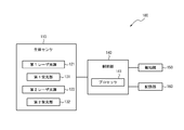
- FIG. 1 is a functional block diagram showing a schematic configuration of the measuring apparatus 100 according to the first embodiment.
- the measurement apparatus 100 according to the present embodiment includes a biosensor 110, a control unit 140, a notification unit 150, and a storage unit 160.
- the measuring apparatus 100 uses the biosensor 110 to acquire a biometric output of a subject (user) that contacts the measuring apparatus 100 and measures biometric information based on the biometric output.
- the measuring apparatus 100 according to the present embodiment can measure the oxygen saturation and blood flow rate of the subject using the biosensor 110.
- the measurement apparatus 100 according to the present embodiment uses, for example, percutaneous arterial oxygen saturation (SpO 2 , S: Saturation), P: Percutaneous (transcutaneous) as values indicating the oxygen saturation of the subject. ) Or Pulse Oximetry (O 2 : Oxygen (oxygen)).
- SpO 2 percutaneous arterial oxygen saturation
- P Percutaneous (transcutaneous)
- Pulse Oximetry O 2 : Oxygen (oxygen)
- the biological information measured by the measuring apparatus 100 is not necessarily limited to SpO 2 and blood flow volume.
- the measuring apparatus 100 may measure any biological information that can be measured using the biological sensor 110.
- SaO 2 percutaneous arterial oxygen saturation
- S Saturation (saturation)
- a artery (artery)
- O 2 Oxygen (oxygen)
- SpO 2 is a method of indirectly measuring SaO 2 , and if the measurement conditions are in place, both take recent values.
- the biosensor 110 acquires a biometric output from the test portion of the subject that contacts the measuring device 100.
- the test site is an arbitrary site from which a biometric output can be acquired, and in the present embodiment, the test site will be described below as a finger.
- the site to be examined may be a finger, an arm, an ear, a forehead, a neck, a back, a foot, and other parts together with a finger, or a part arbitrarily combining these parts.
- the biosensor 110 includes a light emitting unit and a light receiving unit.
- the biosensor 110 includes a first laser light source 121 and a second laser light source 122 as light emitting units.
- the biosensor 110 includes a first light receiving unit 131 and a second light receiving unit 132 as light receiving units.
- the first laser light source 121 and the second laser light source 122 emit laser light having a wavelength capable of detecting a predetermined component contained in blood as measurement light.
- the first laser light source 121 and the second laser light source 122 are each configured by, for example, an LD (Laser Diode).
- a vertical cavity surface emitting laser (VCSEL: vertical cavity surface emitting laser) is used as a laser light source.
- VCSEL vertical cavity surface emitting laser
- DFB distributed feedback laser
- FP Perot type laser
- the first laser light source 121 and the second laser light source 122 each emit laser beams having different wavelengths.
- the first laser light source 121 emits laser light having a first wavelength (hereinafter also referred to as “first laser light”).
- the first wavelength is a wavelength having a large difference between the absorbance of hemoglobin bound to oxygen (hereinafter also referred to as “oxygenated hemoglobin”) and the absorbance of hemoglobin not bound to oxygen (hereinafter also referred to as “reduced hemoglobin”).
- the first wavelength is, for example, a wavelength from 600 nm to 700 nm, and the first laser light is so-called red light. In the present embodiment, the following description will be made assuming that the first wavelength is 660 nm.
- the second laser light source 122 emits laser light having a second wavelength (hereinafter also referred to as “second laser light”).
- the second wavelength is a wavelength different from the first wavelength.
- the second wavelength is a wavelength in which the difference between the absorbance of oxygenated hemoglobin and the absorbance of reduced hemoglobin is small compared to the first wavelength.
- the second wavelength is, for example, a wavelength of 800 nm to 1000 nm, and the second laser light is so-called near infrared light. In the present embodiment, the following description will be made assuming that the second wavelength is 850 nm.
- the first light receiving unit 131 and the second light receiving unit 132 receive the scattered light (detection light) scattered from the test site of the measurement light applied to the test site as the biometric output.
- the first light receiving unit 131 and the second light receiving unit 132 are each configured by, for example, a PD (photodiode).
- the biological sensor 110 transmits a photoelectric conversion signal of scattered light received by the first light receiving unit 131 and the second light receiving unit 132 to the control unit 140.
- FIG. 2 is a schematic diagram for explaining an example of the usage state of the measuring apparatus 100.
- the measuring apparatus 100 measures biological information in a state where the subject is in contact with a specific position (measurement unit) in the measuring apparatus 100.
- the measuring apparatus 100 may measure the biological information in a state where the subject does not contact the test site at a specific position (measurement unit) in the measuring apparatus 100.
- the first light receiving unit 131 receives the scattered light from the test site of the first laser light emitted from the first laser light source 121.
- the first light receiving unit 131 may be configured by a PD capable of detecting light having a wavelength of scattered light of the first laser light (red light).
- the second light receiving unit 132 receives the scattered light from the test site of the second laser light emitted from the second laser light source 122.
- the second light receiving unit 132 may be configured by a PD that can detect light having the wavelength of the scattered light of the second laser light (near infrared light).
- the first light receiving unit 131 and the second light receiving unit 132 are arranged in the measurement apparatus 100 at positions where the scattered light of the laser light emitted from the first laser light source 121 and the second laser light source 122 can be received, respectively.
- Reduced hemoglobin easily absorbs the first laser light that is red light, and hardly absorbs the second laser light that is near-infrared light.
- oxygenated hemoglobin is difficult to absorb both the first laser light that is red light and the second laser light that is near-infrared light. That is, the first laser light that is red light is easily absorbed by reduced hemoglobin and is not easily absorbed by oxygenated hemoglobin.
- the second laser light which is near-infrared light, is difficult to be absorbed by reduced hemoglobin and oxygenated hemoglobin.
- the first laser beam is mainly absorbed by reduced hemoglobin and scattered by oxygenated hemoglobin. Therefore, the received light intensity of the scattered light of the first laser light as the biometric output received by the first light receiving unit 131 is due to the amount of oxygenated hemoglobin.
- the second laser light is scattered by reduced hemoglobin and oxygenated hemoglobin. Therefore, the received light intensity of the scattered light of the second laser light as the biometric output received by the second light receiving unit 132 is due to the total amount of hemoglobin including reduced hemoglobin and oxygenated hemoglobin.
- control unit 140 includes at least one processor 141 that controls and manages the entire measurement apparatus 100 including each functional block of the measurement apparatus 100.
- the control unit 140 includes at least one processor 141 such as a CPU (Central Processing Unit) that executes a program that defines a control procedure, and realizes its function.
- a program is stored in, for example, the storage unit 160 or an external storage medium connected to the measurement apparatus 100.
- the at least one processor 141 is implemented as a single integrated circuit (IC) or as a plurality of communicatively connected integrated circuits ICs and / or discrete circuits (discrete circuits). Also good.
- the at least one processor 141 can be implemented according to various known techniques.
- the processor 141 includes one or more circuits or units configured to perform one or more data computation procedures or processes, for example, by executing instructions stored in associated memory.
- the processor 141 may be firmware (eg, a discrete logic component) configured to perform one or more data computation procedures or processes.
- the processor 141 may include one or more processors, controllers, microprocessors, microcontrollers, application specific integrated circuits (ASICs), digital signal processors, programmable logic devices, field programmable gate arrays, or the like. Any combination of these devices or configurations, or other known devices or configuration combinations may be included, and the function as the control unit 140 described below may be executed.
- ASICs application specific integrated circuits
- the control unit 140 calculates a value related to each blood flow rate based on outputs from the first light receiving unit 131 and the second light receiving unit 132 (that is, photoelectric conversion signals of scattered light).
- a value based on the output from the first light receiving unit 131 is referred to as a first value
- a value based on the output from the second light receiving unit 132 is referred to as a second value.
- the control unit 140 can calculate the first value and the second value using the Doppler shift.
- the control unit 140 When the control unit 140 measures the first value and the second value, the control unit 140 emits laser light from the light emitting unit (that is, the first laser light source 121 and the second laser light source 122) into the tissue of the living body, and receives the light receiving unit. (Ie, the first light receiving unit 131 and the second light receiving unit 132) receive the scattered light scattered from the living tissue. And the control part 140 calculates a 1st value and a 2nd value based on the measurement result of the received laser beam.
- the light emitting unit that is, the first laser light source 121 and the second laser light source 122
- the control unit 140 receives the scattered light scattered from the living tissue.
- the control part 140 calculates a 1st value and a 2nd value based on the measurement result of the received laser beam.
- the control unit 140 detects a beat signal (also referred to as a beat signal) generated by light interference between scattered light from a stationary tissue and scattered light from a moving blood cell.
- This beat signal represents the intensity as a function of time.
- the control part 140 makes this beat signal the power spectrum which represented power as a function of frequency.
- the Doppler shift frequency is proportional to the blood cell velocity, and the power corresponds to the amount of blood cells. Then, the control unit 140 calculates the first value and the second value by integrating the power spectrum of the beat signal over the frequency.
- the second value P2 K ⁇ ⁇ f ⁇ P (f) df / (I ⁇ I)
- P2 ⁇ f ⁇ P (f) df / (I ⁇ I)
- the first value indicates a value based on the flow rate of oxygenated hemoglobin.
- the second value indicates a value based on the flow rate of the entire hemoglobin in the blood. Since the value calculated based on the flow rate of the entire hemoglobin in the blood is the blood flow rate of the subject, the second value indicates the blood flow rate of the subject. Therefore, the control unit 140 can calculate the blood flow rate of the subject by calculating the second value. In this way, the measuring device 100 can measure the blood flow of the subject.
- the control unit 140 calculates the subject's SpO 2 based on the first value and the second value.
- the control unit 140 can calculate SpO 2 based on the ratio of the first value to the second value.
- SpO 2 is calculated by the mathematical formula ⁇ HbO 2 / (Hb + HbO 2 ) ⁇ ⁇ 100 when the amount of oxygenated hemoglobin is HbO 2 and the amount of reduced hemoglobin is Hb (see, for example, Patent Document 1).
- HbO 2 represents the amount of oxygenated hemoglobin
- Hb + HbO 2 represents the sum of the amounts of oxygenated hemoglobin and reduced hemoglobin.
- HbO 2 can be associated with the first value calculated based on the flow rate of oxygenated hemoglobin, and (Hb + HbO 2 ) is calculated based on the total flow rate of hemoglobin in the blood. Can be associated with the second value. Accordingly, in the above equation, replace HbO 2 to a first value, when the (Hb + HbO 2) was replaced by the second value, the index showing the SpO 2 is for example, (first value / second value) It can be calculated by a mathematical formula of ⁇ 100. In the present embodiment, the control unit 140 calculates an index indicating SpO 2 using a mathematical formula of (first value / second value) ⁇ 100.
- the measuring apparatus 100 can measure the subject's SpO 2 .
- it is an index indicating SpO 2 that can be calculated by a mathematical formula of (first value / second value) ⁇ 100.
- (first value / second value) ⁇ 100 may be set as SpO 2 as it is, or the value of (first value / second value) is multiplied by a predetermined weighting operation, for example, a coefficient.
- the value obtained by the calculation may be the SpO 2
- Control unit 140 is further based on the blood flow and SpO 2 of calculated subject may estimate the likelihood that the subject is altitude sickness (also called disability). Altitude sickness is likely to develop when SpO 2 decreases or dehydration tends to occur. When the subject has a tendency to dehydrate, there is a case where water in the blood is insufficient and blood flow is deteriorated (blood flow volume is reduced). Control unit 140, based on the change in the blood flow and the SpO 2, can be estimated the likelihood that the subject is altitude sickness. The control unit 140 may estimate the possibility of altitude sickness, for example, by weighting the blood flow rate and SpO 2 using a predetermined algorithm.
- the measuring apparatus 100 since it is possible to measure the SpO 2 and blood flow rate, based on two indices of SpO 2 and blood flow rate, it can be estimated the potential to be altitude sickness. Therefore, according to the measuring apparatus 100 according to this embodiment, as compared with the case of estimating the possibility of altitude sickness only SpO 2, increases the accuracy of estimating the possibility of altitude sickness.
- the notification unit 150 notifies information using sound, vibration, images, and the like.
- the notification unit 150 may include a speaker, a vibrator, and a display device.
- the display device can be, for example, a liquid crystal display (LCD), an organic EL display (OELD), an inorganic EL display (IELD), or an organic EL-Luminescence Display.
- Notification unit 150 may notify the example SpO 2 and / or blood flow measurement of.
- reporting part 150 may alert
- the storage unit 160 can be configured by a semiconductor memory, a magnetic memory, or the like.
- the storage unit 160 stores various information or a program for operating the measurement apparatus 100.
- the storage unit 160 may function as a work memory.
- the storage unit 160 may store, for example, the subject's SpO 2 and blood flow calculated by the control unit 140 as history information.
- the control unit 140 may repeatedly execute the flow illustrated in FIG. 3 when the measurement apparatus 100 is activated or when a predetermined operation input for starting the measurement process is performed.
- the control unit 140 has a function capable of detecting whether or not the test site is in contact with the measurement unit
- the control unit 140 illustrated in FIG. 3 determines that the test site is in contact with the measurement unit.
- a flow may be executed.
- the controller 140 emits the first laser light from the first laser light source 121 (step S101).
- the control unit 140 emits the second laser light from the second laser light source 122 (step S102).
- the first light receiving unit 131 and the second light receiving unit 132 receive the scattered light from the test site, respectively.
- the first light receiving unit 131 and the second light receiving unit 132 transmit the photoelectric conversion signal of the scattered light to the control unit 140.
- the control unit 140 acquires outputs from the first light receiving unit 131 and the second light receiving unit 132 (step S103).
- the control unit 140 calculates a first value based on the output acquired from the first light receiving unit 131, and calculates a second value based on the output acquired from the second light receiving unit 132 (step S104). .
- Control unit 140 based on the first value and second value calculated in step S104, and calculates an index indicating the SpO 2, and calculates the SpO 2 from the index shown in SpO 2 (step S105).
- the control unit 140 estimates the possibility that the subject will suffer from altitude sickness based on the blood flow rate (that is, the second value) and SpO 2 (step S106).
- the control unit 140 notifies the information such as the calculated blood flow volume and SpO2 and the possibility of becoming an altitude sickness from the notification unit 150 (step S107).
- the measuring apparatus 100 emits laser light to the test site, and the first value and the second value are based on the received light intensity of the scattered light of the laser light from the test site. And calculate.
- the measuring apparatus 100 calculates SpO 2 based on the first value and the second value.
- the laser beam is used for obtaining the biometric measurement output. Since the laser light has high directivity and has the same wavelength and phase, the measurement apparatus 100 has a higher measurement accuracy of SpO 2 than the case of using light of a wide wavelength band, for example, which is not laser light. improves. Thus, according to the measuring apparatus 100, usability improves.
- the blood flow rate and SpO 2 can be measured with one apparatus. Therefore, there is no need to measure the blood flow volume and SpO 2 with separate devices, and convenience and usefulness are increased by the subject.
- FIG. 4 is a functional block diagram showing a schematic configuration of the measuring apparatus 200 according to the second embodiment.
- the measuring apparatus 200 according to the present embodiment includes a biological sensor 210, a control unit 240, a notification unit 250, and a storage unit 260.
- the biological sensor 110 includes two light receiving parts, the first light receiving part 131 and the second light receiving part 132, whereas the measuring apparatus 200 according to the second embodiment is a living body. It differs from the measuring apparatus 100 according to the first embodiment in that the sensor 210 includes only one light receiving unit 230.
- the biosensor 210 includes two light emitting units, the first laser light source 221 and the second laser light source 222, and one light receiving unit 230.
- the functions of the first laser light source 221 and the second laser light source 222 are the same as those of the first laser light source 121 and the second laser light source 122 in the first embodiment, respectively. That is, the first laser light source 221 emits the first laser light, and the second laser light source 222 emits the second laser light.
- the first laser light source 221 and the second laser light source 222 emit the first laser light and the second laser light at different timings.
- the first laser light source 221 and the second laser light source 222 alternately output laser light. That is, in the measurement process by the measuring apparatus 200, the first laser beam and the second laser beam are alternately emitted to the test site, for example, every predetermined time.
- the light receiving unit 230 is configured by, for example, a so-called multi-frequency compatible PD capable of detecting light having a wavelength of scattered light of both the first laser light (red light) and the second laser light (near infrared light). The Therefore, the light receiving unit 230 detects the scattered light of the first laser light when the first laser light is emitted to the test site, and when the second laser light is emitted to the test site, Scattered light of the second laser light is detected.
- the biosensor 210 transmits a photoelectric conversion signal of scattered light received by the light receiving unit 230 to the control unit 240.
- FIG. 5 is a schematic diagram for explaining an example of a usage state of the measuring apparatus 200.
- the light receiving unit 230 receives the scattered light from the test site of the first laser light emitted from the first laser light source 221 and the first laser light emitted from the second laser light source 222. Two laser beams scattered light from the test site is received. Since the first laser light and the second laser light are alternately emitted as described above, the light receiving unit 230 receives the scattered light alternately. Accordingly, FIG. 5 shows the first laser beam, the second laser beam, and the scattered light thereof, but in actuality, at any point in time, either the first laser beam or the second laser beam is covered. The light receiving unit emits scattered light of the emitted laser light. In the measuring apparatus 200, the light receiving unit 230 is disposed at a position where the scattered light of the laser light emitted from the first laser light source 221 and the second laser light source 222 can be received.
- control unit 240 includes at least one processor 241 that controls and manages the entire measurement apparatus 200 including each functional block of the measurement apparatus 200.
- the functions of the control unit 240 and the processor 241 are the same as those of the control unit 140 and the processor 141 of the first embodiment, respectively, and thus detailed description thereof is omitted here. Since the functions of the notification unit 250 and the storage unit 260 are also the same as those of the notification unit 150 and the storage unit 160 of the first embodiment, detailed description thereof is omitted here.
- the blood flow volume and SpO 2 are measured by the control unit 240 according to the same flow as that described with reference to FIG. 3, and the possibility of the subject becoming altitude sickness is estimated.
- the control unit 240 acquires the output from the light receiving unit 230 in step S103.
- the control unit 240 determines whether the acquired output from the light receiving unit 230 is scattered light of the first laser or scattered light of the second laser light. Calculate the value.
- the measuring apparatus 200 since the measuring apparatus 200 according to the present embodiment also calculates the SpO 2 by emitting the laser beam to the test site, for example, compared to the case where light in a wide wavelength band is used, the measurement accuracy of the SpO 2 Will improve. Thus, according to the measuring apparatus 200, usability improves.
- the measuring apparatus 200 according to the present embodiment can receive the scattered light of the first laser light and the second laser light with one light receiving unit 230 that supports multi-frequency. Therefore, the biosensor 210 and the measuring apparatus 200 can be reduced in size compared to the case where the scattered light of the first laser light and the second laser light is received by two different light receiving units.
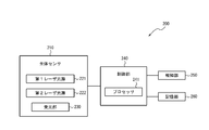
- FIG. 6 is a functional block diagram illustrating a schematic configuration of a measurement system 300 according to the third embodiment.
- the measurement system 300 includes a measurement device 400, an information processing device 500, and a terminal device 600.
- the information processing apparatus 500 is communicably connected to the measurement apparatus 400 and the terminal apparatus 600 by wired, wireless, or a combination of wired and wireless.
- the measurement device 400 and the terminal device 600 may be able to communicate directly.
- the network that connects the measuring device 400, the information processing device 500, and the terminal device 600 to each other may be the Internet or a wireless LAN.
- the measuring device 400 is a device that measures a biometric output by injecting laser light to a region to be examined.
- the measurement apparatus 400 may transmit information regarding the measured biometric measurement output to the information processing apparatus 500.
- the information processing apparatus 500 can be configured as a server apparatus such as a computer.
- the information processing apparatus 500 may calculate the blood flow volume and SpO 2 of the subject based on information on the biometric measurement output acquired from the measurement apparatus 400.
- the information processing apparatus 500 may estimate the possibility that the subject will suffer from altitude sickness.
- the information processing apparatus 500 may store information related to the blood flow volume and the calculation result of SpO 2 and the estimated possibility of becoming an altitude sickness.
- the information processing apparatus 500 may transmit information regarding the blood flow volume and the SpO 2 calculation result and the estimated possibility of becoming an altitude sickness to the terminal apparatus 600.
- the terminal device 600 may be configured as a personal computer, a smartphone, a tablet, or the like, for example.
- the terminal device 600 may be owned by the subject, for example.
- the terminal device 600 may perform notification based on the blood flow obtained from the information processing device 500, the calculation result of SpO 2 , and information regarding the estimated possibility of becoming an altitude sickness.
- the measuring apparatus 400 includes a biological sensor 410, a control unit 440, a notification unit 450, and a storage unit 460.
- the biological sensor 410 includes a first laser light source 421, a second laser light source 422, a first light receiving unit 431, and a second light receiving unit 432.
- the functions of the first laser light source 421, the second laser light source 422, the first light receiving unit 431, and the second light receiving unit 432 are the first laser light source 121, the second laser light source 122, and the first light receiving unit in the first embodiment, respectively. 131 and the second light receiving unit 132.
- the measurement apparatus 400 in the present embodiment can acquire a biometric output in the same manner as the measurement apparatus 100 in the first embodiment.
- the control unit 440 includes at least one processor 441 that controls and manages the entire measurement apparatus 400 including each functional block of the measurement apparatus 400.
- the control unit 440 includes at least one processor 441 such as a CPU that executes a program that defines a control procedure, and realizes its function. Such a program is stored in, for example, the storage unit 460 or an external storage medium connected to the measurement apparatus 400.
- the processor 441 may have the same configuration as that of the processor 441 shown in the first embodiment, for example, and detailed description thereof is omitted here.
- the control unit 440 controls acquisition of the biological measurement output by the biological sensor 410 and transmits information related to the acquired biological measurement output to the information processing apparatus 500 via the communication unit 470.
- the storage unit 460 can be composed of a semiconductor memory or a magnetic memory.
- the storage unit 460 stores various information and / or a program for operating the measurement apparatus 400.
- the storage unit 460 may function as a work memory.
- the storage unit 460 may store data such as information related to the biological measurement output acquired by the biological sensor 410 (that is, the received light intensity of scattered light).
- the communication unit 470 performs transmission / reception of various information by performing wired communication or wireless communication with the information processing device 500 or a combination of wired communication and wireless communication.
- the communication unit 570 transmits information related to the biometric measurement output measured by the measurement apparatus 400 to the information processing apparatus 500.
- the information processing apparatus 500 includes a control unit 540, a storage unit 560, and a communication unit 570.
- the control unit 540 includes at least one processor 541 that controls and manages the entire information processing apparatus 500 including each functional block of the information processing apparatus 500.
- the control unit 540 includes at least one processor 541 such as a CPU that executes a program that defines a control procedure, and realizes its function. Such a program is stored in, for example, the storage unit 560 or an external storage medium connected to the information processing apparatus 500.
- the processor 541 may have a configuration similar to that of the processor 141 shown in the first embodiment, for example, and thus detailed description thereof is omitted here.
- the control unit 540 may calculate the blood flow rate and SpO 2 of the subject based on the information related to the biological measurement output acquired from the measurement device 400.
- the control unit 540 may estimate the possibility that the subject will have altitude sickness.
- the details of the blood flow volume and SpO 2 calculation method by the control unit 540 and the details of the estimation method for the possibility of becoming an altitude sickness are the same as those described in the first embodiment, and thus the description thereof is o
- the storage unit 560 can be configured by a semiconductor memory, a magnetic memory, or the like.
- the storage unit 560 stores various information and / or a program for operating the information processing apparatus 500.
- the storage unit 560 may function as a work memory.
- storage part 560 may memorize
- Storage unit 560 calculates the blood flow and SpO 2 by the control unit 540, as well as various information used to estimate the possibility of altitude sickness may be stored.
- the communication unit 570 transmits and receives various types of information by performing wired communication or wireless communication or a combination of wired communication and wireless communication with the measurement apparatus 400 and the terminal device 600.
- the communication unit 570 receives information related to biometric output from the measurement device 400.
- the communication unit 570 transmits the blood flow volume and SpO 2 calculated by the information processing apparatus 500 and information related to the possibility of altitude sickness to the terminal device 600.
- the terminal device 600 includes a control unit 640, a notification unit 650, a storage unit 660, a communication unit 670, and an input unit 680.
- the control unit 640 includes at least one processor 641 that controls and manages the entire terminal device 600 including each functional block of the terminal device 600.
- the control unit 640 includes at least one processor 641 such as a CPU that executes a program that defines a control procedure, and realizes its function. Such a program is stored in the storage unit 660 or an external storage medium connected to the terminal device 600, for example.
- the processor 641 may have the same configuration as that of the processor 141 shown in the first embodiment, for example, and detailed description thereof is omitted here.
- the control unit 640 may notify the information regarding the blood flow volume and SpO 2 acquired from the information processing apparatus 500 and the possibility of becoming an altitude sickness from the notification unit 650.
- the notification unit 650 notifies information using sound, vibration, images, and the like. Since the function and configuration of the notification unit 650 may be the same as those of the notification unit 150 described in the first embodiment, detailed description thereof is omitted here.
- the storage unit 660 can be configured by a semiconductor memory, a magnetic memory, or the like.
- the storage unit 660 stores various information and / or programs for operating the terminal device 600.
- the storage unit 660 may function as a work memory.
- Storage unit 660 for example, blood flow and SpO 2 acquired from the information processing apparatus 500, and may store information about the possibility of altitude sickness.
- the communication unit 670 transmits and receives various types of information by performing communication with the information processing apparatus 500 by wired communication or wireless communication, or a combination of wired communication and wireless communication. For example, the communication unit 670 receives information regarding the blood flow rate, SpO 2 , and the possibility of becoming an altitude sickness from the information processing apparatus 500.
- the input unit 680 receives an operation input from a user (for example, a subject) of the terminal device 600 and includes, for example, an operation button (operation key).
- the input unit 680 may be configured by a touch panel, and an operation key that receives an operation input from the user may be displayed on a part of the display device to receive a touch operation input by the user.
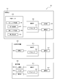
- FIG. 7 is a sequence diagram illustrating an example of a control procedure performed by the measurement system 300.
- the process illustrated in FIG. 7 is executed, for example, when the measurement apparatus 400 is activated or when a predetermined operation input for starting the measurement process is performed.
- the control unit 440 of the measurement apparatus 400 has a function capable of detecting whether or not the test site is in contact with the measurement unit, when it is determined that the test site is in contact with the measurement unit, The process shown in FIG. 7 may be executed.
- the measuring apparatus 400 emits the first laser light from the first laser light source 421 (step S201).
- the measuring apparatus 400 emits the second laser light from the second laser light source 422 (step S202).
- the measuring apparatus 400 acquires biometric measurement outputs from the first light receiving unit 431 and the second light receiving unit 432 (step S203).
- the measuring apparatus 400 transmits information related to the biometric measurement output to the information processing apparatus 500 via the communication unit 470 (step S204).
- the information processing apparatus 500 acquires information related to the biometric measurement output from the measurement apparatus 400, the information processing apparatus 500 calculates the first value and the second value based on the biometric output (step S205).
- the information processing apparatus 500 calculates SpO 2 based on the first value and the second value calculated in step S205 (step S206).
- the information processing apparatus 500 estimates the possibility that the subject will have altitude sickness based on the blood flow rate (that is, the second value) and SpO 2 (step S207).
- the information processing apparatus 500 transmits information such as the blood flow volume, SpO2, and the possibility of altitude sickness to the terminal apparatus 600 via the communication unit 570 (step S208).
- the terminal device 600 When the terminal device 600 acquires information such as the blood flow rate and SpO 2 , and the possibility of becoming an altitude sickness from the information processing device 500, the terminal device 600 obtains information such as the blood flow rate and SpO 2 and the possibility of becoming an altitude sickness. Then, the notification is made from the notification unit 650 (step S209).
- the biosensor 410 of the measurement apparatus 400 has the same configuration as the biosensor 110 of the first embodiment has been described.
- the biosensor 410 may have the same configuration as the biosensor 210 of the second embodiment.
- the information processing apparatus 500 calculates the blood flow volume and SpO 2 and estimates the possibility of becoming altitude sickness.
- the measurement apparatus 200 calculates the blood flow volume and SpO 2 , and Takayama. You may perform the estimation process of the possibility of becoming sick.
- the measurement apparatus 400 may transmit the blood flow volume and the SpO 2 calculation result, and the estimation result of the possibility of becoming altitude sickness to the information processing apparatus 500.
- the measurement system 300 may not include the information processing apparatus 500.
- the measurement apparatus 400 may transmit the blood flow volume and the SpO 2 calculation result and the estimation result of the possibility of becoming altitude sickness to the terminal apparatus 600.
- the SpO 2 is calculated by emitting the laser light to the test site, and therefore, for example, SpO 2 is compared with a case where light in a wide wavelength band is used. Improved measurement accuracy. Thus, according to the measurement system 300, usability is improved.
- the measurement devices (measurement devices 100, 200, and 400) described in the above embodiments can be mounted on various devices.
- the measuring device 100, 200, or 400 may be mounted on a cerebral blood flow meter that measures cerebral blood flow.
- a cerebral blood flow meter is a device that measures cerebral blood flow by emitting laser light to the brain.
- a subject uses a band-shaped measurement member wrapped around the head.
- the measuring device 100, 200 or 400 may be mounted on a measuring member.
- the subject activates the cerebral blood flow meter 700 with the measurement member of the cerebral blood flow meter 700 wound around the head.
- the measuring device 100, 200 or 400 can be activated.
- the subject can simultaneously perform measurement of cerebral blood flow and measurement of blood flow and SpO 2 .
- the cerebral blood flow meter 700 can estimate the possibility of the subject having altitude sickness based on the measured cerebral blood flow, blood flow rate, and SpO 2 .
- the cerebral blood flow meter 700 can estimate the possibility of the subject having altitude sickness based on the measured cerebral blood flow, blood flow rate, and SpO 2 .
- the measuring device 100, 200, or 400 may be mounted on a sphygmomanometer that measures blood pressure.
- the sphygmomanometer may be, for example, a well-known upper arm sphygmomanometer that measures blood pressure with the upper arm using a cuff (arm band).
- the sphygmomanometer 800 is used by the subject with the cuff wrapped around the upper arm.
- the measuring device 100, 200 or 400 may be mounted on the cuff.
- the subject When the measuring device 100, 200, or 400 is mounted on the sphygmomanometer 800, the subject activates the sphygmomanometer 800 with the cuff wrapped around the upper arm, and activates the measuring device 100, 200, or 400. can do. As a result, the subject can simultaneously perform blood pressure measurement and blood flow volume and SpO 2 measurement. In this case, the blood pressure meter 800, the measured blood pressure, based on the blood flow and SpO 2, can be estimated the likelihood that the subject is altitude sickness. Thus, as compared with the case of estimating the possibility of altitude sickness only SpO 2, increases the estimation accuracy.
- the measuring device 100, 200, or 400 may be mounted on a thermometer that measures body temperature.
- the thermometer 900 measures the skin temperature by bringing it into contact with the human skin.
- the subject may activate the measuring device 100, 200, or 400 when measuring the body temperature by bringing the thermometer 900 into contact with the skin. it can.
- the subject can simultaneously perform measurement of body temperature and measurement of blood flow and SpO 2 .
- the thermometer 900, the measured temperature on the basis of the blood flow and SpO 2 can be estimated the likelihood that the subject is altitude sickness.
- the measuring device 100, 200 or 400 may be mounted on a device capable of measuring information related to a living body other than the cerebral blood flow meter 700, the sphygmomanometer 800 and the thermometer 900.
- the control unit of each embodiment has been described as estimating the possibility that the subject will suffer from altitude sickness based on the blood flow rate and SpO 2. However, the control unit of each embodiment is configured to calculate the blood flow rate and SpO 2 . Based on at least one of them, other symptoms such as blood pressure, dehydration, relaxed state, autonomic state, and heart disease may be detected.
- the test site is described as being a finger, but the test site is not necessarily a finger.
- the test site may be a wrist, an arm, an ear, a forehead, a neck, a back, a foot, or other sites, or a site where these are arbitrarily combined.
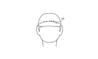
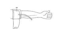
- FIG. 11 is a diagram schematically illustrating an example of a mounting state of a measuring instrument 1000 including a measuring device that uses a temple as a test site.
- the measuring instrument 1000 includes two holding parts 1001 and a headband 1002 that couples the two holding parts 1001.
- the two holding parts 1001 maintain the wearing state by contacting the left and right temples of the subject, respectively, in the wearing state of the measuring instrument 1000.
- the holding part 1001 may have a shape that does not block the subject's ear when the measuring instrument 1000 is mounted.
- the holding part 1001 may have a structure that contacts the temple at the upper side of the ear. In this case, since the subject's ear is not blocked even when the measuring instrument 1000 is attached, the subject can hear surrounding sounds. Therefore, it becomes easier to ensure the safety of the subject as compared to the case where the ear of the subject is blocked.
- the headband 1002 may have an arch shape, for example, as shown in FIG.
- the measuring instrument 1000 is attached to the subject so that the headband 1002 is located on the top of the head, for example.
- the headband 1002 may have a mechanism whose length can be adjusted according to the size of the subject's head, for example.
- the headband 1002 may be configured by a member having rigidity such as stainless steel or carbon fiber.
- the headband 1002 may maintain the wearing state by pressing the two holding portions 1001 toward the human body in the wearing state of the measuring instrument 1000.
- At least one of the two holding units 1001 includes a measuring device.
- the measuring device provided in the holding unit 1001 may be, for example, any of the measuring devices described in the first to third embodiments.
- maintenance part 1001 is demonstrated below, provided with the measuring apparatus 200 demonstrated in 2nd Embodiment.
- FIG. 12 is a partial cross-sectional view of the measurement instrument 1000 shown in FIG. 11, and is a cross-sectional view schematically showing a holding unit 1001 including the measurement device 200.
- the holding unit 1001 includes a measurement device 200.
- the measurement device 200 includes the first laser light source 221, the second laser light source 222, and the light receiving unit 230.
- laser light emitted from the first laser light source 221 and the second laser light source 222 is applied to the superficial temporal artery.
- the light receiving unit 230 receives scattered light with respect to measurement light in the superficial temporal artery.
- the blood flow rate and SpO 2 are calculated using scattered light in the superficial temporal artery. Since the blood vessels of the superficial temporal artery are thicker than blood vessels such as fingertips, it is easier to obtain biological information. Since blood vessels in the superficial temporal artery are thicker than blood vessels such as fingertips, the blood flow is more stable. Therefore, more accurate blood flow and SpO 2 can be measured by irradiating the superficial temporal artery with measurement light and acquiring biological information.
- the measuring apparatus 200 may be connected to the headband 1002 via the connection unit 1003.
- the connection unit 1003 functions as a reduction unit that reduces vibration transmitted from the headband 1002 to the measurement apparatus 200.
- the connection unit 1003 functions as a damper, for example.
- the connection portion 1003 may be configured to include an elastic material that can reduce vibration.
- the connecting portion 1003 may be configured by a spring, rubber, silicone resin, gel, cloth, sponge, paper, other members, or any combination thereof.
- the connection unit 1003 may be a fluid-filled damper having a fluid (that is, liquid or gas) inside, for example.
- the internal fluid may be, for example, a viscous liquid.
- the measuring device included in the holding unit 1001 is not limited to the measuring device 200 described in the second embodiment, and may be, for example, the measuring device 100 described in the first embodiment.
- One of the two holding units 1001 includes the first laser light source 121 and the first light receiving unit 131 described in the first embodiment, and the other includes the second laser light source 122 and the first laser light source 122 described in the first embodiment. 2 light receiving units 132 may be provided.
- the biological sensor emits laser light from two laser light sources, the first laser light source and the second laser light source.
- one of the first laser light source and the second laser light source may be constituted by a light source other than the laser light source, such as an LED (Light Emitting Diode).
- the LED light source When an LED light source is used instead of the first laser light source, the LED light source emits red light.
- the LED light source emits near-infrared light.
- the control unit calculates the first value P1 based on the amount of light received by the first light receiving unit with respect to the amount of light emitted from the LED light source. .
- the relationship between the ratio of the amount of received light to the amount of emitted light and the first value P1 may be stored in advance in the storage unit as a table, for example. The control unit can calculate the first value P1 with reference to the table.
Abstract
A measurement device is provided with: a first laser light source that emits laser light of a first wavelength; a second laser light source that emits laser light of a second wavelength differing from the first wavelength; a light-receiving unit that receives scattered laser light from a site to be examined; and a control unit that calculates a first value on the basis of output from the light-receiving unit based on received scattered laser light of the first wavelength, calculates a second value on the basis of output from the light-receiving unit based on received scattered laser light of the second wavelength, and measures oxygen saturation on the basis of the ratio of the first value to the second value.
Description
本出願は、日本国特許出願2017-044077号(2017年3月8日出願)、及び日本国特許出願2017-161545号(2017年8月24日出願)の優先権を主張するものであり、当該出願の開示全体を、ここに参照のために取り込む。
This application claims the priority of Japanese Patent Application No. 2017-044077 (filed on Mar. 8, 2017) and Japanese Patent Application No. 2017-161545 (filed on Aug. 24, 2017). The entire disclosure of that application is incorporated herein by reference.
本開示は、測定装置、測定方法及びプログラムに関する。
The present disclosure relates to a measurement apparatus, a measurement method, and a program.
従来、動脈血酸素飽和度を測定するパルスオキシメータが知られている(例えば、特許文献1参照)。従来、レーザ光を指先に照射し、指先の毛細血管の血流からの散乱光に基づいて血流を測定する血流測定装置が知られている(例えば、特許文献2参照)。
Conventionally, a pulse oximeter for measuring arterial blood oxygen saturation is known (see, for example, Patent Document 1). 2. Description of the Related Art Conventionally, a blood flow measurement apparatus that irradiates a fingertip with a laser beam and measures blood flow based on scattered light from blood flow of capillaries at the fingertip is known (see, for example, Patent Document 2).
測定装置の一態様は、第1レーザ光源と、第2レーザ光源と、受光部と、制御部とを備える。前記第1レーザ光源は、第1波長のレーザ光を射出する。前記第2レーザ光源は、前記第1波長と異なる第2波長のレーザ光を射出する。前記受光部は、被検部位からのレーザ光の散乱光を受光する。前記制御部は、前記第1波長のレーザ光の散乱光の受光に基づく前記受光部の出力に基づいて第1の値を算出し、前記第2波長のレーザ光の散乱光の受光に基づく前記受光部の出力に基づいて第2の値を算出し、前記第2の値に対する前記第1の値の割合に基づいて、酸素飽和度を測定する。
One aspect of the measuring apparatus includes a first laser light source, a second laser light source, a light receiving unit, and a control unit. The first laser light source emits laser light having a first wavelength. The second laser light source emits laser light having a second wavelength different from the first wavelength. The light receiving unit receives scattered light of laser light from a region to be examined. The control unit calculates a first value based on an output of the light receiving unit based on reception of scattered light of the laser light of the first wavelength, and the control unit calculates the first value based on reception of scattered light of the laser light of the second wavelength. A second value is calculated based on the output of the light receiving unit, and oxygen saturation is measured based on the ratio of the first value to the second value.
測定方法の一態様は、測定装置による測定方法である。前記測定方法は、被検部位に第1波長のレーザ光を射出するステップと、前記被検部位に前記第1波長と異なる第2波長のレーザ光を射出するステップと、前記被検部位からのレーザ光の散乱光を受光するステップと、を含む。前記測定方法は、前記第1波長のレーザ光の散乱光の受光に基づいて第1の値を算出するステップと、前記第2波長のレーザ光の散乱光の受光に基づいて第2の値を算出するステップと、前記第2の値に対する前記第1の値の割合に基づいて、酸素飽和度を測定するステップと、を含む。
* One aspect of the measuring method is a measuring method using a measuring device. The measurement method includes a step of emitting a laser beam having a first wavelength to a test site, a step of emitting a laser beam having a second wavelength different from the first wavelength to the test site, and a step from the test site. Receiving the scattered light of the laser beam. The measuring method includes a step of calculating a first value based on reception of scattered light of the laser light of the first wavelength, and a second value based on reception of scattered light of the laser light of the second wavelength. And calculating oxygen saturation based on a ratio of the first value to the second value.
プログラムの一態様は、コンピュータに、被検部位に第1波長のレーザ光を射出するステップと、前記被検部位に前記第1波長と異なる第2波長のレーザ光を射出するステップと、前記被検部位からのレーザ光の散乱光を受光するステップと、を実行させる。前記プログラムは、コンピュータに、前記第1波長のレーザ光の散乱光の受光に基づいて第1の値を算出するステップと、前記第2波長のレーザ光の散乱光の受光に基づいて第2の値を算出するステップと、前記第2の値に対する前記第1の値の割合に基づいて、酸素飽和度を測定するステップと、を実行させる。
One aspect of the program is a step of emitting a laser beam having a first wavelength to a test site, a step of emitting a laser beam having a second wavelength different from the first wavelength to the test site, Receiving the scattered light of the laser beam from the examination site. The program causes the computer to calculate a first value based on the reception of the scattered light of the laser light of the first wavelength, and to execute a second value based on the reception of the scattered light of the laser light of the second wavelength. A step of calculating a value, and a step of measuring oxygen saturation based on a ratio of the first value to the second value.
以下、実施形態について、図面を参照して詳細に説明する。
Hereinafter, embodiments will be described in detail with reference to the drawings.
(第1実施形態)
図1は、第1実施形態に係る測定装置100の概略構成を示す機能ブロック図である。本実施形態に係る測定装置100は、生体センサ110と、制御部140と、報知部150と、記憶部160とを備える。 (First embodiment)
FIG. 1 is a functional block diagram showing a schematic configuration of themeasuring apparatus 100 according to the first embodiment. The measurement apparatus 100 according to the present embodiment includes a biosensor 110, a control unit 140, a notification unit 150, and a storage unit 160.
図1は、第1実施形態に係る測定装置100の概略構成を示す機能ブロック図である。本実施形態に係る測定装置100は、生体センサ110と、制御部140と、報知部150と、記憶部160とを備える。 (First embodiment)
FIG. 1 is a functional block diagram showing a schematic configuration of the
測定装置100は、生体センサ110を使用して、測定装置100に接触する被検者(ユーザ)の生体測定出力を取得し、生体測定出力に基づいて生体情報を測定する。本実施形態に係る測定装置100は、生体センサ110を用いて、被検者の酸素飽和度及び血流量を測定できる。本実施形態に係る測定装置100は、被検者の酸素飽和度を示す値として、例えば経皮的動脈血酸素飽和度(SpO2、S:Saturation(サチュレーション・飽和度)、P:Percutaneous(経皮的)又はPulse Oximetry(パルスオキシメータ)、O2:Oxygen(酸素))を測定できる。ただし、測定装置100が測定する生体情報は、必ずしもSpO2及び血流量に限られない。測定装置100は、生体センサ110を使用して測定可能な任意の生体情報を測定してもよい。以下、本明細書では、経皮的動脈血酸素飽和度(SpO2)を単に酸素飽和度とも称する。酸素飽和度を示す値として、SaO2(S:Saturation(飽和度)、a:artery(動脈)、O2:Oxygen(酸素))があり、動脈血の酸素飽和度の実測値を示す。そして、SpO2は間接的にSaO2を測定する方法であり、測定条件が整っていれば、両者は近時値を取る。
The measuring apparatus 100 uses the biosensor 110 to acquire a biometric output of a subject (user) that contacts the measuring apparatus 100 and measures biometric information based on the biometric output. The measuring apparatus 100 according to the present embodiment can measure the oxygen saturation and blood flow rate of the subject using the biosensor 110. The measurement apparatus 100 according to the present embodiment uses, for example, percutaneous arterial oxygen saturation (SpO 2 , S: Saturation), P: Percutaneous (transcutaneous) as values indicating the oxygen saturation of the subject. ) Or Pulse Oximetry (O 2 : Oxygen (oxygen)). However, the biological information measured by the measuring apparatus 100 is not necessarily limited to SpO 2 and blood flow volume. The measuring apparatus 100 may measure any biological information that can be measured using the biological sensor 110. Hereinafter, percutaneous arterial oxygen saturation (SpO 2 ) is also simply referred to as oxygen saturation in this specification. SaO 2 (S: Saturation (saturation), a: artery (artery), O 2 : Oxygen (oxygen)) is a value indicating the oxygen saturation, and indicates an actual value of oxygen saturation of arterial blood. SpO 2 is a method of indirectly measuring SaO 2 , and if the measurement conditions are in place, both take recent values.
生体センサ110は、測定装置100に接触する被検者の被検部位から、生体測定出力を取得する。被検部位は、生体測定出力を取得可能な任意の部位であり、本実施形態では、指であるとして、以下説明する。被検部位は指に代え、又は指とともに、手首、腕、耳、額、首、背中及び足その他の部位又はこれらを任意に組み合わせた部位であってもよい。生体センサ110は、発光部と受光部とを備える。本実施形態において、生体センサ110は、発光部として、第1レーザ光源121及び第2レーザ光源122を備える。本実施形態において、生体センサ110は、受光部として、第1受光部131及び第2受光部132を備える。
The biosensor 110 acquires a biometric output from the test portion of the subject that contacts the measuring device 100. The test site is an arbitrary site from which a biometric output can be acquired, and in the present embodiment, the test site will be described below as a finger. The site to be examined may be a finger, an arm, an ear, a forehead, a neck, a back, a foot, and other parts together with a finger, or a part arbitrarily combining these parts. The biosensor 110 includes a light emitting unit and a light receiving unit. In the present embodiment, the biosensor 110 includes a first laser light source 121 and a second laser light source 122 as light emitting units. In the present embodiment, the biosensor 110 includes a first light receiving unit 131 and a second light receiving unit 132 as light receiving units.
第1レーザ光源121及び第2レーザ光源122は、血液中に含まれる所定の成分を検出可能な波長のレーザ光を測定光として射出する。第1レーザ光源121及び第2レーザ光源122は、例えばそれぞれLD(レーザダイオード:Laser Diode)により構成される。本実施形態ではレーザ光源として、垂直共振器型面発光レーザ(VCSEL:vertical cavity surface emitting laser)を用いるとして説明するが、レーザ光源としては、その他、分布帰還型レーザ(DFB:Distributed Feedback )、ファブリペロー型レーザ(FP:Fabry-Perot)を用いることができる。
The first laser light source 121 and the second laser light source 122 emit laser light having a wavelength capable of detecting a predetermined component contained in blood as measurement light. The first laser light source 121 and the second laser light source 122 are each configured by, for example, an LD (Laser Diode). In this embodiment, a vertical cavity surface emitting laser (VCSEL: vertical cavity surface emitting laser) is used as a laser light source. However, as a laser light source, a distributed feedback laser (DFB: distributed feedback) or a Fabry is used. A Perot type laser (FP: Fabry-Perot) can be used.
第1レーザ光源121及び第2レーザ光源122は、それぞれ異なる波長のレーザ光を射出する。第1レーザ光源121は、第1波長のレーザ光(以下「第1レーザ光」とも称する)を射出する。第1波長は、酸素と結合したヘモグロビン(以下「酸素化ヘモグロビン」とも称する)の吸光度と、酸素と結合していないヘモグロビン(以下「還元ヘモグロビン」とも称する)の吸光度との差分が大きい波長である。第1波長は、例えば600nmから700nmの波長であり、第1レーザ光は、いわゆる赤色光である。本実施形態では、第1波長が660nmであるとして以下説明する。第2レーザ光源122は、第2波長のレーザ光(以下「第2レーザ光」とも称する)を射出する。第2波長は、第1波長と異なる波長である。第2波長は、第1の波長と比べて、酸素化へモグロビンの吸光度と還元ヘモグロビンの吸光度との差分が小さい波長である。第2波長は、例えば800nmから1000nmの波長であり、第2レーザ光は、いわゆる近赤外光である。本実施形態では、第2波長が850nmであるとして以下説明する。
The first laser light source 121 and the second laser light source 122 each emit laser beams having different wavelengths. The first laser light source 121 emits laser light having a first wavelength (hereinafter also referred to as “first laser light”). The first wavelength is a wavelength having a large difference between the absorbance of hemoglobin bound to oxygen (hereinafter also referred to as “oxygenated hemoglobin”) and the absorbance of hemoglobin not bound to oxygen (hereinafter also referred to as “reduced hemoglobin”). . The first wavelength is, for example, a wavelength from 600 nm to 700 nm, and the first laser light is so-called red light. In the present embodiment, the following description will be made assuming that the first wavelength is 660 nm. The second laser light source 122 emits laser light having a second wavelength (hereinafter also referred to as “second laser light”). The second wavelength is a wavelength different from the first wavelength. The second wavelength is a wavelength in which the difference between the absorbance of oxygenated hemoglobin and the absorbance of reduced hemoglobin is small compared to the first wavelength. The second wavelength is, for example, a wavelength of 800 nm to 1000 nm, and the second laser light is so-called near infrared light. In the present embodiment, the following description will be made assuming that the second wavelength is 850 nm.
第1受光部131及び第2受光部132は、生体測定出力として、被検部位に照射された測定光の、被検部位から散乱される散乱光(検出光)を受光する。第1受光部131及び第2受光部132は、例えばそれぞれPD(フォトダイオード:Photo Diode)により構成される。生体センサ110は、第1受光部131及び第2受光部132において受光した散乱光の光電変換信号を制御部140に送信する。
The first light receiving unit 131 and the second light receiving unit 132 receive the scattered light (detection light) scattered from the test site of the measurement light applied to the test site as the biometric output. The first light receiving unit 131 and the second light receiving unit 132 are each configured by, for example, a PD (photodiode). The biological sensor 110 transmits a photoelectric conversion signal of scattered light received by the first light receiving unit 131 and the second light receiving unit 132 to the control unit 140.
図2は、測定装置100の使用状態の一例について説明するための模式図である。測定装置100は、図2に模式的に示すように、被検者が測定装置100における特定の位置(測定部)に被検部位を接触させた状態で、生体情報を測定する。測定装置100は、被検者が測定装置100における特定の位置(測定部)に被検部位を接触させていない状態で、生体情報を測定するとしてもよい。
FIG. 2 is a schematic diagram for explaining an example of the usage state of the measuring apparatus 100. As schematically shown in FIG. 2, the measuring apparatus 100 measures biological information in a state where the subject is in contact with a specific position (measurement unit) in the measuring apparatus 100. The measuring apparatus 100 may measure the biological information in a state where the subject does not contact the test site at a specific position (measurement unit) in the measuring apparatus 100.
図2に模式的に示すように、第1受光部131は、第1レーザ光源121が射出した第1レーザ光の、被検部位からの散乱光を受光する。第1受光部131は、第1レーザ光(赤色光)の散乱光の波長の光を検出可能なPDにより構成されていてよい。図2に模式的に示すように、第2受光部132は、第2レーザ光源122が射出した第2レーザ光の、被検部位からの散乱光を受光する。第2受光部132は、第2レーザ光(近赤外光)の散乱光の波長の光を検出可能なPDにより構成されていてよい。第1受光部131及び第2受光部132は、測定装置100において、それぞれ第1レーザ光源121及び第2レーザ光源122が射出するレーザ光の散乱光を受光できる位置に配置される。
As schematically shown in FIG. 2, the first light receiving unit 131 receives the scattered light from the test site of the first laser light emitted from the first laser light source 121. The first light receiving unit 131 may be configured by a PD capable of detecting light having a wavelength of scattered light of the first laser light (red light). As schematically shown in FIG. 2, the second light receiving unit 132 receives the scattered light from the test site of the second laser light emitted from the second laser light source 122. The second light receiving unit 132 may be configured by a PD that can detect light having the wavelength of the scattered light of the second laser light (near infrared light). The first light receiving unit 131 and the second light receiving unit 132 are arranged in the measurement apparatus 100 at positions where the scattered light of the laser light emitted from the first laser light source 121 and the second laser light source 122 can be received, respectively.
ここで、第1レーザ光及び第2レーザ光と、これらの散乱光との関係について説明する。還元ヘモグロビンは、赤色光である第1レーザ光を吸収しやすく、近赤外光である第2レーザ光を吸収しにくい。これに対し、酸素化ヘモグロビンは、赤色光である第1レーザ光及び近赤外光である第2レーザ光とも、吸収しにくい。つまり、赤色光である第1レーザ光は、還元ヘモグロビンに吸収されやすく、酸素化ヘモグロビンに吸収されにくい。近赤外光である第2レーザ光は、還元ヘモグロビン及び酸素化ヘモグロビンに吸収されにくい。
Here, the relationship between the first laser light and the second laser light and these scattered lights will be described. Reduced hemoglobin easily absorbs the first laser light that is red light, and hardly absorbs the second laser light that is near-infrared light. In contrast, oxygenated hemoglobin is difficult to absorb both the first laser light that is red light and the second laser light that is near-infrared light. That is, the first laser light that is red light is easily absorbed by reduced hemoglobin and is not easily absorbed by oxygenated hemoglobin. The second laser light, which is near-infrared light, is difficult to be absorbed by reduced hemoglobin and oxygenated hemoglobin.
従って、第1レーザ光は、主として還元ヘモグロビンにより吸収され、酸素化ヘモグロビンにより散乱される。そのため、第1受光部131が受光する、生体測定出力としての、第1レーザ光の散乱光の受光強度は、酸素化ヘモグロビンの量に起因するものである。一方、第2レーザ光は、還元ヘモグロビン及び酸素化ヘモグロビンにより散乱される。そのため、第2受光部132が受光する、生体測定出力としての、第2レーザ光の散乱光の受光強度は、還元ヘモグロビン及び酸素化ヘモグロビンを含むヘモグロビン全体の量に起因するものである。
Therefore, the first laser beam is mainly absorbed by reduced hemoglobin and scattered by oxygenated hemoglobin. Therefore, the received light intensity of the scattered light of the first laser light as the biometric output received by the first light receiving unit 131 is due to the amount of oxygenated hemoglobin. On the other hand, the second laser light is scattered by reduced hemoglobin and oxygenated hemoglobin. Therefore, the received light intensity of the scattered light of the second laser light as the biometric output received by the second light receiving unit 132 is due to the total amount of hemoglobin including reduced hemoglobin and oxygenated hemoglobin.
再び図1を参照すると、制御部140は、測定装置100の各機能ブロックをはじめとして、測定装置100の全体を制御及び管理する少なくとも1つのプロセッサ141を含む。制御部140は、制御手順を規定したプログラムを実行するCPU(Central Processing Unit)等の少なくとも1つのプロセッサ141を含んで構成され、その機能を実現する。このようなプログラムは、例えば記憶部160、又は測定装置100に接続された外部の記憶媒体等に格納される。
Referring to FIG. 1 again, the control unit 140 includes at least one processor 141 that controls and manages the entire measurement apparatus 100 including each functional block of the measurement apparatus 100. The control unit 140 includes at least one processor 141 such as a CPU (Central Processing Unit) that executes a program that defines a control procedure, and realizes its function. Such a program is stored in, for example, the storage unit 160 or an external storage medium connected to the measurement apparatus 100.
種々の実施形態によれば、少なくとも1つのプロセッサ141は、単一の集積回路(IC)として、又は複数の通信可能に接続された集積回路IC及び/又はディスクリート回路(discrete circuits)として実行されてもよい。少なくとも1つのプロセッサ141は、種々の既知の技術に従って実行されることが可能である。
According to various embodiments, the at least one processor 141 is implemented as a single integrated circuit (IC) or as a plurality of communicatively connected integrated circuits ICs and / or discrete circuits (discrete circuits). Also good. The at least one processor 141 can be implemented according to various known techniques.
一実施形態において、プロセッサ141は、例えば、関連するメモリに記憶された指示を実行することによって1以上のデータ計算手続又は処理を実行するように構成された1以上の回路又はユニットを含む。他の実施形態において、プロセッサ141は、1以上のデータ計算手続き又は処理を実行するように構成されたファームウェア(例えば、ディスクリートロジックコンポーネント)であってもよい。
In one embodiment, the processor 141 includes one or more circuits or units configured to perform one or more data computation procedures or processes, for example, by executing instructions stored in associated memory. In other embodiments, the processor 141 may be firmware (eg, a discrete logic component) configured to perform one or more data computation procedures or processes.
種々の実施形態によれば、プロセッサ141は、1以上のプロセッサ、コントローラ、マイクロプロセッサ、マイクロコントローラ、特定用途向け集積回路(ASIC)、デジタル信号処理装置、プログラマブルロジックデバイス、フィールドプログラマブルゲートアレイ、又はこれらのデバイス若しくは構成の任意の組み合わせ、又は他の既知のデバイス若しくは構成の組み合わせを含み、以下に説明される制御部140としての機能を実行してもよい。
According to various embodiments, the processor 141 may include one or more processors, controllers, microprocessors, microcontrollers, application specific integrated circuits (ASICs), digital signal processors, programmable logic devices, field programmable gate arrays, or the like. Any combination of these devices or configurations, or other known devices or configuration combinations may be included, and the function as the control unit 140 described below may be executed.
制御部140は、第1受光部131及び第2受光部132からの出力(つまり散乱光の光電変換信号)に基づいて、それぞれの血流量に関する値を算出する。第1受光部131からの出力に基づく値を、第1の値と称し、第2受光部132からの出力に基づく値を、第2の値と称する。制御部140は、ドップラーシフトを利用して第1の値及び第2の値を算出できる。
The control unit 140 calculates a value related to each blood flow rate based on outputs from the first light receiving unit 131 and the second light receiving unit 132 (that is, photoelectric conversion signals of scattered light). A value based on the output from the first light receiving unit 131 is referred to as a first value, and a value based on the output from the second light receiving unit 132 is referred to as a second value. The control unit 140 can calculate the first value and the second value using the Doppler shift.
ここで、制御部140による、ドップラーシフトを利用した第1の値及び第2の値の測定方法について説明する。制御部140は、第1の値及び第2の値を測定する際に、生体の組織内に発光部(すなわち第1レーザ光源121及び第2レーザ光源122)からレーザ光を射出し、受光部(すなわち第1受光部131及び第2受光部132)により生体の組織内から散乱された散乱光を受光する。そして、制御部140は、受光されたレーザ光の測定結果に基づいて第1の値及び第2の値を算出する。
Here, a method of measuring the first value and the second value using the Doppler shift by the control unit 140 will be described. When the control unit 140 measures the first value and the second value, the control unit 140 emits laser light from the light emitting unit (that is, the first laser light source 121 and the second laser light source 122) into the tissue of the living body, and receives the light receiving unit. (Ie, the first light receiving unit 131 and the second light receiving unit 132) receive the scattered light scattered from the living tissue. And the control part 140 calculates a 1st value and a 2nd value based on the measurement result of the received laser beam.
生体の組織内において、動いている血球から散乱された散乱光は、血液中の血球の移動速度に比例したドップラー効果による周波数シフト(ドップラーシフト)を受ける。制御部140は、静止した組織からの散乱光と、動いている血球からの散乱光との光の干渉によって生じるうなり信号(ビート信号ともいう)を検出する。このうなり信号は、強度を時間の関数として表したものである。そして、制御部140は、このうなり信号を、パワーを周波数の関数として表したパワースペクトルにする。このうなり信号のパワースペクトルでは、ドップラーシフト周波数は血球の速度に比例し、パワーは血球の量に対応する。そして、制御部140は、うなり信号のパワースペクトルに周波数をかけて積分することにより第1の値及び第2の値を算出する。
Scattered light scattered from moving blood cells in a living tissue undergoes a frequency shift (Doppler shift) due to the Doppler effect proportional to the moving speed of the blood cells in the blood. The control unit 140 detects a beat signal (also referred to as a beat signal) generated by light interference between scattered light from a stationary tissue and scattered light from a moving blood cell. This beat signal represents the intensity as a function of time. And the control part 140 makes this beat signal the power spectrum which represented power as a function of frequency. In the power spectrum of the beat signal, the Doppler shift frequency is proportional to the blood cell velocity, and the power corresponds to the amount of blood cells. Then, the control unit 140 calculates the first value and the second value by integrating the power spectrum of the beat signal over the frequency.
制御部140は、Kを比例定数、I×Iを受光信号の強度の二乗平均、fを周波数、P(f)をうなり信号のパワースペクトルとして、第1の値P1[ml/min]を、例えば、P1=K・∫f・P(f)df/(I×I)として求めることができる。制御部140は、第1の値P1を、例えば、P1=∫f・P(f)df/(I×I)若しくはP1=∫f・P(f)dfとして求めるとしてもよい。つまり、制御部140は、第1の値P1を、P1=K・∫f・P(f)df/(I×I)、P1=∫f・P(f)df/(I×I)、又はP1=∫f・P(f)dfから任意のものを利用して求めるとしてもよい。第2の値P2についても同様である。すなわち、制御部140は、第2の値P2を、P2=K・∫f・P(f)df/(I×I)、P2=∫f・P(f)df/(I×I)、又はP2=∫f・P(f)dfから任意のものを利用して求めるとしてよい。
The control unit 140 sets the first value P1 [ml / min], where K is a proportional constant, I × I is the mean square of the intensity of the received light signal, f is the frequency, and P (f) is the power spectrum of the beat signal. For example, it can be calculated as P1 = K · ∫f · P (f) df / (I × I). The control unit 140 may obtain the first value P1 as, for example, P1 = ∫f · P (f) df / (I × I) or P1 = ∫f · P (f) df. That is, the control unit 140 sets the first value P1 to P1 = K · ∫f · P (f) df / (I × I), P1 = ∫f · P (f) df / (I × I), Alternatively, P1 = ∫f · P (f) df may be obtained by using an arbitrary one. The same applies to the second value P2. That is, the control unit 140 sets the second value P2 to P2 = K · ∫f · P (f) df / (I × I), P2 = ∫f · P (f) df / (I × I), Alternatively, P2 = ∫f · P (f) df may be obtained by using an arbitrary one.
上述のように、第1受光部131からの出力は、血液中の酸素化ヘモグロビンの量に起因するものであるため、第1の値は、酸素化ヘモグロビンの流量に基づく値を示す。第2受光部132からの出力は、血液中のヘモグロビン全体の量に起因するものであるため、第2の値は、血液中のヘモグロビン全体の流量に基づく値を示す。血液中のヘモグロビン全体の流量に基づいて算出される値は、すなわち被検者の血流量であるため、第2の値は、被検者の血流量を示す。従って、制御部140は、第2の値を算出することにより、被検者の血流量を算出できる。このようにして、測定装置100は、被検者の血流量を測定できる。
As described above, since the output from the first light receiving unit 131 is due to the amount of oxygenated hemoglobin in the blood, the first value indicates a value based on the flow rate of oxygenated hemoglobin. Since the output from the second light receiving unit 132 is due to the total amount of hemoglobin in the blood, the second value indicates a value based on the flow rate of the entire hemoglobin in the blood. Since the value calculated based on the flow rate of the entire hemoglobin in the blood is the blood flow rate of the subject, the second value indicates the blood flow rate of the subject. Therefore, the control unit 140 can calculate the blood flow rate of the subject by calculating the second value. In this way, the measuring device 100 can measure the blood flow of the subject.
制御部140は、第1の値及び第2の値に基づいて、被検者のSpO2を算出する。制御部140は、第2の値に対する第1の値の割合に基づいて、SpO2を算出できる。
The control unit 140 calculates the subject's SpO 2 based on the first value and the second value. The control unit 140 can calculate SpO 2 based on the ratio of the first value to the second value.
ここで、制御部140によるSpO2の算出方法の詳細について説明する。SpO2は、酸素化ヘモグロビンの量をHbO2とし、還元ヘモグロビンの量をHbとした場合、{HbO2/(Hb+HbO2)}×100という数式により算出される(例えば特許文献1参照)。当該数式において、HbO2は酸素化ヘモグロビンの量を示し、(Hb+HbO2)は酸素化ヘモグロビンと還元ヘモグロビンとの量の和を示す。そのため、本実施形態において、HbO2は、酸素化ヘモグロビンの流量に基づいて算出される第1の値に対応付けることができ、(Hb+HbO2)は、血液中のヘモグロビン全体の流量に基づいて算出される第2の値に対応付けることができる。従って、上記数式において、HbO2を第1の値に置き換え、(Hb+HbO2)を第2の値に置き換えた場合、SpO2を示す指標は、例えば、(第1の値/第2の値)×100という数式により算出することができる。本実施形態において、制御部140は、(第1の値/第2の値)×100という数式を用いて、SpO2を示す指標を算出する。このようにして制御部140がSpO2を示す指標を算出することにより、測定装置100は、被検者のSpO2を測定できる。ここで、(第1の値/第2の値)×100という数式により算出することができるのはSpO2を示す指標である。したがって、(第1の値/第2の値)×100をそのままSpO2であるとしてもよいし、(第1の値/第2の値)の値に所定の重み付けの演算、例えば係数を乗ずる演算をして得られた値をSpO2であるとしてもよいし、(第1の値/第2の値)の値をSpO2に変換するテーブルを用いて得られた値をSpO2であるとしてもよい。
Here, detailed description will be given of a method of calculating SpO 2 by the control unit 140. SpO 2 is calculated by the mathematical formula {HbO 2 / (Hb + HbO 2 )} × 100 when the amount of oxygenated hemoglobin is HbO 2 and the amount of reduced hemoglobin is Hb (see, for example, Patent Document 1). In the formula, HbO 2 represents the amount of oxygenated hemoglobin, and (Hb + HbO 2 ) represents the sum of the amounts of oxygenated hemoglobin and reduced hemoglobin. Therefore, in this embodiment, HbO 2 can be associated with the first value calculated based on the flow rate of oxygenated hemoglobin, and (Hb + HbO 2 ) is calculated based on the total flow rate of hemoglobin in the blood. Can be associated with the second value. Accordingly, in the above equation, replace HbO 2 to a first value, when the (Hb + HbO 2) was replaced by the second value, the index showing the SpO 2 is for example, (first value / second value) It can be calculated by a mathematical formula of × 100. In the present embodiment, the control unit 140 calculates an index indicating SpO 2 using a mathematical formula of (first value / second value) × 100. Thus, when the control unit 140 calculates the index indicating SpO 2 , the measuring apparatus 100 can measure the subject's SpO 2 . Here, it is an index indicating SpO 2 that can be calculated by a mathematical formula of (first value / second value) × 100. Accordingly, (first value / second value) × 100 may be set as SpO 2 as it is, or the value of (first value / second value) is multiplied by a predetermined weighting operation, for example, a coefficient. it the value obtained by the calculation may be the SpO 2, is SpO 2 values obtained using the table to convert the value of (the first value / second value) to SpO 2 It is good.
制御部140は、さらに、算出した被検者の血流量及びSpO2に基づき、被検者が高山病(高度障害ともいう)になる可能性を推定してもよい。高山病は、SpO2が低下したり、脱水傾向になったりすることにより、発症しやすくなる。被検者が脱水傾向にある場合、血液中の水分が不足し、血流が悪くなる(血流量が少なくなる)場合がある。制御部140は、血流量とSpO2との変化に基づいて、被検者が高山病になる可能性を推定できる。制御部140は、所定のアルゴリズムを用いて、例えば血流量とSpO2との重みづけを行うことにより、高山病になる可能性を推定してもよい。本実施形態に係る測定装置100によれば、SpO2と血流量とを測定できるため、SpO2と血流量という2つの指標に基づいて、高山病になる可能性を推定できる。そのため、本実施形態に係る測定装置100によれば、SpO2のみから高山病になる可能性を推定する場合と比較して、高山病になる可能性の推定精度が高まる。
Control unit 140 is further based on the blood flow and SpO 2 of calculated subject may estimate the likelihood that the subject is altitude sickness (also called disability). Altitude sickness is likely to develop when SpO 2 decreases or dehydration tends to occur. When the subject has a tendency to dehydrate, there is a case where water in the blood is insufficient and blood flow is deteriorated (blood flow volume is reduced). Control unit 140, based on the change in the blood flow and the SpO 2, can be estimated the likelihood that the subject is altitude sickness. The control unit 140 may estimate the possibility of altitude sickness, for example, by weighting the blood flow rate and SpO 2 using a predetermined algorithm. According to the measuring apparatus 100 according to the present embodiment, since it is possible to measure the SpO 2 and blood flow rate, based on two indices of SpO 2 and blood flow rate, it can be estimated the potential to be altitude sickness. Therefore, according to the measuring apparatus 100 according to this embodiment, as compared with the case of estimating the possibility of altitude sickness only SpO 2, increases the accuracy of estimating the possibility of altitude sickness.
報知部150は、音、振動、及び画像等で情報を報知する。報知部150は、スピーカ、振動子、及び表示デバイスを備えていてもよい。表示デバイスは、例えば液晶ディスプレイ(LCD:Liquid Crystal Display)、有機ELディスプレイ(OELD:Organic Electro-Luminescence Display)、又は無機ELディスプレイ(IELD:Inorganic Electro-Luminescence Display)等とすることができる。報知部150は、例えばSpO2及び/又は血流量の測定結果を報知できる。報知部150は、例えば高山病になる可能性に関する情報を報知してもよい。
The notification unit 150 notifies information using sound, vibration, images, and the like. The notification unit 150 may include a speaker, a vibrator, and a display device. The display device can be, for example, a liquid crystal display (LCD), an organic EL display (OELD), an inorganic EL display (IELD), or an organic EL-Luminescence Display. Notification unit 150 may notify the example SpO 2 and / or blood flow measurement of. The alerting | reporting part 150 may alert | report the information regarding possibility of becoming an altitude sickness, for example.
記憶部160は、半導体メモリ又は磁気メモリ等で構成されることができる。記憶部160は、各種情報又は測定装置100を動作させるためのプログラム等を記憶する。記憶部160は、ワークメモリとしても機能してもよい。記憶部160は、例えば、制御部140が算出した被検者のSpO2及び血流量を、履歴情報として記憶してよい。
The storage unit 160 can be configured by a semiconductor memory, a magnetic memory, or the like. The storage unit 160 stores various information or a program for operating the measurement apparatus 100. The storage unit 160 may function as a work memory. The storage unit 160 may store, for example, the subject's SpO 2 and blood flow calculated by the control unit 140 as history information.
次に、測定装置100の制御部140が行う処理の一例について、図3に示すフローチャートを参照して説明する。制御部140は、測定装置100が起動された場合又は測定処理を開始するための所定の操作入力が行われた場合、図3に示すフローを繰り返して実行してよい。制御部140は、被検部位が測定部に接触しているか否かを検出可能な機能を備える場合には、被検部位が測定部に接触していると判断した場合に、図3に示すフローを実行してもよい。
Next, an example of processing performed by the control unit 140 of the measuring apparatus 100 will be described with reference to a flowchart shown in FIG. The control unit 140 may repeatedly execute the flow illustrated in FIG. 3 when the measurement apparatus 100 is activated or when a predetermined operation input for starting the measurement process is performed. When the control unit 140 has a function capable of detecting whether or not the test site is in contact with the measurement unit, the control unit 140 illustrated in FIG. 3 determines that the test site is in contact with the measurement unit. A flow may be executed.
制御部140は、第1レーザ光源121から第1レーザ光を射出する(ステップS101)。
The controller 140 emits the first laser light from the first laser light source 121 (step S101).
制御部140は、第2レーザ光源122から第2レーザ光を射出する(ステップS102)。
The control unit 140 emits the second laser light from the second laser light source 122 (step S102).
ステップS101及びS102における、第1レーザ光及び第2レーザ光の射出により、それぞれ第1受光部131及び第2受光部132は、被検部位からの散乱光を受光する。第1受光部131及び第2受光部132は、散乱光の光電変換信号を制御部140に送信する。
By the emission of the first laser beam and the second laser beam in steps S101 and S102, the first light receiving unit 131 and the second light receiving unit 132 receive the scattered light from the test site, respectively. The first light receiving unit 131 and the second light receiving unit 132 transmit the photoelectric conversion signal of the scattered light to the control unit 140.
制御部140は、第1受光部131及び第2受光部132からの出力を取得する(ステップS103)。
The control unit 140 acquires outputs from the first light receiving unit 131 and the second light receiving unit 132 (step S103).
制御部140は、第1受光部131から取得した出力に基づいて、第1の値を算出し、第2受光部132から取得した出力に基づいて、第2の値を算出する(ステップS104)。
The control unit 140 calculates a first value based on the output acquired from the first light receiving unit 131, and calculates a second value based on the output acquired from the second light receiving unit 132 (step S104). .
制御部140は、ステップS104で算出した第1の値及び第2の値に基づき、SpO2に示す指標を算出し、このSpO2に示す指標からSpO2を算出する(ステップS105)。
Control unit 140, based on the first value and second value calculated in step S104, and calculates an index indicating the SpO 2, and calculates the SpO 2 from the index shown in SpO 2 (step S105).
制御部140は、血流量(つまり第2の値)と、SpO2とに基づいて、被検者が高山病になる可能性を推定する(ステップS106)。
The control unit 140 estimates the possibility that the subject will suffer from altitude sickness based on the blood flow rate (that is, the second value) and SpO 2 (step S106).
制御部140は、算出した血流量及びSpO2、並びに高山病になる可能性等の情報を、報知部150から報知する(ステップS107)。
The control unit 140 notifies the information such as the calculated blood flow volume and SpO2 and the possibility of becoming an altitude sickness from the notification unit 150 (step S107).
このように、本実施形態に係る測定装置100は、レーザ光を被検部位に射出し、被検部位からのレーザ光の散乱光の受光強度に基づいて、第1の値と第2の値とを算出する。測定装置100は、第1の値と第2の値とに基づいて、SpO2を算出する。このように、測定装置100では、生体測定出力の取得に、レーザ光が用いられる。レーザ光は、指向性が高く、波長及び位相が揃っているため、測定装置100によれば、レーザ光ではない、例えば広波長帯域の光を用いる場合と比較して、SpO2の測定精度が向上する。このようにして、測定装置100によれば、有用性が向上する。
As described above, the measuring apparatus 100 according to the present embodiment emits laser light to the test site, and the first value and the second value are based on the received light intensity of the scattered light of the laser light from the test site. And calculate. The measuring apparatus 100 calculates SpO 2 based on the first value and the second value. As described above, in the measurement apparatus 100, the laser beam is used for obtaining the biometric measurement output. Since the laser light has high directivity and has the same wavelength and phase, the measurement apparatus 100 has a higher measurement accuracy of SpO 2 than the case of using light of a wide wavelength band, for example, which is not laser light. improves. Thus, according to the measuring apparatus 100, usability improves.
測定装置100によれば、血流量とSpO2とを1つの装置で測定可能である。そのため、血流量とSpO2とをそれぞれ別の装置で測定する必要がなく、被検者によって利便性及び有用性が高まる。
According to the measuring apparatus 100, the blood flow rate and SpO 2 can be measured with one apparatus. Therefore, there is no need to measure the blood flow volume and SpO 2 with separate devices, and convenience and usefulness are increased by the subject.
(第2実施形態)
図4は、第2実施形態に係る測定装置200の概略構成を示す機能ブロック図である。本実施形態に係る測定装置200は、生体センサ210と、制御部240と、報知部250と、記憶部260とを備える。 (Second Embodiment)
FIG. 4 is a functional block diagram showing a schematic configuration of the measuringapparatus 200 according to the second embodiment. The measuring apparatus 200 according to the present embodiment includes a biological sensor 210, a control unit 240, a notification unit 250, and a storage unit 260.
図4は、第2実施形態に係る測定装置200の概略構成を示す機能ブロック図である。本実施形態に係る測定装置200は、生体センサ210と、制御部240と、報知部250と、記憶部260とを備える。 (Second Embodiment)
FIG. 4 is a functional block diagram showing a schematic configuration of the measuring
第1実施形態に係る測定装置100では、生体センサ110が、第1受光部131及び第2受光部132という2つの受光部を備えるのに対し、第2実施形態に係る測定装置200は、生体センサ210が受光部230を1つのみ備えるという点で、第1実施形態に係る測定装置100と異なる。
In the measuring apparatus 100 according to the first embodiment, the biological sensor 110 includes two light receiving parts, the first light receiving part 131 and the second light receiving part 132, whereas the measuring apparatus 200 according to the second embodiment is a living body. It differs from the measuring apparatus 100 according to the first embodiment in that the sensor 210 includes only one light receiving unit 230.
すなわち、本実施形態において、生体センサ210は、第1レーザ光源221及び第2レーザ光源222という2つの発光部と、1つの受光部230とを備える。第1レーザ光源221及び第2レーザ光源222の機能は、それぞれ第1実施形態における第1レーザ光源121及び第2レーザ光源122と同様である。すなわち、第1レーザ光源221は第1レーザ光を射出し、第2レーザ光源222は第2レーザ光を射出する。第1レーザ光源221と第2レーザ光源222とは、それぞれ異なるタイミングで第1レーザ光及び第2レーザ光を射出する。第1レーザ光源221と第2レーザ光源222とは、例えば交互にレーザ光を出力する。すなわち、測定装置200による測定処理において、第1レーザ光と第2レーザ光とが、例えば所定の時間ごとに、交互に被検部位に射出される。
That is, in this embodiment, the biosensor 210 includes two light emitting units, the first laser light source 221 and the second laser light source 222, and one light receiving unit 230. The functions of the first laser light source 221 and the second laser light source 222 are the same as those of the first laser light source 121 and the second laser light source 122 in the first embodiment, respectively. That is, the first laser light source 221 emits the first laser light, and the second laser light source 222 emits the second laser light. The first laser light source 221 and the second laser light source 222 emit the first laser light and the second laser light at different timings. For example, the first laser light source 221 and the second laser light source 222 alternately output laser light. That is, in the measurement process by the measuring apparatus 200, the first laser beam and the second laser beam are alternately emitted to the test site, for example, every predetermined time.
受光部230は、例えば、第1レーザ光(赤色光)及び第2レーザ光(近赤外光)の双方の散乱光の波長の光を検出可能な、いわゆるマルチ周波数対応型のPDにより構成される。従って、受光部230は、第1レーザ光が被検部位に射出されているときは、第1レーザ光の散乱光を検出し、第2レーザ光が被検部位に射出されているときは、第2レーザ光の散乱光を検出する。生体センサ210は、受光部230が受光した散乱光の光電変換信号を制御部240に送信する。
The light receiving unit 230 is configured by, for example, a so-called multi-frequency compatible PD capable of detecting light having a wavelength of scattered light of both the first laser light (red light) and the second laser light (near infrared light). The Therefore, the light receiving unit 230 detects the scattered light of the first laser light when the first laser light is emitted to the test site, and when the second laser light is emitted to the test site, Scattered light of the second laser light is detected. The biosensor 210 transmits a photoelectric conversion signal of scattered light received by the light receiving unit 230 to the control unit 240.
図5は、測定装置200の使用状態の一例について説明するための模式図である。図5に模式的に示すように、受光部230は、第1レーザ光源221が射出した第1レーザ光の、被検部位からの散乱光を受光するとともに、第2レーザ光源222が射出した第2レーザ光の、被検部位からの散乱光を受光する。第1レーザ光と第2レーザ光とは、上述のように交互に射出されるため、受光部230は、それらの散乱光をそれぞれ交互に受光する。従って、図5では、第1レーザ光及び第2レーザ光、並びにこれらの散乱光が図示されているが、実際には、ある時点において、第1レーザ光又は第2レーザ光のいずれかが被検部位に射出され、受光部は、射出されているレーザ光の散乱光を受光する。受光部230は、測定装置200において、第1レーザ光源221及び第2レーザ光源222が射出するレーザ光の散乱光を受光できる位置に配置される。
FIG. 5 is a schematic diagram for explaining an example of a usage state of the measuring apparatus 200. As schematically shown in FIG. 5, the light receiving unit 230 receives the scattered light from the test site of the first laser light emitted from the first laser light source 221 and the first laser light emitted from the second laser light source 222. Two laser beams scattered light from the test site is received. Since the first laser light and the second laser light are alternately emitted as described above, the light receiving unit 230 receives the scattered light alternately. Accordingly, FIG. 5 shows the first laser beam, the second laser beam, and the scattered light thereof, but in actuality, at any point in time, either the first laser beam or the second laser beam is covered. The light receiving unit emits scattered light of the emitted laser light. In the measuring apparatus 200, the light receiving unit 230 is disposed at a position where the scattered light of the laser light emitted from the first laser light source 221 and the second laser light source 222 can be received.
再び図4を参照すると、制御部240は、測定装置200の各機能ブロックをはじめとして、測定装置200の全体を制御及び管理する少なくとも1つのプロセッサ241を含む。制御部240及びプロセッサ241の機能は、それぞれ第1実施形態の制御部140及びプロセッサ141と同様であるため、ここでは詳細な説明を省略する。報知部250及び記憶部260の機能も、それぞれ第1実施形態の報知部150及び記憶部160と同様であるため、ここでは詳細な説明を省略する。
Referring to FIG. 4 again, the control unit 240 includes at least one processor 241 that controls and manages the entire measurement apparatus 200 including each functional block of the measurement apparatus 200. The functions of the control unit 240 and the processor 241 are the same as those of the control unit 140 and the processor 141 of the first embodiment, respectively, and thus detailed description thereof is omitted here. Since the functions of the notification unit 250 and the storage unit 260 are also the same as those of the notification unit 150 and the storage unit 160 of the first embodiment, detailed description thereof is omitted here.
本実施形態に係る測定装置200は、制御部240により、図3で説明したものと同様のフローにより、血流量及びSpO2を測定し、被検者が高山病になる可能性を推定する。本実施形態においては、制御部240は、ステップS103において、受光部230からの出力を取得する。制御部240は、取得した受光部230からの出力が、第1レーザの散乱光であるか第2レーザ光の散乱光であるかに応じて、ステップS104において、第1の値及び第2の値を算出する。
In the measuring apparatus 200 according to the present embodiment, the blood flow volume and SpO 2 are measured by the control unit 240 according to the same flow as that described with reference to FIG. 3, and the possibility of the subject becoming altitude sickness is estimated. In the present embodiment, the control unit 240 acquires the output from the light receiving unit 230 in step S103. In step S104, the control unit 240 determines whether the acquired output from the light receiving unit 230 is scattered light of the first laser or scattered light of the second laser light. Calculate the value.
このように、本実施形態に係る測定装置200も、レーザ光を被検部位に射出してSpO2を算出するため、例えば広波長帯域の光を用いる場合と比較して、SpO2の測定精度が向上する。このようにして、測定装置200によれば、有用性が向上する。本実施形態に係る測定装置200は、マルチ周波数対応の1つの受光部230で第1レーザ光及び第2レーザ光の散乱光を受光できる。そのため、第1レーザ光及び第2レーザ光の散乱光をそれぞれ異なる2つの受光部で受光する場合と比較して、生体センサ210及び測定装置200を小型化できる。
Thus, since the measuring apparatus 200 according to the present embodiment also calculates the SpO 2 by emitting the laser beam to the test site, for example, compared to the case where light in a wide wavelength band is used, the measurement accuracy of the SpO 2 Will improve. Thus, according to the measuring apparatus 200, usability improves. The measuring apparatus 200 according to the present embodiment can receive the scattered light of the first laser light and the second laser light with one light receiving unit 230 that supports multi-frequency. Therefore, the biosensor 210 and the measuring apparatus 200 can be reduced in size compared to the case where the scattered light of the first laser light and the second laser light is received by two different light receiving units.
(第3実施形態)
図6は、第3実施形態に係る測定システム300の概略構成を示す機能ブロック図である。測定システム300は、測定装置400と、情報処理装置500と、端末装置600とを備える。情報処理装置500は、有線、無線、又は有線と無線との組合せにより、測定装置400及び端末装置600と通信可能に接続されている。測定装置400と端末装置600とが直接通信可能であってもよい。測定装置400と、情報処理装置500と、端末装置600とを相互に接続するネットワークは、インターネット又は無線LAN等であってよい。 (Third embodiment)
FIG. 6 is a functional block diagram illustrating a schematic configuration of ameasurement system 300 according to the third embodiment. The measurement system 300 includes a measurement device 400, an information processing device 500, and a terminal device 600. The information processing apparatus 500 is communicably connected to the measurement apparatus 400 and the terminal apparatus 600 by wired, wireless, or a combination of wired and wireless. The measurement device 400 and the terminal device 600 may be able to communicate directly. The network that connects the measuring device 400, the information processing device 500, and the terminal device 600 to each other may be the Internet or a wireless LAN.
図6は、第3実施形態に係る測定システム300の概略構成を示す機能ブロック図である。測定システム300は、測定装置400と、情報処理装置500と、端末装置600とを備える。情報処理装置500は、有線、無線、又は有線と無線との組合せにより、測定装置400及び端末装置600と通信可能に接続されている。測定装置400と端末装置600とが直接通信可能であってもよい。測定装置400と、情報処理装置500と、端末装置600とを相互に接続するネットワークは、インターネット又は無線LAN等であってよい。 (Third embodiment)
FIG. 6 is a functional block diagram illustrating a schematic configuration of a
測定装置400は、レーザ光を被検部位に射出することにより生体測定出力を測定する装置である。測定装置400は、測定した生体測定出力に関する情報を、情報処理装置500に送信してよい。
The measuring device 400 is a device that measures a biometric output by injecting laser light to a region to be examined. The measurement apparatus 400 may transmit information regarding the measured biometric measurement output to the information processing apparatus 500.
情報処理装置500は、例えばコンピュータ等のサーバ装置として構成されることができる。情報処理装置500は、測定装置400から取得した生体測定出力に関する情報に基づき、被検者の血流量及びSpO2を算出してよい。情報処理装置500は、被検者が高山病になる可能性を推定してもよい。情報処理装置500は、血流量及びSpO2の算出結果及び推定した高山病になる可能性に関する情報を、記憶してよい。情報処理装置500は、血流量及びSpO2の算出結果及び推定した高山病になる可能性に関する情報を、端末装置600に送信してよい。
The information processing apparatus 500 can be configured as a server apparatus such as a computer. The information processing apparatus 500 may calculate the blood flow volume and SpO 2 of the subject based on information on the biometric measurement output acquired from the measurement apparatus 400. The information processing apparatus 500 may estimate the possibility that the subject will suffer from altitude sickness. The information processing apparatus 500 may store information related to the blood flow volume and the calculation result of SpO 2 and the estimated possibility of becoming an altitude sickness. The information processing apparatus 500 may transmit information regarding the blood flow volume and the SpO 2 calculation result and the estimated possibility of becoming an altitude sickness to the terminal apparatus 600.
端末装置600は、例えばパーソナルコンピュータ、スマートフォン又はタブレット等として構成されてよい。端末装置600は、例えば、被検者が所有するものであってよい。端末装置600は、情報処理装置500から取得した血流量及びSpO2の算出結果及び推定した高山病になる可能性に関する情報に基づき報知を行ってよい。
The terminal device 600 may be configured as a personal computer, a smartphone, a tablet, or the like, for example. The terminal device 600 may be owned by the subject, for example. The terminal device 600 may perform notification based on the blood flow obtained from the information processing device 500, the calculation result of SpO 2 , and information regarding the estimated possibility of becoming an altitude sickness.
測定装置400は、生体センサ410と、制御部440と、報知部450と、記憶部460とを備える。生体センサ410は、第1レーザ光源421と、第2レーザ光源422と、第1受光部431と、第2受光部432とを備える。第1レーザ光源421、第2レーザ光源422、第1受光部431及び第2受光部432の各機能は、それぞれ第1実施形態における第1レーザ光源121、第2レーザ光源122、第1受光部131及び第2受光部132と同様である。本実施形態における測定装置400は、第1実施形態における測定装置100と同様にして、生体測定出力を取得できる。
The measuring apparatus 400 includes a biological sensor 410, a control unit 440, a notification unit 450, and a storage unit 460. The biological sensor 410 includes a first laser light source 421, a second laser light source 422, a first light receiving unit 431, and a second light receiving unit 432. The functions of the first laser light source 421, the second laser light source 422, the first light receiving unit 431, and the second light receiving unit 432 are the first laser light source 121, the second laser light source 122, and the first light receiving unit in the first embodiment, respectively. 131 and the second light receiving unit 132. The measurement apparatus 400 in the present embodiment can acquire a biometric output in the same manner as the measurement apparatus 100 in the first embodiment.
制御部440は、測定装置400の各機能ブロックをはじめとして、測定装置400の全体を制御及び管理する少なくとも1つのプロセッサ441を含む。制御部440は、制御手順を規定したプログラムを実行するCPU等の少なくとも1つのプロセッサ441を含んで構成され、その機能を実現する。このようなプログラムは、例えば記憶部460、又は測定装置400に接続された外部の記憶媒体等に格納される。プロセッサ441は、例えば第1実施形態で示したプロセッサ441と同様の構成であってよいため、ここでは詳細な説明を省略する。制御部440は、生体センサ410による生体測定出力の取得の制御を行い、取得した生体測定出力に関する情報を、通信部470を介して情報処理装置500に送信する。
The control unit 440 includes at least one processor 441 that controls and manages the entire measurement apparatus 400 including each functional block of the measurement apparatus 400. The control unit 440 includes at least one processor 441 such as a CPU that executes a program that defines a control procedure, and realizes its function. Such a program is stored in, for example, the storage unit 460 or an external storage medium connected to the measurement apparatus 400. The processor 441 may have the same configuration as that of the processor 441 shown in the first embodiment, for example, and detailed description thereof is omitted here. The control unit 440 controls acquisition of the biological measurement output by the biological sensor 410 and transmits information related to the acquired biological measurement output to the information processing apparatus 500 via the communication unit 470.
記憶部460は、半導体メモリ又は磁気メモリ等で構成されることができる。記憶部460は、各種情報及び/又は測定装置400を動作させるためのプログラム等を記憶する。記憶部460は、ワークメモリとしても機能してもよい。記憶部460は、例えば、生体センサ410が取得した生体測定出力に関する情報(すなわち散乱光の受光強度)等のデータを記憶してよい。
The storage unit 460 can be composed of a semiconductor memory or a magnetic memory. The storage unit 460 stores various information and / or a program for operating the measurement apparatus 400. The storage unit 460 may function as a work memory. The storage unit 460 may store data such as information related to the biological measurement output acquired by the biological sensor 410 (that is, the received light intensity of scattered light).
通信部470は、情報処理装置500と有線通信若しくは無線通信、又は有線通信及び無線通信の組合せの通信を行うことにより、各種情報の送受信を行う。例えば、通信部570は、測定装置400が測定した生体測定出力に関する情報を情報処理装置500に送信する。
The communication unit 470 performs transmission / reception of various information by performing wired communication or wireless communication with the information processing device 500 or a combination of wired communication and wireless communication. For example, the communication unit 570 transmits information related to the biometric measurement output measured by the measurement apparatus 400 to the information processing apparatus 500.
情報処理装置500は、制御部540と、記憶部560と、通信部570とを備える。
The information processing apparatus 500 includes a control unit 540, a storage unit 560, and a communication unit 570.
制御部540は、情報処理装置500の各機能ブロックをはじめとして、情報処理装置500の全体を制御及び管理する少なくとも1つのプロセッサ541を含む。制御部540は、制御手順を規定したプログラムを実行するCPU等の少なくとも1つのプロセッサ541を含んで構成され、その機能を実現する。このようなプログラムは、例えば記憶部560、又は情報処理装置500に接続された外部の記憶媒体等に格納される。プロセッサ541は、例えば第1実施形態で示したプロセッサ141と同様の構成であってよいため、ここでは詳細な説明を省略する。制御部540は、測定装置400から取得した、生体測定出力に関する情報に基づいて、被検者の血流量及びSpO2を算出してよい。制御部540は、被検者が高山病になる可能性を推定してもよい。制御部540による、血流量及びSpO2の算出方法の詳細、並びに高山病になる可能性の推定方法の詳細については、第1実施形態で説明したものと同様であるため、ここでは説明を省略する。
The control unit 540 includes at least one processor 541 that controls and manages the entire information processing apparatus 500 including each functional block of the information processing apparatus 500. The control unit 540 includes at least one processor 541 such as a CPU that executes a program that defines a control procedure, and realizes its function. Such a program is stored in, for example, the storage unit 560 or an external storage medium connected to the information processing apparatus 500. The processor 541 may have a configuration similar to that of the processor 141 shown in the first embodiment, for example, and thus detailed description thereof is omitted here. The control unit 540 may calculate the blood flow rate and SpO 2 of the subject based on the information related to the biological measurement output acquired from the measurement device 400. The control unit 540 may estimate the possibility that the subject will have altitude sickness. The details of the blood flow volume and SpO 2 calculation method by the control unit 540 and the details of the estimation method for the possibility of becoming an altitude sickness are the same as those described in the first embodiment, and thus the description thereof is omitted here. To do.
記憶部560は、半導体メモリ又は磁気メモリ等で構成されることができる。記憶部560は、各種情報及び/又は情報処理装置500を動作させるためのプログラム等を記憶する。記憶部560は、ワークメモリとしても機能してもよい。記憶部560は、例えば、測定装置400から取得した生体測定出力に関する情報を記憶してよい。記憶部560は、制御部540による血流量及びSpO2の算出、並びに高山病になる可能性の推定に用いられる種々の情報を記憶してもよい。
The storage unit 560 can be configured by a semiconductor memory, a magnetic memory, or the like. The storage unit 560 stores various information and / or a program for operating the information processing apparatus 500. The storage unit 560 may function as a work memory. The memory | storage part 560 may memorize | store the information regarding the biometric output acquired from the measuring apparatus 400, for example. Storage unit 560, calculates the blood flow and SpO 2 by the control unit 540, as well as various information used to estimate the possibility of altitude sickness may be stored.
通信部570は、測定装置400及び端末装置600と有線通信若しくは無線通信、又は有線通信及び無線通信の組合せの通信を行うことにより、各種情報の送受信を行う。例えば、通信部570は、測定装置400から、生体測定出力に関する情報を受信する。例えば、通信部570は、情報処理装置500が算出した血流量及びSpO2、並びに高山病になる可能性に関する情報を端末装置600に送信する。
The communication unit 570 transmits and receives various types of information by performing wired communication or wireless communication or a combination of wired communication and wireless communication with the measurement apparatus 400 and the terminal device 600. For example, the communication unit 570 receives information related to biometric output from the measurement device 400. For example, the communication unit 570 transmits the blood flow volume and SpO 2 calculated by the information processing apparatus 500 and information related to the possibility of altitude sickness to the terminal device 600.
端末装置600は、制御部640と、報知部650と、記憶部660と、通信部670と、入力部680とを備える。
The terminal device 600 includes a control unit 640, a notification unit 650, a storage unit 660, a communication unit 670, and an input unit 680.
制御部640は、端末装置600の各機能ブロックをはじめとして、端末装置600の全体を制御及び管理する少なくとも1つのプロセッサ641を含む。制御部640は、制御手順を規定したプログラムを実行するCPU等の少なくとも1つのプロセッサ641を含んで構成され、その機能を実現する。このようなプログラムは、例えば記憶部660、又は端末装置600に接続された外部の記憶媒体等に格納される。プロセッサ641は、例えば第1実施形態で示したプロセッサ141と同様の構成であってよいため、ここでは詳細な説明を省略する。制御部640は、情報処理装置500から取得した血流量及びSpO2、並びに高山病になる可能性に関する情報を、報知部650から報知してよい。
The control unit 640 includes at least one processor 641 that controls and manages the entire terminal device 600 including each functional block of the terminal device 600. The control unit 640 includes at least one processor 641 such as a CPU that executes a program that defines a control procedure, and realizes its function. Such a program is stored in the storage unit 660 or an external storage medium connected to the terminal device 600, for example. The processor 641 may have the same configuration as that of the processor 141 shown in the first embodiment, for example, and detailed description thereof is omitted here. The control unit 640 may notify the information regarding the blood flow volume and SpO 2 acquired from the information processing apparatus 500 and the possibility of becoming an altitude sickness from the notification unit 650.
報知部650は、音、振動、及び画像等で情報を報知する。報知部650の機能及び構成は、第1実施形態で説明した報知部150と同様であってよいため、ここでは詳細な説明を省略する。
The notification unit 650 notifies information using sound, vibration, images, and the like. Since the function and configuration of the notification unit 650 may be the same as those of the notification unit 150 described in the first embodiment, detailed description thereof is omitted here.
記憶部660は、半導体メモリ又は磁気メモリ等で構成されることができる。記憶部660は、各種情報及び/又は端末装置600を動作させるためのプログラム等を記憶する。記憶部660は、ワークメモリとしても機能してもよい。記憶部660は、例えば、情報処理装置500から取得した血流量及びSpO2、並びに高山病になる可能性に関する情報を記憶してよい。
The storage unit 660 can be configured by a semiconductor memory, a magnetic memory, or the like. The storage unit 660 stores various information and / or programs for operating the terminal device 600. The storage unit 660 may function as a work memory. Storage unit 660, for example, blood flow and SpO 2 acquired from the information processing apparatus 500, and may store information about the possibility of altitude sickness.
通信部670は、情報処理装置500と有線通信若しくは無線通信、又は有線通信及び無線通信の組合せの通信を行うことにより、各種情報の送受信を行う。例えば、通信部670は、情報処理装置500から、血流量及びSpO2、並びに高山病になる可能性に関する情報を受信する。
The communication unit 670 transmits and receives various types of information by performing communication with the information processing apparatus 500 by wired communication or wireless communication, or a combination of wired communication and wireless communication. For example, the communication unit 670 receives information regarding the blood flow rate, SpO 2 , and the possibility of becoming an altitude sickness from the information processing apparatus 500.
入力部680は、端末装置600のユーザ(例えば被検者)からの操作入力を受け付けるものであり、例えば、操作ボタン(操作キー)から構成される。入力部680をタッチパネルにより構成し、表示デバイスの一部にユーザからの操作入力を受け付ける操作キーを表示して、ユーザによるタッチ操作入力を受け付けてもよい。
The input unit 680 receives an operation input from a user (for example, a subject) of the terminal device 600 and includes, for example, an operation button (operation key). The input unit 680 may be configured by a touch panel, and an operation key that receives an operation input from the user may be displayed on a part of the display device to receive a touch operation input by the user.
図7は、測定システム300による制御手順の一例を示すシーケンス図である。図7に示す処理は、例えば、測定装置400が起動された場合又は測定処理を開始するための所定の操作入力が行われた場合に実行される。測定装置400の制御部440が、被検部位が測定部に接触しているか否かを検出可能な機能を備える場合には、被検部位が測定部に接触していると判断した場合に、図7に示す処理が実行されてもよい。
FIG. 7 is a sequence diagram illustrating an example of a control procedure performed by the measurement system 300. The process illustrated in FIG. 7 is executed, for example, when the measurement apparatus 400 is activated or when a predetermined operation input for starting the measurement process is performed. When the control unit 440 of the measurement apparatus 400 has a function capable of detecting whether or not the test site is in contact with the measurement unit, when it is determined that the test site is in contact with the measurement unit, The process shown in FIG. 7 may be executed.
測定装置400は、第1レーザ光源421から第1レーザ光を射出する(ステップS201)。
The measuring apparatus 400 emits the first laser light from the first laser light source 421 (step S201).
測定装置400は、第2レーザ光源422から第2レーザ光を射出する(ステップS202)。
The measuring apparatus 400 emits the second laser light from the second laser light source 422 (step S202).
測定装置400は、第1受光部431及び第2受光部432から生体測定出力を取得する(ステップS203)。
The measuring apparatus 400 acquires biometric measurement outputs from the first light receiving unit 431 and the second light receiving unit 432 (step S203).
測定装置400は、通信部470を介して、生体測定出力に関する情報を、情報処理装置500に送信する(ステップS204)。
The measuring apparatus 400 transmits information related to the biometric measurement output to the information processing apparatus 500 via the communication unit 470 (step S204).
情報処理装置500は、測定装置400から生体測定出力に関する情報を取得すると、生体測定出力に基づいて、第1の値及び第2の値を算出する(ステップS205)。
When the information processing apparatus 500 acquires information related to the biometric measurement output from the measurement apparatus 400, the information processing apparatus 500 calculates the first value and the second value based on the biometric output (step S205).
情報処理装置500は、ステップS205で算出した第1の値及び第2の値に基づき、SpO2を算出する(ステップS206)。
The information processing apparatus 500 calculates SpO 2 based on the first value and the second value calculated in step S205 (step S206).
情報処理装置500は、血流量(つまり第2の値)と、SpO2とに基づいて、被検者が高山病になる可能性を推定する(ステップS207)。
The information processing apparatus 500 estimates the possibility that the subject will have altitude sickness based on the blood flow rate (that is, the second value) and SpO 2 (step S207).
情報処理装置500は、血流量及びSpO2、並びに高山病になる可能性等の情報を、通信部570を介して端末装置600に送信する(ステップS208)。
The information processing apparatus 500 transmits information such as the blood flow volume, SpO2, and the possibility of altitude sickness to the terminal apparatus 600 via the communication unit 570 (step S208).
端末装置600は、情報処理装置500から血流量及びSpO2、並びに高山病になる可能性等の情報を取得すると、取得した、血流量及びSpO2、並びに高山病になる可能性等の情報を、報知部650から報知する(ステップS209)。
When the terminal device 600 acquires information such as the blood flow rate and SpO 2 , and the possibility of becoming an altitude sickness from the information processing device 500, the terminal device 600 obtains information such as the blood flow rate and SpO 2 and the possibility of becoming an altitude sickness. Then, the notification is made from the notification unit 650 (step S209).
本実施形態では、測定装置400の生体センサ410が第1実施形態の生体センサ110と同じ構成を有する場合について説明した。しかしながら、生体センサ410は、第2実施形態の生体センサ210と同じ構成を有していてもよい。
In the present embodiment, the case where the biosensor 410 of the measurement apparatus 400 has the same configuration as the biosensor 110 of the first embodiment has been described. However, the biosensor 410 may have the same configuration as the biosensor 210 of the second embodiment.
本実施形態では、情報処理装置500が、血流量及びSpO2を算出し、高山病になる可能性を推定すると説明したが、例えば測定装置200が、血流量及びSpO2の算出処理、並びに高山病になる可能性の推定処理を実行してもよい。この場合、測定装置400は、血流量及びSpO2の算出結果、並びに高山病になる可能性の推定結果を情報処理装置500に送信してよい。測定システム300は、情報処理装置500を備えていなくてもよい。この場合、測定装置400が、血流量及びSpO2の算出結果、並びに高山病になる可能性の推定結果を端末装置600に送信してもよい。
In the present embodiment, it has been described that the information processing apparatus 500 calculates the blood flow volume and SpO 2 and estimates the possibility of becoming altitude sickness. For example, the measurement apparatus 200 calculates the blood flow volume and SpO 2 , and Takayama. You may perform the estimation process of the possibility of becoming sick. In this case, the measurement apparatus 400 may transmit the blood flow volume and the SpO 2 calculation result, and the estimation result of the possibility of becoming altitude sickness to the information processing apparatus 500. The measurement system 300 may not include the information processing apparatus 500. In this case, the measurement apparatus 400 may transmit the blood flow volume and the SpO 2 calculation result and the estimation result of the possibility of becoming altitude sickness to the terminal apparatus 600.
このように、本実施形態に係る測定システム300においても、レーザ光を被検部位に射出してSpO2が算出されるため、例えば広波長帯域の光が用いられる場合と比較して、SpO2の測定精度が向上する。このようにして、測定システム300によれば、有用性が向上する。
As described above, also in the measurement system 300 according to the present embodiment, the SpO 2 is calculated by emitting the laser light to the test site, and therefore, for example, SpO 2 is compared with a case where light in a wide wavelength band is used. Improved measurement accuracy. Thus, according to the measurement system 300, usability is improved.
本開示を完全かつ明瞭に開示するためにいくつかの実施形態に関し説明してきた。しかし、添付の請求項は、上記実施形態に限定されるべきものでなく、本明細書に示した基礎的事項の範囲内で当該技術分野の当業者が創作しうるすべての変形例及び代替可能な構成を具現化するように構成されるべきである。いくつかの実施形態に示した各要件は、自由に組み合わせが可能である。
In order to fully and clearly disclose the present disclosure, several embodiments have been described. However, the appended claims should not be limited to the above-described embodiments, but all modifications and alternatives that can be created by those skilled in the art within the scope of the basic matters shown in this specification. Should be configured to embody such a configuration. Each requirement shown in some embodiments can be freely combined.
上記各実施形態で説明した測定装置(測定装置100、200及び400)は、種々の装置に搭載することができる。
The measurement devices ( measurement devices 100, 200, and 400) described in the above embodiments can be mounted on various devices.
例えば、測定装置100、200又は400は、脳血流を測定する脳血流計に搭載されてよい。脳血流計は、レーザ光を脳に射出して脳血流を測定する装置である。例えば図8に示すように、脳血流計700は、被検者が帯状の測定部材を頭部に巻きつけて使用する。測定装置100、200又は400は、測定部材に搭載されてよい。測定装置100、200又は400が、脳血流計700に搭載されている場合、被検者は、脳血流計700の測定部材を頭部に巻きつけた状態で脳血流計700を起動するとともに、測定装置100、200又は400を起動することができる。これにより、被検者は、脳血流の測定と、血流量及びSpO2の測定とを同時に実行させることができる。この場合、脳血流計700は、測定された脳血流、血流量及びSpO2に基づいて、被検者が高山病になる可能性を推定できる。これにより、SpO2のみから高山病になる可能性を推定する場合と比較して、推定精度が高まる。
For example, the measuring device 100, 200, or 400 may be mounted on a cerebral blood flow meter that measures cerebral blood flow. A cerebral blood flow meter is a device that measures cerebral blood flow by emitting laser light to the brain. For example, as shown in FIG. 8, in the cerebral blood flow meter 700, a subject uses a band-shaped measurement member wrapped around the head. The measuring device 100, 200 or 400 may be mounted on a measuring member. When the measuring device 100, 200 or 400 is mounted on the cerebral blood flow meter 700, the subject activates the cerebral blood flow meter 700 with the measurement member of the cerebral blood flow meter 700 wound around the head. In addition, the measuring device 100, 200 or 400 can be activated. As a result, the subject can simultaneously perform measurement of cerebral blood flow and measurement of blood flow and SpO 2 . In this case, the cerebral blood flow meter 700 can estimate the possibility of the subject having altitude sickness based on the measured cerebral blood flow, blood flow rate, and SpO 2 . Thus, as compared with the case of estimating the possibility of altitude sickness only SpO 2, increases the estimation accuracy.
例えば、測定装置100、200又は400は、血圧を測定する血圧計に搭載されてよい。血圧計は、例えば、カフ(腕帯)を使用して上腕で血圧を測定する、周知の上腕式血圧計であってよい。例えば図9に示すように、血圧計800は、被検者がカフを上腕に巻きつけて使用する。測定装置100、200又は400は、カフに搭載されてよい。測定装置100、200又は400が、血圧計800に搭載されている場合、被検者は、カフを上腕に巻きつけた状態で血圧計800を起動するとともに、測定装置100、200又は400を起動することができる。これにより、被検者は、血圧の測定と、血流量及びSpO2の測定とを同時に実行させることができる。この場合、血圧計800は、測定された血圧、血流量及びSpO2に基づいて、被検者が高山病になる可能性を推定できる。これにより、SpO2のみから高山病になる可能性を推定する場合と比較して、推定精度が高まる。
For example, the measuring device 100, 200, or 400 may be mounted on a sphygmomanometer that measures blood pressure. The sphygmomanometer may be, for example, a well-known upper arm sphygmomanometer that measures blood pressure with the upper arm using a cuff (arm band). For example, as shown in FIG. 9, the sphygmomanometer 800 is used by the subject with the cuff wrapped around the upper arm. The measuring device 100, 200 or 400 may be mounted on the cuff. When the measuring device 100, 200, or 400 is mounted on the sphygmomanometer 800, the subject activates the sphygmomanometer 800 with the cuff wrapped around the upper arm, and activates the measuring device 100, 200, or 400. can do. As a result, the subject can simultaneously perform blood pressure measurement and blood flow volume and SpO 2 measurement. In this case, the blood pressure meter 800, the measured blood pressure, based on the blood flow and SpO 2, can be estimated the likelihood that the subject is altitude sickness. Thus, as compared with the case of estimating the possibility of altitude sickness only SpO 2, increases the estimation accuracy.
例えば、測定装置100、200又は400は、体温を測定する体温計に搭載されてよい。例えば図10に示すように、体温計900は、人体の皮膚に接触させて皮膚温度を測定する。測定装置100、200又は400が、体温計900に搭載されている場合、被検者は、体温計900を皮膚に接触させて体温を測定する場合に、測定装置100、200又は400を起動することができる。これにより、被検者は、体温の測定と、血流量及びSpO2の測定とを同時に実行させることができる。この場合、体温計900は、測定された体温、血流量及びSpO2に基づいて、被検者が高山病になる可能性を推定できる。これにより、SpO2のみから高山病になる可能性を推定する場合と比較して、推定精度が高まる。
For example, the measuring device 100, 200, or 400 may be mounted on a thermometer that measures body temperature. For example, as shown in FIG. 10, the thermometer 900 measures the skin temperature by bringing it into contact with the human skin. When the measuring device 100, 200, or 400 is mounted on the thermometer 900, the subject may activate the measuring device 100, 200, or 400 when measuring the body temperature by bringing the thermometer 900 into contact with the skin. it can. As a result, the subject can simultaneously perform measurement of body temperature and measurement of blood flow and SpO 2 . In this case, the thermometer 900, the measured temperature on the basis of the blood flow and SpO 2, can be estimated the likelihood that the subject is altitude sickness. Thus, as compared with the case of estimating the possibility of altitude sickness only SpO 2, increases the estimation accuracy.
測定装置100、200又は400は、脳血流計700、血圧計800及び体温計900以外の、生体に関する情報を測定可能な装置に搭載されてもよい。
The measuring device 100, 200 or 400 may be mounted on a device capable of measuring information related to a living body other than the cerebral blood flow meter 700, the sphygmomanometer 800 and the thermometer 900.
各実施形態の制御部は、血流量とSpO2とに基づいて、被検者が高山病になる可能性を推定すると説明したが、各実施形態の制御部は、血流量とSpO2との少なくとも一方に基づいて、血圧、脱水症状、リラックス状態、自律神経の状態、心臓病などその他の症状を検出してもよい。
The control unit of each embodiment has been described as estimating the possibility that the subject will suffer from altitude sickness based on the blood flow rate and SpO 2. However, the control unit of each embodiment is configured to calculate the blood flow rate and SpO 2 . Based on at least one of them, other symptoms such as blood pressure, dehydration, relaxed state, autonomic state, and heart disease may be detected.
上記実施形態では、被検部位が指であるとして説明したが、被検部位は必ずしも指でなくてもよい。被検部位は、例えば上述したように、手首、腕、耳、額、首、背中及び足その他の部位又はこれらを任意に組み合わせた部位であってもよい。
In the above embodiment, the test site is described as being a finger, but the test site is not necessarily a finger. For example, as described above, the test site may be a wrist, an arm, an ear, a forehead, a neck, a back, a foot, or other sites, or a site where these are arbitrarily combined.
ここで、被検部位をこめかみとした場合における、測定装置の具体的な構成について説明する。図11は、こめかみを被検部位とする測定装置を備える測定器具1000の装着状態の一例を模式的に示す図である。測定器具1000は、2つの保持部1001と、2つの保持部1001を結合するヘッドバンド1002とを備える。
Here, a specific configuration of the measuring apparatus when the test site is the temple is described. FIG. 11 is a diagram schematically illustrating an example of a mounting state of a measuring instrument 1000 including a measuring device that uses a temple as a test site. The measuring instrument 1000 includes two holding parts 1001 and a headband 1002 that couples the two holding parts 1001.
2つの保持部1001は、測定器具1000の装着状態において、それぞれ被検者の左右のこめかみに接触して、装着状態を維持する。保持部1001は、測定器具1000の装着状態において、被検者の耳を塞がない形状であってよい。例えば、保持部1001は、耳の上側においてこめかみに接触する構造を有していてよい。この場合、測定器具1000の装着状態においても、被検者の耳が塞がれないため、被検者は、周囲の音を聞くことができる。そのため、被検者の耳が塞がれる場合と比較して、被検者の安全性を確保しやすくなる。
The two holding parts 1001 maintain the wearing state by contacting the left and right temples of the subject, respectively, in the wearing state of the measuring instrument 1000. The holding part 1001 may have a shape that does not block the subject's ear when the measuring instrument 1000 is mounted. For example, the holding part 1001 may have a structure that contacts the temple at the upper side of the ear. In this case, since the subject's ear is not blocked even when the measuring instrument 1000 is attached, the subject can hear surrounding sounds. Therefore, it becomes easier to ensure the safety of the subject as compared to the case where the ear of the subject is blocked.
ヘッドバンド1002は、例えば図11に示すようにアーチ形状であってよい。測定器具1000は、例えばヘッドバンド1002が頭頂側に位置するように、被検者に装着される。ヘッドバンド1002は、例えば被検者の頭部の大きさに合わせて長さを調節可能な機構を有していてよい。ヘッドバンド1002は、例えばステンレス又はカーボンファイバ等の剛性を有する部材により構成されてよい。ヘッドバンド1002は、測定器具1000の装着状態において、2つの保持部1001を人体側に押圧することにより、装着状態を維持してよい。
The headband 1002 may have an arch shape, for example, as shown in FIG. The measuring instrument 1000 is attached to the subject so that the headband 1002 is located on the top of the head, for example. The headband 1002 may have a mechanism whose length can be adjusted according to the size of the subject's head, for example. The headband 1002 may be configured by a member having rigidity such as stainless steel or carbon fiber. The headband 1002 may maintain the wearing state by pressing the two holding portions 1001 toward the human body in the wearing state of the measuring instrument 1000.
2つの保持部1001の少なくとも一方は、測定装置を備える。保持部1001が備える測定装置は、例えば上記第1実施形態から第3実施形態で説明した測定装置のいずれかであってよい。ここでは、保持部1001は、第2実施形態で説明した測定装置200を備えるとして、以下説明する。
At least one of the two holding units 1001 includes a measuring device. The measuring device provided in the holding unit 1001 may be, for example, any of the measuring devices described in the first to third embodiments. Here, the holding | maintenance part 1001 is demonstrated below, provided with the measuring apparatus 200 demonstrated in 2nd Embodiment.
図12は、図11に示す測定器具1000の部分断面図であり、測定装置200を備える保持部1001を模式的に示す断面図である。図12に示すように、保持部1001は、測定装置200を備える、測定装置200は、第2実施形態で説明したように、第1レーザ光源221と、第2レーザ光源222と、受光部230とを備える。測定器具1000の装着状態において、第1レーザ光源221及び第2レーザ光源222から射出されるレーザ光(測定光)は、浅側頭動脈に照射される。受光部230は、浅側頭動脈における、測定光に対する散乱光を受光する。すなわち、測定器具1000では、浅側頭動脈における散乱光を用いて血流量及びSpO2が算出される。浅側頭動脈の血管は、例えば指先等の血管よりも太いため、生体情報の取得が、より容易である。浅側頭動脈の血管は、例えば指先等の血管よりも太いため、血流がより安定しやすい。そのため、浅側頭動脈に測定光を照射して生体情報を取得することで、より正確な血流量及びSpO2を測定可能である。
FIG. 12 is a partial cross-sectional view of the measurement instrument 1000 shown in FIG. 11, and is a cross-sectional view schematically showing a holding unit 1001 including the measurement device 200. As illustrated in FIG. 12, the holding unit 1001 includes a measurement device 200. As described in the second embodiment, the measurement device 200 includes the first laser light source 221, the second laser light source 222, and the light receiving unit 230. With. In the wearing state of the measuring instrument 1000, laser light (measurement light) emitted from the first laser light source 221 and the second laser light source 222 is applied to the superficial temporal artery. The light receiving unit 230 receives scattered light with respect to measurement light in the superficial temporal artery. That is, in the measuring instrument 1000, the blood flow rate and SpO 2 are calculated using scattered light in the superficial temporal artery. Since the blood vessels of the superficial temporal artery are thicker than blood vessels such as fingertips, it is easier to obtain biological information. Since blood vessels in the superficial temporal artery are thicker than blood vessels such as fingertips, the blood flow is more stable. Therefore, more accurate blood flow and SpO 2 can be measured by irradiating the superficial temporal artery with measurement light and acquiring biological information.
図12に示すように、測定装置200は、接続部1003を介してヘッドバンド1002に接続されていてよい。接続部1003は、ヘッドバンド1002から測定装置200に伝達される振動を低減させる低減部として機能する。接続部1003は、例えばダンパとして機能する。接続部1003は、振動を低減可能な弾性材料を含んで構成されていてよい。接続部1003は、ばね、ゴム、シリコン樹脂、ゲル、布、スポンジ若しくは紙その他の部材又はこれらの任意の組合せにより構成されていてよい。接続部1003は、例えば内部に流体(すなわち液体又は気体)を有する、流体封入式ダンパであってもよい。内部の流体は、例えば粘性を有する液体であってよい。接続部1003を有することにより、ヘッドバンド1002の振動が測定装置200に伝達されにくくなる。そのため、被検部位に対する測定装置200の位置が変化しにくくなる。これにより、測定装置200は、より正確な血流量及びSpO2を測定しやすくなる。
As shown in FIG. 12, the measuring apparatus 200 may be connected to the headband 1002 via the connection unit 1003. The connection unit 1003 functions as a reduction unit that reduces vibration transmitted from the headband 1002 to the measurement apparatus 200. The connection unit 1003 functions as a damper, for example. The connection portion 1003 may be configured to include an elastic material that can reduce vibration. The connecting portion 1003 may be configured by a spring, rubber, silicone resin, gel, cloth, sponge, paper, other members, or any combination thereof. The connection unit 1003 may be a fluid-filled damper having a fluid (that is, liquid or gas) inside, for example. The internal fluid may be, for example, a viscous liquid. By having the connection part 1003, the vibration of the headband 1002 is hardly transmitted to the measuring apparatus 200. Therefore, the position of the measuring device 200 with respect to the test site is unlikely to change. Accordingly, the measuring apparatus 200 is easily measured more accurate blood flow and SpO 2.
測定器具1000において、保持部1001が備える測定装置は、第2実施形態で説明した測定装置200に限られず、例えば第1実施形態で説明した測定装置100であってもよい。2つの保持部1001のうち、一方は、第1実施形態で説明した第1レーザ光源121と第1受光部131とを備え、他方は、第1実施形態で説明した第2レーザ光源122と第2受光部132とを備えてもよい。
In the measuring instrument 1000, the measuring device included in the holding unit 1001 is not limited to the measuring device 200 described in the second embodiment, and may be, for example, the measuring device 100 described in the first embodiment. One of the two holding units 1001 includes the first laser light source 121 and the first light receiving unit 131 described in the first embodiment, and the other includes the second laser light source 122 and the first laser light source 122 described in the first embodiment. 2 light receiving units 132 may be provided.
上記実施形態では、生体センサが第1レーザ光源及び第2レーザ光源という2つのレーザ光源から、レーザ光を射出すると説明した。しかしながら、第1レーザ光源及び第2レーザ光源のうち一方を、例えばLED(発光ダイオード:Light Emitting Diode)等の、レーザ光源以外の他の光源により構成してもよい。第1レーザ光源に代えてLED光源が用いられる場合、当該LED光源は赤色光を射出する。第2レーザ光源に代えてLED光源が用いられる場合、当該LED光源は、近赤外光を射出する。レーザ光源に代えてLED光源を使用する場合、制御部は、例えば、LED光源が射出する光の光量に対する受光部での受光強度に基づいて、上述した第1の値P1又は第2の値P2を算出する。例えば、第1レーザ光源に代えてLED光源が用いられる場合、制御部は、当該LED光源が射出する光の光量に対する第1受光部での受光量に基づいて、第1の値P1を算出する。射出する光の光量に対する受光量の比率と、第1の値P1との関係は、例えば予めテーブルとして記憶部に記憶されていてよい。制御部は、当該テーブルを参照して第1の値P1を算出することができる。
In the above embodiment, it has been described that the biological sensor emits laser light from two laser light sources, the first laser light source and the second laser light source. However, one of the first laser light source and the second laser light source may be constituted by a light source other than the laser light source, such as an LED (Light Emitting Diode). When an LED light source is used instead of the first laser light source, the LED light source emits red light. When an LED light source is used instead of the second laser light source, the LED light source emits near-infrared light. When the LED light source is used instead of the laser light source, the control unit, for example, based on the received light intensity at the light receiving unit with respect to the amount of light emitted from the LED light source, the first value P1 or the second value P2 described above. Is calculated. For example, when an LED light source is used instead of the first laser light source, the control unit calculates the first value P1 based on the amount of light received by the first light receiving unit with respect to the amount of light emitted from the LED light source. . The relationship between the ratio of the amount of received light to the amount of emitted light and the first value P1 may be stored in advance in the storage unit as a table, for example. The control unit can calculate the first value P1 with reference to the table.
100、200、400 測定装置
110、210、410 生体センサ
121、221、421 第1レーザ光源
122、222、422 第2レーザ光源
131、431 第1受光部
132、432 第2受光部
140、240、440、540、640 制御部
141、241、441、541、641 プロセッサ
150、250、450、650 報知部
160、260、460、560、660 記憶部
230 受光部
300 測定システム
470、570、670 通信部
500 情報処理装置
600 端末装置
680 入力部
700 脳血流計
800 血圧計
900 体温計
1000 測定器具
1001 保持部
1002 ヘッドバンド
1003 接続部 100, 200, 400 Measuring device 110, 210, 410 Biosensor 121, 221, 421 First laser light source 122, 222, 422 Second laser light source 131, 431 First light receiving unit 132, 432 Second light receiving unit 140, 240, 440, 540, 640 Control unit 141, 241, 441, 541, 641 Processor 150, 250, 450, 650 Notification unit 160, 260, 460, 560, 660 Storage unit 230 Light receiving unit 300 Measurement system 470, 570, 670 Communication unit 500 Information processing device 600 Terminal device 680 Input unit 700 Cerebral blood flow meter 800 Blood pressure monitor 900 Thermometer 1000 Measuring instrument 1001 Holding unit 1002 Headband 1003 Connection unit
110、210、410 生体センサ
121、221、421 第1レーザ光源
122、222、422 第2レーザ光源
131、431 第1受光部
132、432 第2受光部
140、240、440、540、640 制御部
141、241、441、541、641 プロセッサ
150、250、450、650 報知部
160、260、460、560、660 記憶部
230 受光部
300 測定システム
470、570、670 通信部
500 情報処理装置
600 端末装置
680 入力部
700 脳血流計
800 血圧計
900 体温計
1000 測定器具
1001 保持部
1002 ヘッドバンド
1003 接続部 100, 200, 400
Claims (18)
- 第1波長のレーザ光を射出する第1レーザ光源と、
前記第1波長と異なる第2波長のレーザ光を射出する第2レーザ光源と、
被検部位からのレーザ光の散乱光を受光する受光部と、
前記第1波長のレーザ光の散乱光の受光に基づく前記受光部の出力に基づいて第1の値を算出し、前記第2波長のレーザ光の散乱光の受光に基づく前記受光部の出力に基づいて第2の値を算出し、前記第2の値に対する前記第1の値の割合に基づいて、酸素飽和度を測定する制御部と、
を備える測定装置。 A first laser light source that emits laser light of a first wavelength;
A second laser light source that emits laser light having a second wavelength different from the first wavelength;
A light receiving unit that receives the scattered light of the laser light from the test site;
The first value is calculated based on the output of the light receiving unit based on the reception of the scattered light of the laser light of the first wavelength, and the output of the light receiving unit based on the reception of the scattered light of the laser light of the second wavelength. A controller that calculates a second value based on the first value and measures oxygen saturation based on a ratio of the first value to the second value;
A measuring apparatus comprising: - 前記第1波長のレーザ光は、赤色光であり、
前記第2波長のレーザ光は、近赤外光である、
請求項1に記載の測定装置。 The laser light of the first wavelength is red light,
The second wavelength laser light is near infrared light,
The measuring apparatus according to claim 1. - 前記酸素飽和度は、
経皮的動脈血酸素飽和度(SpO2)である、請求項1に記載の測定装置。 The oxygen saturation is
The measuring device according to claim 1, which is percutaneous arterial oxygen saturation (SpO 2 ). - 前記第1波長における、酸素と結びついたヘモグロビンの吸光度と、酸素と結合していないヘモグロビンの吸光度との差分は、前記第2波長における、酸素と結びついたヘモグロビンの吸光度と、酸素と結合していないヘモグロビンの吸光度との差分よりも大きい、請求項1に記載の測定装置。 The difference between the absorbance of hemoglobin associated with oxygen and the absorbance of hemoglobin not bound to oxygen at the first wavelength is the difference between the absorbance of hemoglobin associated with oxygen and not bound to oxygen at the second wavelength. The measuring apparatus according to claim 1, wherein the measuring apparatus is larger than a difference from the absorbance of hemoglobin.
- 前記第1波長のレーザ光の散乱光は、前記第1波長のレーザ光がドップラーシフトした光であり、前記第2波長のレーザ光の散乱光は、前記第2波長のレーザ光がドップラーシフトした光である、請求項1に記載の測定装置。 The scattered light of the first wavelength laser light is light obtained by Doppler shift of the first wavelength laser light, and the scattered light of the second wavelength laser light is Doppler shifted of the second wavelength laser light. The measuring device according to claim 1, wherein the measuring device is light.
- 前記第2の値は、血流量を示す値である、請求項1に記載の測定装置。 The measurement apparatus according to claim 1, wherein the second value is a value indicating a blood flow rate.
- 前記制御部は、前記測定した酸素飽和度及び血流量に基づいて、被検者が高山病になる可能性を推定する、請求項5に記載の測定装置。 The measurement apparatus according to claim 5, wherein the control unit estimates the possibility that the subject will suffer from altitude sickness based on the measured oxygen saturation and blood flow.
- 前記受光部は、前記第1波長のレーザ光の散乱光を検出可能な第1受光部と、前記第2波長のレーザ光の散乱光を検出可能な第2受光部とを備える、請求項1に記載の測定装置。 The light receiving unit includes a first light receiving unit capable of detecting scattered light of the laser light having the first wavelength and a second light receiving unit capable of detecting scattered light of the laser light having the second wavelength. The measuring device described in 1.
- 前記受光部は、前記第1波長のレーザ光の散乱光及び前記第2波長のレーザ光の散乱光の双方を検出可能であり、
前記第1レーザ光源と前記第2レーザ光源とは、それぞれ異なるタイミングで射出される、
請求項1に記載の測定装置。 The light receiving unit is capable of detecting both the scattered light of the laser light of the first wavelength and the scattered light of the laser light of the second wavelength,
The first laser light source and the second laser light source are emitted at different timings, respectively.
The measuring apparatus according to claim 1. - 脳血流を測定可能な脳血流計、血圧を測定可能な血圧計、及び、体温を測定可能な体温計の少なくともいずれかを備える、請求項1に記載の測定装置。 The measuring apparatus according to claim 1, comprising at least one of a cerebral blood flow meter capable of measuring cerebral blood flow, a sphygmomanometer capable of measuring blood pressure, and a thermometer capable of measuring body temperature.
- 前記第1の値P1は、Kを比例定数、I×Iを受光信号の強度の二乗平均、fを周波数、P(f)をうなり信号のパワースペクトルとして、
P1=K・∫f・P(f)df/(I×I)、
P1=∫f・P(f)df/(I×I)、又は
P1=∫f・P(f)dfにより求められる、請求項1に記載の測定装置。 The first value P1 is a proportional constant, I × I is a mean square of the intensity of the received light signal, f is a frequency, and P (f) is a power spectrum of the beat signal.
P1 = K · ∫f · P (f) df / (I × I),
The measuring apparatus according to claim 1, wherein P1 = ∫f · P (f) df / (I × I) or P1 = ∫f · P (f) df. - 前記第2の値P2は、Kを比例定数、I×Iを受光信号の強度の二乗平均、fを周波数、P(f)をうなり信号のパワースペクトルとして、
P2=K・∫f・P(f)df/(I×I)、
P2=∫f・P(f)df/(I×I)、又は
P2=∫f・P(f)dfにより求められる、請求項1に記載の測定装置。 The second value P2 is defined as follows: K is a proportional constant, I × I is the mean square of the intensity of the received light signal, f is the frequency, and P (f) is the power spectrum of the beat signal.
P2 = K · ∫f · P (f) df / (I × I),
The measuring apparatus according to claim 1, wherein P2 = ∫f · P (f) df / (I × I) or P2 = ∫f · P (f) df. - 前記制御部は、
前記酸素飽和度を、
(第1の値/第2の値)×100により算出する、請求項1に記載の測定装置。 The controller is
Said oxygen saturation,
The measurement apparatus according to claim 1, wherein the measurement apparatus calculates a value of (first value / second value) × 100. - 前記制御部は、
前記酸素飽和度を、
(第1の値/第2の値)の値に所定の重み付けの演算を行って算出する、請求項1に記載の測定装置。 The controller is
Said oxygen saturation,
The measuring apparatus according to claim 1, wherein the value is calculated by performing a predetermined weighting operation on the value of (first value / second value). - 前記制御部は、
前記酸素飽和度を、
(第1の値/第2の値)の値を酸素飽和度に変換するテーブルを用いて算出する、請求項1に記載の測定装置。 The controller is
Said oxygen saturation,
The measurement device according to claim 1, wherein the measurement device calculates the value of (first value / second value) using a table that converts oxygen saturation into oxygen saturation. - 前記第1レーザ光源及び前記第2レーザ光源から射出されるレーザ光は、浅側頭動脈に照射される、請求項1に記載の測定装置。 The measuring apparatus according to claim 1, wherein the laser light emitted from the first laser light source and the second laser light source is applied to a superficial temporal artery.
- 測定装置による測定方法であって、
被検部位に第1波長のレーザ光を射出するステップと、
前記被検部位に前記第1波長と異なる第2波長のレーザ光を射出するステップと、
前記被検部位からのレーザ光の散乱光を受光するステップと、
前記第1波長のレーザ光の散乱光の受光に基づいて第1の値を算出するステップと、
前記第2波長のレーザ光の散乱光の受光に基づいて第2の値を算出するステップと、
前記第2の値に対する前記第1の値の割合に基づいて、酸素飽和度を測定するステップと、
を含む測定方法。 A measuring method using a measuring device,
Emitting a laser beam having a first wavelength to a region to be examined;
Emitting a laser beam having a second wavelength different from the first wavelength to the test site;
Receiving the scattered light of the laser light from the test site;
Calculating a first value based on reception of scattered light of the laser light of the first wavelength;
Calculating a second value based on reception of scattered light of the laser light of the second wavelength;
Measuring oxygen saturation based on a ratio of the first value to the second value;
Measuring method including - コンピュータに、
被検部位に第1波長のレーザ光を射出するステップと、
前記被検部位に前記第1波長と異なる第2波長のレーザ光を射出するステップと、
前記被検部位からのレーザ光の散乱光を受光するステップと、
前記第1波長のレーザ光の散乱光の受光に基づいて第1の値を算出するステップと、
前記第2波長のレーザ光の散乱光の受光に基づいて第2の値を算出するステップと、
前記第2の値に対する前記第1の値の割合に基づいて、酸素飽和度を測定するステップと、
を実行させるプログラム。
On the computer,
Emitting a laser beam having a first wavelength to a region to be examined;
Emitting a laser beam having a second wavelength different from the first wavelength to the test site;
Receiving the scattered light of the laser light from the test site;
Calculating a first value based on reception of scattered light of the laser light of the first wavelength;
Calculating a second value based on reception of scattered light of the laser light of the second wavelength;
Measuring oxygen saturation based on a ratio of the first value to the second value;
A program that executes
Priority Applications (3)
| Application Number | Priority Date | Filing Date | Title |
|---|---|---|---|
| US16/492,097 US11666228B2 (en) | 2017-03-08 | 2018-02-19 | Measuring apparatus, measuring method, and program |
| EP18764463.8A EP3593719A4 (en) | 2017-03-08 | 2018-02-19 | Measurement device, measurement method, and program |
| CN201880016217.8A CN110381830A (en) | 2017-03-08 | 2018-02-19 | Measuring device, measurement method and program |
Applications Claiming Priority (4)
| Application Number | Priority Date | Filing Date | Title |
|---|---|---|---|
| JP2017044077 | 2017-03-08 | ||
| JP2017-044077 | 2017-03-08 | ||
| JP2017-161545 | 2017-08-24 | ||
| JP2017161545A JP6847789B2 (en) | 2017-03-08 | 2017-08-24 | Measuring device, measuring method and program |
Publications (1)
| Publication Number | Publication Date |
|---|---|
| WO2018163784A1 true WO2018163784A1 (en) | 2018-09-13 |
Family
ID=63448696
Family Applications (1)
| Application Number | Title | Priority Date | Filing Date |
|---|---|---|---|
| PCT/JP2018/005805 WO2018163784A1 (en) | 2017-03-08 | 2018-02-19 | Measurement device, measurement method, and program |
Country Status (1)
| Country | Link |
|---|---|
| WO (1) | WO2018163784A1 (en) |
Citations (7)
| Publication number | Priority date | Publication date | Assignee | Title |
|---|---|---|---|---|
| JPH0321208Y2 (en) | 1986-11-19 | 1991-05-09 | ||
| JPH0415046A (en) * | 1990-05-10 | 1992-01-20 | Kowa Co | Measuring method for blood circulating movement |
| JPH0666633U (en) | 1993-02-26 | 1994-09-20 | 日本電気三栄株式会社 | Pulse oximeter |
| JPH07171140A (en) * | 1993-12-21 | 1995-07-11 | Kowa Co | Oximetric device |
| JP2006247133A (en) * | 2005-03-10 | 2006-09-21 | Sharp Corp | Biomedical signal measuring device, method for measuring biomedical signal, and computer program |
| JP2007105323A (en) * | 2005-10-14 | 2007-04-26 | Hitachi Ltd | Metabolic quantity measuring device |
| WO2008065699A1 (en) * | 2006-11-27 | 2008-06-05 | Pioneer Corporation | Emission sensor device and bioinformation detecting method |
-
2018
- 2018-02-19 WO PCT/JP2018/005805 patent/WO2018163784A1/en unknown
Patent Citations (7)
| Publication number | Priority date | Publication date | Assignee | Title |
|---|---|---|---|---|
| JPH0321208Y2 (en) | 1986-11-19 | 1991-05-09 | ||
| JPH0415046A (en) * | 1990-05-10 | 1992-01-20 | Kowa Co | Measuring method for blood circulating movement |
| JPH0666633U (en) | 1993-02-26 | 1994-09-20 | 日本電気三栄株式会社 | Pulse oximeter |
| JPH07171140A (en) * | 1993-12-21 | 1995-07-11 | Kowa Co | Oximetric device |
| JP2006247133A (en) * | 2005-03-10 | 2006-09-21 | Sharp Corp | Biomedical signal measuring device, method for measuring biomedical signal, and computer program |
| JP2007105323A (en) * | 2005-10-14 | 2007-04-26 | Hitachi Ltd | Metabolic quantity measuring device |
| WO2008065699A1 (en) * | 2006-11-27 | 2008-06-05 | Pioneer Corporation | Emission sensor device and bioinformation detecting method |
Non-Patent Citations (2)
| Title |
|---|
| See also references of EP3593719A4 * |
| YASUMA. FUMIHIKO: "Central sleep apnea due to periodic breathing at high altitude", vol. 66, no. 2, 30 April 2008 (2008-04-30), pages 245 - 248, XP009515980, ISSN: 0047-1852 * |
Similar Documents
| Publication | Publication Date | Title |
|---|---|---|
| US20240122508A1 (en) | Active-pulse blood analysis system | |
| JP6308294B2 (en) | Pulse wave propagation time measurement device and biological state estimation device | |
| JP2021090833A (en) | Measuring device, measuring method, and program | |
| US9451887B2 (en) | Systems and methods for measuring electromechanical delay of the heart | |
| US20110112382A1 (en) | Systems and methods for combined physiological sensors | |
| US11246516B2 (en) | Measuring apparatus and measuring method | |
| EP4076167A1 (en) | Calibration for continuous non-invasive blood pressure monitoring using artificial intelligence | |
| JP6847788B2 (en) | Measuring device and measuring method | |
| US20170303788A1 (en) | Wearable device for tissue monitoring with effective ambient light blocking | |
| Zhou et al. | Study of artifact-resistive technology based on a novel dual photoplethysmography method for wearable pulse rate monitors | |
| JP2017521199A (en) | System and method for measuring blood oxygen concentration by placing a single sensor on the skin | |
| WO2019244611A1 (en) | Measurement device, measurement method, and measurement program | |
| WO2017064836A1 (en) | Measurement device | |
| US9888871B2 (en) | Methods and systems for determining a venous signal using a physiological monitor | |
| WO2018163784A1 (en) | Measurement device, measurement method, and program | |
| Ajith et al. | Integration of low cost SpO2 sensor in a wearable monitor | |
| JP6925918B2 (en) | Sensor system and electronic equipment | |
| KR200493275Y1 (en) | Optical sensor of human pulse waveform | |
| JP6679605B2 (en) | Measuring device and measuring method | |
| CN114983366A (en) | System and method for non-invasive cuff-less blood pressure measurement of a user | |
| EP3880068A1 (en) | Method and system for measuring fluid status | |
| JP2013192925A (en) | In-vivo blood flow detection device |
Legal Events
| Date | Code | Title | Description |
|---|---|---|---|
| 121 | Ep: the epo has been informed by wipo that ep was designated in this application |
Ref document number: 18764463 Country of ref document: EP Kind code of ref document: A1 |
|
| NENP | Non-entry into the national phase |
Ref country code: DE |
|
| ENP | Entry into the national phase |
Ref document number: 2018764463 Country of ref document: EP Effective date: 20191008 |