WO2018163403A1 - オーバーチューブおよび医療システム - Google Patents
オーバーチューブおよび医療システム Download PDFInfo
- Publication number
- WO2018163403A1 WO2018163403A1 PCT/JP2017/009719 JP2017009719W WO2018163403A1 WO 2018163403 A1 WO2018163403 A1 WO 2018163403A1 JP 2017009719 W JP2017009719 W JP 2017009719W WO 2018163403 A1 WO2018163403 A1 WO 2018163403A1
- Authority
- WO
- WIPO (PCT)
- Prior art keywords
- overtube
- medical manipulator
- channel
- proximal end
- extension
- Prior art date
- Legal status (The legal status is an assumption and is not a legal conclusion. Google has not performed a legal analysis and makes no representation as to the accuracy of the status listed.)
- Ceased
Links
Images





Classifications
-
- A—HUMAN NECESSITIES
- A61—MEDICAL OR VETERINARY SCIENCE; HYGIENE
- A61B—DIAGNOSIS; SURGERY; IDENTIFICATION
- A61B1/00—Instruments for performing medical examinations of the interior of cavities or tubes of the body by visual or photographical inspection, e.g. endoscopes; Illuminating arrangements therefor
- A61B1/00131—Accessories for endoscopes
- A61B1/00135—Oversleeves mounted on the endoscope prior to insertion
-
- A—HUMAN NECESSITIES
- A61—MEDICAL OR VETERINARY SCIENCE; HYGIENE
- A61B—DIAGNOSIS; SURGERY; IDENTIFICATION
- A61B1/00—Instruments for performing medical examinations of the interior of cavities or tubes of the body by visual or photographical inspection, e.g. endoscopes; Illuminating arrangements therefor
- A61B1/00131—Accessories for endoscopes
- A61B1/00133—Drive units for endoscopic tools inserted through or with the endoscope
-
- A—HUMAN NECESSITIES
- A61—MEDICAL OR VETERINARY SCIENCE; HYGIENE
- A61B—DIAGNOSIS; SURGERY; IDENTIFICATION
- A61B1/00—Instruments for performing medical examinations of the interior of cavities or tubes of the body by visual or photographical inspection, e.g. endoscopes; Illuminating arrangements therefor
- A61B1/00147—Holding or positioning arrangements
- A61B1/00154—Holding or positioning arrangements using guiding arrangements for insertion
-
- A—HUMAN NECESSITIES
- A61—MEDICAL OR VETERINARY SCIENCE; HYGIENE
- A61B—DIAGNOSIS; SURGERY; IDENTIFICATION
- A61B1/00—Instruments for performing medical examinations of the interior of cavities or tubes of the body by visual or photographical inspection, e.g. endoscopes; Illuminating arrangements therefor
- A61B1/005—Flexible endoscopes
- A61B1/01—Guiding arrangements therefore
-
- A—HUMAN NECESSITIES
- A61—MEDICAL OR VETERINARY SCIENCE; HYGIENE
- A61B—DIAGNOSIS; SURGERY; IDENTIFICATION
- A61B1/00—Instruments for performing medical examinations of the interior of cavities or tubes of the body by visual or photographical inspection, e.g. endoscopes; Illuminating arrangements therefor
- A61B1/012—Instruments for performing medical examinations of the interior of cavities or tubes of the body by visual or photographical inspection, e.g. endoscopes; Illuminating arrangements therefor characterised by internal passages or accessories therefor
- A61B1/0125—Endoscope within endoscope
-
- A—HUMAN NECESSITIES
- A61—MEDICAL OR VETERINARY SCIENCE; HYGIENE
- A61B—DIAGNOSIS; SURGERY; IDENTIFICATION
- A61B1/00—Instruments for performing medical examinations of the interior of cavities or tubes of the body by visual or photographical inspection, e.g. endoscopes; Illuminating arrangements therefor
- A61B1/012—Instruments for performing medical examinations of the interior of cavities or tubes of the body by visual or photographical inspection, e.g. endoscopes; Illuminating arrangements therefor characterised by internal passages or accessories therefor
- A61B1/018—Instruments for performing medical examinations of the interior of cavities or tubes of the body by visual or photographical inspection, e.g. endoscopes; Illuminating arrangements therefor characterised by internal passages or accessories therefor for receiving instruments
-
- A—HUMAN NECESSITIES
- A61—MEDICAL OR VETERINARY SCIENCE; HYGIENE
- A61B—DIAGNOSIS; SURGERY; IDENTIFICATION
- A61B17/00—Surgical instruments, devices or methods
- A61B17/28—Surgical forceps
- A61B17/29—Forceps for use in minimally invasive surgery
-
- A—HUMAN NECESSITIES
- A61—MEDICAL OR VETERINARY SCIENCE; HYGIENE
- A61B—DIAGNOSIS; SURGERY; IDENTIFICATION
- A61B34/00—Computer-aided surgery; Manipulators or robots specially adapted for use in surgery
- A61B34/30—Surgical robots
-
- A—HUMAN NECESSITIES
- A61—MEDICAL OR VETERINARY SCIENCE; HYGIENE
- A61B—DIAGNOSIS; SURGERY; IDENTIFICATION
- A61B34/00—Computer-aided surgery; Manipulators or robots specially adapted for use in surgery
- A61B34/30—Surgical robots
- A61B34/37—Leader-follower robots
-
- A—HUMAN NECESSITIES
- A61—MEDICAL OR VETERINARY SCIENCE; HYGIENE
- A61B—DIAGNOSIS; SURGERY; IDENTIFICATION
- A61B34/00—Computer-aided surgery; Manipulators or robots specially adapted for use in surgery
- A61B34/70—Manipulators specially adapted for use in surgery
-
- A—HUMAN NECESSITIES
- A61—MEDICAL OR VETERINARY SCIENCE; HYGIENE
- A61B—DIAGNOSIS; SURGERY; IDENTIFICATION
- A61B17/00—Surgical instruments, devices or methods
- A61B17/00234—Surgical instruments, devices or methods for minimally invasive surgery
- A61B2017/00292—Surgical instruments, devices or methods for minimally invasive surgery mounted on or guided by flexible, e.g. catheter-like, means
- A61B2017/00296—Surgical instruments, devices or methods for minimally invasive surgery mounted on or guided by flexible, e.g. catheter-like, means mounted on an endoscope
-
- A—HUMAN NECESSITIES
- A61—MEDICAL OR VETERINARY SCIENCE; HYGIENE
- A61B—DIAGNOSIS; SURGERY; IDENTIFICATION
- A61B34/00—Computer-aided surgery; Manipulators or robots specially adapted for use in surgery
- A61B34/30—Surgical robots
- A61B2034/301—Surgical robots for introducing or steering flexible instruments inserted into the body, e.g. catheters or endoscopes
Definitions
- the present invention relates to an overtube and a medical system.
- a parent-child endoscope in which another endoscope (child scope) is inserted in a guide channel provided in an endoscope (parent scope) that is arranged in a body cavity and observes an affected part in the body cavity is known.
- another endoscope child scope
- parent scope an endoscope that is arranged in a body cavity and observes an affected part in the body cavity.
- Patent Document 1 A parent-child endoscope in which another endoscope (child scope) is inserted in a guide channel provided in an endoscope (parent scope) that is arranged in a body cavity and observes an affected part in the body cavity.
- the child scope holder that attaches the child scope to the guide channel entrance of the parent scope is made extendable, and the extension amount of the child scope holder is larger than the protrusion amount of the child scope from the tip of the parent scope.
- the child scope can be drawn into the guide channel from the tip of the parent scope by extending the child scope holder. That is, since the proximal end side of the child scope is not constrained in the parent-child endoscope of Patent Document 1, the child scope is accommodated in the guide channel of the parent scope by retracting the child scope with respect to the parent scope. Can do.
- the child scope cannot be retracted relative to the parent scope.
- it is necessary to advance the parent scope with respect to the fixed child scope, and there is a disadvantage that the field of view of the parent scope fluctuates.
- the present invention has been made in view of the above-described circumstances, and can be retracted to the proximal end side of the medical manipulator when the proximal end side of the medical manipulator that is movably inserted into the channel is constrained. It is an object of the present invention to provide an overtube and a medical system that can retract the tip of a medical manipulator protruding from the tip into the channel even when there is no space.
- a long distal end portion inserted into a body cavity of a patient, a long proximal end portion connected to a proximal end side of the distal end portion, and the distal end portion and the proximal end portion are elongated.
- a channel through which the medical manipulator can be inserted, and at least a part of the base end portion is provided with an extension bending portion that is extendable in the longitudinal direction and is bendable in a direction crossing the longitudinal direction It is an overtube.
- the long distal end portion of the overtube is inserted into the body cavity of the patient, the long proximal end portion connected to the proximal end side of the distal end portion is disposed outside the patient's body, and the distal end portion
- the extension bending portion provided at the base end portion of the overtube is extended in the longitudinal direction while being bent in a direction crossing the longitudinal direction, thereby moving the medical manipulator without moving the base end.
- the distal end of the manipulator can be moved proximally with respect to the overtube, and the distal end of the medical manipulator can be drawn into the channel.
- the extension bending portion includes an extension portion that can be extended in the longitudinal direction, and a bending portion that is arranged in series with the extension portion and in the direction intersecting the longitudinal direction. It may be.
- the extension means is unintentionally extended when the medical manipulator is inserted into the channel or the like by fixing the extension means so as not to extend by operating the fixing means.
- the occurrence of inconvenience can be prevented in advance.
- the extension means can be extended by switching the fixing means, thereby moving the distal end of the medical manipulator to the proximal end side with respect to the overtube without moving the proximal end of the manipulator.
- the tip of the medical manipulator can be retracted into the channel.
- extension part may be a bellows.
- an inner tube having a length that covers the inner surface of the contracted stretched part and having one end fixed to one end of the stretched part is provided inside the stretched part. May be. In this way, when the bellows is contracted, the inner tube covers the inner surface of the bellows, so that the medical manipulator inserted into the channel is prevented from being caught on the inner surface of the bellows and inserted smoothly. can do.
- the long distal end portion of the overtube is inserted into the body cavity of the patient, the long proximal end portion connected to the proximal end side of the distal end portion is disposed outside the patient's body, and the distal end portion
- the base part of the medical manipulator inserted in the channel provided in the base end part is connected to the drive part, and the drive part is operated so that the medical manipulator protrudes forward of the tip part to enter the body cavity. Treatment can be performed on any tissue.
- the drive unit to which the base end portion of the medical manipulator is attached is extended in the longitudinal direction while bending the extension bending portion provided in the base end portion of the overtube in a direction intersecting the longitudinal direction. Even without moving in the longitudinal direction, the distal end of the medical manipulator can be moved proximally with respect to the overtube, and the distal end of the medical manipulator can be drawn into the channel.
- the distal end of the medical manipulator can be maintained in the state of being accommodated in the channel of the overtube by locking the extended bending portion in the extended state by the locking portion.
- the medical manipulator can be prevented from getting in the way.
- the medical manipulator protruding from the distal end can be retracted and retracted into the channel.
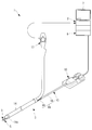
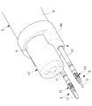
- FIG. 1 is an overall configuration diagram showing a medical system according to an embodiment of the present invention. It is a perspective view which shows a part of medical system of FIG. It is an expansion perspective view which shows an example of the medical manipulator and endoscope which are exposed to the front-end
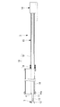
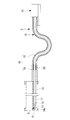
- FIG. 4B is a longitudinal sectional view showing a state in which the distal end of the medical manipulator is accommodated in the channel of the overtube by extending and bending the overtube of FIG. 4A. It is a longitudinal cross-sectional view which shows the modification of FIG.
- FIG. 5B is a longitudinal sectional view showing a state in which the distal end of the medical manipulator is accommodated in the channel of the overtube by extending and bending the overtube of FIG. 5A. It is a longitudinal cross-sectional view which shows the other modification of FIG. 4A.
- FIG. 6B is a longitudinal sectional view showing a state in which the distal end of the medical manipulator is accommodated in the channel of the overtube by extending and bending the overtube of FIG. 6A. It is a perspective view which shows the modification of the medical system of FIG.
- the medical system 1 includes an operation input unit 2 that is operated by an operator O, an overtube 3 that is inserted into a body cavity of a patient P, and the overtube 3.
- Two medical manipulators 5 respectively inserted into the two channels 4 of the tube 3, an endoscope 17 inserted into the channel 9 of the overtube 3, and a medical manipulator based on the operation of the operation input unit 2 5, a control unit 6 that controls the drive unit 10, a monitor 7, and a console 8 in which these operation input unit 2, drive unit 10, control unit 6, and monitor 7 are arranged. ing.
- the medical manipulator 5 changes the posture of the elongated flexible portion 11, the treatment portion 12 such as a grasping forceps disposed at the tip of the flexible portion 11, and the posture of the treatment portion 12. And a joint 13 to be operated.
- the drive unit 10 is connected to the proximal end of the flexible unit 11, and generates power for driving the medical manipulator 5 in response to a command from the control unit 6 based on an operation to the operation input unit 2. It is supposed to occur.
- the drive unit 10 includes a motor (not shown) that generates power, and operates the treatment unit 12 and the joint 13 via a power transmission member such as a wire by rotation of the motor.
- the overtube 3 is disposed on the distal end side and is connected to the proximal end side of the distal end portion 14 to be inserted outside the body. And a long base end portion 15 to be disposed.
- the channel 4 extends through the distal end portion 14 and the proximal end portion 15 in the longitudinal direction.
- the base end portion 15 disposed outside the body has a stretchable bending portion in which a stretchable portion (stretching portion) 16 that expands and contracts (extends) in the longitudinal direction and a bendable bending portion 18 are arranged in series.
- a portion (extension bending portion) 19 is provided.
- Reference numeral 14 a is a cap provided at the tip of the tip portion 14.
- the distal end portion 14 is provided with two channels 4 for inserting the medical manipulator 5 and a single channel 9 for inserting the endoscope.
- the proximal end portion 15 is provided with two channels 4 for inserting the medical manipulator 5.
- the expansion / contraction part 16 is comprised by the bellows, as FIG. 4A and FIG. 4B show.
- the bending portion 18 is made of, for example, a rubber tube.
- FIG. 4B when the operator O applies an external force in a direction intersecting the longitudinal direction to the bending portion 18, the bending portion 18 is bent and the expansion / contraction portion 16 extends to extend the overtube 3.
- the total length can be extended.
- the proximal end of the medical manipulator 5 is fixed to the drive unit 10 and does not move, and the entire length of the medical manipulator 5 does not change, the medical device that protrudes forward from the distal end of the overtube 3. The distal end of the manipulator 5 is drawn into the channel 4 of the overtube 3.
- the distal end portion 14 of the overtube 3 is inserted into the body cavity of the patient P and is disposed outside the body of the patient P.
- the medical manipulator 5 is inserted into the channel 4 from the proximal end of the proximal end portion 15, and the treatment portion 12 at the distal end of the medical manipulator 5 is projected forward from the distal end of the overtube 3.
- the proximal end of the medical manipulator 5 protruding backward from the proximal end of the proximal end portion 15 of the overtube 3 is connected to the drive unit 10.
- the joint 13 and the treatment unit 12 at the distal end of the medical manipulator 5 can be operated to treat the affected part.
- the tip of the medical manipulator 5 may be pulled into the channel 4.
- the movement of the tip of the overtube 3 includes an advancing / retreating movement and a bending movement.
- the bending movement may be performed by a wire (not shown) or may be performed by using a bending portion of the endoscope 17 inserted into another channel 9.
- the operator O applies an external force in a direction intersecting the longitudinal direction to the bending portion 18 of the telescopic bending portion 19 provided in the proximal end portion 15 disposed outside the body of the patient P. Then, a part of the base end portion 15 is partially curved. Thereby, since the distance between the both ends of the bending portion 18 is reduced by bending the bending portion 18 which is a straight line, the expansion / contraction portion 16 is extended so as to compensate for the decrease.
- the bending portion 18 of the base end portion 15 is bent and the expansion / contraction portion 16 is extended without moving both ends of the base end portion 15.
- the overall length of the overtube 3 can be increased, and the treatment portion 12 at the distal end of the medical manipulator 5 whose overall length does not change can be drawn into the channel 4 of the overtube 3.
- the tip of the medical manipulator 5 can be drawn into the channel 4 while the base end of the medical manipulator 5 is still connected to the drive unit 10, and the tip of the overtube 3 can be quickly moved. .
- the overtube 3 and the medical system 1 when the proximal end of the medical manipulator 5 cannot be retracted to the proximal end fixed to the drive unit 10, or the distal end is in the channel 4.
- the treatment portion 12 at the distal end of the medical manipulator 5 can be retracted into the channel 4 of the overtube 3 even when there is not enough space on the proximal end side to retract.
- the bellows is adopted as the stretchable part 16, but instead of this, a rubber tube that can be stretched in the longitudinal direction or a telescopic structure that can be nested can be adopted.
- the expansion / contraction part 16 and the bending part 18 are arranged in series as the expansion / contraction bending part 19. You may employ
- the expansion-contraction part 16 and the curved part 18 were arrange
- an inner tube 20 that covers the inner surface of the contracted bellows 16 is disposed, and one end of the inner tube 20 is connected to the bellows 16. You may fix to the end of.
- the inner tube 20 is fixed to the proximal end side of the bellows 16, but the inner tube 20 may be fixed to the distal end side of the bellows 16.
- fixing means capable of switching between a state in which the bellows 16 is fixed in a contracted state and a state in which the bellows 16 is allowed to extend when the bellows 16 needs to be stretched.
- the fixing means is provided so as to be detachable in the radial direction, constrains the bellows 16 so that it does not stretch in the attached state, and removes the bellows 16 in the radially outward state.
- a lock mechanism 21 that releases the constraint can be employed.
- the detachable lock mechanism 21 replaces with the detachable lock mechanism 21, is provided so that it can slide, and restrains the bellows 16 from extending
- a lock mechanism that releases the restraint may be employed. Further, a swing type may be adopted instead of the slide type. Also, any other lock mechanism may be adopted.
- the locking means 22 as shown in FIG. 7, a hook or the like that is disposed in the vicinity of the overtube 3 and hooks the curved portion 18 that is curved can be employed.
- tip of the medical manipulator 5 can be maintained in the state pulled in in the channel 4 of the overtube 3, and the front-end
Landscapes
- Health & Medical Sciences (AREA)
- Life Sciences & Earth Sciences (AREA)
- Surgery (AREA)
- Engineering & Computer Science (AREA)
- General Health & Medical Sciences (AREA)
- Veterinary Medicine (AREA)
- Public Health (AREA)
- Animal Behavior & Ethology (AREA)
- Nuclear Medicine, Radiotherapy & Molecular Imaging (AREA)
- Molecular Biology (AREA)
- Biomedical Technology (AREA)
- Heart & Thoracic Surgery (AREA)
- Medical Informatics (AREA)
- Biophysics (AREA)
- Radiology & Medical Imaging (AREA)
- Physics & Mathematics (AREA)
- Pathology (AREA)
- Optics & Photonics (AREA)
- Robotics (AREA)
- Ophthalmology & Optometry (AREA)
- Endoscopes (AREA)
Abstract
チャネル内に移動可能に挿入された医療用マニピュレータの基端側が拘束されている場合であっても、先端から突出している医療用マニピュレータの先端を後退させてチャネル内に引き込むことを目的として、本発明に係るオーバーチューブ(3)は、患者の体腔内に挿入される長尺の先端部(14)と、先端部(14)の基端側に接続する長尺の基端部(15)と、先端部(14)および基端部(15)を長手方向に貫通して医療用マニピュレータ(5)を挿入可能なチャネルとを備え、基端部(15)の少なくとも一部に、長手方向に伸張可能かつ長手方向に交差する方向に湾曲可能な伸張湾曲部を備える。
Description
本発明は、オーバーチューブおよび医療システムに関するものである。
体腔内に配置されて体腔内の患部を観察する内視鏡(親スコープ)に設けられたガイドチャネル内に、他の内視鏡(子スコープ)を挿入した親子内視鏡が知られている(例えば、特許文献1参照。)。
この親子内視鏡においては、子スコープによる観察を行うために子スコープの先端を親スコープの先端から突出させる必要がある。
この親子内視鏡においては、子スコープによる観察を行うために子スコープの先端を親スコープの先端から突出させる必要がある。
そして、子スコープを親スコープのガイドチャネル入口に取り付ける子スコープホルダを伸縮自在とし、親スコープの先端からの子スコープの突出量より子スコープホルダの伸縮量を大きくしている。これにより、子スコープホルダを伸張させることで、親スコープの先端から子スコープをガイドチャネル内に引き込むことができる。すなわち、特許文献1の親子内視鏡では、子スコープの基端側が拘束されていないため、親スコープに対して子スコープを後退させることで、子スコープを親スコープのガイドチャネル内に収容することができる。
しかしながら、子スコープの基端側が拘束されている場合、あるいは、子スコープの基端側に後退可能なスペースがない場合には、親スコープに対して子スコープを後退させることができないので、ガイドチャネル内に子スコープを収容するには、固定された子スコープに対して親スコープを前進させる必要があり、親スコープの視野が変動してしまうという不都合がある。
本発明は上述した事情に鑑みてなされたものであって、チャネル内に移動可能に挿入された医療用マニピュレータの基端側が拘束されている場合、あるいは、医療用マニピュレータの基端側に後退可能なスペースがない場合であっても、先端から突出している医療用マニピュレータの先端を後退させてチャネル内に引き込むことができるオーバーチューブおよび医療システムを提供することを目的としている。
本発明の一態様は、患者の体腔内に挿入される長尺の先端部と、該先端部の基端側に接続する長尺の基端部と、前記先端部および前記基端部を長手方向に貫通して医療用マニピュレータを挿入可能なチャネルとを備え、前記基端部の少なくとも一部に、前記長手方向に伸張可能かつ前記長手方向に交差する方向に湾曲可能な伸張湾曲部を備えるオーバーチューブである。
本態様によれば、オーバーチューブの長尺の先端部を患者の体腔内に挿入し、先端部の基端側に接続された長尺の基端部を患者の体外に配置して、先端部および基端部に設けられたチャネル内に挿入された医療用マニピュレータを駆動することにより、先端部の前方に突出させた医療用マニピュレータによって体腔内の組織に対して処置を行うことができる。この場合において、オーバーチューブの基端部に設けられた伸張湾曲部を長手方向に交差する方向に湾曲させながら長手方向に伸張させることで、医療用マニピュレータの基端を移動させることなく、医療用マニピュレータの先端をオーバーチューブに対して基端側に移動させ、医療用マニピュレータの先端をチャネル内に引き込むことができる。
上記態様においては、前記伸張湾曲部が、前記長手方向に伸張可能な伸張部と、該伸張部と前記長手方向に直列に配列され前記長手方向に交差する方向に湾曲可能な湾曲部とを備えていてもよい。
このようにすることで、伸張部を伸張させながら湾曲部を湾曲させることにより、マニピュレータの基端を移動させることなく、医療用マニピュレータの先端をオーバーチューブに対して基端側に移動させ、医療用マニピュレータの先端をチャネル内に引き込むことができる。
このようにすることで、伸張部を伸張させながら湾曲部を湾曲させることにより、マニピュレータの基端を移動させることなく、医療用マニピュレータの先端をオーバーチューブに対して基端側に移動させ、医療用マニピュレータの先端をチャネル内に引き込むことができる。
また、上記態様においては、前記伸張部を伸縮しないように固定した状態と伸張を許容する状態とを切替可能な固定手段を備えていてもよい。
このようにすることで、固定手段を作動させて伸張部を伸張しないように固定しておくことにより、チャネル内への医療用マニピュレータの挿入時等に、伸張部が意図せず伸張してしまう不都合の発生を未然に防止することができる。そして、伸張が必要な場合に固定手段を切り替えて伸張部を伸張可能とすることにより、マニピュレータの基端を移動させることなく、医療用マニピュレータの先端をオーバーチューブに対して基端側に移動させ、医療用マニピュレータの先端をチャネル内に引き込むことができる。
このようにすることで、固定手段を作動させて伸張部を伸張しないように固定しておくことにより、チャネル内への医療用マニピュレータの挿入時等に、伸張部が意図せず伸張してしまう不都合の発生を未然に防止することができる。そして、伸張が必要な場合に固定手段を切り替えて伸張部を伸張可能とすることにより、マニピュレータの基端を移動させることなく、医療用マニピュレータの先端をオーバーチューブに対して基端側に移動させ、医療用マニピュレータの先端をチャネル内に引き込むことができる。
また、上記態様においては、前記伸張部が蛇腹であってもよい。
このようにすることで、オーバーチューブの基端部を蛇腹の伸縮によって容易に伸縮させることができる。
このようにすることで、オーバーチューブの基端部を蛇腹の伸縮によって容易に伸縮させることができる。
また、上記態様においては、前記伸張部の内側に、収縮状態の前記伸張部の内面を覆う長さを有し、一端が前記伸張部のいずれかの端部に固定されたインナーチューブを備えていてもよい。
このようにすることで、蛇腹を収縮させた状態では、インナーチューブが蛇腹の内面を被覆するので、チャネル内に挿入される医療用マニピュレータが蛇腹の内面に引っ掛かることを防止して、スムーズに挿入することができる。
このようにすることで、蛇腹を収縮させた状態では、インナーチューブが蛇腹の内面を被覆するので、チャネル内に挿入される医療用マニピュレータが蛇腹の内面に引っ掛かることを防止して、スムーズに挿入することができる。
また、本発明の他の態様は、上記いずれかのオーバーチューブと、該オーバーチューブの前記チャネル内に挿入される医療用マニピュレータと、前記オーバーチューブの前記基端部の基端側から突出する前記医療用マニピュレータの基端部を接続して駆動する駆動部とを備える医療システムである。
本態様によれば、オーバーチューブの長尺の先端部を患者の体腔内に挿入し、先端部の基端側に接続された長尺の基端部を患者の体外に配置して、先端部および基端部に設けられたチャネル内に挿入された医療用マニピュレータの基端部を駆動部に接続し、駆動部を作動させることにより、先端部の前方に突出させた医療用マニピュレータによって体腔内の組織に対して処置を行うことができる。
この場合において、オーバーチューブの基端部に設けられた伸張湾曲部を長手方向に交差する方向に湾曲させながら長手方向に伸張させることで、医療用マニピュレータの基端部を取り付けている駆動部を長手方向に移動させなくても、医療用マニピュレータの先端をオーバーチューブに対して基端側に移動させ、医療用マニピュレータの先端をチャネル内に引き込むことができる。
上記態様においては、前記伸張湾曲部を伸張させた状態で係止可能な係止部を備えていてもよい。
このようにすることで、係止部により伸張湾曲部を伸張させた状態に係止することによって、医療用マニピュレータの先端がオーバーチューブのチャネル内に収容された状態に維持することができ、オーバーチューブを移動させる際に、医療用マニピュレータが邪魔になることを防止することができる。
このようにすることで、係止部により伸張湾曲部を伸張させた状態に係止することによって、医療用マニピュレータの先端がオーバーチューブのチャネル内に収容された状態に維持することができ、オーバーチューブを移動させる際に、医療用マニピュレータが邪魔になることを防止することができる。
本発明によれば、チャネル内に移動可能に挿入された医療用マニピュレータの基端側が拘束されている場合、あるいは、医療用マニピュレータの基端側に後退可能なスペースがない場合であっても、先端から突出している医療用マニピュレータの先端を後退させてチャネル内に引き込むことができるという効果を奏する。
以下、本発明の一実施形態に係るオーバーチューブ3および医療システム1について、図面を参照して以下に説明する。
本実施形態に係る医療システム1は、図1から図3に示されるように、操作者Oにより操作される操作入力部2と、患者Pの体腔内に挿入されるオーバーチューブ3と、該オーバーチューブ3の2つのチャネル4内にそれぞれ挿入される2つの医療用マニピュレータ5と、オーバーチューブ3のチャネル9内に挿入される内視鏡17と、操作入力部2の操作に基づいて医療用マニピュレータ5を駆動する駆動部10と、該駆動部10を制御する制御部6と、モニタ7と、これら操作入力部2、駆動部10、制御部6およびモニタ7が配置されたコンソール8とを備えている。
本実施形態に係る医療システム1は、図1から図3に示されるように、操作者Oにより操作される操作入力部2と、患者Pの体腔内に挿入されるオーバーチューブ3と、該オーバーチューブ3の2つのチャネル4内にそれぞれ挿入される2つの医療用マニピュレータ5と、オーバーチューブ3のチャネル9内に挿入される内視鏡17と、操作入力部2の操作に基づいて医療用マニピュレータ5を駆動する駆動部10と、該駆動部10を制御する制御部6と、モニタ7と、これら操作入力部2、駆動部10、制御部6およびモニタ7が配置されたコンソール8とを備えている。
医療用マニピュレータ5は、図3に示されるように、それぞれ、細長い軟性部11と、該軟性部11の先端に配置された把持鉗子のような処置部12と、該処置部12の姿勢を変化させる関節13とを備えている。
駆動部10は、図4Aに示されるように、軟性部11の基端に接続され、操作入力部2への操作に基づく制御部6からの指令に応じて医療用マニピュレータ5を駆動する動力を発生するようになっている。駆動部10は、動力を発生する図示しないモータを備え、モータの回転によってワイヤなどの動力伝達部材を介して処置部12および関節13を動作させるようになっている。
駆動部10は、図4Aに示されるように、軟性部11の基端に接続され、操作入力部2への操作に基づく制御部6からの指令に応じて医療用マニピュレータ5を駆動する動力を発生するようになっている。駆動部10は、動力を発生する図示しないモータを備え、モータの回転によってワイヤなどの動力伝達部材を介して処置部12および関節13を動作させるようになっている。
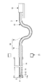
オーバーチューブ3は、図1および図4Aに示されるように、先端側に配置され患者Pの体内に挿入される長尺の先端部14と、該先端部14の基端側に接続され体外に配置される長尺の基端部15とを備えている。チャネル4は先端部14および基端部15を長手方向に貫通して設けられている。体外に配置される基端部15には、その一部に、長手方向に伸縮(伸張)する伸縮部(伸張部)16と、湾曲可能な湾曲部18とを直列に配置してなる伸縮湾曲部(伸張湾曲部)19が設けられている。符号14aは、先端部14先端に設けられるキャップである。
先端部14には、医療用マニピュレータ5を挿入するための2つのチャネル4、および内視鏡を挿入するための単一のチャネル9が設けられている。また、基端部15には、医療用マニピュレータ5を挿入するための2つのチャネル4が設けられている。
伸縮部16は、図4Aおよび図4Bに示されるように、蛇腹により構成されている。湾曲部18は、例えば、ゴムチューブにより構成されている。これにより、図4Bに示されるように、操作者Oが湾曲部18に、長手方向に交差する方向の外力を加えると、湾曲部18が湾曲するとともに伸縮部16が伸張してオーバーチューブ3の全長を延ばすことができるようになっている。
この場合において、医療用マニピュレータ5の基端は駆動部10に固定されているので移動せず、また、医療用マニピュレータ5の全長は変化しないので、オーバーチューブ3の先端から前方に突出していた医療用マニピュレータ5の先端がオーバーチューブ3のチャネル4内に引き込まれるようになっている。
このように構成された本実施形態に係るオーバーチューブ3および医療システム1の作用について以下に説明する。
本実施形態に係る医療システム1を用いて患者Pの体腔内の患部を処置するには、オーバーチューブ3の先端部14を患者Pの体腔内に挿入し、患者Pの体外に配置されている基端部15の基端からチャネル4内に医療用マニピュレータ5を挿入し、医療用マニピュレータ5の先端の処置部12をオーバーチューブ3の先端から前方に突出させる。
本実施形態に係る医療システム1を用いて患者Pの体腔内の患部を処置するには、オーバーチューブ3の先端部14を患者Pの体腔内に挿入し、患者Pの体外に配置されている基端部15の基端からチャネル4内に医療用マニピュレータ5を挿入し、医療用マニピュレータ5の先端の処置部12をオーバーチューブ3の先端から前方に突出させる。
そして、オーバーチューブ3の基端部15の基端から後方に突出している医療用マニピュレータ5の基端を駆動部10に接続する。この状態で、制御部6からの信号に基づいて駆動部10を作動させることにより、医療用マニピュレータ5の先端の関節13および処置部12を作動させて、患部の処置を行うことができる。
この場合において、オーバーチューブ3の先端の位置を変更する場合には、チャネル4内に医療用マニピュレータ5の先端を引き込む場合がある。ここで、オーバーチューブ3の先端の移動は、進退移動や湾曲移動がある。湾曲移動は,図示しないワイヤによって行ってもよいし、他のチャネル9に挿入した内視鏡17の湾曲部を利用して行ってもよい。
この場合には、操作者Oが、患者Pの体外に配置されている基端部15に備えられている伸縮湾曲部19の湾曲部18に、長手方向に交差する方向の外力を加えることにより、基端部15の一部を部分的に湾曲させる。これにより、直線だった湾曲部18が湾曲させられることによって、湾曲部18の両端の距離が減少するので、その減少分を補うように伸縮部16が伸張させられる。
すなわち、本実施形態に係るオーバーチューブ3および医療システム1によれば、基端部15の湾曲部18を湾曲させ、伸縮部16を伸張させることによって、基端部15の両端を移動させることなくオーバーチューブ3の全長を長くすることができ、全長の変化しない医療用マニピュレータ5の先端の処置部12をオーバーチューブ3のチャネル4内に引き込むことができる。
その結果、医療用マニピュレータ5の基端を駆動部10との接続したままの状態で医療用マニピュレータ5の先端をチャネル4内に引き込んで、迅速に、オーバーチューブ3の先端を移動させることができる。
このように、本実施形態に係るオーバーチューブ3および医療システム1によれば、医療用マニピュレータ5の基端が駆動部10に固定された基端側に後退できない場合や、先端をチャネル4内に引き込むために十分なスペースが基端側に存在しない場合においても、医療用マニピュレータ5の先端の処置部12をオーバーチューブ3のチャネル4内に引き込むことができるという利点がある。
なお、本実施形態においては、伸縮部16として、蛇腹を採用したが、これに代えて、長手方向に伸縮可能なゴムチューブあるいは入れ子式の伸縮可能な構造を採用してもよい。また、伸縮湾曲部19として伸縮部16と湾曲部18とを直列に配置したが、これに代えて、長手方向に伸縮可能かつ湾曲可能なゴムチューブあるいは蛇腹のような伸縮および湾曲を同時に実現し得る部材を採用してもよい。
また、本実施形態においては、オーバーチューブ3の先端部14の基端からさらに基端側に向かって順に伸縮部16と湾曲部18とを直列に配置したが、配列順序は逆でもよい。
また、本実施形態においては、オーバーチューブ3の先端部14の基端からさらに基端側に向かって順に伸縮部16と湾曲部18とを直列に配置したが、配列順序は逆でもよい。
また、伸縮部として蛇腹16を採用する場合に、図5Aおよび図5Bに示されるように、収縮した状態の蛇腹16の内面を覆うインナーチューブ20を配置し、該インナーチューブ20の一端を蛇腹16の一端に固定してもよい。図5Aおよび図5Bに示す例では、蛇腹16の基端側にインナーチューブ20を固定したが、蛇腹16の先端側にインナーチューブ20を固定してもよい。
このようにすることで、蛇腹16が収縮した状態ではインナーチューブ20によって内面が覆われるので、医療用マニピュレータ5をチャネル4内に挿入する際に、蛇腹16内面の凹凸に医療用マニピュレータ5が引っ掛かることを防止することができる。蛇腹16を伸張させる際には既に医療用マニピュレータ5のチャネル4内への挿入が完了しているので、蛇腹16を伸張させることにより蛇腹16の内面がインナーチューブ20から外れて露出しても不都合はない。
また、本実施形態においては、蛇腹16を収縮状態に固定した状態と、蛇腹16の伸張が必要な際に蛇腹16の伸張を許容する状態とを切り替えることができる固定手段を備えていてもよい。固定手段としては、図6Aおよび図6Bに示されるように、径方向に着脱可能に設けられ、取り付けた状態で蛇腹16が伸張しないように拘束し、径方向外方に取り外した状態で蛇腹16の拘束を解放するロック機構21を採用することができる。
また、着脱可能なロック機構21に代えて、スライド可能に設けられて、径方向内方に移動した状態で蛇腹16が伸張しないように拘束し、径方向外方に移動した状態で蛇腹16の拘束を解放するロック機構を採用してもよい。また、スライド式に代えて揺動式を採用してもよい。また、他の任意のロック機構を採用してもよい。
また、本実施形態においては、蛇腹16を伸張させた状態に係止する係止手段(係止部)22を備えていてもよい。係止手段22としては、図7に示されるように、オーバーチューブ3の近傍に配置され、湾曲した湾曲部18を引っ掛けるフック等を採用することができる。これにより、医療用マニピュレータ5の先端をオーバーチューブ3のチャネル4内に引き込んだ状態に維持することができ、オーバーチューブ3の先端位置を容易に変更することができる。
1 医療システム
3 オーバーチューブ
4 チャネル
5 医療用マニピュレータ
10 駆動部
14 先端部
15 基端部
16 蛇腹(伸縮部、伸張部)
18 湾曲部
19 伸縮湾曲部(伸張湾曲部)
20 インナーチューブ
21 ロック機構(固定手段)
22 係止手段(係止部)
P 患者
3 オーバーチューブ
4 チャネル
5 医療用マニピュレータ
10 駆動部
14 先端部
15 基端部
16 蛇腹(伸縮部、伸張部)
18 湾曲部
19 伸縮湾曲部(伸張湾曲部)
20 インナーチューブ
21 ロック機構(固定手段)
22 係止手段(係止部)
P 患者
Claims (7)
- 患者の体腔内に挿入される長尺の先端部と、
該先端部の基端側に接続する長尺の基端部と、
前記先端部および前記基端部を長手方向に貫通して医療用マニピュレータを挿入可能なチャネルとを備え、
前記基端部の少なくとも一部に、前記長手方向に伸張可能かつ前記長手方向に交差する方向に湾曲可能な伸張湾曲部を備えるオーバーチューブ。 - 前記伸張湾曲部が、前記長手方向に伸張可能な伸張部と、該伸張部と前記長手方向に直列に配列され前記長手方向に交差する方向に湾曲可能な湾曲部とを備える請求項1に記載のオーバーチューブ。
- 前記伸張部を伸縮しないように固定した状態と伸張を許容する状態とを切替可能な固定手段を備える請求項2に記載のオーバーチューブ。
- 前記伸張部が蛇腹である請求項2または請求項3に記載のオーバーチューブ。
- 前記伸張部の内側に、収縮状態の前記伸張部の内面を覆う長さを有し、一端が前記伸張部のいずれかの端部に固定されたインナーチューブを備える請求項4に記載のオーバーチューブ。
- 請求項1から請求項5のいずれかに記載のオーバーチューブと、
該オーバーチューブの前記チャネル内に挿入される医療用マニピュレータと、
前記オーバーチューブの前記基端部の基端側から突出する前記医療用マニピュレータの基端部を接続して駆動する駆動部とを備える医療システム。 - 前記伸張湾曲部を伸張させた状態で係止可能な係止部を備える請求項6に記載の医療システム。
Priority Applications (2)
| Application Number | Priority Date | Filing Date | Title |
|---|---|---|---|
| PCT/JP2017/009719 WO2018163403A1 (ja) | 2017-03-10 | 2017-03-10 | オーバーチューブおよび医療システム |
| US16/171,494 US20190059705A1 (en) | 2017-03-10 | 2018-10-26 | Overtube and medical system |
Applications Claiming Priority (1)
| Application Number | Priority Date | Filing Date | Title |
|---|---|---|---|
| PCT/JP2017/009719 WO2018163403A1 (ja) | 2017-03-10 | 2017-03-10 | オーバーチューブおよび医療システム |
Related Child Applications (1)
| Application Number | Title | Priority Date | Filing Date |
|---|---|---|---|
| US16/171,494 Continuation US20190059705A1 (en) | 2017-03-10 | 2018-10-26 | Overtube and medical system |
Publications (1)
| Publication Number | Publication Date |
|---|---|
| WO2018163403A1 true WO2018163403A1 (ja) | 2018-09-13 |
Family
ID=63448404
Family Applications (1)
| Application Number | Title | Priority Date | Filing Date |
|---|---|---|---|
| PCT/JP2017/009719 Ceased WO2018163403A1 (ja) | 2017-03-10 | 2017-03-10 | オーバーチューブおよび医療システム |
Country Status (2)
| Country | Link |
|---|---|
| US (1) | US20190059705A1 (ja) |
| WO (1) | WO2018163403A1 (ja) |
Families Citing this family (3)
| Publication number | Priority date | Publication date | Assignee | Title |
|---|---|---|---|---|
| KR102515467B1 (ko) * | 2020-07-13 | 2023-03-29 | 연세대학교 원주산학협력단 | 탈착형 방사형 주사 초음파 내시경을 구비한 내시경 영상 진단 장치 |
| US20230126099A1 (en) * | 2021-10-27 | 2023-04-27 | Olympus Corporation | Endoscope system, controller, and stand |
| CN114287862B (zh) * | 2021-12-30 | 2022-10-28 | 湖南省华芯医疗器械有限公司 | 一种插接装置、内窥镜及使用方法 |
Citations (3)
| Publication number | Priority date | Publication date | Assignee | Title |
|---|---|---|---|---|
| JP2011227132A (ja) * | 2010-04-15 | 2011-11-10 | Olympus Corp | ガイドチューブ装置および内視鏡システム |
| JP2012024358A (ja) * | 2010-07-23 | 2012-02-09 | Olympus Medical Systems Corp | 挿入装置 |
| JP2014014558A (ja) * | 2012-07-10 | 2014-01-30 | Fujifilm Corp | 内視鏡装置及び内視鏡システム |
-
2017
- 2017-03-10 WO PCT/JP2017/009719 patent/WO2018163403A1/ja not_active Ceased
-
2018
- 2018-10-26 US US16/171,494 patent/US20190059705A1/en not_active Abandoned
Patent Citations (3)
| Publication number | Priority date | Publication date | Assignee | Title |
|---|---|---|---|---|
| JP2011227132A (ja) * | 2010-04-15 | 2011-11-10 | Olympus Corp | ガイドチューブ装置および内視鏡システム |
| JP2012024358A (ja) * | 2010-07-23 | 2012-02-09 | Olympus Medical Systems Corp | 挿入装置 |
| JP2014014558A (ja) * | 2012-07-10 | 2014-01-30 | Fujifilm Corp | 内視鏡装置及び内視鏡システム |
Also Published As
| Publication number | Publication date |
|---|---|
| US20190059705A1 (en) | 2019-02-28 |
Similar Documents
| Publication | Publication Date | Title |
|---|---|---|
| JP5296351B2 (ja) | 内視鏡挿入装置 | |
| US5386818A (en) | Laparoscopic and endoscopic instrument guiding method and apparatus | |
| JP3370601B2 (ja) | 内視鏡用処置具の操作部 | |
| JP5273980B2 (ja) | 内視鏡用結紮具及び内視鏡結紮システム | |
| US8211114B2 (en) | Medical instrument having a medical snare | |
| JP5210465B2 (ja) | 内視鏡 | |
| JP5865500B2 (ja) | 医療用マニピュレータ | |
| JP2006026344A (ja) | 大腸内視鏡挿入用伸展脚式移動シース | |
| WO2018163403A1 (ja) | オーバーチューブおよび医療システム | |
| KR101309496B1 (ko) | 개선된 자기-추진식 내시경 장치 | |
| US11925322B2 (en) | Endoscope with extensible work channel | |
| CN106455934A (zh) | 外套管和机械手系统 | |
| JP2020508725A5 (ja) | 外科用内視鏡 | |
| JP6714713B2 (ja) | 外科用器具 | |
| JP2024501874A (ja) | 操縦可能医療機器 | |
| JP2025526678A (ja) | 一体型器具を有する医療デバイス及び関連する方法 | |
| WO2017017753A1 (ja) | 組織回収具及び組織回収システム | |
| KR101559272B1 (ko) | 내시경 처치구용 조작장치 | |
| JP6188995B1 (ja) | マニピュレータシステムとその作動方法 | |
| US20210153727A1 (en) | Medical manipulator system and access device | |
| JP2012239833A (ja) | 内視鏡用フード | |
| JPWO2019225102A1 (ja) | 先端カバー装置、及び、内視鏡 | |
| JP6058234B1 (ja) | 内視鏡 | |
| CN221786485U (zh) | 体腔封堵装置及其操作手柄 | |
| JP5989411B2 (ja) | 腹腔鏡装置 |
Legal Events
| Date | Code | Title | Description |
|---|---|---|---|
| 121 | Ep: the epo has been informed by wipo that ep was designated in this application |
Ref document number: 17900266 Country of ref document: EP Kind code of ref document: A1 |
|
| NENP | Non-entry into the national phase |
Ref country code: DE |
|
| 122 | Ep: pct application non-entry in european phase |
Ref document number: 17900266 Country of ref document: EP Kind code of ref document: A1 |
|
| NENP | Non-entry into the national phase |
Ref country code: JP |