WO2018159589A1 - 調光素子、調光部材、及び調光複層ガラス - Google Patents
調光素子、調光部材、及び調光複層ガラス Download PDFInfo
- Publication number
- WO2018159589A1 WO2018159589A1 PCT/JP2018/007182 JP2018007182W WO2018159589A1 WO 2018159589 A1 WO2018159589 A1 WO 2018159589A1 JP 2018007182 W JP2018007182 W JP 2018007182W WO 2018159589 A1 WO2018159589 A1 WO 2018159589A1
- Authority
- WO
- WIPO (PCT)
- Prior art keywords
- light control
- metal
- metal complex
- layer
- light
- Prior art date
- Legal status (The legal status is an assumption and is not a legal conclusion. Google has not performed a legal analysis and makes no representation as to the accuracy of the status listed.)
- Ceased
Links
Images







Classifications
-
- G—PHYSICS
- G02—OPTICS
- G02F—OPTICAL DEVICES OR ARRANGEMENTS FOR THE CONTROL OF LIGHT BY MODIFICATION OF THE OPTICAL PROPERTIES OF THE MEDIA OF THE ELEMENTS INVOLVED THEREIN; NON-LINEAR OPTICS; FREQUENCY-CHANGING OF LIGHT; OPTICAL LOGIC ELEMENTS; OPTICAL ANALOGUE/DIGITAL CONVERTERS
- G02F1/00—Devices or arrangements for the control of the intensity, colour, phase, polarisation or direction of light arriving from an independent light source, e.g. switching, gating or modulating; Non-linear optics
- G02F1/01—Devices or arrangements for the control of the intensity, colour, phase, polarisation or direction of light arriving from an independent light source, e.g. switching, gating or modulating; Non-linear optics for the control of the intensity, phase, polarisation or colour
- G02F1/17—Devices or arrangements for the control of the intensity, colour, phase, polarisation or direction of light arriving from an independent light source, e.g. switching, gating or modulating; Non-linear optics for the control of the intensity, phase, polarisation or colour based on variable-absorption elements not provided for in groups G02F1/015 - G02F1/169
Definitions
- the present invention relates to a light control element, a light control member, and a light control multilayer glass.
- the ratio of light and heat entering and exiting is large.
- the ratio of light and heat flowing out of the window during heating in winter is about 50% of the total heat flowing out of the building, and the ratio of light and heat flowing in from the window during cooling in summer flows into the building. It is about 70% of the total heat. Therefore, enormous energy saving effect can be obtained by appropriately controlling light and heat in and out of the window.
- the light control glass has been developed for such a purpose, and has a function of controlling inflow and outflow of light and heat.
- thermochromic light control glass glass whose light transmittance changes reversibly according to temperature
- thermochromic light control glass glass whose light transmittance is reversibly changed by atmospheric gas
- the gas chromic light control glass is expected to be a light control glass that can be manufactured at low cost because the structure is not complicated compared to the electrochromic light control glass. Therefore, many studies have been made on the material of the gaschromic light control element and the structure of the light control glass.
- Non-Patent Document 1 describes a gaschromic light control device in which a layer of a mixture in which nanopalladium particles are adhered to the surface of nickel oxyhydroxide particles is formed on a transparent substrate.
- Patent Document 1 discloses a gas chromic light control element using a light control material containing tungsten oxide (WO 3 ) and palladium particles dispersed in silicon dioxide.
- Patent Document 2 discloses a reflective light control thin film material comprising a multilayer thin film using a magnesium-zirconium alloy thin film as a light control layer.
- the reflective dimming thin film material has a structure in which a catalyst layer is formed on the surface of the dimming layer, or a structure in which a protective layer is further formed on the catalyst layer.
- the reflective light-control thin film material has a chromic characteristic that becomes a colorless and transparent state by hydrogenation near 20 ° C. at room temperature, or a chromic characteristic that becomes a mirror state by dehydrogenation near 20 ° C. at room temperature.
- Patent Document 3 discloses a method for producing an electrochromic device using Prussian blue-type metal complex particles.
- Non-Patent Document 1 the color change due to the redox reaction is not significant under normal conditions, and the color changes between black and white. However, it was not transparent and its use as a light control element was limited.
- the light control element using the metal oxide described in Patent Document 1 has low durability, and the light control element using the metal alloy described in Patent Document 2 has low weather resistance.
- the electrochromic light control glass as described in Patent Document 3 requires the light control element to have a multilayer thin film structure of about five layers, and the cost of the transparent conductive film. There is a problem that becomes very high.
- Prussian blue type metal complex is an inorganic material, and it is considered that there is no major problem with respect to weather resistance. Liquids are used, and in all cases, weather resistance may be a problem.
- An object of one embodiment of the present invention is to provide a gaschromic light control device using a metal complex that is excellent in environmental resistance.
- a dimming device comprising a dimming layer comprising a metal complex represented by the formula: and a catalyst nanoparticle that promotes a redox reaction of the metal complex,
- the light control element in which the atmospheric gas is a combination of a gas containing hydrogen and a gas containing oxygen or ozone.
- A is a cation
- M A is vanadium, chromium, manganese, iron, ruthenium, cobalt, rhodium, nickel, palladium, platinum, copper, silver, zinc, lanthanum, europium, gadolinium, lutetium, barium , strontium, and represents one or two or more metal atoms selected from the group consisting of calcium
- M B consists of vanadium, chromium, molybdenum, tungsten, manganese, iron, ruthenium, cobalt, nickel, platinum, and copper
- x is a number from 0 to 3
- y is a number from 0.3 to 1.5
- z is a number from 0 to 30
- the reduction potential of the metal complex is ⁇ 0.22 [VvsAg / AgCl] or higher, the oxidation potential is +0.62 [VvsAg / AgCl] or lower, and the atmosphere gas is a gas containing hydrogen.
- a reduction potential of the metal complex is ⁇ 0.22 [VvsAg / AgCl] or more, an oxidation potential is +0.62 [VvsAg / AgCl] or more, +2.3 [VvsAg / AgCl] or less, and the atmospheric gas is a combination of a gas containing hydrogen and a gas containing ozone.
- the metal complex, the metal atom M A and a cyano group between the metal atom M B (CN) is a crystal of a metal complex obtained by crosslinking, cationic metal atoms M C around the crystal ions and / or metal atom M D to the arrangement of those obtained by binding metal cyano complex anions, of which central metal is characterized by [1] to light control device according to any one of [5].
- the metal atom M C consists of vanadium, chromium, manganese, iron, ruthenium, cobalt, rhodium, nickel, palladium, platinum, copper, silver, zinc, lanthanum, europium, gadolinium, lutetium, barium, strontium, and calcium is one or more metal atoms selected from the group
- the metal atom M D is selected vanadium, chromium, molybdenum, tungsten, manganese, iron, ruthenium, cobalt, nickel, platinum, and from the group consisting of copper
- the metal atom M D is selected vanadium, chromium, molybdenum, tungsten, manganese, iron, ruthenium, cobalt, nickel, platinum, and from the group consisting of copper
- the metal atom M D is selected vanadium, chromium, molybdenum, tungsten, manganese, iron, ruthenium, cobalt, nickel, platinum, and
- the catalyst nanoparticle layer includes at least one selected from the group consisting of palladium, a palladium alloy, platinum, and a platinum alloy, [1] 1 to [6] Dimmer element.
- a light control member wherein a film including the light control element according to any one of [1] to [8] is formed on a transparent substrate.
- [12] having two or more glass substrates;
- a light control multilayer glass wherein a film including the light control element according to any one of [1] to [8] is formed between the two glass substrates.
- a gas chromic light control device using a metal complex having excellent environmental resistance is provided.
- FIG. 2 is an FT-IR spectrum of the light control device of Example 1.
- FIG. 2 is a graph which shows the integrated intensity
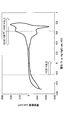
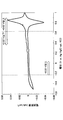
- FIG. 2 is a cyclic voltammogram of the metal complex of Example 1.
- FIG. 2 is a schematic view showing an optical device for measuring the light transmittance of the light control multilayer glass of Example 1.
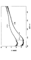
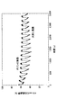
- FIG. 2 is a light transmission spectrum of the light control multilayer glass of Example 1. It is a figure which shows the relationship (cycle: 4 times) of the change of the atmosphere of the gas filling chamber of the light control multilayer glass of Example 1, and the change of the light transmittance. It is a figure which shows the relationship (cycle: 380 times) of the change of the atmosphere of the gas filling chamber of the light control multilayer glass of Example 1, and the change of light transmittance. It is a light transmission spectrum of the light control multilayer glass of Example 2.
- 4 is a light transmission spectrum of the light control multilayer glass of Example 3. It is a light transmission spectrum of the light control multilayer glass of Example 4.
- the cyclic voltammogram of the water-dispersible nickel-iron PB type complex of Example 5 is shown. It is the light transmission spectrum of the light control multilayer glass of Example 5. It is a figure which shows the relationship (cycle: 33 times) of the change of the atmosphere of the gas filling chamber of the light control multilayer glass of Example 5, and the change of the light transmittance. It is a light transmission spectrum of the light control multilayer glass of Example 6. It is a figure which shows the relationship (cycle: 14 times) with the change of the atmosphere of the gas filling chamber of the light control multilayer glass of Example 6, and the change of the light transmittance.
- the cyclic voltammogram of the water-dispersible copper-iron PB type complex of Example 7 is shown. It is the light transmission spectrum of the light control multilayer glass of Example 7. It is a figure which shows the relationship (cycle: 17 times) of the change of the atmosphere of the gas filling chamber of the light control multilayer glass of Example 7, and the change of the light transmittance.
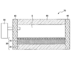
- FIG. 1 shows an example of a light control element 10 according to the present embodiment.
- This embodiment is a so-called Prussian blue-type metal complex light control device (hereinafter also referred to as a PB-type complex light control device) using a Prussian blue-type metal complex.
- the light control element 10 reversibly changes its light transmittance by an oxidation-reduction reaction with the atmospheric gas, that is, reversibly changes between a colorless (transparent) state and a colored state. Therefore, the light control device according to the present embodiment can be suitably used for light control glass that controls inflow and outflow of light and heat.
- the light control element 10 includes a light control layer (laminated body) in which the catalyst nanoparticle layer 10b including the catalyst nanoparticles 1b is attached to the surface of the metal complex layer 10a.
- the catalyst nanoparticle layer 10b functions as a catalyst for the redox reaction of the metal complex layer 10a.
- the metal complex layer 10a may be colorless (transparent) when it is in an oxidized state and colored when it is in a reduced state. Further, it may be colorless when in a reduced state and colored when in an oxidized state.
- the transmittance of light having a wavelength of 400 to 870 nm can be changed to change between a colorless (transparent) state and a colored state.
- the colorless (transparent) state and the colored state can be evaluated by measuring the transmittance of light having wavelengths of 700 nm, 420 nm, and 475 nm depending on the material.
- the atmospheric gas that causes a color change in the Prussian blue-type metal complex can be a gas containing hydrogen, oxygen, ozone, or the like.
- a combination of at least two gases that is, a gas that promotes reduction of the metal complex and a gas that promotes oxidation of the metal complex can be used.
- a gas containing hydrogen as a reducing gas and a gas containing oxygen as an oxidizing gas can be used in combination.
- a combination of a gas containing hydrogen as the reducing gas and a gas containing ozone as the oxidizing gas can be used.
- the oxidizing gas a gas containing oxygen and ozone can be used, and air can also be used.
- the reduction potential of the metal complex layer 10a is present at ⁇ 0.22 [VvsAg / AgCl] or higher and the oxidation potential is present at +2.3 [VvsAg / AgCl] or lower.
- the oxidation potential is below +0.62 [VvsAg / AgCl]
- a gas having a lower oxidizing power can be used as the oxidizing gas of the atmospheric gas as will be described later.
- the potential [VvsAg / AgCl] is a standard potential measured with reference to a silver-silver chloride electrode.
- the reduction peak potential and oxidation peak potential of a given metal complex can be measured by cyclic voltammetry (CV).
- the light control device 10 including a metal complex having a reduction potential of ⁇ 0.22 [VvsAg / AgCl] or more is exposed to an atmosphere containing hydrogen, the catalyst nanoparticle layer 10b attached to the surface of the metal complex layer 10a. Due to the catalytic action, the metal complex layer 10a is reduced, the light transmittance is changed in the wavelength range of 400 to 870 nm, and the color of the metal complex layer 10a is changed.
- the metal complex layer 10a reacts with hydrogen as follows by the catalytic action of the catalyst nanoparticle layer 10b attached to the surface thereof.
- E is the redox potential. It can be said that the atmosphere containing hydrogen has a reducing ability of ⁇ 0.22 [VvsAg / AgCl]. Therefore, when the reduction potential of the metal complex is ⁇ 0.22 [VvsAg / AgCl] or higher, it can react well with hydrogen. Therefore, a color change can be caused in the light control element 10 by using a gas containing hydrogen as the reducing gas.
- oxygen has an oxidation ability of +0.62 [VvsAg / AgCl]. Therefore, when the oxidation potential of the metal complex is +0.62 [VvsAg / AgCl] or less, it can react well with oxygen. Therefore, by using a gas containing oxygen as the oxidizing gas, it is possible to cause a color change in the light control element 10.
- the light control device 10 when the light control device 10 is exposed to an atmosphere containing ozone, the following reaction occurs due to the ozone and the light control device 10.
- ozone has a stronger oxidation ability than oxygen of +2.3 [VvsAg / AgCl]. Therefore, even if the oxidation potential of the metal complex is +0.62 [VvsAg / AgCl] or higher, it can react well with ozone as long as it is +2.3 [VvsAg / AgCl] or lower. Therefore, a color change can be caused in the light control element 10 by using a gas containing ozone as the oxidizing gas.
- the light control element 10 can be produced by coating the metal complex layer 10a and the catalyst nanoparticle layer 10b with a spin coater. Moreover, in application
- the metal complex and the catalyst nanoparticles are each dispersed in a solvent to prepare a dispersion, and the dispersion is sequentially coated.
- a solvent used for preparation of a dispersion liquid Water, methanol, ethanol, an organic solvent, etc. are mentioned. Of these, water is preferred.
- PB type complex ultrafine particles of a Prussian blue type metal complex (hereinafter sometimes abbreviated as “PB type complex”) are contained in the metal complex layer 10a.
- PB-type complex is a crystal between the metal atom M A and the metal atom M B cyano group (CN) is crosslinked.
- the PB type complex includes Prussian blue (hereinafter sometimes abbreviated as “PB”) and analogs having the same structure as PB.
- the basic composition formula is A x M A [M B ( CN) 6] y ⁇ zH 2 O ... (1)
- A is a cation
- M A, M B are each metal atom.
- a part of the cyano group (CN) may be substituted with a hydroxyl group, an amino group, a nitro group, a nitroso group, water or the like.
- the metal atom M A is vanadium, chromium, manganese, iron, ruthenium, cobalt, rhodium, nickel, palladium, platinum, copper, silver, zinc, lanthanum, europium, gadolinium, lutetium, barium, strontium, And one or more metals selected from the group consisting of calcium.
- Iron as the metal atom M A is cobalt, nickel, vanadium, copper, manganese, or zinc are preferable, iron, copper, or nickel is more preferable.
- a combination of two kinds of metal to the metal atom M A is a combination of iron and nickel, a combination of a combination of iron and copper, or nickel and copper weight, more combinations of iron and nickel preferable.
- the metal atom M B is vanadium, chromium, molybdenum, tungsten, and manganese, iron, ruthenium, cobalt, nickel, platinum, and at one or two or more metal atoms selected from the group consisting of copper .
- iron as the metal atom M B, chromium, or cobalt is preferable, iron is particularly preferred.
- the metal atom M B, a combination of iron and chromium, the combination of iron and cobalt, or a combination of chromium and cobalt are preferable, a combination of iron and chromium is preferable.
- the cation A is not necessarily contained.
- the cation A include potassium, sodium, cesium, rubidium, hydrogen, ammonia, and the like, but are not limited thereto.
- metal ions, organic molecules, other metal complexes, etc. may be adsorbed to improve optical response, catalytic activity, dispersibility, adsorptivity to the substrate, etc.
- the main structure of the changing part may be the above composition formula.
- x is a number from 0 to 3, and preferably a number from 0 to 1.
- y is a number from 0.3 to 1.5, and is preferably a number from 0.5 to 1.
- z is a number from 0 to 30, and is preferably a number from 5 to 15.
- Metal atom M C are vanadium, chromium, manganese, iron, ruthenium, cobalt, rhodium, nickel, palladium, platinum, copper, silver, zinc, lanthanum, europium, gadolinium, lutetium, barium, strontium, and from the group consisting of calcium It may be one or more metal atoms selected.
- the metal atom M D is vanadium, chromium, molybdenum, tungsten, manganese, iron, ruthenium, cobalt, nickel, platinum, and may be one or two or more metal atoms selected from the group consisting of copper.
- the method for manufacturing the light control layer (light control device) containing the Prussian blue-type metal complex as long as a light control layer (light control device) capable of causing an oxidation-reduction reaction can be manufactured.
- Examples thereof include a method of preparing a dispersion and applying the dispersion on a substrate, a method of forming a thin film by electrolytic deposition, and the like.
- the coating method is not limited to the above-described method, and the production method, the shape of the metal complex, the dispersion state, etc. are not limited as long as the PB-type complex particles can be dispersed in a solvent.
- the particle size of the PB-type complex is preferably 500 nm or less, more preferably 200 nm or less in order to uniformly disperse in the solvent. Although there is no particular lower limit on the average particle diameter, it is practical that the average particle diameter is 3 nm or more.
- the particle size in this specification is the median diameter of the particle size distribution obtained by the dynamic light scattering method (photon correlation method).
- the modifying molecule for improving the dispersibility may be adsorbed on the surface of the metal complex particle.
- a compound having an amino group coexists with the metal complex in the metal complex layer 10a.
- the compound having an amino group may be in an ionic state.
- an organic solvent or an alcohol such as butanol it is desirable to use a compound having an amino group, particularly an amino group and an alkyl group (preferably having 3 to 100 carbon atoms, more preferably 3 to 30 carbon atoms). More preferably, it is a compound having both of 3 to 16 carbon atoms.
- oleylamine, stearylamine, propylamine, hexylamine and the like are desirable, and oleylamine, hexylamine and propylamine are particularly desirable.
- the concentration of the ultrafine particles in the dispersion is not particularly limited, but it is necessary to adjust the concentration to an appropriate concentration by a coating method in consideration of good coating and film forming properties.
- the content is preferably 1% by mass or more and 50% by mass or less, and when the spray method is used, the content is preferably 0.1% by mass or more and 15% by mass or less.
- the material constituting the catalyst nanoparticle 1b is not particularly limited as long as it functions as a catalyst for the redox reaction of the PB-type complex to be used. Examples thereof include palladium, palladium alloy, platinum, platinum alloy, and the like. May be.
- the average particle diameter of the catalyst nanoparticles 1b is preferably 1 nm or more and 100 nm or less, and more preferably 2 nm or more and 30 nm or less.
- the catalyst nanoparticles 1b preferably have a protective layer formed on the surface thereof.
- the compound constituting the protective layer include water-soluble polymers, compounds having amino groups, and thiol groups.
- the method for synthesizing the catalyst nanoparticle 1b is not particularly limited, and examples thereof include a chemical reduction method and a solution method (for example, SynthesisSynof monodisperse Au, Pt, Pd, Ru and Ir nanoparticles in ethylene glycol, Bonet, F; Delmas , V; Grugeon, S; Herrera Urbina, R; Silvert, PY et al. (1999), Nanostructured Materials vol. 11 (8) p.
- a chemical reduction method and a solution method for example, SynthesisSynof monodisperse Au, Pt, Pd, Ru and Ir nanoparticles in ethylene glycol, Bonet, F; Delmas , V; Grugeon, S; Herrera Urbina, R; Silvert, PY et al. (1999), Nanostructured Materials vol. 11 (8) p.
- nano platinum particles can be synthesized.
- the average particle size of the nano platinum particles can be measured using a particle size distribution analyzer Photo ELSZ-1000 (manufactured by Otsuka Electronics Co., Ltd.). By the synthesis described above, the average particle size of the nanoplatinum particles can be 1.5 nm, the particle size distribution can be very narrow, and the particle size can be nearly uniform.
- Platinum nanoparticles include, for example, in a reaction vessel at room temperature, a toluene organic solution of a metal compound containing platinum as a main component, a toluene solution of dodecylamine as a material constituting a protective layer, and hydrogenation Nano platinum particles can be synthesized by reacting a sodium boron reducing agent (NaBH 4 ).
- NaBH 4 sodium boron reducing agent
- the method for applying the catalyst nanoplatinum particles 1b on the metal complex layer 10a is not particularly limited. For example, 1 wt% of the catalyst nanoplatinum particles 1b in water or toluene solvent is dropped on the surface of the dried metal complex layer 10a. Uniformly dispersed catalyst nanoplatinum particles 1b can be formed on the surface of the metal complex layer 10a by spin coating. Examples of other methods for applying the catalyst nanoplatinum particles 1b include a spray coating method in which the catalyst nanoplatinum particles 1b are sprayed onto the surface of the dried metal complex layer 10a.
- the light control element 10 formed by adhering the catalyst nanoplatinum particle layer 10b including the catalyst nanoplatinum particles 1b to the surface of the metal complex layer 10a to form the light control layer is exposed to an atmosphere containing hydrogen, the light control layer
- the color changes to colorless. Specifically, when Prussian blue is used as the metal complex, the color changes from blue to colorless.
- Prussian blue is used as the metal complex
- a nickel-iron PB type complex is used as the metal complex, the color changes from yellow to colorless, and when a copper-iron PB type complex is used, the color changes from brown to colorless.
- the light control member 30 is shown as an example of this embodiment.
- the light control member 30 includes a glass base material 20 and a light control element 10 formed on the glass base material 20.
- the film thickness of the light control element 10 (in the illustrated example, the sum of the film thickness of the metal complex layer 10a and the film thickness of the catalyst nanoparticle layer 10b) is preferably 10 nm or more and 2 ⁇ m or less, and 50 nm or more and 1 ⁇ m or less. More preferably.
- the film thickness of the light control element 10 is 10 nm or more and 2 ⁇ m or less, the color change of the light control element 10 can be easily recognized.
- the thickness of the catalyst nanoparticle layer 10b is preferably 2 nm or more and 100 nm or less, More preferably, it is 5 nm or more and 70 nm or less.
- the film of the light control element 10 can be formed by a wet coating method. Thereby, the film
- the wet coating method is not particularly limited, and examples thereof include a spin coating method, a spray coating method, a dip coating method, and a drop coating method.
- the material constituting the substrate 20 is not particularly limited as long as it transmits visible light, and examples thereof include glass substrates, for example, oxides such as quartz, sapphire, and lithium niobate. Instead of a glass substrate, a transparent substrate such as a plastic substrate may be used.
- the material constituting the plastic substrate is not particularly limited as long as it transmits visible light, and examples thereof include polyethylene terephthalate (PET) and acrylic resin. Cellophane tape or the like may be used as the plastic substrate. Although it does not specifically limit as a shape of a base material, A plate shape, a sheet form, etc. are mentioned.
- the above-described form has a structure in which a layer (metal complex layer) 10a containing a PB-type complex and a layer 10b containing catalyst particles are laminated on a substrate. It is not limited to a laminated structure.
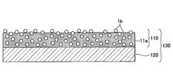
- a structure in which a PB complex and a catalyst are mixed can be used. That is, the light control device 110 including a light control layer in which the catalyst nanoparticles 11b are dispersed in the metal complex 11a can be obtained. In this case, as shown in FIG. 4, a part of the catalyst nanoparticles 11b may be exposed on the surface of the light control layer.
- Such a light control layer can be prepared by preparing a dispersion liquid containing the metal complex 11a and the catalyst nanoparticles 11b and forming the light control member 130 on the substrate 120 by the wet coating method as described above. it can.
- the film thickness of the light control element 110 is preferably 10 nm or more and 2 ⁇ m or less, and more preferably 50 nm or more and 1 ⁇ m or less.
- the light control device does not need to introduce current from the outside.
- a greater degree of structural freedom is created compared to electrochromic devices.
- the present embodiment is not limited to the illustrated one.
- grains on it are mentioned.
- the base materials (substrates) 20 and 120 have a flat plate shape, but the base material may have another shape.
- a PB-type complex and a catalyst are appropriately provided on a spherical structure, and a certain space is sealed on the upper part and a gas for controlling color change can be introduced into the space, a color can be obtained. Changes occur and can function as a gaschromic dimmer.
- FIG. 3 an example of the light control multilayer glass 70 of this embodiment is shown.
- the light control element 10 is formed between the two glass substrates 20 and 60, and the opening is sealed by the seal member 40.
- Argon gas is sealed in the gas filling chamber S in advance, and hydrogen, oxygen, or air can be supplied and exhausted by the atmosphere controller 50.
- the atmosphere controller 50 can electrolyze water, supply hydrogen or oxygen to the gas filling chamber S, and exhaust the hydrogen or oxygen from the gas filling chamber S using a vacuum pump.
- the light control element 10 When hydrogen or a gas containing hydrogen is supplied to the gas filling chamber S, the light control element 10 is reduced and the color changes. Further, when oxygen or a gas containing oxygen such as air is supplied to the gas filling chamber S, the light control element 10 is oxidized and returns to its original state.
- the light control element 10 can be reversibly controlled between the reduced state and the oxidized state. Further, when the supply / exhaust by the atmosphere controller 50 is interrupted, the reduced state or the oxidized state can be maintained. Thereby, the light control multilayer glass which can be light-controlled by a gas chromic system is obtained.
- the use of dimmable double-glazed glass in homes is progressing, and the use of double-glazed glass is becoming mainstream in newly built houses.
- the internal space can be used as the gas filling chamber S for switching.
- PB nanoparticles and a dispersion thereof were prepared by a method similar to the method described in Patent Document 3. Specifically, it is as follows.
- Preparation Example 2 Synthesis of water-dispersible nickel-iron PB complex nanoparticles>
- water-dispersible nickel-iron PB complex nanoparticles and a dispersion thereof were prepared by changing the iron salt to a nickel salt. Specifically, it is as follows.
- a dispersion (A2) was obtained.
- Preparation Example 3 Synthesis of water-dispersible copper-iron PB-type complex nanoparticles>
- water-dispersible copper-iron PB complex nanoparticles and a dispersion thereof were prepared by changing the iron salt to a copper salt. Specifically, it is as follows.
- a solution prepared by dissolving 1.98 g (6 mmol) of potassium ferricyanide in water and a solution prepared by dissolving 1.53 g (9 mmol) of hydrate in copper chloride in water were mixed together and stirred for 5 minutes.
- the precipitated brown copper-iron PB complex nanoparticle precipitates were removed by centrifugation, washed with water three times, then with methanol once, and dried under reduced pressure.
- the yield was 2.5 g, and the yield was almost 100% as Cu 3 [Fe (CN) 6 ] 2.10H 2 O.
- the obtained solution was mixed with 200 ml of water with a separatory funnel, and the upper toluene layer was collected.
- Upper layer toluene and 400 ml ethanol were mixed and stored in a freezer at ⁇ 18 ° C. for 24 hours, whereby nano platinum particles having organic solvent dispersibility were precipitated.
- the nano platinum particles were dispersed in toluene to obtain a 0.2 wt% solution.
- the average particle size of the nano platinum particles was measured using a particle size distribution analyzer (Photo ELSZ-1000, manufactured by Otsuka Electronics Co., Ltd.), it was 2.6 nm.
- ⁇ Preparation Example 5 Synthesis of ethylene glycol dispersible catalyst nano-platinum particles> After mixing 50 mg of platinum (IV) chloride (H 2 PtCl 6 ), 10 ml of water, 20 mg of polyvinylpyrrolidone (PVP) and 40 ml of ethylene glycol solution with stirring, the mixture was reacted at 150 ° C. for 2 hours to disperse ethylene glycol. A dispersion (B2) of nano platinum particles having the property was obtained. At this time, the liquid before the reaction was light yellow, but when nano platinum particles were generated, the liquid changed to dark brown. It was 1.5 nm when the average particle diameter of the nano platinum particle was measured.
- platinum (IV) chloride H 2 PtCl 6
- PVP polyvinylpyrrolidone
- PB nanoparticle dispersion liquid (A1) concentration 9 wt%) prepared in Preparation Example 1 and 5.0 ml of the nanoplatinum particle dispersion liquid (B2) of Preparation Example 5 were stirred for 2 hours to obtain a mixed liquid (C1).
- A1 concentration 9 wt% prepared in Preparation Example 1
- B2 nanoplatinum particle dispersion liquid
- C1 mixed liquid
- ⁇ Preparation Example 7 Preparation of mixed liquid of PB type complex and ethylene glycol dispersible catalyst nano platinum particles> 5.0 ml of the PB nanoparticle dispersion liquid (A1) prepared in Preparation Example 1, 1 ml of the dispersion liquid (B2) of Nanoplatinum particles of Preparation Example 5, and potassium bis (trifluoromethanesulfonyl) imide (K—) as an electrolyte (TFSI) 0.15 g was stirred for 2 hours to obtain a mixed solution (C2).
- PB nanoparticle metal complex layer By spin coating the PB nanoparticle dispersion liquid (A1) (concentration 9 wt%) prepared in Preparation Example 1 on a glass substrate (length 3.0 cm, width 3.0 cm, thickness 1.1 mm), a metal was obtained. A complex layer (L1) was produced. Specifically, a glass substrate was placed on a spin coater, 0.1 ml of the dispersion liquid (A1) was dropped, and spin coating was performed for 10 seconds by rotation at 1500 rpm, and subsequently for 10 seconds by rotation at 2000 rpm. This was allowed to stand for 30 minutes in the atmosphere of about 25 ° C., and a light control layer containing PB nanoparticles was produced. When the film thickness was measured using a stylus step meter (manufactured by KLA-Tencor Corporation, stylus step meter: ⁇ -STEP (trade name)), it was about 200 nm.
- stylus step meter manufactured by KLA-Tencor Corporation, stylus step meter: ⁇ -
- Nickel-iron PB type complex layer drop coat film formation The nickel-iron PB complex nanoparticle dispersion liquid (A2) (concentration: 8 wt%) prepared in Preparation Example 2 was used. Specifically, a glass substrate (length: 3.0 cm, width: 3.0 cm, thickness: 1.1 mm) is set, 30 ⁇ l of dispersion liquid 2 is dropped, and dispersion liquid 2 is gradually dried on the substrate surface. This was allowed to stand in the atmosphere at about 25 ° C. for 120 minutes to prepare a metal complex layer (L2) containing nickel-iron PB type complex nanoparticles. When the film thickness was measured in the same manner as in Production Example 1, it was about 350 nm.
- ⁇ Production Example 3 Spin coat film formation of copper-iron PB type complex layer> Film formation was performed using the copper-iron PB complex nanoparticle dispersion liquid (A3) (concentration 5 wt%) prepared in Preparation Example 3. Specifically, a glass substrate was placed on a spin coater, 0.2 ml of the dispersion liquid (A3) was dropped, and spin coating was performed at 500 rpm for 10 seconds and at 1000 rpm for 10 seconds. This was allowed to stand for 30 minutes in the atmosphere at about 25 ° C. to produce a metal complex layer (L3) containing copper-iron PB complex nanoparticles. When the film thickness was measured in the same manner as in Production Example 1, it was about 400 nm.
- Example 1 ⁇ Production of light control member>
- the catalyst nanoparticle layer (10b in FIG. 1) is applied.
- the metal complex layer (L1) is placed on the spin coater so that the PB nanoparticles are on top, 0.2 ml of the dispersion liquid (B1) of Preparation Example 4 is dropped, and the rotation is performed at 1000 rpm. Spin coating was performed for 10 seconds, and further at 1500 rpm for 5 seconds.
- the medium was left to stand in an atmosphere of about 25 ° C. for 30 minutes, and the medium was removed by drying. Thereby, the light control member containing a light control element and a board
- substrate was about 210 nm.
- FIG. 5 shows an FT-IR spectrum of the light control element in the light control member of Example 1 obtained as described above. It can be seen that an absorption peak (2078 cm ⁇ 1 ) due to Prussian blue is observed.
- the light control member of Example 1 was a blue uniform film.
- the FT-IR spectrum of the light control device was measured using an FT-IR Fourier transform near-infrared / middle infrared / far-infrared spectrometer (Frontier (trademark) manufactured by PerkinElmer Japan).
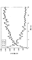
- FIG. 6 shows the integrated intensity of the X-ray photoelectron spectrum around the Fe 2p and Pt 4f of the light control device of Example 1 versus the depth of the thin film.
- the X-ray photoelectron spectrum of the light control element was measured using an X-ray photoelectron spectrometer (Theta Probe Angle-Resolved Spectrometer system, manufactured by Thermo Fisher Scientific). From FIG. 5, it can be seen that the presence of platinum nanoparticles on the surface of the light control device in Example 1 was confirmed.
- PB-type complex nanoparticle dispersion liquid (A1) concentration 9 wt%) prepared in Preparation Example 1
- 100 ⁇ l was spin-coated on the ITO film of a 3 cm ⁇ 3 cm ITO film-coated glass substrate, and a metal having a thickness of 200 nm
- a complex layer (PB nanoparticle light control layer) was formed.
- the formed metal complex layer (PB nanoparticle light control layer) is the working electrode, the Ag / AgCl electrode is the reference electrode, and the tripolar cell with the platinum wire as the counter electrode is 0.1 M potassium bis (trifluoromethanesulfonyl). Cyclic voltammetry (CV) was carried out in a propylene carbonate solution using imide (K + TFSI ⁇ ) as an electrolyte.
- the water dispersible PB nanoparticle light control layer is insoluble in propylene carbonate.
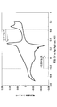
- FIG. 7 shows a cyclic voltammogram of the metal complex layer (PB nanoparticle light control layer) (sweep speed: 1 mV / s).
- the waveform is a surface adsorption wave, which suggests that the metal complex layer is stably present in the propylene carbonate solution.
- the oxidation peak potential exists at least at +0.1 [VvsAg / AgCl] and +0.3 [VvsAg / AgCl].
- reduction peak potentials exist at least at ⁇ 0.05 [VvsAg / AgCl] and +0.28 [VvsAg / AgCl]. Therefore, the above metal complex has at least two redox pairs.
- the reduction potential is ⁇ 0.22 [VvsAg / AgCl] or higher and the oxidation potential is +0.62 [VvsAg / AgCl] or lower. It was found to exist.
- a light control multilayer glass as described above with reference to FIG. 3 was prepared by combining the light control member and the glass substrate, and the light transmittance of the light control multilayer glass was measured.
- an optical device FIG. 8 provided with a light source 80 and a spectrophotometer 90 was used.
- the light control member 30 of the light control multilayer glass 70 is disposed between the light source 80 and the spectrophotometer 90 so that each surface thereof faces the glass substrate 60. Then, the opening was sealed with the sealing member 40, and the light transmittance of the light control multilayer glass was measured.
- an atmosphere controller 50 was installed to supply and exhaust gas to the gas filling chamber S. Further, as the glass substrate 20, a silica glass substrate was used. As the spectrophotometer 90, USB4000 (manufactured by Ocean optics) was used.
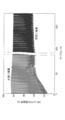
- FIG. 9 shows a light transmission spectrum of the light control multilayer glass of Example 1.
- the light transmission spectrum in the oxidized state and the reduced state is obtained by supplying an atmosphere (hereinafter, referred to as a hydrogen atmosphere) having air and hydrogen contents of 100% to the gas filling chamber S for 1 minute at room temperature. Measured at room temperature.
- a hydrogen atmosphere an atmosphere having air and hydrogen contents of 100%
- the light control multilayer glass of Example 1 is greatly changed in transmittance of light having a wavelength of 700 nm in the oxidized state and the reduced state (transmittance change amount 76.6%). It can be seen that it has gaschromic properties.
- the supply of the hydrogen atmosphere was stopped for 30 seconds.
- the supply control of the hydrogen atmosphere with this as one cycle was repeated four times, and the transmittance of light having a wavelength of 700 nm was measured every second during that period.
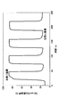
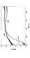
- FIG. 10A shows the relationship between the change in the atmosphere of the gas filling chamber S and the change in light transmittance.
- FIG. 10A shows that in the first supply control of the hydrogen atmosphere, the transmittance of light having a wavelength of 700 nm changes from 12.0% to 88.6% by the supply of hydrogen. In the second to fourth hydrogen atmosphere supply control, the transmittance of light having a wavelength of 700 nm is changed from 86.1% to 15.9% by stopping the hydrogen supply and allowing air to flow in. I understand that
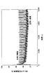
- FIG. 10B shows the results of a long-term evaluation experiment. After supplying the hydrogen atmosphere to the gas filling chamber S for 60 seconds, the cycle of stopping the supply of the hydrogen atmosphere for 120 seconds was repeated. In the 380th cycle, the change in transmittance changed from 76.6% to 41.2% by stopping the supply of hydrogen atmosphere.
- Example 2 ⁇ Production of light control member>
- the metal complex layer (L1) prepared in Preparation Example 1 was baked on a hot plate at 150 ° C. for 30 minutes to remove moisture.
- a layer of the dispersion liquid (B2) of nanoplatinum particles obtained in Preparation Example 5 was prepared by a spin coating method to obtain a light control element. Specifically, the metal complex layer (L1) was placed on the spin coater so that the PB nanoparticles were on top, 0.2 ml of the dispersion liquid (B2) of Preparation Example 5 was dropped, and the spin coating was performed at 500 rpm. Rotation was performed for 10 seconds, followed by rotation at 1500 rpm for 5 seconds.
- substrate was produced.
- substrate was about 200 nm.
- a light control multilayer glass was produced in the same manner as in Example 1, and the light transmission characteristics were measured by the same method using the same optical apparatus as in Example 1.
- FIG. 11 shows a light transmission spectrum of the light control multilayer glass of Example 2. After the hydrogen atmosphere was supplied to the gas filling chamber S at room temperature for 1 minute, the light transmittance was measured. As a result, the transmittance is greatly changed (transmittance variation of 72.0% at a wavelength of 700 nm), and it can be seen that the light control multilayer glass of Example 2 has high performance gaschromic characteristics.
- Example 3 ⁇ Production of light control member>
- the liquid mixture (C1) obtained in Preparation Example 6 was applied onto a substrate by a spin coating method to produce a light control member including a light control element using a PB type complex.
- the method of coating and the measurement of the film thickness were performed in the same manner as the method for manufacturing the metal complex layer (L1) in Preparation Example 2.
- the film thickness of the light control element formed on the substrate was about 180 nm.
- FIG. 4 schematically shows an example of the light control member of Example 3.
- the catalyst nanoparticles 11b of this example are dispersed in the metal complex 11a and form a light control element (light control layer) 110.
- the light control member 130 includes a base material 120 and a light control element 110.
- a light control multilayer glass was produced in the same manner as in Example 1, and the light transmission characteristics were measured by the same method using the same optical apparatus as in Example 1.
- FIG. 12 shows the light transmission spectrum of the light control multilayer glass of Example 3. After supplying a hydrogen atmosphere to the gas filling chamber S at room temperature for 30 minutes, the light transmittance was measured. As a result, since the transmittance is greatly changed (the transmittance change amount of the wavelength is 700 nm, 53.9%), it can be seen that the light control multilayer glass of Example 3 has high performance gaschromic characteristics.
- Example 4 ⁇ Production of light control member>
- the liquid mixture (C2) obtained in Preparation Example 7 was applied onto a substrate by a spin coating method to produce a light control member including a light control element.
- the method of coating and the measurement of the film thickness are the same as the production of the metal complex layer (L1) in Production Example 2.
- the film thickness of the light control element formed on the substrate was about 250 nm.
- a light control multilayer glass was produced in the same manner as in Example 1, and the light transmission characteristics were measured by the same method using the same optical apparatus as in Example 1.
- FIG. 13 shows a light transmission spectrum of the light control multilayer glass of Example 4. After supplying a hydrogen atmosphere to the gas filling chamber S at room temperature for 3 minutes, the light transmittance was measured. As a result, the transmittance is greatly changed (transmittance variation 82.1% at a wavelength of 700 nm), and it can be seen that the light control multilayer glass of Example 4 has high-performance gaschromic characteristics.
- Example 5 ⁇ Production of light control member> A catalyst nanoparticle layer is formed by applying the dispersion liquid (B1) of Preparation Example 4 by spin coating on the nickel-iron PB type complex layer (L2) prepared in Preparation Example 2. A PB type complex light control member including the complex light control element was produced. The coating method and the film thickness were measured in the same manner as in Example 1. The film thickness of the light control element formed on the substrate was about 400 nm.
- PB type complex nickel-iron PB type complex
- electrochemical characteristics of the PB type complex (nickel-iron PB type complex) used in this example were measured. The measurement was performed in the same manner as the measurement of the electrochemical characteristics of the PB type complex (Prussian blue) in Example 1, except that the PB type complex nanoparticle dispersion liquid (A2) prepared in Preparation Example 2 was used.
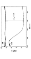
- FIG. 14 shows a cyclic voltammogram of the obtained metal complex layer (nickel-iron PB type complex layer) (sweep speed: 1 mV / s).
- the waveform is a surface adsorption wave, which suggests that the metal complex layer is stably present in the propylene carbonate solution.
- the oxidation peak electric potential exists in +0.62 [VvsAg / AgCl] and +0.78 [VvsAg / AgCl].
- reduction peak potentials exist at +0.59 [VvsAg / AgCl] and +0.72 [VvsAg / AgCl]. Therefore, the metal complex obtained in Preparation Example 2 has at least two redox pairs.
- Example 5 when a combination of a gas containing hydrogen and a gas containing oxygen or air is used as the atmospheric gas, the first oxidation-reduction pair (+0.62 V, +0.59 [VvsAg / AgCl]) By using the light control member, the dimming member exhibits gas chromic characteristics.
- the first oxidation-reduction pair (+0.62 V, +0.59 [VvsAg / AgCl]) and / or the second The redox couple of (+0.78 V, +0.72 [VvsAg / AgCl]) can be used. Since ozone has a higher oxidation-reduction potential than oxygen and has a stronger oxidation ability than air, a larger color change can be obtained when ozone is used.
- a light control multilayer glass was produced in the same manner as in Example 1, and the light transmission characteristics were measured by the same method using the same optical apparatus as in Example 1.
- FIG. 15 shows a light transmission spectrum of the light control multilayer glass of Example 5. After the hydrogen atmosphere was supplied to the gas filling chamber S from the air state at room temperature for 3 minutes, the light transmittance was measured. As a result, the transmittance is greatly changed (transmittance variation of 28.7% at a wavelength of 400 nm), and it can be seen that the light control multilayer glass of Example 5 has excellent gaschromic properties.
- the supply of the hydrogen atmosphere was stopped for 120 seconds.
- the supply control of the hydrogen atmosphere with this as one cycle was repeated 33 times, and the transmittance of light having a wavelength of 400 nm was measured every second during that time.
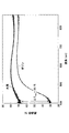
- FIG. 16 shows the relationship between the change in the atmosphere of the gas filling chamber S and the change in light transmittance.
- FIG. 16 shows that in the first hydrogen atmosphere supply control, the transmittance of light having a wavelength of 400 nm is changed from 22.0% to 57.3% by the supply of hydrogen.
- the second to 33rd hydrogen atmosphere supply control when the hydrogen supply is stopped and air is introduced, the transmittance of light having a wavelength of 400 nm is changed from 53.1% to 27.8%. I understand that.
- Example 6 ⁇ Production of light control member> In the same manner as in Example 5, a light control member including a light control element using a PB type complex was produced.
- FIG. 17 the light transmission spectrum of the light control multilayer glass of Example 6 is shown.
- a state in which the gas filling chamber S was filled with ozone was constructed, and then a hydrogen atmosphere was supplied for 1 minute at room temperature, and then the light transmittance was measured.
- An ozone generator (Soec V350, manufactured by Marco Co.) was used for generating ozone. Further, ozone was supplied under conditions of an ozone output of 35 mg / h and an air volume of 5 L / min.
- Example 5 As a result of the above measurement, it was found that the transmittance changed more compared with Example 5 (a transmittance change amount of 38.1% at a wavelength of 400 nm). That is, it turned out that the light control multilayer glass of Example 6 which uses hydrogen and ozone as atmospheric gas has a further favorable gas chromic characteristic.
- FIG. 18 shows the relationship between the change in atmosphere in the gas filling chamber S (ozone and hydrogen) and the change in light transmittance. From FIG. 18, it can be seen that in the air supply control of the hydrogen atmosphere and the ozone atmosphere, the transmittance of light having a wavelength of 400 nm is changed from 68.0% to 25.1% by the supply of ozone.
- ozone instead of air (oxygen)
- the time required for switching the light transmittance of the light control multilayer glass is significantly reduced, and the amount of change in the light transmittance of the light control multilayer glass is increased.
- Example 7 ⁇ Production of light control member>
- the dispersion liquid (B1) obtained in Preparation Example 4 is applied by spin coating to form a layer of catalyst nanoplatinum particles, and light control The light control member containing an element was produced.
- the coating method and the film thickness were measured in the same manner as in Example 1.
- the film thickness of the light control element formed on the substrate was about 400 nm.
- PB type complex copper-iron PB type complex
- the measurement was performed in the same manner as the measurement of the electrochemical characteristics of the PB type complex (Prussian blue) in Example 1, except that the metal complex nanoparticle dispersion liquid (A2) prepared in Preparation Example 2 was used.
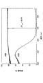
- FIG. 19 shows a cyclic voltammogram of the copper-iron PB complex (sweep speed: 1 mV / s).
- FIG. 19 shows that the waveform is a surface adsorption wave, suggesting that the water-dispersible copper-iron PB-type complex nanoparticle light control layer is stably present in the propylene carbonate solution.
- an oxidation peak electric potential exists in +0.86 [VvsAg / AgCl].
- the reduction peak potential was present at +0.81 [VvsAg / AgCl]. Therefore, the copper-iron PB type complex layer has a redox pair.
- Example 7 when a combination of a gas containing hydrogen and a gas containing ozone is used as the atmospheric gas, an oxidation-reduction pair (+0.86 V, +0.81 [VvsAg / AgCl]) should be used. Thus, it can be seen that the light control device exhibits gaschromic characteristics.
- FIG. 20 the light transmission spectrum of the light control multilayer glass of Example 7 is shown.
- the gas filling chamber S was supplied with a hydrogen atmosphere from the ozone state at room temperature for 2 minutes, and then the light transmittance was measured. As a result, it was found that the transmittance was changed (a transmittance change amount of 14.3% at a wavelength of 475 nm), and the light control multilayer glass of Example 7 had gaschromic characteristics.
- FIG. 21 shows the relationship between the change in the atmosphere in the gas filling chamber S (ozone and hydrogen) and the change in light transmittance. From FIG. 21, it was found that in the hydrogen atmosphere and ozone supply control, the maximum change in transmittance of light having a wavelength of 475 nm due to the hydrogen supply was 60.0% to 38.2%.
- a light control multilayer glass containing each of the metal complex layers (L1) to (L3) was produced in the same manner as in Example 1 except that the catalyst nanoplatinum particles were not used.
- the light control multilayer glasses of Comparative Examples 1 to 3 even when air or a hydrogen atmosphere was supplied to the gas filling chamber S, the oxidation-reduction reaction did not occur sufficiently, and the color change could not be visually recognized. For this reason, it was found that the light control multilayer glasses of Comparative Examples 1 to 3 did not have gaschromic properties. This is because the catalyst nano-platinum particles do not exist in the light control element, so that the spillover phenomenon does not occur, so the hydrogen molecule does not change well to a hydrogen atom, and further, from the hydrogen atom to a proton (H + ) and an electron (e This is because the change to-) does not occur well.
- the light transmittance in the oxidized state and reduced state of the light control multilayer glass was measured in the same manner as in Example 7 except that air was used instead of ozone.
- a gas chromic light control device having catalyst nanoparticles on the surface or inside of a PB type complex layer having gas chromic properties, and a film including the gas chromic light control device are formed on a substrate.
- the present invention relates to a gaschromic light control member and a PB-type complex light control multilayer glass. According to this embodiment, a gas chromic light control device can be produced using a PB type complex material.
- the light control device of this embodiment is inexpensive and can be manufactured at low cost because expensive nanoparticles need only be used in a very small amount.
- the light control element of this embodiment has high environmental resistance. Moreover, it can be produced by a simple process and the structure is simple. Therefore, according to the present invention, it is possible to realize a metal complex light control device, a metal complex light control member, and a metal complex light control multilayer glass excellent in performance and inexpensive.
- This embodiment is useful as a window material technique for controlling sunlight transmittance in buildings and vehicles.
Landscapes
- Physics & Mathematics (AREA)
- Nonlinear Science (AREA)
- General Physics & Mathematics (AREA)
- Optics & Photonics (AREA)
- Electrochromic Elements, Electrophoresis, Or Variable Reflection Or Absorption Elements (AREA)
Abstract
雰囲気ガスとの酸化還元反応により可逆的に光透過率が変化するガスクロミック特性を有する、下記一般式(1) AxMA[MB(CN)6]y・zH2O…(1) で表される金属錯体と、前記金属錯体の酸化還元反応を促進する触媒ナノ粒子層とを含む調光層を備えた調光素子であって、 前記雰囲気ガスが、水素を含有するガスと、酸素又はオゾンを含有するガスとの組合せである、調光素子。 [式中、Aは陽イオンを表し、MAは、バナジウム、クロム、マンガン、鉄、ルテニウム、コバルト、ロジウム、ニッケル、パラジウム、白金、銅、銀、亜鉛、ランタン、ユーロピウム、ガドリニウム、ルテチウム、バリウム、ストロンチウム、及びカルシウムからなる群より選ばれる一種又は二種以上の金属原子を表し、MBは、バナジウム、クロム、モリブデン、タングステン、マンガン、鉄、ルテニウム、コバルト、ニッケル、白金、及び銅からなる群より選ばれる一種又は二種以上の金属原子を表し、xは0~3の数であり、yは0.3~1.5の数であり、zは0~30の数である]
Description
本発明は、調光素子、調光部材、及び調光複層ガラスに関する。
一般に、建物において、窓は、光・熱が出入りする割合が大きい場所になっている。例えば、冬の暖房時に、窓から光・熱が流出する割合は、建物から流出する熱全体の5割程度であり、夏の冷房時に、窓から光・熱が流入する割合は、建物に流入する熱全体の7割程度である。したがって、窓における光・熱の出入りを適切に制御することにより、膨大な省エネルギー効果を得ることができる。調光ガラスは、このような目的で開発されたものであり、光・熱の流入・流出を制御する機能を有している。
調光ガラスには、いくつかの種類がある。それらのうち、電流・電圧の印加より、可逆的に光透過率が変化するガラスをエレクトロクロミック調光ガラスといい、温度により、可逆的に光透過率が変化するガラスをサーモクロミック調光ガラスといい、雰囲気ガスにより、可逆的に光透過率が変化するガラスをガスクロミック調光ガラスという。
例えば、調光層に酸化タングステン(WO3)薄膜を用いたエレクトロクロミック調光ガラスは現在、ほぼ実用化段階に達しており、市販品も出されている。また、ガスクロミック調光ガラスは、エレクトロクロミック調光ガラスに比べて、構造が複雑ではないので、低コストで製造することが可能な調光ガラスとして期待されている。そのため、ガスクロミック調光素子の材料や調光ガラスの構造について、多くの検討がなされてきた。
非特許文献1には、透明基材に、オキシ水酸化ニッケル粒子の表面にナノパラジウム粒子が付着している混合物の層が形成されてなるガスクロミック調光素子が記載されている。
特許文献1には、酸化タングステン(WO3)と、二酸化ケイ素中に分散したパラジウム粒子と含む調光材料を用いたガスクロミック調光素子が開示されている。
特許文献2には、マグネシウム・ジルコニウム合金薄膜を調光層として用いた多層薄膜からなる反射型調光薄膜材料が開示されている。ここで、反射型調光薄膜材料は、調光層の表面に、触媒層が形成されている構造、或いは、触媒層の上に、さらに保護層が形成されている構造を有する。また、反射型調光薄膜材料は、室温の20℃付近で水素化によって無色透明状態になるクロミック特性、或いは室温の20℃付近で脱水素化によって鏡状態になるクロミック特性を有する。
特許文献3には、プルシアンブルー型金属錯体粒子を用いたエレクトロクロミック素子の製作方法が開示されている。
Chih-Wei Hu; Yasusei Yamada; Kazuki Yoshimura, "Fabrication of nickel oxyhydroxide/palladium (NiOOH/Pd) nanocomposite for gasochromic application", Solar Energy Materials and Solar Cells, 2016, Issue 23, p.5390-5397
しかしながら、非特許文献1に記載のオキシ水酸化物を用いた調光素子では、通常の条件では酸化還元反応による色の変化が顕著でなく、また黒色と白色との間で色が変化するため、透明状態にならず、調光素子としての用途が限られていた。
また、特許文献1に記載の金属酸化物を用いた調光素子は耐久性が弱く、特許文献2に記載の金属合金を用いた調光素子は、耐候性が弱いことが知られている。
一方、特許文献3に記載されているようなエレクトロクロミック調光ガラスは、十分な光学特性を得るために、調光素子を5層程度の多層薄膜構造にする必要があり、透明導電膜のコストが非常に高くなってしまうという問題がある。また、プルシアンブルー型金属錯体は無機材料であり、耐候性に関し大きな問題はないと考えられているが、プルシアンブルー型金属錯体を有するエレクトロクロミック素子の電解質層には水系電解液又は有機溶媒系電解液が使用されており、いずれの場合も耐候性が問題となることがある。
本発明の一態様は、耐環境性に優れた、金属錯体を用いたガスクロミック調光素子を提供することを課題とする。
[1]雰囲気ガスとの酸化還元反応により可逆的に光透過率が変化するガスクロミック特性を有する、下記一般式(1)
AxMA[MB(CN)6]y・zH2O…(1)
で表される金属錯体と、前記金属錯体の酸化還元反応を促進する触媒ナノ粒子とを含む調光層を備えた調光素子であって、
前記雰囲気ガスが、水素を含有するガスと、酸素又はオゾンを含有するガスとの組合せである、調光素子。
[式中、Aは陽イオンを表し、MAは、バナジウム、クロム、マンガン、鉄、ルテニウム、コバルト、ロジウム、ニッケル、パラジウム、白金、銅、銀、亜鉛、ランタン、ユーロピウム、ガドリニウム、ルテチウム、バリウム、ストロンチウム、及びカルシウムからなる群より選ばれる一種又は二種以上の金属原子を表し、MBは、バナジウム、クロム、モリブデン、タングステン、マンガン、鉄、ルテニウム、コバルト、ニッケル、白金、及び銅からなる群より選ばれる一種又は二種以上の金属原子を表し、xは0~3の数であり、yは0.3~1.5の数であり、zは0~30の数である]
AxMA[MB(CN)6]y・zH2O…(1)
で表される金属錯体と、前記金属錯体の酸化還元反応を促進する触媒ナノ粒子とを含む調光層を備えた調光素子であって、
前記雰囲気ガスが、水素を含有するガスと、酸素又はオゾンを含有するガスとの組合せである、調光素子。
[式中、Aは陽イオンを表し、MAは、バナジウム、クロム、マンガン、鉄、ルテニウム、コバルト、ロジウム、ニッケル、パラジウム、白金、銅、銀、亜鉛、ランタン、ユーロピウム、ガドリニウム、ルテチウム、バリウム、ストロンチウム、及びカルシウムからなる群より選ばれる一種又は二種以上の金属原子を表し、MBは、バナジウム、クロム、モリブデン、タングステン、マンガン、鉄、ルテニウム、コバルト、ニッケル、白金、及び銅からなる群より選ばれる一種又は二種以上の金属原子を表し、xは0~3の数であり、yは0.3~1.5の数であり、zは0~30の数である]
[2]前記金属錯体の還元電位が-0.22[VvsAg/AgCl]以上であり、酸化電位が+0.62[VvsAg/AgCl]以下であり、且つ前記雰囲気ガスが、水素を含有するガスと、酸素を含有するガスとの組合せであるか、又は
前記金属錯体の還元電位が-0.22[VvsAg/AgCl]以上であり、酸化電位が+0.62[VvsAg/AgCl]以上、+2.3[VvsAg/AgCl]以下であり、且つ前記雰囲気ガスが、水素を含有するガスと、オゾンを含有するガスとの組合せである、[1]に記載の調光素子。
前記金属錯体の還元電位が-0.22[VvsAg/AgCl]以上であり、酸化電位が+0.62[VvsAg/AgCl]以上、+2.3[VvsAg/AgCl]以下であり、且つ前記雰囲気ガスが、水素を含有するガスと、オゾンを含有するガスとの組合せである、[1]に記載の調光素子。
[3]前記調光層が、前記金属錯体を含む層と、前記触媒ナノ粒子を含む層とが積層されてなることを特徴とする[1]又は[2]に記載の調光素子。
[4]前記触媒ナノ粒子を含む層の膜厚が2nm以上100nm以下である[3]に記載の調光素子。
[5]前記調光層が、前記触媒ナノ粒子が、前記金属錯体中に分散されてなることを特徴とする[1]又は[2]に記載の調光素子。
[6]前記金属錯体が、前記金属原子MA及び前記金属原子MBの間をシアノ基(CN)が架橋してなる金属錯体の結晶であり、該結晶の周囲に金属原子MCの陽イオン及び/又は金属原子MDを中心金属とする金属シアノ錯体陰イオンを結合させたものを配置したことを特徴とする[1]乃至[5]のいずれか一に記載の調光素子。
[前記金属原子MCは、バナジウム、クロム、マンガン、鉄、ルテニウム、コバルト、ロジウム、ニッケル、パラジウム、白金、銅、銀、亜鉛、ランタン、ユーロピウム、ガドリニウム、ルテチウム、バリウム、ストロンチウム、及びカルシウムからなる群より選ばれる一種又は二種以上の金属原子であり、前記金属原子MDは、バナジウム、クロム、モリブデン、タングステン、マンガン、鉄、ルテニウム、コバルト、ニッケル、白金、及び銅からなる群より選ばれる一種又は二種以上の金属原子である]
[前記金属原子MCは、バナジウム、クロム、マンガン、鉄、ルテニウム、コバルト、ロジウム、ニッケル、パラジウム、白金、銅、銀、亜鉛、ランタン、ユーロピウム、ガドリニウム、ルテチウム、バリウム、ストロンチウム、及びカルシウムからなる群より選ばれる一種又は二種以上の金属原子であり、前記金属原子MDは、バナジウム、クロム、モリブデン、タングステン、マンガン、鉄、ルテニウム、コバルト、ニッケル、白金、及び銅からなる群より選ばれる一種又は二種以上の金属原子である]
[7]前記触媒ナノ粒子層は、パラジウム、パラジウム合金、白金、及び白金合金からなる群より選択される一種以上を含むことを特徴とする[1]1乃至[6]のいずれか一に記載の調光素子。
[8]前記触媒ナノ粒子の粒径が1nm以上100nm以下であることを特徴とする[1]1乃至[7]のいずれか一に記載の調光素子。
[9][1]1乃至[8]のいずれか一に記載の調光素子を含む膜が透明基材上に形成されていることを特徴とする調光部材。
[10]前記膜の膜厚が10nm以上2μm以下であることを特徴とする[9]に記載の調光部材。
[11]前記透明基材は、ガラス基材又はプラスチック基材であることを特徴とする[9]又は[10]に記載の調光部材。
[12]2枚以上のガラス基材を有し、
2枚の前記ガラス基材の間に、[1]乃至[8]のいずれか一に記載の調光素子を含む膜が形成されていることを特徴とする調光複層ガラス。
2枚の前記ガラス基材の間に、[1]乃至[8]のいずれか一に記載の調光素子を含む膜が形成されていることを特徴とする調光複層ガラス。
[13]前記2枚のガラス基材の間に、水素、オゾン、酸素又は空気を給排気する手段をさらに有することを特徴とする[12]に記載の調光複層ガラス。
本発明の一態様によれば、耐環境性に優れた、金属錯体を用いたガスクロミック調光素子を提供する。
次に、本発明を実施するための形態を説明するが、本発明の範囲を逸脱することなく、下記の実施形態に種々の変形及び置換を加えることができる。また、本明細書において、数値範囲を「~」を用いて表す場合は、特記した場合を除き、「~」の両端の数値を含む。
[調光素子]
図1に、本実施形態による調光素子10の一例を示す。本形態は、プルシアンブルー型金属錯体を用いた、いわゆるプルシアンブルー型金属錯体調光素子(以下、PB型錯体調光素子ともいう)である。調光素子10は、雰囲気ガスとの酸化還元反応により、可逆的に光透過率が変化する、即ち、無色(透明)状態と着色状態の間で、可逆的に変化するものである。そのため、本実施形態による調光素子は、光・熱の流入・流出を制御する調光ガラスに好適に用いることができる。
図1に、本実施形態による調光素子10の一例を示す。本形態は、プルシアンブルー型金属錯体を用いた、いわゆるプルシアンブルー型金属錯体調光素子(以下、PB型錯体調光素子ともいう)である。調光素子10は、雰囲気ガスとの酸化還元反応により、可逆的に光透過率が変化する、即ち、無色(透明)状態と着色状態の間で、可逆的に変化するものである。そのため、本実施形態による調光素子は、光・熱の流入・流出を制御する調光ガラスに好適に用いることができる。
図1の例では、調光素子10は、金属錯体層10aの表面に、触媒ナノ粒子1bを含む触媒ナノ粒子層10bが付着してなる調光層(積層体)を備えている。触媒ナノ粒子層10bは、金属錯体層10aの酸化還元反応の触媒として機能する。
金属錯体層10aは、酸化状態にある場合には無色(透明)であり、還元状態にある場合には着色されるものであってよい。また、還元状態にある場合に無色となり、酸化状態にある場合に着色されるものであってもよい。なお、本実施形態においては、波長が400~870nmの光の透過率が変化することにより、無色(透明)状態と着色状態との間で変化し得る。本実施形態においては、材料によって波長700nm、420nm、475nmの光の透過率を測定することにより、無色(透明)状態と着色状態とを評価することができる。
プルシアンブルー型金属錯体(以下、単に金属錯体という場合がある)に色変化を起こさせる雰囲気ガスは、水素、酸素、オゾン等を含むガスとすることができる。雰囲気ガスとしては、少なくとも2つのガスの組合せ、すなわち金属錯体の還元を促すガスと、金属錯体の酸化を促すガスとの組合せを使用することができる。例えば、還元ガスとして水素を含むガスと、酸化ガスとして酸素を含むガスとを組み合わせて使用することができる。また、還元ガスとして水素を含むガスと、酸化ガスとしてオゾンを含むガスとの組合せを使用することができる。上記酸化ガスとしては、酸素及びオゾンを含むガスを使用することもでき、また空気を使用することもできる。
本実施形態においては、金属錯体層10aの還元電位が-0.22[VvsAg/AgCl]以上に存在し、酸化電位が+2.3[VvsAg/AgCl]以下に存在していると好ましい。これにより、後述の特定の雰囲気ガスに対するガスクロミック特性を有することができる。さらに、酸化電位が+0.62[VvsAg/AgCl]以下に存在している場合には、後述のように、酸化力がより低いガスを雰囲気ガスの酸化ガスとして用いることができる。なお、上記電位[VvsAg/AgCl]は、銀-塩化銀電極を基準にして測定された標準電位である。
なお、金属錯体の電気化学的特性を測定するため、所与の金属錯体の還元ピーク電位及び酸化ピーク電位をサイクリックボルタンメトリー(CV)により測定することができる。
還元電位が-0.22[VvsAg/AgCl]以上である金属錯体を備えた調光素子10を、水素を含む雰囲気に曝すと、金属錯体層10aの表面に付着している触媒ナノ粒子層10bの触媒作用により、金属錯体層10aが還元されて、波長が400~870nmの範囲で光の透過率が変化し、金属錯体層10aの色が変化する。
このとき、水素を含む雰囲気と、金属錯体調光素子10とにより、以下の反応が起こる。すなわち、金属錯体層10aが、その表面に付着している触媒ナノ粒子層10bの触媒作用によって、以下のように水素と反応する。
H2→2H++2e-(E=-0.22[VvsAg/AgCl])…(2)
ここで、Eは、酸化還元電位である。水素を含む雰囲気は、-0.22[VvsAg/AgCl]の還元能力を有するといえる。よって、金属錯体の還元電位が-0.22[VvsAg/AgCl]以上であれば、水素と良好に反応することができる。よって、還元ガスとして、水素を含むガスを用いることで、調光素子10に色変化を生じさせることができる。
一方、調光素子10を、空気等の酸素を含む雰囲気に曝すと、酸素と調光素子10とにより、以下の反応が起こる。
O2+2H2O+4e-→4OH-(E=+0.62[VvsAg/AgCl])…(3)
すなわち、酸素は、+0.62[VvsAg/AgCl]の酸化能力を有するといえる。そのため、金属錯体の酸化電位が+0.62[VvsAg/AgCl]以下であれば、酸素と良好に反応することができる。よって、酸化ガスとして酸素を含むガスを用いることで、調光素子10に色変化を生じさせることができる。
また、調光素子10を、オゾンを含む雰囲気に曝すと、オゾンと調光素子10とにより、以下の反応が起こる。
O3+2H++2e-=O2+H2O (E=+2.3[VvsAg/AgCl])…(4)
すなわち、オゾンは、+2.3[VvsAg/AgCl]という酸素より強い酸化能力を有するといえる。そのため、金属錯体の酸化電位が+0.62[VvsAg/AgCl]以上であっても、+2.3[VvsAg/AgCl]以下であれば、オゾンと良好に反応することができる。よって、酸化ガスとして、オゾンを含むガスを用いることで、調光素子10に色変化を生じさせることができる。
調光素子10は、金属錯体層10aと触媒ナノ粒子層10bとをそれぞれ、スピンコーターでコーティングすることにより作製することができる。また、塗布においては、スプレー法等のその他の湿式塗布法を利用することもできる。
上記コーティングの際には、金属錯体及び触媒ナノ粒子をそれぞれ、溶媒に分散させて分散液を調製して、その分散液を順にコートする。分散液の調製のために用いられる溶媒としては、特に限定されないが、水、メタノール、エタノール、有機溶剤等が挙げられる。中でも、水が好ましい。
[プルシアンブルー型金属錯体]
本実施形態では、プルシアンブルー型金属錯体(以下、「PB型錯体」と省略していうことがある。)の超微粒子を金属錯体層10aに含有させている。PB型錯体は、金属原子MA及び金属原子MBの間をシアノ基(CN)が架橋してなる結晶である。本明細書において、PB型錯体には、プルシアンブルー(以下、「PB」と省略していうことがある。)及びPBと同様の構造を有する類似物が含まれる。
本実施形態では、プルシアンブルー型金属錯体(以下、「PB型錯体」と省略していうことがある。)の超微粒子を金属錯体層10aに含有させている。PB型錯体は、金属原子MA及び金属原子MBの間をシアノ基(CN)が架橋してなる結晶である。本明細書において、PB型錯体には、プルシアンブルー(以下、「PB」と省略していうことがある。)及びPBと同様の構造を有する類似物が含まれる。
使用するPB型錯体としては、基本の組成式が、
AxMA[MB(CN)6]y・zH2O…(1)
として表されるものであればよい。式(1)中、Aは陽イオンであり、MA、MBはそれぞれ金属原子である。上式では、シアノ基(CN)の一部がヒドロキシル基、アミノ基、ニトロ基、ニトロソ基、水等で置換されていてもよい。
AxMA[MB(CN)6]y・zH2O…(1)
として表されるものであればよい。式(1)中、Aは陽イオンであり、MA、MBはそれぞれ金属原子である。上式では、シアノ基(CN)の一部がヒドロキシル基、アミノ基、ニトロ基、ニトロソ基、水等で置換されていてもよい。
式(1)中、金属原子MAは、バナジウム、クロム、マンガン、鉄、ルテニウム、コバルト、ロジウム、ニッケル、パラジウム、白金、銅、銀、亜鉛、ランタン、ユーロピウム、ガドリニウム、ルテチウム、バリウム、ストロンチウム、及びカルシウムからなる群より選ばれる一種又は二種以上の金属である。金属原子MAとしては鉄、コバルト、ニッケル、バナジウム、銅、マンガン、又は亜鉛が好ましく、鉄、銅、又はニッケルがより好ましい。金属原子MAに二種の金属の組み合わせを利用する場合には、鉄とニッケルとの組み合わせ、鉄と銅との組み合わせ、又はニッケルと銅との組み合わせが好ましく、鉄とニッケルとの組み合わせがより好ましい。
式(1)中、金属原子MBは、バナジウム、クロム、モリブデン、タングステン、マンガン、鉄、ルテニウム、コバルト、ニッケル、白金、及び銅からなる群より選ばれる一種又は二種以上の金属原子である。中でも金属原子MBとしては鉄、クロム、若しくはコバルトが好ましく、鉄が特に好ましい。金属原子MBについては、鉄とクロムとの組み合わせ、鉄とコバルトとの組み合わせ、又はクロムとコバルトとの組み合わせが好ましく、鉄とクロムとの組み合わせがより好ましい。
式(1)中、陽イオンAは必ずしも含有する必要はなく、含有している場合は、カリウム、ナトリウム、セシウム、ルビジウム、水素、アンモニアなどが挙げられるが、それに制限されるものではない。また、陰イオンなど他の材料を含有していてもよい。また、水(H2O)も必ずしも含有する必要はない。また、半分以上がこの組成式で表される構造を保っていれば、別の錯体等と混合していてもよい。例えば、光学応答性、触媒活性、分散性、基材への吸着性等の向上のために金属イオン、有機分子、別の金属錯体等を吸着させる場合もあるが、このような場合でも、色変化する部分の主たる構造が上記組成式であればよい。
式(1)中、xは0~3の数であり、0~1の数であることが好ましい。yは0.3~1.5の数であり、0.5~1の数であることが好ましい。zは0~30の数であり、5~15の数であることが好ましい。
上述のようにPB型錯体は、金属原子MA及び金属原子MBの間をシアノ基(CN)が架橋してなる結晶であるが、この結晶の周囲には、金属原子MCの陽イオン及び/又は金属原子MDを中心金属とする金属シアノ錯体陰イオンを結合させたものが配置されていてもよい。金属原子MCは、バナジウム、クロム、マンガン、鉄、ルテニウム、コバルト、ロジウム、ニッケル、パラジウム、白金、銅、銀、亜鉛、ランタン、ユーロピウム、ガドリニウム、ルテチウム、バリウム、ストロンチウム、及びカルシウムからなる群より選ばれる一種又は二種以上の金属原子であってよい。また、金属原子MDは、バナジウム、クロム、モリブデン、タングステン、マンガン、鉄、ルテニウム、コバルト、ニッケル、白金、及び銅からなる群より選ばれる一種又は二種以上の金属原子であってよい。
プルシアンブルー型金属錯体を含む調光層(調光素子)の製作方法としては、酸化還元反応が生じさせることができる調光層(調光素子)を作製できれば特に制限はないが、粒子を含む分散液を調製してその分散液を基板上に塗布する方法、電解析出により薄膜を形成する方法等が挙げられる。
粒子を含む分散液を調製して基板上に塗布する方法としては、特許文献3に記載の方法の他、逆ミセル法、フェリチンなどをテンプレートとして用いる方法、過剰のヘキサシアノ金属イオンと金属イオンの水溶液を混合する手法等が挙げられる。しかし、塗布の手法は上記のものに限られず、PB型錯体粒子が溶媒に分散した状態を得ることができればその製法、金属錯体の形状、分散の状態等は問わない。PB型錯体の粒径としては、溶媒に均一に分散するために直径500nm以下が望ましく、さらには直径200nm以下が望ましい。平均粒径の下限は特にないが、製法上3nm以上であることが実際的である。なお、本明細書における粒径は、動的光散乱法(光子相関法)によって求められた粒度分布のメジアン径である。
上記金属錯体粒子の表面には、分散性を向上させるための修飾分子が吸着していてもよい。かかる観点から金属錯体層10aに、アミノ基を有する化合物を上記金属錯体と共存させることが好ましい。このときアミノ基を有する化合物はイオンの状態であってもよい。例えば、有機溶媒、又はブタノール等のアルコールを利用する場合には、アミノ基を有する化合物を用いることが望ましく、特にアミノ基とアルキル基(好ましくは炭素数3~100、より好ましくは3~30であり、さらに好ましくは炭素数3~16)との双方を有する化合物であると望ましい。具体的には、オレイルアミン、ステアリルアミン、プロピルアミン、ヘキシルアミン等が望ましく、特にオレイルアミン、ヘキシルアミン、プロピルアミンが望ましい。
水を分散媒とするPB型錯体の分散液を得る場合には、フェロシアン化物イオン、フェリシアン化物イオン等を含むことが望ましい。また、ブタノール等のアルコールを分散媒とするPB型錯体の分散液を得る場合には、上記アミンと上記イオンとの両方を吸着させることも望ましく、特にプロピルアミンと、フェロシアン化物イオン又はフェリシアン化物イオンとの組み合わせが望ましい。分散液における超微粒子の濃度は特に限定されないが、良好な塗布及び製膜性を考慮すると、塗布法によって適当な濃度に調整する必要がある。例えば、スピンコート法によって塗布を行う場合には、1質量%以上50質量%以下であることが好ましく、スプレー法を利用する場合には、0.1質量%以上15質量%以下が好ましい。
[触媒ナノ粒子]
触媒ナノ粒子1bを構成する材料としては、用いられるPB型錯体の酸化還元反応の触媒として機能すれば、特に限定されないが、パラジウム、パラジウム合金、白金、白金合金等が挙げられ、二種以上併用してもよい。
触媒ナノ粒子1bを構成する材料としては、用いられるPB型錯体の酸化還元反応の触媒として機能すれば、特に限定されないが、パラジウム、パラジウム合金、白金、白金合金等が挙げられ、二種以上併用してもよい。
触媒ナノ粒子1bの粒径をナノサイズとすることにより、単位体積当たりの表面積が増加することから、例えばミクロンオーダーの粒子と比較して触媒能を向上させることができる。触媒ナノ粒子1bの平均粒径は、1nm以上100nm以下であることが好ましく、2nm以上30nm以下であるとより好ましい。
触媒ナノ粒子1bは、その表面に保護層が形成されていることが好ましい。保護層を構成する化合物としては、水溶性高分子や、アミノ基、チオール基を有する化合物等が挙げられる。
上記の水溶性高分子としては、特に限定されないが、ポリビニルピロリドン、ポリオール等が挙げられる。また、アミノ基、チオール基としては、特に限定されないが、例えば、下記一般式(5)
R1-NH2 …(5)
[式中、R1は炭素数2~20の一価の基で、飽和炭化水素基又は不飽和炭化水素基を示す。]
で表されるアミンを挙げることができ、アミンの具体例としては下記式(6)で表される化合物を挙げることができる。
R1-NH2 …(5)
[式中、R1は炭素数2~20の一価の基で、飽和炭化水素基又は不飽和炭化水素基を示す。]
で表されるアミンを挙げることができ、アミンの具体例としては下記式(6)で表される化合物を挙げることができる。

触媒ナノ粒子1bの合成方法としては、特に限定されないが、化学還元法、溶液法等が挙げられる(例えば、Synthesis of monodisperse Au, Pt, Pd, Ru and Ir nanoparticles in ethylene glycol、Bonet, F; Delmas, V; Grugeon, S; Herrera Urbina, R; Silvert, P-Y et al. (1999), Nanostructured Materials vol. 11 (8) p. 1277-1284、及びSize Control and Growth Process of Alkylamine-Stabilized Platinum Nanocrystals: A Comparison between the Phase Transfer and Reverse Micelles Methods, Kjell Wikander, Christophe Petit, Krister Holmberg, and Marie-Paule Pileni, Langmuir, 2006, 22 (10), pp 4863-4868等を参照)。
例えば、150℃の反応槽中に、主成分としての、白金を含む金属化合物の水溶液と、保護層を構成する材料としての水溶性高分子のエチレングリコール溶液とを反応させることにより、ナノ白金粒子を合成することができる。
より具体的な例においては、塩化白金(IV)(H2PtCl6)50mgと、水10mlと、ポリビニルピロリドン(PVP)20mgと、1.5M水酸化ナトリウム(NaOH)エチレングリコール溶液40mlを撹拌しながら混合した後、150℃で2時間反応させ、ナノ白金粒子の分散液を得ることができる。このとき、反応前の液は、薄い黄色を呈しているが、ナノ白金粒子が生成すると、液は、濃い茶色に変化する。粒径分布分析装置Photal ELSZ-1000(大塚電子社製)を用いて、ナノ白金粒子の平均粒径を測定することができる。上述の合成によって、ナノ白金粒子の平均粒径は1.5nmとなり得、粒径分布は非常に狭く、粒径はほぼ均一となり得る。
ナノ白金粒子の合成化学反応式を以下に示す。
2(CH2OH)2→2CH3CHO+2H2O・・・(7)
2CH3CHO+Pt4++5OH-+H2O→CH3COO-+6H2O+Pt・・・(8)
2CH3CHO+Pt4++5OH-+H2O→CH3COO-+6H2O+Pt・・・(8)
白金ナノ粒子の他の合成法は、例えば、室温の反応槽中に、主成分としての白金を含む金属化合物のトルエン有機溶液、保護層を構成する材料としてのドデシルアミンのトルエン溶液、及び水素化ホウ素ナトリウム還元剤(NaBH4)を反応させることにより、ナノ白金粒子を合成することができる。
より具体的な例においては、室温の反応槽中で、塩化白金(IV)(H2PtCl6)104mgと、水10ml、トルエン30mlと相転移触媒テトラ(デシル)アンモニウムブロミド(tetra(decyl)ammonium bromide)330mgを混合し、30分攪拌することができる。これにより、本来水層に存在する白金イオンが相転移触媒の効果によってトルエン有機層に変化し得る。その後、ナノ粒子保護層を構成する材料としてドデシルアミン(dodecylamine)690mgを投入し、1時間攪拌することで、トルエン層が呈していた元々のオレンジ色が、均一な乳白色に変化し得る。最後に、水素化ホウ素ナトリウム還元剤(NaBH4)125mgを投入し、反応させることにより、有機溶剤トルエンに分散するナノ白金粒子を合成することができる。このような合成によって、ナノ白金粒子の平均粒径は2.6nmとなり得、粒径分布は非常に狭く、粒径はほぼ均一となり得る。
触媒ナノ白金粒子1bを金属錯体層10a上に塗布する方法としては、特に限定されない、例えば、乾燥した金属錯体層10aの表面に、水又トルエン溶媒の1wt%触媒ナノ白金粒子1bを滴下し、スピンコート法により均一な分散した触媒ナノ白金粒子1bを金属錯体層10aの表面に作成することができる。触媒ナノ白金粒子1bを塗布する他の方法は、例えば、乾燥した金属錯体層10aの表面に吹き付けるスプレーコート法が挙げられる。
金属錯体層10aの表面に、触媒ナノ白金粒子1bを含む触媒ナノ白金粒子層10bが付着して調光層を構成してなる調光素子10を、水素を含む雰囲気に曝すと、調光層の色が無色に変化する。具体的には、金属錯体としてプルシアンブルーを用いた場合には、青色から無色に変化する。また、金属錯体としてニッケル-鉄PB型錯体を用いた場合には黄色から無色に変化し、銅-鉄PB型錯体を用いた場合には茶色から無色に変化する。
[調光部材]
図2に、本実施形態の一例として、調光部材30を示す。調光部材30は、ガラス基材20と、ガラス基材20上に形成された調光素子10とを含む。
図2に、本実施形態の一例として、調光部材30を示す。調光部材30は、ガラス基材20と、ガラス基材20上に形成された調光素子10とを含む。
調光素子10の膜厚(図示の例では、金属錯体層10aの膜厚と触媒ナノ粒子層10bの膜厚との合計)は、10nm以上2μm以下であることが好ましく、50nm以上1μm以下であることがより好ましい。調光素子10の膜厚が10nm以上2μm以下であると、調光素子10の色の変化を視認しやすくなる。なお、図1のように調光素子10が、金属錯体層10aと触媒ナノ粒子層10bとを含む場合には、触媒ナノ粒子層10bの厚さは、2nm以上100nm以下であることが好ましく、5nm以上70nm以下であることがより好ましい。
調光素子10の膜は、湿式塗布法により形成することができる。これにより、表面積が大きい調光素子10の膜も高速で形成することができる。また、高価な真空装置等を用いないため、従来の無機材料や金属を用いる場合に比べて、非常に低コストで、調光部材30を製造することが可能となる。
湿式塗布法としては、特に限定されないが、スピンコート法、スプレーコート法、ディップコート法、ドロップコート法等が挙げられる。
基材20を構成する材料としては、可視光を透過すれば、特に限定されないが、ガラス基材、例えば、石英、サファイア、ニオブ酸リチウム等の酸化物等が挙げられる。ガラス基材の代わりに、プラスチック基材等の透明基材を用いてもよい。
プラスチック基材を構成する材料としては、可視光を透過すれば、特に限定されないが、ポリエチレンテレフタレート(PET)、アクリル樹脂等が挙げられる。プラスチック基材として、セロハンテープ等を用いてもよい。基材の形状としては、特に限定されないが、板状、シート状等が挙げられる。
上述の形態は、PB型錯体を含む層(金属錯体層)10aと、触媒粒子を含む層10bとが基板上で積層された構造となっているが、調光素子の形態は、このような積層構造に限られない。例えば、図4に示すように、PB型錯体と触媒とを混在させた構造とすることもできる。すなわち、金属錯体11a中に触媒ナノ粒子11bが分散されてなる調光層を備えた調光素子110とすることができる。この場合、図4に示すように、触媒ナノ粒子11bの一部が、調光層の表面に露出していてもよい。このような調光層は、金属錯体11aと触媒ナノ粒子11bとを含む分散液を調製し、上述したような湿式塗布法によって、基板120上に形成し、調光部材130を作製することができる。その場合、調光素子110の膜厚は、10nm以上2μm以下であると好ましく、50nm以上1μm以下であるとより好ましい。
このように、本形態による調光素子はエレクトロクロミック素子と異なり、電流を外部から導入する必要を有しない。そのため、エレクトロクロミック素子と比較し、大きな構造の自由度が生まれる。酸化還元を誘起するガスが適切に触媒に到達し、触媒とPB型錯体とがある程度接近して設置されていれば、本実施形態は図示のものに限定されない。例えば、PB型錯体を不織布などに担持し、さらに触媒粒子をその上に担持した構造等も挙げられる。
また、図示の例では基材(基板)20、120の形状は平板状であるが、基材は別の形状を有していてもよい。例えば球状の構造体の上に適切にPB型錯体と触媒とを具備させ、その上部に一定の空間を空けて封止し、その空間に色変化を制御するガスを導入することができれば、色変化が起こり、ガスクロミック方式の調光装置として機能することができる。
[調光複層ガラス]
図3に、本実施形態の調光複層ガラス70の一例を示す。調光複層ガラスは、2枚のガラス基材20、60の間に、調光素子10が形成されており、開口部がシール部材40により封止されている。
図3に、本実施形態の調光複層ガラス70の一例を示す。調光複層ガラスは、2枚のガラス基材20、60の間に、調光素子10が形成されており、開口部がシール部材40により封止されている。
ガス充填室Sには、予めアルゴンガスが封入されており、雰囲気制御器50により、水素、酸素又は空気を給排気することができる。例えば、雰囲気制御器50は、水を電気分解して水素又は酸素をガス充填室Sに給気し、真空ポンプを用いて、ガス充填室Sから水素又は酸素を排気することができる。
水素又は水素を含む気体がガス充填室Sに給気されると、調光素子10が還元されて、色が変化する。また、酸素又は、空気等の酸素を含む気体がガス充填室Sに給気されると、調光素子10が酸化されて、元の状態になる。
したがって、ガス充填室Sの雰囲気を雰囲気制御器50により制御することにより、調光素子10は、還元状態と酸化状態との間で可逆的に制御することができる。また、雰囲気制御器50による給排気を中断すると、還元状態又は酸化状態を保つことができる。これにより、ガスクロミック方式で調光することが可能な調光複層ガラスが得られる。
現在、住宅における調光複層ガラスの普及が進んできており、新築の家では、複層ガラスを使うことが主流になりつつある。複層ガラスの内側にPB型錯体を用いた調光素子を備えることで、内部の空間をスイッチング用のガス充填室Sとして利用することができる。
以下に、本発明を実施例に基づいてさらに詳細に説明するが、本発明はこれにより限定して解釈されるものではない。
<調製例1:水分散性PBナノ粒子の合成>
特許文献3に記載された方法と同様の方法で、PBナノ粒子及びその分散液を調製した。具体的には、以下のとおりである。
特許文献3に記載された方法と同様の方法で、PBナノ粒子及びその分散液を調製した。具体的には、以下のとおりである。
フェロシアン化ナトリウム・10水和物14.5gを水60mLに溶解した水溶液に、硝酸鉄・9水和物16.2gを水に溶解した水溶液30mLを混合し、5分間攪拌した。析出した青色の沈殿物を遠心分離し、これを水で3回、続いてメタノールで1回洗浄し、減圧下で乾燥した。収量は11.0gであり、収率はFe4[Fe(CN)6]3・15H2Oとして、97.4%であった。
得られたPB(凝集体)0.40gを水8mLに懸濁させた。この懸濁液に、フェロシアン化ナトリウム・10水和物180mgを加え、攪拌したところ青色透明溶液ないし分散液へと変化した。PBのナノ粒子の分散液(A1)を得た。
<調製例2:水分散性ニッケル-鉄PB型錯体ナノ粒子の合成>
調製例1において、鉄塩をニッケル塩に変更することにより、水分散性ニッケル-鉄PB型錯体ナノ粒子及びその分散液を調製した。具体的には以下のとおりである。
調製例1において、鉄塩をニッケル塩に変更することにより、水分散性ニッケル-鉄PB型錯体ナノ粒子及びその分散液を調製した。具体的には以下のとおりである。
フェリシアン化カリウム25.3gを水80mLに溶解した溶液と、硝酸ニッケル・6水和物33.6gを水20mLに溶解した溶液を一気に混合し、5分間攪拌した。析出した黄褐色のニッケル-鉄型錯体ナノ粒子の沈殿物を遠心分離で取り出し、これを水で3回、続いてメタノールで1回洗浄し、減圧下で乾燥した。収量は30.0gであり、収率はNi3[Fe(CN)6]2・10H2Oとしてほぼ100%であった。
得られた凝集体0.30gを水10mLに懸濁させ、この懸濁液に、フェロシアン化ナトリウム・10水和物150mgを添加することで、ニッケル-鉄PB型錯体ナノ粒子を水に分散させた分散液(A2)を得た。
<調製例3:水分散性銅-鉄PB型錯体ナノ粒子の合成>
調製例1において、鉄塩を銅塩に変更することにより、水分散性銅-鉄PB型錯体ナノ粒子及びその分散液を調製した。具体的には以下のとおりである。
調製例1において、鉄塩を銅塩に変更することにより、水分散性銅-鉄PB型錯体ナノ粒子及びその分散液を調製した。具体的には以下のとおりである。
フェリシアン化カリウム1.98g(6mmol)を水に溶解させた溶液と、塩化銅に水和物1.53g(9mmol)を水に溶解した溶液を一気に混合し、5分間攪拌した。析出した茶色の銅-鉄PB型錯体ナノ粒子の沈殿物を遠心分離で取り出し、これを水で3回、続いてメタノールで1回洗浄し、減圧下で乾燥した。収量は2.5gであり、収率はCu3[Fe(CN)6]2・10H2Oとしてほぼ100%であった。
得られた凝集体2.0gを水10mLに懸濁させ、フェロシアン化ナトリウム0.634g(1.5mmol)を溶解させた水を添加し、銅-鉄PB型錯体ナノ粒子を水に分散させた分散液(A3)を得た。
<調製例4:トルエン分散性触媒ナノ白金粒子の合成>
塩化白金(IV)(H2PtCl6)104mgと、水10mlと、テトラ(デシル)アンモニウムブロミド(C40H84BrN)330mgと、トルエン30mlとを撹拌しながら混合した後、室温で2時間反応させたところ、白金成分が水相から有機相に転移した。さらに、ドデシルアミン(C12H27N)690mgを入れて撹拌したところ、溶液は白色になった。還元剤水素化ホウ素ナトリウム(NaBH4)125mgを入れて撹拌し、トルエン分散性を有するナノ白金粒子の分散液(B1)を得た。このとき反応前の溶液は、薄い黄色を呈していたが、ナノ白金粒子が生成すると、液は濃い茶色に変化した。
塩化白金(IV)(H2PtCl6)104mgと、水10mlと、テトラ(デシル)アンモニウムブロミド(C40H84BrN)330mgと、トルエン30mlとを撹拌しながら混合した後、室温で2時間反応させたところ、白金成分が水相から有機相に転移した。さらに、ドデシルアミン(C12H27N)690mgを入れて撹拌したところ、溶液は白色になった。還元剤水素化ホウ素ナトリウム(NaBH4)125mgを入れて撹拌し、トルエン分散性を有するナノ白金粒子の分散液(B1)を得た。このとき反応前の溶液は、薄い黄色を呈していたが、ナノ白金粒子が生成すると、液は濃い茶色に変化した。
得られた溶液を分液ロートで水200mlとを混合し、上層のトルエンを収集した。上層トルエンと400mlエタノールを混合し、-18℃の冷凍庫に24時間保存し、これにより、有機溶剤分散性を有するナノ白金粒子が沈殿した。このナノ白金粒子をトルエンに分散させ、0.2wt%の溶液を得た。粒径分布分析装置(Photal ELSZ-1000、大塚電子社製)を用いて、ナノ白金粒子の平均粒径を測定したところ、2.6nmであった。
<調製例5:エチレングリコール分散性触媒ナノ白金粒子の合成>
塩化白金(IV)(H2PtCl6)50mgと、水10mlと、ポリビニルピロリドン(PVP)20mgと、エチレングリコール溶液40mlとを撹拌しながら混合した後、150℃で2時間反応させ、エチレングリコール分散性を有するナノ白金粒子の分散液(B2)を得た。このとき、反応前の液は、薄い黄色を呈していたが、ナノ白金粒子が生成すると、液は濃い茶色に変化した。ナノ白金粒子の平均粒径を測定したところ、1.5nmであった。
塩化白金(IV)(H2PtCl6)50mgと、水10mlと、ポリビニルピロリドン(PVP)20mgと、エチレングリコール溶液40mlとを撹拌しながら混合した後、150℃で2時間反応させ、エチレングリコール分散性を有するナノ白金粒子の分散液(B2)を得た。このとき、反応前の液は、薄い黄色を呈していたが、ナノ白金粒子が生成すると、液は濃い茶色に変化した。ナノ白金粒子の平均粒径を測定したところ、1.5nmであった。
ナノ白金粒子の合成化学反応式を以下に示す。
2(CH2OH)2→2CH3CHO+2H2O…(7)
2CH3CHO+Pt4++5OH-+H2O→CH3COO-+6H2O+Pt…(8)
<調製例6:PB型錯体とエチレングリコール分散性触媒ナノ白金粒子との混合液調製>
調製例1で調製したPBナノ粒子分散液(A1)(濃度9wt%)5.0mlと、調製例5のナノ白金粒子の分散液(B2)1mlとを2時間撹拌し、混合液(C1)を得た。
調製例1で調製したPBナノ粒子分散液(A1)(濃度9wt%)5.0mlと、調製例5のナノ白金粒子の分散液(B2)1mlとを2時間撹拌し、混合液(C1)を得た。
<調製例7:PB型錯体とエチレングリコール分散性触媒ナノ白金粒子の混合液調製>
調製例1で調製したPBナノ粒子分散液(A1)5.0mlと、調製例5のナノ白金粒子との分散液(B2)1mlと、電解質であるカリウムビス(トリフルオロメタンスルホニル)イミド(K-TFSI)0.15gとを、2時間撹拌し、混合液(C2)を得た。
調製例1で調製したPBナノ粒子分散液(A1)5.0mlと、調製例5のナノ白金粒子との分散液(B2)1mlと、電解質であるカリウムビス(トリフルオロメタンスルホニル)イミド(K-TFSI)0.15gとを、2時間撹拌し、混合液(C2)を得た。
<作製例1:PBナノ粒子金属錯体層のスピンコート製膜>
調製例1で調製したPBナノ粒子分散液(A1)(濃度9wt%)を、ガラス基板(縦3.0cm、横3.0cm、厚さ1.1mm)の上にスピンコートすることによって、金属錯体層(L1)を製作した。具体的には、スピンコーターにガラス基板を設置し、分散液(A1)を0.1ml滴下し、1500rpmでの回転で10秒、続いて2000rpmでの回転で10秒でスピンコートを行った。これを30分間、約25℃の大気中で静置して、PBナノ粒子を含む調光層を作製した。触針段差計((株)ケーエルエー・テンコール製、触針式段差計:α-STEP(商品名))を用いて膜厚を測定したところ、約200nmであった。
調製例1で調製したPBナノ粒子分散液(A1)(濃度9wt%)を、ガラス基板(縦3.0cm、横3.0cm、厚さ1.1mm)の上にスピンコートすることによって、金属錯体層(L1)を製作した。具体的には、スピンコーターにガラス基板を設置し、分散液(A1)を0.1ml滴下し、1500rpmでの回転で10秒、続いて2000rpmでの回転で10秒でスピンコートを行った。これを30分間、約25℃の大気中で静置して、PBナノ粒子を含む調光層を作製した。触針段差計((株)ケーエルエー・テンコール製、触針式段差計:α-STEP(商品名))を用いて膜厚を測定したところ、約200nmであった。
<作製例2:ニッケル-鉄PB型錯体層のドロップコート製膜>
調製例2で調製したニッケル-鉄PB型錯体ナノ粒子分散液(A2)(濃度8wt%)を用いた。具体的には、ガラス基板(縦3.0cm、横3.0cm、厚さ1.1mm)を設置し、分散液2を30μl滴下し、分散液2を基板表面に徐々に乾燥する。これを120分間、約25℃の大気中で静置して、ニッケル-鉄PB型錯体ナノ粒子を含む金属錯体層(L2)を作製した。作製例1と同様に膜厚を測定したところ、約350nmであった。
調製例2で調製したニッケル-鉄PB型錯体ナノ粒子分散液(A2)(濃度8wt%)を用いた。具体的には、ガラス基板(縦3.0cm、横3.0cm、厚さ1.1mm)を設置し、分散液2を30μl滴下し、分散液2を基板表面に徐々に乾燥する。これを120分間、約25℃の大気中で静置して、ニッケル-鉄PB型錯体ナノ粒子を含む金属錯体層(L2)を作製した。作製例1と同様に膜厚を測定したところ、約350nmであった。
<作製例3:銅-鉄PB型錯体層のスピンコート製膜>
調製例3で調製した銅-鉄PB型錯体ナノ粒子分散液(A3)(濃度5wt%)を用いて製膜を行った。具体的には、スピンコーターにガラス基板を設置し、分散液(A3)を0.2ml滴下し、500rpmでの回転を10秒、また1000rpmでの回転で10秒スピンコートを行った。これを30分間、約25℃の大気中で静置して、銅-鉄PB型錯体ナノ粒子を含む金属錯体層(L3)を作製した。作製例1と同様に膜厚を測定したところ、約400nmであった。
調製例3で調製した銅-鉄PB型錯体ナノ粒子分散液(A3)(濃度5wt%)を用いて製膜を行った。具体的には、スピンコーターにガラス基板を設置し、分散液(A3)を0.2ml滴下し、500rpmでの回転を10秒、また1000rpmでの回転で10秒スピンコートを行った。これを30分間、約25℃の大気中で静置して、銅-鉄PB型錯体ナノ粒子を含む金属錯体層(L3)を作製した。作製例1と同様に膜厚を測定したところ、約400nmであった。
(実施例1)
<調光部材の作製>
作製例1で作成した金属錯体層(L1)(図1の10a)の上に、スピンコート法により調製例4の分散液(B1)を塗付することによって触媒ナノ粒子層(図1の10b)を形成して、調光層の積層体を形成することにより、調光素子(図1の10)を作成した。具体的には、スピンコーター上に金属錯体層(L1)を、PBナノ粒子が上部になるように設置し、調製例4の分散液(B1)を0.2ml滴下し、1000rpmでの回転で10秒、さらに1500rpmでの回転で5秒スピンコートを行った。その後、30分間、約25℃の大気中で静置して、媒体を乾燥除去した。これにより、調光素子と基板とを含む調光部材を作製した。なお、基板上に形成された調光素子全体の膜厚は、約210nmであった。
<調光部材の作製>
作製例1で作成した金属錯体層(L1)(図1の10a)の上に、スピンコート法により調製例4の分散液(B1)を塗付することによって触媒ナノ粒子層(図1の10b)を形成して、調光層の積層体を形成することにより、調光素子(図1の10)を作成した。具体的には、スピンコーター上に金属錯体層(L1)を、PBナノ粒子が上部になるように設置し、調製例4の分散液(B1)を0.2ml滴下し、1000rpmでの回転で10秒、さらに1500rpmでの回転で5秒スピンコートを行った。その後、30分間、約25℃の大気中で静置して、媒体を乾燥除去した。これにより、調光素子と基板とを含む調光部材を作製した。なお、基板上に形成された調光素子全体の膜厚は、約210nmであった。
図5に、上述のようにして得られた実施例1の調光部材における調光素子のFT-IRスペクトルを示す。プルシアンブルーに起因する吸収ピーク(2078cm-1)が観測されていることが分かる。実施例1の調光部材は、青色の均一な膜となった。上記調光素子のFT-IRスペクトルは、FT-IRフーリエ変換近赤外/中赤外/遠赤外分光分析装置(パーキンエルマージャパン社製、Frontier(商標))を用いて測定した。
図6に、実施例1の調光素子のFe2pとPt4f周辺のX線光電子分光スペクトルの積算強度対薄膜の深さを示す。調光素子のX線光電子分光スペクトルの測定は、X線光電子分光装置(Theta Probe Angle-Resolved Spectrometer system、サーモフィッシャーサイエンティフィック社製)を用いて行った。図5から、実施例1における調光素子の表面に、白金ナノ粒子が存在することが確認されたことが分かる。
<PB型錯体の電気化学特性>
本実施例で用いたPB型錯体(プルシアンブルー)の電気化学特性を測定した。調製例1で調製したPB型錯体ナノ粒子分散液(A1)(濃度9wt%)を用いて、100μlを3cm×3cmのITO膜付きガラス基板のITO膜上にスピンコートし、膜厚200nmの金属錯体層(PBナノ粒子調光層)を形成した。
本実施例で用いたPB型錯体(プルシアンブルー)の電気化学特性を測定した。調製例1で調製したPB型錯体ナノ粒子分散液(A1)(濃度9wt%)を用いて、100μlを3cm×3cmのITO膜付きガラス基板のITO膜上にスピンコートし、膜厚200nmの金属錯体層(PBナノ粒子調光層)を形成した。
形成された金属錯体層(PBナノ粒子調光層)を作用電極とし、Ag/AgCl電極を参照電極とし、白金線を対極とした三極式セルで、0.1Mのカリウムビス(トリフルオロメタンスルホニル)イミド(K+TFSI-)を電解質とし、炭酸プロピレン溶液中で、サイクリックボルタンメトリー(CV)を実施した。水分散性PBナノ粒子調光層は、炭酸プロピレンに不溶である。
図7に、上記の金属錯体層(PBナノ粒子調光層)のサイクリックボルタモグラムを示す(掃引速度:1mV/s)。図7では、波形が表面吸着波となっており、金属錯体層が炭酸プロピレン溶液中で安定に存在していることが示唆されている。また、酸化ピーク電位が、少なくとも+0.1[VvsAg/AgCl]、及び+0.3[VvsAg/AgCl]に存在していることが分かる。一方、還元ピーク電位が、少なくとも-0.05[VvsAg/AgCl]、及び+0.28[VvsAg/AgCl]に存在している。よって、上記の金属錯体は、少なくとも2つの酸化還元対を有する。
このように、調製例1で得られたPB型錯体(プルシアンブルー)においては、還元電位が-0.22[VvsAg/AgCl]以上に存在し、酸化電位が+0.62[VvsAg/AgCl]以下に存在することが分かった。
<調光複層ガラスの作製及び光透過特性の測定>
上記の調光部材とガラス基板とを組み合わせて、図3を参照して上述したような調光複層ガラスを作製し、調光複層ガラスの光透過率を測定した。測定には、光源80と分光光度計90備えた光学装置(図8)を用いた。
上記の調光部材とガラス基板とを組み合わせて、図3を参照して上述したような調光複層ガラスを作製し、調光複層ガラスの光透過率を測定した。測定には、光源80と分光光度計90備えた光学装置(図8)を用いた。
具体的には、図8に示すように、光源80と分光光度計90との間に、調光複層ガラス70の調光部材30をその各面がガラス基材60に対向するように配置した後、開口部をシール部材40により封止し、調光複層ガラスの光透過率を測定した。
図7に示すように、ガス充填室Sにガスを給排気するために、雰囲気制御器50を設置した。また、ガラス基材20としては、シリカガラス基板を用いた。また、分光光度計90として、USB4000(Ocean optics社製)を用いた。
図9に、実施例1の調光複層ガラスの光透過スペクトルを示す。図9において、酸化状態及び還元状態における光透過スペクトルは、それぞれ空気及び水素の含有量が100%である雰囲気(以下、水素雰囲気という)をガス充填室Sに室温で1分間給気した後、室温で測定したものである。
図9より、実施例1の調光複層ガラスは、酸化状態及び還元状態で、波長が700nmの光の透過率が大きく変化しており(透過率変化量76.6%)、高性能なガスクロミック特性を有することが分かる。
次に、ガス充填室Sに水素雰囲気を30秒間給気した後、水素雰囲気の給気を30秒間停止した。ここで、水素雰囲気の給気を停止すると、開口部からガス充填室Sに空気が流入する。これを1サイクルとする水素雰囲気の給気制御を4回繰り返し、その間1秒毎に、波長が700nmの光の透過率を測定した。
図10Aに、ガス充填室Sの雰囲気の変化と光透過率の変化との関係を示す。図10Aより、1回目の水素雰囲気の給気制御では、水素の給気によって、波長が700nmの光の透過率が12.0%から88.6%に変化することが分かる。また、2~4回目の水素雰囲気の給気制御では、水素の給気を停止して空気を流入させることによって、波長が700nmの光の透過率が86.1%から15.9%に変化することが分かる。
図10Bに、長期評価実験の結果を示す。ガス充填室Sに水素雰囲気を60秒間給気した後、水素雰囲気の給気を120秒間停止するサイクルを繰り返した。380回目のサイクルで、水素雰囲気の給気停止によって透過率変化が76.6%から41.2%に変化した。
(実施例2)
<調光部材の作製>
作製例1で作成した金属錯体層(L1)を、ホットプレート上で、150℃30分ベーキングして、水分を除去した。この金属錯体層(L1)の上に、スピンコート法により調製例5で得られたナノ白金粒子の分散液(B2)の層を作製して、調光素子を得た。具体的には、スピンコーター上に金属錯体層(L1)をPBナノ粒子が上部になるように設置し、調製例5の分散液(B2)を0.2ml滴下し、スピンコートを500rpmでの回転で10秒行い、続いて1500rpmでの回転で5秒行った。これを5時間間、約25℃の大気中で静置して、媒体を乾燥除去した。これにより、調光素子と基板とを含む調光部材を作製した。なお、基板上に形成された調光素子の膜厚は、約200nmであった。
<調光部材の作製>
作製例1で作成した金属錯体層(L1)を、ホットプレート上で、150℃30分ベーキングして、水分を除去した。この金属錯体層(L1)の上に、スピンコート法により調製例5で得られたナノ白金粒子の分散液(B2)の層を作製して、調光素子を得た。具体的には、スピンコーター上に金属錯体層(L1)をPBナノ粒子が上部になるように設置し、調製例5の分散液(B2)を0.2ml滴下し、スピンコートを500rpmでの回転で10秒行い、続いて1500rpmでの回転で5秒行った。これを5時間間、約25℃の大気中で静置して、媒体を乾燥除去した。これにより、調光素子と基板とを含む調光部材を作製した。なお、基板上に形成された調光素子の膜厚は、約200nmであった。
<調光複層ガラスの作製及びその光透過特性の測定>
実施例1と同様に調光複層ガラスを作製し、実施例1と同様の光学装置を用い、同様の手法で光透過特性を測定した。
実施例1と同様に調光複層ガラスを作製し、実施例1と同様の光学装置を用い、同様の手法で光透過特性を測定した。
図11に、実施例2の調光複層ガラスの光透過スペクトルを示す。ガス充填室Sに水素雰囲気を室温で1分間給気した後、光の透過率を測定した。その結果、透過率が大きく変化しており(波長が700nmの透過率変化量72.0%)、実施例2の調光複層ガラスが高性能なガスクロミック特性を有すること分かる。
(実施例3)
<調光部材の作製>
調製例6で得られた混合液(C1)をスピンコート法で基板上に塗布し、PB型錯体を用いた調光素子を含む調光部材を作製した。塗布の方法及び膜厚の測定は、作製例2の金属錯体層(L1)の作製方法と同様に行った。基板上に形成された調光素子の膜厚は、約180nmであった。
<調光部材の作製>
調製例6で得られた混合液(C1)をスピンコート法で基板上に塗布し、PB型錯体を用いた調光素子を含む調光部材を作製した。塗布の方法及び膜厚の測定は、作製例2の金属錯体層(L1)の作製方法と同様に行った。基板上に形成された調光素子の膜厚は、約180nmであった。
図4に、実施例3の調光部材の一例を模式的に示す。本実施例の触媒ナノ粒子11bは、金属錯体11a中に分散しており、調光素子(調光層)110を形成している。調光部材130は、基材120と調光素子110とを含む。
<調光複層ガラスの作製及びその光透過特性の測定>
実施例1と同様に調光複層ガラスを作製し、実施例1と同様の光学装置を用い、同様の手法で光透過特性を測定した。
実施例1と同様に調光複層ガラスを作製し、実施例1と同様の光学装置を用い、同様の手法で光透過特性を測定した。
図12に、実施例3の調光複層ガラスの光透過スペクトルを示す。ガス充填室Sに水素雰囲気を室温で30分間給気した後、光の透過率を測定した。その結果、透過率が大きく変化しているので(波長が700nmの透過率変化量53.9%)、実施例3の調光複層ガラスが高性能なガスクロミック特性を有することが分かる。
(実施例4)
<調光部材の作製>
調製例7で得られた混合液(C2)をスピンコート法で基板上に塗布し、調光素子を含む調光部材を作成した。塗布の方法及び膜厚の測定は、作製例2の金属錯体層(L1)の作製と同様である。基板上に形成された調光素子の膜厚は、約250nmであった。
<調光部材の作製>
調製例7で得られた混合液(C2)をスピンコート法で基板上に塗布し、調光素子を含む調光部材を作成した。塗布の方法及び膜厚の測定は、作製例2の金属錯体層(L1)の作製と同様である。基板上に形成された調光素子の膜厚は、約250nmであった。
<複層ガラスの作製、及びその光透過特性の測定>
実施例1と同様に調光複層ガラスを作製し、実施例1と同様の光学装置を用い、同様の手法で光透過特性を測定した。
実施例1と同様に調光複層ガラスを作製し、実施例1と同様の光学装置を用い、同様の手法で光透過特性を測定した。
図13に、実施例4の調光複層ガラスの光透過スペクトルを示す。ガス充填室Sに水素雰囲気を室温で3分間給気した後、光の透過率を測定した。その結果、透過率が大きく変化しており(波長が700nmの透過率変化量82.1%)、実施例4の調光複層ガラスが高性能なガスクロミック特性を有することが分かる。
(実施例5)
<調光部材の作製>
作製例2で作製したニッケル-鉄PB型錯体層(L2)の上に、スピンコート法によって調製例4の分散液(B1)を塗付することによって、触媒ナノ粒子層を形成し、PB型錯体調光素子を含むPB型錯体調光部材を作製した。塗布の方法及び膜厚の測定は、実施例1と同様に行った。基板上に形成された調光素子の膜厚は、約400nmであった。
<調光部材の作製>
作製例2で作製したニッケル-鉄PB型錯体層(L2)の上に、スピンコート法によって調製例4の分散液(B1)を塗付することによって、触媒ナノ粒子層を形成し、PB型錯体調光素子を含むPB型錯体調光部材を作製した。塗布の方法及び膜厚の測定は、実施例1と同様に行った。基板上に形成された調光素子の膜厚は、約400nmであった。
<PB型錯体の電気化学特性>
本実施例で用いたPB型錯体(ニッケル-鉄PB型錯体)の電気化学特性を測定した。測定は、調製例2で調製したPB型錯体ナノ粒子分散液(A2)を用いたこと以外は、実施例1におけるPB型錯体(プルシアンブルー)の電気化学特性の測定と同様にして行った。
本実施例で用いたPB型錯体(ニッケル-鉄PB型錯体)の電気化学特性を測定した。測定は、調製例2で調製したPB型錯体ナノ粒子分散液(A2)を用いたこと以外は、実施例1におけるPB型錯体(プルシアンブルー)の電気化学特性の測定と同様にして行った。
図14に、得られた金属錯体層(ニッケル-鉄PB型錯体層)のサイクリックボルタモグラムを示す(掃引速度:1mV/s)。図14では、波形が表面吸着波となっており、金属錯体層が炭酸プロピレン溶液中で安定に存在していることが示唆されている。また、酸化ピーク電位が、+0.62[VvsAg/AgCl]、+0.78[VvsAg/AgCl]に存在していることが分かる。一方、還元ピーク電位が、+0.59[VvsAg/AgCl]、及び+0.72[VvsAg/AgCl]に存在している。よって、調製例2において得られた金属錯体は、少なくとも2つの酸化還元対を有する。
したがって、実施例5において、雰囲気ガスとして、水素を含むガスと酸素又は空気を含むガスとの組み合わせを使用した場合、第一の酸化還元対(+0.62V、+0.59[VvsAg/AgCl])を利用することで、調光部材がガスクロミック特性を示す。また、雰囲気ガスとして、水素を含むガスとオゾンを含むガスとの組み合わせを使用する場合は、第一の酸化還元対(+0.62V、+0.59[VvsAg/AgCl])、及び/又は第二の酸化還元対(+0.78V、+0.72[VvsAg/AgCl])を利用できる。オゾンは酸化還元電位が酸素よりも高く、空気より強い酸化能力を有するため、オゾンを用いた場合には、より大きな色変化が得られる。
<調光複層ガラスの作製及びその光透過特性の測定>
実施例1と同様に調光複層ガラスを作製し、実施例1と同様の光学装置を用い、同様の手法で光透過特性を測定した。
実施例1と同様に調光複層ガラスを作製し、実施例1と同様の光学装置を用い、同様の手法で光透過特性を測定した。
図15に、実施例5の調光複層ガラスの光透過スペクトルを示す。ガス充填室Sに空気中状態から水素雰囲気を室温で3分間給気した後、光の透過率を測定した。その結果、透過率が大きく変化しており(波長が400nmの透過率変化量28.7%)、実施例5の調光複層ガラスが優れたガスクロミック特性を有することが分かる。
次に、ガス充填室Sに水素雰囲気を60秒間給気した後、水素雰囲気の給気を120秒間停止した。ここで、水素雰囲気の給気を停止すると、開口部からガス充填室Sに空気が流入する。これを1サイクルとする水素雰囲気の給気制御を33回繰り返し、その間1秒毎に、波長が400nmの光の透過率を測定した。
図16に、ガス充填室Sの雰囲気の変化と光透過率の変化との関係を示す。図16より、1回目の水素雰囲気の給気制御では、水素の給気によって、波長が400nmの光の透過率が22.0%から57.3%に変化したことが分かる。また、2~33回目の水素雰囲気の給気制御では、水素給気を停止し、空気を流入させたことによって、波長が400nmの光の透過率が53.1%から27.8%に変化したことが分かる。
(実施例6)
<調光部材の作製>
実施例5と同様にして、PB型錯体を用いた調光素子を含む調光部材を作製した。
<調光部材の作製>
実施例5と同様にして、PB型錯体を用いた調光素子を含む調光部材を作製した。
<調光複層ガラスの作製及び光透過特性の測定>
図17に、実施例6の調光複層ガラスの光透過スペクトルを示す。ガス充填室Sにオゾンを満たした状態を構築し、その後、水素雰囲気を室温で1分間給気した後、光の透過率を測定した。オゾンの発生には、オゾン発生装置(SoecV350、マルコー社製)を用いた。また、オゾンの給気は、オゾン出力35mg/h、風量5L/minの条件で行った。
図17に、実施例6の調光複層ガラスの光透過スペクトルを示す。ガス充填室Sにオゾンを満たした状態を構築し、その後、水素雰囲気を室温で1分間給気した後、光の透過率を測定した。オゾンの発生には、オゾン発生装置(SoecV350、マルコー社製)を用いた。また、オゾンの給気は、オゾン出力35mg/h、風量5L/minの条件で行った。
上記測定の結果、透過率は、実施例5と比較してより大きく変化することが分かった(波長が400nmの透過率変化量38.1%)。つまり、雰囲気ガスとして水素及びオゾンを用いた実施例6の調光複層ガラスは、さらに良好なガスクロミック特性を有することが分かった。
次に、ガス充填室Sに水素雰囲気を2分間給気した後、オゾンを1分間給気した。これを1サイクルとする水素雰囲気及びオゾンの給気制御を15回繰り返し、その間1秒毎に、波長が400nmの光の透過率を測定した。
図18に、ガス充填室Sの雰囲気の変化(オゾンと水素)と光透過率の変化との関係を示す。図18より、水素雰囲気及びオゾン雰囲気の給気制御では、オゾンの給気によって、波長が400nmの光の透過率は68.0%から25.1%に変化したことが分かる。空気(酸素)に代えてオゾンを用いた場合、調光複層ガラスの光透過率のスイッチングに要する時間が大幅に減少すると共に、調光複層ガラスの光透過率の変化量が増大する。
(実施例7)
<調光部材の作製>
作製例3で作成した金属錯体層(L3)の上に、スピンコート法により調製例4で得られた分散液(B1)を塗付して、触媒ナノ白金粒子の層を形成し、調光素子を含む調光部材を作製した。塗布の方法及び膜厚の測定は、実施例1と同様に行った。基板上に形成された調光素子の膜厚は約400nmであった。
<調光部材の作製>
作製例3で作成した金属錯体層(L3)の上に、スピンコート法により調製例4で得られた分散液(B1)を塗付して、触媒ナノ白金粒子の層を形成し、調光素子を含む調光部材を作製した。塗布の方法及び膜厚の測定は、実施例1と同様に行った。基板上に形成された調光素子の膜厚は約400nmであった。
<PB型錯体の電気化学特性>
本実施例で用いたPB型錯体(銅-鉄PB型錯体)の電気化学特性を測定した。測定は、調製例2で調製した金属錯体ナノ粒子分散液(A2)を用いたこと以外は、実施例1におけるPB型錯体(プルシアンブルー)の電気化学特性の測定と同様にして行った。
本実施例で用いたPB型錯体(銅-鉄PB型錯体)の電気化学特性を測定した。測定は、調製例2で調製した金属錯体ナノ粒子分散液(A2)を用いたこと以外は、実施例1におけるPB型錯体(プルシアンブルー)の電気化学特性の測定と同様にして行った。
図19に、銅-鉄PB型錯体のサイクリックボルタモグラムを示す(掃引速度:1mV/s)。図19より、波形が表面吸着波となっていることが分かり、水分散性銅-鉄PB型錯体ナノ粒子調光層が炭酸プロピレン溶液中で安定に存在していることが示唆されている。また、酸化ピーク電位が、+0.86[VvsAg/AgCl]に存在していることが分かった。一方、還元ピーク電位は、+0.81[VvsAg/AgCl]に存在していた。よって、銅-鉄PB型錯体層は酸化還元対を有する。
このため、実施例7において、雰囲気ガスとして、水素を含むガスとオゾンを含むガスとの組み合わせを使用した場合、酸化還元対(+0.86V、+0.81[VvsAg/AgCl])を利用することにより、調光素子がガスクロミック特性を示すことが分かる。
<調光複層ガラスの作製及び光透過特性の測定>
図20に、実施例7の調光複層ガラスの光透過スペクトルを示す。ガス充填室Sにオゾン中状態から水素雰囲気を室温で2分間給気した後、光の透過率を測定した。その結果、透過率が変化しており(波長が475nmの透過率変化量14.3%)、実施例7の調光複層ガラスがガスクロミック特性を有することが分かった。
図20に、実施例7の調光複層ガラスの光透過スペクトルを示す。ガス充填室Sにオゾン中状態から水素雰囲気を室温で2分間給気した後、光の透過率を測定した。その結果、透過率が変化しており(波長が475nmの透過率変化量14.3%)、実施例7の調光複層ガラスがガスクロミック特性を有することが分かった。
次に、ガス充填室Sに水素雰囲気を2分間給気した後、オゾンを1分間給気した。これを1サイクルとする水素雰囲気及びオゾンの給気制御を17回繰り返し、その間1秒毎に、波長が400nmの光の透過率を測定した。オゾンの給気は、実施例6と同様にして行った。
図21に、ガス充填室Sの雰囲気の変化(オゾンと水素)と光透過率の変化との関係を示す。図21から、水素雰囲気及びオゾンの給気制御では、水素給気による、波長が475nmの光の透過率最大変化は60.0%から38.2%であることが分かった。
(比較例1~3)
<調光部材の作製>
作製例1~3で得られた金属錯体層(L1)~(L3)を用い、触媒ナノ白金粒子(分散液(B1))を使用しなかったこと以外は実施例1と同様にして、調光素子を作製した。
<調光部材の作製>
作製例1~3で得られた金属錯体層(L1)~(L3)を用い、触媒ナノ白金粒子(分散液(B1))を使用しなかったこと以外は実施例1と同様にして、調光素子を作製した。
<調光複層ガラスの作製及び光透過特性の測定>
触媒ナノ白金粒子を使用しなかったこと以外は、実施例1と同様にして、金属錯体層(L1)~(L3)それぞれを含む調光複層ガラスを作製した。
触媒ナノ白金粒子を使用しなかったこと以外は、実施例1と同様にして、金属錯体層(L1)~(L3)それぞれを含む調光複層ガラスを作製した。
比較例1~3の調光複層ガラスは、ガス充填室Sに空気又は水素雰囲気を給気しても、酸化還元反応が十分に起こらず、色の変化を視認することができなかった。このため、比較例1~3の調光複層ガラスは、ガスクロミック特性を有さないことが分かった。これは、調光素子中に触媒ナノ白金粒子が存在していないため、スピルオーバー現象が起こらないため水素分子が水素原子へ良好に変化せず、さらに水素原子からプロトン(H+)及び電子(e-)への変化も良好に起こらないためである。
(比較例4)
<調光部材の作製>
実施例7と同様にして、PB型錯体を用いた調光素子を含む調光部材を作製した。
<調光部材の作製>
実施例7と同様にして、PB型錯体を用いた調光素子を含む調光部材を作製した。
<調光複層ガラスのの作製及び光透過特性の測定>
実施例7と同様にして、調光複層ガラスを作製した。
実施例7と同様にして、調光複層ガラスを作製した。
オゾンの代わりに、空気を用いた以外は、実施例7と同様にして、調光複層ガラスの酸化状態及び還元状態の光透過率を測定した。
比較例4の調光複層ガラスは、ガス充填室Sに空気又は水素雰囲気を給気しても、酸化還元反応が十分に起こらず、色の変化を視認することができなかった。比較例4の複層ガラスは、ガスクロミック特性を有さないことが分かった。これは、比較例4における調光素子の酸化ピーク電位が+0.62[VvsAg/AgCl]以下に存在せず、水素及び酸素のガスの組合せに対応する酸化還元対が存在しないためと考えられる。
以上詳述したように、本実施形態は、ガスクロミック特性があるPB型錯体層の表面又は中に触媒ナノ粒子を有するガスクロミック調光素子、ガスクロミック調光素子を含む膜が基板上に形成されてなるガスクロミック調光部材、及びPB型錯体調光複層ガラスに係るものである。本実施形態により、PB型錯体材料を用いて、ガスクロミック調光素子を作製することができる。
また、本実施形態の調光素子は、安価であり、高価なナノ粒子はごく少量の使用で足りるため、低コストで作製することが可能である。さらに、本実施形態の調光素子は、耐環境性が高い。しかも簡便なプロセスで作製することができ、構造も簡単である。したがって、本発明により、性能に優れ且つ安価な金属錯体調光素子、金属錯体調光部材、及び金属錯体調光複層ガラスを実現することができる。
本実施形態は、建物や乗り物における太陽光透過率を制御するための窓材料技術として有用である。
本出願は、2017年3月1日に日本国特許庁に出願された特願2017-038803号に基づく優先権を主張するものであり、その全内容は参照をもってここに援用される。
1b 触媒ナノ粒子
10a、110a 金属錯体層
10b 触媒ナノ粒子層
10、110 調光素子(調光層)
11a 金属錯体
20 透明基材
30、130 調光部材
40 シール部材
50 雰囲気制御器
60 透明基材
70 調光複層ガラス
80 光源
90 分光光度計
S ガス充填室
10a、110a 金属錯体層
10b 触媒ナノ粒子層
10、110 調光素子(調光層)
11a 金属錯体
20 透明基材
30、130 調光部材
40 シール部材
50 雰囲気制御器
60 透明基材
70 調光複層ガラス
80 光源
90 分光光度計
S ガス充填室
Claims (13)
- 雰囲気ガスとの酸化還元反応により可逆的に光透過率が変化するガスクロミック特性を有する、下記一般式(1)
AxMA[MB(CN)6]y・zH2O…(1)
で表される金属錯体と、前記金属錯体の酸化還元反応を促進する触媒ナノ粒子とを含む調光層を備えた調光素子であって、
前記雰囲気ガスが、水素を含有するガスと、酸素又はオゾンを含有するガスとの組合せである、調光素子。
[式中、Aは陽イオンを表し、MAは、バナジウム、クロム、マンガン、鉄、ルテニウム、コバルト、ロジウム、ニッケル、パラジウム、白金、銅、銀、亜鉛、ランタン、ユーロピウム、ガドリニウム、ルテチウム、バリウム、ストロンチウム、及びカルシウムからなる群より選ばれる一種又は二種以上の金属原子を表し、MBは、バナジウム、クロム、モリブデン、タングステン、マンガン、鉄、ルテニウム、コバルト、ニッケル、白金、及び銅からなる群より選ばれる一種又は二種以上の金属原子を表し、xは0~3の数であり、yは0.3~1.5の数であり、zは0~30の数である] - 前記金属錯体の還元電位が-0.22[VvsAg/AgCl]以上であり、酸化電位が+0.62[VvsAg/AgCl]以下であり、且つ前記雰囲気ガスが、水素を含有するガスと、酸素を含有するガスとの組合せであるか、又は
前記金属錯体の還元電位が-0.22[VvsAg/AgCl]以上であり、酸化電位が+0.62[VvsAg/AgCl]以上、+2.3[VvsAg/AgCl]以下であり、且つ前記雰囲気ガスが、水素を含有するガスと、オゾンを含有するガスとの組合せである、請求項1に記載の調光素子。 - 前記調光層が、前記金属錯体を含む層と、前記触媒ナノ粒子を含む層とが積層されてなることを特徴とする請求項1に記載の調光素子。
- 前記触媒ナノ粒子を含む層の膜厚が2nm以上100nm以下である請求項3に記載の調光素子。
- 前記調光層が、前記触媒ナノ粒子が前記金属錯体中に分散されてなることを特徴とする請求項1に記載の調光素子。
- 前記金属錯体が、前記金属原子MA及び前記金属原子MBの間をシアノ基(CN)が架橋してなる金属錯体の結晶であり、該結晶の周囲に金属原子MCの陽イオン及び/又は金属原子MDを中心金属とする金属シアノ錯体陰イオンを結合させたものを配置したことを特徴とする請求項1に記載の調光素子。
[前記金属原子MCは、バナジウム、クロム、マンガン、鉄、ルテニウム、コバルト、ロジウム、ニッケル、パラジウム、白金、銅、銀、亜鉛、ランタン、ユーロピウム、ガドリニウム、ルテチウム、バリウム、ストロンチウム、及びカルシウムからなる群より選ばれる一種又は二種以上の金属原子であり、前記金属原子MDは、バナジウム、クロム、モリブデン、タングステン、マンガン、鉄、ルテニウム、コバルト、ニッケル、白金、及び銅からなる群より選ばれる一種又は二種以上の金属原子である] - 前記触媒ナノ粒子は、パラジウム、パラジウム合金、白金、及び白金合金からなる群より選択される一種以上を含むことを特徴とする請求項1に記載の調光素子。
- 前記触媒ナノ粒子の粒径が1nm以上100nm以下であることを特徴とする請求項1に記載の調光素子。
- 請求項1に記載の調光素子を含む膜が透明基材上に形成されていることを特徴とする調光部材。
- 前記膜の膜厚が10nm以上2μm以下であることを特徴とする請求項9に記載の調光部材。
- 前記透明基材は、ガラス基材又はプラスチック基材であることを特徴とする請求項9に記載の調光部材。
- 2枚以上のガラス基材を有し、
2枚の前記ガラス基材の間に、請求項1に記載の調光素子を含む膜が形成されていることを特徴とする調光複層ガラス。 - 前記2枚のガラス基材の間に、水素、オゾン、酸素又は空気を給排気する手段をさらに有することを特徴とする請求項12に記載の調光複層ガラス。
Priority Applications (1)
| Application Number | Priority Date | Filing Date | Title |
|---|---|---|---|
| JP2019503006A JP6703686B2 (ja) | 2017-03-01 | 2018-02-27 | 調光素子、調光部材、及び調光複層ガラス |
Applications Claiming Priority (2)
| Application Number | Priority Date | Filing Date | Title |
|---|---|---|---|
| JP2017038803 | 2017-03-01 | ||
| JP2017-038803 | 2017-03-01 |
Publications (1)
| Publication Number | Publication Date |
|---|---|
| WO2018159589A1 true WO2018159589A1 (ja) | 2018-09-07 |
Family
ID=63369986
Family Applications (1)
| Application Number | Title | Priority Date | Filing Date |
|---|---|---|---|
| PCT/JP2018/007182 Ceased WO2018159589A1 (ja) | 2017-03-01 | 2018-02-27 | 調光素子、調光部材、及び調光複層ガラス |
Country Status (2)
| Country | Link |
|---|---|
| JP (1) | JP6703686B2 (ja) |
| WO (1) | WO2018159589A1 (ja) |
Cited By (2)
| Publication number | Priority date | Publication date | Assignee | Title |
|---|---|---|---|---|
| JP2022100828A (ja) * | 2020-12-24 | 2022-07-06 | 国立研究開発法人産業技術総合研究所 | 水素検知素子、水素センサー、調光部材、及び調光窓 |
| JP2023162480A (ja) * | 2022-04-27 | 2023-11-09 | 国立研究開発法人産業技術総合研究所 | 水素検知素子、水素センサー、調光部材、及び調光窓 |
Citations (4)
| Publication number | Priority date | Publication date | Assignee | Title |
|---|---|---|---|---|
| JP2008298649A (ja) * | 2007-05-31 | 2008-12-11 | National Institute Of Advanced Industrial & Technology | マグネシウム・チタン合金薄膜を用いた水素センサ |
| JP2010078890A (ja) * | 2008-09-25 | 2010-04-08 | National Institute Of Advanced Industrial Science & Technology | マグネシウム・ジルコニウム合金薄膜を用いた反射型調光薄膜材料及び反射型調光部材 |
| JP2011180469A (ja) * | 2010-03-03 | 2011-09-15 | National Institute Of Advanced Industrial Science & Technology | プルシアンブルー型金属錯体ナノ粒子を具備する電気化学素子、これを用いたエレクトロクロミック素子及び二次電池 |
| JP2016176778A (ja) * | 2015-03-19 | 2016-10-06 | 近畿電機株式会社 | 光学式水素ガス検知装置及び方法 |
-
2018
- 2018-02-27 JP JP2019503006A patent/JP6703686B2/ja active Active
- 2018-02-27 WO PCT/JP2018/007182 patent/WO2018159589A1/ja not_active Ceased
Patent Citations (4)
| Publication number | Priority date | Publication date | Assignee | Title |
|---|---|---|---|---|
| JP2008298649A (ja) * | 2007-05-31 | 2008-12-11 | National Institute Of Advanced Industrial & Technology | マグネシウム・チタン合金薄膜を用いた水素センサ |
| JP2010078890A (ja) * | 2008-09-25 | 2010-04-08 | National Institute Of Advanced Industrial Science & Technology | マグネシウム・ジルコニウム合金薄膜を用いた反射型調光薄膜材料及び反射型調光部材 |
| JP2011180469A (ja) * | 2010-03-03 | 2011-09-15 | National Institute Of Advanced Industrial Science & Technology | プルシアンブルー型金属錯体ナノ粒子を具備する電気化学素子、これを用いたエレクトロクロミック素子及び二次電池 |
| JP2016176778A (ja) * | 2015-03-19 | 2016-10-06 | 近畿電機株式会社 | 光学式水素ガス検知装置及び方法 |
Cited By (4)
| Publication number | Priority date | Publication date | Assignee | Title |
|---|---|---|---|---|
| JP2022100828A (ja) * | 2020-12-24 | 2022-07-06 | 国立研究開発法人産業技術総合研究所 | 水素検知素子、水素センサー、調光部材、及び調光窓 |
| JP7429442B2 (ja) | 2020-12-24 | 2024-02-08 | 国立研究開発法人産業技術総合研究所 | 水素検知素子、水素センサー、調光部材、及び調光窓 |
| JP2023162480A (ja) * | 2022-04-27 | 2023-11-09 | 国立研究開発法人産業技術総合研究所 | 水素検知素子、水素センサー、調光部材、及び調光窓 |
| JP7853676B2 (ja) | 2022-04-27 | 2026-04-30 | 国立研究開発法人産業技術総合研究所 | 水素検知素子、水素センサー、調光部材、及び調光窓 |
Also Published As
| Publication number | Publication date |
|---|---|
| JPWO2018159589A1 (ja) | 2019-11-07 |
| JP6703686B2 (ja) | 2020-06-03 |
Similar Documents
| Publication | Publication Date | Title |
|---|---|---|
| Li et al. | Absorption and electrochromic modulation of near-infrared light: realized by tungsten suboxide | |
| KR101288300B1 (ko) | 프루시안블루 함유 전기변색 소자용 전기변색층 제조방법 및 이를 포함하는 박막 전극의 제조방법 | |
| Wei et al. | Oxygen defect-induced localized surface plasmon resonance at the WO 3− x quantum dot/silver nanowire interface: SERS and photocatalysis | |
| JP2011180469A (ja) | プルシアンブルー型金属錯体ナノ粒子を具備する電気化学素子、これを用いたエレクトロクロミック素子及び二次電池 | |
| Bera et al. | Construction of coordination nanosheets based on Tris (2, 2′-bipyridine)–Iron (Fe2+) complexes as potential electrochromic materials | |
| Moriguchi et al. | Characterization and electrochromic properties of ultrathin films self-assembled from poly (diallyldimethylammonium) chloride and sodium decatungstate | |
| Xie et al. | Fast fabrication of a WO 3· 2H 2 O thin film with improved electrochromic properties | |
| Mihelčič et al. | Comparison of electrochromic properties of Ni1− xO in lithium and lithium-free aprotic electrolytes: From Ni1− xO pigment coatings to flexible electrochromic devices | |
| KR20060110352A (ko) | 금속산화물 분산액, 금속산화물 전극막, 및 색소 증감 태양전지 | |
| JP2017049231A (ja) | 水素変色ナノ粒子、この製造方法及びこれを含む水素センサ | |
| TWI455163B (zh) | 具有電化學電容特性之變色薄膜及其用途 | |
| Oderinde et al. | Facile synthesis and study of the photochromic properties of deep eutectic solvent-templated cuboctahedral-WO3/MoO3 nanocomposites | |
| Puguan et al. | Ion-conductive and transparent PVdF-HFP/silane-functionalized ZrO2 nanocomposite electrolyte for electrochromic applications | |
| Li et al. | Multifunctional multilayer films containing polyoxometalates and bismuth oxide nanoparticles | |
| JPWO2009157554A1 (ja) | プルシアンブルー型金属錯体ナノ粒子構造体の製造方法、これにより得られる構造体、これを用いた構造体配設基板、エレクトロクロミック素子、整流装置、及び光応答素子 | |
| Liu et al. | Preparation, Functionality, and Application of Metal Oxide‐coated Noble Metal Nanoparticles | |
| Zhang et al. | Quantum dots CdS-modified WO3 film for multi-color electrochromism | |
| Goei et al. | Nd–Nb Co-doped SnO2/α-WO3 electrochromic materials: enhanced stability and switching properties | |
| JP7352987B2 (ja) | エレクトロクロミック素子 | |
| WO2018025939A1 (ja) | エレクトロクロミック素子及びエレクトロクロミック材料 | |
| JP6703686B2 (ja) | 調光素子、調光部材、及び調光複層ガラス | |
| Feng et al. | Transparent-to-Brown-Black Patterned Electrochromic Metal–Organic Frameworks | |
| WO2020204838A2 (en) | Π-d conjugated coordination polymer for electrochromic energy storage | |
| Yang et al. | Comparison of the lithium storage performance and electrochromic behavior of Prussian blue and its analogues | |
| TWI627268B (zh) | 氣致變色調光元件及其製造方法、氣致變色調光部件以及多層玻璃 |
Legal Events
| Date | Code | Title | Description |
|---|---|---|---|
| 121 | Ep: the epo has been informed by wipo that ep was designated in this application |
Ref document number: 18761222 Country of ref document: EP Kind code of ref document: A1 |
|
| ENP | Entry into the national phase |
Ref document number: 2019503006 Country of ref document: JP Kind code of ref document: A |
|
| NENP | Non-entry into the national phase |
Ref country code: DE |
|
| 122 | Ep: pct application non-entry in european phase |
Ref document number: 18761222 Country of ref document: EP Kind code of ref document: A1 |