WO2018159369A1 - 便器装置、及び便座装置 - Google Patents
便器装置、及び便座装置 Download PDFInfo
- Publication number
- WO2018159369A1 WO2018159369A1 PCT/JP2018/005825 JP2018005825W WO2018159369A1 WO 2018159369 A1 WO2018159369 A1 WO 2018159369A1 JP 2018005825 W JP2018005825 W JP 2018005825W WO 2018159369 A1 WO2018159369 A1 WO 2018159369A1
- Authority
- WO
- WIPO (PCT)
- Prior art keywords
- stool
- toilet
- detection
- toilet bowl
- unit
- Prior art date
- Legal status (The legal status is an assumption and is not a legal conclusion. Google has not performed a legal analysis and makes no representation as to the accuracy of the status listed.)
- Ceased
Links
Images






Classifications
-
- A—HUMAN NECESSITIES
- A47—FURNITURE; DOMESTIC ARTICLES OR APPLIANCES; COFFEE MILLS; SPICE MILLS; SUCTION CLEANERS IN GENERAL
- A47K—SANITARY EQUIPMENT; ACCESSORIES THEREFOR, e.g. TOILET ACCESSORIES
- A47K13/00—Seats or covers for all kinds of closets
- A47K13/24—Parts or details not covered in, or of interest apart from, groups A47K13/02 - A47K13/22
- A47K13/30—Seats having provisions for heating, deodorising or the like, e.g. ventilating, noise-damping or cleaning devices
-
- E—FIXED CONSTRUCTIONS
- E03—WATER SUPPLY; SEWERAGE
- E03D—WATER-CLOSETS OR URINALS WITH FLUSHING DEVICES; FLUSHING VALVES THEREFOR
- E03D9/00—Sanitary or other accessories for lavatories ; Devices for cleaning or disinfecting the toilet room or the toilet bowl; Devices for eliminating smells
-
- G—PHYSICS
- G01—MEASURING; TESTING
- G01N—INVESTIGATING OR ANALYSING MATERIALS BY DETERMINING THEIR CHEMICAL OR PHYSICAL PROPERTIES
- G01N11/00—Investigating flow properties of materials, e.g. viscosity, plasticity; Analysing materials by determining flow properties
-
- G—PHYSICS
- G01—MEASURING; TESTING
- G01N—INVESTIGATING OR ANALYSING MATERIALS BY DETERMINING THEIR CHEMICAL OR PHYSICAL PROPERTIES
- G01N33/00—Investigating or analysing materials by specific methods not covered by groups G01N1/00 - G01N31/00
- G01N33/48—Biological material, e.g. blood, urine; Haemocytometers
Definitions
- the present invention relates to a toilet device and a toilet seat device.
- the excrement of a living body such as a human body reflects the health state of the living body.
- the stool reflects the health status of the digestive system (intestinal environment). Therefore, grasping the properties of stool is useful for grasping the intestinal environment. For this reason, it has been conventionally performed to take a stool with a camera and estimate its properties (see, for example, Patent Document 1).
- the apparatus of Patent Document 1 acquires biological data (data) and estimates a health state.
- This apparatus includes an image photographing unit and a data analyzing unit.
- the image photographing unit is provided in a toilet of a toilet and photographs the excrement of a living body.
- the data analysis unit analyzes the image captured by the image capturing unit. Further, the data analysis unit acquires biological data related to the properties of excrement by analyzing the captured image, and estimates the health state of the living body from the acquired biological data.
- an excrement image is taken when acquiring excrement data.
- the user may feel resistance against the excrement being photographed.
- a body such as a user's local area may be reflected in the photographed image, which may contribute to the sense of resistance.
- the present invention has been made in view of the above-described conventional situation, and solves the problem of providing a toilet device and a toilet seat device capable of detecting stool while taking into account the privacy of the user. It should be a challenge.
- the toilet device of the present invention includes a toilet bowl body and a toilet body having a reservoir part connected to the bottom of the toilet bowl part, A detection unit having a sensor (sensor) in which a plurality of detection elements are arranged in a straight line, and detecting falling stool excreted in the stool portion at a predetermined time interval; And a determination unit that determines at least one of a stool property or a volume from a detection result detected by the detection unit.
- the detection unit has a sensor in which detection elements are arranged linearly. And a determination part determines at least one of the property or volume of a stool using the detection result detected by such a detection part.
- the toilet seat device of the present invention can determine the properties and volume of the stool without acquiring a two-dimensional image of the stool with a camera or the like. For this reason, a user's sense of resistance can be reduced.
- FIG. 1 It is a perspective view which shows the toilet device which concerns on Example 1 and 2.
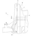
- FIG. It is a side view which shows the toilet device which concerns on Example 1 and 2.
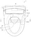
- FIG. It is a top view which shows the toilet device which concerns on Example 1 and 2.
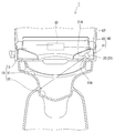
- FIG. 4 is a sectional view taken along line IV-IV in FIG. 3.
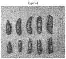
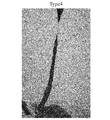
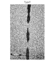
- FIG. It is a schematic diagram for demonstrating the example of a detection by a detection part. It is a figure which shows the example of a stool characteristic pattern (pattern) classification. It is a figure which shows the simulated stool which imitated the stool of the property pattern type (type) 1 which concerns on Example 1 and 2.
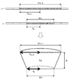
- FIG. 10 is a diagram for explaining a volume determination method by a determination unit according to the second embodiment.
- the toilet device of the present invention may include a display unit that displays a determination result by the determination unit. In this case, the determination result can be easily confirmed.
- the toilet device 1 of Example 1 is a toilet device having a function of determining the properties of excreted stool.
- the toilet device 1 includes a toilet body 10, a detection unit 20, and a determination unit 30, as shown in FIGS.
- the toilet body 10 has a toilet bowl 11 and a reservoir 12.
- the toilet bowl 11 has a mortar-shaped inner surface.
- the reservoir 12 is formed under the toilet bowl 11 and retains the wash water that has circulated through the toilet bowl 11.
- the reservoir 12 is provided below the rear region of the toilet bowl 11.
- a rim 13 is formed at the upper end of the toilet bowl 11.
- a water outlet (not shown) is provided in the toilet bowl 11 below the rim 13.
- the toilet bowl 11 is cleaned on the inner surface through the wash water discharged from the water outlet.
- the wash water that has circulated in the toilet bowl 11 is discharged from a drainage channel (not shown) that continues below the reservoir 12.
- the toilet seat device 40 is placed above the toilet body 10.
- the toilet seat device 40 includes a toilet seat 41, a toilet lid 42, and a toilet seat device main body 43.
- the toilet seat 41 has a substantially oval shape in a plan view and is formed in an annular shape with an inner side opened.
- the toilet seat 41 is disposed above the toilet body 10 along the upper edge of the rim 13 of the toilet body 10.
- a window portion 41 ⁇ / b> A is provided on the lower surface of the toilet seat 41.
- the window portion 41A is formed of a material that transmits infrared rays.
- the toilet lid 42 covers the toilet seat 41 from above, and closes the opening of the toilet seat 41 and the toilet bowl 11 so as to be freely opened and closed.
- the detecting unit 20 detects falling stool excreted in the toilet bowl unit 11 at predetermined time intervals.
- the detection unit 20 has a sensor 21.
- the sensor 21 employs an infrared line sensor.
- the sensor 21 is arranged on the front surface of the light receiving unit 22 in which a plurality of light receiving elements (illustrated as detection elements according to the present invention) are arranged linearly in the horizontal direction.
- a lens 23 a lens 23.
- the sensor 21 is provided with a light emitting unit 24.
- the light emitting unit 24 irradiates infrared rays toward the feces to be detected.
- the light receiving unit 22 and the light emitting unit 24 are arranged on a detection surface 21A which is one surface of the sensor 21 having a rectangular parallelepiped shape. That is, the sensor 21 has directivity in detection sensitivity with respect to the front of the detection surface 21A.
- the sensor 21 is arranged in the toilet seat 41 so as to face the inner side of the toilet bowl 11.
- the sensor 21 detects a falling stool excreted in the toilet bowl 11 through a window 41 ⁇ / b> A provided on the lower surface of the toilet seat 41.
- the sensor 21 of the first embodiment is disposed at a position corresponding to the left side of the rear side of the toilet bowl 11 in a plan view.
- the sensor 21 is arrange
- the detection unit 20 detects falling stool excreted in the toilet bowl unit 11 at predetermined time intervals. That is, the detection unit 20 detects the stool from being excreted to dropping into the water storage unit 12 by a sensor 21 at predetermined time intervals, and acquires data (line data) at each time as a detection result.
- the sensor 21 has 4096 infrared light receiving elements, and can acquire data at a maximum frame rate of 26 kHz (26000 times per second) using a maximum of 4096 infrared light receiving elements.
- the detection unit 20 outputs data including each of the amount of received infrared light (intensity) received by each light receiving element in one frame to the determination unit 30 as one line data.
- the stool property is hardness (softness), and the hardness as the stool property is classified into any of a plurality of property patterns.
- the determination unit 30 extracts feature amounts from the stool line data Ln acquired by the detection unit 20, and compares these feature amounts with the feature amounts extracted in advance for a plurality of stool whose property patterns are known. Thus, it is determined that it is one of the predetermined property patterns.
- the toilet device 1 of the present embodiment includes a display unit 50.
- the display unit 50 displays the determination result by the determination unit 30 and the like.
- the user of the toilet device 1 can confirm the determination result on the display unit 50.
- the display unit 50 can also display convenience improvement advice (advice) based on the determination result by the determination unit 30.
- data transmission from the determination unit 30 to the display unit 50 is not particularly limited, such as wired or wireless.
- a terminal dedicated to this apparatus may be provided like the display unit 50, or a smart phone, a tablet, a PC, or the like may be used as the display unit.
- the determination result data may be directly transmitted to the display unit 50 or may be transferred via another data storage (storage) such as a cloud server.
- past determination result data may be stored so that it can be confirmed at any time.
- the toilet device 1 having such a configuration determines the properties of the stool as follows.
- the falling stool excreted in the toilet bowl 11 by the detection unit 20 is detected at predetermined time intervals.
- the detection unit 20 emits infrared light from the light emitting unit 24 of the sensor 21, and the reflected light is received by the light receiving unit 22.
- the light emitting unit 24 and the light receiving unit 22 are disposed on the detection surface 21 ⁇ / b> A of the sensor 21.
- the sensor 21 is arrange
- the sensor 21 that is an infrared line sensor employs infrared light that is not visible as the light to be detected while the sensor 21 itself is disposed in the toilet seat 41. For this reason, in the toilet device 1, the detection in consideration of privacy is performed without making the user of the toilet device 1 aware that the stool is detected.
- the detection unit 20 outputs the detection result at each time to the determination unit 30 as one line data Ln.
- FIG. 6 schematically shows detection of stool by the detection unit 20. Each two-dimensional image is obtained by photographing falling stool with a camera at predetermined time intervals and arranging them in time series. As shown in FIG. 6, the detection unit 20 detects falling stool at predetermined time intervals. The detection unit 20 acquires line data Ln as a detection result for each hour. The acquired line data Ln is sequentially output to the determination unit 30. The determination unit 30 extracts the feature amount of the stool to be detected based on the entire line data L in one stool, and determines the property of the stool based on the extracted feature amount.
- one defecation is performed from when the detection unit 20 detects the fall of the stool until it is no longer detected.
- stool starts to be detected in the line data Ln + 2, and no stool is detected in the line data Ln + 6. That is, in the case of FIG. 6, the line data Ln + 2 to the line data Ln + 5 are regarded as one bowel movement, and the characteristics of the stool are determined.
- each line data Ln is appropriately subjected to processing for clarifying a region where stool is detected, such as binarization processing and expansion / contraction processing.
- the property of stool in this example is hardness (softness).
- the hardness as a stool property is classified into any of six types of property patterns.
- the determination unit 30 determines that the stool property is one of the predetermined property patterns classified in advance.
- the six types of property patterns are a roll, a ticks, a banana, a semi-kneaded, a mud, and a water.
- types 1 and 2 are defined as stool properties excreted in constipation, types 3 and 4 in health, and types 5 and 6 in diarrhea.
- types 1 to 3 are defined as hard stools and types 4 to 6 as soft stools.
- FIG. 8 to FIG. 14 show simulated stools simulating each type of stool. As shown in these figures, a difference appears in the shape of each type of stool due to the difference in hardness. In this embodiment, when determining the hardness (softness) of the stool, attention is paid to the shape of the stool, and the feature quantity related to the shape is extracted.
- FIG. 15 schematically shows an example of line data Ln acquired by detecting stool.
- each line data Ln is shown as a two-dimensional image by arranging them in time series.
- the run length The feature amount is extracted based on the data digitized by performing processing such as (run length) encoding.
- the acquired line data Ln is erased when the determination by the determination unit 30 is performed. As described above, in this embodiment, privacy is also taken into account in handling the acquired data.
- the number of labels is a feature quantity that serves as an index representing the surface irregularities of the stool.
- the stool of the type 2 property is characterized by having more irregularities on the surface than the stool of other properties (see FIG. 9 and the like).
- region by reflection will appear widely disperse
- one line data Ln is acquired, and this line data Ln is subjected to an 8-connected labeling process on the previous line data Ln-1.
- searching in the opposite direction from the other end to the one end is performed again.
- the labeling processing method is not limited to this, and various methods such as a method using a look-up table can be appropriately selected and employed.
- the determination unit 30 determines the characteristics of the stool based on these feature values. Specifically, the extracted feature amount is projected onto the feature amount space.
- This feature amount space is a space in which each feature is a vector.
- areas corresponding to the type 1 to type 6 characteristic patterns are determined in advance based on the feature amounts extracted for a plurality of stools whose characteristic patterns are known. For this reason, it is possible to determine that the property pattern corresponding to the projected feature amount space region is the stool property to be detected.
- each feature amount space is divided more clearly.
- the detection unit 20 includes the sensor 21 in which the light receiving elements as detection elements are linearly arranged in the horizontal direction. And the determination part 30 determines the property of a stool using the line data Ln which is the detection result detected by such a detection part 20. FIG.
- the toilet device 1 can determine the properties of the stool without acquiring a two-dimensional image of the stool with a camera or the like. For this reason, a user's sense of resistance can be reduced.
- the toilet device 1 can detect a stool while considering the privacy of the user.
- the determination unit 30 can extract the feature amount of the stool to be detected from the line data Ln as the detection result, and determine at least one of the property or volume of the stool based on the feature amount. In this case, since the characteristic / volume of the stool is determined from the characteristic amount of the stool, the user's sense of resistance can be reduced.
- the toilet device 1 includes a display unit 50 that displays a determination result by the determination unit 30. Thereby, the user can confirm the determination result easily.
- Example 2 a toilet apparatus according to Example 2 will be described with reference to FIG.
- the toilet apparatus according to the second embodiment is different from the first embodiment in that the determination target by the determination unit is the volume of stool.
- the toilet device In the determination of the volume of the stool, the toilet device according to the second embodiment first detects the falling stool excreted in the toilet bowl 11 by the detection unit at predetermined time intervals, as in the first embodiment. As shown in FIG. 17, in the second embodiment, the stool width Wn indicating the stool region in the acquired line data Ln is extracted as the feature amount. The determination unit calculates the volume Vn of the truncated cone having the horizontal width Wn and the horizontal width Wn-1 in the previous line data Ln-1 as the diameters at both ends and the height as h. Then, the volume Vn is calculated for all the line data Ln, and the volume of the stool is determined by integrating them. Note that the height h of each truncated cone is a stool fall height per time interval and is substantially constant.
- the toilet device according to the second embodiment easily achieves the volume of the stool in addition to the same effect as the first embodiment in which stool can be detected while considering the privacy of the user. Can be determined.
- the mode including the display unit is illustrated, but this is not essential. Moreover, when a display part is provided, a display part is not restricted to the form of the said Example, Another form may be sufficient.
- the sensor is arranged on the left rear side, but this is not essential. You may arrange
- the sensor is disposed on the lower surface of the toilet seat or the like, but this is not essential.
- the senor may be disposed on an inner peripheral surface of a toilet seat or the like, or may be disposed on a portion other than the toilet seat.
- the form of extracting three types of feature quantities is illustrated as the feature quantity, but two or less kinds or four or more kinds of feature quantities may be extracted.
- the form in which the stool property pattern is determined using all of the extracted three types of feature values is exemplified. For example, only some types of extracted feature values are used. The determination used may be performed.
- a multi-stage determination may be performed, for example, by determining in advance only whether or not the pattern is a specific property pattern by using a part of feature amount that clearly indicates the characteristics of the specific property pattern. .
- the form in which one of the stool properties or the volume is determined is illustrated, but the form in which both the stool characteristics and the volume are determined may be used.
- the example in which the detection unit and the determination unit are provided in the toilet device that is, the example of the toilet device according to the present invention has been described. May be provided.
- other configurations such as the detection unit, the determination unit, and the sensor in the above description can also be applied as the configuration of the toilet seat device according to the present invention.
Landscapes
- Health & Medical Sciences (AREA)
- Life Sciences & Earth Sciences (AREA)
- Chemical & Material Sciences (AREA)
- Engineering & Computer Science (AREA)
- Public Health (AREA)
- Biochemistry (AREA)
- General Physics & Mathematics (AREA)
- Pathology (AREA)
- Immunology (AREA)
- General Health & Medical Sciences (AREA)
- Physics & Mathematics (AREA)
- Analytical Chemistry (AREA)
- Biomedical Technology (AREA)
- Medicinal Chemistry (AREA)
- Urology & Nephrology (AREA)
- Food Science & Technology (AREA)
- Molecular Biology (AREA)
- Epidemiology (AREA)
- Hematology (AREA)
- Hydrology & Water Resources (AREA)
- Water Supply & Treatment (AREA)
- Bidet-Like Cleaning Device And Other Flush Toilet Accessories (AREA)
- Toilet Supplies (AREA)
- Investigating Or Analysing Biological Materials (AREA)
- Measuring And Recording Apparatus For Diagnosis (AREA)
Abstract
プライバシーに配慮しつつ大便の検知を行うことができる便器装置及び便座装置を提供する。 便器装置(1)は、便鉢部(11)及び便鉢部(11)の下方に連なる溜水部(12)を有する便器本体(10)と、複数の受光素子(検出素子)が直線状に配置されたセンサ(21)を有し、便鉢部(11)内に排泄された落下中の大便を所定の時間間隔で検知する検知部(20)と、検知部(20)により検知したラインデータ(検知結果)から大便の性状を判定する判定部(30)と、を備える。
Description
本発明は、便器装置、及び便座装置に関するものである。
人体等の生体の排泄物には、その生体の健康状態が反映される。特に、大便には、消化器系の健康状態(腸内環境)が反映される。したがって、大便の性状を把握することは、腸内環境の把握に役立てられる。このため、カメラ(camera)で大便を撮影し、その性状を推定することが従来行われている(例えば、特許文献1参照)。
特許文献1の装置は、生体データ(data)を取得して健康状態を推定する。この装置は、画像撮影部と、データ解析部と、を備えている。画像撮影部は、トイレ(toilet)の便器に設けられ、生体の排泄物を撮影する。データ解析部は、画像撮影部による撮影画像を解析する。また、データ解析部は、撮影画像の解析により排泄物の性状に関する生体データを取得し、この取得した生体データから生体の健康状態を推定する。
特許文献1の装置では、排泄物のデータを取得するに当たり、排泄物の画像を撮影する。この場合、排泄物が撮影されることに対して使用者が抵抗感を覚えてしまうおそれがあった。また、撮影した画像に使用者の局部等の身体が写り込んでしまうおそれがあることなども抵抗感を覚える一因となり得る。
本発明は、上記従来の実情に鑑みてなされたものであって、使用者のプライバシー(privacy)に配慮しつつ大便の検知を行うことができる便器装置、及び便座装置を提供することを解決すべき課題としている。
本発明の便器装置は、便鉢部及び前記便鉢部の下方に連なる溜水部を有する便器本体と、
複数の検出素子が直線状に配置されたセンサ(sensor)を有し、前記便鉢部内に排泄された落下中の大便を所定の時間間隔で検知する検知部と、
前記検知部により検知した検知結果から大便の性状又は体積の少なくとも一方を判定する判定部と、を備えることを特徴とする。
複数の検出素子が直線状に配置されたセンサ(sensor)を有し、前記便鉢部内に排泄された落下中の大便を所定の時間間隔で検知する検知部と、
前記検知部により検知した検知結果から大便の性状又は体積の少なくとも一方を判定する判定部と、を備えることを特徴とする。
この便器装置は、検知部が、検出素子が直線状に配置されたセンサを有している。そして、判定部は、このような検知部により検知した検知結果を用いて大便の性状又は体積の少なくとも一方を判定する。このように、本発明の便器装置は、カメラ等により大便の2次元画像を取得することなく大便の性状や体積を判定することができる。このため、使用者の抵抗感を軽減することができる。
したがって、本発明の便器装置は、使用者のプライバシーに配慮しつつ大便の検知を行うことができる。
本発明の便座装置は、便鉢部及び前記便鉢部の下方に連なる溜水部を有する便器本体の上方に配置される便座装置であって、
便鉢部及び前記便鉢部の下方に連なる溜水部を有する便器本体と、
複数の検出素子が直線状に配置されたセンサを有し、前記便鉢部内に排泄された落下中の大便を所定の時間間隔で検知する検知部と、
前記検知部により検知した検知結果から大便の性状又は体積の少なくとも一方を判定する判定部と、を備えることを特徴とする。
便鉢部及び前記便鉢部の下方に連なる溜水部を有する便器本体と、
複数の検出素子が直線状に配置されたセンサを有し、前記便鉢部内に排泄された落下中の大便を所定の時間間隔で検知する検知部と、
前記検知部により検知した検知結果から大便の性状又は体積の少なくとも一方を判定する判定部と、を備えることを特徴とする。
この便座装置は、検知部が、検出素子が直線状に配置されたセンサを有している。そして、判定部は、このような検知部により検知した検知結果を用いて大便の性状又は体積の少なくとも一方を判定する。このように、本発明の便座装置は、カメラ等により大便の2次元画像を取得することなく大便の性状や体積を判定することができる。このため、使用者の抵抗感を軽減することができる。
したがって、本発明の便座装置は、使用者のプライバシーに配慮しつつ大便の検知を行うことができる。
本発明における好ましい実施の形態を説明する。
本発明の便器装置において、前記判定部は、前記検知結果から検知対象の大便の特徴量を抽出し、前記特徴量に基づいて大便の性状又は体積の少なくとも一方を判定し得る。この場合、大便の特徴量から大便の性状・体積を判定するので、使用者の抵抗感を軽減することができる。
本発明の便器装置は、前記判定部による判定結果を表示する表示部を備え得る。この場合、判定結果を容易に確認することができる。
次に、本発明の便器装置を具体化した実施例について、図面を参照しつつ説明する。なお、以下の説明において、前後方向、左右方向、上下方向とは、便器に着座した状態の使用者から見た前後方向、左右方向、上下方向を夫々示すものとする。
<実施例1>
実施例1の便器装置1は、排泄された大便の性状を判定する機能を有する便器装置である。この便器装置1は、図1~図4に示すように、便器本体10、検知部20、及び判定部30を備えている。
実施例1の便器装置1は、排泄された大便の性状を判定する機能を有する便器装置である。この便器装置1は、図1~図4に示すように、便器本体10、検知部20、及び判定部30を備えている。
便器本体10は便鉢部11及び溜水部12を有している。便鉢部11はすり鉢状の内面を有して形成されている。溜水部12は便鉢部11の下方に連なって形成され、便鉢部11内を流通した洗浄水を滞留させる。溜水部12は、便鉢部11の後方領域の下方に設けられている。便鉢部11の上端にはリム(rim)13が形成されている。リム13の下方の便鉢部11内には図示しない吐水口が設けられている。便鉢部11は吐水口から吐出される洗浄水が流通して内面を洗浄される。便鉢部11内を流通した洗浄水は、溜水部12の下方に連なる排水路(図示せず)から排出される。
便器本体10の上方には便座装置40が載置されている。便座装置40は、便座41、便蓋42及び便座装置本体43を有している。図3に示すように、便座41は、平面視において略楕円形状をなしているとともに、その内側が開口した環状に形成されている。便座41は、便器本体10のリム13の上縁部に沿うように便器本体10の上方に配置されている。便座41の下面には窓部41Aが設けられている。窓部41Aは赤外線を透過する材質で形成されている。便蓋42は、便座41を上方から覆い、便座41及び便鉢部11の開口を開閉自在に閉塞する。便座装置本体43は、便鉢部11の後方に配置されており、便器本体10に着脱自在に固定されている。便座装置本体43は、便座41及び便蓋42を回動自在に軸支するとともに、その内部に局部洗浄装置等の機能部品や判定部30等を収納している。
検知部20は、便鉢部11内に排泄された落下中の大便を所定の時間間隔で検知する。検知部20はセンサ21を有している。本実施例において、センサ21は赤外線ライン(line)センサを採用している。図5に示すように、センサ21は、複数の受光素子(本発明に係る検出素子として例示する)を水平方向に直線状に配列した受光部22と、この受光部22の前面に配されたレンズ(lens)23とを有している。また、センサ21には発光部24が設けられている。発光部24は、検知の対象となる便に向かって赤外線を照射する。これら受光部22及び発光部24は、直方体形状をなすセンサ21の一面である検出面21Aに配されている。すなわち、センサ21は、検出面21Aの前方に対する検出感度に指向性を有している。
センサ21は、図4に示すように、便座41内に便鉢部11の内側方向を向いて配置されている。センサ21は、便座41の下面に設けられた窓部41Aを介して、便鉢部11内に排泄された落下中の大便を検知する。図3及び図4に示すように、本実施例1のセンサ21は、平面視における便鉢部11の後部側左方に対応する位置に配置されている。また、センサ21は、その検知方向を斜め下方として配置されている。センサ21は、溜水部12の上方を検知範囲として、落下中、すなわち、体外に放出されてから溜水部12の水面に到達するまでの排泄物を検知する。
検知部20は、便鉢部11内に排泄された落下中の便を所定の時間間隔で検知する。すなわち、検知部20は、排泄されてから溜水部12に落下するまでの便について所定の時間間隔でセンサ21により検知し、各時間におけるデータ(ラインデータ)を検知結果として取得する。センサ21は、4096個の赤外線受光素子を有するとともに、最大4096個の赤外線受光素子を用いて、最大26kHz(毎秒26000回)のフレームレート(frame rate)でデータを取得することができる。検知部20は、1フレームにおいて各受光素子が受光した赤外線の受光量(強度)の夫々を含んだデータを1つのラインデータとして判定部30に出力する。
判定部30は、検知部20により検知した検知結果であるラインデータLnに基づいて、大便の性状の判定を行う。具体的には、判定部30は、得られたラインデータLnから検知対象の大便の特徴量を抽出する。抽出する特徴量とは、具体的には、各ラインデータLnにおける大便に相当する画素の数、大便が検知されたフレームの数、1つの便領域内に存在する高輝度領域の数等である。これらの特徴量は、大便の横幅(直径)、長さ、表面の凹凸の多さを夫々表す指標となる。そして、判定部30は、これらの特徴量に基づいて大便の性状の判定を行う。
なお、本実施例において、大便の性状とは硬さ(軟らかさ)であり、この大便の性状としての硬さを複数に大別された性状パターンのいずれかに分類する。具体的には、判定部30は、検知部20により取得した大便のラインデータLnから特徴量を抽出し、これらの特徴量を性状パターンが既知の複数の大便について予め抽出した特徴量と比較することにより、所定の性状パターンのうちの1つであると判定する。
また、本実施例の便器装置1は表示部50を備えている。表示部50は判定部30による判定結果等を表示する。本便器装置1の使用者は、この表示部50により判定結果を確認することができる。また、本実施例では、表示部50には、判定部30による判定結果に基づいた便性改善アドバイス(advice)も表示することができる。
なお、判定部30から表示部50へのデータの送信は、有線、無線等特に問わない。また、表示部50のように本装置専用の端末を設けるようにしてもよいし、スマートフォン(smart phone)、タブレット(tablet)、PC等を表示部として利用してもよい。また、判定結果データは、表示部50に直接送信するようにしてもよいし、クラウドサーバー(cloud server)等の他のデータストレージ(storage)を介して転送するようにしてもよい。更に、過去の判定結果データを記憶させるようにして、随時確認できるようにしてもよい。
このような構成を有する便器装置1は、次に示すようにして大便の性状を判定する。
大便の性状を判定するにあたっては、最初に、検知部20により便鉢部11内に排泄された落下中の大便を所定の時間間隔で検知する。検知部20は、センサ21の発光部24から赤外線を照射し、受光部22によりその反射光を受光する。これら発光部24及び受光部22はセンサ21の検出面21Aに配されている。そして、センサ21は検出面21Aを便鉢部11内の後方領域に向けて配置されており、大便を精度良く検知する。また、赤外線ラインセンサであるセンサ21は、センサ21自体が便座41内に配されているとともに、検出対象の光として視認不能な赤外線を採用している。このため、便器装置1では、大便が検知されていることを便器装置1の使用者に意識させることなく、プライバシーに配慮した検知が行われる。
検知部20は、各時間における検知結果を1つのラインデータLnとして判定部30に出力する。図6は、検知部20による大便の検知を模式的に示している。なお、各2次元画像は、落下する大便をカメラにより所定の時間間隔で撮影して時系列に並べたものである。図6に示すように、検知部20は、落下する大便を所定の時間間隔で検知する。検知部20は、時間毎の検知結果としてラインデータLnを取得する。取得されたラインデータLnは順次判定部30に出力される。判定部30は、1回の排便における全ラインデータLに基づいて、検知対象の大便の特徴量を抽出するとともに、抽出した特徴量に基づいて大便の性状を判定する。
なお、本実施例では、検知部20により大便の落下が検知されてから検知されなくなるまでを1回の排便としている。図6の場合、ラインデータLn+2において大便が検知され始め、ラインデータLn+6では大便が検知されていない。すなわち、図6の場合には、ラインデータLn+2からラインデータLn+5までを1回の排便とし、これについての大便の性状を判定する。また、各ラインデータLnには2値化処理、膨張・収縮処理等、大便を検知した領域を明確にする処理を適宜施している。
本実施例における大便の性状とは、硬さ(軟らかさ)である。本実施例の場合、大便の性状としての硬さを6タイプに大別された性状パターンのいずれかに分類する。すなわち、判定部30は、大便の性状を、予め複数に分類された所定の性状パターンのうちの1つであると判定する。
6タイプの性状パターンとは、図7に示すように、コロコロ、カチカチ俵、バナナ、半練り、泥状、水状である。なお、これらの性状のうち、タイプ1及びタイプ2は便秘、タイプ3及び4は健康、タイプ5及び6は下痢の各状態において排泄される大便の性状と定義している。また、上記性状のうち、タイプ1~3は硬便、タイプ4~6は軟便と定義している。図8~図14は、各タイプの大便を模した模擬便を夫々示している。これらの図に示すように、硬さの違いによって各タイプの大便では形状に差が現れている。本実施例では、大便の硬さ(軟らかさ)を判定するに当たり大便の形状に注目し、形状に関連する特徴量を抽出する。
具体的には、本実施例では、特徴量として、(1)連続スキャン(scan)ライン数、(2)平均横幅、及び(3)ラベル(label)数という3つの特徴量をラインデータLnから取得する。これらの特徴量の抽出について、図15を参照して説明する。図15は大便を検知して取得したラインデータLnの例を模式的に示したものである。なお、図15では、便宜上、各ラインデータLnを時系列に並べたことにより2次元像のように示されているが、本実施例の場合には、ラインデータLnの取得毎にランレングス(run length)符号化等の処理を施して数値化したデータに基づいて特徴量の抽出を行っている。また、本実施例において、取得したラインデータLnは、判定部30による判定を行った時点で消去される。これらのように、本実施例では、取得データの取扱いに関してもプライバシーに配慮したものとしている。
(1)の連続スキャンライン数とは、大便が検知されてから検知され終わるまでのラインデータLnの数である。この連続スキャンライン数は大便の長さを表す指標となる。例えば、図15の場合、ラインデータL2からL10まで大便が検知されている。したがって、図15における連続スキャンライン数は9である。(2)の平均横幅とは、大便が検知されてから検知され終わるまでの各ラインデータLnにおける大便の検知された領域の幅の平均であり、大便の横幅を表す指標となる。例えば、図15の場合、L2の大便の検知された領域の幅は3、L3は8、L4は12、・・・となっている。したがって、これらを平均した値9.33が図15における各ラインデータLnの平均横幅となる。
(3)のラベル数とは、大便の表面の凹凸を表す指標となる特徴量である。例えば、タイプ2の性状の大便は、他の性状の大便と比較してその表面に凹凸が多く生じていることが特徴的である(図9等参照)。そして、このような凹凸が多く生じている場合、大便の表面に光を照射すると、反射による高輝度の領域が広く分散して表われる。したがって、本実施例の場合には、検知部20から照射された赤外線が凹凸に応じて反射し、大便を示す検出強度よりも高い強度の領域が表われる。ラベル数の抽出とは、このような高強度領域に対してラベリング(labeling)処理を行うことによりその数がいくつ付与されたかを算出したものである。図15において、有色のマスは大便を示す領域を表しており、この大便領域中の白抜きマスが赤外線の検出強度が高い領域を表している。したがって、図15に示すラインデータLnから抽出されるラベル数は2である。
なお、本実施例の場合、ラベリング処理として、1つのラインデータLnを取得し、このラインデータLnを1つ前のラインデータLn-1に対して8連結のラベリング処理を行っている。また、本実施例では、ラインデータLnの一端から他端に向かっての探索を行った後、他端から一端への反対方向への探索を再度行っている。ラベリング処理の手法についてはこれに限定されず、ルックアップテーブル(lookup table)を用いた手法など、種々の手法を適宜選択して採用することができる。
上述のようにしてラインデータLnから特徴量を抽出した後、判定部30は、これらの特徴量に基づいて大便の性状の判定を行う。具体的には、抽出した特徴量を、特徴量空間に投影する。この特徴量空間は、各特徴をベクトル(vector)とする空間である。また、この空間は、性状パターンが既知の複数の大便について抽出した特徴量に基づいて、タイプ1~6の性状パターンに対応する領域が予め定められている。このため、投影された特徴量空間の領域に対応する性状パターンを検知対象の大便の性状であると判定することができる。
なお、上記の特徴量空間の領域を各性状パターンに対応するように分割する際には、例えば、サポートベクターマシン(Support Vector Machine, SVM)等のパターン認識手法を用いて、特徴量空間の各性状パターンに対応する領域がより明瞭に分割されるようにしておくことが好ましい。
また、判定部30による判定結果は表示部50に表示される。便器装置1の使用者は、この表示部50により判定結果を確認することができる。表示部50では、直近の判定結果のみならず、過去の判定結果を呼び出して表示したり、判定結果の時系列変化を表示したりすることができる。また、表示部50には、判定部30による判定結果に基づいた便性改善アドバイスを表示することもできる。
以上より、実施例1の便器装置1は、便器本体10、検知部20、及び判定部30を備えている。便器本体10は、便鉢部11及び便鉢部11の下方に連なる溜水部12を有している。検知部20は便鉢部11内に排泄された落下中の大便を所定の時間間隔で検知する。また、検知部20はセンサ21を有している。センサ21は複数の受光素子が水平方向に直線状に配置されている。判定部30は、検知部20により検知した検知結果としてのラインデータLnから、大便の性状を判定する。
このように、便器装置1は、検知部20が、検出素子としての受光素子が水平方向に直線状に配置されたセンサ21を有している。そして、判定部30は、このような検知部20により検知した検知結果であるラインデータLnを用いて大便の性状を判定する。このように、便器装置1は、カメラ等により大便の2次元画像を取得することなく大便の性状を判定することができる。このため、使用者の抵抗感を軽減することができる。
したがって、便器装置1は、使用者のプライバシーに配慮しつつ大便の検知を行うことができる。
また、判定部30は、検知結果としてのラインデータLnから検知対象の大便の特徴量を抽出し、前記特徴量に基づいて大便の性状又は体積の少なくとも一方を判定し得る。この場合、大便の特徴量から大便の性状・体積を判定するので、使用者の抵抗感を軽減することができる。
また、便器装置1は、判定部30による判定結果を表示する表示部50を備えている。これにより、使用者は判定結果を容易に確認することができる。
<実施例2>
次に、実施例2に係る便器装置について、図16等を参照しつつ説明する。実施例2の便器装置は、判定部による判定の対象を大便の体積としている点において実施例1とは異なる。
次に、実施例2に係る便器装置について、図16等を参照しつつ説明する。実施例2の便器装置は、判定部による判定の対象を大便の体積としている点において実施例1とは異なる。
大便の体積の判定において、実施例2の便器装置は、実施例1と同様に、まず、検知部により便鉢部11内に排泄された落下中の大便を所定の時間間隔で検知する。図17に示すように、実施例2では、特徴量として、取得したラインデータLnにおける大便の領域を示す大便の横幅Wnを抽出する。判定部は、この横幅Wnと、1つ前のラインデータLn-1における横幅Wn-1を両端の直径とするとともに、高さをhとする円錐台の体積Vnを算出する。そして、全てのラインデータLnについて体積Vnの算出を行い、それらを積算することにより大便の体積を判定する。なお、各円錐台の高さhは、時間間隔当たりの大便の落下高さであり略一定である。
このように、実施例2の便器装置は、使用者のプライバシーに配慮しつつ大便の検知を行うことができるという実施例1と同様の作用効果を奏することに加えて、大便の体積を容易に判定することができる。
本発明は上記記述及び図面によって説明した実施例に限定されるものではなく、例えば次のような実施形態も本発明の技術的範囲に含まれる。
(1)実施例1及び2では、センサとして、4096個の赤外線受光素子を有するとともに、最大4096個の赤外線受光素子を用いて、最大26kHz(毎秒26000回)のフレームレートでデータを取得することができる赤外線ラインセンサを利用したが、受光素子の数や受光素子の配列方向、フレームレート等はこれに限定されるものではない。また、センサとしては、検出対象となる光線を赤外線に限らず、可視光線や他の不可視光線であってもよい。
(2)実施例1及び2では、表示部を備える形態を例示したが、これは必須ではない。また、表示部を備える場合、表示部は上記実施例の形態に限らず、他の形態であってもよい。
(3)実施例1及び2では、センサを左後方に配置する形態を例示したが、これは必須ではない。センサは、右後方など、他の位置に配置してもよい。なお、図3の2点鎖線で囲んだ領域は、大便を検知するセンサの配置に好ましい領域である。
(4)実施例1及び2では、センサを便座等の下面に配置する形態を例示したが、これは必須ではない。センサは、例えば、便座等の内周面に配置してもよく、また、便座以外の部位に配置してもよい。
(5)実施例1及び2では、特徴量として、3種類の特徴量を抽出する形態を例示したが、2種類以下又は4種類以上の特徴量を抽出する形態であってもよい。
(6)実施例1及び2では、抽出した3種類の特徴量の全ての種類を用いて大便の性状パターンを判定する形態を例示したが、例えば、抽出した特徴量の一部の種類のみを用いた判定を行ってもよい。さらに、例えば、特定の性状パターンの特徴をよく示す一部の特徴量を用いて、その特定性状パターンであるか否かについてのみ予め判定を行うなど、多段階の判定を行うようにしてもよい。
(7)実施例1及び2では、大便の性状又は体積の一方を判定する形態を例示したが、大便の性状及び体積の両方を判定する形態であってもよい。
(8)実施例1及び2では、検知部及び判定部が便器装置に備えられている例、すなわち、本発明に係る便器装置の例を説明したが、これら検知部及び判定部は、便座装置に備えられていてもよい。また、他の上記説明における検知部や判定部、センサ等、その他の構成については、本発明に係る便座装置の構成としても適用可能である。
(1)実施例1及び2では、センサとして、4096個の赤外線受光素子を有するとともに、最大4096個の赤外線受光素子を用いて、最大26kHz(毎秒26000回)のフレームレートでデータを取得することができる赤外線ラインセンサを利用したが、受光素子の数や受光素子の配列方向、フレームレート等はこれに限定されるものではない。また、センサとしては、検出対象となる光線を赤外線に限らず、可視光線や他の不可視光線であってもよい。
(2)実施例1及び2では、表示部を備える形態を例示したが、これは必須ではない。また、表示部を備える場合、表示部は上記実施例の形態に限らず、他の形態であってもよい。
(3)実施例1及び2では、センサを左後方に配置する形態を例示したが、これは必須ではない。センサは、右後方など、他の位置に配置してもよい。なお、図3の2点鎖線で囲んだ領域は、大便を検知するセンサの配置に好ましい領域である。
(4)実施例1及び2では、センサを便座等の下面に配置する形態を例示したが、これは必須ではない。センサは、例えば、便座等の内周面に配置してもよく、また、便座以外の部位に配置してもよい。
(5)実施例1及び2では、特徴量として、3種類の特徴量を抽出する形態を例示したが、2種類以下又は4種類以上の特徴量を抽出する形態であってもよい。
(6)実施例1及び2では、抽出した3種類の特徴量の全ての種類を用いて大便の性状パターンを判定する形態を例示したが、例えば、抽出した特徴量の一部の種類のみを用いた判定を行ってもよい。さらに、例えば、特定の性状パターンの特徴をよく示す一部の特徴量を用いて、その特定性状パターンであるか否かについてのみ予め判定を行うなど、多段階の判定を行うようにしてもよい。
(7)実施例1及び2では、大便の性状又は体積の一方を判定する形態を例示したが、大便の性状及び体積の両方を判定する形態であってもよい。
(8)実施例1及び2では、検知部及び判定部が便器装置に備えられている例、すなわち、本発明に係る便器装置の例を説明したが、これら検知部及び判定部は、便座装置に備えられていてもよい。また、他の上記説明における検知部や判定部、センサ等、その他の構成については、本発明に係る便座装置の構成としても適用可能である。
1…便器装置
10…便器本体
11…便鉢部
12…溜水部
13…リム
20…検知部
21…センサ
21A…検出面
22…受光部
23…レンズ
24…発光部
30…判定部
40…便座装置
41…便座
41A…窓部
42…便蓋
43…便座装置本体
50…表示部
Ln…ラインデータ
Vn…ラインデータ毎に判定される大便の体積
Wn…大便を示す領域の横幅
10…便器本体
11…便鉢部
12…溜水部
13…リム
20…検知部
21…センサ
21A…検出面
22…受光部
23…レンズ
24…発光部
30…判定部
40…便座装置
41…便座
41A…窓部
42…便蓋
43…便座装置本体
50…表示部
Ln…ラインデータ
Vn…ラインデータ毎に判定される大便の体積
Wn…大便を示す領域の横幅
Claims (4)
- 便鉢部及び前記便鉢部の下方に連なる溜水部を有する便器本体と、
複数の検出素子が直線状に配置されたセンサを有し、前記便鉢部内に排泄された落下中の大便を所定の時間間隔で検知する検知部と、
前記検知部により検知した検知結果から大便の性状又は体積の少なくとも一方を判定する判定部と、を備えることを特徴とする便器装置。 - 前記判定部は、前記検知結果から検知対象の大便の特徴量を抽出し、前記特徴量に基づいて大便の性状又は体積の少なくとも一方を判定することを特徴とする請求項1記載の便器装置。
- 前記判定部による判定結果を表示する表示部を備えていることを特徴とする請求項1又は2記載の便器装置。
- 便鉢部及び前記便鉢部の下方に連なる溜水部を有する便器本体の上方に配置される便座装置であって、
複数の検出素子が直線状に配置されたセンサを有し、前記便鉢部内に排泄された落下中の大便を所定の時間間隔で検知する検知部と、
前記検知部により検知した検知結果から大便の性状又は体積の少なくとも一方を判定する判定部と、を備えることを特徴とする便座装置。
Applications Claiming Priority (2)
| Application Number | Priority Date | Filing Date | Title |
|---|---|---|---|
| JP2017038080A JP6894722B2 (ja) | 2017-03-01 | 2017-03-01 | 便器装置、及び便座装置 |
| JP2017-038080 | 2017-03-01 |
Publications (1)
| Publication Number | Publication Date |
|---|---|
| WO2018159369A1 true WO2018159369A1 (ja) | 2018-09-07 |
Family
ID=63370129
Family Applications (1)
| Application Number | Title | Priority Date | Filing Date |
|---|---|---|---|
| PCT/JP2018/005825 Ceased WO2018159369A1 (ja) | 2017-03-01 | 2018-02-20 | 便器装置、及び便座装置 |
Country Status (2)
| Country | Link |
|---|---|
| JP (2) | JP6894722B2 (ja) |
| WO (1) | WO2018159369A1 (ja) |
Cited By (5)
| Publication number | Priority date | Publication date | Assignee | Title |
|---|---|---|---|---|
| WO2021060174A1 (ja) * | 2019-09-24 | 2021-04-01 | 株式会社Lixil | 判定装置 |
| CN112771371A (zh) * | 2019-08-30 | 2021-05-07 | Toto株式会社 | 便座装置以及排泄物感测装置 |
| CN112771233A (zh) * | 2019-08-30 | 2021-05-07 | Toto株式会社 | 便座装置以及排泄物感测装置 |
| CN113450911A (zh) * | 2020-03-26 | 2021-09-28 | 松下家电(中国)有限公司 | 便秘分析方法、装置及计算机设备 |
| JP2022147113A (ja) * | 2021-03-23 | 2022-10-06 | Toto株式会社 | 排泄情報管理システム |
Families Citing this family (20)
| Publication number | Priority date | Publication date | Assignee | Title |
|---|---|---|---|---|
| JP6816799B1 (ja) * | 2019-08-30 | 2021-01-20 | Toto株式会社 | 便座装置及び排泄物検知装置 |
| JP6777207B1 (ja) * | 2019-08-30 | 2020-10-28 | Toto株式会社 | 便座装置及び排泄物検知装置 |
| US12516514B2 (en) | 2019-08-30 | 2026-01-06 | Toto Ltd. | Defecation recording system, defecation recording method and defecation recording program |
| JP6881526B2 (ja) * | 2019-08-30 | 2021-06-02 | Toto株式会社 | 便座装置及び排泄物検知装置 |
| WO2021040019A1 (ja) * | 2019-08-30 | 2021-03-04 | Toto株式会社 | 便座装置及び排泄物検知装置 |
| JP6777206B1 (ja) * | 2019-08-30 | 2020-10-28 | Toto株式会社 | 便座装置及び排泄物検知装置 |
| JP2021038637A (ja) * | 2019-08-30 | 2021-03-11 | Toto株式会社 | 便座装置及び排泄物検知装置 |
| US11802830B2 (en) | 2019-08-30 | 2023-10-31 | Toto Ltd. | Toilet seat apparatus and excrement detection apparatus |
| JP7581643B2 (ja) * | 2020-03-31 | 2024-11-13 | Toto株式会社 | 便座装置及び大便器装置 |
| JP7287366B2 (ja) * | 2020-04-03 | 2023-06-06 | Toto株式会社 | 排泄物管理システム、排泄情報管理方法、プログラム、エッジサーバ及び便座装置 |
| CN113785554A (zh) * | 2020-04-03 | 2021-12-10 | Toto株式会社 | 排泄物管理系统、排泄信息管理方法、程序、边缘服务器以及便座装置 |
| WO2021261128A1 (ja) * | 2020-06-26 | 2021-12-30 | パナソニック株式会社 | 出力装置、方法、及びプログラム |
| JP7591725B2 (ja) * | 2020-09-04 | 2024-11-29 | パナソニックIpマネジメント株式会社 | 便器装置 |
| JP7507348B2 (ja) * | 2020-10-29 | 2024-06-28 | パナソニックIpマネジメント株式会社 | 便状態表示システムおよびそれを作動させるためのプログラム |
| JP6945172B1 (ja) * | 2020-12-22 | 2021-10-06 | パナソニックIpマネジメント株式会社 | 便器装置 |
| JP7160128B2 (ja) * | 2021-03-23 | 2022-10-25 | Toto株式会社 | 情報処理システム |
| CN117940047A (zh) | 2021-09-28 | 2024-04-26 | Toto株式会社 | 便座装置以及大便器装置 |
| JP7835050B2 (ja) * | 2022-02-28 | 2026-03-25 | Toto株式会社 | 便座装置及び便器装置 |
| JP7435646B2 (ja) * | 2022-03-01 | 2024-02-21 | Toto株式会社 | トイレ装置 |
| JP2023143245A (ja) * | 2022-03-25 | 2023-10-06 | Toto株式会社 | 便座装置及び便器装置 |
Citations (8)
| Publication number | Priority date | Publication date | Assignee | Title |
|---|---|---|---|---|
| JPH06201611A (ja) * | 1993-01-08 | 1994-07-22 | Datsuku Eng Kk | シート状印刷物の欠陥検出方法 |
| JP2006262956A (ja) * | 2005-03-22 | 2006-10-05 | Aruze Corp | 遊技機及びメダル選別装置 |
| JP2008054835A (ja) * | 2006-08-30 | 2008-03-13 | Toshiba Corp | 健康状態診断システム |
| JP2009229315A (ja) * | 2008-03-24 | 2009-10-08 | Toto Ltd | 排泄物性状測定装置 |
| WO2015083505A1 (ja) * | 2013-12-03 | 2015-06-11 | 株式会社イシダ | 近赤外線検査装置 |
| JP2016004005A (ja) * | 2014-06-18 | 2016-01-12 | 関根 弘一 | 大便色検知装置 |
| WO2016060329A1 (ko) * | 2014-10-13 | 2016-04-21 | 한국생산기술연구원 | 배설물형상측정장치 및 방법 |
| WO2016063547A1 (ja) * | 2014-10-24 | 2016-04-28 | 日本電気株式会社 | 排泄物の分析装置、該分析装置を備えた便器および排泄物の分析方法 |
Family Cites Families (3)
| Publication number | Priority date | Publication date | Assignee | Title |
|---|---|---|---|---|
| JP2007252805A (ja) * | 2006-03-24 | 2007-10-04 | Konica Minolta Holdings Inc | データ検出装置及びデータ検出方法 |
| JP5875878B2 (ja) * | 2012-01-25 | 2016-03-02 | 株式会社イシダ | 密度算出装置 |
| JP6747656B2 (ja) * | 2014-02-28 | 2020-08-26 | 国立大学法人富山大学 | 排泄管理システム |
-
2017
- 2017-03-01 JP JP2017038080A patent/JP6894722B2/ja active Active
-
2018
- 2018-02-20 WO PCT/JP2018/005825 patent/WO2018159369A1/ja not_active Ceased
-
2021
- 2021-06-04 JP JP2021094014A patent/JP7128322B2/ja active Active
Patent Citations (8)
| Publication number | Priority date | Publication date | Assignee | Title |
|---|---|---|---|---|
| JPH06201611A (ja) * | 1993-01-08 | 1994-07-22 | Datsuku Eng Kk | シート状印刷物の欠陥検出方法 |
| JP2006262956A (ja) * | 2005-03-22 | 2006-10-05 | Aruze Corp | 遊技機及びメダル選別装置 |
| JP2008054835A (ja) * | 2006-08-30 | 2008-03-13 | Toshiba Corp | 健康状態診断システム |
| JP2009229315A (ja) * | 2008-03-24 | 2009-10-08 | Toto Ltd | 排泄物性状測定装置 |
| WO2015083505A1 (ja) * | 2013-12-03 | 2015-06-11 | 株式会社イシダ | 近赤外線検査装置 |
| JP2016004005A (ja) * | 2014-06-18 | 2016-01-12 | 関根 弘一 | 大便色検知装置 |
| WO2016060329A1 (ko) * | 2014-10-13 | 2016-04-21 | 한국생산기술연구원 | 배설물형상측정장치 및 방법 |
| WO2016063547A1 (ja) * | 2014-10-24 | 2016-04-28 | 日本電気株式会社 | 排泄物の分析装置、該分析装置を備えた便器および排泄物の分析方法 |
Cited By (12)
| Publication number | Priority date | Publication date | Assignee | Title |
|---|---|---|---|---|
| CN112771371A (zh) * | 2019-08-30 | 2021-05-07 | Toto株式会社 | 便座装置以及排泄物感测装置 |
| CN112771233A (zh) * | 2019-08-30 | 2021-05-07 | Toto株式会社 | 便座装置以及排泄物感测装置 |
| EP4023125A4 (en) * | 2019-08-30 | 2023-02-22 | Toto Ltd. | TOILET SEAT AND EXCREMENT DETECTION DEVICE |
| US12019061B2 (en) | 2019-08-30 | 2024-06-25 | Toto Ltd. | Toilet seat apparatus and excrement detection apparatus |
| TWI851776B (zh) * | 2019-08-30 | 2024-08-11 | 日商Toto股份有限公司 | 馬桶座裝置及排泄物偵測裝置 |
| CN112771371B (zh) * | 2019-08-30 | 2025-06-06 | Toto株式会社 | 便座装置以及排泄物感测装置 |
| WO2021060174A1 (ja) * | 2019-09-24 | 2021-04-01 | 株式会社Lixil | 判定装置 |
| JP2021050983A (ja) * | 2019-09-24 | 2021-04-01 | 株式会社Lixil | 判定装置 |
| JP7325282B2 (ja) | 2019-09-24 | 2023-08-14 | 株式会社Lixil | 判定装置 |
| CN113450911A (zh) * | 2020-03-26 | 2021-09-28 | 松下家电(中国)有限公司 | 便秘分析方法、装置及计算机设备 |
| JP2022147113A (ja) * | 2021-03-23 | 2022-10-06 | Toto株式会社 | 排泄情報管理システム |
| JP7533301B2 (ja) | 2021-03-23 | 2024-08-14 | Toto株式会社 | 排泄情報管理システム |
Also Published As
| Publication number | Publication date |
|---|---|
| JP7128322B2 (ja) | 2022-08-30 |
| JP6894722B2 (ja) | 2021-06-30 |
| JP2018146244A (ja) | 2018-09-20 |
| JP2021154136A (ja) | 2021-10-07 |
Similar Documents
| Publication | Publication Date | Title |
|---|---|---|
| JP7128322B2 (ja) | 便器装置、及び便座装置 | |
| JP6742663B2 (ja) | 便器装置 | |
| JP2018143269A (ja) | 便座装置 | |
| Pautsina et al. | Infrared reflection system for indoor 3D tracking of fish | |
| EP3336817B1 (en) | Method, apparatus and computer program product for hand disinfection quality control | |
| CN106574920B (zh) | 大便颜色检测装置 | |
| US12517051B2 (en) | Systems and methods for detection of contaminants on surfaces | |
| US9317913B2 (en) | Method for measuring the absorption of fluid in an absorbent product | |
| JP2018510334A5 (ja) | ||
| JP2017137708A (ja) | 便器装置、及び便座装置 | |
| NO20121541A1 (no) | System og fremgangsmåte for beregning av fysiske størrelser for fritt bevegelige objekter under vann | |
| JP7477071B2 (ja) | 値を検出するための装置を備えた便座、システム及び方法 | |
| EP3769036B1 (en) | Method and system for extraction of statistical sample of moving fish | |
| JPWO2020158307A1 (ja) | 畜舎監視方法、及び、畜舎監視システム | |
| JP2025168445A (ja) | 排泄物情報システム | |
| CN116964449A (zh) | 信息处理系统 | |
| US12592001B2 (en) | Excrement determination method, excrement determination device, and non-transitory computer readable recording medium | |
| KR101856741B1 (ko) | 돼지 부피 측정 시스템 및 그 방법 | |
| JP2026505884A (ja) | 転倒イベントによって引き起こされる対象者の頭部傷害の評価を支援するための方法及びコンピューティングデバイス | |
| US20240303806A1 (en) | System and method for dental image acquisition and recognition of early enamel erosions of the teeth | |
| JP2021122398A (ja) | 尿量推定システム、尿量推定装置、学習方法、学習済みモデル、プログラム | |
| JP2024051961A (ja) | トイレ装置及び排泄物分析システム | |
| JP2023143245A (ja) | 便座装置及び便器装置 | |
| JP2024033896A (ja) | トイレシステム | |
| CN107330312A (zh) | 一种体重检测装置的复位方法及体重检测装置 |
Legal Events
| Date | Code | Title | Description |
|---|---|---|---|
| 121 | Ep: the epo has been informed by wipo that ep was designated in this application |
Ref document number: 18761891 Country of ref document: EP Kind code of ref document: A1 |
|
| NENP | Non-entry into the national phase |
Ref country code: DE |
|
| 122 | Ep: pct application non-entry in european phase |
Ref document number: 18761891 Country of ref document: EP Kind code of ref document: A1 |