WO2018159351A1 - Shield electric wire with terminal - Google Patents
Shield electric wire with terminal Download PDFInfo
- Publication number
- WO2018159351A1 WO2018159351A1 PCT/JP2018/005670 JP2018005670W WO2018159351A1 WO 2018159351 A1 WO2018159351 A1 WO 2018159351A1 JP 2018005670 W JP2018005670 W JP 2018005670W WO 2018159351 A1 WO2018159351 A1 WO 2018159351A1
- Authority
- WO
- WIPO (PCT)
- Prior art keywords
- electric wire
- wire
- barrel
- shielded electric
- terminal
- Prior art date
Links
Images

Classifications
-
- H—ELECTRICITY
- H01—ELECTRIC ELEMENTS
- H01R—ELECTRICALLY-CONDUCTIVE CONNECTIONS; STRUCTURAL ASSOCIATIONS OF A PLURALITY OF MUTUALLY-INSULATED ELECTRICAL CONNECTING ELEMENTS; COUPLING DEVICES; CURRENT COLLECTORS
- H01R9/00—Structural associations of a plurality of mutually-insulated electrical connecting elements, e.g. terminal strips or terminal blocks; Terminals or binding posts mounted upon a base or in a case; Bases therefor
- H01R9/03—Connectors arranged to contact a plurality of the conductors of a multiconductor cable, e.g. tapping connections
- H01R9/05—Connectors arranged to contact a plurality of the conductors of a multiconductor cable, e.g. tapping connections for coaxial cables
- H01R9/0518—Connection to outer conductor by crimping or by crimping ferrule
-
- H—ELECTRICITY
- H01—ELECTRIC ELEMENTS
- H01R—ELECTRICALLY-CONDUCTIVE CONNECTIONS; STRUCTURAL ASSOCIATIONS OF A PLURALITY OF MUTUALLY-INSULATED ELECTRICAL CONNECTING ELEMENTS; COUPLING DEVICES; CURRENT COLLECTORS
- H01R4/00—Electrically-conductive connections between two or more conductive members in direct contact, i.e. touching one another; Means for effecting or maintaining such contact; Electrically-conductive connections having two or more spaced connecting locations for conductors and using contact members penetrating insulation
- H01R4/10—Electrically-conductive connections between two or more conductive members in direct contact, i.e. touching one another; Means for effecting or maintaining such contact; Electrically-conductive connections having two or more spaced connecting locations for conductors and using contact members penetrating insulation effected solely by twisting, wrapping, bending, crimping, or other permanent deformation
- H01R4/18—Electrically-conductive connections between two or more conductive members in direct contact, i.e. touching one another; Means for effecting or maintaining such contact; Electrically-conductive connections having two or more spaced connecting locations for conductors and using contact members penetrating insulation effected solely by twisting, wrapping, bending, crimping, or other permanent deformation by crimping
- H01R4/183—Electrically-conductive connections between two or more conductive members in direct contact, i.e. touching one another; Means for effecting or maintaining such contact; Electrically-conductive connections having two or more spaced connecting locations for conductors and using contact members penetrating insulation effected solely by twisting, wrapping, bending, crimping, or other permanent deformation by crimping for cylindrical elongated bodies, e.g. cables having circular cross-section
- H01R4/184—Electrically-conductive connections between two or more conductive members in direct contact, i.e. touching one another; Means for effecting or maintaining such contact; Electrically-conductive connections having two or more spaced connecting locations for conductors and using contact members penetrating insulation effected solely by twisting, wrapping, bending, crimping, or other permanent deformation by crimping for cylindrical elongated bodies, e.g. cables having circular cross-section comprising a U-shaped wire-receiving portion
- H01R4/185—Electrically-conductive connections between two or more conductive members in direct contact, i.e. touching one another; Means for effecting or maintaining such contact; Electrically-conductive connections having two or more spaced connecting locations for conductors and using contact members penetrating insulation effected solely by twisting, wrapping, bending, crimping, or other permanent deformation by crimping for cylindrical elongated bodies, e.g. cables having circular cross-section comprising a U-shaped wire-receiving portion combined with a U-shaped insulation-receiving portion
-
- H—ELECTRICITY
- H01—ELECTRIC ELEMENTS
- H01R—ELECTRICALLY-CONDUCTIVE CONNECTIONS; STRUCTURAL ASSOCIATIONS OF A PLURALITY OF MUTUALLY-INSULATED ELECTRICAL CONNECTING ELEMENTS; COUPLING DEVICES; CURRENT COLLECTORS
- H01R4/00—Electrically-conductive connections between two or more conductive members in direct contact, i.e. touching one another; Means for effecting or maintaining such contact; Electrically-conductive connections having two or more spaced connecting locations for conductors and using contact members penetrating insulation
- H01R4/24—Connections using contact members penetrating or cutting insulation or cable strands
- H01R4/2495—Insulation penetration combined with permanent deformation of the contact member, e.g. crimping
-
- H—ELECTRICITY
- H01—ELECTRIC ELEMENTS
- H01R—ELECTRICALLY-CONDUCTIVE CONNECTIONS; STRUCTURAL ASSOCIATIONS OF A PLURALITY OF MUTUALLY-INSULATED ELECTRICAL CONNECTING ELEMENTS; COUPLING DEVICES; CURRENT COLLECTORS
- H01R4/00—Electrically-conductive connections between two or more conductive members in direct contact, i.e. touching one another; Means for effecting or maintaining such contact; Electrically-conductive connections having two or more spaced connecting locations for conductors and using contact members penetrating insulation
- H01R4/58—Electrically-conductive connections between two or more conductive members in direct contact, i.e. touching one another; Means for effecting or maintaining such contact; Electrically-conductive connections having two or more spaced connecting locations for conductors and using contact members penetrating insulation characterised by the form or material of the contacting members
-
- H—ELECTRICITY
- H01—ELECTRIC ELEMENTS
- H01R—ELECTRICALLY-CONDUCTIVE CONNECTIONS; STRUCTURAL ASSOCIATIONS OF A PLURALITY OF MUTUALLY-INSULATED ELECTRICAL CONNECTING ELEMENTS; COUPLING DEVICES; CURRENT COLLECTORS
- H01R24/00—Two-part coupling devices, or either of their cooperating parts, characterised by their overall structure
- H01R24/38—Two-part coupling devices, or either of their cooperating parts, characterised by their overall structure having concentrically or coaxially arranged contacts
Definitions
- the technology disclosed in this specification relates to a shielded electric wire with a terminal in which a terminal is connected to a terminal of the shielded electric wire.
- Patent Document 1 As a shielded electric wire with a terminal in which an outer conductor terminal is connected to the terminal side of a shielded wire, the one described in Patent Document 1 is known.
- This is a petal-like braid that folds the outer conductor braid around one end of a sleeve tube between an insulating inner sheath that is coated around the core wire on the terminal side of the shielded wire and an outer conductor braid that is coated around the sheath.
- a metal sleeve having a folded piece is inserted, and the outer conductor braid folded outward by the braided folded piece is integrated behind the outer conductor terminal to which the inner conductor terminal connected to the core wire of the shield wire is attached.
- the outer conductor barrel provided in is fixed by crimping.
- the petal-like braided folded piece formed on the edge of the sleeve hits the crimped annular outer conductor barrel to prevent the shield wire from being pulled out. Thereby, the improvement of the adhering force between the shielded electric wire and the terminal is achieved.
- the petal-like braided folded piece formed on the edge of the sleeve has a shape protruding outward in the radial direction of the shielded electric wire, so that the shielded electric wire with terminals is enlarged. There was a problem.
- the technology disclosed in the present specification has been completed based on the above situation, and aims to suppress the increase in the size of the shielded electric wire with terminal.
- the technology disclosed in this specification is a shielded electric wire with a terminal, wherein a braided wire is interposed between a core wire and a jacket, and the braid is exposed from a terminal of the jacket in the braided wire.
- a metal sleeve and a terminal having a barrel that sandwiches the folded portion between the sleeve and the sleeve while being crimped to the outer surface of the folded portion, and the barrel has an axial direction of the shielded electric wire.
- a protrusion projecting inward in the radial direction of the shielded electric wire is formed at a position behind the rear end of the sleeve.
- the rear end portion of the sleeve crimped to the outer sheath of the shielded electric wire is in the axial direction on the protrusion formed on the barrel of the terminal. It abuts from the front. Therefore, since it can suppress that a shielded electric wire moves back relatively with respect to a terminal about an axial direction, the adhering force of a terminal and a shielded electric wire can be improved.
- the protrusion protrudes inward in the radial direction of a shielded electric wire, compared with the case where the protrusion protrudes outward in the radial direction of the shielded electric wire, It can be downsized.
- the barrel is provided with a plurality of protrusions at intervals in the circumferential direction of the shielded electric wire.
- the braided wire is formed by knitting a plurality of fine metal wires
- the thickness of the folded portion of the braided wire may be uneven in the circumferential direction of the shielded wire due to twisting or biasing of the fine metal wires.
- the central axis of the shielded electric wire and the central axis of the barrel are shifted in a state where the barrel of the terminal is crimped to the shielded electric wire. Then, when the shielded electric wire is pulled rearward in the axial direction, there is a concern that the protrusion and the sleeve cannot contact each other.
- the thickness of the folded portion becomes nonuniform in the radial direction of the shielded wire
- at least one of the plurality of protrusions contacts the sleeve, thereby fixing the terminal and the shielded wire.
- the wearing power can be improved reliably.
- the protrusion dimension of the protrusion from the barrel is set so that the protrusion does not contact the core wire.
- the protrusion dimension of the protrusion from the barrel is set so that the protrusion does not contact the outer cover.
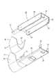
- FIG. 1 A first embodiment of the technology disclosed in this specification will be described with reference to FIGS. 1 to 7.
- the present embodiment is a shielded electric wire 12 with a terminal in which a terminal 11 is connected to the end of the shielded electric wire 10.
- the X direction is the front
- the Y direction is the right
- the Z direction is the upper.
- the shielded electric wire 10 includes an electric wire 13 (two in this embodiment), a braided wire 14 that surrounds the outer periphery of the electric wire 13, and an insulating synthetic resin that surrounds the outer periphery of the braided wire 14.
- the electric wire 13 includes a core wire 16 and an inner sheath 17 made of an insulating synthetic resin that surrounds the outer periphery of the core wire 16.
- the metal which comprises the core wire 16 can select suitably arbitrary metals as needed, such as copper, a copper alloy, aluminum, and an aluminum alloy. In this embodiment, copper or a copper alloy is used.
- the two electric wires 13 are twisted pairs twisted together.
- An inner conductor (not shown) is connected to the tip of the electric wire 13.
- the braided wire 14 is formed by knitting a plurality of fine metal wires into a cylindrical shape.
- any metal such as copper or copper alloy can be appropriately selected as required. In this embodiment, copper or a copper alloy is used.
- the outer sheath 15 of the front end portion of the shielded electric wire 10 (front end portion in the axial direction of the shielded electric wire 10) is peeled. Thereby, the electric wire 13 and the braided wire 14 are exposed from the end of the shielded electric wire 10.
- the braided wire 14 exposed from the terminal of the jacket 15 has a folded portion 18 that is folded back to the terminal side of the jacket 15.
- the folded portion 18 has a shape in which the braided wire 14 exposed forward in the axial direction from the front end portion of the outer jacket 15 is folded back in the axial direction.
- the axial direction of the shielded electric wire 10 is described as a direction parallel to the front-rear direction.
- returning part 18 is formed so that it may overlap with the jacket 15 of the shielded electric wire 10 from the outer side of the radial direction of the shielded electric wire 10.
- the sleeve 19 is formed by pressing a metal plate into a predetermined shape.
- the metal constituting the sleeve 19 any metal such as copper, copper alloy, aluminum, aluminum alloy or the like can be appropriately selected as necessary. In this embodiment, copper or a copper alloy is used.
- the sleeve 19 has an elongated plate shape.
- a longitudinal edge of the sleeve 19 is a butt edge 20.
- One of the butted edges 20 has a mountain shape when viewed from the side, and the other has a valley shape.
- the shape of the both butted edges 20 is formed so that the mountain-shaped portion and the valley-shaped portion are engaged when the both butted edges 20 are butted.
- the sleeve 19 is crimped so as to wrap around the outer periphery of the outer sheath 15 at a position outside the outer sheath 15 in the radial direction of the shielded electric wire 10 and inside the folded portion 18.
- the butted edges 20 are butted against each other.
- the butting shape between the butting edges 20 is V-shaped when viewed from above.
- the metal fine wire of the braided wire 14 is prevented from protruding into the inside of the sleeve 19 from the gap between the both butted edges 20.
- the terminal 11 is formed by pressing a metal plate material into a predetermined shape.
- a metal which comprises the terminal 11 arbitrary metals, such as copper, copper alloy, aluminum, aluminum alloy, can be selected suitably as needed. In this embodiment, copper or a copper alloy is used.
- the terminal 11 includes a lower outer conductor 21 disposed on the lower side, and an upper outer conductor 22 attached to the upper side of the lower outer conductor 21.
- the lower outer conductor 21 is provided with a plurality of lock receiving portions 23, while the upper outer conductor 22 is provided with a lock portion 24 at a position corresponding to the lock receiving portion 23.
- the lock portion 24 and the lock receiving portion 23 are elastically engaged, the lower outer conductor 21 and the upper outer conductor 22 are assembled together.
- the upper outer conductor 22 has an upper wall 25 having a substantially rectangular shape that is elongated in the front-rear direction, and side walls 26 that hang downward from the left and right edges of the upper wall 25.
- the lock portion 24 described above is provided on the side wall 26.
- the fixed piece 27 has a rectangular shape elongated in the front-rear direction when viewed from above.
- the lower outer conductor 21 includes a bottom wall 28 that is elongated in the front-rear direction when viewed from above, and a side wall 29 that extends upward from both left and right edges of the bottom wall 28.
- the lock portion described above is provided on the side wall 29.
- a barrel 30 is formed continuously behind the bottom wall 28.
- the barrel 30 is formed in an elongated plate shape extending in the left-right direction.
- the barrel 30 is crimped so as to be wound around the folded portion 18 of the shielded electric wire 10 from the outside, whereby the terminal 11 and the shielded electric wire 10 are connected.
- the end of the barrel 30 in the left-right direction is a butt edge 31 as in the case of the sleeve 19.
- One of the butted edges 31 has a mountain shape when viewed from the side, and the other has a valley shape.
- the shape of the both butted edges 31 is formed such that when the both butted edges 31 are butted, the mountain-shaped portion engages with the valley-shaped portion.
- the butted edges 31 are butted against each other.
- the butting shape between the butting edges 31 is V-shaped when viewed from above. Thereby, the metal thin wire of the braided wire 14 is prevented from protruding outside the barrel 30 from the gap between the both butted edges 31.
- a fixing piece 27 of the upper outer conductor 22 is disposed at a position below the upper end portion of the barrel 30 in a state where the barrel 30 is crimped to the folded portion 18.
- the fixed piece 27 is disposed between the folded portion 18 of the braided wire 14 and the barrel 30.
- the folded portion 18 of the braided wire 14 and the fixed piece 27 are sandwiched between the barrel 30 and the sleeve 19, so that the upper outer conductor 22 and the lower outer conductor 21 are firmly assembled. ing.
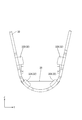
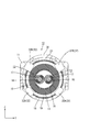
- protrusion 32 As shown in FIG. 6, at the rear end edge of the barrel 30, a plurality of (four in the present embodiment) protrusions 32 are provided in the radial direction of the shielded electric wire 10 at intervals in the circumferential direction of the shielded electric wire 10. Protrusively inward.
- the protrusion 32 has a substantially rectangular shape with rounded corners when viewed from the rear.
- the protrusion 32 is bent at a substantially right angle inward in the radial direction from the rear edge of the barrel 30.
- the rear end edge of the protrusion 32 is formed substantially flush with the rear end edge of the barrel 30.
- the protrusion 32 does not protrude rearward from the rear end edge of the barrel 30. Therefore, when pressing the barrel 30, it can suppress that the protrusion 32 interferes with the jig
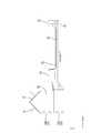
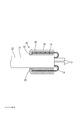
- FIG. 7 is a partially cutaway sectional view schematically showing the engagement structure between the protrusion 32 and the sleeve 19.
- the protrusion 32 in a state where the barrel 30 is crimped to the outer periphery of the folded portion 18, the protrusion 32 is disposed at a position behind the rear end portion of the sleeve 19 in the axial direction of the shielded electric wire 10. .
- the projecting dimension of the projecting portion 32 inward in the radial direction of the shielded electric wire 10 is such that the axis of the shielded electric wire 10 with respect to the rear end edge of the sleeve 19 when the barrel 30 is crimped to the outer periphery of the folded portion 18.
- the rear end edge of the sleeve 19 and the front surface of the protrusion 32 may be in contact with each other or may be separated from each other. .
- the plurality of protrusions 32 at the rear end of the barrel 30 are arranged symmetrically when viewed from the rear. As a result, when the shielded electric wire 10 is pulled rearward in the axial direction, the sleeve 19 can be received by the protrusions 32 that are arranged symmetrically, so that the force may be biased toward the specific protrusions 32. It is supposed to be suppressed.
- the four protrusions 32 have a protrusion dimension from the barrel 30 of the two protrusions 32 ⁇ / b> B located on the upper side rather than the two protrusions 32 ⁇ / b> A located on the lower side. It is set large. As shown in FIG. 6, since the fixed piece 27 of the upper outer conductor 22 is arranged below the barrel 30 located at the upper end, the barrel 30 is equivalent to the thickness dimension of the fixed piece 27. This is because the distance between the sleeve 19 and the sleeve 19 is increased.
- the two protrusions 32B located on the upper side are set so that the projecting dimension from the barrel 30 is larger than that of the protrusion 32A located on the lower side, so that the protrusion 32 reliably contacts the sleeve 19. Can be done.
- the outer sheath 15 of the shielded electric wire 10 is peeled by a predetermined length. Thereby, the electric wire 13 and the braided wire 14 are exposed from the jacket 15.
- the sleeve 19 is crimped to a position near the front end of the outer jacket 15. At this time, the butted edges 20 of the sleeve 19 are butted together.
- the braided wire 14 exposed from the front end of the jacket 15 is folded back toward the front end of the jacket 15.
- the braided wire 14 exposed from the front end portion of the outer jacket 15 is folded back to the rear in the axial direction of the shielded electric wire 10.
- the folded portion 18 is formed outside the sleeve 19 in the radial direction of the shielded electric wire 10.
- the lower outer conductor 21 and the upper outer conductor 22 are integrally assembled by elastically engaging the lock receiving portion 23 of the lower outer conductor 21 and the lock portion 24 of the upper outer conductor 22. Subsequently, the folded portion 18 of the shielded electric wire 10 is placed on the barrel 30. At this time, the fixed piece 27 is positioned above the folded portion 18.
- the barrel 30 is crimped so as to be wound around the outer periphery of the folded portion 18. Thereby, the butting edges 31 of the barrel 30 are butted together.
- the fixed piece 27 is disposed below the barrel 30, whereby the fixed piece 27 and the folded portion 18 are sandwiched between the sleeve 19 and the barrel 30. Thereby, the shielded electric wire 12 with a terminal is completed.
- a braided wire 14 is interposed between the electric wire 13 and the jacket 15, and the braided wire 14 exposed from the end of the jacket 15 is covered with the braided wire 14.
- a shielded electric wire 10 provided with a folded portion 18 that is folded back toward 15, and a metallic product that is crimped to the outer surface of the jacket 15 inside the folded portion 18 in the radial direction of the shielded electric wire 10.
- a terminal 11 having a barrel 30 that clamps the folded portion 18 between the sleeve 19 and the sleeve 19 while being crimped to the outer surface of the folded portion 18.
- the barrel 30 has an axial direction of the shielded electric wire 10.
- a protrusion 32 that protrudes inward in the radial direction of the shielded electric wire 10 is formed at a position behind the rear end of the sleeve 19.
- the shielded electric wire 10 when the shielded electric wire 10 is pulled rearward in the axial direction, the rear end portion of the sleeve 19 that is crimped to the outer sheath 15 of the shielded electric wire 10 is formed in the barrel 30 of the terminal 11.
- the projection 32 abuts from the front in the axial direction.
- the protrusion 32 protrudes inward of the radial direction of the shielded electric wire 10, compared with the case where the protrusion 32 protrudes outward of the radial direction of the shielded electric wire 10, it is a terminal.
- the attached shielded electric wire 12 can be reduced in size.
- the barrel 30 is provided with a plurality of protrusions 32 at intervals in the circumferential direction of the shielded electric wire 10.
- the braided wire 14 is formed by knitting a plurality of fine metal wires, the thickness of the folded portion 18 of the braided wire 14 may be uneven in the circumferential direction of the shielded wire 10 due to twisting or biasing of the fine metal wires. is there. In such a case, there is a concern that the central axis of the shielded electric wire 10 and the central axis of the barrel 30 are shifted in a state where the barrel 30 of the terminal 11 is crimped to the shielded electric wire 10. Then, when the shielded electric wire 10 is pulled rearward in the axial direction, there is a concern that the protrusion 32 and the sleeve 19 cannot contact each other.
- the protrusion dimension of the protrusion 32 from the barrel 30 is set so that the protrusion 32 does not contact the electric wire 13.
- the two electric wires 13 are a twisted pair, and an electric signal flows through the electric wires 13. In such a case, the technique of preventing the protrusion 32 from contacting the electric wire 13 is particularly effective.
- the protrusion dimension of the protrusion 32 ⁇ / b> A from the barrel 30 is set so that the protrusion 32 ⁇ / b> A does not contact the outer jacket 15.
- the electric wire 13 was a twisted pair, it is not restricted to this, One electric wire 13 may be sufficient and three or more may be sufficient.
- the number of the protrusions 32 may be one, two, three, or five or more.
- the protruding dimension of the protrusion 32 from the barrel 30 is set so as to be able to contact at least a part of the rear end of the sleeve 19 from the rear in the axial direction of the shielded electric wire 10. It only has to be.
- the shape of the butted portion of both butted edges 31 of the barrel 30 is V-shaped with the barrel 30 being crimped to the folded portion 18, but is not limited thereto.
- Arbitrary shapes such as a straight shape, a wave shape, and a crank shape can be adopted.
- the shape of the butted portion of the both butted edges 20 of the sleeve 19 is V-shaped, but is not limited to this, but is linear, corrugated, Arbitrary shapes, such as a crank shape, can be adopted.
- the terminal 11 has a structure in which the upper outer conductor 22 and the lower outer conductor 21 are integrally assembled.
- the present invention is not limited to this, and the terminal 11 has a barrel 30 on the cylindrical portion. It is good also as a structure formed in a row.
- the intervals between the plurality of protrusions 32 may be equal or unequal.
Landscapes
- Details Of Connecting Devices For Male And Female Coupling (AREA)
- Connections Effected By Soldering, Adhesion, Or Permanent Deformation (AREA)
Abstract
A shield electric wire 12 with a terminal comprises: a shield electric wire 10 in which a braided wire 14 is interposed between wires 13 and an outer coating 15, the braided wire 14 being provided with a foldback part 18 in which the braided wire 14 exposed from the end of the outer coating 15 is folded back towards the outer coating 15; a metal sleeve 19 pressure-bonded, on the inside of the foldback part 18 with respect to the radial direction of the shield electric wire 10, to the outer surface of the outer coating 15; and a terminal 11 having a barrel 30 that clamps the foldback part 18 with the sleeve 19, in a state of being pressure-bonded to the outer surface of the foldback part 18. A projection 32 projecting inwards with respect to the radial direction of the shield electric wire 10 is formed on the barrel 30, at a position further rearward than the rear end part of the sleeve 19 with respect to the axial direction of the shield electric wire 10.
Description
本明細書に開示された技術は、シールド電線の端末に端子が接続された、端子付きシールド電線に関する。
The technology disclosed in this specification relates to a shielded electric wire with a terminal in which a terminal is connected to a terminal of the shielded electric wire.
従来、シールド線の端末側に外導体端子が接続された端子付きシールド電線として、特許文献1に記載のものが知られている。このものは、シールド線の端末側の芯線の周りに被覆される絶縁内被とその周りに被覆される外導体編組との間に、スリーブ筒の一端に前記外導体編組を折り返す花弁状の編組折返し片を有する金属製スリーブを挿入し、その編組折返し片により外側に折り返された外導体編組を該シールド線の端末の芯線に接続される内導体端子が装着される外導体端子の後方に一体に設けられた外導体バレルにより圧着固定してなる。
Conventionally, as a shielded electric wire with a terminal in which an outer conductor terminal is connected to the terminal side of a shielded wire, the one described in Patent Document 1 is known. This is a petal-like braid that folds the outer conductor braid around one end of a sleeve tube between an insulating inner sheath that is coated around the core wire on the terminal side of the shielded wire and an outer conductor braid that is coated around the sheath. A metal sleeve having a folded piece is inserted, and the outer conductor braid folded outward by the braided folded piece is integrated behind the outer conductor terminal to which the inner conductor terminal connected to the core wire of the shield wire is attached. The outer conductor barrel provided in is fixed by crimping.
上記の構成によれば、スリーブの端縁に形成された花弁状の編組折返し片が、圧着した円環状の外導体バレルに当たりシールド線の抜脱が防止されるようになっている。これにより、シールド電線と端子との固着力の向上が図られている。
According to the above configuration, the petal-like braided folded piece formed on the edge of the sleeve hits the crimped annular outer conductor barrel to prevent the shield wire from being pulled out. Thereby, the improvement of the adhering force between the shielded electric wire and the terminal is achieved.
しかしながら上記の構成によると、スリーブの端縁に形成された花弁状の編組折返し片は、シールド電線の径方向について外方に突出した形状をなしているので、端子付きシールド電線が大型化するという問題があった。
However, according to the above configuration, the petal-like braided folded piece formed on the edge of the sleeve has a shape protruding outward in the radial direction of the shielded electric wire, so that the shielded electric wire with terminals is enlarged. There was a problem.
本明細書に開示された技術は上記のような事情に基づいて完成されたものであって、端子付きシールド電線が大型化することを抑制することを目的とする。
The technology disclosed in the present specification has been completed based on the above situation, and aims to suppress the increase in the size of the shielded electric wire with terminal.
本明細書の開示された技術は、端子付きシールド電線であって、コア線と外被との間に編組線が介在されており、前記編組線には前記外被の端末から露出した前記編組線が前記外被に向かって折り返されてなる折り返し部が設けられているシールド電線と、前記シールド電線の径方向について、前記折り返し部の内側であって、且つ前記外被の外面に圧着された金属製のスリーブと、前記折り返し部の外面に圧着された状態で前記スリーブとの間で前記折り返し部を挟持するバレルを有する端子と、を備え、前記バレルには、前記シールド電線の軸線方向について前記スリーブの後端部よりも後方の位置に、前記シールド電線の径方向の内方に突出する突部が形成されている。
The technology disclosed in this specification is a shielded electric wire with a terminal, wherein a braided wire is interposed between a core wire and a jacket, and the braid is exposed from a terminal of the jacket in the braided wire. A shielded electric wire provided with a folded portion formed by folding a wire toward the outer sheath, and the radial direction of the shielded electric wire is crimped to the inner surface of the folded portion and to the outer surface of the outer sheath A metal sleeve and a terminal having a barrel that sandwiches the folded portion between the sleeve and the sleeve while being crimped to the outer surface of the folded portion, and the barrel has an axial direction of the shielded electric wire. A protrusion projecting inward in the radial direction of the shielded electric wire is formed at a position behind the rear end of the sleeve.
上記の構成によれば、シールド電線が軸線方向について後方に引っ張られた場合に、シールド電線の外被に圧着されたスリーブの後端部は、端子のバレルに形成された突部に、軸線方向の前方から当接する。これにより、軸線方向について、シールド電線が端子に対して相対的に後方に移動することを抑制することができるので、端子とシールド電線との固着力を向上させることができる。
According to the above configuration, when the shielded electric wire is pulled rearward in the axial direction, the rear end portion of the sleeve crimped to the outer sheath of the shielded electric wire is in the axial direction on the protrusion formed on the barrel of the terminal. It abuts from the front. Thereby, since it can suppress that a shielded electric wire moves back relatively with respect to a terminal about an axial direction, the adhering force of a terminal and a shielded electric wire can be improved.
更に、上記の構成によれば、突部はシールド電線の径方向の内方に突出しているので、突部がシールド電線の径方向の外方に突出する場合に比べて、端子付きシールド電線を小型化することができる。
Furthermore, according to said structure, since the protrusion protrudes inward in the radial direction of a shielded electric wire, compared with the case where the protrusion protrudes outward in the radial direction of the shielded electric wire, It can be downsized.
本明細書に開示された技術の実施態様としては以下の態様が好ましい。
The following embodiments are preferred as embodiments of the technology disclosed in this specification.
前記バレルには、前記シールド電線の周方向について間隔を空けて複数の前記突部が設けられていることが好ましい。
It is preferable that the barrel is provided with a plurality of protrusions at intervals in the circumferential direction of the shielded electric wire.
編組線は複数の金属細線が編まれてなるので、金属細線が捩れたり偏ったりすることにより、編組線の折り返し部の厚さが、シールド電線の周方向で不均一に場合がある。この場合、シールド電線に端子のバレルが圧着された状態において、シールド電線の中心軸と、バレルの中心軸とがずれてしまうことが懸念される。すると、シールド電線が軸線方向の後方に引っ張られた場合に、突部とスリーブとが当接できないことが懸念される。上記の構成によれば、折り返し部の厚さがシールド電線の径方向について不均一になった場合でも、複数の突部の少なくとも一つが、スリーブと当接することにより、端子とシールド電線との固着力を確実に向上させることができる。
Since the braided wire is formed by knitting a plurality of fine metal wires, the thickness of the folded portion of the braided wire may be uneven in the circumferential direction of the shielded wire due to twisting or biasing of the fine metal wires. In this case, there is a concern that the central axis of the shielded electric wire and the central axis of the barrel are shifted in a state where the barrel of the terminal is crimped to the shielded electric wire. Then, when the shielded electric wire is pulled rearward in the axial direction, there is a concern that the protrusion and the sleeve cannot contact each other. According to the above configuration, even when the thickness of the folded portion becomes nonuniform in the radial direction of the shielded wire, at least one of the plurality of protrusions contacts the sleeve, thereby fixing the terminal and the shielded wire. The wearing power can be improved reliably.
前記径方向について、前記突部の前記バレルからの突出寸法は、前記突部が前記コア線に接触しないように設定されていることが好ましい。
In the radial direction, it is preferable that the protrusion dimension of the protrusion from the barrel is set so that the protrusion does not contact the core wire.
上記の構成によれば、バレルが折り返し部の外面に圧着された際に、突部が外被に貫入してコア線を傷つけることを抑制することができる。
According to the above configuration, when the barrel is pressure-bonded to the outer surface of the folded portion, it is possible to suppress the protrusion from penetrating the jacket and damaging the core wire.
前記径方向について、前記突部の前記バレルからの突出寸法は、前記突部が前記外被に接触しないように設定されていることが好ましい。
In the radial direction, it is preferable that the protrusion dimension of the protrusion from the barrel is set so that the protrusion does not contact the outer cover.
上記の構成によれば、バレルが折り返し部の外面に圧着された際に、突部が外被を傷つけることを抑制することができる。
According to the above configuration, it is possible to prevent the protrusion from damaging the outer cover when the barrel is pressure-bonded to the outer surface of the folded portion.
本明細書に開示された技術によれば、端子付きシールド電線が大型化することを抑制することができる。
According to the technology disclosed in the present specification, it is possible to suppress an increase in the size of the shielded electric wire with terminals.
<実施形態1>
本明細書に開示された技術の実施形態1を図1ないし図7を参照しつつ説明する。図1に示すように、本実施形態は、シールド電線10の端末に端子11が接続された端子付きシールド電線12である。以下の説明においては、X方向を前方とし、Y方向を右方とし、Z方向を上方として説明する。 <Embodiment 1>
A first embodiment of the technology disclosed in this specification will be described with reference to FIGS. 1 to 7. As shown in FIG. 1, the present embodiment is a shieldedelectric wire 12 with a terminal in which a terminal 11 is connected to the end of the shielded electric wire 10. In the following description, it is assumed that the X direction is the front, the Y direction is the right, and the Z direction is the upper.
本明細書に開示された技術の実施形態1を図1ないし図7を参照しつつ説明する。図1に示すように、本実施形態は、シールド電線10の端末に端子11が接続された端子付きシールド電線12である。以下の説明においては、X方向を前方とし、Y方向を右方とし、Z方向を上方として説明する。 <Embodiment 1>
A first embodiment of the technology disclosed in this specification will be described with reference to FIGS. 1 to 7. As shown in FIG. 1, the present embodiment is a shielded
(シールド電線10)
図7に示すように、シールド電線10は、電線13(本実施形態では2つ)と、電線13の外周を包囲する編組線14と、編組線14の外周を包囲する絶縁性の合成樹脂からなる外被15と、を備える。 (Shielded wire 10)
As shown in FIG. 7, the shieldedelectric wire 10 includes an electric wire 13 (two in this embodiment), a braided wire 14 that surrounds the outer periphery of the electric wire 13, and an insulating synthetic resin that surrounds the outer periphery of the braided wire 14. An outer cover 15.
図7に示すように、シールド電線10は、電線13(本実施形態では2つ)と、電線13の外周を包囲する編組線14と、編組線14の外周を包囲する絶縁性の合成樹脂からなる外被15と、を備える。 (Shielded wire 10)
As shown in FIG. 7, the shielded
図6に示すように、電線13は、芯線16と、この芯線16の外周を包囲する絶縁性の合成樹脂からなる内被17を備える。芯線16を構成する金属は、銅、銅合金、アルミニウム、アルミニウム合金等、必要に応じて任意の金属を適宜に選択できる。本実施形態においては、銅、又は銅合金が用いられている。2本の電線13は互いに撚り合わされたツイストペアとされている。電線13の先端には、図示しない内導体が接続される。
As shown in FIG. 6, the electric wire 13 includes a core wire 16 and an inner sheath 17 made of an insulating synthetic resin that surrounds the outer periphery of the core wire 16. The metal which comprises the core wire 16 can select suitably arbitrary metals as needed, such as copper, a copper alloy, aluminum, and an aluminum alloy. In this embodiment, copper or a copper alloy is used. The two electric wires 13 are twisted pairs twisted together. An inner conductor (not shown) is connected to the tip of the electric wire 13.
編組線14は、複数の金属細線を筒状に編んでなる。金属細線を構成する金属は、銅、銅合金等必要に応じて任意の金属を適宜に選択できる。本実施形態においては、銅又は銅合金が用いられている。
The braided wire 14 is formed by knitting a plurality of fine metal wires into a cylindrical shape. As the metal constituting the thin metal wire, any metal such as copper or copper alloy can be appropriately selected as required. In this embodiment, copper or a copper alloy is used.
図7に示すように、シールド電線10の前端部(シールド電線10の軸線方向の前端部)の外被15は、皮むきされている。これにより、シールド電線10の端末からは、電線13と、編組線14と、が露出している。外被15の端末から露出した編組線14は、外被15の端末側に折り返された折り返し部18を有する。換言すると、折り返し部18は、外被15の前端部から軸線方向の前方に露出した編組線14が、軸線方向の後方に折り返された形状となっている。なお、本実施形態では、シールド電線10の軸線方向を、前後方向に平行な方向として説明する。
As shown in FIG. 7, the outer sheath 15 of the front end portion of the shielded electric wire 10 (front end portion in the axial direction of the shielded electric wire 10) is peeled. Thereby, the electric wire 13 and the braided wire 14 are exposed from the end of the shielded electric wire 10. The braided wire 14 exposed from the terminal of the jacket 15 has a folded portion 18 that is folded back to the terminal side of the jacket 15. In other words, the folded portion 18 has a shape in which the braided wire 14 exposed forward in the axial direction from the front end portion of the outer jacket 15 is folded back in the axial direction. In the present embodiment, the axial direction of the shielded electric wire 10 is described as a direction parallel to the front-rear direction.
折り返し部18は、シールド電線10の外被15に対して、シールド電線10の径方向の外側から重なるように形成されている。
The folding | returning part 18 is formed so that it may overlap with the jacket 15 of the shielded electric wire 10 from the outer side of the radial direction of the shielded electric wire 10.
(スリーブ19)
図2に示すように、スリーブ19は、金属板材を所定の形状にプレス加工してなる。スリーブ19を構成する金属は、銅、銅合金、アルミニウム、アルミニウム合金等、必要に応じて任意の金属を適宜に選択できる。本実施形態においては銅又は銅合金が用いられている。 (Sleeve 19)
As shown in FIG. 2, thesleeve 19 is formed by pressing a metal plate into a predetermined shape. As the metal constituting the sleeve 19, any metal such as copper, copper alloy, aluminum, aluminum alloy or the like can be appropriately selected as necessary. In this embodiment, copper or a copper alloy is used.
図2に示すように、スリーブ19は、金属板材を所定の形状にプレス加工してなる。スリーブ19を構成する金属は、銅、銅合金、アルミニウム、アルミニウム合金等、必要に応じて任意の金属を適宜に選択できる。本実施形態においては銅又は銅合金が用いられている。 (Sleeve 19)
As shown in FIG. 2, the
スリーブ19は細長い板状をなしている。スリーブ19の長手方向の端縁は、突き合わせ縁部20とされている。突き合わせ縁部20の一方は側方から見て山状をなしており、他方は谷状をなしている。両突き合わせ縁部20の形状は、両突き合わせ縁部20が突き合わされたときに山状の部分と谷状の部分とがかみ合うように形成されている。スリーブ19は、シールド電線10の径方向について外被15の外側であって、且つ、折り返し部18の内側の位置において、外被15の外周に巻き付くように圧着されている。
The sleeve 19 has an elongated plate shape. A longitudinal edge of the sleeve 19 is a butt edge 20. One of the butted edges 20 has a mountain shape when viewed from the side, and the other has a valley shape. The shape of the both butted edges 20 is formed so that the mountain-shaped portion and the valley-shaped portion are engaged when the both butted edges 20 are butted. The sleeve 19 is crimped so as to wrap around the outer periphery of the outer sheath 15 at a position outside the outer sheath 15 in the radial direction of the shielded electric wire 10 and inside the folded portion 18.
スリーブ19が外被15に圧着された状態で、突き合わせ縁部20同士は互いに突き合わされた状態になっている。突き合わせ縁部20同士の突き合わせ形状は、上方から見て、V字状をなしている。これにより、両突き合わせ縁部20の隙間から、編組線14の金属細線がスリーブ19の内側にはみ出してくることが抑制されるようになっている。
In the state where the sleeve 19 is pressure-bonded to the outer jacket 15, the butted edges 20 are butted against each other. The butting shape between the butting edges 20 is V-shaped when viewed from above. As a result, the metal fine wire of the braided wire 14 is prevented from protruding into the inside of the sleeve 19 from the gap between the both butted edges 20.
(端子11)
端子11は、金属板材を所定の形状にプレス加工してなる。端子11を構成する金属としては、銅、銅合金、アルミニウム、アルミニウム合金等、必要に応じて任意の金属を適宜に選択することができる。本実施形態においては、銅又は銅合金が用いられている。 (Terminal 11)
The terminal 11 is formed by pressing a metal plate material into a predetermined shape. As a metal which comprises the terminal 11, arbitrary metals, such as copper, copper alloy, aluminum, aluminum alloy, can be selected suitably as needed. In this embodiment, copper or a copper alloy is used.
図2に示すように、端子11は、下側に配される下側外導体21と、この下側外導体21の上側に取り付けられる上側外導体22と、を備える。下側外導体21には複数のロック受け部23が設けられている、一方、上側外導体22には、ロック受け部23に対応する位置にロック部24が設けられている。このロック部24と、ロック受け部23とが弾性的に係合することにより、下側外導体21と、上側外導体22とが、一体に組み付けられるようになっている。
As shown in FIG. 2, the terminal 11 includes a lower outer conductor 21 disposed on the lower side, and an upper outer conductor 22 attached to the upper side of the lower outer conductor 21. The lower outer conductor 21 is provided with a plurality of lock receiving portions 23, while the upper outer conductor 22 is provided with a lock portion 24 at a position corresponding to the lock receiving portion 23. When the lock portion 24 and the lock receiving portion 23 are elastically engaged, the lower outer conductor 21 and the upper outer conductor 22 are assembled together.
上側外導体22は、前後方向に細長い略長方形状をなす上壁25と、上壁25の左右両側縁から下方に垂下する側壁26と、を有する。上記したロック部24は側壁26に設けられている。
The upper outer conductor 22 has an upper wall 25 having a substantially rectangular shape that is elongated in the front-rear direction, and side walls 26 that hang downward from the left and right edges of the upper wall 25. The lock portion 24 described above is provided on the side wall 26.
上壁25の後端部には、後方に突出する板状の固定片27が設けられている。固定片27は上方から見て前後方向に細長い長方形状をなしている。
At the rear end of the upper wall 25, a plate-like fixing piece 27 protruding backward is provided. The fixed piece 27 has a rectangular shape elongated in the front-rear direction when viewed from above.
下側外導体21は、上方から見て前後方向に細長い長方形状をなす底壁28と、底壁28の左右両側縁から上方に延びる側壁29と、を備える。上述したロック部は側壁29に設けられている。底壁28の後方には、バレル30が連なって形成されている。
The lower outer conductor 21 includes a bottom wall 28 that is elongated in the front-rear direction when viewed from above, and a side wall 29 that extends upward from both left and right edges of the bottom wall 28. The lock portion described above is provided on the side wall 29. A barrel 30 is formed continuously behind the bottom wall 28.
バレル30は左右方向に延びる細長い板状に形成されている。このバレル30が、シールド電線10の折り返し部18に対して外側から巻き付くように圧着されることにより、端子11とシールド電線10とが接続されるようになっている。
The barrel 30 is formed in an elongated plate shape extending in the left-right direction. The barrel 30 is crimped so as to be wound around the folded portion 18 of the shielded electric wire 10 from the outside, whereby the terminal 11 and the shielded electric wire 10 are connected.
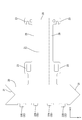
図5に示すように、バレル30の左右方向の端部は、スリーブ19の場合と同様に、突き合わせ縁部31とされている。突き合わせ縁部31の一方は側方から見て山状をなしており、他方は谷状をなしている。両突き合わせ縁部31の形状は、両突き合わせ縁部31が突き合わされたときに山状の部分が谷状の部分にかみ合うように形成されている。
As shown in FIG. 5, the end of the barrel 30 in the left-right direction is a butt edge 31 as in the case of the sleeve 19. One of the butted edges 31 has a mountain shape when viewed from the side, and the other has a valley shape. The shape of the both butted edges 31 is formed such that when the both butted edges 31 are butted, the mountain-shaped portion engages with the valley-shaped portion.
バレル30が折り返し部18に圧着された状態で、突き合わせ縁部31同士は互いに突き合わされた状態になっている。突き合わせ縁部31同士の突き合わせ形状は、上方から見て、V字状をなしている。これにより、両突き合わせ縁部31の隙間から、編組線14の金属細線がバレル30の外側にはみ出してくることが抑制されるようになっている。
In the state where the barrel 30 is pressure-bonded to the folded-back portion 18, the butted edges 31 are butted against each other. The butting shape between the butting edges 31 is V-shaped when viewed from above. Thereby, the metal thin wire of the braided wire 14 is prevented from protruding outside the barrel 30 from the gap between the both butted edges 31.
図6に示すように、バレル30が折り返し部18に圧着された状態において、バレル30の上端部分の下方の位置には、上側外導体22の固定片27が配されている。換言すると、固定片27は、編組線14の折り返し部18と、バレル30との間に配されている。これにより、バレル30とスリーブ19との間に、編組線14の折り返し部18と固定片27とが挟持されるので、上側外導体22と下側外導体21とが強固に組み付けられるようになっている。
As shown in FIG. 6, a fixing piece 27 of the upper outer conductor 22 is disposed at a position below the upper end portion of the barrel 30 in a state where the barrel 30 is crimped to the folded portion 18. In other words, the fixed piece 27 is disposed between the folded portion 18 of the braided wire 14 and the barrel 30. As a result, the folded portion 18 of the braided wire 14 and the fixed piece 27 are sandwiched between the barrel 30 and the sleeve 19, so that the upper outer conductor 22 and the lower outer conductor 21 are firmly assembled. ing.
(突部32)
図6に示すように、バレル30の後端縁には、シールド電線10の周方向について間隔を空けて、複数(本実施形態では4つ)の突部32が、シールド電線10の径方向の内方に突出している。突部32は後方から見て角の丸められた略長方形状をなしている。突部32は、バレル30の後端縁から、径方向の内方に略直角に曲げ加工されてなる。 (Projection 32)
As shown in FIG. 6, at the rear end edge of thebarrel 30, a plurality of (four in the present embodiment) protrusions 32 are provided in the radial direction of the shielded electric wire 10 at intervals in the circumferential direction of the shielded electric wire 10. Protrusively inward. The protrusion 32 has a substantially rectangular shape with rounded corners when viewed from the rear. The protrusion 32 is bent at a substantially right angle inward in the radial direction from the rear edge of the barrel 30.
図6に示すように、バレル30の後端縁には、シールド電線10の周方向について間隔を空けて、複数(本実施形態では4つ)の突部32が、シールド電線10の径方向の内方に突出している。突部32は後方から見て角の丸められた略長方形状をなしている。突部32は、バレル30の後端縁から、径方向の内方に略直角に曲げ加工されてなる。 (Projection 32)
As shown in FIG. 6, at the rear end edge of the
図4に示すように、突部32の後端縁は、バレル30の後端縁と略面一に形成されている。換言すると、突部32は、バレル30の後端縁より後方には突出していない。これによりバレル30をプレス加工する際に、突部32がプレス加工のための治具等に干渉することを抑制することができる。
As shown in FIG. 4, the rear end edge of the protrusion 32 is formed substantially flush with the rear end edge of the barrel 30. In other words, the protrusion 32 does not protrude rearward from the rear end edge of the barrel 30. Thereby, when pressing the barrel 30, it can suppress that the protrusion 32 interferes with the jig | tool for press processing, etc.
図7に、突部32とスリーブ19との係合構造を模式的に示した一部切り欠き断面図を示す。図7に示すように、バレル30が折り返し部18の外周に圧着された状態において、突部32は、シールド電線10の軸線方向についてスリーブ19の後端部よりも後方の位置に配されている。突部32の、シールド電線10の径方向の内方への突出寸法は、バレル30が折り返し部18の外周に圧着された状態において、スリーブ19の後端縁に対して、シールド電線10の軸線方向の後方から係止可能に設定されている。これにより、シールド電線10に対して、軸線方向について後方に引っ張られる力が加えられた場合に、突部32が、軸線方向の後方からスリーブ19の後端縁に当接するようになっている。
FIG. 7 is a partially cutaway sectional view schematically showing the engagement structure between the protrusion 32 and the sleeve 19. As shown in FIG. 7, in a state where the barrel 30 is crimped to the outer periphery of the folded portion 18, the protrusion 32 is disposed at a position behind the rear end portion of the sleeve 19 in the axial direction of the shielded electric wire 10. . The projecting dimension of the projecting portion 32 inward in the radial direction of the shielded electric wire 10 is such that the axis of the shielded electric wire 10 with respect to the rear end edge of the sleeve 19 when the barrel 30 is crimped to the outer periphery of the folded portion 18. It is set so that it can be locked from the rear of the direction. As a result, when a force pulled rearward in the axial direction is applied to the shielded electric wire 10, the protrusion 32 comes into contact with the rear end edge of the sleeve 19 from the rear in the axial direction.
シールド電線10が、軸線方向の後方へ引っ張られていない状態においては、スリーブ19の後端縁と、突部32の前面とは、当接していてもよいし、また、離間していてもよい。
In a state where the shielded electric wire 10 is not pulled rearward in the axial direction, the rear end edge of the sleeve 19 and the front surface of the protrusion 32 may be in contact with each other or may be separated from each other. .
バレル30の後端部における複数の突部32は、後方から見て、左右対称に配されている。これにより、シールド電線10が軸線方向の後方へ引っ張られたときに、左右対称に配された突部32によってスリーブ19を受けることができるので、力が特定の突部32に偏ってしまうことが抑制されるようになっている。
The plurality of protrusions 32 at the rear end of the barrel 30 are arranged symmetrically when viewed from the rear. As a result, when the shielded electric wire 10 is pulled rearward in the axial direction, the sleeve 19 can be received by the protrusions 32 that are arranged symmetrically, so that the force may be biased toward the specific protrusions 32. It is supposed to be suppressed.
図5及び図6に示すように、4つの突部32は、下側に位置する2つの突部32Aよりも、上側に位置する2つの突部32Bの方が、バレル30からの突出寸法が大きく設定されている。これは、図6に示すように、上端に位置するバレル30の下方には、上側外導体22の固定片27が配されているので、この固定片27の厚さ寸法の分だけ、バレル30とスリーブ19との間隔が広くなっているからである。上側に位置する2つの突部32Bの方が、バレル30からの突出寸法が下側に位置する突部32Aよりも大きく設定されていることにより、突部32が確実にスリーブ19に当接することができるようになっている。
As shown in FIGS. 5 and 6, the four protrusions 32 have a protrusion dimension from the barrel 30 of the two protrusions 32 </ b> B located on the upper side rather than the two protrusions 32 </ b> A located on the lower side. It is set large. As shown in FIG. 6, since the fixed piece 27 of the upper outer conductor 22 is arranged below the barrel 30 located at the upper end, the barrel 30 is equivalent to the thickness dimension of the fixed piece 27. This is because the distance between the sleeve 19 and the sleeve 19 is increased. The two protrusions 32B located on the upper side are set so that the projecting dimension from the barrel 30 is larger than that of the protrusion 32A located on the lower side, so that the protrusion 32 reliably contacts the sleeve 19. Can be done.
(端子付きシールド電線12の製造工程)
続いて、端子付きシールド電線12の製造工程の一例について説明する。なお、端子付きシールド電線12の工程は下記の工程に限定されない。 (Manufacturing process of shieldedelectric wire 12 with terminal)
Then, an example of the manufacturing process of the shieldedelectric wire 12 with a terminal is demonstrated. In addition, the process of the shielded electric wire 12 with a terminal is not limited to the following process.
続いて、端子付きシールド電線12の製造工程の一例について説明する。なお、端子付きシールド電線12の工程は下記の工程に限定されない。 (Manufacturing process of shielded
Then, an example of the manufacturing process of the shielded
シールド電線10の外被15を、所定の長さ寸法だけ皮むきする。これにより、電線13と、編組線14とを、外被15から露出させる。
The outer sheath 15 of the shielded electric wire 10 is peeled by a predetermined length. Thereby, the electric wire 13 and the braided wire 14 are exposed from the jacket 15.
次に、外被15の前端部寄りの位置に、スリーブ19を圧着する。このとき、スリーブ19の突き合わせ縁部20同士を突き合わせる。
Next, the sleeve 19 is crimped to a position near the front end of the outer jacket 15. At this time, the butted edges 20 of the sleeve 19 are butted together.
続いて、外被15の前端部から露出した編組線14を、外被15の前端部に向かって折り返す。換言すれば、外被15の前端部から露出した編組線14を、シールド電線10の軸線方向の後方に折り返す。これにより、シールド電線10の径方向についてスリーブ19の外側に折り返し部18を形成する。
Subsequently, the braided wire 14 exposed from the front end of the jacket 15 is folded back toward the front end of the jacket 15. In other words, the braided wire 14 exposed from the front end portion of the outer jacket 15 is folded back to the rear in the axial direction of the shielded electric wire 10. Thus, the folded portion 18 is formed outside the sleeve 19 in the radial direction of the shielded electric wire 10.
一方、下側外導体21のロック受け部23と、上側外導体22のロック部24とを弾性的に係合させることで、下側外導体21と上側外導体22とを一体に組み付ける。続いて、シールド電線10の折り返し部18をバレル30の上に載置する。このとき、折り返し部18の上側に固定片27が位置するようにする。
On the other hand, the lower outer conductor 21 and the upper outer conductor 22 are integrally assembled by elastically engaging the lock receiving portion 23 of the lower outer conductor 21 and the lock portion 24 of the upper outer conductor 22. Subsequently, the folded portion 18 of the shielded electric wire 10 is placed on the barrel 30. At this time, the fixed piece 27 is positioned above the folded portion 18.
バレル30を、折り返し部18の外周に巻き付けるようにして圧着する。これにより、バレル30の突き合わせ縁部31同士を突き合わせる。このとき、バレル30の下側に固定片27が配されることにより、固定片27と折り返し部18とが、スリーブ19とバレル30との間に挟持される。これにより、端子付きシールド電線12が完成する。
The barrel 30 is crimped so as to be wound around the outer periphery of the folded portion 18. Thereby, the butting edges 31 of the barrel 30 are butted together. At this time, the fixed piece 27 is disposed below the barrel 30, whereby the fixed piece 27 and the folded portion 18 are sandwiched between the sleeve 19 and the barrel 30. Thereby, the shielded electric wire 12 with a terminal is completed.
(実施形態の作用、効果)
続いて、本実施形態の作用、効果について説明する。本実施形態に係る端子付きシールド電線12は、電線13と外被15との間に編組線14が介在されており、編組線14には外被15の端末から露出した編組線14が外被15に向かって折り返されてなる折り返し部18が設けられているシールド電線10と、シールド電線10の径方向について、折り返し部18の内側であって、且つ外被15の外面に圧着された金属製のスリーブ19と、折り返し部18の外面に圧着された状態でスリーブ19との間で折り返し部18を挟持するバレル30を有する端子11と、を備え、バレル30には、シールド電線10の軸線方向についてスリーブ19の後端部よりも後方の位置に、シールド電線10の径方向の内方に突出する突部32が形成されている。 (Operation and effect of the embodiment)
Then, the effect | action and effect of this embodiment are demonstrated. In the shieldedelectric wire 12 with a terminal according to the present embodiment, a braided wire 14 is interposed between the electric wire 13 and the jacket 15, and the braided wire 14 exposed from the end of the jacket 15 is covered with the braided wire 14. A shielded electric wire 10 provided with a folded portion 18 that is folded back toward 15, and a metallic product that is crimped to the outer surface of the jacket 15 inside the folded portion 18 in the radial direction of the shielded electric wire 10. And a terminal 11 having a barrel 30 that clamps the folded portion 18 between the sleeve 19 and the sleeve 19 while being crimped to the outer surface of the folded portion 18. The barrel 30 has an axial direction of the shielded electric wire 10. A protrusion 32 that protrudes inward in the radial direction of the shielded electric wire 10 is formed at a position behind the rear end of the sleeve 19.
続いて、本実施形態の作用、効果について説明する。本実施形態に係る端子付きシールド電線12は、電線13と外被15との間に編組線14が介在されており、編組線14には外被15の端末から露出した編組線14が外被15に向かって折り返されてなる折り返し部18が設けられているシールド電線10と、シールド電線10の径方向について、折り返し部18の内側であって、且つ外被15の外面に圧着された金属製のスリーブ19と、折り返し部18の外面に圧着された状態でスリーブ19との間で折り返し部18を挟持するバレル30を有する端子11と、を備え、バレル30には、シールド電線10の軸線方向についてスリーブ19の後端部よりも後方の位置に、シールド電線10の径方向の内方に突出する突部32が形成されている。 (Operation and effect of the embodiment)
Then, the effect | action and effect of this embodiment are demonstrated. In the shielded
上記の構成によれば、シールド電線10が軸線方向について後方に引っ張られた場合に、シールド電線10の外被15に圧着されたスリーブ19の後端部は、端子11のバレル30に形成された突部32に、軸線方向の前方から当接する。これにより、軸線方向について、シールド電線10が端子11に対して相対的に後方に移動することを抑制することができるので、端子11とシールド電線10との固着力を向上させることができる。
According to the above configuration, when the shielded electric wire 10 is pulled rearward in the axial direction, the rear end portion of the sleeve 19 that is crimped to the outer sheath 15 of the shielded electric wire 10 is formed in the barrel 30 of the terminal 11. The projection 32 abuts from the front in the axial direction. Thereby, since it can suppress that the shield electric wire 10 moves back relatively with respect to the terminal 11 about an axial direction, the adhering force of the terminal 11 and the shield electric wire 10 can be improved.
更に、上記の構成によれば、突部32はシールド電線10の径方向の内方に突出しているので、突部32がシールド電線10の径方向の外方に突出する場合に比べて、端子付きシールド電線12を小型化することができる。
Furthermore, according to said structure, since the protrusion 32 protrudes inward of the radial direction of the shielded electric wire 10, compared with the case where the protrusion 32 protrudes outward of the radial direction of the shielded electric wire 10, it is a terminal. The attached shielded electric wire 12 can be reduced in size.
また、本実施形態によれば、バレル30には、シールド電線10の周方向について間隔を空けて複数の突部32が設けられている。
Further, according to the present embodiment, the barrel 30 is provided with a plurality of protrusions 32 at intervals in the circumferential direction of the shielded electric wire 10.
編組線14は複数の金属細線が編まれてなるので、金属細線が捩れたり偏ったりすることにより、編組線14の折り返し部18の厚さが、シールド電線10の周方向で不均一に場合がある。このような場合、シールド電線10に端子11のバレル30が圧着された状態において、シールド電線10の中心軸と、バレル30の中心軸とがずれてしまうことが懸念される。すると、シールド電線10が軸線方向の後方に引っ張られた場合に、突部32とスリーブ19とが当接できないことが懸念される。上記の構成によれば、折り返し部18の厚さがシールド電線10の径方向について不均一になった場合でも、複数の突部32の少なくとも一つが、スリーブ19と当接することにより、端子11とシールド電線10との固着力を確実に向上させることができる。
Since the braided wire 14 is formed by knitting a plurality of fine metal wires, the thickness of the folded portion 18 of the braided wire 14 may be uneven in the circumferential direction of the shielded wire 10 due to twisting or biasing of the fine metal wires. is there. In such a case, there is a concern that the central axis of the shielded electric wire 10 and the central axis of the barrel 30 are shifted in a state where the barrel 30 of the terminal 11 is crimped to the shielded electric wire 10. Then, when the shielded electric wire 10 is pulled rearward in the axial direction, there is a concern that the protrusion 32 and the sleeve 19 cannot contact each other. According to the above configuration, even when the thickness of the folded portion 18 is not uniform in the radial direction of the shielded electric wire 10, at least one of the plurality of protrusions 32 comes into contact with the sleeve 19, thereby The fixing force with the shielded electric wire 10 can be improved reliably.
また、本実施形態によれば、シールド電線10の径方向について、突部32のバレル30からの突出寸法は、突部32が電線13に接触しないように設定されている。
Further, according to the present embodiment, in the radial direction of the shielded electric wire 10, the protrusion dimension of the protrusion 32 from the barrel 30 is set so that the protrusion 32 does not contact the electric wire 13.
上記の構成によれば、バレル30が折り返し部18の外面に圧着された際に、突部32が外被15に貫入して電線13を傷つけることを抑制することができる。本実施形態においては2本の電線13はツイストペアとされており、電線13には電気信号が流されるようになっている。このような場合に、突部32が電線13に接触しないようにするという技術は、特に有効である。
According to the above configuration, when the barrel 30 is pressure-bonded to the outer surface of the folded portion 18, it is possible to suppress the protrusion 32 from penetrating the outer sheath 15 and damaging the electric wire 13. In the present embodiment, the two electric wires 13 are a twisted pair, and an electric signal flows through the electric wires 13. In such a case, the technique of preventing the protrusion 32 from contacting the electric wire 13 is particularly effective.
また、本実施形態によれば、シールド電線10の径方向について、突部32Aのバレル30からの突出寸法は、突部32Aが外被15に接触しないように設定されている。
Further, according to the present embodiment, in the radial direction of the shielded electric wire 10, the protrusion dimension of the protrusion 32 </ b> A from the barrel 30 is set so that the protrusion 32 </ b> A does not contact the outer jacket 15.
上記の構成によれば、バレル30が折り返し部18の外面に圧着された際に、突部32Aが外被15を傷つけることを抑制することができる。
According to the above configuration, it is possible to suppress the protrusion 32A from damaging the outer jacket 15 when the barrel 30 is crimped to the outer surface of the folded portion 18.
<他の実施形態>
本明細書に開示された技術は上記記述及び図面によって説明した実施形態に限定されるものではなく、例えば次のような実施形態も本明細書に開示された技術の技術的範囲に含まれる。 <Other embodiments>
The technology disclosed in the present specification is not limited to the embodiments described with reference to the above description and drawings, and for example, the following embodiments are also included in the technical scope of the technology disclosed in the present specification.
(1)本実施形態においては、電線13はツイストペアであったが、これに限られず、電線13は1本でもよいし、また、3本以上であってもよい。
(1) In this embodiment, although the electric wire 13 was a twisted pair, it is not restricted to this, One electric wire 13 may be sufficient and three or more may be sufficient.
(2)突部32は、1つ、2つ、3つ又は5つ以上であってもよい。
(2) The number of the protrusions 32 may be one, two, three, or five or more.
(3)シールド電線10の径方向について、突部32のバレル30からの突出寸法は、スリーブ19の後端部の少なくとも一部に、シールド電線10の軸線方向の後方から当接可能に設定されていればよい。
(3) With respect to the radial direction of the shielded electric wire 10, the protruding dimension of the protrusion 32 from the barrel 30 is set so as to be able to contact at least a part of the rear end of the sleeve 19 from the rear in the axial direction of the shielded electric wire 10. It only has to be.
(4)本実施形態においては、バレル30が折り返し部18に圧着された状態で、バレル30の両突き合わせ縁部31の突き合わせ部分の形状は、V字状をなしていたが、これに限られず、直線状、波形状、クランク形状等、任意の形状を採用することができる。また、スリーブ19がシールド電線10に圧着された状態で、スリーブ19の両突き合わせ縁部20の突き合わせ部分の形状は、V字状をなしていたが、これに限られず、直線状、波形状、クランク形状等、任意の形状を採用することができる。
(4) In the present embodiment, the shape of the butted portion of both butted edges 31 of the barrel 30 is V-shaped with the barrel 30 being crimped to the folded portion 18, but is not limited thereto. Arbitrary shapes such as a straight shape, a wave shape, and a crank shape can be adopted. Further, in the state where the sleeve 19 is crimped to the shielded electric wire 10, the shape of the butted portion of the both butted edges 20 of the sleeve 19 is V-shaped, but is not limited to this, but is linear, corrugated, Arbitrary shapes, such as a crank shape, can be adopted.
(5)本実施形態においては、端子11は、上側外導体22と、下側外導体21とを一体に組み付ける構成としたが、これに限られず、端子11は、筒状部にバレル30が一体に連なって形成される構成としてもよい。
(5) In the present embodiment, the terminal 11 has a structure in which the upper outer conductor 22 and the lower outer conductor 21 are integrally assembled. However, the present invention is not limited to this, and the terminal 11 has a barrel 30 on the cylindrical portion. It is good also as a structure formed in a row.
(6)複数の突部32同士の間隔は、等間隔であってもよいし、不均等であってもよい。
(6) The intervals between the plurality of protrusions 32 may be equal or unequal.
10:シールド電線
11:端子
12:端子付きシールド電線
13:電線
14:編組線
15:外被
18:折り返し部
19:スリーブ
30:バレル
32:突部 10: Shielded wire 11: Terminal 12: Shielded wire with terminal 13: Wire 14: Braided wire 15: Outer sheath 18: Folded portion 19: Sleeve 30: Barrel 32: Projection
11:端子
12:端子付きシールド電線
13:電線
14:編組線
15:外被
18:折り返し部
19:スリーブ
30:バレル
32:突部 10: Shielded wire 11: Terminal 12: Shielded wire with terminal 13: Wire 14: Braided wire 15: Outer sheath 18: Folded portion 19: Sleeve 30: Barrel 32: Projection
Claims (4)
- コア線と外被との間に編組線が介在されており、前記編組線には前記外被の端末から露出した前記編組線が前記外被に向かって折り返されてなる折り返し部が設けられているシールド電線と、
前記シールド電線の径方向について、前記折り返し部の内側であって、且つ前記外被の外面に圧着された金属製のスリーブと、
前記折り返し部の外面に圧着された状態で前記スリーブとの間で前記折り返し部を挟持するバレルを有する端子と、を備え、
前記バレルには、前記シールド電線の軸線方向について前記スリーブの後端部よりも後方の位置に、前記シールド電線の径方向の内方に突出する突部が形成されている、端子付きシールド電線。 A braided wire is interposed between the core wire and the jacket, and the braided wire is provided with a folded portion formed by folding the braided wire exposed from the terminal of the jacket toward the jacket. A shielded wire,
For the radial direction of the shielded wire, a metal sleeve that is inside the folded portion and is crimped to the outer surface of the jacket;
A terminal having a barrel that sandwiches the folded portion between the sleeve and the sleeve while being crimped to the outer surface of the folded portion,
A shielded electric wire with a terminal, wherein the barrel is formed with a protrusion protruding inward in the radial direction of the shielded electric wire at a position rearward of the rear end of the sleeve in the axial direction of the shielded electric wire. - 前記バレルには、前記シールド電線の周方向について間隔を空けて複数の前記突部が設けられている、請求項1に記載の端子付きシールド電線。 The shielded electric wire with a terminal according to claim 1, wherein the barrel is provided with a plurality of protrusions at intervals in the circumferential direction of the shielded electric wire.
- 前記径方向について、前記突部の前記バレルからの突出寸法は、前記突部が前記コア線に接触しないように設定されている、請求項1または請求項2記載の端子付きシールド電線。 3. The shielded electric wire with a terminal according to claim 1, wherein the protrusion dimension of the protrusion from the barrel is set so that the protrusion does not contact the core wire in the radial direction.
- 前記径方向について、前記突部の前記バレルからの突出寸法は、前記突部が前記外被に接触しないように設定されている、請求項1から請求項3のいずれか一項に記載の端子付きシールド電線。 The terminal according to any one of claims 1 to 3, wherein the protrusion dimension of the protrusion from the barrel is set so that the protrusion does not contact the outer cover in the radial direction. Shielded electric wire with.
Priority Applications (2)
| Application Number | Priority Date | Filing Date | Title |
|---|---|---|---|
| CN201880014815.1A CN110352537B (en) | 2017-03-01 | 2018-02-19 | Shielded electric wire with terminal |
| US16/490,051 US10910734B2 (en) | 2017-03-01 | 2018-02-19 | Shielded cable with terminal |
Applications Claiming Priority (2)
| Application Number | Priority Date | Filing Date | Title |
|---|---|---|---|
| JP2017038120A JP6780546B2 (en) | 2017-03-01 | 2017-03-01 | Shielded wire with terminal |
| JP2017-038120 | 2017-03-01 |
Publications (1)
| Publication Number | Publication Date |
|---|---|
| WO2018159351A1 true WO2018159351A1 (en) | 2018-09-07 |
Family
ID=63370674
Family Applications (1)
| Application Number | Title | Priority Date | Filing Date |
|---|---|---|---|
| PCT/JP2018/005670 WO2018159351A1 (en) | 2017-03-01 | 2018-02-19 | Shield electric wire with terminal |
Country Status (4)
| Country | Link |
|---|---|
| US (1) | US10910734B2 (en) |
| JP (1) | JP6780546B2 (en) |
| CN (1) | CN110352537B (en) |
| WO (1) | WO2018159351A1 (en) |
Cited By (4)
| Publication number | Priority date | Publication date | Assignee | Title |
|---|---|---|---|---|
| CN109524800A (en) * | 2018-12-29 | 2019-03-26 | 南京全信光电系统有限公司 | A kind of weapon system bus cable component line connects device and preparation method thereof |
| EP3783755A1 (en) * | 2019-08-20 | 2021-02-24 | Aptiv Technologies Limited | Assembly comprising a connector and a cable |
| WO2021230039A1 (en) * | 2020-05-14 | 2021-11-18 | 株式会社オートネットワーク技術研究所 | Shielded electrically conductive path |
| CN109524800B (en) * | 2018-12-29 | 2024-05-31 | 南京全信光电系统有限公司 | Weapon system bus cable assembly connector and preparation method thereof |
Families Citing this family (6)
| Publication number | Priority date | Publication date | Assignee | Title |
|---|---|---|---|---|
| JP6955219B2 (en) * | 2018-03-30 | 2021-10-27 | 住友電装株式会社 | Wire harness |
| JP7096123B2 (en) * | 2018-10-01 | 2022-07-05 | 矢崎総業株式会社 | Terminal connection structure of shielded wire |
| JP7240607B2 (en) * | 2019-08-09 | 2023-03-16 | 株式会社オートネットワーク技術研究所 | connector with cable |
| JP7435338B2 (en) * | 2020-07-27 | 2024-02-21 | 住友電装株式会社 | Terminal structure and sleeve of shielded wire |
| CN112002469B (en) * | 2020-08-18 | 2022-02-11 | 昆山联滔电子有限公司 | Cable and processing method thereof |
| JP2022165000A (en) * | 2021-04-19 | 2022-10-31 | 株式会社オートネットワーク技術研究所 | connector with cable |
Citations (2)
| Publication number | Priority date | Publication date | Assignee | Title |
|---|---|---|---|---|
| JP2006244816A (en) * | 2005-03-02 | 2006-09-14 | Sumitomo Wiring Syst Ltd | Mounting structure of terminal fitting to shielded wire |
| JP2010182632A (en) * | 2009-02-09 | 2010-08-19 | Autonetworks Technologies Ltd | Fixing member for cable connector, cable connector, cable with the same, and optical cable connector |
Family Cites Families (17)
| Publication number | Priority date | Publication date | Assignee | Title |
|---|---|---|---|---|
| US2777894A (en) * | 1956-03-05 | 1957-01-15 | Jerrold Electronics Corp | Male connector |
| DE4226904C2 (en) * | 1992-08-14 | 1995-06-08 | Framatome Connectors Deutschla | Crimp sleeve |
| US5679926A (en) * | 1996-02-22 | 1997-10-21 | General Motors Corporation | Sleeve retainer for sensor |
| US6508678B1 (en) * | 2000-08-31 | 2003-01-21 | Advanced Connecteck Inc. | Electrical connector assembly |
| JP2002208461A (en) | 2001-01-12 | 2002-07-26 | Auto Network Gijutsu Kenkyusho:Kk | Shield wire terminal connection structure |
| US6692299B1 (en) * | 2002-11-04 | 2004-02-17 | Hitachi Cable Indiana, Inc. | Electrical connector for coaxial cable |
| JP4316482B2 (en) * | 2004-12-03 | 2009-08-19 | 矢崎総業株式会社 | Grounding method and grounding structure of shielded wire |
| JP2009099300A (en) * | 2007-10-15 | 2009-05-07 | Sumitomo Wiring Syst Ltd | Shield connector |
| JP2009129865A (en) * | 2007-11-27 | 2009-06-11 | Jst Mfg Co Ltd | Grasping shield connector assembly kit, and shield cable harness |
| JP6089288B2 (en) * | 2011-05-19 | 2017-03-08 | 矢崎総業株式会社 | Shielded wire |
| JP5367017B2 (en) * | 2011-06-03 | 2013-12-11 | 株式会社ソニー・コンピュータエンタテインメント | cable |
| JP5762219B2 (en) * | 2011-08-31 | 2015-08-12 | 矢崎総業株式会社 | Method of connecting braided shield layer of shielded wire and drain wire, and connection structure |
| JP5945155B2 (en) * | 2012-05-07 | 2016-07-05 | 矢崎総業株式会社 | Connection structure of external conductor terminal of electric wire |
| JP2014017181A (en) * | 2012-07-11 | 2014-01-30 | Tyco Electronics Japan Kk | Terminal structure of shield cable harness and manufacturing method therefor |
| JP6168416B2 (en) * | 2014-05-28 | 2017-07-26 | 株式会社オートネットワーク技術研究所 | Shielded wire with terminal bracket |
| US10333247B2 (en) * | 2015-03-19 | 2019-06-25 | Hitachi Metals, Ltd. | Wire harness |
| EP3242359B1 (en) * | 2016-05-04 | 2019-07-17 | MD Elektronik GmbH | Cable |
-
2017
- 2017-03-01 JP JP2017038120A patent/JP6780546B2/en active Active
-
2018
- 2018-02-19 WO PCT/JP2018/005670 patent/WO2018159351A1/en active Application Filing
- 2018-02-19 US US16/490,051 patent/US10910734B2/en active Active
- 2018-02-19 CN CN201880014815.1A patent/CN110352537B/en active Active
Patent Citations (2)
| Publication number | Priority date | Publication date | Assignee | Title |
|---|---|---|---|---|
| JP2006244816A (en) * | 2005-03-02 | 2006-09-14 | Sumitomo Wiring Syst Ltd | Mounting structure of terminal fitting to shielded wire |
| JP2010182632A (en) * | 2009-02-09 | 2010-08-19 | Autonetworks Technologies Ltd | Fixing member for cable connector, cable connector, cable with the same, and optical cable connector |
Cited By (8)
| Publication number | Priority date | Publication date | Assignee | Title |
|---|---|---|---|---|
| CN109524800A (en) * | 2018-12-29 | 2019-03-26 | 南京全信光电系统有限公司 | A kind of weapon system bus cable component line connects device and preparation method thereof |
| CN109524800B (en) * | 2018-12-29 | 2024-05-31 | 南京全信光电系统有限公司 | Weapon system bus cable assembly connector and preparation method thereof |
| EP3783755A1 (en) * | 2019-08-20 | 2021-02-24 | Aptiv Technologies Limited | Assembly comprising a connector and a cable |
| CN112436342A (en) * | 2019-08-20 | 2021-03-02 | Aptiv技术有限公司 | Assembly comprising a connector and a cable |
| US11664629B2 (en) | 2019-08-20 | 2023-05-30 | Aptiv Technologies Limited | Assembly comprising a connector and a cable |
| WO2021230039A1 (en) * | 2020-05-14 | 2021-11-18 | 株式会社オートネットワーク技術研究所 | Shielded electrically conductive path |
| JP2021180115A (en) * | 2020-05-14 | 2021-11-18 | 株式会社オートネットワーク技術研究所 | Shield conductive path |
| JP7406711B2 (en) | 2020-05-14 | 2023-12-28 | 株式会社オートネットワーク技術研究所 | shield conductive path |
Also Published As
| Publication number | Publication date |
|---|---|
| CN110352537B (en) | 2021-01-26 |
| CN110352537A (en) | 2019-10-18 |
| JP2018147564A (en) | 2018-09-20 |
| JP6780546B2 (en) | 2020-11-04 |
| US10910734B2 (en) | 2021-02-02 |
| US20200014129A1 (en) | 2020-01-09 |
Similar Documents
| Publication | Publication Date | Title |
|---|---|---|
| WO2018159351A1 (en) | Shield electric wire with terminal | |
| JP7240607B2 (en) | connector with cable | |
| JP6745043B2 (en) | Shield terminal | |
| US10504637B2 (en) | Shielded conduction path | |
| JP7096123B2 (en) | Terminal connection structure of shielded wire | |
| JP2018113176A (en) | Shield conductive path | |
| JP2009224033A (en) | Inner conductor terminal integrated with insulator with electronic component mounted thereon and coaxial connector | |
| JP2005093173A (en) | Shielding terminal for coaxial cable | |
| JP6290957B2 (en) | Shield terminal connection structure | |
| CN110518431B (en) | Terminal crimping method and terminal crimping structure | |
| WO2014129417A1 (en) | Connection structure for shielded braided wire, and shielded connector | |
| JP4530890B2 (en) | Coaxial cable terminal processing structure and coaxial cable shield terminal | |
| WO2020129624A1 (en) | Connector structure, and method for manufacturing connector structure | |
| JP5424055B2 (en) | Terminal fitting | |
| WO2017195547A1 (en) | Terminal-equipped electric wire, and terminal | |
| US10136566B2 (en) | Electromagnetic shielding member | |
| CN113196584A (en) | Connector structure | |
| WO2017221668A1 (en) | Terminal and electrical cable with terminal | |
| JP2016167351A (en) | Fixing member | |
| JP4392381B2 (en) | Shield connector | |
| JP2021086677A (en) | Connection structure of shield wire | |
| JP2015232962A (en) | Electric wire module and pipe | |
| WO2023199745A1 (en) | Shielded electroconductive path | |
| JP5906543B2 (en) | Electric wire with crimp terminal | |
| JP2016213134A (en) | connector |
Legal Events
| Date | Code | Title | Description |
|---|---|---|---|
| 121 | Ep: the epo has been informed by wipo that ep was designated in this application |
Ref document number: 18761522 Country of ref document: EP Kind code of ref document: A1 |
|
| NENP | Non-entry into the national phase |
Ref country code: DE |
|
| 122 | Ep: pct application non-entry in european phase |
Ref document number: 18761522 Country of ref document: EP Kind code of ref document: A1 |