WO2018159203A1 - 舶用ディーゼルエンジン - Google Patents
舶用ディーゼルエンジン Download PDFInfo
- Publication number
- WO2018159203A1 WO2018159203A1 PCT/JP2018/003191 JP2018003191W WO2018159203A1 WO 2018159203 A1 WO2018159203 A1 WO 2018159203A1 JP 2018003191 W JP2018003191 W JP 2018003191W WO 2018159203 A1 WO2018159203 A1 WO 2018159203A1
- Authority
- WO
- WIPO (PCT)
- Prior art keywords
- diesel engine
- turbine
- exhaust gas
- fuel
- steam
- Prior art date
- Legal status (The legal status is an assumption and is not a legal conclusion. Google has not performed a legal analysis and makes no representation as to the accuracy of the status listed.)
- Ceased
Links
Images

Classifications
-
- B—PERFORMING OPERATIONS; TRANSPORTING
- B63—SHIPS OR OTHER WATERBORNE VESSELS; RELATED EQUIPMENT
- B63H—MARINE PROPULSION OR STEERING
- B63H21/00—Use of propulsion power plant or units on vessels
- B63H21/12—Use of propulsion power plant or units on vessels the vessels being motor-driven
- B63H21/14—Use of propulsion power plant or units on vessels the vessels being motor-driven relating to internal-combustion engines
-
- B—PERFORMING OPERATIONS; TRANSPORTING
- B63—SHIPS OR OTHER WATERBORNE VESSELS; RELATED EQUIPMENT
- B63H—MARINE PROPULSION OR STEERING
- B63H21/00—Use of propulsion power plant or units on vessels
- B63H21/32—Arrangements of propulsion power-unit exhaust uptakes; Funnels peculiar to vessels
-
- B—PERFORMING OPERATIONS; TRANSPORTING
- B63—SHIPS OR OTHER WATERBORNE VESSELS; RELATED EQUIPMENT
- B63H—MARINE PROPULSION OR STEERING
- B63H21/00—Use of propulsion power plant or units on vessels
- B63H21/38—Apparatus or methods specially adapted for use on marine vessels, for handling power plant or unit liquids, e.g. lubricants, coolants, fuels or the like
-
- F—MECHANICAL ENGINEERING; LIGHTING; HEATING; WEAPONS; BLASTING
- F01—MACHINES OR ENGINES IN GENERAL; ENGINE PLANTS IN GENERAL; STEAM ENGINES
- F01N—GAS-FLOW SILENCERS OR EXHAUST APPARATUS FOR MACHINES OR ENGINES IN GENERAL; GAS-FLOW SILENCERS OR EXHAUST APPARATUS FOR INTERNAL-COMBUSTION ENGINES
- F01N5/00—Exhaust or silencing apparatus combined or associated with devices profiting by exhaust energy
- F01N5/02—Exhaust or silencing apparatus combined or associated with devices profiting by exhaust energy the devices using heat
-
- F—MECHANICAL ENGINEERING; LIGHTING; HEATING; WEAPONS; BLASTING
- F02—COMBUSTION ENGINES; HOT-GAS OR COMBUSTION-PRODUCT ENGINE PLANTS
- F02B—INTERNAL-COMBUSTION PISTON ENGINES; COMBUSTION ENGINES IN GENERAL
- F02B37/00—Engines characterised by provision of pumps driven at least for part of the time by exhaust
-
- F—MECHANICAL ENGINEERING; LIGHTING; HEATING; WEAPONS; BLASTING
- F02—COMBUSTION ENGINES; HOT-GAS OR COMBUSTION-PRODUCT ENGINE PLANTS
- F02G—HOT GAS OR COMBUSTION-PRODUCT POSITIVE-DISPLACEMENT ENGINE PLANTS; USE OF WASTE HEAT OF COMBUSTION ENGINES; NOT OTHERWISE PROVIDED FOR
- F02G5/00—Profiting from waste heat of combustion engines, not otherwise provided for
- F02G5/02—Profiting from waste heat of exhaust gases
-
- Y—GENERAL TAGGING OF NEW TECHNOLOGICAL DEVELOPMENTS; GENERAL TAGGING OF CROSS-SECTIONAL TECHNOLOGIES SPANNING OVER SEVERAL SECTIONS OF THE IPC; TECHNICAL SUBJECTS COVERED BY FORMER USPC CROSS-REFERENCE ART COLLECTIONS [XRACs] AND DIGESTS
- Y02—TECHNOLOGIES OR APPLICATIONS FOR MITIGATION OR ADAPTATION AGAINST CLIMATE CHANGE
- Y02T—CLIMATE CHANGE MITIGATION TECHNOLOGIES RELATED TO TRANSPORTATION
- Y02T10/00—Road transport of goods or passengers
- Y02T10/10—Internal combustion engine [ICE] based vehicles
- Y02T10/12—Improving ICE efficiencies
Definitions
- the present invention relates to a marine diesel engine mounted on a marine vessel as a main engine.
- a marine diesel engine used as a main engine is equipped with a supercharger in order to improve fuel consumption and reduce CO 2 in exhaust gas.
- This supercharger uses an exhaust gas discharged from a diesel engine to drive a turbine and a compressor, thereby compressing and supplying intake air to the diesel engine to improve output. The energy of the exhaust gas is further recovered by an economizer.
- Fuel oils used in marine diesel engines have a high sulfur content, so when burned, sulfur dioxide is generated, and when oxidized with oxygen, it becomes sulfur trioxide, and when it is dissolved in the water in the fuel, sulfuric acid is generated. To do. Since the exhaust gas generated by combustion of fuel oil with a high sulfur content contains a large amount of sulfur oxide, if the exhaust gas temperature falls below the condensation point, condensation occurs on the low temperature heat transfer surface of the economizer, and water and sulfuric acid are deposited. This causes corrosion (low temperature corrosion) due to sulfuric acid.
- the present invention solves the above-mentioned problems, and provides a marine diesel engine that suppresses the occurrence of low-temperature corrosion while improving fuel efficiency and reducing the size of the device and the cost of the equipment. Objective.
- a marine diesel engine includes a diesel engine body, a fuel supply system that supplies only low-sulfur distillate as fuel to the diesel engine body, and exhaust gas from the diesel engine body.
- the exhaust gas generated by the combustion of the low sulfur distillate oil in the diesel engine main body has a low sulfur content. . Therefore, even if the temperature of the exhaust gas decreases, the occurrence of low-temperature corrosion in the piping and the like is suppressed, so that the turbocharger recovers more thermal energy of the exhaust gas when the turbine is driven by the exhaust gas. be able to.
- the supercharger can recover heat efficiently by the turbine being driven by the exhaust gas until the temperature of the exhaust gas reaches 180 ° C. or less.
- the marine diesel engine of the present invention is characterized in that the fuel supply system supplies a low-sulfur distillate at room temperature (non-heated state) to the diesel engine body.
- the marine diesel engine of the present invention is characterized in that a chimney that releases the exhaust gas driving the turbine to the atmosphere without recovering heat is provided.
- a heat recovery device including an economizer, a boiler, an air-water separation drum, or the like for recovering heat to generate steam by recovering the exhaust gas that has driven the turbine is provided, and the heat recovery device
- the generated steam is supplied to only one or a plurality selected from steam operating devices that require steam, such as an impurity removing device in a lubricating oil system, a hot water generating facility, a cargo tank, or a heating facility in a residential area. It is a feature.
- the heat recovery device generates heat by recovering the exhaust gas and supplies the steam to at least one of the steam operating devices that require the steam, thereby reducing the number of steam supply points and the heat recovery device.
- the marine diesel engine of the present invention by using only low-sulfur distillate oil as the fuel for the diesel engine body, it is possible to suppress the occurrence of low-temperature corrosion, while improving the fuel consumption in the diesel engine body. In addition, it is possible to reduce the size of the apparatus and the cost of the equipment by eliminating the need for a plurality of fuel supply systems and fuel heating devices.
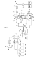
- FIG. 1 is a schematic diagram illustrating a marine diesel engine according to the first embodiment.
- FIG. 2 is a schematic diagram illustrating a marine diesel engine according to the second embodiment.
- FIG. 1 is a schematic diagram illustrating a marine diesel engine according to the first embodiment.
- the marine diesel engine 11 is, for example, a two-stroke one-cycle uniflow scavenging crosshead internal combustion engine that is used as a main engine for marine propulsion.
- the diesel engine body 12 includes a cylinder liner 13, a piston 14, a scavenging trunk 15, an exhaust manifold 16, an exhaust valve 17, and an injector (fuel injection valve) 18.
- the cylinder liner 13 is disposed in a cylinder jacket (not shown), and a cylinder cover 21 is fixed to an upper portion thereof to define a space portion.
- a piston 14 is provided in the space portion so as to be reciprocally movable along the vertical direction.
- the combustion chamber 22 is formed.
- the cylinder cover 21 is provided with an exhaust valve 17, and the exhaust valve 17 can be opened and closed by a valve gear 23.
- the combustion chamber 22 is connected to the exhaust manifold 16 via an exhaust pipe 24, and the exhaust valve 17 opens and closes the combustion chamber 22 and the exhaust pipe 24.
- the cylinder cover 21 is provided with an injector 18, and the injector 18 can inject fuel into the combustion chamber 22.
- the injector 18 is connected to a fuel tank 29 by a fuel supply pipe 25 through a fuel injection pump 26, a filter 27, and a fuel pressurization pump 28.
- the cylinder liner 13 is connected to the scavenging trunk 15 via a plurality of scavenging ports 30 provided in the lower part.
- the scavenging trunk 15 can supply air through an intake pipe (not shown).
- piston 14 the upper end part of piston rod 14a is connected with the lower end part.
- the crankshaft is rotatably supported at the lower part of the diesel engine main body 12, and the lower end portion of the connecting rod is rotatably connected via the crank.
- the diesel engine main body 12 is supported so that the crosshead can move along the vertical direction, and the crosshead is rotatably connected to the lower end of the piston rod 14a and the upper end of the connecting rod.
- the pressure in the combustion chamber 22 becomes a predetermined compression pressure, and the injector 18 injects fuel into the combustion chamber 22. Then, air and fuel are mixed and burned in the combustion chamber 22, and the piston 14 is lowered by the combustion energy.
- the exhaust valve 17 is lowered by the valve operating device 23 and the combustion chamber 22 and the exhaust pipe 24 communicate with each other, the exhaust gas generated by the combustion is pushed out from the combustion chamber 22 to the exhaust manifold 16 through the exhaust pipe 24. Air is introduced into the combustion chamber 22 from the scavenging port 30.
- the marine diesel engine 11 has a turbocharger 31 connected to the diesel engine body 12.
- the supercharger 31 is configured by connecting a compressor (compressor) 32 and a turbine 33 on the same axis via a rotating shaft 34. Therefore, the compressor 32 and the turbine 33 can rotate integrally with the rotating shaft 34.
- the compressor 32 is connected to an intake pipe L1 for intake air from the outside, and is connected to an air conduit L2 leading to the scavenging trunk 15, and an air cooler 37 is provided in the air conduit L2.
- the turbine 33 is connected to an exhaust pipe L3 from the exhaust manifold 16 and to an exhaust pipe L4 that exhausts to the outside.
- the exhaust pipe L4 is connected to the chimney 35.
- the chimney 35 discharges the exhaust gas whose temperature has been reduced by driving the turbine 33 and whose temperature has decreased. That is, the supercharger 31 releases the exhaust gas that has driven the turbine 33 from the chimney 35 to the atmosphere without recovering heat through the exhaust pipe L4.
- the marine diesel engine 11 includes a turbocharger 31 including a diesel engine main body 12, a compressor 32, and a turbine 33, an injector 18, a fuel supply pipe 25, a fuel injection pump 26, a filter 27, and fuel.
- a fuel supply system 36 including a pressurizing pump 28 and a fuel tank 29 is provided. The fuel supply system 36 supplies only low-sulfur distillate oil as fuel to the diesel engine main body 12.
- This low-sulfur distillate is, for example, a distillate defined as DMX grade, DMA grade, DMZ grade, and DMB grade defined by ISO 8217. That is, the low sulfur distillate preferably contains 0.5% or less of the sulfur component, and optimally 0.1% or less. And this low-sulfur distillate has an extremely low viscosity compared with C heavy oil, and it is min in ISO 8217 DMA class. It is 2.0 cSt at 40 ° C. (max. 6.0 cSt at 40 ° C.). Therefore, the fuel supply system 36 does not require a heating device for heating the fuel, and supplies the low-temperature distillate oil at normal temperature (non-heated state) to the diesel engine body 12.
- the supercharger 31 recovers the thermal energy of the exhaust gas when the turbine 33 is driven by the exhaust gas discharged from the diesel engine body 12.
- the heat recovery amount of the exhaust gas can be increased by increasing the efficiency of the compressor 32 and the turbine 33 or applying a multistage supercharger.
- low sulfur distillate oil is stored as fuel in the fuel tank 29, and when the fuel pressurization pump 28 is driven, the low sulfur distillate oil in the fuel tank 29 is pressurized to a predetermined pressure and fuel is supplied.
- the fuel injection pump 26 is driven by being fed to the supply pipe 25, low sulfur distillate oil having a predetermined pressure is sent to the injector 18, and when the valve of the injector 18 is opened, only the low sulfur distillate oil is supplied to the diesel engine body. 12 combustion chambers 22 are injected.
- the exhaust gas discharged from the exhaust manifold 16 of the diesel engine body 12 drives the turbine 33 of the supercharger 31.
- the turbine 33 When the turbine 33 is driven to rotate, the compressor 32 integrally connected via the rotating shaft 34 is driven to rotate, and the intake air is compressed and supplied to the scavenging trunk 15.
- the exhaust gas discharged from the supercharger 31 recovers thermal energy, drops in temperature to 180 ° C. or less, and is discharged from the chimney 35 to the outside. At this time, since the exhaust gas is obtained by burning low-sulfur distillate oil, there is almost no sulfur component contained, and low-temperature corrosion of the exhaust pipe L4 is suppressed.
- the diesel engine main body 12 the fuel supply system 36 that supplies only low-sulfur distillate oil as fuel to the diesel engine main body 12, and the diesel engine main body 12 A turbine 33 that is driven by exhaust gas to recover heat, and a turbocharger 31 that includes a compressor 32 that supplies air as a combustion gas to the diesel engine main body 12 by rotating coaxially with the turbine 33.
- the turbocharger 31 can further increase the thermal energy of the exhaust gas by driving the turbine 33 with the exhaust gas. Many can be recovered. As a result, while it is possible to suppress the occurrence of low temperature corrosion, it is possible to improve the fuel consumption in the diesel engine body 12, and also to a plurality of fuel supply systems, fuel heating devices, sulfur recovery scrubbers, etc. Therefore, it is possible to reduce the size of the apparatus and the cost of the equipment.
- the turbine 33 recovers heat from the exhaust gas from the diesel engine body 12 until the temperature reaches 180 ° C. or lower. Therefore, the supercharger 31 can efficiently recover heat from the exhaust gas.
- the fuel supply system 36 supplies low-sulfur distillate oil at normal temperature (non-heated state) to the diesel engine main body 12. Accordingly, it is possible to reduce the size of the apparatus and the cost of the equipment by eliminating the need for a fuel heating apparatus.
- the marine diesel engine of the first embodiment is provided with a chimney 35 that discharges exhaust gas that has driven the turbine 33 to the atmosphere without recovering heat. Accordingly, it is possible to simplify the apparatus by eliminating the need for a heat exchanger facility.
- FIG. 2 is a schematic diagram illustrating a marine diesel engine according to the second embodiment.
- the marine diesel engine 11 includes a diesel engine body 12, a supercharger 31 including a compressor 32 and a turbine 33, an injector 18, a fuel supply pipe 25, and fuel.
- a fuel supply system 36 composed of an injection pump 26, a filter 27, a fuel pressurization pump 28 and a fuel tank 29, and a heat recovery device 41 are provided.
- the heat recovery device 41 is composed of, for example, an economizer, a boiler, an air-water separation drum, and the like, and is provided in an exhaust pipe L4 that connects the supercharger 31 and the chimney 35.
- the heat recovery device 41 is connected to a water supply pipe L11 and a steam pipe L12, and heat is supplied between the water supplied from the water supply pipe L11 and the exhaust gas from the exhaust pipe L4 to heat the water supply to generate steam. Thus, heat is recovered, and this steam is discharged from the steam pipe L12.
- This steam pipe L12 is branched into four on the downstream side, one branch pipe L13 is connected to an impurity removing device (purifier) 42 of the lubricating oil system, and one branch pipe L14 is connected to the hot water generating equipment 43, One branch pipe L15 is connected to the cargo tank 44, and one branch pipe L16 is connected to the heating facility 45 in the residential area.
- purifier impurity removing device
- the heat recovery device 41 can generate a small amount of steam, which is generated by the impurity removing device 42 and hot water. It supplies to the production
- the fuel supply system 36 supplies only low-sulfur distillate oil as fuel to the diesel engine body 12.
- the turbocharger 31 when the turbine 33 is driven by exhaust gas, the turbocharger 31 is driven and rotated by the compressor 32 to compress the intake air and supply it to the scavenging trunk 15.
- the exhaust gas discharged from the supercharger 31 recovers thermal energy, drops in temperature to 180 ° C. or lower, and is sent to the heat recovery device 41.
- the heat recovery apparatus 41 generates steam by heating the feed water supplied from the feed water pipe L11 with exhaust gas, and through the steam pipe L12, the impurity removing device 42, the hot water generating equipment 43, the cargo tank 44, and the heating equipment 45 in the residential area. Or the like to a steam operating device that requires steam.
- the exhaust gas discharged from the heat recovery device 41 is discharged from the chimney 35 to the outside. At this time, since the exhaust gas is obtained by burning low-sulfur distillate oil, there is almost no sulfur component contained, and low-temperature corrosion of the exhaust pipe L4 is suppressed.
- the diesel engine main body 12 the fuel supply system 36 that supplies only low-sulfur distillate oil as fuel to the diesel engine main body 12, and the diesel engine main body 12
- a turbocharger 31 provided with a compressor 33 for supplying air as a combustion gas to the diesel engine main body 12 by rotating coaxially with the turbine 33 driven by exhaust gas and recovering heat, and a heat recovery device 41 are provided. ing.
- the turbocharger 31 can further increase the thermal energy of the exhaust gas by driving the turbine 33 with the exhaust gas. Many can be recovered. As a result, while it is possible to suppress the occurrence of low temperature corrosion, it is possible to improve the fuel consumption in the diesel engine body 12, and also to a plurality of fuel supply systems, fuel heating devices, sulfur recovery scrubbers, etc. Therefore, it is possible to reduce the size of the apparatus and the cost of the equipment.
- the steam generated by the heat recovery device 41 requires steam from the lubricant removal system 42, the hot water generation equipment 43, the cargo tank 44, the heating equipment 45 in the residential area, and the like. Only one or more selected from the steam operating devices. Therefore, the economizer constituting the heat recovery device can be downsized by reducing the number of steam supply points.
Landscapes
- Engineering & Computer Science (AREA)
- Chemical & Material Sciences (AREA)
- Combustion & Propulsion (AREA)
- Mechanical Engineering (AREA)
- General Engineering & Computer Science (AREA)
- Ocean & Marine Engineering (AREA)
- Supercharger (AREA)
- Output Control And Ontrol Of Special Type Engine (AREA)
- Engine Equipment That Uses Special Cycles (AREA)
Abstract
Description
図1は、第1実施形態の舶用ディーゼルエンジンを表す概略図である。
図2は、第2実施形態の舶用ディーゼルエンジンを表す概略図である。
12 ディーゼルエンジン本体
13 シリンダライナ
14 ピストン
15 掃気トランク
16 排気マニホールド
17 排気弁
18 インジェクタ(燃料噴射弁)
22 燃焼室
31 過給機
32 コンプレッサ(圧縮機)
33 タービン
35 煙突
36 燃料供給系統
37 空気冷却器
41 熱回収装置
42 不純物除去装置(蒸気稼働装置)
43 温水生成設備(蒸気稼働装置)
44 カーゴタンク(蒸気稼働装置)
45 居住区の暖房設備(蒸気稼働装置)
L1 吸気管
L2 空気導管
L3,L4 排気管
L11 給水管
L12 蒸気管
Claims (4)
- ディーゼルエンジン本体と、
前記ディーゼルエンジン本体に燃料として低硫黄留出油だけを供給する燃料供給系統と、
前記ディーゼルエンジン本体からの排ガスにより駆動して熱回収するタービン及び前記タービンと同軸回転することで前記ディーゼルエンジン本体に燃焼用気体を供給する圧縮機を備え、
前記タービンは、タービン出口における前記ディーゼルエンジン本体からの排ガスの温度が180℃以下になるまで熱回収する、
ことを特徴とする舶用ディーゼルエンジン。 - 前記燃料供給系統は、前記ディーゼルエンジン本体に対して常温の低硫黄留出油を供給することを特徴とする請求項1に記載の舶用ディーゼルエンジン。
- 前記タービンを駆動した排ガスを熱回収しないで大気に放出する煙突が設けられることを特徴とする請求項1または請求項2に記載の舶用ディーゼルエンジン。
- 前記タービンを駆動した排ガスを熱回収して蒸気を生成するためのエコノマイザ、ボイラまたは気水分離ドラム等で構成される熱回収装置が設けられ、前記熱回収装置により生成された蒸気が潤滑油系統の不純物除去装置、温水生成設備、カーゴタンクまたは居住区の暖房設備等の蒸気を必要とする蒸気稼働装置から選択される1つまたは複数だけに供給されることを特徴とする請求項1から請求項3のいずれか一項に記載の舶用ディーゼルエンジン。
Priority Applications (4)
| Application Number | Priority Date | Filing Date | Title |
|---|---|---|---|
| KR1020197023641A KR20190105625A (ko) | 2017-03-03 | 2018-01-31 | 선박용 디젤 엔진 |
| KR1020217041531A KR20210157423A (ko) | 2017-03-03 | 2018-01-31 | 선박용 디젤 엔진 |
| KR1020247004024A KR20240023196A (ko) | 2017-03-03 | 2018-01-31 | 선박용 디젤 엔진 |
| CN201880012581.7A CN110325436A (zh) | 2017-03-03 | 2018-01-31 | 船舶用柴油发动机 |
Applications Claiming Priority (2)
| Application Number | Priority Date | Filing Date | Title |
|---|---|---|---|
| JP2017-040648 | 2017-03-03 | ||
| JP2017040648A JP7014518B2 (ja) | 2017-03-03 | 2017-03-03 | 舶用ディーゼルエンジン |
Publications (1)
| Publication Number | Publication Date |
|---|---|
| WO2018159203A1 true WO2018159203A1 (ja) | 2018-09-07 |
Family
ID=63371018
Family Applications (1)
| Application Number | Title | Priority Date | Filing Date |
|---|---|---|---|
| PCT/JP2018/003191 Ceased WO2018159203A1 (ja) | 2017-03-03 | 2018-01-31 | 舶用ディーゼルエンジン |
Country Status (4)
| Country | Link |
|---|---|
| JP (1) | JP7014518B2 (ja) |
| KR (3) | KR20210157423A (ja) |
| CN (1) | CN110325436A (ja) |
| WO (1) | WO2018159203A1 (ja) |
Families Citing this family (2)
| Publication number | Priority date | Publication date | Assignee | Title |
|---|---|---|---|---|
| KR102735341B1 (ko) | 2018-07-31 | 2024-11-27 | 스미토모 겐키 가부시키가이샤 | 쇼벨 |
| JP7820225B2 (ja) * | 2022-04-28 | 2026-02-25 | 川崎重工業株式会社 | 水中翼船の推進システムおよび水中翼船 |
Citations (6)
| Publication number | Priority date | Publication date | Assignee | Title |
|---|---|---|---|---|
| JP2009532614A (ja) * | 2006-04-12 | 2009-09-10 | エムエーエヌ・ディーゼル・フィリアル・アフ・エムエーエヌ・ディーゼル・エスイー・ティスクランド | エネルギー回収構成を備える大型ターボ過給型ディーゼル機関 |
| JP2012021438A (ja) * | 2010-07-13 | 2012-02-02 | Hitachi Zosen Corp | ターボチャージャー制御システム及び制御方法 |
| JP2013002355A (ja) * | 2011-06-16 | 2013-01-07 | Ihi Corp | 脱硝装置 |
| WO2013030889A1 (ja) * | 2011-08-31 | 2013-03-07 | 川崎重工業株式会社 | 熱回収ユニット、排ガスエコノマイザ及び廃熱回収システム |
| JP2013181417A (ja) * | 2012-02-29 | 2013-09-12 | Yanmar Co Ltd | 船用燃料供給システム |
| WO2016174761A1 (ja) * | 2015-04-30 | 2016-11-03 | 富士電機株式会社 | 船舶用レーザ式ガス分析計 |
Family Cites Families (4)
| Publication number | Priority date | Publication date | Assignee | Title |
|---|---|---|---|---|
| JP2007331670A (ja) | 2006-06-16 | 2007-12-27 | Oshima Shipbuilding Co Ltd | 船舶の燃料供給装置 |
| JP5683359B2 (ja) * | 2011-03-31 | 2015-03-11 | 三菱重工業株式会社 | 排熱回収発電装置 |
| DK177460B1 (en) * | 2012-04-26 | 2013-06-17 | Man Diesel & Turbo Deutschland | Propulsion system for ships with a large turbocharged two-stroke piston engine with waste heat recovery and operation of the operating system |
| JP6125415B2 (ja) * | 2013-11-27 | 2017-05-10 | 三菱重工業株式会社 | 廃熱回収システム、舶用推進システム、船舶及び廃熱回収方法 |
-
2017
- 2017-03-03 JP JP2017040648A patent/JP7014518B2/ja not_active Ceased
-
2018
- 2018-01-31 KR KR1020217041531A patent/KR20210157423A/ko not_active Ceased
- 2018-01-31 KR KR1020247004024A patent/KR20240023196A/ko not_active Ceased
- 2018-01-31 WO PCT/JP2018/003191 patent/WO2018159203A1/ja not_active Ceased
- 2018-01-31 KR KR1020197023641A patent/KR20190105625A/ko not_active Ceased
- 2018-01-31 CN CN201880012581.7A patent/CN110325436A/zh active Pending
Patent Citations (6)
| Publication number | Priority date | Publication date | Assignee | Title |
|---|---|---|---|---|
| JP2009532614A (ja) * | 2006-04-12 | 2009-09-10 | エムエーエヌ・ディーゼル・フィリアル・アフ・エムエーエヌ・ディーゼル・エスイー・ティスクランド | エネルギー回収構成を備える大型ターボ過給型ディーゼル機関 |
| JP2012021438A (ja) * | 2010-07-13 | 2012-02-02 | Hitachi Zosen Corp | ターボチャージャー制御システム及び制御方法 |
| JP2013002355A (ja) * | 2011-06-16 | 2013-01-07 | Ihi Corp | 脱硝装置 |
| WO2013030889A1 (ja) * | 2011-08-31 | 2013-03-07 | 川崎重工業株式会社 | 熱回収ユニット、排ガスエコノマイザ及び廃熱回収システム |
| JP2013181417A (ja) * | 2012-02-29 | 2013-09-12 | Yanmar Co Ltd | 船用燃料供給システム |
| WO2016174761A1 (ja) * | 2015-04-30 | 2016-11-03 | 富士電機株式会社 | 船舶用レーザ式ガス分析計 |
Also Published As
| Publication number | Publication date |
|---|---|
| JP7014518B2 (ja) | 2022-02-01 |
| JP2018144608A (ja) | 2018-09-20 |
| KR20210157423A (ko) | 2021-12-28 |
| CN110325436A (zh) | 2019-10-11 |
| KR20190105625A (ko) | 2019-09-17 |
| KR20240023196A (ko) | 2024-02-20 |
Similar Documents
| Publication | Publication Date | Title |
|---|---|---|
| JP7410216B2 (ja) | アンモニア吸収システムを有する大型2ストロークユニフロー掃気ターボ過給式内燃機関 | |
| JP5839801B2 (ja) | 2ストロークエンジンおよび4ストロークエンジン | |
| KR20170014020A (ko) | 선박 및 선박의 운용 방법 | |
| JP6122300B2 (ja) | エンジンシステム及び船舶 | |
| WO2024032899A1 (en) | A large turbocharged two-stroke uniflow crosshead internal combustion engine | |
| JP2025513431A (ja) | 大型ターボ過給式2ストロークユニフロークロスヘッド式内燃機関 | |
| WO2018159203A1 (ja) | 舶用ディーゼルエンジン | |
| CN101858240A (zh) | 具有废气洗涤器的大型二冲程柴油发动机 | |
| JP5965019B1 (ja) | 燃料供給装置 | |
| DK177616B1 (en) | Large, slow-moving, turbocharged, two-stroke internal two-stroke internal combustion engine with cross heads and steam turbine | |
| DK178962B1 (en) | A self-igniting internal combustion engine having a gaseous fuel supply system with pilot oil injection | |
| JP7475530B1 (ja) | 大型ターボ過給式2ストロークユニフロークロスヘッド内燃機関及びその動作方法 | |
| KR102437797B1 (ko) | 선박용 내연 기관 | |
| KR20220056142A (ko) | 배기가스 재순환 시스템 및 이를 구비한 선박 | |
| DK182284B1 (en) | A large dual fuel two-stroke uniflow scavenged turbocharged internal combustion engine with exhaust gas purification system for both fuels | |
| Charnews | Marine Diesel Engines | |
| Pozdneev et al. | MODERN MARINE DIESEL ENGINES | |
| Specht | Evaluation of free piston-gas turbine marine propulsion machinery in GTS William Patterson | |
| Mellanby | Clyde Marine Oil-Engines | |
| Hardy | Motorships: an investigation into the characteristics of mercantile vessels propelled by internal combustion engines | |
| Brown et al. | Marine Power Plant, 10th June: Oil Engines and Steam Engines for Marine Propulsion | |
| Schnohr | Design concept of marine GenSet engines | |
| Schmidt | High-powered diesel engines for marine propulsion | |
| Gro̸ne et al. | Enhanced Application and Emission Control Possibilities With Electronically Controlled Low Speed Diesels | |
| Kilchenmann | Slow Speed Versus High Speed Diesel Engines for Ship Propulsions |
Legal Events
| Date | Code | Title | Description |
|---|---|---|---|
| 121 | Ep: the epo has been informed by wipo that ep was designated in this application |
Ref document number: 18761864 Country of ref document: EP Kind code of ref document: A1 |
|
| ENP | Entry into the national phase |
Ref document number: 20197023641 Country of ref document: KR Kind code of ref document: A |
|
| NENP | Non-entry into the national phase |
Ref country code: DE |
|
| 122 | Ep: pct application non-entry in european phase |
Ref document number: 18761864 Country of ref document: EP Kind code of ref document: A1 |
|
| WWR | Wipo information: refused in national office |
Ref document number: 1020247004024 Country of ref document: KR |