WO2018158931A1 - 攪拌装置 - Google Patents
攪拌装置 Download PDFInfo
- Publication number
- WO2018158931A1 WO2018158931A1 PCT/JP2017/008447 JP2017008447W WO2018158931A1 WO 2018158931 A1 WO2018158931 A1 WO 2018158931A1 JP 2017008447 W JP2017008447 W JP 2017008447W WO 2018158931 A1 WO2018158931 A1 WO 2018158931A1
- Authority
- WO
- WIPO (PCT)
- Prior art keywords
- lid
- opening
- stirring blade
- container
- stirring
- Prior art date
- Legal status (The legal status is an assumption and is not a legal conclusion. Google has not performed a legal analysis and makes no representation as to the accuracy of the status listed.)
- Ceased
Links
Images








Classifications
-
- B—PERFORMING OPERATIONS; TRANSPORTING
- B01—PHYSICAL OR CHEMICAL PROCESSES OR APPARATUS IN GENERAL
- B01F—MIXING, e.g. DISSOLVING, EMULSIFYING OR DISPERSING
- B01F27/00—Mixers with rotary stirring devices in fixed receptacles; Kneaders
- B01F27/80—Mixers with rotary stirring devices in fixed receptacles; Kneaders with stirrers rotating about a substantially vertical axis
-
- B—PERFORMING OPERATIONS; TRANSPORTING
- B01—PHYSICAL OR CHEMICAL PROCESSES OR APPARATUS IN GENERAL
- B01F—MIXING, e.g. DISSOLVING, EMULSIFYING OR DISPERSING
- B01F27/00—Mixers with rotary stirring devices in fixed receptacles; Kneaders
- B01F27/80—Mixers with rotary stirring devices in fixed receptacles; Kneaders with stirrers rotating about a substantially vertical axis
- B01F27/90—Mixers with rotary stirring devices in fixed receptacles; Kneaders with stirrers rotating about a substantially vertical axis with paddles or arms
Definitions
- This invention relates to a stirrer for bone cement or the like used for medical treatment such as orthopedics and dentistry.
- the conventional slot may be integrally provided at one end to which the handle of the cylinder is attached.
- bone cement is injected through the slot after mixing (right of page 3 of Patent Document 1).
- Column see column 47, lines 49 to 49)
- the slot can be provided in another member such as a cap or a plate sandwiched between the cylinder and the lid (from the 49th line of the right column (column 6) on page 3 of Patent Document 1). (Refer to the 2nd line of the left column (column 7) on page 4.)
- the member provided with the slot is removed before the injection of the bone cement after the mixing paddle is pulled out through the slot (see the left column (column 7) on page 4 of Patent Document 1). ).
- the present invention has been made in view of the problems of the above-described conventional techniques, and an object of the present invention is to reduce the number of work steps.
- a stirrer that stirs the material is a target.
- the stirring device has the following configuration.
- (1) Container The container has an opening for storing the material and a storage chamber for storing the material put through the opening.
- Stirring blade The stirring blade is inserted into the storage chamber from the opening, and stirs the material in the storage chamber.
- Lid The lid is detachable that closes the opening.
- Operation part The operation part penetrates the lid part from the outside of the container, is connected to the stirring blade, and rotates the stirring blade in the storage chamber.
- the inner lid is provided with a passage port through which the stirred material can pass.
- a passage port through which the stirred material can pass.
- the inner lid has a facing portion (for example, an outer fitting portion) facing the outer peripheral portion of the container constituting the opening, 2ndly, between the outer peripheral part and the opposing part (for example, external fitting part), the recessed part and the convex part which fits into a recessed part are provided in each.
- the inner lid can be easily and quickly fixed to the container by providing the concave and convex portions that fit into each other between the container and the inner lid.
- a drop prevention means (for example, a protrusion) is provided between the stirring blade and the inner lid to prevent the inner lid from falling off in a state where the stirring blade is inserted into the insertion groove. Yes. According to this aspect, the falling off of the inner lid from the stirring blade can be prevented.
- a locking portion and an engaging portion locked to the locking portion are provided respectively.
- the inner lid is pressed so that the concave and convex portions are fitted to each other, so that the inner lid is fixed with a relatively light force and securely when the lid is mounted. can do.
- the present invention after stirring, when removing the stirring blade, not only can the material be scraped off by the inner lid fixed to the opening of the container, but also the inner lid can be attached when the lid is attached, Since it is not necessary to remove the inner lid when extracting the material after stirring, the number of work steps can be reduced.
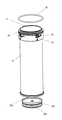
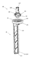
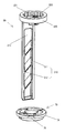
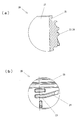
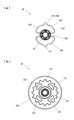
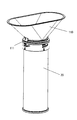
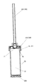
- FIG. 1 It is one disassembled perspective view of embodiment of the stirring apparatus by this invention. It is a perspective view of a container, the 1st seal member, and a bottom. It is a disassembled perspective view of a stirring blade and a connection part. It is a perspective view of an operation part, a connection part, and the 2nd and 3rd seal member. It is a perspective view of a stirring blade and an inner lid. It is for demonstrating a container, The figure (a) is a front view, (b) is sectional drawing which follows the AA line of (a). It is for demonstrating a container, The figure (a) is an enlarged view of the B section of FIG.6 (b), (b) is an enlarged view of the C section of FIG.6 (a).
- FIG. 4A is a plan view
- FIG. 4B is a sectional view taken along line EE of FIG.
- FIG. 16 is a cross-sectional view corresponding to FIG. 15 in a state where a connecting pin is pushed in. It is a longitudinal cross-sectional view of the container with which the inner lid was mounted
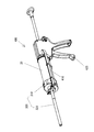
- FIG. 18 corresponds to FIG. 17 and is a half sectional perspective view. It is a longitudinal cross-sectional view of the container equipped with the nozzle. It is a perspective view of a gun.
- reference numeral 10 represents one of the embodiments of the stirring device according to the present invention, which is used for medical treatment such as orthopedics and dentistry, etc., and a material whose viscosity resistance increases when mixed (not shown, (Hereinafter also referred to as “bone cement”).
- Bone cement is composed of an acrylic resin that hardens gradually by mixing powder and liquid, that is, hardens within a few minutes after stirring. For this reason, it is necessary to complete the work in about 2 minutes after stirring until extraction to the affected area.
- “bone cement” was illustrated as a material, it is not limited to this.
- a material having viscous resistance and a material having no viscous resistance are mixed, and the viscosity resistance is not increased by stirring. As in the case of a certain material, a material having viscosity may be mixed and stirred to lower the viscosity resistance. (3) When one material is stirred, the viscosity resistance may be increased or decreased.
- the stirring device 10 is roughly composed of the following parts.
- the following (1) to (7) will be described later.
- Container 20 (2) Stirring blade 30 (3) Lid 40 (4) Operation unit 50 (5) Connecting part 60 (6) Inner lid 70 (7)
- First to third seal members 80, 90 and 100 The parts of the stirring device 10 are not limited to the above (1) to (7), and for example, the first to third seal members 80, 90 and 100 may be omitted.
- the container 20 has an opening 21 for storing bone cement and a storage chamber 22 for storing the bone cement inserted from the opening 21.
- the container 20 is formed in a cylinder shape, for example, a cylindrical shape, and has one opening surface as an opening portion 21 and the other opening surface is closed with a bottom portion 200 to be described later as shown in FIGS.
- the container 20 is integrally formed of a thermoplastic resin having sufficient strength to withstand the stirring and extraction of the bone cement by the stirring blade 30 and having chemical resistance. Further, the main body of the container 20 is integrally formed of a transparent resin so that the stirring state of the bone cement can be observed.
- the container 20 roughly includes the following parts.
- the parts of the container 20 are not limited to the following parts (1) to (3).
- the inclined part 24 can be omitted.
- Locking part 23 The locking portion 23 is intermittently formed in a rail shape on the outer periphery of the opening 21.
- the locking portion 23 is for engaging with a claw-like engaging portion 42 described later of the lid portion 40 and fixing the lid portion 40 to the opening portion 21 of the container 20.
- (2) Inclined part 24 The inclined portion 24 advances the lid 40 toward the container 20 when the lid 40 is rotated with respect to the outer peripheral portion.
- the inclined portion 24 is formed continuously with the rail-like locking portion 23, and is inclined obliquely with respect to the forward direction.
- the inclined portion 24 engages with a claw-like engaging portion 42 described later of the lid portion 40, and when the lid portion 40 is rotated, the lid portion 40 is advanced toward the container 20.
- the recess 25 is located at the outer edge of the opening 21 and is formed in an annular groove shape.
- the concave portion 25 is for fixing the inner lid 70 to the opening 21 of the container 20 by elastically fitting a claw-like convex portion 75 described later of the inner lid 70 shown in FIG.
- the stirring blade 30 As shown in FIGS. 3, 13, and 15, the stirring blade 30 is inserted into the storage chamber 22 through the opening 21 and stirs the bone cement in the storage chamber 22.
- the stirring blade 30 is formed integrally with a thermoplastic resin having sufficient strength to withstand the stirring of the bone cement and having chemical resistance. As shown in FIG. 3, the stirring blade 30 is roughly composed of the following parts. The following (1) and (2) will be described later. (1) Wing body 210 (2) Receiver 220
- the lid 40 is detachable for closing the opening 21 of the container 20.
- the lid 40 is formed in a cap shape that can be put on the outer periphery of the opening 21 of the container 20. Similar to the container 20, the lid 40 has chemical resistance and is integrally formed of a transparent resin so that the stirring state of the bone cement can be observed from above.
- the lid part 40 has the following parts.
- (1) Through hole 41 The through hole 41 is located in the center of the upper surface of the lid portion 40, penetrates up and down, and is formed in a circular shape.
- a connection pin 260 (described later) of the operation unit 50 passes through the through hole 41, and the operation unit 50 and the connection unit 60 are connected through the through hole 41.
- (2) Engaging portion 42 The engaging portion 42 is formed in a claw shape on the inner peripheral surface of the skirt portion of the lid portion 40. The engaging portion 42 is for engaging with a rail-shaped locking portion 23 formed on the container 20 and fixing the lid portion 40 to the opening portion 21 of the container 20.
- the engaging part 42 engages with the inclined part 24 protruding from the outer periphery when the cover part 40 is put on the outer periphery of the opening part 21 of the container 20 and the cover part 40 is rotated clockwise.
- the engaging portion 42 moves while contacting the lower edge of the inclined portion 24, thereby moving the lid portion 40 forward toward the container 20.
- the engaging part 42 reaches the substantially horizontal engaging part 23 that continues to the inclined part 24, and the engaging part 23 is located immediately above, so that the cover part 40 is prevented from coming off. Is done.
- the claw-like engagement portion 42 is provided on the lid portion 40, and the rail-like engagement portion 23 is provided on the container 20, but not limited thereto, the lid portion 40 is provided with a rail-like engagement portion,
- the container 20 may be provided with a claw-shaped engaging portion, and the engaging portion 42 is not limited to a claw shape, and the locking portion 23 is not limited to a rail shape.
- Exhaust port 43 extends in a cylindrical shape laterally from the upper part of the lid part 40 and communicates with the inside and outside.
- a pipe is connected to the exhaust port 43, and the pipe is connected to a decompression pump.
- the decompression pump is for decompressing the inside of the container 20.
- the agitator 10 has a structure in which the inside of the container 20 is sealed and agitated while reducing the pressure for the purpose of removing bubbles and by-product organic gas in the bone cement.
- the operation unit 50 is connected to the stirring blade 30 through the lid 40 from the outside of the container 20, and rotates the stirring blade 30 in the storage chamber 22. Is. As shown in FIG. 4, the operation unit 50 is roughly composed of the following parts. The following (1) to (3) will be described later. (1) Arm 250 (2) Connecting pin 260 (3) Handle 270
- connection part 60 As shown in FIGS. 3, 4, and 15, the connecting portion 60 is located between the stirring blade 30 and the operation portion 50, and transmits the power of the operation portion 50 to the blade body 210 of the stirring blade 30. is there.
- the connecting portion 60 is integrally formed of a thermoplastic resin having appropriate elasticity and rigidity and having chemical resistance. As shown in FIG. 3, the connecting part 60 is roughly composed of the following parts. The following (1) and (2) will be described later. (1) Tube part 230 (2) Ratchet 240
- the inner lid 70 is located between the lid 40 and the opening 21 and has an insertion groove 71 through which the stirring blade 30 can be inserted.
- the stirring blade 30 is inserted into the storage chamber 22 in a state where the stirring blade 30 is passed through the insertion groove 71, and the lid 40 is fixed to the opening 21 when the lid 40 is attached to the opening 21. Is removed from the opening 21, and when the stirring blade 30 is pulled out of the storage chamber 22, the bone cement adhering to the stirring blade 30 is scraped off.
- the inner lid 70 is integrally formed of a thermoplastic resin having appropriate elasticity and rigidity and having chemical resistance.
- the inner lid 70 is formed in a disk shape having an outer diameter equal to or smaller than the inner diameter of the opening 21 of the container 20 and fits into the opening 21.
- the inner lid 70 has the following parts when roughly classified.
- Insertion groove 71 The insertion groove 71 penetrates up and down and allows the stirring blade 30 to pierce.
- the insertion groove 71 is located in the center, and is composed of a circular portion through which a shaft portion 211 (described later) of the stirring blade 30 passes, and a thin groove portion that communicates with the circular portion and through which a blade portion 212 (described later) of the stirring blade 30 passes.
- the outer diameter and the width are substantially equal to the cross-sectional shapes of the shaft portion 211 and the wing portion 212.
- (2) Frame 72 The frame portion 72 borders the insertion groove 71 and comes into contact with the bone cement adhering to the periphery of the stirring blade 30 to scrape off the bone cement.
- Passage 73 allows the bone cement after stirring to pass after extraction of the stirring blade 30 from the insertion groove 71 during extraction.
- a pair of passage openings 73 are formed adjacent to the insertion groove 71 and are formed in a fan-shaped hole shape penetrating vertically. Note that when the bone cement passes through the passage port 73, the bone cement also passes through the insertion groove 71.
- Outer fitting part 74 The outer fitting portion 74 has a larger diameter than the inner diameter of the opening portion 21 of the container 20 and is formed in a skirt shape that projects in an annular shape from the upper surface of the inner lid 70 and is fitted on the outer periphery of the opening portion 21.
- the outer fitting portion 74 functions as a facing portion that faces the outer peripheral portion of the container 20 constituting the opening 21.
- Convex part 75 The convex portion 75 is located in the outer fitting portion 74, is formed in an annular groove shape on the outer edge portion of the opening portion 21, is fitted into the concave portion 25 elastically, and fixes the inner lid 70 in the opening portion 21. .
- the convex portions 75 are formed in a claw shape that elastically fits into the annular groove-shaped concave portion 25 due to the elasticity of the resin, and a plurality of convex portions 75, for example, a total of three are provided at 120 degree intervals.
- the inner lid 70 is fixed to the opening 21 of the container 20 and supported rotatably in the opening 21 of the container 20 with the claw-shaped protrusion 75 fitted in the annular groove-shaped recess 25. Is done.
- the inner lid 70 rotates integrally with the stirring blade 30.
- the convex portion 75 is configured to elastically fit into the concave portion 25, the present invention is not limited thereto, and for example, a structure that fits in a sliding manner without having “elasticity” may be employed.
- the inner lid 70 is provided with a claw-like convex portion 75 and the container 20 is provided with a groove-like concave portion 25.
- the present invention is not limited thereto, and the inner lid 70 is provided with a groove-like concave portion and the container 20 is provided with a claw-like concave portion.
- the convex portion 75 is not limited to a claw shape, and the concave portion 25 is not limited to a groove shape.
- the inner lid 70 is configured to be rotatable integrally with the stirring blade 30, but is not limited to this, for example, by making the cross-sectional shape of the portion of the stirring blade 30 passing through the insertion groove 71 circular, It is good also as a structure which 70 does not need to rotate.
- first to third seal members 80, 90 and 100 As shown in FIGS. 2 and 15, the first seal member 80 seals between the opening 21 and the lid 40 of the container 20, and a rubber O-ring is used. As shown in FIGS. 4 and 15, the second seal member 90 seals between the through hole 41 of the lid portion 40 and a cylinder portion 230 described later of the connecting portion 60, and a rubber O-ring is provided. in use.
- the third seal member 100 seals between the through hole 41 of the lid portion 40 and a connecting pin 260 (described later) of the operation portion 50, and a rubber O-ring is used.
- the bottom 200 As shown in FIGS. 2, 15, 17, and 18, the bottom portion 200 closes the open bottom surface of the container 20.
- the bottom 200 is a so-called piston that is inserted from the open bottom surface of the container 20 and can move in the storage chamber 22 of the container 20 from the bottom surface toward the opening 21, and pushes the bone cement after stirring from the opening 21.
- the bottom portion 200 is formed in a substantially disc shape, and is integrally formed of a thermoplastic resin having appropriate elasticity and rigidity and having chemical resistance.
- the bottom 200 is roughly composed of the following parts.
- Bearing part 201 The bearing portion 201 is located at the center of the circular inner surface facing the storage chamber 22, and is recessed in a cylindrical shape. A tip end portion of a shaft portion 211 (described later) of the stirring blade 30 is fitted into the bearing portion 201, and the stirring blade 30 turns around the bearing portion 201.
- Annular edge 202 The annular edge portion 202 protrudes from the outer periphery of the bottom portion 200 into an annular fin shape having a diameter larger than the inner diameter of the storage chamber 22. The annular edge 202 elastically contacts the inner periphery of the storage chamber 22, seals the open bottom surface of the container 20, and moves in the storage chamber 22 while maintaining the sealed state.
- the wing body 210 is located in the storage chamber 22 of the container 20 and agitates bone cement in the storage chamber (22).
- the wing body 210 is roughly composed of the following parts.
- Shaft 211 The shaft portion 211 is positioned at the center of the wing body 210 and extends in a columnar shape in the full length direction of the storage chamber 22 of the container 20.
- the shaft portion 211 has a distal end portion fitted in the bearing portion 201 of the bottom portion 200 and is held so as to be rotatable in the storage chamber 22 around the bearing portion 201.
- Wing 212 The wing portion 212 extends radially from the shaft portion 211 and is formed in a plate shape, and turns around the shaft portion 211 in the storage chamber 22.
- Notch 213 The notch 213 penetrates in the front and back direction of the plate-like wing part 212, and a plurality of notches are provided at a predetermined interval in the full length direction of the storage chamber 22 of the container 20, and are formed in a substantially rectangular shape.
- the notch 213 allows passage of the bone cement when the bone cement is agitated, and distributes the load on the wing body 210. Note that the notch 213 may be omitted.
- (4) Projection 214 The protrusion 214 prevents the inner lid 70 from falling off when the stirring blade 30 is inserted into the insertion groove 71 of the inner lid 70, and constitutes a drop-off preventing means. As shown in FIG.
- the protrusion 214 is located above the wing body 210 and protrudes in a hemispherical shape.
- the protrusion 214 is exemplified as the drop-off preventing means, but is not limited thereto, and for example, a frictional resistance between the outer surface of the stirring blade 30 and the inner surface of the insertion groove 71 of the inner lid 70 may be used.
- a clip-like elastic piece may be provided on one of the stirring blade 30 and the inner lid 70 so that the inner lid 70 is prevented from falling off by the elastic piece.
- the protrusion 214 protrudes from the wing body 210, the present invention is not limited to this.
- a protrusion may be formed in the insertion groove 71 of the inner lid 70, and the shape of the protrusion 214 is a hemisphere. Although the shape is illustrated, it may be formed in a block shape such as a cube.
- the receiving part 220 is located at one end of the wing body 210 and is connected to the operating part 50 via the connecting part 60.
- the receiving part 220 is formed in a flat ring shape having an open upper surface and a closed bottom.
- the receiving unit 220 is roughly composed of the following units.
- Internal teeth 221 The internal teeth 221 are located on a ring-shaped inner peripheral surface and are formed in a triangular concave-convex internal gear shape. The internal teeth 221 are used to transmit the power of the operation unit 50 by engaging a pawl portion 241 (described later) of the ratchet 240 from the inner peripheral side.
- the direct connection portion 222 is located at the center of the circular bottom of the receiving portion 220 and is recessed in a cylindrical shape. In the direct connection portion 222, longitudinal grooves extending in the depth direction are formed in the inner peripheral surface at predetermined intervals in the inner peripheral direction. As shown in FIG. 16, the operating portion 50 is directly connected to the stirring blade 30 via the connecting pin 260 by fitting the tip of the shaft portion of the direct connecting portion 222 into the direct connecting portion 222.
- Vent 223 The vent hole 223 penetrates the bottom of the receiving part 220 up and down, and allows air bubbles and by-product organic gas in the bone cement in the container 200 to flow.
- the vent holes 223 are formed in a substantially arc shape, and a plurality of, for example, a total of four vent holes are provided at intervals of 90 degrees.
- cylindrical portion 230 As shown in FIGS. 3, 4, 9 (a), and 15, the cylindrical portion 230 is located on the upper side of the connecting portion 60 and is formed in a cylindrical shape penetrating vertically.
- the cylindrical portion 230 has an outer diameter set to be equal to or smaller than the inner diameter of the through hole 41 of the lid portion 40, protrudes to the outside through the through hole 41, and is connected to an arm 250 (to be described later) of the operation portion 50.
- the cylindrical portion 230 has the following portions.
- Center hole 231 The center hole 231 is formed in a non-circular shape, for example, a square inscribed in the circular through hole 41 of the lid portion 40.
- a connecting pin 260 (described later) of the operation unit 50 is fitted into the center hole 231 through the through hole 41 of the lid unit 40, and the power of the operation unit 50 is transmitted.
- the ratchet 240 includes a pawl portion 241 that engages with the internal teeth 221 of the stirring blade 30, and In addition to being transmitted to the stirring blade 30, when the bone cement exceeds a predetermined viscous resistance due to stirring, the transmission of power is cut off.
- the ratchet 240 is formed in a leaf spring shape projecting from the outer periphery of the cylindrical portion 230 into a substantially C-shaped plane, and is formed as a pair separated from each other in the diameter direction of the cylindrical portion 230.
- the ratchet 240 has the following parts.
- Pawl 241 The pawl portion 241 is formed in an arc shape that protrudes from the center of the substantially C-shaped plane and fits into one of the internal teeth 221 of the stirring blade 30.
- the pawl portion 241 is formed in an arc shape so that it can easily idle and generate a click feeling and a clicking sound with respect to the triangular uneven inner teeth 221.
- the elastic deformation portions 242 are located on both sides of the pawl portion 241 and each end portion is connected to the outer periphery of the cylindrical portion 230 in an arm shape.
- the elastic deformation part 242 is formed in a plate shape, and elastically protrudes the pawl part 241 toward one of the internal teeth 221 of the stirring blade 30 using the elasticity of the resin. That is, when the bone cement exceeds a predetermined viscous resistance by stirring, the rotational resistance of the stirring blade 30 is increased, and the elastic deformation portion 242 is set to bend against the rotational resistance.
- the bulging part 243 projects in a semicircular shape from the inner surface of the elastic deformation portion 242 facing the outer peripheral surface of the cylindrical portion 230. When the elastic deformation portion 242 is bent more than necessary, the bulging portion 243 is brought into contact with the outer peripheral surface of the cylindrical portion 230 to prevent the ratchet 240 from being damaged.
- the arm 250 is formed in a horizontally long plate shape, and is non-rotatably connected to the connecting portion 60 via a connecting pin 260 at one end and a handle at the other end. 270 is rotatably supported.
- the arm 250 is integrally formed of a resin having an appropriate rigidity.
- the arm 250 has the following parts as shown in FIGS. (1) Pin holder 251
- the pin receiver 251 is located at one end of the arm 250 and penetrates up and down in a non-circular shape.
- the distal end portion of the cylindrical portion 230 of the connecting portion 60 that protrudes outside through the through hole 41 of the lid portion 40 is elastically fitted from below and cannot be removed.
- the shaft portion of the connecting pin 260 is inserted from the upper side through the center hole 231 of the cylindrical portion 230 fitted in the pin receiver 251.
- Handle receiver 252 The handle receiver 252 is located at the other end of the arm 250 and penetrates in a circular shape up and down.
- the handle 252 is supported rotatably so that the shaft portion of the handle 270 fits in from the upper side and cannot be removed.
- the connecting pin 260 is inserted from the pin receiver 251 of the arm 250 and communicates the arm 250 and the connecting portion 60 in a non-rotatable manner.
- the connecting pin 260 is integrally formed of a resin having an appropriate rigidity.
- the connecting pin 260 includes a head having an outer shape larger than the inner shape of the central hole 231 of the cylindrical portion 230 of the connecting portion 60, and a shaft having an outer shape that is suspended from the head and conforms to the inner shape of the square central hole 231 It consists of a part.
- the shaft portion is formed in a square cross section adapted to the inner shape of the center hole 231 and rotates integrally with the connecting portion 60. As shown in FIG.
- the distal end portion of the shaft portion protrudes toward the stirring blade 30 when being pushed into the center hole 231.
- An outer tooth that engages with a longitudinal groove formed on the inner periphery of the direct coupling portion 222 of the stirring blade 30 is formed at the protruding tip portion of the shaft portion, and when the connecting pin 260 is pushed in, the operation portion 50 and the stirring blade Connect 30 directly.
- the handle 270 is inserted from the handle receiver 252 of the arm 250 and is rotatably supported by the arm 250.
- the handle 270 is integrally formed of a resin having an appropriate rigidity.
- the handle 270 has a larger diameter than the inner diameter of the handle receiver 252 and is composed of a head that can be picked up by a finger and a shaft portion that hangs down from the head and has an outer diameter equal to or smaller than the inner diameter of the handle receiver 252.
- the shaft is formed in a cylindrical shape, cut from the lower end, passes through the cylindrical handle receiver 252 of the arm 250, and can be rotated with one touch to the handle receiver 252 by expanding the diameter after passing. Supported by
- the funnel 110 is for charging powder and liquid agent, which are bone cement materials, into the storage chamber 22 from the opening 21 of the container 20.
- the funnel 110 is integrally formed of a thermoplastic resin having chemical resistance.
- the funnel 110 is provided with a pair of attachment portions 111 that are inserted into the annular groove on the outer periphery of the opening 21 around the opening 21 of the container 20 inserted into the opening 21 of the container 20 in the shape of the truncated cone. .
- the lid unit 120 has a stirring blade 30, an operation unit 50, a connecting unit 60, an inner lid 70, a second lid, a second, Three seal members 90 and 100 are assembled in advance.
- the blade main body 210 of the stirring blade 30 is inserted from the tip portion in accordance with the insertion groove 71 of the inner lid 70.
- the inner lid 70 is slid toward the receiving portion 220 along the wing body 210. In the middle of the slide, the protrusion 214 (falling prevention means) of the wing body 210 and the frame portion 72 that borders the insertion groove 71 abut.
- the insertion groove 71 is expanded by being pushed by the protruding portion 214 and is restored by overcoming the protruding portion 214, so that the inner lid 70 does not fall out of the wing body 210.
- the ratchet 240 of the connecting portion 60 is fitted into the receiving portion 220 of the stirring blade 30, and the inner teeth 221 of the receiving portion 220 and the pawl portions 241 of the ratchet 240 are engaged.
- a second seal member 90 is attached to the cylindrical portion 230 of the connecting portion 60, and is inserted from the inside of the lid portion 40 along the through hole 41, and partially protrudes from the through hole 41.
- the operation unit 50 is assembled by inserting the shaft portion of the handle 270 in accordance with the handle receiver 252 of the arm 250.
- the cylindrical portion 230 of the connecting portion 60 partially protruding from the through hole 41 of the lid portion 40 is inserted from the lower side according to the pin receiver 251 of the arm 250.
- the third seal member 100 is attached to the connection pin 260 and the connection pin 260 is inserted from above in accordance with the center hole 231 of the tube portion 230 of the connection portion 60 located in the pin receiver 251 of the arm 250.
- the operation part 50 and the connection part 60 are connected through the through-hole 41 of the cover part 40, and also the stirring blade 30, the inner cover 70, and the second and third seal members 90 and 100 are attached to form the cover unit 120. .
- FIGS. 15, 17, and 18 Assembly of container 20
- the container 20 is sealed by inserting a bottom portion 200 inside the container 20 according to the open bottom surface.
- a first seal member 80 is attached to the outer periphery of the opening 21 of the container 20.
- Nozzle 300 shown in FIG. 19 The nozzle 300 is attached to the opening 21 of the container 20 as shown in FIGS. 19 and 20 after the bone cement is stirred and the lid unit 120 excluding the inner lid 70 is removed. Used for extraction.
- the nozzle 300 includes the following parts when roughly classified.
- Cap 310 The cap 310 can be screwed and fixed to the outer periphery of the opening 21 of the container 20, similarly to the lid 40.
- the cap 310 is integrally formed of a thermoplastic resin having chemical resistance.
- Nozzle body 320 The nozzle body 320 is attached to the cap 310, extends in a straw shape, and extracts the bone cement after stirring from the container 20 to the outside. Similar to the cap 310, the nozzle body 320 is integrally formed of a thermoplastic resin having chemical resistance.
- the gun 400 is used to push out the bone cement in the container 20 toward the affected part (not shown) during the operation by loading the container 20 with the nozzle 300 attached thereto. is there.
- the gun 400 has a holding portion 410 that holds the container 20 with the nozzle 300 attached thereto, and a lever that pushes the bone cement after stirring in the storage chamber 22 from the nozzle 300 by pushing the piston-shaped bottom portion 200 into the container 20. 420.
- the lid 40 of the lid unit 120 shown in FIG. 13 is attached from the opening 21 side of the container 20, and the opening 21 is sealed.
- the claw-like engaging part 42 engages with the rail-like locking part 23 located on the outer periphery of the opening 21 of the container 20.
- the claw-like engaging part 42 of the lid part 40 engages with the inclined part 24 that is a part of the rail-like locking part 23 of the container 20, and the lid part 40 faces the container 20. And move forward.
- the ceiling surface inside the lid portion 40 functions as a pressing portion that pushes the inner lid 70 into the opening 21 of the container 20.
- the inner lid 70 is fitted into the opening 21 of the container 20, and at this time, the claw-like convex portion 75 of the inner lid 70 is formed in an annular groove shape on the outer edge portion of the opening 21, and is formed in the concave portion 25.
- the inner lid 70 is fixed in the opening 21 by being elastically fitted.
- the claw-like convex portion 75 can make a clicking sound in the groove-like concave portion 25, and can give a click feeling to the operator who screws the lid portion 40, giving a sense of moderation.
- the claw-like engaging portion 42 of the lid portion 40 is locked to the rail-like engaging portion 23 located on the outer periphery of the opening 21 of the container 20, and the lid portion 40 is fixed to the container 20.
- the operation unit 50 may be swung while the container 20 is held so as not to rotate. At this time, a pipe connected to a decompression pump (not shown) is connected to the exhaust port 43 of the lid 40 to decompress the inside of the container 20.
- a pipe connected to a decompression pump (not shown) is connected to the exhaust port 43 of the lid 40 to decompress the inside of the container 20.
- the stirring blade 30 is swung in the storage chamber 22 of the container 20 through the connecting unit 60 to stir the bone cement.
- the inner lid 70 rotates integrally with the stirring blade 30.
- the locked state is released when the lid 40 is further turned.
- the inner lid 70 remains fixed in the opening 21 of the container 20.
- the blade body 210 of the stirring blade 30 is raised while passing through the insertion groove 71 of the inner lid 70 fixed in the opening 21 of the container 20.
- the stirring blade 30 is formed in the frame portion 72 that borders the periphery thereof. The bone cement adhering to the surroundings contacts and the bone cement is scraped off.
- the lid 40 is collected as a lid unit 120 shown in FIG. At this time, the inner lid 70 remains fixed in the opening 21 of the container 20.
- a nozzle 300 is mounted on the outer periphery of the opening 21 of the container 20 from which the lid 40 has been removed, as shown in FIG. 19, and then, as shown in FIG. To load.
- the piston-shaped bottom 200 is pushed into the container 20 by operating the lever 420 of the gun 400.
- the bone cement in the container 20 passes through the insertion groove 71 and the passage port 73 of the inner lid 70, and is pushed out and extracted toward the affected part (not shown) during the operation through the nozzle 300. .
- the operation unit 50 and the stirring blade 30 can be directly connected by pushing the connecting pin 260 toward the container 20. That is, when the connecting pin 260 is pushed in, the tip portion of the shaft portion fits into the direct connection portion 222 of the stirring blade 30. For this reason, the operating portion 50 and the stirring blade 30 are rotated integrally by engaging the external teeth at the tip of the connecting pin 260 and the vertical groove formed in the inner periphery of the direct connecting portion 222.
- the ratchet 240 of the part 60 stops functioning.
- An operator who rotates the operation unit 50 can freely set the hardness of the bone cement according to the rotation amount and time of the operation unit 50, and is particularly suitable when the hardness is higher than the set hardness.
Landscapes
- Chemical & Material Sciences (AREA)
- Chemical Kinetics & Catalysis (AREA)
- Mixers Of The Rotary Stirring Type (AREA)
- Accessories For Mixers (AREA)
Abstract
材料を攪拌する攪拌装置において、容器、攪拌翼、蓋部、操作部と、を備え、蓋部と開口部との間には、攪拌翼を刺し通せる挿通溝を有し、当該挿通溝に攪拌翼を通した状態で、攪拌翼を収納室内に挿入し、蓋部を開口部に装着した際に開口部に固定され、蓋部を開口部から外し、攪拌翼を収納室から引き抜く際に、攪拌翼に付着した材料をそぎ落とす中蓋を備えている。
Description
この発明は、例えば整形外科や歯科等の医療に用いられる骨セメント等の攪拌装置に関する。
従来、スロットを備えたカバーが、シリンダと蓋との間に設けられ、スロットの開口をシャフトが貫通する形にされた「骨セメント混合装置」が知られている(特許文献1の6頁の左欄(11欄)の2~5行参照)。
上記従来のスロットの幅は、ブレードの厚みと実質的に等しいので、ブレードの表面上に付着したセメントはぬぐい取られることになる(特許文献1の6頁の左欄(11欄)の8~12行参照)。
上記従来のスロットの幅は、ブレードの厚みと実質的に等しいので、ブレードの表面上に付着したセメントはぬぐい取られることになる(特許文献1の6頁の左欄(11欄)の8~12行参照)。
上記従来のスロットは、シリンダのハンドルが取着される方の一端に一体的に設けられてもよく、この場合、混合の後にスロットを通して骨セメントが射出される(特許文献1の3頁の右欄(6欄)の47~49行参照)。別の形態として、スロットを、シリンダと蓋との間に挟み込まれるキャップ、プレート等の別の部材に設けることも可能である(特許文献1の3頁の右欄(6欄)の49行~4頁の左欄(7欄)の2行参照)。この場合、スロットを備えた部材は、混合パドルがスロットを通して引き抜かれた後、骨セメントの射出を行う前に取り外される(特許文献1の4頁の左欄(7欄)の2~4行参照)。
しかし、上記した従来の「骨セメント混合装置」では、スロットをシリンダのハンドルが取着される方の一端に一体的に設けた場合に、混合の後にスロットを通して骨セメントが射出されるため、骨セメントの射出量が減少したり、抵抗が大きくなり、射出の効率が低下し、迅速な射出が困難であるばかりでなく、又、シリンダの構造が複雑化するという問題点があった。
また、従来の「骨セメント混合装置」では、別の形態として、スロットを、シリンダと蓋との間に挟み込まれるキャップ、プレート等の別の部材に設けた場合に、スロットを備えた部材は、混合パドルがスロットを通して引き抜かれた後、骨セメントの射出を行う前に取り外さなければならず、スロットの取り外し作業が必要なため、迅速な射出が困難であるという別の問題点があった。
そこで、本発明は、上記した従来の技術の有する問題点に鑑みてなされたものであり、その目的は、作業工数を低減することができるようにしたことにある。
そこで、本発明は、上記した従来の技術の有する問題点に鑑みてなされたものであり、その目的は、作業工数を低減することができるようにしたことにある。
本発明は、上記した目的を達成するためになされたものであり、本発明は、次の点を特徴とする。
第1に、材料を攪拌する攪拌装置を対象とする。
第2に、攪拌装置には、次の構成を備える。
(1)容器
容器は、材料を入れる開口部及び当該開口部から入れた材料を収納する収納室を有するものである。
(2)攪拌翼
攪拌翼は、開口部から収納室内に挿入され、当該収納室内で材料を攪拌するものである。
(3)蓋部
蓋部は、開口部を閉じる着脱可能なものである。
(4)操作部
操作部は、容器の外部から蓋部を貫通して攪拌翼に連結され、攪拌翼を収納室内で回転させるためのものである。
第3に、蓋部と開口部との間には、攪拌翼を刺し通せる挿通溝を有し、当該挿通溝に攪拌翼を通した状態で、攪拌翼を収納室内に挿入し、蓋部を開口部に装着した際に開口部に固定され、蓋部を開口部から外し、攪拌翼を収納室から引き抜く際に、攪拌翼に付着した材料をそぎ落とす中蓋を備える。
第1に、材料を攪拌する攪拌装置を対象とする。
第2に、攪拌装置には、次の構成を備える。
(1)容器
容器は、材料を入れる開口部及び当該開口部から入れた材料を収納する収納室を有するものである。
(2)攪拌翼
攪拌翼は、開口部から収納室内に挿入され、当該収納室内で材料を攪拌するものである。
(3)蓋部
蓋部は、開口部を閉じる着脱可能なものである。
(4)操作部
操作部は、容器の外部から蓋部を貫通して攪拌翼に連結され、攪拌翼を収納室内で回転させるためのものである。
第3に、蓋部と開口部との間には、攪拌翼を刺し通せる挿通溝を有し、当該挿通溝に攪拌翼を通した状態で、攪拌翼を収納室内に挿入し、蓋部を開口部に装着した際に開口部に固定され、蓋部を開口部から外し、攪拌翼を収納室から引き抜く際に、攪拌翼に付着した材料をそぎ落とす中蓋を備える。
本発明の態様の一つでは、中蓋には、攪拌後の材料が通過可能な通過口を設けている。この態様によれば、中蓋に挿通溝のほか、攪拌後の材料が通過可能な通過口を設けることで、材料の抽出時の効率の低下を防止することができる。
本発明の態様の一つでは、
第1に、中蓋には、開口部を構成する容器の外周部と対向する対向部(例えば外嵌部)を有し、
第2に、外周部と対向部(例えば外嵌部)との間には、凹部と、凹部にはまり合う凸部とをそれぞれに設けている。
この態様によれば、容器と中蓋との間に互いにはまり合う凹凸部を設けることで、中蓋を容器に簡便に且つ迅速に固定することができる。
第1に、中蓋には、開口部を構成する容器の外周部と対向する対向部(例えば外嵌部)を有し、
第2に、外周部と対向部(例えば外嵌部)との間には、凹部と、凹部にはまり合う凸部とをそれぞれに設けている。
この態様によれば、容器と中蓋との間に互いにはまり合う凹凸部を設けることで、中蓋を容器に簡便に且つ迅速に固定することができる。
本発明の態様の一つでは、攪拌翼と中蓋との間には、攪拌翼を挿通溝に刺し通した状態において、中蓋の抜け落ちを防止する抜け落ち防止手段(例えば突起部)を設けている。この態様によれば、攪拌翼からの中蓋の抜け落ちを防止することができる。
本発明の態様の一つでは、
第1に、蓋部と外周部との間には、係止部と、係止部に係止される係合部とをそれぞれに設け、
第2に、係止部と係合部との間には、外周部に対して蓋部を回転した際に、蓋部を容器に向かって前進させる傾斜部を設け、
第3に、蓋部と中蓋との間には、傾斜部により蓋部が前進する際に、凹部に凸部がはまり合うように押圧する押圧部(蓋部の内部の天井面)を設けている。
この態様によれば、蓋部を回転した際に中蓋を押圧し、凹凸部が相互にはまり合うようにできるので、蓋部の装着時に、中蓋を比較的に軽い力で且つ確実に固定することができる。
第1に、蓋部と外周部との間には、係止部と、係止部に係止される係合部とをそれぞれに設け、
第2に、係止部と係合部との間には、外周部に対して蓋部を回転した際に、蓋部を容器に向かって前進させる傾斜部を設け、
第3に、蓋部と中蓋との間には、傾斜部により蓋部が前進する際に、凹部に凸部がはまり合うように押圧する押圧部(蓋部の内部の天井面)を設けている。
この態様によれば、蓋部を回転した際に中蓋を押圧し、凹凸部が相互にはまり合うようにできるので、蓋部の装着時に、中蓋を比較的に軽い力で且つ確実に固定することができる。
本発明によれば、攪拌後、攪拌翼の取り外し時に、容器の開口部に固定された中蓋により、材料をそぎ落とすことができるばかりでなく、蓋部の装着時に中蓋を装着でき、しかも攪拌後の材料の抽出時に中蓋の取り外しが不要であるので、作業工数を低減することができる。
(攪拌装置10)
図1及び図15中、符号10は、本発明による攪拌装置の実施形態の一つを示し、例えば整形外科や歯科等の医療に用いられ、混合すると粘性抵抗が上昇する材料(図示せず、以下「骨セメント」ともいう。)を攪拌するためのものである。骨セメントは、粉末と液剤を混ぜることで徐々に硬化、すなわち攪拌後、数分で硬化するアクリル樹脂から構成されている。このため、患部への抽出迄に、攪拌後、2分程度で作業を完了する必要がある。
なお、材料として、「骨セメント」を例示したが、これに限定されない。また、材料の用途として、整形外科や歯科等の医療を例示したが、これに限定されず、食品やセメント業界等に用いるものであってもよい。さらに、材料は、粘性を有するものであれば足り、(1)元々、粘性抵抗の有る材料と粘性抵抗の無い材料とを混合し、攪拌により粘性抵抗の上昇が無いもの、(2)粘性の有る材料と同様に粘性の有る材料を混合し、攪拌すると粘性抵抗が低下すもの、(3)1つの材料を攪拌すると粘性抵抗が上昇若しくは低下するものでもよい。
図1及び図15中、符号10は、本発明による攪拌装置の実施形態の一つを示し、例えば整形外科や歯科等の医療に用いられ、混合すると粘性抵抗が上昇する材料(図示せず、以下「骨セメント」ともいう。)を攪拌するためのものである。骨セメントは、粉末と液剤を混ぜることで徐々に硬化、すなわち攪拌後、数分で硬化するアクリル樹脂から構成されている。このため、患部への抽出迄に、攪拌後、2分程度で作業を完了する必要がある。
なお、材料として、「骨セメント」を例示したが、これに限定されない。また、材料の用途として、整形外科や歯科等の医療を例示したが、これに限定されず、食品やセメント業界等に用いるものであってもよい。さらに、材料は、粘性を有するものであれば足り、(1)元々、粘性抵抗の有る材料と粘性抵抗の無い材料とを混合し、攪拌により粘性抵抗の上昇が無いもの、(2)粘性の有る材料と同様に粘性の有る材料を混合し、攪拌すると粘性抵抗が低下すもの、(3)1つの材料を攪拌すると粘性抵抗が上昇若しくは低下するものでもよい。
攪拌装置10は、図1に示すように、大別すると、次のパーツから構成されている。
なお、次の(1)~(7)については、後述する。
(1)容器20
(2)攪拌翼30
(3)蓋部40
(4)操作部50
(5)連結部60
(6)中蓋70
(7)第1~第3シール部材80、90及び100
なお、攪拌装置10のパーツは、上記した(1)~(7)に限定されず、例えば第1~第3シール部材80、90及び100を省いてもよい。
なお、次の(1)~(7)については、後述する。
(1)容器20
(2)攪拌翼30
(3)蓋部40
(4)操作部50
(5)連結部60
(6)中蓋70
(7)第1~第3シール部材80、90及び100
なお、攪拌装置10のパーツは、上記した(1)~(7)に限定されず、例えば第1~第3シール部材80、90及び100を省いてもよい。
(容器20)
容器20は、図2、図6、図7及び図15に示すように、骨セメントを入れる開口部21及び当該開口部21から入れた骨セメントを収納する収納室22を有するものである。
容器20は、シリンダ型、例えば円筒形に形成され、一方の開口面を開口部21とし、他方の開放面を、図17及び図18に示すように、後述する底部200で塞いでいる。
容器20は、攪拌翼30による骨セメントの攪拌時及び抽出時に耐えうる十分な強度を有し、且つ耐薬品性を有する熱可塑性樹脂で一体的に成形されている。また、容器20の本体は、透明の樹脂で一体成形され、骨セメントの攪拌状態を観察できるようにしている。
容器20は、図2、図6、図7及び図15に示すように、骨セメントを入れる開口部21及び当該開口部21から入れた骨セメントを収納する収納室22を有するものである。
容器20は、シリンダ型、例えば円筒形に形成され、一方の開口面を開口部21とし、他方の開放面を、図17及び図18に示すように、後述する底部200で塞いでいる。
容器20は、攪拌翼30による骨セメントの攪拌時及び抽出時に耐えうる十分な強度を有し、且つ耐薬品性を有する熱可塑性樹脂で一体的に成形されている。また、容器20の本体は、透明の樹脂で一体成形され、骨セメントの攪拌状態を観察できるようにしている。
容器20は、図2、図6、図7及び図15に示すように、大別すると、次の各部を有する。なお、容器20の各部は、次の(1)~(3)の各部に限定されず、例えば傾斜部24を省くことも可能である。
(1)係止部23
係止部23は、開口部21の外周に、間欠的にレール状に形成されている。係止部23は、蓋部40の後述する爪状の係合部42と係合し、蓋部40を容器20の開口部21に固定するためのものである。
(2)傾斜部24
傾斜部24は、外周部に対して蓋部40を回転した際に、蓋部40を容器20に向かって前進させるものである。傾斜部24は、レール状の係止部23に連続して形成され、前記前進方向に対して斜めに傾斜させている。傾斜部24は、蓋部40の後述する爪状の係合部42と係合し、蓋部40を回転した際に、当該蓋部40を容器20に向かって前進させる。
(1)係止部23
係止部23は、開口部21の外周に、間欠的にレール状に形成されている。係止部23は、蓋部40の後述する爪状の係合部42と係合し、蓋部40を容器20の開口部21に固定するためのものである。
(2)傾斜部24
傾斜部24は、外周部に対して蓋部40を回転した際に、蓋部40を容器20に向かって前進させるものである。傾斜部24は、レール状の係止部23に連続して形成され、前記前進方向に対して斜めに傾斜させている。傾斜部24は、蓋部40の後述する爪状の係合部42と係合し、蓋部40を回転した際に、当該蓋部40を容器20に向かって前進させる。
(3)凹部25
凹部25は、開口部21の外縁部に位置し、環状の溝状に形成されている。凹部25は、図5に示す中蓋70の後述する爪状の凸部75が弾性的にはまり込むことで、中蓋70を容器20の開口部21に固定するためのものである。
凹部25は、開口部21の外縁部に位置し、環状の溝状に形成されている。凹部25は、図5に示す中蓋70の後述する爪状の凸部75が弾性的にはまり込むことで、中蓋70を容器20の開口部21に固定するためのものである。
(攪拌翼30)
攪拌翼30は、図3、図13及び図15に示すように、開口部21から収納室22内に挿入され、当該収納室22内で骨セメントを攪拌するものである。攪拌翼30は、骨セメントの攪拌時に耐えうる十分な強度を有し、且つ耐薬品性を有する熱可塑性樹脂で一体的に成形されている。
攪拌翼30は、図3に示すように、大別すると、次の各部から構成されている。 なお、次の(1)及び(2)については、後述する。
(1)翼本体210
(2)受部220
攪拌翼30は、図3、図13及び図15に示すように、開口部21から収納室22内に挿入され、当該収納室22内で骨セメントを攪拌するものである。攪拌翼30は、骨セメントの攪拌時に耐えうる十分な強度を有し、且つ耐薬品性を有する熱可塑性樹脂で一体的に成形されている。
攪拌翼30は、図3に示すように、大別すると、次の各部から構成されている。 なお、次の(1)及び(2)については、後述する。
(1)翼本体210
(2)受部220
(蓋部40)
蓋部40は、図4、図8、図13及び図15に示すように、容器20の開口部21を閉じる着脱可能なものである。蓋部40は、容器20の開口部21の外周に被せることが可能なキャップ形に形成されている。蓋部40は、容器20と同様に、耐薬品性を有し、透明の樹脂で一体成形され、骨セメントの攪拌状態を上方より観察できるようにしている。
蓋部40は、図4、図8、図13及び図15に示すように、容器20の開口部21を閉じる着脱可能なものである。蓋部40は、容器20の開口部21の外周に被せることが可能なキャップ形に形成されている。蓋部40は、容器20と同様に、耐薬品性を有し、透明の樹脂で一体成形され、骨セメントの攪拌状態を上方より観察できるようにしている。
蓋部40には、図4及び図8に示すように、次の各部を有する。
(1)貫通孔41
貫通孔41は、蓋部40の上面の中央に位置し、上下に貫通し、円形に形成されている。貫通孔41には、操作部50の後述する連結ピン260が通り、貫通孔41を通して操作部50と連結部60とが連結される。
(2)係合部42
係合部42は、蓋部40のスカート部の内周面に爪状に形成されている。係合部42は、容器20に形成したレール状の係止部23と係合し、蓋部40を容器20の開口部21に固定するためのものである。
係合部42は、蓋部40を容器20の開口部21の外周に被せ、蓋部40を時計回りに回転させると、当該外周から突出する傾斜部24に係合する。蓋部40を更に回転させると、係合部42が傾斜部24の下縁に接触しながら移動することで、蓋部40を容器20に向かって前進させる。さらに、蓋部40を回転させると、係合部42が傾斜部24に連続する略水平な係止部23に至り、係止部23が直上に位置することから、蓋部40の抜けが阻止される。
なお、蓋部40に爪状の係合部42を設け、容器20にレール状の係止部23を設けたが、これに限定されず、蓋部40にレール状の係止部を設け、容器20に爪状の係合部を設けてもよく、又、係合部42も爪状に限定されず、更に係止部23もレール状に限定されない。
(1)貫通孔41
貫通孔41は、蓋部40の上面の中央に位置し、上下に貫通し、円形に形成されている。貫通孔41には、操作部50の後述する連結ピン260が通り、貫通孔41を通して操作部50と連結部60とが連結される。
(2)係合部42
係合部42は、蓋部40のスカート部の内周面に爪状に形成されている。係合部42は、容器20に形成したレール状の係止部23と係合し、蓋部40を容器20の開口部21に固定するためのものである。
係合部42は、蓋部40を容器20の開口部21の外周に被せ、蓋部40を時計回りに回転させると、当該外周から突出する傾斜部24に係合する。蓋部40を更に回転させると、係合部42が傾斜部24の下縁に接触しながら移動することで、蓋部40を容器20に向かって前進させる。さらに、蓋部40を回転させると、係合部42が傾斜部24に連続する略水平な係止部23に至り、係止部23が直上に位置することから、蓋部40の抜けが阻止される。
なお、蓋部40に爪状の係合部42を設け、容器20にレール状の係止部23を設けたが、これに限定されず、蓋部40にレール状の係止部を設け、容器20に爪状の係合部を設けてもよく、又、係合部42も爪状に限定されず、更に係止部23もレール状に限定されない。
(3)排気口43
排気口43は、蓋部40の上部から横向きに筒形に延び、内外に連通している。
排気口43には、図示しないが、パイプが接続され、当該パイプは減圧ポンプに接続される。減圧ポンプは、容器20の内部を減圧するためのものである。
攪拌装置10は、骨セメント中の気泡や副生成物の有機ガスを除去する目的で、容器20の内部を密封し、減圧しながら攪拌する構造となっている。
排気口43は、蓋部40の上部から横向きに筒形に延び、内外に連通している。
排気口43には、図示しないが、パイプが接続され、当該パイプは減圧ポンプに接続される。減圧ポンプは、容器20の内部を減圧するためのものである。
攪拌装置10は、骨セメント中の気泡や副生成物の有機ガスを除去する目的で、容器20の内部を密封し、減圧しながら攪拌する構造となっている。
(操作部50)
操作部50は、図4、図13及び図15に示すように、容器20の外部から蓋部40を貫通して攪拌翼30に連結され、攪拌翼30を収納室22内で回転させるためのものである。
操作部50は、図4に示すように、大別すると、次のパーツから構成されている。
なお、次の(1)~(3)については、後述する。
(1)アーム250
(2)連結ピン260
(3)ハンドル270
操作部50は、図4、図13及び図15に示すように、容器20の外部から蓋部40を貫通して攪拌翼30に連結され、攪拌翼30を収納室22内で回転させるためのものである。
操作部50は、図4に示すように、大別すると、次のパーツから構成されている。
なお、次の(1)~(3)については、後述する。
(1)アーム250
(2)連結ピン260
(3)ハンドル270
(連結部60)
連結部60は、図3、図4及び図15に示すように、攪拌翼30と操作部50との間に位置し、操作部50の動力を攪拌翼30の翼本体210に伝達するものである。連結部60は、適度な弾性と剛性とを有し、且つ耐薬品性を有する熱可塑性樹脂で一体的に成形されている。
連結部60は、図3に示すように、大別すると、次の各部から構成されている。 なお、次の(1)及び(2)については、後述する。
(1)筒部230
(2)ラチェット240
連結部60は、図3、図4及び図15に示すように、攪拌翼30と操作部50との間に位置し、操作部50の動力を攪拌翼30の翼本体210に伝達するものである。連結部60は、適度な弾性と剛性とを有し、且つ耐薬品性を有する熱可塑性樹脂で一体的に成形されている。
連結部60は、図3に示すように、大別すると、次の各部から構成されている。 なお、次の(1)及び(2)については、後述する。
(1)筒部230
(2)ラチェット240
(中蓋70)
中蓋70は、図10、図11、図15、図17及び図18に示すように、蓋部40と開口部21との間に位置し、攪拌翼30を刺し通せる挿通溝71を有し、当該挿通溝71に攪拌翼30を通した状態で、攪拌翼30を収納室22内に挿入し、蓋部40を開口部21に装着した際に開口部21に固定され、蓋部40を開口部21から外し、攪拌翼30を収納室22から引き抜く際に、攪拌翼30に付着した骨セメントをそぎ落とすものである。中蓋70は、適度な弾性と剛性とを有し、且つ耐薬品性を有する熱可塑性樹脂で一体的に成形されている。
中蓋70は、容器20の開口部21の内径以下の外径を有する円盤状に形成され、開口部21中にはまり込む。
中蓋70は、図10、図11、図15、図17及び図18に示すように、蓋部40と開口部21との間に位置し、攪拌翼30を刺し通せる挿通溝71を有し、当該挿通溝71に攪拌翼30を通した状態で、攪拌翼30を収納室22内に挿入し、蓋部40を開口部21に装着した際に開口部21に固定され、蓋部40を開口部21から外し、攪拌翼30を収納室22から引き抜く際に、攪拌翼30に付着した骨セメントをそぎ落とすものである。中蓋70は、適度な弾性と剛性とを有し、且つ耐薬品性を有する熱可塑性樹脂で一体的に成形されている。
中蓋70は、容器20の開口部21の内径以下の外径を有する円盤状に形成され、開口部21中にはまり込む。
中蓋70は、図10及び図11に示すように、大別すると、次の各部を有する。
(1)挿通溝71
挿通溝71は、上下に貫通し、攪拌翼30を刺し通せるものである。挿通溝71は、中心に位置し、攪拌翼30の後述する軸部211が通る円形部と、当該円形部に連通し、攪拌翼30の後述する翼部212が通る細い溝部とから構成され、軸部211及び翼部212の断面形状にほぼ等しい外径及び幅に形成されている。
(2)枠部72
枠部72は、挿通溝71を縁取るものであり、攪拌翼30の周囲に付着した骨セメントに接触し、当該骨セメントをそぎ落とすものである。
(1)挿通溝71
挿通溝71は、上下に貫通し、攪拌翼30を刺し通せるものである。挿通溝71は、中心に位置し、攪拌翼30の後述する軸部211が通る円形部と、当該円形部に連通し、攪拌翼30の後述する翼部212が通る細い溝部とから構成され、軸部211及び翼部212の断面形状にほぼ等しい外径及び幅に形成されている。
(2)枠部72
枠部72は、挿通溝71を縁取るものであり、攪拌翼30の周囲に付着した骨セメントに接触し、当該骨セメントをそぎ落とすものである。
(3)通過口73
通過口73は、挿通溝71から攪拌翼30を抜き取った後、抽出時に、攪拌後の骨セメントが通過可能なものである。通過口73は、挿通溝71に隣接して一対形成され、上下に貫通した扇形の穴状に形成されている。なお、通過口73から骨セメントが通過する際に、挿通溝71からも骨セメントが通過する。
(4)外嵌部74
外嵌部74は、容器20の開口部21の内径より大径に、中蓋70の上面から環状に張り出し、開口部21の外周に外嵌するスカート状に形成されている。外嵌部74は、開口部21を構成する容器20の外周部と対向する対向部として機能する。
通過口73は、挿通溝71から攪拌翼30を抜き取った後、抽出時に、攪拌後の骨セメントが通過可能なものである。通過口73は、挿通溝71に隣接して一対形成され、上下に貫通した扇形の穴状に形成されている。なお、通過口73から骨セメントが通過する際に、挿通溝71からも骨セメントが通過する。
(4)外嵌部74
外嵌部74は、容器20の開口部21の内径より大径に、中蓋70の上面から環状に張り出し、開口部21の外周に外嵌するスカート状に形成されている。外嵌部74は、開口部21を構成する容器20の外周部と対向する対向部として機能する。
(5)凸部75
凸部75は、外嵌部74に位置し、開口部21の外縁部に環状の溝状に形成され凹部25に弾性的にはまり合い、中蓋70を開口部21中に固定するものである。凸部75は、樹脂の弾性により環状の溝状の凹部25に弾性的にはまり込む爪状に形成され、複数個、例えば120度間隔で計3個設けられている。
中蓋70は、爪状の凸部75が環状の溝状の凹部25にはまり込んで状態で、容器20の開口部21に固定されるとともに、容器20の開口部21中に回転可能に支持される。すなわち、挿通溝71に刺し通された攪拌翼30が回転する際に、中蓋70は、攪拌翼30と一体的に回転する。
なお、凸部75が、凹部25に弾性的にはまり合う構造としたが、これに限定されず、例えば「弾性」を持たせずに、スライド式ではまり合う構造としてもよい。また、中蓋70に爪状の凸部75を設け、容器20に溝状の凹部25を設けたが、これに限定されず、中蓋70に溝状の凹部を設け、容器20に爪状の凸部を設けてもよいし、又、凸部75も爪状に限定されず、更に凹部25も溝状に限定されない。さらに、中蓋70を攪拌翼30と一体的に回転可能に構成したが、これに限定されず、例えば挿通溝71に通る、攪拌翼30の部分の断面形状を円形にすることで、中蓋70が回転しなくともよい構造としてもよい。
凸部75は、外嵌部74に位置し、開口部21の外縁部に環状の溝状に形成され凹部25に弾性的にはまり合い、中蓋70を開口部21中に固定するものである。凸部75は、樹脂の弾性により環状の溝状の凹部25に弾性的にはまり込む爪状に形成され、複数個、例えば120度間隔で計3個設けられている。
中蓋70は、爪状の凸部75が環状の溝状の凹部25にはまり込んで状態で、容器20の開口部21に固定されるとともに、容器20の開口部21中に回転可能に支持される。すなわち、挿通溝71に刺し通された攪拌翼30が回転する際に、中蓋70は、攪拌翼30と一体的に回転する。
なお、凸部75が、凹部25に弾性的にはまり合う構造としたが、これに限定されず、例えば「弾性」を持たせずに、スライド式ではまり合う構造としてもよい。また、中蓋70に爪状の凸部75を設け、容器20に溝状の凹部25を設けたが、これに限定されず、中蓋70に溝状の凹部を設け、容器20に爪状の凸部を設けてもよいし、又、凸部75も爪状に限定されず、更に凹部25も溝状に限定されない。さらに、中蓋70を攪拌翼30と一体的に回転可能に構成したが、これに限定されず、例えば挿通溝71に通る、攪拌翼30の部分の断面形状を円形にすることで、中蓋70が回転しなくともよい構造としてもよい。
(第1~第3シール部材80、90及び100)
第1シール部材80は、図2及び図15に示すように、容器20の開口部21と蓋部40との間をシールするものであり、ゴム製のOリングが使用されている。
第2シール部材90は、図4及び図15に示すように、蓋部40の貫通孔41と連結部60の後述する筒部230との間をシールするものであり、ゴム製のOリングが使用されている。
第3シール部材100は、蓋部40の貫通孔41と操作部50の後述する連結ピン260との間をシールするものであり、ゴム製のOリングが使用されている。
第1シール部材80は、図2及び図15に示すように、容器20の開口部21と蓋部40との間をシールするものであり、ゴム製のOリングが使用されている。
第2シール部材90は、図4及び図15に示すように、蓋部40の貫通孔41と連結部60の後述する筒部230との間をシールするものであり、ゴム製のOリングが使用されている。
第3シール部材100は、蓋部40の貫通孔41と操作部50の後述する連結ピン260との間をシールするものであり、ゴム製のOリングが使用されている。
(底部200)
底部200は、図2、図15、図17及び図18に示すように、容器20の開放した底面を塞ぐものである。底部200は、容器20の開放した底面から挿入され、容器20の収納室22内を底面から開口部21に向かって移動可能であって、攪拌後の骨セメントを開口部21から押し出す、いわゆるピストンとして機能する。底部200は、略円盤状に形成され、適度な弾性と剛性とを有し、且つ耐薬品性を有する熱可塑性樹脂で一体的に成形されている。
底部200は、図2、図15、図17及び図18に示すように、容器20の開放した底面を塞ぐものである。底部200は、容器20の開放した底面から挿入され、容器20の収納室22内を底面から開口部21に向かって移動可能であって、攪拌後の骨セメントを開口部21から押し出す、いわゆるピストンとして機能する。底部200は、略円盤状に形成され、適度な弾性と剛性とを有し、且つ耐薬品性を有する熱可塑性樹脂で一体的に成形されている。
底部200は、図2に示すように、大別すると、次の各部から構成されている。
(1)軸受部201
軸受部201は、収納室22内に臨む円形の内面の中央に位置し、円柱形に凹んでいる。軸受部201には、攪拌翼30の後述する軸部211の先端部がはまり込み、攪拌翼30は軸受部201を中心に旋回する。
(2)環状縁部202
環状縁部202は、底部200の外周から収納室22の内径より大径に、環状のひれ状に突出する。環状縁部202は、収納室22の内周に弾性的に当接し、容器20の開放した底面を密閉するとともに、密閉状態を維持した状態で収納室22内を移動する。
(1)軸受部201
軸受部201は、収納室22内に臨む円形の内面の中央に位置し、円柱形に凹んでいる。軸受部201には、攪拌翼30の後述する軸部211の先端部がはまり込み、攪拌翼30は軸受部201を中心に旋回する。
(2)環状縁部202
環状縁部202は、底部200の外周から収納室22の内径より大径に、環状のひれ状に突出する。環状縁部202は、収納室22の内周に弾性的に当接し、容器20の開放した底面を密閉するとともに、密閉状態を維持した状態で収納室22内を移動する。
(翼本体210)
翼本体210は、図3、図5、図13及び図15に示すように、容器20の収納室22内に位置し、当該収納室(22)内で骨セメントを攪拌するものである。
翼本体210は、図3に示すように、大別すると、次の各部から構成されている。
(1)軸部211
軸部211は、翼本体210の中心に位置し、容器20の収納室22の全長方向に円柱形に延びている。軸部211は、その先端部が底部200の軸受部201にはまり込み、軸受部201を中心に収納室22内において旋回可能に保持される。
(2)翼部212
翼部212は、軸部211から放射状に延び、又、板状に形成され、収納室22内において軸部211を中心に旋回する。
翼本体210は、図3、図5、図13及び図15に示すように、容器20の収納室22内に位置し、当該収納室(22)内で骨セメントを攪拌するものである。
翼本体210は、図3に示すように、大別すると、次の各部から構成されている。
(1)軸部211
軸部211は、翼本体210の中心に位置し、容器20の収納室22の全長方向に円柱形に延びている。軸部211は、その先端部が底部200の軸受部201にはまり込み、軸受部201を中心に収納室22内において旋回可能に保持される。
(2)翼部212
翼部212は、軸部211から放射状に延び、又、板状に形成され、収納室22内において軸部211を中心に旋回する。
(3)切欠部213
切欠部213は、板状の翼部212の表裏方向に貫通し、容器20の収納室22の全長方向に所定の間隔で離れ、複数個設けられ、略方形に形成されている。切欠部213は、骨セメントの攪拌時に、骨セメントの通過を許容するものであり、翼本体210に対する負荷を分散するためのものである。なお、切欠部213を省いてもよい。
(4)突起部214
突起部214は、攪拌翼30を中蓋70の挿通溝71に刺し通した状態において、中蓋70の抜け落ちを防止するものであり、抜け落ち防止手段を構成する。突起部214は、図13に示すように、翼本体210の上方に位置し、半球形に突出する。
なお、抜け落ち防止手段として、突起部214を例示したが、これに限定されず、例えば攪拌翼30の外面と中蓋70の挿通溝71の内面との間の摩擦抵抗を利用してもよいし、或いは、攪拌翼30と中蓋70とのいずれか一方にクリップ状の弾性片を設け、当該弾性片により中蓋70の抜け落ちを防止するようにしてもよい。また、突起部214を、翼本体210から突出したが、これに限定されず、例えば中蓋70の挿通溝71中に突起部を形成してもよいし、更に突起部214の形状として、半球形を例示したが、例えば立方体等のようにブロック形に形成してもよい。
切欠部213は、板状の翼部212の表裏方向に貫通し、容器20の収納室22の全長方向に所定の間隔で離れ、複数個設けられ、略方形に形成されている。切欠部213は、骨セメントの攪拌時に、骨セメントの通過を許容するものであり、翼本体210に対する負荷を分散するためのものである。なお、切欠部213を省いてもよい。
(4)突起部214
突起部214は、攪拌翼30を中蓋70の挿通溝71に刺し通した状態において、中蓋70の抜け落ちを防止するものであり、抜け落ち防止手段を構成する。突起部214は、図13に示すように、翼本体210の上方に位置し、半球形に突出する。
なお、抜け落ち防止手段として、突起部214を例示したが、これに限定されず、例えば攪拌翼30の外面と中蓋70の挿通溝71の内面との間の摩擦抵抗を利用してもよいし、或いは、攪拌翼30と中蓋70とのいずれか一方にクリップ状の弾性片を設け、当該弾性片により中蓋70の抜け落ちを防止するようにしてもよい。また、突起部214を、翼本体210から突出したが、これに限定されず、例えば中蓋70の挿通溝71中に突起部を形成してもよいし、更に突起部214の形状として、半球形を例示したが、例えば立方体等のようにブロック形に形成してもよい。
(受部220)
受部220は、図3、図5、図9(b)、図13及び図15に示すように、翼本体210の一端部に位置し、連結部60を介して操作部50に連結する。受部220は、上面が開放し、底が塞がれた平たいリング状に形成されている。
受部220は、図3、図5、図9(b)、図13及び図15に示すように、翼本体210の一端部に位置し、連結部60を介して操作部50に連結する。受部220は、上面が開放し、底が塞がれた平たいリング状に形成されている。
受部220は、図3及び図9(b)に示すように、大別すると、次の各部から構成されている。
(1)内歯221
内歯221は、リング状の内周面に位置し、三角形の凹凸形の内歯車状に形成されている。内歯221は、ラチェット240の後述する歯止め部241が内周側からはまり込み、操作部50の動力を伝達するものである。
(1)内歯221
内歯221は、リング状の内周面に位置し、三角形の凹凸形の内歯車状に形成されている。内歯221は、ラチェット240の後述する歯止め部241が内周側からはまり込み、操作部50の動力を伝達するものである。
(2)直結部222
直結部222は、受部220の円形の底の中央に位置し、円柱形に凹んでいる。直結部222は、その内周面に深さ方向に延びた縦溝が内周方向に所定の間隔で形成されている。直結部222には、図16に示すように、直結部222の軸部の先端部がはまり込むことで、操作部50が連結ピン260を介して攪拌翼30と直結される。
(3)通気口223
通気口223は、受部220の底を上下に貫通し、容器200内の骨セメント中の気泡や副生成物の有機ガスの流動を許容するためのものである。通気口223は、略円弧状に形成され、複数個、例えば90度間隔で計4個設けられている。
直結部222は、受部220の円形の底の中央に位置し、円柱形に凹んでいる。直結部222は、その内周面に深さ方向に延びた縦溝が内周方向に所定の間隔で形成されている。直結部222には、図16に示すように、直結部222の軸部の先端部がはまり込むことで、操作部50が連結ピン260を介して攪拌翼30と直結される。
(3)通気口223
通気口223は、受部220の底を上下に貫通し、容器200内の骨セメント中の気泡や副生成物の有機ガスの流動を許容するためのものである。通気口223は、略円弧状に形成され、複数個、例えば90度間隔で計4個設けられている。
(筒部230)
筒部230は、図3、図4、図9(a)及び図15に示すように、連結部60の上側に位置し、上下に貫通した円筒形に形成されている。筒部230は、その外径が蓋部40の貫通孔41の内径以下に設定され、当該貫通孔41を通して外部に突出し、操作部50の後述するアーム250に連結される。
筒部230は、図3、図4、図9(a)及び図15に示すように、連結部60の上側に位置し、上下に貫通した円筒形に形成されている。筒部230は、その外径が蓋部40の貫通孔41の内径以下に設定され、当該貫通孔41を通して外部に突出し、操作部50の後述するアーム250に連結される。
筒部230は、図3及び図9(a)に示すように、次の各部を有する。
(1)中心孔231
中心孔231は、非円形、例えば蓋部40の円形の貫通孔41に内接する正方形に形成されている。中心孔231には、操作部50の後述する連結ピン260が、蓋部40の貫通孔41を通ってはまり込み、操作部50の動力が伝達される。
(1)中心孔231
中心孔231は、非円形、例えば蓋部40の円形の貫通孔41に内接する正方形に形成されている。中心孔231には、操作部50の後述する連結ピン260が、蓋部40の貫通孔41を通ってはまり込み、操作部50の動力が伝達される。
(ラチェット240)
ラチェット240は、図3、図4、図9(a)及び図15に示すように、攪拌翼30の内歯221に係合する歯止め部241を備えたものであり、操作部50の動力を攪拌翼30に伝達するとともに、攪拌により骨セメントが所定の粘性抵抗を超えると、動力の伝達を遮断するものである。
ラチェット240は、筒部230の外周から平面略C形に張り出した板バネ状に形成され、筒部230の直径方向に互いに離れ、一対形成されている。
ラチェット240は、図3、図4、図9(a)及び図15に示すように、攪拌翼30の内歯221に係合する歯止め部241を備えたものであり、操作部50の動力を攪拌翼30に伝達するとともに、攪拌により骨セメントが所定の粘性抵抗を超えると、動力の伝達を遮断するものである。
ラチェット240は、筒部230の外周から平面略C形に張り出した板バネ状に形成され、筒部230の直径方向に互いに離れ、一対形成されている。
ラチェット240は、図3及び図9(a)に示すように、次の各部を有する。
(1)歯止め部241
歯止め部241は、平面略C形の中央からこぶ状に突出し、攪拌翼30の内歯221の一つにはまり込む円弧状に形成されている。
歯止め部241は、外形を円弧状に形成することで、三角形の凹凸形状の内歯221に対し、空転し易く、又、クリック感やクリック音を発生させることができるようにしている。
(1)歯止め部241
歯止め部241は、平面略C形の中央からこぶ状に突出し、攪拌翼30の内歯221の一つにはまり込む円弧状に形成されている。
歯止め部241は、外形を円弧状に形成することで、三角形の凹凸形状の内歯221に対し、空転し易く、又、クリック感やクリック音を発生させることができるようにしている。
(2)弾性変形部242
弾性変形部242は、歯止め部241の両側に位置し、各端部が筒部230の外周にアーム状に連接する。弾性変形部242は、板状に形成され、樹脂の弾性を利用して、歯止め部241を攪拌翼30の内歯221の一つに向かって弾性的に突出させている。
すなわち、攪拌により骨セメントが所定の粘性抵抗を超えると、攪拌翼30の回転抵抗が増加し、当該回転抵抗に負けて弾性変形部242がたわみ込むように設定されている。その結果、受部220内でラチェット240が空転し、操作部50の動力が連結部60を介して攪拌翼30に伝達されなくなり、攪拌翼30の旋回が停止し、骨セメントの攪拌が停止する。
(3)膨出部243
膨出部243は、筒部230の外周面と対向する弾性変形部242の内面から半円形に突出する。膨出部243は、弾性変形部242が必要以上に撓んだ際に、筒部230の外周面に当接することで、ラチェット240の破損を未然に防止している。
弾性変形部242は、歯止め部241の両側に位置し、各端部が筒部230の外周にアーム状に連接する。弾性変形部242は、板状に形成され、樹脂の弾性を利用して、歯止め部241を攪拌翼30の内歯221の一つに向かって弾性的に突出させている。
すなわち、攪拌により骨セメントが所定の粘性抵抗を超えると、攪拌翼30の回転抵抗が増加し、当該回転抵抗に負けて弾性変形部242がたわみ込むように設定されている。その結果、受部220内でラチェット240が空転し、操作部50の動力が連結部60を介して攪拌翼30に伝達されなくなり、攪拌翼30の旋回が停止し、骨セメントの攪拌が停止する。
(3)膨出部243
膨出部243は、筒部230の外周面と対向する弾性変形部242の内面から半円形に突出する。膨出部243は、弾性変形部242が必要以上に撓んだ際に、筒部230の外周面に当接することで、ラチェット240の破損を未然に防止している。
(アーム250)
アーム250は、図4、図13及び図15に示すように、横に長い板状に形成され、一端部に連結ピン260を介して連結部60に回転不能に連結され、他端部にハンドル270が回転可能に支持される。アーム250は、適度な剛性を有する樹脂で一体成形されている。
アーム250は、図4、図13及び図15に示すように、横に長い板状に形成され、一端部に連結ピン260を介して連結部60に回転不能に連結され、他端部にハンドル270が回転可能に支持される。アーム250は、適度な剛性を有する樹脂で一体成形されている。
アーム250には、図4、図13及び図15に示すように、次の各部を有する。
(1)ピン受け251
ピン受け251は、アーム250の一端部に位置し、上下に非円形に貫通する。ピン受け251には、蓋部40の貫通孔41を通して外部に突出する連結部60の筒部230の先端部が下側から弾性的にはまり込んで抜けなくなる。また、ピン受け251中にはまり込んだ筒部230の中心孔231からは、連結ピン260の軸部が上側から挿入される。
(2)ハンドル受け252
ハンドル受け252は、アーム250の他端部に位置し、上下に円形に貫通する。ハンドル受け252には、ハンドル270の軸部が上側からはまり込んで抜けなくなり、回転可能に支持される。
(1)ピン受け251
ピン受け251は、アーム250の一端部に位置し、上下に非円形に貫通する。ピン受け251には、蓋部40の貫通孔41を通して外部に突出する連結部60の筒部230の先端部が下側から弾性的にはまり込んで抜けなくなる。また、ピン受け251中にはまり込んだ筒部230の中心孔231からは、連結ピン260の軸部が上側から挿入される。
(2)ハンドル受け252
ハンドル受け252は、アーム250の他端部に位置し、上下に円形に貫通する。ハンドル受け252には、ハンドル270の軸部が上側からはまり込んで抜けなくなり、回転可能に支持される。
(連結ピン260)
連結ピン260は、図4、図13、図15及び図16に示すように、アーム250のピン受け251から挿入され、アーム250と連結部60とを回転不能に連絡するものである。連結ピン260は、適度な剛性を有する樹脂で一体成形されている。
連結ピン260は、連結部60の筒部230の中心孔231の内形より大きな外形を有する頭部と、当該頭部から垂下し、正方形の中心孔231の内形に適合した外形を有する軸部とから構成されている。軸部は、中心孔231の内形に適合した断面正方形に形成され、連結部60と一体的に回転する。
軸部の先端部は、図16に示すように、中心孔231中に押し込まれた際に、攪拌翼30に向かって突出する。軸部の突出する先端部には、攪拌翼30の直結部222の内周に形成された縦溝にかみ合う外歯が形成され、連結ピン260が押し込まれた際に、操作部50と攪拌翼30とを直結させる。
連結ピン260は、図4、図13、図15及び図16に示すように、アーム250のピン受け251から挿入され、アーム250と連結部60とを回転不能に連絡するものである。連結ピン260は、適度な剛性を有する樹脂で一体成形されている。
連結ピン260は、連結部60の筒部230の中心孔231の内形より大きな外形を有する頭部と、当該頭部から垂下し、正方形の中心孔231の内形に適合した外形を有する軸部とから構成されている。軸部は、中心孔231の内形に適合した断面正方形に形成され、連結部60と一体的に回転する。
軸部の先端部は、図16に示すように、中心孔231中に押し込まれた際に、攪拌翼30に向かって突出する。軸部の突出する先端部には、攪拌翼30の直結部222の内周に形成された縦溝にかみ合う外歯が形成され、連結ピン260が押し込まれた際に、操作部50と攪拌翼30とを直結させる。
(ハンドル270)
ハンドル270は、図4、図13及び図15に示すように、アーム250のハンドル受け252から挿入され、アーム250に回転可能に支持される。ハンドル270は、適度な剛性を有する樹脂で一体成形されている。
ハンドル270は、ハンドル受け252の内径より大径で、指で摘める頭部と、当該頭部から垂下し、ハンドル受け252の内径以下の外径を有する軸部とから構成されている。軸部は、円筒形に形成され、下端部から切り割られ、アーム250の円筒形のハンドル受け252に縮径して通り、通過後、拡径することで、ハンドル受け252にワンタッチで回転可能に支持される。
ハンドル270は、図4、図13及び図15に示すように、アーム250のハンドル受け252から挿入され、アーム250に回転可能に支持される。ハンドル270は、適度な剛性を有する樹脂で一体成形されている。
ハンドル270は、ハンドル受け252の内径より大径で、指で摘める頭部と、当該頭部から垂下し、ハンドル受け252の内径以下の外径を有する軸部とから構成されている。軸部は、円筒形に形成され、下端部から切り割られ、アーム250の円筒形のハンドル受け252に縮径して通り、通過後、拡径することで、ハンドル受け252にワンタッチで回転可能に支持される。
(図12に示す漏斗110)
漏斗110は、図12及び図14に示すように、骨セメントの材料である粉末と液剤とを、容器20の開口部21から収納室22へ投入するためのものである。漏斗110は、耐薬品性を有する熱可塑性樹脂で一体的に成形されている。
漏斗110は、円錐台形状に細くなった先端部を容器20の開口部21中に挿入し、その周囲には開口部21の外周の環状溝にはまり込むに一対の取付部111を設けている。
漏斗110は、図12及び図14に示すように、骨セメントの材料である粉末と液剤とを、容器20の開口部21から収納室22へ投入するためのものである。漏斗110は、耐薬品性を有する熱可塑性樹脂で一体的に成形されている。
漏斗110は、円錐台形状に細くなった先端部を容器20の開口部21中に挿入し、その周囲には開口部21の外周の環状溝にはまり込むに一対の取付部111を設けている。
(図13に示す蓋ユニット120)
蓋ユニット120は、図13に示すように、上記した構成を有する蓋部40を中心に、当該蓋部40に、攪拌翼30、操作部50、連結部60、中蓋70及び第2、第3シール部材90,100を予め組み付けたものである。
中蓋70の挿通溝71に合わせて、攪拌翼30の翼本体210を先端部から差し込む。中蓋70は、翼本体210に沿って受部220に向かってスライドさせる。スライドの途中で、翼本体210の突起部214(抜け落ち防止手段)と挿通溝71を縁取る枠部72が当接する。ここで、中蓋70を更にスライドすると、突起部214に押されて挿通溝71が拡開し、突起部214を乗り越えて復元し、中蓋70が翼本体210から抜け落ちなくなる。
蓋ユニット120は、図13に示すように、上記した構成を有する蓋部40を中心に、当該蓋部40に、攪拌翼30、操作部50、連結部60、中蓋70及び第2、第3シール部材90,100を予め組み付けたものである。
中蓋70の挿通溝71に合わせて、攪拌翼30の翼本体210を先端部から差し込む。中蓋70は、翼本体210に沿って受部220に向かってスライドさせる。スライドの途中で、翼本体210の突起部214(抜け落ち防止手段)と挿通溝71を縁取る枠部72が当接する。ここで、中蓋70を更にスライドすると、突起部214に押されて挿通溝71が拡開し、突起部214を乗り越えて復元し、中蓋70が翼本体210から抜け落ちなくなる。
攪拌翼30の受部220には、連結部60のラチェット240をはめ込み、受部220の内歯221とラチェット240の歯止め部241とをかみ合わせる。
連結部60の筒部230には、第2シール部材90を装着した上、蓋部40の内側から貫通孔41に合わせて挿入し、貫通孔41から一部突出させる。
一方、操作部50は、アーム250のハンドル受け252に合わせてハンドル270の軸部を挿入し、組み付けておく。
連結部60の筒部230には、第2シール部材90を装着した上、蓋部40の内側から貫通孔41に合わせて挿入し、貫通孔41から一部突出させる。
一方、操作部50は、アーム250のハンドル受け252に合わせてハンドル270の軸部を挿入し、組み付けておく。
そして、蓋部40の貫通孔41から一部突出した連結部60の筒部230を、アーム250のピン受け251に合わせて下側から挿入する。
連結ピン260には、第3シール部材100を装着した上、アーム250のピン受け251中に位置する連結部60の筒部230の中心孔231に合わせて上方から挿入する。
これにより、操作部50と連結部60とが、蓋部40の貫通孔41を通して連結され、更に攪拌翼30、中蓋70及び第2、第3シール部材90,100が取り付き、蓋ユニット120を構成する。
連結ピン260には、第3シール部材100を装着した上、アーム250のピン受け251中に位置する連結部60の筒部230の中心孔231に合わせて上方から挿入する。
これにより、操作部50と連結部60とが、蓋部40の貫通孔41を通して連結され、更に攪拌翼30、中蓋70及び第2、第3シール部材90,100が取り付き、蓋ユニット120を構成する。
(容器20の組み立て)
容器20は、図15、図17及び図18に示すように、その開放底面に合わせて内部に底部200を挿入し、密閉する。また、容器20の開口部21の外周に第1シール部材80を装着しておく。
容器20は、図15、図17及び図18に示すように、その開放底面に合わせて内部に底部200を挿入し、密閉する。また、容器20の開口部21の外周に第1シール部材80を装着しておく。
(図19に示すノズル300)
ノズル300は、骨セメントの攪拌後、中蓋70を除く蓋ユニット120の取り外し後、図19及び図20に示すように、容器20の開口部21に取り付けられるものであり、攪拌後の骨セメントの抽出に使用される。
ノズル300は、骨セメントの攪拌後、中蓋70を除く蓋ユニット120の取り外し後、図19及び図20に示すように、容器20の開口部21に取り付けられるものであり、攪拌後の骨セメントの抽出に使用される。
ノズル300は、図19に示すように、大別すると、次のパーツを備える。
(1)キャップ310
キャップ310は、蓋部40と同様に、容器20の開口部21の外周にねじ込み固定可能なものである。キャップ310は、耐薬品性を有する熱可塑性樹脂で一体的に成形されている。
(2)ノズル本体320
ノズル本体320は、キャップ310に装着され、ストロー状に延び、攪拌後の骨セメントを容器20から外部に抽出するものである。ノズル本体320は、キャップ310と同様に、耐薬品性を有する熱可塑性樹脂で一体的に成形されている。
(1)キャップ310
キャップ310は、蓋部40と同様に、容器20の開口部21の外周にねじ込み固定可能なものである。キャップ310は、耐薬品性を有する熱可塑性樹脂で一体的に成形されている。
(2)ノズル本体320
ノズル本体320は、キャップ310に装着され、ストロー状に延び、攪拌後の骨セメントを容器20から外部に抽出するものである。ノズル本体320は、キャップ310と同様に、耐薬品性を有する熱可塑性樹脂で一体的に成形されている。
(図20に示すガン400)
ガン400は、図20に示すように、ノズル300を装着した容器20を装填することで、容器20内の骨セメントを手術中の患部(図示せず)に向かって押し出す際に使用するものである。
ガン400には、ノズル300を装着した容器20を保持する保持部410と、容器20内にピストン状の底部200を押し込むことで、収納室22内の攪拌後の骨セメントをノズル300から押し出すレバー420とを備えている。
ガン400は、図20に示すように、ノズル300を装着した容器20を装填することで、容器20内の骨セメントを手術中の患部(図示せず)に向かって押し出す際に使用するものである。
ガン400には、ノズル300を装着した容器20を保持する保持部410と、容器20内にピストン状の底部200を押し込むことで、収納室22内の攪拌後の骨セメントをノズル300から押し出すレバー420とを備えている。
(使用方法)
上記した構成を有する攪拌装置10の使用方法について説明する。
攪拌装置10の使用方法を、次の工程に分けて説明する。
(1)投入工程
(2)密閉工程
(3)攪拌工程
(4)骨セメントをそぎ落し工程
(5)抽出工程
(6)攪拌工程のオプション
上記した構成を有する攪拌装置10の使用方法について説明する。
攪拌装置10の使用方法を、次の工程に分けて説明する。
(1)投入工程
(2)密閉工程
(3)攪拌工程
(4)骨セメントをそぎ落し工程
(5)抽出工程
(6)攪拌工程のオプション
(投入工程)
容器20の開放底面に、底部200を装着して密閉した状態で、図14に示すように、漏斗110を使用して、骨セメントの材料である粉末と液剤とを、容器20の開口部21から収納室22へ投入する。
容器20の開放底面に、底部200を装着して密閉した状態で、図14に示すように、漏斗110を使用して、骨セメントの材料である粉末と液剤とを、容器20の開口部21から収納室22へ投入する。
(密閉工程)
骨セメントの材料の投入後、図13に示す蓋ユニット120の蓋部40を、容器20の開口部21側から装着し、開口部21を密閉する。
容器20の開口部21の外周に蓋部40を被せると、その爪状の係合部42が、容器20の開口部21の外周に位置するレール状の係止部23に係合する。
容器20をねじ込むと、蓋部40の爪状の係合部42が、容器20のレール状の係止部23の一部である傾斜部24に係合し、蓋部40が容器20に向かって前進する。
骨セメントの材料の投入後、図13に示す蓋ユニット120の蓋部40を、容器20の開口部21側から装着し、開口部21を密閉する。
容器20の開口部21の外周に蓋部40を被せると、その爪状の係合部42が、容器20の開口部21の外周に位置するレール状の係止部23に係合する。
容器20をねじ込むと、蓋部40の爪状の係合部42が、容器20のレール状の係止部23の一部である傾斜部24に係合し、蓋部40が容器20に向かって前進する。
その際に、蓋部40の内部の天井面が、中蓋70を容器20の開口部21中に押し込む押圧部として機能する。このため、中蓋70を容器20の開口部21中にはまり込み、このとき、中蓋70の爪状の凸部75が、開口部21の外縁部に環状の溝状に形成され凹部25に弾性的にはまり込み、中蓋70が開口部21中に固定される。また、爪状の凸部75が溝状の凹部25にパチンと音を立て、又、蓋部40をねじ込む操作者にクリック感を与え、節度感を持たせることができる。
同時に、蓋部40の爪状の係合部42が、容器20の開口部21の外周に位置するレール状の係止部23にロックされ、蓋部40が容器20に固定される。
同時に、蓋部40の爪状の係合部42が、容器20の開口部21の外周に位置するレール状の係止部23にロックされ、蓋部40が容器20に固定される。
(攪拌工程)
容器20内に投入した骨セメントを攪拌するには、容器20を回転しないように保持した状態で、操作部50を旋回させればよい。
また、このとき、蓋部40の排気口43に、図示しないが、減圧ポンプに接続されたパイプを接続し、容器20の内部を減圧する。
操作部50を旋回すると、連結部60を介して、攪拌翼30が容器20の収納室22内で旋回し、骨セメントを攪拌する。
このとき、中蓋70が攪拌翼30と一体的に回転する。
攪拌により骨セメントが所定の粘性抵抗を超えると、攪拌翼30の回転抵抗が増加し、当該回転抵抗に負けて弾性変形部242がたわみ込むことで、受部220内でラチェット240が空転する。このとき、内歯221の歯を乗り越えることから、操作部50にクリック感を伝達するとともに、歯止め部241が内歯221の歯に当たることで、クリック音を発生させる。
このため、操作者に、骨セメントが所定の硬度に達したことを報知することができる。
容器20内に投入した骨セメントを攪拌するには、容器20を回転しないように保持した状態で、操作部50を旋回させればよい。
また、このとき、蓋部40の排気口43に、図示しないが、減圧ポンプに接続されたパイプを接続し、容器20の内部を減圧する。
操作部50を旋回すると、連結部60を介して、攪拌翼30が容器20の収納室22内で旋回し、骨セメントを攪拌する。
このとき、中蓋70が攪拌翼30と一体的に回転する。
攪拌により骨セメントが所定の粘性抵抗を超えると、攪拌翼30の回転抵抗が増加し、当該回転抵抗に負けて弾性変形部242がたわみ込むことで、受部220内でラチェット240が空転する。このとき、内歯221の歯を乗り越えることから、操作部50にクリック感を伝達するとともに、歯止め部241が内歯221の歯に当たることで、クリック音を発生させる。
このため、操作者に、骨セメントが所定の硬度に達したことを報知することができる。
(骨セメントをそぎ落し工程)
攪拌工程の終了後、蓋部40を更に回すとロック状態が解除される。ロック解除後、蓋部40を上昇させると、容器20の開口部21中に中蓋70が固定された状態で残る。蓋部40を上昇させると、攪拌翼30の翼本体210が、容器20の開口部21中に固定された中蓋70の挿通溝71を通過しながら上昇する。
このとき、挿通溝71が、翼本体210の軸部211及び翼部212の断面形状にほぼ等しい外径及び幅に形成されていることから、その周囲を縁取る枠部72に、攪拌翼30の周囲に付着した骨セメントが接触し、当該骨セメントがそぎ落とされる。
蓋部40は、図13に示す蓋ユニット120として回収される。このとき、中蓋70は、容器20の開口部21中に固定された状態で残る。
攪拌工程の終了後、蓋部40を更に回すとロック状態が解除される。ロック解除後、蓋部40を上昇させると、容器20の開口部21中に中蓋70が固定された状態で残る。蓋部40を上昇させると、攪拌翼30の翼本体210が、容器20の開口部21中に固定された中蓋70の挿通溝71を通過しながら上昇する。
このとき、挿通溝71が、翼本体210の軸部211及び翼部212の断面形状にほぼ等しい外径及び幅に形成されていることから、その周囲を縁取る枠部72に、攪拌翼30の周囲に付着した骨セメントが接触し、当該骨セメントがそぎ落とされる。
蓋部40は、図13に示す蓋ユニット120として回収される。このとき、中蓋70は、容器20の開口部21中に固定された状態で残る。
(抽出工程)
蓋ユニット120の回収後、蓋部40を取り外した容器20の開口部21の外周に、図19に示すように、ノズル300を装着した上、図20に示すように、ガン400の保持部410に装填する。
装填後、ガン400のレバー420を操作することで、容器20内にピストン状の底部200が押し込まれる。このため、容器20内の骨セメントが、中蓋70の挿通溝71及び通過口73を通って、ノズル300を介して、手術中の患部(図示せず)に向かって押し出されて抽出される。
蓋ユニット120の回収後、蓋部40を取り外した容器20の開口部21の外周に、図19に示すように、ノズル300を装着した上、図20に示すように、ガン400の保持部410に装填する。
装填後、ガン400のレバー420を操作することで、容器20内にピストン状の底部200が押し込まれる。このため、容器20内の骨セメントが、中蓋70の挿通溝71及び通過口73を通って、ノズル300を介して、手術中の患部(図示せず)に向かって押し出されて抽出される。
(攪拌工程のオプション)
つぎに、攪拌工程のオプションとして、図16に示すように、連結ピン260を容器20に向かって押し込むことで、操作部50と攪拌翼30とを直結させることができる。
すなわち、連結ピン260を押し込むと、その軸部の先端部が攪拌翼30の直結部222にはまり込む。このため、連結ピン260の先端部の外歯と、直結部222の内周に形成された縦溝にかみ合うことで、操作部50と攪拌翼30とが一体的に回転するようになり、連結部60のラチェット240が機能しなくなる。
操作部50を回転する操作者は、操作部50の回転量や時間により、骨セメントの硬度を自由に設定可能であり、特に設定された硬度より、硬度を高くした場合には好適である。
つぎに、攪拌工程のオプションとして、図16に示すように、連結ピン260を容器20に向かって押し込むことで、操作部50と攪拌翼30とを直結させることができる。
すなわち、連結ピン260を押し込むと、その軸部の先端部が攪拌翼30の直結部222にはまり込む。このため、連結ピン260の先端部の外歯と、直結部222の内周に形成された縦溝にかみ合うことで、操作部50と攪拌翼30とが一体的に回転するようになり、連結部60のラチェット240が機能しなくなる。
操作部50を回転する操作者は、操作部50の回転量や時間により、骨セメントの硬度を自由に設定可能であり、特に設定された硬度より、硬度を高くした場合には好適である。
10 攪拌装置
20 容器 21 開口部
22 収納室 23 係止部
24 傾斜部 25 凹部
30 攪拌翼
40 蓋部 41 貫通孔
42 係合部 43 排気口
50 操作部 60 連結部
70 中蓋 71 挿通溝
72 枠部 73 通過口
74 外嵌部 75 凸部
80 第1シール部材 90 第2シール部材
100 第3シール部材
110 漏斗 111 取付部
120 蓋ユニット 200 底部
201 軸受部 202 環状縁部
210 翼本体
211 軸部 212 翼部
213 切欠部 214 突起部
220 受部 221 内歯
222 直結部 223 通気口
230 筒部 231 中心孔
240 ラチェット 241 歯止め部
242 弾性変形部 243 膨出部
250 アーム
251 ピン受け 252 ハンドル受け
260 連結ピン 270 ハンドル
300 ノズル
310 キャップ 311 係合部
320 ノズル本体 400 ガン
410 保持部 420 レバー
なお、2016年2月29日に出願された日本特許出願第2016-038440号の明細書、特許請求の範囲、図面及び要約書の全内容をここに引用し、本発明の明細書の開示として、取り入れるものである。
20 容器 21 開口部
22 収納室 23 係止部
24 傾斜部 25 凹部
30 攪拌翼
40 蓋部 41 貫通孔
42 係合部 43 排気口
50 操作部 60 連結部
70 中蓋 71 挿通溝
72 枠部 73 通過口
74 外嵌部 75 凸部
80 第1シール部材 90 第2シール部材
100 第3シール部材
110 漏斗 111 取付部
120 蓋ユニット 200 底部
201 軸受部 202 環状縁部
210 翼本体
211 軸部 212 翼部
213 切欠部 214 突起部
220 受部 221 内歯
222 直結部 223 通気口
230 筒部 231 中心孔
240 ラチェット 241 歯止め部
242 弾性変形部 243 膨出部
250 アーム
251 ピン受け 252 ハンドル受け
260 連結ピン 270 ハンドル
300 ノズル
310 キャップ 311 係合部
320 ノズル本体 400 ガン
410 保持部 420 レバー
なお、2016年2月29日に出願された日本特許出願第2016-038440号の明細書、特許請求の範囲、図面及び要約書の全内容をここに引用し、本発明の明細書の開示として、取り入れるものである。
Claims (5)
- 材料を攪拌する攪拌装置において、
前記材料を入れる開口部及び当該開口部から入れた前記材料を収納する収納室を有する容器と、
前記開口部から前記収納室内に挿入され、当該収納室内で前記材料を攪拌する攪拌翼と、
前記開口部を閉じる着脱可能な蓋部と、
前記容器の外部から前記蓋部を貫通して前記攪拌翼に連結され、前記攪拌翼を前記収納室内で回転させるための操作部と、を備え、
前記蓋部と前記開口部との間には、
前記攪拌翼を刺し通せる挿通溝を有し、当該挿通溝に前記攪拌翼を通した状態で、前記攪拌翼を前記収納室内に挿入し、前記蓋部を前記開口部に装着した際に前記開口部に固定され、前記蓋部を前記開口部から外し、前記攪拌翼を前記収納室から引き抜く際に、前記攪拌翼に付着した前記材料をそぎ落とす中蓋を備えていることを特徴とする攪拌装置。 - 前記中蓋には、
攪拌後の前記材料が通過可能な通過口を設けていることを特徴とする請求項1に記載の攪拌装置。 - 前記中蓋には、
前記開口部を構成する前記容器の外周部と対向する対向部を有し、
前記外周部と前記対向部との間には、
凹部と、
前記凹部にはまり合う凸部とをそれぞれに設けていることを特徴とする請求項1又は請求項2に記載の攪拌装置。 - 前記攪拌翼と前記中蓋との間には、
前記攪拌翼を挿通溝に刺し通した状態において、前記中蓋の抜け落ちを防止する抜け落ち防止手段を設けていることを特徴とする請求項1~3のいずれか1項に記載の攪拌装置。 - 前記蓋部と前記外周部との間には、
係止部と、
前記係止部に係止される係合部とをそれぞれに設け、
前記係止部と前記係合部との間には、
前記外周部に対して前記蓋部を回転した際に、前記蓋部を前記容器に向かって前進させる傾斜部を設け、
前記蓋部と前記中蓋との間には、
前記傾斜部により前記蓋部が前進する際に、前記凹部に前記凸部がはまり合うように押圧する押圧部を設けていることを特徴とする請求項3に記載の攪拌装置。
Priority Applications (1)
| Application Number | Priority Date | Filing Date | Title |
|---|---|---|---|
| PCT/JP2017/008447 WO2018158931A1 (ja) | 2017-03-03 | 2017-03-03 | 攪拌装置 |
Applications Claiming Priority (1)
| Application Number | Priority Date | Filing Date | Title |
|---|---|---|---|
| PCT/JP2017/008447 WO2018158931A1 (ja) | 2017-03-03 | 2017-03-03 | 攪拌装置 |
Publications (1)
| Publication Number | Publication Date |
|---|---|
| WO2018158931A1 true WO2018158931A1 (ja) | 2018-09-07 |
Family
ID=63370795
Family Applications (1)
| Application Number | Title | Priority Date | Filing Date |
|---|---|---|---|
| PCT/JP2017/008447 Ceased WO2018158931A1 (ja) | 2017-03-03 | 2017-03-03 | 攪拌装置 |
Country Status (1)
| Country | Link |
|---|---|
| WO (1) | WO2018158931A1 (ja) |
Cited By (1)
| Publication number | Priority date | Publication date | Assignee | Title |
|---|---|---|---|---|
| CN113694770A (zh) * | 2021-09-14 | 2021-11-26 | 兴三星云科技有限公司 | 一种锌铝合金加工装置 |
Citations (3)
| Publication number | Priority date | Publication date | Assignee | Title |
|---|---|---|---|---|
| JP2004209349A (ja) * | 2002-12-27 | 2004-07-29 | Yoshiyuki Kawamura | 粘性材料の混練方法および混練具 |
| JP2012051162A (ja) * | 2010-08-31 | 2012-03-15 | Bridgestone Corp | ミキシングヘッド及び発泡ポリウレタン成形品の製造方法 |
| JP2017000942A (ja) * | 2015-06-09 | 2017-01-05 | 株式会社ニフコ | 混合装置 |
-
2017
- 2017-03-03 WO PCT/JP2017/008447 patent/WO2018158931A1/ja not_active Ceased
Patent Citations (3)
| Publication number | Priority date | Publication date | Assignee | Title |
|---|---|---|---|---|
| JP2004209349A (ja) * | 2002-12-27 | 2004-07-29 | Yoshiyuki Kawamura | 粘性材料の混練方法および混練具 |
| JP2012051162A (ja) * | 2010-08-31 | 2012-03-15 | Bridgestone Corp | ミキシングヘッド及び発泡ポリウレタン成形品の製造方法 |
| JP2017000942A (ja) * | 2015-06-09 | 2017-01-05 | 株式会社ニフコ | 混合装置 |
Cited By (2)
| Publication number | Priority date | Publication date | Assignee | Title |
|---|---|---|---|---|
| CN113694770A (zh) * | 2021-09-14 | 2021-11-26 | 兴三星云科技有限公司 | 一种锌铝合金加工装置 |
| CN113694770B (zh) * | 2021-09-14 | 2022-09-16 | 兴三星云科技有限公司 | 一种锌铝合金加工装置 |
Similar Documents
| Publication | Publication Date | Title |
|---|---|---|
| JP6488246B2 (ja) | 攪拌装置 | |
| CN104135945B (zh) | 一种样品提取、稀释和排放装置 | |
| TWI732081B (zh) | 具有整合式混合柱塞頭的樣本管及其相關方法 | |
| EP3407813B1 (en) | Manual mixer | |
| MX2007011404A (es) | Dispositivo dispersor. | |
| WO2018158931A1 (ja) | 攪拌装置 | |
| CN111558126A (zh) | 一种口腔内科用具有多向喷药功能装置 | |
| KR101400178B1 (ko) | 내벽 스크래퍼가 구비된 화장품용기 | |
| CA2559223A1 (en) | Unit dose delivery system for two-component composition | |
| WO2017203233A1 (en) | Bone cement mixer | |
| CN107155293A (zh) | 家用电器搅拌装置 | |
| TW202222265A (zh) | 骨水泥攪拌組件 | |
| US20080253223A1 (en) | One-Way Mixer Homogenizer, Extractor, Fractioner or Slurry Producer | |
| EP3034160A1 (en) | Mixing container used for reagents | |
| JP6358986B2 (ja) | 混合装置 | |
| EP2737872B1 (en) | Dental container | |
| JP2021010412A (ja) | 2液混合容器 | |
| CN216444976U (zh) | 一种安瓿瓶批量开启器 | |
| EP2721996A1 (en) | Sealing cap for an connector with an electrical connection | |
| JP6469917B2 (ja) | 混合装置 | |
| KR102009789B1 (ko) | 의료용 수동식 드라이버 | |
| CN206523352U (zh) | 定量样本盒 | |
| CN108469309A (zh) | 一种简便省力的玻璃体温计体温显示复位装置 | |
| CN106419643B (zh) | 卫生搅拌壶 | |
| JP3129111U (ja) | 真空採血管 |
Legal Events
| Date | Code | Title | Description |
|---|---|---|---|
| 121 | Ep: the epo has been informed by wipo that ep was designated in this application |
Ref document number: 17898558 Country of ref document: EP Kind code of ref document: A1 |
|
| NENP | Non-entry into the national phase |
Ref country code: DE |
|
| 122 | Ep: pct application non-entry in european phase |
Ref document number: 17898558 Country of ref document: EP Kind code of ref document: A1 |
|
| NENP | Non-entry into the national phase |
Ref country code: JP |