WO2018155330A1 - Connector for base board mounting use - Google Patents
Connector for base board mounting use Download PDFInfo
- Publication number
- WO2018155330A1 WO2018155330A1 PCT/JP2018/005437 JP2018005437W WO2018155330A1 WO 2018155330 A1 WO2018155330 A1 WO 2018155330A1 JP 2018005437 W JP2018005437 W JP 2018005437W WO 2018155330 A1 WO2018155330 A1 WO 2018155330A1
- Authority
- WO
- WIPO (PCT)
- Prior art keywords
- plate portion
- plate
- housing
- shield shell
- contact
- Prior art date
Links
Images


Classifications
-
- H—ELECTRICITY
- H01—ELECTRIC ELEMENTS
- H01R—ELECTRICALLY-CONDUCTIVE CONNECTIONS; STRUCTURAL ASSOCIATIONS OF A PLURALITY OF MUTUALLY-INSULATED ELECTRICAL CONNECTING ELEMENTS; COUPLING DEVICES; CURRENT COLLECTORS
- H01R13/00—Details of coupling devices of the kinds covered by groups H01R12/70 or H01R24/00 - H01R33/00
- H01R13/648—Protective earth or shield arrangements on coupling devices, e.g. anti-static shielding
- H01R13/658—High frequency shielding arrangements, e.g. against EMI [Electro-Magnetic Interference] or EMP [Electro-Magnetic Pulse]
- H01R13/6591—Specific features or arrangements of connection of shield to conductive members
- H01R13/6594—Specific features or arrangements of connection of shield to conductive members the shield being mounted on a PCB and connected to conductive members
-
- H—ELECTRICITY
- H01—ELECTRIC ELEMENTS
- H01R—ELECTRICALLY-CONDUCTIVE CONNECTIONS; STRUCTURAL ASSOCIATIONS OF A PLURALITY OF MUTUALLY-INSULATED ELECTRICAL CONNECTING ELEMENTS; COUPLING DEVICES; CURRENT COLLECTORS
- H01R12/00—Structural associations of a plurality of mutually-insulated electrical connecting elements, specially adapted for printed circuits, e.g. printed circuit boards [PCB], flat or ribbon cables, or like generally planar structures, e.g. terminal strips, terminal blocks; Coupling devices specially adapted for printed circuits, flat or ribbon cables, or like generally planar structures; Terminals specially adapted for contact with, or insertion into, printed circuits, flat or ribbon cables, or like generally planar structures
- H01R12/70—Coupling devices
- H01R12/71—Coupling devices for rigid printing circuits or like structures
-
- H—ELECTRICITY
- H01—ELECTRIC ELEMENTS
- H01R—ELECTRICALLY-CONDUCTIVE CONNECTIONS; STRUCTURAL ASSOCIATIONS OF A PLURALITY OF MUTUALLY-INSULATED ELECTRICAL CONNECTING ELEMENTS; COUPLING DEVICES; CURRENT COLLECTORS
- H01R13/00—Details of coupling devices of the kinds covered by groups H01R12/70 or H01R24/00 - H01R33/00
- H01R13/648—Protective earth or shield arrangements on coupling devices, e.g. anti-static shielding
- H01R13/658—High frequency shielding arrangements, e.g. against EMI [Electro-Magnetic Interference] or EMP [Electro-Magnetic Pulse]
- H01R13/6581—Shield structure
-
- H—ELECTRICITY
- H01—ELECTRIC ELEMENTS
- H01R—ELECTRICALLY-CONDUCTIVE CONNECTIONS; STRUCTURAL ASSOCIATIONS OF A PLURALITY OF MUTUALLY-INSULATED ELECTRICAL CONNECTING ELEMENTS; COUPLING DEVICES; CURRENT COLLECTORS
- H01R12/00—Structural associations of a plurality of mutually-insulated electrical connecting elements, specially adapted for printed circuits, e.g. printed circuit boards [PCB], flat or ribbon cables, or like generally planar structures, e.g. terminal strips, terminal blocks; Coupling devices specially adapted for printed circuits, flat or ribbon cables, or like generally planar structures; Terminals specially adapted for contact with, or insertion into, printed circuits, flat or ribbon cables, or like generally planar structures
- H01R12/70—Coupling devices
- H01R12/71—Coupling devices for rigid printing circuits or like structures
- H01R12/72—Coupling devices for rigid printing circuits or like structures coupling with the edge of the rigid printed circuits or like structures
- H01R12/722—Coupling devices for rigid printing circuits or like structures coupling with the edge of the rigid printed circuits or like structures coupling devices mounted on the edge of the printed circuits
- H01R12/724—Coupling devices for rigid printing circuits or like structures coupling with the edge of the rigid printed circuits or like structures coupling devices mounted on the edge of the printed circuits containing contact members forming a right angle
Definitions
- the present invention relates to a board mounting connector provided with a shield shell.
- Receptacle connector 10 includes an insulating housing 11, a shield shell fitting 12, a plurality of contacts 13, and a shield cover 14.
- the shield shell fitting 12 and the plurality of contacts 13 are integrally attached to the insulating housing 11.
- the shield cover 14 is attached along the rear plane and both side surfaces of the insulating housing 11.
- the shield shell metal fitting 12 has a fitting cylinder portion 12a.
- the fitting cylinder portion 12 a is a portion that fits into a mating plug inserted into the receptacle connector 10.
- the insulating housing 11 to which the shield shell metal fitting 12 is attached covers the outer peripheral surface of the fitting cylinder portion 12a and the rear opening (the opening in front of the fitting cylinder portion 12a is an opening into which the mating plug is inserted). ing.
- the insulating housing 11 has a support plate portion (not visible in FIGS. 1A and 1B) that protrudes forward in the fitting cylinder portion 12a. Contact portions (not visible in FIGS.
- the two contact tongues 14 a formed in the shield cover 14 are press-fitted into the two insertion holes 11 a formed in the insulating housing 11. Each contact tongue piece 14a is in contact with the exposed portion of the fitting tube portion 12a exposed through the corresponding insertion hole 11a.
- reference numeral 12 b indicates two grounding legs formed on the shield shell metal fitting 12
- reference numeral 12 c indicates outward through two insertion holes 11 b formed in the insulating housing 11. The exposed external part of the shield shell metal fitting 12 exposed is shown.
- the contact 13 is electromagnetically shielded by the external shielding of both the shield shell metal fitting 12 and the shield cover 14. Therefore, the radiation of the high frequency signal flowing through the contact 13 to the outside and the superposition of noise from the outside to the high frequency signal are prevented.
- the shield shell is generally formed by pressing a single metal plate, that is, a shape covering a plurality of surfaces of the housing is formed by bending the single metal plate. For this reason, two adjacent surfaces are not short-circuited directly by being bent.
- the shield cover 14 covering the insulating housing 11 in the conventional receptacle connector 10 shown in FIGS. 1A and 1B also has a configuration in which two adjacent surfaces are not directly short-circuited.
- the noise received by the back plate portion 14 b covering the back of the insulating housing 11 from the leg portion 13 a of the contact 13 is caused by contact with the upper mounting plate portion 14 c that covers the plane of the insulating housing 11. It flows in this order to the tongue piece 14a, the exposed part of the fitting cylinder part 12a, and the grounding leg part 12b. For this reason, it cannot be said that the conductive path through which noise flows is short. From this point of view, the shielding performance of the receptacle connector 10 is not good.
- a configuration in which a ground terminal is formed on the back plate portion 14b of the shield cover 14 and a ground pattern is formed on the printed wiring board on which the receptacle connector 10 is mounted is conceivable.
- the ground terminal By connecting the ground terminal to the ground pattern, the conductive path through which noise flows can be shortened.
- the degree of freedom in design is hindered. For example, when land patterns for connecting to a large number of contacts 13 are dense, it is difficult to form a ground pattern. Therefore, the number of contacts 13 is limited. If the ground pattern is formed at a location away from the land pattern, the distance from the ground pattern to the ground terminal is increased.
- the length of the conductive path through which noise flows generally depends on the height of the back plate portion 14b. If the design conditions cannot be changed freely for reasons such as the size of the mating plug and the manufacturing standard, the height of the back plate portion 14b cannot necessarily be reduced.
- the present inventors focused on the fact that the conductive path is formed only in the continuous plate surface in the conventional example. That is, the present inventors have noticed that this fact has constrained the reduction in design freedom and the length of the conductive path through which noise flows.
- An object of the present invention is to provide a board mounting connector that provides a shortest possible conductive path in a shield shell through which noise can flow, and has good shielding performance without limiting the position of the ground terminal in the shield shell. Is to provide.
- the board mounting connector of the present invention includes a housing formed of an insulator, contacts attached to the housing, and a shield shell formed of a metal plate.
- the shield shell is attached to the housing and covers the contact.
- the shield shell includes a first plate portion and a second plate portion which are adjacent to each other. In a state where the shield shell is not attached to the housing, the first plate portion is not in contact with the second plate portion.
- One part of the first plate portion is a first contact portion.
- the 1st extension piece is formed in the 2nd board part.
- One part of the first extension piece is a second contact portion.
- One portion of the housing is a pressing portion that faces the first plate portion when the shield shell is attached to the housing.
- One portion of the first plate portion different from the first contact portion or one portion of the first extension piece different from the second contact portion is pressed by the pressing portion in a state where the shield shell is attached to the housing. It is a pressed part.
- the pressing portion presses the pressed portion, and the first contact portion comes into contact with the second contact portion.
- a short-circuit path is formed between two plate portions of adjacent shield shells that form a ridge having a gap.
- This short circuit path functions as a conductive path through which noise flows in the shield shell. That is, in the conventional example, a conductive path through which noise flows is formed only within a continuous plate surface, but according to the present invention, a new conductive path is provided between non-continuous plate surfaces.
- the board mounting connector of the present invention includes a conductive path as short as possible in the shield shell through which noise can flow, and has a good shielding performance. Moreover, there is no restriction
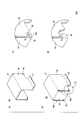
- FIG. 1B is a partially exploded perspective view of the configuration shown in FIG. 1A.
- 2B is a rear perspective view of the board mounting connector shown in FIG. 2A.
- FIG. 2B is an exploded perspective view of the board mounting connector shown in FIGS. 2A and 2B.
- FIG. The figure explaining a shield shell.
- (A) is a front perspective view of the shield shell shown in FIG.
- FIG. 3 is a rear perspective view of the shield shell shown in (a)
- (c) is an enlarged view of a part a of (b)
- (d) is ( The figure where a part of c) was fractured.
- (A) is the elements on larger scale of the shield shell shown in FIG. 4
- (b) is sectional drawing which shows the state in which the part shown to (a) was attached to the housing.
- FIG. 1 is a perspective view of a shield shell
- FIG. 1 is a perspective view of a shield shell
- FIG. 1 is a perspective view of a shield shell
- FIG. 1 is a perspective view of a shield shell
- FIG. 1 is a perspective view of a shield shell
- FIG. 1 is a perspective view of a shield shell
- FIG. 1 is a perspective view of a shield shell
- FIG. 1 is a perspective view of a shield shell
- FIG. 1 is a perspective view of a shield shell
- FIG. 1 is a perspective view of a shield shell
- FIG. 1 is a perspective view of a shield shell
- FIG. 1 is a perspective view of a shield shell
- FIG. 1 is a perspective view of a shield shell
- FIG. 1 is a perspective view of a shield shell
- FIG. 1 is a perspective view of a shield shell
- FIG. 1 is a perspective view of a shield shell
- FIG. 1 is a perspective view of a shield shell
- FIG. 3 shows parts of the disassembled board mounting connector 100.
- the board mounting connector 100 includes a housing 20, two contacts 30, and a shield shell 40.
- the housing 20 is formed of an insulator.
- the resin-made housing 20 has a rectangular parallelepiped main body portion 21 and two receiving portions 22 protruding rearward from the back surface 21b of the main body portion 21.
- An opening 23 is formed in the front surface 21 a of the main body 21.
- the opening 23 is a portion that fits into a mating connector inserted into the board mounting connector 100.
- Two holes 24 into which the contacts 30 are press-fitted are formed in the back surface 21 b of the main body 21. The two holes 24 communicate with the opening 23.
- the two receiving portions 22 are located at two corners on the bottom surface 21c side.
- An L-shaped groove 25 is formed on the upper surface of each receiving portion 22 (however, the upper surface is a surface close to the upper surface 21 f of the main body portion 21). With respect to one receiving portion 22, both ends of the groove 25 reach two adjacent sides of the upper surface of the one receiving portion 22. Similarly, with respect to the other receiving portion 22, both ends of the groove 25 reach two adjacent sides of the upper surface of the other receiving portion 22.
- a portion corresponding to one side of the L shape is parallel to the back surface 21 b, and a portion corresponding to the other side of the L shape is parallel to the side surface 21 d of the main body portion 21.
- a portion corresponding to one side of the L shape is parallel to the back surface 21 b, and a portion corresponding to the other side of the L shape is parallel to the side surface 21 e of the main body portion 21.
- Reference numeral 25 a indicates an inner wall surface of the groove 25.
- Each of the two contacts 30 is a metal pin.
- Each contact 30 includes a contact portion 31 accommodated in the main body portion 21 of the housing 20 and a leg portion 32 connected to the contact portion 31.
- the tips of the leg portions 32 are terminals 32a connected to a land pattern of a printed wiring board (not shown) by solder.
- a claw 33 for press-fitting is formed on the proximal end side of the contact portion 31.
- a positioning protrusion 34 that contacts the back surface 21 b of the main body 21 is formed at the base end of the leg 32 that is continuous with the contact portion 31.
- the shield shell 40 is formed by bending a single metal plate.
- FIG. 4 shows details of the shield shell 40.
- the illustrated shield shell 40 includes a rectangular plate portion 41 and three plate portions 42, 43, 44.
- the three plate portions 42, 43, 44 are plate portions that are bent in the same direction from the three sides of the rectangular plate portion 41.
- Adjacent plate portion 42 and plate portion 43 form a ridge 49a via a gap.
- Adjacent plate portion 44 and plate portion 43 form a ridge 49b through a gap.
- the plate portion 42 is not in contact with the plate portion 43.
- the plate portion 44 is not in contact with the plate portion 43 when the shield shell 40 is not attached to the housing 20.
- the plate portion 42 or the plate portion 44 corresponds to a first plate portion
- the plate portion 43 corresponds to a second plate portion.
- the shield shell 40 as a whole has a rectangular parallelepiped box shape having openings on two adjacent surfaces. In a state where the shield shell 40 is attached to the housing 20, the shield shell 40 covers the rear side of the housing 20, specifically, the contact 30.
- the rectangular plate portion 41 faces the upper surface 21f of the main body portion 21 of the housing 20, the plate portion 43 faces the back surface 21b of the main body portion 21, and the plate portions 42 and 44 face the side surfaces 21d and 21e of the main body portion 21, respectively. .
- two extension pieces 45 are formed on the lower end side of the plate portion 43 (the side away from the rectangular plate portion 41).
- the two extension pieces 45 are located at both ends in the width direction of the plate portion 43 (direction in which the plate portions 42 and 44 face each other).
- the one extension piece 45 is bent at a right angle to the normal direction of the plate portion 43 and faces the inner plate surface of the plate portion 42.
- the other extension piece 45 is bent at a right angle to the normal direction of the plate portion 43 and faces the inner plate surface of the plate portion 44.
- One protruding portion 46 is formed on the outer plate surface of the plate portion 42, and similarly, one protruding portion 46 is formed on the outer plate surface of the plate portion 44.
- a plate-like ground terminal 47 is formed at the lower end of the plate portion 42, and similarly, a plate-like ground terminal 47 is formed at the lower end of the plate portion 44. A configuration in which the ground terminal 47 is located in the vicinity of the extension piece 45 is preferable. Each ground terminal 47 extends toward the outside of the shield shell 40. Each ground terminal 47 is connected to the ground pattern of the printed wiring board by solder.
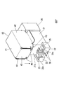
- FIG. 5 shows a state in which the shield shell 40 is attached to the housing 20 to which the contacts 30 are attached.
- the shield shell 40 is attached to the housing 20 from above the housing 20.
- the lower part of the corner formed by the plate part 42 and the plate part 43 is inserted into the groove 25 of the one receiving part 22, and the lower part of the corner formed by the plate part 43 and the plate part 44 is the other part. Is inserted into the groove 25 of the receiving portion 22.
- the leg portion 32 of the contact 30 protruding from the housing 20 is located between the two receiving portions 22.
- FIG. 6A is an enlarged view of a portion of the shield shell 40 where one extension piece 45 and one protrusion 46 are formed.
- FIG. 6B shows a state where the shield shell 40 is attached to the housing 20 and the part shown in FIG. 6A is inserted into the groove 25 of one receiving portion 22.
- one protrusion 46 has a pressing wall surface 25 b ( It is pressed by the outer wall surface of the groove 25 facing a part of the plate portion 42. Accordingly, the plate portion 42 is curved (displaced inward) as shown in FIG. 6B and is in contact with the extension piece 45. The same can be said for the relationship between the other extension piece 45 and the other protrusion 46.
- one portion of the inner plate surface of the plate portion 42 or the plate portion 44 corresponds to the first contact portion
- one portion of the outer plate surface of the extension piece 45 corresponding to the first plate portion is the first portion.
- the pressing wall surface 25b which is a part of the housing 20, corresponds to the pressing portion. Furthermore, in 1st Embodiment, the protrusion part 46 which is one site
- the lower surfaces of the two projecting portions 46 are inclined surfaces 46a.
- the shield shell 40 is easily inserted into the groove 25 by the inclined surface 46a.
- the shield shell 40 when the shield shell 40 is attached to the housing 20, one short circuit path via the extension piece 45 is connected to the plate portion 43 and the plate portion.
- the other short-circuit path through the extension piece 45 is formed between the plate portion 43 and the plate portion 44. Since the short-circuit path functioning as a new conductive path is formed in this way, the conductive path through which noise flows is shortened. For example, the noise received by the plate portion 43 from the leg portion 32 of the contact 30 flows through the rectangular plate portion 41 and the plate portions 42 and 44 of the housing 20 to the ground terminal 47 when there is no short-circuit path via the extension piece 45.
- FIG. 7 is a partially exploded perspective view of the board mounting connector having the shield shell 50 having such a configuration.
- One extension piece 45 is formed on the lower end side of the plate portion 42 (the side away from the rectangular plate portion 41).
- One extension piece 45 is a length direction of the plate portion 42 (however, the length direction is parallel to the direction in which the front surface 21a and the back surface 21b face each other in a state where the shield shell 50 is attached to the housing 20). It is located at the end on the back surface 21b side.
- the other extension piece 45 is formed on the lower end side of the plate portion 44.
- the other extension piece 45 is located at the end of the plate portion 44 on the back surface 21b side in the length direction.
- the two extension pieces 45 formed on the plate portions 42 and 44 are each bent at a right angle and face the inner plate surface of the plate portion 43.
- Two protruding portions 46 are formed on the plate portion 43. When the plate portion 43 is viewed from the front, the two protruding portions 46 overlap the two extension pieces 45.
- the outer wall surface of one side of the L shape (however, this side is parallel to the back surface 21 b) is the pressing wall surface 25 c that presses the protruding portion 46.
- the shield shell 50 is attached to the housing 20 from above the housing 20.
- the plate portion 42 or the plate portion 44 corresponds to the second plate portion
- the plate portion 43 corresponds to the first plate portion
- one portion of the inner plate surface of the plate portion 43 corresponds to the first contact portion
- one portion of the outer plate surface of each extension piece 45 corresponds to the second contact portion.
- the pressing wall surface 25c which is one part, corresponds to the pressing portion.
- the protrusion part 46 which is one site
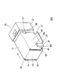
- FIG. 8 is a partially exploded perspective view of a board mounting connector having a configuration in which a shield shell is attached to the housing from the rear of the housing.
- the shield shell 60 similarly to the shield shell 40, two extension pieces 45 are formed on the plate portion 43, one protrusion 46 is formed on the plate 42, and one protrusion 46 is formed. Is formed on the plate portion 44.
- a groove 26 extending in the length direction of the housing 20 is formed in one receiving portion 22 of the housing 20, and similarly, the other receiving portion 22 has a housing 26. A groove 26 extending in the length direction of 20 is formed.
- the shield shell 60 is combined with the housing 20 from above the housing 20. In this state, the two receiving portions 22 are respectively positioned between the protruding portion 46 and the ground terminal 47, and a part of the plate portion 42 is fitted in the groove 26 of the one receiving portion 22.
- a part of 44 is fitted in the groove 26 of the other receiving part 22. Furthermore, by sliding the shield shell 60 toward the front surface 21 a of the housing 20, the pressing wall surface 26 a that is the outer wall surface of the groove 26 presses the protruding portion 46.
- the side surface of the protrusion part 46 which faces the front surface 21a in the state in which the shield shell 60 is attached to the housing 20 is the inclined surface 46b.
- Two notches 48 that fit into the two protrusions 27 formed on the main body 21 of the housing 20 are formed on the front edges of the plate portions 42 and 44 in the length direction.
- the plate portion 42 or the plate portion 44 corresponds to the first plate portion
- the plate portion 43 corresponds to the second plate portion.
- one portion of the inner plate surface of the first plate portion corresponds to the first contact portion
- one portion of the outer plate surface of the extension piece 45 corresponding to the first plate portion is the second portion.
- the pressing wall surface 26a corresponding to the contact portion and one part of the housing 20 corresponds to the pressing portion.
- the protrusion part 46 which is one site
- the shield shell 70 of the board mounting connector includes a rectangular plate portion 41 and three plate portions 42, 43, and 44.
- the three plate portions 42, 43, 44 are plate portions that are bent in the same direction from the three sides of the rectangular plate portion 41.
- Adjacent plate portion 42 and plate portion 43 form a ridge 49a via a gap.
- Adjacent plate portion 44 and plate portion 43 form a ridge 49b through a gap.
- the rectangular plate portion 41 faces the back surface 21 b of the main body portion 21 in a state where the shield shell 70 is attached to the housing 20.
- two extension pieces 45 are formed on the plate portion 43, one protrusion 46 is formed on the plate portion 42, and one protrusion 46 is formed on the plate portion 44.
- One groove 28 extending in the length direction of the housing 20 is formed in one receiving portion 22 of the housing 20.
- the other groove 28 extending in the length direction of the housing 20 is formed in the other receiving portion 22.
- Two grooves 29 from the upper surface 21f to a predetermined depth are formed in the main body portion 21 of the housing 20 along the height direction (however, the height direction is a direction in which the upper surface 21f and the bottom surface 21c face each other). ing.
- the positions of the two grooves 29 correspond to the positions of the front ends (tips) of the plate portions 42 and 44.
- the shield shell 70 is attached to the housing 20 from above the housing 20.
- the front end of the plate portion 42 is inserted into one groove 29, and the front end of the plate portion 44 is inserted into the other groove 29.
- the lower portion of the rear end of the plate portion 42 is inserted into the groove 28 of one receiving portion 22, and the lower portion of the rear end of the plate portion 44 is inserted into the groove 28 of the other receiving portion 22.
- the pressing wall surface 29 a that is the outer wall surface of the groove 29 presses the protruding portion 46.
- the lower surface of the protrusion 46 is an inclined surface 46a.
- the ground terminal 47 is formed at the lower end of the plate portion 42, and similarly, the ground terminal 47 is formed at the lower end of the plate portion 44.
- one short-circuit path is formed between the plate portion 43 facing the upper surface 21 f of the main body portion 21 of the housing 20 and the plate portion 42 facing the side surface 21 d, and further, the main body portion 21 of the housing 20.
- the other short-circuit path is formed between the plate portion 43 facing the upper surface 21f and the plate portion 44 facing the side surface 21e.
- the plate portion 42 or the plate portion 44 corresponds to the first plate portion
- the plate portion 43 corresponds to the second plate portion.
- one portion of the inner plate surface of the first plate portion corresponds to the first contact portion
- one portion of the outer plate surface of the extension piece 45 corresponding to the first plate portion is the second portion.
- the pressing wall surface 29a which corresponds to the contact portion and is a part of the housing 20, corresponds to the pressing portion.
- the protrusion part 46 which is one site
- an extension piece is formed on one of the adjacent plate portions across the ridge, and a pressed portion that is pressed by the pressing portion is formed on the other side. Therefore, by the extension piece that is one contact portion and the inner plate surface that is the other contact portion (however, this inner plate surface is the inner plate surface of the plate portion on which the protruding portion is formed).
- a short circuit path is constructed.
- the configuration of the short circuit path is not limited to this configuration. Hereinafter, another configuration will be described with reference to FIGS. 10 and 11.
- one extension piece 45 formed on the plate portion 43 extends from the edge of the one extension piece 45 in a direction orthogonal to the extension direction of the one extension piece 45.
- the other extension piece 45 includes the other extension part 81 extending from the edge of the other extension piece 45 in a direction perpendicular to the extension direction of the other extension piece 45.
- Each extension portion 81 has a U-shaped bent shape. The bottom portion of one extension portion 81 wraps around the lower side of the nearest plate portion 42, and the bottom portion of the other extension portion 81 wraps around the lower side of the nearest plate portion 44. One end portion of one extension portion 81 is located outside the plate portion 42, and one end portion of the other extension portion 81 is located outside the plate portion 44.
- one end of the extension part 81 is an insertion part 82, and a bent part 82a that is slightly bent outward is formed at the tip of the insertion part 82.
- One insertion portion 82 is located in a gap between the plate portion 42 and the pressing portion formed in the housing 20 in a state where the shield shell 80 is attached to the housing 20.
- the other insertion portion 82 is located in a gap between the plate portion 44 and the pressing portion formed in the housing 20 in a state where the shield shell 80 is attached to the housing 20.
- the plate portion 42 or the plate portion 44 corresponds to the first plate portion
- the plate portion 43 corresponds to the second plate portion.
- one portion of the outer plate surface of the first plate portion corresponds to the first contact portion
- one portion (inner side surface) of the insertion portion 82 corresponding to the first plate portion is the second.
- the pressing wall surface corresponding to the contact portion and one part of the housing 20 corresponds to the pressing portion.
- one part (specifically, the bent part 82a) of the first extension piece different from the second contact part corresponds to the pressed part. That is, the second contact part and the pressed part are located in the insertion part.
- one extension piece 91 is formed on the plate portion 42, and similarly, one extension piece 91 is formed on the plate portion 44.
- Each extension 91 has a U-shaped bent shape.
- Each of the two extension pieces 45 formed on the plate portion 43 is bent at a right angle.
- One extension piece 45 faces the outer plate surface of the plate portion 42, and the other extension piece 45 faces the outer plate surface of the plate portion 44.
- the bottom part of one extension piece 91 wraps around the lower side of one extension piece 45, and the bottom part of the other extension piece 91 wraps around the lower side of the other extension piece 45.
- One end of one extension 91 is located outside one extension piece 45, and one end of the other extension 91 is located outside the other extension piece 45.
- one end of the extension piece 91 is an insertion portion 92, and a bent portion 92 a that is slightly bent outward is formed at the tip of the insertion portion 92.
- the one insertion portion 92 is located in a gap between the one extension piece 45 and the pressing portion formed in the housing 20 in a state where the shield shell 90 is attached to the housing 20.
- the other insertion portion 92 is located in a gap between the other extension piece 45 and the pressing portion formed in the housing 20 in a state where the shield shell 90 is attached to the housing 20.
- the plate portion 42 or the plate portion 44 corresponds to the first plate portion
- the plate portion 43 corresponds to the second plate portion.
- one portion (inner side surface) of the insertion portion 92 corresponding to the first plate portion corresponds to the first contact portion
- the part corresponds to the second contact part
- the pressing wall surface which is one part of the housing 20 corresponds to the pressing part.
- one portion (specifically, the bent portion 92a) of the second extension piece different from the first contact portion corresponds to the pressed portion. That is, the first contact portion and the pressed portion are located on the second extension piece.
- the pressing portion for short-circuiting the plate surfaces of adjacent shield shells by pressing the pressed portion is a state where the shield shell is attached to the housing. Is located outside the shield shell and presses the pressed portion inward.
- the pressing portion presses the pressed portion outward.
- transformation of a shield shell is preferable.
- the pressing portion is not limited to the wall surface of the groove, and the groove structure of the receiving portion is not an essential component.
- the shield shell has the rectangular plate portion 41 and three plate portions bent at right angles in the same direction from the three sides of the rectangular plate portion 41, and is adjacent to the three plate portions.
- the plate portion forms a ridge.
- the present invention is not limited to such a configuration. For example, a shield shell having no square plate portion or a shield shell having a plate portion connected to a bend having a large radius of curvature is allowed.
- the first contact portion and the second contact portion are located at a portion away from the rectangular plate portion (for example, the edge portion of the corresponding plate portion or the vicinity of the edge portion). It is preferable.
- one of the first plate portion and the second plate portion faces the contact, and the first plate portion and the second plate portion A configuration in which a ground terminal is formed on the other of the plate portions is preferable.
- the noise received by the shield shell is not limited to the noise received from the leg portion of the contact.
- the shield shell receives noise from the outside of the shield shell, for example.
- a description of the advantages of the present invention when the noise source is not limited will be added.
- L1> L2 or L2> L1 in the actually manufactured connector To establish. A case where L1> L2 will be described.
- a conductive path (a conductive path shorter than L1) that bridges the first plate portion and the second plate portion through which non-zero noise of the first plate portion can flow. Therefore, the board mounting connector of the present invention has a good shielding performance. The same applies to L2> L1.
- ground terminal 47 not only the ground terminal 47 but also the shield shell plate facing the upper surface 21f of the housing 20 may be grounded.
- a frame ground in which a grounding terminal formed on the plate portion of the shield shell facing the upper surface 21f of the housing 20 is connected to the housing can be exemplified.
- the ground terminal 47 may be connected to the housing instead of the ground pattern on the substrate.
- a short-circuit path in the shield shell attached to the housing, can be formed between adjacent plate portions with a gap therebetween.
- This short circuit path functions as a conductive path through which noise flows in the shield shell.
- a conductive path through which noise flows is formed only within a continuous plate surface, but according to the present invention, a new conductive path is provided between non-continuous plate surfaces, so that better shielding performance can be achieved.
- the board mounting connector is realized.
Abstract
In this invention, a shield shell (40) includes a first plate portion (42) and a second plate portion (43), which are adjacent to one another. One site in the first plate portion (42) is a first contact portion. A first elongated strip (45) is formed in the second plate portion (43). One site in the first elongated strip (45) is a second contact portion. One site in a housing (20) is a pressing portion (25b) facing the first plate portion (42) in a covering state wherein the shield shell (40) is fitted onto the housing (20). One site on the first plate portion (42) that is different from the first contact portion, or, one site on the first elongated strip (45) that is different from the second contact portion is a pressed portion (46), which is pressed by the pressing portion (25b) in the covering state. Fitting the shield shell (40) onto the housing (20) causes the pressing portion (25b) to press the pressed portion (46), and the first contact portion to contact the second contact portion.
Description
本発明は、シールドシェルを備えた基板実装用コネクタに関する。
The present invention relates to a board mounting connector provided with a shield shell.
図1A,1Bは、この種の基板実装用コネクタの従来例として、特許文献1に記載されているレセプタクルコネクタの構成を示している。レセプタクルコネクタ10は、絶縁ハウジング11と、シールドシェル金具12と、複数のコンタクト13と、シールドカバー14とを含む。シールドシェル金具12と複数のコンタクト13は、絶縁ハウジング11に一体に取り付けられている。シールドカバー14は、絶縁ハウジング11の後方の平面と両側面に沿って取り付けられている。
1A and 1B show a configuration of a receptacle connector described in Patent Document 1 as a conventional example of this type of board mounting connector. Receptacle connector 10 includes an insulating housing 11, a shield shell fitting 12, a plurality of contacts 13, and a shield cover 14. The shield shell fitting 12 and the plurality of contacts 13 are integrally attached to the insulating housing 11. The shield cover 14 is attached along the rear plane and both side surfaces of the insulating housing 11.
シールドシェル金具12は嵌合筒部12aを有する。嵌合筒部12aは、レセプタクルコネクタ10に挿入される相手方プラグに嵌合する部分である。シールドシェル金具12が取り付けられている絶縁ハウジング11は、嵌合筒部12aの外周面と後方の開口(嵌合筒部12aの前方の開口は、相手方プラグが挿入される開口である)を覆っている。絶縁ハウジング11は、嵌合筒部12a内で前方に突出する支持板部(図1A,1Bでは見えない)を有している。絶縁ハウジング11に取り付けられている複数のコンタクト13の先端側の接触部(図1A,1Bでは見えない)は、絶縁ハウジング11の支持板部に沿って露出している。複数のコンタクト13の脚部13aは、絶縁ハウジング11から後方に突出している。複数のコンタクト13の脚部13aは、シールドカバー14によって囲まれている。
The shield shell metal fitting 12 has a fitting cylinder portion 12a. The fitting cylinder portion 12 a is a portion that fits into a mating plug inserted into the receptacle connector 10. The insulating housing 11 to which the shield shell metal fitting 12 is attached covers the outer peripheral surface of the fitting cylinder portion 12a and the rear opening (the opening in front of the fitting cylinder portion 12a is an opening into which the mating plug is inserted). ing. The insulating housing 11 has a support plate portion (not visible in FIGS. 1A and 1B) that protrudes forward in the fitting cylinder portion 12a. Contact portions (not visible in FIGS. 1A and 1B) on the tip side of the plurality of contacts 13 attached to the insulating housing 11 are exposed along the support plate portion of the insulating housing 11. Leg portions 13 a of the plurality of contacts 13 protrude rearward from the insulating housing 11. The leg portions 13 a of the plurality of contacts 13 are surrounded by the shield cover 14.
シールドカバー14に形成されている2個の接触舌片14aは、絶縁ハウジング11に形成された2個の挿通孔11aに圧入されている。各接触舌片14aは、対応する挿通孔11aを介して露出している嵌合筒部12aの露出部に接触している。図1A,1B中、符号12bはシールドシェル金具12に形成されている2個の接地脚部を示し、符号12cは絶縁ハウジング11に形成されている2個の挿通孔11bを介して外方に露出するシールドシェル金具12の外部露出部を示す。
The two contact tongues 14 a formed in the shield cover 14 are press-fitted into the two insertion holes 11 a formed in the insulating housing 11. Each contact tongue piece 14a is in contact with the exposed portion of the fitting tube portion 12a exposed through the corresponding insertion hole 11a. In FIGS. 1A and 1B, reference numeral 12 b indicates two grounding legs formed on the shield shell metal fitting 12, and reference numeral 12 c indicates outward through two insertion holes 11 b formed in the insulating housing 11. The exposed external part of the shield shell metal fitting 12 exposed is shown.
レセプタクルコネクタ10では、シールドシェル金具12とシールドカバー14の両方の外部遮蔽によってコンタクト13が電磁シールドされている。したがって、コンタクト13に流れる高周波信号の外部への輻射、および、外部からのノイズの高周波信号への重畳が防止される。
In the receptacle connector 10, the contact 13 is electromagnetically shielded by the external shielding of both the shield shell metal fitting 12 and the shield cover 14. Therefore, the radiation of the high frequency signal flowing through the contact 13 to the outside and the superposition of noise from the outside to the high frequency signal are prevented.
コンタクトを保持するハウジングを覆うシールドシェルを備える基板実装用コネクタにおいて、シールドシェルにおいてノイズ(高周波ノイズ)が流れる導電経路が長い場合、十分なシールド効果を得られない。したがって、ノイズが流れる導電経路をできるだけ短くすることが重要である。
In a board mounting connector including a shield shell that covers a housing that holds a contact, if the conductive path through which noise (high frequency noise) flows is long in the shield shell, a sufficient shielding effect cannot be obtained. Therefore, it is important to make the conductive path through which noise flows as short as possible.
シールドシェルは、一般的に、一枚の金属板をプレス加工することによって形成される、つまり、一枚の金属板を折り曲げることによってハウジングの複数の面を覆う形状が形成される。このため、折り曲げられることによって隣り合う二つの面は直接短絡しない。実際、図1A,1Bに示す従来のレセプタクルコネクタ10において絶縁ハウジング11を覆うシールドカバー14も、隣り合う二つの面が直接短絡しない構成を持つ。
The shield shell is generally formed by pressing a single metal plate, that is, a shape covering a plurality of surfaces of the housing is formed by bending the single metal plate. For this reason, two adjacent surfaces are not short-circuited directly by being bent. In fact, the shield cover 14 covering the insulating housing 11 in the conventional receptacle connector 10 shown in FIGS. 1A and 1B also has a configuration in which two adjacent surfaces are not directly short-circuited.
図1A,1Bに示すシールドカバー14の場合、絶縁ハウジング11の後方を覆う背板部14bがコンタクト13の脚部13aから受けるノイズは、絶縁ハウジング11の平面を覆う上方の取付板部14c、接触舌片14a、嵌合筒部12aの露出部、接地脚部12bにこの順序で流れる。このため、ノイズが流れる導電経路は短いとは言えない。この観点からは、レセプタクルコネクタ10のシールド性能は良好とは言えない。
In the case of the shield cover 14 shown in FIGS. 1A and 1B, the noise received by the back plate portion 14 b covering the back of the insulating housing 11 from the leg portion 13 a of the contact 13 is caused by contact with the upper mounting plate portion 14 c that covers the plane of the insulating housing 11. It flows in this order to the tongue piece 14a, the exposed part of the fitting cylinder part 12a, and the grounding leg part 12b. For this reason, it cannot be said that the conductive path through which noise flows is short. From this point of view, the shielding performance of the receptacle connector 10 is not good.
シールド性能を向上させるために、例えば、シールドカバー14の背板部14bに接地端子を形成し、レセプタクルコネクタ10が実装されるプリント配線基板に接地パターンを形成する構成が考えられる。接地端子を接地パターンに接続することによって、ノイズが流れる導電経路を短くできる。しかし、この場合、設計自由度が阻害される。例えば、多数のコンタクト13に接続するためのランドパターンが密集している場合、接地パターンの形成は困難である。したがって、コンタクト13の数が制限される。接地パターンをランドパターンから離れた場所に形成するならば、接地パターンから接地端子までの距離が長くなる。
In order to improve the shielding performance, for example, a configuration in which a ground terminal is formed on the back plate portion 14b of the shield cover 14 and a ground pattern is formed on the printed wiring board on which the receptacle connector 10 is mounted is conceivable. By connecting the ground terminal to the ground pattern, the conductive path through which noise flows can be shortened. However, in this case, the degree of freedom in design is hindered. For example, when land patterns for connecting to a large number of contacts 13 are dense, it is difficult to form a ground pattern. Therefore, the number of contacts 13 is limited. If the ground pattern is formed at a location away from the land pattern, the distance from the ground pattern to the ground terminal is increased.
シールド性能を向上させるために、シールドカバー14の取付板部14cに接地端子を形成する構成が考えられる。しかし、この場合、ノイズが流れる導電経路の長さは、概ね、背板部14bの高さに依存する。相手方プラグの寸法、製造規格などの理由によって設計条件を自由に変更できない場合、必ずしも背板部14bの高さを小さくできない。
In order to improve shield performance, a configuration in which a ground terminal is formed on the mounting plate portion 14c of the shield cover 14 is conceivable. However, in this case, the length of the conductive path through which noise flows generally depends on the height of the back plate portion 14b. If the design conditions cannot be changed freely for reasons such as the size of the mating plug and the manufacturing standard, the height of the back plate portion 14b cannot necessarily be reduced.
本発明者らは、従来例では連続した板面内だけに導電経路が形成される事実に着眼した。つまり、本発明者らは、この事実が設計自由度とノイズの流れる導電経路の長さの低減に制約を与えていたことに気付いた。
The present inventors focused on the fact that the conductive path is formed only in the continuous plate surface in the conventional example. That is, the present inventors have noticed that this fact has constrained the reduction in design freedom and the length of the conductive path through which noise flows.
本発明の目的は、ノイズが流れることのできる、できるだけ短い導電経路をシールドシェルにおいて提供し、かつ、シールドシェルにおける接地端子の位置を制限することなく、良好なシールド性能を有する基板実装用コネクタを提供することである。
SUMMARY OF THE INVENTION An object of the present invention is to provide a board mounting connector that provides a shortest possible conductive path in a shield shell through which noise can flow, and has good shielding performance without limiting the position of the ground terminal in the shield shell. Is to provide.
本発明の基板実装用コネクタは、絶縁体で形成されたハウジングと、ハウジングに取り付けられているコンタクトと、金属板で形成されているシールドシェルとを含む。
シールドシェルは、ハウジングに取り付けられており、コンタクトを覆っている。シールドシェルは、隣り合う第1の板部と第2の板部を含む。シールドシェルがハウジングに取り付けられていない状態において、第1の板部は第2の板部に接触していない。
第1の板部の一部位は、第1の接触部である。第1の延長片が、第2の板部に形成されている。第1の延長片の一部位は、第2の接触部である。
ハウジングの一部位は、シールドシェルがハウジングに取り付けられている状態において第1の板部に対向する押圧部である。第1の接触部と異なる第1の板部の一部位、または、第2の接触部と異なる第1の延長片の一部位は、シールドシェルがハウジングに取り付けられている状態において押圧部によって押圧される被押圧部である。
シールドシェルがハウジングに取り付けられることによって押圧部が被押圧部を押圧し、第1の接触部が第2の接触部に接触する。 The board mounting connector of the present invention includes a housing formed of an insulator, contacts attached to the housing, and a shield shell formed of a metal plate.
The shield shell is attached to the housing and covers the contact. The shield shell includes a first plate portion and a second plate portion which are adjacent to each other. In a state where the shield shell is not attached to the housing, the first plate portion is not in contact with the second plate portion.
One part of the first plate portion is a first contact portion. The 1st extension piece is formed in the 2nd board part. One part of the first extension piece is a second contact portion.
One portion of the housing is a pressing portion that faces the first plate portion when the shield shell is attached to the housing. One portion of the first plate portion different from the first contact portion or one portion of the first extension piece different from the second contact portion is pressed by the pressing portion in a state where the shield shell is attached to the housing. It is a pressed part.
When the shield shell is attached to the housing, the pressing portion presses the pressed portion, and the first contact portion comes into contact with the second contact portion.
本発明によれば、間隙を持つ稜を形成する隣り合うシールドシェルの二つの板部の間に短絡経路が形成される。この短絡経路は、シールドシェルにおいてノイズが流れる導電経路として機能する。つまり、従来例では連続した板面内だけにノイズの流れる導電経路が形成されたが、本発明によると、連続しない板面間に新たな導電経路が提供される。このように、本発明の基板実装用コネクタは、ノイズが流れることのできる、できるだけ短い導電経路をシールドシェルに含み、良好なシールド性能を有する。また、上述の本発明の構成のとおり、シールドシェルにおいて接地端子の位置に対する制限は無い。
According to the present invention, a short-circuit path is formed between two plate portions of adjacent shield shells that form a ridge having a gap. This short circuit path functions as a conductive path through which noise flows in the shield shell. That is, in the conventional example, a conductive path through which noise flows is formed only within a continuous plate surface, but according to the present invention, a new conductive path is provided between non-continuous plate surfaces. As described above, the board mounting connector of the present invention includes a conductive path as short as possible in the shield shell through which noise can flow, and has a good shielding performance. Moreover, there is no restriction | limiting with respect to the position of a ground terminal in a shield shell as the structure of the above-mentioned this invention.
本発明の実施形態を、図面を参照して説明する。
Embodiments of the present invention will be described with reference to the drawings.
<第1実施形態>
図2A,2Bは、本発明の第1実施形態である基板実装用コネクタ100を示している。図3は、分解された基板実装用コネクタ100の各部を示している。基板実装用コネクタ100は、第1実施形態では、ハウジング20と、2個のコンタクト30と、シールドシェル40とを含む。ハウジング20は絶縁体で形成されている。 <First Embodiment>
2A and 2B show aboard mounting connector 100 according to the first embodiment of the present invention. FIG. 3 shows parts of the disassembled board mounting connector 100. In the first embodiment, the board mounting connector 100 includes a housing 20, two contacts 30, and a shield shell 40. The housing 20 is formed of an insulator.
図2A,2Bは、本発明の第1実施形態である基板実装用コネクタ100を示している。図3は、分解された基板実装用コネクタ100の各部を示している。基板実装用コネクタ100は、第1実施形態では、ハウジング20と、2個のコンタクト30と、シールドシェル40とを含む。ハウジング20は絶縁体で形成されている。 <First Embodiment>
2A and 2B show a
樹脂製のハウジング20は、直方体状の本体部21と、本体部21の背面21bから後方に突出している2個の受部22とを有する。開口23が本体部21の前面21aに形成されている。開口23は、基板実装用コネクタ100に挿入される相手方コネクタに嵌合する部分である。コンタクト30が圧入される2個の穴24が、本体部21の背面21bに形成されている。2個の穴24は開口23に連通している。
The resin-made housing 20 has a rectangular parallelepiped main body portion 21 and two receiving portions 22 protruding rearward from the back surface 21b of the main body portion 21. An opening 23 is formed in the front surface 21 a of the main body 21. The opening 23 is a portion that fits into a mating connector inserted into the board mounting connector 100. Two holes 24 into which the contacts 30 are press-fitted are formed in the back surface 21 b of the main body 21. The two holes 24 communicate with the opening 23.
背面21bにおいて、2個の受部22は、底面21c側の2個の角部に位置する。L字状の溝25が、各受部22の上面(ただし、上面は、本体部21の上面21fに近い面である)に形成されている。一方の受部22について、溝25の両端は一方の受部22の上面の隣接する2辺に達している。同様に、他方の受部22について、溝25の両端は他方の受部22の上面の隣接する2辺に達している。一方の溝25について、L字の一方の辺に相当する部分は背面21bと平行であり、L字の他方の辺に相当する部分は本体部21の側面21dと平行である。同様に、他方の溝25について、L字の一方の辺に相当する部分は背面21bと平行であり、L字の他方の辺に相当する部分は本体部21の側面21eと平行である。符号25aは溝25の内側の壁面を示す。
In the back surface 21b, the two receiving portions 22 are located at two corners on the bottom surface 21c side. An L-shaped groove 25 is formed on the upper surface of each receiving portion 22 (however, the upper surface is a surface close to the upper surface 21 f of the main body portion 21). With respect to one receiving portion 22, both ends of the groove 25 reach two adjacent sides of the upper surface of the one receiving portion 22. Similarly, with respect to the other receiving portion 22, both ends of the groove 25 reach two adjacent sides of the upper surface of the other receiving portion 22. In one groove 25, a portion corresponding to one side of the L shape is parallel to the back surface 21 b, and a portion corresponding to the other side of the L shape is parallel to the side surface 21 d of the main body portion 21. Similarly, with respect to the other groove 25, a portion corresponding to one side of the L shape is parallel to the back surface 21 b, and a portion corresponding to the other side of the L shape is parallel to the side surface 21 e of the main body portion 21. Reference numeral 25 a indicates an inner wall surface of the groove 25.
2個のコンタクト30はそれぞれ、金属ピンである。各コンタクト30は、ハウジング20の本体部21に収容される接触部31と、接触部31に連なる脚部32とを含む。脚部32の先端は、プリント配線基板(図示せず)のランドパターンに半田で接続される端子32aである。圧入のための爪33が、接触部31の基端側に形成されている。本体部21の背面21bに接触する位置決め突部34が、接触部31に連なる脚部32の基端に形成されている。
Each of the two contacts 30 is a metal pin. Each contact 30 includes a contact portion 31 accommodated in the main body portion 21 of the housing 20 and a leg portion 32 connected to the contact portion 31. The tips of the leg portions 32 are terminals 32a connected to a land pattern of a printed wiring board (not shown) by solder. A claw 33 for press-fitting is formed on the proximal end side of the contact portion 31. A positioning protrusion 34 that contacts the back surface 21 b of the main body 21 is formed at the base end of the leg 32 that is continuous with the contact portion 31.
シールドシェル40は、単一の金属板を折り曲げて形成される。図4は、シールドシェル40の詳細を示している。例示のシールドシェル40は、方形板部41と、3つの板部42,43,44とを含む。3つの板部42,43,44は、方形板部41の3辺から同じ方向に折り曲げられた板部である。隣り合う板部42と板部43は間隙を介して稜49aを形成している。隣り合う板部44と板部43は間隙を介して稜49bを形成している。シールドシェル40がハウジング20に取り付けられていない状態において、板部42は板部43に接触していない。同様に、シールドシェル40がハウジング20に取り付けられていない状態において、板部44は板部43に接触していない。第1実施形態では、板部42または板部44が第1の板部に相当し、板部43が第2の板部に相当する。
The shield shell 40 is formed by bending a single metal plate. FIG. 4 shows details of the shield shell 40. The illustrated shield shell 40 includes a rectangular plate portion 41 and three plate portions 42, 43, 44. The three plate portions 42, 43, 44 are plate portions that are bent in the same direction from the three sides of the rectangular plate portion 41. Adjacent plate portion 42 and plate portion 43 form a ridge 49a via a gap. Adjacent plate portion 44 and plate portion 43 form a ridge 49b through a gap. In a state where the shield shell 40 is not attached to the housing 20, the plate portion 42 is not in contact with the plate portion 43. Similarly, the plate portion 44 is not in contact with the plate portion 43 when the shield shell 40 is not attached to the housing 20. In the first embodiment, the plate portion 42 or the plate portion 44 corresponds to a first plate portion, and the plate portion 43 corresponds to a second plate portion.
シールドシェル40は、全体として、隣り合う2面に開口を持つ直方体の箱状の形状を持つ。シールドシェル40がハウジング20に取り付けられている状態において、シールドシェル40は、ハウジング20の後ろ側、具体的にはコンタクト30を覆う。方形板部41はハウジング20の本体部21の上面21fに対向し、板部43は本体部21の背面21bに対向し、板部42,44は本体部21の側面21d,21eにそれぞれ対向する。
The shield shell 40 as a whole has a rectangular parallelepiped box shape having openings on two adjacent surfaces. In a state where the shield shell 40 is attached to the housing 20, the shield shell 40 covers the rear side of the housing 20, specifically, the contact 30. The rectangular plate portion 41 faces the upper surface 21f of the main body portion 21 of the housing 20, the plate portion 43 faces the back surface 21b of the main body portion 21, and the plate portions 42 and 44 face the side surfaces 21d and 21e of the main body portion 21, respectively. .
第1実施形態では、2個の延長片45が、板部43の下端側(方形板部41から離れる側)に形成されている。2個の延長片45は、板部43の幅方向(板部42,44が対向する方向)の両端に位置している。一方の延長片45は、図4(d)に例示するとおり、板部43の法線方向に直角に折り曲げられており、板部42の内側板面に対向している。同様に、他方の延長片45は、板部43の法線方向に直角に折り曲げられており、板部44の内側板面に対向している。1個の突出部46が板部42の外側板面に形成されており、同様に、1個の突出部46が板部44の外側板面に形成されている。板部42を正視したとき、板部42に形成されている突出部46は一方の延長片45とオーバーラップする。板部44を正視したとき、板部44に形成されている突出部46は他方の延長片45とオーバーラップする。板状の接地端子47が板部42の下端に形成されており、同様に、板状の接地端子47が板部44の下端に形成されている。接地端子47が延長片45の近傍に位置する構成が好ましい。各接地端子47は、シールドシェル40の外側に向かって延長している。各接地端子47は、プリント配線基板の接地パターンに半田で接続される。
In the first embodiment, two extension pieces 45 are formed on the lower end side of the plate portion 43 (the side away from the rectangular plate portion 41). The two extension pieces 45 are located at both ends in the width direction of the plate portion 43 (direction in which the plate portions 42 and 44 face each other). As illustrated in FIG. 4D, the one extension piece 45 is bent at a right angle to the normal direction of the plate portion 43 and faces the inner plate surface of the plate portion 42. Similarly, the other extension piece 45 is bent at a right angle to the normal direction of the plate portion 43 and faces the inner plate surface of the plate portion 44. One protruding portion 46 is formed on the outer plate surface of the plate portion 42, and similarly, one protruding portion 46 is formed on the outer plate surface of the plate portion 44. When the plate portion 42 is viewed from the front, the protruding portion 46 formed on the plate portion 42 overlaps the one extension piece 45. When the plate portion 44 is viewed from the front, the protruding portion 46 formed on the plate portion 44 overlaps the other extension piece 45. A plate-like ground terminal 47 is formed at the lower end of the plate portion 42, and similarly, a plate-like ground terminal 47 is formed at the lower end of the plate portion 44. A configuration in which the ground terminal 47 is located in the vicinity of the extension piece 45 is preferable. Each ground terminal 47 extends toward the outside of the shield shell 40. Each ground terminal 47 is connected to the ground pattern of the printed wiring board by solder.
図5は、コンタクト30が取り付けられたハウジング20に、シールドシェル40が取り付けられる様子を示している。シールドシェル40は、ハウジング20の上方からハウジング20に取り付けられる。この際、板部42と板部43が形成する角部の下側部位は一方の受部22の溝25に挿入され、板部43と板部44が形成する角部の下側部位は他方の受部22の溝25に挿入される。ハウジング20から突出しているコンタクト30の脚部32は、2個の受部22の間に位置している。
FIG. 5 shows a state in which the shield shell 40 is attached to the housing 20 to which the contacts 30 are attached. The shield shell 40 is attached to the housing 20 from above the housing 20. At this time, the lower part of the corner formed by the plate part 42 and the plate part 43 is inserted into the groove 25 of the one receiving part 22, and the lower part of the corner formed by the plate part 43 and the plate part 44 is the other part. Is inserted into the groove 25 of the receiving portion 22. The leg portion 32 of the contact 30 protruding from the housing 20 is located between the two receiving portions 22.
図6(a)は、シールドシェル40において一方の延長片45と一方の突出部46が形成されている部位の拡大図である。シールドシェル40がハウジング20に取り付けられていない状態では、図6(a)に示すように、稜49aを挟んで隣り合う板部42と板部43との間に間隙sが存在する。図6(b)は、シールドシェル40がハウジング20に取り付けられ、図6(a)に示す部位が一方の受部22の溝25に挿入された状態を示している。シールドシェル40の下側に位置する4個の角部のうちの2個の後ろ側角部が2個の溝25に挿入されることによって、一方の突出部46は溝25の押圧壁面25b(板部42の一部に対向する溝25の外側の壁面)によって押圧される。したがって、板部42は、図6(b)に示すように湾曲し(内向きに変位し)、延長片45と接触する。
他方の延長片45と他方の突出部46との関係についても、ここで説明したのと同じことが言える。
第1実施形態では、板部42または板部44の内側板面の一部位が第1の接触部に相当し、第1の板部に対応する延長片45の外側板面の一部位が第2の接触部に相当し、ハウジング20の一部位である押圧壁面25bが押圧部に相当する。さらに、第1実施形態では、第1の接触部と異なる第1の板部の一部位である突出部46が被押圧部に相当する。 FIG. 6A is an enlarged view of a portion of theshield shell 40 where one extension piece 45 and one protrusion 46 are formed. In a state where the shield shell 40 is not attached to the housing 20, as shown in FIG. 6A, there is a gap s between the plate portion 42 and the plate portion 43 that are adjacent to each other with the ridge 49 a interposed therebetween. FIG. 6B shows a state where the shield shell 40 is attached to the housing 20 and the part shown in FIG. 6A is inserted into the groove 25 of one receiving portion 22. Of the four corners located on the lower side of the shield shell 40, two rear corners are inserted into the two grooves 25, so that one protrusion 46 has a pressing wall surface 25 b ( It is pressed by the outer wall surface of the groove 25 facing a part of the plate portion 42. Accordingly, the plate portion 42 is curved (displaced inward) as shown in FIG. 6B and is in contact with the extension piece 45.
The same can be said for the relationship between theother extension piece 45 and the other protrusion 46.
In the first embodiment, one portion of the inner plate surface of theplate portion 42 or the plate portion 44 corresponds to the first contact portion, and one portion of the outer plate surface of the extension piece 45 corresponding to the first plate portion is the first portion. The pressing wall surface 25b, which is a part of the housing 20, corresponds to the pressing portion. Furthermore, in 1st Embodiment, the protrusion part 46 which is one site | part of the 1st board part different from a 1st contact part corresponds to a to-be-pressed part.
他方の延長片45と他方の突出部46との関係についても、ここで説明したのと同じことが言える。
第1実施形態では、板部42または板部44の内側板面の一部位が第1の接触部に相当し、第1の板部に対応する延長片45の外側板面の一部位が第2の接触部に相当し、ハウジング20の一部位である押圧壁面25bが押圧部に相当する。さらに、第1実施形態では、第1の接触部と異なる第1の板部の一部位である突出部46が被押圧部に相当する。 FIG. 6A is an enlarged view of a portion of the
The same can be said for the relationship between the
In the first embodiment, one portion of the inner plate surface of the
2個の突出部46の下面はそれぞれ、傾斜面46aである。傾斜面46aによって、シールドシェル40は容易に溝25へ挿入される。
The lower surfaces of the two projecting portions 46 are inclined surfaces 46a. The shield shell 40 is easily inserted into the groove 25 by the inclined surface 46a.
板部42と延長片45との接触について説明したとおり、第1実施形態では、シールドシェル40がハウジング20に取り付けられた時、延長片45を介した一方の短絡経路が板部43と板部42との間に形成され、同様に、延長片45を介した他方の短絡経路が板部43と板部44との間に形成される。新たな導電経路として機能する短絡経路がこのように形成されるので、ノイズが流れる導電経路が短くなる。例えば板部43がコンタクト30の脚部32から受けるノイズは、延長片45を介する短絡経路が無い場合、ハウジング20の方形板部41、板部42,44を流れて接地端子47に至る。しかし、延長片45を介する短絡経路が形成されている場合、ノイズは、方形板部41に流れることなく、接地端子47に至り、脚部32から接地端子までの導電経路は極めて短い。よって、実施形態によると、シールドシェルにおいてノイズが流れる導電経路が十分に短く、良好なシールド性能を有する基板実装用コネクタが得られる。
As described for the contact between the plate portion 42 and the extension piece 45, in the first embodiment, when the shield shell 40 is attached to the housing 20, one short circuit path via the extension piece 45 is connected to the plate portion 43 and the plate portion. Similarly, the other short-circuit path through the extension piece 45 is formed between the plate portion 43 and the plate portion 44. Since the short-circuit path functioning as a new conductive path is formed in this way, the conductive path through which noise flows is shortened. For example, the noise received by the plate portion 43 from the leg portion 32 of the contact 30 flows through the rectangular plate portion 41 and the plate portions 42 and 44 of the housing 20 to the ground terminal 47 when there is no short-circuit path via the extension piece 45. However, when a short-circuit path through the extension piece 45 is formed, noise reaches the ground terminal 47 without flowing through the rectangular plate portion 41, and the conductive path from the leg portion 32 to the ground terminal is very short. Therefore, according to the embodiment, a board mounting connector having a sufficiently short conductive path through which noise flows in the shield shell and having good shielding performance can be obtained.
<第2実施形態>
第1実施形態のシールドシェル40では、2個の延長片45が板部43に形成されており、押圧壁面25bによって押圧される一方の突出部46が板部42に形成されており、押圧壁面25bによって押圧される他方の突出部46が板部44に形成されている。しかし、本発明は、このような構成に限定されない。例えば、1個の延長片45が板部42に形成されており、1個の延長片45が板部44に形成されており、2個の突出部46が板部43に形成されている構成も許容される。図7は、このような構成のシールドシェル50を有する基板実装用コネクタの部分分解斜視図を示している。 Second Embodiment
In theshield shell 40 of the first embodiment, two extension pieces 45 are formed on the plate portion 43, and one protruding portion 46 pressed by the pressing wall surface 25 b is formed on the plate portion 42. The other protrusion 46 that is pressed by 25 b is formed on the plate portion 44. However, the present invention is not limited to such a configuration. For example, one extension piece 45 is formed on the plate portion 42, one extension piece 45 is formed on the plate portion 44, and two projecting portions 46 are formed on the plate portion 43. Is also acceptable. FIG. 7 is a partially exploded perspective view of the board mounting connector having the shield shell 50 having such a configuration.
第1実施形態のシールドシェル40では、2個の延長片45が板部43に形成されており、押圧壁面25bによって押圧される一方の突出部46が板部42に形成されており、押圧壁面25bによって押圧される他方の突出部46が板部44に形成されている。しかし、本発明は、このような構成に限定されない。例えば、1個の延長片45が板部42に形成されており、1個の延長片45が板部44に形成されており、2個の突出部46が板部43に形成されている構成も許容される。図7は、このような構成のシールドシェル50を有する基板実装用コネクタの部分分解斜視図を示している。 Second Embodiment
In the
一方の延長片45が、板部42の下端側(方形板部41から離れる側)に形成されている。一方の延長片45は、板部42の長さ方向(ただし、長さ方向は、シールドシェル50がハウジング20に取り付けられている状態において、前面21aと背面21bが対向する方向と平行な方向である)の背面21b側の端部に位置している。同様に、他方の延長片45が、板部44の下端側に形成されている。他方の延長片45は、板部44の長さ方向の背面21b側の端部に位置している。板部42,44に形成されている2個の延長片45はそれぞれ、直角に折り曲げられており、板部43の内側板面に対向している。板部43に、2個の突出部46が形成されている。板部43を正視したとき、2個の突出部46は2個の延長片45とオーバーラップする。第2実施形態では、各溝25について、L字状の一辺(ただし、この一辺は背面21bと平行である)の外側壁面が、突出部46を押圧する押圧壁面25cである。シールドシェル50は、ハウジング20の上方からハウジング20に取り付けられる。
One extension piece 45 is formed on the lower end side of the plate portion 42 (the side away from the rectangular plate portion 41). One extension piece 45 is a length direction of the plate portion 42 (however, the length direction is parallel to the direction in which the front surface 21a and the back surface 21b face each other in a state where the shield shell 50 is attached to the housing 20). It is located at the end on the back surface 21b side. Similarly, the other extension piece 45 is formed on the lower end side of the plate portion 44. The other extension piece 45 is located at the end of the plate portion 44 on the back surface 21b side in the length direction. The two extension pieces 45 formed on the plate portions 42 and 44 are each bent at a right angle and face the inner plate surface of the plate portion 43. Two protruding portions 46 are formed on the plate portion 43. When the plate portion 43 is viewed from the front, the two protruding portions 46 overlap the two extension pieces 45. In the second embodiment, for each groove 25, the outer wall surface of one side of the L shape (however, this side is parallel to the back surface 21 b) is the pressing wall surface 25 c that presses the protruding portion 46. The shield shell 50 is attached to the housing 20 from above the housing 20.
第2実施形態では、板部42または板部44が第2の板部に相当し、板部43が第1の板部に相当する。第2実施形態では、板部43の内側板面の一部位が第1の接触部に相当し、各延長片45の外側板面の一部位が第2の接触部に相当し、ハウジング20の一部位である押圧壁面25cが押圧部に相当する。さらに、第2実施形態では、第1の接触部と異なる第1の板部の一部位である突出部46が被押圧部に相当する。
In the second embodiment, the plate portion 42 or the plate portion 44 corresponds to the second plate portion, and the plate portion 43 corresponds to the first plate portion. In the second embodiment, one portion of the inner plate surface of the plate portion 43 corresponds to the first contact portion, and one portion of the outer plate surface of each extension piece 45 corresponds to the second contact portion. The pressing wall surface 25c, which is one part, corresponds to the pressing portion. Furthermore, in 2nd Embodiment, the protrusion part 46 which is one site | part of the 1st board part different from a 1st contact part corresponds to a to-be-pressed part.
<第3実施形態>
図8は、ハウジングの後方からシールドシェルがハウジングに取り付けられる構成を持つ基板実装用コネクタの部分分解斜視図である。 <Third Embodiment>
FIG. 8 is a partially exploded perspective view of a board mounting connector having a configuration in which a shield shell is attached to the housing from the rear of the housing.
図8は、ハウジングの後方からシールドシェルがハウジングに取り付けられる構成を持つ基板実装用コネクタの部分分解斜視図である。 <Third Embodiment>
FIG. 8 is a partially exploded perspective view of a board mounting connector having a configuration in which a shield shell is attached to the housing from the rear of the housing.
シールドシェル60では、シールドシェル40と同様に、2個の延長片45が板部43に形成されており、1個の突出部46が板部42に形成されており、1個の突出部46が板部44に形成されている。第3実施形態では、第1実施形態と異なり、ハウジング20の一方の受部22に、ハウジング20の長さ方向に延びる溝26が形成されており、同様に、他方の受部22に、ハウジング20の長さ方向に延びる溝26が形成されている。シールドシェル60は、ハウジング20の上方からハウジング20に組み合わされる。この状態で、2個の受部22はそれぞれ突出部46と接地端子47との間に位置しており、板部42の一部は一方の受部22の溝26に嵌っており、板部44の一部は他方の受部22の溝26に嵌っている。さらに、シールドシェル60をハウジング20の前面21aに向かってスライドすることによって、溝26の外側の壁面である押圧壁面26aが突出部46を押圧する。第3実施形態では、シールドシェル60がハウジング20に取り付けられている状態において前面21aに向かう突出部46の側面は、傾斜面46bである。ハウジング20の本体部21に形成されている2個の突部27に嵌合する2個の切欠き48が、板部42,44の長さ方向の前縁に形成されている。
In the shield shell 60, similarly to the shield shell 40, two extension pieces 45 are formed on the plate portion 43, one protrusion 46 is formed on the plate 42, and one protrusion 46 is formed. Is formed on the plate portion 44. In the third embodiment, unlike the first embodiment, a groove 26 extending in the length direction of the housing 20 is formed in one receiving portion 22 of the housing 20, and similarly, the other receiving portion 22 has a housing 26. A groove 26 extending in the length direction of 20 is formed. The shield shell 60 is combined with the housing 20 from above the housing 20. In this state, the two receiving portions 22 are respectively positioned between the protruding portion 46 and the ground terminal 47, and a part of the plate portion 42 is fitted in the groove 26 of the one receiving portion 22. A part of 44 is fitted in the groove 26 of the other receiving part 22. Furthermore, by sliding the shield shell 60 toward the front surface 21 a of the housing 20, the pressing wall surface 26 a that is the outer wall surface of the groove 26 presses the protruding portion 46. In 3rd Embodiment, the side surface of the protrusion part 46 which faces the front surface 21a in the state in which the shield shell 60 is attached to the housing 20 is the inclined surface 46b. Two notches 48 that fit into the two protrusions 27 formed on the main body 21 of the housing 20 are formed on the front edges of the plate portions 42 and 44 in the length direction.
第3実施形態では、板部42または板部44が第1の板部に相当し、板部43が第2の板部に相当する。第3実施形態では、第1の板部の内側板面の一部位が第1の接触部に相当し、第1の板部に対応する延長片45の外側板面の一部位が第2の接触部に相当し、ハウジング20の一部位である押圧壁面26aが押圧部に相当する。さらに、第3実施形態では、第1の接触部と異なる第1の板部の一部位である突出部46が被押圧部に相当する。
In the third embodiment, the plate portion 42 or the plate portion 44 corresponds to the first plate portion, and the plate portion 43 corresponds to the second plate portion. In the third embodiment, one portion of the inner plate surface of the first plate portion corresponds to the first contact portion, and one portion of the outer plate surface of the extension piece 45 corresponding to the first plate portion is the second portion. The pressing wall surface 26a corresponding to the contact portion and one part of the housing 20 corresponds to the pressing portion. Furthermore, in 3rd Embodiment, the protrusion part 46 which is one site | part of the 1st board part different from a 1st contact part corresponds to a to-be-pressed part.
<第4実施形態>
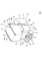
次に、図9に示す基板実装用コネクタの構成について説明する。 <Fourth embodiment>
Next, the configuration of the board mounting connector shown in FIG. 9 will be described.
次に、図9に示す基板実装用コネクタの構成について説明する。 <Fourth embodiment>
Next, the configuration of the board mounting connector shown in FIG. 9 will be described.
図9に示す基板実装用コネクタのシールドシェル70は、シールドシェル40と同様に、方形板部41と、3つの板部42,43,44とを含む。3つの板部42,43,44は、方形板部41の3辺から同じ方向に折り曲げられた板部である。隣り合う板部42と板部43は間隙を介して稜49aを形成している。隣り合う板部44と板部43は間隙を介して稜49bを形成している。第4実施形態では、シールドシェル70がハウジング20に取り付けられている状態において、方形板部41は、本体部21の背面21bと対向する。
9, similarly to the shield shell 40, the shield shell 70 of the board mounting connector includes a rectangular plate portion 41 and three plate portions 42, 43, and 44. The three plate portions 42, 43, 44 are plate portions that are bent in the same direction from the three sides of the rectangular plate portion 41. Adjacent plate portion 42 and plate portion 43 form a ridge 49a via a gap. Adjacent plate portion 44 and plate portion 43 form a ridge 49b through a gap. In the fourth embodiment, the rectangular plate portion 41 faces the back surface 21 b of the main body portion 21 in a state where the shield shell 70 is attached to the housing 20.
シールドシェル40と同様に、2個の延長片45が板部43に形成されており、1個の突出部46が板部42に形成されており、1個の突出部46が板部44に形成されている。ハウジング20の長さ方向に延びる一方の溝28がハウジング20の一方の受部22に形成されており、同様に、ハウジング20の長さ方向に延びる他方の溝28が他方の受部22に形成されている。上面21fから所定の深さまで2個の溝29が、ハウジング20の本体部21に、高さ方向(ただし、高さ方向は、上面21fと底面21cが対向する方向である)に沿って形成されている。2個の溝29の位置は、板部42,44の前端(先端)の位置に対応している。
Similar to the shield shell 40, two extension pieces 45 are formed on the plate portion 43, one protrusion 46 is formed on the plate portion 42, and one protrusion 46 is formed on the plate portion 44. Is formed. One groove 28 extending in the length direction of the housing 20 is formed in one receiving portion 22 of the housing 20. Similarly, the other groove 28 extending in the length direction of the housing 20 is formed in the other receiving portion 22. Has been. Two grooves 29 from the upper surface 21f to a predetermined depth are formed in the main body portion 21 of the housing 20 along the height direction (however, the height direction is a direction in which the upper surface 21f and the bottom surface 21c face each other). ing. The positions of the two grooves 29 correspond to the positions of the front ends (tips) of the plate portions 42 and 44.
シールドシェル70は、ハウジング20の上方からハウジング20に取り付けられる。板部42の前端は一方の溝29に挿入され、板部44の前端は他方の溝29に挿入される。板部42の後端の下部は一方の受部22の溝28に挿入され、板部44の後端の下部は他方の受部22の溝28に挿入される。第4実施形態では、溝29の外側の壁面である押圧壁面29aが突出部46を押圧する。突出部46の下面は、傾斜面46aである。接地端子47は板部42の下端に形成されており、同様に、接地端子47は板部44の下端に形成されている。
The shield shell 70 is attached to the housing 20 from above the housing 20. The front end of the plate portion 42 is inserted into one groove 29, and the front end of the plate portion 44 is inserted into the other groove 29. The lower portion of the rear end of the plate portion 42 is inserted into the groove 28 of one receiving portion 22, and the lower portion of the rear end of the plate portion 44 is inserted into the groove 28 of the other receiving portion 22. In the fourth embodiment, the pressing wall surface 29 a that is the outer wall surface of the groove 29 presses the protruding portion 46. The lower surface of the protrusion 46 is an inclined surface 46a. The ground terminal 47 is formed at the lower end of the plate portion 42, and similarly, the ground terminal 47 is formed at the lower end of the plate portion 44.
第4実施形態では、ハウジング20の本体部21の上面21fに対向する板部43と側面21dに対向する板部42との間に一方の短絡経路が形成され、さらに、ハウジング20の本体部21の上面21fに対向する板部43と側面21eに対向する板部44との間に他方の短絡経路が形成される。この構成の場合、上面21f側の板部43が外部から受けるノイズを、方形板部41を経由せずに、短い導電経路で接地端子47に導くことができる。
In the fourth embodiment, one short-circuit path is formed between the plate portion 43 facing the upper surface 21 f of the main body portion 21 of the housing 20 and the plate portion 42 facing the side surface 21 d, and further, the main body portion 21 of the housing 20. The other short-circuit path is formed between the plate portion 43 facing the upper surface 21f and the plate portion 44 facing the side surface 21e. In the case of this configuration, the noise received from the outside by the plate portion 43 on the upper surface 21 f side can be guided to the ground terminal 47 through a short conductive path without passing through the rectangular plate portion 41.
第4実施形態では、板部42または板部44が第1の板部に相当し、板部43が第2の板部に相当する。第4実施形態では、第1の板部の内側板面の一部位が第1の接触部に相当し、第1の板部に対応する延長片45の外側板面の一部位が第2の接触部に相当し、ハウジング20の一部位である押圧壁面29aが押圧部に相当する。さらに、第4実施形態では、第1の接触部と異なる第1の板部の一部位である突出部46が被押圧部に相当する。
In the fourth embodiment, the plate portion 42 or the plate portion 44 corresponds to the first plate portion, and the plate portion 43 corresponds to the second plate portion. In the fourth embodiment, one portion of the inner plate surface of the first plate portion corresponds to the first contact portion, and one portion of the outer plate surface of the extension piece 45 corresponding to the first plate portion is the second portion. The pressing wall surface 29a, which corresponds to the contact portion and is a part of the housing 20, corresponds to the pressing portion. Furthermore, in 4th Embodiment, the protrusion part 46 which is one site | part of the 1st board part different from a 1st contact part corresponds to a to-be-pressed part.
<変形例>
上述した各実施形態では、シールドシェルにおいて、稜を挟んで隣り合う板部の一方に延長片が形成されており、他方に押圧部によって押圧される被押圧部が形成されている。したがって、一方の接触部である延長片と、他方の接触部である内側板面(ただし、この内側板面は、突出部が形成されている板部の内側の板面である)と、によって短絡経路が構成される。しかし、短絡経路の構成はこの構成に限られない。以下、図10及び図11を参照して他の構成を説明する。 <Modification>
In each of the above-described embodiments, in the shield shell, an extension piece is formed on one of the adjacent plate portions across the ridge, and a pressed portion that is pressed by the pressing portion is formed on the other side. Therefore, by the extension piece that is one contact portion and the inner plate surface that is the other contact portion (however, this inner plate surface is the inner plate surface of the plate portion on which the protruding portion is formed). A short circuit path is constructed. However, the configuration of the short circuit path is not limited to this configuration. Hereinafter, another configuration will be described with reference to FIGS. 10 and 11.
<第1変形例>
図10に示すシールドシェル80では、板部43に形成されている一方の延長片45は、一方の延長片45のエッジから、一方の延長片45の伸長方向と直交する方向に伸長する一方の延長部81を含み、同様に、他方の延長片45は、他方の延長片45のエッジから、他方の延長片45の伸長方向と直交する方向に伸長する他方の延長部81を含む。各延長部81は、U字状の折り曲げ形状を有する。一方の延長部81の底部は、直近の板部42の下側を回り込んでおり、他方の延長部81の底部は、直近の板部44の下側を回り込んでいる。一方の延長部81の一端部は、板部42の外側に位置し、他方の延長部81の一端部は、板部44の外側に位置する。 <First Modification>
In theshield shell 80 shown in FIG. 10, one extension piece 45 formed on the plate portion 43 extends from the edge of the one extension piece 45 in a direction orthogonal to the extension direction of the one extension piece 45. Similarly, the other extension piece 45 includes the other extension part 81 extending from the edge of the other extension piece 45 in a direction perpendicular to the extension direction of the other extension piece 45. Each extension portion 81 has a U-shaped bent shape. The bottom portion of one extension portion 81 wraps around the lower side of the nearest plate portion 42, and the bottom portion of the other extension portion 81 wraps around the lower side of the nearest plate portion 44. One end portion of one extension portion 81 is located outside the plate portion 42, and one end portion of the other extension portion 81 is located outside the plate portion 44.
図10に示すシールドシェル80では、板部43に形成されている一方の延長片45は、一方の延長片45のエッジから、一方の延長片45の伸長方向と直交する方向に伸長する一方の延長部81を含み、同様に、他方の延長片45は、他方の延長片45のエッジから、他方の延長片45の伸長方向と直交する方向に伸長する他方の延長部81を含む。各延長部81は、U字状の折り曲げ形状を有する。一方の延長部81の底部は、直近の板部42の下側を回り込んでおり、他方の延長部81の底部は、直近の板部44の下側を回り込んでいる。一方の延長部81の一端部は、板部42の外側に位置し、他方の延長部81の一端部は、板部44の外側に位置する。 <First Modification>
In the
各延長部81について、延長部81の一端部は挿入部82であり、挿入部82の先端に、外向きにわずかに折り曲げられた折り曲げ部82aが形成されている。
For each extension part 81, one end of the extension part 81 is an insertion part 82, and a bent part 82a that is slightly bent outward is formed at the tip of the insertion part 82.
一方の挿入部82は、シールドシェル80がハウジング20に取り付けられている状態において、板部42とハウジング20に形成されている押圧部との隙間に位置する。同様に、他方の挿入部82は、シールドシェル80がハウジング20に取り付けられている状態において、板部44とハウジング20に形成されている押圧部との隙間に位置する。一方の折り曲げ部82aが押圧部によって押圧されることによって一方の挿入部82は変位し、この結果、一方の挿入部82は板部42と接触する。同様に、他方の折り曲げ部82aが押圧部によって押圧されることによって他方の挿入部82は変位し、この結果、他方の挿入部82は板部44と接触する。これによって、板部43と板部42との間に一方の短絡経路が形成され、さらに、板部43と板部44との間に他方の短絡経路が形成される。
One insertion portion 82 is located in a gap between the plate portion 42 and the pressing portion formed in the housing 20 in a state where the shield shell 80 is attached to the housing 20. Similarly, the other insertion portion 82 is located in a gap between the plate portion 44 and the pressing portion formed in the housing 20 in a state where the shield shell 80 is attached to the housing 20. When one bent portion 82a is pressed by the pressing portion, the one insertion portion 82 is displaced, and as a result, the one insertion portion 82 comes into contact with the plate portion 42. Similarly, when the other bent portion 82 a is pressed by the pressing portion, the other insertion portion 82 is displaced, and as a result, the other insertion portion 82 comes into contact with the plate portion 44. As a result, one short circuit path is formed between the plate part 43 and the plate part 42, and the other short circuit path is formed between the plate part 43 and the plate part 44.
第1変形例では、板部42または板部44が第1の板部に相当し、板部43が第2の板部に相当する。第1変形例では、第1の板部の外側板面の一部位が第1の接触部に相当し、第1の板部に対応する挿入部82の一部位(内側側面)が第2の接触部に相当し、ハウジング20の一部位である押圧壁面が押圧部に相当する。さらに、第1変形例では、第2の接触部と異なる第1の延長片の一部位(具体的には、折り曲げ部82a)が被押圧部に相当する。つまり、第2の接触部および被押圧部は挿入部に位置する。
In the first modification, the plate portion 42 or the plate portion 44 corresponds to the first plate portion, and the plate portion 43 corresponds to the second plate portion. In the first modification, one portion of the outer plate surface of the first plate portion corresponds to the first contact portion, and one portion (inner side surface) of the insertion portion 82 corresponding to the first plate portion is the second. The pressing wall surface corresponding to the contact portion and one part of the housing 20 corresponds to the pressing portion. Furthermore, in the first modified example, one part (specifically, the bent part 82a) of the first extension piece different from the second contact part corresponds to the pressed part. That is, the second contact part and the pressed part are located in the insertion part.
<第2変形例>
図11に示すシールドシェル90では、1個の延長片91が板部42に形成されており、同様に、1個の延長片91が板部44に形成されている。各延長部91は、U字状の折り曲げ形状を有する。板部43に形成されている2個の延長片45はそれぞれ、直角に折り曲げられている。一方の延長片45は板部42の外側板面に対向しており、他方の延長片45は板部44の外側板面に対向している。一方の延長片91の底部は一方の延長片45の下側を回り込んでおり、他方の延長片91の底部は他方の延長片45の下側を回り込んでいる。一方の延長部91の一端部は一方の延長片45の外側に位置し、他方の延長部91の一端部は他方の延長片45の外側に位置する。 <Second Modification>
In theshield shell 90 shown in FIG. 11, one extension piece 91 is formed on the plate portion 42, and similarly, one extension piece 91 is formed on the plate portion 44. Each extension 91 has a U-shaped bent shape. Each of the two extension pieces 45 formed on the plate portion 43 is bent at a right angle. One extension piece 45 faces the outer plate surface of the plate portion 42, and the other extension piece 45 faces the outer plate surface of the plate portion 44. The bottom part of one extension piece 91 wraps around the lower side of one extension piece 45, and the bottom part of the other extension piece 91 wraps around the lower side of the other extension piece 45. One end of one extension 91 is located outside one extension piece 45, and one end of the other extension 91 is located outside the other extension piece 45.
図11に示すシールドシェル90では、1個の延長片91が板部42に形成されており、同様に、1個の延長片91が板部44に形成されている。各延長部91は、U字状の折り曲げ形状を有する。板部43に形成されている2個の延長片45はそれぞれ、直角に折り曲げられている。一方の延長片45は板部42の外側板面に対向しており、他方の延長片45は板部44の外側板面に対向している。一方の延長片91の底部は一方の延長片45の下側を回り込んでおり、他方の延長片91の底部は他方の延長片45の下側を回り込んでいる。一方の延長部91の一端部は一方の延長片45の外側に位置し、他方の延長部91の一端部は他方の延長片45の外側に位置する。 <Second Modification>
In the
各延長部91について、延長片91の一端部は挿入部92であり、挿入部92の先端に、外向きにわずかに折り曲げられた折り曲げ部92aが形成されている。
For each extension 91, one end of the extension piece 91 is an insertion portion 92, and a bent portion 92 a that is slightly bent outward is formed at the tip of the insertion portion 92.
一方の挿入部92は、シールドシェル90がハウジング20に取り付けられている状態において、一方の延長片45とハウジング20に形成されている押圧部との隙間に位置する。同様に、他方の挿入部92は、シールドシェル90がハウジング20に取り付けられている状態において、他方の延長片45とハウジング20に形成されている押圧部との隙間に位置する。一方の折り曲げ部92aが押圧部によって押圧されることによって一方の挿入部92は変位し、この結果、一方の挿入部92は一方の延長片45と接触する。同様に、他方の折り曲げ部92aが押圧部によって押圧されることによって他方の挿入部92は変位し、この結果、他方の挿入部92は他方の延長片45と接触する。これによって、板部43と板部42との間に一方の短絡経路が形成され、さらに、板部43と板部44との間に他方の短絡経路が形成される。
The one insertion portion 92 is located in a gap between the one extension piece 45 and the pressing portion formed in the housing 20 in a state where the shield shell 90 is attached to the housing 20. Similarly, the other insertion portion 92 is located in a gap between the other extension piece 45 and the pressing portion formed in the housing 20 in a state where the shield shell 90 is attached to the housing 20. When the one bent portion 92a is pressed by the pressing portion, the one insertion portion 92 is displaced, and as a result, the one insertion portion 92 contacts the one extension piece 45. Similarly, when the other bent portion 92 a is pressed by the pressing portion, the other insertion portion 92 is displaced, and as a result, the other insertion portion 92 comes into contact with the other extension piece 45. As a result, one short circuit path is formed between the plate part 43 and the plate part 42, and the other short circuit path is formed between the plate part 43 and the plate part 44.
第2変形例では、板部42または板部44が第1の板部に相当し、板部43が第2の板部に相当する。第2変形例では、第1の板部に対応する挿入部92の一部位(内側側面)が第1の接触部に相当し、第1の板部に対応する延長片45の外側側面の一部位が第2の接触部に相当し、ハウジング20の一部位である押圧壁面が押圧部に相当する。さらに、第2変形例では、第1の接触部と異なる第2の延長片の一部位(具体的には、折り曲げ部92a)が被押圧部に相当する。つまり、第1の接触部および被押圧部は第2の延長片に位置する。
In the second modification, the plate portion 42 or the plate portion 44 corresponds to the first plate portion, and the plate portion 43 corresponds to the second plate portion. In the second modification, one portion (inner side surface) of the insertion portion 92 corresponding to the first plate portion corresponds to the first contact portion, and one portion of the outer side surface of the extension piece 45 corresponding to the first plate portion. The part corresponds to the second contact part, and the pressing wall surface which is one part of the housing 20 corresponds to the pressing part. Furthermore, in the second modified example, one portion (specifically, the bent portion 92a) of the second extension piece different from the first contact portion corresponds to the pressed portion. That is, the first contact portion and the pressed portion are located on the second extension piece.
<補記>
上述の各実施形態および各変形例では、被押圧部を押圧することによって、隣り合うシールドシェルの板面を短絡させるための押圧部(押圧壁面)は、シールドシェルがハウジングに取り付けられている状態においてシールドシェルの外側に位置しており、被押圧部を内向きに押圧する。もちろん、このような構成に限定されず、例えば、押圧部が外向きに被押圧部を押圧する構成を採用することも許容される。ただし、接触部の露出の防止およびシールドシェルの拡幅変形を防ぐ観点から、内向きに被押圧部を押圧する構成が好ましい。押圧部は溝の壁面に限定されず、受部の溝構造は必須構成要素ではない。 <Supplementary note>
In each of the above-described embodiments and modifications, the pressing portion (pressing wall surface) for short-circuiting the plate surfaces of adjacent shield shells by pressing the pressed portion is a state where the shield shell is attached to the housing. Is located outside the shield shell and presses the pressed portion inward. Of course, it is not limited to such a configuration, and, for example, it is allowed to employ a configuration in which the pressing portion presses the pressed portion outward. However, the structure which presses a to-be-pressed part inward from a viewpoint of preventing exposure of a contact part and preventing the widening deformation | transformation of a shield shell is preferable. The pressing portion is not limited to the wall surface of the groove, and the groove structure of the receiving portion is not an essential component.
上述の各例では、シールドシェルが、方形板部41と、方形板部41の3辺から同じ方向に直角に折り曲げられた3つの板部を有しており、3つの板部のうち隣り合う板部が稜を形成する。しかし、本発明はこのような構成に限定されない。例えば、方形板部を持たないシールドシェル、あるいは、大きな曲率半径を持つ曲げに連なる板部を有するシールドシェルも許容される。
In each of the above-described examples, the shield shell has the rectangular plate portion 41 and three plate portions bent at right angles in the same direction from the three sides of the rectangular plate portion 41, and is adjacent to the three plate portions. The plate portion forms a ridge. However, the present invention is not limited to such a configuration. For example, a shield shell having no square plate portion or a shield shell having a plate portion connected to a bend having a large radius of curvature is allowed.
導電経路の短縮の観点からは、第1の接触部と第2の接触部は、方形板部から離れた部位(例えば、対応する板部の辺縁部あるいは辺縁部の近傍)に位置することが好ましい。
From the viewpoint of shortening the conductive path, the first contact portion and the second contact portion are located at a portion away from the rectangular plate portion (for example, the edge portion of the corresponding plate portion or the vicinity of the edge portion). It is preferable.
さらに、コンタクトに流れる高周波信号の外部への輻射を防止する観点からは、第1の板部と第2の板部のうち一方はコンタクトに対向しており、第1の板部と第2の板部のうち他方は接地端子が形成されている構成が好ましい。
Furthermore, from the viewpoint of preventing radiation of the high-frequency signal flowing through the contact, one of the first plate portion and the second plate portion faces the contact, and the first plate portion and the second plate portion A configuration in which a ground terminal is formed on the other of the plate portions is preferable.
上述の各例では、分かり易い説明の観点から、シールドシェルがコンタクトの脚部からノイズを受ける状況を説明した。しかし、シールドシェルが受けるノイズは、コンタクトの脚部から受けるノイズに限定されない。シールドシェルは、例えばシールドシェルの外部からもノイズを受ける。ノイズ源を限定しない場合の本発明の利点についての説明を追加する。
第1の板部とシールドシェルの接地端子との距離L1と、第2の板部とシールドシェルの接地端子との距離L2について、実際に製造されるコネクタでは、L1>L2またはL2>L1が成立する。L1>L2の場合を説明する。
シールドシェルがノイズを受ける場合、一般的に、第1の板部が受けるノイズが完全にゼロであることは無い。この点、本発明によると、第1の板部のゼロでないノイズが流れることのできる、第1の板部と第2の板部を橋渡しする導電経路(L1よりも短い導電経路)が提供されているので、本発明の基板実装用コネクタは良好なシールド性能を有する。
L2>L1の場合も同様である。 In each of the above examples, the situation where the shield shell receives noise from the leg portion of the contact has been described from the viewpoint of easy explanation. However, the noise received by the shield shell is not limited to the noise received from the leg portion of the contact. The shield shell receives noise from the outside of the shield shell, for example. A description of the advantages of the present invention when the noise source is not limited will be added.
With respect to the distance L1 between the first plate portion and the ground terminal of the shield shell and the distance L2 between the second plate portion and the ground terminal of the shield shell, L1> L2 or L2> L1 in the actually manufactured connector To establish. A case where L1> L2 will be described.
When the shield shell receives noise, generally, the noise received by the first plate portion is not completely zero. In this regard, according to the present invention, there is provided a conductive path (a conductive path shorter than L1) that bridges the first plate portion and the second plate portion through which non-zero noise of the first plate portion can flow. Therefore, the board mounting connector of the present invention has a good shielding performance.
The same applies to L2> L1.
本発明において、接地端子47だけでなく、ハウジング20の上面21fと対向するシールドシェルの板部も接地される実施形態も許される。接地の構成に限定は無く、一例として、ハウジング20の上面21fと対向するシールドシェルの板部に形成された接地端子が筐体に接続するフレームグラウンドを例示できる。接地端子47は、基板上の接地パターンではなく、筐体に接続してもよい。
In the present invention, not only the ground terminal 47 but also the shield shell plate facing the upper surface 21f of the housing 20 may be grounded. There is no limitation on the configuration of grounding. As an example, a frame ground in which a grounding terminal formed on the plate portion of the shield shell facing the upper surface 21f of the housing 20 is connected to the housing can be exemplified. The ground terminal 47 may be connected to the housing instead of the ground pattern on the substrate.
本発明によれば、ハウジングに取り付けられているシールドシェルにおいて、間隙を介して隣り合う板部の間に短絡経路を形成できる。この短絡経路は、シールドシェルにおいてノイズが流れる導電経路として機能する。つまり、従来例では連続した板面内だけにノイズの流れる導電経路が形成されたが、本発明によると、連続しない板面間に新たな導電経路が提供されるので、より良好なシールド性能を有する基板実装用コネクタが実現する。
According to the present invention, in the shield shell attached to the housing, a short-circuit path can be formed between adjacent plate portions with a gap therebetween. This short circuit path functions as a conductive path through which noise flows in the shield shell. In other words, in the conventional example, a conductive path through which noise flows is formed only within a continuous plate surface, but according to the present invention, a new conductive path is provided between non-continuous plate surfaces, so that better shielding performance can be achieved. The board mounting connector is realized.
また、本発明によると、小型化と良好なシールド性能とを両立する基板実装用コネクタを実現できる場合がある。従来のコネクタでは、コネクタの小型化を実現できる接地端子の位置では良好なシールド性能(短い導電経路)を達成できず、良好なシールド性能(短い導電経路)を達成できる接地端子の位置ではコネクタの小型化を実現できない、というトレードオフの関係が生じる場合があった。しかし、本発明によると、第1の板部と第2の板部を橋渡しする導電経路が提供されているので、コネクタの小型化を実現できる接地端子の位置で良好なシールド性能(短い導電経路)を達成できる場合がある。
In addition, according to the present invention, there may be a case where a board mounting connector that achieves both miniaturization and good shielding performance can be realized. With conventional connectors, good shielding performance (short conductive path) cannot be achieved at the position of the ground terminal where the connector can be miniaturized, and at the position of the ground terminal where good shielding performance (short conductive path) can be achieved. In some cases, there was a trade-off relationship that miniaturization could not be realized. However, according to the present invention, since a conductive path that bridges the first plate portion and the second plate portion is provided, good shielding performance (short conductive path) can be achieved at the position of the ground terminal that can realize miniaturization of the connector. ) May be achieved.
以上、本発明の実施形態について説明したが、本発明はこれらの実施形態に限定されるものではない。本発明の要旨を逸脱しない範囲において種々の変更と変形が許される。選択され且つ説明された実施形態は、本発明の原理およびその実際的応用を解説するためのものである。本発明は様々な変更あるいは変形を伴って様々な実施形態として使用され、様々な変更あるいは変形は期待される用途に応じて決定される。そのような変更および変形のすべては、添付の請求範囲によって定義される本発明の範囲に含まれることが意図されており、公平、適法および公正に与えられる広さに従って解釈される場合、同じ保護が与えられることが意図されている。
The embodiments of the present invention have been described above, but the present invention is not limited to these embodiments. Various changes and modifications are allowed without departing from the scope of the present invention. The selected and described embodiments are intended to illustrate the principles of the invention and its practical application. The present invention is used as various embodiments with various changes or modifications, and various changes or modifications are determined according to the expected application. All such modifications and variations are intended to be included within the scope of the present invention as defined by the appended claims and, when interpreted according to fairness, lawfulness and the breadth afforded fairly, the same protection Is intended to be given.
Claims (10)
- 基板実装用コネクタであって、
絶縁体で形成されたハウジングと、
上記ハウジングに取り付けられているコンタクトと、
金属板で形成されているシールドシェルと
を含み、
上記シールドシェルは、上記ハウジングに取り付けられており、上記コンタクトを覆っており、
上記シールドシェルは、隣り合う第1の板部と第2の板部を含み、
上記シールドシェルが上記ハウジングに取り付けられていない状態において、上記第1の板部は上記第2の板部に接触しておらず、
上記第1の板部の一部位は、第1の接触部であり、
第1の延長片が、上記第2の板部に形成されており、
上記第1の延長片の一部位は、第2の接触部であり、
上記ハウジングの一部位は、上記シールドシェルが上記ハウジングに取り付けられている状態において上記第1の板部に対向する押圧部であり、
上記第1の接触部と異なる上記第1の板部の一部位、または、上記第2の接触部と異なる上記第1の延長片の一部位は、上記シールドシェルが上記ハウジングに取り付けられている状態において上記押圧部によって押圧される被押圧部であり、
上記シールドシェルが上記ハウジングに取り付けられることによって上記押圧部が上記被押圧部を押圧し、上記第1の接触部が上記第2の接触部に接触する。 A board mounting connector,
A housing formed of an insulator;
A contact attached to the housing;
Including a shield shell formed of a metal plate,
The shield shell is attached to the housing and covers the contact;
The shield shell includes a first plate portion and a second plate portion adjacent to each other,
In a state where the shield shell is not attached to the housing, the first plate portion is not in contact with the second plate portion,
One part of the first plate part is a first contact part,
A first extension piece is formed on the second plate portion;
One part of the first extension piece is a second contact portion,
One portion of the housing is a pressing portion facing the first plate portion in a state where the shield shell is attached to the housing,
The shield shell is attached to the housing at a part of the first plate part different from the first contact part or a part of the first extension piece different from the second contact part. A pressed part pressed by the pressing part in the state,
When the shield shell is attached to the housing, the pressing portion presses the pressed portion, and the first contact portion contacts the second contact portion. - 請求項1に記載の基板実装用コネクタにおいて、
上記押圧部は、上記シールドシェルが上記ハウジングに取り付けられている状態において上記シールドシェルの外側に位置しており、
上記シールドシェルが上記ハウジングに取り付けられることによって上記押圧部が上記被押圧部を内向きに押圧する。 The board mounting connector according to claim 1,
The pressing portion is located outside the shield shell in a state where the shield shell is attached to the housing,
When the shield shell is attached to the housing, the pressing portion presses the pressed portion inward. - 請求項1または請求項2に記載の基板実装用コネクタにおいて、
上記被押圧部は、上記第1の板部の板面に形成された突出部である、ただし、当該板面は上記押圧部に対向する板面である。 In the board mounting connector according to claim 1 or 2,
The pressed portion is a protruding portion formed on the plate surface of the first plate portion. However, the plate surface is a plate surface facing the pressing portion. - 請求項1または請求項2に記載の基板実装用コネクタにおいて、
上記第1の延長片は、上記シールドシェルが上記ハウジングに取り付けられている状態において上記第1の板部と上記押圧部との隙間に位置する挿入部を有し、
上記第2の接触部および上記被押圧部が上記挿入部に位置する。 In the board mounting connector according to claim 1 or 2,
The first extension piece has an insertion portion located in a gap between the first plate portion and the pressing portion in a state where the shield shell is attached to the housing.
The second contact part and the pressed part are located in the insertion part. - 請求項1または請求項2に記載の基板実装用コネクタにおいて、
上記シールドシェルが上記ハウジングに取り付けられている状態において上記第1の延長片と上記押圧部との隙間に位置する第2の延長片が、上記第1の板部に形成されており、
上記第1の接触部および上記被押圧部が上記第2の延長片に位置する。 In the board mounting connector according to claim 1 or 2,
In the state where the shield shell is attached to the housing, a second extension piece located in a gap between the first extension piece and the pressing portion is formed on the first plate portion,
The first contact portion and the pressed portion are located on the second extension piece. - 請求項1から請求項5のいずれかに記載の基板実装用コネクタにおいて、
上記シールドシェルは、方形板部と3個の板部を含み、
上記3個の板部は、上記方形板部の3辺から同じ方向に折り曲げられており、
上記3個の板部のうち隣り合う2個の板部は稜を形成しており、
上記第1の板部と上記第2の板部は、上記3個の板部のうち隣り合う2個の板部である。 In the board mounting connector according to any one of claims 1 to 5,
The shield shell includes a rectangular plate portion and three plate portions,
The three plate portions are bent in the same direction from the three sides of the rectangular plate portion,
Two adjacent plate portions among the three plate portions form a ridge,
The first plate portion and the second plate portion are two adjacent plate portions among the three plate portions. - 請求項6に記載の基板実装用コネクタにおいて、
上記方形板部は、基板に実装される側の上記ハウジングの面と反対側の上記ハウジングの面に対向する。 The board mounting connector according to claim 6,
The rectangular plate portion faces a surface of the housing opposite to the surface of the housing on the side mounted on the substrate. - 請求項6に記載の基板実装用コネクタにおいて、
上記方形板部は、上記基板実装用コネクタに接続するコネクタとの接続側の上記ハウジングの面と反対側の上記ハウジングの面に対向する。 The board mounting connector according to claim 6,
The rectangular plate portion faces the surface of the housing opposite to the surface of the housing on the connection side with the connector connected to the board mounting connector. - 請求項6に記載の基板実装用コネクタにおいて、
上記第1の接触部は、上記第1の板部において、上記方形板部から離れた部位に位置し、
上記第2の接触部は、上記第2の板部において、上記方形板部から離れた部位に位置する。 The board mounting connector according to claim 6,
The first contact portion is located at a position away from the rectangular plate portion in the first plate portion,
The second contact portion is located at a position away from the rectangular plate portion in the second plate portion. - 請求項1から請求項9のいずれかに記載の基板実装用コネクタにおいて、
上記第1の板部と上記第2の板部のうち一方は、上記コンタクトに対向しており、
上記第1の板部と上記第2の板部のうち他方は、接地端子が形成されている。 In the board mounting connector according to any one of claims 1 to 9,
One of the first plate portion and the second plate portion faces the contact,
The other of the first plate portion and the second plate portion has a ground terminal.
Priority Applications (3)
| Application Number | Priority Date | Filing Date | Title |
|---|---|---|---|
| CN201880013037.4A CN110313108B (en) | 2017-02-23 | 2018-02-16 | Connector for mounting substrate |
| US16/486,669 US10978817B2 (en) | 2017-02-23 | 2018-02-16 | Connector for mounting to a substrate |
| EP18757042.9A EP3588694A4 (en) | 2017-02-23 | 2018-02-16 | Connector for base board mounting use |
Applications Claiming Priority (2)
| Application Number | Priority Date | Filing Date | Title |
|---|---|---|---|
| JP2017-031682 | 2017-02-23 | ||
| JP2017031682A JP6325706B1 (en) | 2017-02-23 | 2017-02-23 | Board mounting connector |
Publications (1)
| Publication Number | Publication Date |
|---|---|
| WO2018155330A1 true WO2018155330A1 (en) | 2018-08-30 |
Family
ID=62143939
Family Applications (1)
| Application Number | Title | Priority Date | Filing Date |
|---|---|---|---|
| PCT/JP2018/005437 WO2018155330A1 (en) | 2017-02-23 | 2018-02-16 | Connector for base board mounting use |
Country Status (5)
| Country | Link |
|---|---|
| US (1) | US10978817B2 (en) |
| EP (1) | EP3588694A4 (en) |
| JP (1) | JP6325706B1 (en) |
| CN (1) | CN110313108B (en) |
| WO (1) | WO2018155330A1 (en) |
Families Citing this family (1)
| Publication number | Priority date | Publication date | Assignee | Title |
|---|---|---|---|---|
| CN212542862U (en) * | 2020-06-30 | 2021-02-12 | 瑞声精密制造科技(常州)有限公司 | A kind of interface unit |
Citations (5)
| Publication number | Priority date | Publication date | Assignee | Title |
|---|---|---|---|---|
| JP2008041419A (en) * | 2006-08-07 | 2008-02-21 | Nintendo Co Ltd | Connector |
| JP2013004437A (en) * | 2011-06-21 | 2013-01-07 | Yazaki Corp | Substrate mounting component and substrate mounting component manufacturing method |
| JP2014041797A (en) | 2012-08-23 | 2014-03-06 | Smk Corp | Receptacle connector |
| JP2015176657A (en) * | 2014-03-13 | 2015-10-05 | ホシデン株式会社 | connector |
| JP2016018589A (en) * | 2014-07-04 | 2016-02-01 | 日本航空電子工業株式会社 | connector |
Family Cites Families (16)
| Publication number | Priority date | Publication date | Assignee | Title |
|---|---|---|---|---|
| DE4410072A1 (en) * | 1993-03-26 | 1994-09-29 | Whitaker Corp | Coaxial cable plug connector arrangement |
| US6139367A (en) * | 1999-08-03 | 2000-10-31 | Hon Hai Precision Ind. Co., Ltd. | Shielded electrical connector |
| US6354875B1 (en) * | 2000-10-10 | 2002-03-12 | Hon Hai Precision Ind. Co., Ltd. | Electrical connector with a rear shield |
| KR100480884B1 (en) * | 2001-05-25 | 2005-04-06 | 마츠시다 덴코 가부시키가이샤 | Connector |
| CN2651987Y (en) * | 2003-07-31 | 2004-10-27 | 富士康(昆山)电脑接插件有限公司 | Electric connector |
| CN2674699Y (en) * | 2003-11-06 | 2005-01-26 | 富士康(昆山)电脑接插件有限公司 | Electric connector |
| JP4576226B2 (en) * | 2004-12-28 | 2010-11-04 | ホシデン株式会社 | Coaxial connector integrated board connection connector |
| US7168987B1 (en) | 2005-07-12 | 2007-01-30 | Fujitsu Component Limited | Right angle type connector used for balanced transmission of data signals |
| US7351105B2 (en) * | 2005-11-09 | 2008-04-01 | Molex Incorporated | Board mounted shielded electrical connector |
| JP4199272B2 (en) * | 2006-08-23 | 2008-12-17 | 日本航空電子工業株式会社 | connector |
| JP5221188B2 (en) * | 2008-04-07 | 2013-06-26 | 矢崎総業株式会社 | Shield connector |
| JP4863317B2 (en) * | 2009-03-30 | 2012-01-25 | ヒロセ電機株式会社 | Circuit board electrical connector |
| TW201039513A (en) * | 2009-04-22 | 2010-11-01 | Advanced Connectek Inc | Electrical connector capable of eliminating interference |
| JP5622306B2 (en) * | 2010-07-05 | 2014-11-12 | 矢崎総業株式会社 | Board mounted connector |
| JP6078919B2 (en) * | 2013-07-18 | 2017-02-15 | ホシデン株式会社 | connector |
| JP6422815B2 (en) * | 2015-04-21 | 2018-11-14 | 日本航空電子工業株式会社 | connector |
-
2017
- 2017-02-23 JP JP2017031682A patent/JP6325706B1/en active Active
-
2018
- 2018-02-16 CN CN201880013037.4A patent/CN110313108B/en active Active
- 2018-02-16 EP EP18757042.9A patent/EP3588694A4/en not_active Withdrawn
- 2018-02-16 WO PCT/JP2018/005437 patent/WO2018155330A1/en unknown
- 2018-02-16 US US16/486,669 patent/US10978817B2/en active Active
Patent Citations (5)
| Publication number | Priority date | Publication date | Assignee | Title |
|---|---|---|---|---|
| JP2008041419A (en) * | 2006-08-07 | 2008-02-21 | Nintendo Co Ltd | Connector |
| JP2013004437A (en) * | 2011-06-21 | 2013-01-07 | Yazaki Corp | Substrate mounting component and substrate mounting component manufacturing method |
| JP2014041797A (en) | 2012-08-23 | 2014-03-06 | Smk Corp | Receptacle connector |
| JP2015176657A (en) * | 2014-03-13 | 2015-10-05 | ホシデン株式会社 | connector |
| JP2016018589A (en) * | 2014-07-04 | 2016-02-01 | 日本航空電子工業株式会社 | connector |
Non-Patent Citations (1)
| Title |
|---|
| See also references of EP3588694A4 |
Also Published As
| Publication number | Publication date |
|---|---|
| US10978817B2 (en) | 2021-04-13 |
| US20200059023A1 (en) | 2020-02-20 |
| EP3588694A1 (en) | 2020-01-01 |
| CN110313108A (en) | 2019-10-08 |
| EP3588694A4 (en) | 2020-03-04 |
| CN110313108B (en) | 2021-03-16 |
| JP2018137158A (en) | 2018-08-30 |
| JP6325706B1 (en) | 2018-05-16 |
Similar Documents
| Publication | Publication Date | Title |
|---|---|---|
| JP6806028B2 (en) | Multi-pole connector set | |
| TWI593192B (en) | Electrical connector | |
| US9972950B2 (en) | Shield case, and connector having the same | |
| US7104842B1 (en) | Electromagnetic interference diminishing structure of a connector assembly | |
| JP2622940B2 (en) | Shielded electrical connector assembly | |
| JP7348045B2 (en) | Mounting structure of board-to-board connector | |
| JP5221188B2 (en) | Shield connector | |
| KR102633728B1 (en) | Connector | |
| CN113675677A (en) | Connector assembly | |
| JP7417855B2 (en) | connector device | |
| KR102519889B1 (en) | Connector assembly | |
| JP7103510B2 (en) | Multi-pole connector set | |
| JP7180757B2 (en) | Multi-pole connector set | |
| JP4476311B2 (en) | connector | |
| WO2018155330A1 (en) | Connector for base board mounting use | |
| JPH10106684A (en) | Connector | |
| JP7348135B2 (en) | connector assembly | |
| JP2019129117A (en) | Shield connector | |
| TWM482867U (en) | A latching structure between electrical connectors | |
| JP7176631B2 (en) | Multi-pole connector and multi-pole connector set | |
| JP7461245B2 (en) | connector | |
| CN211958129U (en) | Electric connector structure and shielding rear cover thereof | |
| JP7051231B2 (en) | Board connector | |
| WO2022190986A1 (en) | Connector assembly | |
| WO2022190987A1 (en) | Connector assembly |
Legal Events
| Date | Code | Title | Description |
|---|---|---|---|
| 121 | Ep: the epo has been informed by wipo that ep was designated in this application |
Ref document number: 18757042 Country of ref document: EP Kind code of ref document: A1 |
|
| NENP | Non-entry into the national phase |
Ref country code: DE |
|
| ENP | Entry into the national phase |
Ref document number: 2018757042 Country of ref document: EP Effective date: 20190923 |