WO2018155267A1 - Image display device, image display method, and program - Google Patents
Image display device, image display method, and program Download PDFInfo
- Publication number
- WO2018155267A1 WO2018155267A1 PCT/JP2018/004962 JP2018004962W WO2018155267A1 WO 2018155267 A1 WO2018155267 A1 WO 2018155267A1 JP 2018004962 W JP2018004962 W JP 2018004962W WO 2018155267 A1 WO2018155267 A1 WO 2018155267A1
- Authority
- WO
- WIPO (PCT)
- Prior art keywords
- image
- display
- thermal
- thermal image
- visible
- Prior art date
Links
- 238000000034 method Methods 0.000 title claims description 15
- 230000010365 information processing Effects 0.000 claims description 34
- 239000003086 colorant Substances 0.000 abstract description 3
- 238000006243 chemical reaction Methods 0.000 description 7
- 238000013500 data storage Methods 0.000 description 7
- 238000003384 imaging method Methods 0.000 description 7
- 238000004891 communication Methods 0.000 description 6
- 238000010586 diagram Methods 0.000 description 6
- 238000005516 engineering process Methods 0.000 description 4
- 238000002405 diagnostic procedure Methods 0.000 description 3
- 230000020169 heat generation Effects 0.000 description 3
- 230000009467 reduction Effects 0.000 description 3
- 230000002159 abnormal effect Effects 0.000 description 2
- 238000007792 addition Methods 0.000 description 2
- 230000008859 change Effects 0.000 description 2
- 239000004065 semiconductor Substances 0.000 description 2
- 230000035945 sensitivity Effects 0.000 description 2
- 230000007704 transition Effects 0.000 description 2
- 238000009966 trimming Methods 0.000 description 2
- 238000004040 coloring Methods 0.000 description 1
- 230000007547 defect Effects 0.000 description 1
- 230000002950 deficient Effects 0.000 description 1
- 238000009826 distribution Methods 0.000 description 1
- 230000000694 effects Effects 0.000 description 1
- 239000000284 extract Substances 0.000 description 1
- 239000004973 liquid crystal related substance Substances 0.000 description 1
- 238000012986 modification Methods 0.000 description 1
- 230000004048 modification Effects 0.000 description 1
- 230000003287 optical effect Effects 0.000 description 1
- 238000003825 pressing Methods 0.000 description 1
- 230000008569 process Effects 0.000 description 1
- 230000005855 radiation Effects 0.000 description 1
- 238000003860 storage Methods 0.000 description 1
- 230000000007 visual effect Effects 0.000 description 1
- XLYOFNOQVPJJNP-UHFFFAOYSA-N water Substances O XLYOFNOQVPJJNP-UHFFFAOYSA-N 0.000 description 1
Images


Classifications
-
- G—PHYSICS
- G06—COMPUTING; CALCULATING OR COUNTING
- G06T—IMAGE DATA PROCESSING OR GENERATION, IN GENERAL
- G06T11/00—2D [Two Dimensional] image generation
- G06T11/001—Texturing; Colouring; Generation of texture or colour
-
- H—ELECTRICITY
- H04—ELECTRIC COMMUNICATION TECHNIQUE
- H04N—PICTORIAL COMMUNICATION, e.g. TELEVISION
- H04N21/00—Selective content distribution, e.g. interactive television or video on demand [VOD]
- H04N21/40—Client devices specifically adapted for the reception of or interaction with content, e.g. set-top-box [STB]; Operations thereof
- H04N21/43—Processing of content or additional data, e.g. demultiplexing additional data from a digital video stream; Elementary client operations, e.g. monitoring of home network or synchronising decoder's clock; Client middleware
- H04N21/431—Generation of visual interfaces for content selection or interaction; Content or additional data rendering
- H04N21/4312—Generation of visual interfaces for content selection or interaction; Content or additional data rendering involving specific graphical features, e.g. screen layout, special fonts or colors, blinking icons, highlights or animations
- H04N21/4316—Generation of visual interfaces for content selection or interaction; Content or additional data rendering involving specific graphical features, e.g. screen layout, special fonts or colors, blinking icons, highlights or animations for displaying supplemental content in a region of the screen, e.g. an advertisement in a separate window
-
- G—PHYSICS
- G01—MEASURING; TESTING
- G01D—MEASURING NOT SPECIALLY ADAPTED FOR A SPECIFIC VARIABLE; ARRANGEMENTS FOR MEASURING TWO OR MORE VARIABLES NOT COVERED IN A SINGLE OTHER SUBCLASS; TARIFF METERING APPARATUS; MEASURING OR TESTING NOT OTHERWISE PROVIDED FOR
- G01D7/00—Indicating measured values
-
- G—PHYSICS
- G01—MEASURING; TESTING
- G01J—MEASUREMENT OF INTENSITY, VELOCITY, SPECTRAL CONTENT, POLARISATION, PHASE OR PULSE CHARACTERISTICS OF INFRARED, VISIBLE OR ULTRAVIOLET LIGHT; COLORIMETRY; RADIATION PYROMETRY
- G01J5/00—Radiation pyrometry, e.g. infrared or optical thermometry
- G01J5/02—Constructional details
- G01J5/025—Interfacing a pyrometer to an external device or network; User interface
-
- G—PHYSICS
- G01—MEASURING; TESTING
- G01J—MEASUREMENT OF INTENSITY, VELOCITY, SPECTRAL CONTENT, POLARISATION, PHASE OR PULSE CHARACTERISTICS OF INFRARED, VISIBLE OR ULTRAVIOLET LIGHT; COLORIMETRY; RADIATION PYROMETRY
- G01J5/00—Radiation pyrometry, e.g. infrared or optical thermometry
- G01J5/48—Thermography; Techniques using wholly visual means
-
- G—PHYSICS
- G06—COMPUTING; CALCULATING OR COUNTING
- G06F—ELECTRIC DIGITAL DATA PROCESSING
- G06F3/00—Input arrangements for transferring data to be processed into a form capable of being handled by the computer; Output arrangements for transferring data from processing unit to output unit, e.g. interface arrangements
- G06F3/01—Input arrangements or combined input and output arrangements for interaction between user and computer
- G06F3/048—Interaction techniques based on graphical user interfaces [GUI]
- G06F3/0484—Interaction techniques based on graphical user interfaces [GUI] for the control of specific functions or operations, e.g. selecting or manipulating an object, an image or a displayed text element, setting a parameter value or selecting a range
-
- G—PHYSICS
- G06—COMPUTING; CALCULATING OR COUNTING
- G06T—IMAGE DATA PROCESSING OR GENERATION, IN GENERAL
- G06T5/00—Image enhancement or restoration
- G06T5/50—Image enhancement or restoration using two or more images, e.g. averaging or subtraction
-
- G—PHYSICS
- G06—COMPUTING; CALCULATING OR COUNTING
- G06T—IMAGE DATA PROCESSING OR GENERATION, IN GENERAL
- G06T7/00—Image analysis
- G06T7/90—Determination of colour characteristics
-
- H—ELECTRICITY
- H04—ELECTRIC COMMUNICATION TECHNIQUE
- H04N—PICTORIAL COMMUNICATION, e.g. TELEVISION
- H04N7/00—Television systems
- H04N7/18—Closed-circuit television [CCTV] systems, i.e. systems in which the video signal is not broadcast
-
- G—PHYSICS
- G01—MEASURING; TESTING
- G01J—MEASUREMENT OF INTENSITY, VELOCITY, SPECTRAL CONTENT, POLARISATION, PHASE OR PULSE CHARACTERISTICS OF INFRARED, VISIBLE OR ULTRAVIOLET LIGHT; COLORIMETRY; RADIATION PYROMETRY
- G01J5/00—Radiation pyrometry, e.g. infrared or optical thermometry
- G01J2005/0077—Imaging
-
- G—PHYSICS
- G01—MEASURING; TESTING
- G01N—INVESTIGATING OR ANALYSING MATERIALS BY DETERMINING THEIR CHEMICAL OR PHYSICAL PROPERTIES
- G01N25/00—Investigating or analyzing materials by the use of thermal means
- G01N25/72—Investigating presence of flaws
-
- G—PHYSICS
- G06—COMPUTING; CALCULATING OR COUNTING
- G06T—IMAGE DATA PROCESSING OR GENERATION, IN GENERAL
- G06T2207/00—Indexing scheme for image analysis or image enhancement
- G06T2207/10—Image acquisition modality
- G06T2207/10048—Infrared image
-
- G—PHYSICS
- G06—COMPUTING; CALCULATING OR COUNTING
- G06T—IMAGE DATA PROCESSING OR GENERATION, IN GENERAL
- G06T2207/00—Indexing scheme for image analysis or image enhancement
- G06T2207/20—Special algorithmic details
- G06T2207/20212—Image combination
Definitions
- the present disclosure relates to an image display apparatus capable of displaying a thermal image.
- a thermal image is an image used to measure the temperature of an object using far-infrared light emitted from the object. Since the temperature of the object can be determined from the thermal image, the defect location is specified from a distance from the object, such as the location of the abnormal heat generation, the location of water in the pipe, and the location of the cavity in the wall. It is possible. On the other hand, since it is difficult to specify the actual position only by the thermal image, a method has been devised in which the visible image is taken together with the thermal image and the visible image is displayed together.
- Patent Document 1 discloses an infrared structure diagnostic method. According to the infrared structure diagnostic method, the first display screen showing the thermal image and the visible image side by side and the second display screen showing the thermal image and the visible image superimposed on each other as the defective part specification screen And at least one of a third display screen showing only visible images at a higher resolution than the above first and second display screens is prepared, and the display screen selected by the diagnostician is displayed on the display means . By displaying the screen freely selected by the diagnostician, the user-friendly diagnostic method is provided.
- the present disclosure provides an image display device that allows a user to intuitively and easily recognize temperature information of a heat source.
- the image display apparatus includes a display unit that displays at least one of a visible image of a subject and a thermal image that indicates the temperature information of the subject, and a control unit that controls the display unit.
- the control unit is a first image including a thermal image and a visible image, and a thermal image which does not include a visible image but is a magnified image of the thermal image of the first image and indicates a temperature for each predetermined area. Is displayed on the display unit.
- an image display method causes a display device to display a thermal image that indicates the temperature information of a subject in color.
- the image display method acquires a visible image of the subject and a thermal image indicating the temperature information of the subject in color, and displays the image displayed on the display device according to the user's operation for enlarging or reducing the thermal image.
- the temperature state of the heat source is displayed in a manner that can be intuitively and easily recognized. This makes it easy for the user to intuitively understand the temperature condition of the heat source.
- FIG. 1A is a view showing an appearance of an information processing apparatus according to an embodiment of the present disclosure, and is a view of the information processing apparatus as viewed from the front.
- FIG. 1B is a diagram showing an appearance of an information processing apparatus according to an embodiment of the present disclosure, and is a view of the information processing apparatus as viewed from the back.
- FIG. 2 is a block diagram showing an internal configuration of an information processing apparatus according to an embodiment of the present disclosure.
- FIG. 3 is a diagram showing a functional configuration of a controller of the information processing apparatus.
- FIG. 4 is a diagram for explaining the transition of the thermal image displayed in the information processing apparatus.
- FIG. 5 is a view for explaining a thermal image in which a temperature value is displayed, which is displayed in the third display mode.
- FIG. 6 is a view for explaining the difference in angle of view between the infrared camera and the visible light camera.
- FIG. 7 is a flowchart showing the switching operation of the thermal image displayed on the screen.
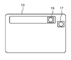
- FIGS. 1A and 1B are views showing an appearance of an information processing apparatus 10 which is an embodiment of an image display apparatus of the present disclosure.
- FIG. 1A is a view of the information processing apparatus 10 viewed from the front
- FIG. 1B is a view of the information processing apparatus 10 viewed from the back.
- the information processing apparatus 10 is a so-called tablet terminal.
- the information processing apparatus 10 has a display unit 13 and a touch panel 15 disposed so as to be superimposed on the display unit 13 on the surface side.
- the information processing apparatus 10 includes a visible light camera 17 and an infrared camera 19 on the back side.
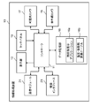
- FIG. 2 is a block diagram showing an internal configuration of the information processing apparatus 10.
- the information processing apparatus 10 includes a controller 11 that controls the entire operation, a display unit 13 that displays various information, a touch panel 15 that a user operates, and a data storage unit 16 that stores data and programs.
- the information processing apparatus 10 further includes a communication module 21 for connecting to a network, and a device interface 23 for connecting an external device.
- the display unit 13 is configured of, for example, a liquid crystal display or an organic EL display.
- the touch panel 15 (an example of the operation unit) is an input device that detects a touch operation by a user's finger or a stylus pen.
- the touch panel 15 is disposed such that the operation area thereof overlaps the display area of the display unit 13.
- the information processing apparatus 10 may further include a button or a slide switch physically provided on the information processing apparatus 10 in addition to the touch panel 15 as an operation member.
- the information processing apparatus 10 can change (reduce / enlarge) the display magnification of the image according to the user operation (pinch in / pinch out operation) on the touch panel 15 and display the image on the display unit 13.
- the communication module 21 is a circuit (module) for connecting to a network, and performs communication in accordance with communication standards such as 3G, 4G, LTE, and WiMAX (registered trademark).
- the device interface 23 is a circuit (module) for connecting to an external device, and performs communication in accordance with a communication standard such as USB (registered trademark), HDMI (registered trademark), Bluetooth (registered trademark) or the like.
- the data storage unit 16 is a recording medium that stores parameters, data, control programs, and the like necessary to realize a predetermined function.
- the data storage unit 16 stores a thermal image display application 16 a (control program) and a temperature / color information conversion table 16 b for realizing the function described later of the information processing apparatus 10.
- the data storage unit 16 is configured by, for example, a hard disk (HDD), a semiconductor storage device (SSD), or a semiconductor memory (RAM).
- the temperature / color information conversion table 16 b is a reference table in which the temperatures of the pixels of the thermal image generated by the infrared camera 19 are associated with the colors of the pixels.
- the visible light camera 17 (an example of a first camera) is an imaging device that has sensitivity in the wavelength region of visible light, detects visible light from a subject, and generates an image (hereinafter referred to as a “visible image”).
- the infrared camera 19 (an example of a second camera) is an imaging device having sensitivity in an infrared wavelength region, and is an imaging device that detects infrared radiation from a subject and generates an image (hereinafter referred to as “infrared image”). .
- the controller 11 includes a CPU, and implements a function of the information processing apparatus 10 described below by executing a control program.
- the controller 11 may be realized only by a hardware circuit designed exclusively for realizing a predetermined function.
- the controller 11 can be configured by various circuits such as an MPU, a GPU, a DSP, an FPGA, and an ASIC, in addition to the CPU.
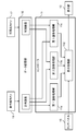
- FIG. 3 is a diagram showing a functional configuration of the controller 11.
- the controller 11 includes a first image processing unit 11a, a second image processing unit 11b, a third image processing unit 11c, and a display processing unit 11d.
- the processing units 11a to 11d are realized by the controller 11 executing the thermal image display application 16a (control program).
- the information processing apparatus 10 has a thermal image display function of displaying a thermal image based on an infrared image captured by the infrared camera 19 on the display unit 13 in various modes.
- the thermal image is an image generated by setting the color of each pixel in accordance with the temperature information of the subject included in the pixel in the infrared image.
- This thermal image display function is realized by the thermal image display application 16a.
- the information processing apparatus 10 has first to third display modes as a display mode of a thermal image in the thermal image display function.
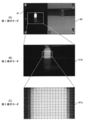
- FIG. 4A shows the first display mode. In the first display mode, a thermal image 41 based on an infrared image captured by the infrared camera 19 and a visible image 40 captured by the visible light camera 17 are displayed side by side.
- FIG. 4B shows the second display mode. The second display mode does not display a visible image, but displays a thermal image 41 b that is larger than the thermal image 41 of the first display mode.
- FIG. 4C shows the third display mode. In the third display mode, a thermal image 41c which is further enlarged than the thermal image 41b in the second display mode is displayed.
- a numerical value (temperature value) indicating the temperature of the area is displayed (see FIG. 5).
- one predetermined area in which the temperature value is indicated corresponds to one pixel of the infrared image (that is, the imaging element of the infrared camera 19). That is, in the third display mode, the temperature value is displayed for each pixel of the infrared image.
- the user can change the magnification (display magnification) of the image displayed on the display unit 13 by performing a gesture operation (pinch in / pinch out) on the image on the touch panel 15.
- the information processing apparatus 10 switches the display mode to any of the first to third display modes according to the display magnification of the thermal image which changes based on the user operation.
- the thermal image 41 when the thermal image 41 is displayed in the first display mode, if the user performs a pinch out (enlargement) operation on the thermal image 41, the thermal image 41 is enlarged and displayed.
- the display mode is switched from the first display mode to the second display mode when the user performs the enlargement operation continuously and the thermal image 41 is enlarged until the visible image 40 disappears.
- the display mode switches from the second display mode to the third display mode Be
- the thermal image 41b is reduced and displayed.
- the display mode changes from the third display mode to the second display mode Can be switched to
- the display mode when the thermal image 41b is further reduced to a size that allows the visible image 40 to be seen, the display mode is switched from the second display mode to the first display mode.
- the display mode of the thermal image can be switched according to the enlargement ratio (display magnification) of the thermal image.
- the image displayed in the first display mode is “first scene image”
- the image displayed in the second display mode is “second scene image”
- the image displayed in the third display mode is “third scene”. It is called an image.
- data of a visible image captured by the visible light camera 17 and data of an infrared image captured by the infrared camera 19 are stored in the data storage unit 16.
- the controller 11 (first to third image processing units 11a to 11c) generates first to third scene images based on the visible image data and the thermal image data stored in the data storage unit 16.
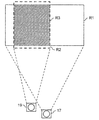
- FIG. 6 is a view for explaining the difference between the imaging ranges (field angles) of the visible light camera 17 and the infrared camera 19 in the information processing apparatus 10.
- the visible light camera 17 has a wider imaging range than the infrared camera 19. It is preferable that the visible image and the thermal image displayed on the display unit 13 have the same angle of view (subject).
- the controller 11 (first image processing unit 11a) is a region R3 (hatched region overlapping with the region R2 of the infrared image generated by the infrared camera 19 from the region R1 of the visible image generated by the visible light camera 17). Trim the part of).
- the controller 11 holds information indicating the positions of the regions R1 to R3 in advance, and can cut out the image of the portion of the region R3 in the region R1 of the visible image based on this information.
- the infrared image generated by the infrared camera 19 includes, for each pixel, information indicating the temperature of the subject in the pixel region.
- the controller 11 generates, from the infrared image generated by the infrared camera 19, a thermal image colored in accordance with the temperature of the pixel for each pixel. Such a thermal image allows the user to intuitively recognize the temperature of the subject. Specifically, the controller 11 determines the color of each pixel based on the temperature information of each pixel of the infrared image with reference to the temperature / color information conversion table 16b, and colors each pixel according to the temperature Generate a thermal image.
- the controller 11 arranges the visible image generated by the trimming and the generated thermal image side by side to generate a first scene image.
- the visible image and the thermal image are the same size.
- the controller 11 superimposes the magnified thermal image on a portion of the visible image to generate a first scene image.
- the controller 11 (second image processing unit 11 b) generates an area R3 overlapping the area R2 of the thermal image by the infrared camera 19 in the area R1 of the visible image by the visible light camera 17 (hatched line Trimming the region)
- the controller 11 extracts an edge (edge) of the trimmed visible image to generate an edge image.
- the controller 11 refers to the temperature / color information conversion table 16 b to generate a thermal image colored based on the temperature so that the user can intuitively recognize the temperature. Then, the controller 11 superimposes the edge image and the thermal image to generate a second scene image.
- the controller 11 (third image processing unit 11c) refers to the temperature / color information conversion table 16b so that the user can visually recognize the temperature visually, and performs coloring based on the temperature To generate a thermal image. Furthermore, the controller 11 generates a third scene image by superimposing a numerical value indicating the temperature of the pixel area for each predetermined pixel area of the thermal image colored based on the temperature.
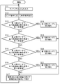
- FIG. 7 is a flowchart showing the switching operation of the thermal image display in the information processing apparatus 10.
- the switching operation of the thermal image display in the information processing apparatus 10 will be described with reference to the flowchart of FIG. 7. This process is mainly executed by the controller 11 (display processing unit 11 d).
- the controller 11 (display processing unit 11 d) inputs information on the user's operation (pinch in / pinch out) on the thermal image from the touch panel 15 (S11).
- the controller 11 sets the display magnification (magnification) of the thermal image in accordance with the user's pinch in operation or pinch out operation (S12).
- the display magnification (magnification) is set based on the size of the infrared image generated by the infrared camera 19.
- the controller 11 switches the display mode based on the display magnification (magnification) set based on the user operation (S13 to S16, S18 to S21). Specifically, the controller 11 switches the display mode as follows.
- the controller 11 switches the display mode from the first display mode to the second display mode (S18). ). Thereby, from the state where the thermal image 41 and the visible image 40 are displayed side by side as shown in FIG. 4 (A), it is switched to the state where the enlarged thermal image 41 b as shown in FIG. 4 (B) is displayed.
- the first predetermined value is set to, for example, the value of the display magnification (magnification ratio) of the thermal image when the visible image 40 is entirely hidden by the magnified thermal image 41 on the display area of the display unit 13 Be done.
- the controller 11 switches the display mode from the second display mode to the first display mode (S19). ).
- the thermal image 41b as shown in FIG. 4B is displayed in the entire display area, and the thermal image 41 and the visible image 40 as shown in FIG. 4A can be displayed. .
- the controller 11 sets the display mode to the second display mode 3 Switch to the display mode (S20).
- the thermal image 41b as shown in FIG. 4B is displayed, and the thermal image 41c as shown in FIG. 4C and FIG. 5 with the superimposed temperature value is displayed.
- Be One temperature value displayed in the third scene image displayed in the third display mode indicates the temperature of the subject corresponding to one pixel of the imaging element of the infrared camera 19.
- the second predetermined value is such that the size of the pixel area of the thermal image corresponding to one pixel of the infrared camera 19 can arrange a numerical value (temperature value) of such a size that the user can visually recognize Set to the display magnification value.
- the thermal image is enlarged by 32 ⁇ 32 times to one pixel of the infrared camera 19
- the second predetermined value is set to 32 ⁇ 32 times.
- the controller 11 switches the display mode from the third display mode to the second display mode. (S21).
- the temperature value as shown in FIG. 4C is not shown and the edge image of the visible image is displayed. It is switched to a state in which the superimposed thermal image 41 b is displayed.
- the controller 11 enlarges or reduces the image at the set display magnification and displays the image (S17).
- the thermal image can be enlarged or reduced according to the touch operation of the user.
- the temperature of the object (heat source) can be confirmed numerically by enlarging the thermal image. That is, the position of the target (heat source) whose temperature is to be checked and its temperature information can be visually recognized in a simple operation including its surroundings, and the user can easily understand the temperature information intuitively.
- the aspect of the display mode is not limited to this. That is, without providing the second display mode, the display mode may be switched between the first display mode and the third display mode.
- the display mode in the third display mode, when the display magnification of the thermal image is not large enough, it is not possible to display a numerical value indicating the temperature of one pixel of the infrared image (image sensor of the infrared camera 19) in a size that allows visual recognition There is a case. Therefore, in the third display mode, when the display magnification of the thermal image is smaller than the predetermined value, the average value of the temperatures of the predetermined number of pixels of the infrared image may be displayed.
- the predetermined number is set to a value such that the size of the region of the predetermined number of pixels can display a numerical value that can be recognized by the user. Thereby, it is possible to display a numerical value indicating the temperature so as to be visible by the user.
- the information processing apparatus 10 (an example of the image display apparatus) according to the present embodiment includes the display unit 13 that displays at least one of the visible image of the subject and the thermal image indicating the temperature information of the subject in color; And a controller 11 (an example of a control unit) that controls the unit 13.
- the controller 11 is a first scene image (an example of a first image) including the thermal image 41 and the visible image 40, and a thermal image which does not include the visible image and is larger than the thermal image of the first scene image
- the display unit 13 is caused to display any one of a third scene image (an example of a second image) including a thermal image 41 c in which a numerical value indicating a temperature is superimposed for each predetermined area.
- the visible image and the thermal image are arranged side by side, so that the position and the shape of the heat source in the thermal image can be accurately grasped by the visible image.
- the temperature information is displayed superimposed on the thermal image (see FIG. 4C and FIG. 5), the user can easily grasp the temperature of the object.
- the user can display necessary images according to the purpose.
- the information processing apparatus 10 further includes a touch panel (an example of an operation unit) for inputting a user operation for enlarging or reducing the thermal image displayed on the display unit 13.
- the controller 11 switches the image to be displayed on the display unit according to the magnification of the thermal image based on the user operation. Thereby, the presentation method of temperature information can be switched by simple operation of expansion / reduction.
- the controller 11 further displays a second scene image including a thermal image 41b which does not include a visible image and is enlarged more than the thermal image 41 of the first scene image and smaller than the thermal image 41c of the third scene image. It can be displayed on 13.
- the controller 11 causes the display unit 13 to display any of the first to third scene images. Thereby, the display mode of the thermal image can be switched in stages according to the magnification of the image.
- the second scene image includes a thermal image on which an edge image extracted from the visible image is superimposed. This makes it easier to recognize the contour of the heat source in the thermal image.
- the thermal image is generated from the infrared image captured by the infrared camera 19.
- the numerical value indicating the temperature in the third scene image indicates the value of the temperature indicated by the temperature information obtained from one pixel of the infrared image. Thereby, the value of the temperature of each area
- the present embodiment also discloses an image display method for displaying on the display unit a thermal image indicating color information of the subject.
- the image display method acquires a visible image of the subject and a thermal image indicating the temperature information of the subject in color, and enlarges or reduces the thermal image by the user to be displayed on the display unit (an example of the display device).
- a second scene image (not including a visible image) but including a thermal image that is enlarged more than the thermal image of the first image and smaller than the thermal image of the second image (third ) May be displayed on the display unit.
- the image displayed on the display unit is switched to any one of the first to third scene images in accordance with the user's operation for enlarging or reducing the thermal image.
- Embodiment 1 has been described as an example of the technology disclosed in the present application.
- the technology in the present disclosure is not limited to this, and is also applicable to embodiments in which changes, replacements, additions, omissions, and the like are appropriately made.
- each component described in the first embodiment can be combined to make a new embodiment. Therefore, other embodiments will be exemplified below.
- the numerical value of the thermal image 41c in the third display mode indicates the temperature of one pixel of the infrared image (image sensor of the infrared camera 19), but the method of displaying the temperature value is limited to this. I will not.
- the numerical value of the thermal image 41c may indicate at least one of an average value, a minimum value, and a maximum value of temperatures in a region formed by a plurality of pixels of the infrared image.
- the display magnification of the image is changed based on the operation on the touch panel 15.
- the operation means for changing the display magnification is not limited to the touch panel. Any input device such as a mouse wheel can be used as a means of changing the display magnification.
- Embodiment 1 has been described by using a tablet terminal as an example of the image display device, the concept of the present disclosure can be applied to other types of electronic devices.
- the idea of the present disclosure can be applied to electronic devices such as smartphones and notebook PCs.
- the thermal image display application 16a and the temperature / color information conversion table 16b may be installed in the information processing apparatus 10 from a portable recording medium such as an optical disk or a memory card, or may be downloaded from a server via a network. Good.
- the second scene image includes an edge image and a thermal image, but the idea of the present disclosure is not limited thereto.
- the second scene image may include a thermal image but not an edge image.
- the processing performed chronologically in the order described is, of course, parallel or individual, not necessarily necessarily chronologically processed. Includes the processing to be performed.
- the image display device of the present disclosure makes it possible to present the user with temperature information of an object in a manner that is intuitively easy to recognize.
- the image display device of the present disclosure is useful for a device that presents temperature information of an object to a user.
Landscapes
- Engineering & Computer Science (AREA)
- Physics & Mathematics (AREA)
- General Physics & Mathematics (AREA)
- Theoretical Computer Science (AREA)
- Human Computer Interaction (AREA)
- Spectroscopy & Molecular Physics (AREA)
- Multimedia (AREA)
- Signal Processing (AREA)
- General Engineering & Computer Science (AREA)
- Computer Vision & Pattern Recognition (AREA)
- Marketing (AREA)
- Business, Economics & Management (AREA)
- Studio Devices (AREA)
- Controls And Circuits For Display Device (AREA)
- Closed-Circuit Television Systems (AREA)
- Radiation Pyrometers (AREA)
Abstract
Provided is an image display device provided with: a display unit displaying at least one of a visible image of a subject and a thermal image showing, in colors, temperature information on the subject; and a control unit controlling the display unit. The control unit makes the display unit display either a first image including a thermal image (41) and a visible image (40) or a second image including no visible image but including a thermal image (41c) which results from enlargement of the thermal image of the first image, and on which numerical values indicating temperatures for respective prescribed areas are superimposed.
Description
本開示は、熱画像を表示可能な画像表示装置に関する。
The present disclosure relates to an image display apparatus capable of displaying a thermal image.
熱画像は、物体から放射される遠赤外線の光を用いて、物体の温度を計測するために使用される画像である。熱画像によって物体の温度がわかるため、異常発熱を起こしている箇所の特定やパイプの中に入り込んだ水の位置や壁面内の空洞位置の特定など欠陥箇所の特定を物体から離れた位置から行うことが可能である。一方、熱画像だけでは実際の位置の特定が困難なため、可視画像と併せて撮影を行い熱画像と可視画像を合わせて表示する方法が考案されている。
A thermal image is an image used to measure the temperature of an object using far-infrared light emitted from the object. Since the temperature of the object can be determined from the thermal image, the defect location is specified from a distance from the object, such as the location of the abnormal heat generation, the location of water in the pipe, and the location of the cavity in the wall. It is possible. On the other hand, since it is difficult to specify the actual position only by the thermal image, a method has been devised in which the visible image is taken together with the thermal image and the visible image is displayed together.
特許文献1は赤外線構造物診断方法を開示する。この赤外線構造物診断方法によれば、欠陥部指定画面として、熱画像と可視画像とを並置して示す第1の表示画面と、熱画像と可視画像とを重ね合わせて示す第2の表示画面と、可視画像のみを上記の第1及び第2の表示画面よりも高い解像度で示す第3の表示画面の少なくとも1つ以上が用意され、診断者により選択された表示画面を表示手段に表示する。診断者により自由に選択された画面を表示することにより、使用者にとって使い勝手のよい診断方法を提供している。
Patent Document 1 discloses an infrared structure diagnostic method. According to the infrared structure diagnostic method, the first display screen showing the thermal image and the visible image side by side and the second display screen showing the thermal image and the visible image superimposed on each other as the defective part specification screen And at least one of a third display screen showing only visible images at a higher resolution than the above first and second display screens is prepared, and the display screen selected by the diagnostician is displayed on the display means . By displaying the screen freely selected by the diagnostician, the user-friendly diagnostic method is provided.
離れた位置から異常発熱等を起こしている箇所を特定する場合、発熱箇所を容易に拡大できることが業務効率を上げていく上で重要である。特許文献1では各画像間の遷移は釦の押下によって行うため、直感的に理解し難いという課題があった。また、可視画像は拡大して表示することが可能な一方で、熱画像は拡大して表示できないので、熱源とその周辺の温度分布を理解することは困難であった。
When identifying a location causing abnormal heat generation or the like from a distant position, it is important to be able to easily expand the heat generation location in order to increase the work efficiency. In patent document 1, since the transition between each image is performed by pressing of a button, there existed a subject that it was hard to understand intuitively. In addition, while visible images can be displayed enlarged, thermal images can not be displayed enlarged, so it was difficult to understand the temperature distribution of the heat source and its surroundings.
本開示は、これらの課題を鑑み、ユーザが熱源の温度情報を直感的かつ容易に認識できる画像表示装置を提供する。
In view of these problems, the present disclosure provides an image display device that allows a user to intuitively and easily recognize temperature information of a heat source.
本開示の第1の態様において画像表示装置が提供される。画像表示装置は、被写体の可視画像および被写体の温度情報を色で示す熱画像の少なくとも一方を表示する表示部と、表示部を制御する制御部と、を備える。制御部は、熱画像と可視画像とを含む第1の画像と、可視画像は含まず、第1の画像の熱画像よりも拡大した熱画像であって、所定の領域毎に温度を示す数値が重ねられた熱画像を含む第2の画像と、のいずれかを表示部に表示させる。
An image display apparatus is provided in a first aspect of the present disclosure. The image display apparatus includes a display unit that displays at least one of a visible image of a subject and a thermal image that indicates the temperature information of the subject, and a control unit that controls the display unit. The control unit is a first image including a thermal image and a visible image, and a thermal image which does not include a visible image but is a magnified image of the thermal image of the first image and indicates a temperature for each predetermined area. Is displayed on the display unit.
本開示の第2の態様において、被写体の温度情報を色で示す熱画像を表示装置に表示させる画像表示方法が提供される。その画像表示方法は、被写体の可視画像と、被写体の温度情報を色で示す熱画像とを取得し、表示装置に表示させる画像を、ユーザによる熱画像を拡大または縮小するための操作に応じて、熱画像と可視画像とを含む第1の画像と、可視画像は含まず、第1の画像の熱画像よりも拡大した熱画像であって、所定の領域毎に温度を示す数値が重ねられた熱画像を含む第2の画像とのいずれかに切り替える。
In a second aspect of the present disclosure, an image display method is provided that causes a display device to display a thermal image that indicates the temperature information of a subject in color. The image display method acquires a visible image of the subject and a thermal image indicating the temperature information of the subject in color, and displays the image displayed on the display device according to the user's operation for enlarging or reducing the thermal image. A first image including a thermal image and a visible image, and a thermal image obtained by enlarging the thermal image of the first image without the visible image, wherein a numerical value indicating a temperature for each predetermined region is superimposed Switch to one of the second image including the thermal image.
本開示の画像表示装置によれば、熱源の温度状態を直感的かつ容易に認識できる態様で表示する。これによりユーザは熱源の温度状態を直感的に理解しやすくなる。
According to the image display device of the present disclosure, the temperature state of the heat source is displayed in a manner that can be intuitively and easily recognized. This makes it easy for the user to intuitively understand the temperature condition of the heat source.
以下、適宜図面を参照しながら、実施の形態を詳細に説明する。但し、必要以上に詳細な説明は省略する場合がある。例えば、既によく知られた事項の詳細説明や実質的に同一の構成に対する重複説明を省略する場合がある。これは、以下の説明が不必要に冗長になるのを避け、当業者の理解を容易にするためである。
Hereinafter, embodiments will be described in detail with reference to the drawings as appropriate. However, the detailed description may be omitted if necessary. For example, detailed description of already well-known matters and redundant description of substantially the same configuration may be omitted. This is to avoid unnecessary redundancy in the following description and to facilitate understanding by those skilled in the art.
なお、発明者(ら)は、当業者が本開示を十分に理解するために添付図面および以下の説明を提供するのであって、これらによって特許請求の範囲に記載の主題を限定することを意図するものではない。
The inventor (s) provide the accompanying drawings and the following description so that those skilled in the art can fully understand the present disclosure, and intend to limit the subject matter described in the claims by these. It is not something to do.
(実施の形態1)
[1-1.構成]
図1Aおよび図1Bは、本開示の画像表示装置の一実施の形態である情報処理装置10の外観を示す図である。図1Aは情報処理装置10を表面から見た図であり、図1Bは情報処理装置10を背面から見た図である。情報処理装置10はいわゆるタブレット端末である。情報処理装置10は、その表面側に、表示部13と、表示部13に重畳して配置されたタッチパネル15とを有する。情報処理装置10は、その背面側に、可視光カメラ17と、赤外線カメラ19とを備える。Embodiment 1
[1-1. Constitution]
FIGS. 1A and 1B are views showing an appearance of aninformation processing apparatus 10 which is an embodiment of an image display apparatus of the present disclosure. FIG. 1A is a view of the information processing apparatus 10 viewed from the front, and FIG. 1B is a view of the information processing apparatus 10 viewed from the back. The information processing apparatus 10 is a so-called tablet terminal. The information processing apparatus 10 has a display unit 13 and a touch panel 15 disposed so as to be superimposed on the display unit 13 on the surface side. The information processing apparatus 10 includes a visible light camera 17 and an infrared camera 19 on the back side.
[1-1.構成]
図1Aおよび図1Bは、本開示の画像表示装置の一実施の形態である情報処理装置10の外観を示す図である。図1Aは情報処理装置10を表面から見た図であり、図1Bは情報処理装置10を背面から見た図である。情報処理装置10はいわゆるタブレット端末である。情報処理装置10は、その表面側に、表示部13と、表示部13に重畳して配置されたタッチパネル15とを有する。情報処理装置10は、その背面側に、可視光カメラ17と、赤外線カメラ19とを備える。
[1-1. Constitution]
FIGS. 1A and 1B are views showing an appearance of an
図2は、情報処理装置10の内部構成を示すブロック図である。情報処理装置10は、その全体動作を制御するコントローラ11と、種々の情報を表示する表示部13と、ユーザが操作を行うタッチパネル15と、データやプログラムを記憶するデータ記憶部16とを備える。さらに、情報処理装置10は、ネットワークに接続するための通信モジュール21と、外部機器を接続するための機器インタフェース23とを備える。
FIG. 2 is a block diagram showing an internal configuration of the information processing apparatus 10. As shown in FIG. The information processing apparatus 10 includes a controller 11 that controls the entire operation, a display unit 13 that displays various information, a touch panel 15 that a user operates, and a data storage unit 16 that stores data and programs. The information processing apparatus 10 further includes a communication module 21 for connecting to a network, and a device interface 23 for connecting an external device.
表示部13は例えば、液晶ディスプレイや有機ELディスプレイで構成される。
The display unit 13 is configured of, for example, a liquid crystal display or an organic EL display.
タッチパネル15(操作部の一例)はユーザの指やスタイラスペンによるタッチ操作を検出する入力デバイスである。タッチパネル15は、その操作領域が表示部13の表示領域と重畳するように配置されている。情報処理装置10は、操作部材として、タッチパネル15に加えて、情報処理装置10に物理的に設けられたボタンやスライドスイッチをさらに備えてもよい。情報処理装置10は、タッチパネル15上でのユーザ操作(ピンチイン/ピンチアウト操作)に応じて画像の表示倍率を変化(縮小/拡大)させて表示部13に表示することができる。
The touch panel 15 (an example of the operation unit) is an input device that detects a touch operation by a user's finger or a stylus pen. The touch panel 15 is disposed such that the operation area thereof overlaps the display area of the display unit 13. The information processing apparatus 10 may further include a button or a slide switch physically provided on the information processing apparatus 10 in addition to the touch panel 15 as an operation member. The information processing apparatus 10 can change (reduce / enlarge) the display magnification of the image according to the user operation (pinch in / pinch out operation) on the touch panel 15 and display the image on the display unit 13.
通信モジュール21はネットワークに接続するための回路(モジュール)であり、3G、4G、LTE、WiMAX(登録商標)といった通信規格にしたがい通信を行う。機器インタフェース23は外部機器と接続するための回路(モジュール)であり、USB(登録商標)、HDMI(登録商標)、Bluetooth(登録商標)等の通信規格にしたがい通信を行う。
The communication module 21 is a circuit (module) for connecting to a network, and performs communication in accordance with communication standards such as 3G, 4G, LTE, and WiMAX (registered trademark). The device interface 23 is a circuit (module) for connecting to an external device, and performs communication in accordance with a communication standard such as USB (registered trademark), HDMI (registered trademark), Bluetooth (registered trademark) or the like.
データ記憶部16は所定の機能を実現するために必要なパラメータ、データ及び制御プログラム等を記憶する記録媒体である。データ記憶部16は、情報処理装置10の後述の機能を実現するための、熱画像表示アプリケーション16a(制御プログラム)と、温度・色情報変換テーブル16bとを格納する。データ記憶部16は例えばハードディスク(HDD)や半導体記憶装置(SSD)や半導体メモリ(RAM)で構成される。温度・色情報変換テーブル16bは、赤外線カメラ19により生成された熱画像の画素の温度と、画素の色とを対応付けた参照テーブルである。
The data storage unit 16 is a recording medium that stores parameters, data, control programs, and the like necessary to realize a predetermined function. The data storage unit 16 stores a thermal image display application 16 a (control program) and a temperature / color information conversion table 16 b for realizing the function described later of the information processing apparatus 10. The data storage unit 16 is configured by, for example, a hard disk (HDD), a semiconductor storage device (SSD), or a semiconductor memory (RAM). The temperature / color information conversion table 16 b is a reference table in which the temperatures of the pixels of the thermal image generated by the infrared camera 19 are associated with the colors of the pixels.
可視光カメラ17(第1カメラの一例)は、可視光の波長領域に感度を持ち、被写体からの可視光を検出して画像(以下「可視画像」という)を生成する撮像装置である。赤外線カメラ19(第2カメラの一例)は、赤外線の波長領域に感度を持つ撮像装置であり、被写体からの赤外線を検出して画像(以下「赤外画像」という)を生成する撮像装置である。
The visible light camera 17 (an example of a first camera) is an imaging device that has sensitivity in the wavelength region of visible light, detects visible light from a subject, and generates an image (hereinafter referred to as a “visible image”). The infrared camera 19 (an example of a second camera) is an imaging device having sensitivity in an infrared wavelength region, and is an imaging device that detects infrared radiation from a subject and generates an image (hereinafter referred to as “infrared image”). .
コントローラ11はCPUを含み、制御プログラムを実行することにより以下に説明する情報処理装置10の機能を実現する。なお、コントローラ11は、所定の機能を実現するように専用に設計されたハードウェア回路のみで実現してもよい。コントローラ11は、CPU以外に、MPU、GPU、DSP、FPGA、ASIC等の種々の回路で構成することができる。
The controller 11 includes a CPU, and implements a function of the information processing apparatus 10 described below by executing a control program. The controller 11 may be realized only by a hardware circuit designed exclusively for realizing a predetermined function. The controller 11 can be configured by various circuits such as an MPU, a GPU, a DSP, an FPGA, and an ASIC, in addition to the CPU.
図3は、コントローラ11の機能的な構成を示す図である。コントローラ11は、第1画像処理部11aと、第2画像処理部11bと、第3画像処理部11cと、表示処理部11dとを含む。これらの処理部11a~11dは、コントローラ11が熱画像表示アプリケーション16a(制御プログラム)を実行することにより実現される。
FIG. 3 is a diagram showing a functional configuration of the controller 11. The controller 11 includes a first image processing unit 11a, a second image processing unit 11b, a third image processing unit 11c, and a display processing unit 11d. The processing units 11a to 11d are realized by the controller 11 executing the thermal image display application 16a (control program).
[1-2.動作]
以上のように構成される情報処理装置10の動作を以下に説明する。 [1-2. Operation]
The operation of theinformation processing apparatus 10 configured as described above will be described below.
以上のように構成される情報処理装置10の動作を以下に説明する。 [1-2. Operation]
The operation of the
本実施の形態の情報処理装置10は、赤外線カメラ19で撮影した赤外画像に基づく熱画像を表示部13に種々の態様で表示する熱画像表示機能を有する。ここで、熱画像とは、赤外画像において、各画素の色をその画素に含まれる被写体の温度情報に応じて設定して生成した画像である。この熱画像表示機能は熱画像表示アプリケーション16aにより実現される。
The information processing apparatus 10 according to the present embodiment has a thermal image display function of displaying a thermal image based on an infrared image captured by the infrared camera 19 on the display unit 13 in various modes. Here, the thermal image is an image generated by setting the color of each pixel in accordance with the temperature information of the subject included in the pixel in the infrared image. This thermal image display function is realized by the thermal image display application 16a.
[1-2-1.表示モード]
情報処理装置10は熱画像表示機能における熱画像の表示モードとして第1~第3表示モードを有する。図4(A)は第1表示モードを示した図である。第1表示モードは、赤外線カメラ19で撮像された赤外画像に基づく熱画像41と、可視光カメラ17で撮像された可視画像40とを並べて表示する。図4(B)は第2表示モードを示した図である。第2表示モードは、可視画像は表示しないが、第1表示モードの熱画像41よりも拡大した熱画像41bを表示する。図4(C)は第3表示モードを示した図である。第3表示モードは、第2表示モードの熱画像41bよりもさらに拡大した熱画像41cを表示する。特に、第3表示モードは、熱画像41cの所定領域毎に、その領域の温度を示す数値(温度値)が表示される(図5参照)。熱画像41cにおいて、温度値が示される1つの所定領域は赤外画像(すなわち、赤外線カメラ19の撮像素子)の1つの画素に対応している。すなわち、第3表示モードでは、赤外画像の画素毎に温度値が表示される。 [1-2-1. Display mode]
Theinformation processing apparatus 10 has first to third display modes as a display mode of a thermal image in the thermal image display function. FIG. 4A shows the first display mode. In the first display mode, a thermal image 41 based on an infrared image captured by the infrared camera 19 and a visible image 40 captured by the visible light camera 17 are displayed side by side. FIG. 4B shows the second display mode. The second display mode does not display a visible image, but displays a thermal image 41 b that is larger than the thermal image 41 of the first display mode. FIG. 4C shows the third display mode. In the third display mode, a thermal image 41c which is further enlarged than the thermal image 41b in the second display mode is displayed. In particular, in the third display mode, for each predetermined area of the thermal image 41c, a numerical value (temperature value) indicating the temperature of the area is displayed (see FIG. 5). In the thermal image 41c, one predetermined area in which the temperature value is indicated corresponds to one pixel of the infrared image (that is, the imaging element of the infrared camera 19). That is, in the third display mode, the temperature value is displayed for each pixel of the infrared image.
情報処理装置10は熱画像表示機能における熱画像の表示モードとして第1~第3表示モードを有する。図4(A)は第1表示モードを示した図である。第1表示モードは、赤外線カメラ19で撮像された赤外画像に基づく熱画像41と、可視光カメラ17で撮像された可視画像40とを並べて表示する。図4(B)は第2表示モードを示した図である。第2表示モードは、可視画像は表示しないが、第1表示モードの熱画像41よりも拡大した熱画像41bを表示する。図4(C)は第3表示モードを示した図である。第3表示モードは、第2表示モードの熱画像41bよりもさらに拡大した熱画像41cを表示する。特に、第3表示モードは、熱画像41cの所定領域毎に、その領域の温度を示す数値(温度値)が表示される(図5参照)。熱画像41cにおいて、温度値が示される1つの所定領域は赤外画像(すなわち、赤外線カメラ19の撮像素子)の1つの画素に対応している。すなわち、第3表示モードでは、赤外画像の画素毎に温度値が表示される。 [1-2-1. Display mode]
The
ユーザは、タッチパネル15上で画像に対するジェスチャ操作(ピンチイン/ピンチアウト)を行うことにより、表示部13に表示される画像の倍率(表示倍率)を変更することができる。特に、情報処理装置10は、ユーザ操作に基づき変化する熱画像の表示倍率に応じて表示モードを第1~第3表示モードのいずれかに切り替える。
The user can change the magnification (display magnification) of the image displayed on the display unit 13 by performing a gesture operation (pinch in / pinch out) on the image on the touch panel 15. In particular, the information processing apparatus 10 switches the display mode to any of the first to third display modes according to the display magnification of the thermal image which changes based on the user operation.
例えば、第1表示モードで熱画像41が表示されているときに、ユーザにより熱画像41に対するピンチアウト(拡大)操作がなされると、熱画像41が拡大されて表示される。ユーザにより連続して拡大操作がなされ、やがて可視画像40が見えなくなるまで熱画像41が拡大されたときに、表示モードが第1表示モードから第2表示モードに切り替えられる。
For example, when the thermal image 41 is displayed in the first display mode, if the user performs a pinch out (enlargement) operation on the thermal image 41, the thermal image 41 is enlarged and displayed. The display mode is switched from the first display mode to the second display mode when the user performs the enlargement operation continuously and the thermal image 41 is enlarged until the visible image 40 disappears.
第2表示モードにおいて、さらにユーザにより熱画像41bに対する拡大操作がなされ、やがて熱画像41bの拡大率(または表示倍率)が所定倍率になると、表示モードが第2表示モードから第3表示モードに切り替えられる。
In the second display mode, when the user performs an enlargement operation on the thermal image 41b and the magnification (or display magnification) of the thermal image 41b eventually reaches a predetermined magnification, the display mode switches from the second display mode to the third display mode Be
第3表示モードにおいて、ユーザにより熱画像41bに対するピンチイン(縮小)操作がなされると、熱画像41bが縮小されて表示される。第3表示モードの状態からユーザにより熱画像41cに対するピンチイン(縮小)操作がなされ、熱画像41cの拡大率(または表示倍率)が所定倍率になると、表示モードが第3表示モードから第2表示モードに切り替えられる。
In the third display mode, when the user performs a pinch-in (reduction) operation on the thermal image 41b, the thermal image 41b is reduced and displayed. When the user performs a pinch-in (reduction) operation on the thermal image 41c from the state of the third display mode and the enlargement ratio (or display magnification) of the thermal image 41c becomes a predetermined magnification, the display mode changes from the third display mode to the second display mode Can be switched to
また、第2表示モードにおいて、熱画像41bがさらに縮小され、可視画像40が見える程度の大きさになると、表示モードが第2表示モードから第1表示モードに切り替えられる。
In the second display mode, when the thermal image 41b is further reduced to a size that allows the visible image 40 to be seen, the display mode is switched from the second display mode to the first display mode.
以上のように、熱画像の拡大率(表示倍率)に応じて熱画像の表示モードが切り替えられる。
As described above, the display mode of the thermal image can be switched according to the enlargement ratio (display magnification) of the thermal image.
第1~第3表示モードのそれぞれにおいて表示部13に表示される画像の生成について説明する。以下、第1表示モードにおいて表示される画像を「第1シーン画像」、第2表示モードにおいて表示される画像を「第2シーン画像」、第3表示モードにおいて表示される画像を「第3シーン画像」という。
Generation of an image displayed on the display unit 13 in each of the first to third display modes will be described. Hereinafter, the image displayed in the first display mode is “first scene image”, the image displayed in the second display mode is “second scene image”, and the image displayed in the third display mode is “third scene”. It is called an image.
図3に示すように、可視光カメラ17で撮像された可視画像のデータおよび赤外線カメラ19で撮像された赤外画像のデータはデータ記憶部16に格納される。コントローラ11(第1ないし第3画像処理部11a~11c)は、データ記憶部16に記憶された可視画像データ及び熱画像データに基づいて第1ないし第3シーン画像を生成する。
As shown in FIG. 3, data of a visible image captured by the visible light camera 17 and data of an infrared image captured by the infrared camera 19 are stored in the data storage unit 16. The controller 11 (first to third image processing units 11a to 11c) generates first to third scene images based on the visible image data and the thermal image data stored in the data storage unit 16.
(1)第1シーン画像の生成
図6は、情報処理装置10における可視光カメラ17と赤外線カメラ19の撮像範囲(画角)の違いを説明した図である。同図に示すように、可視光カメラ17は、赤外線カメラ19よりも広い撮像範囲を有する。表示部13に表示させる可視画像と熱画像は同じ画角(被写体)であることが好ましい。このため、コントローラ11(第1画像処理部11a)は、可視光カメラ17により生成された可視画像の領域R1から、赤外線カメラ19により生成された赤外画像の領域R2と重なる領域R3(斜線領域)の部分をトリミングする。コントローラ11は、予め領域R1~R3の位置を示す情報を保持しており、この情報に基づき可視画像の領域R1中の領域R3の部分の画像を切り出すことができる。 (1) Generation of First Scene Image FIG. 6 is a view for explaining the difference between the imaging ranges (field angles) of thevisible light camera 17 and the infrared camera 19 in the information processing apparatus 10. As shown in the figure, the visible light camera 17 has a wider imaging range than the infrared camera 19. It is preferable that the visible image and the thermal image displayed on the display unit 13 have the same angle of view (subject). For this reason, the controller 11 (first image processing unit 11a) is a region R3 (hatched region overlapping with the region R2 of the infrared image generated by the infrared camera 19 from the region R1 of the visible image generated by the visible light camera 17). Trim the part of). The controller 11 holds information indicating the positions of the regions R1 to R3 in advance, and can cut out the image of the portion of the region R3 in the region R1 of the visible image based on this information.
図6は、情報処理装置10における可視光カメラ17と赤外線カメラ19の撮像範囲(画角)の違いを説明した図である。同図に示すように、可視光カメラ17は、赤外線カメラ19よりも広い撮像範囲を有する。表示部13に表示させる可視画像と熱画像は同じ画角(被写体)であることが好ましい。このため、コントローラ11(第1画像処理部11a)は、可視光カメラ17により生成された可視画像の領域R1から、赤外線カメラ19により生成された赤外画像の領域R2と重なる領域R3(斜線領域)の部分をトリミングする。コントローラ11は、予め領域R1~R3の位置を示す情報を保持しており、この情報に基づき可視画像の領域R1中の領域R3の部分の画像を切り出すことができる。 (1) Generation of First Scene Image FIG. 6 is a view for explaining the difference between the imaging ranges (field angles) of the
赤外線カメラ19により生成される赤外画像は、画素毎に、その画素領域の被写体の温度を示す情報を含む。コントローラ11は、赤外線カメラ19により生成される赤外画像から、画素毎にその画素の温度に応じて色付けした熱画像を生成する。このような熱画像により、ユーザは直感的に被写体の温度を認識できる。具体的には、コントローラ11は、温度・色情報変換テーブル16bを参照して、赤外画像の各画素の温度情報に基づき各画素の色を決定して、温度に応じて各画素を色付けした熱画像を生成する。
The infrared image generated by the infrared camera 19 includes, for each pixel, information indicating the temperature of the subject in the pixel region. The controller 11 generates, from the infrared image generated by the infrared camera 19, a thermal image colored in accordance with the temperature of the pixel for each pixel. Such a thermal image allows the user to intuitively recognize the temperature of the subject. Specifically, the controller 11 determines the color of each pixel based on the temperature information of each pixel of the infrared image with reference to the temperature / color information conversion table 16b, and colors each pixel according to the temperature Generate a thermal image.
コントローラ11は、トリミングにより生成された可視画像と、生成した熱画像とを並べて配置して第1シーン画像を生成する。最初に第1シーン画像が生成されるときは、可視画像と熱画像とは同じサイズである。その後、熱画像が拡大された場合、コントローラ11は、拡大した熱画像を可視画像の一部の上に重ねて第1シーン画像を生成する。
The controller 11 arranges the visible image generated by the trimming and the generated thermal image side by side to generate a first scene image. When the first scene image is generated for the first time, the visible image and the thermal image are the same size. Thereafter, when the thermal image is magnified, the controller 11 superimposes the magnified thermal image on a portion of the visible image to generate a first scene image.
(2)第2シーン画像の生成処理
コントローラ11(第2画像処理部11b)は、可視光カメラ17により可視画像の領域R1のうち、赤外線カメラ19による熱画像の領域R2と重なる領域R3(斜線領域)をトリミングして抽出する。コントローラ11は、トリミングされた可視画像の輪郭(エッジ)を抽出してエッジ画像を生成する。さらに、コントローラ11は、ユーザが直感的に温度を認識しやすいように、温度・色情報変換テーブル16bを参照し、温度に基づき色付けされた熱画像を生成する。そして、コントローラ11は、エッジ画像と熱画像とを重畳して第2シーン画像を生成する。 (2) Generation processing of second scene image The controller 11 (secondimage processing unit 11 b) generates an area R3 overlapping the area R2 of the thermal image by the infrared camera 19 in the area R1 of the visible image by the visible light camera 17 (hatched line Trimming the region) The controller 11 extracts an edge (edge) of the trimmed visible image to generate an edge image. Furthermore, the controller 11 refers to the temperature / color information conversion table 16 b to generate a thermal image colored based on the temperature so that the user can intuitively recognize the temperature. Then, the controller 11 superimposes the edge image and the thermal image to generate a second scene image.
コントローラ11(第2画像処理部11b)は、可視光カメラ17により可視画像の領域R1のうち、赤外線カメラ19による熱画像の領域R2と重なる領域R3(斜線領域)をトリミングして抽出する。コントローラ11は、トリミングされた可視画像の輪郭(エッジ)を抽出してエッジ画像を生成する。さらに、コントローラ11は、ユーザが直感的に温度を認識しやすいように、温度・色情報変換テーブル16bを参照し、温度に基づき色付けされた熱画像を生成する。そして、コントローラ11は、エッジ画像と熱画像とを重畳して第2シーン画像を生成する。 (2) Generation processing of second scene image The controller 11 (second
(3)第3シーン画像の生成処理
コントローラ11(第3画像処理部11c)は、ユーザが視覚的に温度を認識しやすいように、温度・色情報変換テーブル16bを参照し、温度に基づき色付けされた熱画像を生成する。さらに、コントローラ11は、温度に基づき色付けされた熱画像の所定の画素領域毎に、その画素領域の温度を示す数値を重畳して第3シーン画像を生成する。 (3) Third Scene Image Generation Processing The controller 11 (thirdimage processing unit 11c) refers to the temperature / color information conversion table 16b so that the user can visually recognize the temperature visually, and performs coloring based on the temperature To generate a thermal image. Furthermore, the controller 11 generates a third scene image by superimposing a numerical value indicating the temperature of the pixel area for each predetermined pixel area of the thermal image colored based on the temperature.
コントローラ11(第3画像処理部11c)は、ユーザが視覚的に温度を認識しやすいように、温度・色情報変換テーブル16bを参照し、温度に基づき色付けされた熱画像を生成する。さらに、コントローラ11は、温度に基づき色付けされた熱画像の所定の画素領域毎に、その画素領域の温度を示す数値を重畳して第3シーン画像を生成する。 (3) Third Scene Image Generation Processing The controller 11 (third
[1-2-2.熱画像表示の切替え]
図7は、情報処理装置10における熱画像表示の切替え動作を示すフローチャートである。以下、図7のフローチャートを参照して情報処理装置10における熱画像表示の切替え動作を説明する。本処理は主としてコントローラ11(表示処理部11d)により実行される。 1-2-2. Switching of thermal image display]
FIG. 7 is a flowchart showing the switching operation of the thermal image display in theinformation processing apparatus 10. Hereinafter, the switching operation of the thermal image display in the information processing apparatus 10 will be described with reference to the flowchart of FIG. 7. This process is mainly executed by the controller 11 (display processing unit 11 d).
図7は、情報処理装置10における熱画像表示の切替え動作を示すフローチャートである。以下、図7のフローチャートを参照して情報処理装置10における熱画像表示の切替え動作を説明する。本処理は主としてコントローラ11(表示処理部11d)により実行される。 1-2-2. Switching of thermal image display]
FIG. 7 is a flowchart showing the switching operation of the thermal image display in the
コントローラ11(表示処理部11d)は、タッチパネル15から、熱画像に対するユーザ操作(ピンチイン/ピンチアウト)に関する情報を入力する(S11)。コントローラ11は、ユーザのピンチイン操作またはピンチアウト操作に応じて熱画像の表示倍率(拡大率)を設定する(S12)。表示倍率(拡大率)は、赤外線カメラ19により生成された赤外画像のサイズを基準に設定される。
The controller 11 (display processing unit 11 d) inputs information on the user's operation (pinch in / pinch out) on the thermal image from the touch panel 15 (S11). The controller 11 sets the display magnification (magnification) of the thermal image in accordance with the user's pinch in operation or pinch out operation (S12). The display magnification (magnification) is set based on the size of the infrared image generated by the infrared camera 19.
その後、コントローラ11は、ユーザ操作に基づき設定された表示倍率(拡大率)に基づき表示モードの切替えを行う(S13~S16、S18~S21)。具体的にはコントローラ11は以下のように表示モードの切替えを行う。
Thereafter, the controller 11 switches the display mode based on the display magnification (magnification) set based on the user operation (S13 to S16, S18 to S21). Specifically, the controller 11 switches the display mode as follows.
第1表示モードにおいて、設定された熱画像の表示倍率が第1所定値よりも大きいときは(S13でYES)、コントローラ11は、表示モードを第1表示モードから第2表示モードに切り替える(S18)。これにより、図4(A)に示すような熱画像41と可視画像40が並べて表示される状態から、図4(B)に示すような拡大された熱画像41bが表示される状態に切り替えられる。ここで、第1所定値は、例えば、表示部13の表示領域上で、拡大された熱画像41により可視画像40が全て隠れてしまうときの熱画像の表示倍率(拡大率)の値に設定される。
In the first display mode, when the set display magnification of the thermal image is larger than the first predetermined value (YES in S13), the controller 11 switches the display mode from the first display mode to the second display mode (S18). ). Thereby, from the state where the thermal image 41 and the visible image 40 are displayed side by side as shown in FIG. 4 (A), it is switched to the state where the enlarged thermal image 41 b as shown in FIG. 4 (B) is displayed. . Here, the first predetermined value is set to, for example, the value of the display magnification (magnification ratio) of the thermal image when the visible image 40 is entirely hidden by the magnified thermal image 41 on the display area of the display unit 13 Be done.
第2表示モードにおいて、設定された熱画像の表示倍率が第1所定値よりも小さいときは(S14でYES)、コントローラ11は、表示モードを第2表示モードから第1表示モードに切り替える(S19)。これにより、図4(B)に示すような熱画像41bが表示領域全体に表示される状態から、図4(A)に示すような熱画像41と可視画像40が表示される状態に切り替えられる。
In the second display mode, when the set display magnification of the thermal image is smaller than the first predetermined value (YES in S14), the controller 11 switches the display mode from the second display mode to the first display mode (S19). ). Thus, the thermal image 41b as shown in FIG. 4B is displayed in the entire display area, and the thermal image 41 and the visible image 40 as shown in FIG. 4A can be displayed. .
第2表示モードにおいて、設定された熱画像の表示倍率が第2所定値(>第1所定値)よりも大きいときは(S15でYES)、コントローラ11は、表示モードを第2表示モードから第3表示モードに切り替える(S20)。これにより、図4(B)に示すような熱画像41bが表示される状態から、図4(C)及び図5に示すような温度値が重畳された熱画像41cが表示される状態に切り替えられる。第3表示モードで表示される第3シーン画像で表示される1つの温度値は、赤外線カメラ19の撮像素子の1画素に対応する被写体の温度を示す。よって第3シーン画像において、赤外線カメラ19の1画素に対応する画素領域のサイズが小さいと、ユーザが温度値を視認する程度の数値をその画素領域に重ねて表示することができない。よって、第2所定値は、赤外線カメラ19の1画素に対応する熱画像の画素領域の大きさが、ユーザが視認できる程度の大きさの数値(温度値)を配置できるような大きさになる表示倍率の値に設定される。例えば、ユーザが視認できる程度の画素領域の大きさとして、縦32画素×横32画素の領域が必要な場合、熱画像は32×32倍に拡大されたときに、赤外線カメラ19の1画素に対応する熱画像の画素領域において、ユーザが視認できる程度の大きさの数値(温度値)を配置できる。よって、この場合、第2所定値は32×32倍に設定される。
In the second display mode, when the set display magnification of the thermal image is larger than the second predetermined value (> first predetermined value) (YES in S15), the controller 11 sets the display mode to the second display mode 3 Switch to the display mode (S20). Thus, the thermal image 41b as shown in FIG. 4B is displayed, and the thermal image 41c as shown in FIG. 4C and FIG. 5 with the superimposed temperature value is displayed. Be One temperature value displayed in the third scene image displayed in the third display mode indicates the temperature of the subject corresponding to one pixel of the imaging element of the infrared camera 19. Therefore, in the third scene image, when the size of the pixel area corresponding to one pixel of the infrared camera 19 is small, it is not possible to superimpose and display a numerical value that allows the user to visually recognize the temperature value. Therefore, the second predetermined value is such that the size of the pixel area of the thermal image corresponding to one pixel of the infrared camera 19 can arrange a numerical value (temperature value) of such a size that the user can visually recognize Set to the display magnification value. For example, when the area of 32 vertical pixels × 32 horizontal pixels is required as the size of the pixel area visible to the user, the thermal image is enlarged by 32 × 32 times to one pixel of the infrared camera 19 In the pixel area of the corresponding thermal image, it is possible to arrange a numerical value (temperature value) of a size that can be visually recognized by the user. Therefore, in this case, the second predetermined value is set to 32 × 32 times.
また、第3表示モードにおいて、設定された熱画像の表示倍率が第2所定値よりも小さいときは(S16でYES)、コントローラ11は、表示モードを第3表示モードから第2表示モードに切り替える(S21)。これにより、図4(C)に示すような温度値が重畳された熱画像41cが表示される状態から、図4(B)に示すような、温度値は示されず、可視画像のエッジ画像が重畳された熱画像41bが表示される状態に切り替えられる。
In the third display mode, when the set display magnification of the thermal image is smaller than the second predetermined value (YES in S16), the controller 11 switches the display mode from the third display mode to the second display mode. (S21). Thus, from the state where the thermal image 41c on which the temperature value is superimposed as shown in FIG. 4C is displayed, the temperature value as shown in FIG. 4B is not shown and the edge image of the visible image is displayed. It is switched to a state in which the superimposed thermal image 41 b is displayed.
その後、コントローラ11は、設定した表示倍率で画像を拡大または縮小して表示させる(S17)。
Thereafter, the controller 11 enlarges or reduces the image at the set display magnification and displays the image (S17).
以上のように、本実施の形態の情報処理装置10によれば、ユーザのタッチ操作に応じて熱画像を拡大、縮小できる。また、熱画像を拡大させることにより、対象物(熱源)の温度を数値で確認することができる。すなわち、温度を確認したい対象物(熱源)の位置とその温度情報をその周辺も含めて単純な動作で視覚的に認識することができ、ユーザは温度情報を直感的に理解しやすくなる。
As described above, according to the information processing apparatus 10 of the present embodiment, the thermal image can be enlarged or reduced according to the touch operation of the user. In addition, the temperature of the object (heat source) can be confirmed numerically by enlarging the thermal image. That is, the position of the target (heat source) whose temperature is to be checked and its temperature information can be visually recognized in a simple operation including its surroundings, and the user can easily understand the temperature information intuitively.
なお、上記の例では、3つの表示モードを設定したが、表示モードの態様はこれに限定されない。すなわち、第2表示モードを設けずに、第1表示モードと第3表示モードの間で切り替えるようにしてもよい。この場合、第3表示モードにおいて、熱画像の表示倍率が十分に大きくない場合、赤外画像(赤外線カメラ19の撮像素子)の1画素の温度を示す数値を視認できる程の大きさに表示できない場合がある。よって、第3表示モードにおいて、熱画像の表示倍率が所定値よりも小さい場合に、赤外画像の所定数の画素の温度の平均値を表示するようにすればよい。ここで、所定数は、所定数の画素の領域の大きさが、ユーザが認識できる程度の数値を表示できる大きさとなるような値に設定する。これにより、ユーザにより視認できるように温度を示す数値を表示することができる。
Although three display modes are set in the above example, the aspect of the display mode is not limited to this. That is, without providing the second display mode, the display mode may be switched between the first display mode and the third display mode. In this case, in the third display mode, when the display magnification of the thermal image is not large enough, it is not possible to display a numerical value indicating the temperature of one pixel of the infrared image (image sensor of the infrared camera 19) in a size that allows visual recognition There is a case. Therefore, in the third display mode, when the display magnification of the thermal image is smaller than the predetermined value, the average value of the temperatures of the predetermined number of pixels of the infrared image may be displayed. Here, the predetermined number is set to a value such that the size of the region of the predetermined number of pixels can display a numerical value that can be recognized by the user. Thereby, it is possible to display a numerical value indicating the temperature so as to be visible by the user.
[1-3.効果等]
以上のように、本実施の形態の情報処理装置10(画像表示装置の一例)は、被写体の可視画像および被写体の温度情報を色で示す熱画像の少なくとも一方を表示する表示部13と、表示部13を制御するコントローラ11(制御部の一例)と、を備える。コントローラ11は、熱画像41と可視画像40とを含む第1シーン画像(第1の画像の一例)と、可視画像は含まず、第1シーン画像の熱画像よりも拡大した熱画像であって、所定の領域毎に温度を示す数値が重ねられた熱画像41cを含む第3シーン画像(第2の画像の一例)とのいずれかを表示部13に表示させる。 [1-3. Effect etc]
As described above, the information processing apparatus 10 (an example of the image display apparatus) according to the present embodiment includes thedisplay unit 13 that displays at least one of the visible image of the subject and the thermal image indicating the temperature information of the subject in color; And a controller 11 (an example of a control unit) that controls the unit 13. The controller 11 is a first scene image (an example of a first image) including the thermal image 41 and the visible image 40, and a thermal image which does not include the visible image and is larger than the thermal image of the first scene image The display unit 13 is caused to display any one of a third scene image (an example of a second image) including a thermal image 41 c in which a numerical value indicating a temperature is superimposed for each predetermined area.
以上のように、本実施の形態の情報処理装置10(画像表示装置の一例)は、被写体の可視画像および被写体の温度情報を色で示す熱画像の少なくとも一方を表示する表示部13と、表示部13を制御するコントローラ11(制御部の一例)と、を備える。コントローラ11は、熱画像41と可視画像40とを含む第1シーン画像(第1の画像の一例)と、可視画像は含まず、第1シーン画像の熱画像よりも拡大した熱画像であって、所定の領域毎に温度を示す数値が重ねられた熱画像41cを含む第3シーン画像(第2の画像の一例)とのいずれかを表示部13に表示させる。 [1-3. Effect etc]
As described above, the information processing apparatus 10 (an example of the image display apparatus) according to the present embodiment includes the
上記構成により、第1シーン画像では、可視画像と熱画像が並べて配置されることから、熱画像における熱源の位置や形状を可視画像により正確に把握することができる。また、第3シーン画像では、熱画像に重畳して温度情報を表示するため(図4(C),図5参照)、ユーザは対象物の温度を容易に把握することができる。このようにユーザは目的に応じて必要な画像を表示させることができる。
With the above configuration, in the first scene image, the visible image and the thermal image are arranged side by side, so that the position and the shape of the heat source in the thermal image can be accurately grasped by the visible image. Further, in the third scene image, since the temperature information is displayed superimposed on the thermal image (see FIG. 4C and FIG. 5), the user can easily grasp the temperature of the object. Thus, the user can display necessary images according to the purpose.
情報処理装置10は、表示部13に表示される熱画像を拡大または縮小するためのユーザ操作を入力するタッチパネル(操作部の一例)をさらに備える。コントローラ11は、ユーザ操作に基づく熱画像の拡大率に応じて表示部に表示させる画像を切り替える。これにより、拡大/縮小という簡単な操作により温度情報の提示方法を切り替えることができる。
The information processing apparatus 10 further includes a touch panel (an example of an operation unit) for inputting a user operation for enlarging or reducing the thermal image displayed on the display unit 13. The controller 11 switches the image to be displayed on the display unit according to the magnification of the thermal image based on the user operation. Thereby, the presentation method of temperature information can be switched by simple operation of expansion / reduction.
コントローラ11は、さらに、可視画像は含まず、第1シーン画像の熱画像41よりも拡大され且つ第3シーン画像の熱画像41cよりも縮小された熱画像41bを含む第2シーン画像を表示部13に表示可能である。コントローラ11は、第1ないし第3シーン画像のいずれかを表示部13に表示させる。これにより、画像の拡大率に応じて熱画像の表示態様を段階的に切り替えることができる。
The controller 11 further displays a second scene image including a thermal image 41b which does not include a visible image and is enlarged more than the thermal image 41 of the first scene image and smaller than the thermal image 41c of the third scene image. It can be displayed on 13. The controller 11 causes the display unit 13 to display any of the first to third scene images. Thereby, the display mode of the thermal image can be switched in stages according to the magnification of the image.
第2シーン画像は、可視画像から抽出したエッジ画像が重畳された熱画像を含む。これにより熱画像において熱源の輪郭をより認識し易くなる。
The second scene image includes a thermal image on which an edge image extracted from the visible image is superimposed. This makes it easier to recognize the contour of the heat source in the thermal image.
熱画像は赤外線カメラ19により撮像された赤外画像から生成される。第3シーン画像における温度を示す数値は、赤外画像の1画素から得られる温度情報が示す温度の値を示す。これにより、熱源の各領域の温度の値を把握することができる。
The thermal image is generated from the infrared image captured by the infrared camera 19. The numerical value indicating the temperature in the third scene image indicates the value of the temperature indicated by the temperature information obtained from one pixel of the infrared image. Thereby, the value of the temperature of each area | region of a heat source can be grasped | ascertained.
また、本実施の形態は、被写体の温度情報を色で示す熱画像を表示部に表示させる画像表示方法も開示する。
In addition, the present embodiment also discloses an image display method for displaying on the display unit a thermal image indicating color information of the subject.
その画像表示方法は、被写体の可視画像と、被写体の温度情報を色で示す熱画像とを取得し、表示部(表示装置の一例)に表示させる画像を、ユーザによる熱画像を拡大または縮小するための操作に応じて、熱画像と可視画像とを含む第1シーン画像(第1の画像)と、可視画像は含まず、第1の画像の熱画像よりも拡大した熱画像であって、所定の領域毎に温度を示す数値が重ねられた熱画像を含む第3シーン画像(第2の画像)とのいずれかに切り替える。
The image display method acquires a visible image of the subject and a thermal image indicating the temperature information of the subject in color, and enlarges or reduces the thermal image by the user to be displayed on the display unit (an example of the display device). A first scene image (first image) including a thermal image and a visible image, and a thermal image which is larger than the thermal image of the first image, not including the visible image, according to the operation for It switches to any of the 3rd scene image (2nd image) containing the thermal image on which the numerical value which shows temperature for every predetermined area | region was superimposed.
上記の画像表示方法において、さらに、可視画像は含まず、第1の画像の熱画像よりも拡大され且つ第2の画像の熱画像よりも縮小された熱画像を含む第2シーン画像(第3の画像)を表示部に表示させてもよい。このとき、表示部に表示させる画像を、ユーザによる熱画像を拡大または縮小するための操作に応じて、第1ないし第3シーン画像のうちのいずれかに切り替える。
In the above-described image display method, a second scene image (not including a visible image) but including a thermal image that is enlarged more than the thermal image of the first image and smaller than the thermal image of the second image (third ) May be displayed on the display unit. At this time, the image displayed on the display unit is switched to any one of the first to third scene images in accordance with the user's operation for enlarging or reducing the thermal image.
(他の実施の形態)
以上のように、本出願において開示する技術の例示として、実施の形態1を説明した。しかしながら、本開示における技術は、これに限定されず、適宜、変更、置き換え、付加、省略などを行った実施の形態にも適用可能である。また、上記実施の形態1で説明した各構成要素を組み合わせて、新たな実施の形態とすることも可能である。そこで、以下、他の実施の形態を例示する。 (Other embodiments)
As described above,Embodiment 1 has been described as an example of the technology disclosed in the present application. However, the technology in the present disclosure is not limited to this, and is also applicable to embodiments in which changes, replacements, additions, omissions, and the like are appropriately made. Further, each component described in the first embodiment can be combined to make a new embodiment. Therefore, other embodiments will be exemplified below.
以上のように、本出願において開示する技術の例示として、実施の形態1を説明した。しかしながら、本開示における技術は、これに限定されず、適宜、変更、置き換え、付加、省略などを行った実施の形態にも適用可能である。また、上記実施の形態1で説明した各構成要素を組み合わせて、新たな実施の形態とすることも可能である。そこで、以下、他の実施の形態を例示する。 (Other embodiments)
As described above,
実施の形態1では、第3表示モードにおいて熱画像41cの数値は、赤外画像(赤外線カメラ19の撮像素子)の1画素の温度を示していたが、温度値の表示の方法はこれに限定されない。熱画像41cの数値は、赤外画像の複数画素で構成される領域内の温度の平均値、最小値および最大値の少なくとも一つを示してもよい。
In the first embodiment, the numerical value of the thermal image 41c in the third display mode indicates the temperature of one pixel of the infrared image (image sensor of the infrared camera 19), but the method of displaying the temperature value is limited to this. I will not. The numerical value of the thermal image 41c may indicate at least one of an average value, a minimum value, and a maximum value of temperatures in a region formed by a plurality of pixels of the infrared image.
実施の形態1においては、タッチパネル15上の操作に基づき画像の表示倍率の変更を行ったが、表示倍率の変更のための操作手段はタッチパネルに限定されない。マウスホイールのような任意の入力デバイスを表示倍率の変更の手段として利用できる。
In the first embodiment, the display magnification of the image is changed based on the operation on the touch panel 15. However, the operation means for changing the display magnification is not limited to the touch panel. Any input device such as a mouse wheel can be used as a means of changing the display magnification.
実施の形態1では、画像表示装置としてタブレット端末を例として用いて説明したが、本開示の思想は他の種類の電子機器に対しても適用できる。例えば、本開示の思想は、スマートフォン、ノート型PCのような電子機器にも適用できる。
Although Embodiment 1 has been described by using a tablet terminal as an example of the image display device, the concept of the present disclosure can be applied to other types of electronic devices. For example, the idea of the present disclosure can be applied to electronic devices such as smartphones and notebook PCs.
熱画像表示アプリケーション16aおよび温度・色情報変換テーブル16bは、光ディスクやメモリカードのような可搬性の記録媒体から情報処理装置10にインストールしてもよいし、ネットワークを介してサーバからダウンロードしてもよい。
The thermal image display application 16a and the temperature / color information conversion table 16b may be installed in the information processing apparatus 10 from a portable recording medium such as an optical disk or a memory card, or may be downloaded from a server via a network. Good.
実施の形態1では、第2シーン画像は、エッジ画像と熱画像とを含むが、本開示の思想はこれに限らない。第2シーン画像は、熱画像を含むがエッジ画像を含まないこととしてもよい。
In the first embodiment, the second scene image includes an edge image and a thermal image, but the idea of the present disclosure is not limited thereto. The second scene image may include a thermal image but not an edge image.
以上のように、本開示における技術の例示として、実施の形態を説明した。そのために、添付図面および詳細な説明を提供した。
As described above, the embodiment has been described as an example of the technology in the present disclosure. For that purpose, the attached drawings and the detailed description are provided.
したがって、添付図面および詳細な説明に記載された構成要素の中には、課題解決のために必須な構成要素だけでなく、上記技術を例示するために、課題解決のためには必須でない構成要素も含まれ得る。そのため、それらの必須ではない構成要素が添付図面や詳細な説明に記載されていることをもって、直ちに、それらの必須ではない構成要素が必須であるとの認定をするべきではない。
Therefore, among the components described in the attached drawings and the detailed description, not only components essential for solving the problem but also components not essential for solving the problem in order to exemplify the above-mentioned technology May also be included. Therefore, the fact that those non-essential components are described in the attached drawings and the detailed description should not immediately mean that those non-essential components are essential.
本明細書において、記録媒体に記録されるプログラムを記述するステップは、記載された順序に沿って時系列的に行われる処理は、もちろん、必ずしも時系列的に処理されなくとも、並列的あるいは個別に実行される処理を含むものである。
In the present specification, in the step of describing the program recorded on the recording medium, the processing performed chronologically in the order described is, of course, parallel or individual, not necessarily necessarily chronologically processed. Includes the processing to be performed.
また、上述の実施の形態は、本開示における技術を例示するためのものであるから、特許請求の範囲またはその均等の範囲において種々の変更、置き換え、付加、省略などを行うことができる。
In addition, since the above-described embodiment is for illustrating the technique in the present disclosure, various modifications, replacements, additions, omissions, and the like can be made within the scope of the claims or the equivalents thereof.
本開示の画像表示装置は、対象物の温度情報を直感的に認識しやすい方法でユーザに提示することを可能とする。よって、本開示の画像表示装置は、対象物の温度情報をユーザに提示する装置に有用である。
The image display device of the present disclosure makes it possible to present the user with temperature information of an object in a manner that is intuitively easy to recognize. Thus, the image display device of the present disclosure is useful for a device that presents temperature information of an object to a user.
10 情報処理装置
11 コントローラ
13 表示部
16 データ記憶部
16a 熱画像表示アプリケーション
16b 温度・色情報変換テーブル
17 可視光カメラ
19 赤外線カメラ DESCRIPTION OFSYMBOLS 10 information processing apparatus 11 controller 13 display part 16 data storage part 16a thermal image display application 16b temperature and color information conversion table 17 visible light camera 19 infrared camera
11 コントローラ
13 表示部
16 データ記憶部
16a 熱画像表示アプリケーション
16b 温度・色情報変換テーブル
17 可視光カメラ
19 赤外線カメラ DESCRIPTION OF
Claims (11)
- 被写体の可視画像および被写体の温度情報を色で示す熱画像の少なくとも一方を表示する表示部と、
前記表示部を制御する制御部と、を備え、
前記制御部は、
前記熱画像と前記可視画像とを含む第1の画像と、
前記可視画像は含まず、前記第1の画像の熱画像よりも拡大した熱画像であって、所定の領域毎に温度を示す数値が重ねられた熱画像を含む第2の画像とのいずれかを前記表示部に表示させる、画像表示装置。 A display unit for displaying at least one of a visible image of the subject and a thermal image showing color information of the subject;
A control unit that controls the display unit;
The control unit
A first image comprising the thermal image and the visible image;
The thermal image expanded from the thermal image of the first image, which does not include the visible image, and is any one of a second image including a thermal image in which a numerical value indicating a temperature is superimposed for each predetermined region. An image display apparatus for displaying on the display unit. - 前記表示部に表示される熱画像を拡大または縮小するためのユーザ操作を入力する操作部をさらに備え、
前記制御部は、前記ユーザ操作に基づく前記熱画像の拡大率に応じて前記表示部に表示させる画像を前記第1の画像と前記第2の画像とのいずれかに切り替える、請求項1記載の画像表示装置。 It further comprises an operation unit for inputting a user operation for enlarging or reducing the thermal image displayed on the display unit,
The controller according to claim 1, wherein the control unit switches an image to be displayed on the display unit to any one of the first image and the second image according to a magnification of the thermal image based on the user operation. Image display device. - 前記制御部は、
さらに、前記可視画像は含まず、前記第1の画像の熱画像よりも拡大され且つ前記第2の画像の熱画像よりも縮小された熱画像を含む第3の画像を前記表示部に表示可能であり、
前記第1ないし第3の画像のいずれかを前記表示部に表示させる、
請求項1記載の画像表示装置。 The control unit
Furthermore, it is possible to display on the display unit a third image that does not include the visible image, and that includes a thermal image that is larger than the thermal image of the first image and smaller than the thermal image of the second image. And
Displaying any one of the first to third images on the display unit;
The image display apparatus according to claim 1. - 前記第3の画像は、前記可視画像から抽出したエッジ画像が重畳された熱画像を含む、請求項3記載の画像表示装置。 The image display device according to claim 3, wherein the third image includes a thermal image on which an edge image extracted from the visible image is superimposed.
- 前記熱画像は赤外線カメラにより撮像された赤外画像から生成され、
前記第2の画像における温度を示す数値は、前記赤外画像の1画素から得られる温度情報の値を示す、請求項1記載の画像表示装置。 The thermal image is generated from an infrared image captured by an infrared camera,
The image display device according to claim 1, wherein the numerical value indicating the temperature in the second image indicates a value of temperature information obtained from one pixel of the infrared image. - 前記熱画像は赤外線カメラにより撮像された赤外画像から生成され、
前記第2の画像における温度を示す数値は、前記赤外画像の所定数の画素から得られる温度情報の値の平均値を示す、請求項1記載の画像表示装置。 The thermal image is generated from an infrared image captured by an infrared camera,
The image display apparatus according to claim 1, wherein the numerical value indicating the temperature in the second image indicates an average value of temperature information obtained from a predetermined number of pixels of the infrared image. - 前記可視画像を撮影可能な第1カメラと、赤外画像を撮影可能な第2カメラと、をさらに備え、
前記制御部は、前記赤外画像に基づき前記熱画像を生成する、請求項1記載の画像表示装置。 It further comprises a first camera capable of capturing the visible image, and a second camera capable of capturing an infrared image,
The image display apparatus according to claim 1, wherein the control unit generates the thermal image based on the infrared image. - タブレット端末である、請求項1記載の画像表示装置。 The image display device according to claim 1, which is a tablet terminal.
- 被写体の温度情報を色で示す熱画像を表示装置に表示させる画像表示方法であって、
前記被写体の可視画像と、前記被写体の温度情報を色で示す熱画像とを取得し、
前記表示装置に表示させる画像を、ユーザによる前記熱画像を拡大または縮小するための操作に応じて、
前記熱画像と前記可視画像とを含む第1の画像と、
前記可視画像は含まず、前記第1の画像の前記熱画像よりも拡大した熱画像であって、所定の領域毎に温度を示す数値が重ねられた熱画像を含む第2の画像とのいずれかに切り替える、画像表示方法。 An image display method for displaying on a display device a thermal image showing color information of temperature of an object.
Acquiring a visible image of the subject and a thermal image showing color information of the subject in color;
According to an operation by the user for enlarging or reducing the thermal image, the image to be displayed on the display device
A first image comprising the thermal image and the visible image;
Any of a thermal image which does not include the visible image and which is a thermal image expanded from the thermal image of the first image and which includes a thermal image in which a numerical value indicating a temperature is superimposed for each predetermined area How to switch to an image display method. - さらに、前記可視画像は含まず、前記第1の画像の前記熱画像よりも拡大され且つ前記第2の画像の前記熱画像よりも縮小された熱画像を含む第3の画像を前記表示装置に表示させ、
前記表示装置に表示させる画像を、前記ユーザによる前記熱画像を拡大または縮小するための前記操作に応じて、前記第1ないし第3の画像のうちのいずれかに切り替える、請求項9記載の画像表示方法。 Furthermore, on the display device, a third image that does not include the visible image but includes a thermal image that is larger than the thermal image of the first image and smaller than the thermal image of the second image Display
10. The image according to claim 9, wherein the image to be displayed on the display device is switched to any one of the first to third images in response to the user's operation for enlarging or reducing the thermal image. Display method. - 請求項9または10記載の画像表示方法を情報処理装置に実行させるためのプログラム。 A program for causing an information processing apparatus to execute the image display method according to claim 9 or 10.
Priority Applications (4)
| Application Number | Priority Date | Filing Date | Title |
|---|---|---|---|
| EP18758368.7A EP3588943B1 (en) | 2017-02-23 | 2018-02-14 | Image display device, image display method, and program |
| CN201880013107.6A CN110326292B (en) | 2017-02-23 | 2018-02-14 | Image display device, image display method, and storage medium |
| JP2019501242A JP7042398B2 (en) | 2017-02-23 | 2018-02-14 | Image display device, image display method, and program |
| US16/541,318 US11037334B2 (en) | 2017-02-23 | 2019-08-15 | Image display device, image display method, and program |
Applications Claiming Priority (2)
| Application Number | Priority Date | Filing Date | Title |
|---|---|---|---|
| JP2017032525 | 2017-02-23 | ||
| JP2017-032525 | 2017-02-23 |
Related Child Applications (1)
| Application Number | Title | Priority Date | Filing Date |
|---|---|---|---|
| US16/541,318 Continuation US11037334B2 (en) | 2017-02-23 | 2019-08-15 | Image display device, image display method, and program |
Publications (1)
| Publication Number | Publication Date |
|---|---|
| WO2018155267A1 true WO2018155267A1 (en) | 2018-08-30 |
Family
ID=63252619
Family Applications (1)
| Application Number | Title | Priority Date | Filing Date |
|---|---|---|---|
| PCT/JP2018/004962 WO2018155267A1 (en) | 2017-02-23 | 2018-02-14 | Image display device, image display method, and program |
Country Status (5)
| Country | Link |
|---|---|
| US (1) | US11037334B2 (en) |
| EP (1) | EP3588943B1 (en) |
| JP (1) | JP7042398B2 (en) |
| CN (1) | CN110326292B (en) |
| WO (1) | WO2018155267A1 (en) |
Cited By (2)
| Publication number | Priority date | Publication date | Assignee | Title |
|---|---|---|---|---|
| WO2020085303A1 (en) * | 2018-10-22 | 2020-04-30 | パナソニックIpマネジメント株式会社 | Information processing device and information processing method |
| WO2022091702A1 (en) * | 2020-10-30 | 2022-05-05 | 富士フイルム株式会社 | Infrared thermal image analysis device, infrared thermal image analysis method, and program |
Families Citing this family (3)
| Publication number | Priority date | Publication date | Assignee | Title |
|---|---|---|---|---|
| JP6915629B2 (en) * | 2016-12-27 | 2021-08-04 | ソニーグループ株式会社 | Product design system and design image correction device |
| JP7367597B2 (en) * | 2020-04-17 | 2023-10-24 | 新東工業株式会社 | Image display device, image display method and control program |
| JP7517114B2 (en) | 2020-11-30 | 2024-07-17 | 新東工業株式会社 | Image display device |
Citations (5)
| Publication number | Priority date | Publication date | Assignee | Title |
|---|---|---|---|---|
| WO2002023142A1 (en) * | 2000-09-04 | 2002-03-21 | Noboru Hayakawa | Temperature indicator and temperature monitor system |
| JP2005016991A (en) * | 2003-06-24 | 2005-01-20 | Railway Technical Res Inst | Infrared structure diagnosis system |
| JP2005016995A (en) | 2003-06-24 | 2005-01-20 | Railway Technical Res Inst | Infrared structure diagnosis method |
| JP2010194073A (en) * | 2009-02-25 | 2010-09-09 | Terumo Corp | Infrared thermography device |
| JP2015194367A (en) * | 2014-03-31 | 2015-11-05 | 株式会社電子技術工房 | Temperature measurement device, display processing program of measurement result and temperature measurement system |
Family Cites Families (16)
| Publication number | Priority date | Publication date | Assignee | Title |
|---|---|---|---|---|
| US5695346A (en) * | 1989-12-07 | 1997-12-09 | Yoshi Sekiguchi | Process and display with moveable images |
| US7484885B1 (en) * | 2004-06-30 | 2009-02-03 | Raytek Corporation | Thermal imager having sunlight exposure protection mechanism |
| US7965314B1 (en) * | 2005-02-09 | 2011-06-21 | Flir Systems, Inc. | Foveal camera systems and methods |
| JP2006333132A (en) * | 2005-05-26 | 2006-12-07 | Sony Corp | Imaging apparatus and method, program, program recording medium and imaging system |
| EP2683156A3 (en) * | 2008-12-12 | 2015-02-11 | Testo AG | Thermal imaging camera |
| US10044946B2 (en) * | 2009-06-03 | 2018-08-07 | Flir Systems Ab | Facilitating analysis and interpretation of associated visible light and infrared (IR) image information |
| CN101945224B (en) * | 2009-07-01 | 2015-03-11 | 弗卢克公司 | Thermography methods |
| US8964298B2 (en) * | 2010-02-28 | 2015-02-24 | Microsoft Corporation | Video display modification based on sensor input for a see-through near-to-eye display |
| JP5678324B2 (en) | 2011-02-10 | 2015-03-04 | パナソニックIpマネジメント株式会社 | Display device, computer program, and display method |
| US9204062B2 (en) * | 2011-08-24 | 2015-12-01 | Fluke Corporation | Thermal imaging camera with range detection |
| WO2014054293A1 (en) * | 2012-10-05 | 2014-04-10 | パナソニック株式会社 | Drowsiness estimation device, drowsiness estimation method, and computer-readable non-transient recording medium |
| US20150062346A1 (en) * | 2013-09-04 | 2015-03-05 | Jacob Fraden | Mobile thermal imaging device |
| US9436367B2 (en) * | 2013-12-18 | 2016-09-06 | Flir Systems Ab | Processing an infrared (IR) image based on swipe gestures |
| US10506193B2 (en) * | 2016-07-19 | 2019-12-10 | Snap-On Incorporated | Methods and systems for displaying a thermal image and information related to servicing a vehicle |
| WO2018191648A1 (en) * | 2017-04-14 | 2018-10-18 | Yang Liu | System and apparatus for co-registration and correlation between multi-modal imagery and method for same |
| TWI634348B (en) * | 2017-07-26 | 2018-09-01 | 英屬維京群島商宇博先進股份有限公司 | Wearable device with thermal imaging function |
-
2018
- 2018-02-14 EP EP18758368.7A patent/EP3588943B1/en active Active
- 2018-02-14 CN CN201880013107.6A patent/CN110326292B/en active Active
- 2018-02-14 JP JP2019501242A patent/JP7042398B2/en active Active
- 2018-02-14 WO PCT/JP2018/004962 patent/WO2018155267A1/en unknown
-
2019
- 2019-08-15 US US16/541,318 patent/US11037334B2/en active Active
Patent Citations (5)
| Publication number | Priority date | Publication date | Assignee | Title |
|---|---|---|---|---|
| WO2002023142A1 (en) * | 2000-09-04 | 2002-03-21 | Noboru Hayakawa | Temperature indicator and temperature monitor system |
| JP2005016991A (en) * | 2003-06-24 | 2005-01-20 | Railway Technical Res Inst | Infrared structure diagnosis system |
| JP2005016995A (en) | 2003-06-24 | 2005-01-20 | Railway Technical Res Inst | Infrared structure diagnosis method |
| JP2010194073A (en) * | 2009-02-25 | 2010-09-09 | Terumo Corp | Infrared thermography device |
| JP2015194367A (en) * | 2014-03-31 | 2015-11-05 | 株式会社電子技術工房 | Temperature measurement device, display processing program of measurement result and temperature measurement system |
Cited By (4)
| Publication number | Priority date | Publication date | Assignee | Title |
|---|---|---|---|---|
| WO2020085303A1 (en) * | 2018-10-22 | 2020-04-30 | パナソニックIpマネジメント株式会社 | Information processing device and information processing method |
| US20210231502A1 (en) * | 2018-10-22 | 2021-07-29 | Panasonic Intellectual Property Management Co., Ltd. | Information processing apparatus for helping intuitive and easy recognition of temperature of heat source |
| JPWO2020085303A1 (en) * | 2018-10-22 | 2021-09-09 | パナソニックIpマネジメント株式会社 | Information processing device and information processing method |
| WO2022091702A1 (en) * | 2020-10-30 | 2022-05-05 | 富士フイルム株式会社 | Infrared thermal image analysis device, infrared thermal image analysis method, and program |
Also Published As
| Publication number | Publication date |
|---|---|
| CN110326292A (en) | 2019-10-11 |
| US20190371014A1 (en) | 2019-12-05 |
| CN110326292B (en) | 2021-10-08 |
| JPWO2018155267A1 (en) | 2019-12-19 |
| EP3588943A4 (en) | 2020-02-12 |
| EP3588943B1 (en) | 2023-11-08 |
| JP7042398B2 (en) | 2022-03-28 |
| EP3588943A1 (en) | 2020-01-01 |
| US11037334B2 (en) | 2021-06-15 |
Similar Documents
| Publication | Publication Date | Title |
|---|---|---|
| WO2018155267A1 (en) | Image display device, image display method, and program | |
| US11874177B2 (en) | Image display device and image display method | |
| US10230907B2 (en) | Thermal imaging device and normative photographing method for thermal image | |
| US10055081B2 (en) | Enabling visual recognition of an enlarged image | |
| JP2019079056A (en) | Mobile terminal, method, program, and recording medium | |
| US20140184526A1 (en) | Method and apparatus for dual display | |
| WO2014188797A1 (en) | Display control device, display control method, and recording medium | |
| CN110574000B (en) | display device | |
| US20210231502A1 (en) | Information processing apparatus for helping intuitive and easy recognition of temperature of heat source | |
| KR20150106330A (en) | Image display apparatus and image display method | |
| JP5152317B2 (en) | Presentation control apparatus and program | |
| JP6579905B2 (en) | Information processing apparatus, display control method for information processing apparatus, and program | |
| US11948482B2 (en) | Display method and non-transitory computer-readable storage medium storing program | |
| JP2018041201A (en) | Display control program, display control method and information processing device | |
| WO2014167675A1 (en) | Electronic device | |
| JP6716519B2 (en) | Display device and display method | |
| JP2014212406A (en) | Image processing apparatus and image processing program | |
| JP2018128803A (en) | Display control program, display control method and display controller | |
| JP2010146026A (en) | Display control device | |
| JP2017163261A (en) | Image display device an image display method | |
| JP2017204718A (en) | Imaging apparatus and zoom control method thereof | |
| JP2016136325A (en) | Image processing device and program | |
| TW201508613A (en) | Covered image projecting method and portable electronic apparatus using the same | |
| JP6224407B2 (en) | Display device and display method | |
| KR20150076885A (en) | Display device and the display method of the same |
Legal Events
| Date | Code | Title | Description |
|---|---|---|---|
| 121 | Ep: the epo has been informed by wipo that ep was designated in this application |
Ref document number: 18758368 Country of ref document: EP Kind code of ref document: A1 |
|
| ENP | Entry into the national phase |
Ref document number: 2019501242 Country of ref document: JP Kind code of ref document: A |
|
| NENP | Non-entry into the national phase |
Ref country code: DE |
|
| ENP | Entry into the national phase |
Ref document number: 2018758368 Country of ref document: EP Effective date: 20190923 |