WO2018155233A1 - Image processing device, image processing method, and image system - Google Patents
Image processing device, image processing method, and image system Download PDFInfo
- Publication number
- WO2018155233A1 WO2018155233A1 PCT/JP2018/004567 JP2018004567W WO2018155233A1 WO 2018155233 A1 WO2018155233 A1 WO 2018155233A1 JP 2018004567 W JP2018004567 W JP 2018004567W WO 2018155233 A1 WO2018155233 A1 WO 2018155233A1
- Authority
- WO
- WIPO (PCT)
- Prior art keywords
- image
- posture
- avatar
- user
- presentation
- Prior art date
Links
Images


Classifications
-
- A—HUMAN NECESSITIES
- A63—SPORTS; GAMES; AMUSEMENTS
- A63F—CARD, BOARD, OR ROULETTE GAMES; INDOOR GAMES USING SMALL MOVING PLAYING BODIES; VIDEO GAMES; GAMES NOT OTHERWISE PROVIDED FOR
- A63F13/00—Video games, i.e. games using an electronically generated display having two or more dimensions
- A63F13/50—Controlling the output signals based on the game progress
- A63F13/52—Controlling the output signals based on the game progress involving aspects of the displayed game scene
- A63F13/525—Changing parameters of virtual cameras
- A63F13/5255—Changing parameters of virtual cameras according to dedicated instructions from a player, e.g. using a secondary joystick to rotate the camera around a player's character
-
- G—PHYSICS
- G06—COMPUTING; CALCULATING OR COUNTING
- G06F—ELECTRIC DIGITAL DATA PROCESSING
- G06F3/00—Input arrangements for transferring data to be processed into a form capable of being handled by the computer; Output arrangements for transferring data from processing unit to output unit, e.g. interface arrangements
- G06F3/01—Input arrangements or combined input and output arrangements for interaction between user and computer
- G06F3/011—Arrangements for interaction with the human body, e.g. for user immersion in virtual reality
- G06F3/012—Head tracking input arrangements
-
- A—HUMAN NECESSITIES
- A63—SPORTS; GAMES; AMUSEMENTS
- A63F—CARD, BOARD, OR ROULETTE GAMES; INDOOR GAMES USING SMALL MOVING PLAYING BODIES; VIDEO GAMES; GAMES NOT OTHERWISE PROVIDED FOR
- A63F13/00—Video games, i.e. games using an electronically generated display having two or more dimensions
- A63F13/20—Input arrangements for video game devices
- A63F13/21—Input arrangements for video game devices characterised by their sensors, purposes or types
- A63F13/211—Input arrangements for video game devices characterised by their sensors, purposes or types using inertial sensors, e.g. accelerometers or gyroscopes
-
- A—HUMAN NECESSITIES
- A63—SPORTS; GAMES; AMUSEMENTS
- A63F—CARD, BOARD, OR ROULETTE GAMES; INDOOR GAMES USING SMALL MOVING PLAYING BODIES; VIDEO GAMES; GAMES NOT OTHERWISE PROVIDED FOR
- A63F13/00—Video games, i.e. games using an electronically generated display having two or more dimensions
- A63F13/50—Controlling the output signals based on the game progress
- A63F13/52—Controlling the output signals based on the game progress involving aspects of the displayed game scene
- A63F13/525—Changing parameters of virtual cameras
-
- A—HUMAN NECESSITIES
- A63—SPORTS; GAMES; AMUSEMENTS
- A63F—CARD, BOARD, OR ROULETTE GAMES; INDOOR GAMES USING SMALL MOVING PLAYING BODIES; VIDEO GAMES; GAMES NOT OTHERWISE PROVIDED FOR
- A63F13/00—Video games, i.e. games using an electronically generated display having two or more dimensions
- A63F13/80—Special adaptations for executing a specific game genre or game mode
- A63F13/833—Hand-to-hand fighting, e.g. martial arts competition
-
- G—PHYSICS
- G06—COMPUTING; CALCULATING OR COUNTING
- G06F—ELECTRIC DIGITAL DATA PROCESSING
- G06F3/00—Input arrangements for transferring data to be processed into a form capable of being handled by the computer; Output arrangements for transferring data from processing unit to output unit, e.g. interface arrangements
- G06F3/01—Input arrangements or combined input and output arrangements for interaction between user and computer
- G06F3/011—Arrangements for interaction with the human body, e.g. for user immersion in virtual reality
- G06F3/013—Eye tracking input arrangements
-
- G—PHYSICS
- G06—COMPUTING; CALCULATING OR COUNTING
- G06F—ELECTRIC DIGITAL DATA PROCESSING
- G06F3/00—Input arrangements for transferring data to be processed into a form capable of being handled by the computer; Output arrangements for transferring data from processing unit to output unit, e.g. interface arrangements
- G06F3/01—Input arrangements or combined input and output arrangements for interaction between user and computer
- G06F3/017—Gesture based interaction, e.g. based on a set of recognized hand gestures
-
- G—PHYSICS
- G06—COMPUTING; CALCULATING OR COUNTING
- G06F—ELECTRIC DIGITAL DATA PROCESSING
- G06F3/00—Input arrangements for transferring data to be processed into a form capable of being handled by the computer; Output arrangements for transferring data from processing unit to output unit, e.g. interface arrangements
- G06F3/01—Input arrangements or combined input and output arrangements for interaction between user and computer
- G06F3/048—Interaction techniques based on graphical user interfaces [GUI]
- G06F3/0481—Interaction techniques based on graphical user interfaces [GUI] based on specific properties of the displayed interaction object or a metaphor-based environment, e.g. interaction with desktop elements like windows or icons, or assisted by a cursor's changing behaviour or appearance
-
- G—PHYSICS
- G06—COMPUTING; CALCULATING OR COUNTING
- G06T—IMAGE DATA PROCESSING OR GENERATION, IN GENERAL
- G06T15/00—3D [Three Dimensional] image rendering
- G06T15/10—Geometric effects
- G06T15/20—Perspective computation
-
- G—PHYSICS
- G06—COMPUTING; CALCULATING OR COUNTING
- G06T—IMAGE DATA PROCESSING OR GENERATION, IN GENERAL
- G06T19/00—Manipulating 3D models or images for computer graphics
-
- G—PHYSICS
- G09—EDUCATION; CRYPTOGRAPHY; DISPLAY; ADVERTISING; SEALS
- G09G—ARRANGEMENTS OR CIRCUITS FOR CONTROL OF INDICATING DEVICES USING STATIC MEANS TO PRESENT VARIABLE INFORMATION
- G09G5/00—Control arrangements or circuits for visual indicators common to cathode-ray tube indicators and other visual indicators
-
- H—ELECTRICITY
- H04—ELECTRIC COMMUNICATION TECHNIQUE
- H04N—PICTORIAL COMMUNICATION, e.g. TELEVISION
- H04N5/00—Details of television systems
- H04N5/64—Constructional details of receivers, e.g. cabinets or dust covers
-
- A—HUMAN NECESSITIES
- A63—SPORTS; GAMES; AMUSEMENTS
- A63F—CARD, BOARD, OR ROULETTE GAMES; INDOOR GAMES USING SMALL MOVING PLAYING BODIES; VIDEO GAMES; GAMES NOT OTHERWISE PROVIDED FOR
- A63F2300/00—Features of games using an electronically generated display having two or more dimensions, e.g. on a television screen, showing representations related to the game
- A63F2300/80—Features of games using an electronically generated display having two or more dimensions, e.g. on a television screen, showing representations related to the game specially adapted for executing a specific type of game
- A63F2300/8082—Virtual reality
Definitions
- the present technology relates to an image processing device, an image processing method, and an image system, and more particularly to an image processing device, an image processing method, and an image system that can reduce user discomfort such as “VR sickness”. .
- Patent Document 1 A device for reducing the unpleasant feeling of “VR sickness” and “video sickness” has been proposed (for example, see Patent Document 1).
- This technology has been made in view of such a situation, and is intended to reduce user discomfort such as “VR sickness”.
- An image processing apparatus generates an avatar viewpoint image based on an avatar viewpoint corresponding to a user in a virtual world as a first presentation image to be presented to the user, and detects the movement of the user
- an image generation unit is provided that generates a second presentation image different from the avatar viewpoint image.
- the image processing apparatus generates an avatar viewpoint image based on an avatar viewpoint corresponding to the user in the virtual world as a first presentation image to be presented to the user, and A step of generating a second presentation image different from the avatar viewpoint image when there is a posture difference between the actual posture of the user based on the detection result of detecting the motion and the posture of the avatar;
- An image system generates an avatar viewpoint image based on an avatar viewpoint corresponding to a user on a virtual world as a first presentation image to be presented to the user, and detects a detection result of the user's movement
- An image generation unit that generates a second presentation image different from the avatar viewpoint image, when the posture difference between the actual posture of the user based on the image and the posture of the avatar occurs, the first presentation image and the second A display unit for displaying the presented image.
- an avatar viewpoint image based on an avatar viewpoint corresponding to a user in the virtual world is generated as a first presentation image to be presented to the user, and is based on a detection result of detecting the user's movement.
- a posture difference between the actual posture of the user and the posture of the avatar occurs, a second presentation image different from the avatar viewpoint image is generated.
- the image processing apparatus can be realized by causing a computer to execute a program.
- a program to be executed by a computer can be provided by being transmitted via a transmission medium or by being recorded on a recording medium.
- the image processing apparatus may be an independent apparatus or an internal block constituting one apparatus.
- user discomfort such as “VR sickness” can be reduced.
- FIG. 18 is a block diagram illustrating a configuration example of an embodiment of a computer to which the present technology is applied.
- FIG. 1 shows a configuration example of an embodiment of an image system to which the present technology is applied.
- HMD 11 head mounted display 11
- image processing device 12 image processing device 12
- controller 13 controller 13
- the HMD 11 displays an image on the virtual world generated by the image processing device 12 and presents it to the user.
- the image processing device 12 generates an image to be displayed on the HMD 11 and supplies the image to the HMD 11.
- the controller 13 includes a plurality of operation buttons (not shown), receives a user operation, and supplies a predetermined instruction corresponding to the user operation to the image processing apparatus 12.
- a wired cable such as HDMI (registered trademark) (High Definition Multimedia Interface) or MHL (Mobile High-definition Link), or Connection is established by wireless communication such as Wi-Fi (Wireless Fidelity), wirelessHD, and Miracast.
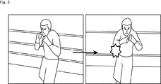
- the image processing device 12 displays an image as shown in FIG.
- the image in FIG. 2 is an image of a first-person viewpoint boxing game (content) in which a user wearing the HMD 11 is a player.
- the image displayed on the HMD 11 may be a 2D image.
- a 3D image is displayed in a three-dimensional manner by displaying a right-eye image to be shown to the user's right eye and a left-eye image to be shown to the user's left eye. It may be an image.
- the image processing apparatus 12 reduces discomfort such as “VR sickness” in a state where the user visually observes the image displayed on the HMD 11 and experiences the virtual world. An image is generated so as to be displayed on the HMD 11.
- the HMD 11, the image processing device 12, and the controller 13 may be combined as necessary, and the image system 1 may be configured by one or two devices.
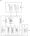
- FIG. 3 is a block diagram illustrating a detailed configuration example of the image system 1.
- the HMD 11 includes a sensor 41 and a display unit 42.
- the sensor 41 is composed of a combination of one or more sensor elements such as a gyro sensor, an acceleration sensor, and a geomagnetic sensor, and detects the position and direction of the user's head.
- the sensor 41 is a sensor that can detect a total of nine axes including a three-axis gyro sensor, a three-axis acceleration sensor, and a three-axis geomagnetic sensor.
- the sensor 41 supplies the detected result to the image processing device 12.
- the display unit 42 is composed of, for example, an organic EL (Electro-Luminescence) element or a liquid crystal display, and displays a predetermined image based on an image signal supplied from the image processing device 12.
- organic EL Electro-Luminescence
- the HMD 11 may include a speaker that outputs sound, a microphone that acquires user's sound, and the like.
- the controller 13 includes an operation unit 81 including a plurality of operation buttons, receives a user operation, and supplies a predetermined instruction corresponding to the user operation to the image processing apparatus 12.
- the image processing apparatus 12 includes at least a storage unit 61 and an image generation unit 62.
- the image generation unit 62 includes an avatar operation control unit 71, a user posture detection unit 72, a posture difference calculation unit 73, and a presentation image generation unit 74. Consists of.
- the storage unit 61 is composed of, for example, a hard disk or a non-volatile memory, and stores a program for controlling the operation of the image processing apparatus 12, content (program) for displaying an image on the HMD 11, and the like.
- the avatar operation control unit 71 controls the operation (attitude) of the avatar corresponding to the user in the image (content image) on the virtual world displayed on the display unit 42.
- the control of the avatar's motion (posture) also takes into account the actual user posture (actual user posture) detected by the user posture detector 72.
- the avatar's operation changes depending on, for example, an operation selected by the user, an action performed by the user, or the like in the virtual world content image displayed on the display unit 42.
- the user posture detection unit 72 detects the actual posture of the user based on the detection result of the position and direction of the user's head supplied from the sensor 41.
- the posture difference calculation unit 73 calculates a posture difference between the avatar posture determined by the avatar motion control unit 71 and the actual posture of the user detected by the user posture detection unit 72.
- the presentation image generation unit 74 generates a presentation image that is a content image acquired from the storage unit 61 and is presented to the user, and supplies the generated presentation image to the display unit 42.
- the presentation image includes the actions of the user's own avatar and the other person's avatar determined by the avatar movement control unit 71, the actual posture of the user determined by the user attitude detection unit 72, and the avatar determined by the attitude difference calculation unit 73. It is generated based on the posture and the posture difference between the user's actual posture.
- the presentation image generation unit 74 matches the posture of the avatar with the actual posture of the user and generates the presentation image (first presentation image) so that the image from the viewpoint of the avatar is presented to the user. Under predetermined conditions, in order to reduce user discomfort such as “VR sickness”, an image different from the avatar viewpoint image is generated as a presentation image (second presentation image) and displayed on the display unit 42. .
- the avatar's posture is a three-dimensional position ( x, y, z) and two parameters (x, y, z, ⁇ , ⁇ ) consisting of two-dimensional directions ( ⁇ , ⁇ ).
- the three-dimensional position (x, y, z) corresponds to the position of the head of the avatar on the virtual world
- the two-dimensional direction ( ⁇ , ⁇ ) is the line-of-sight direction (head) of the avatar on the virtual world.
- the direction ⁇ is an angle formed by the line-of-sight direction with respect to a predetermined reference axis (Z axis in the example of B in FIG. 4) on the XZ plane, which is a so-called azimuth angle.
- the direction ⁇ is an angle in the Y-axis direction formed by the line-of-sight direction with respect to the XZ plane, as shown in FIG. Therefore, the posture in the present specification includes not only the head position in the virtual world but also the line-of-sight direction.
- a user posture pos u (x u , yu , z u , ⁇ u , ⁇ u )
- Avatar posture pos a (x a , y a , z a , ⁇ a , ⁇ a )
- Presented image posture pos v (x v , y v , z v , ⁇ v , ⁇ v )
- the user posture pos u is a projection of the actual posture of the user determined by the detection result supplied from the sensor 41 on the virtual world.
- the avatar posture pos a is a representation of the avatar posture with coordinates in the virtual world.
- the presented image posture pos v is a virtual posture corresponding to the presented image displayed on the display unit 42.
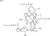
- the three postures of the user posture pos u , the avatar posture pos a , and the presented image posture pos v will be specifically described.
- the user posture pos u (x u , yu , z u calculated by the user posture detector 72. , ⁇ u , ⁇ u ) is the posture 101.
- the avatar posture pos a (x a , y a , z a , ⁇ a , ⁇ a ) controlled by the avatar motion control unit 71 becomes the posture 102 that has fallen to the ground as shown in FIG.
- the virtual world image from the avatar's viewpoint is used as the presentation image.
- the presentation image is changed greatly in accordance with the abrupt movement of the avatar, the user will experience “VR sickness”. There is a fear.
- the presentation image generation unit 74 does not correspond to the image corresponding to the avatar posture pos a (the posture 102 in FIG. 5), for example, the image 111 corresponding to the posture 103 close to the actual posture of the user (the posture 101 in FIG. 5). It produces
- the image 111 as the presentation image is an image whose field of view changes more slowly than the image corresponding to the avatar posture pos a .
- the presentation image posture pos v is different from both the avatar posture pos a and the user posture pos u in a scene on which VR sickness is reduced, but the presented image is at least a normal scene. Any image different from the avatar viewpoint image that is the presented image may be used.
- the presented image may be an image corresponding to the actual posture of the user.
- step S ⁇ b > 1 the avatar motion control unit 71 determines the avatar motion (avatar posture pos a ) in the virtual world displayed on the display unit 42. In addition, when another avatar other than the player himself / herself appears in the virtual world, the operation (posture) of the other person's avatar is also determined. After step S1, the determination of the avatar's operation is always executed according to the content.
- step S2 the user posture detector 72, supplied from the sensor 41, based on the sensor detection result indicating the position and direction of the user's head, to detect the actual attitude pos u users. Detection of the actual attitude pos u of the user based on the sensor detection results is performed at all times subsequent.
- the detected actual posture pos u of the user is supplied to the avatar motion control unit 71, and the motion (posture) of the avatar is matched with the motion of the user.
- step S ⁇ b> 3 the presentation image generation unit 74 generates an avatar viewpoint image that is an image from the avatar viewpoint as a presentation image, and supplies the display image to the display unit 42 of the HMD 11 for display.
- step S4 the posture difference calculation unit 73 calculates a posture difference between the avatar posture pos a determined by the avatar motion control unit 71 and the actual posture pos u of the user detected by the user posture detection unit 72, This is supplied to the presentation image generation unit 74.
- step S ⁇ b > 5 the presentation image generation unit 74 determines whether the posture difference between the avatar posture pos a and the user's actual posture pos u is greater than or equal to a predetermined first range.
- a threshold thres azimuthal theta theta and sets a threshold thres phi elevation phi either of the following conditions of Equation (1) or (2)
- the presentation image generation unit 74 can determine that the posture difference between the avatar posture pos a and the user's actual posture pos u is equal to or greater than the first range.
- in Equation (1) and Equation (2) represents the absolute value of d.
- Thres ⁇ in the equation (1) is a threshold value for the azimuth angle ⁇
- thres ⁇ in the equation (2) is a threshold value for the elevation angle ⁇ .
- Arbitrary values can be set as the threshold value thres ⁇ and the threshold value thres ⁇ .
- the threshold value can be set to 30 degrees. This numerical value of 30 degrees means that the average person moves the line of sight by moving only the eyeball if it is within 30 degrees when looking at an object in a direction deviated from the front, but the direction deviated further It is a numerical value that naturally moves the head when looking at the object in.
- the threshold value thres ⁇ and the threshold value thres ⁇ can be set to 1 degree. This is because the central area of the retina, called the fovea, used when looking at the details of things is said to be about 1 degree for the average person.
- the threshold value thres ⁇ and the threshold value thres ⁇ can be changed to values desired by the user using a setting screen or the like. By changing these threshold values, the degree of sickness prevention can be controlled.
- the determination condition described above is a condition for mainly determining that the orientation of the head has been moved.
- the expressions (1) and (2) The following condition of the formula (3) can be added. That is, when any one of the expressions (1) to (3) is satisfied, it is determined that the attitude difference between the avatar attitude pos a and the user's actual attitude pos u is greater than or equal to the first range. ⁇ x au > thres x (3)
- the moving speed of the avatar's head position or the angular speed in the line-of-sight direction may be used.
- the attitude difference between the avatar attitude pos a and the user's actual attitude pos u is greater than or equal to the first range.
- step S5 not only has the phenomenon that the posture difference between the avatar posture pos a and the user's actual posture pos u is determined to be greater than or equal to the first range once, but also when a predetermined number of times has occurred, Or you may make it determine with an attitude
- step S5 If it is determined in step S5 that the posture difference between the avatar posture pos a and the user's actual posture pos u is not greater than or equal to the first range, the process returns to step S3, and the above-described steps S3 to S5 are repeated. It is.
- step S5 if it is determined in step S5 that the posture difference between the avatar posture pos a and the user's actual posture pos u is greater than or equal to the first range, the process proceeds to step S6, and the presentation image generation unit 74 A reduced processing image for reducing discomfort such as “VR sickness” is generated as an image and supplied to the display unit 42 for display.
- the presentation image generation unit 74 generates and displays, for example, an image corresponding to the user posture pos u as the reduction processing image.
- the presented image posture pos v is the user posture pos u .
- the presentation image generation unit 74 sets the head position and the azimuth angle ⁇ of the presentation image posture pos v as the head position and the azimuth angle ⁇ of the avatar posture pos a as the reduction processing image, for example.
- the elevation angle ⁇ of v an image having the elevation angle ⁇ of the user posture pos u is generated and displayed. That is, the presentation image posture pos v is as follows.
- the head position and the elevation angle ⁇ of the presentation image posture pos v are set to the head position and the elevation angle ⁇ of the avatar posture pos a
- the azimuth angle ⁇ of the presentation image posture pos v is the user posture.
- An image having the azimuth angle ⁇ of pos u may be generated and displayed. That is, the presentation image posture pos v is as follows.
- step S ⁇ b > 7 the presentation image generation unit 74 determines whether or not the posture difference between the avatar posture pos a and the user's actual posture pos u is within a predetermined second range.
- step S7 the posture difference between the avatar posture pos a and the user's actual posture pos u is not yet within the second range, that is, the posture difference between the avatar posture pos a and the user's actual posture pos u is If it is determined that the range is greater than 2, the process returns to step S6, and the above-described process is repeated. That is, the reduction processing image is continuously generated as the presentation image and displayed on the display unit 42.
- step S7 if it is determined in step S7 that the posture difference between the avatar posture pos a and the user's actual posture pos u is within the second range, the process proceeds to step S8, and the presentation image generation unit 74 reduces the reduction.
- the processed image is generated so as to gradually approach the avatar viewpoint image (image corresponding to the avatar posture pos a ), and is displayed on the display unit 42.
- simple linear motion, curved motion such as Bezier, body model, and the like can be used for the control of the presented image posture pos v that continuously brings the presented image (reduction processing image) close to the avatar viewpoint image, which is the processing in step S8.
- Calculations based on motion within the driving range allowed by the geometric constraint based on the above can be used.
- step S8 the process returns to step S3, and steps S3 to S8 described above are executed again.
- the values in the first range and the second range may be the same value or different values.
- the above processing is executed as the presentation image generation processing.
- the presentation image generation unit 74 has a case where the posture difference between the avatar posture pos a and the user's actual posture pos u is smaller than a predetermined threshold (first range). Then, an avatar viewpoint image (an image corresponding to the avatar posture pos a ) based on the avatar's viewpoint is generated as a first presentation image, and the posture difference between the avatar posture pos a and the user's actual posture pos u is a predetermined threshold (first And a reduction processing image different from the avatar viewpoint image is generated as the second presentation image and displayed when the posture difference of a certain level or more occurs between the avatar posture pos a and the actual posture pos u of the user. This is displayed on the unit 42. Thereby, user discomfort such as “VR sickness” can be reduced.
- a predetermined threshold first range
- the reduction processing image is generated and displayed using the content image in the virtual world.
- the entire screen is a black image (blackout screen) or the like.
- an image different from the currently displayed content image may be displayed, such as a reminder screen explaining that the screen is being changed to prevent “sickness”.
- the black image and the avatar viewpoint image can be returned to the avatar viewpoint image by using, for example, an alpha blend process for alpha blending.
- the reduced processed image I u in step S8 is expressed by the following equation (9) using the blend rate ⁇ (0 ⁇ ⁇ ⁇ 1).
- I u ⁇ I a + (1 ⁇ ) I b (9)
- the black image can be controlled to gradually return to the original avatar viewpoint image.
- Example of content sharing a virtual world with multiple users The above-described example is an example in which one user experiences a virtual world. However, a plurality of users may share and experience the same virtual world.
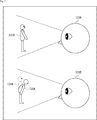
- the avatar 131B of the other user 121B is displayed and displayed on the HMD 11 of the other user 121B. It is assumed that there is a scene in which the avatar 131A of one user 121A is displayed on the virtual world (presented image).
- the avatar 131A of the user 121A operates in the virtual world based on the sensor detection result of the user 121A.
- the avatar 131B of the user 121B operates in the virtual world based on the sensor detection result of the user 121B.
- the avatar 131 (131A, 131B) operates in the same manner as the operation of the user 121 (121A, 121B), but may perform an operation that does not match the operation of the user 121 as a content design. is there.
- the actual user 121A may bow, but since the user 121B cannot see the actual user 121A, the avatar 131A that the user 121B sees in the virtual world may be bowed. . Therefore, the user 121A gives an operation instruction to bow the avatar 131A by operating the controller 13 or inputting a voice.
- a presentation image in which the avatar 131A of the user 121A performs a bowing operation is displayed on the display unit 42 of the HMD 11 worn by the user 121B.
- the posture difference between the avatar posture pos a and the actual posture pos u of the user 121A is greater than or equal to the first range. Therefore, as a process of step S6 in FIG.
- the unit 74 generates a reduction processing image and displays it on the display unit 42 of the HMD 11 worn by the user 121A.
- the field of view changes greatly and “drunk” occurs. Can be switched.
- the avatar posture of the avatar 131A of the presented image is processed as step S8 in FIG. pos a is controlled so as to gradually approach the actual posture pos u of the user 121A.
- a prepared presentation image may be displayed according to the operation command.
- an image different from the avatar viewpoint image is displayed with respect to an operation command in a case where a posture difference between the user's actual posture pos u and the avatar posture pos a is generated based on the detection result of detecting the user's movement.
- VR sickness can be suppressed.
- ⁇ Computer configuration example> The series of processes described above can be executed by hardware or can be executed by software.
- a program constituting the software is installed in the computer.
- the computer includes, for example, a general-purpose personal computer that can execute various functions by installing a microcomputer incorporated in dedicated hardware and various programs.
- FIG. 8 is a block diagram showing an example of the hardware configuration of a computer that executes the above-described series of processing by a program.
- a CPU Central Processing Unit
- ROM Read Only Memory
- RAM Random Access Memory
- An input / output interface 205 is further connected to the bus 204.
- An input unit 206, an output unit 207, a storage unit 208, a communication unit 209, and a drive 210 are connected to the input / output interface 205.
- the input unit 206 includes a keyboard, a mouse, a microphone, and the like.
- the output unit 207 includes a display, a speaker, and the like.
- the storage unit 208 includes a hard disk, a nonvolatile memory, and the like.
- the communication unit 209 includes a network interface and the like.
- the drive 210 drives a removable recording medium 211 such as a magnetic disk, an optical disk, a magneto-optical disk, or a semiconductor memory.
- the CPU 201 loads, for example, the program stored in the storage unit 208 to the RAM 203 via the input / output interface 205 and the bus 204 and executes the program. Is performed.
- the program can be installed in the storage unit 208 via the input / output interface 205 by attaching the removable recording medium 211 to the drive 210. Further, the program can be received by the communication unit 209 via a wired or wireless transmission medium such as a local area network, the Internet, or digital satellite broadcasting, and can be installed in the storage unit 208. In addition, the program can be installed in the ROM 202 or the storage unit 208 in advance.
- the program executed by the computer may be a program that is processed in time series in the order described in this specification, or in parallel or at a necessary timing such as when a call is made. It may be a program for processing.
- the system means a set of a plurality of components (devices, modules (parts), etc.), and it does not matter whether all the components are in the same housing. Accordingly, a plurality of devices housed in separate housings and connected via a network and a single device housing a plurality of modules in one housing are all systems. .
- Embodiments of the present technology are not limited to the above-described embodiments, and various modifications can be made without departing from the gist of the present technology.
- HMD head mounted display
- HUD head up display
- dome-shaped (hemispherical) display or the like may be used. Any display device that displays video so as to cover the user's field of view may be used.
- This technology can take the configuration of cloud computing in which one function is shared by a plurality of devices via a network and is jointly processed.
- each step described in the above flowchart can be executed by one device or can be shared by a plurality of devices.
- the plurality of processes included in the one step can be executed by being shared by a plurality of apparatuses in addition to being executed by one apparatus.
- An avatar viewpoint image based on an avatar viewpoint corresponding to a user on the virtual world is generated as a first presentation image to be presented to the user, and the actual posture of the user based on a detection result of detecting the user's movement;
- An image processing apparatus comprising: an image generation unit configured to generate a second presentation image different from the avatar viewpoint image when a posture difference from the avatar posture occurs.
- the posture is defined by a head position and a line-of-sight direction, The image generation unit generates a second presentation image different from the avatar viewpoint image when a difference between an azimuth angle or an elevation angle between the real posture of the user and the posture of the avatar is equal to or greater than a first threshold. ).
- the posture is defined by a head position and a line-of-sight direction
- the image generation unit is configured such that a difference between an azimuth angle or an elevation angle between the user's actual posture and the avatar's posture is equal to or greater than a first threshold, or a head position between the user's actual posture and the avatar's posture.
- the image processing apparatus according to (1) wherein when the difference is equal to or greater than a first threshold, a second presentation image different from the avatar viewpoint image is generated.
- the second presentation image is an image corresponding to the posture of the user.
- the image processing apparatus according to any one of (1) to (3), wherein the second presentation image is an image corresponding to a head position of the avatar posture and a line-of-sight direction of the user posture.
- the second presentation image is an image corresponding to a head position and an azimuth angle of the avatar posture and an elevation angle of the user posture.
- the second presentation image is an image corresponding to a head position and an elevation angle of the avatar posture and an azimuth angle of the user posture.
- the image generation unit is configured to output a second difference from the avatar viewpoint image when a case where a difference in posture between the actual posture of the user and the posture of the avatar is equal to or more than a first threshold occurs for a predetermined number of times or for a predetermined time.
- the image processing apparatus according to any one of (1) to (7).
- the image generation unit further displays the second presentation image so as to gradually approach the avatar viewpoint image when the posture difference between the real posture of the user and the posture of the avatar is within a second threshold.
- the image processing device according to any one of (1) to (8).
- the image generation unit receives a second presentation different from the avatar viewpoint image when the avatar is operated in response to an instruction from the operation unit to cause a difference in posture between the actual posture of the user and the posture of the avatar.
- the image processing device according to any one of (1) to (9), which generates an image.
- the image processing device An avatar viewpoint image based on an avatar viewpoint corresponding to a user on the virtual world is generated as a first presentation image to be presented to the user, and the actual posture of the user based on a detection result of detecting the user's movement;
- An image processing method including a step of generating a second presentation image different from the avatar viewpoint image when an attitude difference from the avatar attitude occurs.
- An avatar viewpoint image based on an avatar viewpoint corresponding to a user on the virtual world is generated as a first presentation image to be presented to the user, and the actual posture of the user based on a detection result of detecting the user's movement;
- An image generation unit that generates a second presentation image different from the avatar viewpoint image when an attitude difference from the avatar attitude occurs;
- An image system comprising: a display unit that displays the first presentation image and the second presentation image.
Abstract
The present art relates to an image processing device, an image processing method, and an image system capable of reducing the discomfort of a user, such as "VR sickness". The image processing device is provided with an image generation unit that generates, as a first presentation image to be presented to a user, an avatar viewpoint image based on the viewpoint of an avatar corresponding to the user in a virtual world, and that generates a second presentation image different from the avatar viewpoint image when a posture difference occurs between the actual posture of the user based on the result of detecting the motion of the user, and the posture of the avatar. The present art is applicable, for example, to an image processing device for generating an image to be displayed on a head mounted display.
Description
本技術は、画像処理装置、画像処理方法、および画像システムに関し、特に、「VR酔い」等のユーザの不快感を軽減することができるようにした画像処理装置、画像処理方法、および画像システムに関する。
The present technology relates to an image processing device, an image processing method, and an image system, and more particularly to an image processing device, an image processing method, and an image system that can reduce user discomfort such as “VR sickness”. .
近年、ヘッドマウントディスプレイやヘッドアップディスプレイは、広視野角な映像提示が可能になってきており、体や頭部の姿勢に応じて、表示させる映像の方向や姿勢を自然に変化・追従(トラッキング)させることにより、より臨場感の高い1人称視点体験が実現可能になってきている。1人称視点は、ビデオゲームの世界では特にファーストパーソン・シューティング(F.P.S.)などと呼ばれ、人気が出始めている。
In recent years, head-mounted displays and head-up displays have made it possible to present images with a wide viewing angle, and the direction and posture of the displayed image can be changed and tracked naturally according to the posture of the body and head (tracking). ), It is becoming possible to realize a first-person viewpoint experience with higher presence. The first person view, especially in the video game world, is called First Person Shooter (F.P.S.) and is becoming popular.
一方で、ヘッドマウントディスプレイやヘッドアップディスプレイを用いたバーチャルリアリティ(VR)体験をしたときに、一部のユーザが「VR酔い」や「映像酔い」と呼ばれる不快感を催す事例があることが知られている。これは、ユーザが体感したり、経験から予測している感覚と実際の感覚(例えば視覚刺激)にずれがあると発生すると言われている。
On the other hand, when experiencing a virtual reality (VR) experience using a head-mounted display or a head-up display, it is known that some users experience discomfort called “VR sickness” or “video sickness”. It has been. This is said to occur when there is a discrepancy between the sensation experienced by the user or the actual sensation predicted from experience (for example, visual stimulation).
この「VR酔い」や「映像酔い」の不快感を軽減させるための工夫が提案されている(例えば、特許文献1参照)。
A device for reducing the unpleasant feeling of “VR sickness” and “video sickness” has been proposed (for example, see Patent Document 1).
しかしながら、このような「VR酔い」等の不快感に対する対策がさらに求められている。
However, there is a further demand for measures against such unpleasant feelings such as “VR sickness”.
本技術は、このような状況に鑑みてなされたものであり、「VR酔い」等のユーザの不快感を軽減することができるようにするものである。
This technology has been made in view of such a situation, and is intended to reduce user discomfort such as “VR sickness”.
本技術の一側面の画像処理装置は、仮想世界上のユーザに相当するアバタの視点によるアバタ視点画像を、前記ユーザに提示する第1の提示画像として生成し、前記ユーザの動きを検出した検出結果に基づく前記ユーザの実姿勢と、前記アバタの姿勢との姿勢差が生じる場合、前記アバタ視点画像と異なる第2の提示画像を生成する画像生成部を備える。
An image processing apparatus according to an aspect of the present technology generates an avatar viewpoint image based on an avatar viewpoint corresponding to a user in a virtual world as a first presentation image to be presented to the user, and detects the movement of the user When a posture difference between the actual posture of the user based on the result and the posture of the avatar occurs, an image generation unit is provided that generates a second presentation image different from the avatar viewpoint image.
本技術の一側面の画像処理方法は、画像処理装置が、仮想世界上のユーザに相当するアバタの視点によるアバタ視点画像を、前記ユーザに提示する第1の提示画像として生成し、前記ユーザの動きを検出した検出結果に基づく前記ユーザの実姿勢と、前記アバタの姿勢との姿勢差が生じる場合、前記アバタ視点画像と異なる第2の提示画像を生成するステップを含む。
In the image processing method according to one aspect of the present technology, the image processing apparatus generates an avatar viewpoint image based on an avatar viewpoint corresponding to the user in the virtual world as a first presentation image to be presented to the user, and A step of generating a second presentation image different from the avatar viewpoint image when there is a posture difference between the actual posture of the user based on the detection result of detecting the motion and the posture of the avatar;
本技術の一側面の画像システムは、仮想世界上のユーザに相当するアバタの視点によるアバタ視点画像を、前記ユーザに提示する第1の提示画像として生成し、前記ユーザの動きを検出した検出結果に基づく前記ユーザの実姿勢と、前記アバタの姿勢との姿勢差が生じる場合、前記アバタ視点画像と異なる第2の提示画像を生成する画像生成部と、前記第1の提示画像および前記第2の提示画像を表示する表示部とを備える。
An image system according to an aspect of the present technology generates an avatar viewpoint image based on an avatar viewpoint corresponding to a user on a virtual world as a first presentation image to be presented to the user, and detects a detection result of the user's movement An image generation unit that generates a second presentation image different from the avatar viewpoint image, when the posture difference between the actual posture of the user based on the image and the posture of the avatar occurs, the first presentation image and the second A display unit for displaying the presented image.
本技術の一側面においては、仮想世界上のユーザに相当するアバタの視点によるアバタ視点画像が、前記ユーザに提示する第1の提示画像として生成され、前記ユーザの動きを検出した検出結果に基づく前記ユーザの実姿勢と、前記アバタの姿勢との姿勢差が生じる場合、前記アバタ視点画像と異なる第2の提示画像が生成される。
In one aspect of the present technology, an avatar viewpoint image based on an avatar viewpoint corresponding to a user in the virtual world is generated as a first presentation image to be presented to the user, and is based on a detection result of detecting the user's movement. When a posture difference between the actual posture of the user and the posture of the avatar occurs, a second presentation image different from the avatar viewpoint image is generated.
なお、本技術の一側面の画像処理装置は、コンピュータにプログラムを実行させることにより実現することができる。
Note that the image processing apparatus according to one aspect of the present technology can be realized by causing a computer to execute a program.
また、本技術の一側面の画像処理装置を実現するために、コンピュータに実行させるプログラムは、伝送媒体を介して伝送することにより、又は、記録媒体に記録して、提供することができる。
Also, in order to realize the image processing apparatus according to one aspect of the present technology, a program to be executed by a computer can be provided by being transmitted via a transmission medium or by being recorded on a recording medium.
画像処理装置は、独立した装置であっても良いし、1つの装置を構成している内部ブロックであっても良い。
The image processing apparatus may be an independent apparatus or an internal block constituting one apparatus.
本技術の一側面によれば、「VR酔い」等のユーザの不快感を軽減することができる。
According to one aspect of the present technology, user discomfort such as “VR sickness” can be reduced.
なお、ここに記載された効果は必ずしも限定されるものではなく、本開示中に記載されたいずれかの効果であってもよい。
It should be noted that the effects described here are not necessarily limited, and may be any of the effects described in the present disclosure.
以下、本技術を実施するための形態(以下、実施の形態という)について説明する。
Hereinafter, modes for carrying out the present technology (hereinafter referred to as embodiments) will be described.
<画像システムの構成例>
図1は、本技術を適用した画像システムの一実施の形態の構成例を示している。 <Example of image system configuration>
FIG. 1 shows a configuration example of an embodiment of an image system to which the present technology is applied.
図1は、本技術を適用した画像システムの一実施の形態の構成例を示している。 <Example of image system configuration>
FIG. 1 shows a configuration example of an embodiment of an image system to which the present technology is applied.
図1の画像システム1は、ヘッドマウントディスプレイ11(以下、HMD11と記述する。)、画像処理装置12、および、コントローラ13により構成される。
1 is composed of a head mounted display 11 (hereinafter referred to as HMD 11), an image processing device 12, and a controller 13.
HMD11は、画像処理装置12で生成された、仮想世界上の画像を表示し、ユーザに提示する。画像処理装置12は、HMD11に表示させる画像を生成し、HMD11に供給する。コントローラ13は、複数の操作ボタン(不図示)を備え、ユーザの操作を受け付けて、ユーザの操作に応じた所定の指示を画像処理装置12に供給する。
The HMD 11 displays an image on the virtual world generated by the image processing device 12 and presents it to the user. The image processing device 12 generates an image to be displayed on the HMD 11 and supplies the image to the HMD 11. The controller 13 includes a plurality of operation buttons (not shown), receives a user operation, and supplies a predetermined instruction corresponding to the user operation to the image processing apparatus 12.
HMD11と画像処理装置12との間、画像処理装置12とコントローラ13との間は、例えばHDMI(登録商標)(High Definition Multimedia Interface)やMHL(Mobile High-definition Link)などの有線ケーブル、あるいは、Wi-Fi(Wireless Fidelity)、wirelessHDやMiracastのような無線通信により接続される。
Between the HMD 11 and the image processing device 12, between the image processing device 12 and the controller 13, for example, a wired cable such as HDMI (registered trademark) (High Definition Multimedia Interface) or MHL (Mobile High-definition Link), or Connection is established by wireless communication such as Wi-Fi (Wireless Fidelity), wirelessHD, and Miracast.
本実施の形態では、例えば、画像処理装置12は、図2に示されるような画像を表示させる。図2の画像は、HMD11を装着しているユーザをプレーヤとした1人称視点のボクシングゲーム(コンテンツ)の画像である。HMD11に表示される画像は、2D画像でもよし、ユーザの右眼に見せるための右眼用画像と、ユーザの左眼に見せるための左眼用画像を表示して、立体的に視認させる3D画像でもよい。
In the present embodiment, for example, the image processing device 12 displays an image as shown in FIG. The image in FIG. 2 is an image of a first-person viewpoint boxing game (content) in which a user wearing the HMD 11 is a player. The image displayed on the HMD 11 may be a 2D image. A 3D image is displayed in a three-dimensional manner by displaying a right-eye image to be shown to the user's right eye and a left-eye image to be shown to the user's left eye. It may be an image.
以上のように構成される画像システム1において、画像処理装置12は、ユーザがHMD11に表示された画像を視認して仮想世界を体験している状態において、「VR酔い」等の不快感を軽減させるように画像を生成して、HMD11に表示させる。
In the image system 1 configured as described above, the image processing apparatus 12 reduces discomfort such as “VR sickness” in a state where the user visually observes the image displayed on the HMD 11 and experiences the virtual world. An image is generated so as to be displayed on the HMD 11.
なお、HMD11、画像処理装置12、及び、コントローラ13は、必要に応じて合体されて、画像システム1が、1つまたは2つの装置で構成されてもよい。
Note that the HMD 11, the image processing device 12, and the controller 13 may be combined as necessary, and the image system 1 may be configured by one or two devices.
<画像システムの詳細構成例>
図3は、画像システム1の詳細構成例を示すブロック図である。 <Detailed configuration example of image system>
FIG. 3 is a block diagram illustrating a detailed configuration example of theimage system 1.
図3は、画像システム1の詳細構成例を示すブロック図である。 <Detailed configuration example of image system>
FIG. 3 is a block diagram illustrating a detailed configuration example of the
HMD11は、センサ41と表示部42を備える。
The HMD 11 includes a sensor 41 and a display unit 42.
センサ41は、例えば、ジャイロ・センサ、加速度センサ、地磁気センサなどの1以上のセンサ素子の組み合わせで構成され、ユーザの頭部の位置及び方向を検出する。本実施の形態では、センサ41は、3軸ジャイロ・センサ、3軸加速度センサ、3軸地磁気センサの合計9軸を検出可能なセンサであるとする。センサ41は、検出した結果を画像処理装置12に供給する。
The sensor 41 is composed of a combination of one or more sensor elements such as a gyro sensor, an acceleration sensor, and a geomagnetic sensor, and detects the position and direction of the user's head. In the present embodiment, it is assumed that the sensor 41 is a sensor that can detect a total of nine axes including a three-axis gyro sensor, a three-axis acceleration sensor, and a three-axis geomagnetic sensor. The sensor 41 supplies the detected result to the image processing device 12.
表示部42は、例えば有機EL(Electro-Luminescence)素子や液晶ディスプレイなどで構成され、画像処理装置12から供給される画像信号に基づいて所定の画像を表示する。
The display unit 42 is composed of, for example, an organic EL (Electro-Luminescence) element or a liquid crystal display, and displays a predetermined image based on an image signal supplied from the image processing device 12.
なお、HMD11には、音声出力を行うスピーカや、ユーザの音声を取得するマイクロホンなどがあってもよい。
Note that the HMD 11 may include a speaker that outputs sound, a microphone that acquires user's sound, and the like.
コントローラ13は、複数の操作ボタンを含む操作部81を備え、ユーザの操作を受け付けて、ユーザの操作に応じた所定の指示を画像処理装置12に供給する。
The controller 13 includes an operation unit 81 including a plurality of operation buttons, receives a user operation, and supplies a predetermined instruction corresponding to the user operation to the image processing apparatus 12.
画像処理装置12は、記憶部61と画像生成部62を少なくとも有し、画像生成部62は、アバタ動作制御部71、ユーザ姿勢検出部72、姿勢差算出部73、及び、提示画像生成部74により構成される。
The image processing apparatus 12 includes at least a storage unit 61 and an image generation unit 62. The image generation unit 62 includes an avatar operation control unit 71, a user posture detection unit 72, a posture difference calculation unit 73, and a presentation image generation unit 74. Consists of.
記憶部61は、例えば、ハードディスクや不揮発性のメモリなどで構成され、画像処理装置12の動作を制御するプログラムや、HMD11に画像を表示するためのコンテンツ(プログラム)などを記憶する。
The storage unit 61 is composed of, for example, a hard disk or a non-volatile memory, and stores a program for controlling the operation of the image processing apparatus 12, content (program) for displaying an image on the HMD 11, and the like.
アバタ動作制御部71は、表示部42に表示される仮想世界上の画像(コンテンツ画像)においてユーザに相当するアバタの動作(姿勢)を制御する。アバタの動作(姿勢)の制御には、ユーザ姿勢検出部72によって検出される、ユーザの実際の姿勢(ユーザの実姿勢)も考慮される。アバタの動作は、例えば、表示部42に表示された仮想世界のコンテンツ画像において、ユーザが選択した動作や、ユーザが行ったアクション等によって変化する。
The avatar operation control unit 71 controls the operation (attitude) of the avatar corresponding to the user in the image (content image) on the virtual world displayed on the display unit 42. The control of the avatar's motion (posture) also takes into account the actual user posture (actual user posture) detected by the user posture detector 72. The avatar's operation changes depending on, for example, an operation selected by the user, an action performed by the user, or the like in the virtual world content image displayed on the display unit 42.
アバタ動作制御部71は、例えば、図2に示したボクシングゲームの対戦相手のように、表示部42に表示される画像にプレーヤ本人以外のアバタが登場する場合には、他人のアバタの動作(姿勢)も制御する。以下では、ユーザ本人のアバタと、他人のアバタを区別するため、他人のアバタを意味する場合は、他人アバタと称することとして、単にアバタと称する場合には、ユーザ本人のアバタを意味するものとする。
When an avatar other than the player appears in the image displayed on the display unit 42, for example, like the opponent of the boxing game shown in FIG. (Attitude) is also controlled. In the following, in order to distinguish the user's own avatar from the other person's avatar, when referring to the other person's avatar, when referring to the other person's avatar, when simply referring to the avatar, it means the user's own avatar To do.
ユーザ姿勢検出部72は、センサ41から供給される、ユーザの頭部の位置及び方向の検出結果に基づいて、ユーザの実姿勢を検出する。
The user posture detection unit 72 detects the actual posture of the user based on the detection result of the position and direction of the user's head supplied from the sensor 41.
姿勢差算出部73は、アバタ動作制御部71によって決定されたアバタの姿勢と、ユーザ姿勢検出部72によって検出されたユーザの実姿勢との姿勢差を算出する。
The posture difference calculation unit 73 calculates a posture difference between the avatar posture determined by the avatar motion control unit 71 and the actual posture of the user detected by the user posture detection unit 72.
提示画像生成部74は、記憶部61から取得されたコンテンツの画像であって、ユーザに提示する提示画像を生成し、表示部42に供給する。提示画像は、アバタ動作制御部71によって決定されたユーザ本人のアバタと他人アバタの動作、ユーザ姿勢検出部72によって決定されたユーザの実姿勢、及び、姿勢差算出部73によって決定されたアバタの姿勢とユーザの実姿勢の姿勢差とに基づいて生成される。提示画像生成部74は、通常の場面では、ユーザの実姿勢にアバタの姿勢を合わせ、アバタの視点による画像がユーザに提示されるように提示画像(第1の提示画像)を生成するが、所定の条件下においては、「VR酔い」等のユーザの不快感を軽減させるため、アバタ視点の画像とは異なる画像を提示画像(第2の提示画像)として生成し、表示部42に表示させる。
The presentation image generation unit 74 generates a presentation image that is a content image acquired from the storage unit 61 and is presented to the user, and supplies the generated presentation image to the display unit 42. The presentation image includes the actions of the user's own avatar and the other person's avatar determined by the avatar movement control unit 71, the actual posture of the user determined by the user attitude detection unit 72, and the avatar determined by the attitude difference calculation unit 73. It is generated based on the posture and the posture difference between the user's actual posture. In the normal scene, the presentation image generation unit 74 matches the posture of the avatar with the actual posture of the user and generates the presentation image (first presentation image) so that the image from the viewpoint of the avatar is presented to the user. Under predetermined conditions, in order to reduce user discomfort such as “VR sickness”, an image different from the avatar viewpoint image is generated as a presentation image (second presentation image) and displayed on the display unit 42. .
<提示画像の説明>
図4及び図5を参照して、提示画像生成部74によって生成される提示画像についてさらに説明する。 <Description of the presentation image>
With reference to FIG.4 and FIG.5, the presentation image produced | generated by the presentationimage generation part 74 is further demonstrated.
図4及び図5を参照して、提示画像生成部74によって生成される提示画像についてさらに説明する。 <Description of the presentation image>
With reference to FIG.4 and FIG.5, the presentation image produced | generated by the presentation
初めに、図4を参照して、表示部42に表示されるコンテンツ内の仮想世界と、仮想世界上のアバタの姿勢を表現する座標系について説明する。
First, with reference to FIG. 4, a virtual world in the content displayed on the display unit 42 and a coordinate system representing the attitude of the avatar on the virtual world will be described.
図4のAに示されるように、表示部42に表示されるコンテンツ内の仮想世界をX軸、Y軸、及び、Z軸からなる3次元空間とすると、アバタの姿勢は、3次元位置(x,y,z)と2次元の方向(θ,φ)とからなる5つのパラメータ(x,y,z,θ,φ)で表現することができる。
As shown in A of FIG. 4, when the virtual world in the content displayed on the display unit 42 is a three-dimensional space including the X axis, the Y axis, and the Z axis, the avatar's posture is a three-dimensional position ( x, y, z) and two parameters (x, y, z, θ, φ) consisting of two-dimensional directions (θ, φ).
ここで、3次元位置(x,y,z)は、仮想世界上のアバタの頭部の位置に対応し、2次元の方向(θ,φ)は、仮想世界上のアバタの視線方向(頭部が向く方向)に対応する。方向θは、図4のBに示されるように、XZ平面上の所定の基準軸(図4のBの例ではZ軸)に対して視線方向がなす角であり、いわゆる方位角である。方向φは、図4のCに示されるように、XZ平面に対して視線方向がなすY軸方向の角であり、いわゆる仰角である。したがって、本明細書における姿勢には、仮想世界上の頭部位置だけでなく、視線方向も含まれる。
Here, the three-dimensional position (x, y, z) corresponds to the position of the head of the avatar on the virtual world, and the two-dimensional direction (θ, φ) is the line-of-sight direction (head) of the avatar on the virtual world. Corresponding direction). As shown in FIG. 4B, the direction θ is an angle formed by the line-of-sight direction with respect to a predetermined reference axis (Z axis in the example of B in FIG. 4) on the XZ plane, which is a so-called azimuth angle. The direction φ is an angle in the Y-axis direction formed by the line-of-sight direction with respect to the XZ plane, as shown in FIG. Therefore, the posture in the present specification includes not only the head position in the virtual world but also the line-of-sight direction.
表示部42に表示されるコンテンツの仮想世界において、ユーザ姿勢posu、アバタ姿勢posa、及び、提示画像姿勢posvの3つの姿勢を以下のように定義する。
ユーザ姿勢posu=(xu,yu,zu,θu,φu)
アバタ姿勢posa=(xa,ya,za,θa,φa)
提示画像姿勢posv=(xv,yv,zv,θv,φv) In the virtual world of the content displayed on thedisplay unit 42, three postures of a user posture pos u , an avatar posture pos a , and a presentation image posture pos v are defined as follows.
User posture pos u = (x u , yu , z u , θ u , φ u )
Avatar posture pos a = (x a , y a , z a , θ a , φ a )
Presented image posture pos v = (x v , y v , z v , θ v , φ v )
ユーザ姿勢posu=(xu,yu,zu,θu,φu)
アバタ姿勢posa=(xa,ya,za,θa,φa)
提示画像姿勢posv=(xv,yv,zv,θv,φv) In the virtual world of the content displayed on the
User posture pos u = (x u , yu , z u , θ u , φ u )
Avatar posture pos a = (x a , y a , z a , θ a , φ a )
Presented image posture pos v = (x v , y v , z v , θ v , φ v )
ユーザ姿勢posuとは、センサ41から供給される検出結果によって決定されるユーザの実姿勢を仮想世界上に投影したものである。アバタ姿勢posaとは、アバタの姿勢を仮想世界上の座標で表現したものである。提示画像姿勢posvは、表示部42に表示される提示画像に対応する仮想の姿勢である。
The user posture pos u is a projection of the actual posture of the user determined by the detection result supplied from the sensor 41 on the virtual world. The avatar posture pos a is a representation of the avatar posture with coordinates in the virtual world. The presented image posture pos v is a virtual posture corresponding to the presented image displayed on the display unit 42.
図5を参照して、ユーザ姿勢posu、アバタ姿勢posa、及び、提示画像姿勢posvの3つの姿勢について具体的に説明する。
With reference to FIG. 5, the three postures of the user posture pos u , the avatar posture pos a , and the presented image posture pos v will be specifically described.
図2に示したボクシングゲームのコンテンツの例で説明する。
Referring to the example of the boxing game content shown in FIG.
例えば、通常の場面では、ユーザ姿勢検出部72によって検出されるユーザの実姿勢に応じてアバタの姿勢が制御されるので、アバタ姿勢posaとユーザ姿勢posuは同一となる。つまり、アバタ姿勢posa=ユーザ姿勢posuである。また、表示部42に表示される提示画像は、アバタの視点からの仮想世界の画像となるので、提示画像姿勢posv=アバタ姿勢posaである。
For example, in a normal scene, the avatar attitude pos a and the user attitude pos u are the same because the avatar attitude is controlled according to the actual user attitude detected by the user attitude detector 72. That is, avatar posture pos a = user posture pos u . In addition, since the presentation image displayed on the display unit 42 is an image of the virtual world from the avatar's viewpoint, the presentation image posture pos v = avatar posture pos a .
したがって、「VR酔い」を軽減する特別な処理を行わない通常の場面では、
提示画像姿勢posv=アバタ姿勢posa=ユーザ姿勢posu
となる。 Therefore, in a normal scene where special processing to reduce “VR sickness” is not performed,
Presented image posture pos v = Avatar posture pos a = User posture pos u
It becomes.
提示画像姿勢posv=アバタ姿勢posa=ユーザ姿勢posu
となる。 Therefore, in a normal scene where special processing to reduce “VR sickness” is not performed,
Presented image posture pos v = Avatar posture pos a = User posture pos u
It becomes.
次に、例として、対戦相手のパンチによって、アバタがダウンした(地面に倒れた)場面を想定する。
Next, as an example, assume a scene where an avatar goes down (falls to the ground) due to an opponent's punch.
実際のユーザは地面に倒れておらず、図5の姿勢101のように立った姿勢であるとすると、ユーザ姿勢検出部72によって算出されるユーザ姿勢posu=(xu,yu,zu,θu,φu)は姿勢101となる。
Assuming that the actual user is not lying on the ground and is standing like the posture 101 in FIG. 5, the user posture pos u = (x u , yu , z u calculated by the user posture detector 72. , Θ u , φ u ) is the posture 101.
一方、アバタ動作制御部71によって制御されるアバタ姿勢posa=(xa,ya,za,θa,φa)は、図5に示される、地面に倒れた姿勢102となる。
On the other hand, the avatar posture pos a = (x a , y a , z a , θ a , φ a ) controlled by the avatar motion control unit 71 becomes the posture 102 that has fallen to the ground as shown in FIG.
通常の場面では、上述したように、アバタの視点からの仮想世界の画像を提示画像とするが、アバタの急激な移動に合わせて提示画像を大きく変化させると、ユーザが「VR酔い」をおこすおそれがある。
In normal scenes, as described above, the virtual world image from the avatar's viewpoint is used as the presentation image. However, if the presentation image is changed greatly in accordance with the abrupt movement of the avatar, the user will experience “VR sickness”. There is a fear.
そこで、提示画像生成部74は、アバタ姿勢posa(図5の姿勢102)に対応する画像ではなく、例えば、ユーザの実姿勢(図5の姿勢101)に近い姿勢103に対応する画像111を提示画像として生成し、表示部42に表示させる。提示画像としての画像111は、アバタ姿勢posaに対応する画像よりも視界変化が緩やかな画像である。提示画像となる画像111に対応する姿勢103が、提示画像姿勢posv=(xv,yv,zv,θv,φv)である。
Therefore, the presentation image generation unit 74 does not correspond to the image corresponding to the avatar posture pos a (the posture 102 in FIG. 5), for example, the image 111 corresponding to the posture 103 close to the actual posture of the user (the posture 101 in FIG. 5). It produces | generates as a presentation image and displays it on the display part 42. FIG. The image 111 as the presentation image is an image whose field of view changes more slowly than the image corresponding to the avatar posture pos a . The posture 103 corresponding to the image 111 to be the presented image is the presented image posture pos v = (x v , y v , z v , θ v , φ v ).
図5の例では、VR酔いを軽減する処理が施された場面では、提示画像姿勢posvは、アバタ姿勢posaとユーザ姿勢posuのいずれの姿勢とも異なるが、提示画像は、少なくとも通常場面の提示画像であるアバタ視点画像とは異なる画像であればよい。例えば、提示画像は、ユーザの実姿勢に対応する画像でもよい。
In the example of FIG. 5, the presentation image posture pos v is different from both the avatar posture pos a and the user posture pos u in a scene on which VR sickness is reduced, but the presented image is at least a normal scene. Any image different from the avatar viewpoint image that is the presented image may be used. For example, the presented image may be an image corresponding to the actual posture of the user.
<提示画像生成処理>
次に、図6のフローチャートを参照して、画像処理装置12による提示画像生成処理について説明する。この処理は、例えば、HMD11の表示部42に所定のコンテンツ画像を表示させる操作が行われたとき開始される。 <Presentation image generation processing>
Next, the presentation image generation processing by theimage processing device 12 will be described with reference to the flowchart of FIG. This process is started, for example, when an operation for displaying a predetermined content image on the display unit 42 of the HMD 11 is performed.
次に、図6のフローチャートを参照して、画像処理装置12による提示画像生成処理について説明する。この処理は、例えば、HMD11の表示部42に所定のコンテンツ画像を表示させる操作が行われたとき開始される。 <Presentation image generation processing>
Next, the presentation image generation processing by the
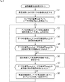
初めに、ステップS1において、アバタ動作制御部71は、表示部42に表示される仮想世界におけるアバタの動作(アバタ姿勢posa)を決定する。また、仮想世界上にプレーヤ本人以外の他人アバタが登場する場合には、他人アバタの動作(姿勢)も決定する。ステップS1以降、アバタの動作の決定は、コンテンツの内容に従って常時実行される。
First, in step S < b > 1, the avatar motion control unit 71 determines the avatar motion (avatar posture pos a ) in the virtual world displayed on the display unit 42. In addition, when another avatar other than the player himself / herself appears in the virtual world, the operation (posture) of the other person's avatar is also determined. After step S1, the determination of the avatar's operation is always executed according to the content.
ステップS2において、ユーザ姿勢検出部72は、センサ41から供給された、ユーザの頭部の位置及び方向を示すセンサ検出結果に基づいて、ユーザの実姿勢posuを検出する。センサ検出結果に基づくユーザの実姿勢posuの検出も、これ以降常時実行される。検出されたユーザの実姿勢posuはアバタ動作制御部71に供給され、アバタの動作(姿勢)が、ユーザの動作に合わせられる。
In step S2, the user posture detector 72, supplied from the sensor 41, based on the sensor detection result indicating the position and direction of the user's head, to detect the actual attitude pos u users. Detection of the actual attitude pos u of the user based on the sensor detection results is performed at all times subsequent. The detected actual posture pos u of the user is supplied to the avatar motion control unit 71, and the motion (posture) of the avatar is matched with the motion of the user.
ステップS3において、提示画像生成部74は、アバタの視点からの画像であるアバタ視点画像を提示画像として生成し、HMD11の表示部42に供給して表示させる。ここでの提示画像姿勢posvは、アバタ姿勢posa及びユーザ姿勢posuと等しくなる(提示画像姿勢posv=アバタ姿勢posa=ユーザ姿勢posu)。
In step S <b> 3, the presentation image generation unit 74 generates an avatar viewpoint image that is an image from the avatar viewpoint as a presentation image, and supplies the display image to the display unit 42 of the HMD 11 for display. The presented image posture pos v here is equal to the avatar posture pos a and the user posture pos u (presented image posture pos v = avatar posture pos a = user posture pos u ).
ステップS4において、姿勢差算出部73は、アバタ動作制御部71によって決定されたアバタ姿勢posaと、ユーザ姿勢検出部72によって検出されたユーザの実姿勢posuとの姿勢差を算出して、提示画像生成部74に供給する。
In step S4, the posture difference calculation unit 73 calculates a posture difference between the avatar posture pos a determined by the avatar motion control unit 71 and the actual posture pos u of the user detected by the user posture detection unit 72, This is supplied to the presentation image generation unit 74.
ステップS5において、提示画像生成部74は、アバタ姿勢posaとユーザの実姿勢posuとの姿勢差が、予め決定された第1の範囲以上であるかを判定する。
In step S < b > 5, the presentation image generation unit 74 determines whether the posture difference between the avatar posture pos a and the user's actual posture pos u is greater than or equal to a predetermined first range.
ここで、ステップS5における第1の範囲として、例えば、方位角θの閾値thresθおよび、仰角φの閾値thresφを設定し、以下の式(1)または式(2)のどちらかの条件を満たしたとき、提示画像生成部74は、アバタ姿勢posaとユーザの実姿勢posuとの姿勢差が第1の範囲以上であると判定することができる。式(1)及び式(2)の|d|は、dの絶対値を表す。
|θa-θu|>thresθ ・・・(1)
|φa-φu|>thresφ ・・・(2) Here, as a first range in step S5, for example, a threshold thres azimuthal theta theta and sets a threshold thres phi elevation phi, either of the following conditions of Equation (1) or (2) When satisfied, the presentationimage generation unit 74 can determine that the posture difference between the avatar posture pos a and the user's actual posture pos u is equal to or greater than the first range. | D | in Equation (1) and Equation (2) represents the absolute value of d.
| Θ a −θ u |> thres θ (1)
| Φ a −φ u |> thres φ (2)
|θa-θu|>thresθ ・・・(1)
|φa-φu|>thresφ ・・・(2) Here, as a first range in step S5, for example, a threshold thres azimuthal theta theta and sets a threshold thres phi elevation phi, either of the following conditions of Equation (1) or (2) When satisfied, the presentation
| Θ a −θ u |> thres θ (1)
| Φ a −φ u |> thres φ (2)
式(1)のthresθは、方位角θの閾値であり、式(2)のthresφは、仰角φの閾値である。閾値thresθ及び閾値thresφとしては、任意の値を設定することができるが、例えば、30度に設定することができる。この30度という数値は、平均的な人間は正面からずれた方向にある物体を見るときに30度以内であれば眼球のみを運動させることで視線方向を移動させるが、それ以上のずれた方向にある物体を見るときには自然と頭部の運動を行うという数値である。
Thres θ in the equation (1) is a threshold value for the azimuth angle θ, and thres φ in the equation (2) is a threshold value for the elevation angle φ. Arbitrary values can be set as the threshold value thres θ and the threshold value thres φ . For example, the threshold value can be set to 30 degrees. This numerical value of 30 degrees means that the average person moves the line of sight by moving only the eyeball if it is within 30 degrees when looking at an object in a direction deviated from the front, but the direction deviated further It is a numerical value that naturally moves the head when looking at the object in.
また、酔いを防止するための厳しい判定条件とする場合には、閾値thresθ及び閾値thresφは、1度に設定することができる。これは、ものの細部を注視するときに利用する中心窩と呼ばれる網膜中心部領域の範囲が、平均的な人間では約1度と言われることによる。閾値thresθ及び閾値thresφは、設定画面等を用いてユーザ所望の値に変更することができる。これらの閾値を変更することにより、酔い防止の程度を制御することができる。
Further, in the case of a strict determination condition for preventing sickness, the threshold value thres θ and the threshold value thres φ can be set to 1 degree. This is because the central area of the retina, called the fovea, used when looking at the details of things is said to be about 1 degree for the average person. The threshold value thres θ and the threshold value thres φ can be changed to values desired by the user using a setting screen or the like. By changing these threshold values, the degree of sickness prevention can be controlled.
上述した判定条件は、主に頭部の向きを動かされたことを判定する条件となるが、アバタが身体全体を大きく移動させられるケースも加味する場合には、式(1)及び式(2)の条件に加えて、次の式(3)の条件を加えることができる。すなわち、式(1)乃至式(3)のいずれかの条件を満たしたとき、アバタ姿勢posaとユーザの実姿勢posuとの姿勢差が第1の範囲以上であると判定する。
Δxau>thresx ・・・(3) The determination condition described above is a condition for mainly determining that the orientation of the head has been moved. However, when the case where the avatar can move the entire body is taken into account, the expressions (1) and (2) ), The following condition of the formula (3) can be added. That is, when any one of the expressions (1) to (3) is satisfied, it is determined that the attitude difference between the avatar attitude pos a and the user's actual attitude pos u is greater than or equal to the first range.
Δx au > thres x (3)
式(3)におけるΔxauは、ユーザの実姿勢posuの頭部位置(xu,yu,zu)と、アバタ姿勢posaの頭部位置(xa,ya,za)との差分を表し、Δxauとしては、式(4)の2次元ノルムや式(5)の1次元ノルムを採用することができる。thresxは、Δxauの閾値を表す。

[Delta] x au in the formula (3), the head position of the actual attitude pos u user (x u, y u, z u) and the head position of the avatar position pos a (x a, y a , z a) and As Δx au , the two-dimensional norm of Equation (4) or the one-dimensional norm of Equation (5) can be adopted. thres x represents a threshold value of Δx au .
その他のステップS5における判定条件としては、アバタの頭部位置の移動速度や視線方向の角速度を用いてもよい。具体的には、アバタの視線方向(θa,φa)の角速度をΔθ、Δφとし、アバタの頭部位置(xa,ya,za)の時間変化量(移動速度)をvaとして、式(6)乃至式(8)のいずれかの条件を満たしたとき、アバタ姿勢posaとユーザの実姿勢posuとの姿勢差が第1の範囲以上であると判定してもよい。
|Δθa-Δθa|>thresΔθ ・・・(6)
|Δφa-Δφa|>thresΔφ ・・・(7)
va>thresv ・・・(8) As other determination conditions in step S5, the moving speed of the avatar's head position or the angular speed in the line-of-sight direction may be used. Specifically, avatar gaze direction (θ a, φ a) Δθ angular velocities, and [Delta] [phi, the head position of the avatar (x a, y a, z a) time variation of the (movement speed) v a As described above, when any one of the expressions (6) to (8) is satisfied, it may be determined that the attitude difference between the avatar attitude pos a and the user's actual attitude pos u is greater than or equal to the first range. .
| Δθ a −Δθ a |> thres Δθ (6)
| Δφ a −Δφ a |> thres Δφ (7)
v a > thres v (8)
さらに、ステップS5では、アバタ姿勢posaとユーザの実姿勢posuとの姿勢差が第1の範囲以上であると判定される現象が1回発生しただけでなく、所定回数以上発生したとき、または、所定時間継続して発生したときに、姿勢差が第1の範囲以上であると判定するようにしてもよい。
Furthermore, in step S5, not only has the phenomenon that the posture difference between the avatar posture pos a and the user's actual posture pos u is determined to be greater than or equal to the first range once, but also when a predetermined number of times has occurred, Or you may make it determine with an attitude | position difference being more than a 1st range when it generate | occur | produces continuously for a predetermined time.
ステップS5で、アバタ姿勢posaとユーザの実姿勢posuとの姿勢差が第1の範囲以上ではないと判定された場合、処理はステップS3に戻り、上述したステップS3乃至S5の処理が繰り返される。これにより、アバタ姿勢posaとユーザの実姿勢posuとの姿勢差が第1の範囲より小さい場合には、アバタの視点からのアバタ視点画像が提示画像として表示され、提示画像姿勢posv=アバタ姿勢posaとなる。
If it is determined in step S5 that the posture difference between the avatar posture pos a and the user's actual posture pos u is not greater than or equal to the first range, the process returns to step S3, and the above-described steps S3 to S5 are repeated. It is. Thus, when the posture difference between the avatar posture pos a and the user's actual posture pos u is smaller than the first range, the avatar viewpoint image from the avatar's viewpoint is displayed as the presentation image, and the presentation image posture pos v = The avatar posture is pos a .
一方、ステップS5で、アバタ姿勢posaとユーザの実姿勢posuとの姿勢差が第1の範囲以上であると判定された場合、処理はステップS6に進み、提示画像生成部74は、提示画像として「VR酔い」等の不快感を軽減させるための軽減処理画像を生成し、表示部42に供給して表示させる。
On the other hand, if it is determined in step S5 that the posture difference between the avatar posture pos a and the user's actual posture pos u is greater than or equal to the first range, the process proceeds to step S6, and the presentation image generation unit 74 A reduced processing image for reducing discomfort such as “VR sickness” is generated as an image and supplied to the display unit 42 for display.
提示画像生成部74は、軽減処理画像として、例えば、ユーザ姿勢posuに対応する画像を生成して表示させる。この場合、提示画像姿勢posvは、ユーザ姿勢posuとなる。
posv=(xv,yv,zv,θv,φv)=(xu,yu,zu,θu,φu) The presentationimage generation unit 74 generates and displays, for example, an image corresponding to the user posture pos u as the reduction processing image. In this case, the presented image posture pos v is the user posture pos u .
pos v = (x v , y v , z v , θ v , φ v ) = (x u , yu , z u , θ u , φ u )
posv=(xv,yv,zv,θv,φv)=(xu,yu,zu,θu,φu) The presentation
pos v = (x v , y v , z v , θ v , φ v ) = (x u , yu , z u , θ u , φ u )
あるいはまた、提示画像生成部74は、軽減処理画像として、例えば、提示画像姿勢posvの頭部位置についてはアバタ姿勢posaの頭部位置とし、提示画像姿勢posvの視線方向についてはユーザ姿勢posuの視線方向とした画像を生成して表示させる。つまり、提示画像姿勢posvは、次のようになる。
posv=(xv,yv,zv,θv,φv)=(xa,ya,za,θu,φu) Alternatively, presenting theimage generator 74, as reduction process image, for example, a presentation image orientation pos v the head position of the avatar attitude pos a for the head position of the presentation image orientation pos v user orientation for viewing direction of An image with the line-of-sight direction of pos u is generated and displayed. That is, the presentation image posture pos v is as follows.
pos v = (x v , y v , z v , θ v , φ v ) = (x a , y a , z a , θ u , φ u )
posv=(xv,yv,zv,θv,φv)=(xa,ya,za,θu,φu) Alternatively, presenting the
pos v = (x v , y v , z v , θ v , φ v ) = (x a , y a , z a , θ u , φ u )
あるいはまた、提示画像生成部74は、軽減処理画像として、例えば、提示画像姿勢posvの頭部位置と方位角θについてはアバタ姿勢posaの頭部位置と方位角θとし、提示画像姿勢posvの仰角φについてはユーザ姿勢posuの仰角φとした画像を生成して表示させる。つまり、提示画像姿勢posvは、次のようになる。
posv=(xv,yv,zv,θv,φv)=(xa,ya,za,θa,φu)
これは、ユーザは、上下方向に意図せず視野を変更されるとより酔いやすいため、この方向にのみ、ユーザの視線方向を採用することを意味する。 Alternatively, the presentationimage generation unit 74 sets the head position and the azimuth angle θ of the presentation image posture pos v as the head position and the azimuth angle θ of the avatar posture pos a as the reduction processing image, for example. For the elevation angle φ of v , an image having the elevation angle φ of the user posture pos u is generated and displayed. That is, the presentation image posture pos v is as follows.
pos v = (x v, y v, z v, θ v, φ v) = (x a, y a, z a, θ a, φ u)
This means that the user is more likely to get drunk when the field of view is changed unintentionally in the vertical direction, and therefore, the user's line-of-sight direction is adopted only in this direction.
posv=(xv,yv,zv,θv,φv)=(xa,ya,za,θa,φu)
これは、ユーザは、上下方向に意図せず視野を変更されるとより酔いやすいため、この方向にのみ、ユーザの視線方向を採用することを意味する。 Alternatively, the presentation
pos v = (x v, y v, z v, θ v, φ v) = (x a, y a, z a, θ a, φ u)
This means that the user is more likely to get drunk when the field of view is changed unintentionally in the vertical direction, and therefore, the user's line-of-sight direction is adopted only in this direction.
反対に、軽減処理画像として、例えば、提示画像姿勢posvの頭部位置と仰角φについてはアバタ姿勢posaの頭部位置と仰角φとし、提示画像姿勢posvの方位角θについてはユーザ姿勢posuの方位角θとした画像を生成して表示させてもよい。つまり、提示画像姿勢posvは、次のようになる。
posv=(xv,yv,zv,θv,φv)=(xa,ya,za,θu,φa)
これは、方位角θにのみ、ユーザの視線方向を採用することを意味する。 On the other hand, as the reduction processing image, for example, the head position and the elevation angle φ of the presentation image posture pos v are set to the head position and the elevation angle φ of the avatar posture pos a , and the azimuth angle θ of the presentation image posture pos v is the user posture. An image having the azimuth angle θ of pos u may be generated and displayed. That is, the presentation image posture pos v is as follows.
pos v = (x v , y v , z v , θ v , φ v ) = (x a , y a , z a , θ u , φ a )
This means that the user's line-of-sight direction is adopted only for the azimuth angle θ.
次に、ステップS7において、提示画像生成部74は、アバタ姿勢posaとユーザの実姿勢posuとの姿勢差が、予め決定された第2の範囲以内となったかを判定する。
Next, in step S < b > 7, the presentation image generation unit 74 determines whether or not the posture difference between the avatar posture pos a and the user's actual posture pos u is within a predetermined second range.
ステップS7で、アバタ姿勢posaとユーザの実姿勢posuとの姿勢差がまだ第2の範囲以内となっていない、即ち、アバタ姿勢posaとユーザの実姿勢posuとの姿勢差が第2の範囲より大きいと判定された場合、処理はステップS6に戻り、上述した処理が繰り返される。即ち、提示画像として軽減処理画像が継続して生成され、表示部42に表示される。
In step S7, the posture difference between the avatar posture pos a and the user's actual posture pos u is not yet within the second range, that is, the posture difference between the avatar posture pos a and the user's actual posture pos u is If it is determined that the range is greater than 2, the process returns to step S6, and the above-described process is repeated. That is, the reduction processing image is continuously generated as the presentation image and displayed on the display unit 42.
一方、ステップS7で、アバタ姿勢posaとユーザの実姿勢posuとの姿勢差が第2の範囲以内となったと判定された場合、処理はステップS8に進み、提示画像生成部74は、軽減処理画像を、アバタ視点画像(アバタ姿勢posaに対応する画像)に徐々に近づくように生成し、表示部42に表示させる。ステップS8の処理後には、提示画像姿勢posv=アバタ姿勢posa=ユーザ姿勢posuとなる。
On the other hand, if it is determined in step S7 that the posture difference between the avatar posture pos a and the user's actual posture pos u is within the second range, the process proceeds to step S8, and the presentation image generation unit 74 reduces the reduction. The processed image is generated so as to gradually approach the avatar viewpoint image (image corresponding to the avatar posture pos a ), and is displayed on the display unit 42. After the processing in step S8, the presentation image posture pos v = avatar posture pos a = user posture pos u .
このステップS8の処理である、提示画像(軽減処理画像)をアバタ視点画像に連続的に近づける提示画像姿勢posvの制御には、例えば、単純な線形運動や、ベジエなどの曲線運動、身体モデルに基づく幾何拘束が許す駆動範囲内の運動などによる計算を用いることができる。
For example, simple linear motion, curved motion such as Bezier, body model, and the like can be used for the control of the presented image posture pos v that continuously brings the presented image (reduction processing image) close to the avatar viewpoint image, which is the processing in step S8. Calculations based on motion within the driving range allowed by the geometric constraint based on the above can be used.
ステップS8の後、処理はステップS3に戻され、上述したステップS3乃至S8が、再び実行される。第1の範囲と第2の範囲の値は、同じ値としてもよいし、異なる値としてもよい。
After step S8, the process returns to step S3, and steps S3 to S8 described above are executed again. The values in the first range and the second range may be the same value or different values.
以上の処理が提示画像生成処理として実行される。
The above processing is executed as the presentation image generation processing.
以上のように、画像システム1による提示画像生成処理では、提示画像生成部74が、アバタ姿勢posaとユーザの実姿勢posuとの姿勢差が所定の閾値(第1の範囲)より小さい場合、アバタの視点によるアバタ視点画像(アバタ姿勢posaに対応する画像)を第1の提示画像として生成し、アバタ姿勢posaとユーザの実姿勢posuとの姿勢差が所定の閾値(第1の範囲)以上であり、アバタ姿勢posaとユーザの実姿勢posuとで一定以上の姿勢差が生じている場合、アバタ視点画像と異なる軽減処理画像を第2の提示画像として生成し、表示部42に表示させる。これにより、「VR酔い」等のユーザの不快感を軽減することができる。
As described above, in the presentation image generation processing by the image system 1, the presentation image generation unit 74 has a case where the posture difference between the avatar posture pos a and the user's actual posture pos u is smaller than a predetermined threshold (first range). Then, an avatar viewpoint image (an image corresponding to the avatar posture pos a ) based on the avatar's viewpoint is generated as a first presentation image, and the posture difference between the avatar posture pos a and the user's actual posture pos u is a predetermined threshold (first And a reduction processing image different from the avatar viewpoint image is generated as the second presentation image and displayed when the posture difference of a certain level or more occurs between the avatar posture pos a and the actual posture pos u of the user. This is displayed on the unit 42. Thereby, user discomfort such as “VR sickness” can be reduced.
なお、上述したステップS6における軽減処理画像の生成では、仮想世界上のコンテンツ画像を用いて軽減処理画像を生成し、表示したが、例えば、画面全体が黒一色の黒画像(ブラックアウト画面)や、「酔い」を防止するために画面を変更中であることを説明する注意喚起画面など、表示中のコンテンツ画像と異なる画像を表示してもよい。
In the generation of the reduction processing image in step S6 described above, the reduction processing image is generated and displayed using the content image in the virtual world. For example, the entire screen is a black image (blackout screen) or the like. Alternatively, an image different from the currently displayed content image may be displayed, such as a reminder screen explaining that the screen is being changed to prevent “sickness”.
この場合、ステップS8で実行される、アバタ視点画像に連続的に近づける処理では、例えば、黒画像とアバタ視点画像をアルファブレンディングするアルファブレンド処理等を用いて、アバタ視点画像に戻すことができる。
In this case, in the process of continuously approaching the avatar viewpoint image executed in step S8, the black image and the avatar viewpoint image can be returned to the avatar viewpoint image by using, for example, an alpha blend process for alpha blending.
アバタ視点画像をIa、黒画像をIbとすると、ステップS8における軽減処理画像Iuは、ブレンド率α(0≦α≦1)を用いて以下の式(9)で表される。
Iu=αIa+(1-α)Ib ・・・(9) Assuming that the avatar viewpoint image is I a and the black image is I b , the reduced processed image I u in step S8 is expressed by the following equation (9) using the blend rate α (0 ≦ α ≦ 1).
I u = αI a + (1−α) I b (9)
Iu=αIa+(1-α)Ib ・・・(9) Assuming that the avatar viewpoint image is I a and the black image is I b , the reduced processed image I u in step S8 is expressed by the following equation (9) using the blend rate α (0 ≦ α ≦ 1).
I u = αI a + (1−α) I b (9)
式(9)のブレンド率αを時間経過とともに0から1に連続的に変化させることで、黒画像から、元のアバタ視点画像に徐々に戻るように制御することができる。
By continuously changing the blend rate α in Expression (9) from 0 to 1 over time, the black image can be controlled to gradually return to the original avatar viewpoint image.
<仮想世界を複数ユーザで共有するコンテンツの例>
上述した例は、1人のユーザが仮想世界を体験する例であったが、複数のユーザで同一の仮想世界を共有して体験する場合もある。 <Example of content sharing a virtual world with multiple users>
The above-described example is an example in which one user experiences a virtual world. However, a plurality of users may share and experience the same virtual world.
上述した例は、1人のユーザが仮想世界を体験する例であったが、複数のユーザで同一の仮想世界を共有して体験する場合もある。 <Example of content sharing a virtual world with multiple users>
The above-described example is an example in which one user experiences a virtual world. However, a plurality of users may share and experience the same virtual world.
例えば、図7に示されるように、一方のユーザ121AのHMD11に表示される仮想世界上(提示画像)には、他方のユーザ121Bのアバタ131Bが表示され、他方のユーザ121BのHMD11に表示される仮想世界上(提示画像)には、一方のユーザ121Aのアバタ131Aが表示されている場面があるとする。
For example, as shown in FIG. 7, in the virtual world (presented image) displayed on the HMD 11 of one user 121A, the avatar 131B of the other user 121B is displayed and displayed on the HMD 11 of the other user 121B. It is assumed that there is a scene in which the avatar 131A of one user 121A is displayed on the virtual world (presented image).
ユーザ121Aのアバタ131Aは、ユーザ121Aのセンサ検出結果に基づいて、仮想世界上を動作する。ユーザ121Bのアバタ131Bは、ユーザ121Bのセンサ検出結果に基づいて、仮想世界上を動作する。
The avatar 131A of the user 121A operates in the virtual world based on the sensor detection result of the user 121A. The avatar 131B of the user 121B operates in the virtual world based on the sensor detection result of the user 121B.
したがって、基本的には、アバタ131(131A、131B)は、ユーザ121(121A、121B)の動作と同じ動きをするが、コンテンツの設計として、ユーザ121の動作と一致しない動作を行わせることがある。
Therefore, basically, the avatar 131 (131A, 131B) operates in the same manner as the operation of the user 121 (121A, 121B), but may perform an operation that does not match the operation of the user 121 as a content design. is there.
例えば、ユーザ121Aのアバタ131Aに、ユーザ121Aがあいさつのお辞儀をさせる場面を考える。
For example, consider a scene in which the user 121A bows the greeting to the avatar 131A of the user 121A.
実際のユーザ121Aがお辞儀の動作をしてもよいが、ユーザ121Bには実際のユーザ121Aの姿は見えないので、ユーザ121Bが仮想世界上で見ているアバタ131Aにお辞儀動作をさせればよい。そこで、ユーザ121Aは、コントローラ13の操作や音声入力等により、アバタ131Aにお辞儀をさせる動作指示を行う。
The actual user 121A may bow, but since the user 121B cannot see the actual user 121A, the avatar 131A that the user 121B sees in the virtual world may be bowed. . Therefore, the user 121A gives an operation instruction to bow the avatar 131A by operating the controller 13 or inputting a voice.
このような場面においては、上述したような、ユーザ姿勢posuとアバタ姿勢posaが異なる状況が発生するので、図6で説明した提示画像生成処理が同様に適用できる。
In such a scene, as described above, the situation where the user posture pos u and the avatar posture pos a are different occurs, so the presentation image generation processing described with reference to FIG. 6 can be similarly applied.
即ち、ユーザ121Aが操作ボタン等によりお辞儀動作を指示すると、ユーザ121Bが装着しているHMD11の表示部42に、ユーザ121Aのアバタ131Aがお辞儀動作を行う提示画像が表示される。ユーザ121Aのアバタ131Aがお辞儀動作を行うと、ユーザ121Aのアバタ姿勢posaと実姿勢posuとの姿勢差が第1の範囲以上となるので、図6のステップS6の処理として、提示画像生成部74は、軽減処理画像を生成して、ユーザ121Aが装着しているHMD11の表示部42に表示させる。換言すれば、お辞儀動作を行うアバタ131Aの視点によるアバタ視点画像をユーザ121Aが装着しているHMD11の表示部42に表示すると、視界変化が大きく、「酔い」が発生するので、軽減処理画像に切り換えられる。
That is, when the user 121A instructs a bowing operation using an operation button or the like, a presentation image in which the avatar 131A of the user 121A performs a bowing operation is displayed on the display unit 42 of the HMD 11 worn by the user 121B. When the avatar 131A of the user 121A performs the bowing action, the posture difference between the avatar posture pos a and the actual posture pos u of the user 121A is greater than or equal to the first range. Therefore, as a process of step S6 in FIG. The unit 74 generates a reduction processing image and displays it on the display unit 42 of the HMD 11 worn by the user 121A. In other words, when the avatar viewpoint image based on the viewpoint of the avatar 131A performing the bowing operation is displayed on the display unit 42 of the HMD 11 worn by the user 121A, the field of view changes greatly and “drunk” occurs. Can be switched.
そして、お辞儀動作が終了し、ユーザ121Aのアバタ姿勢posaと実姿勢posuとの姿勢差が第2の範囲以内となると、図6のステップS8の処理として、提示画像のアバタ131Aのアバタ姿勢posaが、ユーザ121Aの実姿勢posuに徐々に近づくように制御される。
Then, when the bowing operation is completed and the posture difference between the avatar posture pos a of the user 121A and the actual posture pos u is within the second range, the avatar posture of the avatar 131A of the presented image is processed as step S8 in FIG. pos a is controlled so as to gradually approach the actual posture pos u of the user 121A.
ユーザ121が自分のアバタ131にどのような動作を行わせるかが選択可能な動作コマンドとなっている場合、動作コマンドごとに、軽減処理画像を提示するか否かが予め決定されており、指示された動作コマンドに応じて、予め用意された提示画像を表示させてもよい。これにより、ユーザの動きを検出した検出結果に基づくユーザの実姿勢posuと、アバタ姿勢posaとの姿勢差が生じる場合の動作コマンドに対して、アバタの視点画像と異なる画像を表示することにより、VR酔いを抑制することができる。
When the user 121 has an operation command that can be selected as to what operation the avatar 131 is to perform, it is determined in advance for each operation command whether or not a reduced image is to be presented. A prepared presentation image may be displayed according to the operation command. As a result, an image different from the avatar viewpoint image is displayed with respect to an operation command in a case where a posture difference between the user's actual posture pos u and the avatar posture pos a is generated based on the detection result of detecting the user's movement. Thus, VR sickness can be suppressed.
<コンピュータの構成例>
上述した一連の処理は、ハードウエアにより実行することもできるし、ソフトウエアにより実行することもできる。一連の処理をソフトウエアにより実行する場合には、そのソフトウエアを構成するプログラムが、コンピュータにインストールされる。ここで、コンピュータには、専用のハードウエアに組み込まれているマイクロコンピュータや、各種のプログラムをインストールすることで、各種の機能を実行することが可能な、例えば汎用のパーソナルコンピュータなどが含まれる。 <Computer configuration example>
The series of processes described above can be executed by hardware or can be executed by software. When a series of processing is executed by software, a program constituting the software is installed in the computer. Here, the computer includes, for example, a general-purpose personal computer that can execute various functions by installing a microcomputer incorporated in dedicated hardware and various programs.
図8は、上述した一連の処理をプログラムにより実行するコンピュータのハードウエアの構成例を示すブロック図である。
FIG. 8 is a block diagram showing an example of the hardware configuration of a computer that executes the above-described series of processing by a program.
コンピュータにおいて、CPU(Central Processing Unit)201,ROM(Read Only Memory)202,RAM(Random Access Memory)203は、バス204により相互に接続されている。
In the computer, a CPU (Central Processing Unit) 201, a ROM (Read Only Memory) 202, and a RAM (Random Access Memory) 203 are connected to each other by a bus 204.
バス204には、さらに、入出力インタフェース205が接続されている。入出力インタフェース205には、入力部206、出力部207、記憶部208、通信部209、及びドライブ210が接続されている。
An input / output interface 205 is further connected to the bus 204. An input unit 206, an output unit 207, a storage unit 208, a communication unit 209, and a drive 210 are connected to the input / output interface 205.
入力部206は、キーボード、マウス、マイクロホンなどよりなる。出力部207は、ディスプレイ、スピーカなどよりなる。記憶部208は、ハードディスクや不揮発性のメモリなどよりなる。通信部209は、ネットワークインタフェースなどよりなる。ドライブ210は、磁気ディスク、光ディスク、光磁気ディスク、或いは半導体メモリなどのリムーバブル記録媒体211を駆動する。
The input unit 206 includes a keyboard, a mouse, a microphone, and the like. The output unit 207 includes a display, a speaker, and the like. The storage unit 208 includes a hard disk, a nonvolatile memory, and the like. The communication unit 209 includes a network interface and the like. The drive 210 drives a removable recording medium 211 such as a magnetic disk, an optical disk, a magneto-optical disk, or a semiconductor memory.
以上のように構成されるコンピュータでは、CPU201が、例えば、記憶部208に記憶されているプログラムを、入出力インタフェース205及びバス204を介して、RAM203にロードして実行することにより、上述した一連の処理が行われる。
In the computer configured as described above, the CPU 201 loads, for example, the program stored in the storage unit 208 to the RAM 203 via the input / output interface 205 and the bus 204 and executes the program. Is performed.
コンピュータでは、プログラムは、リムーバブル記録媒体211をドライブ210に装着することにより、入出力インタフェース205を介して、記憶部208にインストールすることができる。また、プログラムは、ローカルエリアネットワーク、インターネット、デジタル衛星放送といった、有線または無線の伝送媒体を介して、通信部209で受信し、記憶部208にインストールすることができる。その他、プログラムは、ROM202や記憶部208に、あらかじめインストールしておくことができる。
In the computer, the program can be installed in the storage unit 208 via the input / output interface 205 by attaching the removable recording medium 211 to the drive 210. Further, the program can be received by the communication unit 209 via a wired or wireless transmission medium such as a local area network, the Internet, or digital satellite broadcasting, and can be installed in the storage unit 208. In addition, the program can be installed in the ROM 202 or the storage unit 208 in advance.
なお、コンピュータが実行するプログラムは、本明細書で説明する順序に沿って時系列に処理が行われるプログラムであっても良いし、並列に、あるいは呼び出しが行われたとき等の必要なタイミングで処理が行われるプログラムであっても良い。
The program executed by the computer may be a program that is processed in time series in the order described in this specification, or in parallel or at a necessary timing such as when a call is made. It may be a program for processing.
フローチャートに記述されたステップは、記載された順序に沿って時系列的に行われる場合はもちろん、必ずしも時系列的に処理されなくとも、並列に、あるいは呼び出しが行われたとき等の必要なタイミングで実行されてもよい。
The steps described in the flowchart are not necessarily processed in chronological order as well as in chronological order according to the described order, but are necessary in parallel or when a call is made. May be executed.
本明細書において、システムとは、複数の構成要素(装置、モジュール(部品)等)の集合を意味し、すべての構成要素が同一筐体中にあるか否かは問わない。したがって、別個の筐体に収納され、ネットワークを介して接続されている複数の装置、及び、1つの筐体の中に複数のモジュールが収納されている1つの装置は、いずれも、システムである。
In this specification, the system means a set of a plurality of components (devices, modules (parts), etc.), and it does not matter whether all the components are in the same housing. Accordingly, a plurality of devices housed in separate housings and connected via a network and a single device housing a plurality of modules in one housing are all systems. .
本技術の実施の形態は、上述した実施の形態に限定されるものではなく、本技術の要旨を逸脱しない範囲において種々の変更が可能である。
Embodiments of the present technology are not limited to the above-described embodiments, and various modifications can be made without departing from the gist of the present technology.
上述した実施の形態において、ユーザに提示する提示画像を表示する表示装置として、ヘッドマウントディスプレイ(HMD)の例を説明したが、画像システム1の表示装置としては、ヘッドアップディスプレイ(HUD)でもよいし、ドーム型(半球状)のディスプレイなどでもよい。ユーザの視野を覆うように映像を表示する表示装置であればよい。
In the embodiment described above, an example of a head mounted display (HMD) has been described as a display device that displays a presentation image to be presented to a user. However, a head up display (HUD) may be used as the display device of the image system 1. However, a dome-shaped (hemispherical) display or the like may be used. Any display device that displays video so as to cover the user's field of view may be used.
例えば、上述した実施の形態の一部を適宜組み合わせた形態を採用することができる。
For example, a form in which a part of the above-described embodiments is appropriately combined can be adopted.
本技術は、1つの機能をネットワークを介して複数の装置で分担、共同して処理するクラウドコンピューティングの構成をとることができる。
This technology can take the configuration of cloud computing in which one function is shared by a plurality of devices via a network and is jointly processed.
また、上述のフローチャートで説明した各ステップは、1つの装置で実行する他、複数の装置で分担して実行することができる。
Further, each step described in the above flowchart can be executed by one device or can be shared by a plurality of devices.
さらに、1つのステップに複数の処理が含まれる場合には、その1つのステップに含まれる複数の処理は、1つの装置で実行する他、複数の装置で分担して実行することができる。
Further, when a plurality of processes are included in one step, the plurality of processes included in the one step can be executed by being shared by a plurality of apparatuses in addition to being executed by one apparatus.
なお、本明細書に記載された効果はあくまで例示であって限定されるものではなく、本明細書に記載されたもの以外の効果があってもよい。
It should be noted that the effects described in this specification are merely examples and are not limited, and there may be effects other than those described in this specification.
なお、本技術は以下のような構成も取ることができる。
(1)
仮想世界上のユーザに相当するアバタの視点によるアバタ視点画像を、前記ユーザに提示する第1の提示画像として生成し、前記ユーザの動きを検出した検出結果に基づく前記ユーザの実姿勢と、前記アバタの姿勢との姿勢差が生じる場合、前記アバタ視点画像と異なる第2の提示画像を生成する画像生成部
を備える画像処理装置。
(2)
前記姿勢は、頭部位置と視線方向とで定義され、
前記画像生成部は、前記ユーザの実姿勢と前記アバタの姿勢の方位角または仰角の差が第1の閾値以上である場合、前記アバタ視点画像と異なる第2の提示画像を生成する
前記(1)に記載の画像処理装置。
(3)
前記姿勢は、頭部位置と視線方向とで定義され、
前記画像生成部は、前記ユーザの実姿勢と前記アバタの姿勢の方位角若しくは仰角の差が第1の閾値以上であるか、または、前記ユーザの実姿勢と前記アバタの姿勢の頭部位置の差分が第1の閾値以上である場合、前記アバタ視点画像と異なる第2の提示画像を生成する
前記(1)に記載の画像処理装置。
(4)
前記第2の提示画像は、前記ユーザの姿勢に対応する画像である
前記(1)乃至(3)のいずれかに記載の画像処理装置。
(5)
前記第2の提示画像は、前記アバタの姿勢の頭部位置と前記ユーザの姿勢の視線方向に対応する画像である
前記(1)乃至(3)のいずれかに記載の画像処理装置。
(6)
前記第2の提示画像は、前記アバタの姿勢の頭部位置及び方位角と前記ユーザの姿勢の仰角に対応する画像である
前記(1)乃至(3)のいずれかに記載の画像処理装置。
(7)
前記第2の提示画像は、前記アバタの姿勢の頭部位置及び仰角と前記ユーザの姿勢の方位角に対応する画像である
前記(1)乃至(3)のいずれかに記載の画像処理装置。
(8)
前記画像生成部は、前記ユーザの実姿勢と前記アバタの姿勢との姿勢差が第1の閾値以上である場合が所定回数または所定時間継続して発生したとき、前記アバタ視点画像と異なる第2の提示画像を生成する
前記(1)乃至(7)のいずれかに記載の画像処理装置。
(9)
前記画像生成部は、さらに、前記ユーザの実姿勢と前記アバタの姿勢との姿勢差が第2の閾値以内である場合、前記アバタ視点画像に徐々に近づくように、前記第2の提示画像を生成する
前記(1)乃至(8)のいずれかに記載の画像処理装置。
(10)
前記ユーザに相当するアバタの動作を指示する操作部をさらに備え、
前記画像生成部は、前記操作部による指示を受けて前記アバタが動作することによって、前記ユーザの実姿勢と前記アバタの姿勢との姿勢差が生じる場合、前記アバタ視点画像と異なる第2の提示画像を生成する
前記(1)乃至(9)のいずれかに記載の画像処理装置。
(11)
画像処理装置が、
仮想世界上のユーザに相当するアバタの視点によるアバタ視点画像を、前記ユーザに提示する第1の提示画像として生成し、前記ユーザの動きを検出した検出結果に基づく前記ユーザの実姿勢と、前記アバタの姿勢との姿勢差が生じる場合、前記アバタ視点画像と異なる第2の提示画像を生成する
ステップを含む画像処理方法。
(12)
仮想世界上のユーザに相当するアバタの視点によるアバタ視点画像を、前記ユーザに提示する第1の提示画像として生成し、前記ユーザの動きを検出した検出結果に基づく前記ユーザの実姿勢と、前記アバタの姿勢との姿勢差が生じる場合、前記アバタ視点画像と異なる第2の提示画像を生成する画像生成部と、
前記第1の提示画像および前記第2の提示画像を表示する表示部と
を備える画像システム。 In addition, this technique can also take the following structures.
(1)
An avatar viewpoint image based on an avatar viewpoint corresponding to a user on the virtual world is generated as a first presentation image to be presented to the user, and the actual posture of the user based on a detection result of detecting the user's movement; An image processing apparatus comprising: an image generation unit configured to generate a second presentation image different from the avatar viewpoint image when a posture difference from the avatar posture occurs.
(2)
The posture is defined by a head position and a line-of-sight direction,
The image generation unit generates a second presentation image different from the avatar viewpoint image when a difference between an azimuth angle or an elevation angle between the real posture of the user and the posture of the avatar is equal to or greater than a first threshold. ).
(3)
The posture is defined by a head position and a line-of-sight direction,
The image generation unit is configured such that a difference between an azimuth angle or an elevation angle between the user's actual posture and the avatar's posture is equal to or greater than a first threshold, or a head position between the user's actual posture and the avatar's posture. The image processing apparatus according to (1), wherein when the difference is equal to or greater than a first threshold, a second presentation image different from the avatar viewpoint image is generated.
(4)
The image processing apparatus according to any one of (1) to (3), wherein the second presentation image is an image corresponding to the posture of the user.
(5)
The image processing apparatus according to any one of (1) to (3), wherein the second presentation image is an image corresponding to a head position of the avatar posture and a line-of-sight direction of the user posture.
(6)
The image processing apparatus according to any one of (1) to (3), wherein the second presentation image is an image corresponding to a head position and an azimuth angle of the avatar posture and an elevation angle of the user posture.
(7)
The image processing apparatus according to any one of (1) to (3), wherein the second presentation image is an image corresponding to a head position and an elevation angle of the avatar posture and an azimuth angle of the user posture.
(8)
The image generation unit is configured to output a second difference from the avatar viewpoint image when a case where a difference in posture between the actual posture of the user and the posture of the avatar is equal to or more than a first threshold occurs for a predetermined number of times or for a predetermined time. The image processing apparatus according to any one of (1) to (7).
(9)
The image generation unit further displays the second presentation image so as to gradually approach the avatar viewpoint image when the posture difference between the real posture of the user and the posture of the avatar is within a second threshold. The image processing device according to any one of (1) to (8).
(10)
An operation unit for instructing an avatar operation corresponding to the user;
The image generation unit receives a second presentation different from the avatar viewpoint image when the avatar is operated in response to an instruction from the operation unit to cause a difference in posture between the actual posture of the user and the posture of the avatar. The image processing device according to any one of (1) to (9), which generates an image.
(11)
The image processing device
An avatar viewpoint image based on an avatar viewpoint corresponding to a user on the virtual world is generated as a first presentation image to be presented to the user, and the actual posture of the user based on a detection result of detecting the user's movement; An image processing method including a step of generating a second presentation image different from the avatar viewpoint image when an attitude difference from the avatar attitude occurs.
(12)
An avatar viewpoint image based on an avatar viewpoint corresponding to a user on the virtual world is generated as a first presentation image to be presented to the user, and the actual posture of the user based on a detection result of detecting the user's movement; An image generation unit that generates a second presentation image different from the avatar viewpoint image when an attitude difference from the avatar attitude occurs;
An image system comprising: a display unit that displays the first presentation image and the second presentation image.
(1)
仮想世界上のユーザに相当するアバタの視点によるアバタ視点画像を、前記ユーザに提示する第1の提示画像として生成し、前記ユーザの動きを検出した検出結果に基づく前記ユーザの実姿勢と、前記アバタの姿勢との姿勢差が生じる場合、前記アバタ視点画像と異なる第2の提示画像を生成する画像生成部
を備える画像処理装置。
(2)
前記姿勢は、頭部位置と視線方向とで定義され、
前記画像生成部は、前記ユーザの実姿勢と前記アバタの姿勢の方位角または仰角の差が第1の閾値以上である場合、前記アバタ視点画像と異なる第2の提示画像を生成する
前記(1)に記載の画像処理装置。
(3)
前記姿勢は、頭部位置と視線方向とで定義され、
前記画像生成部は、前記ユーザの実姿勢と前記アバタの姿勢の方位角若しくは仰角の差が第1の閾値以上であるか、または、前記ユーザの実姿勢と前記アバタの姿勢の頭部位置の差分が第1の閾値以上である場合、前記アバタ視点画像と異なる第2の提示画像を生成する
前記(1)に記載の画像処理装置。
(4)
前記第2の提示画像は、前記ユーザの姿勢に対応する画像である
前記(1)乃至(3)のいずれかに記載の画像処理装置。
(5)
前記第2の提示画像は、前記アバタの姿勢の頭部位置と前記ユーザの姿勢の視線方向に対応する画像である
前記(1)乃至(3)のいずれかに記載の画像処理装置。
(6)
前記第2の提示画像は、前記アバタの姿勢の頭部位置及び方位角と前記ユーザの姿勢の仰角に対応する画像である
前記(1)乃至(3)のいずれかに記載の画像処理装置。
(7)
前記第2の提示画像は、前記アバタの姿勢の頭部位置及び仰角と前記ユーザの姿勢の方位角に対応する画像である
前記(1)乃至(3)のいずれかに記載の画像処理装置。
(8)
前記画像生成部は、前記ユーザの実姿勢と前記アバタの姿勢との姿勢差が第1の閾値以上である場合が所定回数または所定時間継続して発生したとき、前記アバタ視点画像と異なる第2の提示画像を生成する
前記(1)乃至(7)のいずれかに記載の画像処理装置。
(9)
前記画像生成部は、さらに、前記ユーザの実姿勢と前記アバタの姿勢との姿勢差が第2の閾値以内である場合、前記アバタ視点画像に徐々に近づくように、前記第2の提示画像を生成する
前記(1)乃至(8)のいずれかに記載の画像処理装置。
(10)
前記ユーザに相当するアバタの動作を指示する操作部をさらに備え、
前記画像生成部は、前記操作部による指示を受けて前記アバタが動作することによって、前記ユーザの実姿勢と前記アバタの姿勢との姿勢差が生じる場合、前記アバタ視点画像と異なる第2の提示画像を生成する
前記(1)乃至(9)のいずれかに記載の画像処理装置。
(11)
画像処理装置が、
仮想世界上のユーザに相当するアバタの視点によるアバタ視点画像を、前記ユーザに提示する第1の提示画像として生成し、前記ユーザの動きを検出した検出結果に基づく前記ユーザの実姿勢と、前記アバタの姿勢との姿勢差が生じる場合、前記アバタ視点画像と異なる第2の提示画像を生成する
ステップを含む画像処理方法。
(12)
仮想世界上のユーザに相当するアバタの視点によるアバタ視点画像を、前記ユーザに提示する第1の提示画像として生成し、前記ユーザの動きを検出した検出結果に基づく前記ユーザの実姿勢と、前記アバタの姿勢との姿勢差が生じる場合、前記アバタ視点画像と異なる第2の提示画像を生成する画像生成部と、
前記第1の提示画像および前記第2の提示画像を表示する表示部と
を備える画像システム。 In addition, this technique can also take the following structures.
(1)
An avatar viewpoint image based on an avatar viewpoint corresponding to a user on the virtual world is generated as a first presentation image to be presented to the user, and the actual posture of the user based on a detection result of detecting the user's movement; An image processing apparatus comprising: an image generation unit configured to generate a second presentation image different from the avatar viewpoint image when a posture difference from the avatar posture occurs.
(2)
The posture is defined by a head position and a line-of-sight direction,
The image generation unit generates a second presentation image different from the avatar viewpoint image when a difference between an azimuth angle or an elevation angle between the real posture of the user and the posture of the avatar is equal to or greater than a first threshold. ).
(3)
The posture is defined by a head position and a line-of-sight direction,
The image generation unit is configured such that a difference between an azimuth angle or an elevation angle between the user's actual posture and the avatar's posture is equal to or greater than a first threshold, or a head position between the user's actual posture and the avatar's posture. The image processing apparatus according to (1), wherein when the difference is equal to or greater than a first threshold, a second presentation image different from the avatar viewpoint image is generated.
(4)
The image processing apparatus according to any one of (1) to (3), wherein the second presentation image is an image corresponding to the posture of the user.
(5)
The image processing apparatus according to any one of (1) to (3), wherein the second presentation image is an image corresponding to a head position of the avatar posture and a line-of-sight direction of the user posture.
(6)
The image processing apparatus according to any one of (1) to (3), wherein the second presentation image is an image corresponding to a head position and an azimuth angle of the avatar posture and an elevation angle of the user posture.
(7)
The image processing apparatus according to any one of (1) to (3), wherein the second presentation image is an image corresponding to a head position and an elevation angle of the avatar posture and an azimuth angle of the user posture.
(8)
The image generation unit is configured to output a second difference from the avatar viewpoint image when a case where a difference in posture between the actual posture of the user and the posture of the avatar is equal to or more than a first threshold occurs for a predetermined number of times or for a predetermined time. The image processing apparatus according to any one of (1) to (7).
(9)
The image generation unit further displays the second presentation image so as to gradually approach the avatar viewpoint image when the posture difference between the real posture of the user and the posture of the avatar is within a second threshold. The image processing device according to any one of (1) to (8).
(10)
An operation unit for instructing an avatar operation corresponding to the user;
The image generation unit receives a second presentation different from the avatar viewpoint image when the avatar is operated in response to an instruction from the operation unit to cause a difference in posture between the actual posture of the user and the posture of the avatar. The image processing device according to any one of (1) to (9), which generates an image.
(11)
The image processing device
An avatar viewpoint image based on an avatar viewpoint corresponding to a user on the virtual world is generated as a first presentation image to be presented to the user, and the actual posture of the user based on a detection result of detecting the user's movement; An image processing method including a step of generating a second presentation image different from the avatar viewpoint image when an attitude difference from the avatar attitude occurs.
(12)
An avatar viewpoint image based on an avatar viewpoint corresponding to a user on the virtual world is generated as a first presentation image to be presented to the user, and the actual posture of the user based on a detection result of detecting the user's movement; An image generation unit that generates a second presentation image different from the avatar viewpoint image when an attitude difference from the avatar attitude occurs;
An image system comprising: a display unit that displays the first presentation image and the second presentation image.
1 画像システム, 11 HMD, 12 画像処理装置, 13 コントローラ, 41 センサ, 42 表示部, 62 画像生成部, 71 アバタ動作制御部, 72 ユーザ姿勢検出部, 73 姿勢差算出部, 74 提示画像生成部, 81 操作部, 201 CPU, 202 ROM, 203 RAM, 206 入力部, 207 出力部, 208 記憶部, 209 通信部, 210 ドライブ
1 image system, 11 HMD, 12 image processing device, 13 controller, 41 sensor, 42 display unit, 62 image generation unit, 71 avatar operation control unit, 72 user attitude detection unit, 73 attitude difference calculation unit, 74 presentation image generation unit , 81 operation unit, 201 CPU, 202 ROM, 203 RAM, 206 input unit, 207 output unit, 208 storage unit, 209 communication unit, 210 drive
Claims (12)
- 仮想世界上のユーザに相当するアバタの視点によるアバタ視点画像を、前記ユーザに提示する第1の提示画像として生成し、前記ユーザの動きを検出した検出結果に基づく前記ユーザの実姿勢と、前記アバタの姿勢との姿勢差が生じる場合、前記アバタ視点画像と異なる第2の提示画像を生成する画像生成部
を備える画像処理装置。 An avatar viewpoint image based on an avatar viewpoint corresponding to a user on the virtual world is generated as a first presentation image to be presented to the user, and the actual posture of the user based on a detection result of detecting the user's movement; An image processing apparatus comprising: an image generation unit configured to generate a second presentation image different from the avatar viewpoint image when a posture difference from the avatar posture occurs. - 前記姿勢は、頭部位置と視線方向とで定義され、
前記画像生成部は、前記ユーザの実姿勢と前記アバタの姿勢の方位角または仰角の差が第1の閾値以上である場合、前記アバタ視点画像と異なる第2の提示画像を生成する
請求項1に記載の画像処理装置。 The posture is defined by a head position and a line-of-sight direction,
The image generation unit generates a second presentation image different from the avatar viewpoint image when a difference between an azimuth angle or an elevation angle between the actual posture of the user and the avatar posture is equal to or greater than a first threshold. An image processing apparatus according to 1. - 前記姿勢は、頭部位置と視線方向とで定義され、
前記画像生成部は、前記ユーザの実姿勢と前記アバタの姿勢の方位角若しくは仰角の差が第1の閾値以上であるか、または、前記ユーザの実姿勢と前記アバタの姿勢の頭部位置の差分が第1の閾値以上である場合、前記アバタ視点画像と異なる第2の提示画像を生成する
請求項1に記載の画像処理装置。 The posture is defined by a head position and a line-of-sight direction,
The image generation unit is configured such that a difference between an azimuth angle or an elevation angle between the user's actual posture and the avatar's posture is equal to or greater than a first threshold, or a head position between the user's actual posture and the avatar's posture. The image processing apparatus according to claim 1, wherein when the difference is equal to or greater than a first threshold, a second presentation image different from the avatar viewpoint image is generated. - 前記第2の提示画像は、前記ユーザの姿勢に対応する画像である
請求項1に記載の画像処理装置。 The image processing apparatus according to claim 1, wherein the second presentation image is an image corresponding to the posture of the user. - 前記第2の提示画像は、前記アバタの姿勢の頭部位置と前記ユーザの姿勢の視線方向に対応する画像である
請求項1に記載の画像処理装置。 The image processing apparatus according to claim 1, wherein the second presentation image is an image corresponding to a head position of the avatar posture and a line-of-sight direction of the user posture. - 前記第2の提示画像は、前記アバタの姿勢の頭部位置及び方位角と前記ユーザの姿勢の仰角に対応する画像である
請求項1に記載の画像処理装置。 The image processing apparatus according to claim 1, wherein the second presentation image is an image corresponding to a head position and an azimuth angle of the avatar posture and an elevation angle of the user posture. - 前記第2の提示画像は、前記アバタの姿勢の頭部位置及び仰角と前記ユーザの姿勢の方位角に対応する画像である
請求項1に記載の画像処理装置。 The image processing apparatus according to claim 1, wherein the second presentation image is an image corresponding to a head position and an elevation angle of the avatar posture and an azimuth angle of the user posture. - 前記画像生成部は、前記ユーザの実姿勢と前記アバタの姿勢との姿勢差が第1の閾値以上である場合が所定回数または所定時間継続して発生したとき、前記アバタ視点画像と異なる第2の提示画像を生成する
請求項1に記載の画像処理装置。 The image generation unit is configured to output a second difference from the avatar viewpoint image when a case where a difference in posture between the actual posture of the user and the posture of the avatar is equal to or more than a first threshold occurs for a predetermined number of times or for a predetermined time. The image processing apparatus according to claim 1, wherein the presentation image is generated. - 前記画像生成部は、さらに、前記ユーザの実姿勢と前記アバタの姿勢との姿勢差が第2の閾値以内である場合、前記アバタ視点画像に徐々に近づくように、前記第2の提示画像を生成する
請求項1に記載の画像処理装置。 The image generation unit further displays the second presentation image so as to gradually approach the avatar viewpoint image when the posture difference between the real posture of the user and the posture of the avatar is within a second threshold. The image processing apparatus according to claim 1. - 前記ユーザに相当するアバタの動作を指示する操作部をさらに備え、
前記画像生成部は、前記操作部による指示を受けて前記アバタが動作することによって、前記ユーザの実姿勢と前記アバタの姿勢との姿勢差が生じる場合、前記アバタ視点画像と異なる第2の提示画像を生成する
請求項1に記載の画像処理装置。 An operation unit for instructing an avatar operation corresponding to the user;
The image generation unit receives a second presentation different from the avatar viewpoint image when the avatar is operated in response to an instruction from the operation unit to cause a difference in posture between the actual posture of the user and the posture of the avatar. The image processing apparatus according to claim 1, wherein an image is generated. - 画像処理装置が、
仮想世界上のユーザに相当するアバタの視点によるアバタ視点画像を、前記ユーザに提示する第1の提示画像として生成し、前記ユーザの動きを検出した検出結果に基づく前記ユーザの実姿勢と、前記アバタの姿勢との姿勢差が生じる場合、前記アバタ視点画像と異なる第2の提示画像を生成する
ステップを含む画像処理方法。 The image processing device
An avatar viewpoint image based on an avatar viewpoint corresponding to a user on the virtual world is generated as a first presentation image to be presented to the user, and the actual posture of the user based on a detection result of detecting the user's movement; An image processing method including a step of generating a second presentation image different from the avatar viewpoint image when an attitude difference from the avatar attitude occurs. - 仮想世界上のユーザに相当するアバタの視点によるアバタ視点画像を、前記ユーザに提示する第1の提示画像として生成し、前記ユーザの動きを検出した検出結果に基づく前記ユーザの実姿勢と、前記アバタの姿勢との姿勢差が生じる場合、前記アバタ視点画像と異なる第2の提示画像を生成する画像生成部と、
前記第1の提示画像および前記第2の提示画像を表示する表示部と
を備える画像システム。 An avatar viewpoint image based on an avatar viewpoint corresponding to a user on the virtual world is generated as a first presentation image to be presented to the user, and the actual posture of the user based on a detection result of detecting the user's movement; An image generation unit that generates a second presentation image different from the avatar viewpoint image when an attitude difference from the avatar attitude occurs;
An image system comprising: a display unit that displays the first presentation image and the second presentation image.
Priority Applications (4)
| Application Number | Priority Date | Filing Date | Title |
|---|---|---|---|
| CN201880012363.3A CN110300994B (en) | 2017-02-23 | 2018-02-09 | Image processing apparatus, image processing method, and image system |
| US16/480,857 US10969861B2 (en) | 2017-02-23 | 2018-02-09 | Image processing device, image processing method, and image system |
| EP18756564.3A EP3588447B1 (en) | 2017-02-23 | 2018-02-09 | Image processing device, image processing method, and image system |
| JP2019501226A JP6984645B2 (en) | 2017-02-23 | 2018-02-09 | Image processing equipment, image processing methods, and image systems |
Applications Claiming Priority (2)
| Application Number | Priority Date | Filing Date | Title |
|---|---|---|---|
| JP2017-032021 | 2017-02-23 | ||
| JP2017032021 | 2017-02-23 |
Publications (1)
| Publication Number | Publication Date |
|---|---|
| WO2018155233A1 true WO2018155233A1 (en) | 2018-08-30 |
Family
ID=63253685
Family Applications (1)
| Application Number | Title | Priority Date | Filing Date |
|---|---|---|---|
| PCT/JP2018/004567 WO2018155233A1 (en) | 2017-02-23 | 2018-02-09 | Image processing device, image processing method, and image system |
Country Status (5)
| Country | Link |
|---|---|
| US (1) | US10969861B2 (en) |
| EP (1) | EP3588447B1 (en) |
| JP (1) | JP6984645B2 (en) |
| CN (1) | CN110300994B (en) |
| WO (1) | WO2018155233A1 (en) |
Cited By (1)
| Publication number | Priority date | Publication date | Assignee | Title |
|---|---|---|---|---|
| EP3951723A4 (en) * | 2019-03-31 | 2022-12-28 | Ahead Biocomputing, Co. Ltd | Information processing device, information processing method, and program |
Families Citing this family (7)
| Publication number | Priority date | Publication date | Assignee | Title |
|---|---|---|---|---|
| JP6857795B2 (en) | 2017-12-28 | 2021-04-14 | 株式会社コナミデジタルエンタテインメント | Information processing device, information processing device program, information processing system, and display method |
| JP6590324B2 (en) * | 2017-12-28 | 2019-10-16 | 株式会社コナミデジタルエンタテインメント | Information processing apparatus, information processing apparatus program, information processing system, and display method |
| KR102284266B1 (en) * | 2018-12-13 | 2021-08-02 | 한국과학기술원 | Method for vr sickness assessment considering neural mismatch model and the apparatus thereof |
| JP7307568B2 (en) * | 2019-03-20 | 2023-07-12 | 任天堂株式会社 | Image display system, image display program, display control device, and image display method |
| JP6644928B1 (en) * | 2019-03-29 | 2020-02-12 | 株式会社ドワンゴ | Distribution server, viewer terminal, distributor terminal, distribution method, information processing method and program |
| US11252371B2 (en) * | 2019-12-13 | 2022-02-15 | Korea Advanced Institute Of Science And Technology | Apparatus and method for virtual reality sickness reduction based on virtual reality sickness assessment |
| US20240096033A1 (en) * | 2021-10-11 | 2024-03-21 | Meta Platforms Technologies, Llc | Technology for creating, replicating and/or controlling avatars in extended reality |
Citations (4)
| Publication number | Priority date | Publication date | Assignee | Title |
|---|---|---|---|---|
| JP2008117042A (en) * | 2006-11-01 | 2008-05-22 | Nomura Research Institute Ltd | Virtual space providing server, virtual space providing system, and computer program |
| JP2010257081A (en) * | 2009-04-22 | 2010-11-11 | Canon Inc | Image procession method and image processing system |
| WO2016002318A1 (en) * | 2014-06-30 | 2016-01-07 | ソニー株式会社 | Information processing device, information processing method, computer program, and image processing system |
| JP2016031439A (en) | 2014-07-28 | 2016-03-07 | ソニー株式会社 | Information processing apparatus and information processing method, computer program, and image display system |
Family Cites Families (6)
| Publication number | Priority date | Publication date | Assignee | Title |
|---|---|---|---|---|
| US9245177B2 (en) * | 2010-06-02 | 2016-01-26 | Microsoft Technology Licensing, Llc | Limiting avatar gesture display |
| EP3196734B1 (en) * | 2014-09-19 | 2019-08-14 | Sony Corporation | Control device, control method, and program |
| JP6421543B2 (en) * | 2014-10-17 | 2018-11-14 | セイコーエプソン株式会社 | Head-mounted display device, method for controlling head-mounted display device, computer program |
| JP6298432B2 (en) * | 2015-10-19 | 2018-03-20 | 株式会社コロプラ | Image generation apparatus, image generation method, and image generation program |
| WO2017183294A1 (en) * | 2016-04-20 | 2017-10-26 | 株式会社ソニー・インタラクティブエンタテインメント | Actuator device |
| JP2017228044A (en) * | 2016-06-21 | 2017-12-28 | 株式会社ソニー・インタラクティブエンタテインメント | Image forming device, image generation system, and image generation method |
-
2018
- 2018-02-09 US US16/480,857 patent/US10969861B2/en active Active
- 2018-02-09 CN CN201880012363.3A patent/CN110300994B/en active Active
- 2018-02-09 JP JP2019501226A patent/JP6984645B2/en active Active
- 2018-02-09 EP EP18756564.3A patent/EP3588447B1/en active Active
- 2018-02-09 WO PCT/JP2018/004567 patent/WO2018155233A1/en unknown
Patent Citations (4)
| Publication number | Priority date | Publication date | Assignee | Title |
|---|---|---|---|---|
| JP2008117042A (en) * | 2006-11-01 | 2008-05-22 | Nomura Research Institute Ltd | Virtual space providing server, virtual space providing system, and computer program |
| JP2010257081A (en) * | 2009-04-22 | 2010-11-11 | Canon Inc | Image procession method and image processing system |
| WO2016002318A1 (en) * | 2014-06-30 | 2016-01-07 | ソニー株式会社 | Information processing device, information processing method, computer program, and image processing system |
| JP2016031439A (en) | 2014-07-28 | 2016-03-07 | ソニー株式会社 | Information processing apparatus and information processing method, computer program, and image display system |
Non-Patent Citations (2)
| Title |
|---|
| See also references of EP3588447A4 |
| TANAKA, RINA: "Motion generation of 3DCG avatar by substitution of low reliable position information", IPSJ SIG TECHNICAL REPORTS, vol. 2014-CG-155, 28 June 2014 (2014-06-28), pages 1 - 2, XP009515609 * |
Cited By (1)
| Publication number | Priority date | Publication date | Assignee | Title |
|---|---|---|---|---|
| EP3951723A4 (en) * | 2019-03-31 | 2022-12-28 | Ahead Biocomputing, Co. Ltd | Information processing device, information processing method, and program |
Also Published As
| Publication number | Publication date |
|---|---|
| EP3588447B1 (en) | 2021-08-11 |
| CN110300994A (en) | 2019-10-01 |
| EP3588447A4 (en) | 2020-02-26 |
| US20190384382A1 (en) | 2019-12-19 |
| JP6984645B2 (en) | 2021-12-22 |
| CN110300994B (en) | 2023-07-04 |
| JPWO2018155233A1 (en) | 2020-01-23 |
| US10969861B2 (en) | 2021-04-06 |
| EP3588447A1 (en) | 2020-01-01 |
Similar Documents
| Publication | Publication Date | Title |
|---|---|---|
| WO2018155233A1 (en) | Image processing device, image processing method, and image system | |
| US10496158B2 (en) | Image generation device, image generation method and non-transitory recording medium storing image generation program | |
| US10403043B2 (en) | System and method for generating a progressive representation associated with surjectively mapped virtual and physical reality image data | |
| US10310595B2 (en) | Information processing apparatus, information processing method, computer program, and image processing system | |
| US20170263058A1 (en) | Method and system for controlling a head-mounted display system | |
| US9875079B1 (en) | Information processing method and system for executing the information processing method | |
| US10394319B2 (en) | Method of displaying an image, and system therefor | |
| JP6087453B1 (en) | Method and program for providing virtual space | |
| JP6002286B1 (en) | Head mounted display control method and head mounted display control program | |
| US9779702B2 (en) | Method of controlling head-mounted display system | |
| US10607398B2 (en) | Display control method and system for executing the display control method | |
| US11609428B2 (en) | Information processing apparatus and information processing method | |
| US20210014468A1 (en) | Information processing apparatus, information processing method, and recording medium | |
| JP2021531493A (en) | Dynamic panel masking | |
| JP2017138973A (en) | Method and program for providing virtual space | |
| WO2019144000A1 (en) | Method and device for presenting synthesized reality content in association with recognized objects | |
| JP6212666B1 (en) | Information processing method, program, virtual space distribution system, and apparatus | |
| US20190253692A1 (en) | Hmd delivery system and method | |
| JP2017045296A (en) | Program for controlling head-mounted display system | |
| US20200241300A1 (en) | Stabilized and tracked enhanced reality images | |
| US11480787B2 (en) | Information processing apparatus and information processing method | |
| JP7300569B2 (en) | Information processing device, information processing method and program | |
| WO2024071208A1 (en) | Display device, display method, and program | |
| WO2023242981A1 (en) | Head-mounted display, head-mounted display system, and display method for head-mounted display | |
| JP2018007227A (en) | Information processing method and program for computer to execute the information processing method |
Legal Events
| Date | Code | Title | Description |
|---|---|---|---|
| 121 | Ep: the epo has been informed by wipo that ep was designated in this application |
Ref document number: 18756564 Country of ref document: EP Kind code of ref document: A1 |
|
| ENP | Entry into the national phase |
Ref document number: 2019501226 Country of ref document: JP Kind code of ref document: A |
|
| NENP | Non-entry into the national phase |
Ref country code: DE |
|
| ENP | Entry into the national phase |
Ref document number: 2018756564 Country of ref document: EP Effective date: 20190923 |