WO2018154998A1 - 画像処理装置、画像処理方法、記録媒体 - Google Patents
画像処理装置、画像処理方法、記録媒体 Download PDFInfo
- Publication number
- WO2018154998A1 WO2018154998A1 PCT/JP2018/000811 JP2018000811W WO2018154998A1 WO 2018154998 A1 WO2018154998 A1 WO 2018154998A1 JP 2018000811 W JP2018000811 W JP 2018000811W WO 2018154998 A1 WO2018154998 A1 WO 2018154998A1
- Authority
- WO
- WIPO (PCT)
- Prior art keywords
- signal
- level correction
- white balance
- image processing
- color video
- Prior art date
- Legal status (The legal status is an assumption and is not a legal conclusion. Google has not performed a legal analysis and makes no representation as to the accuracy of the status listed.)
- Ceased
Links
Images



Classifications
-
- H—ELECTRICITY
- H04—ELECTRIC COMMUNICATION TECHNIQUE
- H04N—PICTORIAL COMMUNICATION, e.g. TELEVISION
- H04N9/00—Details of colour television systems
- H04N9/64—Circuits for processing colour signals
- H04N9/73—Colour balance circuits, e.g. white balance circuits or colour temperature control
Definitions
- the present invention relates to an image processing apparatus, an image processing method, and a recording medium that perform white balance correction on a color video signal.
- Analog signal values can change continuously, whereas digital signals change in a predetermined quantization unit. For this reason, the RAW image data obtained by digitizing an analog image signal contains a quantization error.
- the image processing performed on such RAW image data generally includes white balance correction processing that multiplies a different white balance gain for each color signal.
- white balance correction processing that multiplies a different white balance gain for each color signal.
- the magnitude of the error to be enlarged differs for each color signal, resulting in a false color in which the color balance between the color signals is shifted. May become apparent.
- Japanese Patent Application Laid-Open No. 2015-207825 describes a technique for reducing false colors in achromatic portions.
- some recent imaging apparatuses have a high-speed reading mode capable of reading imaging data at high speed as an imaging driving mode. For example, when performing high-speed continuous shooting, or a high-speed frame rate with smooth movement. It is used when shooting video of Such a high-speed read mode is a read mode in which the read time is shortened by suppressing the number of bits in A / D conversion lower than that in the normal read mode.
- the false color generated in the achromatic part is more obvious than the false color generated in the chromatic part.
- the false color generated in the target pixel is a complementary color to the colors of the peripheral pixels of the target pixel, it may be visually recognized and become apparent.
- the false color generated in the pixel of interest is a false color that causes the hue to deviate from the color of the surrounding pixels of the pixel of interest, it is also visually recognized and made apparent There are things to do.
- the image data read in the above-described high-speed reading mode is subjected to image processing or the like after being bit-extended to the same number of bits as the image data read in the normal reading mode.
- the quantization error will also increase, and the false color resulting from the quantization error will become more noticeable.
- the present invention has been made in view of the above circumstances, and provides an image processing apparatus, an image processing method, and a recording medium that can easily and effectively reduce false colors generated in a chromatic portion of a bit-extended color video signal. It is intended to provide.
- An image processing apparatus is an image processing apparatus for processing a color video signal, and an N-bit color video signal before white balance correction is converted into an M-bit color satisfying M> N.
- a bit extension unit that extends to a video signal
- a level correction unit that performs level correction based on (MN) on the color video signal extended to M bits by the bit extension unit, and the level correction unit that performs the level correction
- MN level correction based on
- An image processing method is an image processing method for processing a color video signal, wherein an N-bit color video signal before white balance correction is converted into an M-bit image satisfying M> N.
- a recording medium is a computer-readable recording medium that records an image processing program for causing a computer of an image processing apparatus to process a color video signal.
- a bit extension step of extending an N-bit color video signal before white balance correction to an M-bit color video signal satisfying M> N, and the color extended to M bits by the bit extension step A level correction step for performing level correction on the video signal based on (MN), and a white balance correction step for performing white balance correction on the color video signal on which the level correction has been performed by the level correction step.
- FIG. 1 is a block diagram illustrating a configuration of an image processing apparatus according to a first embodiment of the present invention.
- FIG. 2 is a block diagram illustrating a configuration of an image processing unit according to the first embodiment.
- 5 is a flowchart illustrating the operation of the image processing unit according to the first embodiment.
- 5 is a flowchart showing Rm level correction in the first embodiment.
- 5 is a flowchart showing Bm level correction in the first embodiment.
- 9 is a flowchart showing a modification of Rm level correction in the first embodiment.
- 9 is a modification of Bm level correction in the first embodiment.
- the graph which shows the example of R signal Rwb, G signal Gm, and B signal Bwb at the time of performing white balance correction without performing level correction with the mode of bit expansion In the said Embodiment 1, the graph which shows an example when white balance correction
- FIG. 1 is a block diagram showing the configuration of the image processing apparatus 1.
- the image processing apparatus 1 is for processing a digital color video signal (hereinafter simply referred to as a color video signal or image data), and includes a recording medium 10 and a memory interface ( Memory I / F) 11, bus 12, SDRAM 13, image processing unit 14, JPEG processing unit 15, video codec 16, operation unit 17, flash memory 18, and microcomputer 19. Yes.
- the recording medium 10 is configured by, for example, a memory card that can be attached to and detached from the image processing apparatus 1, and is a recording unit that stores image data (moving image data, still image data, etc.) in a nonvolatile manner. Therefore, the recording medium 10 does not need to have a configuration unique to the image processing apparatus 1.
- the image processing apparatus 1 is described as inputting image data, for example, via the recording medium 10.
- the present invention is not limited to this, and the image data is transmitted via a communication line or the like. It may be configured to input, and when the image processing apparatus 1 is incorporated in the imaging apparatus, it may be configured to process image data acquired by imaging with the imaging apparatus.
- the image data is a digital color obtained by photoelectrically converting an optical image of a subject imaged by a lens using, for example, a color imaging device including a color filter with a primary color Bayer array, and further A / D converting it. It is assumed that it is an image signal, that is, so-called RAW image data.
- the image sensor can operate in, for example, a normal readout mode and a high-speed readout mode.
- the normal read mode is used when, for example, still image shooting is performed.
- the high-speed readout mode is used, for example, when high-speed continuous shooting is performed, or when moving-image shooting at a high-speed frame rate with smooth motion is performed.
- the high-speed read mode is a read mode in which the read time is shortened by suppressing the number of bits in A / D conversion lower than that in the normal read mode. That is, for example, M-bit A / D conversion is performed during normal reading, and N-bit A / D conversion is performed during high-speed reading.
- M and N are positive integers that satisfy M> N.
- the memory I / F 11 is a read control unit that performs control to read image data recorded on the recording medium 10, and is also a recording control unit that performs control to record image data after image processing on the recording medium 10. .
- the bus 12 is a transfer path for transferring various data and control signals from one place in the image processing apparatus 1 to another place.
- the bus 12 is connected to the memory I / F 11, the SDRAM 13, the image processing unit 14, the JPEG processing unit 15, the moving image codec 16, and the microcomputer 19.
- the image data read from the recording medium 10 by the memory I / F 11 is transferred via the bus 12 and temporarily stored in the SDRAM 13.
- the SDRAM 13 temporarily stores various data such as image data read from the recording medium 10, image data processed or being processed by the image processing unit 14, and image data processed or processed by the moving image codec 16. This is a storage unit.
- the image processing unit 14 performs various types of image processing on the image data and creates an image for display or recording.
- the JPEG processing unit 15 is a compression / decompression unit that compresses or decompresses still image data by JPEG processing.
- the still image data processed by the JPEG processing unit 15 is added with a header or the like by the microcomputer 19 and is recorded as a JPEG file on the recording medium 10 via the memory I / F 11.
- the moving image codec 16 compresses and decompresses moving image data by an appropriate processing method such as Motion JPEG or MPEG.
- the moving image data processed by the moving image codec 16 is added with a header or the like by the microcomputer 19 and is recorded as a moving image file on the recording medium 10 via the memory I / F 11.
- the operation unit 17 is used to perform various operation inputs to the image processing apparatus 1.
- the image processing apparatus 1 is turned on / off, the image processing is started / finished, various parameters are set and recorded in the image processing. It is possible to perform operations such as reading and saving of image files on the medium 10.
- a signal corresponding to the operation content is output to the microcomputer 19.
- the flash memory 18 includes a processing program executed by the microcomputer 19 (including an image processing program that is a program for executing an image processing method by the image processing apparatus 1), and various information related to the image processing apparatus 1. , In a non-volatile manner.
- examples of the information stored in the flash memory 18 include parameters used for image processing, tables, functions, and setting values set by the user.
- the flash memory 18 stores a white balance gain according to the type of light source (for example, daytime sun, morning and evening sun, light bulb, fluorescent lamp, etc.). Information stored in the flash memory 18 is read by the microcomputer 19.
- the microcomputer 19 is a control unit that controls the image processing apparatus 1 in an integrated manner. Upon receiving a user operation input from the operation unit 17, the microcomputer 19 reads parameters necessary for processing from the flash memory 18 in accordance with a processing program stored in the flash memory 18, and performs various processes according to the operation content. Run the sequence.
- image data is read from the recording medium 10 via the memory I / F 11 under the control of the microcomputer 19 and the bus 12 Is stored in the SDRAM 13 via Further, image processing is performed by the image processing unit 14 based on the control of the microcomputer 19, and the image data after the image processing is stored in the SDRAM 13 again.
- the image data after this image processing is displayed on a display unit such as a monitor. The user can view the image displayed on the monitor, change the setting value of the processing parameter as necessary, and execute the image processing again.
- the image data is still image data, it is JPEG compressed by the JPEG processing unit 15, and if the image data is moving image data, it is compressed by the moving image codec 16 and is recorded as an image file as a recording medium 10. To be recorded.
- the image processing apparatus 1 may be configured as a dedicated processing apparatus, or may be configured to cause a computer to execute an image processing program. Alternatively, the image processing apparatus 1 may be incorporated in the imaging apparatus.
- FIG. 2 is a block diagram showing the configuration of the image processing unit 14, and FIG. 3 is a flowchart showing the operation of the image processing unit 14.
- the image processing unit 14 includes an OB subtraction unit 21, a demosaicing processing unit 22, a bit expansion unit 23, a level correction unit 24, a white balance correction unit 25, and an achromatic color correction unit 26. And a color matrix calculation unit 27 and a gradation conversion unit 28.
- the OB subtraction unit 21 performs subtraction of the OB component when the OB (optical black) component is included in the image data. Perform (step S1). Therefore, in the case of image data including an OB component, the OB component is also recorded on the recording medium 10 and is read out by the memory I / F 11.
- the demosaicing processing unit 22 performs a demosaicing process (step S2). That is, in the RGB Bayer image in which only one color signal per pixel exists, the demosaicing processing unit 22 outputs the color signal of a pixel from which a certain color signal is missing and the same color signal in the vicinity of the pixel. Interpolation is performed for each missing color signal of each pixel by performing interpolation based on the color signal of the pixel that is included, thereby generating an image in which color signals of each RGB color are present per pixel.
- the bit extension unit 23 extends the N-bit color video signal before white balance correction to an M-bit color video signal satisfying M> N (step S3). Therefore, the bit extension unit 23 does not perform special processing when the number of bits of the image data is M bits.
- the OB subtraction unit 21 and the demosaicing processing unit 22 Whether the processed image data is N bits or M bits can be processed.
- the image processing unit 14 in the case of each unit arranged downstream of the bit expansion unit 23, specifically in the processing order shown in FIG. 3, the level correction unit 24 and the white balance correction unit 25.
- the achromatic color correction unit 26, the color matrix calculation unit 27, and the gradation conversion unit 28 are configured to process M-bit image data.
- the bit extension unit 23 performs bit extension to M bits in accordance with the processing bits in the subsequent stage when the number of bits of the input image data is less than M bits (specifically, N bits). It has become.
- the example in which the readout mode of the image sensor is the normal readout mode or the high-speed readout mode has been described as an example of the reason why the number of bits of the image data input to the image processing unit is M bits or N bits.
- the present invention is not limited to this example.
- a plurality of image data is acquired by different imaging devices, that is, the first image data is acquired by a first imaging device that outputs M-bit image data, and the second image data is N-bit.
- the reason may be that the image data is acquired by the second imaging device that outputs image data.
- the level correction unit 24 performs level correction based on (MN) on the color video signal extended to M bits by the bit extension unit 23 (step S4).
- the level correction unit 24 expresses the power by the symbol “ ⁇ ” (hereinafter the same)
- the level correction is performed on the color video signal within the range defined by the level correction width W (that is, the range of quantization error caused by bit expansion).
- the level correction unit 24 assumes that the color video signal before the level correction is Lm and the color video signal after the level correction is Lc, Lm ⁇ Lc ⁇ Lm + W
- the level of the color video signal is corrected within the range of. This correction range is appropriate when performing bit expansion by multiplying the signal value of the color video signal by the value ⁇ 2 ⁇ (MN) ⁇ .
- the correction range is not limited to this.
- ⁇ Lm ⁇ (W / 2) ⁇ ⁇ Lc ⁇ ⁇ Lm + (W / 2) ⁇ Range, or (Lm-W) ⁇ Lc ⁇ Lm Or the like in these cases, the range defined by the level correction width W is maintained), the color video signal may be subjected to level correction, and the like.
- the color video signal is an R signal, a G signal, and a B signal.
- the level correction unit 24 does not perform level correction on the G signal, and R Level correction is performed on the signal and the B signal.
- the G signal is a luminance equivalent signal, so that the color balance is changed by level correction, but the luminance is not changed.
- the white balance correction unit 25 performs white balance correction on the color video signal that has been level-corrected by the level correction unit 24 (step S5).
- This white balance correction is a color balance correction for making a white subject appear white on an image.
- the white balance correction unit 25 can cause a signal value change due to white balance correction to occur in the R signal and the B signal without causing the G signal to be generated (does not multiply the gain or set the gain to be 1). (The R signal is multiplied by the white balance gain Rgain for the R signal, and the B signal is multiplied by the white balance gain Bgain for the B signal).
- the white balance gain corresponding to the type of light source as described above is read from the flash memory 18 by the microcomputer 19 and transmitted to the level correction unit 24 and the white balance correction unit 25. Yes.
- the white balance correction unit 25 adaptively determines the white balance gain based on the image data
- the white balance gain determined by the white balance correction unit 25 performs white balance correction by the white balance correction unit 25.
- the white balance correction unit 25 transmits the signal to the level correction unit 24. In any way, the level correction unit 24 acquires the white balance gain before the white balance correction by the white balance correction unit 25 is performed.
- the achromatic color correcting unit 26 performs a process of reducing the false color generated in the achromatic color portion of the image based on, for example, the technique described in Japanese Patent Application Laid-Open No. 2015-207825 described above (step S6). That is, in the present embodiment, the false color generated in the chromatic portion of the image (but not limited to the chromatic portion as will be described later) is reduced by the processing of the level correction unit 24, and the achromatic color of the image The false color generated in the portion is reduced by the processing of the achromatic color correction unit 26.
- the color matrix calculation unit 27 configures the RGB signal of each pixel data constituting the image data as, for example, a matrix of 3 rows and 1 column (or may be 1 row and 3 columns), and this pixel data has a color of 3 rows and 3 columns.
- a matrix operation is performed on the matrix to convert the color space (step S7).
- the color matrix coefficients constituting the 3 ⁇ 3 color matrix are recorded in advance in the flash memory 18, for example.
- the gradation conversion unit 28 performs gradation conversion on the image with gradation conversion characteristics (for example, gamma conversion characteristics) such that gradation display on the monitor is appropriate (step S8).
- gradation conversion characteristics for example, gamma conversion characteristics
- step S3 Since the processing order in the image processing unit 14 shown in FIG. 3 is an example, the bit extension in step S3 is performed, the level correction in step S4 is performed thereafter, and the white balance correction in step S5 is performed thereafter. Processing may be performed in other processing orders within a reasonable range except that the order is maintained.
- FIG. 4 is a flowchart showing Rm level correction.
- the level correction unit 24 performs the Rm level correction process shown in FIG. 4 on the R signal for each pixel, and the Bm shown in FIG. Level correction processing is performed for each pixel.
- Rm and Bm represent the R and B signals before level correction.
- Rc and Bc represent the R and B signals after level correction.
- step S11 it is first determined whether or not Rm ⁇ Gm is satisfied.
- the R signal Rwb when white balance correction is performed without performing level correction by multiplying Rm by the white balance gain Rgain for the R signal Is calculated as follows (step S12).
- Rwb Rm ⁇ Rgain Then, it is determined whether or not Rwb ⁇ Gm is satisfied (step S13).
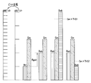
- FIG. 8 is a graph showing an example of the R signal Rwb, the G signal Gm, and the B signal Bwb when white balance correction is performed without performing level correction, together with the state of bit expansion.
- FIG. 8 shows an example where Rwb ⁇ Gm is satisfied.
- Step S15 it is determined whether or not Rfwb> Gm is satisfied.
- the conditions that all of Step S11, Step S13, and Step S15 are satisfied that is, Rm ⁇ Gm and Rwb ⁇ Gm and Rfwb> Gm
- the condition that is satisfied is the first condition.
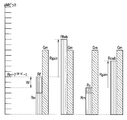
- FIG. 9 is a graph showing an example when white balance correction is performed on the R signal level correction maximum value Rf and the level-corrected R signal Rc. 8 and 9 show an example in which the first condition is satisfied.
- Rfwb> Gm when it is determined that Rfwb> Gm is satisfied, Rwb obtained by performing white balance correction on Rm remains less than Gm (see FIG. 8), but the maximum level correction is applied to Rm.
- Rfwb after white balance correction is larger than Gm (see FIG. 9), that is, the magnitude relationship between Rm and Gm after white balance correction can be reversed by level correction (accordingly) , Rm and Gm are originally not so different values).
- the saturation Sb related to B is calculated as follows (step) S16).
- FIG. 8 illustrates an example in which Sb> ThS1 (that is, Bwb> ⁇ Gm ⁇ ThS1 ⁇ ) is satisfied and an example in which Sb ⁇ ThS2 (that is, Bwb ⁇ Gm ⁇ ThS2 ⁇ ) is satisfied. Show.
- Rc is the range described above, Rm ⁇ Rc ⁇ Rm + W
- the specific value can be set as desired, but specific values include an example in which the central value in the range is Rc.
- step S18 If the process in step S18 is performed or if any of the conditions in steps S11, S13, S15, and S17 is not satisfied, the process returns to the process shown in FIG.
- the R signal Rc that has been level-corrected by multiplying the R signal Rc that has been level-corrected by the process of step S5 is the R signal that has been subjected to level correction and then subjected to white balance correction.
- Rcwb is calculated as shown in FIG.
- Rgain is multiplied by the R signal Rm in the white balance correction, and Rwb is calculated.
- FIG. 5 is a flowchart showing Bm level correction.
- the level correction unit 24 executes the Bm level correction process shown in FIG.
- the Bm level correction process shown in FIG. 5 is substantially the same as the Rm level correction process shown in FIG. 4 described above except that the signal to be processed is changed from the R signal to the B signal.
- step S21 when entering the process of FIG. 5, it is first determined whether or not Bm ⁇ Gm is satisfied.
- the B signal Bwb when white balance correction is performed without performing level correction by multiplying Bm by the white balance gain Bgain for the B signal Is calculated as follows (step S22).
- Bwb Bm ⁇ Bgain Then, it is determined whether or not Bwb ⁇ Gm is satisfied (step S23).
- Bm ⁇ Bc ⁇ Bm + W defined by the level correction width W described above. In this range, the B signal level is corrected, and the B signal Bc after the level correction is calculated.
- step S25 it is determined whether or not Bfwb> Gm is satisfied.
- the conditions that all of step S21, step S23, and step S25 are satisfied that is, Bm ⁇ Gm and Bwb ⁇ Gm and Bfwb> Gm
- the condition that is satisfied is the second condition.
- Bfwb> Gm Bwb obtained by performing white balance correction on Bm is still less than Gm, but the white balance is applied after performing maximum level correction on Bm.
- the corrected Bfwb becomes larger than Gm, that is, the magnitude relationship between Bm and Gm after white balance correction can be reversed by level correction (therefore, Bm and Gm are originally much less It is not a far off value).
- the saturation Sr related to R is calculated as follows (step) S26).
- step S28 is performed, or when any of the conditions of step S21, step S23, step S25, and step S27 is not satisfied, the process returns to the process shown in FIG.
- the B signal is obtained by multiplying the B signal Bc level-corrected by Bgain by the process of step S5 and performing white balance correction after level correction. Bcwb is calculated.
- Bgain is multiplied by the B signal Bm, and Bwb is calculated.
- the level correction unit 24 performs the R signal Rwb when white balance correction is performed without performing level correction.
- the saturation is calculated for each pixel based on the G signal Gm and the B signal Bwb, and it is further determined whether or not the third condition that the saturation is higher than a predetermined threshold is satisfied.
- Rc is calculated only when the above condition is satisfied, and Bc is calculated only when the second condition and the third condition are satisfied.
- the level correction unit 24 determines whether or not the third condition related to the calculation of Rc satisfies the third condition, that the saturation related to B is higher than the first threshold value or the saturation related to the complementary color of B. It is determined whether or not the degree is higher than the second threshold, and as a determination whether or not the third condition relating to the calculation of Bc is satisfied, the saturation according to R is higher than the third threshold Or whether or not the saturation related to the R complementary color is higher than the fourth threshold value is determined.
- FIG. 6 is a flowchart showing a modification of the Rm level correction
- FIG. 7 is a flowchart showing a modification of the Bm level correction.
- the process shown in FIG. 6 is obtained by omitting the processes in steps S16 and S17 from the process shown in FIG. 4, and the process shown in FIG. 7 is obtained by omitting the processes in steps S26 and S27 from the process shown in FIG. It has become. In this way, the determination as to whether or not the third condition regarding saturation is satisfied may be omitted.
- the levels correction unit 24 determines that the pixel has the first condition Rm ⁇ Gm and Rwb ⁇ Gm and Rfwb> Gm described above. Rc is calculated only when the first condition is satisfied, and the pixel further satisfies the second condition Bm ⁇ Gm and Bwb ⁇ Gm and Bfwb> Gm. Whether or not is satisfied and Bc is calculated only when the second condition is satisfied.
- the color video signal is the R signal, the G signal, and the B signal has been described.
- the present invention is not limited to this.
- the color video signal may be a complementary color signal or four colors. It may be a color video signal composed of the above signals.
- the saturation calculated by other methods may be used. Of course.
- the color balance of the color video signal expanded from N bits to M bits is subjected to level correction based on the bit number difference (MN) at the time of bit expansion, and then white balance correction is performed.
- MN bit number difference
- W [ ⁇ 2 ⁇ (MN) ⁇ -1]
- the level correction is performed on the color video signal in the range of Lm ⁇ Lc ⁇ Lm + W, the level suitable for the bit extension by multiplying the signal value by the value ⁇ 2 ⁇ (MN) ⁇ . Correction can be performed.
- the color video signal is an R signal, a G signal, and a B signal, and only the R signal and the B signal are subjected to level correction and white balance correction, the signal of the G signal that is a luminance equivalent signal.
- the value does not change between level correction and white balance correction, that is, there is an advantage that white balance correction can be performed while reducing false colors without substantially changing the brightness of the image.
- the pixel has the following first condition Rm ⁇ Gm and Rwb ⁇ Gm and Rfwb> Gm Since Rc is calculated only when the condition is satisfied, the false color component generated in the R signal by bit expansion can be reduced satisfactorily.
- the pixel has the following second condition Bm ⁇ Gm and Bwb ⁇ Gm and Bfwb> Gm Since Bc is calculated only when the condition is satisfied, the false color component generated in the B signal due to the bit expansion can be satisfactorily reduced.
- step S6 of FIG. 3 when a process for reducing the false color generated in the achromatic portion is separately performed, the efficiency of the process can be improved.
- the saturation related to B is higher than the first threshold, or the saturation related to the complementary color of B is higher than the second threshold. Therefore, it is possible to effectively reduce the conspicuous false color of the type in which the false color of R is mixed into B or the complementary color of B.
- the saturation related to R is higher than the third threshold, or the saturation related to the complementary color of R is higher than the fourth threshold. Since it is determined whether or not the high color is satisfied, the conspicuous false color of the type in which the false color of B is mixed with R or the complementary color of R can be effectively reduced.
- each part mentioned above may be comprised as a circuit. Any circuit may be mounted as a single circuit or a combination of a plurality of circuits as long as it can perform the same function. Furthermore, an arbitrary circuit is not limited to being configured as a dedicated circuit for performing a target function, and may be configured to perform a target function by causing a general-purpose circuit to execute a processing program. . Alternatively, a processor configured as hardware may perform processing of each unit.
- an image processing method for performing the same processing as the image processing apparatus may be used, and an image processing program for causing a computer to perform the same processing as the image processing apparatus ( A computer program), a non-temporary recording medium that can be read by a computer that records the image processing program, and the like.
- the present invention is not limited to the above-described embodiment as it is, and can be embodied by modifying the constituent elements without departing from the scope of the invention in the implementation stage.
- various aspects of the invention can be formed by appropriately combining a plurality of components disclosed in the embodiment. For example, some components may be deleted from all the components shown in the embodiment.
- constituent elements over different embodiments may be appropriately combined.
Landscapes
- Engineering & Computer Science (AREA)
- Multimedia (AREA)
- Signal Processing (AREA)
- Processing Of Color Television Signals (AREA)
- Color Television Image Signal Generators (AREA)
Abstract
カラー映像信号をNビットからM(M>N)ビットへ拡張するビット拡張部(23)と、Mビットに拡張されたカラー映像信号に(M-N)に基づくレベル補正を行うレベル補正部(24)と、レベル補正が行われたカラー映像信号にホワイトバランス補正を行うホワイトバランス補正部(25)と、を備える画像処理装置(1)。
Description
本発明は、カラー映像信号にホワイトバランス補正を行う画像処理装置、画像処理方法、記録媒体に関する。
アナログ信号は信号値が連続的に変化し得るのに対して、デジタル信号は所定の量子化単位で変化する。このために、アナログの画像信号をデジタル化して得られたRAW画像データには量子化誤差が含まれている。
こうしたRAW画像データに対して行われる画像処理には、一般的に、色信号毎に異なるホワイトバランスゲインを乗算するホワイトバランス補正の処理が含まれている。しかし、量子化誤差が含まれているRAW画像データにホワイトバランスゲインを乗算すると、色信号毎に拡大される誤差の大きさが異なるために、色信号間のカラーバランスがずれた偽色となって顕在化することがある。
こうした偽色は、無彩色部分において特に目立ってしまう。そこで、例えば日本国特開2015-207825号公報には、無彩色部分の偽色を低減する技術が記載されている。
ところで、近年の撮像装置には、撮像駆動モードとして、撮像データを高速で読み出すことができる高速読み出しモードを備えたものがあり、例えば高速連写撮影を行う場合、あるいは動きが滑らかな高速フレームレートの動画撮影を行う場合などに利用されている。このような高速読み出しモードは、通常読み出しモードよりも、A/D変換におけるビット数を低く抑えることで、読出時間の短縮を図った読み出しモードである。
上述したような量子化誤差を色信号毎に異なるゲインで拡大することにより生じる偽色は、無彩色部分だけでなく、有彩色部分にも発生する。しかしながら、上記日本国特開2015-207825号公報に記載の技術では、こうした有彩色部分に生じる偽色の低減については言及されていない。
無彩色部分に生じる偽色は、有彩色部分に生じる偽色に比べて顕在化し易い。ただし、有彩色部分であっても、注目画素に生じている偽色が、注目画素の周辺画素の色に対して補色である場合には、視覚的に認識されて顕在化することがある。あるいは、補色でなくても、注目画素に生じている偽色が、注目画素の周辺画素の色に対して色相を乖離させる偽色である場合には、同様に視覚的に認識されて顕在化することがある。
このとき、上述した高速読み出しモードで読み出された画像データは、通常読み出しモードで読み出された画像データと同じビット数にビット拡張してから画像処理等が行われるが、ビット拡張を行うと量子化誤差も拡大してしまうことになり、量子化誤差に起因する偽色がより目立つことになる。
本発明は上記事情に鑑みてなされたものであり、ビット拡張されたカラー映像信号の有彩色部分に生じる偽色を簡便かつ有効に低減することができる画像処理装置、画像処理方法、記録媒体を提供することを目的としている。
本発明の一態様による画像処理装置は、カラー映像信号を処理するための画像処理装置であって、ホワイトバランス補正を行う前のNビットのカラー映像信号を、M>Nを満たすMビットのカラー映像信号に拡張するビット拡張部と、前記ビット拡張部によりMビットに拡張された前記カラー映像信号に、(M-N)に基づくレベル補正を行うレベル補正部と、前記レベル補正部により前記レベル補正が行われた前記カラー映像信号に対して前記ホワイトバランス補正を行うホワイトバランス補正部と、を備える。
本発明の他の態様による画像処理方法は、カラー映像信号を処理するための画像処理方法であって、ホワイトバランス補正を行う前のNビットのカラー映像信号を、M>Nを満たすMビットのカラー映像信号に拡張するビット拡張ステップと、前記ビット拡張ステップによりMビットに拡張された前記カラー映像信号に、(M-N)に基づくレベル補正を行うレベル補正ステップと、前記レベル補正ステップにより前記レベル補正が行われた前記カラー映像信号に対して前記ホワイトバランス補正を行うホワイトバランス補正ステップと、を備える。
本発明のさらに他の態様による記録媒体は、画像処理装置のコンピュータに、カラー映像信号を処理させるための画像処理プログラムを記録したコンピュータで読取のできる記録媒体であって、前記画像処理プログラムは以下を含む、ホワイトバランス補正を行う前のNビットのカラー映像信号を、M>Nを満たすMビットのカラー映像信号に拡張するビット拡張ステップと、前記ビット拡張ステップによりMビットに拡張された前記カラー映像信号に、(M-N)に基づくレベル補正を行うレベル補正ステップと、前記レベル補正ステップにより前記レベル補正が行われた前記カラー映像信号に対して前記ホワイトバランス補正を行うホワイトバランス補正ステップ。
以下、図面を参照して本発明の実施の形態を説明する。
[実施形態1]
図1から図9は本発明の実施形態1を示したものであり、図1は画像処理装置1の構成を示すブロック図である。
図1から図9は本発明の実施形態1を示したものであり、図1は画像処理装置1の構成を示すブロック図である。
図1に示すように、この画像処理装置1は、デジタルのカラー映像信号(以下では単に、カラー映像信号あるいは画像データなどという)を処理するためのものであり、記録媒体10と、メモリインタフェース(メモリI/F)11と、バス12と、SDRAM13と、画像処理部14と、JPEG処理部15と、動画コーデック16と、操作部17と、フラッシュメモリ18と、マイクロコンピュータ19と、を備えている。
記録媒体10は、例えば画像処理装置1に着脱できるメモリカード等により構成されていて、画像データ(動画像データ、静止画像データ等)を不揮発に記憶する記録部である。従って、記録媒体10は、画像処理装置1に固有の構成である必要はない。
なお、本実施形態においては、画像処理装置1が、例えば記録媒体10を介して画像データを入力するものとして説明するが、これに限定されるものではなく、通信回線等を介して画像データを入力する構成であっても構わないし、画像処理装置1が撮像装置に組み込まれたものである場合には、撮像装置で撮像して取得された画像データを処理する構成としても良い。
そして、画像データは、レンズにより結像された被写体の光学像を、例えば、原色ベイヤー配列のカラーフィルタを備えたカラー撮像素子により光電変換し、さらにA/D変換して得られたデジタルのカラー画像信号、つまりいわゆるRAW画像データであるものとする。
このとき、撮像素子は、例えば、通常読み出しモードと、高速読み出しモードと、で動作することができるようになっている。ここに、通常読み出しモードは、例えば静止画撮影を行う場合などに用いられる。また、高速読み出しモードは、例えば高速連写撮影を行う場合、あるいは動きが滑らかな高速フレームレートの動画撮影を行う場合などに用いられる。そして、高速読み出しモードは、通常読み出しモードよりも、A/D変換におけるビット数を低く抑えることで、読出時間の短縮を図った読み出しモードである。すなわち、通常読み出し時には例えばMビットA/D変換が行われ、高速読み出し時にはNビットA/D変換が行われるようになっている。ここに、M,Nは、M>Nを満たす正の整数である。具体的な数値の一例を挙げれば、M=10、N=8である。
メモリI/F11は、記録媒体10に記録されている画像データを読み出す制御を行う読出制御部であり、さらに、画像処理後の画像データを記録媒体10へ記録する制御を行う記録制御部でもある。
バス12は、各種のデータや制御信号を、画像処理装置1内のある場所から他の場所へ転送するための転送路である。本実施形態におけるバス12は、メモリI/F11と、SDRAM13と、画像処理部14と、JPEG処理部15と、動画コーデック16と、マイクロコンピュータ19と、に接続されている。
そして、メモリI/F11により記録媒体10から読み出された画像データは、バス12を介して転送され、SDRAM13に一旦記憶される。
SDRAM13は、記録媒体10から読み出された画像データ、画像処理部14により処理されもしくは処理途中の画像データ、動画コーデック16により処理されもしくは処理途中の画像データ、等の各種データを一時的に記憶する記憶部である。
画像処理部14は、画像データに各種の画像処理を行い、表示用あるいは記録用の画像を作成する。
JPEG処理部15は、静止画像データを、JPEG処理により圧縮または伸張する圧縮伸張部である。このJPEG処理部15により処理された静止画像データは、マイクロコンピュータ19によりヘッダ等を付加されて、メモリI/F11を介して記録媒体10にJPEGファイルとして記録される。
動画コーデック16は、動画像データを、MotionJPEGやMPEGなどの適宜の処理方式で圧縮伸張するものである。この動画コーデック16により処理された動画像データは、マイクロコンピュータ19によりヘッダ等を付加されて、メモリI/F11を介して記録媒体10に動画像ファイルとして記録される。
操作部17は、この画像処理装置1に対する各種の操作入力を行うためのものであり、画像処理装置1の電源のオン/オフ、画像処理の開始/終了、画像処理における各種パラメータの設定、記録媒体10に対する画像ファイルの読み出しや保存などを操作することができるようになっている。この操作部17に対して操作が行われると、操作内容に応じた信号がマイクロコンピュータ19へ出力される。
フラッシュメモリ18は、マイクロコンピュータ19により実行される処理プログラム(画像処理装置1により画像処理方法を実行するためのプログラムである画像処理プログラムを含む)と、この画像処理装置1に係る各種の情報と、を不揮発に記憶する記憶媒体である。ここに、フラッシュメモリ18が記憶する情報としては、例えば、画像処理に用いるパラメータ、テーブル、関数、あるいはユーザにより設定された設定値などが挙げられる。具体的に、フラッシュメモリ18には、光源の種類(例えば、昼間太陽、朝夕太陽、電球、蛍光灯など)に応じたホワイトバランスゲインが記憶されている。このフラッシュメモリ18が記憶する情報は、マイクロコンピュータ19により読み取られる。
マイクロコンピュータ19は、画像処理装置1を統括的に制御する制御部である。マイクロコンピュータ19は、操作部17からユーザの操作入力を受けると、フラッシュメモリ18に記憶されている処理プログラムに従って、フラッシュメモリ18から処理に必要なパラメータ等を読み込んで、操作内容に応じた各種のシーケンスを実行する。
例えば、対象となる画像が選択されて、画像処理の実行が開始されると、マイクロコンピュータ19の制御に基づいて、記録媒体10からメモリI/F11を介して画像データが読み出され、バス12を介してSDRAM13に記憶される。さらに、マイクロコンピュータ19の制御に基づいて、画像処理部14により画像処理が行われ、画像処理後の画像データが再びSDRAM13に記憶される。この画像処理後の画像データは例えばモニタなどの表示部に表示される。ユーザは、モニタに表示された画像を見て、必要に応じて処理パラメータの設定値を変更して、画像処理を再度実行することもできる。そして、画像データが静止画像データである場合にはJPEG処理部15によりJPEG圧縮され、また、画像データが動画像データである場合には動画コーデック16により動画圧縮されて、画像ファイルとして記録媒体10に記録される。
なお、画像処理装置1は、専用の処理装置として構成されていても良いし、コンピュータに画像処理プログラムを実行させる構成であっても構わない。あるいは、画像処理装置1は、撮像装置内に組み込まれたものであっても構わない。
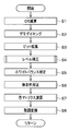
次に、図2は画像処理部14の構成を示すブロック図、図3は画像処理部14の作用を示すフローチャートである。
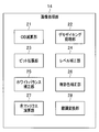
図2に示すように、画像処理部14は、OB減算部21と、デモザイキング処理部22と、ビット拡張部23と、レベル補正部24と、ホワイトバランス補正部25と、無彩色補正部26と、色マトリクス演算部27と、階調変換部28と、を備えている。
そして、画像処理装置1における図示しないメイン処理から図3に示す処理に入ると、OB減算部21は、画像データにOB(オプティカル・ブラック)成分が含まれている場合に、OB成分の減算を行う(ステップS1)。従って、OB成分が含まれている画像データの場合には、記録媒体10にOB成分も記録されていてメモリI/F11により読み出されることになる。
デモザイキング処理部22は、デモザイキング処理を行う(ステップS2)。すなわち、デモザイキング処理部22は、1画素に付き1色の色信号のみが存在するRGBベイヤー画像において、ある色信号が欠落する画素の該色信号を、該画素の近傍において同色の色信号を有する画素の色信号に基づき補間することを、各画素の各欠落色信号に対して行うことにより、1画素に付きRGB各色の色信号が存在する画像を生成する。
ビット拡張部23は、ホワイトバランス補正を行う前のNビットのカラー映像信号を、M>Nを満たすMビットのカラー映像信号に拡張する(ステップS3)。従って、ビット拡張部23は、画像データのビット数がMビットである場合には、特段の処理は行わない。
ここで、画像処理部14において、ビット拡張部23よりも前段に配置されている各部、具体的に図3に示す処理順序の場合には、OB減算部21およびデモザイキング処理部22は、入力された画像データがNビットでもMビットでも、何れも処理することができるように構成されている。
これに対して、画像処理部14において、ビット拡張部23よりも後段に配置されている各部、具体的に図3に示す処理順序の場合には、レベル補正部24と、ホワイトバランス補正部25と、無彩色補正部26と、色マトリクス演算部27と、階調変換部28とは、Mビットの画像データを処理するように構成されている。
従って、ビット拡張部23は、入力された画像データのビット数がMビット未満(具体的には、Nビット)である場合に、後段の処理ビットに合わせてMビットへのビット拡張を行うものとなっている。
なお、上述では、画像処理部に入力される画像データのビット数がMビットまたはNビットになる理由の例として、撮像素子の読出モードが通常読み出しモードまたは高速読み出しモードである例を説明したが、この例に限定されるものではない。例えば、複数の画像データが異なる撮像装置で取得されたこと、つまり、第1の画像データはMビットの画像データを出力する第1の撮像装置により取得され、第2の画像データはNビットの画像データを出力する第2の撮像装置により取得されたことが理由であっても構わない。
レベル補正部24は、ビット拡張部23によりMビットに拡張されたカラー映像信号に、(M-N)に基づくレベル補正を行う(ステップS4)。レベル補正部24は、べき乗を記号「^」により表す(以下、同様)とすると、レベル補正幅Wを、例えば、
W={2^(M-N)}-1
により算出し、レベル補正幅Wにより規定される範囲(すなわち、ビット拡張により生じる量子化誤差の範囲)でカラー映像信号にレベル補正を行う。
W={2^(M-N)}-1
により算出し、レベル補正幅Wにより規定される範囲(すなわち、ビット拡張により生じる量子化誤差の範囲)でカラー映像信号にレベル補正を行う。
より具体的に、レベル補正部24は、レベル補正を行う前のカラー映像信号をLm、レベル補正を行った後のカラー映像信号をLcとすると、
Lm<Lc≦Lm+W
の範囲でカラー映像信号にレベル補正を行う。カラー映像信号の信号値に値{2^(M-N)}を乗算することによりビット拡張を行う場合には、この補正範囲が適切である。
Lm<Lc≦Lm+W
の範囲でカラー映像信号にレベル補正を行う。カラー映像信号の信号値に値{2^(M-N)}を乗算することによりビット拡張を行う場合には、この補正範囲が適切である。
ただし、その他の何らかの方法でビット数が(M-N)だけ増加するビット拡張を行う場合には、この補正範囲に限定されるものではなく、例えば、
{Lm-(W/2)}<Lc≦{Lm+(W/2)}
の範囲、あるいは、
(Lm-W)<Lc≦Lm
の範囲など(これらの場合でも、レベル補正幅Wにより規定される範囲は維持される)でカラー映像信号にレベル補正を行う、等であっても構わない。
{Lm-(W/2)}<Lc≦{Lm+(W/2)}
の範囲、あるいは、
(Lm-W)<Lc≦Lm
の範囲など(これらの場合でも、レベル補正幅Wにより規定される範囲は維持される)でカラー映像信号にレベル補正を行う、等であっても構わない。
本実施形態においては、カラー映像信号が、R信号、G信号、およびB信号である場合を想定しており、後述するように、レベル補正部24は、G信号にレベル補正を行わず、R信号およびB信号にレベル補正を行うようにしている。これは、G信号が輝度相当信号であるために、レベル補正によりカラーバランスは変化させるが、輝度は変化させないようにするためである。
ホワイトバランス補正部25は、レベル補正部24によりレベル補正が行われたカラー映像信号に対してホワイトバランス補正を行う(ステップS5)。このホワイトバランス補正は、白色の被写体が画像上においても白色に見えるようにするためのカラーバランス補正である。
ここに、上述したように、G信号は輝度相当信号であるために、ホワイトバランス補正によりホワイトバランスは変化させるが、輝度は変化させないようにすることが好ましい。そこで、ホワイトバランス補正部25は、ホワイトバランス補正による信号値変化を、G信号に生じさせず(ゲインを乗算しないか、あるいは乗算するゲインを1とする)、R信号およびB信号に生じさせ得る(R信号にはR信号に対するホワイトバランスゲインRgainを乗算し、B信号にはB信号に対するホワイトバランスゲインBgainを乗算する)。
ここに、上述したような光源の種類に応じたホワイトバランスゲインは、マイクロコンピュータ19によりフラッシュメモリ18から読み出されて、レベル補正部24とホワイトバランス補正部25とへ送信されるようになっている。一方、ホワイトバランス補正部25が画像データに基づき適応的にホワイトバランスゲインを決定する場合には、ホワイトバランス補正部25により決定されたホワイトバランスゲインが、ホワイトバランス補正部25によるホワイトバランス補正が行われる前に、ホワイトバランス補正部25からレベル補正部24へ送信される。こうして何れにおいてもレベル補正部24は、ホワイトバランス補正部25によるホワイトバランス補正が行われる前に、ホワイトバランスゲインを取得するようになっている。
無彩色補正部26は、画像の無彩色部分に生じる偽色の低減処理を、例えば上述した日本国特開2015-207825号公報に記載の技術に基づき行う(ステップS6)。すなわち、本実施形態においては、画像の有彩色部分(ただし、後述するように有彩色部分に限定されるものではない)に生じる偽色をレベル補正部24の処理により低減し、画像の無彩色部分に生じる偽色を無彩色補正部26の処理により低減するようになっている。
色マトリクス演算部27は、画像データを構成する各画素データのRGB信号を例えば3行1列(あるいは1行3列でも構わない)の行列として構成し、この画素データに3行3列の色マトリクスを行列演算して、色空間を変換する処理を行う(ステップS7)。ここに、3行3列の色マトリクスを構成する色マトリクス係数は、例えば、フラッシュメモリ18に予め記録されている。
階調変換部28は、モニタでの階調表示が適切となるような階調変換特性(例えば、ガンマ変換特性など)で画像を階調変換する(ステップS8)。
その後は、画像処理装置1の図示しないメイン処理にリターンする。
なお、図3に示した画像処理部14内における処理順序は一例であるので、ステップS3のビット拡張を行い、その後にステップS4のレベル補正を行い、その後にステップS5のホワイトバランス補正を行うという順序が維持される点を除き、合理的な範囲内においてその他の処理順序で処理しても構わない。
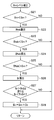
次に、図4は、Rmレベル補正を示すフローチャートである。図3のステップS4においてレベル補正の処理に入ると、レベル補正部24は、R信号に関してこの図4に示すRmレベル補正の処理を画素毎に実行し、B信号に関して後述する図5に示すBmレベル補正の処理を画素毎に実行するようになっている。
ここに、Rm,Bmは、レベル補正を行う前のR,B信号をそれぞれ表している。また、以下においては、レベル補正を行った後のR,B信号をそれぞれRc,Bcとして表すものとする。
図4の処理に入ると、まず、Rm<Gmが満たされているか否かを判定する(ステップS11)。
ここで、Rm<Gmが満たされていると判定された場合には、R信号に対するホワイトバランスゲインRgainをRmに乗算して、レベル補正を行うことなくホワイトバランス補正を行った場合のR信号Rwbを、次のように算出する(ステップS12)。
Rwb=Rm×Rgain
そして、Rwb<Gmが満たされているか否かを判定する(ステップS13)。
そして、Rwb<Gmが満たされているか否かを判定する(ステップS13)。
ここで、図8は、レベル補正を行うことなくホワイトバランス補正を行った場合のR信号Rwb、G信号Gm、およびB信号Bwbの例を、ビット拡張の様子と共に示すグラフである。この図8は、Rwb<Gmが満たされている例を示している。
ここで、Rwb<Gmが満たされていると判定された場合には、レベル補正幅Wを、
W={2^(M-N)}-1
により算出する。レベル補正を行った後のR信号をRcとすると、レベル補正幅Wにより規定される
Rm<Rc≦Rm+W
の範囲でR信号のレベル補正が行われるようになっている。
W={2^(M-N)}-1
により算出する。レベル補正を行った後のR信号をRcとすると、レベル補正幅Wにより規定される
Rm<Rc≦Rm+W
の範囲でR信号のレベル補正が行われるようになっている。
そこで、R信号のレベル補正最大値Rfを、
Rf=Rm+W
として算出し、さらに、R信号に対するホワイトバランスゲインRgainをRfに乗算して、最大のレベル補正を行った場合のR信号Rfwbを、次のように算出する(ステップS14)。
Rf=Rm+W
として算出し、さらに、R信号に対するホワイトバランスゲインRgainをRfに乗算して、最大のレベル補正を行った場合のR信号Rfwbを、次のように算出する(ステップS14)。
Rfwb=Rf×Rgain
次に、Rfwb>Gmが満たされているか否かを判定する(ステップS15)。ここに、ステップS11、ステップS13、およびステップS15が全て満たされる条件、つまり、
Rm<GmかつRwb<GmかつRfwb>Gm
が満たされる条件は、第1の条件である。
次に、Rfwb>Gmが満たされているか否かを判定する(ステップS15)。ここに、ステップS11、ステップS13、およびステップS15が全て満たされる条件、つまり、
Rm<GmかつRwb<GmかつRfwb>Gm
が満たされる条件は、第1の条件である。
図9は、R信号のレベル補正最大値Rfとレベル補正を行ったR信号Rcとにホワイトバランス補正を行ったときの例を示すグラフである。図8および図9には、第1の条件が満たされる例を示している。
ここで、Rfwb>Gmが満たされていると判定された場合には、Rmにそのままホワイトバランス補正を行ったRwbはGm未満のままである(図8参照)が、Rmに最大のレベル補正を行ってからホワイトバランス補正を行ったRfwbはGmよりも大きくなる(図9参照)ことを意味し、つまり、レベル補正によってホワイトバランス補正後のRmとGmとの大小関係が逆転し得ること(従って、RmとGmとは、元々、それほどかけ離れた値ではないこと)を意味している。
この図4に示す処理においては、Rfwb>Gmが満たされていると判定された場合に、さらに、処理対象の画素が、有彩色であるか否かを判定するようになっている。
すなわち、まず、Rmのレベル補正に関連して、有彩色であるか否かを示す指標(広い意味での彩度)として、例えば、Bに係る彩度Sbを次のように算出する(ステップS16)。
Sb=Bwb/Gm
そして、Bに係る彩度が第1の閾値よりも高いことの判定として、Sb>ThS1(ここに、ThS1>1.0を満たす)であるか否かを判定し、Bの補色に係る彩度が第2の閾値よりも高いことの判定として、Sb<ThS2(ここに、ThS2<1.0を満たす)であるか否かを判定する(ステップS17)。
そして、Bに係る彩度が第1の閾値よりも高いことの判定として、Sb>ThS1(ここに、ThS1>1.0を満たす)であるか否かを判定し、Bの補色に係る彩度が第2の閾値よりも高いことの判定として、Sb<ThS2(ここに、ThS2<1.0を満たす)であるか否かを判定する(ステップS17)。
図8には、Sb>ThS1(すなわち、Bwb>{Gm×ThS1})が満たされる場合の例と、Sb<ThS2(すなわち、Bwb<{Gm×ThS2})が満たされる場合の例と、を示している。
ここで、Sb>ThS1とSb<ThS2との何れか一方が満たされると判定された場合には、
0<Cr≦W
の範囲において、レベル補正量Crを設定し、
Rc=Rm+Cr
により、レベル補正を行った後のR信号Rcを算出する(ステップS18)。
0<Cr≦W
の範囲において、レベル補正量Crを設定し、
Rc=Rm+Cr
により、レベル補正を行った後のR信号Rcを算出する(ステップS18)。
こうして、Rcは、上述した範囲、
Rm<Rc≦Rm+W
において所望に設定することができるが、具体的な値としては、範囲内における中央の値をRcとする一例が挙げられる。
Rm<Rc≦Rm+W
において所望に設定することができるが、具体的な値としては、範囲内における中央の値をRcとする一例が挙げられる。
ただし、Wは、(M-N)=1,2,3,4,…に応じて、W=1,3,7,15…等の奇数値をとるために、Wの半分の値は半奇数となる。そこで、中央値に隣接する整数値の一方、
Rc=Rm+[{2^(M-N)}-1+1]/2
=Rm+{2^(M-N-1)}
をより具体的な例として挙げておく。
Rc=Rm+[{2^(M-N)}-1+1]/2
=Rm+{2^(M-N-1)}
をより具体的な例として挙げておく。
この例の場合には、ビット拡張したときのビット数の変化(M-N)=1,2,3,4,…に応じて、
Rc=(Rm+1),(Rm+2),(Rm+4),(Rm+8),…
のレベル補正を行うことになる。
Rc=(Rm+1),(Rm+2),(Rm+4),(Rm+8),…
のレベル補正を行うことになる。
このステップS18の処理を行うか、またはステップS11、ステップS13、ステップS15、ステップS17の何れかの条件が満たされない場合には、図3に示す処理にリターンする。
ステップS18の処理を行った場合には、その後のステップS5の処理により、レベル補正されたR信号Rcに対してRgainが乗算され、レベル補正を行ってからホワイトバランス補正を行ったR信号であるRcwbが図9に示すように算出されることになる。一方、ステップS18の処理を行わなかった場合には、ホワイトバランス補正において、R信号Rmに対してRgainが乗算され、Rwbが算出されることになる。
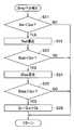
次に、図5は、Bmレベル補正を示すフローチャートである。上述したように、図3のステップS4においてレベル補正の処理に入ると、レベル補正部24は、B信号について、この図5に示すBmレベル補正の処理を画素毎に実行する。この図5に示すBmレベル補正の処理は、処理対象の信号がR信号からB信号になる以外は、上述した図4に示すRmレベル補正の処理とほぼ同様である。
すなわち、図5の処理に入ると、まず、Bm<Gmが満たされているか否かを判定する(ステップS21)。
ここで、Bm<Gmが満たされていると判定された場合には、B信号に対するホワイトバランスゲインBgainをBmに乗算して、レベル補正を行うことなくホワイトバランス補正を行った場合のB信号Bwbを、次のように算出する(ステップS22)。
Bwb=Bm×Bgain
そして、Bwb<Gmが満たされているか否かを判定する(ステップS23)。
そして、Bwb<Gmが満たされているか否かを判定する(ステップS23)。
ここで、Bwb<Gmが満たされていると判定された場合には、上述したレベル補正幅Wにより規定される
Bm<Bc≦Bm+W
の範囲でB信号のレベル補正が行われ、レベル補正を行った後のB信号Bcが算出されるようになっている。
Bm<Bc≦Bm+W
の範囲でB信号のレベル補正が行われ、レベル補正を行った後のB信号Bcが算出されるようになっている。
そこで、B信号のレベル補正最大値Bfを、
Bf=Bm+W
として算出し、さらに、B信号に対するホワイトバランスゲインBgainをBfに乗算して、最大のレベル補正を行った場合のB信号Bfwbを、次のように算出する(ステップS24)。
Bf=Bm+W
として算出し、さらに、B信号に対するホワイトバランスゲインBgainをBfに乗算して、最大のレベル補正を行った場合のB信号Bfwbを、次のように算出する(ステップS24)。
Bfwb=Bf×Bgain
次に、Bfwb>Gmが満たされているか否かを判定する(ステップS25)。ここに、ステップS21、ステップS23、およびステップS25が全て満たされる条件、つまり、
Bm<GmかつBwb<GmかつBfwb>Gm
が満たされる条件は、第2の条件である。
次に、Bfwb>Gmが満たされているか否かを判定する(ステップS25)。ここに、ステップS21、ステップS23、およびステップS25が全て満たされる条件、つまり、
Bm<GmかつBwb<GmかつBfwb>Gm
が満たされる条件は、第2の条件である。
ここで、Bfwb>Gmが満たされていると判定された場合には、Bmにそのままホワイトバランス補正を行ったBwbはGm未満のままであるが、Bmに最大のレベル補正を行ってからホワイトバランス補正を行ったBfwbはGmよりも大きくなることを意味し、つまり、レベル補正によってホワイトバランス補正後のBmとGmとの大小関係が逆転し得ること(従って、BmとGmとは、元々、それほどかけ離れた値ではないこと)を意味している。
この図5に示す処理においては、Bfwb>Gmが満たされていると判定された場合に、さらに、処理対象の画素が、有彩色であるか否かを判定するようになっている。
すなわち、まず、Bmのレベル補正に関連して、有彩色であるか否かを示す指標(広い意味での彩度)として、例えば、Rに係る彩度Srを次のように算出する(ステップS26)。
Sr=Rwb/Gm
そして、Rに係る彩度が第3の閾値よりも高いことの判定として、Sr>ThS3(ここに、ThS3>1.0を満たす)であるか否かを判定し、Rの補色に係る彩度が第4の閾値よりも高いことの判定として、Sr<ThS4(ここに、ThS4<1.0を満たす)であるか否かを判定する(ステップS27)。
そして、Rに係る彩度が第3の閾値よりも高いことの判定として、Sr>ThS3(ここに、ThS3>1.0を満たす)であるか否かを判定し、Rの補色に係る彩度が第4の閾値よりも高いことの判定として、Sr<ThS4(ここに、ThS4<1.0を満たす)であるか否かを判定する(ステップS27)。
ここで、Sr>ThS3とSr<ThS4との何れか一方が満たされると判定された場合には、
0<Cb≦W
の範囲において、レベル補正量Cbを設定し、
Bc=Bm+Cb
により、レベル補正を行った後のB信号Bcを算出する(ステップS28)。
0<Cb≦W
の範囲において、レベル補正量Cbを設定し、
Bc=Bm+Cb
により、レベル補正を行った後のB信号Bcを算出する(ステップS28)。
ここに、Bcの具体的な値の一例としては、範囲内における中央の値に最も近い整数値、すなわち、
Bc=Bm+{2^(M-N-1)}
が挙げられるのは、上述したRcの場合と同様である。
Bc=Bm+{2^(M-N-1)}
が挙げられるのは、上述したRcの場合と同様である。
このステップS28の処理を行うか、またはステップS21、ステップS23、ステップS25、ステップS27の何れかの条件が満たされない場合には、図3に示す処理にリターンする。
ステップS28の処理を行った場合には、その後のステップS5の処理により、レベル補正されたB信号Bcに対してBgainが乗算され、レベル補正を行ってからホワイトバランス補正を行ったB信号であるBcwbが算出されることになる。一方、ステップS28の処理を行わなかった場合には、ホワイトバランス補正において、B信号Bmに対してBgainが乗算され、Bwbが算出されることになる。
こうして図4のステップS16およびステップS17と、図5のステップS26およびステップS27とにおいて説明したように、レベル補正部24は、レベル補正を行うことなくホワイトバランス補正を行った場合のR信号Rwb、G信号Gm、およびB信号Bwbに基づき彩度を画素毎に算出して、彩度が所定の閾値よりも高い第3の条件を満たすか否かをさらに判定し、第1の条件および第3の条件を満たす場合にのみRcを算出し、第2の条件および第3の条件を満たす場合にのみBcを算出している。
具体的に、レベル補正部24は、Rcの算出に係る第3の条件を満たすか否かの判定として、Bに係る彩度が第1の閾値よりも高いこと、またはBの補色に係る彩度が第2の閾値よりも高いことを満たすか否かを判定し、Bcの算出に係る第3の条件を満たすか否かの判定として、Rに係る彩度が第3の閾値よりも高いこと、またはRの補色に係る彩度が第4の閾値よりも高いことを満たすか否かを判定している。
なお、図4および図5に示した処理においては、上述したように彩度に関する第3の条件を満たすか否かを判定して(ステップS16~S17およびステップS26~S27等参照)、第3の条件が満たされる場合にのみ、レベル補正部24によるレベル補正を行うようにしていた。
しかし、これに限定されるものではない。
図6はRmレベル補正の変形例を示すフローチャート、図7はBmレベル補正の変形例を示すフローチャートである。
図6に示す処理は、図4に示す処理からステップS16およびステップS17の処理を省略したもの、図7に示す処理は、図5に示す処理からステップS26およびステップS27の処理を省略したものとなっている。このように、彩度に関する第3の条件を満たすか否かの判定を省略しても構わない。
図4および図5に示した処理と、図6および図7に示した処理と、の何れにおいても、ステップS11、ステップS13、およびステップS15の処理と、ステップS21、ステップS23、およびステップS25の処理と、は行われるために、レベル補正部24は、画素が、上述した第1の条件
Rm<GmかつRwb<GmかつRfwb>Gm
を満たすか否かを判定し、第1の条件を満たす場合にのみRcを算出し、さらに画素が、上述した第2の条件
Bm<GmかつBwb<GmかつBfwb>Gm
を満たすか否かを判定し、第2の条件を満たす場合にのみBcを算出していることになる。
Rm<GmかつRwb<GmかつRfwb>Gm
を満たすか否かを判定し、第1の条件を満たす場合にのみRcを算出し、さらに画素が、上述した第2の条件
Bm<GmかつBwb<GmかつBfwb>Gm
を満たすか否かを判定し、第2の条件を満たす場合にのみBcを算出していることになる。
なお、上述ではカラー映像信号が、R信号、G信号、およびB信号である場合を説明したが、これに限定されるものではなく、例えば、補色系の信号であっても良いし、4色以上の信号で構成されるカラー映像信号であっても構わない。
また、上述では、Rに係る彩度SrをSr=Rwb/Gmにより算出し、Bに係る彩度SbをSb=Bwb/Gmにより算出したが、その他の方法で算出した彩度を用いても勿論構わない。
このような実施形態1によれば、NビットからMビットに拡張されたカラー映像信号に、ビット拡張時のビット数の差(M-N)に基づくレベル補正を行ってからホワイトバランス補正を行うようにしたために、周辺画素の参照を不要としながら(つまり、負荷の重い複雑な処理を要することなく)、ビット拡張されたカラー映像信号の有彩色部分に生じる偽色を簡便かつ有効に低減することができる。
また、レベル補正幅W=[{2^(M-N)}-1]により規定される範囲(すなわち、ビット拡張により生じる量子化誤差の範囲)でカラー映像信号にレベル補正を行うようにしたために、過補正になることなく(つまり、副作用をほとんど生じさせることなく)、ビット拡張に起因する偽色を適切に補正することができる。
そして、Lm<Lc≦Lm+Wの範囲でカラー映像信号にレベル補正を行うようにしたために、信号値に値{2^(M-N)}を乗算することによりビット拡張を行う場合に適したレベル補正を行うことができる。
特に、上述ではカラー映像信号を、R信号、G信号、およびB信号として、R信号およびB信号のみにレベル補正とホワイトバランス補正とを行うようにしたために、輝度相当信号であるG信号の信号値はレベル補正とホワイトバランス補正とにおいて変化せず、つまり画像の明るさをほぼ変化させることなく、偽色を低減してホワイトバランス補正を行うことができる利点がある。
このとき、レベル補正幅Wにより規定される
Rm<Rc≦Rm+W
Bm<Bc≦Bm+W
の範囲でR,B信号にレベル補正を行うことで、量子化誤差の範囲に応じた適切なレベル補正をR,B信号に対して行うことができる。
Rm<Rc≦Rm+W
Bm<Bc≦Bm+W
の範囲でR,B信号にレベル補正を行うことで、量子化誤差の範囲に応じた適切なレベル補正をR,B信号に対して行うことができる。
そして、画素が、次の第1の条件
Rm<GmかつRwb<GmかつRfwb>Gm
を満たす場合にのみRcを算出するようにしたために、ビット拡張によりR信号に生じる偽色成分を良好に低減することができる。
Rm<GmかつRwb<GmかつRfwb>Gm
を満たす場合にのみRcを算出するようにしたために、ビット拡張によりR信号に生じる偽色成分を良好に低減することができる。
また、画素が、次の第2の条件
Bm<GmかつBwb<GmかつBfwb>Gm
を満たす場合にのみBcを算出するようにしたために、ビット拡張によりB信号に生じる偽色成分を良好に低減することができる。
Bm<GmかつBwb<GmかつBfwb>Gm
を満たす場合にのみBcを算出するようにしたために、ビット拡張によりB信号に生じる偽色成分を良好に低減することができる。
さらに、図6に示したように第1の条件を満たす場合にRcを算出し、図7に示したように第2の条件を満たす場合にBcを算出するようにすれば、無彩色付近の低彩度色に生じる偽色も有効に低減することができる。
一方、彩度が所定の閾値よりも高い第3の条件を満たすか否かをさらに判定して、第1の条件および第3の条件を満たす場合にのみRcを算出し、第2の条件および第3の条件を満たす場合にのみBcを算出する場合には、彩度が低い場合のレベル補正が不要となり、処理負荷を軽減することができる。特に、図3のステップS6に示したように、無彩色部分に生じる偽色の低減処理を別途行う場合には、処理の効率化を図ることができる。
このとき、Rcの算出に係る第3の条件を満たすか否かの判定として、Bに係る彩度が第1の閾値よりも高いこと、またはBの補色に係る彩度が第2の閾値よりも高いことを満たすか否かを判定するようにしたために、BまたはBの補色にRの偽色が混入するタイプの、目立つ偽色を効果的に低減することができる。
また、Bcの算出に係る第3の条件を満たすか否かの判定として、Rに係る彩度が第3の閾値よりも高いこと、またはRの補色に係る彩度が第4の閾値よりも高いことを満たすか否かを判定するようにしたために、RまたはRの補色にBの偽色が混入するタイプの、目立つ偽色を効果的に低減することができる。
なお、上述した各部は、回路として構成されていてもよい。そして、任意の回路は、同一の機能を果たすことができれば、単一の回路として実装されていてもよいし、複数の回路を組み合わせたものとして実装されていても構わない。さらに、任意の回路は、目的とする機能を果たすための専用回路として構成されるに限るものではなく、汎用回路に処理プログラムを実行させることで目的とする機能を果たす構成であっても構わない。あるいは、ハードウェアとして構成されたプロセッサが、各部の処理を行うようにしてもよい。
また、上述では主として画像処理装置について説明したが、画像処理装置と同様の処理を行う画像処理方法であってもよいし、コンピュータに画像処理装置と同様の処理を行わせるための画像処理プログラム(コンピュータプログラム)、該画像処理プログラムを記録するコンピュータにより読み取りできる一時的でない記録媒体、等であっても構わない。
さらに、本発明は上述した実施形態そのままに限定されるものではなく、実施段階ではその要旨を逸脱しない範囲で構成要素を変形して具体化することができる。また、上記実施形態に開示されている複数の構成要素の適宜な組み合わせにより、種々の発明の態様を形成することができる。例えば、実施形態に示される全構成要素から幾つかの構成要素を削除してもよい。さらに、異なる実施形態にわたる構成要素を適宜組み合わせてもよい。このように、発明の主旨を逸脱しない範囲内において種々の変形や応用をすることができるのは勿論である。
本出願は、2017年2月27日に日本国に出願された特願2017-34594号を優先権主張の基礎として出願するものであり、上記の開示内容は、本願明細書、請求の範囲、図面に引用されたものとする。
Claims (14)
- カラー映像信号を処理するための画像処理装置であって、
ホワイトバランス補正を行う前のNビットのカラー映像信号を、M>Nを満たすMビットのカラー映像信号に拡張するビット拡張部と、
前記ビット拡張部によりMビットに拡張された前記カラー映像信号に、(M-N)に基づくレベル補正を行うレベル補正部と、
前記レベル補正部により前記レベル補正が行われた前記カラー映像信号に対して前記ホワイトバランス補正を行うホワイトバランス補正部と、
を備えることを特徴とする画像処理装置。 - 前記レベル補正部は、べき乗を記号「^」により表すとすると、レベル補正幅Wを、
W={2^(M-N)}-1
により算出し、前記レベル補正幅Wにより規定される範囲で前記カラー映像信号に前記レベル補正を行うことを特徴とする請求項1に記載の画像処理装置。 - 前記レベル補正を行う前の前記カラー映像信号をLm、前記レベル補正を行った後の前記カラー映像信号をLcとすると、前記レベル補正部は、
Lm<Lc≦Lm+W
の範囲で前記カラー映像信号に前記レベル補正を行うことを特徴とする請求項2に記載の画像処理装置。 - 前記カラー映像信号は、R信号、G信号、およびB信号であり、
前記レベル補正部は、G信号に前記レベル補正を行わず、R信号およびB信号に前記レベル補正を行い、
前記ホワイトバランス補正部は、前記ホワイトバランス補正による信号値変化を、G信号に生じさせず、R信号およびB信号に生じさせ得ることを特徴とする請求項1に記載の画像処理装置。 - 前記レベル補正を行う前のR,B信号をRm,Bm、前記レベル補正を行った後のR,B信号をRc,Bcとし、べき乗を記号「^」により表すとすると、前記レベル補正部は、レベル補正幅Wを、
W={2^(M-N)}-1
により算出し、前記レベル補正幅Wにより規定される
Rm<Rc≦Rm+W
Bm<Bc≦Bm+W
の範囲でR,B信号に前記レベル補正を行うことを特徴とする請求項4に記載の画像処理装置。 - 前記レベル補正部は、前記ホワイトバランス補正におけるR,B信号に対するホワイトバランスゲインRgain,Bgainを、前記ホワイトバランス補正部による前記ホワイトバランス補正が行われる前に取得して、G信号をGmとし、R,B信号のレベル補正最大値をRf,Bfとしたときに、画素毎に、
Rf=Rm+W
Bf=Bm+W
Rwb=Rm×Rgain
Bwb=Bm×Bgain
Rfwb=Rf×Rgain
Bfwb=Bf×Bgain
を算出し、
前記画素が、次の第1の条件
Rm<GmかつRwb<GmかつRfwb>Gm
を満たすか否かを判定し、前記第1の条件を満たす場合にのみ前記Rcを算出し、
さらに前記画素が、次の第2の条件
Bm<GmかつBwb<GmかつBfwb>Gm
を満たすか否かを判定し、前記第2の条件を満たす場合にのみ前記Bcを算出することを特徴とする請求項5に記載の画像処理装置。 - 前記レベル補正部は、前記レベル補正を行うことなく前記ホワイトバランス補正を行った場合のR信号Rwb、G信号Gm、およびB信号Bwbに基づき彩度を画素毎に算出して、前記彩度が所定の閾値よりも高い第3の条件を満たすか否かをさらに判定し、前記第1の条件および前記第3の条件を満たす場合にのみ前記Rcを算出し、前記第2の条件および前記第3の条件を満たす場合にのみ前記Bcを算出することを特徴とする請求項6に記載の画像処理装置。
- 前記レベル補正部は、前記Rcの算出に係る前記第3の条件を満たすか否かの判定として、Bに係る彩度が第1の閾値よりも高いこと、またはBの補色に係る彩度が第2の閾値よりも高いことを満たすか否かを判定し、前記Bcの算出に係る前記第3の条件を満たすか否かの判定として、Rに係る彩度が第3の閾値よりも高いこと、またはRの補色に係る彩度が第4の閾値よりも高いことを満たすか否かを判定することを特徴とする請求項7に記載の画像処理装置。
- カラー映像信号を処理するための画像処理方法であって、
ホワイトバランス補正を行う前のNビットのカラー映像信号を、M>Nを満たすMビットのカラー映像信号に拡張するビット拡張ステップと、
前記ビット拡張ステップによりMビットに拡張された前記カラー映像信号に、(M-N)に基づくレベル補正を行うレベル補正ステップと、
前記レベル補正ステップにより前記レベル補正が行われた前記カラー映像信号に対して前記ホワイトバランス補正を行うホワイトバランス補正ステップと、
を備えることを特徴とする画像処理方法。 - 前記レベル補正ステップは、べき乗を記号「^」により表すとすると、レベル補正幅Wを、
W={2^(M-N)}-1
により算出し、前記レベル補正幅Wにより規定される範囲で前記カラー映像信号に前記レベル補正を行うことを特徴とする請求項9に記載の画像処理方法。 - 前記カラー映像信号は、R信号、G信号、およびB信号であり、
前記レベル補正ステップは、G信号に前記レベル補正を行わず、R信号およびB信号に前記レベル補正を行い、
前記ホワイトバランス補正ステップは、前記ホワイトバランス補正による信号値変化を、G信号に生じさせず、R信号およびB信号に生じさせ得ることを特徴とする請求項9に記載の画像処理方法。 - 画像処理装置のコンピュータに、カラー映像信号を処理させるための画像処理プログラムを記録したコンピュータで読取のできる記録媒体であって、前記画像処理プログラムは以下を含む、
ホワイトバランス補正を行う前のNビットのカラー映像信号を、M>Nを満たすMビットのカラー映像信号に拡張するビット拡張ステップと、
前記ビット拡張ステップによりMビットに拡張された前記カラー映像信号に、(M-N)に基づくレベル補正を行うレベル補正ステップと、
前記レベル補正ステップにより前記レベル補正が行われた前記カラー映像信号に対して前記ホワイトバランス補正を行うホワイトバランス補正ステップ。 - 前記レベル補正ステップは、べき乗を記号「^」により表すとすると、レベル補正幅Wを、
W={2^(M-N)}-1
により算出し、前記レベル補正幅Wにより規定される範囲で前記カラー映像信号に前記レベル補正を行うことを特徴とする請求項12に記載の記録媒体。 - 前記カラー映像信号は、R信号、G信号、およびB信号であり、
前記レベル補正ステップは、G信号に前記レベル補正を行わず、R信号およびB信号に前記レベル補正を行い、
前記ホワイトバランス補正ステップは、前記ホワイトバランス補正による信号値変化を、G信号に生じさせず、R信号およびB信号に生じさせ得ることを特徴とする請求項12に記載の記録媒体。
Priority Applications (1)
| Application Number | Priority Date | Filing Date | Title |
|---|---|---|---|
| US16/523,991 US11134234B2 (en) | 2017-02-27 | 2019-07-26 | Image processing apparatus, image processing method, and recording medium |
Applications Claiming Priority (2)
| Application Number | Priority Date | Filing Date | Title |
|---|---|---|---|
| JP2017-034594 | 2017-02-27 | ||
| JP2017034594A JP2018142778A (ja) | 2017-02-27 | 2017-02-27 | 画像処理装置、画像処理方法、画像処理プログラム |
Related Child Applications (1)
| Application Number | Title | Priority Date | Filing Date |
|---|---|---|---|
| US16/523,991 Continuation US11134234B2 (en) | 2017-02-27 | 2019-07-26 | Image processing apparatus, image processing method, and recording medium |
Publications (1)
| Publication Number | Publication Date |
|---|---|
| WO2018154998A1 true WO2018154998A1 (ja) | 2018-08-30 |
Family
ID=63254252
Family Applications (1)
| Application Number | Title | Priority Date | Filing Date |
|---|---|---|---|
| PCT/JP2018/000811 Ceased WO2018154998A1 (ja) | 2017-02-27 | 2018-01-15 | 画像処理装置、画像処理方法、記録媒体 |
Country Status (3)
| Country | Link |
|---|---|
| US (1) | US11134234B2 (ja) |
| JP (1) | JP2018142778A (ja) |
| WO (1) | WO2018154998A1 (ja) |
Families Citing this family (1)
| Publication number | Priority date | Publication date | Assignee | Title |
|---|---|---|---|---|
| JP7348756B2 (ja) * | 2019-06-21 | 2023-09-21 | キヤノン株式会社 | 撮像装置、制御方法及びプログラム |
Citations (3)
| Publication number | Priority date | Publication date | Assignee | Title |
|---|---|---|---|---|
| JP2008160291A (ja) * | 2006-12-21 | 2008-07-10 | Fujifilm Corp | 画像信号処理装置、画像信号処理プログラム及び撮像装置 |
| JP2013223061A (ja) * | 2012-04-16 | 2013-10-28 | Olympus Imaging Corp | 画像処理装置 |
| JP2015207825A (ja) * | 2014-04-17 | 2015-11-19 | オリンパス株式会社 | 画像処理装置、画像処理方法、画像処理プログラム |
Family Cites Families (6)
| Publication number | Priority date | Publication date | Assignee | Title |
|---|---|---|---|---|
| JP3465550B2 (ja) * | 1997-09-11 | 2003-11-10 | 日産自動車株式会社 | 内燃機関のアイドル回転数制御装置 |
| US6297835B1 (en) * | 1998-10-05 | 2001-10-02 | Ati International Srl | Method and apparatus for processing data as different sizes |
| US6215468B1 (en) * | 1998-11-13 | 2001-04-10 | Philips Electronics North America Corporation | Circuit for converting an 8-bit input video signal into a 10-bit gamma corrected output video signal |
| JP3763397B2 (ja) * | 2000-03-24 | 2006-04-05 | シャープ株式会社 | 画像処理装置、画像表示装置、パーソナルコンピュータ、画像処理方法 |
| EP1746846B1 (en) | 2004-04-12 | 2019-03-20 | Nikon Corporation | Image processing device having color shift-correcting function, image processing program, and electronic camera |
| US20100110222A1 (en) * | 2004-09-03 | 2010-05-06 | Texas Instruments Incorporated | Digital camera front-end architecture |
-
2017
- 2017-02-27 JP JP2017034594A patent/JP2018142778A/ja active Pending
-
2018
- 2018-01-15 WO PCT/JP2018/000811 patent/WO2018154998A1/ja not_active Ceased
-
2019
- 2019-07-26 US US16/523,991 patent/US11134234B2/en active Active
Patent Citations (3)
| Publication number | Priority date | Publication date | Assignee | Title |
|---|---|---|---|---|
| JP2008160291A (ja) * | 2006-12-21 | 2008-07-10 | Fujifilm Corp | 画像信号処理装置、画像信号処理プログラム及び撮像装置 |
| JP2013223061A (ja) * | 2012-04-16 | 2013-10-28 | Olympus Imaging Corp | 画像処理装置 |
| JP2015207825A (ja) * | 2014-04-17 | 2015-11-19 | オリンパス株式会社 | 画像処理装置、画像処理方法、画像処理プログラム |
Also Published As
| Publication number | Publication date |
|---|---|
| US20190349557A1 (en) | 2019-11-14 |
| US11134234B2 (en) | 2021-09-28 |
| JP2018142778A (ja) | 2018-09-13 |
Similar Documents
| Publication | Publication Date | Title |
|---|---|---|
| US8488026B2 (en) | Image capturing system and computer readable recording medium for recording image processing program | |
| JP4337911B2 (ja) | 撮像装置、撮像回路、および撮像方法 | |
| US9058640B2 (en) | Image processing apparatus, image processing method and recording medium | |
| US20040196381A1 (en) | Image processing method and apparatus | |
| US8427550B2 (en) | Image processing device correcting image data, image sensor and image processing method | |
| JP4360416B2 (ja) | 画像圧縮方法、画像圧縮装置およびプログラム | |
| US8823832B2 (en) | Imaging apparatus | |
| US9565411B2 (en) | Image processing device, image processing method, and non-transitory computer-readable recording medium for recording image processing program | |
| US20090167917A1 (en) | Imaging device | |
| JP2008160881A (ja) | 固体撮像装置および撮像方法 | |
| JP6375806B2 (ja) | 画像処理装置、方法、及び撮像装置 | |
| JP6282123B2 (ja) | 画像処理装置、画像処理方法及びプログラム | |
| US6967660B2 (en) | Image processing apparatus and image processing system | |
| US10387999B2 (en) | Image processing apparatus, non-transitory computer-readable medium storing computer program, and image processing method | |
| WO2018154998A1 (ja) | 画像処理装置、画像処理方法、記録媒体 | |
| JP7830563B2 (ja) | 撮像装置、撮像方法、及び撮像プログラム撮像装置、撮像方法、及び撮像プログラム | |
| JP4767525B2 (ja) | 撮像システム及び撮像処理プログラム | |
| JP4092830B2 (ja) | 画像データ圧縮方法 | |
| JP4262059B2 (ja) | 色相別色補正処理回路 | |
| US10375304B2 (en) | Image processing apparatus and image processing method | |
| US8154627B2 (en) | Imaging device | |
| US20120098988A1 (en) | Image processor, electronic device including image processor, and image processing method | |
| JP2017112421A (ja) | 画像処理装置、撮像装置および画像処理プログラム | |
| KR102138331B1 (ko) | 영상 처리 장치, 영상 처리 방법, 및 촬영 장치 | |
| JP2004153847A (ja) | 画像入力装置の画像処理回路 |
Legal Events
| Date | Code | Title | Description |
|---|---|---|---|
| 121 | Ep: the epo has been informed by wipo that ep was designated in this application |
Ref document number: 18756660 Country of ref document: EP Kind code of ref document: A1 |
|
| NENP | Non-entry into the national phase |
Ref country code: DE |
|
| 122 | Ep: pct application non-entry in european phase |
Ref document number: 18756660 Country of ref document: EP Kind code of ref document: A1 |