WO2018154905A1 - Heating cooker - Google Patents
Heating cooker Download PDFInfo
- Publication number
- WO2018154905A1 WO2018154905A1 PCT/JP2017/043404 JP2017043404W WO2018154905A1 WO 2018154905 A1 WO2018154905 A1 WO 2018154905A1 JP 2017043404 W JP2017043404 W JP 2017043404W WO 2018154905 A1 WO2018154905 A1 WO 2018154905A1
- Authority
- WO
- WIPO (PCT)
- Prior art keywords
- brushless motor
- rotation detection
- heating unit
- motor
- rotation
- Prior art date
Links
- 238000010438 heat treatment Methods 0.000 title claims abstract description 91
- 238000001514 detection method Methods 0.000 claims abstract description 81
- 238000010411 cooking Methods 0.000 claims description 30
- 230000005856 abnormality Effects 0.000 claims description 24
- 238000001816 cooling Methods 0.000 claims description 13
- 230000005855 radiation Effects 0.000 claims description 11
- 238000010586 diagram Methods 0.000 description 8
- 230000003287 optical effect Effects 0.000 description 1
Images


Classifications
-
- H—ELECTRICITY
- H05—ELECTRIC TECHNIQUES NOT OTHERWISE PROVIDED FOR
- H05B—ELECTRIC HEATING; ELECTRIC LIGHT SOURCES NOT OTHERWISE PROVIDED FOR; CIRCUIT ARRANGEMENTS FOR ELECTRIC LIGHT SOURCES, IN GENERAL
- H05B6/00—Heating by electric, magnetic or electromagnetic fields
- H05B6/64—Heating using microwaves
- H05B6/642—Cooling of the microwave components and related air circulation systems
- H05B6/6423—Cooling of the microwave components and related air circulation systems wherein the microwave oven air circulation system is also used as air extracting hood
-
- H—ELECTRICITY
- H05—ELECTRIC TECHNIQUES NOT OTHERWISE PROVIDED FOR
- H05B—ELECTRIC HEATING; ELECTRIC LIGHT SOURCES NOT OTHERWISE PROVIDED FOR; CIRCUIT ARRANGEMENTS FOR ELECTRIC LIGHT SOURCES, IN GENERAL
- H05B6/00—Heating by electric, magnetic or electromagnetic fields
- H05B6/64—Heating using microwaves
- H05B6/647—Aspects related to microwave heating combined with other heating techniques
- H05B6/6473—Aspects related to microwave heating combined with other heating techniques combined with convection heating
-
- F—MECHANICAL ENGINEERING; LIGHTING; HEATING; WEAPONS; BLASTING
- F24—HEATING; RANGES; VENTILATING
- F24C—DOMESTIC STOVES OR RANGES ; DETAILS OF DOMESTIC STOVES OR RANGES, OF GENERAL APPLICATION
- F24C7/00—Stoves or ranges heated by electric energy
- F24C7/08—Arrangement or mounting of control or safety devices
- F24C7/082—Arrangement or mounting of control or safety devices on ranges, e.g. control panels, illumination
- F24C7/085—Arrangement or mounting of control or safety devices on ranges, e.g. control panels, illumination on baking ovens
-
- H—ELECTRICITY
- H02—GENERATION; CONVERSION OR DISTRIBUTION OF ELECTRIC POWER
- H02P—CONTROL OR REGULATION OF ELECTRIC MOTORS, ELECTRIC GENERATORS OR DYNAMO-ELECTRIC CONVERTERS; CONTROLLING TRANSFORMERS, REACTORS OR CHOKE COILS
- H02P6/00—Arrangements for controlling synchronous motors or other dynamo-electric motors using electronic commutation dependent on the rotor position; Electronic commutators therefor
- H02P6/14—Electronic commutators
- H02P6/16—Circuit arrangements for detecting position
-
- H—ELECTRICITY
- H03—ELECTRONIC CIRCUITRY
- H03K—PULSE TECHNIQUE
- H03K19/00—Logic circuits, i.e. having at least two inputs acting on one output; Inverting circuits
- H03K19/20—Logic circuits, i.e. having at least two inputs acting on one output; Inverting circuits characterised by logic function, e.g. AND, OR, NOR, NOT circuits
- H03K19/21—EXCLUSIVE-OR circuits, i.e. giving output if input signal exists at only one input; COINCIDENCE circuits, i.e. giving output only if all input signals are identical
-
- H—ELECTRICITY
- H05—ELECTRIC TECHNIQUES NOT OTHERWISE PROVIDED FOR
- H05B—ELECTRIC HEATING; ELECTRIC LIGHT SOURCES NOT OTHERWISE PROVIDED FOR; CIRCUIT ARRANGEMENTS FOR ELECTRIC LIGHT SOURCES, IN GENERAL
- H05B6/00—Heating by electric, magnetic or electromagnetic fields
- H05B6/64—Heating using microwaves
- H05B6/642—Cooling of the microwave components and related air circulation systems
-
- H—ELECTRICITY
- H05—ELECTRIC TECHNIQUES NOT OTHERWISE PROVIDED FOR
- H05B—ELECTRIC HEATING; ELECTRIC LIGHT SOURCES NOT OTHERWISE PROVIDED FOR; CIRCUIT ARRANGEMENTS FOR ELECTRIC LIGHT SOURCES, IN GENERAL
- H05B6/00—Heating by electric, magnetic or electromagnetic fields
- H05B6/64—Heating using microwaves
- H05B6/74—Mode transformers or mode stirrers
- H05B6/745—Rotatable stirrers
Definitions
- the present disclosure relates to a cooking device, and more particularly to a safety device for a rotational drive mechanism included in the cooking device.
- This type of heating cooker has a motor for a cooling fan for cooling a heat-generating component, a motor for a circulation fan for convection heating, and a radiation mechanism for high-frequency heating as a driving source of a rotation driving mechanism. And a motor to be driven.
- a simple magnetic pole type motor is generally used because of its simple structure and low cost.
- the trapped magnetic pole type motor has a large and heavy structure although the output is not so large.
- the tapped magnetic pole type motor is inefficient and has a low rotational speed.
- the reverse pole type motor cannot be rotated in reverse due to its structure.
- a brushless DC motor (hereinafter referred to as a brushless motor) can be used in place of the magnetic pole type motor.
- the brushless motor is small and light.
- the number of rotations of the motor can be set high, and the rotation control of the motor can be easily performed. More recently, prices have been declining.
- Patent Document 1 discloses a cooking device that uses a brushless motor as a drive source of a rotation drive mechanism.
- Strict standards are set for electrical equipment from the viewpoint of safety. For example, some countries stipulate safety standards that require the temperature of the motor body to be maintained at a safe temperature even when the rotor of the motor included in the electrical device is forcibly stopped.
- the drive control in the brushless motor is performed by computer control.
- a brushless motor is used as the drive source of the rotary drive mechanism included in the cooking device, it is important to design a system that will not cause a serious situation such as system runaway regardless of any computer control problems. .
- the present disclosure relates to a safety and reliability in which the temperature of a brushless motor can be maintained at a safe temperature even when the rotor of the brushless motor is forcibly stopped in a cooking device using a brushless motor as a drive source of a rotation drive mechanism.
- An object of the present invention is to provide a cooking device with a high temperature.
- the cooking device includes a heating chamber, a heating unit, a brushless motor, a main body control circuit, a DC power supply circuit, a motor control circuit, and a safety device.
- the heating chamber accommodates the object to be heated.
- the heating unit heats an object to be heated in the heating chamber.
- the brushless motor is a drive source of a rotation drive mechanism included in the heating unit.
- the main body control circuit outputs a drive signal for the brushless motor.
- the DC power supply circuit supplies DC power to the brushless motor.
- the motor control circuit controls the drive of the brushless motor according to the drive signal.
- the safety device is composed of a wired logic circuit.
- the safety device includes a rotation detection element configured to detect a rotation state of the rotor of the brushless motor and output a rotation detection signal, and a switch that cuts off a power supply line connected to the DC power supply circuit.
- the safety device controls the switch according to the rotation detection signal and the drive signal.
- this aspect in a heating cooker using a brushless motor as a drive source of the rotation drive mechanism, even if the rotor of the brushless motor is forcibly stopped, the safety device reliably connects the power line connected to the brushless motor. Cut off.
- this aspect can provide a safe and highly reliable cooking device that can maintain the temperature of the brushless motor at a safe temperature.
- the safety device of this aspect is configured using a wired logic circuit. For this reason, the safety device of this aspect can safely stop the brushless motor even if the microcomputer runs away or there is a problem with the program.
- FIG. 1 is a side cross-sectional view of a heating cooker according to an embodiment of the present disclosure.
- FIG. 2 is a schematic diagram showing a brushless motor that is a drive source of the rotation drive mechanism included in the heating cooker of the present embodiment and a circuit that controls the drive of the brushless motor.
- FIG. 3 is a block diagram of a drive circuit for a brushless motor that is a drive source of the rotation drive mechanism included in the cooking device of the present embodiment.
- FIG. 4 is a block diagram of a safety device included in the heating cooker according to the present embodiment.
- FIG. 5A is a diagram illustrating a logic circuit that implements the functions of the first and second abnormality detection circuits.
- FIG. 5B is a diagram showing a truth table of the logic circuit shown in FIG. 5A.
- the heating cooker according to the first aspect of the present disclosure includes a heating chamber, a heating unit, a brushless motor, a main body control circuit, a DC power supply circuit, a motor control circuit, and a safety device.
- the heating chamber accommodates the object to be heated.
- the heating unit heats an object to be heated in the heating chamber.
- the brushless motor is a drive source of a rotation drive mechanism included in the heating unit.
- the main body control circuit outputs a drive signal for the brushless motor.
- the DC power supply circuit supplies DC power to the brushless motor.
- the motor control circuit controls the drive of the brushless motor according to the drive signal.
- the safety device consists of a wired logic circuit.
- the safety device includes a rotation detection element configured to detect a rotation state of the rotor of the brushless motor and output a rotation detection signal, and a switch that cuts off a power supply line connected to the DC power supply circuit.
- the safety device controls the switch according to the rotation detection signal and the drive signal.
- the safety device includes a first abnormality detection circuit and a second abnormality detection circuit.
- the rotation detection element includes a first rotation detection element and a second rotation detection element.
- the switch includes a first switch and a second switch connected in series to the power line.
- the first abnormality detection circuit controls the first switch according to the drive signal and the rotation detection signal output by the first rotation detection element.
- the second abnormality detection circuit controls the second switch according to the drive signal and the rotation detection signal output by the second rotation detection element.
- the drive signal represents an operation command
- the rotation detection signal output by the first rotation detection element represents a stopped state of the rotor.
- the first abnormality detection circuit controls the first switch so as to cut off the power supply line.
- the second abnormality detection circuit controls the second switch so as to cut off the power line. To do.
- the heating unit includes a convection heating unit
- the brushless motor is a circulation fan motor that drives a circulation fan included in the convection heating unit. Used.
- the heating unit includes a high-frequency heating unit
- the brushless motor is a cooling fan motor that drives a cooling fan included in the high-frequency heating unit. Used.
- the heating unit includes a high-frequency heating unit, and the brushless motor is used as a drive motor that drives a radiation mechanism included in the high-frequency heating unit. It is done.
- the following embodiment is an example in which the safety device of the present disclosure is applied to a cooking device having a high-frequency heating function, a radiation heating function, and a convection heating function.
- the present disclosure is not limited to such a cooking device.
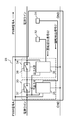
- FIG. 1 is a side sectional view of a heating cooker 1 according to the present embodiment.
- the heating cooker 1 has a heating chamber 2 having a front opening in the main body.
- a door 3 is provided at the front opening of the heating chamber 2.
- the door 3 has a hinge (not shown) at its lower part and a handle 3a at its upper part.
- the door 3 is provided with an operation display unit (not shown) for setting cooking conditions such as cooking temperature, cooking time, and type of an object to be heated, and displaying the set cooking conditions.
- an operation display unit (not shown) for setting cooking conditions such as cooking temperature, cooking time, and type of an object to be heated, and displaying the set cooking conditions.
- the heating cooker 1 has three heating parts, a grill heater unit 10, a high-frequency heating unit 11, and a convection heating unit 12.
- the cooking device 1 cooks an object to be heated using a heating unit selected directly by the user or a heating unit selected according to the cooking conditions set by the user among the three heating units. To do.
- the grill heater unit 10 has a plurality of rod-shaped grill heaters 4 provided on the ceiling of the heating chamber 2.
- the grill heater 4 is constituted by, for example, a sheathed heater.
- the high-frequency heating unit 11 has a magnetron 5, a waveguide 6, and a radiation mechanism 9.
- the high frequency heating unit 11 supplies the microwave generated by the magnetron 5 into the heating chamber 2 via the waveguide 6 by the radiation mechanism 9.
- the radiation mechanism 9 is an antenna that is provided below the bottom surface of the heating chamber 2 and radiates microwaves into the heating chamber 2.
- the radiation mechanism 9 can change the radiation direction of the microwave by the rotating stirrer blade 7.
- the convection heating unit 12 includes a convection heater 13 and a circulation fan 14 provided behind the heating chamber 2.
- the convection heating unit 12 sucks and heats the air in the heating chamber 2 and returns the heated air to the inside of the heating chamber 2, thereby circulating hot air inside the heating chamber 2.
- the heating cooker 1 has a circulation fan motor 15, a cooling fan motor 16, and a stirrer motor 17 as a rotational drive mechanism.
- the circulation fan motor 15 drives the circulation fan 14.
- the cooling fan motor 16 drives a cooling fan 8 for cooling the magnetron 5 and the like.
- the stirrer motor 17 is a drive motor that drives the stirrer blades 7.
- a brushless motor 20 (see FIG. 2) is used as the circulation fan motor 15, the cooling fan motor 16, and the stirrer motor 17.
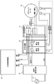
- FIG. 2 is a schematic diagram of a brushless motor 20 that is a drive source of a rotation drive mechanism included in the heating cooker 1 and a circuit that controls the drive of the brushless motor 20.
- FIG. 3 is a block diagram of a circuit that controls the driving of the brushless motor 20 that is the drive source of the rotation drive mechanism included in the cooking device 1.
- the brushless motor 20 has a motor case 26 that houses the stator 18 and the rotor 19 therein.
- the motor case 26 rotatably holds the rotating shaft 19 a of the rotor 19 via a bearing 27.
- the motor control circuit 25 includes a microcomputer and an inverter constituted by an IGBT (Insulated Gate Bipolar Transistor).
- IGBT Insulated Gate Bipolar Transistor
- the DC power supply circuit 22 converts the AC power of the commercial power supply 21 into DC power.
- the motor control circuit 25 receives the converted DC power via a power line provided with the safety device 23.
- the safety device 23 is provided on the outside of the motor case 26 and is configured by a wired logic circuit that does not use program control by a microcomputer.
- a position detection element 24 is provided in the vicinity of the rotor 19.
- the position detection element 24 is composed of a Hall element and detects the position of the rotor 19.
- the motor control circuit 25 receives the position detection signal P output from the position detection element 24 and transmits a feedback signal F based on the position detection signal P to the main body control circuit 30 of the heating cooker 1.
- the main body control circuit 30 generates a PWM signal A and a rotation direction signal R based on the feedback signal F, and transmits these signals to the motor control circuit 25.
- the PWM signal A is a signal for controlling the driving of the brushless motor 20.
- the rotation direction signal R is a signal for designating the rotation direction of the brushless motor 20.
- the motor control circuit 25 drives the brushless motor 20 according to the PWM signal A and the rotation direction signal R from the main body control circuit 30.
- the safety device 23 is provided to forcibly shut off the power supply when an abnormality occurs such that the rotor 19 does not rotate although the main body control circuit 30 outputs the PWM signal A.
- the safety device 23 includes safety circuits 33 and 34 connected in series.
- the motor control circuit 25 receives the DC power converted by the DC power supply circuit 22 via the power supply line provided with the safety circuits 33 and 34.
- the safety device 23 forcibly shuts off the power line in the event of an abnormality using safety circuits 33 and 34 that operate independently.
- the safety circuits 33 and 34 correspond to first and second safety circuits, respectively.
- the safety device 23 further includes a rotation detection element 31 and a rotation detection element 32 in order to detect a rotation abnormality of the rotor 19.
- the rotation detection elements 31 and 32 output a rotation detection signal detected by, for example, a magnetic sensor, an optical sensor, a vibration sensor, or the like in order to detect the rotation of the rotor 19.
- the rotation detection elements 31 and 32 are Hall elements provided close to the rotor 19.
- the rotation detection elements 31 and 32 correspond to first and second rotation detection elements, respectively.
- the safety circuit 33 receives the rotation detection signal B1 output from the rotation detection element 31.
- the safety circuit 34 receives the rotation detection signal B2 output by the rotation detection element 32.
- FIG. 4 is a block diagram of the safety device 23 included in the heating cooker 1.
- the safety circuit 33 includes a switch 37 and an abnormality detection circuit 35.
- the abnormality detection circuit 35 receives the rotation detection signal B1 and the PWM signal A, and controls the switch 37 based on these signals.
- the safety circuit 34 includes a switch 38 and an abnormality detection circuit 36.
- the abnormality detection circuit 36 receives the rotation detection signal B2 and the PWM signal A, and controls the switch 38 based on these signals.
- the switches 37 and 38 are composed of switching elements such as IGBTs (Insulated gate bipolor transistors).
- the switches 37 and 38 are connected in series to the power supply line so that the power supply line is cut off when at least one of them is cut off.
- the switches 37 and 38 correspond to first and second switches, respectively.
- the abnormality detection circuits 35 and 36 correspond to first and second abnormality detection circuits, respectively.
- FIG. 5A shows a logic circuit (XNOR gate) that realizes the functions of the abnormality detection circuits 35 and 36.
- FIG. 5B shows a truth table of the logic circuit shown in FIG. 5A.
- “Hi” in the rotation detection signals B 1 and B 2 represents detection of the rotation state of the rotor 19.
- “Lo” in the rotation detection signals B1 and B2 represents the non-detection of the rotation state of the rotor 19, that is, the detection of the stop state of the rotor 19.
- Hi at the output X of the logic circuit shown in FIG. 5A represents an on signal for the switches 37 and 38
- “Lo” represents an off signal for the switches 37 and 38.
- This embodiment has safety circuits 33 and 34 provided on the power supply line and having switches 37 and 38, respectively.
- the safety device may have at least one safety circuit having at least one switch that operates based on a signal from at least one rotation detecting element.
- the safety device reliably shuts off the power line connected to the brushless motor even if the rotor of the brushless motor is forcibly stopped. To do.
- this aspect can provide a safe and highly reliable cooking device that can maintain the temperature of the brushless motor at a safe temperature.
- the present disclosure is applicable to a heating cooker.
Abstract
Disclosed is a heating cooker that is provided with a heating chamber, a heating unit, a brushless motor, a main body control circuit, a direct current power supply circuit, a motor control circuit, and a safety device. The brushless motor is a drive source for a rotation drive mechanism included in the heating unit. The main body control circuit outputs a drive signal for the brushless motor. The direct current power supply circuit supplies the brushless motor with direct current power. The motor control circuit controls drive of the brushless motor corresponding to the drive signal. The safety device comprises a wired logic circuit. The safety device has: a rotation detection element that is configured to detect the rotation state of a rotor of the brushless motor, and output a rotation detection signal; and a switch that cuts off a power supply line connected to the direct current power supply circuit. The safety device controls the switch corresponding to the rotation detection signal and the drive signal. According to this embodiment of the present invention, the highly safe and highly reliable heating cooker using the brushless motor as the drive source for the rotation drive mechanism can be provided.
Description
本開示は、加熱調理器に関し、特に加熱調理器に含まれる回転駆動機構のための安全装置に関する。
The present disclosure relates to a cooking device, and more particularly to a safety device for a rotational drive mechanism included in the cooking device.
従来、高周波加熱、輻射加熱、対流加熱の三つの機能を備えた加熱調理器が知られている。この種の加熱調理器は、回転駆動機構の駆動源として、発熱部品を冷却するための冷却ファン用のモータと、対流加熱のための循環ファン用のモータと、高周波加熱のための放射機構を駆動するモータとを有する。
Conventionally, a cooking device having three functions of high-frequency heating, radiation heating, and convection heating is known. This type of heating cooker has a motor for a cooling fan for cooling a heat-generating component, a motor for a circulation fan for convection heating, and a radiation mechanism for high-frequency heating as a driving source of a rotation driving mechanism. And a motor to be driven.
これらのモータとして、構造が簡単で安価であるため、一般的に隈取磁極型モータが用いられる。しかし、隈取磁極型モータは、出力があまり大きくないにも関わらず、大きくて重い構造を有する。隈取磁極型モータは、効率が悪く回転数が低い。隈取磁極型モータは、構造上、逆回転できない。
As these motors, a simple magnetic pole type motor is generally used because of its simple structure and low cost. However, the trapped magnetic pole type motor has a large and heavy structure although the output is not so large. The tapped magnetic pole type motor is inefficient and has a low rotational speed. The reverse pole type motor cannot be rotated in reverse due to its structure.
隈取磁極型モータの代わりに、ブラシレスDCモータ(以下、ブラシレスモータという)を使用することが可能である。ブラシレスモータは小型軽量である。ブラシレスモータを使用すると、モータの回転数を高く設定することが可能で、かつ、モータの回転制御を容易に行うことができる。さらに最近、価格も低下しつつある。
A brushless DC motor (hereinafter referred to as a brushless motor) can be used in place of the magnetic pole type motor. The brushless motor is small and light. When a brushless motor is used, the number of rotations of the motor can be set high, and the rotation control of the motor can be easily performed. More recently, prices have been declining.
このように、ブラシレスモータを、加熱調理器における回転駆動機構の駆動源として用いた場合、多くの利点がある。特許文献1は、回転駆動機構の駆動源としてブラシレスモータを用いた加熱調理器を開示している。
Thus, when the brushless motor is used as the drive source of the rotation drive mechanism in the cooking device, there are many advantages. Patent Document 1 discloses a cooking device that uses a brushless motor as a drive source of a rotation drive mechanism.
電気機器に関しては、安全性の観点から厳しい規格が設定されている。例えば、電気機器に含まれるモータのロータを強制的に止めた場合でも、モータ本体の温度を安全な温度に維持することを求める安全基準を規定する国もある。
Strict standards are set for electrical equipment from the viewpoint of safety. For example, some countries stipulate safety standards that require the temperature of the motor body to be maintained at a safe temperature even when the rotor of the motor included in the electrical device is forcibly stopped.
ブラシレスモータにおける駆動制御は、コンピュータ制御により行われる。加熱調理器に含まれる回転駆動機構の駆動源としてブラシレスモータを用いた場合、コンピュータ制御にいかなる問題が生じても、システムの暴走などの重大な事態を招かないようにするシステム設計が重要である。
The drive control in the brushless motor is performed by computer control. When a brushless motor is used as the drive source of the rotary drive mechanism included in the cooking device, it is important to design a system that will not cause a serious situation such as system runaway regardless of any computer control problems. .
本開示は、回転駆動機構の駆動源としてブラシレスモータを用いた加熱調理器において、ブラシレスモータのロータを強制的に止めても、ブラシレスモータの温度を安全な温度に維持できる、安全性および信頼性の高い加熱調理器を提供することを目的とする。
The present disclosure relates to a safety and reliability in which the temperature of a brushless motor can be maintained at a safe temperature even when the rotor of the brushless motor is forcibly stopped in a cooking device using a brushless motor as a drive source of a rotation drive mechanism. An object of the present invention is to provide a cooking device with a high temperature.
本開示の一態様の加熱調理器は、加熱室と加熱部とブラシレスモータと本体制御回路と直流電源回路とモータ制御回路と安全装置とを備える。
The cooking device according to one aspect of the present disclosure includes a heating chamber, a heating unit, a brushless motor, a main body control circuit, a DC power supply circuit, a motor control circuit, and a safety device.
加熱室は被加熱物を収容する。加熱部は、加熱室内の被加熱物を加熱する。ブラシレスモータは、加熱部に含まれる回転駆動機構の駆動源である。本体制御回路は、ブラシレスモータのための駆動信号を出力する。直流電源回路は、ブラシレスモータに直流電力を供給する。モータ制御回路は、駆動信号に応じてブラシレスモータの駆動を制御する。
The heating chamber accommodates the object to be heated. The heating unit heats an object to be heated in the heating chamber. The brushless motor is a drive source of a rotation drive mechanism included in the heating unit. The main body control circuit outputs a drive signal for the brushless motor. The DC power supply circuit supplies DC power to the brushless motor. The motor control circuit controls the drive of the brushless motor according to the drive signal.
安全装置は、ワイヤードロジック(結線論理)回路によって構成される。安全装置は、ブラシレスモータのロータの回転状態を検出して回転検出信号を出力するように構成された回転検出素子と、直流電源回路に接続された電源ラインを遮断するスイッチとを有する。安全装置は、回転検出信号と駆動信号とに応じてスイッチを制御する。
The safety device is composed of a wired logic circuit. The safety device includes a rotation detection element configured to detect a rotation state of the rotor of the brushless motor and output a rotation detection signal, and a switch that cuts off a power supply line connected to the DC power supply circuit. The safety device controls the switch according to the rotation detection signal and the drive signal.
本態様によれば、回転駆動機構の駆動源としてブラシレスモータを用いた加熱調理器において、ブラシレスモータのロータが強制的に止められても、安全装置がブラシレスモータに接続された電源ラインを確実に遮断する。その結果、本態様は、ブラシレスモータの温度を安全な温度に維持できる、安全性および信頼性の高い加熱調理器を提供することができる。
According to this aspect, in a heating cooker using a brushless motor as a drive source of the rotation drive mechanism, even if the rotor of the brushless motor is forcibly stopped, the safety device reliably connects the power line connected to the brushless motor. Cut off. As a result, this aspect can provide a safe and highly reliable cooking device that can maintain the temperature of the brushless motor at a safe temperature.
本態様の安全装置は、ワイヤードロジック回路を用いて構成される。このため、本態様の安全装置は、マイクロコンピュータが暴走したり、プログラムに不具合があったりしても、ブラシレスモータを安全に停止させることができる。
The safety device of this aspect is configured using a wired logic circuit. For this reason, the safety device of this aspect can safely stop the brushless motor even if the microcomputer runs away or there is a problem with the program.
本開示の第1の態様の加熱調理器は、加熱室と加熱部とブラシレスモータと本体制御回路と直流電源回路とモータ制御回路と安全装置とを備える。
The heating cooker according to the first aspect of the present disclosure includes a heating chamber, a heating unit, a brushless motor, a main body control circuit, a DC power supply circuit, a motor control circuit, and a safety device.
加熱室は被加熱物を収容する。加熱部は、加熱室内の被加熱物を加熱する。ブラシレスモータは、加熱部に含まれる回転駆動機構の駆動源である。本体制御回路は、ブラシレスモータのための駆動信号を出力する。直流電源回路は、ブラシレスモータに直流電力を供給する。モータ制御回路は、駆動信号に応じてブラシレスモータの駆動を制御する。
The heating chamber accommodates the object to be heated. The heating unit heats an object to be heated in the heating chamber. The brushless motor is a drive source of a rotation drive mechanism included in the heating unit. The main body control circuit outputs a drive signal for the brushless motor. The DC power supply circuit supplies DC power to the brushless motor. The motor control circuit controls the drive of the brushless motor according to the drive signal.
安全装置は、ワイヤードロジック回路によって構成される。安全装置は、ブラシレスモータのロータの回転状態を検出して回転検出信号を出力するように構成された回転検出素子と、直流電源回路に接続された電源ラインを遮断するスイッチとを有する。安全装置は、回転検出信号と駆動信号とに応じてスイッチを制御する。
The safety device consists of a wired logic circuit. The safety device includes a rotation detection element configured to detect a rotation state of the rotor of the brushless motor and output a rotation detection signal, and a switch that cuts off a power supply line connected to the DC power supply circuit. The safety device controls the switch according to the rotation detection signal and the drive signal.
本開示の第2の態様の加熱調理器によれば、第1の態様において、安全装置が、第1異常検出回路および第2異常検出回路を含む。回転検出素子が、第1回転検出素子および第2回転検出素子を含む。スイッチが、電源ラインに直列に接続された第1スイッチおよび第2スイッチを含む。
According to the cooking device of the second aspect of the present disclosure, in the first aspect, the safety device includes a first abnormality detection circuit and a second abnormality detection circuit. The rotation detection element includes a first rotation detection element and a second rotation detection element. The switch includes a first switch and a second switch connected in series to the power line.
第1異常検出回路が、駆動信号と第1回転検出素子により出力された回転検出信号とに応じて第1スイッチを制御する。第2異常検出回路が、駆動信号と第2回転検出素子により出力された回転検出信号とに応じて第2スイッチを制御する。
The first abnormality detection circuit controls the first switch according to the drive signal and the rotation detection signal output by the first rotation detection element. The second abnormality detection circuit controls the second switch according to the drive signal and the rotation detection signal output by the second rotation detection element.
本開示の第3の態様の加熱調理器によれば、第2の態様において、駆動信号が運転指令を表し、かつ、第1回転検出素子により出力された回転検出信号がロータの停止状態を表す場合、第1異常検出回路が、電源ラインを遮断するように第1スイッチを制御する。
According to the heating cooker of the third aspect of the present disclosure, in the second aspect, the drive signal represents an operation command, and the rotation detection signal output by the first rotation detection element represents a stopped state of the rotor. In this case, the first abnormality detection circuit controls the first switch so as to cut off the power supply line.
駆動信号が運転指令を表し、かつ、第2回転検出素子により出力された回転検出信号がロータの停止状態を表す場合、第2異常検出回路が、電源ラインを遮断するように第2スイッチを制御する。
When the drive signal indicates an operation command and the rotation detection signal output by the second rotation detection element indicates a stopped state of the rotor, the second abnormality detection circuit controls the second switch so as to cut off the power line. To do.
本開示の第4の態様の加熱調理器によれば、第1の態様において、加熱部が対流加熱ユニットを備え、ブラシレスモータが、対流加熱ユニットに含まれた循環ファンを駆動する循環ファンモータとして用いられる。
According to the cooking device of the fourth aspect of the present disclosure, in the first aspect, the heating unit includes a convection heating unit, and the brushless motor is a circulation fan motor that drives a circulation fan included in the convection heating unit. Used.
本開示の第5の態様の加熱調理器によれば、第1の態様において、加熱部が高周波加熱ユニットを備え、ブラシレスモータが、高周波加熱ユニットに含まれた冷却ファンを駆動する冷却ファンモータとして用いられる。
According to the cooking device of the fifth aspect of the present disclosure, in the first aspect, the heating unit includes a high-frequency heating unit, and the brushless motor is a cooling fan motor that drives a cooling fan included in the high-frequency heating unit. Used.
本開示の第6の態様の加熱調理器によれば、第1の態様において、加熱部が高周波加熱ユニットを備え、ブラシレスモータが、高周波加熱ユニットに含まれた放射機構を駆動する駆動モータとして用いられる。
According to the cooking device of the sixth aspect of the present disclosure, in the first aspect, the heating unit includes a high-frequency heating unit, and the brushless motor is used as a drive motor that drives a radiation mechanism included in the high-frequency heating unit. It is done.
以下、本開示の実施の形態について、図面を参照しながら説明する。
Hereinafter, embodiments of the present disclosure will be described with reference to the drawings.
実施の形態はいずれも本開示の一具体例である。実施の形態において示される数値、形状、構成などは一例であり、本開示を限定するものではない。
Each embodiment is a specific example of the present disclosure. Numerical values, shapes, configurations, and the like shown in the embodiments are merely examples, and do not limit the present disclosure.
以下の実施の形態は、本開示の安全装置を、高周波加熱機能、輻射加熱機能、および、対流加熱機能を備えた加熱調理器に適用した例である。しかし、本開示はこのような加熱調理器に限定されるものではない。
The following embodiment is an example in which the safety device of the present disclosure is applied to a cooking device having a high-frequency heating function, a radiation heating function, and a convection heating function. However, the present disclosure is not limited to such a cooking device.
図1は、本実施の形態の加熱調理器1の側面断面図である。図1に示すように、加熱調理器1は、その本体内に、前面開口を有する加熱室2を有する。加熱室2の前面開口に、扉3が設けられる。扉3は、その下部にヒンジ(図示せず)を有し、その上部に把手3aを有する。
FIG. 1 is a side sectional view of a heating cooker 1 according to the present embodiment. As shown in FIG. 1, the heating cooker 1 has a heating chamber 2 having a front opening in the main body. A door 3 is provided at the front opening of the heating chamber 2. The door 3 has a hinge (not shown) at its lower part and a handle 3a at its upper part.
扉3には、調理温度、調理時間、および、被加熱物の種類などの調理条件を設定し、設定された調理条件を表示するための操作表示部(図示せず)が設けられる。
The door 3 is provided with an operation display unit (not shown) for setting cooking conditions such as cooking temperature, cooking time, and type of an object to be heated, and displaying the set cooking conditions.
加熱調理器1は、グリルヒータユニット10、高周波加熱ユニット11、対流加熱ユニット12の三つの加熱部を有する。
The heating cooker 1 has three heating parts, a grill heater unit 10, a high-frequency heating unit 11, and a convection heating unit 12.
加熱調理器1は、三つの加熱部のうちの、使用者により直接選択された加熱部、または、使用者により設定された調理条件に応じて選択された加熱部を用いて被加熱物を調理する。
The cooking device 1 cooks an object to be heated using a heating unit selected directly by the user or a heating unit selected according to the cooking conditions set by the user among the three heating units. To do.
グリルヒータユニット10は、加熱室2の天井に設けられた複数の棒状のグリルヒータ4を有する。グリルヒータ4は、例えば、シーズヒータによって構成される。
The grill heater unit 10 has a plurality of rod-shaped grill heaters 4 provided on the ceiling of the heating chamber 2. The grill heater 4 is constituted by, for example, a sheathed heater.
高周波加熱ユニット11は、マグネトロン5と導波管6と放射機構9とを有する。高周波加熱ユニット11は、マグネトロン5によって生成されたマイクロ波を、導波管6を経由して放射機構9により加熱室2内に供給する。
The high-frequency heating unit 11 has a magnetron 5, a waveguide 6, and a radiation mechanism 9. The high frequency heating unit 11 supplies the microwave generated by the magnetron 5 into the heating chamber 2 via the waveguide 6 by the radiation mechanism 9.
放射機構9は、加熱室2の底面の下方に設けられ、マイクロ波を加熱室2内に放射するためのアンテナである。放射機構9は、回転するスタラ羽根7により、マイクロ波の放射方向を変更することができる。
The radiation mechanism 9 is an antenna that is provided below the bottom surface of the heating chamber 2 and radiates microwaves into the heating chamber 2. The radiation mechanism 9 can change the radiation direction of the microwave by the rotating stirrer blade 7.
対流加熱ユニット12は、加熱室2の後方に設けられたコンベクションヒータ13および循環ファン14を備える。対流加熱ユニット12は、加熱室2内の空気を吸引して加熱し、加熱した空気を加熱室2の内部に戻すことで、加熱室2の内部で熱風を循環させる。
The convection heating unit 12 includes a convection heater 13 and a circulation fan 14 provided behind the heating chamber 2. The convection heating unit 12 sucks and heats the air in the heating chamber 2 and returns the heated air to the inside of the heating chamber 2, thereby circulating hot air inside the heating chamber 2.
加熱調理器1は、回転駆動機構として循環ファンモータ15と冷却ファンモータ16とスタラモータ17とを有する。循環ファンモータ15は循環ファン14を駆動する。冷却ファンモータ16は、マグネトロン5などを冷却するための冷却ファン8を駆動する。スタラモータ17はスタラ羽根7を駆動する駆動モータである。
The heating cooker 1 has a circulation fan motor 15, a cooling fan motor 16, and a stirrer motor 17 as a rotational drive mechanism. The circulation fan motor 15 drives the circulation fan 14. The cooling fan motor 16 drives a cooling fan 8 for cooling the magnetron 5 and the like. The stirrer motor 17 is a drive motor that drives the stirrer blades 7.
本実施の形態では、循環ファンモータ15、冷却ファンモータ16、スタラモータ17として、ブラシレスモータ20(図2参照)が用いられる。
In this embodiment, a brushless motor 20 (see FIG. 2) is used as the circulation fan motor 15, the cooling fan motor 16, and the stirrer motor 17.
以下、加熱調理器1で用いられた回転駆動機構の安全装置について説明する。
Hereinafter, the safety device of the rotation drive mechanism used in the heating cooker 1 will be described.
図2は、加熱調理器1に含まれる回転駆動機構の駆動源であるブラシレスモータ20と、ブラシレスモータ20の駆動を制御する回路との模式図である。図3は、加熱調理器1に含まれる回転駆動機構の駆動源であるブラシレスモータ20の駆動を制御する回路のブロック図である。
FIG. 2 is a schematic diagram of a brushless motor 20 that is a drive source of a rotation drive mechanism included in the heating cooker 1 and a circuit that controls the drive of the brushless motor 20. FIG. 3 is a block diagram of a circuit that controls the driving of the brushless motor 20 that is the drive source of the rotation drive mechanism included in the cooking device 1.
図2に示すように、ブラシレスモータ20は、ステータ18とロータ19とを内部に収容するモータケース26を有する。モータケース26は、軸受け27を介してロータ19の回転軸19aを回転自在に保持する。
As shown in FIG. 2, the brushless motor 20 has a motor case 26 that houses the stator 18 and the rotor 19 therein. The motor case 26 rotatably holds the rotating shaft 19 a of the rotor 19 via a bearing 27.
モータケース26の内部には、モータ制御回路25が、ロータ19に近接して設けられる。モータ制御回路25は、マイクロコンピュータと、IGBT(Insulated Gate Bipolar Transistor)で構成されたインバータとを含む。
In the motor case 26, a motor control circuit 25 is provided close to the rotor 19. The motor control circuit 25 includes a microcomputer and an inverter constituted by an IGBT (Insulated Gate Bipolar Transistor).
図2、図3に示すように、直流電源回路22は、商用電源21の交流電力を直流電力に変換する。モータ制御回路25は、変換された直流電力を、安全装置23が設けられた電源ラインを経由して受信する。安全装置23は、モータケース26の外側に設けられ、マイクロコンピュータによるプログラム制御を用いないワイヤードロジック回路によって構成される。
2 and 3, the DC power supply circuit 22 converts the AC power of the commercial power supply 21 into DC power. The motor control circuit 25 receives the converted DC power via a power line provided with the safety device 23. The safety device 23 is provided on the outside of the motor case 26 and is configured by a wired logic circuit that does not use program control by a microcomputer.
ロータ19に近接して、位置検出素子24が設けられる。位置検出素子24は、ホール素子で構成され、ロータ19の位置を検出する。
A position detection element 24 is provided in the vicinity of the rotor 19. The position detection element 24 is composed of a Hall element and detects the position of the rotor 19.
モータ制御回路25は、位置検出素子24により出力された位置検出信号Pを受信し、位置検出信号Pに基づいたフィードバック信号Fを、加熱調理器1の本体制御回路30に送信する。
The motor control circuit 25 receives the position detection signal P output from the position detection element 24 and transmits a feedback signal F based on the position detection signal P to the main body control circuit 30 of the heating cooker 1.
本体制御回路30は、フィードバック信号Fに基づいてPWM信号Aと回転方向信号Rとを生成し、これらの信号をモータ制御回路25に送信する。PWM信号Aは、ブラシレスモータ20の駆動を制御するための信号である。回転方向信号Rは、ブラシレスモータ20の回転方向を指定するための信号である。
The main body control circuit 30 generates a PWM signal A and a rotation direction signal R based on the feedback signal F, and transmits these signals to the motor control circuit 25. The PWM signal A is a signal for controlling the driving of the brushless motor 20. The rotation direction signal R is a signal for designating the rotation direction of the brushless motor 20.
モータ制御回路25は、本体制御回路30からのPWM信号Aと回転方向信号Rとに応じて、ブラシレスモータ20を駆動する。
The motor control circuit 25 drives the brushless motor 20 according to the PWM signal A and the rotation direction signal R from the main body control circuit 30.
安全装置23は、本体制御回路30がPWM信号Aを出力しているにも関わらず、ロータ19が回転しないなどの異常時に、強制的に電源を遮断するために設けられる。
The safety device 23 is provided to forcibly shut off the power supply when an abnormality occurs such that the rotor 19 does not rotate although the main body control circuit 30 outputs the PWM signal A.
具体的には、安全装置23は、直列接続された安全回路33、34を有する。モータ制御回路25は、直流電源回路22により変換された直流電力を、安全回路33、34が設けられた電源ラインを経由して受信する。
Specifically, the safety device 23 includes safety circuits 33 and 34 connected in series. The motor control circuit 25 receives the DC power converted by the DC power supply circuit 22 via the power supply line provided with the safety circuits 33 and 34.
安全装置23は、独立して作動する安全回路33、34を用いて、異常時に電源ラインを強制的に遮断する。安全回路33、34は、第1、第2安全回路にそれぞれ相当する。
The safety device 23 forcibly shuts off the power line in the event of an abnormality using safety circuits 33 and 34 that operate independently. The safety circuits 33 and 34 correspond to first and second safety circuits, respectively.
安全装置23は、ロータ19の回転異常を検出するために、回転検出素子31、回転検出素子32をさらに有する。回転検出素子31、32は、ロータ19の回転を検出するために、例えば磁気センサ、光センサ、振動センサなどにより検出される回転検出信号を出力する。
The safety device 23 further includes a rotation detection element 31 and a rotation detection element 32 in order to detect a rotation abnormality of the rotor 19. The rotation detection elements 31 and 32 output a rotation detection signal detected by, for example, a magnetic sensor, an optical sensor, a vibration sensor, or the like in order to detect the rotation of the rotor 19.
本実施の形態では、回転検出素子31、32は、ロータ19に近接して設けられたホール素子である。回転検出素子31、32は、第1、第2回転検出素子にそれぞれ相当する。
In the present embodiment, the rotation detection elements 31 and 32 are Hall elements provided close to the rotor 19. The rotation detection elements 31 and 32 correspond to first and second rotation detection elements, respectively.
安全回路33は、回転検出素子31により出力される回転検出信号B1を受信する。安全回路34は、回転検出素子32により出力される回転検出信号B2を受信する。
The safety circuit 33 receives the rotation detection signal B1 output from the rotation detection element 31. The safety circuit 34 receives the rotation detection signal B2 output by the rotation detection element 32.
図4は、加熱調理器1に含まれる安全装置23のブロック図である。図4に示すように、安全回路33は、スイッチ37と異常検出回路35とを有する。異常検出回路35は、回転検出信号B1とPWM信号Aとを受信し、これらの信号に基づいてスイッチ37を制御する。
FIG. 4 is a block diagram of the safety device 23 included in the heating cooker 1. As shown in FIG. 4, the safety circuit 33 includes a switch 37 and an abnormality detection circuit 35. The abnormality detection circuit 35 receives the rotation detection signal B1 and the PWM signal A, and controls the switch 37 based on these signals.
安全回路34は、スイッチ38と異常検出回路36とを有する。異常検出回路36は、回転検出信号B2とPWM信号Aとを受信し、これらの信号に基づいてスイッチ38を制御する。
The safety circuit 34 includes a switch 38 and an abnormality detection circuit 36. The abnormality detection circuit 36 receives the rotation detection signal B2 and the PWM signal A, and controls the switch 38 based on these signals.
スイッチ37、38は、IGBT(Insulated gate bipolor transistor)などのスイッチング素子で構成される。スイッチ37、38は、少なくとも一方が遮断されると電源ラインが遮断されるように、電源ラインに直列に接続される。スイッチ37、38は、第1、第2スイッチにそれぞれ相当する。異常検出回路35、36は、第1、第2異常検出回路にそれぞれ相当する。
The switches 37 and 38 are composed of switching elements such as IGBTs (Insulated gate bipolor transistors). The switches 37 and 38 are connected in series to the power supply line so that the power supply line is cut off when at least one of them is cut off. The switches 37 and 38 correspond to first and second switches, respectively. The abnormality detection circuits 35 and 36 correspond to first and second abnormality detection circuits, respectively.
図5Aは、異常検出回路35、36の機能を実現する論理回路(XNORゲート)を示す。図5Bは、図5Aに示す論理回路の真理値表を示す。
FIG. 5A shows a logic circuit (XNOR gate) that realizes the functions of the abnormality detection circuits 35 and 36. FIG. 5B shows a truth table of the logic circuit shown in FIG. 5A.
図5Bに示す真理値表において、PWM信号Aにおける「Hi」は、ブラシレスモータ20に対する運転指令を表す。PWM信号Aにおける「Lo」は、ブラシレスモータ20に対する停止指令を表す。
In the truth table shown in FIG. 5B, “Hi” in the PWM signal A represents an operation command for the brushless motor 20. “Lo” in the PWM signal A represents a stop command for the brushless motor 20.
回転検出信号B1、B2における「Hi」は、ロータ19の回転状態の検出を表す。回転検出信号B1、B2における「Lo」は、ロータ19の回転状態の不検出、すなわち、ロータ19の停止状態の検出を表す。
“Hi” in the rotation detection signals B 1 and B 2 represents detection of the rotation state of the rotor 19. “Lo” in the rotation detection signals B1 and B2 represents the non-detection of the rotation state of the rotor 19, that is, the detection of the stop state of the rotor 19.
図5Aに示す論理回路の出力Xにおける「Hi」は、スイッチ37、38に対するオン信号を表し、「Lo」は、スイッチ37、38に対するオフ信号を表す。
“Hi” at the output X of the logic circuit shown in FIG. 5A represents an on signal for the switches 37 and 38, and “Lo” represents an off signal for the switches 37 and 38.
図5Bに示すように、PWM信号Aが「Hi」、回転検出信号B1、B2が「Lo」である場合、スイッチ37、38がオフされて電源ラインが遮断される。その結果、ブラシレスモータ20の作動中に、何らかの理由で意図せずロータ19が回転を停止した場合、安全装置23が電源ラインを遮断することで、ブラシレスモータ20を安全に停止させる。
As shown in FIG. 5B, when the PWM signal A is “Hi” and the rotation detection signals B1 and B2 are “Lo”, the switches 37 and 38 are turned off to cut off the power line. As a result, when the rotor 19 stops unintentionally for some reason during the operation of the brushless motor 20, the safety device 23 interrupts the power supply line, so that the brushless motor 20 is safely stopped.
本実施の形態は、電源ライン上に設けられ、スイッチ37、38をそれぞれ有する安全回路33、34を有する。しかし、本開示はこの構成に限定されるものではない。安全装置が、少なくとも一つの回転検出素子からの信号に基づいて作動する、少なくとも一つのスイッチを有する少なくとも一つの安全回路を有すればよい。
This embodiment has safety circuits 33 and 34 provided on the power supply line and having switches 37 and 38, respectively. However, the present disclosure is not limited to this configuration. The safety device may have at least one safety circuit having at least one switch that operates based on a signal from at least one rotation detecting element.
本態様によれば、回転駆動機構の駆動源としてブラシレスモータを用いた加熱調理器において、ブラシレスモータのロータを強制的に止めても、安全装置がブラシレスモータに接続された電源ラインを確実に遮断する。その結果、本態様は、ブラシレスモータの温度を安全な温度に維持できる、安全性および信頼性の高い加熱調理器を提供することができる。
According to this aspect, in a cooking device using a brushless motor as a drive source of the rotation drive mechanism, the safety device reliably shuts off the power line connected to the brushless motor even if the rotor of the brushless motor is forcibly stopped. To do. As a result, this aspect can provide a safe and highly reliable cooking device that can maintain the temperature of the brushless motor at a safe temperature.
上述の通り、本開示は加熱調理器に適用可能である。
As described above, the present disclosure is applicable to a heating cooker.
1 加熱調理器
2 加熱室
3 扉
4 グリルヒータ
5 マグネトロン
6 導波管
7 スタラ羽根
8 冷却ファン
9 放射機構
10 グリルヒータユニット
11 高周波加熱ユニット
12 対流加熱ユニット
13 コンベクションヒータ
14 循環ファン
15 循環ファンモータ
16 冷却ファンモータ
17 スタラモータ
18 ステータ
19 ロータ
20 ブラシレスモータ
21 商用電源
22 直流電源回路
23 安全装置
24 位置検出素子
25 モータ制御回路
30 本体制御回路
31,32 回転検出素子
33,34 安全回路
35,36 異常検出回路
37,38 スイッチ DESCRIPTION OFSYMBOLS 1 Heating cooker 2 Heating chamber 3 Door 4 Grill heater 5 Magnetron 6 Waveguide 7 Starr blade 8 Cooling fan 9 Radiation mechanism 10 Grill heater unit 11 High frequency heating unit 12 Convection heating unit 13 Convection heater 14 Circulation fan 15 Circulation fan motor 16 Cooling fan motor 17 Stirrer motor 18 Stator 19 Rotor 20 Brushless motor 21 Commercial power supply 22 DC power supply circuit 23 Safety device 24 Position detection element 25 Motor control circuit 30 Main body control circuit 31, 32 Rotation detection element 33, 34 Safety circuit 35, 36 Abnormality detection Circuit 37, 38 switch
2 加熱室
3 扉
4 グリルヒータ
5 マグネトロン
6 導波管
7 スタラ羽根
8 冷却ファン
9 放射機構
10 グリルヒータユニット
11 高周波加熱ユニット
12 対流加熱ユニット
13 コンベクションヒータ
14 循環ファン
15 循環ファンモータ
16 冷却ファンモータ
17 スタラモータ
18 ステータ
19 ロータ
20 ブラシレスモータ
21 商用電源
22 直流電源回路
23 安全装置
24 位置検出素子
25 モータ制御回路
30 本体制御回路
31,32 回転検出素子
33,34 安全回路
35,36 異常検出回路
37,38 スイッチ DESCRIPTION OF
Claims (6)
- 被加熱物を収容するように構成された加熱室と、
前記加熱室内の前記被加熱物を加熱するように構成された加熱部と、
前記加熱部に含まれる回転駆動機構の駆動源であるブラシレスモータと、
前記ブラシレスモータのための駆動信号を出力するように構成された本体制御回路と、
前記ブラシレスモータに直流電力を供給するように構成された直流電源回路と、
前記駆動信号に応じて前記ブラシレスモータの駆動を制御するように構成されたモータ制御回路と、
ワイヤードロジック回路によって構成され、前記ブラシレスモータのロータの回転状態を検出して回転検出信号を出力するように構成された回転検出素子、および、前記直流電源回路に接続された電源ラインを遮断するスイッチを有し、前記回転検出信号と前記駆動信号とに応じて前記スイッチを制御するように構成された安全装置と、を備えた加熱調理器。 A heating chamber configured to accommodate an object to be heated;
A heating unit configured to heat the object to be heated in the heating chamber;
A brushless motor which is a drive source of a rotation drive mechanism included in the heating unit;
A main body control circuit configured to output a drive signal for the brushless motor;
A DC power supply circuit configured to supply DC power to the brushless motor;
A motor control circuit configured to control the drive of the brushless motor in response to the drive signal;
A rotation detection element configured by a wired logic circuit, configured to detect a rotation state of the rotor of the brushless motor and output a rotation detection signal, and a switch for cutting off a power supply line connected to the DC power supply circuit And a safety device configured to control the switch according to the rotation detection signal and the drive signal. - 前記安全装置が、第1異常検出回路および第2異常検出回路を含み、前記回転検出素子が、第1回転検出素子および第2回転検出素子を含み、前記スイッチが、前記電源ラインに直列に接続された第1スイッチおよび第2スイッチを含み、
前記第1異常検出回路が、前記駆動信号と前記第1回転検出素子により出力された前記回転検出信号とに応じて前記第1スイッチを制御するように構成され、前記第2異常検出回路が、前記駆動信号と前記第2回転検出素子により出力された前記回転検出信号とに応じて前記第2スイッチを制御するように構成された、請求項1に記載の加熱調理器。 The safety device includes a first abnormality detection circuit and a second abnormality detection circuit, the rotation detection element includes a first rotation detection element and a second rotation detection element, and the switch is connected in series to the power line. A first switch and a second switch,
The first abnormality detection circuit is configured to control the first switch according to the drive signal and the rotation detection signal output by the first rotation detection element, and the second abnormality detection circuit is The cooking device according to claim 1, wherein the cooking device is configured to control the second switch according to the drive signal and the rotation detection signal output by the second rotation detection element. - 前記駆動信号が運転指令を表し、かつ、前記第1回転検出素子により出力された前記回転検出信号が前記ロータの停止状態を表す場合、前記第1異常検出回路が、前記電源ラインを遮断するように前記第1スイッチを制御するように構成され、
前記駆動信号が運転指令を表し、かつ、前記第2回転検出素子により出力された前記回転検出信号が前記ロータの停止状態を表す場合、前記第2異常検出回路が、前記電源ラインを遮断するように前記第2スイッチを制御するように構成された、請求項2に記載の加熱調理器。 When the drive signal represents an operation command and the rotation detection signal output by the first rotation detection element represents a stopped state of the rotor, the first abnormality detection circuit is configured to cut off the power line. Is configured to control the first switch,
When the drive signal represents an operation command and the rotation detection signal output by the second rotation detection element represents a stopped state of the rotor, the second abnormality detection circuit is configured to cut off the power line. The cooking device according to claim 2, wherein the cooking device is configured to control the second switch. - 前記加熱部が対流加熱ユニットを備え、前記ブラシレスモータが、前記対流加熱ユニットに含まれた循環ファンを駆動する循環ファンモータとして用いられた、請求項1に記載の加熱調理器。 The heating cooker according to claim 1, wherein the heating unit includes a convection heating unit, and the brushless motor is used as a circulation fan motor that drives a circulation fan included in the convection heating unit.
- 前記加熱部が高周波加熱ユニットを備え、前記ブラシレスモータが、前記高周波加熱ユニットに含まれた冷却ファンを駆動する冷却ファンモータとして用いられた、請求項1に記載の加熱調理器。 The heating cooker according to claim 1, wherein the heating unit includes a high-frequency heating unit, and the brushless motor is used as a cooling fan motor that drives a cooling fan included in the high-frequency heating unit.
- 前記加熱部が高周波加熱ユニットを備え、前記ブラシレスモータが、前記高周波加熱ユニットに含まれた放射機構を駆動する駆動モータとして用いられた、請求項1に記載の加熱調理器。 The heating cooker according to claim 1, wherein the heating unit includes a high-frequency heating unit, and the brushless motor is used as a drive motor for driving a radiation mechanism included in the high-frequency heating unit.
Priority Applications (4)
| Application Number | Priority Date | Filing Date | Title |
|---|---|---|---|
| US16/465,367 US11903115B2 (en) | 2017-02-24 | 2017-12-04 | Heating cooker |
| CA3047371A CA3047371C (en) | 2017-02-24 | 2017-12-04 | Heating cooker |
| EP17897772.4A EP3587929B1 (en) | 2017-02-24 | 2017-12-04 | Heating cooker |
| CN201780083082.2A CN110168285B (en) | 2017-02-24 | 2017-12-04 | Heating cooker |
Applications Claiming Priority (2)
| Application Number | Priority Date | Filing Date | Title |
|---|---|---|---|
| JP2017033862A JP6788861B2 (en) | 2017-02-24 | 2017-02-24 | Cooker |
| JP2017-033862 | 2017-02-24 |
Publications (1)
| Publication Number | Publication Date |
|---|---|
| WO2018154905A1 true WO2018154905A1 (en) | 2018-08-30 |
Family
ID=63254337
Family Applications (1)
| Application Number | Title | Priority Date | Filing Date |
|---|---|---|---|
| PCT/JP2017/043404 WO2018154905A1 (en) | 2017-02-24 | 2017-12-04 | Heating cooker |
Country Status (7)
| Country | Link |
|---|---|
| US (1) | US11903115B2 (en) |
| EP (1) | EP3587929B1 (en) |
| JP (1) | JP6788861B2 (en) |
| CN (1) | CN110168285B (en) |
| CA (1) | CA3047371C (en) |
| TW (1) | TWI653420B (en) |
| WO (1) | WO2018154905A1 (en) |
Families Citing this family (2)
| Publication number | Priority date | Publication date | Assignee | Title |
|---|---|---|---|---|
| KR102502178B1 (en) * | 2016-01-12 | 2023-02-21 | 삼성전자주식회사 | A cooking apparatus and a method for controlling the same |
| JP7460982B2 (en) | 2019-07-18 | 2024-04-03 | 青島海爾洗衣机有限公司 | washing machine |
Citations (9)
| Publication number | Priority date | Publication date | Assignee | Title |
|---|---|---|---|---|
| JPH0530642A (en) * | 1991-07-23 | 1993-02-05 | Toshiba Corp | Motor drive |
| JPH05144561A (en) * | 1991-11-21 | 1993-06-11 | Matsushita Electric Ind Co Ltd | High frequency heating device |
| JPH11113274A (en) * | 1997-10-03 | 1999-04-23 | Mitsubishi Electric Corp | Emergency stop device of motor |
| JPH11304162A (en) * | 1998-04-22 | 1999-11-05 | Matsushita Electric Ind Co Ltd | Heating cooker |
| JP2001021146A (en) * | 1999-07-09 | 2001-01-26 | Toshiba Corp | Heating and cooking device |
| JP2002014703A (en) * | 2000-06-29 | 2002-01-18 | Toshiba Corp | Plant controller |
| JP2002075622A (en) * | 2000-09-04 | 2002-03-15 | Fuji Electric Co Ltd | Power supply of electromagnetic cooker |
| JP2002089848A (en) * | 2000-09-19 | 2002-03-27 | Toshiba Corp | Electronic oven |
| JP2017015365A (en) | 2015-07-06 | 2017-01-19 | 東芝ホームテクノ株式会社 | Heating cooker |
Family Cites Families (6)
| Publication number | Priority date | Publication date | Assignee | Title |
|---|---|---|---|---|
| JPH02111220A (en) * | 1988-10-19 | 1990-04-24 | Hitachi Ltd | Protecting device for brushless dc motor |
| US6571564B2 (en) * | 2001-10-23 | 2003-06-03 | Shashank Upadhye | Timed container warmer and cooler |
| CN101398681A (en) * | 2007-09-29 | 2009-04-01 | 刘小勇 | Auto cooking device control system based on bus and cooking device |
| DE102012204234A1 (en) * | 2012-03-16 | 2013-09-19 | BSH Bosch und Siemens Hausgeräte GmbH | Microwave combination unit with a fan for cooling |
| DE102012222155A1 (en) * | 2012-12-04 | 2014-06-05 | BSH Bosch und Siemens Hausgeräte GmbH | Microwave apparatus for heating food product i.e pizza, has microwave distribution unit for launching microwaves into cooking space, where position of microwave distribution unit is adjusted at translatory mode by position adjustment device |
| DE102013215846A1 (en) | 2013-08-12 | 2015-02-12 | BSH Bosch und Siemens Hausgeräte GmbH | Household appliance with sound output unit |
-
2017
- 2017-02-24 JP JP2017033862A patent/JP6788861B2/en active Active
- 2017-12-04 EP EP17897772.4A patent/EP3587929B1/en active Active
- 2017-12-04 US US16/465,367 patent/US11903115B2/en active Active
- 2017-12-04 WO PCT/JP2017/043404 patent/WO2018154905A1/en unknown
- 2017-12-04 CA CA3047371A patent/CA3047371C/en active Active
- 2017-12-04 CN CN201780083082.2A patent/CN110168285B/en active Active
- 2017-12-07 TW TW106142936A patent/TWI653420B/en active
Patent Citations (9)
| Publication number | Priority date | Publication date | Assignee | Title |
|---|---|---|---|---|
| JPH0530642A (en) * | 1991-07-23 | 1993-02-05 | Toshiba Corp | Motor drive |
| JPH05144561A (en) * | 1991-11-21 | 1993-06-11 | Matsushita Electric Ind Co Ltd | High frequency heating device |
| JPH11113274A (en) * | 1997-10-03 | 1999-04-23 | Mitsubishi Electric Corp | Emergency stop device of motor |
| JPH11304162A (en) * | 1998-04-22 | 1999-11-05 | Matsushita Electric Ind Co Ltd | Heating cooker |
| JP2001021146A (en) * | 1999-07-09 | 2001-01-26 | Toshiba Corp | Heating and cooking device |
| JP2002014703A (en) * | 2000-06-29 | 2002-01-18 | Toshiba Corp | Plant controller |
| JP2002075622A (en) * | 2000-09-04 | 2002-03-15 | Fuji Electric Co Ltd | Power supply of electromagnetic cooker |
| JP2002089848A (en) * | 2000-09-19 | 2002-03-27 | Toshiba Corp | Electronic oven |
| JP2017015365A (en) | 2015-07-06 | 2017-01-19 | 東芝ホームテクノ株式会社 | Heating cooker |
Non-Patent Citations (1)
| Title |
|---|
| See also references of EP3587929A4 |
Also Published As
| Publication number | Publication date |
|---|---|
| CA3047371A1 (en) | 2018-08-30 |
| CN110168285B (en) | 2021-06-08 |
| CN110168285A (en) | 2019-08-23 |
| CA3047371C (en) | 2021-07-13 |
| EP3587929B1 (en) | 2021-05-19 |
| TWI653420B (en) | 2019-03-11 |
| TW201831833A (en) | 2018-09-01 |
| US11903115B2 (en) | 2024-02-13 |
| EP3587929A4 (en) | 2020-02-19 |
| US20190394839A1 (en) | 2019-12-26 |
| JP2018138858A (en) | 2018-09-06 |
| EP3587929A1 (en) | 2020-01-01 |
| JP6788861B2 (en) | 2020-11-25 |
Similar Documents
| Publication | Publication Date | Title |
|---|---|---|
| US20100039055A1 (en) | Temperature control of motor | |
| US8836257B2 (en) | Household appliance including a fan speed controller | |
| WO2018154905A1 (en) | Heating cooker | |
| JP5981321B2 (en) | Electric tool | |
| JP6065741B2 (en) | Cooker | |
| CN108566697B (en) | Control method and microwave cooking appliance | |
| US10619861B2 (en) | Cooking device and method for preventing cooking device from overheating | |
| KR101052168B1 (en) | Fan drive circuit of electric cooker and electric cooker | |
| KR101233244B1 (en) | Circuit for operating of microwave oven | |
| JP2018179457A (en) | Heating cooker | |
| US20240044513A1 (en) | Cooking appliance | |
| KR20170143359A (en) | Steam Convection Oven | |
| JP5960742B2 (en) | Cooker | |
| JP2016046967A (en) | Power conditioner | |
| JP2015135193A (en) | heating cooker | |
| KR200349499Y1 (en) | Synchronous motor radiant heat structure a microwave | |
| KR100565660B1 (en) | Apparatus and Method for Controlling Combination Mode of The Microwave Oven | |
| JPH03114188A (en) | Induction heating cooking apparatus | |
| JP2008071519A (en) | Heating cooker | |
| KR20090071256A (en) | Apparatus for checking cooling fan ratation for microwave oven | |
| KR20010055389A (en) | A controlling method of cavity temperature in microwave oven | |
| KR20060062220A (en) | Structure of cooling fan motor having a detecting function of fan locking in microwave oven | |
| KR19990010273U (en) | Microwave using synchronous motor with heat dissipation | |
| KR20070114986A (en) | Noise reducing microwave oven | |
| JPH08308719A (en) | Ih rice cooker |
Legal Events
| Date | Code | Title | Description |
|---|---|---|---|
| 121 | Ep: the epo has been informed by wipo that ep was designated in this application |
Ref document number: 17897772 Country of ref document: EP Kind code of ref document: A1 |
|
| ENP | Entry into the national phase |
Ref document number: 3047371 Country of ref document: CA |
|
| NENP | Non-entry into the national phase |
Ref country code: DE |
|
| ENP | Entry into the national phase |
Ref document number: 2017897772 Country of ref document: EP Effective date: 20190924 |