以下、この発明の実施形態について図面に基づいて説明する。この実施形態の表皮材止着具10の説明において、図面に示す互いに直交するXYZ軸方向を基準として、方向を示す。ここでは、X軸方向を前後方向とし、例えば図7に示すように後述する表皮材46の端縁46aが延在する方向にほぼ一致する。表皮材46の端縁46aを、後述する座席のプレート40の孔部49に挿入して取り付ける方向を上下方向とし、上下方向は、X軸方向と直交するZ軸方向であり、後述するクッション材44の厚み方向と一致する。また、前後方向であるX軸方向、及び上下方向であるZ軸方向と交差する方向をY軸方向とし、左右方向と称する。この左右方向に平行な方向を側方ともいう。
Hereinafter, embodiments of the present invention will be described with reference to the drawings. In the description of the skin material fastener 10 of this embodiment, directions are shown with reference to XYZ axial directions orthogonal to each other shown in the drawings. Here, the X-axis direction is the front-rear direction, and substantially coincides with the direction in which an edge 46a of a skin material 46 described later extends, for example, as shown in FIG. The direction in which the end edge 46a of the skin material 46 is inserted into and attached to a hole 49 of the seat plate 40 described later is the vertical direction, and the vertical direction is the Z-axis direction orthogonal to the X-axis direction. It corresponds to the thickness direction of 44. A direction intersecting the X-axis direction that is the front-rear direction and the Z-axis direction that is the up-down direction is referred to as the Y-axis direction, and is referred to as the left-right direction. A direction parallel to the left-right direction is also referred to as a side.
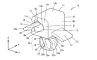
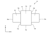
図1~図6はこの発明の第一実施形態を示すもので、この実施形態の表皮材止着具10は、合成樹脂で一体に成形されたものであり、Z軸方向の一方の端部にチャック部14が設けられている。チャック部14は、XZ面に対して平行な一対の側面14a,14bと、XY面に対して平行な側面14c,14dと、YZ面に対して平行な一対の側面14e,14fで形成された立方体である。X軸方向に平行な側面14a,14c,14b,14dが、順に直交し連接して四角柱状となり、側面14a,14c,14b,14dで形成された四角柱状の端部に、側面14eと側面14fが位置している。側面14a,14c,14b,14dの間の4方の角部は、丸く面取りされている。
1 to 6 show a first embodiment of the present invention, and a skin material fastener 10 of this embodiment is integrally formed of synthetic resin and has one end in the Z-axis direction. Is provided with a chuck portion 14. The chuck portion 14 is formed of a pair of side surfaces 14a and 14b parallel to the XZ plane, side surfaces 14c and 14d parallel to the XY plane, and a pair of side surfaces 14e and 14f parallel to the YZ plane. It is a cube. The side surfaces 14a, 14c, 14b, 14d parallel to the X-axis direction are orthogonally connected in order to form a quadrangular prism shape, and the side surface 14e and the side surface 14f are formed at the end portions of the quadrangular column shape formed by the side surfaces 14a, 14c, 14b, 14d. Is located. Four corners between the side surfaces 14a, 14c, 14b, and 14d are rounded and chamfered.
チャック部14の中心部には、X軸方向に平行な溝状の収容部16が、側面14e,14fをX軸方向に貫通して形成されている。収容部16の、YZ面の断面形状は略矢印形状であり、側面14aの少し内側で側面14aに対して平行な平面の内側面16aと、側面14bの内側で内側面16aに対して平行で内側面16aよりZ軸方向の幅が狭い平面の内側面16bと、側面14cの内側で内側面16aの端部と内側面16bの端部に連結する傾斜した平面の内側面16cと、側面14dの内側で内側面16aの端部と内側面16bの端部に連結する傾斜した平面の内側面16dで囲まれて形成されている。内側面16aの中心には、X軸方向に沿う溝状の開口部17が設けられ、開口部17は、側面14aに開口し、収容部16を側面14a側に連通している。開口部17のZ方向の幅は内側面16aよりも小さく、開口部17の両側に内側面16aが同じ幅で位置し、また開口部17の両側に側面14aが同じ幅で位置し、開口部17の両側で、開口部17に向かって突出する形状となっている。
A groove-like accommodation portion 16 parallel to the X-axis direction is formed in the center portion of the chuck portion 14 so as to penetrate the side surfaces 14e and 14f in the X-axis direction. The cross-sectional shape of the YZ surface of the accommodating portion 16 is substantially an arrow shape, and is a flat inner surface 16a parallel to the side surface 14a slightly inside the side surface 14a, and parallel to the inner surface 16a inside the side surface 14b. A flat inner surface 16b having a width narrower in the Z-axis direction than the inner surface 16a, an inclined inner surface 16c connected to an end of the inner surface 16a and an end of the inner surface 16b inside the side surface 14c, and a side surface 14d The inner surface 16a is surrounded by an inclined inner surface 16d connected to the end of the inner surface 16a and the end of the inner surface 16b. A groove-shaped opening 17 along the X-axis direction is provided at the center of the inner side surface 16a. The opening 17 opens to the side surface 14a, and the accommodating portion 16 communicates with the side surface 14a. The width of the opening 17 in the Z direction is smaller than that of the inner side surface 16a, the inner side surface 16a is located on both sides of the opening 17 with the same width, and the side surface 14a is located on both sides of the opening 17 with the same width. On both sides of 17, the shape projects toward opening 17.
これによりチャック部14は、側面14c,14dが、収容部16と開口部17を両側から囲む一対の係止爪19となり、側面14bは、一対の係止爪19基端部を連結する係止爪基端部21となる。なお、開口部17は、内側面16aと側面14aに対して略直角な内周面で連続し、側面14aと開口部17の内周面との角部は丸く面取りされている。内側面16c,16dの途中には、後述する係止用端部材50に係止する突起18が設けられている。突起18は、内側面16c,16dのX軸方向の中心に各々設けられている。
Thus, the side surface 14c, 14d of the chuck portion 14 becomes a pair of locking claws 19 that surround the accommodating portion 16 and the opening portion 17 from both sides, and the side surface 14b is a locking portion that connects the base end portions of the pair of locking claws 19 It becomes the nail base end portion 21. The opening 17 is continuous on the inner peripheral surface 16a and the inner peripheral surface substantially perpendicular to the side surface 14a, and the corners of the side surface 14a and the inner peripheral surface of the opening 17 are rounded and chamfered. In the middle of the inner side surfaces 16c and 16d, a protrusion 18 is provided for locking to a locking end member 50 described later. The protrusion 18 is provided at each of the inner surfaces 16c and 16d at the center in the X-axis direction.
チャック部14の側面14dには、後述するプレート40の孔部49に差し込んで係止される嵌合部20が設けられている。嵌合部20には、チャック部14の側面14dの中心に設けられ側面14dから外側に向かって突出する短い円柱状の首部22と、首部22の側面14d側とは反対側の面の中心に設けられ、側面14dに対して略直角に反対側に向かって突出する嵌合頭部24が設けられている。首部22は、後述するプレート40の孔部49に僅かにゆとりを有して嵌合する形状であり、嵌合頭部24は、首部22が孔部49に嵌合された状態で孔部49に弾性的に係止されるものである。
A fitting portion 20 is provided on the side surface 14d of the chuck portion 14 so as to be inserted and locked in a hole portion 49 of the plate 40 described later. The fitting portion 20 has a short cylindrical neck portion 22 provided at the center of the side surface 14d of the chuck portion 14 and projecting outward from the side surface 14d, and the center of the surface of the neck portion 22 opposite to the side surface 14d side. A fitting head 24 is provided that protrudes toward the opposite side at a substantially right angle to the side surface 14d. The neck portion 22 has a shape that fits with a slight clearance in a hole portion 49 of the plate 40 to be described later, and the fitting head portion 24 has the hole portion 49 in a state where the neck portion 22 is fitted in the hole portion 49. It is elastically locked to.
嵌合頭部24には、側面14dに対して直角な方向であるZ軸方向を中心軸とする帯体状の一対の弾性片26が設けられている。一対の弾性片26はYZ面上で環状に形成され、X軸方向の幅が一定で首部22の直径よりも少し短い長さであり、Y軸方向の厚みもほぼ一定である。環状の弾性片26で囲まれた内側には、X軸方向に挿通する空間を有している。弾性片26の内側の空間には、首部22の側面14d側とは反対側の面の中心から、略直角にZ軸方向に沿って突出する棒状の支柱部28が設けられている。支柱部28の先端部28aは、弾性片26の内周面に連続している。
The fitting head 24 is provided with a pair of band-like elastic pieces 26 whose central axis is the Z-axis direction that is a direction perpendicular to the side surface 14d. The pair of elastic pieces 26 are formed in an annular shape on the YZ plane, have a constant width in the X-axis direction, a length slightly shorter than the diameter of the neck 22, and a substantially constant thickness in the Y-axis direction. On the inner side surrounded by the annular elastic piece 26, there is a space for insertion in the X-axis direction. In the space inside the elastic piece 26, there is provided a rod-like column portion 28 that protrudes along the Z-axis direction at a substantially right angle from the center of the surface of the neck portion 22 opposite to the side surface 14d. The distal end portion 28 a of the support column 28 is continuous with the inner peripheral surface of the elastic piece 26.
一対の弾性片26は、支柱部28を中心として左右対称に設けられ、首部22から、まず支柱部28から離れる方向に斜めに延出し、途中で支柱部28の先端部28aに向かって屈曲され、さらにもう一度屈曲されてY軸方向に平行となり支柱部28の先端部28aに達している。各弾性片26の、首部22寄りの一対の屈曲部が、支柱部28から最も離れて突出する位置にあり、一対の張出部26aとなる。張出部26aとZ軸方向の下端の屈曲部との間の外側面は、首部22から離れるにつれて支柱部28に近づく傾斜面であるガイド面26bである。ガイド面26bは、後述するプレート40の孔部49に差し込む際に孔部49の周縁部に当接しながら摺動し、差し込み動作のガイドとなる。張出部26aと首部22との間の外側面は、首部22に近づくにつれて支柱部28に近づく傾斜面である当接面26cである。当接面26cは、後述するプレート40の孔部49に取り付けられた後、孔部49の周縁部に弾性的に当接するとともに、取り外す際には、弾性片26の弾性変形を容易にする。
The pair of elastic pieces 26 are provided symmetrically with respect to the column portion 28, and extend obliquely from the neck portion 22 in a direction away from the column portion 28, and are bent toward the tip portion 28a of the column portion 28 in the middle. Further, it is bent once again, becomes parallel to the Y-axis direction, and reaches the tip end portion 28a of the column portion 28. A pair of bent portions of each elastic piece 26 close to the neck portion 22 is located at a position that protrudes farthest from the column portion 28, and becomes a pair of overhang portions 26a. The outer surface between the protruding portion 26 a and the bent portion at the lower end in the Z-axis direction is a guide surface 26 b that is an inclined surface that approaches the support column 28 as it is separated from the neck portion 22. The guide surface 26b slides in contact with the peripheral edge of the hole 49 when inserted into a hole 49 of the plate 40 described later, and serves as a guide for insertion operation. The outer surface between the projecting portion 26 a and the neck portion 22 is an abutting surface 26 c that is an inclined surface that approaches the support column 28 as it approaches the neck portion 22. The abutting surface 26c is attached to a hole 49 of the plate 40, which will be described later, and then elastically abuts on the peripheral edge of the hole 49, and facilitates elastic deformation of the elastic piece 26 when removed.
支柱部28は、弾性片26と同様にY軸方向の厚みほぼ一定の板状であり、X軸方向の形状は、首部22に近い所は首部22の直径とほぼ同じ幅であり、首部22から離れるに従って細くなり、先端部28aでは弾性片26と同じ幅で、弾性片26の内周面に連続している。支柱部28の、首部22から先端部28aに達する斜めの外側面は、後述するプレート40の孔部49に差し込む際に孔部49の周縁部に当接しながら摺動しガイドするガイド面28bとなる。
Like the elastic piece 26, the support column 28 is a plate having a substantially constant thickness in the Y-axis direction. The shape in the X-axis direction is approximately the same width as the diameter of the neck 22 near the neck 22. The tip 28a has the same width as the elastic piece 26 and is continuous with the inner peripheral surface of the elastic piece 26. An oblique outer surface of the support column 28 reaching from the neck portion 22 to the tip end portion 28a is a guide surface 28b that slides and guides while abutting against a peripheral edge portion of the hole portion 49 when inserted into a hole portion 49 of the plate 40 described later. Become.
なお、嵌合部20のZ軸方向の長さは後述するプレートの厚みよりも大きく、チャック部14の側面14dから弾性片26の張出部26aまでの長さは、後述するプレート40の厚みよりわずかに長いものであり、一対の張出部26a間の幅は、プレート40の孔部49の内径よりも大きいものである。
Note that the length of the fitting portion 20 in the Z-axis direction is larger than the thickness of the plate described later, and the length from the side surface 14d of the chuck portion 14 to the overhanging portion 26a of the elastic piece 26 is the thickness of the plate 40 described later. It is slightly longer, and the width between the pair of overhanging portions 26 a is larger than the inner diameter of the hole 49 of the plate 40.
チャック部14の開口部17が形成された側面14aには、板ばね部30が設けられている。板ばね部30は、Z軸方向の厚みがほぼ一定の板体であり、側面14aの、開口部17よりも側面14d側の部分から側方に突出して設けられ、側面14aから離れるに従い側面14dに近づくように傾斜し、板ばね部30の先端部30aは、側面14dの延長線を少し超えて首部22の側方に達している。側面14aと対向する他方の側面14bにも、同形状の板ばね部32が設けられ、板ばね部30と同じ高さと同じ傾斜で互いに対称に設けられ、先端部32aが首部22の側方に達している。
A leaf spring portion 30 is provided on the side surface 14a where the opening portion 17 of the chuck portion 14 is formed. The leaf spring portion 30 is a plate body having a substantially constant thickness in the Z-axis direction. The leaf spring portion 30 is provided so as to protrude laterally from a portion of the side surface 14a that is closer to the side surface 14d than the opening 17, and as the distance from the side surface 14a increases, The distal end portion 30a of the leaf spring portion 30 slightly reaches the side of the neck portion 22 slightly beyond the extension line of the side surface 14d. The other side surface 14b opposite to the side surface 14a is also provided with a leaf spring portion 32 of the same shape, provided symmetrically with the same height and inclination as the leaf spring portion 30, and the tip end portion 32a on the side of the neck portion 22. Has reached.
次に、この実施形態の表皮材止着具10の使用方法について図7に基づいて説明する。表皮材止着具10は、車両用の座面にクッション材44と、クッション材44の表面を覆う表皮材46を取り付けるものである。ここで、車両用の座面について説明する。座面は、座面の形状であるプレート40が設けられ、プレート40の表面40aにクッション材44が積層されて設けられている。プレート40の裏面40b側は座面の下面となり、プレート40の表面40a側は座面の上面となる。プレート40には、表皮材止着具10を差し込んで係止する孔部49が複数個、所定の間隔で複数個設けられている。孔部49は円筒形で、プレート40の厚みを貫通するものである。そして、プレート40の表面40aに、プレート40よりも少し大きい形状にカットされた所定の厚みのクッション材44が重ねられ、さらにクッション材44の外側面に、クッション材44よりも少し大きい形状にカットされた表皮材46が重ねられている。表皮材46の端縁46aには、表皮材止着具10の収容部16に嵌合される係止用端部材50が一体に設けられている。係止用端部材50が表皮材止着具10の収容部16に差し込まれて係止され、表皮材止着具10の嵌合部20をプレート40の孔部49に差し込んで係止し、表皮材46をプレート40の裏面40bに沿う状態でプレート40に連結している。
Next, a method of using the skin material fastener 10 of this embodiment will be described with reference to FIG. The skin material fastening device 10 is provided with a cushion material 44 and a skin material 46 covering the surface of the cushion material 44 on a vehicle seat surface. Here, the vehicle seat will be described. The seat surface is provided with a plate 40 having the shape of a seat surface, and a cushion material 44 is provided on the surface 40a of the plate 40 in a laminated manner. The back surface 40b side of the plate 40 is the lower surface of the seat surface, and the front surface 40a side of the plate 40 is the upper surface of the seat surface. The plate 40 is provided with a plurality of hole portions 49 for inserting and locking the skin material fastener 10 at a predetermined interval. The hole 49 is cylindrical and penetrates the thickness of the plate 40. Then, a cushion material 44 having a predetermined thickness cut to a shape slightly larger than the plate 40 is superimposed on the surface 40 a of the plate 40, and further cut to a shape slightly larger than the cushion material 44 on the outer surface of the cushion material 44. The covered skin material 46 is overlaid. The end edge 46 a of the skin material 46 is integrally provided with a locking end member 50 that fits into the housing portion 16 of the skin material fastener 10. The locking end member 50 is inserted and locked into the accommodating portion 16 of the skin material fastener 10, and the fitting portion 20 of the skin material fastener 10 is inserted into the hole 49 of the plate 40 and locked. The skin material 46 is connected to the plate 40 in a state along the back surface 40 b of the plate 40.
係止用端部材50は例えば合成樹脂により成形され、断面形状が略V字状で端縁46aの長手方向に沿って形成されている。係止用端部材50は、表皮材46の端縁46aにインサート成形することで、表皮材46の端縁46aに装着される。係止用端部材50の、端縁46aに直交する方向で図7に示すYZ面の断面形状は、略矢印形状であり、収容部16の内側面16aに対して平行な平面の側面50aと、内側面16c,16dに対して平行な一対の傾斜した側面50bが設けられている。側面50aのほぼ中心には、表皮材46の端縁46aが、側面50aに対して直角にインサート成形されている。係止用端部材50の側面50bには、端縁46aに沿って、つまり長手方向に沿って、長手方向と直交する等間隔の図示しない溝が形成され、容易に曲げることができる。また、係止用端部材50がチャック部14の収容部16に嵌合されたときに、チャック部14の突起18がこの溝に差し込まれ、位置ずれを防ぐ。
The locking end member 50 is formed of, for example, synthetic resin, and has a substantially V-shaped cross section and is formed along the longitudinal direction of the end edge 46a. The locking end member 50 is attached to the end edge 46 a of the skin material 46 by insert molding to the end edge 46 a of the skin material 46. The cross-sectional shape of the YZ plane shown in FIG. 7 in the direction orthogonal to the end edge 46a of the locking end member 50 is substantially an arrow shape, and is a plane side surface 50a parallel to the inner side surface 16a of the housing portion 16. A pair of inclined side surfaces 50b parallel to the inner side surfaces 16c and 16d are provided. At substantially the center of the side surface 50a, an edge 46a of the skin material 46 is insert-molded at a right angle to the side surface 50a. On the side surface 50b of the locking end member 50, grooves (not shown) at equal intervals perpendicular to the longitudinal direction are formed along the edge 46a, that is, along the longitudinal direction, and can be easily bent. Further, when the locking end member 50 is fitted into the accommodating portion 16 of the chuck portion 14, the protrusion 18 of the chuck portion 14 is inserted into the groove, thereby preventing the positional deviation.
次に、表皮材止着具10を使用して座席にクッション材44と表皮材46を張る作業について説明する。まず、表皮材46に取り付けられた係止用端部材50の任意の位置に、表皮材止着具10を取り付ける。表皮材止着具10は、係止用端部材50の長手方向に沿って複数個が互いに所定間隔に、プレート40の孔部49の位置に合うように取り付ける。取り付け方法は、チャック部14の一対の係止爪19の間に係止用端部材50を差し込んで押し込む。この差込方向は、側面14a,14bに対して直角に交差するもので、図面上のY軸方向であり、嵌合部20のプレート40の孔部49への差込方向に対しても直角である。係止用端部材50をチャック部14に差し込むと、一対の係止爪19が係止用端部材50の側面50bに押されて弾性変形して広がり、係止用端部材50が一対の係止爪19間を通過する。通過すると係止爪19の弾性変形が復元し、一対の係止爪19の収容部16の内側面16aが、係止用端部材50の表皮材46側の側面50aを覆い、係止用端部材50が一対の係止爪19間に嵌合され、抜けることがない。
Next, an operation of attaching the cushion material 44 and the skin material 46 to the seat using the skin material fastening device 10 will be described. First, the skin material fastener 10 is attached to an arbitrary position of the locking end member 50 attached to the skin material 46. A plurality of skin material fasteners 10 are attached at predetermined intervals along the longitudinal direction of the locking end member 50 so as to match the positions of the holes 49 of the plate 40. The attaching method inserts and pushes the locking end member 50 between the pair of locking claws 19 of the chuck portion 14. This insertion direction intersects at right angles to the side surfaces 14a and 14b, is the Y-axis direction on the drawing, and is also perpendicular to the insertion direction of the fitting portion 20 into the hole 49 of the plate 40. It is. When the locking end member 50 is inserted into the chuck portion 14, the pair of locking claws 19 are pushed by the side surface 50 b of the locking end member 50 and elastically deformed, and the locking end member 50 is paired with the engagement member 50. Pass between pawls 19. When passing, the elastic deformation of the locking claw 19 is restored, and the inner side surface 16a of the accommodating portion 16 of the pair of locking claws 19 covers the side surface 50a of the locking end member 50 on the skin material 46 side, and the locking end. The member 50 is fitted between the pair of locking claws 19 and does not come off.
この後、表皮材止着具10を取り付けた表皮材46を、クッション材44に重ね、表皮材46の端縁46aを、プレート40の端縁部を巻き回してプレート40の裏面40bに重ねる。このときクッション材44がプレート40の表面40aに押し付けられて固定された状態となる。そして、プレート40の裏面40bに重ねられた表皮材46の端縁46aの表皮材止着具10を、プレート40の孔部49に取り付ける。取り付け方法は、表皮材止着具10の嵌合頭部24をプレート40の孔部49に当てて指などで押す。孔部49の直径は、嵌合頭部24の一対の、弾性片26の途中の一番外側に張り出した張出部26aの間隔よりも小さく、そのままでは嵌合頭部24が通過できないが、さらにこの状態で表皮材止着具10を押し付けると、弾性片26が弾性変形して孔部49の直径よりも細くなり、孔部49を通過し、プレート40の表面40aに突出する。このとき、孔部49の周縁部は、通過した勢いでチャック部14の側面14dに当たり、弾性片26の弾性変形が復元し、クリック感が出る。そして張出部26aの幅が復元し、孔部49を通過できなくなり、嵌合頭部24が表面40aに係止される。これにより、表皮材止着具10がプレート40に取り付けられ、表皮材止着具10に取り付けられた表皮材46は適度な張力でクッション材44を抑えた状態で、プレート40の表面40aに取り付けられる。この時、表皮材止着具10の板ばね部30,32の先端部30a,32aが、プレート40の裏面40bに当接して僅かに弾性変形し、プレート40を付勢して、孔部49の周縁部に、弾性片26の張出部26aと首部22の間の当接面26cを押し付ける。これにより表皮材止着具10が、がたついたり傾いたりすることがなく、プレート40に係止される。
Thereafter, the skin material 46 to which the skin material fastening device 10 is attached is overlaid on the cushion material 44, and the edge 46 a of the skin material 46 is wound around the edge of the plate 40 and over the back surface 40 b of the plate 40. At this time, the cushion material 44 is pressed against the surface 40a of the plate 40 and fixed. Then, the skin material fastener 10 on the end edge 46 a of the skin material 46 superimposed on the back surface 40 b of the plate 40 is attached to the hole 49 of the plate 40. As for the attachment method, the fitting head 24 of the skin material fastener 10 is applied to the hole 49 of the plate 40 and pushed with a finger or the like. The diameter of the hole 49 is smaller than the interval between the pair of fitting heads 24 and the protruding portions 26a projecting to the outermost part in the middle of the elastic piece 26. When the skin material fastener 10 is further pressed in this state, the elastic piece 26 is elastically deformed and becomes thinner than the diameter of the hole 49, passes through the hole 49, and protrudes to the surface 40 a of the plate 40. At this time, the peripheral edge portion of the hole 49 hits the side surface 14d of the chuck portion 14 with the passing force, the elastic deformation of the elastic piece 26 is restored, and a click feeling is produced. And the width | variety of the overhang | projection part 26a restore | restores, it cannot pass through the hole 49, and the fitting head 24 is latched by the surface 40a. Thereby, the skin material fastener 10 is attached to the plate 40, and the skin material 46 attached to the skin material fastener 10 is attached to the surface 40a of the plate 40 in a state where the cushion material 44 is suppressed with an appropriate tension. It is done. At this time, the front end portions 30a and 32a of the leaf spring portions 30 and 32 of the skin material fastening device 10 abut against the back surface 40b of the plate 40 and are slightly elastically deformed. The contact surface 26c between the overhanging portion 26a of the elastic piece 26 and the neck portion 22 is pressed against the peripheral edge portion of the elastic piece 26. As a result, the skin material fastener 10 is locked to the plate 40 without rattling or tilting.
表皮材46の取り付け後、表皮材止着具10には、表皮材46に引っ張られてプレート40に対して平行な方向にせん断力が働く。しかし、円柱状の首部22が孔部49に僅かなゆとりを有して嵌合されているため、孔部49の内周面に広い面積で首部22が当接し、せん断力に耐える。また板ばね部30,32に押し付けられてプレート40が弾性片26の当接面26cに当接しているため、傾くことがなくせん断力に耐えることができ、表皮材止着具10がプレート40の孔部49から外れることはない。
After attaching the skin material 46, the skin material fastener 10 is pulled by the skin material 46 and a shearing force is applied in a direction parallel to the plate 40. However, since the columnar neck portion 22 is fitted in the hole portion 49 with a slight clearance, the neck portion 22 comes into contact with the inner peripheral surface of the hole portion 49 in a wide area and resists shearing force. Further, since the plate 40 is pressed against the leaf spring portions 30 and 32 and is in contact with the contact surface 26 c of the elastic piece 26, it can withstand shearing force without being inclined, and the skin material fastener 10 is attached to the plate 40. It does not come off from the hole 49 of the.
表皮材46の張替えや、取り付け位置の変更等の際は、表皮材止着具10をプレート40に対して直角方向に強い力で引く。すると、弾性片26の当接面26cが孔部49の周縁部に押され弾性片26が弾性変形して張出部26aの幅が細くなり、孔部49を通過して外れる。これにより、表皮材止着具10はプレート40との係合が解除され、異なる位置の孔部49に付け替えて位置調整をしたり、プレート40からクッション材44と表皮材46を外したりすることができる。
When pulling the skin material 46 or changing the mounting position, the skin material fastener 10 is pulled with a strong force in a direction perpendicular to the plate 40. Then, the contact surface 26 c of the elastic piece 26 is pushed by the peripheral edge of the hole 49, the elastic piece 26 is elastically deformed, and the width of the projecting part 26 a becomes narrow, and passes through the hole 49 and comes off. As a result, the skin material fastener 10 is disengaged from the plate 40, and the position is adjusted by changing to the hole 49 at a different position, or the cushion material 44 and the skin material 46 are removed from the plate 40. Can do.
この実施形態の表皮材止着具10によれば、小形で構造が簡単で使用しやすいものであり、せん断力に対して強く、互いに張力がかかる2部材を高い取り付け強度で取り付けることができる。例えば、座席の座面のプレート40に、クッション材44を覆う表皮材46を、張力がかかる状態でも確実に取り付けることができる。表皮材止着具10の首部22は、プレート40の孔部49に嵌合され、首部22の側周面と孔部49の内周面が接触し、広い面積で力を受けることができ、取り付け強度が高く、プレート40から外れることがない。表皮材46に高い張力が加わる場合でも、首部22は円柱状に形成され、中空構造ではなく、破損の恐れがなく、強い力を受けることができる。首部22でせん断力を受けることにより、嵌合部20の弾性片26の破損を防止することができる。嵌合頭部24は、環状の弾性片26に設けられた一対の張出部26aにより両持ち梁構造となり、係合時は安定し、着脱時は作業が容易となる。また表皮材止着具10を孔部49から引き抜く方向に力を加えると弾性片26が弾性変形して通過可能となるため、容易に外すことができ、取り付けた後に自由に調整や交換が可能である。支柱部28が一対の弾性片26の間に位置し、弾性片26の内周面と連結しているため、耐久性があり、また弾性力が強いものとなり、取り付け強度が高くなる。さらに、支柱部28にはガイド面28bが設けられ、弾性片26にはガイド面26bが設けられ、いずれも孔部49に向かって傾斜する面であり、嵌合部20を孔部49の中に差し込むだけで位置決めされ、押し付けるだけでガイドされ簡単に取り付けることができる。
According to the skin material fastening device 10 of this embodiment, it is small and has a simple structure and is easy to use, and it is possible to attach two members that are strong against shearing force and are mutually tensioned with high attachment strength. For example, the skin material 46 covering the cushion material 44 can be reliably attached to the plate 40 of the seating surface of the seat even in a state where tension is applied. The neck portion 22 of the skin fastener 10 is fitted into the hole portion 49 of the plate 40, the side peripheral surface of the neck portion 22 and the inner peripheral surface of the hole portion 49 are in contact with each other, and can receive force over a wide area. The attachment strength is high, and it does not come off the plate 40. Even when high tension is applied to the skin material 46, the neck portion 22 is formed in a cylindrical shape, is not a hollow structure, has no fear of breakage, and can receive a strong force. By receiving the shearing force at the neck portion 22, it is possible to prevent the elastic piece 26 of the fitting portion 20 from being damaged. The fitting head 24 has a double-supported beam structure by a pair of overhanging portions 26a provided on the annular elastic piece 26, is stable when engaged, and is easy to work when detached. In addition, when a force is applied in the direction of pulling out the skin material fastener 10 from the hole 49, the elastic piece 26 can be elastically deformed so that it can pass through, so that it can be easily removed and can be freely adjusted and replaced after being attached. It is. Since the support | pillar part 28 is located between a pair of elastic pieces 26, and is connected with the internal peripheral surface of the elastic piece 26, it is durable and has a strong elastic force, and the attachment strength is increased. Further, the support portion 28 is provided with a guide surface 28 b, and the elastic piece 26 is provided with a guide surface 26 b, both of which are inclined toward the hole portion 49, and the fitting portion 20 is located inside the hole portion 49. It is positioned simply by inserting it into the guide, and it can be guided and easily attached by simply pressing it.
その他、嵌合部20は、板ばね部30,32の弾性力によりプレート40に密着して取り付けられ、がたつきがなく、傾くこともなく、安定して高い取り付け強度を得ることができる。特に、係止用端部材50がプレート40の面方向に引っ張られても、側面14aと側面14bの板ばね部30,32が、その引張り力に耐えて表皮材止着具10の姿勢を支えるので、取付強度を維持することができる。嵌合部20の突出方向の長さが短く、環状の弾性片26が横に広がり一対の張出部26aで確実に孔部49に係止されるため、取り付け強度が高い。
In addition, the fitting portion 20 is attached in close contact with the plate 40 by the elastic force of the leaf spring portions 30 and 32, and can stably obtain a high attachment strength without rattling and tilting. In particular, even when the locking end member 50 is pulled in the surface direction of the plate 40, the leaf spring portions 30 and 32 of the side surface 14a and the side surface 14b endure the tensile force and support the posture of the skin material fastener 10. Therefore, the mounting strength can be maintained. Since the length of the fitting part 20 in the protruding direction is short and the annular elastic piece 26 spreads sideways and is securely locked to the hole 49 by the pair of projecting parts 26a, the attachment strength is high.
なお、この実施形態の表皮材止着具10は、首部22の断面形状が円形以外の形状でもよい。例えば、図8(a)に示すように、首部22のX軸に平行な直径方向の側周面が、Y軸方向に平行な面で切除されていてもよく、側面14aに表皮材46が係止される開口部17が設けられているためY軸方向に張力を受けるが、Y軸方向の側周面は広い面積で孔部49の内周面に当接して、せん断力に耐えることができる。また、図8(b)に示すように首部22がX軸方向とY軸方向の十字形状でもよい。
In addition, as for the skin material fastener 10 of this embodiment, the cross-sectional shape of the neck part 22 may be shapes other than circular. For example, as shown in FIG. 8A, the side circumferential surface of the neck portion 22 in the diametrical direction parallel to the X axis may be cut off by a surface parallel to the Y axis direction, and the skin material 46 is formed on the side surface 14a. Since the opening 17 to be locked is provided, it receives tension in the Y-axis direction, but the side peripheral surface in the Y-axis direction is in contact with the inner peripheral surface of the hole 49 with a large area and can withstand shearing force. Can do. Further, as shown in FIG. 8B, the neck portion 22 may have a cross shape in the X-axis direction and the Y-axis direction.
また、この実施形態の表皮材止着具10は、図9に示すように、支柱部28の先端部28aが、弾性片26の内周面に連続していないものでもよい。これによれば、弾性片26の弾性力は弱くなり、強い力がかからない用途に使用して、弱い力で操作することができ、プレート40に容易に着脱することができる。
Further, as shown in FIG. 9, the skin material fastener 10 of this embodiment may be such that the tip end portion 28 a of the support column 28 is not continuous with the inner peripheral surface of the elastic piece 26. According to this, the elastic force of the elastic piece 26 becomes weak, it can be used for applications where a strong force is not applied, can be operated with a weak force, and can be easily attached to and detached from the plate 40.
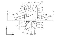
次にこの発明の第二実施形態について図10に基づいて説明する。なお、ここで、上記実施形態と同様の部材は同様の符号を付して説明を省略する。この実施形態の表皮材止着具52は、チャック部14の中心部には略矢印形状の収容部16が、側面14e,14fに貫通して形成されている。収容部16の開口方向は、内側面16aが側面14aと側面14cの間の角部の少し内側で、側面14aと側面14cに対して各々略45°に傾いて設けられている。収容部16の開口部17は、側面14aと側面14cの間の角部に連通し開口されている。つまり、表皮材46の係止用端部材50の差込方向は、側面14a,14cに対して略45°であり、プレート40の面方向であるY軸方向に対して45°である。従って、表皮材46の係止用端部材50の差込方向も、嵌合部20のプレート40の孔部49への差込方向に対して45°の角度で交差している。この実施形態では、チャック部14の、側面14aと側面14cが係止爪19となり、側面14bと側面14dの間の角部が係止爪基端部21となる。
Next, a second embodiment of the present invention will be described with reference to FIG. Here, the same members as those in the above embodiment are denoted by the same reference numerals, and the description thereof is omitted. In the skin material fastener 52 of this embodiment, a substantially arrow-shaped storage portion 16 is formed in the center portion of the chuck portion 14 so as to penetrate the side surfaces 14e and 14f. The opening direction of the accommodating portion 16 is provided such that the inner side surface 16a is slightly inside the corner portion between the side surface 14a and the side surface 14c and is inclined at approximately 45 ° with respect to the side surface 14a and the side surface 14c. The opening portion 17 of the housing portion 16 is open to communicate with a corner portion between the side surface 14a and the side surface 14c. That is, the insertion direction of the locking end member 50 of the skin material 46 is approximately 45 ° with respect to the side surfaces 14a and 14c, and 45 ° with respect to the Y-axis direction that is the surface direction of the plate 40. Accordingly, the insertion direction of the locking end member 50 of the skin material 46 also intersects with the insertion direction of the fitting portion 20 into the hole 49 of the plate 40 at an angle of 45 °. In this embodiment, the side surface 14 a and the side surface 14 c of the chuck portion 14 become the locking claw 19, and the corner portion between the side surface 14 b and the side surface 14 d becomes the locking claw base end portion 21.
この実施形態の表皮材止着具52によれば、表皮材46の係止用端部材50が、プレート40に対して45°の角度で取り付けられる場合にも、確実に係止用端部材50の側面50aが収容部16の内側面16aに当接し、45°の方向に引く力に抗して取り付け強度が高いものである。なお、収容部16の開口方向である、表皮材46の係止用端部材50の差込方向の角度は45°以外に、プレート40の面に対して90°未満の任意の角度でよく、75°以下、好ましくは60°以下の任意の角度に設定し得るものである。
According to the skin material fastening device 52 of this embodiment, even when the locking end member 50 of the skin material 46 is attached to the plate 40 at an angle of 45 °, the locking end member 50 is surely secured. The side surface 50a abuts against the inner side surface 16a of the accommodating portion 16, and the attachment strength is high against the force pulled in the 45 ° direction. The angle in the insertion direction of the locking end member 50 of the skin material 46, which is the opening direction of the housing portion 16, may be any angle other than 45 ° and less than 90 ° with respect to the surface of the plate 40, It can be set to an arbitrary angle of 75 ° or less, preferably 60 ° or less.
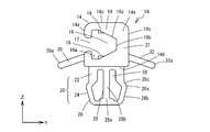
次にこの発明の第三実施形態について図11に基づいて説明する。なお、ここで、上記実施形態と同様の部材は同様の符号を付して説明を省略する。この実施形態の表皮材止着具54は、首部22から延長した弾性片26と支柱部28との間の空間から、首部22内に連通し、チャック部14側向かって形成された凹状部56が設けられたものである。凹状部56は、一対の弾性片26に対応して、支柱28の両側に各々形成されている。さらに、この実施形態では、首部22のZ軸方向の長さが、上記実施形態と比較して長く形成されている。
Next, a third embodiment of the present invention will be described with reference to FIG. Here, the same members as those in the above embodiment are denoted by the same reference numerals, and the description thereof is omitted. The skin material fastening device 54 of this embodiment communicates with the inside of the neck portion 22 from the space between the elastic piece 26 extended from the neck portion 22 and the column portion 28 and is formed toward the chuck portion 14 side. Is provided. The concave portions 56 are respectively formed on both sides of the support column 28 corresponding to the pair of elastic pieces 26. Furthermore, in this embodiment, the length of the neck portion 22 in the Z-axis direction is longer than that in the above embodiment.
この実施形態の表皮材止着具54によれば、首部22の内側に入り込んだ凹状部56が形成され、弾性片26がより撓みやすく形成されている。これにより、表皮材止着具54に大きな力がかからない用途では、弱い力で取り付け作業することができ、プレート40に対して容易に着脱することを可能にし、作業性も向上する。
According to the skin material fastener 54 of this embodiment, the recessed portion 56 that enters the inside of the neck portion 22 is formed, and the elastic piece 26 is formed more easily. Thereby, in an application in which a large force is not applied to the skin material fastener 54, the attachment work can be performed with a weak force, and it can be easily attached to and detached from the plate 40, and the workability is also improved.
なお、この発明の表皮材止着具は、上記各実施の形態に限定されるものではなく、細部形状や寸法等、適宜変更することができる。表皮材止着具の材質や表面の仕上げ、色彩等は自由に選択することができる。表皮材止着具のチャック部や弾性片のX軸方向の長さやは自由に変更可能であり、係止用端部材への取り付け強度や着脱作業の操作性によって適宜設定することができる。収容部の角度、つまり係止用端部材の差込角度は、プレートに対して平行又は45°以外に、上述のように75°以下の任意の角度に設定し得るものである。首部の断面形状は、正円や楕円、十字形状以外の形状でもよく、開口部の方向に係止用端部材に強い張力がかけられた時にプレートの孔部の内周面に当接する部分を有するものであれば良い。環状の弾性片の形状は、円形や多角形等、適宜設定し得るものである。また、この発明の表皮材止着具は、座席の座面以外に、背もたれや天井等、いろいろな部分に使用することができる。プレートの孔部の形状は円形以外でもよく、孔部の形状に合わせて嵌合部の形状を変更することで着脱可能となる。
It should be noted that the skin material fastening device of the present invention is not limited to the above-described embodiments, and the detailed shape, dimensions, and the like can be appropriately changed. The material, surface finish, color, etc. of the skin material fastener can be freely selected. The length in the X-axis direction of the chuck portion of the skin material fastener and the elastic piece can be freely changed, and can be set as appropriate depending on the attachment strength to the locking end member and the operability of the attachment / detachment work. The angle of the accommodating portion, that is, the insertion angle of the locking end member can be set to an arbitrary angle of 75 ° or less as described above, in addition to being parallel to the plate or 45 °. The cross-sectional shape of the neck may be a shape other than a perfect circle, ellipse, or cross shape, and the portion that contacts the inner peripheral surface of the plate hole when a strong tension is applied to the locking end member in the direction of the opening. What is necessary is just to have. The shape of the annular elastic piece can be appropriately set such as a circle or a polygon. Further, the skin material fastening device of the present invention can be used for various parts such as a backrest and a ceiling in addition to the seating surface of the seat. The shape of the hole portion of the plate may be other than a circle, and the plate portion can be detached by changing the shape of the fitting portion according to the shape of the hole portion.