WO2018151178A1 - Refrigerating device - Google Patents
Refrigerating device Download PDFInfo
- Publication number
- WO2018151178A1 WO2018151178A1 PCT/JP2018/005141 JP2018005141W WO2018151178A1 WO 2018151178 A1 WO2018151178 A1 WO 2018151178A1 JP 2018005141 W JP2018005141 W JP 2018005141W WO 2018151178 A1 WO2018151178 A1 WO 2018151178A1
- Authority
- WO
- WIPO (PCT)
- Prior art keywords
- refrigerant
- control
- unit
- temperature
- fusible plug
- Prior art date
Links
Images


Classifications
-
- F—MECHANICAL ENGINEERING; LIGHTING; HEATING; WEAPONS; BLASTING
- F25—REFRIGERATION OR COOLING; COMBINED HEATING AND REFRIGERATION SYSTEMS; HEAT PUMP SYSTEMS; MANUFACTURE OR STORAGE OF ICE; LIQUEFACTION SOLIDIFICATION OF GASES
- F25B—REFRIGERATION MACHINES, PLANTS OR SYSTEMS; COMBINED HEATING AND REFRIGERATION SYSTEMS; HEAT PUMP SYSTEMS
- F25B43/00—Arrangements for separating or purifying gases or liquids; Arrangements for vaporising the residuum of liquid refrigerant, e.g. by heat
- F25B43/006—Accumulators
-
- F—MECHANICAL ENGINEERING; LIGHTING; HEATING; WEAPONS; BLASTING
- F24—HEATING; RANGES; VENTILATING
- F24F—AIR-CONDITIONING; AIR-HUMIDIFICATION; VENTILATION; USE OF AIR CURRENTS FOR SCREENING
- F24F11/00—Control or safety arrangements
- F24F11/30—Control or safety arrangements for purposes related to the operation of the system, e.g. for safety or monitoring
- F24F11/32—Responding to malfunctions or emergencies
- F24F11/36—Responding to malfunctions or emergencies to leakage of heat-exchange fluid
-
- F—MECHANICAL ENGINEERING; LIGHTING; HEATING; WEAPONS; BLASTING
- F25—REFRIGERATION OR COOLING; COMBINED HEATING AND REFRIGERATION SYSTEMS; HEAT PUMP SYSTEMS; MANUFACTURE OR STORAGE OF ICE; LIQUEFACTION SOLIDIFICATION OF GASES
- F25B—REFRIGERATION MACHINES, PLANTS OR SYSTEMS; COMBINED HEATING AND REFRIGERATION SYSTEMS; HEAT PUMP SYSTEMS
- F25B1/00—Compression machines, plants or systems with non-reversible cycle
- F25B1/04—Compression machines, plants or systems with non-reversible cycle with compressor of rotary type
-
- F—MECHANICAL ENGINEERING; LIGHTING; HEATING; WEAPONS; BLASTING
- F25—REFRIGERATION OR COOLING; COMBINED HEATING AND REFRIGERATION SYSTEMS; HEAT PUMP SYSTEMS; MANUFACTURE OR STORAGE OF ICE; LIQUEFACTION SOLIDIFICATION OF GASES
- F25B—REFRIGERATION MACHINES, PLANTS OR SYSTEMS; COMBINED HEATING AND REFRIGERATION SYSTEMS; HEAT PUMP SYSTEMS
- F25B41/00—Fluid-circulation arrangements
- F25B41/20—Disposition of valves, e.g. of on-off valves or flow control valves
- F25B41/24—Arrangement of shut-off valves for disconnecting a part of the refrigerant cycle, e.g. an outdoor part
-
- F—MECHANICAL ENGINEERING; LIGHTING; HEATING; WEAPONS; BLASTING
- F25—REFRIGERATION OR COOLING; COMBINED HEATING AND REFRIGERATION SYSTEMS; HEAT PUMP SYSTEMS; MANUFACTURE OR STORAGE OF ICE; LIQUEFACTION SOLIDIFICATION OF GASES
- F25B—REFRIGERATION MACHINES, PLANTS OR SYSTEMS; COMBINED HEATING AND REFRIGERATION SYSTEMS; HEAT PUMP SYSTEMS
- F25B45/00—Arrangements for charging or discharging refrigerant
-
- F—MECHANICAL ENGINEERING; LIGHTING; HEATING; WEAPONS; BLASTING
- F25—REFRIGERATION OR COOLING; COMBINED HEATING AND REFRIGERATION SYSTEMS; HEAT PUMP SYSTEMS; MANUFACTURE OR STORAGE OF ICE; LIQUEFACTION SOLIDIFICATION OF GASES
- F25B—REFRIGERATION MACHINES, PLANTS OR SYSTEMS; COMBINED HEATING AND REFRIGERATION SYSTEMS; HEAT PUMP SYSTEMS
- F25B49/00—Arrangement or mounting of control or safety devices
- F25B49/02—Arrangement or mounting of control or safety devices for compression type machines, plants or systems
-
- F—MECHANICAL ENGINEERING; LIGHTING; HEATING; WEAPONS; BLASTING
- F25—REFRIGERATION OR COOLING; COMBINED HEATING AND REFRIGERATION SYSTEMS; HEAT PUMP SYSTEMS; MANUFACTURE OR STORAGE OF ICE; LIQUEFACTION SOLIDIFICATION OF GASES
- F25B—REFRIGERATION MACHINES, PLANTS OR SYSTEMS; COMBINED HEATING AND REFRIGERATION SYSTEMS; HEAT PUMP SYSTEMS
- F25B2400/00—General features or devices for refrigeration machines, plants or systems, combined heating and refrigeration systems or heat-pump systems, i.e. not limited to a particular subgroup of F25B
- F25B2400/04—Refrigeration circuit bypassing means
-
- F—MECHANICAL ENGINEERING; LIGHTING; HEATING; WEAPONS; BLASTING
- F25—REFRIGERATION OR COOLING; COMBINED HEATING AND REFRIGERATION SYSTEMS; HEAT PUMP SYSTEMS; MANUFACTURE OR STORAGE OF ICE; LIQUEFACTION SOLIDIFICATION OF GASES
- F25B—REFRIGERATION MACHINES, PLANTS OR SYSTEMS; COMBINED HEATING AND REFRIGERATION SYSTEMS; HEAT PUMP SYSTEMS
- F25B2400/00—General features or devices for refrigeration machines, plants or systems, combined heating and refrigeration systems or heat-pump systems, i.e. not limited to a particular subgroup of F25B
- F25B2400/19—Pumping down refrigerant from one part of the cycle to another part of the cycle, e.g. when the cycle is changed from cooling to heating, or before a defrost cycle is started
-
- F—MECHANICAL ENGINEERING; LIGHTING; HEATING; WEAPONS; BLASTING
- F25—REFRIGERATION OR COOLING; COMBINED HEATING AND REFRIGERATION SYSTEMS; HEAT PUMP SYSTEMS; MANUFACTURE OR STORAGE OF ICE; LIQUEFACTION SOLIDIFICATION OF GASES
- F25B—REFRIGERATION MACHINES, PLANTS OR SYSTEMS; COMBINED HEATING AND REFRIGERATION SYSTEMS; HEAT PUMP SYSTEMS
- F25B2500/00—Problems to be solved
- F25B2500/22—Preventing, detecting or repairing leaks of refrigeration fluids
- F25B2500/221—Preventing leaks from developing
Definitions
- the present invention relates to a refrigeration apparatus.
- Patent Document 1 Japanese Patent Laid-Open No. 5-118720
- opening control of a predetermined control valve such as an electromagnetic valve or an electric valve
- Control the valve to the minimum opening (closed state) preventing the flow of refrigerant to the use unit side, and the use side space where the use unit is installed (such as a living space or a storage space where people enter and exit)
- a method for suppressing further leakage of the refrigerant There has been proposed a method for suppressing further leakage of the refrigerant.
- control valves such as electromagnetic valves and motor-operated valves have a characteristic that the flow of the refrigerant cannot be completely blocked even if controlled to the minimum opening (closed state). In other words, even when the control valve is controlled to the minimum opening, a minute refrigerant flow path (micro flow path) is formed, and a small amount of refrigerant is allowed to pass through.
- Patent Document 1 even if the control valve is controlled to the minimum opening degree at the time of refrigerant leakage, a small amount of refrigerant passing through the control valve flows to the usage unit side and leaks in the usage side space. There is a concern that the refrigerant may stay.
- the use side space is a highly airtight space such as the space in the prefabricated storage, and in such a case, when a refrigerant leak occurs in the use side unit, the patent document When method 1 is used, there is a particular concern that the concentration of the leaked refrigerant increases in the use side space. That is, according to Patent Document 1, a case is assumed in which the security against refrigerant leakage cannot be reliably ensured.
- a refrigeration apparatus is a refrigeration apparatus that includes a refrigerant circuit including a use side circuit and performs a refrigeration cycle in the refrigerant circuit, and includes a compressor, a first control valve, and a refrigerant discharge mechanism.
- the compressor is disposed in the refrigerant circuit.
- the compressor compresses the refrigerant.
- a 1st control valve is arrange
- the first control valve is closed by being controlled to the minimum opening. The closed state is the state that most hinders the flow of the refrigerant to the use side circuit.
- the refrigerant discharge mechanism is disposed in the refrigerant circuit.
- release mechanism makes a refrigerant circuit communicate with external space by being in an open state.
- the control unit controls the state of each device.
- the refrigerant leakage detection unit detects refrigerant leakage in the utilization side circuit by detecting the state of the refrigerant in the utilization side circuit or the refrigerant flowing out of the utilization side circuit.
- a control part performs 1st control and 2nd control, when the refrigerant
- a control part makes a refrigerant
- the control unit In 1 control, a 1st control valve is controlled to a closed state.
- the refrigerant leakage detection unit detects the refrigerant leakage, and the control unit controls the first control valve disposed on the upstream side of the refrigerant flow in the use side circuit to be closed. The As a result, the refrigerant flow to the use side circuit is hindered when the refrigerant leaks.
- the control unit shifts the refrigerant discharge mechanism to the open state in the second control.
- the refrigerant discharge mechanism is controlled to be in the open state.
- the refrigerant discharge mechanism is opened, and the refrigerant in the refrigerant circuit is released outside the refrigerant circuit via the refrigerant discharge mechanism. For this reason, the flow of the refrigerant to the use side circuit is further hindered.
- refrigerant here is not particularly limited, but for example, a slightly flammable refrigerant such as R32, CO 2 or the like is assumed.
- the “refrigerant leakage detection unit” here is a refrigerant leakage sensor that directly detects refrigerant leaked from the refrigerant circuit (leakage refrigerant), or a pressure that detects the state (pressure or temperature) of the refrigerant in the refrigerant circuit.
- a sensor or a temperature sensor is a refrigerant leakage sensor that directly detects refrigerant leaked from the refrigerant circuit (leakage refrigerant), or a pressure that detects the state (pressure or temperature) of the refrigerant in the refrigerant circuit.
- first control valve here is not particularly limited as long as it is a valve capable of opening degree control, and is, for example, an electromagnetic valve or an electric valve.
- the “refrigerant release mechanism” here is a mechanism that causes the refrigerant circuit to communicate with the external space by being in an open state, and is opened when a refrigerant leak in the user side circuit is detected by the refrigerant leak detector.
- the mechanism is not particularly limited as long as it is a mechanism that can be shifted to a state, and is, for example, a fusible plug, an electromagnetic valve, an electric valve (electronic expansion valve), or the like.
- the refrigeration apparatus is the refrigeration apparatus according to the first aspect, and further includes a heating unit.
- the refrigerant discharge mechanism is a fusible plug that is heated to a predetermined first temperature or higher and melts to be opened.
- the heating unit heats the fusible plug directly or indirectly.
- the control unit heats the fusible plug to the first temperature by the heating unit.
- the heating unit is controlled to heat the fusible plug to the first temperature.
- the fusible plug is opened, and the refrigerant in the refrigerant circuit is discharged out of the refrigerant circuit through the fusible plug. For this reason, the flow of the refrigerant to the use side circuit is further hindered.
- the “heating unit” is not particularly limited as long as it is a means for heating the fusible plug, and is, for example, a refrigerant pipe or an electric heater through which a hot gas refrigerant for heating the fusible plug flows.
- the refrigeration apparatus is the refrigeration apparatus according to the second aspect, and further includes a high-pressure refrigerant pipe and a second control valve.
- the high-pressure refrigerant pipe is a pipe through which a high-pressure hot gas refrigerant discharged from the compressor flows.
- the second control valve causes the compressor and the high-pressure refrigerant pipe to communicate with each other by being in the first state.
- the control unit drives the compressor, controls the second control valve to the first state, and causes the high-pressure refrigerant pipe to function as a heating unit.
- the refrigerant piping high-pressure refrigerant piping
- the heating unit can be configured with a simple configuration. Therefore, versatility is improved and cost increase is suppressed.
- the refrigeration apparatus is the refrigeration apparatus according to the second aspect or the third aspect, and further includes an electric heater.
- the electric heater is heated when energized.
- the heating state is a state in which heat is generated.
- the control unit controls the electric heater to a heating state and functions as a heating unit.
- the heating unit can be configured with a simple configuration. Therefore, versatility is improved and cost increase is suppressed.
- the refrigeration apparatus is the refrigeration apparatus according to any one of the second aspect to the fourth aspect, and further includes a heating temperature detection unit.
- the heating temperature detection unit detects the temperature of the heating unit.
- the control unit controls the state of the heating unit based on the detection value of the heating temperature detection unit.
- the state of the heating unit is controlled according to the detection value in the heating temperature detection unit.
- the heating unit can be controlled to the target temperature according to the situation, and the fusible plug can be accurately raised to the first temperature. Therefore, security is further improved.
- the refrigeration apparatus is the refrigeration apparatus according to any of the second to fifth aspects, and further includes a fusible plug temperature detection unit and an output unit.
- the fusible plug temperature detector detects the temperature of the fusible plug.
- the output unit outputs predetermined notification information.
- the control unit Broadcast information is output.
- the second temperature is a value lower than the first temperature.
- the refrigeration apparatus is the refrigeration apparatus according to any one of the second to fifth aspects, and further includes a fusible plug temperature detection unit.
- the fusible plug temperature detector detects the temperature of the fusible plug.
- the control unit detects the third control when the fusible plug temperature detection unit detects that the temperature of the soluble plug is equal to or higher than the second temperature. Execute.
- the second temperature is a value lower than the first temperature.
- the control unit controls the state of each device to prevent the fusible plug from becoming the first temperature or higher.
- the refrigeration apparatus is the refrigeration apparatus according to any one of the second aspect to the fifth aspect, and further includes a fusible plug temperature detection unit and a third control valve.
- the fusible plug temperature detector detects the temperature of the fusible plug.
- the third control valve is disposed in the refrigerant circuit. The third control valve controls the flow rate of the refrigerant flowing to the fusible plug according to the opening degree.
- the control unit detects the third control when the fusible plug temperature detection unit detects that the temperature of the soluble plug is equal to or higher than the second temperature. Control the valve to the minimum opening.
- the second temperature is a value lower than the first temperature.
- the refrigeration apparatus is the refrigeration apparatus according to any one of the first to eighth aspects, and further includes a heat exchanger and a blower.
- the blower generates an air flow.
- the heat exchanger is disposed between the discharge pipe of the compressor and the refrigerant discharge mechanism in the refrigerant circuit.
- the heat exchanger functions as a refrigerant radiator by exchanging heat between the refrigerant and the air flow.
- the control unit stops the blower in the second control.
- the blower is stopped, and heat dissipation or condensation of the refrigerant in the heat exchanger is suppressed.
- the high-pressure hot gas refrigerant can be supplied to the high-pressure refrigerant pipe in a shorter time, and the refrigerant discharge mechanism can be quickly raised to the first temperature. Therefore, security is further improved.
- the refrigeration apparatus is the refrigeration apparatus according to any one of the first aspect to the ninth aspect, and further includes a second blower.
- the second blower generates a second air flow.
- the second air flow is an air flow that is blown out from the space where the refrigerant discharge mechanism is disposed to the external space.
- the control unit drives the second blower after the completion of the second control.
- the second blower is driven and a second air flow is generated.
- the refrigerant flowing out from the refrigerant release mechanism is released to the external space. Therefore, in the space where the refrigerant discharge mechanism is arranged, the concentration of the refrigerant flowing out of the refrigerant discharge mechanism is suppressed from becoming a dangerous value. Therefore, security is further improved.
- the refrigeration apparatus according to the eleventh aspect of the present disclosure is the refrigeration apparatus according to any one of the first to tenth aspects, and the control unit executes the second control after the completion of the first control.
- the first control valve is controlled to be in the closed state, so that the refrigerant leakage in the usage-side space is suppressed, and before the refrigerant discharge mechanism is controlled to the open state (refrigerant Before being discharged out of the refrigerant circuit).
- the refrigerant recovery operation for recovering the refrigerant in a predetermined container can be performed before the refrigerant discharge mechanism is controlled to be in the open state.
- refrigerant leakage detection unit when refrigerant leakage is detected by the refrigerant leakage detection unit, before the refrigerant is released out of the refrigerant circuit, output of notification information to the administrator or whether there is a false detection in the refrigerant leakage detection unit. It becomes possible to judge.
- refrigerant leakage when refrigerant leakage is detected by the refrigerant leakage detection unit, it is possible to ensure a time delay for confirming whether or not there is a false detection regarding the detected refrigerant leakage before the refrigerant is released out of the refrigerant circuit. It has become. Therefore, convenience can be improved.
- the refrigeration apparatus is the refrigeration apparatus according to any one of the first aspect to the eleventh aspect, and further includes a refrigerant container.
- the refrigerant container is disposed in the refrigerant circuit.
- the refrigerant container contains the refrigerant.
- the control unit drives the compressor and causes the refrigerant container to collect the refrigerant.
- the refrigeration apparatus is the refrigeration apparatus according to any one of the first aspect to the twelfth aspect, and the control unit, after execution of the first control, has passed the first time, The second control is executed.
- the first time is a time calculated based on the amount of refrigerant passing through the first control valve in the closed state according to the characteristics of the first control valve.
- the first time is a time required for the refrigerant concentration to reach a predetermined value in the use side space where the use side circuit is arranged.
- the second control is executed after the first time has elapsed after the first control valve is controlled to be closed.
- the release of the refrigerant to the outside of the refrigerant circuit via the refrigerant discharge mechanism may be delayed until the refrigerant concentration in the use side space reaches a dangerous value (predetermined value). It becomes possible. That is, when a refrigerant leak occurs, a predetermined process is performed without discharging the refrigerant out of the refrigerant circuit via the refrigerant discharge mechanism until the first time that can ensure the safety has elapsed. It becomes possible.
- the refrigerant leak detection unit it is possible to perform a refrigerant recovery operation in which the refrigerant is recovered in a predetermined container before the first time has elapsed (that is, before the refrigerant discharge mechanism is controlled to be opened). Further, when the refrigerant leak is detected by the refrigerant leak detection unit, the notification information is output to the administrator or the refrigerant leaks before the first time has elapsed (that is, before the refrigerant is released outside the refrigerant circuit). It is possible to determine whether or not there is a false detection in the detection unit.
- refrigerant leakage detection unit when refrigerant leakage is detected by the refrigerant leakage detection unit, it is possible to ensure a time delay for confirming whether or not there is a false detection regarding the detected refrigerant leakage before the refrigerant is released out of the refrigerant circuit. It has become.
- the “predetermined value” here is appropriately set according to the type of refrigerant enclosed in the refrigerant circuit, the design specifications, the installation environment, and the like.
- the “predetermined value” is set to a value corresponding to one-fourth of the lower limit of combustion (LFL) or the oxygen deficiency tolerance.
- the refrigeration apparatus is the refrigeration apparatus according to any one of the first to thirteenth aspects, and the refrigerant leakage detection unit detects the concentration of refrigerant leaking from the use side circuit.
- the refrigerant leakage detection unit outputs a detection signal to the control unit.
- a detection signal is a signal which specifies the density
- the control unit executes the first control when the concentration of the refrigerant based on the detection signal is equal to or higher than the first reference value.
- the control unit executes the second control when the concentration of the refrigerant based on the detection signal is equal to or higher than the second reference value.
- the second reference value is larger than the first reference value.
- the first control and the second control step by step according to the concentration of the leaked refrigerant detected by the refrigerant leak detection unit. That is, when the refrigerant concentration detected by the refrigerant leakage detection unit is a low risk value (first reference value), the first control is executed to control the first control valve to be closed. The second control is not executed while suppressing further refrigerant leakage in the use-side space, so that the refrigerant is released from the refrigerant circuit via the refrigerant discharge mechanism.
- the refrigerant is discharged by executing the second control in addition to the first control.
- the refrigerant is discharged out of the refrigerant circuit through the mechanism.
- the cost associated with the recovery work and post-processing is related to the fact that the second control is executed when the necessity is small while the safety is ensured when the refrigerant leaks, and the refrigerant is discharged out of the refrigerant circuit. Is suppressed from increasing.
- the first reference value and the second reference value are set as appropriate according to the type of refrigerant enclosed in the refrigerant circuit, design specifications, installation environment, and the like.
- the first reference value is set to a value that assumes that a leaked refrigerant has occurred.
- the second reference value is set to a value corresponding to one-fourth of the lower combustion limit concentration (LFL) or the oxygen deficiency tolerance.
- the refrigeration apparatus is the refrigeration apparatus according to any one of the first aspect to the fourteenth aspect, and further includes a refrigerant state sensor and an erroneous detection determination unit.
- the refrigerant state sensor detects the state of the refrigerant in the refrigerant circuit.
- the erroneous detection determination unit determines whether there is an erroneous detection of refrigerant leakage in the refrigerant leakage detection unit based on the detection value of the refrigerant state sensor.
- a control part performs 2nd control, when it is judged that there is no false detection by the false detection judgment part.
- the refrigeration apparatus is the refrigeration apparatus according to any one of the first to fifteenth aspects, and the refrigerant circuit includes a plurality of usage-side circuits.
- a refrigerant discharge mechanism and a plurality of first control valves are arranged on the upstream side of the refrigerant flow of each use side circuit.
- the amount of refrigerant to be enclosed is large and the amount of refrigerant leakage at the time of refrigerant leakage can be particularly large compared to a refrigerant circuit including a single usage-side circuit. Further, there is a greater risk that the refrigerant concentration in the use side space becomes a dangerous value, and there is a greater demand for ensuring safety.
- two or more first control valves that prevent the flow of the refrigerant to the use side refrigerant circuit are arranged upstream of the refrigerant flow of each use side circuit. Security at the time is more reliably secured. In particular, when refrigerant leakage occurs, even if the user-side space is left in a sealed state for a long period, the concentration of the leaked refrigerant in the user-side space is suppressed to a dangerous concentration. .
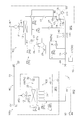
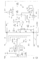
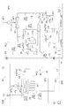
- FIG. 1 is a schematic configuration diagram of a refrigeration apparatus according to an embodiment of the present disclosure.
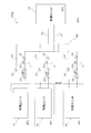
- the block diagram which showed roughly the controller and each part connected to a controller.
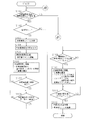
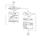
- the flowchart which showed an example of the flow of a process of a controller.
- the flowchart which showed an example of the flow of a process of a controller.
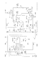
- the schematic block diagram of the freezing apparatus which concerns on the modification 1.
- FIG. The schematic block diagram of the other freezing apparatus which concerns on the modification 1.
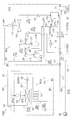
- FIG. The schematic block diagram of the freezing apparatus which concerns on the modification 2.
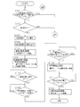
- FIG. 10 is a flowchart showing an example of a processing flow of a controller in a refrigeration apparatus according to Modification 3.
- FIG. 4 The schematic block diagram of the other freezing apparatus which concerns on the modification 4.
- FIG. 5. The schematic block diagram of the freezing apparatus which concerns on the modification 5.
- FIG. 1 The schematic block diagram of the other freezing apparatus which concerns on the modification 4.
- FIG. 1 is a schematic configuration diagram of a refrigeration apparatus 100 according to an embodiment of the present disclosure.
- the refrigeration apparatus 100 is a low-temperature refrigeration apparatus that cools the use-side space SP1 such as in a prefabricated storage, in a low-temperature warehouse, in a transport container, or in a store showcase by a vapor compression refrigeration cycle.
- the refrigeration apparatus 100 mainly includes a heat source unit 10, a use unit 30, a liquid side connection pipe L1 and a gas side connection pipe G1, a refrigerant leak sensor 40 that detects refrigerant leak in the use unit 30, an input device, and a display.
- a remote controller 50 as an apparatus and a controller 60 that controls the operation of the refrigeration apparatus 100 are provided.
- the refrigerant circuit RC is configured by connecting the heat source unit 10 and the utilization unit 30 via the liquid side communication pipe L1 and the gas side communication pipe G1.
- a refrigeration cycle is performed in which the refrigerant is compressed, cooled or condensed, decompressed, heated or evaporated, and then compressed again in the refrigerant circuit RC.
- the refrigerant circuit RC is filled with slightly flammable R32 as a refrigerant for performing a vapor compression refrigeration cycle.
- Heat source unit 10 The heat source unit 10 is connected to the utilization unit 30 via the liquid side communication pipe L1 and the gas side communication pipe G1, and constitutes a part of the refrigerant circuit RC (heat source side refrigerant circuit RC1).
- the heat source unit 10 includes a plurality of refrigerant pipes Pa, a compressor 11, a heat source side heat exchanger 12, a receiver 13, a supercooler 14, and a heat source side expansion valve as devices constituting the heat source side refrigerant circuit RC1.
- the refrigerant pipe Pa disposed in the heat source unit 10 includes a first gas side refrigerant pipe P1 that connects the discharge side of the compressor 11 and the gas side inlet / outlet of the heat source side heat exchanger 12.
- the first gas side refrigerant pipe P1 corresponds to a discharge pipe of the compressor 11 (a pipe through which a high-pressure hot gas refrigerant discharged from the compressor flows).
- the first gas side refrigerant pipe P1 includes a branch pipe P1 ′ branched between both ends, and is connected to the hot gas bypass valve 17 in the branch pipe P1 ′.
- the refrigerant pipe Pa includes a liquid side refrigerant pipe P2 that connects the liquid side inlet / outlet of the heat source side heat exchanger 12 and the liquid side shut-off valve 24.
- the refrigerant pipe Pa includes a second gas side refrigerant pipe P3 that connects the suction side of the compressor 11 and the gas side shut-off valve 23.
- the second gas side refrigerant pipe P ⁇ b> 3 corresponds to the suction pipe of the compressor 11.
- the refrigerant pipe Pa includes an injection pipe P4 that branches a part of the refrigerant flowing through the liquid side refrigerant pipe P2 and returns it to the compressor 11.
- the injection pipe P4 is branched from a portion of the liquid side refrigerant pipe P2 on the downstream side of the supercooler 14, and after passing through the supercooler 14, is connected in the middle of the compression stroke of the compressor 11.
- the refrigerant pipe Pa is a hot gas pipe P5 (corresponding to a “high pressure refrigerant pipe” described in the claims) that bypasses the high-pressure hot gas refrigerant (hot gas) discharged from the compressor 11 to a predetermined bypass destination. )It is included.
- one end of the hot gas pipe P5 is connected to the hot gas bypass valve 17 disposed in the first gas side refrigerant pipe P1, and the other end is upstream of the refrigerant flow of the receiver 13 of the liquid side refrigerant pipe P2. (More specifically, a portion between the first check valve 19 and the receiver 13).
- the refrigerant pipe Pa includes a bypass pipe P6 that bypasses the refrigerant that has passed through the heat source side expansion valve 15 to the receiver 13.
- One end of the hot gas pipe P5 is a downstream part of the refrigerant flow of the heat source side expansion valve 15 of the liquid side refrigerant pipe P2 (more specifically, a part between the liquid side closing valve 24 and the heat source side expansion valve 15). It is connected to the.
- the other end of the hot gas pipe P5 is connected to the upstream side portion of the refrigerant flow of the receiver 13 of the liquid side refrigerant pipe P2 (more specifically, the portion between the first check valve 19 and the receiver 13). ing.
- the refrigerant pipe Pa includes a fusible plug installation pipe P7 connected to the receiver 13.
- One end of the fusible plug installation pipe P7 is connected to a bypass port 13c (described later) of the receiver 13, and the other end is connected to the fusible plug 22.
- the fusible plug installation pipe P7 includes a main pipe in which the backup valve 18 is disposed, and a branch pipe that connects a portion closer to the receiver 13 and a portion closer to the fusible plug 22 than the backup valve 18. Contains.
- a third check valve 21 is arranged in the branch pipe of the fusible plug installation pipe P7.
- the fusible plug 22 is connected to the main pipe of the fusible plug installation pipe P7.
- coolant piping Pa may actually be comprised by single piping, and may be comprised by connecting with several piping via a joint etc.
- the compressor 11 is a device that compresses a low-pressure refrigerant in the refrigeration cycle until it reaches a high pressure.
- the compressor 11 has a hermetic structure in which a displacement type compression element (not shown) such as a rotary type or a scroll type is rotationally driven by a compressor motor (not shown).
- the compressor motor can control the operation frequency by an inverter, and thus the capacity of the compressor 11 can be controlled.
- the heat source side heat exchanger 12 (corresponding to the “heat exchanger” described in the claims) is a heat exchanger that functions as a condenser (or radiator) for high-pressure refrigerant in the refrigeration cycle.
- the heat source side heat exchanger 12 includes a plurality of heat transfer tubes and heat transfer fins (not shown).
- the heat source side heat exchanger 12 is configured such that heat exchange is performed between the refrigerant in the heat transfer tube and the air passing through the periphery of the heat transfer tube or the heat transfer fin (a heat source side air flow AF1 described later). ing.
- the heat source side heat exchanger 12 is disposed between the discharge side (first gas side refrigerant pipe P1) of the compressor 11 and the liquid side refrigerant pipe P2. In other words, it can be said that the heat source side heat exchanger 12 is disposed between the discharge pipe of the compressor 11 and the fusible plug 22.
- the receiver 13 (corresponding to the “refrigerant container” described in the claims) is a container that temporarily stores the refrigerant condensed in the heat source side heat exchanger 12, and is disposed in the liquid side refrigerant pipe P2.
- the receiver 13 has a capacity that can accommodate surplus refrigerant according to the amount of refrigerant charged in the refrigerant circuit RC.
- the refrigerant flows into the receiver 13 from the inlet 13a and flows out from the outlet 13b. Further, a bypass port 13c is formed in the receiver 13, and a fusible plug installation pipe P7 is connected to the bypass port 13c.
- the supercooler 14 is a heat exchanger that further cools the refrigerant temporarily stored in the receiver 13, and is disposed in the downstream portion of the receiver 13 in the liquid side refrigerant pipe P ⁇ b> 2.
- the subcooler 14 includes a first flow path 141 through which the refrigerant flowing through the liquid side refrigerant pipe P2 passes, and a second flow path 142 through which the refrigerant flowing through the injection pipe P4 passes.
- the refrigerant flowing through the channel 141 and the second channel 142 is configured to perform heat exchange.
- the heat source side expansion valve 15 (corresponding to the “first control valve” recited in the claims) is an electric expansion valve capable of opening degree control, and is a downstream portion of the subcooler 14 of the liquid side refrigerant pipe P2. Is arranged.
- the heat source side expansion valve 15 is in a closed state (a state in which the flow of the refrigerant to the downstream circuit is most hindered) by being controlled to the minimum opening.
- the heat source side expansion valve 15 is arranged on the upstream side of the refrigerant flow in the use side refrigerant circuit RC2 described later.
- the injection valve 16 is disposed in a portion of the injection pipe P4 up to the inlet of the supercooler 14.
- the injection valve 16 is an electric expansion valve whose opening degree can be controlled.
- the injection valve 16 depressurizes the refrigerant flowing upstream of the inlet / outlet of the supercooler 14 (second flow path 142) in the injection pipe P4 according to the opening degree.
- the supercooler 14 cools the refrigerant temporarily stored in the receiver 13 using the refrigerant branched from the liquid side refrigerant pipe P2 through the injection pipe P4 as a cooling source.
- the hot gas bypass valve 17 is an electric expansion valve whose opening degree can be controlled.
- the hot gas bypass valve 17 adjusts the flow rate of the refrigerant passing through the hot gas pipe P5 according to the opening degree.
- the backup valve 18 (corresponding to the “third control valve” recited in the claims) is a valve that controls the flow rate of the refrigerant flowing to the fusible plug 22 in accordance with the opening degree.
- the backup valve 18 is an electromagnetic valve capable of switching between a fully open state and a fully closed state by switching the drive voltage.
- the backup valve 18 is disposed on the fusible plug installation pipe P7 (main pipe). When the backup valve 18 is opened, the refrigerant is sent from the receiver 13 to the fusible plug 22.
- the first check valve 19 is arranged in the liquid side refrigerant pipe P2. More specifically, the first check valve 19 is arranged on the refrigerant flow upstream side of the receiver 13 on the outlet side of the heat source side heat exchanger 12. The first check valve 19 allows the refrigerant flow from the outlet side of the heat source side heat exchanger 12 and blocks the refrigerant flow from the receiver 13 side.
- the second check valve 20 is disposed in the bypass pipe P6.
- the second check valve 20 allows the refrigerant flow from one end side (the heat source side expansion valve 15 side) and blocks the refrigerant flow from the other end side (receiver 13 side).
- the third check valve 21 is disposed on the fusible plug installation pipe P7 (branch pipe).
- the third check valve 21 allows the flow of the refrigerant from one end side (portion on the fusible plug 22 side from the backup valve 18), and the refrigerant from the other end side (portion on the receiver 13 side from the backup valve 18). Cut off the flow.
- the fusible plug 22 is a known plug (melting plug generally used as a safety device such as a pressure vessel) that melts when heated.
- the fusible plug 22 is a screw-like component having a through hole filled with a low melting point metal.
- the material of the low melting point metal is not particularly limited, but for example, an alloy composed of 63.5% by mass of indium, 35% by mass of bismuth, 0.5% by mass of tin, and 1.0% of antimony is used.
- the fusible plug 22 is disposed in the receiver 13.
- the refrigerant circuit RC communicates with the external space, and the refrigerant in the receiver 13 flows out of the refrigerant circuit RC from the fusible plug 22 through the fusible plug installation pipe P7. That is, when the fusible plug 22 is opened, the refrigerant in the refrigerant circuit RC is released to the outside.
- the operating temperature of the fusible plug 22 (the first temperature Te1 at which the low melting point metal melts) is a value that is greater than the maximum temperature of the refrigerant in the receiver 13 that is assumed during normal operation and when the operation is stopped. And is set to a value equal to or lower than the discharge temperature of the compressor 11 at a predetermined refrigerant circulation rate. That is, in this embodiment, when the hot gas discharged from the compressor 11 is bypassed by the receiver 13, the fusible plug 22 can be in an open state.
- the refrigerant circuit RC is provided with a filter (not shown) for capturing the molten low melting point metal when the fusible plug 22 is opened.
- the gas side shut-off valve 23 is a manual valve disposed at a connection portion between the second gas side refrigerant pipe P3 and the gas side communication pipe G1.
- the gas side shut-off valve 23 has one end connected to the second gas side refrigerant pipe P3 and the other end connected to the gas side communication pipe G1.
- the liquid side shut-off valve 24 is a manual valve disposed at a connection portion between the liquid side refrigerant pipe P2 and the liquid side communication pipe L1.
- the liquid side shut-off valve 24 has one end connected to the liquid side refrigerant pipe P2 and the other end connected to the liquid side communication pipe L1.
- the heat source unit 10 includes a heat source side fan F1 that generates a heat source side air flow AF1 that passes through the heat source side heat exchanger 12 in the heat source side space SP2 (referred to as “fan” and “second fan” in the claims). Equivalent).
- the heat source side fan F ⁇ b> 1 is a blower that supplies the heat source side air flow AF ⁇ b> 1 as a cooling source of the refrigerant flowing through the heat source side heat exchanger 12 to the heat source side heat exchanger 12.
- the heat source side air flow AF1 (corresponding to “air flow” and “second air flow” described in the claims) is from the space outside the use side space SP1 (external space SP3) to the internal space (heat source side) of the heat source unit 10.
- the air flow flows into the external space SP3 after flowing into the space SP2) and passing through the heat source side heat exchanger 12.
- the heat source side air flow AF1 is an air flow blown from the heat source side space SP2 in which the fusible plug 22 is disposed to the external space SP3.
- the heat source side fan F1 includes a heat source side fan motor (not shown) as a drive source, and the start and stop and the number of rotations are appropriately controlled according to the situation.
- various sensors for detecting the state (mainly pressure or temperature) of the refrigerant in the refrigerant circuit RC are arranged.
- a suction pressure sensor 25 that detects a suction pressure LP that is a refrigerant pressure on the suction side of the compressor 11, and a discharge that is a refrigerant pressure on the discharge side of the compressor 11.
- a discharge pressure sensor 26 that detects the pressure HP is disposed.
- the suction pressure sensor 25 (corresponding to “refrigerant state sensor” described in claims) is connected to a second gas side refrigerant pipe P3 corresponding to the suction pipe of the compressor 11.
- the discharge pressure sensor 26 is connected to a first gas side refrigerant pipe P1 corresponding to the discharge pipe of the compressor 11.
- the heat source unit 10 is provided with a plurality of temperature sensors such as thermistors and thermocouples.
- a discharge temperature sensor 27a that detects a discharge temperature HT, which is the temperature of the refrigerant discharged from the compressor 11, is disposed in the discharge pipe (first gas side refrigerant pipe P1) of the compressor 11.
- the receiver 13 is provided with a receiver temperature sensor 27b that detects a receiver temperature RT that is the temperature of the refrigerant in the receiver 13.
- the fusible plug 22 (or the vicinity thereof) has a fusible plug temperature sensor 27c for detecting the fusible plug temperature PT which is the temperature of the fusible plug 22 (“soluble plug temperature described in the claims”). Corresponding to “detection unit”).
- a liquid level detection sensor 28 is disposed in the receiver 13.
- the liquid level detection sensor 28 detects a liquid level height HL that is the height of the liquid level of the liquid refrigerant accommodated in the receiver 13.
- the heat source unit 10 has a heat source unit controller C1 that controls the operation / state of each device included in the heat source unit 10.
- the heat source unit controller C1 includes a microcomputer including a CPU and a memory.
- the heat source unit controller C1 is electrically connected to each actuator (11, 15-18, F1) and various sensors (25-28) included in the heat source unit 10, and inputs and outputs signals to and from each other.
- the heat source unit control unit C1 is connected to a use unit control unit C2 (described later) of each use unit 30 and a remote controller 50 via a communication line cb1, and individually transmits and receives control signals and the like.
- the utilization unit 30 is connected to the heat source unit 10 via the liquid side communication pipe L1 and the gas side communication pipe G1.
- the usage unit 30 is disposed in the usage side space SP1 and constitutes a part of the refrigerant circuit RC (use side refrigerant circuit RC2). That is, the use side refrigerant circuit RC2 (corresponding to “use side circuit” described in claims) is arranged in the use side space SP1.
- the usage unit 30 includes a plurality of refrigerant pipes Pb, a usage side expansion valve 32, a usage side heat exchanger 33, and a drain pan 34.
- the refrigerant pipe Pb arranged in the usage unit 30 includes a first liquid side refrigerant pipe P8 that connects the liquid side communication pipe L1 and the usage side expansion valve 32.
- the first liquid side refrigerant pipe P8 includes a heating pipe 31 that is a refrigerant pipe through which the high-pressure liquid refrigerant sent from the heat source unit 10 passes.
- the heating pipe 31 is a pipe for melting ice blocks generated by freezing of drain water in the drain pan 34 and is thermally connected to the drain pan 34.
- the refrigerant pipe Pb includes a second liquid side refrigerant pipe P9 that connects the liquid side inlet / outlet of the usage side heat exchanger 33 and the usage side expansion valve 32.
- the refrigerant pipe Pb includes a gas side refrigerant pipe P10 that connects the gas side inlet / outlet of the use side heat exchanger 33 and the gas side communication pipe G1.
- coolant piping Pb (P8-P10) may actually be comprised by single piping, and may be comprised by connecting with several piping via a joint etc.
- the use side expansion valve 32 is a throttle mechanism that functions as a decompression means (expansion means) for the high-pressure refrigerant sent from the heat source unit 10.
- the use side expansion valve 32 depressurizes the refrigerant passing therethrough according to the opening degree.
- the use side expansion valve 32 is a mechanical expansion valve, and a known general-purpose product is used.
- the use-side expansion valve 32 communicates the valve main body including a valve body, a diaphragm, and the like, a temperature sensing cylinder filled with a refrigerant of the same type as the refrigerant flowing in the refrigerant circuit RC, and the valve main body and the temperature sensing cylinder.
- a temperature-sensitive expansion valve including a capillary tube.
- the use side expansion valve 32 has one end connected to the first liquid side refrigerant pipe P8 and the other end connected to the second liquid side refrigerant pipe P9.
- the use-side heat exchanger 33 is a heat exchanger that functions as a low-pressure refrigerant evaporator in the refrigeration cycle.
- the usage-side heat exchanger 33 is disposed in the usage-side space SP1 (inside the warehouse) and is a heat exchanger for cooling the internal air in the usage-side space SP1.
- the use side heat exchanger 33 includes a plurality of heat transfer tubes and heat transfer fins (not shown).
- the use side heat exchanger 33 is configured such that heat exchange is performed between the refrigerant in the heat transfer tube and the air passing around the heat transfer tubes or the heat transfer fins.
- the drain pan 34 receives and collects drain water generated in the use side heat exchanger 33.
- the drain pan 34 is disposed below the use side heat exchanger 33.
- the utilization unit 30 draws in air in the utilization side space SP1 (internal air), passes through the utilization side heat exchanger 33 and exchanges heat with the refrigerant, and then sends it to the utilization side space SP1 again. It has a side fan F2.
- the use side fan F2 is disposed in the use side space SP1.
- the usage-side fan F2 includes a usage-side fan motor (not shown) that is a drive source.
- the usage-side fan F2 generates a usage-side air flow AF2 as a heating source of the refrigerant flowing through the usage-side heat exchanger 33 when driven.
- various sensors for detecting the state (mainly pressure or temperature) of the refrigerant in the refrigerant circuit RC are arranged.
- an in-compartment temperature sensor (not shown) that detects the temperature of the in-compartment air sucked into the use-side fan F2 is disposed around the use-side heat exchanger 33 or the use-side fan F2.
- the usage unit 30 has a usage unit control unit C2 that controls the operation / state of each device included in the usage unit 30.
- the usage unit controller C2 has a microcomputer including a CPU, a memory, and the like.
- the usage unit controller C2 is electrically connected to the actuator (F2) and various sensors included in the usage unit 30, and inputs and outputs signals to each other.
- the utilization unit controller C2 is connected to the heat source unit controller C1 via the communication line cb1, and transmits and receives control signals and the like.
- (1-3) Liquid side communication piping L1, Gas side communication piping G1 The liquid side connecting pipe L1 and the gas side connecting pipe G1 are connecting pipes that connect the heat source unit 10 and the utilization unit 30, and are constructed on site.
- the pipe lengths and pipe diameters of the liquid side connecting pipe L1 and the gas side connecting pipe G1 are appropriately selected according to the design specifications and the installation environment.
- a check valve CV is arranged on the gas side communication pipe G1.
- the check valve CV is a valve that allows the flow of refrigerant flowing from one end to the other end and blocks the flow of refrigerant flowing from the other end to one end.
- the check valve CV allows a refrigerant flow from the usage unit 30 side toward the heat source unit 10 side, and blocks a refrigerant flow from the heat source unit 10 side toward the usage unit 30 side.
- the refrigerant leakage sensor 40 (corresponding to the “refrigerant leakage detection unit” described in the claims) detects refrigerant leakage in the usage-side space SP1 (more specifically, in the usage unit 30) in which the usage unit 30 is disposed. It is a sensor for.
- a known general-purpose product is used for the refrigerant leak sensor 40 according to the type of the refrigerant sealed in the refrigerant circuit RC.
- the refrigerant leakage sensor 40 is disposed in the use side space SP1 (more specifically, in the use unit 30).
- the refrigerant leak sensor 40 outputs an electric signal (refrigerant leak sensor detection signal) corresponding to the detected value to the controller 60 continuously or intermittently. More specifically, the refrigerant leak sensor detection signal output from the refrigerant leak sensor 40 (corresponding to the “detection signal” recited in the claims) has a voltage corresponding to the refrigerant concentration detected by the refrigerant leak sensor 40. Change.
- the refrigerant leak sensor detection signal includes the refrigerant leak concentration in the use side space SP1 in which the refrigerant leak sensor 40 is installed (more specifically, the refrigerant leak sensor 40 detects in addition to the presence or absence of refrigerant leak in the refrigerant circuit RC).
- the refrigerant concentration is output to the controller 60 in such a manner that it can be specified. That is, the refrigerant leakage sensor 40 detects the refrigerant leakage in the usage-side refrigerant circuit RC2 by directly detecting the refrigerant flowing out from the usage-side refrigerant circuit RC2 (more specifically, the concentration of the refrigerant). Is equivalent to.
- Remote controller 50 (corresponding to “output unit” in claims)
- the remote controller 50 is an input device for the user to input various commands for switching the operating state of the refrigeration apparatus 100.
- the remote controller 50 receives a command for switching the start / stop of the refrigeration apparatus 100, the set temperature, and the like by the user.
- the remote controller 50 also functions as a display device for displaying various information to the user. For example, the remote controller 50 displays the operating state (set temperature, etc.) of the refrigeration apparatus 100. Further, for example, at the time of refrigerant leakage, the remote controller 50 displays information (hereinafter referred to as refrigerant leakage notification information) for notifying the administrator of the fact that the refrigerant is leaking and corresponding processing related thereto.
- refrigerant leakage notification information information for notifying the administrator of the fact that the refrigerant is leaking and corresponding processing related thereto.
- the remote controller 50 is connected to the controller 60 (more specifically, the heat source unit controller C1) via the communication line cb1, and transmits and receives signals to and from each other.
- the remote controller 50 transmits a command input by the user via the communication line cb1.
- the remote controller 50 displays information according to an instruction received via the communication line cb1.
- the controller 60 (corresponding to a “control unit” described in the claims) is a computer that controls the operation of the refrigeration apparatus 100 by controlling the state of each device.
- the controller 60 is configured by connecting a heat source unit control unit C1 and a utilization unit control unit C2 via a communication line cb1. Details of the controller 60 will be described later in “(3) Details of the controller 60”.
- the refrigerant charged in the refrigerant circuit RC is mainly composed of the compressor 11, the heat source side heat exchanger 12, the receiver 13, the supercooler 14, the heat source side expansion valve 15, and the use side expansion valve 32. Then, a cooling operation (refrigeration cycle operation) that circulates in the order of the use side heat exchanger 33 and the compressor 11 is performed.
- the refrigerant When the cooling operation is started, the refrigerant is discharged into the refrigerant circuit RC after being sucked into the compressor 11 and compressed.
- the low pressure in the refrigeration cycle is the suction pressure LP detected by the suction pressure sensor 25, and the high pressure in the refrigeration cycle is the discharge pressure HP detected by the discharge pressure sensor 26.
- the compressor 11 capacity control according to the cooling load required by the use unit 30 is performed. Specifically, the target value of the suction pressure LP is set according to the cooling load required by the use unit 30, and the operating frequency of the compressor 11 is controlled so that the suction pressure LP becomes the target value.
- the gas refrigerant discharged from the compressor 11 flows into the gas side inlet / outlet of the heat source side heat exchanger 12 through the first gas side refrigerant pipe P1.
- the gas refrigerant flowing into the gas side inlet / outlet of the heat source side heat exchanger 12 performs heat exchange with the heat source side air flow AF1 sent by the heat source side fan F1 in the heat source side heat exchanger 12 to dissipate heat and condense. It flows out from the liquid side inlet / outlet of the side heat exchanger 12.
- the refrigerant that has flowed out of the liquid side inlet / outlet of the heat source side heat exchanger 12 flows into the inlet 13a of the receiver 13 through the portion between the heat source side heat exchanger 12 and the receiver 13 of the liquid side refrigerant pipe P2.
- the refrigerant flowing into the receiver 13 is temporarily stored as a saturated liquid refrigerant in the receiver 13, and then flows out from the outlet 13 b of the receiver 13.
- the liquid refrigerant flowing out from the outlet 13b of the receiver 13 flows into the inlet of the supercooler 14 (first flow path 141) through a portion between the receiver 13 and the supercooler 14 in the liquid side refrigerant pipe P2.
- the liquid refrigerant that has flowed into the first flow path 141 of the subcooler 14 is further cooled by performing heat exchange with the refrigerant flowing through the second flow path 142 in the supercooler 14 to become a liquid refrigerant in a supercooled state. It flows out from the outlet of the first flow path 141.
- the liquid refrigerant flowing out from the outlet of the first flow path 141 of the subcooler 14 flows into the heat source side expansion valve 15 through a portion between the subcooler 14 and the heat source side expansion valve 15 of the liquid side refrigerant pipe P2. To do. At this time, part of the liquid refrigerant flowing out from the outlet of the first flow path 141 does not flow into the heat source side expansion valve 15 but flows into the injection pipe P4.
- the refrigerant flowing through the injection pipe P4 is depressurized by the injection valve 16 until it reaches an intermediate pressure in the refrigeration cycle.
- the refrigerant flowing through the injection pipe P4 after being depressurized by the injection valve 16 flows into the inlet of the second flow path 142 of the subcooler 14, and the refrigerant flowing into the inlet of the second flow path 142 passes through the subcooler 14. Then, heat is exchanged with the refrigerant flowing through the first flow path 141 to be heated to become a gas refrigerant. Then, the refrigerant heated in the subcooler 14 flows out from the outlet of the second flow path 142 and is returned to the compression chamber of the compressor 11.
- the liquid refrigerant flowing into the heat source side expansion valve 15 from the liquid side refrigerant pipe P ⁇ b> 2 is decompressed / adjusted according to the opening degree of the heat source side expansion valve 15.
- the refrigerant that has passed through the heat source side expansion valve 15 passes through the liquid side closing valve 24 and flows out of the heat source unit 10.
- a part of the refrigerant that has passed through the heat source side expansion valve 15 flows through the bypass pipe P ⁇ b> 6 and flows into the receiver 13.
- the refrigerant that has flowed out of the heat source unit 10 flows into the use unit 30 through the liquid side connection pipe L1.
- the refrigerant flowing into the use unit 30 flows through the first liquid side refrigerant pipe P8 (heating pipe 31) and flows into the use side expansion valve 32.
- the refrigerant that has flowed into the use side expansion valve 32 is depressurized until it reaches a low pressure in the refrigeration cycle according to the opening of the use side expansion valve 32, and flows into the use side heat exchanger 33 through the second liquid side refrigerant pipe P9. To do.
- the refrigerant that has flowed into the use-side heat exchanger 33 evaporates by performing heat exchange with the use-side air flow AF2 sent by the use-side fan F2, becomes a gas refrigerant, and flows out from the use-side heat exchanger 33.
- the gas refrigerant flowing out from the use side heat exchanger 33 passes through the gas side refrigerant pipe P10 and flows out from the use unit 30.
- the refrigerant that has flowed out of the use unit 30 flows into the heat source unit 10 through the gas side communication pipe G1 and the gas side shut-off valve 23.
- the refrigerant flowing into the heat source unit 10 flows through the second gas side refrigerant pipe P3 and is sucked into the compressor 11 again.
- Controller 60 is configured by connecting the heat source unit controller C1 and the utilization unit controller C2 via the communication line cb1.
- FIG. 2 is a block diagram schematically showing the controller 60 and each unit connected to the controller 60.
- the controller 60 has a plurality of control modes, and controls the operation of each actuator according to the transitioned control mode.
- the controller 60 has, as control modes, a normal operation mode that transitions during operation (when no refrigerant leakage occurs), and a case where refrigerant leakage occurs (more specifically, when a leaking refrigerant is detected). And a refrigerant leakage mode that makes a transition to ().
- the controller 60 includes actuators (specifically, the compressor 11, the heat source side expansion valve 15, the injection valve 16, the hot gas bypass valve 17, the backup valve 18, the heat source side fan F1, and the use side fan F2 included in the refrigeration apparatus 100. ) And are electrically connected.
- the controller 60 includes various sensors included in the refrigeration apparatus 100 (the suction pressure sensor 25, the discharge pressure sensor 26, the discharge temperature sensor 27a, the receiver temperature sensor 27b, the fusible plug temperature sensor 27c, the liquid level detection sensor 28, and the like). Are electrically connected.
- the controller 60 is electrically connected to the remote controller 50.
- the controller 60 mainly includes a storage unit 61, an input control unit 62, a mode control unit 63, a refrigerant leakage determination unit 64, an erroneous detection determination unit 65, a fusible plug state determination unit 66, and a device control unit 67. And a drive signal output unit 68 and a display control unit 69.
- These functional units in the controller 60 are realized by the CPU, the memory, and various electric / electronic components included in the heat source unit control unit C1 and / or the usage unit control unit C2 functioning integrally. Yes.
- the storage unit 61 includes, for example, a ROM, a RAM, a flash memory, and the like, and includes a volatile storage area and a nonvolatile storage area.
- the storage unit 61 includes a program storage area M1 in which a control program that defines processing in each unit of the controller 60 is stored.
- the storage unit 61 includes a detection value storage area M2 for storing detection values of various sensors.
- the detection value storage area M2 for example, the detection value of the suction pressure sensor 25 (suction pressure LP), the detection value of the discharge pressure sensor 26 (discharge pressure HP), the detection value of the discharge temperature sensor 27a (discharge temperature HT), and the receiver
- the detection value of the temperature sensor 27b (receiver temperature RT), the detection value of the fusible plug temperature sensor 27c (soluble plug temperature PT), the detection value of the liquid level detection sensor 28 (liquid level height HL), and the like are stored.
- the detection value of the suction pressure sensor 25 suction pressure LP
- the detection value of the discharge pressure sensor 26 discharge pressure HP
- the detection value of the discharge temperature sensor 27a discharge temperature HT
- the receiver The detection value of the temperature sensor 27b (receiver temperature RT), the detection value of the fusible plug temperature sensor 27c (soluble plug temperature PT), the detection value of the liquid level detection sensor 28 (liquid
- the storage unit 61 includes a sensor signal storage area M3 for storing a refrigerant leak sensor detection signal (detected value of the refrigerant leak sensor 40) transmitted from the refrigerant leak sensor 40.
- the refrigerant leakage signal stored in the sensor signal storage area M3 is updated every time the refrigerant leakage signal output from the refrigerant leakage sensor 40 is received.
- the storage unit 61 includes a command storage area M4 for storing commands input to each remote controller 50.
- the storage unit 61 is provided with a plurality of flags having a predetermined number of bits.
- the storage unit 61 is provided with a control mode determination flag M5 that can determine the control mode in which the controller 60 is changing.
- the control mode determination flag M5 includes the number of bits corresponding to the number of control modes, and can be set with a bit corresponding to the transitioned control mode.
- the storage unit 61 is provided with a refrigerant recovery completion flag M6 for determining whether or not a pump-down operation (described later) executed in the refrigerant leakage mode is completed.
- the refrigerant recovery completion flag M6 is set when the pump-down operation executed in the refrigerant leakage mode is completed.
- the storage unit 61 is provided with a refrigerant leakage detection flag M7 for determining that refrigerant leakage has been detected in the use side space SP1.
- the refrigerant leakage detection flag M7 is switched by the refrigerant leakage determination unit 64.
- the storage unit 61 is provided with a refrigerant leakage confirmation flag M8 for determining whether or not there is a false detection of refrigerant leakage.
- the refrigerant leakage confirmation flag M8 is set when the erroneous detection determination unit 65 determines that there is no possibility of erroneous detection of refrigerant leakage (that is, a situation where refrigerant leakage is determined in the use side space SP1).
- the storage unit 61 is provided with a warning concentration flag M9 for determining that the leakage refrigerant concentration in the use side space SP1 can be a dangerous value.
- the warning concentration flag M9 is switched by the refrigerant leakage determination unit 64.
- the storage unit 61 is provided with a fusible plug opening flag M10 for determining that the fusible plug 22 is in an open state.
- the fusible plug opening flag M10 is switched by the fusible plug state determining unit 66.
- the storage unit 61 is provided with a fusible stopper malfunction flag M11 for determining that the fusible stopper 22 has malfunctioned or that the fusible stopper 22 may malfunction. ing.
- the fusible plug malfunction flag M11 is switched by the fusible plug state determination unit 66.
- the input control unit 62 is a functional unit that functions as an interface for receiving signals output from each device connected to the controller 60.
- the input control unit 62 receives signals output from various sensors (25 to 28) and the remote controller 50 and stores them in the corresponding storage area of the storage unit 61 or sets a predetermined flag.
- the mode control unit 63 is a functional unit that switches the control mode.
- the mode control unit 63 switches the control mode to the normal operation mode at the normal time (when the refrigerant leakage confirmation flag M8 is not set).
- the mode control unit 63 switches the control mode to the refrigerant leakage mode when the refrigerant leakage confirmation flag M8 is set.
- the mode control unit 63 sets a control mode determination flag M5 in accordance with the transition control mode.
- the refrigerant leakage determination unit 64 is a functional unit that determines whether or not refrigerant leakage has occurred in the refrigerant circuit RC (use-side refrigerant circuit RC2). Specifically, the refrigerant leakage determination unit 64 determines that a refrigerant leakage is assumed to occur in the refrigerant circuit RC (use side refrigerant circuit RC2) when a predetermined refrigerant leakage detection condition is satisfied. Then, the refrigerant leakage detection flag M7 is set.
- coolant leakage determination part 64 determines with it being the situation where the density
- whether or not the refrigerant leakage detection condition and the warning condition are satisfied is determined based on the refrigerant leakage sensor detection signal in the sensor signal storage area M3.
- the refrigerant leak detection condition is satisfied by continuing a time during which the voltage value (detected value of the refrigerant leak sensor 40) related to the refrigerant leak sensor detection signal is equal to or greater than a predetermined first reference value SV1 for a predetermined time t1.
- the first reference value SV1 is a value (refrigerant concentration) at which refrigerant leakage in the use-side refrigerant circuit RC2 is assumed.
- the predetermined time t1 is set to a time during which it can be determined that the refrigerant leakage sensor detection signal is not instantaneous.
- the warning condition is that the voltage value (detected value of the refrigerant leak sensor 40) related to the refrigerant leak sensor detection signal is obtained when a predetermined time t2 has elapsed after completion of the first refrigerant leak control (pump down operation) described later. It is satisfied when a time equal to or greater than a predetermined second reference value SV2 continues for a predetermined time t3 or longer.
- the second reference value SV2 is a value that is larger than the first reference value SV1, and is a value that is assumed to be in a situation where the concentration of the leakage refrigerant in the use-side space SP1 can be a dangerous value.
- the second reference value SV2 is set to a value (predetermined value V1) corresponding to a quarter of the combustion lower limit concentration (LFL).
- the predetermined time t2 (corresponding to “first time” described in the claims) is based on the amount of refrigerant passing through the heat source side expansion valve 15 in the closed state (minimum opening) according to the characteristics of the heat source side expansion valve 15. This is the calculated time, which is the time required for the refrigerant passing through the heat source side expansion valve 15 to reach the second reference value SV2 in the use side space SP1.
- the predetermined time t3 is set to a time during which it can be determined that the refrigerant leakage sensor detection signal is not instantaneous.
- the predetermined times t1, t2, and t3 are appropriately set according to the type of refrigerant sealed in the refrigerant circuit RC, the specifications of each device, the installation environment, etc., and are defined in the control program.
- the refrigerant leakage determination unit 64 is configured to be able to measure the predetermined times t1, t2, and t3.
- the first reference value SV1 and the second reference value SV2 are appropriately set according to the type, design specifications, installation environment, and the like of the refrigerant sealed in the refrigerant circuit RC, and are defined in the control program.
- the false detection determination unit 65 (corresponding to the “false detection determination unit” described in the claims) is performed when the refrigerant leak is detected by the refrigerant leak sensor 40 (that is, when the refrigerant leak detection flag M7 is set). This is a functional unit for determining the presence or absence of erroneous detection regarding the detected refrigerant leakage.
- the erroneous detection determination unit 65 determines that there is no erroneous detection with respect to the detected refrigerant leakage when a predetermined erroneous detection applicable condition is not satisfied, and sets the refrigerant leakage determination flag M8.
- the erroneous detection determination unit 65 determines that an erroneous detection has occurred with respect to the detected refrigerant leakage when the erroneous detection corresponding condition is satisfied, and clears the refrigerant leakage detection flag M7.
- Appropriate conditions for erroneous detection are conditions on the basis of the state of the refrigerant in the refrigerant circuit RC and the assumption that an erroneous detection has occurred with respect to the detected refrigerant leakage.
- the type and design specifications of the refrigerant enclosed in the refrigerant circuit RC It is set appropriately in the control program according to the installation environment and the like.
- the erroneous detection corresponding condition is determined based on the detection value (suction pressure LP) of the suction pressure sensor 25.
- the erroneous detection determination unit 65 when the refrigerant leakage detection flag M7 is set, detects the detection value of the suction pressure sensor 25 stored in the detection value storage area M2 (that is, when refrigerant leakage is detected).
- the suction pressure LP is not a value corresponding to the atmospheric pressure or an approximate value thereof (for example, 2 kW-0 kW)
- the erroneous detection corresponding condition is satisfied (that is, erroneous detection regarding the detected refrigerant leakage is performed). It is determined that it has occurred.
- the erroneous detection applicable condition is satisfied when the refrigerant leak is detected by the refrigerant leak sensor 40 and the suction pressure LP in the refrigerant circuit RC is reduced to near atmospheric pressure (that is, the refrigerant leak error). This is a condition that is not satisfied (ie, it is determined that there is no false detection of refrigerant leakage).
- the fusible plug state determination unit 66 is a functional unit that determines whether or not the fusible plug 22 is in an open state, and whether or not a malfunction of the fusible plug 22 has occurred or there is a risk of malfunction. It is a functional unit that determines whether or not there is.
- the fusible plug state determination unit 66 determines that the fusible plug 22 is open when a predetermined fusible plug opening estimation condition is satisfied, and sets the fusible plug opening flag M10.
- the fusible plug opening estimation condition is appropriately set according to the specifications of the fusible plug 22 and the installation environment, and is defined in the control program.
- the fusible plug opening estimation condition is satisfied when a situation where the fusible plug temperature PT in the detection value storage area M2 is equal to or higher than the first temperature Te1 continues for a predetermined time t4.
- the predetermined time t4 is a time required for the fusible plug 22 to be opened after reaching the first temperature Te1.
- the fusible plug state determination unit 66 determines that the fusible plug 22 may malfunction or the malfunction of the fusible plug 22 occurs when a predetermined fusible plug malfunction condition is satisfied, The fusible stopper malfunction flag M11 is set. In addition, the fusible plug state determination unit 66 clears the fusible plug malfunction flag M11 when the fusible stopper malfunction condition is not satisfied.
- the fusible plug malfunction condition is appropriately set according to the specifications of the fusible plug 22, the installation environment, etc., and is defined in the control program.
- the fusible plug malfunctioning condition is that when the refrigerant leakage confirmation flag M8 is not set, the fusible plug temperature PT in the detection value storage area M2 is equal to or higher than the second temperature Te2 for a predetermined time t5. It will be satisfied when continuing.
- the second temperature Te2 is a value lower than the first temperature Te1, and is a value particularly assumed that the fusible stopper 22 may be equal to or higher than the first temperature Te1.
- the second temperature Te2 is a value higher than the temperature of the refrigerant flowing in the receiver 13 during normal operation (that is, an abnormal value that is not expected during normal operation).
- the fusible plug state determination unit 66 is configured to be able to measure the predetermined times t4 and t5.
- Device control unit 67 is configured according to the control program according to the situation according to each actuator (for example, the compressor 11, the heat source side expansion valve 15, the injection valve 16, the hot gas bypass valve 17, and the use side fan). F2 etc.) is controlled.
- the device control unit 67 determines the control mode that has transitioned by referring to the control mode determination flag M5, and controls the operation of each actuator based on the determined control mode.
- the device control unit 67 performs the cooling operation according to the set temperature, detection values of various sensors, and the like, so that the operation capacity of the compressor 11, the heat source side fan F1, and the usage side fan F2 are set.
- the rotational speed, the opening degree of the heat source side expansion valve 15, the opening degree of the injection valve 16, the opening degree of the hot gas bypass valve 17, and the like are controlled in real time.
- the device control unit 67 executes the following various controls depending on the situation.
- the device control unit 67 is configured to be able to measure time.
- ⁇ Refrigerant leakage first control> For example, when it is assumed that refrigerant leakage in the use side space SP1 is detected and there is no false detection (specifically, when the refrigerant leakage confirmation flag M8 is set), the device control unit 67 sets the refrigerant leakage number. 1 control (equivalent to “first control” described in claims) is executed.
- the device control unit 67 prevents the flow of the refrigerant to the use-side refrigerant circuit RC2, and collects the refrigerant in the refrigerant circuit RC to the device (here, mainly the receiver 13) in the heat source unit 10.
- the operation of each actuator is controlled so that the pump-down operation is performed. That is, the refrigerant leakage first control prevents the refrigerant flow to the usage side refrigerant circuit RC2, and prevents the refrigerant leakage in the usage side refrigerant circuit RC2 by collecting the refrigerant in the usage side refrigerant circuit RC2 in the heat source side refrigerant circuit RC1. It is control for suppressing.
- the device control unit 67 controls the heat source side expansion valve 15 and the injection valve 16 to the minimum opening (closed state) in the first refrigerant leakage control, and the compressor 11 rotates at the pump down operation. To drive. Thereby, the flow of the refrigerant to the use side refrigerant circuit RC2 is prevented, and the refrigerant in the refrigerant circuit RC is recovered in the heat source unit 10.
- the rotational speed for the pump down operation is not particularly limited, but in this embodiment, the maximum rotational speed is set so that the pump down operation is completed in a shorter time.
- the equipment control unit 67 completes the first refrigerant leakage control after the execution of the first refrigerant leakage control (after the start of the pump-down operation), when a predetermined refrigerant recovery completion condition is satisfied. And the apparatus control part 67 stops the compressor 11 with the heat source side expansion valve 15 and the injection valve 16 controlled to the minimum opening degree, and raises the refrigerant
- the refrigerant recovery completion condition is calculated in advance according to the configuration mode and design specifications of the refrigerant circuit RC (for example, the amount of refrigerant sealed in the refrigerant circuit RC and the rotation speed of the compressor 11), and is defined in the control program. Has been.
- the refrigerant recovery completion condition is satisfied when a predetermined time t6 (a time when it is assumed that the pump down operation is completed) has elapsed after the start of the pump down operation.
- the device control unit 67 causes the use-side fan F2 to operate at the number of rotations (air flow) for leakage refrigerant agitation control in the leakage refrigerant agitation control.
- Leakage refrigerant agitation control is control in which the use-side fan F2 is operated at a predetermined rotational speed in order to prevent a region in which the concentration of leaked refrigerant is high from occurring in the use-side space SP1.
- the rotation speed of the use-side fan F2 in the leakage refrigerant stirring control is not particularly limited, but is set to the maximum rotation speed (that is, the maximum air volume) in the present embodiment. Even if refrigerant leakage occurs in the usage-side space SP1 by the leakage refrigerant agitation control, the leakage refrigerant is agitated in the usage-side space SP1 by the usage-side air flow AF2 generated by the usage-side fan F2. It is suppressed that the area
- a control valve such as the heat source side expansion valve 15 completely shuts off the refrigerant flow even when it is controlled to the minimum opening (fully closed state) due to its structure. It has the property that it cannot be done. For this reason, even if the heat source side expansion valve 15 is controlled to the minimum opening when the refrigerant leaks, it is assumed that a small amount of refrigerant passing through the heat source side expansion valve 15 flows to the use side refrigerant circuit RC2 side. In such a case, there is a concern that the leaked refrigerant stays in the use side space SP1 and locally has a dangerous concentration. In order to reliably prevent such a situation, when it is determined that a refrigerant leak has occurred, the second refrigerant leak control is executed.
- the device control unit 67 controls the injection valve 16 and the hot gas bypass valve 17 to the maximum opening (open state) and controls the backup valve 18 to the open state (maximum opening) to compress
- the machine 11 is driven at the rotation speed for the refrigerant leakage second control.
- the hot gas discharged from the compressor 11 is sent to the receiver 13 through the hot gas pipe P5, and is sent from the receiver 13 to the fusible plug 22 through the fusible plug installation pipe P7. 22 is heated to the first temperature Te1.
- the device control unit 67 directly connects predetermined devices (here, mainly the compressor 11, the hot gas pipe P5, and the soluble plug installation pipe P7) to the soluble plug 22 directly or It functions as a “heating unit” that is indirectly heated.
- predetermined devices here, mainly the compressor 11, the hot gas pipe P5, and the soluble plug installation pipe P7
- the rotation speed of the compressor 11 at the time of the second refrigerant leakage control is not particularly limited, but in this embodiment, the maximum rotation speed is set so that the fusible plug 22 reaches the first temperature Te1 in a shorter time.
- the heat source side fan F1 is stopped in the refrigerant leakage second control. As a result, the heat radiation / condensation of the refrigerant in the heat source side heat exchanger 12 is suppressed, and the hot gas is sent to the receiver 13 also in the liquid side refrigerant pipe P2.
- the device control unit 67 completes the second refrigerant leakage control when the fusible plug opening flag M10 is set.
- the device control unit 67 executes the refrigerant discharge promotion control after the refrigerant leakage second control is completed.
- the refrigerant release promotion control is control for promoting the refrigerant released from the fusible plug 22 to flow from the heat source side space SP2 to the external space SP3, and is a control for suppressing the refrigerant from staying in the heat source side space SP2.
- the device control unit 67 drives the heat source side fan F1 at the rotation speed for the refrigerant discharge promotion control.
- the heat source side air flow AF1 is generated, and the refrigerant discharged from the fusible plug 22 is sent to the external space SP3 by the heat source side air flow AF1.
- the refrigerant that has flowed out of the fusible plug 22 is restrained from staying in the heat source side space SP2 and having a dangerous concentration.
- the heat source side fan F1 is driven at the maximum number of rotations (maximum air volume) so that the effect is maximized.
- the device control unit 67 performs backup control when the fusible stopper 22 may malfunction or when it is assumed that the malfunction has already occurred (that is, when the fusible stopper malfunction flag M11 is set). To do.
- the backup control is control for preventing malfunction of the fusible plug 22 or control for suppressing the release of the refrigerant from the fusible plug 22 in which the malfunction has occurred.
- the device control unit 67 controls the backup valve 18 to a fully closed state (minimum opening) in the backup control. As a result, the refrigerant flowing from the receiver 13 to the fusible plug 22 is prevented.
- the device control unit 67 stops the compressor 11 in the backup control. As a result, the refrigeration cycle is stopped in the refrigerant circuit RC, and hot gas is not sent to the receiver 13. As a result, when the fusible plug 22 is not in the open state, the fusible plug 22 is suppressed from reaching the first temperature Te1.
- the device control unit 67 drives the heat source side fan F1 at the rotation speed for backup control in the backup control.
- the refrigerant dissipates heat in the heat source side heat exchanger 12, and the temperature of the refrigerant sent to the receiver 13 decreases.
- the fusible plug 22 is not in the open state, the fusible plug 22 is further suppressed from reaching the first temperature Te1.
- the heat source side fan F1 is driven at the maximum number of rotations (maximum air volume) so that the effect is maximized.
- the drive signal output unit 68 outputs a corresponding drive signal (drive voltage) to each actuator (11, 15-18, F1, F2, etc.) according to the control content of the device control unit 67.
- the drive signal output unit 68 includes a plurality of inverters (not shown). For a specific device (for example, the compressor 11, the heat source side fan F1, or each use side fan F2), a corresponding inverter is used. A drive signal is output.
- the display control unit 69 is a functional unit that controls the operation of the remote controller 50 as a display device.
- the display control unit 69 causes the remote controller 50 to output predetermined information in order to display information related to the driving state and situation to the user.
- the display control unit 69 causes the remote controller 50 to display various information such as a set temperature during the cooling operation in the normal mode.
- the display control unit 69 causes the remote controller 50 to display the refrigerant leak notification information when the refrigerant leak confirmation flag M8 is set. Thereby, the administrator can grasp the fact that the refrigerant leakage has occurred, and can take a predetermined response.
- the display control unit 69 performs a predetermined operation when there is a possibility of the malfunction of the fusible stopper 22 or when it is assumed that the malfunction has already occurred (that is, when the fusible stopper malfunction flag M11 is set).
- the notification information is displayed on the remote controller 50.
- the administrator can grasp that the fusible stopper 22 is in a situation where there is a risk of malfunction or a situation where malfunction has already occurred, and a predetermined response can be taken. It has become.
- FIGS. 3 and 4 are flowcharts showing an example of the processing flow of the controller 60.
- the controller 60 When the controller 60 is turned on, the controller 60 performs processing as shown in steps S101 to S118 in FIGS.
- the flow of processing shown in FIGS. 3 and 4 is an example and can be changed as appropriate. For example, the order of steps may be changed within a consistent range, some steps may be executed in parallel with other steps, and other steps may be newly added.
- step S101 the controller 60 determines that the refrigerant leakage is not detected in the refrigerant circuit RC (in particular, the usage-side refrigerant circuit RC2 here) (that is, in the case of NO; here, the detected value of the refrigerant leakage sensor is not SV1 or more).
- the process proceeds to step S113.
- the controller 60 proceeds to step S102.
- step S102 if the controller 60 determines that an erroneous detection has occurred with respect to the refrigerant leakage detected in step S101 (ie, NO), the controller 60 proceeds to step S113. On the other hand, when it is determined that there is no false detection of the refrigerant leakage detected in step S101 (that is, in the case of YES), the controller 60 proceeds to step S103.
- step S103 the controller 60 transitions to the refrigerant leakage mode. Thereafter, the controller 60 proceeds to step S104.
- step S104 the controller 60 causes the remote controller 50 to output refrigerant leakage notification information. Thereby, the administrator can grasp that the refrigerant leakage has occurred. Thereafter, the controller 60 proceeds to step S105.
- step S105 the controller 60 executes leakage refrigerant stirring control. Specifically, the controller 60 drives the use-side fan F2 at the rotational speed for leakage refrigerant stirring control. Thereby, in the use side space SP1, the leaked refrigerant is agitated, and a locally dangerous concentration is suppressed. Thereafter, the controller 60 proceeds to step S106.
- step S106 the controller 60 performs the refrigerant leakage first control. Specifically, the controller 60 controls the heat source side expansion valve 15 to the minimum opening (closed state). Thereby, the flow of the refrigerant to the use side refrigerant circuit RC2 is hindered, and further refrigerant leakage in the use side refrigerant circuit RC2 is suppressed.
- the controller 60 drives the compressor 11. Thereby, a refrigerant
- step S107 the controller 60 remains in step S107 when the first refrigerant leakage control is not completed (that is, in the case of NO; here, the pump-down operation is not completed).
- the controller 60 stops the compressor 11 and proceeds to step S108.
- Step S108 the controller 60 remains in Step S108 when the predetermined time t2 has not elapsed (that is, in the case of NO) after the completion of the first refrigerant leakage control. On the other hand, if the predetermined time t2 has elapsed after completion of the first refrigerant leakage control (ie, YES), the controller 60 proceeds to step S109.
- step S109 the controller 60 remains in step S109 when the warning condition is not satisfied (that is, in the case of NO; here, the detected value of the refrigerant leakage sensor 40 is less than the second reference value SV2).
- the controller 60 proceeds to step S110 when the alert condition is satisfied (that is, in the case of YES; here, the detection value of the refrigerant leakage sensor 40 is equal to or larger than the second reference value SV2).
- step S110 the controller 60 performs the refrigerant leakage second control, controls the state of each device corresponding to the “heating unit”, and heats the fusible plug 22, thereby causing the fusible plug 22 to have the first temperature Te1.
- the refrigerant is released from the heat source side refrigerant circuit RC1 in the open state.
- the controller 60 drives the compressor 11 at the rotation speed for the refrigerant leakage second control, controls the hot gas bypass valve 17 to the open state (more specifically, the maximum opening), and controls the backup valve 18. Control to fully open.
- the hot gas discharged from the compressor 11 (more specifically, the gas refrigerant having the temperature equal to or higher than the first temperature Te1) is sent to the receiver 13 and sent to the fusible plug 22 through the fusible plug installation pipe P7. That is, the controller 60 causes the compressor 11, the hot gas pipe P ⁇ b> 5, and the fusible plug installation pipe P ⁇ b> 7 to function as a “heating unit” that heats the fusible plug 22. Moreover, the controller 60 stops the heat source side fan F1. Thereby, it is suppressed that the hot gas discharged from the compressor 11 dissipates heat in the heat source side heat exchanger 12.
- step S111 when the fusible plug 22 is not in the open state (that is, in the case of NO; here, the fusible plug opening estimation condition (when the fusible plug temperature PT ⁇ first temperature Te1) is not satisfied), Stay in step S111. On the other hand, if the fusible plug 22 is in an open state (that is, YES; here, the fusible plug opening estimation condition is satisfied), the process proceeds to step S112.
- Step S112 the controller 60 completes the refrigerant leakage second control and executes the refrigerant discharge promotion control. Specifically, the controller 60 drives the heat source side fan F1. Thereby, the heat source side air flow AF1 is generated, and the refrigerant flowing out from the fusible plug 22 is sent from the heat source side space SP2 to the external space SP3. Thereafter, the controller 60 waits until it is released by the service person.
- step S113 the controller 60 determines that the malfunction of the fusible plug 22 does not occur or there is no risk of malfunction of the fusible plug 22 (that is, in the case of NO; here, the fusible plug malfunction condition (soluble If the plug temperature PT ⁇ second temperature Te2) is not satisfied, the process proceeds to step S116.
- the controller 60 has a malfunction of the fusible stopper 22 or a possibility of malfunction of the fusible stopper 22 (that is, in the case of YES; here, the fusible stopper malfunction condition is satisfied). The process proceeds to step S114.
- step S114 the controller 60 executes backup control that suppresses the fusible plug 22 from becoming the first temperature Te1 or higher by controlling the state of each device. Specifically, the controller 60 controls the backup valve 18 to a fully closed state (minimum opening). As a result, the refrigerant flowing from the receiver 13 to the fusible plug 22 is prevented. Further, the controller 60 stops the compressor 11. As a result, the refrigeration cycle is stopped in the refrigerant circuit RC, hot gas is not sent to the receiver 13, and when the fusible plug 22 is not in the open state, the first temperature Te1 or higher is suppressed. Further, the controller 60 drives the heat source side fan F1 at the rotational speed for backup control.
- the controller 60 proceeds to step S115.
- step S115 the controller 60 causes the remote controller 50 to output refrigerant leak notification information. Thereby, the administrator can grasp that malfunction of fusible stopper 22 has occurred or that there is a risk of malfunction. Thereafter, the controller 60 returns to step S113.
- step S116 the controller 60 returns to step S101 when the operation start command is not input (that is, in the case of NO). On the other hand, when the operation start command is input (that is, in the case of YES), the controller 60 proceeds to step S117.
- step S117 the controller 60 transitions to the normal operation mode. Thereafter, the process proceeds to step S118.
- step S118 the controller 60 performs the cooling operation by controlling the state of each actuator in real time according to the input command, the set temperature, the detection values of the various sensors (25 to 28), and the like.
- the controller 60 causes the remote controller 50 to display various information such as a set temperature. Then, it returns to step S101.
- control valves such as solenoid valves and motor operated valves have a characteristic that the flow of the refrigerant cannot be completely shut off even if controlled to the minimum opening (closed state).
- a minute refrigerant flow path micro flow path
- refrigerant is allowed to pass through.
- a small amount of refrigerant passing through the control valve flows to the use unit side, and there is a concern that the leaked refrigerant may stay in the use side space.
- the concentration of the leaked refrigerant in the use side space is more concerned. That is, a case where the security against refrigerant leakage cannot be ensured reliably is assumed.
- the controller 60 causes the refrigerant leakage.
- the heat source side expansion valve 15 is controlled to be closed.
- the refrigerant leakage sensor 40 detects the refrigerant leakage, and the controller 60 closes the heat source side expansion valve 15 disposed on the upstream side of the refrigerant flow in the use side refrigerant circuit RC2. Is controlled.
- the refrigerant leaks the refrigerant flow to the use-side refrigerant circuit RC2 is prevented.
- the controller 60 shifts the fusible plug 22 (refrigerant release mechanism) to an open state in the second control of the refrigerant leak.
- the fusible plug 22 is opened, and the refrigerant in the refrigerant circuit RC can be discharged out of the refrigerant circuit RC via the fusible plug 22. For this reason, the flow of the refrigerant to the use side refrigerant circuit RC2 is further hindered.
- the controller 60 controls the first soluble plug 22 by the “heating unit” (mainly the compressor 11, the hot gas pipe P5, and the soluble plug installation pipe P7) in the refrigerant leakage second control. Heat to a temperature Te1.
- the “heating unit” is controlled by the controller 60 so as to heat the fusible plug 22 to the first temperature Te1.
- the fusible plug 22 is opened, and the refrigerant in the refrigerant circuit RC can be discharged out of the refrigerant circuit RC via the fusible plug 22. For this reason, the flow of the refrigerant to the use side refrigerant circuit RC2 is further hindered.
- the hot gas refrigerant discharged from the compressor 11 flows through the hot gas pipe P5.
- the hot gas bypass valve 17 allows the compressor 11 and the hot gas pipe P5 to communicate with each other by reaching the maximum opening (first state).
- the controller 60 drives the compressor 11 and controls the hot gas bypass valve 17 to the maximum opening (first state) in the second refrigerant leakage control, and indirectly connects the hot gas pipe P5 to the soluble plug 22. It functions as a “heating unit” for heating.
- the refrigerant pipe (hot gas pipe P5) in the refrigerant circuit RC can be made to function as a “heating unit”.
- the heating unit can be configured with a simple configuration.
- the controller 60 has the fusible plug temperature sensor 27c when the refrigerant leakage has not occurred (when the refrigerant leakage sensor 40 has not detected the refrigerant leakage in the use-side refrigerant circuit RC2).
- the second temperature Te2 temperature lower than the first temperature Te1
- backup control is executed and the state of each device is controlled to control the fusible plug. It is suppressing that 22 becomes 1st temperature Te1 or more.
- the controller 60 has the fusible plug temperature sensor 27c when the refrigerant leakage has not occurred (when the refrigerant leakage sensor 40 has not detected the refrigerant leakage in the use-side refrigerant circuit RC2).
- the remote controller 50 outputs predetermined notification information.
- the controller 60 determines that the temperature of the fusible plug 22 is the second temperature by the fusible plug temperature sensor 27c when the refrigerant leak sensor 40 does not detect the refrigerant leak in the usage-side refrigerant circuit RC2.
- the backup valve 18 that controls the flow rate of the refrigerant flowing to the fusible plug 22 according to the opening degree is closed (minimum opening degree). To control.
- the heat source side heat exchanger 12 is disposed between the discharge pipe (first gas side refrigerant pipe P1) of the compressor 11 and the fusible plug 22 in the refrigerant circuit RC, and the refrigerant And the heat source side air flow AF1 exchange heat to function as a refrigerant radiator.
- the controller 60 stops the heat source side fan F1 that generates the heat source side air flow AF1.
- the heat source side fan F1 is stopped by the second refrigerant leakage control, and the heat release or condensation of the refrigerant in the heat source side heat exchanger 12 is suppressed.
- the hot gas can be supplied to the hot gas pipe P5 in a shorter time when the second refrigerant leakage control is executed, and the fusible plug 22 can be quickly raised to the first temperature Te1. It has become.
- the heat source side fan F1 generates the heat source side air flow AF1 that is blown from the heat source side space SP2 where the fusible plug 22 is disposed to the external space SP3.
- the controller 60 drives the heat source side fan F1 after completing the execution of the second refrigerant leakage control.
- the heat source side fan F1 is driven to generate the heat source side air flow AF1.
- the refrigerant flowing out from the fusible plug 22 is promoted to be released into the external space SP3. Therefore, in the heat source side space SP2 where the fusible plug 22 is disposed, the concentration of the refrigerant flowing out of the fusible plug 22 is suppressed from becoming a dangerous value.
- the controller 60 performs the refrigerant leakage second control after completion of the refrigerant leakage first control.
- the heat source side expansion valve 15 is controlled to be closed and the refrigerant leakage in the use side space SP1 is suppressed, and before the fusible plug 22 is controlled to be opened (the refrigerant is refrigerant).
- Predetermined processing can be performed before being discharged out of the circuit RC. For example, before controlling the fusible plug 22 to the open state, it is possible to perform a refrigerant recovery operation for recovering the refrigerant in a predetermined container.
- the refrigerant leakage notification information is output to the administrator before the refrigerant is discharged outside the refrigerant circuit RC, or erroneous detection in the refrigerant leakage sensor 40 is performed. It is possible to determine whether or not there is.
- refrigerant leakage is detected by the refrigerant leakage sensor 40, it is possible to secure a time delay for confirming whether or not there is a false detection regarding the detected refrigerant leakage before the refrigerant is discharged outside the refrigerant circuit RC. It has become.
- the controller 60 drives the compressor 11 and causes the receiver 13 to collect the refrigerant in the refrigerant leakage first control. Thereby, at the time of refrigerant
- the controller 60 performs the predetermined amount of time t2 (the amount of refrigerant passing through the heat source side expansion valve 15 in the closed state according to the characteristics of the heat source side expansion valve 15) after the execution of the refrigerant leakage first control.
- the refrigerant leakage second control is performed after the time calculated for the refrigerant concentration to reach the predetermined value V1 in the usage-side space SP1 in which the usage-side refrigerant circuit RC2 is disposed. Execute.
- the refrigerant leakage second control is executed after a predetermined time t2 has elapsed after the heat source side expansion valve 15 is controlled to be closed.
- the refrigerant is discharged outside the refrigerant circuit RC via the fusible plug 22 until the refrigerant concentration in the use-side space SP1 reaches a dangerous value (predetermined value V1). It is possible to delay.
- a predetermined process is performed without discharging the refrigerant out of the refrigerant circuit RC via the fusible plug 22 until a predetermined time t2 at which safety can be ensured. It is possible to do. For example, it is possible to perform a pump-down operation in which the refrigerant is collected in the receiver 13 before the predetermined time t2 elapses (that is, before the fusible plug 22 is controlled to be opened).
- the refrigerant leak notification information is output to the administrator before the predetermined time t2 elapses (that is, before the refrigerant is discharged outside the refrigerant circuit RC). It is possible to determine the presence or absence of erroneous detection in the refrigerant leakage sensor 40. In addition, for example, when refrigerant leakage is detected by the refrigerant leakage sensor 40, it is possible to secure a time delay for confirming whether or not there is a false detection regarding the detected refrigerant leakage before the refrigerant is discharged outside the refrigerant circuit RC. It has become.
- the controller 60 performs the refrigerant leakage first control when the refrigerant concentration based on the detection value (refrigerant leakage sensor detection signal) of the refrigerant leakage sensor 40 is equal to or higher than the first reference value SV1.
- the refrigerant leakage second control is executed when the concentration of the refrigerant based on the detected value is equal to or higher than the second reference value SV2 larger than the first reference value SV1.
- the refrigerant leakage first control and the refrigerant leakage second control stepwise according to the concentration of the leakage refrigerant detected by the refrigerant leakage sensor 40. That is, when the concentration of the refrigerant detected by the refrigerant leak sensor 40 is a low risk value (first reference value SV1), the refrigerant leak first control is executed and the heat source side expansion valve 15 is closed. By controlling the control to, the further refrigerant leakage in the use side space SP1 is suppressed, and the refrigerant leakage second control is not executed, and the release of the refrigerant to the outside of the refrigerant circuit RC via the fusible plug 22 is suspended. It is like that.
- the refrigerant leakage second control is executed in addition to the refrigerant leakage first control.
- the refrigerant is discharged out of the refrigerant circuit RC through the fusible plug 22.
- the controller 60 (false detection determination unit 65) is based on the detected value of the refrigerant state sensor (suction pressure sensor 25) that detects the state of the refrigerant in the refrigerant circuit RC. Whether or not there is a false detection of refrigerant leakage at 40 is determined.
- the controller 60 (apparatus control unit 67) executes the refrigerant leakage second control when it is determined that there is no erroneous detection.
- the heat source side expansion valve 15 is controlled to the minimum opening (closed state) in the refrigerant leakage first control, and the control valve prevents the refrigerant flow to the use side refrigerant circuit RC2 when the refrigerant leaks (patent claim).
- the “first control valve”) described in the above range is not necessarily limited thereto, and a valve other than the heat source side expansion valve 15 may function as the “first control valve”.
- the first electromagnetic valve 71 is arranged on the liquid side communication pipe L1, and the first electromagnetic valve 71 in the refrigerant leakage first control is fully closed (minimum opening).
- it may function as a control valve (“first control valve”) that prevents the flow of the refrigerant to the use side refrigerant circuit RC2 at the time of refrigerant leakage.
- first control valve a control valve that prevents the flow of the refrigerant to the use side refrigerant circuit RC2 at the time of refrigerant leakage.
- the second electromagnetic valve 72 is disposed between the first liquid side refrigerant pipe P8 and the liquid side communication pipe L1, and the refrigerant leakage first control is performed.
- the second solenoid valve 72 functions as a control valve (“first control valve”) that prevents the flow of refrigerant to the use side refrigerant circuit RC2 at the time of refrigerant leakage. May be. In such a case, the same function and effect as the above embodiment can be realized.
- first electromagnetic valve 71 or the second electromagnetic valve 72 may be an electric valve. That is, the valve that functions as the “first control valve” may be a controllable valve, and may be an electromagnetic valve or an electric valve.
- the soluble plug installation piping P7 was arrange
- the installation mode of the fusible plug 22 is not particularly limited as long as it is arranged in a mode in which the refrigerant in the refrigerant circuit RC can be discharged, and can be appropriately changed according to the installation environment and design specifications.
- the fusible plug 22 may be directly connected to the receiver 13 (bypass port 13c).
- the fusible plug installation pipe P7 is omitted, and the backup valve 18 and the third check valve 21 are also omitted.
- the configuration aspect of the “heating unit” is not necessarily limited to this, and in the refrigerant leakage second control, as long as the fusible plug 22 is configured to be able to be heated to the first temperature Te1 or higher, other devices may be used. It may function as a “heating unit”.
- the electric heater 80 is arranged in the receiver 13 provided with the fusible plug 22.
- the electric heater 80 is a general general-purpose product, and enters a heating state that generates heat when energized.
- the electric heater 80 is disposed in such a manner that the refrigerant or the fusible plug 22 in the receiver 13 can be heated when the electric heater 80 is in a heated state.
- a heater temperature sensor 27d (such as a thermistor or a thermocouple) that detects the temperature of the electric heater 80 is disposed.
- the electric heater 80 and the heater temperature sensor 27d are electrically connected to the controller 60.
- the supply voltage to the electric heater 80 is adjusted by the device control unit 67, and the detection value TE of the heater temperature sensor 27d (corresponding to the “heating temperature detection unit” described in the claims) is stored in the detection value storage area M2.
- the electric heater 80 is energized to control the electric heater 80 to a heated state (step S110 ′).
- the controller 60 apparatus control unit 67
- the controller 60 is suitable for causing the electric heater 80 to generate heat equal to or higher than the first temperature Te1 based on the detection value TE of the heater temperature sensor 27d in the detection value storage area M2. Control the supply voltage.
- the fusible plug 22 can be directly heated by the heat of the electric heater 80 or heated by the refrigerant heated by the heat of the electric heater 80, and can be equal to or higher than the first temperature Te1. .
- the controller controls the electric heater 80 to the heating state based on the detection value TE of the heater temperature sensor 27d, and the electric heater 80 is directly or directly connected to the fusible plug 22. It functions as a “heating unit” for indirectly heating.
- the refrigeration apparatus 100 in the above embodiment may be configured as a refrigeration apparatus 100e shown in FIG.
- the fusible plug installation pipe P7 ′ provided with the fusible plug 22 is connected to a portion of the liquid side refrigerant pipe P2 between the heat source side expansion valve 15 and the liquid side closing valve 24.
- the hot gas pipe P5 ′ has one end connected to the hot gas bypass valve 17 and the other end connected to the second gas side refrigerant pipe P3.
- a heater 85 that thermally connects the fusible plug installation pipe P7 ′ and the hot gas pipe P5 ′ is disposed. That is, the fusible plug installation pipe P7 ′ is thermally connected to the hot gas pipe P5 ′.
- the injection valve 16 and the hot gas bypass valve 17 are controlled to be in an open state (maximum opening) and the compressor 11 is By driving at the number of revolutions for leakage second control, hot gas discharged from the compressor 11 flows through the hot gas pipe P5 ′.
- the hot gas in the hot gas pipe P5 ′ and the refrigerant in the fusible plug installation pipe P7 ′ (more specifically, the refrigerant that has passed through the closed heat source side expansion valve 15) exchange heat. Yes.
- the refrigerant is heated in the fusible plug installation pipe P7 ', and the heat causes the fusible plug 22 to be at the first temperature. It can be heated to Te1 or higher. That is, in such a case, in the second refrigerant leakage control, mainly, the hot gas pipe P5 ′, the compressor 11 and the heater 85 function as a “heating unit” that indirectly heats the fusible plug 22.
- an electric heater similar to the electric heater 80 in the refrigeration apparatus 100d is arranged in the heater 85, and the fusible plug 22 is obtained by setting the electric heater to a heated state in the refrigerant leakage second control. Or you may heat the refrigerant
- the refrigeration apparatus 100e may be configured as a refrigeration apparatus 100f shown in FIG.
- the on-off valve 88 solenoid valve
- the on-off valve 88 is arranged on the upstream side of the refrigerant flow with respect to the connection portion JP between the fusible plug installation pipe P7 ′ and the liquid side refrigerant pipe P2.
- the heat source side expansion valve 15 and the on-off valve 88 corresponding to the refrigerant leakage utilization unit 30 are controlled to the minimum opening (closed state), thereby refrigerant leakage.
- the refrigerant flow into the use unit 30 is further hindered, and further refrigerant leakage can be suppressed.
- the same function and effect as in the above embodiment can be realized.
- the following effects are typical of the refrigeration apparatus 100f.
- the amount of refrigerant sealed in the refrigerant circuit RC is large (for example, when a plurality of usage units 30 are included in the refrigerant circuit RC)
- the amount of refrigerant leakage at the time of refrigerant leakage can be particularly large.
- the risk that the refrigerant concentration in SP1 becomes a dangerous value is even greater, and there is a greater demand for ensuring safety.
- two control valves here, the heat source side expansion valve 15 and the on-off valve 88
- Security is ensured more reliably.
- the on-off valve 88 may be an electric valve.
- the refrigerant circuit RC is configured by connecting one heat source unit 10 and one use unit 30 through communication pipes (G1, L1).
- the number of heat source units 10 and / or utilization units 30 can be changed as appropriate according to the installation environment and design specifications.
- a plurality of heat source units 10 may be arranged in series or in parallel with the usage unit 30.
- a plurality of usage units 30 may be arranged in series or in parallel with the heat source unit 10.
- the communication pipes (G1, L1) can be branched into a plurality according to the number of the heat source units 10 and the utilization units 30, but for example, configured as a refrigeration apparatus 100g shown in FIG. Also good.
- the gas side connecting pipe G1 and the liquid side connecting pipe L1 are branched according to the number of the use units 30. More specifically, in the refrigeration apparatus 100g, the fusible plug 22 and the fusible plug temperature sensor 27c are disposed on the upstream side of the corresponding use unit 30 at each branch destination of the liquid side connecting pipe L1, and are soluble.
- a fusible plug heating unit 90 (“heating unit”) for heating the plug 22 is arranged, and an on-off valve 91 is arranged on the upstream side of the fusible plug heating unit 90.
- a check valve CV (a valve that allows a refrigerant flow from the utilization unit 30 side and blocks a refrigerant flow from the heat source unit 10 side) is provided at each branch destination of the gas side communication pipe G1. Has been placed.
- the fusible plug 22, the fusible plug heating unit 90, and the on-off valve 91 corresponding to each use unit 30 are arranged.
- an electric heater similar to the electric heater 80 in the refrigeration apparatus 100d or a hot gas pipe similar to the hot gas pipe P5 ′ in the refrigeration apparatus 100e is disposed.
- the on-off valve 91 is a control valve such as an electromagnetic valve or an electric valve.
- the usage unit 30 when refrigerant leakage is detected in any of the usage units 30 (use-side refrigerant circuit RC2), the usage unit 30 (where refrigerant leakage has occurred during execution of the first refrigerant leakage control).
- the flow of the refrigerant into the refrigerant leakage utilization unit 30 is prevented by controlling the on-off valve 91 corresponding to “refrigerant leakage utilization unit 30” to the minimum opening (closed state), and further refrigerant leakage Can be suppressed.
- the fusible plug heating unit 90 controls the fusible plug 22 to be in an open state by directly or indirectly heating the fusible plug 22 and passes through the on-off valve 91. It becomes possible to discharge the refrigerant thus obtained from the refrigerant circuit RC ′ to the external space SP3. Thereby, it is suppressed more reliably that the density
- the refrigeration apparatus 100g may be configured as a refrigeration apparatus 100h shown in FIG.
- the refrigeration apparatus 100h at each branch destination of the liquid side communication pipe L1, the same as the on-off valve 91 on the downstream side of the fusible plug heating unit 90 (that is, between the fusible plug heating unit 90 and the utilization unit 30).
- a second on-off valve 92 is disposed.
- the refrigerant leakage is caused by controlling the on-off valve 91 and the second on-off valve 92 corresponding to the refrigerant leakage utilization unit 30 to the minimum opening (closed state) when the refrigerant leakage first control is executed.
- the refrigerant flow into the use unit 30 is further hindered, and further refrigerant leakage can be suppressed.
- the same function and effect as in the above embodiment can be realized.
- the amount of refrigerant to be enclosed is large and the refrigerant leakage amount at the time of refrigerant leakage can be particularly large compared to the refrigerant circuit RC including only one usage unit 30. Therefore, the risk that the refrigerant concentration in the use-side space SP1 becomes a dangerous value is even greater, and the demand for ensuring safety is even greater.
- two control valves that prevent the flow of the refrigerant to the usage-side refrigerant circuit RC2 are arranged upstream of each usage unit 30 (more details). Are disposed one by one on the upstream side and the downstream side of the fusible plug heating unit 90), so that the security is ensured more reliably.
- the micro flow path formed in the fully closed control valves (91 and 92) has a diameter of 0.1 mm and is open.
- the opening of the fusible plug 22 has a diameter of 3 mm
- the amount of refrigerant flowing through the control valves (91, 92) and flowing toward the utilization unit 30 is about 1/500.
- the refrigerant flowing between the on-off valve 91 and the second on-off valve 92 is not a liquid refrigerant but is in a mixed gas state by the atmosphere, to reach a dangerous concentration (combustible region) in the use side space SP1. It is assumed that a period of about 4 years or more is required. Therefore, even when the usage-side space SP1 is left in a sealed state for a long period, the concentration of the leaked refrigerant in the usage-side space SP1 is suppressed to a dangerous concentration.
- the fusible plug 22 that discharges the refrigerant is disposed on the upstream side of each usage unit 30, and the control valves (91, 92) that prevent the flow of the refrigerant to the usage-side refrigerant circuit RC2. ) are arranged, the security is ensured more reliably.
- the second opening / closing valve 92 may be disposed upstream of the fusible plug heating unit 90 (downstream of the opening / closing valve 91). That is, two control valves may be arranged on the upstream side of the fusible plug heating unit 90.
- the on-off valve 91 may be disposed downstream of the fusible plug heating unit 90 (upstream of the second on-off valve 92). That is, two control valves may be disposed on the downstream side of the fusible plug heating unit 90.
- a new control valve may be arranged on the upstream side of each usage unit 30 in addition to the on-off valve 91 and the second on-off valve 92. That is, in the refrigeration apparatus 100h, three or more control valves may be arranged on the upstream side of each usage unit 30. In such a case, the effect of ensuring the security in the use-side space SP1 can be more reliably realized.
- R32 was used as a refrigerant
- the refrigerant used in the refrigerant circuit RC is not particularly limited and may be another refrigerant.
- HFO1234yf, HFO1234ze (E) a mixed refrigerant of these refrigerants, or the like may be used instead of R32.
- an HFC refrigerant such as R407C or R410A may be used.
- the second reference value SV2 may be set to a value (predetermined value V1) corresponding to, for example, a quarter of the oxygen deficiency allowable value.
- the refrigerant circuit RC a refrigerant such as CO 2 or ammonia may be used.
- the second reference value SV2 may be set to a value (predetermined value V1) corresponding to a quarter of an oxygen deficiency tolerance value or a dangerous value for the human body, for example.
- the refrigeration apparatus 100i shown in FIG. 14 may be configured.
- a low-stage compressor 11a and a high-stage compressor 11b are arranged as the compressor 11 in the heat source side refrigerant circuit RC1 in order to realize a two-stage compression refrigeration cycle.
- the discharge side of the low-stage compressor 11a and the suction side of the high-stage compressor 11b are connected via a pipe P1a.
- Other parts of the refrigeration apparatus 100i are substantially the same as those of the refrigeration apparatus 100.
- the soluble plug installation piping P7 was arrange
- the installation mode of the fusible plug installation pipe P7 is not particularly limited as long as it is arranged in a mode in which the refrigerant in the refrigerant circuit RC can be released when the “refrigerant release mechanism” is opened. Changes can be made as appropriate according to the environment and design specifications.
- the fusible plug installation pipe P7 may be connected to one end of the injection pipe P4.
- one end of the hot gas pipe P5 may be connected to the fusible plug installation pipe P7 side from the injection valve 16 between both ends of the injection pipe P4.
- the freezing apparatus 100j is comprised based on the freezing apparatus 100i, it is not necessarily limited to this. That is, the idea of this modification can be applied to other refrigeration apparatuses (for example, the refrigeration apparatus 100 and 100a-100h) other than the refrigeration apparatus 100i.
- (6-8) Modification 8 In the above embodiment, the case where the fusible plug 22 is used as the “refrigerant release mechanism” that allows the refrigerant circuit RC to communicate with the external space SP3 by being in the open state has been described. However, the “refrigerant release mechanism” is not necessarily a fusible stopper, and other mechanisms such as an electromagnetic valve and an electric valve may be used.
- a refrigerant release valve 29 is used as a “refrigerant release mechanism” instead of the fusible plug 22.
- the refrigerant discharge valve 29 is an electromagnetic valve, and its operation (open / closed state) is controlled by the controller 60.
- the refrigerant discharge valve 29 may be an electric valve capable of adjusting the opening degree.
- the freezing apparatus 100k is comprised based on the freezing apparatus 100j, it is not necessarily limited to this. That is, the idea of this modification can also be applied to other refrigeration apparatuses (for example, the refrigeration apparatus 100 and 100a-100i) other than the refrigeration apparatus 100j.
- the refrigerant leakage stirring control is performed when refrigerant leakage is detected in the use side refrigerant circuit RC2 (step S105 in FIG. 3). It is preferable that the refrigerant leakage stirring control is executed from the viewpoint of suppressing a region where the refrigerant concentration is locally high in the use-side space SP1.
- the refrigerant leakage stirring control is not necessarily required in order to achieve the effect (6-1) and the like, and can be omitted as appropriate. That is, step S105 in FIG. 3 may be omitted as appropriate.
- the second refrigerant leakage control is performed after a predetermined time t2 has elapsed after the completion of the first refrigerant leakage control (step S108 in FIG. 3). That is, a time difference corresponding to the predetermined time t2 is provided between the execution timing of the refrigerant leakage first control and the execution timing of the refrigerant leakage second control.
- a time difference is effective in determining whether or not there is a false detection regarding the detected refrigerant leakage, and when the necessity is small, the refrigerant is discharged through the fusible plug 22 to suppress the cost increase related to the restoration. It is preferable to be provided.
- the time difference is also effective in determining whether or not there is a false detection regarding the detected refrigerant leakage.
- the time difference is not necessarily required to realize the effect (6-1) and the like, and can be omitted as appropriate. That is, the refrigerant leakage first control and the refrigerant leakage second control may be executed simultaneously. That is, step S108 in FIG. 3 may be omitted as appropriate.
- the second refrigerant leakage control is executed when a predetermined warning condition is satisfied after the completion of the first refrigerant leakage control. (Step S109 in FIG. 3).
- a trigger (warning condition) of the refrigerant leakage second control is provided from the viewpoint of suppressing an increase in cost related to recovery with respect to the refrigerant being discharged through the fusible plug 22 when the necessity is small. It is preferable.
- step S109 in FIG. 3 may be omitted as appropriate.
- the refrigerant discharge promotion control is executed after the completion of the second refrigerant leakage control (step S112 in FIG. 3).
- Such refrigerant discharge promotion control promotes that the refrigerant flowing out from the fusible plug 22 flows into the external space SP3, and that a region having a dangerous value of the concentration of the refrigerant is locally generated in the heat source side space SP2. It is preferable to be executed from the viewpoint of suppression.
- step S112 in FIG. 3 may be omitted as appropriate.
- the backup valve 18 is provided, backup control is appropriately executed, and notification information is output, thereby taking measures against malfunction of the fusible plug 22 (step S114 in FIG. 4). S115).
- the reliability is ensured by providing the fusible plug 22, and the recovery is performed when the refrigerant is discharged through the fusible plug 22 when there is no necessity. It is preferable to be provided from the viewpoint of suppressing an increase in cost.
- step S114 and / or step S115 in FIG. 4 may be omitted as appropriate.
- the controller 60 is provided with the erroneous detection determination unit 65, and when the refrigerant leakage sensor 40 detects the refrigerant leakage, the presence or absence of the erroneous detection is determined (step S102 in FIG. 3).
- the erroneous detection determination unit 65 is preferably provided from the viewpoint of ensuring reliability and suppressing the cost increase related to recovery by releasing the refrigerant through the fusible plug 22 when there is no necessity.
- the erroneous detection determination unit 65 is not necessarily required and can be omitted as appropriate. That is, step S102 in FIG. 3 may be omitted as appropriate.
- step S102 the timing for determining the presence or absence of erroneous detection (that is, the timing of the processing in step S102) may be varied.
- the process of step S102 may be performed after the refrigerant leakage first control is completed (that is, after step S107).
- the refrigerant leakage sensor 40 that detects refrigerant leakage in the refrigerant circuit RC (use side refrigerant circuit RC2) is disposed in the use unit 30. From the viewpoint of quickly detecting the refrigerant flowing out from the use-side refrigerant circuit RC2, it is preferable that the refrigerant is disposed in the use unit 30.
- the refrigerant leakage sensor 40 is not necessarily arranged in the usage unit 30 as long as the refrigerant flowing out from the usage-side refrigerant circuit RC2 can be detected.
- the refrigerant leakage sensor 40 may be disposed outside the usage unit 30 in the usage-side space SP1.
- the refrigerant leakage sensor 40 that directly detects the refrigerant leaking from the usage-side refrigerant circuit RC2 is used as the “refrigerant leakage detection unit” that detects refrigerant leakage in the refrigerant circuit RC (use-side refrigerant circuit RC2).
- the refrigerant leakage sensor 40 is not necessarily required as long as the fact that the refrigerant leakage has occurred can be detected, and the refrigerant leakage may be detected using another sensor.
- a refrigerant state sensor for example, a suction pressure sensor 25, a discharge pressure sensor 26, a discharge temperature sensor 27a, a receiver temperature sensor 27b, or a liquid level detection sensor 28 disposed in the refrigerant circuit RC is used.
- the refrigerant leakage may be determined using the detection value of the sensor that detects the state.
- the refrigerant state sensor corresponds to a “refrigerant leakage detection unit”.
- the refrigerant leak determination unit 64 determines that the refrigerant leak is assumed to be occurring in the refrigerant circuit RC (the use-side refrigerant circuit RC2) when the refrigerant leak detection condition is satisfied.
- the refrigerant leak detection flag M7 was set.
- the refrigerant leakage detection condition is satisfied when a voltage value (detected value of the refrigerant leakage sensor 40) related to the refrigerant leakage sensor detection signal is longer than a predetermined first reference value SV1 for a predetermined time t1 or longer. It was said.
- the refrigerant leakage detection condition is not necessarily limited to this as long as the refrigerant leakage detection condition is set in such a manner that it can be detected that refrigerant leakage has occurred, and can be appropriately changed.
- the refrigerant leakage detection condition includes the type of refrigerant in the refrigerant circuit RC, the refrigerant What is necessary is just to set suitably according to the classification, design specification, installation environment, etc. of a state sensor.
- the refrigerant leakage detection condition may be satisfied when a state where the detection value of the refrigerant state sensor is equal to or greater than or less than a predetermined threshold continues for a predetermined time.
- the refrigerant leakage determination unit 64 determines that the concentration of the leakage refrigerant in the use-side space SP1 can be a dangerous value when the warning condition is satisfied, and sets the warning concentration flag M9. .
- the warning condition is that when a predetermined time t2 has elapsed after completion of the first refrigerant leakage control (pump down operation), the voltage value (detected value of the refrigerant leakage sensor 40) related to the refrigerant leakage sensor detection signal is predetermined. The time that is equal to or greater than the second reference value SV2 is satisfied when the time continues for the predetermined time t3 or longer.
- the refrigerant leak detection condition is not necessarily limited to this as long as the refrigerant leak detection condition is set in a manner capable of detecting the occurrence of the refrigerant leak, and can be appropriately changed in the design specifications and the installation environment.
- the second reference value SV2 may be set as a value (predetermined value V1 ′) corresponding to one half of the lower combustion limit concentration (LFL).
- the erroneous detection determination unit 65 determines that there is no erroneous detection regarding the detected refrigerant leakage and sets the refrigerant leakage determination flag M8 when the erroneous detection corresponding condition is not satisfied. Is satisfied, it is determined that an erroneous detection has occurred regarding the detected refrigerant leakage, and the refrigerant leakage detection flag M7 is cleared. The erroneous detection corresponding condition is determined based on the detection value (suction pressure LP) of the suction pressure sensor 25.
- the erroneous detection determination unit 65 when the refrigerant leakage detection flag M7 is set, detects the detection value of the suction pressure sensor 25 stored in the detection value storage area M2 (that is, when refrigerant leakage is detected).
- the suction pressure LP is not a value corresponding to the atmospheric pressure or an approximate value thereof (for example, 2 kW-0 kW)
- the erroneous detection corresponding condition is satisfied (that is, erroneous detection regarding the detected refrigerant leakage is performed). Has occurred).
- the erroneous detection applicable condition can be appropriately changed according to the design specifications, the installation environment, and the like as long as it is a condition that can determine whether or not there is a false detection regarding the detected refrigerant leakage.
- the erroneous detection corresponding condition may be determined based on a detection value of another refrigerant state sensor.
- the erroneous detection corresponding condition is satisfied when the detection value (liquid level height HL) of the liquid level detection sensor 28 after the completion of the pump down operation is equal to or greater than a predetermined threshold (that is, it is determined that an erroneous detection has occurred). It is good also as not satisfy
- the fusible plug state determination unit 66 determines that the fusible plug 22 is in the open state when the fusible plug opening estimation condition is satisfied, and sets the fusible plug opening flag M10.
- the fusible plug opening estimation condition is that the fusible plug temperature PT is equal to or higher than the first temperature Te1 for a predetermined time t3 (necessary for the fusible plug 22 to be opened after reaching the first temperature Te1. It was supposed to be satisfied if it continued for a long time).
- the fusible plug opening estimation condition is not necessarily limited to this, and can be appropriately changed according to the design specifications, the installation environment, etc., as long as the fusible plug 22 can be determined whether or not the fusible plug 22 is open. It is.
- the fusible plug state determination unit 66 determines that the fusible plug 22 may malfunction or the fusible plug 22 malfunctions when the fusible plug malfunctioning condition is satisfied.
- the fusible stopper malfunction flag M11 is set, and when the fusible stopper malfunction condition is not satisfied, the fusible stopper malfunction flag M11 is cleared.
- the fusible plug malfunction condition is that the fusible plug temperature PT in the detection value storage area M2 is lower than the second temperature Te2 (first temperature Te1) when the refrigerant leakage confirmation flag M8 is not set. The situation in which the fusible plug 22 is at least the value that is likely to be the first temperature Te1 or more) is satisfied when the predetermined time t5 continues.
- the fusible stopper malfunction condition is not necessarily limited to this, and may be designed as long as there is a possibility that the fusible stopper 22 may malfunction or whether the fusible stopper 22 has malfunctioned. Changes can be made as appropriate according to specifications and installation environment.
- the device control unit 67 has completed the first refrigerant leakage control after the execution of the first refrigerant leakage control (after the start of the pump-down operation), when a predetermined refrigerant recovery completion condition is satisfied.
- the refrigerant recovery completion condition is satisfied when a predetermined time t6 (time when it is assumed that the pump down operation is completed) has elapsed after the start of the pump down operation.
- Such refrigerant recovery completion conditions are not necessarily limited to this, and can be changed as appropriate according to design specifications, installation environment, and the like as long as it is possible to determine whether or not the pump-down operation has been completed. For example, whether or not the refrigerant recovery completion condition is satisfied may be determined based on detection values of various refrigerant state sensors after the start of the pump-down operation. For example, the refrigerant recovery completion condition is satisfied when the detection value (liquid level height HL) of the liquid level detection sensor 28 after starting the pump down operation is equal to or greater than a predetermined threshold (that is, it is determined that the refrigerant recovery is completed). ) Or less than the threshold value (that is, it is determined that the refrigerant recovery is not completed).
- the hot gas bypass valve 17 is configured by an electric valve.
- the hot gas bypass valve 17 may be another control valve (for example, an electromagnetic valve) as long as it can switch between a closed state and an open state.
- the hot gas bypass valve 17 is a valve that can be switched between a closed state and an open state
- the hot gas bypass valve 17 may be another control valve (for example, an electric valve capable of adjusting an opening degree).
- the heat source side expansion valve 15 is not necessarily arranged in the heat source unit 10.
- the heat source side expansion valve 15 may be disposed in the liquid side communication pipe L1.
- the number of the compressors 11 can be appropriately changed according to the design specifications.
- two or more compressors 11 may be arranged in series or in parallel. In such a case, the number of variable capacity compressors and constant capacity compressors may be appropriately selected.
- the arrangement position of the receiver 13 can be appropriately changed.
- the use side expansion valve 32 is not necessarily a temperature-sensitive expansion valve, and may be another mechanical expansion valve. Further, the use side expansion valve 32 may be an electric valve capable of opening degree control.
- the controller 60 causes the remote controller 50 to output the refrigerant leakage notification information, thereby causing the remote controller 50 to function as an “output unit” for outputting predetermined information (notification information such as refrigerant leakage notification information). It was.
- the device may function as an “output unit”.
- a speaker capable of outputting sound may be arranged, and a predetermined warning sound or message sound may be output to the speaker as refrigerant leakage notification information.
- a light source such as an LED lamp may be disposed, and notification information such as refrigerant leakage notification information may be output by blinking or lighting the light source.
- a unit capable of outputting information is arranged in an apparatus such as a centralized management device installed in a remote place away from a facility or a site where the refrigeration apparatus 100 is applied, and notification information such as refrigerant leakage notification information is output. Also good.
- the remote controller 50 can be omitted as appropriate when it is not always necessary.
- the heat source unit control part C1 and the utilization unit control part C2 were connected via the communication line cb1, and the controller 60 which controls operation
- the configuration of the controller 60 is not necessarily limited to this, and can be appropriately changed according to the design specifications and the installation environment. That is, as long as the elements (61-69) included in the controller 60 are realized, the configuration of the controller 60 is not particularly limited. That is, some or all of the elements (61-69) included in the controller 60 are not necessarily arranged in either the heat source unit 10 or the utilization unit 30, and may be arranged in another device. However, they may be arranged independently.
- one or both of the heat source unit control unit C1 and each use unit control unit C2 may be replaced with / without the controller 60 by another device such as a remote controller 50 or a centralized management device.
- another device such as a remote controller 50 or a centralized management device.
- other devices may be arranged in a remote place connected to the heat source unit 10 or the utilization unit 30 via a communication network.
- controller 60 may be configured only by the heat source unit controller C1.
- the idea according to the present disclosure may be applied to an air conditioning system (air conditioner) that achieves air conditioning by performing cooling or the like in a building.
- air conditioning system air conditioner
- the use-side heat exchanger 33 is made to function as a refrigerant condenser (or radiator) by changing the arrangement of the four-way switching valve or the refrigerant piping.
- the idea according to the present disclosure can also be applied to a refrigeration apparatus configured to perform heating operation or heating operation of a space in which the unit 30 is installed.
- the fusible plug 22 is a screw-shaped part having a through hole filled with a low melting point metal, the material of the low melting point metal is 63.5 mass% indium, 35 mass% bismuth, tin 0. The case where the alloy which consists of 5 mass% and antimony 1.0% was used was demonstrated.
- the configuration of the fusible plug 22 is not particularly limited and can be changed as appropriate. That is, as long as the fusible plug 22 is heated by a predetermined heating means and becomes a predetermined first temperature Te1 or higher, any fusible plug 22 can be used as long as it is in an open state that allows the refrigerant circuit RC to communicate with the external space. It may be configured in an aspect.
- the present disclosure can be used in a refrigeration apparatus including a refrigerant circuit.
- Heat source unit 11 Compressor (heating unit) 12: Heat source side heat exchanger (heat exchanger) 13: Receiver (refrigerant container) 14: Supercooler 15: Heat source side expansion valve (first control valve) 16: Injection valve 17: Hot gas bypass valve (second control valve) 18, 18 ': Backup valve (third control valve) 19: 1st check valve 20: 2nd check valve 21: 3rd check valve 22: Soluble plug (refrigerant release mechanism) 23: Gas side closing valve 24: Liquid side closing valve 25: Suction pressure sensor (refrigerant state sensor) 26: Discharge pressure sensor (refrigerant state sensor) 27a: Discharge temperature sensor (refrigerant state sensor) 27b: Receiver temperature sensor (refrigerant state sensor) 27c: soluble stopper temperature sensor (soluble stopper temperature detector) 27d: Heater temperature sensor (heating temperature detector) 28: Liquid level detection sensor (refrigerant state sensor) 29: Refrigerant release valve (reffrig
Landscapes
- Engineering & Computer Science (AREA)
- Mechanical Engineering (AREA)
- General Engineering & Computer Science (AREA)
- Physics & Mathematics (AREA)
- Thermal Sciences (AREA)
- Chemical & Material Sciences (AREA)
- Analytical Chemistry (AREA)
- Power Engineering (AREA)
- Combustion & Propulsion (AREA)
- Air Conditioning Control Device (AREA)
Abstract
The purpose of the invention is to improve the safety of a refrigerating device. A refrigerating device (100) comprises a compressor (11), a heat source side expansion valve (15) that is placed in a closed state, wherein the flow of refrigerant to a use-side refrigerant circuit (RC2) is obstructed the most, by controlling so that the opening is at the minimum, a fusible plug (22), a controller (60), and a refrigerant leak sensor (40) that detects a refrigerant leak in the use-side refrigerant circuit (RC2). The fusible plug (22) is disposed in a refrigerant circuit (RC) and causes the refrigerant circuit (RC) to communicate with an external space by being in an open state. The controller (60) controls the heat source side expansion valve (15) to be in the closed state in a refrigerant leak first control and transitions the fusible plug (22) to be in the open state in a refrigerant leak second control when a refrigerant leak has been detected in the use-side refrigerant circuit (RC2) by the refrigerant leak sensor (40).
Description
本発明は、冷凍装置に関する。
The present invention relates to a refrigeration apparatus.
従来、冷凍装置では、冷媒回路を構成する機器の損傷若しくは設置不良等に起因して冷媒回路から冷媒が漏洩する可能性があるため、冷媒漏洩が生じた際における保安性確保のための対策が必要となる。
Conventionally, in a refrigeration system, there is a possibility that the refrigerant leaks from the refrigerant circuit due to damage or poor installation of the equipment constituting the refrigerant circuit, so there are measures to ensure safety when refrigerant leakage occurs. Necessary.
例えば、特許文献1(特開平5-118720号公報)においては、冷媒漏洩に係る対策として、冷媒漏洩検知時に、冷媒回路内において所定の制御弁(電磁弁又は電動弁等、開度制御が可能な弁)を最小開度(閉状態)に制御することで、利用ユニット側への冷媒の流れを妨げ、利用ユニットが設置される利用側空間(人が出入りする居住空間や庫内空間等)への更なる冷媒漏洩を抑制する方法が提案されている。
For example, in Patent Document 1 (Japanese Patent Laid-Open No. 5-118720), as a countermeasure for refrigerant leakage, opening control of a predetermined control valve (such as an electromagnetic valve or an electric valve) is possible in the refrigerant circuit when refrigerant leakage is detected. Control the valve to the minimum opening (closed state), preventing the flow of refrigerant to the use unit side, and the use side space where the use unit is installed (such as a living space or a storage space where people enter and exit) There has been proposed a method for suppressing further leakage of the refrigerant.
ここで、電磁弁や電動弁等の制御弁は、その構造上、最小開度(閉状態)に制御されたとしても、冷媒の流れを完全に遮断することはできないという特性を有する。すなわち、制御弁では、最小開度に制御された場合にも、微小な冷媒流路(微小流路)が形成されることとなり、微量の冷媒を通過させる。
Here, control valves such as electromagnetic valves and motor-operated valves have a characteristic that the flow of the refrigerant cannot be completely blocked even if controlled to the minimum opening (closed state). In other words, even when the control valve is controlled to the minimum opening, a minute refrigerant flow path (micro flow path) is formed, and a small amount of refrigerant is allowed to pass through.
このため、特許文献1に開示されるように、冷媒漏洩時に制御弁を最小開度に制御したとしても、制御弁を通過する微量の冷媒が利用ユニット側へ流れることとなり、利用側空間において漏洩冷媒が滞留することが懸念される。この点、冷凍装置では、利用側空間が、例えばプレハブ貯蔵庫の庫内空間のように気密性の高い空間である場合が想定され、係る場合において利用側ユニットにおける冷媒漏洩が生じた際に特許文献1の方法を用いると、利用側空間において漏洩冷媒の濃度が高まることが特に懸念される。すなわち、特許文献1によると、冷媒漏洩に対する保安性を確実に確保することができないケースが想定される。
For this reason, as disclosed in Patent Document 1, even if the control valve is controlled to the minimum opening degree at the time of refrigerant leakage, a small amount of refrigerant passing through the control valve flows to the usage unit side and leaks in the usage side space. There is a concern that the refrigerant may stay. In this respect, in the refrigeration apparatus, it is assumed that the use side space is a highly airtight space such as the space in the prefabricated storage, and in such a case, when a refrigerant leak occurs in the use side unit, the patent document When method 1 is used, there is a particular concern that the concentration of the leaked refrigerant increases in the use side space. That is, according to Patent Document 1, a case is assumed in which the security against refrigerant leakage cannot be reliably ensured.
そこで、本開示では、冷凍装置の保安性を向上させる。
Therefore, in the present disclosure, the security of the refrigeration apparatus is improved.
本開示の第1観点に係る冷凍装置は、利用側回路を含む冷媒回路を有し、冷媒回路において冷凍サイクルを行う冷凍装置であって、圧縮機と、第1制御弁と、冷媒放出機構と、制御部と、冷媒漏洩検出部と、を備える。圧縮機は、冷媒回路内に配置される。圧縮機は、冷媒を圧縮する。第1制御弁は、冷媒回路内において、利用側回路の冷媒流れの上流側に配置される。第1制御弁は、最小開度に制御されることで閉状態となる。閉状態は、利用側回路への冷媒の流れを最も妨げる状態である。冷媒放出機構は、冷媒回路内に配置される。冷媒放出機構は、開状態となることで、冷媒回路を外部空間と連通させる。制御部は、各機器の状態を制御する。冷媒漏洩検出部は、利用側回路における冷媒の状態又は利用側回路から流出する冷媒を検知することで、利用側回路における冷媒漏洩を検出する。制御部は、冷媒漏洩検出部によって利用側回路における冷媒漏洩が検出された場合には、第1制御及び第2制御を実行する。制御部は、第1制御において、第1制御弁を閉状態に制御する。制御部は、第2制御において、冷媒放出機構を開状態に移行させる。
A refrigeration apparatus according to a first aspect of the present disclosure is a refrigeration apparatus that includes a refrigerant circuit including a use side circuit and performs a refrigeration cycle in the refrigerant circuit, and includes a compressor, a first control valve, and a refrigerant discharge mechanism. A control unit and a refrigerant leakage detection unit. The compressor is disposed in the refrigerant circuit. The compressor compresses the refrigerant. A 1st control valve is arrange | positioned in the upstream of the refrigerant | coolant flow of a utilization side circuit in a refrigerant circuit. The first control valve is closed by being controlled to the minimum opening. The closed state is the state that most hinders the flow of the refrigerant to the use side circuit. The refrigerant discharge mechanism is disposed in the refrigerant circuit. A refrigerant | coolant discharge | release mechanism makes a refrigerant circuit communicate with external space by being in an open state. The control unit controls the state of each device. The refrigerant leakage detection unit detects refrigerant leakage in the utilization side circuit by detecting the state of the refrigerant in the utilization side circuit or the refrigerant flowing out of the utilization side circuit. A control part performs 1st control and 2nd control, when the refrigerant | coolant leakage detection in a utilization side circuit is detected by the refrigerant | coolant leakage detection part. In the first control, the control unit controls the first control valve to be closed. A control part makes a refrigerant | coolant discharge | release mechanism transfer to an open state in 2nd control.
本開示の第1観点に係る冷凍装置では、冷媒漏洩検出部が利用側回路における冷媒漏洩を検出し、冷媒漏洩検出部によって利用側回路における冷媒漏洩が検出された場合には、制御部が第1制御において第1制御弁を閉状態に制御する。これにより、冷媒漏洩が生じた際には、冷媒漏洩検出部によって冷媒漏洩が検出され、制御部によって、利用側回路の冷媒流れの上流側に配置される第1制御弁が閉状態に制御される。その結果、冷媒漏洩時に、利用側回路への冷媒の流れが妨げられる。
In the refrigeration apparatus according to the first aspect of the present disclosure, when the refrigerant leakage detection unit detects refrigerant leakage in the usage-side circuit and the refrigerant leakage detection unit detects refrigerant leakage in the usage-side circuit, the control unit In 1 control, a 1st control valve is controlled to a closed state. Thus, when refrigerant leakage occurs, the refrigerant leakage detection unit detects the refrigerant leakage, and the control unit controls the first control valve disposed on the upstream side of the refrigerant flow in the use side circuit to be closed. The As a result, the refrigerant flow to the use side circuit is hindered when the refrigerant leaks.
また、冷媒漏洩検出部によって利用側回路における冷媒漏洩が検出された場合には、制御部が第2制御において冷媒放出機構を開状態に移行させる。これにより、冷媒漏洩が生じた際には、冷媒放出機構が開状態に制御される。その結果、冷媒漏洩が生じた際には、冷媒放出機構が開状態となり、冷媒回路内の冷媒が冷媒放出機構を介して冷媒回路外へ放出される。このため、利用側回路への冷媒の流れがさらに妨げられる。
Further, when the refrigerant leakage detection unit detects the refrigerant leakage in the use side circuit, the control unit shifts the refrigerant discharge mechanism to the open state in the second control. Thereby, when refrigerant leakage occurs, the refrigerant discharge mechanism is controlled to be in the open state. As a result, when refrigerant leakage occurs, the refrigerant discharge mechanism is opened, and the refrigerant in the refrigerant circuit is released outside the refrigerant circuit via the refrigerant discharge mechanism. For this reason, the flow of the refrigerant to the use side circuit is further hindered.
よって、利用側回路が設置される空間(利用側空間)における更なる冷媒漏洩がより確実に抑制される。したがって、冷凍装置の保安性が向上する。
Therefore, further refrigerant leakage in the space (use side space) where the use side circuit is installed is more reliably suppressed. Therefore, the security of the refrigeration apparatus is improved.
なお、ここでの「冷媒」は、特に限定されないが、例えば、R32のような微燃性の冷媒や、CO2等が等想定される。
The “refrigerant” here is not particularly limited, but for example, a slightly flammable refrigerant such as R32, CO 2 or the like is assumed.
また、ここでの「冷媒漏洩検出部」は、冷媒回路から漏洩した冷媒(漏洩冷媒)を直接的に検出する冷媒漏洩センサや、冷媒回路内の冷媒の状態(圧力又は温度)を検出する圧力センサ又は温度センサである。
The “refrigerant leakage detection unit” here is a refrigerant leakage sensor that directly detects refrigerant leaked from the refrigerant circuit (leakage refrigerant), or a pressure that detects the state (pressure or temperature) of the refrigerant in the refrigerant circuit. A sensor or a temperature sensor.
また、ここでの「第1制御弁」は、開度制御が可能な弁であれば特に限定されないが、例えば電磁弁や電動弁である。
Further, the “first control valve” here is not particularly limited as long as it is a valve capable of opening degree control, and is, for example, an electromagnetic valve or an electric valve.
また、ここでの「冷媒放出機構」は、開状態となることで前記冷媒回路を外部空間と連通させる機構であり、冷媒漏洩検出部によって前記利用側回路における冷媒漏洩が検出された場合に開状態に移行させることが可能な機構である限り、特に限定されないが、例えば可溶栓、電磁弁又は電動弁(電子膨張弁)等である。
Further, the “refrigerant release mechanism” here is a mechanism that causes the refrigerant circuit to communicate with the external space by being in an open state, and is opened when a refrigerant leak in the user side circuit is detected by the refrigerant leak detector. The mechanism is not particularly limited as long as it is a mechanism that can be shifted to a state, and is, for example, a fusible plug, an electromagnetic valve, an electric valve (electronic expansion valve), or the like.
本開示の第2観点に係る冷凍装置は、第1観点に係る冷凍装置であって、加熱部をさらに備える。冷媒放出機構は、加熱されて所定の第1温度以上となることで溶融して開状態となる可溶栓である。加熱部は、可溶栓を直接的又は間接的に加熱する。制御部は、第2制御において、加熱部によって可溶栓を第1温度となるように加熱させる。
The refrigeration apparatus according to the second aspect of the present disclosure is the refrigeration apparatus according to the first aspect, and further includes a heating unit. The refrigerant discharge mechanism is a fusible plug that is heated to a predetermined first temperature or higher and melts to be opened. The heating unit heats the fusible plug directly or indirectly. In the second control, the control unit heats the fusible plug to the first temperature by the heating unit.
これにより、冷媒漏洩が生じた際には、加熱部が、可溶栓を第1温度に加熱させる状態に制御される。その結果、冷媒漏洩が生じた際には、可溶栓が開状態となり、冷媒回路内の冷媒が可溶栓を介して冷媒回路外へ放出される。このため、利用側回路への冷媒の流れがさらに妨げられる。
Thus, when refrigerant leakage occurs, the heating unit is controlled to heat the fusible plug to the first temperature. As a result, when the refrigerant leaks, the fusible plug is opened, and the refrigerant in the refrigerant circuit is discharged out of the refrigerant circuit through the fusible plug. For this reason, the flow of the refrigerant to the use side circuit is further hindered.
なお、ここでの「加熱部」は、可溶栓を加熱する手段である限り特に限定されないが、例えば、可溶栓を加熱するホットガス冷媒が流れる冷媒配管や電気ヒータである。
Here, the “heating unit” is not particularly limited as long as it is a means for heating the fusible plug, and is, for example, a refrigerant pipe or an electric heater through which a hot gas refrigerant for heating the fusible plug flows.
本開示の第3観点に係る冷凍装置は、第2観点に係る冷凍装置であって、高圧冷媒配管と、第2制御弁と、をさらに備える。高圧冷媒配管は、圧縮機から吐出される高圧のホットガス冷媒が流れる配管である。第2制御弁は、第1状態となることで、圧縮機と高圧冷媒配管とを連通させる。制御部は、第2制御において、圧縮機を駆動させるとともに、第2制御弁を第1状態に制御し、高圧冷媒配管を加熱部として機能させる。
The refrigeration apparatus according to the third aspect of the present disclosure is the refrigeration apparatus according to the second aspect, and further includes a high-pressure refrigerant pipe and a second control valve. The high-pressure refrigerant pipe is a pipe through which a high-pressure hot gas refrigerant discharged from the compressor flows. The second control valve causes the compressor and the high-pressure refrigerant pipe to communicate with each other by being in the first state. In the second control, the control unit drives the compressor, controls the second control valve to the first state, and causes the high-pressure refrigerant pipe to function as a heating unit.
これにより、冷媒回路内の冷媒配管(高圧冷媒配管)を加熱部として機能させることが可能となる。その結果、簡単な構成にして、加熱部を構成することが可能となる。よって、汎用性が向上するとともにコスト増大が抑制される。
This makes it possible for the refrigerant piping (high-pressure refrigerant piping) in the refrigerant circuit to function as a heating unit. As a result, the heating unit can be configured with a simple configuration. Therefore, versatility is improved and cost increase is suppressed.
本開示の第4観点に係る冷凍装置は、第2観点又は第3観点に係る冷凍装置であって、電気ヒータをさらに備える。電気ヒータは、通電されることで加熱状態となる。加熱状態は、熱を発生させる状態である。制御部は、第2制御において、電気ヒータを、加熱状態に制御し加熱部として機能させる。
The refrigeration apparatus according to the fourth aspect of the present disclosure is the refrigeration apparatus according to the second aspect or the third aspect, and further includes an electric heater. The electric heater is heated when energized. The heating state is a state in which heat is generated. In the second control, the control unit controls the electric heater to a heating state and functions as a heating unit.
これにより、一般的な電気ヒータを加熱部として機能させることが可能となる。その結果、簡単な構成にして、加熱部を構成することが可能となる。よって、汎用性が向上するとともにコスト増大が抑制される。
This makes it possible to make a general electric heater function as a heating unit. As a result, the heating unit can be configured with a simple configuration. Therefore, versatility is improved and cost increase is suppressed.
本開示の第5観点に係る冷凍装置は、第2観点から第4観点のいずれかに係る冷凍装置であって、加熱温度検出部をさらに備える。加熱温度検出部は、加熱部の温度を検出する。制御部は、第2制御において、加熱温度検出部の検出値に基づき、加熱部の状態を制御する。
The refrigeration apparatus according to the fifth aspect of the present disclosure is the refrigeration apparatus according to any one of the second aspect to the fourth aspect, and further includes a heating temperature detection unit. The heating temperature detection unit detects the temperature of the heating unit. In the second control, the control unit controls the state of the heating unit based on the detection value of the heating temperature detection unit.
これにより、第2制御実行時に、加熱温度検出部における検出値に応じて、加熱部の状態が制御される。その結果、第2制御実行時に、状況に応じて加熱部を目標温度に制御することが可能となり、可溶栓を精度よく第1温度に高めることが可能となる。よって、保安性がさらに向上する。
Thereby, when the second control is executed, the state of the heating unit is controlled according to the detection value in the heating temperature detection unit. As a result, when the second control is executed, the heating unit can be controlled to the target temperature according to the situation, and the fusible plug can be accurately raised to the first temperature. Therefore, security is further improved.
本開示の第6観点に係る冷凍装置は、第2観点から第5観点のいずれかに係る冷凍装置であって、可溶栓温度検出部と、出力部と、をさらに備える。可溶栓温度検出部は、可溶栓の温度を検出する。出力部は、所定の報知情報を出力する。制御部は、冷媒漏洩検出部によって利用側回路における冷媒漏洩が検出されない場合において、可溶栓温度検出部によって可溶栓の温度が第2温度以上であることが検出された時には、出力部において報知情報を出力させる。第2温度は、第1温度よりも低い値である。
The refrigeration apparatus according to the sixth aspect of the present disclosure is the refrigeration apparatus according to any of the second to fifth aspects, and further includes a fusible plug temperature detection unit and an output unit. The fusible plug temperature detector detects the temperature of the fusible plug. The output unit outputs predetermined notification information. When the refrigerant leakage detection unit detects no refrigerant leakage in the use side circuit and the fusible plug temperature detection unit detects that the temperature of the fusible plug is equal to or higher than the second temperature, the control unit Broadcast information is output. The second temperature is a value lower than the first temperature.
これにより、冷媒漏洩が生じていない場合において、可溶栓が第2温度以上となった時には、出力部から報知情報が出力される。その結果、可溶栓の誤作動が生じた場合又は誤作動のおそれがある場合に、管理者が把握することが可能となり、所定の対応を行うことが可能となる。よって、必要性が無い場合に冷媒回路外へ冷媒が放出されることに関連して、信頼性が低下することが抑制されるとともに復旧作業又は事後処理に係るコストが増大することが抑制される。
Thus, in the case where no refrigerant leakage occurs, when the fusible plug becomes the second temperature or higher, notification information is output from the output unit. As a result, when the malfunction of the fusible stopper occurs or when there is a risk of malfunction, the administrator can grasp and perform a predetermined response. Therefore, in connection with the fact that the refrigerant is released to the outside of the refrigerant circuit when there is no necessity, it is possible to suppress a decrease in reliability and an increase in the cost for the restoration work or the post process. .
本開示の第7観点に係る冷凍装置は、第2観点から第5観点のいずれかに係る冷凍装置であって、可溶栓温度検出部をさらに備える。可溶栓温度検出部は、可溶栓の温度を検出する。制御部は、冷媒漏洩検出部によって利用側回路における冷媒漏洩が検出されない場合において、可溶栓温度検出部によって可溶栓の温度が第2温度以上であることが検出された時には、第3制御を実行する。第2温度は、第1温度よりも低い値である。制御部は、第3制御においては、各機器の状態を制御することで可溶栓が第1温度以上となることを抑制する。
The refrigeration apparatus according to the seventh aspect of the present disclosure is the refrigeration apparatus according to any one of the second to fifth aspects, and further includes a fusible plug temperature detection unit. The fusible plug temperature detector detects the temperature of the fusible plug. When the refrigerant leakage detection unit detects no refrigerant leakage in the use-side circuit, the control unit detects the third control when the fusible plug temperature detection unit detects that the temperature of the soluble plug is equal to or higher than the second temperature. Execute. The second temperature is a value lower than the first temperature. In the third control, the control unit controls the state of each device to prevent the fusible plug from becoming the first temperature or higher.
これにより、冷媒漏洩が生じていない場合において、可溶栓が第2温度以上となった時に、可溶栓が第1温度となることが抑制され、冷媒回路外への冷媒の放出が抑制される。よって、必要性が無い場合に冷媒回路外へ冷媒が放出されることに関連して、信頼性が低下することが抑制されるとともに復旧作業又は事後処理に係るコストが増大することが抑制される。
Thereby, when the refrigerant leakage does not occur, when the fusible plug becomes the second temperature or higher, the fusible plug is suppressed from reaching the first temperature, and the discharge of the refrigerant to the outside of the refrigerant circuit is suppressed. The Therefore, in connection with the fact that the refrigerant is released to the outside of the refrigerant circuit when there is no necessity, it is possible to suppress a decrease in reliability and an increase in the cost for the restoration work or the post process. .
本開示の第8観点に係る冷凍装置は、第2観点から第5観点のいずれかに係る冷凍装置であって、可溶栓温度検出部と、第3制御弁と、をさらに備える。可溶栓温度検出部は、可溶栓の温度を検出する。第3制御弁は、冷媒回路内に配置される。第3制御弁は、可溶栓へ流れる冷媒の流量を開度に応じて制御する。制御部は、冷媒漏洩検出部によって利用側回路における冷媒漏洩が検出されない場合において、可溶栓温度検出部によって可溶栓の温度が第2温度以上であることが検出された時には、第3制御弁を最小開度に制御する。第2温度は、第1温度よりも低い値である。
The refrigeration apparatus according to the eighth aspect of the present disclosure is the refrigeration apparatus according to any one of the second aspect to the fifth aspect, and further includes a fusible plug temperature detection unit and a third control valve. The fusible plug temperature detector detects the temperature of the fusible plug. The third control valve is disposed in the refrigerant circuit. The third control valve controls the flow rate of the refrigerant flowing to the fusible plug according to the opening degree. When the refrigerant leakage detection unit detects no refrigerant leakage in the use-side circuit, the control unit detects the third control when the fusible plug temperature detection unit detects that the temperature of the soluble plug is equal to or higher than the second temperature. Control the valve to the minimum opening. The second temperature is a value lower than the first temperature.
これにより、冷媒漏洩が生じていない場合において、可溶栓が第2温度以上となった場合に、第3制御弁が最小開度に制御され、可溶栓への冷媒の流れが妨げられる。その結果、可溶栓の誤作動が生じた場合又は可溶栓の誤作動が生じるおそれがある場合に、冷媒回路外への冷媒の放出が抑制される。よって、必要性が無い場合に冷媒回路外へ冷媒が放出されることに関連して、信頼性が低下することが抑制されるとともに復旧作業又は事後処理に係るコストが増大することが抑制される。
This prevents the refrigerant from flowing into the fusible plug when the fusible plug reaches the second temperature or higher and the third control valve is controlled to the minimum opening when no refrigerant leakage occurs. As a result, when the fusible stopper malfunctions or when there is a possibility that the fusible stopper malfunctions, the release of the refrigerant out of the refrigerant circuit is suppressed. Therefore, in connection with the fact that the refrigerant is released to the outside of the refrigerant circuit when there is no necessity, it is possible to suppress a decrease in reliability and an increase in the cost for the restoration work or the post process. .
本開示の第9観点に係る冷凍装置は、第1観点から第8観点のいずれかに係る冷凍装置であって、熱交換器と、送風機と、をさらに備える。送風機は空気流を生成する。熱交換器は、冷媒回路において圧縮機の吐出配管と冷媒放出機構との間に配置される。熱交換器は、冷媒と空気流とを熱交換させることで冷媒の放熱器として機能する。制御部は、第2制御においては、送風機を停止させる。
The refrigeration apparatus according to the ninth aspect of the present disclosure is the refrigeration apparatus according to any one of the first to eighth aspects, and further includes a heat exchanger and a blower. The blower generates an air flow. The heat exchanger is disposed between the discharge pipe of the compressor and the refrigerant discharge mechanism in the refrigerant circuit. The heat exchanger functions as a refrigerant radiator by exchanging heat between the refrigerant and the air flow. The control unit stops the blower in the second control.
これにより、第2制御実行時に、送風機が停止され、熱交換器における冷媒の放熱又は凝縮が抑制される。その結果、第2制御実行時に、より短時間で高圧冷媒配管に高圧のホットガス冷媒を供給することが可能となり、冷媒放出機構を迅速に第1温度に高めることが可能となる。よって、保安性がさらに向上する。
Thereby, when the second control is executed, the blower is stopped, and heat dissipation or condensation of the refrigerant in the heat exchanger is suppressed. As a result, when the second control is executed, the high-pressure hot gas refrigerant can be supplied to the high-pressure refrigerant pipe in a shorter time, and the refrigerant discharge mechanism can be quickly raised to the first temperature. Therefore, security is further improved.
本開示の第10観点に係る冷凍装置は、第1観点から第9観点のいずれかに係る冷凍装置であって、第2送風機をさらに備える。第2送風機は、第2空気流を生成する。第2空気流は、冷媒放出機構が配置される空間から外部空間へ吹き出される空気流である。制御部は、第2制御の完了後、第2送風機を駆動させる。
The refrigeration apparatus according to the tenth aspect of the present disclosure is the refrigeration apparatus according to any one of the first aspect to the ninth aspect, and further includes a second blower. The second blower generates a second air flow. The second air flow is an air flow that is blown out from the space where the refrigerant discharge mechanism is disposed to the external space. The control unit drives the second blower after the completion of the second control.
これにより、第2制御の実行完了後に、第2送風機が駆動され第2空気流が生成される。その結果、冷媒放出機構から流出する冷媒が外部空間へ放出されることが促進される。よって、冷媒放出機構が配置される空間において、冷媒放出機構から流出した冷媒の濃度が危険性のある値となることが抑制される。したがって、保安性がさらに向上する。
Thus, after the execution of the second control is completed, the second blower is driven and a second air flow is generated. As a result, it is promoted that the refrigerant flowing out from the refrigerant release mechanism is released to the external space. Therefore, in the space where the refrigerant discharge mechanism is arranged, the concentration of the refrigerant flowing out of the refrigerant discharge mechanism is suppressed from becoming a dangerous value. Therefore, security is further improved.
本開示の第11観点に係る冷凍装置は、第1観点から第10観点のいずれかに係る冷凍装置であって、制御部は、第1制御の完了後に第2制御を実行する。
The refrigeration apparatus according to the eleventh aspect of the present disclosure is the refrigeration apparatus according to any one of the first to tenth aspects, and the control unit executes the second control after the completion of the first control.
これにより、冷媒漏洩が生じた際に、第1制御弁が閉状態に制御されることで利用側空間における冷媒漏洩が抑制された状態としながら、冷媒放出機構を開状態に制御する前(冷媒が冷媒回路外に放出される前)に、所定の処理を行うことが可能となる。例えば、冷媒放出機構を開状態に制御する前に、冷媒を所定の容器に回収する冷媒回収運転を行うことが可能となる。また、例えば、冷媒漏洩検出部によって冷媒漏洩が検出された際において、冷媒が冷媒回路外に放出される前に、管理者への報知情報の出力や、冷媒漏洩検出部における誤検知の有無を判断することが可能となる。また、例えば、冷媒漏洩検出部によって冷媒漏洩が検出された際において、冷媒が冷媒回路外に放出される前に、検出された冷媒漏洩に関して誤検知の有無を確認する時間的猶予を確保可能となっている。よって、利便性が向上されうる。
As a result, when the refrigerant leakage occurs, the first control valve is controlled to be in the closed state, so that the refrigerant leakage in the usage-side space is suppressed, and before the refrigerant discharge mechanism is controlled to the open state (refrigerant Before being discharged out of the refrigerant circuit). For example, the refrigerant recovery operation for recovering the refrigerant in a predetermined container can be performed before the refrigerant discharge mechanism is controlled to be in the open state. In addition, for example, when refrigerant leakage is detected by the refrigerant leakage detection unit, before the refrigerant is released out of the refrigerant circuit, output of notification information to the administrator or whether there is a false detection in the refrigerant leakage detection unit. It becomes possible to judge. In addition, for example, when refrigerant leakage is detected by the refrigerant leakage detection unit, it is possible to ensure a time delay for confirming whether or not there is a false detection regarding the detected refrigerant leakage before the refrigerant is released out of the refrigerant circuit. It has become. Therefore, convenience can be improved.
本開示の第12観点に係る冷凍装置は、第1観点から第11観点のいずれかに係る冷凍装置であって、冷媒容器をさらに備える。冷媒容器は、冷媒回路内に配置される。冷媒容器は、冷媒を収容する。制御部は、第1制御において、圧縮機を駆動させ冷媒容器に冷媒を回収させる。
The refrigeration apparatus according to the twelfth aspect of the present disclosure is the refrigeration apparatus according to any one of the first aspect to the eleventh aspect, and further includes a refrigerant container. The refrigerant container is disposed in the refrigerant circuit. The refrigerant container contains the refrigerant. In the first control, the control unit drives the compressor and causes the refrigerant container to collect the refrigerant.
これにより、冷媒漏洩時には、冷媒容器に冷媒が回収される。よって、利用側空間への冷媒の流れがさらに妨げられる。また、冷媒放出機構を介した冷媒回路外への冷媒の放出を効果的に行うことが可能となる。
Thus, when the refrigerant leaks, the refrigerant is collected in the refrigerant container. Therefore, the flow of the refrigerant to the use side space is further hindered. In addition, it is possible to effectively discharge the refrigerant out of the refrigerant circuit via the refrigerant discharge mechanism.
本開示の第13観点に係る冷凍装置は、第1観点から第12観点のいずれかに係る冷凍装置であって、制御部は、第1制御の実行後、第1時間が経過してから、第2制御を実行する。第1時間は、第1制御弁の特性に応じ閉状態にある第1制御弁を通過する冷媒量に基づき算出される時間である。第1時間は、利用側回路が配置される利用側空間において冷媒の濃度が所定値に達するのに要する時間である。
The refrigeration apparatus according to the thirteenth aspect of the present disclosure is the refrigeration apparatus according to any one of the first aspect to the twelfth aspect, and the control unit, after execution of the first control, has passed the first time, The second control is executed. The first time is a time calculated based on the amount of refrigerant passing through the first control valve in the closed state according to the characteristics of the first control valve. The first time is a time required for the refrigerant concentration to reach a predetermined value in the use side space where the use side circuit is arranged.
これにより、冷媒漏洩が生じた際には、第1制御弁が閉状態に制御された後、第1時間が経過してから第2制御が実行される。その結果、冷媒漏洩が生じた際に、利用側空間における冷媒濃度が危険性のある値(所定値)となるまで、冷媒放出機構を介した冷媒回路外への冷媒の放出を遅延させることが可能となる。すなわち、冷媒漏洩が生じた際に、保安性を確保しうる第1時間が経過するまでの間、冷媒放出機構を介した冷媒回路外への冷媒の放出を行うことなく、所定の処理を行うことが可能となる。例えば、第1時間が経過する前(すなわち冷媒放出機構を開状態に制御する前)に、冷媒を所定の容器に回収する冷媒回収運転を行うことが可能となる。また、冷媒漏洩検出部によって冷媒漏洩が検出された際において、第1時間が経過する前(すなわち冷媒が冷媒回路外に放出される前)に、管理者への報知情報の出力や、冷媒漏洩検出部における誤検知の有無を判断することが可能となる。また、例えば、冷媒漏洩検出部によって冷媒漏洩が検出された際において、冷媒が冷媒回路外に放出される前に、検出された冷媒漏洩に関して誤検知の有無を確認する時間的猶予を確保可能となっている。
Thereby, when refrigerant leakage occurs, the second control is executed after the first time has elapsed after the first control valve is controlled to be closed. As a result, when refrigerant leakage occurs, the release of the refrigerant to the outside of the refrigerant circuit via the refrigerant discharge mechanism may be delayed until the refrigerant concentration in the use side space reaches a dangerous value (predetermined value). It becomes possible. That is, when a refrigerant leak occurs, a predetermined process is performed without discharging the refrigerant out of the refrigerant circuit via the refrigerant discharge mechanism until the first time that can ensure the safety has elapsed. It becomes possible. For example, it is possible to perform a refrigerant recovery operation in which the refrigerant is recovered in a predetermined container before the first time has elapsed (that is, before the refrigerant discharge mechanism is controlled to be opened). Further, when the refrigerant leak is detected by the refrigerant leak detection unit, the notification information is output to the administrator or the refrigerant leaks before the first time has elapsed (that is, before the refrigerant is released outside the refrigerant circuit). It is possible to determine whether or not there is a false detection in the detection unit. In addition, for example, when refrigerant leakage is detected by the refrigerant leakage detection unit, it is possible to ensure a time delay for confirming whether or not there is a false detection regarding the detected refrigerant leakage before the refrigerant is released out of the refrigerant circuit. It has become.
なお、ここでの「所定値」については、冷媒回路に封入されている冷媒の種別や、設計仕様、及び設置環境等に応じて適宜設定される。例えば、「所定値」は、燃焼下限濃度(LFL)又は酸欠許容値の4分の1に相当する値に設定される。
It should be noted that the “predetermined value” here is appropriately set according to the type of refrigerant enclosed in the refrigerant circuit, the design specifications, the installation environment, and the like. For example, the “predetermined value” is set to a value corresponding to one-fourth of the lower limit of combustion (LFL) or the oxygen deficiency tolerance.
本開示の第14観点に係る冷凍装置は、第1観点から第13観点のいずれかに係る冷凍装置であって、冷媒漏洩検出部は、利用側回路から漏洩する冷媒の濃度を検出する。冷媒漏洩検出部は、検出信号を制御部に対して出力する。検出信号は、冷媒漏洩検出部が検出した冷媒の濃度を特定する信号である。制御部は、検出信号に基づく冷媒の濃度が第1基準値以上である場合に、第1制御を実行する。制御部は、検出信号に基づく冷媒の濃度が第2基準値以上である場合に、第2制御を実行する。第2基準値は、第1基準値よりも大きい値である。
The refrigeration apparatus according to the fourteenth aspect of the present disclosure is the refrigeration apparatus according to any one of the first to thirteenth aspects, and the refrigerant leakage detection unit detects the concentration of refrigerant leaking from the use side circuit. The refrigerant leakage detection unit outputs a detection signal to the control unit. A detection signal is a signal which specifies the density | concentration of the refrigerant | coolant which the refrigerant | coolant leak detection part detected. The control unit executes the first control when the concentration of the refrigerant based on the detection signal is equal to or higher than the first reference value. The control unit executes the second control when the concentration of the refrigerant based on the detection signal is equal to or higher than the second reference value. The second reference value is larger than the first reference value.
これにより、冷媒漏洩検出部によって検出される漏洩冷媒の濃度に応じて第1制御及び第2制御を段階的に行うことが可能となる。すなわち、冷媒漏洩検出部において検出される冷媒の濃度が、危険性の小さい値(第1基準値)である場合には、第1制御を実行して第1制御弁を閉状態に制御することで利用側空間における更なる冷媒漏洩を抑制しつつ、第2制御については実行しないことで冷媒放出機構を介した冷媒回路外への冷媒の放出が保留される。
Thereby, it becomes possible to perform the first control and the second control step by step according to the concentration of the leaked refrigerant detected by the refrigerant leak detection unit. That is, when the refrigerant concentration detected by the refrigerant leakage detection unit is a low risk value (first reference value), the first control is executed to control the first control valve to be closed. The second control is not executed while suppressing further refrigerant leakage in the use-side space, so that the refrigerant is released from the refrigerant circuit via the refrigerant discharge mechanism.
一方で、冷媒漏洩検出部において検出される冷媒の濃度が、危険性の大きい値(第2基準値)である場合には、第1制御に加えて第2制御を実行することで、冷媒放出機構を介して冷媒回路外へ冷媒が放出される。これにより、漏洩冷媒の濃度について危険性が大きいと想定される場合に、利用側回路への冷媒の流れが更に抑制され、利用側空間における冷媒濃度の上昇が更に抑制されるようになっている。
On the other hand, when the concentration of the refrigerant detected by the refrigerant leakage detection unit is a risky value (second reference value), the refrigerant is discharged by executing the second control in addition to the first control. The refrigerant is discharged out of the refrigerant circuit through the mechanism. Thereby, when it is assumed that there is a great risk with respect to the concentration of the leaked refrigerant, the flow of the refrigerant to the use side circuit is further suppressed, and the increase in the refrigerant concentration in the use side space is further suppressed. .
よって、冷媒漏洩が生じた場合に保安性が確保されつつ、必要性が小さい時に第2制御が実行され冷媒回路外へ冷媒が放出されることに関連して、復旧作業や事後処理に係るコストが増大することが抑制される。
Therefore, the cost associated with the recovery work and post-processing is related to the fact that the second control is executed when the necessity is small while the safety is ensured when the refrigerant leaks, and the refrigerant is discharged out of the refrigerant circuit. Is suppressed from increasing.
なお、第1基準値及び第2基準値については、冷媒回路に封入されている冷媒の種別や、設計仕様、及び設置環境等に応じて適宜設定される。例えば、第1基準値については、漏洩冷媒が生じたことが想定される値に設定される。また、例えば、第2基準値については、燃焼下限濃度(LFL)又は酸欠許容値の4分の1に相当する値に設定される。
Note that the first reference value and the second reference value are set as appropriate according to the type of refrigerant enclosed in the refrigerant circuit, design specifications, installation environment, and the like. For example, the first reference value is set to a value that assumes that a leaked refrigerant has occurred. Further, for example, the second reference value is set to a value corresponding to one-fourth of the lower combustion limit concentration (LFL) or the oxygen deficiency tolerance.
本開示の第15観点に係る冷凍装置は、第1観点から第14観点のいずれかに係る冷凍装置であって、冷媒状態センサと、誤検知判断部と、をさらに備える。冷媒状態センサは、冷媒回路内の冷媒の状態を検出する。誤検知判断部は、冷媒状態センサの検出値に基づき、冷媒漏洩検出部における冷媒漏洩の誤検知の有無を判断する。制御部は、誤検知判断部によって誤検知が無いと判断された場合に、第2制御を実行する。
The refrigeration apparatus according to the fifteenth aspect of the present disclosure is the refrigeration apparatus according to any one of the first aspect to the fourteenth aspect, and further includes a refrigerant state sensor and an erroneous detection determination unit. The refrigerant state sensor detects the state of the refrigerant in the refrigerant circuit. The erroneous detection determination unit determines whether there is an erroneous detection of refrigerant leakage in the refrigerant leakage detection unit based on the detection value of the refrigerant state sensor. A control part performs 2nd control, when it is judged that there is no false detection by the false detection judgment part.
これにより、冷媒漏洩検出部における誤検知が生じた場合に、第2制御が実行されて冷媒回路外へ冷媒が放出されることが抑制される。よって、必要性が無い場合に、第2制御が実行され冷媒回路外へ冷媒が放出されることに関連して、復旧作業や事後処理に係るコストが増大することが抑制される。
This prevents the refrigerant from being discharged out of the refrigerant circuit by performing the second control when an erroneous detection occurs in the refrigerant leakage detection unit. Therefore, when there is no necessity, it is suppressed that the cost concerning a recovery operation or a post-process increases in connection with performing a 2nd control and releasing a refrigerant | coolant outside a refrigerant circuit.
本開示の第16観点に係る冷凍装置は、第1観点から第15観点のいずれかに係る冷凍装置であって、冷媒回路は、利用側回路を複数含む。各利用側回路の冷媒流れの上流側において、冷媒放出機構及び複数の第1制御弁が配置される。これにより、冷媒回路が複数の利用側回路を含む場合においても、保安性がより確実に確保される。
The refrigeration apparatus according to the sixteenth aspect of the present disclosure is the refrigeration apparatus according to any one of the first to fifteenth aspects, and the refrigerant circuit includes a plurality of usage-side circuits. A refrigerant discharge mechanism and a plurality of first control valves are arranged on the upstream side of the refrigerant flow of each use side circuit. Thereby, even when the refrigerant circuit includes a plurality of usage-side circuits, the safety is ensured more reliably.
すなわち、複数の利用側回路を含む冷媒回路においては、単一の利用側回路を含む冷媒回路と比較して、封入される冷媒量が大きく冷媒漏洩時における冷媒漏洩量が特に大きくなりうることから、利用側空間における冷媒濃度が危険な値となるリスクがさらに大きく、保安性確保の要請がさらに大きい。この点、第15観点に係る冷凍装置では、各利用側回路の冷媒流れの上流側において、利用側冷媒回路への冷媒の流れを妨げる2以上の第1制御弁が配置されるため、冷媒漏洩時における保安性がより確実に確保される。特に、冷媒漏洩が生じた際に、長期にわたって利用側空間が密閉された状態で放置されるような場合でも、利用側空間において漏洩冷媒の濃度が危険性のある濃度となることが抑制される。
That is, in a refrigerant circuit including a plurality of usage-side circuits, the amount of refrigerant to be enclosed is large and the amount of refrigerant leakage at the time of refrigerant leakage can be particularly large compared to a refrigerant circuit including a single usage-side circuit. Further, there is a greater risk that the refrigerant concentration in the use side space becomes a dangerous value, and there is a greater demand for ensuring safety. In this regard, in the refrigeration apparatus according to the fifteenth aspect, two or more first control valves that prevent the flow of the refrigerant to the use side refrigerant circuit are arranged upstream of the refrigerant flow of each use side circuit. Security at the time is more reliably secured. In particular, when refrigerant leakage occurs, even if the user-side space is left in a sealed state for a long period, the concentration of the leaked refrigerant in the user-side space is suppressed to a dangerous concentration. .
以下、図面を参照しながら、本開示の一実施形態に係る冷凍装置100について説明する。なお、以下の実施形態は、具体例であって、技術的範囲を限定するものではなく、要旨を逸脱しない範囲で適宜変更が可能である。
Hereinafter, the refrigeration apparatus 100 according to an embodiment of the present disclosure will be described with reference to the drawings. The following embodiment is a specific example, does not limit the technical scope, and can be appropriately changed without departing from the gist.
(1)冷凍装置100
図1は、本開示の一実施形態に係る冷凍装置100の概略構成図である。冷凍装置100は、蒸気圧縮式の冷凍サイクルによって、プレハブ貯蔵庫内、低温倉庫内、輸送コンテナ内、又は店舗のショーケースの庫内等の利用側空間SP1の冷却を行う低温用の冷凍装置である。冷凍装置100は、主として、熱源ユニット10と、利用ユニット30と、液側連絡配管L1及びガス側連絡配管G1と、利用ユニット30内の冷媒漏洩を検出する冷媒漏洩センサ40と、入力装置及び表示装置としてのリモコン50と、冷凍装置100の動作を制御するコントローラ60と、を有している。 (1)Refrigeration apparatus 100
FIG. 1 is a schematic configuration diagram of arefrigeration apparatus 100 according to an embodiment of the present disclosure. The refrigeration apparatus 100 is a low-temperature refrigeration apparatus that cools the use-side space SP1 such as in a prefabricated storage, in a low-temperature warehouse, in a transport container, or in a store showcase by a vapor compression refrigeration cycle. . The refrigeration apparatus 100 mainly includes a heat source unit 10, a use unit 30, a liquid side connection pipe L1 and a gas side connection pipe G1, a refrigerant leak sensor 40 that detects refrigerant leak in the use unit 30, an input device, and a display. A remote controller 50 as an apparatus and a controller 60 that controls the operation of the refrigeration apparatus 100 are provided.
図1は、本開示の一実施形態に係る冷凍装置100の概略構成図である。冷凍装置100は、蒸気圧縮式の冷凍サイクルによって、プレハブ貯蔵庫内、低温倉庫内、輸送コンテナ内、又は店舗のショーケースの庫内等の利用側空間SP1の冷却を行う低温用の冷凍装置である。冷凍装置100は、主として、熱源ユニット10と、利用ユニット30と、液側連絡配管L1及びガス側連絡配管G1と、利用ユニット30内の冷媒漏洩を検出する冷媒漏洩センサ40と、入力装置及び表示装置としてのリモコン50と、冷凍装置100の動作を制御するコントローラ60と、を有している。 (1)
FIG. 1 is a schematic configuration diagram of a
冷凍装置100では、熱源ユニット10と利用ユニット30とが、液側連絡配管L1及びガス側連絡配管G1を介して接続されることで、冷媒回路RCが構成されている。冷凍装置100では、冷媒回路RC内において、冷媒が、圧縮され、冷却又は凝縮され、減圧され、加熱又は蒸発された後に、再び圧縮される、という冷凍サイクルが行われる。本実施形態では、冷媒回路RCには、蒸気圧縮式の冷凍サイクルを行うための冷媒として微燃性のR32が充填されている。
In the refrigeration apparatus 100, the refrigerant circuit RC is configured by connecting the heat source unit 10 and the utilization unit 30 via the liquid side communication pipe L1 and the gas side communication pipe G1. In the refrigeration apparatus 100, a refrigeration cycle is performed in which the refrigerant is compressed, cooled or condensed, decompressed, heated or evaporated, and then compressed again in the refrigerant circuit RC. In the present embodiment, the refrigerant circuit RC is filled with slightly flammable R32 as a refrigerant for performing a vapor compression refrigeration cycle.
(1-1)熱源ユニット10
熱源ユニット10は、液側連絡配管L1及びガス側連絡配管G1を介して利用ユニット30と接続されており、冷媒回路RCの一部(熱源側冷媒回路RC1)を構成している。熱源ユニット10は、熱源側冷媒回路RC1を構成する機器として、複数の冷媒配管Paと、圧縮機11と、熱源側熱交換器12と、レシーバ13と、過冷却器14と、熱源側膨張弁15と、インジェクション弁16と、ホットガスバイパス弁17と、バックアップ弁18と、第1逆止弁19と、第2逆止弁20と、第3逆止弁21と、可溶栓22(特許請求の範囲記載の「冷媒放出機構」に相当)と、ガス側閉鎖弁23と、液側閉鎖弁24と、を有している。 (1-1)Heat source unit 10
Theheat source unit 10 is connected to the utilization unit 30 via the liquid side communication pipe L1 and the gas side communication pipe G1, and constitutes a part of the refrigerant circuit RC (heat source side refrigerant circuit RC1). The heat source unit 10 includes a plurality of refrigerant pipes Pa, a compressor 11, a heat source side heat exchanger 12, a receiver 13, a supercooler 14, and a heat source side expansion valve as devices constituting the heat source side refrigerant circuit RC1. 15, the injection valve 16, the hot gas bypass valve 17, the backup valve 18, the first check valve 19, the second check valve 20, the third check valve 21, and the fusible plug 22 (patented) Equivalent to the “refrigerant release mechanism” recited in the claims), a gas side closing valve 23, and a liquid side closing valve 24.
熱源ユニット10は、液側連絡配管L1及びガス側連絡配管G1を介して利用ユニット30と接続されており、冷媒回路RCの一部(熱源側冷媒回路RC1)を構成している。熱源ユニット10は、熱源側冷媒回路RC1を構成する機器として、複数の冷媒配管Paと、圧縮機11と、熱源側熱交換器12と、レシーバ13と、過冷却器14と、熱源側膨張弁15と、インジェクション弁16と、ホットガスバイパス弁17と、バックアップ弁18と、第1逆止弁19と、第2逆止弁20と、第3逆止弁21と、可溶栓22(特許請求の範囲記載の「冷媒放出機構」に相当)と、ガス側閉鎖弁23と、液側閉鎖弁24と、を有している。 (1-1)
The
熱源ユニット10に配置される冷媒配管Paには、圧縮機11の吐出側と熱源側熱交換器12のガス側出入口とを接続する第1ガス側冷媒配管P1が含まれる。第1ガス側冷媒配管P1は、圧縮機11の吐出配管(圧縮機から吐出される高圧のホットガス冷媒が流れる配管)に相当する。第1ガス側冷媒配管P1は、両端間で分岐する分岐管P1´を含み、分岐管P1´においてホットガスバイパス弁17に接続されている。
The refrigerant pipe Pa disposed in the heat source unit 10 includes a first gas side refrigerant pipe P1 that connects the discharge side of the compressor 11 and the gas side inlet / outlet of the heat source side heat exchanger 12. The first gas side refrigerant pipe P1 corresponds to a discharge pipe of the compressor 11 (a pipe through which a high-pressure hot gas refrigerant discharged from the compressor flows). The first gas side refrigerant pipe P1 includes a branch pipe P1 ′ branched between both ends, and is connected to the hot gas bypass valve 17 in the branch pipe P1 ′.
また、冷媒配管Paには、熱源側熱交換器12の液側出入口と液側閉鎖弁24とを接続する液側冷媒配管P2が含まれる。
Also, the refrigerant pipe Pa includes a liquid side refrigerant pipe P2 that connects the liquid side inlet / outlet of the heat source side heat exchanger 12 and the liquid side shut-off valve 24.
また、冷媒配管Paには、圧縮機11の吸入側とガス側閉鎖弁23とを接続する第2ガス側冷媒配管P3が含まれる。第2ガス側冷媒配管P3は、圧縮機11の吸入配管に相当する。
The refrigerant pipe Pa includes a second gas side refrigerant pipe P3 that connects the suction side of the compressor 11 and the gas side shut-off valve 23. The second gas side refrigerant pipe P <b> 3 corresponds to the suction pipe of the compressor 11.
また、冷媒配管Paには、液側冷媒配管P2を流れる冷媒の一部を分岐して圧縮機11に戻すインジェクション管P4が含まれる。インジェクション管P4は、液側冷媒配管P2の過冷却器14の下流側の部分から分岐して、過冷却器14を通過してから圧縮機11の圧縮行程の途中に接続されている。
Also, the refrigerant pipe Pa includes an injection pipe P4 that branches a part of the refrigerant flowing through the liquid side refrigerant pipe P2 and returns it to the compressor 11. The injection pipe P4 is branched from a portion of the liquid side refrigerant pipe P2 on the downstream side of the supercooler 14, and after passing through the supercooler 14, is connected in the middle of the compression stroke of the compressor 11.
また、冷媒配管Paには、圧縮機11から吐出される高圧のホットガス冷媒(ホットガス)を所定のバイパス先にバイパスさせるホットガス配管P5(特許請求の範囲記載の「高圧冷媒配管」に相当)が含まれている。本実施形態において、ホットガス配管P5は、一端が第1ガス側冷媒配管P1に配置されるホットガスバイパス弁17に接続され、他端が液側冷媒配管P2のレシーバ13の冷媒流れの上流側の部分(より具体的には、第1逆止弁19とレシーバ13の間の部分)に接続されている。
The refrigerant pipe Pa is a hot gas pipe P5 (corresponding to a “high pressure refrigerant pipe” described in the claims) that bypasses the high-pressure hot gas refrigerant (hot gas) discharged from the compressor 11 to a predetermined bypass destination. )It is included. In the present embodiment, one end of the hot gas pipe P5 is connected to the hot gas bypass valve 17 disposed in the first gas side refrigerant pipe P1, and the other end is upstream of the refrigerant flow of the receiver 13 of the liquid side refrigerant pipe P2. (More specifically, a portion between the first check valve 19 and the receiver 13).
また、冷媒配管Paには、熱源側膨張弁15を通過した冷媒をレシーバ13にバイパスさせるバイパス配管P6が含まれている。ホットガス配管P5は、一端が、液側冷媒配管P2の熱源側膨張弁15の冷媒流れの下流側の部分(より具体的には液側閉鎖弁24と熱源側膨張弁15の間の部分)に接続されている。ホットガス配管P5は、他端が、液側冷媒配管P2のレシーバ13の冷媒流れの上流側の部分(より具体的には、第1逆止弁19とレシーバ13の間の部分)に接続されている。
Further, the refrigerant pipe Pa includes a bypass pipe P6 that bypasses the refrigerant that has passed through the heat source side expansion valve 15 to the receiver 13. One end of the hot gas pipe P5 is a downstream part of the refrigerant flow of the heat source side expansion valve 15 of the liquid side refrigerant pipe P2 (more specifically, a part between the liquid side closing valve 24 and the heat source side expansion valve 15). It is connected to the. The other end of the hot gas pipe P5 is connected to the upstream side portion of the refrigerant flow of the receiver 13 of the liquid side refrigerant pipe P2 (more specifically, the portion between the first check valve 19 and the receiver 13). ing.
また、冷媒配管Paには、レシーバ13に接続される可溶栓設置配管P7が含まれている。可溶栓設置配管P7は、一端がレシーバ13のバイパスポート13c(後述)に接続され他端が可溶栓22に接続されている。より詳細には、可溶栓設置配管P7は、バックアップ弁18が配置される本管と、バックアップ弁18よりレシーバ13側の部分と可溶栓22側の部分とを接続する分岐管と、を含んでいる。可溶栓設置配管P7の分岐管には、第3逆止弁21が配置されている。可溶栓22は、可溶栓設置配管P7の本管に接続されている。
Further, the refrigerant pipe Pa includes a fusible plug installation pipe P7 connected to the receiver 13. One end of the fusible plug installation pipe P7 is connected to a bypass port 13c (described later) of the receiver 13, and the other end is connected to the fusible plug 22. More specifically, the fusible plug installation pipe P7 includes a main pipe in which the backup valve 18 is disposed, and a branch pipe that connects a portion closer to the receiver 13 and a portion closer to the fusible plug 22 than the backup valve 18. Contains. A third check valve 21 is arranged in the branch pipe of the fusible plug installation pipe P7. The fusible plug 22 is connected to the main pipe of the fusible plug installation pipe P7.
なお、これらの冷媒配管Pa(P1―P7)は、実際には、単一の配管で構成されてもよいし、継手等を介して複数の配管で接続されることで構成されてもよい。
In addition, these refrigerant | coolant piping Pa (P1-P7) may actually be comprised by single piping, and may be comprised by connecting with several piping via a joint etc.
圧縮機11は、冷凍サイクルにおける低圧の冷媒を高圧になるまで圧縮する機器である。本実施形態では、圧縮機11は、ロータリ式やスクロール式等の容積式の圧縮要素(図示せず)が圧縮機モータ(図示省略)によって回転駆動される密閉式構造を有している。また、ここでは、圧縮機モータは、インバータにより運転周波数の制御が可能であり、これにより、圧縮機11の容量制御が可能になっている。
The compressor 11 is a device that compresses a low-pressure refrigerant in the refrigeration cycle until it reaches a high pressure. In this embodiment, the compressor 11 has a hermetic structure in which a displacement type compression element (not shown) such as a rotary type or a scroll type is rotationally driven by a compressor motor (not shown). Here, the compressor motor can control the operation frequency by an inverter, and thus the capacity of the compressor 11 can be controlled.
熱源側熱交換器12(特許請求の範囲記載の「熱交換器」に相当)は、冷凍サイクルにおける高圧の冷媒の凝縮器(又は放熱器)として機能する熱交換器である。熱源側熱交換器12は、複数の伝熱管と、伝熱フィンと、を含む(図示省略)。熱源側熱交換器12は、伝熱管内の冷媒と、伝熱管又は伝熱フィンの周囲を通過する空気(後述の熱源側空気流AF1)と、の間で熱交換が行われるように構成されている。熱源側熱交換器12は、圧縮機11の吐出側(第1ガス側冷媒配管P1)と、液側冷媒配管P2との間に配置されている。換言すると、熱源側熱交換器12は、圧縮機11の吐出配管と可溶栓22との間に配置されているともいえる。
The heat source side heat exchanger 12 (corresponding to the “heat exchanger” described in the claims) is a heat exchanger that functions as a condenser (or radiator) for high-pressure refrigerant in the refrigeration cycle. The heat source side heat exchanger 12 includes a plurality of heat transfer tubes and heat transfer fins (not shown). The heat source side heat exchanger 12 is configured such that heat exchange is performed between the refrigerant in the heat transfer tube and the air passing through the periphery of the heat transfer tube or the heat transfer fin (a heat source side air flow AF1 described later). ing. The heat source side heat exchanger 12 is disposed between the discharge side (first gas side refrigerant pipe P1) of the compressor 11 and the liquid side refrigerant pipe P2. In other words, it can be said that the heat source side heat exchanger 12 is disposed between the discharge pipe of the compressor 11 and the fusible plug 22.
レシーバ13(特許請求の範囲記載の「冷媒容器」に相当)は、熱源側熱交換器12において凝縮した冷媒を一時的に溜める容器であり、液側冷媒配管P2に配置されている。レシーバ13は、冷媒回路RCに充填されている冷媒量に応じて、余剰冷媒を収容可能な容量を有している。レシーバ13には入口13aから冷媒が流入し、出口13bから冷媒が流出する。また、レシーバ13にはバイパスポート13cが形成されており、バイパスポート13cにおいて可溶栓設置配管P7が接続されている。
The receiver 13 (corresponding to the “refrigerant container” described in the claims) is a container that temporarily stores the refrigerant condensed in the heat source side heat exchanger 12, and is disposed in the liquid side refrigerant pipe P2. The receiver 13 has a capacity that can accommodate surplus refrigerant according to the amount of refrigerant charged in the refrigerant circuit RC. The refrigerant flows into the receiver 13 from the inlet 13a and flows out from the outlet 13b. Further, a bypass port 13c is formed in the receiver 13, and a fusible plug installation pipe P7 is connected to the bypass port 13c.
過冷却器14は、レシーバ13において一時的に溜められた冷媒をさらに冷却する熱交換器であり、液側冷媒配管P2のレシーバ13の下流側の部分に配置されている。過冷却器14には、液側冷媒配管P2を流れる冷媒が通過する第1流路141と、インジェクション管P4を流れる冷媒が通過する第2流路142と、が構成されており、第1流路141及び第2流路142を流れる冷媒が熱交換を行うように構成されている。
The supercooler 14 is a heat exchanger that further cools the refrigerant temporarily stored in the receiver 13, and is disposed in the downstream portion of the receiver 13 in the liquid side refrigerant pipe P <b> 2. The subcooler 14 includes a first flow path 141 through which the refrigerant flowing through the liquid side refrigerant pipe P2 passes, and a second flow path 142 through which the refrigerant flowing through the injection pipe P4 passes. The refrigerant flowing through the channel 141 and the second channel 142 is configured to perform heat exchange.
熱源側膨張弁15(特許請求の範囲記載の「第1制御弁」に相当)は、開度制御が可能な電動膨張弁であり、液側冷媒配管P2の過冷却器14の下流側の部分に配置されている。熱源側膨張弁15は、最小開度に制御されることで閉状態(下流側の回路への冷媒の流れを最も妨げる状態)となる。熱源側膨張弁15は、後述する利用側冷媒回路RC2の冷媒流れの上流側に配置されている。
The heat source side expansion valve 15 (corresponding to the “first control valve” recited in the claims) is an electric expansion valve capable of opening degree control, and is a downstream portion of the subcooler 14 of the liquid side refrigerant pipe P2. Is arranged. The heat source side expansion valve 15 is in a closed state (a state in which the flow of the refrigerant to the downstream circuit is most hindered) by being controlled to the minimum opening. The heat source side expansion valve 15 is arranged on the upstream side of the refrigerant flow in the use side refrigerant circuit RC2 described later.
インジェクション弁16は、インジェクション管P4のうち過冷却器14の入口に至るまでの部分に配置されている。インジェクション弁16は、開度制御が可能な電動膨張弁である。インジェクション弁16は、その開度に応じて、インジェクション管P4において過冷却器14(第2流路142)の出入口上流側を流れる冷媒を減圧する。このように、過冷却器14は、インジェクション管P4を経て液側冷媒配管P2から分岐した冷媒を冷却源として、レシーバ13において一時的に溜められた冷媒を冷却するようになっている。
The injection valve 16 is disposed in a portion of the injection pipe P4 up to the inlet of the supercooler 14. The injection valve 16 is an electric expansion valve whose opening degree can be controlled. The injection valve 16 depressurizes the refrigerant flowing upstream of the inlet / outlet of the supercooler 14 (second flow path 142) in the injection pipe P4 according to the opening degree. Thus, the supercooler 14 cools the refrigerant temporarily stored in the receiver 13 using the refrigerant branched from the liquid side refrigerant pipe P2 through the injection pipe P4 as a cooling source.
ホットガスバイパス弁17(特許請求の範囲記載の「第2制御弁」に相当)は、一端が第1ガス側冷媒配管P1の分岐管P1´に接続され、他端がホットガス配管P5に接続されている。ホットガスバイパス弁17は、開度制御が可能な電動膨張弁である。ホットガスバイパス弁17は、その開度に応じて、ホットガス配管P5を通過する冷媒の流量を調整する。ホットガスバイパス弁17が開状態(特許請求の範囲記載の「第1状態」に相当)になると、圧縮機11の吐出側(第1ガス側冷媒配管P1)とホットガス配管P5とが連通し、圧縮機11から吐出されるホットガスがホットガス配管P5を経てレシーバ13にバイパスされる。
One end of the hot gas bypass valve 17 (corresponding to the “second control valve” in the claims) is connected to the branch pipe P1 ′ of the first gas side refrigerant pipe P1, and the other end is connected to the hot gas pipe P5. Has been. The hot gas bypass valve 17 is an electric expansion valve whose opening degree can be controlled. The hot gas bypass valve 17 adjusts the flow rate of the refrigerant passing through the hot gas pipe P5 according to the opening degree. When the hot gas bypass valve 17 is in an open state (corresponding to the “first state” described in the claims), the discharge side (first gas side refrigerant pipe P1) of the compressor 11 and the hot gas pipe P5 communicate with each other. The hot gas discharged from the compressor 11 is bypassed to the receiver 13 via the hot gas pipe P5.
バックアップ弁18(特許請求の範囲記載の「第3制御弁」に相当)は、可溶栓22へ流れる冷媒の流量を開度に応じて制御する弁である。バックアップ弁18は、駆動電圧を切り換えられることにより全開状態と全閉状態とを切り替え可能な電磁弁である。バックアップ弁18は、可溶栓設置配管P7(本管)上に配置されている。バックアップ弁18が開けられると、レシーバ13から可溶栓22に冷媒が送られる。
The backup valve 18 (corresponding to the “third control valve” recited in the claims) is a valve that controls the flow rate of the refrigerant flowing to the fusible plug 22 in accordance with the opening degree. The backup valve 18 is an electromagnetic valve capable of switching between a fully open state and a fully closed state by switching the drive voltage. The backup valve 18 is disposed on the fusible plug installation pipe P7 (main pipe). When the backup valve 18 is opened, the refrigerant is sent from the receiver 13 to the fusible plug 22.
第1逆止弁19は、液側冷媒配管P2に配置されている。より詳細には、第1逆止弁19は、熱源側熱交換器12の出口側において、レシーバ13の冷媒流れ上流側に配置されている。第1逆止弁19は、熱源側熱交換器12の出口側からの冷媒の流れを許容し、レシーバ13側からの冷媒の流れを遮断する。
The first check valve 19 is arranged in the liquid side refrigerant pipe P2. More specifically, the first check valve 19 is arranged on the refrigerant flow upstream side of the receiver 13 on the outlet side of the heat source side heat exchanger 12. The first check valve 19 allows the refrigerant flow from the outlet side of the heat source side heat exchanger 12 and blocks the refrigerant flow from the receiver 13 side.
第2逆止弁20は、バイパス配管P6に配置されている。第2逆止弁20は、一端側(熱源側膨張弁15側)からの冷媒の流れを許容し、他端側(レシーバ13側)からの冷媒の流れを遮断する。
The second check valve 20 is disposed in the bypass pipe P6. The second check valve 20 allows the refrigerant flow from one end side (the heat source side expansion valve 15 side) and blocks the refrigerant flow from the other end side (receiver 13 side).
第3逆止弁21は、可溶栓設置配管P7(分岐管)上に配置されている。第3逆止弁21は、一端側(バックアップ弁18より可溶栓22側の部分)からの冷媒の流れを許容し、他端側(バックアップ弁18よりレシーバ13側の部分)からの冷媒の流れを遮断する。
The third check valve 21 is disposed on the fusible plug installation pipe P7 (branch pipe). The third check valve 21 allows the flow of the refrigerant from one end side (portion on the fusible plug 22 side from the backup valve 18), and the refrigerant from the other end side (portion on the receiver 13 side from the backup valve 18). Cut off the flow.
可溶栓22は、加熱されることにより溶融する公知の溶栓(従来より圧力容器などの安全装置として一般的に採用されている溶栓)である。例えば、可溶栓22は、低融点金属が充填された貫通孔を有するネジ状の部品である。なお、低融点金属の材料は、特に限定されないが、例えばインジウム63.5質量%、ビスマス35質量%、錫0.5質量%、及びアンチモン1.0%からなる合金が用いられる。可溶栓22は、所定の加熱手段により加熱されて所定の第1温度Te1以上となった場合に、低融点金属が溶融して、流体が貫通孔を通過できる開状態となる。
The fusible plug 22 is a known plug (melting plug generally used as a safety device such as a pressure vessel) that melts when heated. For example, the fusible plug 22 is a screw-like component having a through hole filled with a low melting point metal. The material of the low melting point metal is not particularly limited, but for example, an alloy composed of 63.5% by mass of indium, 35% by mass of bismuth, 0.5% by mass of tin, and 1.0% of antimony is used. When the fusible plug 22 is heated by a predetermined heating means and becomes equal to or higher than a predetermined first temperature Te1, the low melting point metal is melted and is in an open state in which the fluid can pass through the through hole.
本実施形態において、可溶栓22は、レシーバ13に配置されている。可溶栓22が開状態となると、冷媒回路RCが外部の空間と連通し、レシーバ13内の冷媒が可溶栓設置配管P7を経て可溶栓22から冷媒回路RC外へ流出する。すなわち、可溶栓22が開状態となると、冷媒回路RCの冷媒が外部へ放出される。
In this embodiment, the fusible plug 22 is disposed in the receiver 13. When the fusible plug 22 is opened, the refrigerant circuit RC communicates with the external space, and the refrigerant in the receiver 13 flows out of the refrigerant circuit RC from the fusible plug 22 through the fusible plug installation pipe P7. That is, when the fusible plug 22 is opened, the refrigerant in the refrigerant circuit RC is released to the outside.
本実施形態において、可溶栓22の作動温度(低融点金属が溶融する第1温度Te1)は、通常運転時及び運転停止時に想定されるレシーバ13内の冷媒の温度の最高値よりも大きい値に設定され、所定の冷媒循環量における圧縮機11の吐出温度以下の値に設定される。すなわち、本実施形態では、レシーバ13に圧縮機11から吐出されるホットガスがバイパスされる場合に可溶栓22が開状態となりうる。なお、冷媒回路RCには、可溶栓22が開状態となった場合に溶融した低融点金属を捕捉するためのフィルタが配置されている(図示省略)。
In the present embodiment, the operating temperature of the fusible plug 22 (the first temperature Te1 at which the low melting point metal melts) is a value that is greater than the maximum temperature of the refrigerant in the receiver 13 that is assumed during normal operation and when the operation is stopped. And is set to a value equal to or lower than the discharge temperature of the compressor 11 at a predetermined refrigerant circulation rate. That is, in this embodiment, when the hot gas discharged from the compressor 11 is bypassed by the receiver 13, the fusible plug 22 can be in an open state. The refrigerant circuit RC is provided with a filter (not shown) for capturing the molten low melting point metal when the fusible plug 22 is opened.
ガス側閉鎖弁23は、第2ガス側冷媒配管P3とガス側連絡配管G1との接続部分に配置された手動弁である。ガス側閉鎖弁23は、一端が第2ガス側冷媒配管P3に接続され他端がガス側連絡配管G1に接続されている。
The gas side shut-off valve 23 is a manual valve disposed at a connection portion between the second gas side refrigerant pipe P3 and the gas side communication pipe G1. The gas side shut-off valve 23 has one end connected to the second gas side refrigerant pipe P3 and the other end connected to the gas side communication pipe G1.
液側閉鎖弁24は、液側冷媒配管P2と液側連絡配管L1との接続部分に配置された手動弁である。液側閉鎖弁24は、一端が液側冷媒配管P2に接続され他端が液側連絡配管L1に接続されている。
The liquid side shut-off valve 24 is a manual valve disposed at a connection portion between the liquid side refrigerant pipe P2 and the liquid side communication pipe L1. The liquid side shut-off valve 24 has one end connected to the liquid side refrigerant pipe P2 and the other end connected to the liquid side communication pipe L1.
また、熱源ユニット10は、熱源側空間SP2において熱源側熱交換器12を通過する熱源側空気流AF1を生成する熱源側ファンF1(特許請求の範囲記載の「送風機」及び「第2送風機」に相当)を有している。熱源側ファンF1は、熱源側熱交換器12を流れる冷媒の冷却源としての熱源側空気流AF1を熱源側熱交換器12に供給する送風機である。熱源側空気流AF1(特許請求の範囲記載の「空気流」及び「第2空気流」に相当)は、利用側空間SP1外の空間(外部空間SP3)から熱源ユニット10の内部空間(熱源側空間SP2)に流入して熱源側熱交換器12を通過した後に、外部空間SP3に流出する空気流である。換言すると、熱源側空気流AF1は、可溶栓22が配置される熱源側空間SP2から外部空間SP3へ吹き出される空気流であるともいえる。熱源側ファンF1は、駆動源である熱源側ファンモータ(図示省略)を含み、状況に応じて発停及び回転数を適宜制御される。
Further, the heat source unit 10 includes a heat source side fan F1 that generates a heat source side air flow AF1 that passes through the heat source side heat exchanger 12 in the heat source side space SP2 (referred to as “fan” and “second fan” in the claims). Equivalent). The heat source side fan F <b> 1 is a blower that supplies the heat source side air flow AF <b> 1 as a cooling source of the refrigerant flowing through the heat source side heat exchanger 12 to the heat source side heat exchanger 12. The heat source side air flow AF1 (corresponding to “air flow” and “second air flow” described in the claims) is from the space outside the use side space SP1 (external space SP3) to the internal space (heat source side) of the heat source unit 10. The air flow flows into the external space SP3 after flowing into the space SP2) and passing through the heat source side heat exchanger 12. In other words, it can be said that the heat source side air flow AF1 is an air flow blown from the heat source side space SP2 in which the fusible plug 22 is disposed to the external space SP3. The heat source side fan F1 includes a heat source side fan motor (not shown) as a drive source, and the start and stop and the number of rotations are appropriately controlled according to the situation.
また、熱源ユニット10には、冷媒回路RC内の冷媒の状態(主に圧力又は温度)を検出するための各種センサが配置されている。例えば、熱源ユニット10の圧縮機11周辺には、圧縮機11の吸入側における冷媒の圧力である吸入圧力LPを検出する吸入圧力センサ25と、圧縮機11の吐出側における冷媒の圧力である吐出圧力HPを検出する吐出圧力センサ26と、が配置されている。吸入圧力センサ25(特許請求の範囲記載の「冷媒状態センサ」に相当)は、圧縮機11の吸入配管に相当する第2ガス側冷媒配管P3に接続されている。吐出圧力センサ26は、圧縮機11の吐出配管に相当する第1ガス側冷媒配管P1に接続されている。
In the heat source unit 10, various sensors for detecting the state (mainly pressure or temperature) of the refrigerant in the refrigerant circuit RC are arranged. For example, around the compressor 11 of the heat source unit 10, a suction pressure sensor 25 that detects a suction pressure LP that is a refrigerant pressure on the suction side of the compressor 11, and a discharge that is a refrigerant pressure on the discharge side of the compressor 11. A discharge pressure sensor 26 that detects the pressure HP is disposed. The suction pressure sensor 25 (corresponding to “refrigerant state sensor” described in claims) is connected to a second gas side refrigerant pipe P3 corresponding to the suction pipe of the compressor 11. The discharge pressure sensor 26 is connected to a first gas side refrigerant pipe P1 corresponding to the discharge pipe of the compressor 11.
また、例えば、熱源ユニット10には、サーミスタや熱電対等の温度センサが複数配置されている。例えば、圧縮機11の吐出配管(第1ガス側冷媒配管P1)には、圧縮機11から吐出される冷媒の温度である吐出温度HTを検出する吐出温度センサ27aが配置されている。また、例えば、レシーバ13には、レシーバ13内における冷媒の温度であるレシーバ温度RTを検出するレシーバ温度センサ27bが配置されている。また、例えば、可溶栓22(又はその近傍)には、可溶栓22の温度である可溶栓温度PTを検出する可溶栓温度センサ27c(特許請求の範囲記載の「可溶栓温度検出部」に相当)が配置されている。
Also, for example, the heat source unit 10 is provided with a plurality of temperature sensors such as thermistors and thermocouples. For example, a discharge temperature sensor 27a that detects a discharge temperature HT, which is the temperature of the refrigerant discharged from the compressor 11, is disposed in the discharge pipe (first gas side refrigerant pipe P1) of the compressor 11. For example, the receiver 13 is provided with a receiver temperature sensor 27b that detects a receiver temperature RT that is the temperature of the refrigerant in the receiver 13. Further, for example, the fusible plug 22 (or the vicinity thereof) has a fusible plug temperature sensor 27c for detecting the fusible plug temperature PT which is the temperature of the fusible plug 22 (“soluble plug temperature described in the claims”). Corresponding to “detection unit”).
また、熱源ユニット10には、レシーバ13に液面検知センサ28が配置されている。液面検知センサ28は、レシーバ13に収容されている液冷媒の液面の高さである液面高さHLを検出する。
In the heat source unit 10, a liquid level detection sensor 28 is disposed in the receiver 13. The liquid level detection sensor 28 detects a liquid level height HL that is the height of the liquid level of the liquid refrigerant accommodated in the receiver 13.
また、熱源ユニット10は、熱源ユニット10に含まれる各機器の動作・状態を制御する熱源ユニット制御部C1を有している。熱源ユニット制御部C1は、CPUやメモリ等を含むマイクロコンピュータを含んでいる。熱源ユニット制御部C1は、熱源ユニット10に含まれる各アクチュエータ(11、15-18、F1)や各種センサ(25-28)と電気的に接続されており、互いに信号の入出力を行う。また、熱源ユニット制御部C1は、各利用ユニット30の利用ユニット制御部C2(後述)やリモコン50と、通信線cb1を介して接続されており、個別に制御信号等の送受信を行う。
Further, the heat source unit 10 has a heat source unit controller C1 that controls the operation / state of each device included in the heat source unit 10. The heat source unit controller C1 includes a microcomputer including a CPU and a memory. The heat source unit controller C1 is electrically connected to each actuator (11, 15-18, F1) and various sensors (25-28) included in the heat source unit 10, and inputs and outputs signals to and from each other. The heat source unit control unit C1 is connected to a use unit control unit C2 (described later) of each use unit 30 and a remote controller 50 via a communication line cb1, and individually transmits and receives control signals and the like.
(1-2)利用ユニット30
利用ユニット30は、液側連絡配管L1及びガス側連絡配管G1を介して熱源ユニット10と接続されている。利用ユニット30は、利用側空間SP1に配置され、冷媒回路RCの一部(利用側冷媒回路RC2)を構成している。すなわち、利用側冷媒回路RC2(特許請求の範囲記載の「利用側回路」に相当)は、利用側空間SP1において配置されている。利用ユニット30は、複数の冷媒配管Pbと、利用側膨張弁32と、利用側熱交換器33と、ドレンパン34と、を有している。 (1-2)Usage unit 30
Theutilization unit 30 is connected to the heat source unit 10 via the liquid side communication pipe L1 and the gas side communication pipe G1. The usage unit 30 is disposed in the usage side space SP1 and constitutes a part of the refrigerant circuit RC (use side refrigerant circuit RC2). That is, the use side refrigerant circuit RC2 (corresponding to “use side circuit” described in claims) is arranged in the use side space SP1. The usage unit 30 includes a plurality of refrigerant pipes Pb, a usage side expansion valve 32, a usage side heat exchanger 33, and a drain pan 34.
利用ユニット30は、液側連絡配管L1及びガス側連絡配管G1を介して熱源ユニット10と接続されている。利用ユニット30は、利用側空間SP1に配置され、冷媒回路RCの一部(利用側冷媒回路RC2)を構成している。すなわち、利用側冷媒回路RC2(特許請求の範囲記載の「利用側回路」に相当)は、利用側空間SP1において配置されている。利用ユニット30は、複数の冷媒配管Pbと、利用側膨張弁32と、利用側熱交換器33と、ドレンパン34と、を有している。 (1-2)
The
利用ユニット30に配置される冷媒配管Pbには、液側連絡配管L1と利用側膨張弁32とを接続する第1液側冷媒配管P8が含まれている。第1液側冷媒配管P8には、熱源ユニット10から送られる高圧の液冷媒が通過する冷媒配管である加熱配管31が含まれる。加熱配管31は、ドレンパン34においてドレン水が凍結することによって生成される氷塊を融解するために配管であり、ドレンパン34に熱的に接続されている。
The refrigerant pipe Pb arranged in the usage unit 30 includes a first liquid side refrigerant pipe P8 that connects the liquid side communication pipe L1 and the usage side expansion valve 32. The first liquid side refrigerant pipe P8 includes a heating pipe 31 that is a refrigerant pipe through which the high-pressure liquid refrigerant sent from the heat source unit 10 passes. The heating pipe 31 is a pipe for melting ice blocks generated by freezing of drain water in the drain pan 34 and is thermally connected to the drain pan 34.
また、冷媒配管Pbには、利用側熱交換器33の液側出入口と利用側膨張弁32とを接続する第2液側冷媒配管P9が含まれている。
Further, the refrigerant pipe Pb includes a second liquid side refrigerant pipe P9 that connects the liquid side inlet / outlet of the usage side heat exchanger 33 and the usage side expansion valve 32.
また、冷媒配管Pbには、利用側熱交換器33のガス側出入口とガス側連絡配管G1とを接続するガス側冷媒配管P10が含まれている。
The refrigerant pipe Pb includes a gas side refrigerant pipe P10 that connects the gas side inlet / outlet of the use side heat exchanger 33 and the gas side communication pipe G1.
なお、これらの冷媒配管Pb(P8―P10)は、実際には、単一の配管で構成されてもよいし、継手等を介して複数の配管で接続されることで構成されてもよい。
In addition, these refrigerant | coolant piping Pb (P8-P10) may actually be comprised by single piping, and may be comprised by connecting with several piping via a joint etc.
利用側膨張弁32は、熱源ユニット10から送られる高圧冷媒の減圧手段(膨張手段)として機能する絞り機構である。利用側膨張弁32は、開度に応じて通過する冷媒を減圧する。本実施形態において、利用側膨張弁32は、機械式の膨張弁であり、公知の汎用品が用いられる。例えば、利用側膨張弁32は、弁体やダイヤフラム等を含む弁本体部と、冷媒回路RCを流れる冷媒と同種の冷媒を封入された感温筒と、弁本体部及び感温筒を連通するキャピラリーチューブと、を含む感温式膨張弁である。利用側膨張弁32は、一端が第1液側冷媒配管P8に接続され、他端が第2液側冷媒配管P9に接続されている。
The use side expansion valve 32 is a throttle mechanism that functions as a decompression means (expansion means) for the high-pressure refrigerant sent from the heat source unit 10. The use side expansion valve 32 depressurizes the refrigerant passing therethrough according to the opening degree. In the present embodiment, the use side expansion valve 32 is a mechanical expansion valve, and a known general-purpose product is used. For example, the use-side expansion valve 32 communicates the valve main body including a valve body, a diaphragm, and the like, a temperature sensing cylinder filled with a refrigerant of the same type as the refrigerant flowing in the refrigerant circuit RC, and the valve main body and the temperature sensing cylinder. A temperature-sensitive expansion valve including a capillary tube. The use side expansion valve 32 has one end connected to the first liquid side refrigerant pipe P8 and the other end connected to the second liquid side refrigerant pipe P9.
利用側熱交換器33は、冷凍サイクルにおける低圧の冷媒の蒸発器として機能する熱交換器である。利用側熱交換器33は、利用側空間SP1内(庫内)に配置されており、利用側空間SP1内の庫内空気を冷却するための熱交換器である。利用側熱交換器33は、複数の伝熱管と、伝熱フィンと、を含む(図示省略)。利用側熱交換器33は、伝熱管内の冷媒と、伝熱管又は伝熱フィンの周囲を通過する空気と、の間で熱交換が行われるように構成されている。
The use-side heat exchanger 33 is a heat exchanger that functions as a low-pressure refrigerant evaporator in the refrigeration cycle. The usage-side heat exchanger 33 is disposed in the usage-side space SP1 (inside the warehouse) and is a heat exchanger for cooling the internal air in the usage-side space SP1. The use side heat exchanger 33 includes a plurality of heat transfer tubes and heat transfer fins (not shown). The use side heat exchanger 33 is configured such that heat exchange is performed between the refrigerant in the heat transfer tube and the air passing around the heat transfer tubes or the heat transfer fins.
ドレンパン34は、利用側熱交換器33において生成されるドレン水を受けて回収する。ドレンパン34は、利用側熱交換器33の下方に配置されている。
The drain pan 34 receives and collects drain water generated in the use side heat exchanger 33. The drain pan 34 is disposed below the use side heat exchanger 33.
また、利用ユニット30は、利用側空間SP1内の空気(庫内空気)を吸入し、利用側熱交換器33を通過させ冷媒と熱交換させた後に、利用側空間SP1に再び送るための利用側ファンF2を有している。利用側ファンF2は、利用側空間SP1内に配置されている。利用側ファンF2は、駆動源である利用側ファンモータ(図示省略)を含む。利用側ファンF2は、駆動時に、利用側熱交換器33を流れる冷媒の加熱源としての利用側空気流AF2を生成する。
Further, the utilization unit 30 draws in air in the utilization side space SP1 (internal air), passes through the utilization side heat exchanger 33 and exchanges heat with the refrigerant, and then sends it to the utilization side space SP1 again. It has a side fan F2. The use side fan F2 is disposed in the use side space SP1. The usage-side fan F2 includes a usage-side fan motor (not shown) that is a drive source. The usage-side fan F2 generates a usage-side air flow AF2 as a heating source of the refrigerant flowing through the usage-side heat exchanger 33 when driven.
また、利用ユニット30には、冷媒回路RC内の冷媒の状態(主に圧力又は温度)を検出するための各種センサが配置されている。例えば、利用側熱交換器33又は利用側ファンF2の周辺に、利用側ファンF2内に吸入される庫内空気の温度を検出する庫内温度センサ(図示省略)が配置されている。
In the use unit 30, various sensors for detecting the state (mainly pressure or temperature) of the refrigerant in the refrigerant circuit RC are arranged. For example, an in-compartment temperature sensor (not shown) that detects the temperature of the in-compartment air sucked into the use-side fan F2 is disposed around the use-side heat exchanger 33 or the use-side fan F2.
また、利用ユニット30は、利用ユニット30に含まれる各機器の動作・状態を制御する利用ユニット制御部C2を有している。利用ユニット制御部C2は、CPUやメモリ等を含むマイクロコンピュータを有している。利用ユニット制御部C2は、利用ユニット30に含まれるアクチュエータ(F2)や各種センサと電気的に接続されており、互いに信号の入出力を行う。また、利用ユニット制御部C2は、熱源ユニット制御部C1と通信線cb1を介して接続されており、制御信号等の送受信を行う。
Further, the usage unit 30 has a usage unit control unit C2 that controls the operation / state of each device included in the usage unit 30. The usage unit controller C2 has a microcomputer including a CPU, a memory, and the like. The usage unit controller C2 is electrically connected to the actuator (F2) and various sensors included in the usage unit 30, and inputs and outputs signals to each other. The utilization unit controller C2 is connected to the heat source unit controller C1 via the communication line cb1, and transmits and receives control signals and the like.
(1-3)液側連絡配管L1、ガス側連絡配管G1
液側連絡配管L1及びガス側連絡配管G1は、熱源ユニット10及び利用ユニット30を接続する連絡配管であり、現地にて施工される。液側連絡配管L1及びガス側連絡配管G1の配管長や配管径については、設計仕様や設置環境に応じて適宜選定される。 (1-3) Liquid side communication piping L1, Gas side communication piping G1
The liquid side connecting pipe L1 and the gas side connecting pipe G1 are connecting pipes that connect theheat source unit 10 and the utilization unit 30, and are constructed on site. The pipe lengths and pipe diameters of the liquid side connecting pipe L1 and the gas side connecting pipe G1 are appropriately selected according to the design specifications and the installation environment.
液側連絡配管L1及びガス側連絡配管G1は、熱源ユニット10及び利用ユニット30を接続する連絡配管であり、現地にて施工される。液側連絡配管L1及びガス側連絡配管G1の配管長や配管径については、設計仕様や設置環境に応じて適宜選定される。 (1-3) Liquid side communication piping L1, Gas side communication piping G1
The liquid side connecting pipe L1 and the gas side connecting pipe G1 are connecting pipes that connect the
ガス側連絡配管G1上には、逆止弁CVが配置されている。逆止弁CVは、一端から他端に流れる冷媒の流れを許容し、他端から一端に流れる冷媒の流れを遮断する弁である。逆止弁CVは、利用ユニット30側から熱源ユニット10側に向かう冷媒の流れを許容し、熱源ユニット10側から利用ユニット30側に向かう冷媒の流れを遮断する。
A check valve CV is arranged on the gas side communication pipe G1. The check valve CV is a valve that allows the flow of refrigerant flowing from one end to the other end and blocks the flow of refrigerant flowing from the other end to one end. The check valve CV allows a refrigerant flow from the usage unit 30 side toward the heat source unit 10 side, and blocks a refrigerant flow from the heat source unit 10 side toward the usage unit 30 side.
(1-4)冷媒漏洩センサ40
冷媒漏洩センサ40(特許請求の範囲記載の「冷媒漏洩検出部」に相当)は、利用ユニット30が配置される利用側空間SP1(より詳細には、利用ユニット30内)における冷媒漏洩を検知するためのセンサである。本実施形態では、冷媒漏洩センサ40は、冷媒回路RCに封入されている冷媒の種別に応じて公知の汎用品が用いられている。冷媒漏洩センサ40は、利用側空間SP1内(より詳細には利用ユニット30内)に配置されている。 (1-4)Refrigerant leakage sensor 40
The refrigerant leakage sensor 40 (corresponding to the “refrigerant leakage detection unit” described in the claims) detects refrigerant leakage in the usage-side space SP1 (more specifically, in the usage unit 30) in which theusage unit 30 is disposed. It is a sensor for. In the present embodiment, a known general-purpose product is used for the refrigerant leak sensor 40 according to the type of the refrigerant sealed in the refrigerant circuit RC. The refrigerant leakage sensor 40 is disposed in the use side space SP1 (more specifically, in the use unit 30).
冷媒漏洩センサ40(特許請求の範囲記載の「冷媒漏洩検出部」に相当)は、利用ユニット30が配置される利用側空間SP1(より詳細には、利用ユニット30内)における冷媒漏洩を検知するためのセンサである。本実施形態では、冷媒漏洩センサ40は、冷媒回路RCに封入されている冷媒の種別に応じて公知の汎用品が用いられている。冷媒漏洩センサ40は、利用側空間SP1内(より詳細には利用ユニット30内)に配置されている。 (1-4)
The refrigerant leakage sensor 40 (corresponding to the “refrigerant leakage detection unit” described in the claims) detects refrigerant leakage in the usage-side space SP1 (more specifically, in the usage unit 30) in which the
冷媒漏洩センサ40は、継続的又は間欠的にコントローラ60に対して、検出値に応じた電気信号(冷媒漏洩センサ検出信号)を出力している。より詳細には、冷媒漏洩センサ40から出力される冷媒漏洩センサ検出信号(特許請求の範囲記載の「検出信号」に相当)は、冷媒漏洩センサ40によって検出される冷媒の濃度に応じて電圧が変化する。換言すると、冷媒漏洩センサ検出信号は、冷媒回路RCにおける冷媒漏洩の有無に加えて、冷媒漏洩センサ40が設置される利用側空間SP1における漏洩冷媒の濃度(より詳細には冷媒漏洩センサ40が検出した冷媒の濃度)を特定可能な態様でコントローラ60へ出力される。すなわち、冷媒漏洩センサ40は、利用側冷媒回路RC2から流出する冷媒(より詳細には冷媒の濃度)を直接的に検出することで利用側冷媒回路RC2における冷媒漏洩を検出する「冷媒漏洩検出部」に相当する。
The refrigerant leak sensor 40 outputs an electric signal (refrigerant leak sensor detection signal) corresponding to the detected value to the controller 60 continuously or intermittently. More specifically, the refrigerant leak sensor detection signal output from the refrigerant leak sensor 40 (corresponding to the “detection signal” recited in the claims) has a voltage corresponding to the refrigerant concentration detected by the refrigerant leak sensor 40. Change. In other words, the refrigerant leak sensor detection signal includes the refrigerant leak concentration in the use side space SP1 in which the refrigerant leak sensor 40 is installed (more specifically, the refrigerant leak sensor 40 detects in addition to the presence or absence of refrigerant leak in the refrigerant circuit RC). The refrigerant concentration is output to the controller 60 in such a manner that it can be specified. That is, the refrigerant leakage sensor 40 detects the refrigerant leakage in the usage-side refrigerant circuit RC2 by directly detecting the refrigerant flowing out from the usage-side refrigerant circuit RC2 (more specifically, the concentration of the refrigerant). Is equivalent to.
(1-5)リモコン50(特許請求の範囲記載の「出力部」に相当)
リモコン50は、ユーザが冷凍装置100の運転状態を切り換えるための各種コマンドを入力するための入力装置である。例えば、リモコン50は、冷凍装置100の発停や設定温度等を切り換えるコマンドを、ユーザによって入力される。 (1-5) Remote controller 50 (corresponding to “output unit” in claims)
Theremote controller 50 is an input device for the user to input various commands for switching the operating state of the refrigeration apparatus 100. For example, the remote controller 50 receives a command for switching the start / stop of the refrigeration apparatus 100, the set temperature, and the like by the user.
リモコン50は、ユーザが冷凍装置100の運転状態を切り換えるための各種コマンドを入力するための入力装置である。例えば、リモコン50は、冷凍装置100の発停や設定温度等を切り換えるコマンドを、ユーザによって入力される。 (1-5) Remote controller 50 (corresponding to “output unit” in claims)
The
また、リモコン50は、ユーザに対して各種情報を表示するための表示装置としても機能する。例えば、リモコン50は、冷凍装置100の運転状態(設定温度等)を表示する。また、例えば、リモコン50は、冷媒漏洩時には、冷媒漏洩が生じている事実及びこれに係る対応処理等を管理者に対して報知する情報(以下、冷媒漏洩報知情報)を表示する。
The remote controller 50 also functions as a display device for displaying various information to the user. For example, the remote controller 50 displays the operating state (set temperature, etc.) of the refrigeration apparatus 100. Further, for example, at the time of refrigerant leakage, the remote controller 50 displays information (hereinafter referred to as refrigerant leakage notification information) for notifying the administrator of the fact that the refrigerant is leaking and corresponding processing related thereto.
リモコン50は、コントローラ60(より詳細には熱源ユニット制御部C1)と通信線cb1を介して接続されており、相互に信号の送受信を行っている。リモコン50は、ユーザによって入力されたコマンドを、通信線cb1を介して送信する。また、リモコン50は、通信線cb1を介して受信する指示に応じて情報を表示する。
The remote controller 50 is connected to the controller 60 (more specifically, the heat source unit controller C1) via the communication line cb1, and transmits and receives signals to and from each other. The remote controller 50 transmits a command input by the user via the communication line cb1. In addition, the remote controller 50 displays information according to an instruction received via the communication line cb1.
(1-6)コントローラ60
コントローラ60(特許請求の範囲記載の「制御部」に相当)は、各機器の状態を制御することで冷凍装置100の動作を制御するコンピュータである。本実施形態において、コントローラ60は、熱源ユニット制御部C1と、利用ユニット制御部C2と、が通信線cb1を介して接続されることで構成されている。コントローラ60の詳細については、後述の「(3)コントローラ60の詳細」において説明する。 (1-6)Controller 60
The controller 60 (corresponding to a “control unit” described in the claims) is a computer that controls the operation of therefrigeration apparatus 100 by controlling the state of each device. In the present embodiment, the controller 60 is configured by connecting a heat source unit control unit C1 and a utilization unit control unit C2 via a communication line cb1. Details of the controller 60 will be described later in “(3) Details of the controller 60”.
コントローラ60(特許請求の範囲記載の「制御部」に相当)は、各機器の状態を制御することで冷凍装置100の動作を制御するコンピュータである。本実施形態において、コントローラ60は、熱源ユニット制御部C1と、利用ユニット制御部C2と、が通信線cb1を介して接続されることで構成されている。コントローラ60の詳細については、後述の「(3)コントローラ60の詳細」において説明する。 (1-6)
The controller 60 (corresponding to a “control unit” described in the claims) is a computer that controls the operation of the
(2)冷却運転における冷媒回路RCにおける冷媒の流れ
以下、各運転モードにおける冷媒回路RCにおける冷媒の流れについて説明する。冷凍装置100では、運転時に、冷媒回路RCに充填された冷媒が、主として、圧縮機11、熱源側熱交換器12、レシーバ13、過冷却器14、熱源側膨張弁15、利用側膨張弁32、利用側熱交換器33、圧縮機11の順に循環する冷却運転(冷凍サイクル運転)が行われる。この冷却運転においては、インジェクション管P4を経て液側冷媒配管P2を流れる冷媒の一部が分岐されて、インジェクション弁16及び過冷却器14(第2流路142)を通過した後に、圧縮機11に戻される。なお、ホットガスバイパス弁17は、通常時(停止中及び通常運転中)、最小開度(閉状態)に制御されている。 (2) Flow of refrigerant in refrigerant circuit RC in cooling operation Hereinafter, the flow of refrigerant in the refrigerant circuit RC in each operation mode will be described. In therefrigeration apparatus 100, during operation, the refrigerant charged in the refrigerant circuit RC is mainly composed of the compressor 11, the heat source side heat exchanger 12, the receiver 13, the supercooler 14, the heat source side expansion valve 15, and the use side expansion valve 32. Then, a cooling operation (refrigeration cycle operation) that circulates in the order of the use side heat exchanger 33 and the compressor 11 is performed. In this cooling operation, after a part of the refrigerant flowing through the liquid side refrigerant pipe P2 via the injection pipe P4 is branched and passes through the injection valve 16 and the subcooler 14 (second flow path 142), the compressor 11 Returned to The hot gas bypass valve 17 is controlled to the minimum opening (closed state) at normal times (during stoppage and normal operation).
以下、各運転モードにおける冷媒回路RCにおける冷媒の流れについて説明する。冷凍装置100では、運転時に、冷媒回路RCに充填された冷媒が、主として、圧縮機11、熱源側熱交換器12、レシーバ13、過冷却器14、熱源側膨張弁15、利用側膨張弁32、利用側熱交換器33、圧縮機11の順に循環する冷却運転(冷凍サイクル運転)が行われる。この冷却運転においては、インジェクション管P4を経て液側冷媒配管P2を流れる冷媒の一部が分岐されて、インジェクション弁16及び過冷却器14(第2流路142)を通過した後に、圧縮機11に戻される。なお、ホットガスバイパス弁17は、通常時(停止中及び通常運転中)、最小開度(閉状態)に制御されている。 (2) Flow of refrigerant in refrigerant circuit RC in cooling operation Hereinafter, the flow of refrigerant in the refrigerant circuit RC in each operation mode will be described. In the
冷却運転が開始されると、冷媒回路RC内において、冷媒が圧縮機11に吸入されて圧縮された後に吐出される。ここで、冷凍サイクルにおける低圧は、吸入圧力センサ25によって検出される吸入圧力LPであり、冷凍サイクルにおける高圧は、吐出圧力センサ26によって検出される吐出圧力HPである。
When the cooling operation is started, the refrigerant is discharged into the refrigerant circuit RC after being sucked into the compressor 11 and compressed. Here, the low pressure in the refrigeration cycle is the suction pressure LP detected by the suction pressure sensor 25, and the high pressure in the refrigeration cycle is the discharge pressure HP detected by the discharge pressure sensor 26.
圧縮機11では、利用ユニット30で要求される冷却負荷に応じた容量制御が行われる。具体的には、吸入圧力LPの目標値が利用ユニット30で要求される冷却負荷に応じて設定され、吸入圧力LPが目標値になるように圧縮機11の運転周波数が制御される。圧縮機11から吐出されたガス冷媒は、第1ガス側冷媒配管P1を経て、熱源側熱交換器12のガス側出入口に流入する。
In the compressor 11, capacity control according to the cooling load required by the use unit 30 is performed. Specifically, the target value of the suction pressure LP is set according to the cooling load required by the use unit 30, and the operating frequency of the compressor 11 is controlled so that the suction pressure LP becomes the target value. The gas refrigerant discharged from the compressor 11 flows into the gas side inlet / outlet of the heat source side heat exchanger 12 through the first gas side refrigerant pipe P1.
熱源側熱交換器12のガス側出入口に流入したガス冷媒は、熱源側熱交換器12において、熱源側ファンF1によって送られる熱源側空気流AF1と熱交換を行って放熱して凝縮し、熱源側熱交換器12の液側出入口から流出する。
The gas refrigerant flowing into the gas side inlet / outlet of the heat source side heat exchanger 12 performs heat exchange with the heat source side air flow AF1 sent by the heat source side fan F1 in the heat source side heat exchanger 12 to dissipate heat and condense. It flows out from the liquid side inlet / outlet of the side heat exchanger 12.
熱源側熱交換器12の液側出入口から流出した冷媒は、液側冷媒配管P2の熱源側熱交換器12からレシーバ13までの間の部分を経て、レシーバ13の入口13aに流入する。レシーバ13に流入した冷媒は、レシーバ13において飽和状態の液冷媒として一時的に溜められた後に、レシーバ13の出口13bから流出する。
The refrigerant that has flowed out of the liquid side inlet / outlet of the heat source side heat exchanger 12 flows into the inlet 13a of the receiver 13 through the portion between the heat source side heat exchanger 12 and the receiver 13 of the liquid side refrigerant pipe P2. The refrigerant flowing into the receiver 13 is temporarily stored as a saturated liquid refrigerant in the receiver 13, and then flows out from the outlet 13 b of the receiver 13.
レシーバ13の出口13bから流出した液冷媒は、液側冷媒配管P2のレシーバ13から過冷却器14までの間の部分を経て、過冷却器14(第1流路141)の入口に流入する。
The liquid refrigerant flowing out from the outlet 13b of the receiver 13 flows into the inlet of the supercooler 14 (first flow path 141) through a portion between the receiver 13 and the supercooler 14 in the liquid side refrigerant pipe P2.
過冷却器14の第1流路141に流入した液冷媒は、過冷却器14において、第2流路142を流れる冷媒と熱交換を行ってさらに冷却されて過冷却状態の液冷媒になり、第1流路141の出口から流出する。
The liquid refrigerant that has flowed into the first flow path 141 of the subcooler 14 is further cooled by performing heat exchange with the refrigerant flowing through the second flow path 142 in the supercooler 14 to become a liquid refrigerant in a supercooled state. It flows out from the outlet of the first flow path 141.
過冷却器14の第1流路141の出口から流出した液冷媒は、液側冷媒配管P2の過冷却器14と熱源側膨張弁15との間の部分を経て、熱源側膨張弁15に流入する。このとき、第1流路141の出口から流出した液冷媒の一部は、熱源側膨張弁15に流入せずインジェクション管P4に流入する。
The liquid refrigerant flowing out from the outlet of the first flow path 141 of the subcooler 14 flows into the heat source side expansion valve 15 through a portion between the subcooler 14 and the heat source side expansion valve 15 of the liquid side refrigerant pipe P2. To do. At this time, part of the liquid refrigerant flowing out from the outlet of the first flow path 141 does not flow into the heat source side expansion valve 15 but flows into the injection pipe P4.
インジェクション管P4を流れる冷媒は、インジェクション弁16によって冷凍サイクルにおける中間圧になるまで減圧される。インジェクション弁16によって減圧された後のインジェクション管P4を流れる冷媒は、過冷却器14の第2流路142の入口に流入する第2流路142の入口に流入した冷媒は、過冷却器14において、第1流路141を流れる冷媒と熱交換を行って加熱されてガス冷媒になる。そして、過冷却器14において加熱された冷媒は、第2流路142の出口から流出して、圧縮機11の圧縮室に戻される。
The refrigerant flowing through the injection pipe P4 is depressurized by the injection valve 16 until it reaches an intermediate pressure in the refrigeration cycle. The refrigerant flowing through the injection pipe P4 after being depressurized by the injection valve 16 flows into the inlet of the second flow path 142 of the subcooler 14, and the refrigerant flowing into the inlet of the second flow path 142 passes through the subcooler 14. Then, heat is exchanged with the refrigerant flowing through the first flow path 141 to be heated to become a gas refrigerant. Then, the refrigerant heated in the subcooler 14 flows out from the outlet of the second flow path 142 and is returned to the compression chamber of the compressor 11.
液側冷媒配管P2から熱源側膨張弁15に流入した液冷媒は、熱源側膨張弁15の開度に応じて減圧/流量調整される。熱源側膨張弁15を通過した冷媒は、液側閉鎖弁24を通過して熱源ユニット10から流出する。なお、熱源側膨張弁15を通過した冷媒の一部は、バイパス配管P6を流れてレシーバ13に流入する。
The liquid refrigerant flowing into the heat source side expansion valve 15 from the liquid side refrigerant pipe P <b> 2 is decompressed / adjusted according to the opening degree of the heat source side expansion valve 15. The refrigerant that has passed through the heat source side expansion valve 15 passes through the liquid side closing valve 24 and flows out of the heat source unit 10. A part of the refrigerant that has passed through the heat source side expansion valve 15 flows through the bypass pipe P <b> 6 and flows into the receiver 13.
熱源ユニット10から流出した冷媒は、液側連絡配管L1を経て利用ユニット30に流入する。利用ユニット30に流入した冷媒は、第1液側冷媒配管P8(加熱配管31)を流れて利用側膨張弁32に流入する。利用側膨張弁32に流入した冷媒は、利用側膨張弁32の開度に応じて冷凍サイクルにおける低圧になるまで減圧されて、第2液側冷媒配管P9を経て利用側熱交換器33に流入する。
The refrigerant that has flowed out of the heat source unit 10 flows into the use unit 30 through the liquid side connection pipe L1. The refrigerant flowing into the use unit 30 flows through the first liquid side refrigerant pipe P8 (heating pipe 31) and flows into the use side expansion valve 32. The refrigerant that has flowed into the use side expansion valve 32 is depressurized until it reaches a low pressure in the refrigeration cycle according to the opening of the use side expansion valve 32, and flows into the use side heat exchanger 33 through the second liquid side refrigerant pipe P9. To do.
利用側熱交換器33に流入した冷媒は、利用側ファンF2によって送られる利用側空気流AF2と熱交換を行って蒸発し、ガス冷媒になり、利用側熱交換器33から流出する。利用側熱交換器33から流出したガス冷媒は、ガス側冷媒配管P10を通過して、利用ユニット30から流出する。
The refrigerant that has flowed into the use-side heat exchanger 33 evaporates by performing heat exchange with the use-side air flow AF2 sent by the use-side fan F2, becomes a gas refrigerant, and flows out from the use-side heat exchanger 33. The gas refrigerant flowing out from the use side heat exchanger 33 passes through the gas side refrigerant pipe P10 and flows out from the use unit 30.
利用ユニット30から流出した冷媒は、ガス側連絡配管G1及びガス側閉鎖弁23を経て、熱源ユニット10に流入する。熱源ユニット10に流入した冷媒は、第2ガス側冷媒配管P3を流れて再び圧縮機11に吸入される。
The refrigerant that has flowed out of the use unit 30 flows into the heat source unit 10 through the gas side communication pipe G1 and the gas side shut-off valve 23. The refrigerant flowing into the heat source unit 10 flows through the second gas side refrigerant pipe P3 and is sucked into the compressor 11 again.
(3)コントローラ60の詳細
冷凍装置100では、熱源ユニット制御部C1、及び利用ユニット制御部C2が通信線cb1で接続されることで、コントローラ60が構成されている。図2は、コントローラ60と、コントローラ60に接続される各部と、を概略的に示したブロック図である。 (3) Details ofController 60 In the refrigeration apparatus 100, the controller 60 is configured by connecting the heat source unit controller C1 and the utilization unit controller C2 via the communication line cb1. FIG. 2 is a block diagram schematically showing the controller 60 and each unit connected to the controller 60.
冷凍装置100では、熱源ユニット制御部C1、及び利用ユニット制御部C2が通信線cb1で接続されることで、コントローラ60が構成されている。図2は、コントローラ60と、コントローラ60に接続される各部と、を概略的に示したブロック図である。 (3) Details of
コントローラ60は、複数の制御モードを有し、遷移している制御モードに応じて各アクチュエータの動作を制御する。本実施形態において、コントローラ60は、制御モードとして、運転時(冷媒漏洩が生じていない場合)に遷移する通常運転モードと、冷媒漏洩が生じた場合(より詳細には漏洩冷媒が検出された場合)に遷移する冷媒漏洩モードと、を有している。
The controller 60 has a plurality of control modes, and controls the operation of each actuator according to the transitioned control mode. In the present embodiment, the controller 60 has, as control modes, a normal operation mode that transitions during operation (when no refrigerant leakage occurs), and a case where refrigerant leakage occurs (more specifically, when a leaking refrigerant is detected). And a refrigerant leakage mode that makes a transition to ().
コントローラ60は、冷凍装置100に含まれるアクチュエータ(具体的には、圧縮機11、熱源側膨張弁15、インジェクション弁16、ホットガスバイパス弁17、バックアップ弁18、熱源側ファンF1及び利用側ファンF2)と、電気的に接続されている。また、コントローラ60は、冷凍装置100に含まれる各種センサ(吸入圧力センサ25、吐出圧力センサ26、吐出温度センサ27a、レシーバ温度センサ27b、可溶栓温度センサ27c及び液面検知センサ28等)と、電気的に接続されている。また、コントローラ60は、リモコン50と、電気的に接続されている。
The controller 60 includes actuators (specifically, the compressor 11, the heat source side expansion valve 15, the injection valve 16, the hot gas bypass valve 17, the backup valve 18, the heat source side fan F1, and the use side fan F2 included in the refrigeration apparatus 100. ) And are electrically connected. The controller 60 includes various sensors included in the refrigeration apparatus 100 (the suction pressure sensor 25, the discharge pressure sensor 26, the discharge temperature sensor 27a, the receiver temperature sensor 27b, the fusible plug temperature sensor 27c, the liquid level detection sensor 28, and the like). Are electrically connected. The controller 60 is electrically connected to the remote controller 50.
コントローラ60は、主として、記憶部61と、入力制御部62と、モード制御部63と、冷媒漏洩判定部64と、誤検知判定部65と、可溶栓状態判定部66と、機器制御部67と、駆動信号出力部68と、表示制御部69と、を有している。なお、コントローラ60内におけるこれらの各機能部は、熱源ユニット制御部C1及び/又は利用ユニット制御部C2に含まれるCPU、メモリ、及び各種電気・電子部品が一体的に機能することによって実現されている。
The controller 60 mainly includes a storage unit 61, an input control unit 62, a mode control unit 63, a refrigerant leakage determination unit 64, an erroneous detection determination unit 65, a fusible plug state determination unit 66, and a device control unit 67. And a drive signal output unit 68 and a display control unit 69. These functional units in the controller 60 are realized by the CPU, the memory, and various electric / electronic components included in the heat source unit control unit C1 and / or the usage unit control unit C2 functioning integrally. Yes.
(3-1)記憶部61
記憶部61は、例えば、ROM、RAM、及びフラッシュメモリ等で構成されており、揮発性の記憶領域と不揮発性の記憶領域を含む。記憶部61には、コントローラ60の各部における処理を定義した制御プログラムを格納されるプログラム記憶領域M1が含まれている。 (3-1)Storage unit 61
Thestorage unit 61 includes, for example, a ROM, a RAM, a flash memory, and the like, and includes a volatile storage area and a nonvolatile storage area. The storage unit 61 includes a program storage area M1 in which a control program that defines processing in each unit of the controller 60 is stored.
記憶部61は、例えば、ROM、RAM、及びフラッシュメモリ等で構成されており、揮発性の記憶領域と不揮発性の記憶領域を含む。記憶部61には、コントローラ60の各部における処理を定義した制御プログラムを格納されるプログラム記憶領域M1が含まれている。 (3-1)
The
また、記憶部61には、各種センサの検出値を記憶するための検出値記憶領域M2が含まれている。検出値記憶領域M2には、例えば、吸入圧力センサ25の検出値(吸入圧力LP)、吐出圧力センサ26の検出値(吐出圧力HP)、吐出温度センサ27aの検出値(吐出温度HT)、レシーバ温度センサ27bの検出値(レシーバ温度RT)、可溶栓温度センサ27cの検出値(可溶栓温度PT)、液面検知センサ28の検出値(液面高さHL)、及び等が記憶される。
Further, the storage unit 61 includes a detection value storage area M2 for storing detection values of various sensors. In the detection value storage area M2, for example, the detection value of the suction pressure sensor 25 (suction pressure LP), the detection value of the discharge pressure sensor 26 (discharge pressure HP), the detection value of the discharge temperature sensor 27a (discharge temperature HT), and the receiver The detection value of the temperature sensor 27b (receiver temperature RT), the detection value of the fusible plug temperature sensor 27c (soluble plug temperature PT), the detection value of the liquid level detection sensor 28 (liquid level height HL), and the like are stored. The
また、記憶部61には、冷媒漏洩センサ40から送信される冷媒漏洩センサ検出信号(冷媒漏洩センサ40の検出値)を記憶するためのセンサ信号記憶領域M3が含まれている。センサ信号記憶領域M3に記憶される冷媒漏洩信号は、冷媒漏洩センサ40から出力された冷媒漏洩信号を受信するたびに更新される。
Further, the storage unit 61 includes a sensor signal storage area M3 for storing a refrigerant leak sensor detection signal (detected value of the refrigerant leak sensor 40) transmitted from the refrigerant leak sensor 40. The refrigerant leakage signal stored in the sensor signal storage area M3 is updated every time the refrigerant leakage signal output from the refrigerant leakage sensor 40 is received.
また、記憶部61には、各リモコン50に入力されたコマンドを、記憶するためのコマンド記憶領域M4が含まれている。
Further, the storage unit 61 includes a command storage area M4 for storing commands input to each remote controller 50.
また、記憶部61には、所定のビット数を有する複数のフラグが設けられている。例えば、記憶部61には、コントローラ60が遷移している制御モードを判別可能な制御モード判別フラグM5が設けられている。制御モード判別フラグM5は、制御モードの数に応じたビット数を含み、遷移する制御モードに対応するビットを立てられる。
In addition, the storage unit 61 is provided with a plurality of flags having a predetermined number of bits. For example, the storage unit 61 is provided with a control mode determination flag M5 that can determine the control mode in which the controller 60 is changing. The control mode determination flag M5 includes the number of bits corresponding to the number of control modes, and can be set with a bit corresponding to the transitioned control mode.
また、記憶部61には、冷媒漏洩モードにおいて実行されるポンプダウン運転(後述)が完了したか否かを判別する冷媒回収完了フラグM6が設けられている。冷媒回収完了フラグM6は、冷媒漏洩モードにおいて実行されるポンプダウン運転が完了した場合に立てられる。
Further, the storage unit 61 is provided with a refrigerant recovery completion flag M6 for determining whether or not a pump-down operation (described later) executed in the refrigerant leakage mode is completed. The refrigerant recovery completion flag M6 is set when the pump-down operation executed in the refrigerant leakage mode is completed.
また、記憶部61には、利用側空間SP1内における冷媒漏洩が検出されたことを判別するための冷媒漏洩検出フラグM7が設けられている。冷媒漏洩検出フラグM7は、冷媒漏洩判定部64によって切り換えられる。
Further, the storage unit 61 is provided with a refrigerant leakage detection flag M7 for determining that refrigerant leakage has been detected in the use side space SP1. The refrigerant leakage detection flag M7 is switched by the refrigerant leakage determination unit 64.
また、記憶部61には、冷媒漏洩の誤検知の有無を判別するための冷媒漏洩確定フラグM8が設けられている。冷媒漏洩確定フラグM8は、誤検知判定部65によって冷媒漏洩の誤検知のおそれがない(すなわち利用側空間SP1内における冷媒漏洩が断定される状況である)と判断された場合に立てられる。
In addition, the storage unit 61 is provided with a refrigerant leakage confirmation flag M8 for determining whether or not there is a false detection of refrigerant leakage. The refrigerant leakage confirmation flag M8 is set when the erroneous detection determination unit 65 determines that there is no possibility of erroneous detection of refrigerant leakage (that is, a situation where refrigerant leakage is determined in the use side space SP1).
また、記憶部61には、利用側空間SP1における漏洩冷媒の濃度が危険な値となりうる状況であることを判別するための警戒濃度フラグM9が設けられている。警戒濃度フラグM9は、冷媒漏洩判定部64によって切り換えられる。
Further, the storage unit 61 is provided with a warning concentration flag M9 for determining that the leakage refrigerant concentration in the use side space SP1 can be a dangerous value. The warning concentration flag M9 is switched by the refrigerant leakage determination unit 64.
また、記憶部61には、可溶栓22が開状態となったことが想定される状況であることを判別するための可溶栓開フラグM10が設けられている。可溶栓開フラグM10は、可溶栓状態判定部66によって切り換えられる。
Further, the storage unit 61 is provided with a fusible plug opening flag M10 for determining that the fusible plug 22 is in an open state. The fusible plug opening flag M10 is switched by the fusible plug state determining unit 66.
また、記憶部61には、可溶栓22の誤作動が生じたこと又は可溶栓22の誤作動のおそれがある状況であることを判別するための可溶栓誤作動フラグM11が設けられている。可溶栓誤作動フラグM11は、可溶栓状態判定部66によって切り換えられる。
The storage unit 61 is provided with a fusible stopper malfunction flag M11 for determining that the fusible stopper 22 has malfunctioned or that the fusible stopper 22 may malfunction. ing. The fusible plug malfunction flag M11 is switched by the fusible plug state determination unit 66.
(3-2)入力制御部62
入力制御部62は、コントローラ60に接続される各機器から出力される信号を受け付けるためのインターフェースとしての役割を果たす機能部である。例えば、入力制御部62は、各種センサ(25~28)やリモコン50から出力された信号を受けて、記憶部61の対応する記憶領域に格納する、又は所定のフラグをたてる。 (3-2)Input control unit 62
Theinput control unit 62 is a functional unit that functions as an interface for receiving signals output from each device connected to the controller 60. For example, the input control unit 62 receives signals output from various sensors (25 to 28) and the remote controller 50 and stores them in the corresponding storage area of the storage unit 61 or sets a predetermined flag.
入力制御部62は、コントローラ60に接続される各機器から出力される信号を受け付けるためのインターフェースとしての役割を果たす機能部である。例えば、入力制御部62は、各種センサ(25~28)やリモコン50から出力された信号を受けて、記憶部61の対応する記憶領域に格納する、又は所定のフラグをたてる。 (3-2)
The
(3-3)モード制御部63
モード制御部63は、制御モードを切り換える機能部である。モード制御部63は、通常時(冷媒漏洩確定フラグM8が立てられていない時)には、制御モードを通常運転モードに切り換える。モード制御部63は、冷媒漏洩確定フラグM8が立てられている時には、制御モードを冷媒漏洩モードに切り換える。モード制御部63は、遷移している制御モードに応じて制御モード判別フラグM5を立てる。 (3-3) Mode control unit 63
The mode control unit 63 is a functional unit that switches the control mode. The mode control unit 63 switches the control mode to the normal operation mode at the normal time (when the refrigerant leakage confirmation flag M8 is not set). The mode control unit 63 switches the control mode to the refrigerant leakage mode when the refrigerant leakage confirmation flag M8 is set. The mode control unit 63 sets a control mode determination flag M5 in accordance with the transition control mode.
(3-4)冷媒漏洩判定部64
冷媒漏洩判定部64は、冷媒回路RC(利用側冷媒回路RC2)において冷媒漏洩が生じているか否かを判別する機能部である。具体的に、冷媒漏洩判定部64は、所定の冷媒漏洩検出条件が満たされる場合に、冷媒回路RC(利用側冷媒回路RC2)において冷媒漏洩が生じていることが想定される状況にあると判定し、冷媒漏洩検出フラグM7を立てる。また、冷媒漏洩判定部64は、所定の警戒条件が満たされる場合に、利用側空間SP1における漏洩冷媒の濃度が危険な値となりうる状況であると判定し、警戒濃度フラグM9を立てる。 (3-4) Refrigerantleakage determination unit 64
The refrigerantleakage determination unit 64 is a functional unit that determines whether or not refrigerant leakage has occurred in the refrigerant circuit RC (use-side refrigerant circuit RC2). Specifically, the refrigerant leakage determination unit 64 determines that a refrigerant leakage is assumed to occur in the refrigerant circuit RC (use side refrigerant circuit RC2) when a predetermined refrigerant leakage detection condition is satisfied. Then, the refrigerant leakage detection flag M7 is set. Moreover, the refrigerant | coolant leakage determination part 64 determines with it being the situation where the density | concentration of the leakage refrigerant | coolant in use side space SP1 may become a dangerous value when a predetermined warning condition is satisfy | filled, and raises the warning concentration flag M9.
冷媒漏洩判定部64は、冷媒回路RC(利用側冷媒回路RC2)において冷媒漏洩が生じているか否かを判別する機能部である。具体的に、冷媒漏洩判定部64は、所定の冷媒漏洩検出条件が満たされる場合に、冷媒回路RC(利用側冷媒回路RC2)において冷媒漏洩が生じていることが想定される状況にあると判定し、冷媒漏洩検出フラグM7を立てる。また、冷媒漏洩判定部64は、所定の警戒条件が満たされる場合に、利用側空間SP1における漏洩冷媒の濃度が危険な値となりうる状況であると判定し、警戒濃度フラグM9を立てる。 (3-4) Refrigerant
The refrigerant
本実施形態において、冷媒漏洩検出条件及び警戒条件が満たされるか否かは、センサ信号記憶領域M3における冷媒漏洩センサ検出信号に基づき判定される。
In the present embodiment, whether or not the refrigerant leakage detection condition and the warning condition are satisfied is determined based on the refrigerant leakage sensor detection signal in the sensor signal storage area M3.
具体的に、冷媒漏洩検出条件は、冷媒漏洩センサ検出信号に係る電圧値(冷媒漏洩センサ40の検出値)が所定の第1基準値SV1以上である時間が所定時間t1以上継続することによって満たされる。第1基準値SV1は、利用側冷媒回路RC2における冷媒漏洩が想定される値(冷媒の濃度)である。所定時間t1は、冷媒漏洩センサ検出信号が瞬時的なものでないことを判定可能な時間に設定される。
Specifically, the refrigerant leak detection condition is satisfied by continuing a time during which the voltage value (detected value of the refrigerant leak sensor 40) related to the refrigerant leak sensor detection signal is equal to or greater than a predetermined first reference value SV1 for a predetermined time t1. It is. The first reference value SV1 is a value (refrigerant concentration) at which refrigerant leakage in the use-side refrigerant circuit RC2 is assumed. The predetermined time t1 is set to a time during which it can be determined that the refrigerant leakage sensor detection signal is not instantaneous.
また、警戒条件は、後述の冷媒漏洩第1制御(ポンプダウン運転)の完了後、所定時間t2が経過した場合において、冷媒漏洩センサ検出信号に係る電圧値(冷媒漏洩センサ40の検出値)が所定の第2基準値SV2以上である時間が所定時間t3以上継続する時に満たされる。第2基準値SV2は、第1基準値SV1よりも大きい値であって、利用側空間SP1における漏洩冷媒の濃度が危険な値となりうる状況にあることが想定される値である。本実施形態において、第2基準値SV2は、燃焼下限濃度(LFL)の4分の1に相当する値(所定値V1)に設定される。
The warning condition is that the voltage value (detected value of the refrigerant leak sensor 40) related to the refrigerant leak sensor detection signal is obtained when a predetermined time t2 has elapsed after completion of the first refrigerant leak control (pump down operation) described later. It is satisfied when a time equal to or greater than a predetermined second reference value SV2 continues for a predetermined time t3 or longer. The second reference value SV2 is a value that is larger than the first reference value SV1, and is a value that is assumed to be in a situation where the concentration of the leakage refrigerant in the use-side space SP1 can be a dangerous value. In the present embodiment, the second reference value SV2 is set to a value (predetermined value V1) corresponding to a quarter of the combustion lower limit concentration (LFL).
所定時間t2(特許請求の範囲記載の「第1時間」に相当)は、熱源側膨張弁15の特性に応じ閉状態(最小開度)にある熱源側膨張弁15を通過する冷媒量に基づき算出される時間であり、熱源側膨張弁15を通過する冷媒によって利用側空間SP1における冷媒の濃度が第2基準値SV2に達するのに要する時間である。
The predetermined time t2 (corresponding to “first time” described in the claims) is based on the amount of refrigerant passing through the heat source side expansion valve 15 in the closed state (minimum opening) according to the characteristics of the heat source side expansion valve 15. This is the calculated time, which is the time required for the refrigerant passing through the heat source side expansion valve 15 to reach the second reference value SV2 in the use side space SP1.
所定時間t3は、冷媒漏洩センサ検出信号が瞬時的なものでないことを判定可能な時間に設定される。
The predetermined time t3 is set to a time during which it can be determined that the refrigerant leakage sensor detection signal is not instantaneous.
なお、所定時間t1、t2及びt3は、冷媒回路RCに封入されている冷媒の種別や、各機器の仕様、又は設置環境等に応じて適宜設定され、制御プログラムにおいて定義されている。冷媒漏洩判定部64は、所定時間t1、t2及びt3を計測可能に構成される。
The predetermined times t1, t2, and t3 are appropriately set according to the type of refrigerant sealed in the refrigerant circuit RC, the specifications of each device, the installation environment, etc., and are defined in the control program. The refrigerant leakage determination unit 64 is configured to be able to measure the predetermined times t1, t2, and t3.
また、第1基準値SV1及び第2基準値SV2は、冷媒回路RCに封入されている冷媒の種別や設計仕様及び設置環境等に応じて適宜設定され、制御プログラムにおいて定義されている。
The first reference value SV1 and the second reference value SV2 are appropriately set according to the type, design specifications, installation environment, and the like of the refrigerant sealed in the refrigerant circuit RC, and are defined in the control program.
(3-5)誤検知判定部65
誤検知判定部65(特許請求の範囲記載の「誤検知判断部」に相当)は、冷媒漏洩センサ40によって冷媒漏洩が検出された場合(すなわち、冷媒漏洩検出フラグM7が立てられた場合)に、検出された冷媒漏洩に関して、誤検知の有無を判別するための機能部である。誤検知判定部65は、所定の誤検知該当条件が満たされない場合に、検出された冷媒漏洩に関して誤検知は無いと判定し、冷媒漏洩確定フラグM8を立てる。一方、誤検知判定部65は、誤検知該当条件が満たされる場合に、検出された冷媒漏洩に関して誤検知が生じていると判定し、冷媒漏洩検出フラグM7をクリアする。 (3-5) Falsedetection determination unit 65
The false detection determination unit 65 (corresponding to the “false detection determination unit” described in the claims) is performed when the refrigerant leak is detected by the refrigerant leak sensor 40 (that is, when the refrigerant leak detection flag M7 is set). This is a functional unit for determining the presence or absence of erroneous detection regarding the detected refrigerant leakage. The erroneousdetection determination unit 65 determines that there is no erroneous detection with respect to the detected refrigerant leakage when a predetermined erroneous detection applicable condition is not satisfied, and sets the refrigerant leakage determination flag M8. On the other hand, the erroneous detection determination unit 65 determines that an erroneous detection has occurred with respect to the detected refrigerant leakage when the erroneous detection corresponding condition is satisfied, and clears the refrigerant leakage detection flag M7.
誤検知判定部65(特許請求の範囲記載の「誤検知判断部」に相当)は、冷媒漏洩センサ40によって冷媒漏洩が検出された場合(すなわち、冷媒漏洩検出フラグM7が立てられた場合)に、検出された冷媒漏洩に関して、誤検知の有無を判別するための機能部である。誤検知判定部65は、所定の誤検知該当条件が満たされない場合に、検出された冷媒漏洩に関して誤検知は無いと判定し、冷媒漏洩確定フラグM8を立てる。一方、誤検知判定部65は、誤検知該当条件が満たされる場合に、検出された冷媒漏洩に関して誤検知が生じていると判定し、冷媒漏洩検出フラグM7をクリアする。 (3-5) False
The false detection determination unit 65 (corresponding to the “false detection determination unit” described in the claims) is performed when the refrigerant leak is detected by the refrigerant leak sensor 40 (that is, when the refrigerant leak detection flag M7 is set). This is a functional unit for determining the presence or absence of erroneous detection regarding the detected refrigerant leakage. The erroneous
誤検知該当条件は、冷媒回路RCにおける冷媒の状態に基づき、検出された冷媒漏洩に関して誤検知が生じたことが想定される条件であり、冷媒回路RCに封入されている冷媒の種別、設計仕様や設置環境等に応じて、制御プログラムにおいて適宜設定される。
Appropriate conditions for erroneous detection are conditions on the basis of the state of the refrigerant in the refrigerant circuit RC and the assumption that an erroneous detection has occurred with respect to the detected refrigerant leakage. The type and design specifications of the refrigerant enclosed in the refrigerant circuit RC It is set appropriately in the control program according to the installation environment and the like.
本実施形態において、誤検知該当条件は、吸入圧力センサ25の検出値(吸入圧力LP)に基づき判定される。具体的には、誤検知判定部65は、冷媒漏洩検出フラグM7が立てられた場合において、検出値記憶領域M2に記憶される吸入圧力センサ25の検出値(すなわち、冷媒漏洩が検出された際における吸入圧力LP)が大気圧に相当する値又はその近似値(例えば2kW-0kW)となっていない時には、誤検知該当条件が満たされる状況にある(すなわち、検出された冷媒漏洩に関して誤検知が生じている)と判定する。換言すると、誤検知該当条件は、冷媒漏洩センサ40によって冷媒漏洩が検出された際に、冷媒回路RCにおける吸入圧力LPが大気圧付近まで低減している場合に満たされ(すなわち、冷媒漏洩の誤検知が生じていると判断され)、低減していない場合には満たされない(すなわち、冷媒漏洩の誤検知が無いと判断される)条件である。
In the present embodiment, the erroneous detection corresponding condition is determined based on the detection value (suction pressure LP) of the suction pressure sensor 25. Specifically, the erroneous detection determination unit 65, when the refrigerant leakage detection flag M7 is set, detects the detection value of the suction pressure sensor 25 stored in the detection value storage area M2 (that is, when refrigerant leakage is detected). When the suction pressure LP) is not a value corresponding to the atmospheric pressure or an approximate value thereof (for example, 2 kW-0 kW), the erroneous detection corresponding condition is satisfied (that is, erroneous detection regarding the detected refrigerant leakage is performed). It is determined that it has occurred. In other words, the erroneous detection applicable condition is satisfied when the refrigerant leak is detected by the refrigerant leak sensor 40 and the suction pressure LP in the refrigerant circuit RC is reduced to near atmospheric pressure (that is, the refrigerant leak error). This is a condition that is not satisfied (ie, it is determined that there is no false detection of refrigerant leakage).
(3-6)可溶栓状態判定部66
可溶栓状態判定部66は、可溶栓22が開状態にあるか否かを判別する機能部であり、可溶栓22の誤作動が生じたか否か又は誤作動のおそれがある状況であるか否かを判別する機能部である。 (3-6) Soluble stopper state determination unit 66
The fusible plug state determination unit 66 is a functional unit that determines whether or not thefusible plug 22 is in an open state, and whether or not a malfunction of the fusible plug 22 has occurred or there is a risk of malfunction. It is a functional unit that determines whether or not there is.
可溶栓状態判定部66は、可溶栓22が開状態にあるか否かを判別する機能部であり、可溶栓22の誤作動が生じたか否か又は誤作動のおそれがある状況であるか否かを判別する機能部である。 (3-6) Soluble stopper state determination unit 66
The fusible plug state determination unit 66 is a functional unit that determines whether or not the
可溶栓状態判定部66は、所定の可溶栓開推定条件が満たされる場合に可溶栓22が開状態にあると判別し、可溶栓開フラグM10を立てる。可溶栓開推定条件は、可溶栓22の仕様や設置環境等に応じて適宜設定され、制御プログラムにおいて定義されている。本実施形態において、可溶栓開推定条件は、検出値記憶領域M2における可溶栓温度PTが第1温度Te1以上である状況が所定時間t4継続した場合に満たされるものとされる。係る所定時間t4は、可溶栓22が第1温度Te1に到達してから開状態となるのに要する時間である。
The fusible plug state determination unit 66 determines that the fusible plug 22 is open when a predetermined fusible plug opening estimation condition is satisfied, and sets the fusible plug opening flag M10. The fusible plug opening estimation condition is appropriately set according to the specifications of the fusible plug 22 and the installation environment, and is defined in the control program. In the present embodiment, the fusible plug opening estimation condition is satisfied when a situation where the fusible plug temperature PT in the detection value storage area M2 is equal to or higher than the first temperature Te1 continues for a predetermined time t4. The predetermined time t4 is a time required for the fusible plug 22 to be opened after reaching the first temperature Te1.
また、可溶栓状態判定部66は、所定の可溶栓誤作動条件が満たされる場合に、可溶栓22が誤作動するおそれがある又は可溶栓22の誤作動が生じたと判別し、可溶栓誤作動フラグM11を立てる。また、可溶栓状態判定部66は、可溶栓誤作動条件が満たされない場合には、可溶栓誤作動フラグM11をクリアする。
In addition, the fusible plug state determination unit 66 determines that the fusible plug 22 may malfunction or the malfunction of the fusible plug 22 occurs when a predetermined fusible plug malfunction condition is satisfied, The fusible stopper malfunction flag M11 is set. In addition, the fusible plug state determination unit 66 clears the fusible plug malfunction flag M11 when the fusible stopper malfunction condition is not satisfied.
可溶栓誤作動条件は、可溶栓22の仕様や設置環境等に応じて適宜設定され、制御プログラムにおいて定義されている。本実施形態において、可溶栓誤作動条件は、冷媒漏洩確定フラグM8が立てられていない場合において、検出値記憶領域M2における可溶栓温度PTが第2温度Te2以上である状況が所定時間t5継続する時に満たされるものとされる。第2温度Te2は、第1温度Te1よりも低い値であり、可溶栓22が第1温度Te1以上となる可能性のあることが特に想定される値である。第2温度Te2は、通常運転時にレシーバ13において流入する冷媒の温度よりも高い値(すなわち通常時には想定されない異常値)である。
The fusible plug malfunction condition is appropriately set according to the specifications of the fusible plug 22, the installation environment, etc., and is defined in the control program. In this embodiment, the fusible plug malfunctioning condition is that when the refrigerant leakage confirmation flag M8 is not set, the fusible plug temperature PT in the detection value storage area M2 is equal to or higher than the second temperature Te2 for a predetermined time t5. It will be satisfied when continuing. The second temperature Te2 is a value lower than the first temperature Te1, and is a value particularly assumed that the fusible stopper 22 may be equal to or higher than the first temperature Te1. The second temperature Te2 is a value higher than the temperature of the refrigerant flowing in the receiver 13 during normal operation (that is, an abnormal value that is not expected during normal operation).
なお、可溶栓状態判定部66は、所定時間t4及びt5を計測可能に構成される。
In addition, the fusible plug state determination unit 66 is configured to be able to measure the predetermined times t4 and t5.
(3-7)機器制御部67
機器制御部67は、制御プログラムに沿って、状況に応じて、冷凍装置100に含まれる各アクチュエータ(例えば圧縮機11、熱源側膨張弁15、インジェクション弁16、ホットガスバイパス弁17及び利用側ファンF2等)の動作を制御する。機器制御部67は、制御モード判別フラグM5を参照することで遷移している制御モードを判別し、判別した制御モードに基づき各アクチュエータの動作を制御する。 (3-7)Device control unit 67
Thedevice control unit 67 is configured according to the control program according to the situation according to each actuator (for example, the compressor 11, the heat source side expansion valve 15, the injection valve 16, the hot gas bypass valve 17, and the use side fan). F2 etc.) is controlled. The device control unit 67 determines the control mode that has transitioned by referring to the control mode determination flag M5, and controls the operation of each actuator based on the determined control mode.
機器制御部67は、制御プログラムに沿って、状況に応じて、冷凍装置100に含まれる各アクチュエータ(例えば圧縮機11、熱源側膨張弁15、インジェクション弁16、ホットガスバイパス弁17及び利用側ファンF2等)の動作を制御する。機器制御部67は、制御モード判別フラグM5を参照することで遷移している制御モードを判別し、判別した制御モードに基づき各アクチュエータの動作を制御する。 (3-7)
The
例えば、機器制御部67は、通常運転モード時には、設定温度や各種センサの検出値等に応じて冷却運転が行われるように、圧縮機11の運転容量、熱源側ファンF1及び利用側ファンF2の回転数、熱源側膨張弁15の開度、インジェクション弁16の開度、及びホットガスバイパス弁17の開度等をリアルタイムに制御する。
For example, in the normal operation mode, the device control unit 67 performs the cooling operation according to the set temperature, detection values of various sensors, and the like, so that the operation capacity of the compressor 11, the heat source side fan F1, and the usage side fan F2 are set. The rotational speed, the opening degree of the heat source side expansion valve 15, the opening degree of the injection valve 16, the opening degree of the hot gas bypass valve 17, and the like are controlled in real time.
また、機器制御部67は、状況に応じて、以下のような各種制御を実行する。なお、機器制御部67は、時間を計測可能に構成される。
Further, the device control unit 67 executes the following various controls depending on the situation. The device control unit 67 is configured to be able to measure time.
〈冷媒漏洩第1制御〉
例えば、機器制御部67は、利用側空間SP1内における冷媒漏洩が検出され誤検知がないと想定される時(具体的には冷媒漏洩確定フラグM8が立てられた時)には、冷媒漏洩第1制御(特許請求の範囲記載の「第1制御」に相当)を実行する。 <Refrigerant leakage first control>
For example, when it is assumed that refrigerant leakage in the use side space SP1 is detected and there is no false detection (specifically, when the refrigerant leakage confirmation flag M8 is set), thedevice control unit 67 sets the refrigerant leakage number. 1 control (equivalent to “first control” described in claims) is executed.
例えば、機器制御部67は、利用側空間SP1内における冷媒漏洩が検出され誤検知がないと想定される時(具体的には冷媒漏洩確定フラグM8が立てられた時)には、冷媒漏洩第1制御(特許請求の範囲記載の「第1制御」に相当)を実行する。 <Refrigerant leakage first control>
For example, when it is assumed that refrigerant leakage in the use side space SP1 is detected and there is no false detection (specifically, when the refrigerant leakage confirmation flag M8 is set), the
機器制御部67は、冷媒漏洩第1制御において、利用側冷媒回路RC2への冷媒の流れを妨げ、冷媒回路RC内の冷媒を熱源ユニット10内の機器(ここでは主にレシーバ13)に回収するポンプダウン運転が行われるように各アクチュエータの動作を制御する。すなわち、冷媒漏洩第1制御は、利用側冷媒回路RC2への冷媒の流れを妨げ、利用側冷媒回路RC2における冷媒を熱源側冷媒回路RC1に回収することで、利用側冷媒回路RC2における冷媒漏洩を抑制するための制御である。
In the refrigerant leakage first control, the device control unit 67 prevents the flow of the refrigerant to the use-side refrigerant circuit RC2, and collects the refrigerant in the refrigerant circuit RC to the device (here, mainly the receiver 13) in the heat source unit 10. The operation of each actuator is controlled so that the pump-down operation is performed. That is, the refrigerant leakage first control prevents the refrigerant flow to the usage side refrigerant circuit RC2, and prevents the refrigerant leakage in the usage side refrigerant circuit RC2 by collecting the refrigerant in the usage side refrigerant circuit RC2 in the heat source side refrigerant circuit RC1. It is control for suppressing.
具体的に、機器制御部67は、冷媒漏洩第1制御において、熱源側膨張弁15及びインジェクション弁16を最小開度(閉状態)に制御するとともに、圧縮機11をポンプダウン運転用の回転数で運転させる。これにより、利用側冷媒回路RC2への冷媒の流れが妨げられるとともに、冷媒回路RC内の冷媒が熱源ユニット10内に回収される。なお、係るポンプダウン運転用の回転数については特に限定されないが、本実施形態ではポンプダウン運転がより短時間で完了するように最大回転数に設定される。
Specifically, the device control unit 67 controls the heat source side expansion valve 15 and the injection valve 16 to the minimum opening (closed state) in the first refrigerant leakage control, and the compressor 11 rotates at the pump down operation. To drive. Thereby, the flow of the refrigerant to the use side refrigerant circuit RC2 is prevented, and the refrigerant in the refrigerant circuit RC is recovered in the heat source unit 10. The rotational speed for the pump down operation is not particularly limited, but in this embodiment, the maximum rotational speed is set so that the pump down operation is completed in a shorter time.
機器制御部67は、冷媒漏洩第1制御実行後(ポンプダウン運転開始後)、所定の冷媒回収完了条件が満たされることを契機として、冷媒漏洩第1制御を完了する。そして、機器制御部67は、熱源側膨張弁15及びインジェクション弁16を最小開度に制御したまま圧縮機11を停止させ、冷媒回収完了フラグM6を立てる。
The equipment control unit 67 completes the first refrigerant leakage control after the execution of the first refrigerant leakage control (after the start of the pump-down operation), when a predetermined refrigerant recovery completion condition is satisfied. And the apparatus control part 67 stops the compressor 11 with the heat source side expansion valve 15 and the injection valve 16 controlled to the minimum opening degree, and raises the refrigerant | coolant collection completion flag M6.
なお、冷媒回収完了条件は、冷媒回路RCの構成態様や設計仕様(例えば、冷媒回路RCに封入された冷媒量や圧縮機11の回転数)に応じて予め算出されており、制御プログラムにおいて定義されている。本実施形態では、冷媒回収完了条件は、ポンプダウン運転開始後、所定時間t6(ポンプダウン運転が完了したことが想定される時間)が経過したことをもって満たされるものとされる。
The refrigerant recovery completion condition is calculated in advance according to the configuration mode and design specifications of the refrigerant circuit RC (for example, the amount of refrigerant sealed in the refrigerant circuit RC and the rotation speed of the compressor 11), and is defined in the control program. Has been. In the present embodiment, the refrigerant recovery completion condition is satisfied when a predetermined time t6 (a time when it is assumed that the pump down operation is completed) has elapsed after the start of the pump down operation.
〈漏洩冷媒攪拌制御〉
また、機器制御部67は、利用側空間SP1内における冷媒漏洩が検出され誤検知がないと想定される時(具体的には冷媒漏洩確定フラグM8が立てられた時)には、漏洩冷媒攪拌制御を実行する。 <Leaked refrigerant agitation control>
In addition, when it is assumed that refrigerant leakage in the use side space SP1 is detected and there is no false detection (specifically, when the refrigerant leakage determination flag M8 is set), thedevice control unit 67 stirs the leakage refrigerant. Execute control.
また、機器制御部67は、利用側空間SP1内における冷媒漏洩が検出され誤検知がないと想定される時(具体的には冷媒漏洩確定フラグM8が立てられた時)には、漏洩冷媒攪拌制御を実行する。 <Leaked refrigerant agitation control>
In addition, when it is assumed that refrigerant leakage in the use side space SP1 is detected and there is no false detection (specifically, when the refrigerant leakage determination flag M8 is set), the
機器制御部67は、漏洩冷媒攪拌制御において利用側ファンF2を漏洩冷媒攪拌制御用の回転数(風量)で運転させる。漏洩冷媒攪拌制御は、利用側空間SP1内において漏洩冷媒の濃度が大きい領域が局所的に発生することを防止するために、利用側ファンF2を所定の回転数で運転させる制御である。
The device control unit 67 causes the use-side fan F2 to operate at the number of rotations (air flow) for leakage refrigerant agitation control in the leakage refrigerant agitation control. Leakage refrigerant agitation control is control in which the use-side fan F2 is operated at a predetermined rotational speed in order to prevent a region in which the concentration of leaked refrigerant is high from occurring in the use-side space SP1.
なお、係る漏洩冷媒攪拌制御における利用側ファンF2の回転数については特に限定されないが、本実施形態では最大回転数(すなわち最大風量)に設定される。係る漏洩冷媒攪拌制御により、利用側空間SP1内において冷媒漏洩が生じた場合であっても、利用側ファンF2によって生成される利用側空気流AF2により利用側空間SP1内において漏洩冷媒が攪拌され、利用側空間SP1内において漏洩冷媒の濃度が危険な値の領域が生じることが抑制される。
Note that the rotation speed of the use-side fan F2 in the leakage refrigerant stirring control is not particularly limited, but is set to the maximum rotation speed (that is, the maximum air volume) in the present embodiment. Even if refrigerant leakage occurs in the usage-side space SP1 by the leakage refrigerant agitation control, the leakage refrigerant is agitated in the usage-side space SP1 by the usage-side air flow AF2 generated by the usage-side fan F2. It is suppressed that the area | region where the density | concentration of a leakage refrigerant | coolant has a dangerous value is produced in use side space SP1.
〈冷媒漏洩第2制御〉
機器制御部67は、利用側空間SP1内において漏洩冷媒の濃度が危険な値となりうる状況にあると想定される時(具体的には警戒濃度フラグM9が立てられた時)には、冷媒漏洩第2制御(特許請求の範囲記載の「第2制御」に相当)を実行する。冷媒漏洩第2制御は、可溶栓22を開状態に制御して、冷媒回路RCにおける冷媒を外部の空間へ放出させることで、利用側冷媒回路RC2における更なる冷媒漏洩を確実に防止するための制御である。すなわち、熱源側膨張弁15のような制御弁(電動弁や電磁弁)は、その構造上、最小開度(全閉状態)に制御された場合であっても、冷媒の流れを完全に遮断することはできないという特性を有する。このため、冷媒漏洩時に熱源側膨張弁15が最小開度に制御されたとしても、熱源側膨張弁15を通過する微量の冷媒が利用側冷媒回路RC2側へ流れることが想定される。係る場合には、利用側空間SP1において漏洩冷媒が滞留して、局所的に危険性のある濃度となることが懸念される。係る事態を確実に防止するべく、冷媒漏洩が生じたと断定される時には、冷媒漏洩第2制御が実行される。 <Refrigerant leakage second control>
When it is assumed that the concentration of the leaked refrigerant can be a dangerous value in the use side space SP1 (specifically, when the warning concentration flag M9 is set), thedevice control unit 67 leaks the refrigerant. 2nd control (equivalent to "2nd control" of a claim) is performed. In the refrigerant leakage second control, the fusible plug 22 is controlled to be in an open state, and the refrigerant in the refrigerant circuit RC is discharged to the outside space, thereby reliably preventing further refrigerant leakage in the use-side refrigerant circuit RC2. Control. That is, a control valve (motor valve or solenoid valve) such as the heat source side expansion valve 15 completely shuts off the refrigerant flow even when it is controlled to the minimum opening (fully closed state) due to its structure. It has the property that it cannot be done. For this reason, even if the heat source side expansion valve 15 is controlled to the minimum opening when the refrigerant leaks, it is assumed that a small amount of refrigerant passing through the heat source side expansion valve 15 flows to the use side refrigerant circuit RC2 side. In such a case, there is a concern that the leaked refrigerant stays in the use side space SP1 and locally has a dangerous concentration. In order to reliably prevent such a situation, when it is determined that a refrigerant leak has occurred, the second refrigerant leak control is executed.
機器制御部67は、利用側空間SP1内において漏洩冷媒の濃度が危険な値となりうる状況にあると想定される時(具体的には警戒濃度フラグM9が立てられた時)には、冷媒漏洩第2制御(特許請求の範囲記載の「第2制御」に相当)を実行する。冷媒漏洩第2制御は、可溶栓22を開状態に制御して、冷媒回路RCにおける冷媒を外部の空間へ放出させることで、利用側冷媒回路RC2における更なる冷媒漏洩を確実に防止するための制御である。すなわち、熱源側膨張弁15のような制御弁(電動弁や電磁弁)は、その構造上、最小開度(全閉状態)に制御された場合であっても、冷媒の流れを完全に遮断することはできないという特性を有する。このため、冷媒漏洩時に熱源側膨張弁15が最小開度に制御されたとしても、熱源側膨張弁15を通過する微量の冷媒が利用側冷媒回路RC2側へ流れることが想定される。係る場合には、利用側空間SP1において漏洩冷媒が滞留して、局所的に危険性のある濃度となることが懸念される。係る事態を確実に防止するべく、冷媒漏洩が生じたと断定される時には、冷媒漏洩第2制御が実行される。 <Refrigerant leakage second control>
When it is assumed that the concentration of the leaked refrigerant can be a dangerous value in the use side space SP1 (specifically, when the warning concentration flag M9 is set), the
機器制御部67は、冷媒漏洩第2制御において、インジェクション弁16及びホットガスバイパス弁17を最大開度(開状態)に制御するとともにバックアップ弁18を開状態(最大開度)に制御し、圧縮機11を冷媒漏洩第2制御用の回転数で駆動させる。これにより、圧縮機11から吐出されるホットガスが、ホットガス配管P5を経てレシーバ13に送られ、レシーバ13から可溶栓設置配管P7を経て可溶栓22に送られ、これにより可溶栓22が第1温度Te1に加熱される。すなわち、機器制御部67は、冷媒漏洩第2制御において、所定の機器(ここでは、主に圧縮機11、ホットガス配管P5及び可溶栓設置配管P7)を、可溶栓22を直接的又は間接的に加熱させる「加熱部」として機能させる。なお、冷媒漏洩第2制御時における圧縮機11の回転数については特に限定されないが、本実施形態では可溶栓22がより短時間で第1温度Te1に到達するように最大回転数に設定される。
In the refrigerant leakage second control, the device control unit 67 controls the injection valve 16 and the hot gas bypass valve 17 to the maximum opening (open state) and controls the backup valve 18 to the open state (maximum opening) to compress The machine 11 is driven at the rotation speed for the refrigerant leakage second control. Thereby, the hot gas discharged from the compressor 11 is sent to the receiver 13 through the hot gas pipe P5, and is sent from the receiver 13 to the fusible plug 22 through the fusible plug installation pipe P7. 22 is heated to the first temperature Te1. That is, in the second control for refrigerant leakage, the device control unit 67 directly connects predetermined devices (here, mainly the compressor 11, the hot gas pipe P5, and the soluble plug installation pipe P7) to the soluble plug 22 directly or It functions as a “heating unit” that is indirectly heated. The rotation speed of the compressor 11 at the time of the second refrigerant leakage control is not particularly limited, but in this embodiment, the maximum rotation speed is set so that the fusible plug 22 reaches the first temperature Te1 in a shorter time. The
また、冷媒漏洩第2制御において熱源側ファンF1は停止されている。その結果、熱源側熱交換器12における冷媒の放熱・凝縮が抑制され、液側冷媒配管P2においてもレシーバ13へホットガスが送られる。
Further, the heat source side fan F1 is stopped in the refrigerant leakage second control. As a result, the heat radiation / condensation of the refrigerant in the heat source side heat exchanger 12 is suppressed, and the hot gas is sent to the receiver 13 also in the liquid side refrigerant pipe P2.
機器制御部67は、可溶栓開フラグM10が立てられた場合に、冷媒漏洩第2制御を完了する。
The device control unit 67 completes the second refrigerant leakage control when the fusible plug opening flag M10 is set.
〈冷媒放出促進制御〉
機器制御部67は、冷媒漏洩第2制御の完了後、冷媒放出促進制御を実行する。冷媒放出促進制御は、可溶栓22から放出される冷媒が熱源側空間SP2から外部空間SP3へ流れることを促進させる制御であり、熱源側空間SP2に冷媒が滞留することを抑制する制御である。機器制御部67は、冷媒放出促進制御において、熱源側ファンF1を冷媒放出促進制御用の回転数で駆動させる。これにより、熱源側空気流AF1が生成され、可溶栓22から放出される冷媒が、熱源側空気流AF1により外部空間SP3へ送られる。その結果、可溶栓22から流出した冷媒が、熱源側空間SP2において滞留し、危険性のある濃度となることが抑制される。なお、冷媒放出促進制御において、熱源側ファンF1は、効果が最大限に発揮されるように最大回転数(最大風量)で駆動される。 <Refrigerant emission promotion control>
Thedevice control unit 67 executes the refrigerant discharge promotion control after the refrigerant leakage second control is completed. The refrigerant release promotion control is control for promoting the refrigerant released from the fusible plug 22 to flow from the heat source side space SP2 to the external space SP3, and is a control for suppressing the refrigerant from staying in the heat source side space SP2. . In the refrigerant discharge promotion control, the device control unit 67 drives the heat source side fan F1 at the rotation speed for the refrigerant discharge promotion control. Thereby, the heat source side air flow AF1 is generated, and the refrigerant discharged from the fusible plug 22 is sent to the external space SP3 by the heat source side air flow AF1. As a result, the refrigerant that has flowed out of the fusible plug 22 is restrained from staying in the heat source side space SP2 and having a dangerous concentration. In the refrigerant discharge promotion control, the heat source side fan F1 is driven at the maximum number of rotations (maximum air volume) so that the effect is maximized.
機器制御部67は、冷媒漏洩第2制御の完了後、冷媒放出促進制御を実行する。冷媒放出促進制御は、可溶栓22から放出される冷媒が熱源側空間SP2から外部空間SP3へ流れることを促進させる制御であり、熱源側空間SP2に冷媒が滞留することを抑制する制御である。機器制御部67は、冷媒放出促進制御において、熱源側ファンF1を冷媒放出促進制御用の回転数で駆動させる。これにより、熱源側空気流AF1が生成され、可溶栓22から放出される冷媒が、熱源側空気流AF1により外部空間SP3へ送られる。その結果、可溶栓22から流出した冷媒が、熱源側空間SP2において滞留し、危険性のある濃度となることが抑制される。なお、冷媒放出促進制御において、熱源側ファンF1は、効果が最大限に発揮されるように最大回転数(最大風量)で駆動される。 <Refrigerant emission promotion control>
The
〈バックアップ制御〉
機器制御部67は、可溶栓22が誤作動のおそれのある場合又は誤作動が既に生じたと想定される場合(すなわち可溶栓誤作動フラグM11が立てられた場合)に、バックアップ制御を実行する。バックアップ制御は、可溶栓22の誤作動を阻止するための制御、又は誤作動が生じた可溶栓22から冷媒が放出されることを抑制するための制御である。 <Backup control>
Thedevice control unit 67 performs backup control when the fusible stopper 22 may malfunction or when it is assumed that the malfunction has already occurred (that is, when the fusible stopper malfunction flag M11 is set). To do. The backup control is control for preventing malfunction of the fusible plug 22 or control for suppressing the release of the refrigerant from the fusible plug 22 in which the malfunction has occurred.
機器制御部67は、可溶栓22が誤作動のおそれのある場合又は誤作動が既に生じたと想定される場合(すなわち可溶栓誤作動フラグM11が立てられた場合)に、バックアップ制御を実行する。バックアップ制御は、可溶栓22の誤作動を阻止するための制御、又は誤作動が生じた可溶栓22から冷媒が放出されることを抑制するための制御である。 <Backup control>
The
機器制御部67は、バックアップ制御において、バックアップ弁18を全閉状態(最小開度)に制御する。これにより、レシーバ13から可溶栓22へ流れる冷媒が妨げられる。
The device control unit 67 controls the backup valve 18 to a fully closed state (minimum opening) in the backup control. As a result, the refrigerant flowing from the receiver 13 to the fusible plug 22 is prevented.
また、機器制御部67は、バックアップ制御において、圧縮機11を停止させる。これにより、冷媒回路RCにおいて冷凍サイクルが停止され、レシーバ13にホットガスが送られなくなる。その結果、可溶栓22が開状態となっていない場合には、可溶栓22が第1温度Te1に到達することが抑制される。
In addition, the device control unit 67 stops the compressor 11 in the backup control. As a result, the refrigeration cycle is stopped in the refrigerant circuit RC, and hot gas is not sent to the receiver 13. As a result, when the fusible plug 22 is not in the open state, the fusible plug 22 is suppressed from reaching the first temperature Te1.
また、機器制御部67は、バックアップ制御において、熱源側ファンF1をバックアップ制御用の回転数で駆動させる。これにより、熱源側熱交換器12において冷媒が放熱し、レシーバ13に送られる冷媒の温度が低下する。その結果、可溶栓22が開状態となっていない場合には、可溶栓22が第1温度Te1に到達することがさらに抑制される。なお、バックアップ制御において、熱源側ファンF1は、効果が最大限に発揮されるように最大回転数(最大風量)で駆動される。
In addition, the device control unit 67 drives the heat source side fan F1 at the rotation speed for backup control in the backup control. Thereby, the refrigerant dissipates heat in the heat source side heat exchanger 12, and the temperature of the refrigerant sent to the receiver 13 decreases. As a result, when the fusible plug 22 is not in the open state, the fusible plug 22 is further suppressed from reaching the first temperature Te1. In the backup control, the heat source side fan F1 is driven at the maximum number of rotations (maximum air volume) so that the effect is maximized.
(3-8)駆動信号出力部68
駆動信号出力部68は、機器制御部67の制御内容に応じて、各アクチュエータ(11、15-18、F1、F2等)に対して対応する駆動信号(駆動電圧)を出力する。駆動信号出力部68には、インバータ(図示省略)が複数含まれており、特定の機器(例えば圧縮機11、熱源側ファンF1、又は各利用側ファンF2)に対しては、対応するインバータから駆動信号を出力する。 (3-8) Drivesignal output unit 68
The drivesignal output unit 68 outputs a corresponding drive signal (drive voltage) to each actuator (11, 15-18, F1, F2, etc.) according to the control content of the device control unit 67. The drive signal output unit 68 includes a plurality of inverters (not shown). For a specific device (for example, the compressor 11, the heat source side fan F1, or each use side fan F2), a corresponding inverter is used. A drive signal is output.
駆動信号出力部68は、機器制御部67の制御内容に応じて、各アクチュエータ(11、15-18、F1、F2等)に対して対応する駆動信号(駆動電圧)を出力する。駆動信号出力部68には、インバータ(図示省略)が複数含まれており、特定の機器(例えば圧縮機11、熱源側ファンF1、又は各利用側ファンF2)に対しては、対応するインバータから駆動信号を出力する。 (3-8) Drive
The drive
(3-9)表示制御部69
表示制御部69は、表示装置としてのリモコン50の動作を制御する機能部である。表示制御部69は、運転状態や状況に係る情報をユーザに対して表示すべく、リモコン50に所定の情報を出力させる。例えば、表示制御部69は、通常モードで冷却運転中には、設定温度等の各種情報をリモコン50に表示させる。 (3-9)Display control unit 69
Thedisplay control unit 69 is a functional unit that controls the operation of the remote controller 50 as a display device. The display control unit 69 causes the remote controller 50 to output predetermined information in order to display information related to the driving state and situation to the user. For example, the display control unit 69 causes the remote controller 50 to display various information such as a set temperature during the cooling operation in the normal mode.
表示制御部69は、表示装置としてのリモコン50の動作を制御する機能部である。表示制御部69は、運転状態や状況に係る情報をユーザに対して表示すべく、リモコン50に所定の情報を出力させる。例えば、表示制御部69は、通常モードで冷却運転中には、設定温度等の各種情報をリモコン50に表示させる。 (3-9)
The
また、表示制御部69は、冷媒漏洩確定フラグM8が立てられた場合には、冷媒漏洩報知情報をリモコン50に表示させる。これにより、管理者が、冷媒漏洩が生じた事実を把握できるようになっており、所定の対応をとることが可能となっている。
The display control unit 69 causes the remote controller 50 to display the refrigerant leak notification information when the refrigerant leak confirmation flag M8 is set. Thereby, the administrator can grasp the fact that the refrigerant leakage has occurred, and can take a predetermined response.
また、表示制御部69は、可溶栓22が誤作動のおそれのある場合又は誤作動が既に生じたと想定される場合(すなわち可溶栓誤作動フラグM11が立てられた場合)に、所定の報知情報をリモコン50に表示させる。これにより、管理者が、可溶栓22が誤作動のおそれのある状況又は誤作動が既に生じたと想定される状況にあることを把握できるようになっており、所定の対応をとることが可能となっている。
In addition, the display control unit 69 performs a predetermined operation when there is a possibility of the malfunction of the fusible stopper 22 or when it is assumed that the malfunction has already occurred (that is, when the fusible stopper malfunction flag M11 is set). The notification information is displayed on the remote controller 50. As a result, the administrator can grasp that the fusible stopper 22 is in a situation where there is a risk of malfunction or a situation where malfunction has already occurred, and a predetermined response can be taken. It has become.
(4)コントローラ60の処理の流れ
以下、コントローラ60の処理の流れの一例について、図3及び図4を参照しながら説明する。図3及び図4は、コントローラ60の処理の流れの一例を示したフローチャートである。コントローラ60は、電源を投入されると、図3及び図4のステップS101からS118に示すような流れで処理を行う。なお、図3及び図4に示す処理の流れは、一例であり適宜変更可能である。例えば、矛盾のない範囲でステップの順序が変更されてもよいし、一部のステップが他のステップと並列的に実行されてもよいし、他のステップが新たに追加されてもよい。 (4) Process Flow ofController 60 Hereinafter, an example of the process flow of the controller 60 will be described with reference to FIGS. 3 and 4. 3 and 4 are flowcharts showing an example of the processing flow of the controller 60. When the controller 60 is turned on, the controller 60 performs processing as shown in steps S101 to S118 in FIGS. The flow of processing shown in FIGS. 3 and 4 is an example and can be changed as appropriate. For example, the order of steps may be changed within a consistent range, some steps may be executed in parallel with other steps, and other steps may be newly added.
以下、コントローラ60の処理の流れの一例について、図3及び図4を参照しながら説明する。図3及び図4は、コントローラ60の処理の流れの一例を示したフローチャートである。コントローラ60は、電源を投入されると、図3及び図4のステップS101からS118に示すような流れで処理を行う。なお、図3及び図4に示す処理の流れは、一例であり適宜変更可能である。例えば、矛盾のない範囲でステップの順序が変更されてもよいし、一部のステップが他のステップと並列的に実行されてもよいし、他のステップが新たに追加されてもよい。 (4) Process Flow of
ステップS101において、コントローラ60は、冷媒回路RC(ここでは特に利用側冷媒回路RC2)において冷媒漏洩が検出されない場合(すなわちNOの場合;ここでは冷媒漏洩センサの検出値がSV1以上でない場合)には、ステップS113へ進む。コントローラ60は、冷媒回路RCにおいて冷媒漏洩が検出された場合(すなわちYESの場合;ここでは冷媒漏洩センサ40の検出値が第1基準値SV1以上の場合)には、ステップS102に進む。
In step S101, the controller 60 determines that the refrigerant leakage is not detected in the refrigerant circuit RC (in particular, the usage-side refrigerant circuit RC2 here) (that is, in the case of NO; here, the detected value of the refrigerant leakage sensor is not SV1 or more). The process proceeds to step S113. When the refrigerant leakage is detected in the refrigerant circuit RC (that is, in the case of YES; here, the detection value of the refrigerant leakage sensor 40 is not less than the first reference value SV1), the controller 60 proceeds to step S102.
ステップS102において、コントローラ60は、ステップS101において検出された冷媒漏洩について誤検知が生じていると判定した場合(すなわちNOの場合)には、ステップS113へ進む。一方、ステップS101において検出された冷媒漏洩について誤検知が無いと判定した場合(すなわちYESの場合)には、コントローラ60は、ステップS103へ進む。
In step S102, if the controller 60 determines that an erroneous detection has occurred with respect to the refrigerant leakage detected in step S101 (ie, NO), the controller 60 proceeds to step S113. On the other hand, when it is determined that there is no false detection of the refrigerant leakage detected in step S101 (that is, in the case of YES), the controller 60 proceeds to step S103.
ステップS103において、コントローラ60は、冷媒漏洩モードに遷移する。その後、コントローラ60は、ステップS104へ進む。
In step S103, the controller 60 transitions to the refrigerant leakage mode. Thereafter, the controller 60 proceeds to step S104.
ステップS104において、コントローラ60は、リモコン50において冷媒漏洩報知情報を出力させる。これにより、管理者は冷媒漏洩が生じていることを把握しうる。その後、コントローラ60は、ステップS105へ進む。
In step S104, the controller 60 causes the remote controller 50 to output refrigerant leakage notification information. Thereby, the administrator can grasp that the refrigerant leakage has occurred. Thereafter, the controller 60 proceeds to step S105.
ステップS105において、コントローラ60は、漏洩冷媒攪拌制御を実行する。具体的には、コントローラ60は、利用側ファンF2を漏洩冷媒攪拌制御用の回転数で駆動させる。これにより、利用側空間SP1において、漏洩冷媒が攪拌され、局所的に危険な濃度となることが抑制される。その後、コントローラ60は、ステップS106へ進む。
In step S105, the controller 60 executes leakage refrigerant stirring control. Specifically, the controller 60 drives the use-side fan F2 at the rotational speed for leakage refrigerant stirring control. Thereby, in the use side space SP1, the leaked refrigerant is agitated, and a locally dangerous concentration is suppressed. Thereafter, the controller 60 proceeds to step S106.
ステップS106において、コントローラ60は、冷媒漏洩第1制御を実行する。具体的には、コントローラ60は、熱源側膨張弁15を最小開度(閉状態)に制御する。これにより、利用側冷媒回路RC2への冷媒の流れが妨げられ、利用側冷媒回路RC2における更なる冷媒漏洩が抑制される。また、コントローラ60は、圧縮機11を駆動させる。これにより、熱源側冷媒回路RC1(主にレシーバ13)に冷媒が回収される。その後、コントローラ60は、ステップS107へ進む。
In step S106, the controller 60 performs the refrigerant leakage first control. Specifically, the controller 60 controls the heat source side expansion valve 15 to the minimum opening (closed state). Thereby, the flow of the refrigerant to the use side refrigerant circuit RC2 is hindered, and further refrigerant leakage in the use side refrigerant circuit RC2 is suppressed. The controller 60 drives the compressor 11. Thereby, a refrigerant | coolant is collect | recovered by the heat source side refrigerant circuit RC1 (mainly receiver 13). Thereafter, the controller 60 proceeds to step S107.
ステップS107において、コントローラ60は、冷媒漏洩第1制御が完了しない場合(すなわちNOの場合;ここでは、ポンプダウン運転が完了しない場合)には、ステップS107に留まる。一方、コントローラ60は、冷媒漏洩第1制御が完了した場合(すなわちYESの場合;ここでは、ポンプダウン運転が完了した場合)には、圧縮機11を停止させ、ステップS108へ進む。
In step S107, the controller 60 remains in step S107 when the first refrigerant leakage control is not completed (that is, in the case of NO; here, the pump-down operation is not completed). On the other hand, when the refrigerant leakage first control is completed (that is, in the case of YES; here, when the pump-down operation is completed), the controller 60 stops the compressor 11 and proceeds to step S108.
ステップS108において、コントローラ60は、冷媒漏洩第1制御の完了後、所定時間t2が経過しない場合(すなわちNOの場合)には、ステップS108に留まる。一方、コントローラ60は、冷媒漏洩第1制御の完了後、所定時間t2が経過した場合(すなわちYESの場合)には、ステップS109へ進む。
In Step S108, the controller 60 remains in Step S108 when the predetermined time t2 has not elapsed (that is, in the case of NO) after the completion of the first refrigerant leakage control. On the other hand, if the predetermined time t2 has elapsed after completion of the first refrigerant leakage control (ie, YES), the controller 60 proceeds to step S109.
ステップS109において、コントローラ60は、警戒条件が満たされない場合(すなわちNOの場合;ここでは、冷媒漏洩センサ40の検出値が第2基準値SV2未満の場合)には、ステップS109に留まる。一方、コントローラ60は、警戒条件が満たされる場合(すなわちYESの場合;ここでは、冷媒漏洩センサ40の検出値が第2基準値SV2以上の場合)には、ステップS110へ進む。
In step S109, the controller 60 remains in step S109 when the warning condition is not satisfied (that is, in the case of NO; here, the detected value of the refrigerant leakage sensor 40 is less than the second reference value SV2). On the other hand, the controller 60 proceeds to step S110 when the alert condition is satisfied (that is, in the case of YES; here, the detection value of the refrigerant leakage sensor 40 is equal to or larger than the second reference value SV2).
ステップS110において、コントローラ60は、冷媒漏洩第2制御を実行し、「加熱部」に相当する各機器の状態を制御し可溶栓22を加熱させることで、可溶栓22を第1温度Te1以上とし開状態として、熱源側冷媒回路RC1から冷媒を放出させる。具体的に、コントローラ60は、圧縮機11を冷媒漏洩第2制御用の回転数で駆動し、ホットガスバイパス弁17を開状態(より詳細には最大開度)に制御し、バックアップ弁18を全開状態に制御する。これにより、圧縮機11から吐出されるホットガス(より詳細には第1温度Te1以上のガス冷媒)が、レシーバ13に送られ、可溶栓設置配管P7を経て可溶栓22へ送られる。すなわち、コントローラ60は、圧縮機11、ホットガス配管P5、及び可溶栓設置配管P7を、可溶栓22を加熱させる「加熱部」として機能させる。また、コントローラ60は、熱源側ファンF1を停止させる。これにより、圧縮機11から吐出されるホットガスが熱源側熱交換器12で放熱することが抑制される。
In step S110, the controller 60 performs the refrigerant leakage second control, controls the state of each device corresponding to the “heating unit”, and heats the fusible plug 22, thereby causing the fusible plug 22 to have the first temperature Te1. As described above, the refrigerant is released from the heat source side refrigerant circuit RC1 in the open state. Specifically, the controller 60 drives the compressor 11 at the rotation speed for the refrigerant leakage second control, controls the hot gas bypass valve 17 to the open state (more specifically, the maximum opening), and controls the backup valve 18. Control to fully open. Thereby, the hot gas discharged from the compressor 11 (more specifically, the gas refrigerant having the temperature equal to or higher than the first temperature Te1) is sent to the receiver 13 and sent to the fusible plug 22 through the fusible plug installation pipe P7. That is, the controller 60 causes the compressor 11, the hot gas pipe P <b> 5, and the fusible plug installation pipe P <b> 7 to function as a “heating unit” that heats the fusible plug 22. Moreover, the controller 60 stops the heat source side fan F1. Thereby, it is suppressed that the hot gas discharged from the compressor 11 dissipates heat in the heat source side heat exchanger 12.
ステップS111において、可溶栓22が開状態となっていない場合(すなわちNOの場合;ここでは可溶栓開推定条件(可溶栓温度PT≧第1温度Te1)が満たされない場合)には、ステップS111に留まる。一方、可溶栓22が開状態となった場合(すなわちYESの場合;ここでは可溶栓開推定条件が満たされる場合)には、ステップS112へ進む。
In step S111, when the fusible plug 22 is not in the open state (that is, in the case of NO; here, the fusible plug opening estimation condition (when the fusible plug temperature PT ≧ first temperature Te1) is not satisfied), Stay in step S111. On the other hand, if the fusible plug 22 is in an open state (that is, YES; here, the fusible plug opening estimation condition is satisfied), the process proceeds to step S112.
ステップS112において、コントローラ60は、冷媒漏洩第2制御を完了し、冷媒放出促進制御を実行する。具体的に、コントローラ60は、熱源側ファンF1を駆動させる。これにより、熱源側空気流AF1が生成され、可溶栓22から流出する冷媒が、熱源側空間SP2から外部空間SP3へ送られる。その後、コントローラ60は、サービスマンによって解除されるまで待機する。
In Step S112, the controller 60 completes the refrigerant leakage second control and executes the refrigerant discharge promotion control. Specifically, the controller 60 drives the heat source side fan F1. Thereby, the heat source side air flow AF1 is generated, and the refrigerant flowing out from the fusible plug 22 is sent from the heat source side space SP2 to the external space SP3. Thereafter, the controller 60 waits until it is released by the service person.
ステップS113において、コントローラ60は、可溶栓22の誤作動が生じていない場合又は可溶栓22の誤作動のおそれがない場合(すなわちNOの場合;ここでは可溶栓誤作動条件(可溶栓温度PT≧第2温度Te2)が満たされない場合)には、ステップS116へ進む。一方、コントローラ60は、可溶栓22の誤作動が生じている場合又は可溶栓22の誤作動のおそれがある場合(すなわちYESの場合;ここでは可溶栓誤作動条件が満たされる場合)には、ステップS114へ進む。
In step S113, the controller 60 determines that the malfunction of the fusible plug 22 does not occur or there is no risk of malfunction of the fusible plug 22 (that is, in the case of NO; here, the fusible plug malfunction condition (soluble If the plug temperature PT ≧ second temperature Te2) is not satisfied, the process proceeds to step S116. On the other hand, the controller 60 has a malfunction of the fusible stopper 22 or a possibility of malfunction of the fusible stopper 22 (that is, in the case of YES; here, the fusible stopper malfunction condition is satisfied). The process proceeds to step S114.
ステップS114において、コントローラ60は、各機器の状態を制御することで可溶栓22が第1温度Te1以上となることを抑制するバックアップ制御を実行する。具体的に、コントローラ60は、バックアップ弁18を全閉状態(最小開度)に制御する。これにより、レシーバ13から可溶栓22へ流れる冷媒が妨げられる。また、コントローラ60は、圧縮機11を停止させる。これにより、冷媒回路RCにおいて冷凍サイクルが停止され、レシーバ13にホットガスが送られなくなり、可溶栓22が開状態にない場合には第1温度Te1以上となることが抑制される。また、コントローラ60は、熱源側ファンF1をバックアップ制御用の回転数で駆動させる。これにより、熱源側熱交換器12において冷媒が放熱し、レシーバ13に送られる冷媒の温度が低下し、可溶栓22が開状態にない場合には第1温度Te1以上となることがさらに抑制される。
その後、コントローラ60は、ステップS115へ進む。 In step S114, thecontroller 60 executes backup control that suppresses the fusible plug 22 from becoming the first temperature Te1 or higher by controlling the state of each device. Specifically, the controller 60 controls the backup valve 18 to a fully closed state (minimum opening). As a result, the refrigerant flowing from the receiver 13 to the fusible plug 22 is prevented. Further, the controller 60 stops the compressor 11. As a result, the refrigeration cycle is stopped in the refrigerant circuit RC, hot gas is not sent to the receiver 13, and when the fusible plug 22 is not in the open state, the first temperature Te1 or higher is suppressed. Further, the controller 60 drives the heat source side fan F1 at the rotational speed for backup control. As a result, the refrigerant radiates heat in the heat source side heat exchanger 12, the temperature of the refrigerant sent to the receiver 13 decreases, and when the fusible plug 22 is not in the open state, the temperature is further suppressed to the first temperature Te1 or higher. Is done.
Thereafter, thecontroller 60 proceeds to step S115.
その後、コントローラ60は、ステップS115へ進む。 In step S114, the
Thereafter, the
ステップS115において、コントローラ60は、リモコン50において冷媒漏洩報知情報を出力させる。これにより、管理者は可溶栓22の誤作動が生じていること又は誤作動のおそれがあることを把握しうる。その後、コントローラ60は、ステップS113に戻る。
In step S115, the controller 60 causes the remote controller 50 to output refrigerant leak notification information. Thereby, the administrator can grasp that malfunction of fusible stopper 22 has occurred or that there is a risk of malfunction. Thereafter, the controller 60 returns to step S113.
ステップS116において、コントローラ60は、運転開始コマンドが入力されていない場合(すなわちNOの場合)には、ステップS101に戻る。一方、運転開始コマンドが入力されている場合(すなわちYESの場合)には、コントローラ60は、ステップS117へ進む。
In step S116, the controller 60 returns to step S101 when the operation start command is not input (that is, in the case of NO). On the other hand, when the operation start command is input (that is, in the case of YES), the controller 60 proceeds to step S117.
ステップS117において、コントローラ60は、通常運転モードに遷移する。その後ステップS118へ進む。
In step S117, the controller 60 transitions to the normal operation mode. Thereafter, the process proceeds to step S118.
ステップS118において、コントローラ60は、入力されているコマンド、設定温度、及び各種センサ(25~28)の検出値等に応じて、各アクチュエータの状態をリアルタイムに制御することで冷却運転を行わせる。また、図示は省略するが、コントローラ60は、設定温度等の各種情報をリモコン50に表示させる。その後、ステップS101に戻る。
In step S118, the controller 60 performs the cooling operation by controlling the state of each actuator in real time according to the input command, the set temperature, the detection values of the various sensors (25 to 28), and the like. Although not shown, the controller 60 causes the remote controller 50 to display various information such as a set temperature. Then, it returns to step S101.
(5)冷凍装置100の特徴
(5-1)
上記実施形態に係る冷凍装置100では、冷媒漏洩に対する保安性が確保される。 (5) Features of the refrigeration apparatus 100 (5-1)
In therefrigeration apparatus 100 according to the embodiment, security against refrigerant leakage is ensured.
(5-1)
上記実施形態に係る冷凍装置100では、冷媒漏洩に対する保安性が確保される。 (5) Features of the refrigeration apparatus 100 (5-1)
In the
すなわち、冷凍装置では、冷媒回路を構成する機器の損傷若しくは設置不良等に起因して冷媒回路から冷媒が漏洩する可能性があるため、冷媒漏洩が生じた際における保安性確保のための対策が必要となる。例えば、燃焼性を有する冷媒が用いられる場合には、保安性確保のための対策が特に必要となる。従来、係る対策として、冷媒漏洩検知時に、冷媒回路内において所定の制御弁(電磁弁又は電動弁等、開度制御が可能な弁)を最小開度(閉状態)に制御することで、利用ユニット側への冷媒の流れを妨げ、利用ユニットが設置される利用側空間(人が出入りする居住空間や庫内空間等)への更なる冷媒漏洩を抑制する方法が提案されている。
In other words, in the refrigeration system, there is a possibility that the refrigerant leaks from the refrigerant circuit due to damage to the equipment constituting the refrigerant circuit or poor installation, so there are measures to ensure safety when refrigerant leakage occurs. Necessary. For example, when a refrigerant having combustibility is used, a measure for ensuring safety is particularly necessary. Conventionally, as a countermeasure, when a refrigerant leak is detected, a predetermined control valve (a valve capable of opening control such as an electromagnetic valve or an electric valve) is controlled to a minimum opening (closed state) in the refrigerant circuit. A method has been proposed in which the refrigerant flow to the unit side is prevented, and further refrigerant leakage to a use side space (such as a living space or a room space where people enter and exit) where the use unit is installed is suppressed.
しかし、電磁弁や電動弁等の制御弁は、その構造上、最小開度(閉状態)に制御されたとしても、冷媒の流れを完全に遮断することはできないという特性を有する。すなわち、制御弁では、最小開度に制御された場合にも、微小な冷媒流路(微小流路)が形成されることとなり、微量の冷媒を通過させる。このため、冷媒漏洩時に制御弁を最小開度に制御したとしても、制御弁を通過する微量の冷媒が利用ユニット側へ流れることとなり、利用側空間において漏洩冷媒が滞留することが懸念される。特に、利用側空間がプレハブ貯蔵庫の庫内空間等のように気密性の高い空間である場合に係る方法を採用すると、利用側空間において漏洩冷媒の濃度が高まることが、より懸念される。すなわち、冷媒漏洩に対する保安性を確実に確保することができないケースが想定される。
However, control valves such as solenoid valves and motor operated valves have a characteristic that the flow of the refrigerant cannot be completely shut off even if controlled to the minimum opening (closed state). In other words, even when the control valve is controlled to the minimum opening, a minute refrigerant flow path (micro flow path) is formed, and a small amount of refrigerant is allowed to pass through. For this reason, even if the control valve is controlled to the minimum opening degree at the time of refrigerant leakage, a small amount of refrigerant passing through the control valve flows to the use unit side, and there is a concern that the leaked refrigerant may stay in the use side space. In particular, if the method according to the case where the use side space is a highly airtight space such as the interior space of a prefabricated storage, the concentration of the leaked refrigerant in the use side space is more concerned. That is, a case where the security against refrigerant leakage cannot be ensured reliably is assumed.
この点、冷凍装置100では、冷媒漏洩センサ40が利用側冷媒回路RC2における冷媒漏洩を検出し、冷媒漏洩センサ40によって利用側冷媒回路RC2における冷媒漏洩が検出された場合に、コントローラ60が冷媒漏洩第1制御において熱源側膨張弁15を閉状態に制御している。これにより、冷媒漏洩が生じた際には、冷媒漏洩センサ40によって冷媒漏洩が検出され、コントローラ60によって、利用側冷媒回路RC2の冷媒流れの上流側に配置される熱源側膨張弁15が閉状態に制御されている。その結果、冷媒漏洩時に、利用側冷媒回路RC2への冷媒の流れが妨げられるようになっている。
In this regard, in the refrigeration apparatus 100, when the refrigerant leakage sensor 40 detects refrigerant leakage in the usage-side refrigerant circuit RC2, and the refrigerant leakage sensor 40 detects refrigerant leakage in the usage-side refrigerant circuit RC2, the controller 60 causes the refrigerant leakage. In the first control, the heat source side expansion valve 15 is controlled to be closed. Thereby, when refrigerant leakage occurs, the refrigerant leakage sensor 40 detects the refrigerant leakage, and the controller 60 closes the heat source side expansion valve 15 disposed on the upstream side of the refrigerant flow in the use side refrigerant circuit RC2. Is controlled. As a result, when the refrigerant leaks, the refrigerant flow to the use-side refrigerant circuit RC2 is prevented.
また、コントローラ60が冷媒漏洩第2制御において可溶栓22(冷媒放出機構)を開状態に移行させている。その結果、冷媒漏洩が生じた際には、可溶栓22が開状態となり、冷媒回路RC内の冷媒が可溶栓22を介して冷媒回路RC外へ放出されうるようになっている。このため、利用側冷媒回路RC2への冷媒の流れがさらに妨げられるようになっている。
In addition, the controller 60 shifts the fusible plug 22 (refrigerant release mechanism) to an open state in the second control of the refrigerant leak. As a result, when the refrigerant leaks, the fusible plug 22 is opened, and the refrigerant in the refrigerant circuit RC can be discharged out of the refrigerant circuit RC via the fusible plug 22. For this reason, the flow of the refrigerant to the use side refrigerant circuit RC2 is further hindered.
よって、利用側冷媒回路RC2が設置される空間(利用側空間SP1)における更なる冷媒漏洩がより確実に抑制されている。したがって、冷凍装置100の保安性が向上している。
Therefore, further refrigerant leakage in the space (use side space SP1) where the use side refrigerant circuit RC2 is installed is more reliably suppressed. Therefore, the security of the refrigeration apparatus 100 is improved.
(5-2)
上記実施形態に係る冷凍装置100では、コントローラ60が冷媒漏洩第2制御において「加熱部」(主に圧縮機11、ホットガス配管P5及び可溶栓設置配管P7)によって可溶栓22を第1温度Te1となるように加熱させる。これにより、冷媒漏洩が生じた際には、「加熱部」が、コントローラ60によって、可溶栓22を第1温度Te1に加熱させる状態に制御される。その結果、冷媒漏洩が生じた際には、可溶栓22が開状態となり、冷媒回路RC内の冷媒が可溶栓22を介して冷媒回路RC外へ放出されうるようになっている。このため、利用側冷媒回路RC2への冷媒の流れがさらに妨げられるようになっている。 (5-2)
In therefrigeration apparatus 100 according to the above-described embodiment, the controller 60 controls the first soluble plug 22 by the “heating unit” (mainly the compressor 11, the hot gas pipe P5, and the soluble plug installation pipe P7) in the refrigerant leakage second control. Heat to a temperature Te1. Thereby, when refrigerant leakage occurs, the “heating unit” is controlled by the controller 60 so as to heat the fusible plug 22 to the first temperature Te1. As a result, when the refrigerant leaks, the fusible plug 22 is opened, and the refrigerant in the refrigerant circuit RC can be discharged out of the refrigerant circuit RC via the fusible plug 22. For this reason, the flow of the refrigerant to the use side refrigerant circuit RC2 is further hindered.
上記実施形態に係る冷凍装置100では、コントローラ60が冷媒漏洩第2制御において「加熱部」(主に圧縮機11、ホットガス配管P5及び可溶栓設置配管P7)によって可溶栓22を第1温度Te1となるように加熱させる。これにより、冷媒漏洩が生じた際には、「加熱部」が、コントローラ60によって、可溶栓22を第1温度Te1に加熱させる状態に制御される。その結果、冷媒漏洩が生じた際には、可溶栓22が開状態となり、冷媒回路RC内の冷媒が可溶栓22を介して冷媒回路RC外へ放出されうるようになっている。このため、利用側冷媒回路RC2への冷媒の流れがさらに妨げられるようになっている。 (5-2)
In the
(5-3)
上記実施形態に係る冷凍装置100では、ホットガス配管P5は、圧縮機11から吐出されるホットガス冷媒が流れる。ホットガスバイパス弁17は、最大開度(第1状態)となることで、圧縮機11とホットガス配管P5とを連通させる。コントローラ60は、冷媒漏洩第2制御において、圧縮機11を駆動させるとともに、ホットガスバイパス弁17を最大開度(第1状態)に制御し、ホットガス配管P5を可溶栓22を間接的に加熱する「加熱部」として機能させる。 (5-3)
In therefrigeration apparatus 100 according to the above embodiment, the hot gas refrigerant discharged from the compressor 11 flows through the hot gas pipe P5. The hot gas bypass valve 17 allows the compressor 11 and the hot gas pipe P5 to communicate with each other by reaching the maximum opening (first state). The controller 60 drives the compressor 11 and controls the hot gas bypass valve 17 to the maximum opening (first state) in the second refrigerant leakage control, and indirectly connects the hot gas pipe P5 to the soluble plug 22. It functions as a “heating unit” for heating.
上記実施形態に係る冷凍装置100では、ホットガス配管P5は、圧縮機11から吐出されるホットガス冷媒が流れる。ホットガスバイパス弁17は、最大開度(第1状態)となることで、圧縮機11とホットガス配管P5とを連通させる。コントローラ60は、冷媒漏洩第2制御において、圧縮機11を駆動させるとともに、ホットガスバイパス弁17を最大開度(第1状態)に制御し、ホットガス配管P5を可溶栓22を間接的に加熱する「加熱部」として機能させる。 (5-3)
In the
これにより、冷媒回路RC内の冷媒配管(ホットガス配管P5)を「加熱部」として機能させることが可能となる。その結果、簡単な構成にして、加熱部を構成することが可能となっている。
Thereby, the refrigerant pipe (hot gas pipe P5) in the refrigerant circuit RC can be made to function as a “heating unit”. As a result, the heating unit can be configured with a simple configuration.
(5-4)
上記実施形態に係る冷凍装置100では、コントローラ60は、冷媒漏洩が生じていない場合(冷媒漏洩センサ40が利用側冷媒回路RC2における冷媒漏洩を検出していない場合)において、可溶栓温度センサ27cによって可溶栓22の温度が第2温度Te2(第1温度Te1よりも低い温度)以上であることが検出された時には、バックアップ制御を実行し、各機器の状態を制御することで可溶栓22が第1温度Te1以上となることを抑制している。 (5-4)
In therefrigeration apparatus 100 according to the above-described embodiment, the controller 60 has the fusible plug temperature sensor 27c when the refrigerant leakage has not occurred (when the refrigerant leakage sensor 40 has not detected the refrigerant leakage in the use-side refrigerant circuit RC2). When it is detected that the temperature of the fusible plug 22 is equal to or higher than the second temperature Te2 (temperature lower than the first temperature Te1), backup control is executed and the state of each device is controlled to control the fusible plug. It is suppressing that 22 becomes 1st temperature Te1 or more.
上記実施形態に係る冷凍装置100では、コントローラ60は、冷媒漏洩が生じていない場合(冷媒漏洩センサ40が利用側冷媒回路RC2における冷媒漏洩を検出していない場合)において、可溶栓温度センサ27cによって可溶栓22の温度が第2温度Te2(第1温度Te1よりも低い温度)以上であることが検出された時には、バックアップ制御を実行し、各機器の状態を制御することで可溶栓22が第1温度Te1以上となることを抑制している。 (5-4)
In the
これにより、利用側冷媒回路RC2において冷媒漏洩が生じていない場合において、可溶栓22が第2温度Te2以上となった場合に、可溶栓22が第1温度Te1となることが抑制され、冷媒回路RC外への冷媒の放出が抑制されるようになっている。よって、必要性が無い場合に冷媒回路RC外へ冷媒が放出されることに関連して、信頼性が低下することが抑制されるとともに復旧作業又は事後処理に係るコストが増大することが抑制されている。
Thereby, in the case where no refrigerant leakage occurs in the use-side refrigerant circuit RC2, when the fusible plug 22 becomes equal to or higher than the second temperature Te2, it is suppressed that the fusible plug 22 becomes the first temperature Te1, Release of the refrigerant to the outside of the refrigerant circuit RC is suppressed. Therefore, in connection with the fact that the refrigerant is discharged to the outside of the refrigerant circuit RC when there is no necessity, it is possible to suppress a decrease in reliability and to suppress an increase in costs related to the restoration work or the post-processing. ing.
(5-5)
上記実施形態に係る冷凍装置100では、コントローラ60は、冷媒漏洩が生じていない場合(冷媒漏洩センサ40が利用側冷媒回路RC2における冷媒漏洩を検出していない場合)において、可溶栓温度センサ27cによって可溶栓22の温度が第2温度Te2(第1温度Te1よりも低い温度)以上であることが検出された時には、リモコン50(出力部)において所定の報知情報を出力させている。 (5-5)
In therefrigeration apparatus 100 according to the above-described embodiment, the controller 60 has the fusible plug temperature sensor 27c when the refrigerant leakage has not occurred (when the refrigerant leakage sensor 40 has not detected the refrigerant leakage in the use-side refrigerant circuit RC2). When it is detected that the temperature of the fusible plug 22 is equal to or higher than the second temperature Te2 (a temperature lower than the first temperature Te1), the remote controller 50 (output unit) outputs predetermined notification information.
上記実施形態に係る冷凍装置100では、コントローラ60は、冷媒漏洩が生じていない場合(冷媒漏洩センサ40が利用側冷媒回路RC2における冷媒漏洩を検出していない場合)において、可溶栓温度センサ27cによって可溶栓22の温度が第2温度Te2(第1温度Te1よりも低い温度)以上であることが検出された時には、リモコン50(出力部)において所定の報知情報を出力させている。 (5-5)
In the
これにより、利用側冷媒回路RC2において冷媒漏洩が生じていない場合において、可溶栓22が第2温度Te2以上となった場合には、リモコン50から所定の報知情報が出力されるようになっている。その結果、可溶栓22の誤作動が生じた場合又は誤作動のおそれがある場合に、管理者が把握可能となっており、所定の対応を行うことが可能となっている。よって、必要性が無い場合に冷媒回路RC外へ冷媒が放出されることに関連して、信頼性が低下することが抑制されるとともに復旧作業又は事後処理に係るコストが増大することが抑制されている。
As a result, in the case where no refrigerant leakage occurs in the use-side refrigerant circuit RC2, when the fusible plug 22 becomes the second temperature Te2 or higher, predetermined notification information is output from the remote controller 50. Yes. As a result, when the malfunction of the fusible stopper 22 occurs or when there is a risk of malfunction, the administrator can grasp and can perform a predetermined response. Therefore, in connection with the fact that the refrigerant is discharged to the outside of the refrigerant circuit RC when there is no necessity, it is possible to suppress a decrease in reliability and to suppress an increase in costs related to the restoration work or the post-processing. ing.
(5-6)
上記実施形態に係る冷凍装置100では、コントローラ60は、冷媒漏洩センサ40によって利用側冷媒回路RC2における冷媒漏洩が検出されない場合において、可溶栓温度センサ27cによって可溶栓22の温度が第2温度Te2(第1温度Te1よりも低い温度)以上であることが検出された時には、可溶栓22へ流れる冷媒の流量を開度に応じて制御するバックアップ弁18を、閉状態(最小開度)に制御する。 (5-6)
In therefrigeration apparatus 100 according to the embodiment, the controller 60 determines that the temperature of the fusible plug 22 is the second temperature by the fusible plug temperature sensor 27c when the refrigerant leak sensor 40 does not detect the refrigerant leak in the usage-side refrigerant circuit RC2. When it is detected that the temperature is equal to or higher than Te2 (temperature lower than the first temperature Te1), the backup valve 18 that controls the flow rate of the refrigerant flowing to the fusible plug 22 according to the opening degree is closed (minimum opening degree). To control.
上記実施形態に係る冷凍装置100では、コントローラ60は、冷媒漏洩センサ40によって利用側冷媒回路RC2における冷媒漏洩が検出されない場合において、可溶栓温度センサ27cによって可溶栓22の温度が第2温度Te2(第1温度Te1よりも低い温度)以上であることが検出された時には、可溶栓22へ流れる冷媒の流量を開度に応じて制御するバックアップ弁18を、閉状態(最小開度)に制御する。 (5-6)
In the
これにより、冷媒漏洩が生じていない場合(冷媒漏洩センサ40が利用側冷媒回路RC2における冷媒漏洩を検出していない場合)において、可溶栓22が第2温度Te2以上となった時には、バックアップ弁18が閉状態に制御され、可溶栓22への冷媒の流れが妨げられるようになっている。その結果、可溶栓22の誤作動が生じた場合又は可溶栓22の誤作動が生じるおそれがある場合に、冷媒回路RC外への冷媒の放出が抑制されている。よって、必要性が無い場合に冷媒回路RC外へ冷媒が放出されることに関連して、信頼性が低下することが抑制されるとともに復旧作業又は事後処理に係るコストが増大することが抑制されている。
As a result, when no refrigerant leakage occurs (when the refrigerant leakage sensor 40 has not detected refrigerant leakage in the use-side refrigerant circuit RC2), when the fusible plug 22 becomes equal to or higher than the second temperature Te2, the backup valve 18 is controlled to be in a closed state, and the flow of the refrigerant to the fusible plug 22 is prevented. As a result, when the fusible stopper 22 malfunctions or when the fusible stopper 22 may malfunction, the release of the refrigerant to the outside of the refrigerant circuit RC is suppressed. Therefore, in connection with the fact that the refrigerant is discharged to the outside of the refrigerant circuit RC when there is no necessity, it is possible to suppress a decrease in reliability and to suppress an increase in costs related to the restoration work or the post-processing. ing.
(5-7)
上記実施形態に係る冷凍装置100では、熱源側熱交換器12は、冷媒回路RCにおいて圧縮機11の吐出配管(第1ガス側冷媒配管P1)と可溶栓22との間に配置され、冷媒と熱源側空気流AF1とを熱交換させることで冷媒の放熱器として機能している。コントローラ60は、冷媒漏洩第2制御においては、熱源側空気流AF1を生成する熱源側ファンF1を停止させている。 (5-7)
In therefrigeration apparatus 100 according to the embodiment, the heat source side heat exchanger 12 is disposed between the discharge pipe (first gas side refrigerant pipe P1) of the compressor 11 and the fusible plug 22 in the refrigerant circuit RC, and the refrigerant And the heat source side air flow AF1 exchange heat to function as a refrigerant radiator. In the refrigerant leakage second control, the controller 60 stops the heat source side fan F1 that generates the heat source side air flow AF1.
上記実施形態に係る冷凍装置100では、熱源側熱交換器12は、冷媒回路RCにおいて圧縮機11の吐出配管(第1ガス側冷媒配管P1)と可溶栓22との間に配置され、冷媒と熱源側空気流AF1とを熱交換させることで冷媒の放熱器として機能している。コントローラ60は、冷媒漏洩第2制御においては、熱源側空気流AF1を生成する熱源側ファンF1を停止させている。 (5-7)
In the
これにより、冷媒漏洩第2制御実行時には、冷媒漏洩第2制御により熱源側ファンF1が停止され、熱源側熱交換器12における冷媒の放熱又は凝縮が抑制されるようになっている。その結果、冷媒漏洩第2制御実行時に、より短時間でホットガス配管P5にホットガスを供給することが可能となっており、可溶栓22を迅速に第1温度Te1に高めることが可能となっている。
Thus, when the second refrigerant leakage control is executed, the heat source side fan F1 is stopped by the second refrigerant leakage control, and the heat release or condensation of the refrigerant in the heat source side heat exchanger 12 is suppressed. As a result, the hot gas can be supplied to the hot gas pipe P5 in a shorter time when the second refrigerant leakage control is executed, and the fusible plug 22 can be quickly raised to the first temperature Te1. It has become.
(5-8)
上記実施形態に係る冷凍装置100では、熱源側ファンF1は、可溶栓22が配置される熱源側空間SP2から外部空間SP3へ吹き出される熱源側空気流AF1を生成する。コントローラ60は、冷媒漏洩第2制御の実行完了後、熱源側ファンF1を駆動させる。 (5-8)
In therefrigeration apparatus 100 according to the above embodiment, the heat source side fan F1 generates the heat source side air flow AF1 that is blown from the heat source side space SP2 where the fusible plug 22 is disposed to the external space SP3. The controller 60 drives the heat source side fan F1 after completing the execution of the second refrigerant leakage control.
上記実施形態に係る冷凍装置100では、熱源側ファンF1は、可溶栓22が配置される熱源側空間SP2から外部空間SP3へ吹き出される熱源側空気流AF1を生成する。コントローラ60は、冷媒漏洩第2制御の実行完了後、熱源側ファンF1を駆動させる。 (5-8)
In the
これにより、冷媒漏洩第2制御の実行完了後に、熱源側ファンF1が駆動され熱源側空気流AF1が生成される。その結果、可溶栓22から流出する冷媒が外部空間SP3へ放出されることが促進されるようになっている。よって、可溶栓22が配置される熱源側空間SP2において、可溶栓22から流出した冷媒の濃度が危険性のある値となることが抑制されている。
Thus, after the execution of the second coolant leakage control, the heat source side fan F1 is driven to generate the heat source side air flow AF1. As a result, the refrigerant flowing out from the fusible plug 22 is promoted to be released into the external space SP3. Therefore, in the heat source side space SP2 where the fusible plug 22 is disposed, the concentration of the refrigerant flowing out of the fusible plug 22 is suppressed from becoming a dangerous value.
(5-9)
上記実施形態に係る冷凍装置100では、コントローラ60は、冷媒漏洩第1制御の完了後に冷媒漏洩第2制御を実行する。これにより、冷媒漏洩が生じた際に、熱源側膨張弁15を閉状態に制御して利用側空間SP1における冷媒漏洩を抑制しながら、可溶栓22を開状態に制御する前(冷媒が冷媒回路RC外に放出される前)に、所定の処理を行うことが可能となっている。例えば、可溶栓22を開状態に制御する前に、冷媒を所定の容器に回収する冷媒回収運転を行うことが可能となっている。また、例えば、冷媒漏洩センサ40によって冷媒漏洩が検出された際において、冷媒が冷媒回路RC外に放出される前に、管理者への冷媒漏洩報知情報の出力や、冷媒漏洩センサ40における誤検知の有無を判断することが可能となっている。また、例えば、冷媒漏洩センサ40によって冷媒漏洩が検出された際において、冷媒が冷媒回路RC外に放出される前に、検出された冷媒漏洩に関して誤検知の有無を確認する時間的猶予を確保可能となっている。 (5-9)
In therefrigeration apparatus 100 according to the embodiment, the controller 60 performs the refrigerant leakage second control after completion of the refrigerant leakage first control. As a result, when refrigerant leakage occurs, the heat source side expansion valve 15 is controlled to be closed and the refrigerant leakage in the use side space SP1 is suppressed, and before the fusible plug 22 is controlled to be opened (the refrigerant is refrigerant). Predetermined processing can be performed before being discharged out of the circuit RC. For example, before controlling the fusible plug 22 to the open state, it is possible to perform a refrigerant recovery operation for recovering the refrigerant in a predetermined container. Further, for example, when refrigerant leakage is detected by the refrigerant leakage sensor 40, the refrigerant leakage notification information is output to the administrator before the refrigerant is discharged outside the refrigerant circuit RC, or erroneous detection in the refrigerant leakage sensor 40 is performed. It is possible to determine whether or not there is. In addition, for example, when refrigerant leakage is detected by the refrigerant leakage sensor 40, it is possible to secure a time delay for confirming whether or not there is a false detection regarding the detected refrigerant leakage before the refrigerant is discharged outside the refrigerant circuit RC. It has become.
上記実施形態に係る冷凍装置100では、コントローラ60は、冷媒漏洩第1制御の完了後に冷媒漏洩第2制御を実行する。これにより、冷媒漏洩が生じた際に、熱源側膨張弁15を閉状態に制御して利用側空間SP1における冷媒漏洩を抑制しながら、可溶栓22を開状態に制御する前(冷媒が冷媒回路RC外に放出される前)に、所定の処理を行うことが可能となっている。例えば、可溶栓22を開状態に制御する前に、冷媒を所定の容器に回収する冷媒回収運転を行うことが可能となっている。また、例えば、冷媒漏洩センサ40によって冷媒漏洩が検出された際において、冷媒が冷媒回路RC外に放出される前に、管理者への冷媒漏洩報知情報の出力や、冷媒漏洩センサ40における誤検知の有無を判断することが可能となっている。また、例えば、冷媒漏洩センサ40によって冷媒漏洩が検出された際において、冷媒が冷媒回路RC外に放出される前に、検出された冷媒漏洩に関して誤検知の有無を確認する時間的猶予を確保可能となっている。 (5-9)
In the
(5-10)
上記実施形態に係る冷凍装置100では、コントローラ60は、冷媒漏洩第1制御において、圧縮機11を駆動させレシーバ13に冷媒を回収させている。これにより、冷媒漏洩時には、レシーバ13に冷媒が回収されるようになっており、利用側空間SP1への冷媒の流れがさらに妨げられるようになっている。また、可溶栓22を介した冷媒回路RC外への冷媒の放出を効果的に行うことが可能となっている。 (5-10)
In therefrigeration apparatus 100 according to the embodiment, the controller 60 drives the compressor 11 and causes the receiver 13 to collect the refrigerant in the refrigerant leakage first control. Thereby, at the time of refrigerant | coolant leakage, a refrigerant | coolant is collect | recovered by the receiver 13, and the flow of the refrigerant | coolant to utilization side space SP1 is further prevented. Further, it is possible to effectively release the refrigerant out of the refrigerant circuit RC via the fusible plug 22.
上記実施形態に係る冷凍装置100では、コントローラ60は、冷媒漏洩第1制御において、圧縮機11を駆動させレシーバ13に冷媒を回収させている。これにより、冷媒漏洩時には、レシーバ13に冷媒が回収されるようになっており、利用側空間SP1への冷媒の流れがさらに妨げられるようになっている。また、可溶栓22を介した冷媒回路RC外への冷媒の放出を効果的に行うことが可能となっている。 (5-10)
In the
(5-11)
上記実施形態に係る冷凍装置100では、コントローラ60は、冷媒漏洩第1制御の実行後、所定時間t2(熱源側膨張弁15の特性に応じ閉状態にある熱源側膨張弁15を通過する冷媒量に基づき算出される時間であって、利用側冷媒回路RC2が配置される利用側空間SP1において冷媒の濃度が所定値V1に達するのに要する時間)が経過してから、冷媒漏洩第2制御を実行する。 (5-11)
In therefrigeration apparatus 100 according to the above-described embodiment, the controller 60 performs the predetermined amount of time t2 (the amount of refrigerant passing through the heat source side expansion valve 15 in the closed state according to the characteristics of the heat source side expansion valve 15) after the execution of the refrigerant leakage first control. The refrigerant leakage second control is performed after the time calculated for the refrigerant concentration to reach the predetermined value V1 in the usage-side space SP1 in which the usage-side refrigerant circuit RC2 is disposed. Execute.
上記実施形態に係る冷凍装置100では、コントローラ60は、冷媒漏洩第1制御の実行後、所定時間t2(熱源側膨張弁15の特性に応じ閉状態にある熱源側膨張弁15を通過する冷媒量に基づき算出される時間であって、利用側冷媒回路RC2が配置される利用側空間SP1において冷媒の濃度が所定値V1に達するのに要する時間)が経過してから、冷媒漏洩第2制御を実行する。 (5-11)
In the
これにより、冷媒漏洩が生じた際には、熱源側膨張弁15が閉状態に制御された後、所定時間t2が経過してから冷媒漏洩第2制御が実行されるようになっている。その結果、冷媒漏洩が生じた際に、利用側空間SP1における冷媒濃度が危険性のある値(所定値V1)となるまで、可溶栓22を介した冷媒回路RC外への冷媒の放出を遅延させることが可能となっている。
Thus, when refrigerant leakage occurs, the refrigerant leakage second control is executed after a predetermined time t2 has elapsed after the heat source side expansion valve 15 is controlled to be closed. As a result, when refrigerant leakage occurs, the refrigerant is discharged outside the refrigerant circuit RC via the fusible plug 22 until the refrigerant concentration in the use-side space SP1 reaches a dangerous value (predetermined value V1). It is possible to delay.
すなわち、冷媒漏洩が生じた際に、保安性を確保しうる所定時間t2が経過するまでの間、可溶栓22を介した冷媒回路RC外への冷媒の放出を行うことなく、所定の処理を行うことが可能となっている。例えば、所定時間t2が経過する前(すなわち可溶栓22が開状態に制御される前)に、冷媒をレシーバ13に回収するポンプダウン運転を行うことが可能となっている。また、冷媒漏洩センサ40によって冷媒漏洩が検出された際において、所定時間t2が経過する前(すなわち冷媒が冷媒回路RC外に放出される前)に、管理者への冷媒漏洩報知情報の出力や、冷媒漏洩センサ40における誤検知の有無を判断することが可能となっている。また、例えば、冷媒漏洩センサ40によって冷媒漏洩が検出された際において、冷媒が冷媒回路RC外に放出される前に、検出された冷媒漏洩に関して誤検知の有無を確認する時間的猶予を確保可能となっている。
That is, when a refrigerant leak occurs, a predetermined process is performed without discharging the refrigerant out of the refrigerant circuit RC via the fusible plug 22 until a predetermined time t2 at which safety can be ensured. It is possible to do. For example, it is possible to perform a pump-down operation in which the refrigerant is collected in the receiver 13 before the predetermined time t2 elapses (that is, before the fusible plug 22 is controlled to be opened). Further, when the refrigerant leak is detected by the refrigerant leak sensor 40, the refrigerant leak notification information is output to the administrator before the predetermined time t2 elapses (that is, before the refrigerant is discharged outside the refrigerant circuit RC). It is possible to determine the presence or absence of erroneous detection in the refrigerant leakage sensor 40. In addition, for example, when refrigerant leakage is detected by the refrigerant leakage sensor 40, it is possible to secure a time delay for confirming whether or not there is a false detection regarding the detected refrigerant leakage before the refrigerant is discharged outside the refrigerant circuit RC. It has become.
(5-12)
上記実施形態に係る冷凍装置100では、コントローラ60は、冷媒漏洩センサ40の検出値(冷媒漏洩センサ検出信号)に基づく冷媒の濃度が第1基準値SV1以上である場合に冷媒漏洩第1制御を実行し、検出値に基づく冷媒の濃度が第1基準値SV1よりも大きい第2基準値SV2以上である場合に冷媒漏洩第2制御を実行している。 (5-12)
In therefrigeration apparatus 100 according to the embodiment, the controller 60 performs the refrigerant leakage first control when the refrigerant concentration based on the detection value (refrigerant leakage sensor detection signal) of the refrigerant leakage sensor 40 is equal to or higher than the first reference value SV1. The refrigerant leakage second control is executed when the concentration of the refrigerant based on the detected value is equal to or higher than the second reference value SV2 larger than the first reference value SV1.
上記実施形態に係る冷凍装置100では、コントローラ60は、冷媒漏洩センサ40の検出値(冷媒漏洩センサ検出信号)に基づく冷媒の濃度が第1基準値SV1以上である場合に冷媒漏洩第1制御を実行し、検出値に基づく冷媒の濃度が第1基準値SV1よりも大きい第2基準値SV2以上である場合に冷媒漏洩第2制御を実行している。 (5-12)
In the
これにより、冷媒漏洩センサ40によって検出される漏洩冷媒の濃度に応じて冷媒漏洩第1制御及び冷媒漏洩第2制御を段階的に行うことが可能となっている。すなわち、冷媒漏洩センサ40において検出される冷媒の濃度が、危険性の小さい値(第1基準値SV1)である場合には、冷媒漏洩第1制御を実行して熱源側膨張弁15を閉状態に制御することで利用側空間SP1における更なる冷媒漏洩を抑制しつつ、冷媒漏洩第2制御については実行しないことで可溶栓22を介した冷媒回路RC外への冷媒の放出が保留されるようになっている。
Thereby, it is possible to perform the refrigerant leakage first control and the refrigerant leakage second control stepwise according to the concentration of the leakage refrigerant detected by the refrigerant leakage sensor 40. That is, when the concentration of the refrigerant detected by the refrigerant leak sensor 40 is a low risk value (first reference value SV1), the refrigerant leak first control is executed and the heat source side expansion valve 15 is closed. By controlling the control to, the further refrigerant leakage in the use side space SP1 is suppressed, and the refrigerant leakage second control is not executed, and the release of the refrigerant to the outside of the refrigerant circuit RC via the fusible plug 22 is suspended. It is like that.
一方で、冷媒漏洩センサ40において検出される冷媒の濃度が、危険性の大きい値(第2基準値SV2)である場合には、冷媒漏洩第1制御に加えて冷媒漏洩第2制御を実行することで、可溶栓22を介して冷媒回路RC外へ冷媒が放出されるようになっている。これにより、漏洩冷媒の濃度について危険性が大きいと想定される場合に、利用側冷媒回路RC2への冷媒の流れが更に抑制され、利用側空間SP1における冷媒濃度の上昇が更に抑制されるようになっている。
On the other hand, when the concentration of the refrigerant detected by the refrigerant leakage sensor 40 is a highly dangerous value (second reference value SV2), the refrigerant leakage second control is executed in addition to the refrigerant leakage first control. Thus, the refrigerant is discharged out of the refrigerant circuit RC through the fusible plug 22. Thereby, when it is assumed that there is a great risk with respect to the concentration of the leaked refrigerant, the flow of the refrigerant to the use side refrigerant circuit RC2 is further suppressed, and the increase in the refrigerant concentration in the use side space SP1 is further suppressed. It has become.
よって、冷媒漏洩が生じた場合に保安性が確保されつつ、必要性が小さい時に冷媒漏洩第2制御が実行され冷媒回路RC外へ冷媒が放出されることに関連して、復旧作業や事後処理に係るコストが増大することが抑制されている。
Therefore, in the event that refrigerant leakage occurs, safety is ensured, and when the necessity is small, the refrigerant leakage second control is executed and the refrigerant is discharged out of the refrigerant circuit RC. It is suppressed that the cost which concerns on increases.
(5-13)
上記実施形態に係る冷凍装置100では、コントローラ60(誤検知判定部65)は、冷媒回路RC内の冷媒の状態を検出する冷媒状態センサ(吸入圧力センサ25)の検出値に基づき、冷媒漏洩センサ40における冷媒漏洩の誤検知の有無を判断している。コントローラ60(機器制御部67)は、誤検知が無いと判断された場合に、冷媒漏洩第2制御を実行する。 (5-13)
In therefrigeration apparatus 100 according to the above embodiment, the controller 60 (false detection determination unit 65) is based on the detected value of the refrigerant state sensor (suction pressure sensor 25) that detects the state of the refrigerant in the refrigerant circuit RC. Whether or not there is a false detection of refrigerant leakage at 40 is determined. The controller 60 (apparatus control unit 67) executes the refrigerant leakage second control when it is determined that there is no erroneous detection.
上記実施形態に係る冷凍装置100では、コントローラ60(誤検知判定部65)は、冷媒回路RC内の冷媒の状態を検出する冷媒状態センサ(吸入圧力センサ25)の検出値に基づき、冷媒漏洩センサ40における冷媒漏洩の誤検知の有無を判断している。コントローラ60(機器制御部67)は、誤検知が無いと判断された場合に、冷媒漏洩第2制御を実行する。 (5-13)
In the
これにより、冷媒漏洩センサ40における誤検知が生じた場合に、冷媒漏洩第2制御が実行されて冷媒回路RC外へ冷媒が放出されることが抑制されている。よって、必要性が無い場合に、冷媒漏洩第2制御が実行され冷媒回路RC外へ冷媒が放出されることに関連して、復旧作業や事後処理に係るコストが増大することが抑制されている。
This prevents the refrigerant from being discharged out of the refrigerant circuit RC by performing the refrigerant leakage second control when an erroneous detection in the refrigerant leakage sensor 40 occurs. Therefore, when there is no necessity, it is suppressed that the cost concerning recovery work or post-processing increases in relation to the refrigerant leakage second control being executed and the refrigerant being discharged outside the refrigerant circuit RC. .
(6)変形例
上記実施形態は、以下の変形例に示すように適宜変形が可能である。なお、各変形例は、矛盾が生じない範囲で他の変形例と組み合わせて適用されてもよい。 (6) Modifications The above embodiment can be modified as appropriate as shown in the following modifications. Each modification may be applied in combination with another modification as long as no contradiction occurs.
上記実施形態は、以下の変形例に示すように適宜変形が可能である。なお、各変形例は、矛盾が生じない範囲で他の変形例と組み合わせて適用されてもよい。 (6) Modifications The above embodiment can be modified as appropriate as shown in the following modifications. Each modification may be applied in combination with another modification as long as no contradiction occurs.
(6-1)変形例1
上記実施形態では、熱源側膨張弁15が、冷媒漏洩第1制御において最小開度(閉状態)に制御され、冷媒漏洩時における利用側冷媒回路RC2への冷媒の流れを妨げる制御弁(特許請求の範囲記載の「第1制御弁」)として機能していた。しかし、必ずしもこれに限定されず、熱源側膨張弁15以外の弁を、係る「第1制御弁」として機能させてもよい。 (6-1)Modification 1
In the above embodiment, the heat sourceside expansion valve 15 is controlled to the minimum opening (closed state) in the refrigerant leakage first control, and the control valve prevents the refrigerant flow to the use side refrigerant circuit RC2 when the refrigerant leaks (patent claim). The “first control valve”) described in the above range. However, the present invention is not necessarily limited thereto, and a valve other than the heat source side expansion valve 15 may function as the “first control valve”.
上記実施形態では、熱源側膨張弁15が、冷媒漏洩第1制御において最小開度(閉状態)に制御され、冷媒漏洩時における利用側冷媒回路RC2への冷媒の流れを妨げる制御弁(特許請求の範囲記載の「第1制御弁」)として機能していた。しかし、必ずしもこれに限定されず、熱源側膨張弁15以外の弁を、係る「第1制御弁」として機能させてもよい。 (6-1)
In the above embodiment, the heat source
例えば図5に示す冷凍装置100aのように、液側連絡配管L1上に第1電磁弁71を配置し、冷媒漏洩第1制御において係る第1電磁弁71を全閉状態(最小開度)に切り換えることで、冷媒漏洩時における利用側冷媒回路RC2への冷媒の流れを妨げる制御弁(「第1制御弁」)として機能させてもよい。係る場合にも上記実施形態と同様の作用効果を実現しうる。
For example, as in the refrigeration apparatus 100a shown in FIG. 5, the first electromagnetic valve 71 is arranged on the liquid side communication pipe L1, and the first electromagnetic valve 71 in the refrigerant leakage first control is fully closed (minimum opening). By switching, it may function as a control valve (“first control valve”) that prevents the flow of the refrigerant to the use side refrigerant circuit RC2 at the time of refrigerant leakage. In such a case, the same function and effect as the above embodiment can be realized.
また、例えば図6に示す冷凍装置100bのように、利用ユニット30において、第1液側冷媒配管P8と液側連絡配管L1との間に第2電磁弁72を配置し、冷媒漏洩第1制御において係る第2電磁弁72を全閉状態(最小開度)に切り換えることで、冷媒漏洩時における利用側冷媒回路RC2への冷媒の流れを妨げる制御弁(「第1制御弁」)として機能させてもよい。係る場合にも上記実施形態と同様の作用効果を実現しうる。
Further, for example, as in the refrigeration apparatus 100b shown in FIG. 6, in the usage unit 30, the second electromagnetic valve 72 is disposed between the first liquid side refrigerant pipe P8 and the liquid side communication pipe L1, and the refrigerant leakage first control is performed. By switching the second electromagnetic valve 72 in FIG. 5 to the fully closed state (minimum opening), the second solenoid valve 72 functions as a control valve (“first control valve”) that prevents the flow of refrigerant to the use side refrigerant circuit RC2 at the time of refrigerant leakage. May be. In such a case, the same function and effect as the above embodiment can be realized.
なお、第1電磁弁71又は第2電磁弁72は、電動弁であってもよい。すなわち、「第1制御弁」として機能する弁は、制御可能な弁であればよく、電磁弁であってもよいし電動弁であってもよい。
Note that the first electromagnetic valve 71 or the second electromagnetic valve 72 may be an electric valve. That is, the valve that functions as the “first control valve” may be a controllable valve, and may be an electromagnetic valve or an electric valve.
(6-2)変形例2
上記実施形態では、レシーバ13と可溶栓22との間に可溶栓設置配管P7が配置され、可溶栓設置配管P7上にバックアップ弁18及び第3逆止弁21が配置されていた。すなわち、可溶栓22は、可溶栓設置配管P7を介してレシーバ13と接続されていた。しかし、可溶栓22の設置態様については、冷媒回路RC内の冷媒を放出可能な態様で配置される限り、特に限定されず、設置環境や設計仕様に応じて適宜変更が可能である。 (6-2) Modification 2
In the said embodiment, the soluble plug installation piping P7 was arrange | positioned between thereceiver 13 and the soluble plug 22, and the backup valve 18 and the 3rd non-return valve 21 were arrange | positioned on the soluble plug installation piping P7. That is, the fusible plug 22 was connected to the receiver 13 via the fusible plug installation pipe P7. However, the installation mode of the fusible plug 22 is not particularly limited as long as it is arranged in a mode in which the refrigerant in the refrigerant circuit RC can be discharged, and can be appropriately changed according to the installation environment and design specifications.
上記実施形態では、レシーバ13と可溶栓22との間に可溶栓設置配管P7が配置され、可溶栓設置配管P7上にバックアップ弁18及び第3逆止弁21が配置されていた。すなわち、可溶栓22は、可溶栓設置配管P7を介してレシーバ13と接続されていた。しかし、可溶栓22の設置態様については、冷媒回路RC内の冷媒を放出可能な態様で配置される限り、特に限定されず、設置環境や設計仕様に応じて適宜変更が可能である。 (6-2) Modification 2
In the said embodiment, the soluble plug installation piping P7 was arrange | positioned between the
例えば、図7に示す冷凍装置100cのように、可溶栓22は、レシーバ13(バイパスポート13c)に直接接続されてもよい。冷凍装置100cにおいては、可溶栓設置配管P7については省略されており、バックアップ弁18及び第3逆止弁21についても省略されている。係る場合にも、上記実施形態と同様の作用効果(上記(5-10)で記載した作用効果を除く)を実現しうる。
For example, like the refrigeration apparatus 100c shown in FIG. 7, the fusible plug 22 may be directly connected to the receiver 13 (bypass port 13c). In the refrigeration apparatus 100c, the fusible plug installation pipe P7 is omitted, and the backup valve 18 and the third check valve 21 are also omitted. Even in such a case, the same operational effects as the above-described embodiment (except for the operational effects described in the above (5-10)) can be realized.
(6-3)変形例3
上記実施形態では、冷媒漏洩第2制御において、インジェクション弁16及びホットガスバイパス弁17が最大開度に制御されるとともにバックアップ弁18が全開状態に制御され、圧縮機11が冷媒漏洩第2制御用の回転数で駆動されることで、圧縮機11から吐出されるホットガスがホットガス配管P5を経てレシーバ13に送られ、レシーバ13から可溶栓設置配管P7を経て可溶栓22にホットガスが送られ、可溶栓22が第1温度Te1に加熱されるように構成されていた。すなわち、冷媒漏洩第2制御において、主に圧縮機11、ホットガス配管P5及び可溶栓設置配管P7が、可溶栓22を直接的又は間接的に加熱する「加熱部」として機能していた。 (6-3) Modification 3
In the above embodiment, in the second refrigerant leakage control, theinjection valve 16 and the hot gas bypass valve 17 are controlled to the maximum opening, the backup valve 18 is controlled to be fully opened, and the compressor 11 is used for the second refrigerant leakage control. The hot gas discharged from the compressor 11 is sent to the receiver 13 via the hot gas pipe P5, and the hot gas is supplied from the receiver 13 to the soluble plug 22 via the soluble plug installation pipe P7. And the fusible plug 22 is heated to the first temperature Te1. That is, in the refrigerant leakage second control, the compressor 11, the hot gas pipe P5, and the fusible plug installation pipe P7 mainly functioned as a “heating unit” that heats the fusible plug 22 directly or indirectly. .
上記実施形態では、冷媒漏洩第2制御において、インジェクション弁16及びホットガスバイパス弁17が最大開度に制御されるとともにバックアップ弁18が全開状態に制御され、圧縮機11が冷媒漏洩第2制御用の回転数で駆動されることで、圧縮機11から吐出されるホットガスがホットガス配管P5を経てレシーバ13に送られ、レシーバ13から可溶栓設置配管P7を経て可溶栓22にホットガスが送られ、可溶栓22が第1温度Te1に加熱されるように構成されていた。すなわち、冷媒漏洩第2制御において、主に圧縮機11、ホットガス配管P5及び可溶栓設置配管P7が、可溶栓22を直接的又は間接的に加熱する「加熱部」として機能していた。 (6-3) Modification 3
In the above embodiment, in the second refrigerant leakage control, the
しかし、「加熱部」の構成態様については、必ずしもこれに限定されず、冷媒漏洩第2制御においては、可溶栓22を第1温度Te1以上に加熱可能に構成される限り、他の機器が「加熱部」として機能してもよい。
However, the configuration aspect of the “heating unit” is not necessarily limited to this, and in the refrigerant leakage second control, as long as the fusible plug 22 is configured to be able to be heated to the first temperature Te1 or higher, other devices may be used. It may function as a “heating unit”.
例えば図8に示す冷凍装置100dにおいては、可溶栓22を設けられたレシーバ13において、電気ヒータ80が配置されている。電気ヒータ80は、一般的な汎用品であり、通電されることで熱を発生させる加熱状態となる。電気ヒータ80は、加熱状態となった時に、レシーバ13内の冷媒又は可溶栓22を加熱可能な態様で配置される。また、冷凍装置100dにおいては、電気ヒータ80の温度を検出するヒータ温度センサ27d(サーミスタ又は熱電対等)が配置されている。電気ヒータ80及びヒータ温度センサ27dは、コントローラ60に電気的に接続される。電気ヒータ80への供給電圧については機器制御部67によって調整され、ヒータ温度センサ27d(特許請求の範囲記載の「加熱温度検出部」に相当)の検出値TEは検出値記憶領域M2において記憶される。
For example, in the refrigeration apparatus 100d shown in FIG. 8, the electric heater 80 is arranged in the receiver 13 provided with the fusible plug 22. The electric heater 80 is a general general-purpose product, and enters a heating state that generates heat when energized. The electric heater 80 is disposed in such a manner that the refrigerant or the fusible plug 22 in the receiver 13 can be heated when the electric heater 80 is in a heated state. In the refrigeration apparatus 100d, a heater temperature sensor 27d (such as a thermistor or a thermocouple) that detects the temperature of the electric heater 80 is disposed. The electric heater 80 and the heater temperature sensor 27d are electrically connected to the controller 60. The supply voltage to the electric heater 80 is adjusted by the device control unit 67, and the detection value TE of the heater temperature sensor 27d (corresponding to the “heating temperature detection unit” described in the claims) is stored in the detection value storage area M2. The
このような構成の冷凍装置100dでは、図9に示すフローチャートのように、冷媒漏洩第2制御において、電気ヒータ80への通電を行い電気ヒータ80を加熱状態に制御する(ステップS110´)。具体的には、コントローラ60(機器制御部67)が、検出値記憶領域M2におけるヒータ温度センサ27dの検出値TEに基づき、電気ヒータ80を第1温度Te1以上の熱を発生させるのに適した供給電圧を制御する。これにより、冷媒漏洩第2制御において、可溶栓22は、電気ヒータ80の熱によって直接的に加熱され、又は電気ヒータ80の熱によって加熱された冷媒によって加熱され、第1温度Te1以上となりうる。すなわち、冷凍装置100dでは、コントローラが、冷媒漏洩第2制御において、ヒータ温度センサ27dの検出値TEに基づき電気ヒータ80を加熱状態に制御し、電気ヒータ80を、可溶栓22を直接的又は間接的に加熱する「加熱部」として機能させる。
In the refrigeration apparatus 100d having such a configuration, as shown in the flowchart of FIG. 9, in the second control of refrigerant leakage, the electric heater 80 is energized to control the electric heater 80 to a heated state (step S110 ′). Specifically, the controller 60 (apparatus control unit 67) is suitable for causing the electric heater 80 to generate heat equal to or higher than the first temperature Te1 based on the detection value TE of the heater temperature sensor 27d in the detection value storage area M2. Control the supply voltage. Thereby, in the refrigerant leakage second control, the fusible plug 22 can be directly heated by the heat of the electric heater 80 or heated by the refrigerant heated by the heat of the electric heater 80, and can be equal to or higher than the first temperature Te1. . That is, in the refrigeration apparatus 100d, in the refrigerant leakage second control, the controller controls the electric heater 80 to the heating state based on the detection value TE of the heater temperature sensor 27d, and the electric heater 80 is directly or directly connected to the fusible plug 22. It functions as a “heating unit” for indirectly heating.
このような冷凍装置100dによる場合でも上記実施形態と同様の作用効果を実現しうる。
Even in the case of such a refrigeration apparatus 100d, the same operational effects as in the above embodiment can be realized.
(6-4)変形例4
上記実施形態における冷凍装置100は、図10に示す冷凍装置100eのように構成されてもよい。冷凍装置100eでは、可溶栓22を設けられた可溶栓設置配管P7´が、液側冷媒配管P2の熱源側膨張弁15と液側閉鎖弁24との間の部分に接続されている。また、ホットガス配管P5´は、一端がホットガスバイパス弁17に接続され、他端が第2ガス側冷媒配管P3に接続されている。また、冷凍装置100eでは、可溶栓設置配管P7´とホットガス配管P5´とを熱的に接続させる加熱器85が配置されている。すなわち、可溶栓設置配管P7´は、ホットガス配管P5´と熱的に接続されている。 (6-4) Modification 4
Therefrigeration apparatus 100 in the above embodiment may be configured as a refrigeration apparatus 100e shown in FIG. In the refrigeration apparatus 100e, the fusible plug installation pipe P7 ′ provided with the fusible plug 22 is connected to a portion of the liquid side refrigerant pipe P2 between the heat source side expansion valve 15 and the liquid side closing valve 24. The hot gas pipe P5 ′ has one end connected to the hot gas bypass valve 17 and the other end connected to the second gas side refrigerant pipe P3. In the refrigeration apparatus 100e, a heater 85 that thermally connects the fusible plug installation pipe P7 ′ and the hot gas pipe P5 ′ is disposed. That is, the fusible plug installation pipe P7 ′ is thermally connected to the hot gas pipe P5 ′.
上記実施形態における冷凍装置100は、図10に示す冷凍装置100eのように構成されてもよい。冷凍装置100eでは、可溶栓22を設けられた可溶栓設置配管P7´が、液側冷媒配管P2の熱源側膨張弁15と液側閉鎖弁24との間の部分に接続されている。また、ホットガス配管P5´は、一端がホットガスバイパス弁17に接続され、他端が第2ガス側冷媒配管P3に接続されている。また、冷凍装置100eでは、可溶栓設置配管P7´とホットガス配管P5´とを熱的に接続させる加熱器85が配置されている。すなわち、可溶栓設置配管P7´は、ホットガス配管P5´と熱的に接続されている。 (6-4) Modification 4
The
このような構成の冷凍装置100eでは、上記実施形態と同様、冷媒漏洩第2制御において、インジェクション弁16及びホットガスバイパス弁17を開状態(最大開度)に制御するとともに、圧縮機11を冷媒漏洩第2制御用の回転数で駆動させることにより、圧縮機11から吐出されるホットガスがホットガス配管P5´を流れる。その結果、加熱器85においてホットガス配管P5´内のホットガスと可溶栓設置配管P7´内の冷媒(より具体的には閉状態の熱源側膨張弁15を通過した冷媒)とが熱交換しうる。よって、冷媒漏洩第2制御時に、閉状態の熱源側膨張弁15を冷媒が通過したとしても、係る冷媒が可溶栓設置配管P7´において加熱され、その熱によって可溶栓22が第1温度Te1以上に加熱されうる。すなわち、係る場合には、冷媒漏洩第2制御において、主に、ホットガス配管P5´、圧縮機11及び加熱器85が、可溶栓22を間接的に加熱する「加熱部」として機能する。
In the refrigeration apparatus 100e having such a configuration, in the second refrigerant leakage control, the injection valve 16 and the hot gas bypass valve 17 are controlled to be in an open state (maximum opening) and the compressor 11 is By driving at the number of revolutions for leakage second control, hot gas discharged from the compressor 11 flows through the hot gas pipe P5 ′. As a result, in the heater 85, the hot gas in the hot gas pipe P5 ′ and the refrigerant in the fusible plug installation pipe P7 ′ (more specifically, the refrigerant that has passed through the closed heat source side expansion valve 15) exchange heat. Yes. Therefore, even when the refrigerant passes through the closed heat source side expansion valve 15 during the second refrigerant leakage control, the refrigerant is heated in the fusible plug installation pipe P7 ', and the heat causes the fusible plug 22 to be at the first temperature. It can be heated to Te1 or higher. That is, in such a case, in the second refrigerant leakage control, mainly, the hot gas pipe P5 ′, the compressor 11 and the heater 85 function as a “heating unit” that indirectly heats the fusible plug 22.
このような冷凍装置100eにおいても上記実施形態と同様の作用効果を実現しうる。
Even in such a refrigeration apparatus 100e, the same operational effects as in the above embodiment can be realized.
なお、冷凍装置100eでは、加熱器85において、冷凍装置100dにおける電気ヒータ80と同様の電気ヒータを配置して、冷媒漏洩第2制御において、係る電気ヒータを加熱状態とすることで可溶栓22又は可溶栓設置配管P7´内の冷媒を加熱させてもよい。すなわち、電気ヒータを「加熱部」として機能させてもよい。係る場合には、ホットガス配管P5´及びホットガスバイパス弁17については、適宜省略されてもよい。
In the refrigeration apparatus 100e, an electric heater similar to the electric heater 80 in the refrigeration apparatus 100d is arranged in the heater 85, and the fusible plug 22 is obtained by setting the electric heater to a heated state in the refrigerant leakage second control. Or you may heat the refrigerant | coolant in soluble plug installation piping P7 '. That is, the electric heater may function as a “heating unit”. In such a case, the hot gas pipe P5 ′ and the hot gas bypass valve 17 may be omitted as appropriate.
なお、冷凍装置100eに関して、図11に示す冷凍装置100fのように構成されてもよい。冷凍装置100fでは、開閉弁88(電磁弁)が、可溶栓設置配管P7´と液側冷媒配管P2との接続部分JPよりも冷媒流れの上流側に配置されている。係る構成の冷凍装置100fにおいて、冷媒漏洩第1制御の実行時に、冷媒漏洩利用ユニット30に対応する熱源側膨張弁15及び開閉弁88が最小開度(閉状態)に制御されることで冷媒漏洩利用ユニット30内への冷媒の流れがより妨げられ、更なる冷媒漏洩が抑制されうる。係る冷凍装置100fにおいても、上記実施形態と同様の作用効果を実現しうる。
Note that the refrigeration apparatus 100e may be configured as a refrigeration apparatus 100f shown in FIG. In the refrigeration apparatus 100f, the on-off valve 88 (solenoid valve) is arranged on the upstream side of the refrigerant flow with respect to the connection portion JP between the fusible plug installation pipe P7 ′ and the liquid side refrigerant pipe P2. In the refrigeration apparatus 100f having such a configuration, when the refrigerant leakage first control is performed, the heat source side expansion valve 15 and the on-off valve 88 corresponding to the refrigerant leakage utilization unit 30 are controlled to the minimum opening (closed state), thereby refrigerant leakage. The refrigerant flow into the use unit 30 is further hindered, and further refrigerant leakage can be suppressed. Also in the refrigeration apparatus 100f, the same function and effect as in the above embodiment can be realized.
また、冷凍装置100fの特有の作用効果として、以下のようなことがある。冷媒回路RCに封入される冷媒量が大きい場合(例えば、冷媒回路RCに複数の利用ユニット30が含まれる場合)には、冷媒漏洩時における冷媒漏洩量が特に大きくなりうることから、利用側空間SP1における冷媒濃度が危険な値となるリスクがさらに大きく、保安性確保の要請がさらに大きい。この点、冷凍装置100fでは、利用ユニット30の上流側において、利用側冷媒回路RC2への冷媒の流れを妨げる2つの制御弁(ここでは熱源側膨張弁15と開閉弁88)が配置されるため、保安性がより確実に確保される。
Also, the following effects are typical of the refrigeration apparatus 100f. When the amount of refrigerant sealed in the refrigerant circuit RC is large (for example, when a plurality of usage units 30 are included in the refrigerant circuit RC), the amount of refrigerant leakage at the time of refrigerant leakage can be particularly large. The risk that the refrigerant concentration in SP1 becomes a dangerous value is even greater, and there is a greater demand for ensuring safety. In this regard, in the refrigeration apparatus 100f, two control valves (here, the heat source side expansion valve 15 and the on-off valve 88) that prevent the flow of the refrigerant to the use side refrigerant circuit RC2 are arranged on the upstream side of the use unit 30. , Security is ensured more reliably.
なお、開閉弁88については電動弁であってもよい。
The on-off valve 88 may be an electric valve.
(6-5)変形例5
上記実施形態における冷凍装置100では、1台の熱源ユニット10と1台の利用ユニット30が連絡配管(G1、L1)で接続されることで冷媒回路RCが構成されていた。しかし、熱源ユニット10及び/又は利用ユニット30の台数については、設置環境や設計仕様に応じて適宜変更が可能である。例えば、冷媒回路RCにおいては、複数台の熱源ユニット10が、利用ユニット30に対して直列又は並列に配置されてもよい。また、冷媒回路RCにおいては、複数台の利用ユニット30が、熱源ユニット10に対して、直列又は並列に配置されてもよい。 (6-5) Modification 5
In therefrigeration apparatus 100 in the above-described embodiment, the refrigerant circuit RC is configured by connecting one heat source unit 10 and one use unit 30 through communication pipes (G1, L1). However, the number of heat source units 10 and / or utilization units 30 can be changed as appropriate according to the installation environment and design specifications. For example, in the refrigerant circuit RC, a plurality of heat source units 10 may be arranged in series or in parallel with the usage unit 30. In the refrigerant circuit RC, a plurality of usage units 30 may be arranged in series or in parallel with the heat source unit 10.
上記実施形態における冷凍装置100では、1台の熱源ユニット10と1台の利用ユニット30が連絡配管(G1、L1)で接続されることで冷媒回路RCが構成されていた。しかし、熱源ユニット10及び/又は利用ユニット30の台数については、設置環境や設計仕様に応じて適宜変更が可能である。例えば、冷媒回路RCにおいては、複数台の熱源ユニット10が、利用ユニット30に対して直列又は並列に配置されてもよい。また、冷媒回路RCにおいては、複数台の利用ユニット30が、熱源ユニット10に対して、直列又は並列に配置されてもよい。 (6-5) Modification 5
In the
なお、係る場合、連絡配管(G1、L1)が熱源ユニット10及び利用ユニット30の台数に応じて、複数に分岐しうることとなるが、例えば図12に示す冷凍装置100gのように構成されてもよい。
In this case, the communication pipes (G1, L1) can be branched into a plurality according to the number of the heat source units 10 and the utilization units 30, but for example, configured as a refrigeration apparatus 100g shown in FIG. Also good.
冷凍装置100gでは利用ユニット30の台数に応じて、ガス側連絡配管G1及び液側連絡配管L1が分岐している。より詳細には、冷凍装置100gでは、液側連絡配管L1の各分岐先において、対応する利用ユニット30の上流側に可溶栓22及び可溶栓温度センサ27cがそれぞれ配置されるとともに、可溶栓22を加熱するための可溶栓加熱ユニット90(「加熱部」)が配置され、可溶栓加熱ユニット90の上流側に開閉弁91が配置されている。また、冷凍装置100gでは、ガス側連絡配管G1の各分岐先において、逆止弁CV(利用ユニット30側からの冷媒の流れを許容し熱源ユニット10側からの冷媒の流れを遮断する弁)が配置されている。
In the refrigeration apparatus 100g, the gas side connecting pipe G1 and the liquid side connecting pipe L1 are branched according to the number of the use units 30. More specifically, in the refrigeration apparatus 100g, the fusible plug 22 and the fusible plug temperature sensor 27c are disposed on the upstream side of the corresponding use unit 30 at each branch destination of the liquid side connecting pipe L1, and are soluble. A fusible plug heating unit 90 (“heating unit”) for heating the plug 22 is arranged, and an on-off valve 91 is arranged on the upstream side of the fusible plug heating unit 90. Further, in the refrigeration apparatus 100g, a check valve CV (a valve that allows a refrigerant flow from the utilization unit 30 side and blocks a refrigerant flow from the heat source unit 10 side) is provided at each branch destination of the gas side communication pipe G1. Has been placed.
このように、冷凍装置100gでは、各利用ユニット30(利用側冷媒回路RC2)に対応する可溶栓22、可溶栓加熱ユニット90、及び開閉弁91が配置されている。可溶栓加熱ユニット90においては、冷凍装置100dにおける電気ヒータ80と同様の電気ヒータ、又は冷凍装置100eにおけるホットガス配管P5´と同様のホットガス配管が配置される。開閉弁91は、電磁弁又は電動弁等の制御弁である。
Thus, in the refrigeration apparatus 100g, the fusible plug 22, the fusible plug heating unit 90, and the on-off valve 91 corresponding to each use unit 30 (use side refrigerant circuit RC2) are arranged. In the fusible plug heating unit 90, an electric heater similar to the electric heater 80 in the refrigeration apparatus 100d or a hot gas pipe similar to the hot gas pipe P5 ′ in the refrigeration apparatus 100e is disposed. The on-off valve 91 is a control valve such as an electromagnetic valve or an electric valve.
係る構成の冷凍装置100gにおいて、いずれかの利用ユニット30(利用側冷媒回路RC2)において冷媒漏洩が検出された場合には、冷媒漏洩第1制御の実行時に、冷媒漏洩が生じた利用ユニット30(以下、「冷媒漏洩利用ユニット30」と記載)に対応する開閉弁91を最小開度(閉状態)に制御することで冷媒漏洩利用ユニット30内への冷媒の流れが妨げられ、更なる冷媒漏洩を抑制しうる。
In the refrigeration apparatus 100g having such a configuration, when refrigerant leakage is detected in any of the usage units 30 (use-side refrigerant circuit RC2), the usage unit 30 (where refrigerant leakage has occurred during execution of the first refrigerant leakage control). Hereinafter, the flow of the refrigerant into the refrigerant leakage utilization unit 30 is prevented by controlling the on-off valve 91 corresponding to “refrigerant leakage utilization unit 30” to the minimum opening (closed state), and further refrigerant leakage Can be suppressed.
また、冷媒漏洩第2制御において、可溶栓加熱ユニット90において、可溶栓22を直接的又は間接的に加熱させることで、可溶栓22を開状態に制御して、開閉弁91を通過した冷媒を冷媒回路RC´から外部空間SP3へ放出することが可能となる。これにより、冷媒漏洩利用ユニット30が配置される利用側空間SP1において、漏洩冷媒の濃度が危険性のある値まで高まることが、より確実に抑制される。
In the second refrigerant leakage control, the fusible plug heating unit 90 controls the fusible plug 22 to be in an open state by directly or indirectly heating the fusible plug 22 and passes through the on-off valve 91. It becomes possible to discharge the refrigerant thus obtained from the refrigerant circuit RC ′ to the external space SP3. Thereby, it is suppressed more reliably that the density | concentration of a leakage refrigerant | coolant rises to a dangerous value in utilization side space SP1 where the refrigerant | coolant leakage utilization unit 30 is arrange | positioned.
したがって、冷凍装置100gにおいても、上記実施形態と同様の作用効果を実現しうる。
Therefore, the same effect as the above embodiment can be realized also in the refrigeration apparatus 100g.
また、冷凍装置100gは、図13に示す冷凍装置100hのように構成されてもよい。冷凍装置100hでは、液側連絡配管L1の各分岐先において、可溶栓加熱ユニット90の下流側(すなわち、可溶栓加熱ユニット90と利用ユニット30との間)に、開閉弁91と同様の第2開閉弁92が配置されている。係る構成の冷凍装置100hにおいて、冷媒漏洩第1制御の実行時に、冷媒漏洩利用ユニット30に対応する開閉弁91及び第2開閉弁92を最小開度(閉状態)に制御されることで冷媒漏洩利用ユニット30内への冷媒の流れがより妨げられ、更なる冷媒漏洩を抑制しうる。係る冷凍装置100hにおいても、上記実施形態と同様の作用効果を実現しうる。
Further, the refrigeration apparatus 100g may be configured as a refrigeration apparatus 100h shown in FIG. In the refrigeration apparatus 100h, at each branch destination of the liquid side communication pipe L1, the same as the on-off valve 91 on the downstream side of the fusible plug heating unit 90 (that is, between the fusible plug heating unit 90 and the utilization unit 30). A second on-off valve 92 is disposed. In the refrigeration apparatus 100h configured as described above, the refrigerant leakage is caused by controlling the on-off valve 91 and the second on-off valve 92 corresponding to the refrigerant leakage utilization unit 30 to the minimum opening (closed state) when the refrigerant leakage first control is executed. The refrigerant flow into the use unit 30 is further hindered, and further refrigerant leakage can be suppressed. Also in the refrigeration apparatus 100h, the same function and effect as in the above embodiment can be realized.
また、冷凍装置100hの特有の作用効果として、以下のようなことがある。複数の利用ユニット30を含む冷媒回路RC´においては、利用ユニット30を1台のみ含む冷媒回路RCと比較して、封入される冷媒量が大きく冷媒漏洩時における冷媒漏洩量が特に大きくなりうることから、利用側空間SP1における冷媒濃度が危険な値となるリスクがさらに大きく、保安性確保の要請がさらに大きい。冷凍装置100hでは、各利用ユニット30の上流側において、利用側冷媒回路RC2への冷媒の流れを妨げる2つの制御弁(ここでは開閉弁91と第2開閉弁92)が配置される(より詳細には可溶栓加熱ユニット90の上流側と下流側に一つずつ配置される)ため、保安性がより確実に確保される。
Also, the following are the specific effects of the refrigeration apparatus 100h. In the refrigerant circuit RC ′ including a plurality of usage units 30, the amount of refrigerant to be enclosed is large and the refrigerant leakage amount at the time of refrigerant leakage can be particularly large compared to the refrigerant circuit RC including only one usage unit 30. Therefore, the risk that the refrigerant concentration in the use-side space SP1 becomes a dangerous value is even greater, and the demand for ensuring safety is even greater. In the refrigeration apparatus 100h, two control valves (here, the on-off valve 91 and the second on-off valve 92) that prevent the flow of the refrigerant to the usage-side refrigerant circuit RC2 are arranged upstream of each usage unit 30 (more details). Are disposed one by one on the upstream side and the downstream side of the fusible plug heating unit 90), so that the security is ensured more reliably.
例えば、縦1.8m、横1.8m、高さ1.8mのプレハブ倉庫(密閉空間)において、全閉状態の制御弁(91及び92)において形成される微小流路が直径0.1mm、開状態の可溶栓22の開口が直径3mmとした場合に、各制御弁(91、92)を通過して利用ユニット30側へ流れる冷媒量は約500分の1の値となる。また、開閉弁91と第2開閉弁92の間を流れる冷媒は液冷媒でなく、大気により混合ガス状態となるため、利用側空間SP1において危険性のある濃度(可燃域)に到達するには、約4年以上の期間を要することが想定される。よって、長期にわたって利用側空間SP1が密閉された状態で放置されるような場合でも、利用側空間SP1において漏洩冷媒の濃度が危険性のある濃度となることが抑制される。
For example, in a prefabricated warehouse (sealed space) having a height of 1.8 m, a width of 1.8 m, and a height of 1.8 m, the micro flow path formed in the fully closed control valves (91 and 92) has a diameter of 0.1 mm and is open. When the opening of the fusible plug 22 has a diameter of 3 mm, the amount of refrigerant flowing through the control valves (91, 92) and flowing toward the utilization unit 30 is about 1/500. In addition, since the refrigerant flowing between the on-off valve 91 and the second on-off valve 92 is not a liquid refrigerant but is in a mixed gas state by the atmosphere, to reach a dangerous concentration (combustible region) in the use side space SP1. It is assumed that a period of about 4 years or more is required. Therefore, even when the usage-side space SP1 is left in a sealed state for a long period, the concentration of the leaked refrigerant in the usage-side space SP1 is suppressed to a dangerous concentration.
このように、冷凍装置100hでは、各利用ユニット30の上流側において、冷媒を放出させる可溶栓22が配置されるとともに、利用側冷媒回路RC2への冷媒の流れを妨げる制御弁(91、92)が2つ配置されることで、保安性がより確実に確保されるようになっている。
As described above, in the refrigeration apparatus 100h, the fusible plug 22 that discharges the refrigerant is disposed on the upstream side of each usage unit 30, and the control valves (91, 92) that prevent the flow of the refrigerant to the usage-side refrigerant circuit RC2. ) Are arranged, the security is ensured more reliably.
なお、冷凍装置100hにおいて、第2開閉弁92は、可溶栓加熱ユニット90の上流側(開閉弁91の下流側)に配置されてもよい。すなわち、可溶栓加熱ユニット90の上流側に2つの制御弁が配置されてもよい。
In the refrigeration apparatus 100h, the second opening / closing valve 92 may be disposed upstream of the fusible plug heating unit 90 (downstream of the opening / closing valve 91). That is, two control valves may be arranged on the upstream side of the fusible plug heating unit 90.
また、冷凍装置100hにおいて、開閉弁91は、可溶栓加熱ユニット90の下流側(第2開閉弁92の上流側)に配置されてもよい。すなわち、可溶栓加熱ユニット90の下流側に2つの制御弁が配置されてもよい。
Further, in the refrigeration apparatus 100h, the on-off valve 91 may be disposed downstream of the fusible plug heating unit 90 (upstream of the second on-off valve 92). That is, two control valves may be disposed on the downstream side of the fusible plug heating unit 90.
また、冷凍装置100hにおいて、開閉弁91及び第2開閉弁92とは別に新たな制御弁を、各利用ユニット30の上流側に配置されてもよい。すなわち、冷凍装置100hでは、各利用ユニット30の上流側において、3以上の制御弁が配置されてもよい。係る場合には、利用側空間SP1における保安性確保という効果に関し、更に確実に実現しうることとなる。
Further, in the refrigeration apparatus 100 h, a new control valve may be arranged on the upstream side of each usage unit 30 in addition to the on-off valve 91 and the second on-off valve 92. That is, in the refrigeration apparatus 100h, three or more control valves may be arranged on the upstream side of each usage unit 30. In such a case, the effect of ensuring the security in the use-side space SP1 can be more reliably realized.
(6-6)変形例6
上記実施形態では、R32が冷媒回路RCを循環する冷媒として用いられていた。しかし、冷媒回路RCで用いられる冷媒は、特に限定されず他の冷媒であってもよい。例えば、冷媒回路RCでは、HFO1234yf、HFO1234ze(E)やこれらの冷媒の混合冷媒などが、R32に代えて用いられてもよい。また、冷媒回路RCでは、R407CやR410A等のHFC系冷媒を用いられてもよい。係る場合、第2基準値SV2は、例えば酸欠許容値の4分の1に相当する値(所定値V1)に設定されてもよい。 (6-6) Modification 6
In the said embodiment, R32 was used as a refrigerant | coolant which circulates through the refrigerant circuit RC. However, the refrigerant used in the refrigerant circuit RC is not particularly limited and may be another refrigerant. For example, in the refrigerant circuit RC, HFO1234yf, HFO1234ze (E), a mixed refrigerant of these refrigerants, or the like may be used instead of R32. In the refrigerant circuit RC, an HFC refrigerant such as R407C or R410A may be used. In such a case, the second reference value SV2 may be set to a value (predetermined value V1) corresponding to, for example, a quarter of the oxygen deficiency allowable value.
また、冷媒回路RCでは、CO2やアンモニア等の冷媒が用いられてもよい。係る場合、第2基準値SV2は、例えば酸欠許容値又は人体に危険な値の4分の1に相当する値(所定値V1)に設定されてもよい。また、係る場合、図14に示される冷凍装置100iのように構成されてもよい。
In the refrigerant circuit RC, a refrigerant such as CO 2 or ammonia may be used. In such a case, the second reference value SV2 may be set to a value (predetermined value V1) corresponding to a quarter of an oxygen deficiency tolerance value or a dangerous value for the human body, for example. In such a case, the refrigeration apparatus 100i shown in FIG. 14 may be configured.
冷凍装置100iでは、二段圧縮冷凍サイクルを実現すべく、熱源側冷媒回路RC1において圧縮機11として低段側圧縮機11aと高段側圧縮機11bとが配置されている。低段側圧縮機11aの吐出側と高段側圧縮機11bの吸入側とは、配管P1aを介して接続されている。冷凍装置100iの他の部分については冷凍装置100と略同一である。
In the refrigeration apparatus 100i, a low-stage compressor 11a and a high-stage compressor 11b are arranged as the compressor 11 in the heat source side refrigerant circuit RC1 in order to realize a two-stage compression refrigeration cycle. The discharge side of the low-stage compressor 11a and the suction side of the high-stage compressor 11b are connected via a pipe P1a. Other parts of the refrigeration apparatus 100i are substantially the same as those of the refrigeration apparatus 100.
このような冷凍装置100iによる場合でも上記実施形態と同様の作用効果を実現しうる。なお、R32や他のHFC系冷媒が用いられる場合であっても、冷凍装置100iのように二段圧縮冷凍サイクルを実現すべく複数台の圧縮機11を有するように構成されてもよい。
(6-7)変形例7
上記実施形態では、可溶栓設置配管P7は、レシーバ13と可溶栓22との間に配置されていた。しかし、可溶栓設置配管P7の設置態様については、「冷媒放出機構」が開状態となった場合に冷媒回路RC内の冷媒を放出可能な態様で配置される限り、特に限定されず、設置環境や設計仕様に応じて適宜変更が可能である。 Even in the case of such arefrigeration apparatus 100i, it is possible to achieve the same effect as that of the above embodiment. Even when R32 or other HFC-based refrigerant is used, it may be configured to have a plurality of compressors 11 to realize a two-stage compression refrigeration cycle like the refrigeration apparatus 100i.
(6-7) Modification 7
In the said embodiment, the soluble plug installation piping P7 was arrange | positioned between thereceiver 13 and the soluble plug 22. FIG. However, the installation mode of the fusible plug installation pipe P7 is not particularly limited as long as it is arranged in a mode in which the refrigerant in the refrigerant circuit RC can be released when the “refrigerant release mechanism” is opened. Changes can be made as appropriate according to the environment and design specifications.
(6-7)変形例7
上記実施形態では、可溶栓設置配管P7は、レシーバ13と可溶栓22との間に配置されていた。しかし、可溶栓設置配管P7の設置態様については、「冷媒放出機構」が開状態となった場合に冷媒回路RC内の冷媒を放出可能な態様で配置される限り、特に限定されず、設置環境や設計仕様に応じて適宜変更が可能である。 Even in the case of such a
(6-7) Modification 7
In the said embodiment, the soluble plug installation piping P7 was arrange | positioned between the
例えば、図15に示す冷凍装置100jのように、可溶栓設置配管P7は、インジェクション管P4の一端に接続されてもよい。係る場合、ホットガス配管P5の一端がインジェクション管P4の両端間においてインジェクション弁16よりも可溶栓設置配管P7側に接続されてもよい。
For example, like the refrigeration apparatus 100j shown in FIG. 15, the fusible plug installation pipe P7 may be connected to one end of the injection pipe P4. In this case, one end of the hot gas pipe P5 may be connected to the fusible plug installation pipe P7 side from the injection valve 16 between both ends of the injection pipe P4.
このような冷凍装置100jによる場合でも上記実施形態と同様の作用効果を実現しうる。なお、冷凍装置100jは、冷凍装置100iをベースに構成されているが、必ずしもこれに限定されない。すなわち、本変形例の思想は、冷凍装置100i以外の他の冷凍装置(例えば冷凍装置100や100a-100h等)においても適用可能である。
(6-8)変形例8
上記実施形態では、開状態となることで冷媒回路RCを外部空間SP3と連通させる「冷媒放出機構」として可溶栓22が用いられる場合について説明した。しかし、「冷媒放出機構」については、必ずしも可溶栓である必要はなく、例えば電磁弁や電動弁等の他の機構が用いられてもよい。 Even in the case of such arefrigeration apparatus 100j, the same operation and effect as in the above embodiment can be realized. In addition, although the freezing apparatus 100j is comprised based on the freezing apparatus 100i, it is not necessarily limited to this. That is, the idea of this modification can be applied to other refrigeration apparatuses (for example, the refrigeration apparatus 100 and 100a-100h) other than the refrigeration apparatus 100i.
(6-8)Modification 8
In the above embodiment, the case where thefusible plug 22 is used as the “refrigerant release mechanism” that allows the refrigerant circuit RC to communicate with the external space SP3 by being in the open state has been described. However, the “refrigerant release mechanism” is not necessarily a fusible stopper, and other mechanisms such as an electromagnetic valve and an electric valve may be used.
(6-8)変形例8
上記実施形態では、開状態となることで冷媒回路RCを外部空間SP3と連通させる「冷媒放出機構」として可溶栓22が用いられる場合について説明した。しかし、「冷媒放出機構」については、必ずしも可溶栓である必要はなく、例えば電磁弁や電動弁等の他の機構が用いられてもよい。 Even in the case of such a
(6-8)
In the above embodiment, the case where the
例えば、図16に示す冷凍装置100kのように構成されてもよい。冷凍装置100kでは、冷凍装置100jの構成において、可溶栓22に代えて冷媒放出弁29が「冷媒放出機構」として用いられている。冷媒放出弁29は、電磁弁であり、その動作(開閉状態)はコントローラ60によって制御される。
For example, it may be configured as a refrigeration apparatus 100k shown in FIG. In the refrigeration apparatus 100k, in the configuration of the refrigeration apparatus 100j, a refrigerant release valve 29 is used as a “refrigerant release mechanism” instead of the fusible plug 22. The refrigerant discharge valve 29 is an electromagnetic valve, and its operation (open / closed state) is controlled by the controller 60.
このような冷凍装置100kによる場合でも上記実施形態と同様の作用効果(特に上記(5-1)に記載の作用効果)を実現しうる。なお、冷媒放出弁29は、開度調整が可能な電動弁であってもよい。また、冷凍装置100kは、冷凍装置100jをベースに構成されているが、必ずしもこれに限定されない。すなわち、本変形例の思想は、冷凍装置100j以外の他の冷凍装置(例えば冷凍装置100や100a-100i等)においても適用可能である。
Even in the case of such a refrigeration apparatus 100k, it is possible to achieve the same operational effects as the above embodiment (particularly the operational effects described in (5-1) above). The refrigerant discharge valve 29 may be an electric valve capable of adjusting the opening degree. Moreover, although the freezing apparatus 100k is comprised based on the freezing apparatus 100j, it is not necessarily limited to this. That is, the idea of this modification can also be applied to other refrigeration apparatuses (for example, the refrigeration apparatus 100 and 100a-100i) other than the refrigeration apparatus 100j.
(6-9)変形例9
上記実施形態では、利用側冷媒回路RC2における冷媒漏洩が検出された際に、冷媒漏洩攪拌制御を行っていた(図3のステップS105)。係る冷媒漏洩攪拌制御は、利用側空間SP1において局所的に冷媒濃度が高い領域が生じることを抑制する、という観点から実行されることが好ましい。しかし、上記(6-1)等の作用効果を実現するうえで、冷媒漏洩攪拌制御は、必ずしも必要ではなく、適宜省略が可能である。すなわち、図3のステップS105については適宜省略されてもよい。 (6-9) Modification 9
In the above embodiment, the refrigerant leakage stirring control is performed when refrigerant leakage is detected in the use side refrigerant circuit RC2 (step S105 in FIG. 3). It is preferable that the refrigerant leakage stirring control is executed from the viewpoint of suppressing a region where the refrigerant concentration is locally high in the use-side space SP1. However, the refrigerant leakage stirring control is not necessarily required in order to achieve the effect (6-1) and the like, and can be omitted as appropriate. That is, step S105 in FIG. 3 may be omitted as appropriate.
(6-10)変形例10
上記実施形態では、利用側冷媒回路RC2における冷媒漏洩が検出された際に、冷媒漏洩第1制御を実行し、冷媒漏洩第1制御において圧縮機11を駆動させることでポンプダウン運転を行っていた(図3のステップS106)。係るポンプダウン運転は、利用側冷媒回路RC2における更なる冷媒漏洩を抑制するとともに冷媒漏洩第2制御において可溶栓22を効果的に加熱する、という観点で実行されることが好ましい。また、ポンプダウン運転は、検出した冷媒漏洩に関する誤検知の有無を判断するうえでも有効である。しかし、上記(6-1)等の作用効果を実現するうえで、ポンプダウン運転は、必ずしも必要ではなく、適宜省略が可能である。 (6-10)Modification 10
In the above embodiment, when refrigerant leakage is detected in the use-side refrigerant circuit RC2, the refrigerant leakage first control is executed, and thecompressor 11 is driven in the refrigerant leakage first control to perform the pump-down operation. (Step S106 in FIG. 3). Such a pump-down operation is preferably performed from the viewpoint of suppressing further refrigerant leakage in the use-side refrigerant circuit RC2 and effectively heating the fusible plug 22 in the refrigerant leakage second control. The pump-down operation is also effective in determining whether or not there is a false detection regarding the detected refrigerant leakage. However, the pump-down operation is not always necessary for realizing the effect (6-1) and the like, and can be omitted as appropriate.
上記実施形態では、利用側冷媒回路RC2における冷媒漏洩が検出された際に、冷媒漏洩第1制御を実行し、冷媒漏洩第1制御において圧縮機11を駆動させることでポンプダウン運転を行っていた(図3のステップS106)。係るポンプダウン運転は、利用側冷媒回路RC2における更なる冷媒漏洩を抑制するとともに冷媒漏洩第2制御において可溶栓22を効果的に加熱する、という観点で実行されることが好ましい。また、ポンプダウン運転は、検出した冷媒漏洩に関する誤検知の有無を判断するうえでも有効である。しかし、上記(6-1)等の作用効果を実現するうえで、ポンプダウン運転は、必ずしも必要ではなく、適宜省略が可能である。 (6-10)
In the above embodiment, when refrigerant leakage is detected in the use-side refrigerant circuit RC2, the refrigerant leakage first control is executed, and the
(6-11)変形例11
上記実施形態では、冷媒漏洩第1制御の完了後、所定時間t2が経過してから、冷媒漏洩第2制御が実行されるように構成されていた(図3のステップS108)。すなわち、冷媒漏洩第1制御の実行タイミングと冷媒漏洩第2制御の実行タイミングとの間に所定時間t2に相当する時間差が設けられていた。係る時間差は、検出した冷媒漏洩に関する誤検知の有無を判断するうえで有効であり、また必要性の小さい場合に可溶栓22を介して冷媒を放出し復旧に係るコスト増大を抑制するという観点上、設けられることが好ましい。また、係る時間差は、検出した冷媒漏洩に関する誤検知の有無を判断するうえでも有効である。 (6-11)Modification 11
In the above embodiment, the second refrigerant leakage control is performed after a predetermined time t2 has elapsed after the completion of the first refrigerant leakage control (step S108 in FIG. 3). That is, a time difference corresponding to the predetermined time t2 is provided between the execution timing of the refrigerant leakage first control and the execution timing of the refrigerant leakage second control. Such a time difference is effective in determining whether or not there is a false detection regarding the detected refrigerant leakage, and when the necessity is small, the refrigerant is discharged through thefusible plug 22 to suppress the cost increase related to the restoration. It is preferable to be provided. The time difference is also effective in determining whether or not there is a false detection regarding the detected refrigerant leakage.
上記実施形態では、冷媒漏洩第1制御の完了後、所定時間t2が経過してから、冷媒漏洩第2制御が実行されるように構成されていた(図3のステップS108)。すなわち、冷媒漏洩第1制御の実行タイミングと冷媒漏洩第2制御の実行タイミングとの間に所定時間t2に相当する時間差が設けられていた。係る時間差は、検出した冷媒漏洩に関する誤検知の有無を判断するうえで有効であり、また必要性の小さい場合に可溶栓22を介して冷媒を放出し復旧に係るコスト増大を抑制するという観点上、設けられることが好ましい。また、係る時間差は、検出した冷媒漏洩に関する誤検知の有無を判断するうえでも有効である。 (6-11)
In the above embodiment, the second refrigerant leakage control is performed after a predetermined time t2 has elapsed after the completion of the first refrigerant leakage control (step S108 in FIG. 3). That is, a time difference corresponding to the predetermined time t2 is provided between the execution timing of the refrigerant leakage first control and the execution timing of the refrigerant leakage second control. Such a time difference is effective in determining whether or not there is a false detection regarding the detected refrigerant leakage, and when the necessity is small, the refrigerant is discharged through the
しかし、上記(6-1)等の作用効果を実現するうえで、係る時間差については、必ずしも必要ではなく、適宜省略が可能である。すなわち、冷媒漏洩第1制御と冷媒漏洩第2制御とは同時に実行されてもよい。すなわち、図3のステップS108については適宜省略されてもよい。
However, the time difference is not necessarily required to realize the effect (6-1) and the like, and can be omitted as appropriate. That is, the refrigerant leakage first control and the refrigerant leakage second control may be executed simultaneously. That is, step S108 in FIG. 3 may be omitted as appropriate.
(6-12)変形例12
上記実施形態では、冷媒漏洩センサ40によって冷媒漏洩が検出された際に、冷媒漏洩第1制御の実行完了後、所定の警戒条件が満たされることを契機として冷媒漏洩第2制御が実行されるように構成されていた(図3のステップS109)。このような冷媒漏洩第2制御のトリガー(警戒条件)は、必要性の小さい場合に可溶栓22を介して冷媒が放出されることに関して復旧に係るコスト増大を抑制するという観点上、設けられることが好ましい。 (6-12)Modification 12
In the above embodiment, when the refrigerant leakage is detected by therefrigerant leakage sensor 40, the second refrigerant leakage control is executed when a predetermined warning condition is satisfied after the completion of the first refrigerant leakage control. (Step S109 in FIG. 3). Such a trigger (warning condition) of the refrigerant leakage second control is provided from the viewpoint of suppressing an increase in cost related to recovery with respect to the refrigerant being discharged through the fusible plug 22 when the necessity is small. It is preferable.
上記実施形態では、冷媒漏洩センサ40によって冷媒漏洩が検出された際に、冷媒漏洩第1制御の実行完了後、所定の警戒条件が満たされることを契機として冷媒漏洩第2制御が実行されるように構成されていた(図3のステップS109)。このような冷媒漏洩第2制御のトリガー(警戒条件)は、必要性の小さい場合に可溶栓22を介して冷媒が放出されることに関して復旧に係るコスト増大を抑制するという観点上、設けられることが好ましい。 (6-12)
In the above embodiment, when the refrigerant leakage is detected by the
しかし、上記(6-1)等の作用効果を実現するうえでは、係るトリガーについては、必ずしも必要ではなく、適宜省略が可能である。すなわち、図3のステップS109については適宜省略されてもよい。
However, in order to realize the effect (6-1) and the like, the trigger is not necessarily required and can be omitted as appropriate. That is, step S109 in FIG. 3 may be omitted as appropriate.
(6-13)変形例13
上記実施形態では、利用側冷媒回路RC2における冷媒漏洩が検出された際に、冷媒漏洩第2制御の完了後、冷媒放出促進制御が実行されていた(図3のステップS112)。係る冷媒放出促進制御は、可溶栓22から流出する冷媒が外部空間SP3に流れることを促進させ、熱源側空間SP2において冷媒の濃度が危険性のある値の領域が局所的に発生することを抑制する、という観点上、実行されることが好ましい。 (6-13)Modification 13
In the above embodiment, when the refrigerant leakage is detected in the use side refrigerant circuit RC2, the refrigerant discharge promotion control is executed after the completion of the second refrigerant leakage control (step S112 in FIG. 3). Such refrigerant discharge promotion control promotes that the refrigerant flowing out from thefusible plug 22 flows into the external space SP3, and that a region having a dangerous value of the concentration of the refrigerant is locally generated in the heat source side space SP2. It is preferable to be executed from the viewpoint of suppression.
上記実施形態では、利用側冷媒回路RC2における冷媒漏洩が検出された際に、冷媒漏洩第2制御の完了後、冷媒放出促進制御が実行されていた(図3のステップS112)。係る冷媒放出促進制御は、可溶栓22から流出する冷媒が外部空間SP3に流れることを促進させ、熱源側空間SP2において冷媒の濃度が危険性のある値の領域が局所的に発生することを抑制する、という観点上、実行されることが好ましい。 (6-13)
In the above embodiment, when the refrigerant leakage is detected in the use side refrigerant circuit RC2, the refrigerant discharge promotion control is executed after the completion of the second refrigerant leakage control (step S112 in FIG. 3). Such refrigerant discharge promotion control promotes that the refrigerant flowing out from the
しかし、上記(6-1)等の作用効果を実現するうえでは、係る冷媒放出促進制御については必ずしも必要ではなく、適宜省略が可能である。すなわち、図3のステップS112については適宜省略されてもよい。
However, in order to achieve the effect (6-1) and the like, the refrigerant discharge promotion control is not necessarily required and can be omitted as appropriate. That is, step S112 in FIG. 3 may be omitted as appropriate.
(6-14)変形例14
上記実施形態では、バックアップ弁18が設けられ、バックアップ制御が適宜実行されるとともに報知情報が出力されることで、可溶栓22の誤作動に対する対策が講じられていた(図4のステップS114・S115)。係るバックアップ弁18、バックアップ制御及び報知情報の出力については、可溶栓22を設けたことによる信頼性確保、及び必要性の無い場合に可溶栓22を介して冷媒が放出されることに関して復旧に係るコスト増大を抑制するという観点上、設けられることが好ましい。 (6-14)Modification 14
In the above embodiment, thebackup valve 18 is provided, backup control is appropriately executed, and notification information is output, thereby taking measures against malfunction of the fusible plug 22 (step S114 in FIG. 4). S115). Regarding the backup valve 18, backup control, and output of notification information, the reliability is ensured by providing the fusible plug 22, and the recovery is performed when the refrigerant is discharged through the fusible plug 22 when there is no necessity. It is preferable to be provided from the viewpoint of suppressing an increase in cost.
上記実施形態では、バックアップ弁18が設けられ、バックアップ制御が適宜実行されるとともに報知情報が出力されることで、可溶栓22の誤作動に対する対策が講じられていた(図4のステップS114・S115)。係るバックアップ弁18、バックアップ制御及び報知情報の出力については、可溶栓22を設けたことによる信頼性確保、及び必要性の無い場合に可溶栓22を介して冷媒が放出されることに関して復旧に係るコスト増大を抑制するという観点上、設けられることが好ましい。 (6-14)
In the above embodiment, the
しかし、上記(6-1)等の作用効果を実現するうえで、係るバックアップ弁18、バックアップ制御及び/又は報知情報の出力については、必ずしも必要ではなく、適宜省略が可能である。すなわち、図4のステップS114及び/又はステップS115については適宜省略されてもよい。
However, in order to achieve the effect (6-1) and the like, the backup valve 18, backup control and / or notification information output is not necessarily required and can be omitted as appropriate. That is, step S114 and / or step S115 in FIG. 4 may be omitted as appropriate.
(6-15)変形例15
上記実施形態では、コントローラ60において誤検知判定部65が設けられ、冷媒漏洩センサ40によって冷媒漏洩が検出された際に、誤検知の有無が判断されていた(図3のステップS102)。係る誤検知判定部65については、信頼性確保、及び必要性の無い場合に可溶栓22を介して冷媒が放出され復旧に係るコスト増大を抑制するという観点上、設けられることが好ましい。 (6-15)Modification 15
In the embodiment described above, thecontroller 60 is provided with the erroneous detection determination unit 65, and when the refrigerant leakage sensor 40 detects the refrigerant leakage, the presence or absence of the erroneous detection is determined (step S102 in FIG. 3). The erroneous detection determination unit 65 is preferably provided from the viewpoint of ensuring reliability and suppressing the cost increase related to recovery by releasing the refrigerant through the fusible plug 22 when there is no necessity.
上記実施形態では、コントローラ60において誤検知判定部65が設けられ、冷媒漏洩センサ40によって冷媒漏洩が検出された際に、誤検知の有無が判断されていた(図3のステップS102)。係る誤検知判定部65については、信頼性確保、及び必要性の無い場合に可溶栓22を介して冷媒が放出され復旧に係るコスト増大を抑制するという観点上、設けられることが好ましい。 (6-15)
In the embodiment described above, the
しかし、上記(6-1)等の作用効果を実現するうえで、係る誤検知判定部65については、必ずしも必要ではなく、適宜省略が可能である。すなわち、図3のステップS102については適宜省略されてもよい。
However, in order to realize the effect (6-1) and the like, the erroneous detection determination unit 65 is not necessarily required and can be omitted as appropriate. That is, step S102 in FIG. 3 may be omitted as appropriate.
また、誤検知の有無を判断するタイミング(すなわちステップS102の処理のタイミング)を異ならせても良い。例えば、冷媒漏洩第1制御完了後(すなわちステップS107の後)にステップS102の処理が行われるように構成してもよい。
Further, the timing for determining the presence or absence of erroneous detection (that is, the timing of the processing in step S102) may be varied. For example, the process of step S102 may be performed after the refrigerant leakage first control is completed (that is, after step S107).
(6-16)変形例16
上記実施形態では、冷媒回路RC(利用側冷媒回路RC2)における冷媒漏洩を検出する冷媒漏洩センサ40は、利用ユニット30内に配置された。利用側冷媒回路RC2から流出する冷媒を迅速に検出するという観点上、利用ユニット30内に配置されることが好ましい。しかし、冷媒漏洩センサ40は、利用側冷媒回路RC2から流出する冷媒を検出可能な限り、必ずしも利用ユニット30内に配置される必要はない。例えば、冷媒漏洩センサ40は、利用側空間SP1において利用ユニット30の外部において配置されてもよい。 (6-16)Modification 16
In the above embodiment, therefrigerant leakage sensor 40 that detects refrigerant leakage in the refrigerant circuit RC (use side refrigerant circuit RC2) is disposed in the use unit 30. From the viewpoint of quickly detecting the refrigerant flowing out from the use-side refrigerant circuit RC2, it is preferable that the refrigerant is disposed in the use unit 30. However, the refrigerant leakage sensor 40 is not necessarily arranged in the usage unit 30 as long as the refrigerant flowing out from the usage-side refrigerant circuit RC2 can be detected. For example, the refrigerant leakage sensor 40 may be disposed outside the usage unit 30 in the usage-side space SP1.
上記実施形態では、冷媒回路RC(利用側冷媒回路RC2)における冷媒漏洩を検出する冷媒漏洩センサ40は、利用ユニット30内に配置された。利用側冷媒回路RC2から流出する冷媒を迅速に検出するという観点上、利用ユニット30内に配置されることが好ましい。しかし、冷媒漏洩センサ40は、利用側冷媒回路RC2から流出する冷媒を検出可能な限り、必ずしも利用ユニット30内に配置される必要はない。例えば、冷媒漏洩センサ40は、利用側空間SP1において利用ユニット30の外部において配置されてもよい。 (6-16)
In the above embodiment, the
(6-17)変形例17
上記実施形態では、冷媒回路RC(利用側冷媒回路RC2)における冷媒漏洩を検出する「冷媒漏洩検出部」として、利用側冷媒回路RC2から漏洩する冷媒を直接的に検出する冷媒漏洩センサ40が用いられる場合について説明した。しかし、冷媒漏洩が生じた事実を検出可能な限り、必ずしも冷媒漏洩センサ40は必要ではなく、他のセンサを用いて冷媒漏洩を検出してもよい。例えば、冷媒回路RCに配置される冷媒状態センサ(例えば、吸入圧力センサ25、吐出圧力センサ26、吐出温度センサ27a、レシーバ温度センサ27b、又は液面検知センサ28等の、冷媒回路RCにおける冷媒の状態を検出するセンサ)の検出値を用いて、冷媒漏洩を判定してもよい。係る場合、当該冷媒状態センサが、「冷媒漏洩検出部」に相当する。 (6-17)Modification 17
In the above embodiment, therefrigerant leakage sensor 40 that directly detects the refrigerant leaking from the usage-side refrigerant circuit RC2 is used as the “refrigerant leakage detection unit” that detects refrigerant leakage in the refrigerant circuit RC (use-side refrigerant circuit RC2). Explained the case. However, the refrigerant leakage sensor 40 is not necessarily required as long as the fact that the refrigerant leakage has occurred can be detected, and the refrigerant leakage may be detected using another sensor. For example, a refrigerant state sensor (for example, a suction pressure sensor 25, a discharge pressure sensor 26, a discharge temperature sensor 27a, a receiver temperature sensor 27b, or a liquid level detection sensor 28) disposed in the refrigerant circuit RC is used. The refrigerant leakage may be determined using the detection value of the sensor that detects the state. In such a case, the refrigerant state sensor corresponds to a “refrigerant leakage detection unit”.
上記実施形態では、冷媒回路RC(利用側冷媒回路RC2)における冷媒漏洩を検出する「冷媒漏洩検出部」として、利用側冷媒回路RC2から漏洩する冷媒を直接的に検出する冷媒漏洩センサ40が用いられる場合について説明した。しかし、冷媒漏洩が生じた事実を検出可能な限り、必ずしも冷媒漏洩センサ40は必要ではなく、他のセンサを用いて冷媒漏洩を検出してもよい。例えば、冷媒回路RCに配置される冷媒状態センサ(例えば、吸入圧力センサ25、吐出圧力センサ26、吐出温度センサ27a、レシーバ温度センサ27b、又は液面検知センサ28等の、冷媒回路RCにおける冷媒の状態を検出するセンサ)の検出値を用いて、冷媒漏洩を判定してもよい。係る場合、当該冷媒状態センサが、「冷媒漏洩検出部」に相当する。 (6-17)
In the above embodiment, the
(6-18)変形例18
上記実施形態では、冷媒漏洩判定部64は、冷媒漏洩検出条件が満たされる場合に、冷媒回路RC(利用側冷媒回路RC2)において冷媒漏洩が生じていることが想定される状況にあると判定し、冷媒漏洩検出フラグM7を立てていた。そして、冷媒漏洩検出条件は、冷媒漏洩センサ検出信号に係る電圧値(冷媒漏洩センサ40の検出値)が所定の第1基準値SV1以上である時間が所定時間t1以上継続することによって満たされるものとされた。しかし、係る冷媒漏洩検出条件は、冷媒漏洩が生じたことを検出可能な態様で設定される限り、必ずしもこれに限定されず、適宜変更が可能である。 (6-18)Modification 18
In the above embodiment, the refrigerantleak determination unit 64 determines that the refrigerant leak is assumed to be occurring in the refrigerant circuit RC (the use-side refrigerant circuit RC2) when the refrigerant leak detection condition is satisfied. The refrigerant leak detection flag M7 was set. The refrigerant leakage detection condition is satisfied when a voltage value (detected value of the refrigerant leakage sensor 40) related to the refrigerant leakage sensor detection signal is longer than a predetermined first reference value SV1 for a predetermined time t1 or longer. It was said. However, the refrigerant leakage detection condition is not necessarily limited to this as long as the refrigerant leakage detection condition is set in such a manner that it can be detected that refrigerant leakage has occurred, and can be appropriately changed.
上記実施形態では、冷媒漏洩判定部64は、冷媒漏洩検出条件が満たされる場合に、冷媒回路RC(利用側冷媒回路RC2)において冷媒漏洩が生じていることが想定される状況にあると判定し、冷媒漏洩検出フラグM7を立てていた。そして、冷媒漏洩検出条件は、冷媒漏洩センサ検出信号に係る電圧値(冷媒漏洩センサ40の検出値)が所定の第1基準値SV1以上である時間が所定時間t1以上継続することによって満たされるものとされた。しかし、係る冷媒漏洩検出条件は、冷媒漏洩が生じたことを検出可能な態様で設定される限り、必ずしもこれに限定されず、適宜変更が可能である。 (6-18)
In the above embodiment, the refrigerant
例えば、冷媒漏洩センサ40の検出値に代えて、他の冷媒状態センサの検出値を用いて冷媒漏洩を判定する場合には、冷媒漏洩検出条件については、冷媒回路RC内の冷媒の種別、冷媒状態センサの種別、設計仕様や設置環境等に応じて、適宜設定されればよい。例えば、冷媒漏洩検出条件は、係る冷媒状態センサの検出値が所定の閾値以上又は未満である状態が所定時間継続することをもって満たされるものとされてもよい。
For example, when refrigerant leakage is determined using the detection value of another refrigerant state sensor instead of the detection value of the refrigerant leakage sensor 40, the refrigerant leakage detection condition includes the type of refrigerant in the refrigerant circuit RC, the refrigerant What is necessary is just to set suitably according to the classification, design specification, installation environment, etc. of a state sensor. For example, the refrigerant leakage detection condition may be satisfied when a state where the detection value of the refrigerant state sensor is equal to or greater than or less than a predetermined threshold continues for a predetermined time.
(6-19)変形例19
上記実施形態では、冷媒漏洩判定部64は、警戒条件が満たされる場合に、利用側空間SP1における漏洩冷媒の濃度が危険な値となりうる状況であると判定し、警戒濃度フラグM9を立てていた。そして、警戒条件は、冷媒漏洩第1制御(ポンプダウン運転)の完了後、所定時間t2が経過した場合において、冷媒漏洩センサ検出信号に係る電圧値(冷媒漏洩センサ40の検出値)が所定の第2基準値SV2以上である時間が所定時間t3以上継続する時に満たされるものとされた。しかし、係る冷媒漏洩検出条件は、冷媒漏洩が生じたことを検出可能な態様で設定される限り、必ずしもこれに限定されず、設計仕様や設置環境において適宜変更が可能である。例えば、第2基準値SV2は、燃焼下限濃度(LFL)の2分の1に相当する値(所定値V1´)として設定されてもよい。 (6-19)Modification 19
In the above embodiment, the refrigerantleakage determination unit 64 determines that the concentration of the leakage refrigerant in the use-side space SP1 can be a dangerous value when the warning condition is satisfied, and sets the warning concentration flag M9. . The warning condition is that when a predetermined time t2 has elapsed after completion of the first refrigerant leakage control (pump down operation), the voltage value (detected value of the refrigerant leakage sensor 40) related to the refrigerant leakage sensor detection signal is predetermined. The time that is equal to or greater than the second reference value SV2 is satisfied when the time continues for the predetermined time t3 or longer. However, the refrigerant leak detection condition is not necessarily limited to this as long as the refrigerant leak detection condition is set in a manner capable of detecting the occurrence of the refrigerant leak, and can be appropriately changed in the design specifications and the installation environment. For example, the second reference value SV2 may be set as a value (predetermined value V1 ′) corresponding to one half of the lower combustion limit concentration (LFL).
上記実施形態では、冷媒漏洩判定部64は、警戒条件が満たされる場合に、利用側空間SP1における漏洩冷媒の濃度が危険な値となりうる状況であると判定し、警戒濃度フラグM9を立てていた。そして、警戒条件は、冷媒漏洩第1制御(ポンプダウン運転)の完了後、所定時間t2が経過した場合において、冷媒漏洩センサ検出信号に係る電圧値(冷媒漏洩センサ40の検出値)が所定の第2基準値SV2以上である時間が所定時間t3以上継続する時に満たされるものとされた。しかし、係る冷媒漏洩検出条件は、冷媒漏洩が生じたことを検出可能な態様で設定される限り、必ずしもこれに限定されず、設計仕様や設置環境において適宜変更が可能である。例えば、第2基準値SV2は、燃焼下限濃度(LFL)の2分の1に相当する値(所定値V1´)として設定されてもよい。 (6-19)
In the above embodiment, the refrigerant
(6-20)変形例20
上記実施形態では、誤検知判定部65は、誤検知該当条件が満たされない場合に、検出された冷媒漏洩に関して誤検知は無いと判定して冷媒漏洩確定フラグM8を立てており、誤検知該当条件が満たされる場合に、検出された冷媒漏洩に関して誤検知が生じていると判定して冷媒漏洩検出フラグM7をクリアしていた。そして、誤検知該当条件は、吸入圧力センサ25の検出値(吸入圧力LP)に基づき、判定されていた。具体的には、誤検知判定部65は、冷媒漏洩検出フラグM7が立てられた場合において、検出値記憶領域M2に記憶される吸入圧力センサ25の検出値(すなわち、冷媒漏洩が検出された際における吸入圧力LP)が大気圧に相当する値又はその近似値(例えば2kW-0kW)となっていない時には、誤検知該当条件が満たされる状況にある(すなわち、検出された冷媒漏洩に関して誤検知が生じている)と判定していた。 (6-20)Modification 20
In the above-described embodiment, the erroneousdetection determination unit 65 determines that there is no erroneous detection regarding the detected refrigerant leakage and sets the refrigerant leakage determination flag M8 when the erroneous detection corresponding condition is not satisfied. Is satisfied, it is determined that an erroneous detection has occurred regarding the detected refrigerant leakage, and the refrigerant leakage detection flag M7 is cleared. The erroneous detection corresponding condition is determined based on the detection value (suction pressure LP) of the suction pressure sensor 25. Specifically, the erroneous detection determination unit 65, when the refrigerant leakage detection flag M7 is set, detects the detection value of the suction pressure sensor 25 stored in the detection value storage area M2 (that is, when refrigerant leakage is detected). When the suction pressure LP) is not a value corresponding to the atmospheric pressure or an approximate value thereof (for example, 2 kW-0 kW), the erroneous detection corresponding condition is satisfied (that is, erroneous detection regarding the detected refrigerant leakage is performed). Has occurred).
上記実施形態では、誤検知判定部65は、誤検知該当条件が満たされない場合に、検出された冷媒漏洩に関して誤検知は無いと判定して冷媒漏洩確定フラグM8を立てており、誤検知該当条件が満たされる場合に、検出された冷媒漏洩に関して誤検知が生じていると判定して冷媒漏洩検出フラグM7をクリアしていた。そして、誤検知該当条件は、吸入圧力センサ25の検出値(吸入圧力LP)に基づき、判定されていた。具体的には、誤検知判定部65は、冷媒漏洩検出フラグM7が立てられた場合において、検出値記憶領域M2に記憶される吸入圧力センサ25の検出値(すなわち、冷媒漏洩が検出された際における吸入圧力LP)が大気圧に相当する値又はその近似値(例えば2kW-0kW)となっていない時には、誤検知該当条件が満たされる状況にある(すなわち、検出された冷媒漏洩に関して誤検知が生じている)と判定していた。 (6-20)
In the above-described embodiment, the erroneous
しかし、誤検知該当条件は、検出された冷媒漏洩に関して誤検知の有無を判別可能な条件である限り、設計仕様や設置環境等に応じて適宜変更が可能である。例えば、誤検知該当条件は、他の冷媒状態センサの検出値に基づき判定されてもよい。例えば、誤検知該当条件は、ポンプダウン運転完了後における液面検知センサ28の検出値(液面高さHL)が所定の閾値以上であることをもって満たされ(すなわち誤検知が生じたと判別され)、当該閾値未満であることをもって満たされない(すなわち誤検知が無いと判別される)ものとしてもよい。
However, the erroneous detection applicable condition can be appropriately changed according to the design specifications, the installation environment, and the like as long as it is a condition that can determine whether or not there is a false detection regarding the detected refrigerant leakage. For example, the erroneous detection corresponding condition may be determined based on a detection value of another refrigerant state sensor. For example, the erroneous detection corresponding condition is satisfied when the detection value (liquid level height HL) of the liquid level detection sensor 28 after the completion of the pump down operation is equal to or greater than a predetermined threshold (that is, it is determined that an erroneous detection has occurred). It is good also as not satisfy | filling that it is less than the said threshold value (that is, it is discriminate | determined that there is no misdetection).
(6-21)変形例21
上記実施形態では、可溶栓状態判定部66は、可溶栓開推定条件が満たされる場合に可溶栓22が開状態にあると判別し、可溶栓開フラグM10を立てていた。そして、可溶栓開推定条件は、可溶栓温度PTが第1温度Te1以上である状況が所定時間t3(可溶栓22が第1温度Te1に到達してから開状態となるのに要する時間)継続した場合に満たされるものとされていた。係る可溶栓開推定条件は、必ずしもこれに限定されず、可溶栓22が開状態にあるか否かを判別可能な条件である限り、設計仕様や設置環境等に応じて適宜変更が可能である。 (6-21)Modification 21
In the above-described embodiment, the fusible plug state determination unit 66 determines that thefusible plug 22 is in the open state when the fusible plug opening estimation condition is satisfied, and sets the fusible plug opening flag M10. The fusible plug opening estimation condition is that the fusible plug temperature PT is equal to or higher than the first temperature Te1 for a predetermined time t3 (necessary for the fusible plug 22 to be opened after reaching the first temperature Te1. It was supposed to be satisfied if it continued for a long time). The fusible plug opening estimation condition is not necessarily limited to this, and can be appropriately changed according to the design specifications, the installation environment, etc., as long as the fusible plug 22 can be determined whether or not the fusible plug 22 is open. It is.
上記実施形態では、可溶栓状態判定部66は、可溶栓開推定条件が満たされる場合に可溶栓22が開状態にあると判別し、可溶栓開フラグM10を立てていた。そして、可溶栓開推定条件は、可溶栓温度PTが第1温度Te1以上である状況が所定時間t3(可溶栓22が第1温度Te1に到達してから開状態となるのに要する時間)継続した場合に満たされるものとされていた。係る可溶栓開推定条件は、必ずしもこれに限定されず、可溶栓22が開状態にあるか否かを判別可能な条件である限り、設計仕様や設置環境等に応じて適宜変更が可能である。 (6-21)
In the above-described embodiment, the fusible plug state determination unit 66 determines that the
(6-22)変形例22
上記実施形態では、可溶栓状態判定部66は、可溶栓誤作動条件が満たされる場合に、可溶栓22が誤作動するおそれがある又は可溶栓22の誤作動が生じたと判別し、可溶栓誤作動フラグM11を立てており、可溶栓誤作動条件が満たされない場合に可溶栓誤作動フラグM11をクリアしていた。そして、可溶栓誤作動条件は、冷媒漏洩確定フラグM8が立てられていない場合において、検出値記憶領域M2における可溶栓温度PTが第2温度Te2(第1温度Te1よりも低い値であり、可溶栓22が第1温度Te1以上となる可能性のあることが特に想定される値)以上である状況が所定時間t5継続する時に満たされるものとされていた。 (6-22)Modification 22
In the above embodiment, the fusible plug state determination unit 66 determines that thefusible plug 22 may malfunction or the fusible plug 22 malfunctions when the fusible plug malfunctioning condition is satisfied. The fusible stopper malfunction flag M11 is set, and when the fusible stopper malfunction condition is not satisfied, the fusible stopper malfunction flag M11 is cleared. The fusible plug malfunction condition is that the fusible plug temperature PT in the detection value storage area M2 is lower than the second temperature Te2 (first temperature Te1) when the refrigerant leakage confirmation flag M8 is not set. The situation in which the fusible plug 22 is at least the value that is likely to be the first temperature Te1 or more) is satisfied when the predetermined time t5 continues.
上記実施形態では、可溶栓状態判定部66は、可溶栓誤作動条件が満たされる場合に、可溶栓22が誤作動するおそれがある又は可溶栓22の誤作動が生じたと判別し、可溶栓誤作動フラグM11を立てており、可溶栓誤作動条件が満たされない場合に可溶栓誤作動フラグM11をクリアしていた。そして、可溶栓誤作動条件は、冷媒漏洩確定フラグM8が立てられていない場合において、検出値記憶領域M2における可溶栓温度PTが第2温度Te2(第1温度Te1よりも低い値であり、可溶栓22が第1温度Te1以上となる可能性のあることが特に想定される値)以上である状況が所定時間t5継続する時に満たされるものとされていた。 (6-22)
In the above embodiment, the fusible plug state determination unit 66 determines that the
係る可溶栓誤作動条件は、必ずしもこれに限定されず、可溶栓22が誤作動するおそれがある又は可溶栓22の誤作動が生じたか否かを判別可能な条件である限り、設計仕様や設置環境等に応じて適宜変更が可能である。
The fusible stopper malfunction condition is not necessarily limited to this, and may be designed as long as there is a possibility that the fusible stopper 22 may malfunction or whether the fusible stopper 22 has malfunctioned. Changes can be made as appropriate according to specifications and installation environment.
(6-23)変形例23
上記実施形態では、機器制御部67は、冷媒漏洩第1制御実行後(ポンプダウン運転開始後)、所定の冷媒回収完了条件が満たされることを契機として、冷媒漏洩第1制御を完了していた。そして、冷媒回収完了条件は、ポンプダウン運転開始後、所定時間t6(ポンプダウン運転が完了したことが想定される時間)が経過したことをもって満たされるものとされていた。 (6-23)Modification 23
In the embodiment described above, thedevice control unit 67 has completed the first refrigerant leakage control after the execution of the first refrigerant leakage control (after the start of the pump-down operation), when a predetermined refrigerant recovery completion condition is satisfied. . The refrigerant recovery completion condition is satisfied when a predetermined time t6 (time when it is assumed that the pump down operation is completed) has elapsed after the start of the pump down operation.
上記実施形態では、機器制御部67は、冷媒漏洩第1制御実行後(ポンプダウン運転開始後)、所定の冷媒回収完了条件が満たされることを契機として、冷媒漏洩第1制御を完了していた。そして、冷媒回収完了条件は、ポンプダウン運転開始後、所定時間t6(ポンプダウン運転が完了したことが想定される時間)が経過したことをもって満たされるものとされていた。 (6-23)
In the embodiment described above, the
係る冷媒回収完了条件は、必ずしもこれに限定されず、ポンプダウン運転が完了したか否かを判別可能な条件である限り、設計仕様や設置環境等に応じて適宜変更が可能である。例えば、冷媒回収完了条件が満たされるか否かは、ポンプダウン運転開始後における各種冷媒状態センサの検出値に基づき判断されてもよい。例えば、冷媒回収完了条件は、ポンプダウン運転開始後における液面検知センサ28の検出値(液面高さHL)が所定の閾値以上であることをもって満たされ(すなわち冷媒回収が完了したと判別され)、当該閾値未満であることをもって満たされない(すなわち冷媒回収が完了していないと判別される)ものとしてもよい。
Such refrigerant recovery completion conditions are not necessarily limited to this, and can be changed as appropriate according to design specifications, installation environment, and the like as long as it is possible to determine whether or not the pump-down operation has been completed. For example, whether or not the refrigerant recovery completion condition is satisfied may be determined based on detection values of various refrigerant state sensors after the start of the pump-down operation. For example, the refrigerant recovery completion condition is satisfied when the detection value (liquid level height HL) of the liquid level detection sensor 28 after starting the pump down operation is equal to or greater than a predetermined threshold (that is, it is determined that the refrigerant recovery is completed). ) Or less than the threshold value (that is, it is determined that the refrigerant recovery is not completed).
(6-24)変形例24
上記実施形態では、冷媒漏洩放出制御において、熱源側ファンF1が駆動され、可溶栓22から流出する冷媒を外部空間SP3へ流れることを促進させる空気流を生成する送風機(すなわち特許請求の範囲記載の「第2送風機」)として機能していた。しかし、必ずしもこれに限定されず、熱源側ファンF1以外の送風機を、熱源側空間SP2又は外部空間SP3に配置し、係る送風機を、冷媒漏洩放出制御において駆動させることで、「第2送風機」として機能させてもよい。 (6-24)Modification 24
In the above embodiment, in the refrigerant leakage control, the blower that generates the air flow that promotes the flow of the refrigerant flowing out of thefusible plug 22 to the external space SP3 by driving the heat source side fan F1 (that is, claims) "Second blower"). However, the present invention is not necessarily limited to this, and a fan other than the heat source side fan F1 is arranged in the heat source side space SP2 or the external space SP3, and the fan is driven in the refrigerant leakage discharge control, thereby being a “second fan”. May function.
上記実施形態では、冷媒漏洩放出制御において、熱源側ファンF1が駆動され、可溶栓22から流出する冷媒を外部空間SP3へ流れることを促進させる空気流を生成する送風機(すなわち特許請求の範囲記載の「第2送風機」)として機能していた。しかし、必ずしもこれに限定されず、熱源側ファンF1以外の送風機を、熱源側空間SP2又は外部空間SP3に配置し、係る送風機を、冷媒漏洩放出制御において駆動させることで、「第2送風機」として機能させてもよい。 (6-24)
In the above embodiment, in the refrigerant leakage control, the blower that generates the air flow that promotes the flow of the refrigerant flowing out of the
(6-25)変形例25
上記実施形態では、ホットガスバイパス弁17が電動弁で構成される場合について説明した。しかし、ホットガスバイパス弁17は、閉状態と開状態とを切換可能な弁である限り、他の制御弁(例えば電磁弁)であってもよい。 (6-25)Modification 25
In the above embodiment, the case where the hotgas bypass valve 17 is configured by an electric valve has been described. However, the hot gas bypass valve 17 may be another control valve (for example, an electromagnetic valve) as long as it can switch between a closed state and an open state.
上記実施形態では、ホットガスバイパス弁17が電動弁で構成される場合について説明した。しかし、ホットガスバイパス弁17は、閉状態と開状態とを切換可能な弁である限り、他の制御弁(例えば電磁弁)であってもよい。 (6-25)
In the above embodiment, the case where the hot
また、上記実施形態では、バックアップ弁18が電磁弁で構成される場合について説明した。しかし、ホットガスバイパス弁17は、閉状態と開状態とを切換可能な弁である限り、他の制御弁(例えば開度調整が可能な電動弁)であってもよい。
In the above-described embodiment, the case where the backup valve 18 is configured by a solenoid valve has been described. However, as long as the hot gas bypass valve 17 is a valve that can be switched between a closed state and an open state, the hot gas bypass valve 17 may be another control valve (for example, an electric valve capable of adjusting an opening degree).
(6-26)変形例26
上記実施形態における冷媒回路RCの構成態様は、必ずしも図1に示す態様には限定されず、設計仕様や設置環境に応じて適宜変更が可能である。 (6-26)Modification 26
The configuration aspect of the refrigerant circuit RC in the above embodiment is not necessarily limited to the aspect shown in FIG. 1 and can be appropriately changed according to design specifications and installation environment.
上記実施形態における冷媒回路RCの構成態様は、必ずしも図1に示す態様には限定されず、設計仕様や設置環境に応じて適宜変更が可能である。 (6-26)
The configuration aspect of the refrigerant circuit RC in the above embodiment is not necessarily limited to the aspect shown in FIG. 1 and can be appropriately changed according to design specifications and installation environment.
例えば、熱源側膨張弁15は、必ずしも熱源ユニット10内に配置される必要はない。例えば、熱源側膨張弁15は、液側連絡配管L1に配置されてもよい。
For example, the heat source side expansion valve 15 is not necessarily arranged in the heat source unit 10. For example, the heat source side expansion valve 15 may be disposed in the liquid side communication pipe L1.
また、例えば、熱源側冷媒回路RC1において、圧縮機11は1台のみ配置されたが、圧縮機11の台数については設計仕様に応じて適宜変更が可能である。例えば、熱源側冷媒回路RC1においては、2台以上の圧縮機11が直列又は並列に配置されてもよい。係る場合、容量可変圧縮機及び容量一定圧縮機の台数配分については、適宜選択されればよい。
Further, for example, in the heat source side refrigerant circuit RC1, only one compressor 11 is arranged, but the number of the compressors 11 can be appropriately changed according to the design specifications. For example, in the heat source side refrigerant circuit RC1, two or more compressors 11 may be arranged in series or in parallel. In such a case, the number of variable capacity compressors and constant capacity compressors may be appropriately selected.
また、例えば、レシーバ13の配置位置については、適宜変更が可能である。
Further, for example, the arrangement position of the receiver 13 can be appropriately changed.
また、例えば、利用側膨張弁32は、必ずしも感温式膨張弁である必要はなく、他の機械式膨張弁であってもよい。また、利用側膨張弁32は、開度制御が可能な電動弁であってもよい。
Also, for example, the use side expansion valve 32 is not necessarily a temperature-sensitive expansion valve, and may be another mechanical expansion valve. Further, the use side expansion valve 32 may be an electric valve capable of opening degree control.
(6-27)変形例27
上記実施形態では、コントローラ60は、冷媒漏洩報知情報をリモコン50に出力させることで、リモコン50を所定の情報(冷媒漏洩報知情報等の報知情報)を出力させるための「出力部」として機能させていた。この点、リモコン50以外の機器に所定の情報を出力させることで、係る機器を「出力部」として機能させてもよい。 (6-27)Modification 27
In the above embodiment, thecontroller 60 causes the remote controller 50 to output the refrigerant leakage notification information, thereby causing the remote controller 50 to function as an “output unit” for outputting predetermined information (notification information such as refrigerant leakage notification information). It was. In this regard, by causing a device other than the remote controller 50 to output predetermined information, the device may function as an “output unit”.
上記実施形態では、コントローラ60は、冷媒漏洩報知情報をリモコン50に出力させることで、リモコン50を所定の情報(冷媒漏洩報知情報等の報知情報)を出力させるための「出力部」として機能させていた。この点、リモコン50以外の機器に所定の情報を出力させることで、係る機器を「出力部」として機能させてもよい。 (6-27)
In the above embodiment, the
例えば、音声を出力可能なスピーカを配置して、当該スピーカに所定の警告音やメッセージ音声を冷媒漏洩報知情報として出力させてもよい。また、LEDランプ等の光源を配置して、当該光源を点滅又は点灯させることで冷媒漏洩報知情報等の報知情報を出力させてもよい。また、冷凍装置100が適用される施設や現場から離れた遠隔地に設置される集中管理機器等の装置において情報を出力可能なユニットを配置して冷媒漏洩報知情報等の報知情報を出力させてもよい。
For example, a speaker capable of outputting sound may be arranged, and a predetermined warning sound or message sound may be output to the speaker as refrigerant leakage notification information. In addition, a light source such as an LED lamp may be disposed, and notification information such as refrigerant leakage notification information may be output by blinking or lighting the light source. In addition, a unit capable of outputting information is arranged in an apparatus such as a centralized management device installed in a remote place away from a facility or a site where the refrigeration apparatus 100 is applied, and notification information such as refrigerant leakage notification information is output. Also good.
なお、リモコン50は、必ずしも必要でない場合には、適宜省略が可能である。
The remote controller 50 can be omitted as appropriate when it is not always necessary.
(6-28)変形例28
上記実施形態では、熱源ユニット制御部C1と利用ユニット制御部C2とが通信線cb1を介して接続されることで、冷凍装置100の動作を制御するコントローラ60が構成されていた。しかし、コントローラ60の構成態様については必ずしもこれに限定されず、設計仕様や設置環境に応じて適宜変更が可能である。すなわち、コントローラ60に含まれる要素(61-69)が実現される限り、コントローラ60の構成態様については特に限定されない。すなわち、コントローラ60に含まれる各要素(61-69)の一部又は全部は、必ずしも、熱源ユニット10及び利用ユニット30のいずれかに配置される必要はなく、他の装置において配置されてもよいし、独立に配置されてもよい。 (6-28)Modification 28
In the said embodiment, the heat source unit control part C1 and the utilization unit control part C2 were connected via the communication line cb1, and thecontroller 60 which controls operation | movement of the freezing apparatus 100 was comprised. However, the configuration of the controller 60 is not necessarily limited to this, and can be appropriately changed according to the design specifications and the installation environment. That is, as long as the elements (61-69) included in the controller 60 are realized, the configuration of the controller 60 is not particularly limited. That is, some or all of the elements (61-69) included in the controller 60 are not necessarily arranged in either the heat source unit 10 or the utilization unit 30, and may be arranged in another device. However, they may be arranged independently.
上記実施形態では、熱源ユニット制御部C1と利用ユニット制御部C2とが通信線cb1を介して接続されることで、冷凍装置100の動作を制御するコントローラ60が構成されていた。しかし、コントローラ60の構成態様については必ずしもこれに限定されず、設計仕様や設置環境に応じて適宜変更が可能である。すなわち、コントローラ60に含まれる要素(61-69)が実現される限り、コントローラ60の構成態様については特に限定されない。すなわち、コントローラ60に含まれる各要素(61-69)の一部又は全部は、必ずしも、熱源ユニット10及び利用ユニット30のいずれかに配置される必要はなく、他の装置において配置されてもよいし、独立に配置されてもよい。 (6-28)
In the said embodiment, the heat source unit control part C1 and the utilization unit control part C2 were connected via the communication line cb1, and the
例えば、熱源ユニット制御部C1及び各利用ユニット制御部C2の一方又は双方、ともに/に代えて、リモコン50や集中管理機器等の他の装置によってコントローラ60を構成してもよい。係る場合、他の装置については、熱源ユニット10又は利用ユニット30と通信ネットワークで接続された遠隔地において配置されてもよい。
For example, one or both of the heat source unit control unit C1 and each use unit control unit C2 may be replaced with / without the controller 60 by another device such as a remote controller 50 or a centralized management device. In such a case, other devices may be arranged in a remote place connected to the heat source unit 10 or the utilization unit 30 via a communication network.
また、例えば、熱源ユニット制御部C1のみによってコントローラ60が構成されてもよい。
Further, for example, the controller 60 may be configured only by the heat source unit controller C1.
(6-29)変形例29
上記実施形態において本開示に係る思想は、プレハブ貯蔵庫内、低温倉庫内、輸送コンテナ内、又は店舗のショーケースの庫内等の利用側空間SP1の冷却を行う冷凍装置100に適用されていた。しかし、これに限定されず、本開示に係る思想は、冷媒回路を有する他の冷凍装置にも適用可能である。 (6-29)Modification 29
In the above embodiment, the idea according to the present disclosure has been applied to therefrigeration apparatus 100 that cools the use-side space SP1 such as in a prefabricated storage, in a low-temperature warehouse, in a transport container, or in a showcase of a store. However, the present disclosure is not limited to this, and the idea according to the present disclosure can be applied to other refrigeration apparatuses having a refrigerant circuit.
上記実施形態において本開示に係る思想は、プレハブ貯蔵庫内、低温倉庫内、輸送コンテナ内、又は店舗のショーケースの庫内等の利用側空間SP1の冷却を行う冷凍装置100に適用されていた。しかし、これに限定されず、本開示に係る思想は、冷媒回路を有する他の冷凍装置にも適用可能である。 (6-29)
In the above embodiment, the idea according to the present disclosure has been applied to the
例えば、本開示に係る思想は、建物内の冷房等を行うことで空気調和を実現する空調システム(エアコン)に適用されてもよい。また、例えば、図1における冷媒回路RCにおいて、四路切換弁の配置又は冷媒配管の配置替えを行うことで、利用側熱交換器33を冷媒の凝縮器(又は放熱器)として機能させ、利用ユニット30が設置される空間の加熱運転又は暖房運転を行うように構成された冷凍装置においても、本開示に係る思想は適用可能である。
For example, the idea according to the present disclosure may be applied to an air conditioning system (air conditioner) that achieves air conditioning by performing cooling or the like in a building. In addition, for example, in the refrigerant circuit RC in FIG. 1, the use-side heat exchanger 33 is made to function as a refrigerant condenser (or radiator) by changing the arrangement of the four-way switching valve or the refrigerant piping. The idea according to the present disclosure can also be applied to a refrigeration apparatus configured to perform heating operation or heating operation of a space in which the unit 30 is installed.
(6-30)変形例30
上記実施形態において、可溶栓22が、低融点金属が充填された貫通孔を有するネジ状の部品であり、低融点金属の材料がインジウム63.5質量%、ビスマス35質量%、錫0.5質量%、及びアンチモン1.0%からなる合金が用いられる場合について説明した。しかし、可溶栓22の構成態様については、特に限定されず、適宜変更が可能である。すなわち、可溶栓22は、所定の加熱手段により加熱されて所定の第1温度Te1以上となった場合に、冷媒回路RCと外部の空間とを連通させる開状態となるものである限り、いかなる態様で構成されてもよい。 (6-30)Modification 30
In the above embodiment, thefusible plug 22 is a screw-shaped part having a through hole filled with a low melting point metal, the material of the low melting point metal is 63.5 mass% indium, 35 mass% bismuth, tin 0. The case where the alloy which consists of 5 mass% and antimony 1.0% was used was demonstrated. However, the configuration of the fusible plug 22 is not particularly limited and can be changed as appropriate. That is, as long as the fusible plug 22 is heated by a predetermined heating means and becomes a predetermined first temperature Te1 or higher, any fusible plug 22 can be used as long as it is in an open state that allows the refrigerant circuit RC to communicate with the external space. It may be configured in an aspect.
上記実施形態において、可溶栓22が、低融点金属が充填された貫通孔を有するネジ状の部品であり、低融点金属の材料がインジウム63.5質量%、ビスマス35質量%、錫0.5質量%、及びアンチモン1.0%からなる合金が用いられる場合について説明した。しかし、可溶栓22の構成態様については、特に限定されず、適宜変更が可能である。すなわち、可溶栓22は、所定の加熱手段により加熱されて所定の第1温度Te1以上となった場合に、冷媒回路RCと外部の空間とを連通させる開状態となるものである限り、いかなる態様で構成されてもよい。 (6-30)
In the above embodiment, the
(7)
以上、実施形態を説明したが、特許請求の範囲に記載の趣旨及び範囲から逸脱することなく、形態や詳細の多様な変更が可能なことが理解されるであろう。 (7)
Although the embodiments have been described above, it will be understood that various changes in form and details can be made without departing from the spirit and scope described in the claims.
以上、実施形態を説明したが、特許請求の範囲に記載の趣旨及び範囲から逸脱することなく、形態や詳細の多様な変更が可能なことが理解されるであろう。 (7)
Although the embodiments have been described above, it will be understood that various changes in form and details can be made without departing from the spirit and scope described in the claims.
本開示は、冷媒回路を含む冷凍装置において利用可能である。
The present disclosure can be used in a refrigeration apparatus including a refrigerant circuit.
10 :熱源ユニット
11 :圧縮機(加熱部)
12 :熱源側熱交換器(熱交換器)
13 :レシーバ(冷媒容器)
14 :過冷却器
15 :熱源側膨張弁(第1制御弁)
16 :インジェクション弁
17 :ホットガスバイパス弁(第2制御弁)
18、18´:バックアップ弁(第3制御弁)
19 :第1逆止弁
20 :第2逆止弁
21 :第3逆止弁
22 :可溶栓(冷媒放出機構)
23 :ガス側閉鎖弁
24 :液側閉鎖弁
25 :吸入圧力センサ(冷媒状態センサ)
26 :吐出圧力センサ(冷媒状態センサ)
27a :吐出温度センサ(冷媒状態センサ)
27b :レシーバ温度センサ(冷媒状態センサ)
27c :可溶栓温度センサ(可溶栓温度検出部)
27d :ヒータ温度センサ(加熱温度検出部)
28 :液面検知センサ(冷媒状態センサ)
29 :冷媒放出弁(冷媒放出機構)
30 :利用ユニット
31 :加熱配管
32 :利用側膨張弁
33 :利用側熱交換器
40 :冷媒漏洩センサ(冷媒漏洩検出部)
50 :リモコン(出力部)
60 :コントローラ(制御部)
61 :記憶部
62 :入力制御部
63 :モード制御部
64 :冷媒漏洩判定部
65 :誤検知判定部(誤検知判断部)
66 :可溶栓状態判定部
67 :機器制御部(制御部)
68 :駆動信号出力部
69 :表示制御部
71 :第1電磁弁
72 :第2電磁弁
80 :電気ヒータ(加熱部)
85 :加熱器(加熱部)
90 :可溶栓加熱ユニット(加熱部)
88、91 :開閉弁
92 :第2開閉弁
100、100a-100k:冷凍装置
141 :第1流路
142 :第2流路
AF1 :熱源側空気流(空気流、第2空気流)
AF2 :利用側空気流
C1 :熱源ユニット制御部
C2 :利用ユニット制御部
CV :逆止弁
F1 :熱源側ファン(送風機、第2送風機)
F2 :利用側ファン
G1 :ガス側連絡配管
P1 :第1ガス側冷媒配管(吐出配管)
P1´ :分岐管
P2 :液側冷媒配管
P3 :第2ガス側冷媒配管
P4 :インジェクション管
P5、P5´:ホットガス配管(高圧冷媒配管、加熱部)
P6 :バイパス配管
P7、P7´:可溶栓設置配管(加熱部)
P8 :第1液側冷媒配管
P9 :第2液側冷媒配管
P10 :ガス側冷媒配管
Pa、Pb :冷媒配管
PT :可溶栓温度
RC、RC´:冷媒回路
RC1 :熱源側冷媒回路
RC2 :利用側冷媒回路(利用側回路)
SP1 :利用側空間
SP2 :熱源側空間
SP3 :外部空間
SV1 :第1基準値
SV2 :第2基準値
Te1 :第1温度
Te2 :第2温度
cb1 :通信線
t2 :所定時間(第1時間) 10: Heat source unit 11: Compressor (heating unit)
12: Heat source side heat exchanger (heat exchanger)
13: Receiver (refrigerant container)
14: Supercooler 15: Heat source side expansion valve (first control valve)
16: Injection valve 17: Hot gas bypass valve (second control valve)
18, 18 ': Backup valve (third control valve)
19: 1st check valve 20: 2nd check valve 21: 3rd check valve 22: Soluble plug (refrigerant release mechanism)
23: Gas side closing valve 24: Liquid side closing valve 25: Suction pressure sensor (refrigerant state sensor)
26: Discharge pressure sensor (refrigerant state sensor)
27a: Discharge temperature sensor (refrigerant state sensor)
27b: Receiver temperature sensor (refrigerant state sensor)
27c: soluble stopper temperature sensor (soluble stopper temperature detector)
27d: Heater temperature sensor (heating temperature detector)
28: Liquid level detection sensor (refrigerant state sensor)
29: Refrigerant release valve (refrigerant release mechanism)
30: Use unit 31: Heating pipe 32: Use side expansion valve 33: Use side heat exchanger 40: Refrigerant leak sensor (refrigerant leak detection unit)
50: Remote control (output unit)
60: Controller (control unit)
61: Storage unit 62: Input control unit 63: Mode control unit 64: Refrigerant leakage determination unit 65: Error detection determination unit (error detection determination unit)
66: soluble plug state determination unit 67: device control unit (control unit)
68: Drive signal output unit 69: Display control unit 71: First electromagnetic valve 72: Second electromagnetic valve 80: Electric heater (heating unit)
85: Heater (heating unit)
90: Soluble plug heating unit (heating unit)
88, 91: On-off valve 92: Second on-off valve 100, 100a-100k: Refrigeration apparatus 141: First flow path 142: Second flow path AF1: Heat source side air flow (air flow, second air flow)
AF2: Use side air flow C1: Heat source unit control unit C2: Use unit control unit CV: Check valve F1: Heat source side fan (blower, second blower)
F2: Use side fan G1: Gas side communication pipe P1: First gas side refrigerant pipe (discharge pipe)
P1 ′: Branch pipe P2: Liquid side refrigerant pipe P3: Second gas side refrigerant pipe P4: Injection pipe P5, P5 ′: Hot gas pipe (high pressure refrigerant pipe, heating section)
P6: Bypass piping P7, P7 ': Fusible plug installation piping (heating unit)
P8: First liquid side refrigerant pipe P9: Second liquid side refrigerant pipe P10: Gas side refrigerant pipe Pa, Pb: Refrigerant pipe PT: Soluble plug temperature RC, RC ': Refrigerant circuit RC1: Heat source side refrigerant circuit RC2: Utilization Side refrigerant circuit (use side circuit)
SP1: use side space SP2: heat source side space SP3: external space SV1: first reference value SV2: second reference value Te1: first temperature Te2: second temperature cb1: communication line t2: predetermined time (first time)
11 :圧縮機(加熱部)
12 :熱源側熱交換器(熱交換器)
13 :レシーバ(冷媒容器)
14 :過冷却器
15 :熱源側膨張弁(第1制御弁)
16 :インジェクション弁
17 :ホットガスバイパス弁(第2制御弁)
18、18´:バックアップ弁(第3制御弁)
19 :第1逆止弁
20 :第2逆止弁
21 :第3逆止弁
22 :可溶栓(冷媒放出機構)
23 :ガス側閉鎖弁
24 :液側閉鎖弁
25 :吸入圧力センサ(冷媒状態センサ)
26 :吐出圧力センサ(冷媒状態センサ)
27a :吐出温度センサ(冷媒状態センサ)
27b :レシーバ温度センサ(冷媒状態センサ)
27c :可溶栓温度センサ(可溶栓温度検出部)
27d :ヒータ温度センサ(加熱温度検出部)
28 :液面検知センサ(冷媒状態センサ)
29 :冷媒放出弁(冷媒放出機構)
30 :利用ユニット
31 :加熱配管
32 :利用側膨張弁
33 :利用側熱交換器
40 :冷媒漏洩センサ(冷媒漏洩検出部)
50 :リモコン(出力部)
60 :コントローラ(制御部)
61 :記憶部
62 :入力制御部
63 :モード制御部
64 :冷媒漏洩判定部
65 :誤検知判定部(誤検知判断部)
66 :可溶栓状態判定部
67 :機器制御部(制御部)
68 :駆動信号出力部
69 :表示制御部
71 :第1電磁弁
72 :第2電磁弁
80 :電気ヒータ(加熱部)
85 :加熱器(加熱部)
90 :可溶栓加熱ユニット(加熱部)
88、91 :開閉弁
92 :第2開閉弁
100、100a-100k:冷凍装置
141 :第1流路
142 :第2流路
AF1 :熱源側空気流(空気流、第2空気流)
AF2 :利用側空気流
C1 :熱源ユニット制御部
C2 :利用ユニット制御部
CV :逆止弁
F1 :熱源側ファン(送風機、第2送風機)
F2 :利用側ファン
G1 :ガス側連絡配管
P1 :第1ガス側冷媒配管(吐出配管)
P1´ :分岐管
P2 :液側冷媒配管
P3 :第2ガス側冷媒配管
P4 :インジェクション管
P5、P5´:ホットガス配管(高圧冷媒配管、加熱部)
P6 :バイパス配管
P7、P7´:可溶栓設置配管(加熱部)
P8 :第1液側冷媒配管
P9 :第2液側冷媒配管
P10 :ガス側冷媒配管
Pa、Pb :冷媒配管
PT :可溶栓温度
RC、RC´:冷媒回路
RC1 :熱源側冷媒回路
RC2 :利用側冷媒回路(利用側回路)
SP1 :利用側空間
SP2 :熱源側空間
SP3 :外部空間
SV1 :第1基準値
SV2 :第2基準値
Te1 :第1温度
Te2 :第2温度
cb1 :通信線
t2 :所定時間(第1時間) 10: Heat source unit 11: Compressor (heating unit)
12: Heat source side heat exchanger (heat exchanger)
13: Receiver (refrigerant container)
14: Supercooler 15: Heat source side expansion valve (first control valve)
16: Injection valve 17: Hot gas bypass valve (second control valve)
18, 18 ': Backup valve (third control valve)
19: 1st check valve 20: 2nd check valve 21: 3rd check valve 22: Soluble plug (refrigerant release mechanism)
23: Gas side closing valve 24: Liquid side closing valve 25: Suction pressure sensor (refrigerant state sensor)
26: Discharge pressure sensor (refrigerant state sensor)
27a: Discharge temperature sensor (refrigerant state sensor)
27b: Receiver temperature sensor (refrigerant state sensor)
27c: soluble stopper temperature sensor (soluble stopper temperature detector)
27d: Heater temperature sensor (heating temperature detector)
28: Liquid level detection sensor (refrigerant state sensor)
29: Refrigerant release valve (refrigerant release mechanism)
30: Use unit 31: Heating pipe 32: Use side expansion valve 33: Use side heat exchanger 40: Refrigerant leak sensor (refrigerant leak detection unit)
50: Remote control (output unit)
60: Controller (control unit)
61: Storage unit 62: Input control unit 63: Mode control unit 64: Refrigerant leakage determination unit 65: Error detection determination unit (error detection determination unit)
66: soluble plug state determination unit 67: device control unit (control unit)
68: Drive signal output unit 69: Display control unit 71: First electromagnetic valve 72: Second electromagnetic valve 80: Electric heater (heating unit)
85: Heater (heating unit)
90: Soluble plug heating unit (heating unit)
88, 91: On-off valve 92: Second on-off
AF2: Use side air flow C1: Heat source unit control unit C2: Use unit control unit CV: Check valve F1: Heat source side fan (blower, second blower)
F2: Use side fan G1: Gas side communication pipe P1: First gas side refrigerant pipe (discharge pipe)
P1 ′: Branch pipe P2: Liquid side refrigerant pipe P3: Second gas side refrigerant pipe P4: Injection pipe P5, P5 ′: Hot gas pipe (high pressure refrigerant pipe, heating section)
P6: Bypass piping P7, P7 ': Fusible plug installation piping (heating unit)
P8: First liquid side refrigerant pipe P9: Second liquid side refrigerant pipe P10: Gas side refrigerant pipe Pa, Pb: Refrigerant pipe PT: Soluble plug temperature RC, RC ': Refrigerant circuit RC1: Heat source side refrigerant circuit RC2: Utilization Side refrigerant circuit (use side circuit)
SP1: use side space SP2: heat source side space SP3: external space SV1: first reference value SV2: second reference value Te1: first temperature Te2: second temperature cb1: communication line t2: predetermined time (first time)
Claims (16)
- 利用側回路(RC2)を含む冷媒回路(RC)を有し、前記冷媒回路において冷凍サイクルを行う冷凍装置(100、100a-100h)であって、
前記冷媒回路内に配置され、冷媒を圧縮する圧縮機(11)と、
前記冷媒回路内において前記利用側回路の冷媒流れの上流側に配置され、最小開度に制御されることで前記利用側回路への冷媒の流れを最も妨げる閉状態となる第1制御弁(15)と、
前記冷媒回路内に配置され、開状態となることで前記冷媒回路を外部空間(SP3)と連通させる冷媒放出機構(22、29)と、
各機器の状態を制御する制御部(60)と、
前記利用側回路における冷媒の状態又は前記利用側回路から流出する冷媒を検知することで、前記利用側回路における冷媒漏洩を検出する冷媒漏洩検出部(40)と、
を備え、
前記制御部は、
前記冷媒漏洩検出部によって前記利用側回路における冷媒漏洩が検出された場合には、第1制御及び第2制御を実行し、
前記第1制御において、前記第1制御弁を前記閉状態に制御し、
前記第2制御において、冷媒放出機構を開状態に移行させる、
冷凍装置(100、100a-100k)。 A refrigeration apparatus (100, 100a-100h) having a refrigerant circuit (RC) including a use side circuit (RC2) and performing a refrigeration cycle in the refrigerant circuit,
A compressor (11) disposed in the refrigerant circuit and compressing the refrigerant;
A first control valve (15) that is disposed upstream of the refrigerant flow in the refrigerant circuit in the refrigerant circuit and is in a closed state that most prevents the refrigerant flow to the utilization circuit by being controlled to a minimum opening. )When,
A refrigerant discharge mechanism (22, 29) disposed in the refrigerant circuit and communicating with the external space (SP3) by being in an open state;
A control unit (60) for controlling the state of each device;
A refrigerant leakage detection unit (40) for detecting refrigerant leakage in the utilization side circuit by detecting the state of the refrigerant in the utilization side circuit or the refrigerant flowing out of the utilization side circuit;
With
The controller is
When refrigerant leakage is detected in the usage side circuit by the refrigerant leakage detection unit, the first control and the second control are executed,
In the first control, the first control valve is controlled to the closed state,
In the second control, the refrigerant discharge mechanism is shifted to an open state.
Refrigeration equipment (100, 100a-100k). - 前記冷媒放出機構は、加熱されて所定の第1温度(Te1)以上となることで溶融して開状態となる可溶栓(22)であり、
前記可溶栓を直接的又は間接的に加熱する加熱部(P5、P5´、P7、11、80、85、90)をさらに備え、
前記制御部は、前記第2制御において、前記加熱部によって前記可溶栓を前記第1温度となるように加熱させる、
請求項1に記載の冷凍装置(100、100a-100j)。 The refrigerant discharge mechanism is a fusible plug (22) that is heated to become a predetermined first temperature (Te1) or higher and melts to be opened.
A heating unit (P5, P5 ', P7, 11, 80, 85, 90) for directly or indirectly heating the fusible plug;
The control unit heats the fusible plug to the first temperature by the heating unit in the second control.
The refrigeration apparatus (100, 100a-100j) according to claim 1. - 前記圧縮機から吐出される高圧のホットガス冷媒が流れる高圧冷媒配管(P5)と、
第1状態となることで前記圧縮機と前記高圧冷媒配管とを連通させる第2制御弁(17)と、
をさらに備え、
前記制御部は、前記第2制御において、前記圧縮機を駆動させるとともに前記第2制御弁を前記第1状態に制御し、前記高圧冷媒配管を前記加熱部として機能させる、
請求項2に記載の冷凍装置(100、100a-100c、100e-100j)。 A high-pressure refrigerant pipe (P5) through which a high-pressure hot gas refrigerant discharged from the compressor flows;
A second control valve (17) for communicating the compressor and the high-pressure refrigerant pipe by being in the first state;
Further comprising
In the second control, the control unit drives the compressor, controls the second control valve to the first state, and causes the high-pressure refrigerant pipe to function as the heating unit.
The refrigeration apparatus (100, 100a-100c, 100e-100j) according to claim 2. - 通電されることで熱を発生させる加熱状態となる電気ヒータ(80)をさらに備え、
前記制御部は、前記第2制御において、前記電気ヒータを前記加熱状態に制御し前記加熱部として機能させる、
請求項2又は3に記載の冷凍装置(100d-100h)。 An electric heater (80) that is heated to generate heat when energized;
In the second control, the control unit controls the electric heater to the heating state and functions as the heating unit.
The refrigeration apparatus (100d-100h) according to claim 2 or 3. - 前記加熱部の温度を検出する加熱温度検出部(27d)をさらに備え、
前記制御部は、前記第2制御において、前記加熱温度検出部の検出値に基づき、前記加熱部の状態を制御する、
請求項2から4のいずれか1項に記載の冷凍装置(100d-100h)。 A heating temperature detecting unit (27d) for detecting the temperature of the heating unit;
The control unit controls a state of the heating unit based on a detection value of the heating temperature detection unit in the second control.
The refrigeration apparatus (100d-100h) according to any one of claims 2 to 4. - 前記可溶栓の温度(PT)を検出する可溶栓温度検出部(27c)と、
所定の報知情報を出力する出力部(50)と、
をさらに備え、
前記制御部は、前記冷媒漏洩検出部によって前記利用側回路における冷媒漏洩が検出されない場合において、前記可溶栓温度検出部によって前記可溶栓の温度が前記第1温度よりも低い第2温度(Te2)以上であることが検出された時には、前記出力部において前記報知情報を出力させる、
請求項2から5のいずれか1項に記載の冷凍装置(100、100a-100j)。 A soluble plug temperature detector (27c) for detecting the temperature (PT) of the soluble plug;
An output unit (50) for outputting predetermined notification information;
Further comprising
When the refrigerant leakage detection unit does not detect refrigerant leakage in the usage-side circuit, the control unit detects a second temperature (the temperature of the fusible plug is lower than the first temperature by the fusible plug temperature detection unit). Te2) When it is detected that it is greater than or equal to, output the notification information in the output unit,
The refrigeration apparatus (100, 100a-100j) according to any one of claims 2 to 5. - 前記可溶栓の温度(PT)を検出する可溶栓温度検出部(27c)をさらに備え、
前記制御部は、
前記冷媒漏洩検出部によって前記利用側回路における冷媒漏洩が検出されない場合において、前記可溶栓温度検出部によって前記可溶栓の温度が前記第1温度よりも低い第2温度(Te2)以上であることが検出された時には、第3制御を実行し、
前記第3制御においては、各前記機器の状態を制御することで前記可溶栓が前記第1温度以上となることを抑制する、
請求項2から5のいずれか1項に記載の冷凍装置(100、100a-100j)。 A fusible plug temperature detecting part (27c) for detecting the temperature (PT) of the fusible plug;
The controller is
When the refrigerant leakage detection unit does not detect refrigerant leakage in the usage-side circuit, the fusible plug temperature detection unit detects that the temperature of the fusible plug is equal to or higher than a second temperature (Te2) lower than the first temperature. Is detected, the third control is executed,
In the third control, it is possible to suppress the fusible plug from becoming the first temperature or higher by controlling the state of each device.
The refrigeration apparatus (100, 100a-100j) according to any one of claims 2 to 5. - 前記可溶栓の温度(PT)を検出する可溶栓温度検出部(27c)と、
前記冷媒回路内に配置され、前記可溶栓へ流れる冷媒の流量を開度に応じて制御する第3制御弁(18)と、
をさらに備え、
前記制御部は、前記冷媒漏洩検出部によって前記利用側回路における冷媒漏洩が検出されない場合において、前記可溶栓温度検出部によって前記可溶栓の温度が前記第1温度よりも低い第2温度(Te2)以上であることが検出された時には、前記第3制御弁を最小開度に制御する、
請求項2から5のいずれか1項に記載の冷凍装置(100、100a、100b、100f-100j)。 A soluble plug temperature detector (27c) for detecting the temperature (PT) of the soluble plug;
A third control valve (18) disposed in the refrigerant circuit and controlling the flow rate of the refrigerant flowing to the fusible plug according to the opening;
Further comprising
When the refrigerant leakage detection unit does not detect refrigerant leakage in the usage-side circuit, the control unit detects a second temperature (the temperature of the fusible plug is lower than the first temperature by the fusible plug temperature detection unit). When it is detected that Te2) or more, the third control valve is controlled to the minimum opening degree.
The refrigeration apparatus (100, 100a, 100b, 100f-100j) according to any one of claims 2 to 5. - 前記冷媒回路において前記圧縮機の吐出配管(P1)と前記冷媒放出機構との間に配置され、冷媒と空気流(AF1)とを熱交換させることで冷媒の放熱器として機能する熱交換器(12)と、
前記空気流を生成する送風機(F1)と、
をさらに備え、
前記制御部は、前記第2制御においては、前記送風機を停止させる、
請求項1から8のいずれか1項に記載の冷凍装置(100、100a-100c、100e-100k)。 In the refrigerant circuit, a heat exchanger that is disposed between the discharge pipe (P1) of the compressor and the refrigerant discharge mechanism and functions as a refrigerant radiator by exchanging heat between the refrigerant and the air flow (AF1). 12)
A blower (F1) for generating the air flow;
Further comprising
The control unit stops the blower in the second control.
The refrigeration apparatus (100, 100a-100c, 100e-100k) according to any one of claims 1 to 8. - 前記冷媒放出機構が配置される空間(SP2)から前記外部空間(SP3)へ吹き出される第2空気流(AF1)を生成する第2送風機(F1)をさらに備え、
前記制御部は、前記第2制御の完了後、前記第2送風機を駆動させる、
請求項1から9のいずれか1項に記載の冷凍装置(100、100a-100k)。 A second blower (F1) that generates a second air flow (AF1) blown from the space (SP2) in which the refrigerant discharge mechanism is disposed to the external space (SP3);
The controller drives the second blower after completion of the second control.
The refrigeration apparatus (100, 100a-100k) according to any one of claims 1 to 9. - 前記制御部は、前記第1制御の完了後に前記第2制御を実行する、
請求項1から10のいずれか1項に記載の冷凍装置(100、100a-100k)。 The control unit executes the second control after completion of the first control.
The refrigeration apparatus (100, 100a-100k) according to any one of claims 1 to 10. - 前記冷媒回路内に配置され、冷媒を収容する冷媒容器(13)をさらに備え、
前記制御部は、前記第1制御において、前記圧縮機を駆動させ前記冷媒容器に冷媒を回収させる、
請求項1から11のいずれか1項に記載の冷凍装置(100、100a-100k)。 A refrigerant container (13) disposed in the refrigerant circuit and containing a refrigerant;
In the first control, the control unit drives the compressor to collect the refrigerant in the refrigerant container.
The refrigeration apparatus (100, 100a-100k) according to any one of claims 1 to 11. - 前記制御部は、前記第1制御の実行後、第1時間(t2)が経過してから、前記第2制御を実行し、
前記第1時間は、前記第1制御弁の特性に応じ前記閉状態にある前記第1制御弁を通過する冷媒量に基づき算出される時間であって、前記利用側回路が配置される利用側空間(SP1)において冷媒の濃度が所定値(V1)に達するのに要する時間である、
請求項1から12のいずれか1項に記載の冷凍装置(100、100a-100k)。 The control unit executes the second control after a first time (t2) has elapsed after the execution of the first control,
The first time is a time calculated based on the amount of refrigerant passing through the first control valve in the closed state according to the characteristics of the first control valve, and the usage side on which the usage side circuit is arranged This is the time required for the refrigerant concentration to reach the predetermined value (V1) in the space (SP1).
The refrigeration apparatus (100, 100a-100k) according to any one of claims 1 to 12. - 前記冷媒漏洩検出部は、前記利用側回路から漏洩する冷媒の濃度を検出し、検出した冷媒の濃度を特定する検出信号を前記制御部に対して出力し、
前記制御部は、前記検出信号に基づく冷媒の濃度が第1基準値(SV1)以上である場合に前記第1制御を実行し、前記検出信号に基づく冷媒の濃度が前記第1基準値よりも大きい第2基準値(SV2)以上である場合に前記第2制御を実行する、
請求項1から13のいずれか1項に記載の冷凍装置(100、100a-100k)。 The refrigerant leakage detection unit detects the concentration of refrigerant leaking from the use side circuit, and outputs a detection signal for identifying the detected refrigerant concentration to the control unit,
The controller executes the first control when the concentration of the refrigerant based on the detection signal is equal to or higher than a first reference value (SV1), and the concentration of the refrigerant based on the detection signal is lower than the first reference value. Executing the second control when the second reference value (SV2) is greater than or equal to the second reference value (SV2);
The refrigeration apparatus (100, 100a-100k) according to any one of claims 1 to 13. - 前記冷媒回路内の冷媒の状態を検出する冷媒状態センサ(25、26、27a、27b、28)と、
前記冷媒状態センサの検出値に基づき、前記冷媒漏洩検出部における冷媒漏洩の誤検知の有無を判断する誤検知判断部(65)と、
をさらに備え、
前記制御部は、前記誤検知判断部によって前記誤検知が無いと判断された場合に、前記第2制御を実行する、
請求項1から14のいずれか1項に記載の冷凍装置(100、100a-100k)。 A refrigerant state sensor (25, 26, 27a, 27b, 28) for detecting the state of the refrigerant in the refrigerant circuit;
Based on the detection value of the refrigerant state sensor, an erroneous detection determination unit (65) that determines whether there is an erroneous detection of refrigerant leakage in the refrigerant leakage detection unit;
Further comprising
The control unit executes the second control when the erroneous detection determination unit determines that the erroneous detection is not present.
The refrigeration apparatus (100, 100a-100k) according to any one of claims 1 to 14. - 前記冷媒回路は、前記利用側回路を複数含み、
各前記利用側回路の冷媒流れの上流側において、前記冷媒放出機構及び複数の前記第1制御弁が配置される、
請求項1から15のいずれか1項に記載の冷凍装置(100h)。 The refrigerant circuit includes a plurality of the use side circuits,
The refrigerant discharge mechanism and the plurality of first control valves are arranged on the upstream side of the refrigerant flow of each of the use side circuits.
The refrigeration apparatus (100h) according to any one of claims 1 to 15.
Priority Applications (3)
| Application Number | Priority Date | Filing Date | Title |
|---|---|---|---|
| EP18753918.4A EP3584521A4 (en) | 2017-02-14 | 2018-02-14 | Refrigerating device |
| US16/485,675 US11280523B2 (en) | 2017-02-14 | 2018-02-14 | Refrigeration apparatus with leak detection on the usage side and a refrigerant release mechanism |
| CN201880011836.8A CN110291349B (en) | 2017-02-14 | 2018-02-14 | Refrigerating device |
Applications Claiming Priority (2)
| Application Number | Priority Date | Filing Date | Title |
|---|---|---|---|
| JP2017-025459 | 2017-02-14 | ||
| JP2017025459 | 2017-02-14 |
Publications (1)
| Publication Number | Publication Date |
|---|---|
| WO2018151178A1 true WO2018151178A1 (en) | 2018-08-23 |
Family
ID=63169923
Family Applications (1)
| Application Number | Title | Priority Date | Filing Date |
|---|---|---|---|
| PCT/JP2018/005141 WO2018151178A1 (en) | 2017-02-14 | 2018-02-14 | Refrigerating device |
Country Status (5)
| Country | Link |
|---|---|
| US (1) | US11280523B2 (en) |
| EP (1) | EP3584521A4 (en) |
| JP (1) | JP6380696B2 (en) |
| CN (1) | CN110291349B (en) |
| WO (1) | WO2018151178A1 (en) |
Cited By (4)
| Publication number | Priority date | Publication date | Assignee | Title |
|---|---|---|---|---|
| JP2020118393A (en) * | 2019-01-25 | 2020-08-06 | 三菱重工サーマルシステムズ株式会社 | Air conditioner and method for operating air conditioner |
| JPWO2021111624A1 (en) * | 2019-12-06 | 2021-06-10 | ||
| JP7407411B1 (en) | 2023-03-31 | 2024-01-04 | 株式会社Yap | Refrigerant gas emergency external release system |
| WO2024053034A1 (en) * | 2022-09-08 | 2024-03-14 | 三菱電機株式会社 | Outdoor unit and refrigeration cycle device |
Families Citing this family (19)
| Publication number | Priority date | Publication date | Assignee | Title |
|---|---|---|---|---|
| US10119738B2 (en) | 2014-09-26 | 2018-11-06 | Waterfurnace International Inc. | Air conditioning system with vapor injection compressor |
| WO2017145826A1 (en) * | 2016-02-24 | 2017-08-31 | 旭硝子株式会社 | Refrigeration cycle device |
| US11060775B2 (en) | 2017-03-09 | 2021-07-13 | Lennox Industries Inc. | Method and apparatus for refrigerant leak detection |
| WO2018163417A1 (en) * | 2017-03-10 | 2018-09-13 | 三菱電機株式会社 | Refrigerant detection device |
| EP3693679A4 (en) * | 2017-10-05 | 2020-10-14 | Mitsubishi Electric Corporation | Air conditioner |
| JP6808075B2 (en) * | 2018-01-12 | 2021-01-06 | 三菱電機株式会社 | Air conditioner |
| AU2018422256B2 (en) * | 2018-05-10 | 2021-11-18 | Mitsubishi Electric Corporation | Refrigerant leakage determination device, air-conditioning apparatus, and refrigerant leakage determination method |
| US11506411B2 (en) * | 2018-06-14 | 2022-11-22 | Mitsubishi Electric Corporation | Air-conditioning device with refrigerant leak detection and control |
| EP3818352A1 (en) | 2018-07-06 | 2021-05-12 | Carrier Corporation | Method and system for flammable gas detection |
| US11592215B2 (en) | 2018-08-29 | 2023-02-28 | Waterfurnace International, Inc. | Integrated demand water heating using a capacity modulated heat pump with desuperheater |
| JP6819706B2 (en) * | 2019-01-31 | 2021-01-27 | ダイキン工業株式会社 | Refrigerant cycle device |
| US11231198B2 (en) | 2019-09-05 | 2022-01-25 | Trane International Inc. | Systems and methods for refrigerant leak detection in a climate control system |
| IT201900019193A1 (en) * | 2019-10-17 | 2021-04-17 | Dometic Sweden Ab | AIR CONDITIONING APPARATUS FOR RECREATIONAL VEHICLES |
| US11287153B2 (en) | 2019-12-02 | 2022-03-29 | Lennox Industries Inc. | Method and apparatus for risk reduction during refrigerant leak |
| JP2021131182A (en) * | 2020-02-19 | 2021-09-09 | パナソニックIpマネジメント株式会社 | Air conditioner |
| FR3107584B1 (en) | 2020-02-24 | 2022-06-24 | Plastic Omnium Advanced Innovation & Res | Device for automatic obstruction of a filling circuit of one or more reservoir(s) of a fluid |
| JP7457244B2 (en) * | 2020-04-27 | 2024-03-28 | ダイキン工業株式会社 | Air conditioning management system and refrigerant recovery management device |
| JP7421131B2 (en) * | 2021-04-28 | 2024-01-24 | ダイキン工業株式会社 | air conditioning system |
| WO2024180576A1 (en) * | 2023-02-27 | 2024-09-06 | 三菱電機株式会社 | Refrigeration cycle device |
Citations (11)
| Publication number | Priority date | Publication date | Assignee | Title |
|---|---|---|---|---|
| JPS6174078U (en) * | 1984-10-23 | 1986-05-19 | ||
| JPH01300170A (en) * | 1988-05-25 | 1989-12-04 | Daikin Ind Ltd | Air conditioner |
| JPH05118720A (en) | 1991-10-30 | 1993-05-14 | Hitachi Ltd | Control of refrigerator |
| JP2002228281A (en) * | 2001-01-31 | 2002-08-14 | Sanyo Electric Co Ltd | Air conditioner |
| JP2005530650A (en) * | 2002-06-27 | 2005-10-13 | ルク ファールツォイフィドラウリク ゲーエムベーハー ウント コー カーゲー | Air conditioning equipment having a burst disk device |
| JP2010002137A (en) * | 2008-06-20 | 2010-01-07 | Daikin Ind Ltd | Air conditioner |
| EP2233865A2 (en) * | 2009-03-24 | 2010-09-29 | Jürgen Bonin | Method for operating a device for exchanging heat from the earth and heat pump device |
| JP2016090175A (en) * | 2014-11-07 | 2016-05-23 | 日立アプライアンス株式会社 | Indoor unit and air conditioner including the same |
| JP2016166680A (en) * | 2015-03-09 | 2016-09-15 | 株式会社富士通ゼネラル | Air conditioning unit |
| WO2016151641A1 (en) * | 2015-03-26 | 2016-09-29 | 三菱電機株式会社 | Indoor unit of air conditioner |
| WO2017212599A1 (en) * | 2016-06-08 | 2017-12-14 | 三菱電機株式会社 | Air-conditioning device |
Family Cites Families (13)
| Publication number | Priority date | Publication date | Assignee | Title |
|---|---|---|---|---|
| JP2001208392A (en) * | 2000-01-31 | 2001-08-03 | Matsushita Electric Ind Co Ltd | Heat pump device |
| KR20050028391A (en) | 2003-09-17 | 2005-03-23 | 엘지전자 주식회사 | A refrigerants leakage sensing system and method |
| JP4865326B2 (en) * | 2005-12-27 | 2012-02-01 | 東芝キヤリア株式会社 | Air conditioning apparatus and control method thereof |
| JP4904952B2 (en) * | 2006-07-12 | 2012-03-28 | トヨタ自動車株式会社 | Tank system |
| JP5211894B2 (en) | 2008-06-27 | 2013-06-12 | ダイキン工業株式会社 | Air conditioner |
| JP2012159242A (en) | 2011-02-01 | 2012-08-23 | Daikin Industries Ltd | Refrigerating unit |
| KR101678324B1 (en) * | 2012-08-27 | 2016-11-21 | 다이킨 고교 가부시키가이샤 | Refrigeration system |
| KR20140056965A (en) * | 2012-11-02 | 2014-05-12 | 엘지전자 주식회사 | An air conditioner and a control method thereof |
| KR101810809B1 (en) * | 2014-03-07 | 2017-12-19 | 미쓰비시덴키 가부시키가이샤 | Air conditioning device |
| CN204421288U (en) * | 2014-12-31 | 2015-06-24 | 广东美的制冷设备有限公司 | Use the air-conditioner of combustible refrigerant |
| US9915436B1 (en) * | 2015-01-20 | 2018-03-13 | Ralph Feria | Heat source optimization system |
| EP3287720B1 (en) * | 2015-04-23 | 2022-01-12 | Mitsubishi Electric Corporation | Refrigeration device |
| CN104930655B (en) | 2015-06-10 | 2017-11-10 | 广东美的暖通设备有限公司 | Meltable stud structure and its installation method, the air conditioner provided with the meltable stud structure |
-
2018
- 2018-02-14 EP EP18753918.4A patent/EP3584521A4/en not_active Withdrawn
- 2018-02-14 CN CN201880011836.8A patent/CN110291349B/en active Active
- 2018-02-14 JP JP2018024380A patent/JP6380696B2/en not_active Expired - Fee Related
- 2018-02-14 US US16/485,675 patent/US11280523B2/en active Active
- 2018-02-14 WO PCT/JP2018/005141 patent/WO2018151178A1/en unknown
Patent Citations (11)
| Publication number | Priority date | Publication date | Assignee | Title |
|---|---|---|---|---|
| JPS6174078U (en) * | 1984-10-23 | 1986-05-19 | ||
| JPH01300170A (en) * | 1988-05-25 | 1989-12-04 | Daikin Ind Ltd | Air conditioner |
| JPH05118720A (en) | 1991-10-30 | 1993-05-14 | Hitachi Ltd | Control of refrigerator |
| JP2002228281A (en) * | 2001-01-31 | 2002-08-14 | Sanyo Electric Co Ltd | Air conditioner |
| JP2005530650A (en) * | 2002-06-27 | 2005-10-13 | ルク ファールツォイフィドラウリク ゲーエムベーハー ウント コー カーゲー | Air conditioning equipment having a burst disk device |
| JP2010002137A (en) * | 2008-06-20 | 2010-01-07 | Daikin Ind Ltd | Air conditioner |
| EP2233865A2 (en) * | 2009-03-24 | 2010-09-29 | Jürgen Bonin | Method for operating a device for exchanging heat from the earth and heat pump device |
| JP2016090175A (en) * | 2014-11-07 | 2016-05-23 | 日立アプライアンス株式会社 | Indoor unit and air conditioner including the same |
| JP2016166680A (en) * | 2015-03-09 | 2016-09-15 | 株式会社富士通ゼネラル | Air conditioning unit |
| WO2016151641A1 (en) * | 2015-03-26 | 2016-09-29 | 三菱電機株式会社 | Indoor unit of air conditioner |
| WO2017212599A1 (en) * | 2016-06-08 | 2017-12-14 | 三菱電機株式会社 | Air-conditioning device |
Non-Patent Citations (1)
| Title |
|---|
| See also references of EP3584521A4 |
Cited By (7)
| Publication number | Priority date | Publication date | Assignee | Title |
|---|---|---|---|---|
| JP2020118393A (en) * | 2019-01-25 | 2020-08-06 | 三菱重工サーマルシステムズ株式会社 | Air conditioner and method for operating air conditioner |
| JP7187335B2 (en) | 2019-01-25 | 2022-12-12 | 三菱重工サーマルシステムズ株式会社 | Air conditioner and method of operating the air conditioner |
| JPWO2021111624A1 (en) * | 2019-12-06 | 2021-06-10 | ||
| WO2021111624A1 (en) * | 2019-12-06 | 2021-06-10 | 三菱電機株式会社 | Showcase |
| JP7154441B2 (en) | 2019-12-06 | 2022-10-17 | 三菱電機株式会社 | Showcase |
| WO2024053034A1 (en) * | 2022-09-08 | 2024-03-14 | 三菱電機株式会社 | Outdoor unit and refrigeration cycle device |
| JP7407411B1 (en) | 2023-03-31 | 2024-01-04 | 株式会社Yap | Refrigerant gas emergency external release system |
Also Published As
| Publication number | Publication date |
|---|---|
| CN110291349A (en) | 2019-09-27 |
| CN110291349B (en) | 2021-05-18 |
| US11280523B2 (en) | 2022-03-22 |
| JP6380696B2 (en) | 2018-08-29 |
| EP3584521A4 (en) | 2020-12-30 |
| JP2018132292A (en) | 2018-08-23 |
| US20190390877A1 (en) | 2019-12-26 |
| EP3584521A1 (en) | 2019-12-25 |
Similar Documents
| Publication | Publication Date | Title |
|---|---|---|
| JP6380696B2 (en) | Refrigeration equipment | |
| CN109844426B (en) | Refrigerating device | |
| JP6269756B1 (en) | Refrigeration equipment | |
| JP6156528B1 (en) | Refrigeration equipment | |
| JP6304330B2 (en) | Refrigeration equipment | |
| JP6935720B2 (en) | Refrigeration equipment | |
| JP5992089B2 (en) | Air conditioner | |
| JP6191671B2 (en) | Refrigerant leak location identification method | |
| US20100180612A1 (en) | Refrigeration device | |
| US20210348820A1 (en) | Heat load processing system | |
| CN110730893B (en) | Refrigerating device | |
| CN115164458B (en) | Air conditioner and oil blocking prevention control method thereof | |
| JP6825336B2 (en) | Refrigeration equipment | |
| JP2005214575A (en) | Refrigerator | |
| JP2017067397A (en) | Refrigerator | |
| JP6848395B2 (en) | Refrigeration equipment | |
| JP7187898B2 (en) | refrigeration cycle equipment | |
| JP2013253764A (en) | Air conditioning apparatus | |
| CN118435011A (en) | Remote condenser unit, refrigeration cycle device, and refrigeration device |
Legal Events
| Date | Code | Title | Description |
|---|---|---|---|
| 121 | Ep: the epo has been informed by wipo that ep was designated in this application |
Ref document number: 18753918 Country of ref document: EP Kind code of ref document: A1 |
|
| NENP | Non-entry into the national phase |
Ref country code: DE |
|
| ENP | Entry into the national phase |
Ref document number: 2018753918 Country of ref document: EP Effective date: 20190916 |