WO2018150750A1 - Blood pressure information measurement device - Google Patents
Blood pressure information measurement device Download PDFInfo
- Publication number
- WO2018150750A1 WO2018150750A1 PCT/JP2017/047056 JP2017047056W WO2018150750A1 WO 2018150750 A1 WO2018150750 A1 WO 2018150750A1 JP 2017047056 W JP2017047056 W JP 2017047056W WO 2018150750 A1 WO2018150750 A1 WO 2018150750A1
- Authority
- WO
- WIPO (PCT)
- Prior art keywords
- fluid
- fluid bag
- pressure
- air bag
- bag
- Prior art date
Links
Images


Classifications
-
- A—HUMAN NECESSITIES
- A61—MEDICAL OR VETERINARY SCIENCE; HYGIENE
- A61B—DIAGNOSIS; SURGERY; IDENTIFICATION
- A61B5/00—Measuring for diagnostic purposes; Identification of persons
- A61B5/02—Detecting, measuring or recording pulse, heart rate, blood pressure or blood flow; Combined pulse/heart-rate/blood pressure determination; Evaluating a cardiovascular condition not otherwise provided for, e.g. using combinations of techniques provided for in this group with electrocardiography or electroauscultation; Heart catheters for measuring blood pressure
- A61B5/021—Measuring pressure in heart or blood vessels
- A61B5/022—Measuring pressure in heart or blood vessels by applying pressure to close blood vessels, e.g. against the skin; Ophthalmodynamometers
- A61B5/02233—Occluders specially adapted therefor
-
- A—HUMAN NECESSITIES
- A61—MEDICAL OR VETERINARY SCIENCE; HYGIENE
- A61B—DIAGNOSIS; SURGERY; IDENTIFICATION
- A61B5/00—Measuring for diagnostic purposes; Identification of persons
- A61B5/02—Detecting, measuring or recording pulse, heart rate, blood pressure or blood flow; Combined pulse/heart-rate/blood pressure determination; Evaluating a cardiovascular condition not otherwise provided for, e.g. using combinations of techniques provided for in this group with electrocardiography or electroauscultation; Heart catheters for measuring blood pressure
- A61B5/021—Measuring pressure in heart or blood vessels
- A61B5/022—Measuring pressure in heart or blood vessels by applying pressure to close blood vessels, e.g. against the skin; Ophthalmodynamometers
- A61B5/02208—Measuring pressure in heart or blood vessels by applying pressure to close blood vessels, e.g. against the skin; Ophthalmodynamometers using the Korotkoff method
-
- A—HUMAN NECESSITIES
- A61—MEDICAL OR VETERINARY SCIENCE; HYGIENE
- A61B—DIAGNOSIS; SURGERY; IDENTIFICATION
- A61B5/00—Measuring for diagnostic purposes; Identification of persons
- A61B5/02—Detecting, measuring or recording pulse, heart rate, blood pressure or blood flow; Combined pulse/heart-rate/blood pressure determination; Evaluating a cardiovascular condition not otherwise provided for, e.g. using combinations of techniques provided for in this group with electrocardiography or electroauscultation; Heart catheters for measuring blood pressure
- A61B5/021—Measuring pressure in heart or blood vessels
- A61B5/022—Measuring pressure in heart or blood vessels by applying pressure to close blood vessels, e.g. against the skin; Ophthalmodynamometers
- A61B5/02225—Measuring pressure in heart or blood vessels by applying pressure to close blood vessels, e.g. against the skin; Ophthalmodynamometers using the oscillometric method
-
- A—HUMAN NECESSITIES
- A61—MEDICAL OR VETERINARY SCIENCE; HYGIENE
- A61B—DIAGNOSIS; SURGERY; IDENTIFICATION
- A61B5/00—Measuring for diagnostic purposes; Identification of persons
- A61B5/02—Detecting, measuring or recording pulse, heart rate, blood pressure or blood flow; Combined pulse/heart-rate/blood pressure determination; Evaluating a cardiovascular condition not otherwise provided for, e.g. using combinations of techniques provided for in this group with electrocardiography or electroauscultation; Heart catheters for measuring blood pressure
- A61B5/021—Measuring pressure in heart or blood vessels
- A61B5/022—Measuring pressure in heart or blood vessels by applying pressure to close blood vessels, e.g. against the skin; Ophthalmodynamometers
- A61B5/0225—Measuring pressure in heart or blood vessels by applying pressure to close blood vessels, e.g. against the skin; Ophthalmodynamometers the pressure being controlled by electric signals, e.g. derived from Korotkoff sounds
-
- A—HUMAN NECESSITIES
- A61—MEDICAL OR VETERINARY SCIENCE; HYGIENE
- A61B—DIAGNOSIS; SURGERY; IDENTIFICATION
- A61B5/00—Measuring for diagnostic purposes; Identification of persons
- A61B5/02—Detecting, measuring or recording pulse, heart rate, blood pressure or blood flow; Combined pulse/heart-rate/blood pressure determination; Evaluating a cardiovascular condition not otherwise provided for, e.g. using combinations of techniques provided for in this group with electrocardiography or electroauscultation; Heart catheters for measuring blood pressure
- A61B5/021—Measuring pressure in heart or blood vessels
- A61B5/022—Measuring pressure in heart or blood vessels by applying pressure to close blood vessels, e.g. against the skin; Ophthalmodynamometers
- A61B5/0235—Valves specially adapted therefor
-
- A—HUMAN NECESSITIES
- A61—MEDICAL OR VETERINARY SCIENCE; HYGIENE
- A61B—DIAGNOSIS; SURGERY; IDENTIFICATION
- A61B5/00—Measuring for diagnostic purposes; Identification of persons
- A61B5/68—Arrangements of detecting, measuring or recording means, e.g. sensors, in relation to patient
- A61B5/6801—Arrangements of detecting, measuring or recording means, e.g. sensors, in relation to patient specially adapted to be attached to or worn on the body surface
- A61B5/6813—Specially adapted to be attached to a specific body part
- A61B5/6824—Arm or wrist
-
- A—HUMAN NECESSITIES
- A61—MEDICAL OR VETERINARY SCIENCE; HYGIENE
- A61B—DIAGNOSIS; SURGERY; IDENTIFICATION
- A61B5/00—Measuring for diagnostic purposes; Identification of persons
- A61B5/02—Detecting, measuring or recording pulse, heart rate, blood pressure or blood flow; Combined pulse/heart-rate/blood pressure determination; Evaluating a cardiovascular condition not otherwise provided for, e.g. using combinations of techniques provided for in this group with electrocardiography or electroauscultation; Heart catheters for measuring blood pressure
- A61B5/021—Measuring pressure in heart or blood vessels
- A61B5/022—Measuring pressure in heart or blood vessels by applying pressure to close blood vessels, e.g. against the skin; Ophthalmodynamometers
- A61B5/023—Measuring pressure in heart or blood vessels by applying pressure to close blood vessels, e.g. against the skin; Ophthalmodynamometers the pressure transducers comprising a liquid column
Definitions
- the present invention relates to a blood pressure information measuring device used for measuring blood pressure information, and more specifically to a blood pressure information measuring device capable of measuring blood pressure information by pressing a living body using a fluid bag.
- Measure blood pressure information is very important for knowing the health status of subjects.
- the systolic blood pressure value hereinafter referred to as “maximum blood pressure”
- the diastolic blood pressure value hereinafter referred to as “minimum blood pressure”
- the present invention is not limited, and attempts have been made to capture the cardiac load and the degree of arteriosclerosis by measuring the pulse wave.
- the blood pressure information measuring device is a device for obtaining an index for health management based on the measured blood pressure information, and further utilization is expected in the fields of early detection, prevention, treatment, etc. of cardiovascular diseases.
- the blood pressure information includes a wide variety of information on the circulatory system, such as various indices indicating maximum blood pressure, minimum blood pressure, average blood pressure, pulse wave, pulse, and degree of arteriosclerosis.
- a blood pressure information measuring device cuff (hereinafter also simply referred to as a cuff) is used for measuring blood pressure information.
- the cuff means a band-like or annular structure including a fluid bag having an inner space, which can be attached to a part of the body, and fluid such as gas or liquid is injected into the inner space. This means that the fluid bag is inflated and contracted to be used for measuring blood pressure information.
- the cuff is also called an armband or a manchette.
- the cuff is wound around the measurement target part (for example, the upper arm) along its length direction. If the length in the width direction of the cuff (the length in the direction orthogonal to the length direction, referred to as the cuff width) does not match the thickness of the region to be measured, accurate blood pressure measurement may not be possible.
- JP 2012-147995 A discloses a blood pressure information measuring apparatus that measures the blood pressure information by determining the thickness of a measurement target region.
- the blood pressure information measuring device disclosed in Patent Document 1 includes a blood pressure information measuring device cuff including a first air bag and a second air bag contained in the first air bag.
- a blood pressure information measuring device cuff including a first air bag and a second air bag contained in the first air bag.
- the user inputs in advance whether the measurement target region is thick or thin, and pressurizes either the first air bag or the second air bag according to the input information. .
- the first air bag is pressurized
- the second air bag is pressurized.
- a predetermined reference pressure P1 when pressurizing the first air bag, P2 when pressurizing the second air bag
- P1 when pressurizing the first air bag, P2 when pressurizing the second air bag a predetermined reference pressure
- Th1 when pressurizing the first air bag, Th2 when pressurizing the second air bag The part is determined to be thin, and if it is equal to or greater than the threshold, the determination unit determines that the measurement target part is thick.
- one of the first air bag and the second air bag pressurized based on the input information is continuously pressurized and blood pressure information is measured. If the determination by the determination unit and the initial input information are different, pressurization of one of the first air bag and the second air bag pressurized based on the input information is stopped, and the first air bag and the second air bag are stopped. The other blood pressure is pressurized and blood pressure information is measured.
- the user inputs “thick” as the measurement target part in advance, and the determination unit determines that the measurement target part is “thick”.
- the determination unit determines that the measurement target part is “thick”.
- the first air bag is pressurized and blood pressure information is measured. For this reason, a considerable amount of air is supplied to the first air bag, and the pulse wave of the user cannot be captured greatly, resulting in a decrease in measurement accuracy.
- the determination unit determines that the measurement target region is “thin”
- only the second air bag is pressurized and blood pressure information is measured. It will be. Since the second air bag is accommodated in the first air bag, when the second air bag is inflated without inflating the first air bag, the outer surface of the second air bag and the first air bag As a result, the second air bag cannot be inflated smoothly. Such friction between the first air bag and the second air bag is superimposed on the detection value of the pressure sensor as noise. Thereby, measurement accuracy will fall.
- the objective of this invention is the structure provided with the 1st fluid bag and the 2nd fluid bag accommodated in the said 1st fluid bag,
- An object of the present invention is to provide a blood pressure information measuring device capable of improving measurement accuracy.
- the blood pressure information measurement device includes a first fluid bag that expands and contracts when fluid enters and exits, and a second fluid bag that is accommodated inside the first fluid bag and expands and contracts when fluid enters and exits.
- a cuff a pressure increasing / decreasing mechanism for increasing / decreasing the internal space of the first fluid bag and the second fluid bag, a control unit for controlling the operation of the pressure increasing / decreasing mechanism, and an internal pressure of the first fluid bag.
- a calculation unit that calculates blood pressure based on pressure information detected by the pressure detection device in a state where the cuff is attached to the measurement target part.
- the control unit controls one of the first fluid bag and the second fluid bag by controlling the operation of the pressure increasing / decreasing mechanism. After the internal pressure of the one fluid bag reaches a predetermined pressure by pressurizing and inflating the internal space of the fluid bag, the first fluid bag and the above-described fluid bag while maintaining the sealed state of the one fluid bag The internal space of the other fluid bag of the second fluid bag is pressurized and inflated.
- the pressurizing / depressurizing mechanism pressurizes the internal space of the second fluid bag and the internal pressure of the second fluid bag reaches the first pressure, and then The internal space of the first fluid bag may be pressurized while maintaining the sealed state of the second fluid bag.
- the pressure increasing / decreasing mechanism may include a first pressurizing pump and a second pressurizing pump.
- the first pressurizing pump pressurizes the internal space of the first fluid bag
- the second pressurizing pump pressurizes the internal space of the second fluid bag.
- the control unit drives the second pressure pump with the first pressure pump stopped, and then stops the first pressure pump with the second pressure pump stopped. You may control operation
- the pressure increasing / decreasing mechanism may include a single pressurizing pump, a fluid supply path, and a switching valve.
- the pressurizing pump pressurizes the internal space of the first fluid bag and the internal space of the second fluid bag, and one end side of the fluid supply path is connected to the pressurizing pump.
- the other end of the fluid supply path is preferably branched into a first supply path connected to the first fluid bag and a second supply path connected to the second fluid bag.
- the switching valve is provided in the fluid supply path, the fluid is supplied to the first fluid bag via the first supply path, and the second fluid bag via the second supply path. It is preferable to switch the state in which the fluid is supplied to.
- control unit controls the operations of the pressurizing pump and the switching valve to add the internal space of the second fluid bag with the fluid supplied through the second supply path.
- the internal space of the first fluid bag may be pressurized by the fluid supplied through the first supply path.
- the pressurizing / depressurizing mechanism pressurizes the internal space of the first fluid bag and the internal pressure of the first fluid bag reaches the second pressure, and then The internal space of the second fluid bag may be pressurized while maintaining the sealed state of the first fluid bag.
- the pressure increasing / decreasing mechanism may include a first pressurizing pump and a second pressurizing pump.
- the first pressurizing pump pressurizes the internal space of the first fluid bag
- the second pressurizing pump pressurizes the internal space of the second fluid bag.
- the control unit drives the first pressure pump with the second pressure pump stopped, and then stops the second pressure pump with the second pressure pump stopped. You may control operation
- the pressure increasing / decreasing mechanism may include a single pressurizing pump, a fluid supply path, and a switching valve.
- the pressurizing pump pressurizes the internal space of the first fluid bag and the internal space of the second fluid bag, and one end side of the fluid supply path is connected to the pressurizing pump.
- the other end of the fluid supply path is preferably branched into a first supply path connected to the first fluid bag and a second supply path connected to the second fluid bag.
- the switching valve is provided in the fluid supply path, the fluid is supplied to the first fluid bag via the first supply path, and the second fluid bag via the second supply path. It is preferable to switch the state in which the fluid is supplied to.
- control unit controls the operation of the pressurizing pump and the switching valve, thereby adding the internal space of the first fluid bag with the fluid supplied through the first supply path.
- the internal space of the second fluid bag may be pressurized by the fluid supplied through the second supply path.
- the blood pressure information measuring device which can improve a measurement precision can be provided.
- FIG. 3 is a perspective view showing an external structure of a sphygmomanometer according to Embodiment 1.
- FIG. 3 is a development view of a first air bag and a second air bag according to Embodiment 1.
- FIG. It is sectional drawing which shows the state which pressurized the 1st air bag and the 2nd air bag which are shown in FIG.
- FIG. 3 is a diagram showing a functional block configuration of a sphygmomanometer according to Embodiment 1.
- 3 is a flowchart showing a measurement flow of the sphygmomanometer according to Embodiment 1.
- FIG. It is a flowchart which shows the 1st example of the process of pressurizing the air bag shown in FIG.
- FIG. 6 It is a figure which shows the operating state of the flow-path switching valve and pressurization pump in a 1st example shown in FIG. 6, and the change of the internal pressure of a 1st air bag and a 2nd air bag. It is a flowchart which shows the 2nd example of the process of pressurizing the air bag shown in FIG. It is a figure which shows the operating state of the flow-path switching valve and pressurization pump in a 2nd example shown in FIG. 8, and the change of the internal pressure of a 1st air bag and a 2nd air bag. It is a figure which shows the structure of the functional block of the blood pressure meter which concerns on Embodiment 2.
- FIG. 6 It is a figure which shows the operating state of the flow-path switching valve and pressurization pump in a 1st example shown in FIG. 6, and the change of the internal pressure of a 1st air bag and a 2nd air bag.
- FIG. 8 It is a figure which shows the structure of the functional block of the blood pressure
- a sphygmomanometer cuff used for an upper-arm sphygmomanometer configured to be able to measure blood pressure values such as the highest blood pressure and the lowest blood pressure is used as the blood pressure information measurement device cuff.
- (Embodiment 1) 1 is a perspective view showing an external structure of a sphygmomanometer according to Embodiment 1.
- FIG. A schematic configuration of a sphygmomanometer 1 according to Embodiment 1 will be described with reference to FIG.
- the sphygmomanometer 1 includes a main body 10, a cuff 40, and an air tube 60 as a fluid supply path.
- the air pipe 60 connects the main body 10 and the cuff 40 which are separated from each other.
- the air pipe 60 includes a first air pipe 61 as a first supply path and a second air pipe 62 as a second supply path.
- the first air pipe 61 and the second air pipe 62 are separated from each other, for example.
- Each of the 1st air pipe 61 and the 2nd air pipe 62 is comprised by the resin-made tubes which have flexibility, for example.
- the main body 10 has a box-shaped casing, and has a display unit 21 and an operation unit 23 on an upper surface thereof.
- the main body 10 is used by being mounted on a mounting surface such as a table during measurement.
- the cuff 40 has a belt-like shape that can be wound around the upper arm as a wearing part.
- the cuff 40 is used by being attached to the upper arm at the time of measurement, and takes an annular form in the attached state wound around the upper arm.
- the cuff 40 includes an exterior cover 45, a first air bag 41 as a first fluid bag, and a second air bag 42 as a second fluid bag. Details of the first air bag 41 and the second air bag 42 will be described later with reference to FIGS. 2 and 3.
- the outer cover 45 has a belt-like and bag-like shape that is substantially rectangular in a plan view in the unfolded state.
- the exterior cover 45 includes an outer cover member 45b that is positioned radially outside in the mounted state, and an inner cover member 45a that is positioned radially inside in contact with the upper arm surface. Yes.
- the exterior cover 45 is formed into a bag shape by joining the outer cover member 45b and the inner cover member 45a so that their peripheral edges are covered with a bias tape (not shown) (for example, stitching or welding). Is formed.
- a surface fastener 46 is provided on the outer peripheral surface from one end in the longitudinal direction of the outer cover 45, and on the inner peripheral surface near the other end of the outer cover 45 located on the opposite side to the one end, A surface fastener 47 is provided.
- the hook-and-loop fastener 46 is constituted by, for example, a hook fastener
- the hook-and-loop fastener 47 is constituted by, for example, a loop fastener.
- hook-and-loop fasteners 46 and 47 are locked when the outer cover 45 is wound around the upper arm and the portion near the one end and the portion near the other end of the outer cover 45 are overlapped on the surface of the upper arm. It is possible. For this reason, the outer cover 45 is fixed to the upper arm in the mounted state by locking the surface fasteners 46 and 47 in a state where the cuff 40 is wound around the upper arm.
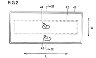
- FIG. 2 is a development view of the first air bag and the second air bag according to the first embodiment.
- FIG. 3 is a cross-sectional view showing a state where the first air bag and the second air bag shown in FIG. 2 are pressurized.
- FIG. 3 shows a cross-sectional view corresponding to the portion along the line III-III shown in FIG.
- the first air bag 41 and the second air bag 42 will be described with reference to FIGS. 2 and 3.
- the first air bag 41 has a belt-like and bag-like shape having a substantially rectangular shape in a plan view when deployed.
- the first air bladder 41 has a length direction L that is a circumferential direction in a state of being wound around the measurement target region, and a width direction W that is orthogonal to the length direction L.
- the first air bag 41 has a pair of outer surfaces 41a and 41b and a pair of inner surfaces 41c and 41d.
- a first nipple 43 is provided on one outer surface 41a of the pair of outer surfaces 41a and 41b.
- the first air bladder 41 expands and contracts when air enters and exits through the first nipple 43.
- the second air bag 42 has a belt-like and bag-like shape having a substantially rectangular shape in a plan view in the expanded state.
- the outer shape of the second air bag 42 is smaller than the outer shape of the first air bag 41.
- the second air bag 42 is accommodated in the first air bag 41.
- the second air bag 42 is located at the center in the longitudinal direction of the first air bag 41 in a state where both the first air bag 41 and the second air bag 42 are deployed in a planar shape.
- the second air bag 42 has a pair of outer surfaces 42a and 42b and a pair of inner surfaces 42c and 42d.
- the pair of outer surfaces 42 a and 42 b of the second air bag 42 oppose the pair of inner surfaces 41 c and 41 d of the first air bag 41, respectively.
- the second nipple 44 is provided on one outer surface 42a of the pair of outer surfaces 42a and 42b.
- the second air bag 42 expands and contracts when air enters and exits through the second nipple 44.
- the second nipple 44 is provided, for example, at a substantially central portion in the length direction L and the width direction W of the second air bag 42. By providing the second nipple 44 at such a position, the second air bag 42 can be inflated substantially uniformly.
- the first nipple 43 is disposed at a position corresponding to the outer edge portion of the second air bag 42 or at a position outside the outer edge portion in a state where the first air bag 41 and the second air bag 42 are both deployed in a plane. It is preferred that
- the position corresponding to the outer edge of the second air bag 42 or the position outside the outer edge is in the inserted state, the first air bag 41 is not inflated, and the second air bag 42 is not inflated.
- the first nipple 43 is a position where it is not blocked by the second air bag 42.
- the position corresponding to the outer edge portion of the second air bag 42 is the outer edge portion of the second air bag 42 when viewed in plan in a state where the first air bag 41 and the second air bag 42 are deployed.
- a position on the inner side from the outer edge of the second air bag 42 is also included.
- first nipple 43 is connected to the second nipple 44 along a direction parallel to the width direction of the first air bag 41 in a state where both the first air bag 41 and the second air bag 42 are deployed in a planar shape. It is preferable that they are arranged side by side.
- the first nipple 43 is located outside the outer edge portion of the second fluid bag in a state where both the first air bag 41 and the second air bag 42 are deployed in a plane.
- the second nipple 44 is arranged along a direction parallel to the width direction of the first air bag 41.
- the second nipple 44 penetrates the inner surface 41c of the first air bag 41 facing the outer surface 42a of the second air bag 42 and is drawn out to the outside.
- the first air bag 41 and the second air bag 42 are preferably formed of a bag-like member formed using a resin sheet.
- a resin sheet As the material of the resin sheet constituting the first air bag 41 and the second air bag 42, any material can be used as long as it is highly stretchable and does not leak air from the internal space. From this point of view, suitable materials for the resin sheet include ethylene-vinyl acetate copolymer, soft vinyl chloride, polyurethane, polyamide and the like.
- the internal spaces of both the first air bag 41 and the second air bag 42 are pressurized and inflated.
- the internal space of the first air bladder 41 may be pressurized first, or the internal space of the second air bladder 42 may be pressurized first.
- the position corresponding to the outer edge portion of the second air bag 42 or the outer edge portion Since the second air bag 42 is inflated by introducing air into the second air bag 42 prior to the first air bag 41, the first nipple 43 is disposed at the outer position. Therefore, the second air bag 42 can be prevented from being blocked. Thereby, air can be reliably introduced into the first nipple 43.
- the first air bag 41 is measured even when the amount of air supplied to the first air bag 41 is small using the Pascal principle.
- part can be amplified.
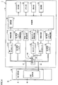
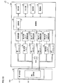
- FIG. 4 is a diagram showing a functional block configuration of the sphygmomanometer according to the first embodiment. With reference to FIG. 4, the functional block of the sphygmomanometer 1 will be described.
- the main body 10 includes a control unit 20, a memory unit 22, a power supply unit 24, and a first pressure P1 sensor 31A1 as a pressure detection device.
- a second pressure P2 sensor 31A2 a pressure pump 32, a flow path switching valve 33 as a switching valve, a first exhaust valve 34, a second exhaust valve 35, an oscillation circuit 51A1, and an oscillation circuit 51A2.
- a pressure pump drive circuit 52, a switching valve drive circuit 53, a first exhaust valve drive circuit 54, and a second exhaust valve drive circuit 55 are included.
- the pressurization pump 32, the first exhaust valve 34, the flow path switching valve 33, the first exhaust valve 34 and the second exhaust valve 35 are used to increase and decrease the space inside the first air bag 41 and the second air bag 42. It corresponds to a decompression mechanism.
- the pressurizing / depressurizing mechanism starts from the first state in which the internal space of one fluid bag of the first air bag 41 and the second air bag 42 is pressurized and inflated, while maintaining the sealed state of one fluid bag. It is comprised so that it can switch to the 2nd state which pressurizes and expands the internal space of the other fluid bag among the bag 41 and the 2nd air bag 42.
- the control unit 20 is configured by, for example, a CPU (Central Processing Unit), and is a means for controlling the entire sphygmomanometer 1.
- the control unit 20 includes a calculation unit 25 that calculates a blood pressure based on pressure information detected by the first pressure P1 sensor 31A1 in a state where the cuff 40 is worn as an area to be measured.
- the memory unit 22 is configured by, for example, a ROM (Read-Only Memory) or a RAM (Random-Access Memory), and stores a program for causing the control unit 20 or the like to execute a processing procedure for blood pressure measurement, This is a means for storing measurement results and the like.
- ROM Read-Only Memory
- RAM Random-Access Memory
- the display unit 21 is configured by, for example, an LCD (Liquid Crystal Display), and is a means for displaying measurement results and the like.
- the operation unit 23 is a means for accepting an operation by a user or the like and inputting a command from the outside to the control unit 20 or the power supply unit 24.
- the power supply unit 24 is means for supplying power to the control unit 20.
- the control unit 20 sends control signals for driving the pressure pump 32, the flow path switching valve 33, the first exhaust valve 34, and the second exhaust valve 35 to the pressure pump driving circuit 52, the switching valve driving circuit 53, the first The first exhaust valve drive circuit 54 and the second exhaust valve drive circuit 55 are input. Further, the control unit 20 inputs the blood pressure value calculated by the calculation unit 25 to the memory unit 22 and the display unit 21 as a measurement result.
- the sphygmomanometer 1 may further include an output unit that outputs a blood pressure value as a measurement result to an external device (for example, a PC (Personal Computer) or a printer).
- an external device for example, a PC (Personal Computer) or a printer.
- the output unit for example, a serial communication line or a writing device for various recording media can be used.
- the pressurizing pump 32 pressurizes the internal space of the first air bag 41 and the internal space of the second air bag 42 by supplying air to the space inside the first air bag 41 and the second air bag 42.
- the pressurization pump 32 supplies air to the first air bag 41 and the second air bag 42 via the air pipe 60.
- One end side of the air tube 60 is connected to the pressurizing pump 32.
- the other end side of the air tube 60 branches into a first air tube 61 connected to the first air bag 41 and a second air tube 62 connected to the second air bag 42.
- the first air pipe 61 is connected to the first air bag 41 by inserting the tip of the first air pipe 61 into the first nipple 43.
- the second air pipe 62 is connected to the second air bag 42 by inserting the tip of the second air pipe 62 into the second nipple 44.
- the pressurization pump drive circuit 52 controls the operation of the pressurization pump 32 based on the control signal input from the control unit 20.
- the flow path switching valve 33 is provided in the air pipe 60. Specifically, the flow path switching valve 33 is provided at a branch portion between the first air pipe 61 and the second air pipe 62.
- the flow path switching valve 33 includes a state in which air is supplied to the first air bladder 41 via the first air tube 61 (a state in which the internal space of the first air bladder 41 is pressurized) and a second air tube 62. Is switched to a state in which air is supplied to the second air bag 42 (a state in which the internal space of the second air bag 42 is pressurized).
- the switching valve drive circuit 53 controls the operation of the flow path switching valve 33 based on the control signal input from the control unit 20.
- the first exhaust valve 34 is connected to the first air pipe 61.
- the first exhaust valve 34 is closed to maintain the internal pressure of the first air bag 41 or open the space inside the first air bag 41 to the outside to reduce the internal pressure of the first air bag 41.
- the first exhaust valve drive circuit 54 controls the operation of the first exhaust valve 34 based on the control signal input from the control unit 20.
- the second exhaust valve 35 is connected to the second air pipe 62.
- the second exhaust valve 35 closes and opens to maintain the internal pressure of the second air bag 42 or open the space inside the second air bag 42 to the outside to reduce the internal pressure of the second air bag 42.
- the second exhaust valve drive circuit 55 controls the operation of the second exhaust valve 35 based on the control signal input from the control unit 20.
- the internal pressure of the first air bag 41 can be measured by the first pressure P1 sensor 31A1.
- the internal pressure of the second air bag can be measured by the second pressure P2 sensor 31A2.
- the first pressure P1 sensor 31A1 and the second pressure P2 sensor 31A2 are capacitive sensors.
- the capacitance of the first pressure P1 sensor 31A1 changes according to the internal pressure of the first air bag 41.
- the oscillation circuit 51A1 generates a signal having an oscillation frequency corresponding to the capacitance of the first pressure P1 sensor 31A1, and inputs the generated signal to the control unit 20.
- the capacitance of the second pressure P2 sensor 31A2 changes according to the internal pressure of the second air bag 42.
- the oscillation circuit 51A2 generates a signal having an oscillation frequency corresponding to the capacitance of the second pressure P2 sensor 31A2, and inputs the generated signal to the control unit 20.
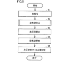
- FIG. 5 is a flowchart showing a measurement flow of the sphygmomanometer according to the first embodiment. The measurement flow of the sphygmomanometer 1 will be described with reference to FIG.
- the cuff 40 When measuring the blood pressure value, the cuff 40 is wrapped around the subject's upper arm in advance. In this state, when the operation unit 23 provided in the main body 10 is operated and the power supply of the sphygmomanometer 1 is turned on, power is supplied from the power supply unit 24 to the control unit 20 and the control unit 20 is driven. .
- the controller 20 first initializes the sphygmomanometer 1 after the driving (step S1).
- the control unit 20 controls the operation of the first exhaust valve 34 and the second exhaust valve 35 to open the space inside the first air bag 41 and the second air bag 42 to the outside. It is set to the opened state.
- control unit 20 waits for a measurement start instruction.
- the control unit 20 closes the first exhaust valve 34 and the second exhaust valve 35 and pressurizes the pressure pump. 32 is started (step S2).
- step S2 the control unit 20 controls the operation of the flow path switching valve 33 so that air is supplied to one of the first air bag 41 and the second air bag 42.
- the control unit 20 is configured so that air is supplied to the other of the first air bag 41 and the second air bag 42.
- the operation of the flow path switching valve 33 is controlled. Detailed operation in step S2 will be described later with reference to FIGS.
- the predetermined pressure is the first pressure P1 (see FIG. 7) when the internal space of the first air bladder 41 is first pressurized, and the internal space of the second air bladder 42 is pressurized first.
- the second pressure P2 see FIG. 9
- the first pressure P1 is smaller than the second pressure P2.
- the control unit 20 calculates the maximum blood pressure and the minimum blood pressure by a known procedure (step S3). Specifically, the control unit 20 changes the internal pressure of the first air bag 41 from the oscillation frequency obtained from the oscillation circuit 51A1 in the process of increasing the internal pressure of both the first air bag 41 and the second air bag 42. Obtained and extracted pulse wave information superimposed on the obtained internal pressure of the first air bladder 41. Then, the control unit 20 calculates the blood pressure value based on the extracted pulse wave information.
- step S3 the control unit 20 stops driving the pressurizing pump 32 and opens the first exhaust valve 34 and the second exhaust valve 35 to open the first air bag 41 and the first air bag 41. 2 The air in the air bag 42 is completely exhausted (step S4).
- the blood pressure value as the measurement result is displayed on the display unit 21 and the blood pressure value is stored in the memory unit 22 (step S5).
- control unit 20 waits for a power-off command, and when the operation unit 23 is operated and a power-off instruction is input, the supply of power from the power source unit 24 to the control unit 20 is cut off and a series of processing is performed. The procedure ends.
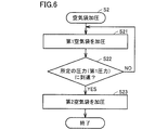
- FIG. 6 is a flowchart showing a first example of a process of pressurizing the air bag shown in FIG.
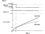
- FIG. 7 is a diagram showing the operating states of the flow path switching valve and the pressure pump in the first example shown in FIG. 6 and the changes in the internal pressures of the first air bag and the second air bag.
- a first example of the process of pressurizing the air bag will be described with reference to FIGS.
- step S21 the first air bag 41 is pressurized (step S21). Specifically, the operation of the flow path switching valve 33 is controlled, the second air pipe 62 side is closed, and the first air pipe 61 and the pressurizing pump 32 are communicated. Thereby, air can be supplied to the first air bag 41 via the first air pipe 61. In this state, the pressurizing pump 32 is driven, air is supplied to the first air bladder 41 via the first air pipe 61, and the internal space of the first air bladder 41 is pressurized.
- the control unit determines whether the internal pressure of the first air bladder 41 has reached a predetermined pressure (first pressure P1) based on the pressure information of the first air bladder 41 detected by the first pressure P1 sensor 31A1. It is determined whether or not (step S22). When it is determined that the internal pressure of the first air bladder 41 is smaller than the predetermined pressure (step S22: NO), the internal pressure of the first air bladder 41 is increased until the internal pressure of the first air bladder 41 reaches the first pressure P1. Continue to pressurize the internal space.
- the first pressure P1 is, for example, about 50 mmHg.
- step S22 When it is determined that the internal pressure of the first air bag 41 has reached the first pressure P1 (step S22: YES), the internal space of the second air bag 42 is pressurized (step S23).
- pressurization of the internal space of the first air bladder 41 is started from T0, and the internal pressure of the first air bladder 41 reaches the first pressure P1 at T1.
- the first air pipe 61 side is closed by the flow path switching valve 33, and the second air pipe 62 and the pressurizing pump 32 are communicated.
- air can be supplied to the second air bag 42 via the second air pipe 62.
- the closed state of the first exhaust valve 34 the closed state of the first air bag 41 is maintained.
- the internal space of the second air bag 42 is pressurized as shown in FIG.
- the air in the first air bag 41 is pressed by the second air bag 42, so that the internal pressure of the first air bag 41 increases even when air is not supplied to the first air bag 41. I will do it.
- the internal pressure of the 1st air bag 41 and the internal pressure of the 2nd air bag 42 rise.
- the first pressure P1 sensor 31A1 detects a change in the internal pressure of the first air bag 41, and based on the detected pressure information.
- the calculation unit 25 in the control unit 20 calculates the blood pressure of the user.
- the pressurizing / depressurizing mechanism pressurizes the internal space of the first air bag 41 and the internal pressure of the first air bag 41 reaches the first pressure P1, and then the first air bag 41.
- the internal space of the second air bag 42 is pressurized while maintaining the sealed state.
- the internal space of the first air bag 41 is pressurized by the fluid supplied through the first air pipe 61 by controlling the operations of the pressurization pump 32 and the flow path switching valve 33.
- the internal space of the second air bag 42 is pressurized by the fluid supplied through the second air pipe 62.
- the first air bag 41 is pressurized using the Pascal principle by pressurizing the internal space of the second air bag 42 while maintaining the sealed state of the first air bag 41 whose internal pressure has reached the first pressure P1. Even when the amount of air supplied to 41 is small, it is possible to amplify the force with which the first air bag 41 presses the measurement target region.
- the second air bag 42 is inflated after the first air bag 41 is inflated, blood pressure information measurement is performed as compared with the case where the second air bag 42 is inflated without inflating the first air bag 41.
- friction between the inner surface of the first air bag 41 and the inner surface of the second air bag 42 can be reduced.
- noise due to friction can be suppressed, and noise superimposed on the detection value of the pressure sensor can be suppressed. Thereby, measurement accuracy can be improved.
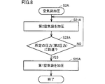
- FIG. 8 is a flowchart showing a second example of the process of pressurizing the air bag shown in FIG.
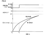
- FIG. 9 is a diagram showing the operating states of the flow path switching valve and the pressure pump in the second example shown in FIG. 8 and the changes in the internal pressures of the first air bag and the second air bag. With reference to FIG. 8 and FIG. 9, the 2nd example of the process of pressurizing an air bag is demonstrated.
- step S2A the second air bag 42 is pressurized (step S21A).
- the first air pipe 61 side is closed by the flow path switching valve 33 so that the second air pipe 62 and the pressurizing pump 32 communicate with each other.
- air can be supplied to the second air bag 42 via the second air pipe 62.
- the pressurizing pump 32 is driven, air is supplied to the second air bag 42 via the second air pipe 62, and the internal space of the second air bag 42 is pressurized.
- control unit determines whether the internal pressure of the second air bag 42 has reached a predetermined pressure (second pressure P2) based on the pressure information of the second air bag 42 detected by the first pressure P1 sensor 31A1. It is determined whether or not (step S22).
- the second pressure P2 is higher than the first pressure P1.
- step S22A NO
- the second air bag 42 is kept in the state until the internal pressure of the second air bag 42 reaches the second pressure P2. Continue to pressurize the internal space.
- step S22A When it is determined that the internal pressure of the second air bag 42 has reached the second pressure P2 (step S22A: YES), the first air bag 41 is pressurized (step S23A).
- pressurization of the internal space of the second air bag 42 is started from T0, and the internal pressure of the second air bag 42 reaches the second pressure P2 at T2.
- the second air pipe 62 side is closed by the flow path switching valve 33, and the first air pipe 61 and the pressurizing pump 32 are communicated. Thereby, air can be supplied to the first air bag 41 via the first air pipe 61. In this state, by maintaining the closed state of the second exhaust valve 35, the sealed state of the second air bag 42 is maintained.
- the internal space of the first air bladder 41 is pressurized as shown in FIG. At this time, while the air is supplied to the first air bladder 41, the air in the first air bladder 41 is pressed by the second air bladder 42 that has been previously inflated, so that only the first air bladder 41 is inflated.
- the internal pressure of the first air bag 41 increases with a small amount of air supply compared to the case.
- the internal pressure of the first air bladder 41 increases and the internal pressure of the second air bladder 42 increases.
- the first pressure P1 sensor 31A1 detects a change in the internal pressure of the first air bag 41, and the detected pressure information Based on this, the calculation unit 25 in the control unit 20 calculates the blood pressure of the user.
- the pressurizing / depressurizing mechanism pressurizes the internal space of the second air bladder 42 and the internal pressure of the second air bladder 42 reaches the second pressure P2, and then the second air bladder 42.
- the internal space of the first air bag 41 is pressurized while maintaining the sealed state.
- the internal space of the second air bag 42 is pressurized by the fluid supplied through the second air pipe 62 by controlling the operation of the pressurizing pump 32 and the flow path switching valve 33.
- the internal space of the first air bag 41 is pressurized by the fluid supplied through the first air pipe 61.
- the first air bag is pressurized using the Pascal principle by pressurizing the internal space of the first air bag 41 while maintaining the sealed state of the second air bag 42 whose internal pressure has reached the second pressure P2. Even when the amount of air supplied to 41 is small, it is possible to amplify the force with which the first air bag 41 presses the measurement target region.
- the first air bag 41 is inflated after the second air bag 42 is inflated, blood pressure information measurement is performed as compared with the case where the second air bag 42 is inflated without inflating the first air bag 41.
- friction between the inner surface of the first air bag 41 and the inner surface of the second air bag 42 can be reduced.
- noise due to friction can be suppressed, and noise superimposed on the detection value of the pressure sensor can be suppressed. Thereby, measurement accuracy can be improved.
- the case where the second pressure P2 sensor 31A2 for detecting the internal pressure of the second air bag 42 is provided is described as an example.
- the present invention is not limited to this, and the air bag described above is used.
- the internal pressure of the first air bag 41 is adjusted by the second pressure P2 sensor 31A2 even when the flow path switching valve 33 is switched to the second state. Can be measured.
- the first pressure P1 sensor 31A1 and the oscillation circuit 51A1 can be omitted.
- the second pressure P2 sensor 31A2 corresponds to a pressure detection device.
- FIG. 10 is a diagram illustrating a configuration of functional blocks of the sphygmomanometer according to the second embodiment.
- a blood pressure monitor 1A according to the second embodiment will be described with reference to FIG.
- the sphygmomanometer 1 ⁇ / b> A according to the second embodiment is not provided with the flow path switching valve 33 when compared with the sphygmomanometer 1 according to the first embodiment, and the first air bag 41.
- the second air bag 42 is different from the second air bag 42 in that it is pressurized using a flow path and a pump independent of each other.
- the sphygmomanometer 1A according to the second embodiment differs from the sphygmomanometer 1 according to the first embodiment in the configuration of the air tube 60A and the main body 10A.
- the configuration of the cuff 40 according to the second embodiment is substantially the same as that of the first embodiment.
- the air tube 60A includes a first air tube 61A and a second air tube 62A that are independent of each other.
- the distal end side of the first air pipe 61A is connected to the first nipple 43 of the first air bag 41, and the proximal end side of the first air pipe 61 is connected to a first pressurizing pump 32A1 described later.
- the distal end side of the second air tube 62 is connected to the second nipple 44 of the second air bladder 42, and the proximal end side of the second air tube 62 is connected to a second pressurizing pump 32A2 described later.
- the main body 10A pressurizes the first pressurizing pump 32A1 for pressurizing the internal space of the first air bladder 41 and the internal space of the second air bladder 42.
- the second pressurizing pump 32A2 is provided mainly independently.
- the first pressurizing pump 32A1 supplies air to the first air bag 41 via the first air pipe 61A.
- the second pressurizing pump 32A2 supplies air to the second air bag 42 via the second air pipe 62A.
- the main body 10A includes a first pump drive circuit 52A1 for driving the first pressurization pump 32A1, and a second pump drive circuit 52A2 for driving the second pressurization pump 32A2.
- the first pump drive circuit 52A1 and the second pump drive circuit 52A2 control the operations of the first pressurization pump 32A1 and the second pressurization pump 32A2 based on the input signal from the control unit 20, respectively.
- the main body 10A also includes a first pressure P1 sensor 31A1 for measuring the internal pressure of the first air bladder 41 and a second pressure P2 sensor 31A2 for measuring the internal pressure of the second air bladder 42.
- the first pressurization pump 32A1, the first exhaust valve 34, the second pressurization pump 32A2, and the second exhaust valve 35 are spaces inside the first air bag 41 and the second air bag 42.
- the pressurizing / depressurizing mechanism starts from the first state in which one of the first air bag 41 and the second air bag 42 is pressurized and inflated, and maintains the sealed state of the one air bag 41 and the first air bag 41 and
- the second air bag 42 is configured to be switchable to a second state in which the other fluid bag is pressurized and expanded.
- blood pressure information is measured based on the measurement method according to the first embodiment. Specifically, similar to the first embodiment, the same operations as in steps S1 to S5 are performed.
- step S2 as in the first embodiment, an operation based on the first example or the second example of the process of pressurizing the air bag is performed.
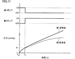
- FIG. 11 shows operating states of the first pressure pump and the second pressure pump in the first example of the step of pressurizing the air bag according to the second embodiment, and changes in internal pressures of the first air bag and the second air bag.
- the first pressurizing pump 32A1 is driven with the second pressurizing pump 32A2 stopped.
- air is supplied to the first air bag 41 via the first air tube 61A, and the first air bag 41 is pressurized.
- the control unit determines whether the internal pressure of the first air bladder 41 has reached a predetermined pressure (first pressure P1) based on the pressure information of the first air bladder 41 detected by the first pressure P1 sensor 31A1. Judge whether or not. When it is determined that the internal pressure of the first air bladder 41 is smaller than the predetermined pressure, the pressurization of the first air bladder 41 is continued until the internal pressure of the first air bladder 41 reaches the first pressure P1.
- first pressure P1 a predetermined pressure
- the second air bag 42 is pressurized.
- pressurization of the internal space of the first air bladder 41 is started from T0, and the pressure of the first air bladder 41 reaches the first pressure P1 at T3.
- the second pressurizing pump 32A2 is driven while the first pressurizing pump 32A1 is stopped. At this time, the closed state of the first air bag 41 can be maintained by closing the first exhaust valve 34.
- the internal space of the second air bag 42 is pressurized as shown in FIG. At this time, the air in the first air bag 41 is pressed by the second air bag 42, so that the internal pressure of the first air bag 41 increases even when air is not supplied to the first air bag 41. I will do it.
- the first pressure P1 sensor 31A1 detects a change in the internal pressure of the first air bag 41, and the detected pressure information Based on the above, the calculation unit 25 in the control unit 20 calculates the blood pressure of the user.
- the pressure increasing / decreasing mechanism pressurizes the internal space of the first air bladder 41 to After the internal pressure reaches the first pressure P1, the internal space of the second air bag 42 is pressurized while maintaining the sealed state of the first air bag 41.
- control unit 20 drives the first pressurization pump 32A1 while the second pressurization pump 32A2 is stopped, and then performs the second pressurization while the first pressurization pump 32A1 is stopped.
- the operation of the pressure increasing / decreasing mechanism is controlled so as to drive the pump 32A2.
- the amount of air supplied to the first air bag 41 can be reduced, thereby making it possible to capture a large pulse wave.
- measurement accuracy can be improved.
- the noise by the friction with the 1st air bag 41 and the 2nd air bag 42 can be suppressed, and the noise superimposed on the detected value of a pressure sensor can be suppressed. Thereby, measurement accuracy can be improved.
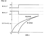
- FIG. 12 shows the operating state of the first pressure pump and the second pressure pump in the second example of the step of pressurizing the air bag according to the second embodiment, and the change in the internal pressure of the first air bag and the second air bag.
- the second pressurizing pump 32A2 is driven in a state where the first pressurizing pump 32A1 is stopped. .
- air is supplied to the second air bag 42 via the second air pipe 62 and the second air bag 42 is pressurized.
- control unit determines whether the internal pressure of the second air bag 42 has reached a predetermined pressure (second pressure P2) based on the pressure information of the second air bag 42 detected by the second pressure P2 sensor 31A2. Judge whether or not. When it is determined that the internal pressure of the second air bag 42 is smaller than the predetermined pressure, the pressurization of the second air bag 42 is continued until the internal pressure of the second air bag 42 reaches the second pressure P2.
- second pressure P2 a predetermined pressure
- the second air bag 42 When it is determined that the internal pressure of the second air bag 42 has reached the second pressure P2, the second air bag 42 is pressurized. In the present embodiment, pressurization of the second air bag 42 is started from T0, and the pressure of the second air bag 42 reaches the second pressure P2 at T4.
- the first pressurizing pump 32A1 is driven with the second pressurizing pump 32A2 stopped. At this time, by closing the second exhaust valve 35, the sealed state of the second air bag 42 can be maintained.
- the first air bladder 41 is pressurized as shown in FIG. At this time, while the air is supplied to the first air bladder 41, the air in the first air bladder 41 is pressed by the second air bladder 42 that has been previously inflated, so that only the first air bladder 41 is inflated.
- the internal pressure of the first air bag 41 increases with a small amount of air supply compared to the case.
- the internal pressure of the first air bladder 41 increases and the internal pressure of the second air bladder 42 increases.
- the first pressure P1 sensor 31A1 detects a change in the internal pressure of the first air bag 41, and the detected pressure information Based on this, the calculation unit 25 in the control unit 20 calculates the blood pressure of the user.
- the pressurizing / depressurizing mechanism pressurizes the internal space of the second air bag 42 so that the internal pressure of the second air bag 42 is the second pressure. After reaching P2, the internal space of the first air bladder 41 is pressurized while maintaining the sealed state of the second air bladder 42.
- the control unit 20 drives the second pressurization pump 32A2 with the first pressurization pump 31 stopped, the first pressurization with the second pressurization pump 32A2 stopped is performed.
- the operation of the pressure increasing / decreasing mechanism is controlled so as to drive the pump 32A1.
- the amount of air supplied to the first air bag 41 can be reduced, thereby making it possible to capture a large pulse wave.
- measurement accuracy can be improved.
- the noise by the friction with the 1st air bag 41 and the 2nd air bag 42 can be suppressed, and the noise superimposed on the detected value of a pressure sensor can be suppressed. Thereby, measurement accuracy can be improved.
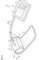
- FIG. 13 is a perspective view showing an external structure of a blood pressure monitor according to a modification. With reference to FIG. 13, the external structure of the blood pressure monitor according to the modification will be described.
- the blood pressure monitor 1B according to the modification is different from the blood pressure monitor 1 according to the first embodiment in the configuration of the air tube 60B.
- the first air pipe 61 and the second air pipe 62 included in the air pipe 60B are integrated on the main body 10 side. Specifically, on the main body 10 side, the body of the first air tube 61 and the body of the second air tube 62 are connected, and the first air tube 61 and the second air tube 62 are multi-cylinder type. It is configured.
- the first air pipe 61 and the second air pipe 62 are branched on the first nipple 43 and the second nipple 44 side.
- the air tube 60B may be configured.
- the blood pressure can be measured with a measurement flow almost the same as in the first embodiment.
- the pressurization measurement method is employed as the measurement method has been described as an example.
- the present invention is not limited to this, and the first air bag 41 and the second air bag are used.
- the case where an air bag through which air enters and exits is used as the fluid bag has been described as an example.
- the present invention is not limited to this, and gas other than air or uncompressed other than air
- a bag in which the viscous fluid enters and exits may be used. That is, in the embodiment described above, the case where the fluid whose flow rate is controlled is compressed air has been described as an example.
- the application target of the contents disclosed above is not limited to this, and the flow rate control is performed.
- the fluid to be applied may be a high-pressure gas other than compressed air, a liquid in a compressed environment, or the like.
Abstract
This blood pressure information measurement device is provided with: a cuff including a first fluid bag, and a second fluid bag accommodated inside the first fluid bag; a pressure increase/decrease mechanism which increases and decreases the pressure of the internal space of the first fluid bag and the pressure of the internal space of the second fluid bag; a control unit for controlling operation of the pressure increase/decrease mechanism; a pressure detection device for detecting the internal pressure of the first fluid bag; and a calculation unit for calculating blood pressure on the basis of pressure information detected by the pressure detection device. During the calculation of blood pressure information, the control unit controls the operation of the pressure increase/decrease mechanism to: pressurize and expand the internal space of one fluid bag among the first and second fluid bags such that the internal pressure of the one fluid bag reaches a prescribed pressure; and subsequently pressurize and expand the internal space of the other fluid bag among the first and second fluid bags, while maintaining the one fluid bag in a sealed state.
Description
本発明は、血圧情報の測定に利用される血圧情報測定装置に関し、より特定的には、流体袋を用いて生体を圧迫することで血圧情報が測定可能とされる血圧情報測定装置に関する。
The present invention relates to a blood pressure information measuring device used for measuring blood pressure information, and more specifically to a blood pressure information measuring device capable of measuring blood pressure information by pressing a living body using a fluid bag.
血圧情報を測定することは、被験者の健康状態を知る上で非常に重要なことである。近年においては、従来から健康管理の代表的な指標として広くその有用性が認められている収縮期血圧値(以下、最高血圧)、拡張期血圧値(以下、最低血圧)等を測定することに限られず、脈波を測定することによって心臓負荷や動脈硬化度等を捉える試みがなされている。
Measure blood pressure information is very important for knowing the health status of subjects. In recent years, the systolic blood pressure value (hereinafter referred to as “maximum blood pressure”), the diastolic blood pressure value (hereinafter referred to as “minimum blood pressure”), etc., which have been widely recognized as useful indicators for health care, have been widely used. However, the present invention is not limited, and attempts have been made to capture the cardiac load and the degree of arteriosclerosis by measuring the pulse wave.
血圧情報測定装置は、測定した血圧情報に基づいてこれら健康管理のための指標を得るための装置であり、循環器系疾患の早期発見や予防、治療等の分野においてさらなる活用が期待されている。なお、血圧情報には、最高血圧、最低血圧、平均血圧、脈波、脈拍、動脈硬化度を示す各種指標等、循環器系の種々の情報が広く含まれる。
The blood pressure information measuring device is a device for obtaining an index for health management based on the measured blood pressure information, and further utilization is expected in the fields of early detection, prevention, treatment, etc. of cardiovascular diseases. . The blood pressure information includes a wide variety of information on the circulatory system, such as various indices indicating maximum blood pressure, minimum blood pressure, average blood pressure, pulse wave, pulse, and degree of arteriosclerosis.
一般に、血圧情報の測定には、血圧情報測定装置用カフ(以下、単にカフとも称する)が利用される。ここで、カフとは、内空を有する流体袋を含む帯状または環状の構造物であって身体の一部に装着が可能なものを意味し、気体や液体等の流体を上記内空に注入することによって流体袋を膨張および収縮させて血圧情報の測定に利用されるもののことを指す。なお、カフは、腕帯あるいはマンシェットとも呼ばれる。
Generally, a blood pressure information measuring device cuff (hereinafter also simply referred to as a cuff) is used for measuring blood pressure information. Here, the cuff means a band-like or annular structure including a fluid bag having an inner space, which can be attached to a part of the body, and fluid such as gas or liquid is injected into the inner space. This means that the fluid bag is inflated and contracted to be used for measuring blood pressure information. The cuff is also called an armband or a manchette.
通常、カフは、その長さ方向に沿って測定対象部位(例えば、上腕)に巻装される。カフの幅方向への長さ(長さ方向に直交する方向の長さ、カフ幅という)が測定対象部位の太さに適合していないと、正確な血圧測定ができない場合がある。
Usually, the cuff is wound around the measurement target part (for example, the upper arm) along its length direction. If the length in the width direction of the cuff (the length in the direction orthogonal to the length direction, referred to as the cuff width) does not match the thickness of the region to be measured, accurate blood pressure measurement may not be possible.
測定対象部位の太さを判断して、血圧情報を測定する血圧情報測定装置が開示された文献として、たとえば、特開2012-147995号公報(特許文献1)が挙げられる。
For example, JP 2012-147995 A (Patent Document 1) discloses a blood pressure information measuring apparatus that measures the blood pressure information by determining the thickness of a measurement target region.
特許文献1に開示の血圧情報測定装置は、第1空気袋と、第1空気袋に内包された第2空気袋とを含む血圧情報測定装置用カフを備える。血圧情報測定装置によって血圧情報を測定する際には、使用者が予め測定対象部位が太いか細いかを入力し、当該入力情報に従って、第1空気袋および第2空気袋のいずれか一方を加圧する。太いと入力された場合には、第1空気袋を加圧し、細いと入力された場合には第2空気袋が加圧される。
The blood pressure information measuring device disclosed in Patent Document 1 includes a blood pressure information measuring device cuff including a first air bag and a second air bag contained in the first air bag. When blood pressure information is measured by the blood pressure information measuring device, the user inputs in advance whether the measurement target region is thick or thin, and pressurizes either the first air bag or the second air bag according to the input information. . When it is input that it is thick, the first air bag is pressurized, and when it is input that it is thin, the second air bag is pressurized.
第1空気袋および第2空気袋のいずれか一方を加圧する際に、所定の基準圧力(第1空気袋を加圧する場合にはP1、第2空気袋を加圧する場合にはP2)に達するまでの時間を計測し、予め決定された閾値(第1空気袋を加圧する場合にはTh1、第2空気袋を加圧する場合にはTh2)よりも低い場合には、判断部が、測定対象部位は細いと判断し、当該閾値以上である場合には、判断部が、測定対象部位は太いと判断する。
When pressurizing either the first air bag or the second air bag, a predetermined reference pressure (P1 when pressurizing the first air bag, P2 when pressurizing the second air bag) is reached. Until the threshold value is lower than a predetermined threshold (Th1 when pressurizing the first air bag, Th2 when pressurizing the second air bag), The part is determined to be thin, and if it is equal to or greater than the threshold, the determination unit determines that the measurement target part is thick.
判断部の判断と初期の入力情報が一致する場合には、入力情報に基づいて加圧した第1空気袋および第2空気袋の一方を継続して加圧して、血圧情報を測定する。判断部の判断と初期の入力情報が異なる場合には、入力情報に基づいて加圧した第1空気袋および第2空気袋の一方の加圧を停止し、第1空気袋および第2空気袋の他方を加圧して、血圧情報を測定する。
When the judgment of the judgment unit and the initial input information match, one of the first air bag and the second air bag pressurized based on the input information is continuously pressurized and blood pressure information is measured. If the determination by the determination unit and the initial input information are different, pressurization of one of the first air bag and the second air bag pressurized based on the input information is stopped, and the first air bag and the second air bag are stopped. The other blood pressure is pressurized and blood pressure information is measured.
特許文献1に開示の血圧情報測定装置用カフにあっては、上述のように、使用者が予め測定対象部位は「太い」と入力し、判断部が測定対象部位は「太い」と判断した場合には、第1空気袋のみを加圧させて、血圧情報を測定することとなる。このため、第1空気袋には相当量の空気が供給されてしまい、使用者の脈波を大きくとらえることができず、測定精度が低下してしまう。
In the cuff for a blood pressure information measuring device disclosed in Patent Document 1, as described above, the user inputs “thick” as the measurement target part in advance, and the determination unit determines that the measurement target part is “thick”. In this case, only the first air bag is pressurized and blood pressure information is measured. For this reason, a considerable amount of air is supplied to the first air bag, and the pulse wave of the user cannot be captured greatly, resulting in a decrease in measurement accuracy.
一方、使用者が予め測定対象部位は「細い」と入力し、判断部が測定対象部位は「細い」と判断した場合には、第2空気袋のみを加圧させて、血圧情報を測定することとなる。第2空気袋は、第1空気袋内に収容されているため、第1空気袋を膨張させることなく第2空気袋を膨張させる場合には、第2空気袋の外表面と第1空気袋の内表面とが擦れてしまい、この結果、第2空気袋がスムーズに膨張することができなくなる。このような第1空気袋と第2空気袋との摩擦は、圧力センサの検出値にノイズとなって重畳されてしまう。これにより、測定精度が低下してしまう。
On the other hand, when the user inputs in advance “thin” as the measurement target region and the determination unit determines that the measurement target region is “thin”, only the second air bag is pressurized and blood pressure information is measured. It will be. Since the second air bag is accommodated in the first air bag, when the second air bag is inflated without inflating the first air bag, the outer surface of the second air bag and the first air bag As a result, the second air bag cannot be inflated smoothly. Such friction between the first air bag and the second air bag is superimposed on the detection value of the pressure sensor as noise. Thereby, measurement accuracy will fall.
本発明は、上記のような問題に鑑みてなされたものであり、本発明の目的は、第1流体袋と、当該第1流体袋に収容される第2流体袋とを備えた構成において、測定精度を向上させることができる血圧情報測定装置を提供することにある。
This invention is made | formed in view of the above problems, The objective of this invention is the structure provided with the 1st fluid bag and the 2nd fluid bag accommodated in the said 1st fluid bag, An object of the present invention is to provide a blood pressure information measuring device capable of improving measurement accuracy.
本発明に基づく血圧情報測定装置は、流体が出入りすることにより膨縮する第1流体袋、および上記第1流体袋の内部に収容され、流体が出入りすることにより膨縮する第2流体袋を含むカフと、上記第1流体袋の内部空間および上記第2流体袋の内部空間を加減圧する加減圧機構と、上記加減圧機構の動作を制御する制御部と、上記第1流体袋の内圧を検知する圧力検知装置と、上記カフが測定対象部位に装着された状態において、上記圧力検知装置にて検知された圧力情報に基づいて血圧を算出する演算部と、を備える。上記圧力検知装置および上記演算部を用いて血圧情報を算出する際に、上記制御部は、上記加減圧機構の動作を制御することにより、上記第1流体袋および上記第2流体袋のうち一方の流体袋の上記内部空間を加圧して膨張させることで上記一方の流体袋の内圧が所定の圧力に到達した後に、上記一方の流体袋の密閉状態を維持しつつ上記第1流体袋および上記第2流体袋のうち他方の流体袋の上記内部空間を加圧して膨張させる。
The blood pressure information measurement device according to the present invention includes a first fluid bag that expands and contracts when fluid enters and exits, and a second fluid bag that is accommodated inside the first fluid bag and expands and contracts when fluid enters and exits. A cuff, a pressure increasing / decreasing mechanism for increasing / decreasing the internal space of the first fluid bag and the second fluid bag, a control unit for controlling the operation of the pressure increasing / decreasing mechanism, and an internal pressure of the first fluid bag. And a calculation unit that calculates blood pressure based on pressure information detected by the pressure detection device in a state where the cuff is attached to the measurement target part. When calculating blood pressure information using the pressure detection device and the calculation unit, the control unit controls one of the first fluid bag and the second fluid bag by controlling the operation of the pressure increasing / decreasing mechanism. After the internal pressure of the one fluid bag reaches a predetermined pressure by pressurizing and inflating the internal space of the fluid bag, the first fluid bag and the above-described fluid bag while maintaining the sealed state of the one fluid bag The internal space of the other fluid bag of the second fluid bag is pressurized and inflated.
上記本発明に基づく血圧情報測定装置にあっては、上記加減圧機構は、上記第2流体袋の上記内部空間を加圧して上記第2流体袋の内圧が第1圧力に到達した後に、上記第2流体袋の密閉状態を維持しつつ上記第1流体袋の上記内部空間を加圧してもよい。
In the blood pressure information measuring device according to the present invention, the pressurizing / depressurizing mechanism pressurizes the internal space of the second fluid bag and the internal pressure of the second fluid bag reaches the first pressure, and then The internal space of the first fluid bag may be pressurized while maintaining the sealed state of the second fluid bag.
上記本発明に基づく血圧情報測定装置にあっては、上記加減圧機構は、第1加圧ポンプと第2加圧ポンプとを含んでいてもよい。この場合には、上記第1加圧ポンプは、上記第1流体袋の上記内部空間を加圧し、上記第2加圧ポンプは、上記第2流体袋の上記内部空間を加圧することが好ましい。さらにこの場合には、上記制御部は、上記第1加圧ポンプを停止させた状態で上記第2加圧ポンプを駆動させた後に、上記第2加圧ポンプを停止させた状態で上記第1加圧ポンプを駆動させるように、上記加減圧機構の動作を制御してもよい。
In the blood pressure information measuring device according to the present invention, the pressure increasing / decreasing mechanism may include a first pressurizing pump and a second pressurizing pump. In this case, it is preferable that the first pressurizing pump pressurizes the internal space of the first fluid bag, and the second pressurizing pump pressurizes the internal space of the second fluid bag. Further, in this case, the control unit drives the second pressure pump with the first pressure pump stopped, and then stops the first pressure pump with the second pressure pump stopped. You may control operation | movement of the said pressure increase / decrease mechanism so that a pressurization pump may be driven.
上記本発明に基づく血圧情報測定装置にあっては、上記加減圧機構は、単一の加圧ポンプと、流体供給経路と、切替弁とを含んでいてもよい。この場合には、上記加圧ポンプは、上記第1流体袋の上記内部空間および上記第2流体袋の上記内部空間を加圧することが好ましく、上記流体供給経路の一端側は、上記加圧ポンプに接続され、上記流体供給経路の他端側は、上記第1流体袋に接続される第1供給路および上記第2流体袋に接続される第2供給路に分岐することが好ましい。また、上記切替弁は、上記流体供給路に設けられ、上記第1供給路を介して上記第1流体袋に流体が供給される状態と、上記第2供給路を介して上記第2流体袋に流体が供給される状態とを切り替えることが好ましい。この場合には、上記制御部は、上記加圧ポンプおよび上記切替弁の動作を制御することにより、上記第2供給路を介して供給される流体によって上記第2流体袋の上記内部空間を加圧した後に、上記第1供給路を介して供給される流体によって上記第1流体袋の上記内部空間を加圧してもよい。
In the blood pressure information measuring device according to the present invention, the pressure increasing / decreasing mechanism may include a single pressurizing pump, a fluid supply path, and a switching valve. In this case, it is preferable that the pressurizing pump pressurizes the internal space of the first fluid bag and the internal space of the second fluid bag, and one end side of the fluid supply path is connected to the pressurizing pump. The other end of the fluid supply path is preferably branched into a first supply path connected to the first fluid bag and a second supply path connected to the second fluid bag. In addition, the switching valve is provided in the fluid supply path, the fluid is supplied to the first fluid bag via the first supply path, and the second fluid bag via the second supply path. It is preferable to switch the state in which the fluid is supplied to. In this case, the control unit controls the operations of the pressurizing pump and the switching valve to add the internal space of the second fluid bag with the fluid supplied through the second supply path. After pressurizing, the internal space of the first fluid bag may be pressurized by the fluid supplied through the first supply path.
上記本発明に基づく血圧情報測定装置にあっては、上記加減圧機構は、上記第1流体袋の上記内部空間を加圧して上記第1流体袋の内圧が第2圧力に到達した後に、上記第1流体袋の密閉状態を維持しつつ上記第2流体袋の上記内部空間を加圧してもよい。
In the blood pressure information measurement device according to the present invention, the pressurizing / depressurizing mechanism pressurizes the internal space of the first fluid bag and the internal pressure of the first fluid bag reaches the second pressure, and then The internal space of the second fluid bag may be pressurized while maintaining the sealed state of the first fluid bag.
上記本発明に基づく血圧情報測定装置にあっては、上記加減圧機構は、第1加圧ポンプと第2加圧ポンプとを含んでいてもよい。この場合には、上記第1加圧ポンプは、上記第1流体袋の上記内部空間を加圧し、上記第2加圧ポンプは、上記第2流体袋の上記内部空間を加圧することが好ましい。さらにこの場合には、上記制御部は、上記第2加圧ポンプを停止させた状態で上記第1加圧ポンプを駆動させた後に、上記第1加圧ポンプを停止させた状態で上記第2加圧ポンプを駆動させるように、上記加減圧機構の動作を制御してもよい。
In the blood pressure information measuring device according to the present invention, the pressure increasing / decreasing mechanism may include a first pressurizing pump and a second pressurizing pump. In this case, it is preferable that the first pressurizing pump pressurizes the internal space of the first fluid bag, and the second pressurizing pump pressurizes the internal space of the second fluid bag. Further, in this case, the control unit drives the first pressure pump with the second pressure pump stopped, and then stops the second pressure pump with the second pressure pump stopped. You may control operation | movement of the said pressure increase / decrease mechanism so that a pressurization pump may be driven.
上記本発明に基づく血圧情報測定装置にあっては、上記加減圧機構は、単一の加圧ポンプと、流体供給経路と、切替弁とを含んでいてもよい。この場合には、上記加圧ポンプは、上記第1流体袋の上記内部空間および上記第2流体袋の上記内部空間を加圧することが好ましく、上記流体供給経路の一端側は、上記加圧ポンプに接続され、上記流体供給経路の他端側は、上記第1流体袋に接続される第1供給路および上記第2流体袋に接続される第2供給路に分岐することが好ましい。また、上記切替弁は、上記流体供給路に設けられ、上記第1供給路を介して上記第1流体袋に流体が供給される状態と、上記第2供給路を介して上記第2流体袋に流体が供給される状態とを切り替えることが好ましい。この場合には、上記制御部は、上記加圧ポンプおよび上記切替弁の動作を制御することにより、上記第1供給路を介して供給される流体によって上記第1流体袋の上記内部空間を加圧した後に、上記第2供給路を介して供給される流体によって上記第2流体袋の上記内部空間を加圧してもよい。
In the blood pressure information measuring device according to the present invention, the pressure increasing / decreasing mechanism may include a single pressurizing pump, a fluid supply path, and a switching valve. In this case, it is preferable that the pressurizing pump pressurizes the internal space of the first fluid bag and the internal space of the second fluid bag, and one end side of the fluid supply path is connected to the pressurizing pump. The other end of the fluid supply path is preferably branched into a first supply path connected to the first fluid bag and a second supply path connected to the second fluid bag. In addition, the switching valve is provided in the fluid supply path, the fluid is supplied to the first fluid bag via the first supply path, and the second fluid bag via the second supply path. It is preferable to switch the state in which the fluid is supplied to. In this case, the control unit controls the operation of the pressurizing pump and the switching valve, thereby adding the internal space of the first fluid bag with the fluid supplied through the first supply path. After pressurizing, the internal space of the second fluid bag may be pressurized by the fluid supplied through the second supply path.
本発明によれば、第1流体袋と、当該第1流体袋に収容される第2流体袋とを備えた構成において、測定精度を向上させることができる血圧情報測定装置を提供することができる。
ADVANTAGE OF THE INVENTION According to this invention, in the structure provided with the 1st fluid bag and the 2nd fluid bag accommodated in the said 1st fluid bag, the blood pressure information measuring device which can improve a measurement precision can be provided. .
以下、本発明の実施の形態について、図を参照して詳細に説明する。以下に示す実施の形態においては、血圧情報測定装置用カフとして、最高血圧および最低血圧等の血圧値を測定することが可能に構成された上腕式の血圧計に使用される血圧計用カフを例示して説明を行なう。なお、以下においては、同一のまたは共通する部分について図中同一の符号を付し、その説明は繰り返さない。
Hereinafter, embodiments of the present invention will be described in detail with reference to the drawings. In the embodiment described below, a sphygmomanometer cuff used for an upper-arm sphygmomanometer configured to be able to measure blood pressure values such as the highest blood pressure and the lowest blood pressure is used as the blood pressure information measurement device cuff. An explanation will be given by way of example. In the following, the same or common parts are denoted by the same reference numerals in the drawings, and description thereof will not be repeated.
(実施の形態1)
図1は、実施の形態1に係る血圧計の外観構造を示す斜視図である。図1を参照して、実施の形態1に係る血圧計1の概略的な構成について説明する。 (Embodiment 1)
1 is a perspective view showing an external structure of a sphygmomanometer according toEmbodiment 1. FIG. A schematic configuration of a sphygmomanometer 1 according to Embodiment 1 will be described with reference to FIG.
図1は、実施の形態1に係る血圧計の外観構造を示す斜視図である。図1を参照して、実施の形態1に係る血圧計1の概略的な構成について説明する。 (Embodiment 1)
1 is a perspective view showing an external structure of a sphygmomanometer according to
図1に示すように、血圧計1は、本体10と、カフ40と、流体供給路としてのエア管60とを備えている。エア管60は、分離されて構成された本体10とカフ40とを接続している。
As shown in FIG. 1, the sphygmomanometer 1 includes a main body 10, a cuff 40, and an air tube 60 as a fluid supply path. The air pipe 60 connects the main body 10 and the cuff 40 which are separated from each other.
エア管60は、第1供給路としての第1エア管61と第2供給路としての第2エア管62とを含む。第1エア管61と第2エア管62とは、たとえば互いに分離されている。第1エア管61および第2エア管62の各々は、たとえば可撓性を有する樹脂製のチューブによって構成されている。
The air pipe 60 includes a first air pipe 61 as a first supply path and a second air pipe 62 as a second supply path. The first air pipe 61 and the second air pipe 62 are separated from each other, for example. Each of the 1st air pipe 61 and the 2nd air pipe 62 is comprised by the resin-made tubes which have flexibility, for example.
本体10は、箱状のケーシングを有しており、その上面に表示部21および操作部23を有している。本体10は、測定時においてテーブル等の載置面に載置されて使用されるものである。
The main body 10 has a box-shaped casing, and has a display unit 21 and an operation unit 23 on an upper surface thereof. The main body 10 is used by being mounted on a mounting surface such as a table during measurement.
カフ40は、被装着部位としての上腕に巻き付けが可能な帯状の形状を有している。カフ40は、測定時において上腕に装着されて使用されるものであり、上腕に巻き付けられた装着状態において環状の形態をとる。カフ40は、外装カバー45と、第1流体袋としての第1空気袋41と、第2流体袋としての第2空気袋42とを含む。第1空気袋41および第2空気袋42の詳細については、図2および図3を用いて後述する。
The cuff 40 has a belt-like shape that can be wound around the upper arm as a wearing part. The cuff 40 is used by being attached to the upper arm at the time of measurement, and takes an annular form in the attached state wound around the upper arm. The cuff 40 includes an exterior cover 45, a first air bag 41 as a first fluid bag, and a second air bag 42 as a second fluid bag. Details of the first air bag 41 and the second air bag 42 will be described later with reference to FIGS. 2 and 3.
外装カバー45は、展開された状態において平面視略矩形状の帯状かつ袋状の形状を有する。外装カバー45は、装着状態において径方向外側に位置することとなる外側カバー部材45bと、装着状態において径方向内側に位置して上腕の表面に接触することとなる内側カバー部材45aとを含んでいる。
The outer cover 45 has a belt-like and bag-like shape that is substantially rectangular in a plan view in the unfolded state. The exterior cover 45 includes an outer cover member 45b that is positioned radially outside in the mounted state, and an inner cover member 45a that is positioned radially inside in contact with the upper arm surface. Yes.
外装カバー45は、外側カバー部材45bと内側カバー部材45aとが重ね合わされてそれらの周縁がバイアステープ(不図示)によって覆われた状態で接合(たとえば縫合や溶着等)されることで袋状に形成されている。
The exterior cover 45 is formed into a bag shape by joining the outer cover member 45b and the inner cover member 45a so that their peripheral edges are covered with a bias tape (not shown) (for example, stitching or welding). Is formed.
外装カバー45の長手方向の一端部よりの外周面には、面ファスナ46が設けられており、当該一端部とは反対側に位置する外装カバー45の他端部寄りの内周面には、面ファスナ47が設けられている。面ファスナ46は、たとえばフックファスナによって構成されており、面ファスナ47は、たとえばループファスナによって構成されている。
A surface fastener 46 is provided on the outer peripheral surface from one end in the longitudinal direction of the outer cover 45, and on the inner peripheral surface near the other end of the outer cover 45 located on the opposite side to the one end, A surface fastener 47 is provided. The hook-and-loop fastener 46 is constituted by, for example, a hook fastener, and the hook-and-loop fastener 47 is constituted by, for example, a loop fastener.
これら面ファスナ46,47は、外装カバー45が上腕に巻き付けられて当該外装カバー45の上記一端部寄りの部分と上記他端部寄りの部分とが上腕の表面上において重ね合わされることにより係止可能なものである。このため、カフ40を上腕に巻き付けた状態において当該面ファスナ46,47を係止させることにより、装着状態において外装カバー45が上腕に対して固定されることになる。
These hook-and- loop fasteners 46 and 47 are locked when the outer cover 45 is wound around the upper arm and the portion near the one end and the portion near the other end of the outer cover 45 are overlapped on the surface of the upper arm. It is possible. For this reason, the outer cover 45 is fixed to the upper arm in the mounted state by locking the surface fasteners 46 and 47 in a state where the cuff 40 is wound around the upper arm.
図2は、実施の形態1に係る第1空気袋および第2空気袋の展開図である。図3は、図2に示す第1空気袋および第2空気袋を加圧した状態を示す断面図である。なお、図3は、図2に示すIII-III線に沿った部分に対応する断面図を示している。図2および図3を参照して、第1空気袋41および第2空気袋42について説明する。
FIG. 2 is a development view of the first air bag and the second air bag according to the first embodiment. FIG. 3 is a cross-sectional view showing a state where the first air bag and the second air bag shown in FIG. 2 are pressurized. FIG. 3 shows a cross-sectional view corresponding to the portion along the line III-III shown in FIG. The first air bag 41 and the second air bag 42 will be described with reference to FIGS. 2 and 3.
図2に示すように、第1空気袋41は、展開した状態において、平面視略矩形形状の帯状かつ袋状の形状を有する。第1空気袋41は、測定対象部位に巻き付けられた状態において周方向となる長さ方向Lおよび長さ方向Lに直交する幅方向Wを有する。
As shown in FIG. 2, the first air bag 41 has a belt-like and bag-like shape having a substantially rectangular shape in a plan view when deployed. The first air bladder 41 has a length direction L that is a circumferential direction in a state of being wound around the measurement target region, and a width direction W that is orthogonal to the length direction L.
第1空気袋41は、一対の外表面41a,41bおよび一対の内表面41c,41dを有する。
The first air bag 41 has a pair of outer surfaces 41a and 41b and a pair of inner surfaces 41c and 41d.
上記一対の外表面41a,41bのうち一方の外表面41aには、第1ニップル43が設けられている。第1空気袋41は、第1ニップル43を介して空気が出入りすることにより膨縮する。
A first nipple 43 is provided on one outer surface 41a of the pair of outer surfaces 41a and 41b. The first air bladder 41 expands and contracts when air enters and exits through the first nipple 43.
第2空気袋42は、展開した状態において、平面視略矩形形状の帯状かつ袋状の形状を有する。第2空気袋42の外形は、第1空気袋41の外形よりも小さくなっている。第2空気袋42は、第1空気袋41に収容されている。第2空気袋42は、第1空気袋41および第2空気袋42を共に平面状に展開させた状態において、第1空気袋41の長方向における中央に位置している。
The second air bag 42 has a belt-like and bag-like shape having a substantially rectangular shape in a plan view in the expanded state. The outer shape of the second air bag 42 is smaller than the outer shape of the first air bag 41. The second air bag 42 is accommodated in the first air bag 41. The second air bag 42 is located at the center in the longitudinal direction of the first air bag 41 in a state where both the first air bag 41 and the second air bag 42 are deployed in a planar shape.
第2空気袋42は、一対の外表面42a,42bおよび一対の内表面42c,42dを有する。第2空気袋42の一対の外表面42a,42bは、それぞれ第1空気袋41の一対の内表面41c,41dに対向する。
The second air bag 42 has a pair of outer surfaces 42a and 42b and a pair of inner surfaces 42c and 42d. The pair of outer surfaces 42 a and 42 b of the second air bag 42 oppose the pair of inner surfaces 41 c and 41 d of the first air bag 41, respectively.
上記一対の外表面42a,42bのうち一方の外表面42aには、第2ニップル44が設けられている。第2空気袋42は、第2ニップル44を介して空気が出入りすることにより膨縮する。
The second nipple 44 is provided on one outer surface 42a of the pair of outer surfaces 42a and 42b. The second air bag 42 expands and contracts when air enters and exits through the second nipple 44.
第2ニップル44は、たとえば、第2空気袋42の長さ方向Lおよび幅方向Wの略中央部に設けられている。このような位置に第2ニップル44を設けることにより、第2空気袋42を略均一に膨張させることができる。
The second nipple 44 is provided, for example, at a substantially central portion in the length direction L and the width direction W of the second air bag 42. By providing the second nipple 44 at such a position, the second air bag 42 can be inflated substantially uniformly.
第1ニップル43は、第1空気袋41および第2空気袋42を共に平面状に展開させた状態において、第2空気袋42の外縁部に対応した位置または当該外縁部よりも外側位置に配置されることが好ましい。
The first nipple 43 is disposed at a position corresponding to the outer edge portion of the second air bag 42 or at a position outside the outer edge portion in a state where the first air bag 41 and the second air bag 42 are both deployed in a plane. It is preferred that
ここで、上記第2空気袋42の外縁部に対応した位置または当該外縁部よりも外側位置は、挿着状態であって第1空気袋41が膨張しておらずかつ第2空気袋42が膨張した状態において、第1ニップル43が、第2空気袋42によって閉塞されることがない位置である。このため、上記第2空気袋42の外縁部に対応した位置とは、第1空気袋41および第2空気袋42を展開した状態において、平面視した場合に、第2空気袋42の外縁部に重なる位置だけでなく、第2空気袋42の外縁部から一定程度の内側の位置も含む。
Here, the position corresponding to the outer edge of the second air bag 42 or the position outside the outer edge is in the inserted state, the first air bag 41 is not inflated, and the second air bag 42 is not inflated. In the inflated state, the first nipple 43 is a position where it is not blocked by the second air bag 42. For this reason, the position corresponding to the outer edge portion of the second air bag 42 is the outer edge portion of the second air bag 42 when viewed in plan in a state where the first air bag 41 and the second air bag 42 are deployed. In addition to a position overlapping with the second air bag 42, a position on the inner side from the outer edge of the second air bag 42 is also included.
また、第1ニップル43は、第1空気袋41および第2空気袋42を共に平面状に展開させた状態において、第1空気袋41の幅方向に平行な方向に沿って第2ニップル44と並ぶように配置されていることが好ましい。
In addition, the first nipple 43 is connected to the second nipple 44 along a direction parallel to the width direction of the first air bag 41 in a state where both the first air bag 41 and the second air bag 42 are deployed in a planar shape. It is preferable that they are arranged side by side.
実施の形態1においては、第1ニップル43は、第1空気袋41および第2空気袋42を共に平面状に展開させた状態において、上記第2流体袋の外縁部よりも外側の位置であって、第1空気袋41の幅方向に平行な方向に沿って第2ニップル44と並ぶように配置されている。
In the first embodiment, the first nipple 43 is located outside the outer edge portion of the second fluid bag in a state where both the first air bag 41 and the second air bag 42 are deployed in a plane. The second nipple 44 is arranged along a direction parallel to the width direction of the first air bag 41.
第2ニップル44は、第2空気袋42の外表面42aに対向する第1空気袋41の内表面41cを貫通して外部に引き出されている。
The second nipple 44 penetrates the inner surface 41c of the first air bag 41 facing the outer surface 42a of the second air bag 42 and is drawn out to the outside.
第1空気袋41および第2空気袋42は、好適には樹脂シートを用いて形成された袋状の部材にて構成されている。第1空気袋41および第2空気袋42を構成する樹脂シートの材質としては、伸縮性に富んでおり内部の空間からの漏気がないものであればどのようなものでも利用可能である。このような観点から、樹脂シートの好適な材質としては、エチレン-酢酸ビニル共重合体、軟質塩化ビニル、ポリウレタン、ポリアミド等が挙げられる。
The first air bag 41 and the second air bag 42 are preferably formed of a bag-like member formed using a resin sheet. As the material of the resin sheet constituting the first air bag 41 and the second air bag 42, any material can be used as long as it is highly stretchable and does not leak air from the internal space. From this point of view, suitable materials for the resin sheet include ethylene-vinyl acetate copolymer, soft vinyl chloride, polyurethane, polyamide and the like.
図3に示すように、血圧の測定時においては、第1空気袋41および第2空気袋42の双方の内部空間を加圧して膨張させる。後述するように、第1空気袋41の内部空間を先に加圧してもよいし、第2空気袋42の内部空間を先に加圧してもよい。
As shown in FIG. 3, when measuring blood pressure, the internal spaces of both the first air bag 41 and the second air bag 42 are pressurized and inflated. As will be described later, the internal space of the first air bladder 41 may be pressurized first, or the internal space of the second air bladder 42 may be pressurized first.
上述のように、第1ニップル43が、第1空気袋41および第2空気袋42を共に平面状に展開させた状態において、第2空気袋42の外縁部に対応した位置または当該外縁部よりも外側位置に配置されることにより、第1空気袋41よりも先に第2空気袋42に空気を導入して第2空気袋42を膨張させた場合であっても、第1ニップル43が、第2空気袋42によって閉塞されることを防止することができる。これにより、第1ニップル43の内部に空気を確実に導入することができる。
As described above, in a state where the first nipple 43 and the first air bag 41 and the second air bag 42 are both deployed in a plane, the position corresponding to the outer edge portion of the second air bag 42 or the outer edge portion. Since the second air bag 42 is inflated by introducing air into the second air bag 42 prior to the first air bag 41, the first nipple 43 is disposed at the outer position. Therefore, the second air bag 42 can be prevented from being blocked. Thereby, air can be reliably introduced into the first nipple 43.
また、第2空気袋42の内部空間を加圧されることにより、パスカルの原理を利用して、第1空気袋41への空気の供給量が少ない場合でも、第1空気袋41が測定対象部位を押圧する力を増幅させることができる。
Further, by pressurizing the internal space of the second air bag 42, the first air bag 41 is measured even when the amount of air supplied to the first air bag 41 is small using the Pascal principle. The force which presses a site | part can be amplified.
図4は、実施の形態1に係る血圧計の機能ブロックの構成を示す図である。図4を参照して、血圧計1の機能ブロックについて説明する。
FIG. 4 is a diagram showing a functional block configuration of the sphygmomanometer according to the first embodiment. With reference to FIG. 4, the functional block of the sphygmomanometer 1 will be described.
図4に示すように、本体10は、上述した表示部21および操作部23に加え、制御部20と、メモリ部22と、電源部24と、圧力検知装置としての第1圧力P1センサ31A1と、第2圧力P2センサ31A2と、加圧ポンプ32と、切替弁としての流路切替バルブ33と、第1排気バルブ34と、第2排気バルブ35と、発振回路51A1と、発振回路51A2と、加圧ポンプ駆動回路52と、切替バルブ駆動回路53と、第1排気バルブ駆動回路54と、第2排気バルブ駆動回路55とを含む。
As shown in FIG. 4, in addition to the display unit 21 and the operation unit 23 described above, the main body 10 includes a control unit 20, a memory unit 22, a power supply unit 24, and a first pressure P1 sensor 31A1 as a pressure detection device. A second pressure P2 sensor 31A2, a pressure pump 32, a flow path switching valve 33 as a switching valve, a first exhaust valve 34, a second exhaust valve 35, an oscillation circuit 51A1, and an oscillation circuit 51A2. A pressure pump drive circuit 52, a switching valve drive circuit 53, a first exhaust valve drive circuit 54, and a second exhaust valve drive circuit 55 are included.
加圧ポンプ32、第1排気バルブ34、流路切替バルブ33、第1排気バルブ34および第2排気バルブ35は、第1空気袋41および第2空気袋42の内部の空間を加減圧する加減圧機構に相当する。
The pressurization pump 32, the first exhaust valve 34, the flow path switching valve 33, the first exhaust valve 34 and the second exhaust valve 35 are used to increase and decrease the space inside the first air bag 41 and the second air bag 42. It corresponds to a decompression mechanism.
加減圧機構は、第1空気袋41および第2空気袋42のうち一方の流体袋の内部空間を加圧して膨張させる第1状態から、一方の流体袋の密閉状態を維持しつつ第1空気袋41および第2空気袋42のうち他方の流体袋の内部空間を加圧して膨張させる第2状態に切り替え可能に構成されている。
The pressurizing / depressurizing mechanism starts from the first state in which the internal space of one fluid bag of the first air bag 41 and the second air bag 42 is pressurized and inflated, while maintaining the sealed state of one fluid bag. It is comprised so that it can switch to the 2nd state which pressurizes and expands the internal space of the other fluid bag among the bag 41 and the 2nd air bag 42. FIG.
制御部20は、たとえばCPU(Central Processing Unit)にて構成され、血圧計1の全体を制御するための手段である。制御部20は、カフ40が測定対象部位としての上腕装着された状態において、第1圧力P1センサ31A1によって検知された圧力情報に基づいて血圧を算出する演算部25を有する。
The control unit 20 is configured by, for example, a CPU (Central Processing Unit), and is a means for controlling the entire sphygmomanometer 1. The control unit 20 includes a calculation unit 25 that calculates a blood pressure based on pressure information detected by the first pressure P1 sensor 31A1 in a state where the cuff 40 is worn as an area to be measured.
メモリ部22は、たとえばROM(Read-Only Memory)やRAM(Random-Access Memory)にて構成され、血圧値測定のための処理手順を制御部20等に実行させるためのプログラムを記憶したり、測定結果等を記憶したりするための手段である。
The memory unit 22 is configured by, for example, a ROM (Read-Only Memory) or a RAM (Random-Access Memory), and stores a program for causing the control unit 20 or the like to execute a processing procedure for blood pressure measurement, This is a means for storing measurement results and the like.
表示部21は、たとえばLCD(Liquid Crystal Display)にて構成され、測定結果等を表示するための手段である。操作部23は、使用者等による操作を受付けてこの外部からの命令を制御部20や電源部24に入力するための手段である。電源部24は、制御部20に電力を供給するための手段である。
The display unit 21 is configured by, for example, an LCD (Liquid Crystal Display), and is a means for displaying measurement results and the like. The operation unit 23 is a means for accepting an operation by a user or the like and inputting a command from the outside to the control unit 20 or the power supply unit 24. The power supply unit 24 is means for supplying power to the control unit 20.
制御部20は、加圧ポンプ32、流路切替バルブ33、第1排気バルブ34および第2排気バルブ35を駆動するための制御信号を、加圧ポンプ駆動回路52、切替バルブ駆動回路53、第1排気バルブ駆動回路54および第2排気バルブ駆動回路55にそれぞれ入力する。また、制御部20は、上記演算部25によって算出された血圧値を、測定結果としてメモリ部22や表示部21に入力する。
The control unit 20 sends control signals for driving the pressure pump 32, the flow path switching valve 33, the first exhaust valve 34, and the second exhaust valve 35 to the pressure pump driving circuit 52, the switching valve driving circuit 53, the first The first exhaust valve drive circuit 54 and the second exhaust valve drive circuit 55 are input. Further, the control unit 20 inputs the blood pressure value calculated by the calculation unit 25 to the memory unit 22 and the display unit 21 as a measurement result.
なお、血圧計1は、測定結果としての血圧値を外部の機器(たとえばPC(Personal Computer)やプリンタ等)に出力する出力部を別途有していてもよい。出力部としては、たとえばシリアル通信回線や各種の記録媒体への書き込み装置等が利用可能である。
The sphygmomanometer 1 may further include an output unit that outputs a blood pressure value as a measurement result to an external device (for example, a PC (Personal Computer) or a printer). As the output unit, for example, a serial communication line or a writing device for various recording media can be used.
加圧ポンプ32は、第1空気袋41および第2空気袋42の内部の空間に空気を供給することにより、第1空気袋41の内部空間および第2空気袋42の内部空間を加圧する。加圧ポンプ32は、エア管60を介して、第1空気袋41および第2空気袋42に空気を供給する。エア管60の一端側は、加圧ポンプ32に接続されている。エア管60の他端側は、第1空気袋41に接続される第1エア管61と、第2空気袋42に接続される第2エア管62とに分岐している。
The pressurizing pump 32 pressurizes the internal space of the first air bag 41 and the internal space of the second air bag 42 by supplying air to the space inside the first air bag 41 and the second air bag 42. The pressurization pump 32 supplies air to the first air bag 41 and the second air bag 42 via the air pipe 60. One end side of the air tube 60 is connected to the pressurizing pump 32. The other end side of the air tube 60 branches into a first air tube 61 connected to the first air bag 41 and a second air tube 62 connected to the second air bag 42.
第1エア管61は、その先端が上記第1ニップル43に挿入されることで、第1空気袋41に接続される。第2エア管62は、その先端が上記第2ニップル44に挿入されることで、第2空気袋42に接続される。
The first air pipe 61 is connected to the first air bag 41 by inserting the tip of the first air pipe 61 into the first nipple 43. The second air pipe 62 is connected to the second air bag 42 by inserting the tip of the second air pipe 62 into the second nipple 44.
加圧ポンプ駆動回路52は、制御部20から入力された制御信号に基づいて加圧ポンプ32の動作を制御する。
The pressurization pump drive circuit 52 controls the operation of the pressurization pump 32 based on the control signal input from the control unit 20.
流路切替バルブ33は、エア管60に設けられている。具体的には、流路切替バルブ33は、第1エア管61と第2エア管62の分岐部に設けられている。流路切替バルブ33は、第1エア管61を介して第1空気袋41に空気が供給される状態(第1空気袋41の内部空間が加圧される状態)と、第2エア管62を介して第2空気袋42に空気が供給される状態(第2空気袋42の内部空間が加圧される状態)とを切り替える。
The flow path switching valve 33 is provided in the air pipe 60. Specifically, the flow path switching valve 33 is provided at a branch portion between the first air pipe 61 and the second air pipe 62. The flow path switching valve 33 includes a state in which air is supplied to the first air bladder 41 via the first air tube 61 (a state in which the internal space of the first air bladder 41 is pressurized) and a second air tube 62. Is switched to a state in which air is supplied to the second air bag 42 (a state in which the internal space of the second air bag 42 is pressurized).
切替バルブ駆動回路53は、制御部20から入力された制御信号に基づいて流路切替バルブ33の動作を制御する。
The switching valve drive circuit 53 controls the operation of the flow path switching valve 33 based on the control signal input from the control unit 20.
第1排気バルブ34は、第1エア管61に接続されている。第1排気バルブ34は、閉開することにより、第1空気袋41の内圧を維持したり、第1空気袋41の内部の空間を外部に開放して第1空気袋41の内圧を減圧したりする。
The first exhaust valve 34 is connected to the first air pipe 61. The first exhaust valve 34 is closed to maintain the internal pressure of the first air bag 41 or open the space inside the first air bag 41 to the outside to reduce the internal pressure of the first air bag 41. Or
第1排気バルブ駆動回路54は、制御部20から入力された制御信号に基づいて、第1排気バルブ34の動作を制御する。
The first exhaust valve drive circuit 54 controls the operation of the first exhaust valve 34 based on the control signal input from the control unit 20.
第2排気バルブ35は、第2エア管62に接続されている。第2排気バルブ35は、閉開することにより、第2空気袋42の内圧を維持したり、第2空気袋42の内部の空間を外部に開放して第2空気袋42の内圧を減圧したりする。
The second exhaust valve 35 is connected to the second air pipe 62. The second exhaust valve 35 closes and opens to maintain the internal pressure of the second air bag 42 or open the space inside the second air bag 42 to the outside to reduce the internal pressure of the second air bag 42. Or
第2排気バルブ駆動回路55は、制御部20から入力された制御信号に基づいて、第2排気バルブ35の動作を制御する。
The second exhaust valve drive circuit 55 controls the operation of the second exhaust valve 35 based on the control signal input from the control unit 20.
第1圧力P1センサ31A1によって第1空気袋41の内圧を測定することができる。第2圧力P2センサ31A2によって第2空気袋の内圧を測定することができる。第1圧力P1センサ31A1および第2圧力P2センサ31A2は、静電容量型のセンサである。
The internal pressure of the first air bag 41 can be measured by the first pressure P1 sensor 31A1. The internal pressure of the second air bag can be measured by the second pressure P2 sensor 31A2. The first pressure P1 sensor 31A1 and the second pressure P2 sensor 31A2 are capacitive sensors.
第1圧力P1センサ31A1の静電容量は、第1空気袋41の内圧に応じて変化する。発振回路51A1は、第1圧力P1センサ31A1の静電容量に応じた発振周波数の信号を生成し、生成した信号を制御部20に入力する。
The capacitance of the first pressure P1 sensor 31A1 changes according to the internal pressure of the first air bag 41. The oscillation circuit 51A1 generates a signal having an oscillation frequency corresponding to the capacitance of the first pressure P1 sensor 31A1, and inputs the generated signal to the control unit 20.
第2圧力P2センサ31A2の静電容量は、第2空気袋42の内圧に応じて変化する。発振回路51A2は、第2圧力P2センサ31A2の静電容量に応じた発振周波数の信号を生成し、生成した信号を制御部20に入力する。
The capacitance of the second pressure P2 sensor 31A2 changes according to the internal pressure of the second air bag 42. The oscillation circuit 51A2 generates a signal having an oscillation frequency corresponding to the capacitance of the second pressure P2 sensor 31A2, and inputs the generated signal to the control unit 20.
図5は、実施の形態1に係る血圧計の測定フローを示すフロー図である。図5を参照して、血圧計1の測定フローについて説明する。
FIG. 5 is a flowchart showing a measurement flow of the sphygmomanometer according to the first embodiment. The measurement flow of the sphygmomanometer 1 will be described with reference to FIG.
血圧値を測定するに際しては、カフ40が予め被験者の上腕に巻き付けられて装着された状態とされる。この状態において、本体10に設けられた操作部23が操作されて血圧計1の電源がオンにされると、制御部20に対して電源部24から電力が供給されて制御部20が駆動する。
When measuring the blood pressure value, the cuff 40 is wrapped around the subject's upper arm in advance. In this state, when the operation unit 23 provided in the main body 10 is operated and the power supply of the sphygmomanometer 1 is turned on, power is supplied from the power supply unit 24 to the control unit 20 and the control unit 20 is driven. .
図5に示すように、制御部20は、その駆動後において、まず血圧計1の初期化を行なう(ステップS1)。初期化においては、制御部20は、第1排気バルブ34および第2排気バルブ35の動作を制御することで、第1空気袋41および第2空気袋42の内部の空間を外部に対して開放させた開放状態とする。
As shown in FIG. 5, the controller 20 first initializes the sphygmomanometer 1 after the driving (step S1). In initialization, the control unit 20 controls the operation of the first exhaust valve 34 and the second exhaust valve 35 to open the space inside the first air bag 41 and the second air bag 42 to the outside. It is set to the opened state.
次に、制御部20は、測定開始の指示を待ち、操作部23が操作されて測定開始の指示が入力されると、第1排気バルブ34および第2排気バルブ35を閉塞させるとともに加圧ポンプ32の駆動を開始する(ステップS2)。
Next, the control unit 20 waits for a measurement start instruction. When the operation unit 23 is operated and a measurement start instruction is input, the control unit 20 closes the first exhaust valve 34 and the second exhaust valve 35 and pressurizes the pressure pump. 32 is started (step S2).
ステップS2においては、制御部20は、第1空気袋41および第2空気袋42のいずれか一方に空気が供給されるように流路切替バルブ33の動作を制御する。第1空気袋41および第2空気袋42の内圧が所定の圧力に達した場合には、制御部20は、第1空気袋41および第2空気袋42の他方に空気が供給されるように流路切替バルブ33の動作を制御する。ステップS2における詳細な動作については、図6から図9を用いて後述する。
In step S2, the control unit 20 controls the operation of the flow path switching valve 33 so that air is supplied to one of the first air bag 41 and the second air bag 42. When the internal pressure of the first air bag 41 and the second air bag 42 reaches a predetermined pressure, the control unit 20 is configured so that air is supplied to the other of the first air bag 41 and the second air bag 42. The operation of the flow path switching valve 33 is controlled. Detailed operation in step S2 will be described later with reference to FIGS.
なお、所定の圧力とは、第1空気袋41の内部空間を先に加圧する場合には、第1圧力P1(図7参照)であり、第2空気袋42の内部空間を先に加圧する場合には、第2圧力P2(図9参照)である。この場合においては、第1圧力P1は、第2圧力P2よりも小さくなる。
The predetermined pressure is the first pressure P1 (see FIG. 7) when the internal space of the first air bladder 41 is first pressurized, and the internal space of the second air bladder 42 is pressurized first. In this case, the second pressure P2 (see FIG. 9). In this case, the first pressure P1 is smaller than the second pressure P2.
この加圧過程において、制御部20は、公知の手順で最高血圧および最低血圧を算出する(ステップS3)。具体的には、制御部20は、第1空気袋41および第2空気袋42の双方の内圧が上昇していく過程において、発振回路51A1から得られる発振周波数より第1空気袋41の内圧を取得し、取得した第1空気袋41の内圧に重畳した脈波情報を抽出する。そして、制御部20は、抽出された脈波情報に基づいて上記血圧値を算出する。
In this pressurization process, the control unit 20 calculates the maximum blood pressure and the minimum blood pressure by a known procedure (step S3). Specifically, the control unit 20 changes the internal pressure of the first air bag 41 from the oscillation frequency obtained from the oscillation circuit 51A1 in the process of increasing the internal pressure of both the first air bag 41 and the second air bag 42. Obtained and extracted pulse wave information superimposed on the obtained internal pressure of the first air bladder 41. Then, the control unit 20 calculates the blood pressure value based on the extracted pulse wave information.
ステップS3において血圧値が算出されると、制御部20は、加圧ポンプ32の駆動を停止するとともに、第1排気バルブ34および第2排気バルブ35を開放することで第1空気袋41および第2空気袋42内の空気を完全に排気する(ステップS4)。
When the blood pressure value is calculated in step S3, the control unit 20 stops driving the pressurizing pump 32 and opens the first exhaust valve 34 and the second exhaust valve 35 to open the first air bag 41 and the first air bag 41. 2 The air in the air bag 42 is completely exhausted (step S4).
また、測定結果としての血圧値を表示部21に表示するとともに、当該血圧値をメモリ部22に格納する(ステップS5)。
Further, the blood pressure value as the measurement result is displayed on the display unit 21 and the blood pressure value is stored in the memory unit 22 (step S5).
その後、制御部20は、電源オフの指令を待ち、操作部23が操作されて電源オフの指示が入力されると、制御部20に対する電源部24からの電力の供給が遮断されて一連の処理手順が終了する。
Thereafter, the control unit 20 waits for a power-off command, and when the operation unit 23 is operated and a power-off instruction is input, the supply of power from the power source unit 24 to the control unit 20 is cut off and a series of processing is performed. The procedure ends.
図6は、図5に示す空気袋を加圧する工程の第1例を示すフロー図である。図7は、図6に示す第1例における流路切替バルブおよび加圧ポンプの動作状態、ならびに第1空気袋および第2空気袋の内圧の変化を示す図である。図6および図7を参照して、空気袋を加圧する工程の第1例について説明する。
FIG. 6 is a flowchart showing a first example of a process of pressurizing the air bag shown in FIG. FIG. 7 is a diagram showing the operating states of the flow path switching valve and the pressure pump in the first example shown in FIG. 6 and the changes in the internal pressures of the first air bag and the second air bag. A first example of the process of pressurizing the air bag will be described with reference to FIGS.
図6および図7に示すように、空気袋を加圧する工程の第1例(ステップS2)においては、まず、第1空気袋41を加圧する(ステップS21)。具体的には、流路切替バルブ33の動作を制御して、第2エア管62側を閉じて、第1エア管61と加圧ポンプ32とを連通させる。これにより、第1エア管61を介して第1空気袋41に空気を供給可能となる。この状態で、加圧ポンプ32を駆動させ、第1エア管61を介して第1空気袋41に空気を供給し、第1空気袋41の内部空間を加圧していく。
As shown in FIGS. 6 and 7, in the first example (step S2) of the step of pressurizing the air bag, first, the first air bag 41 is pressurized (step S21). Specifically, the operation of the flow path switching valve 33 is controlled, the second air pipe 62 side is closed, and the first air pipe 61 and the pressurizing pump 32 are communicated. Thereby, air can be supplied to the first air bag 41 via the first air pipe 61. In this state, the pressurizing pump 32 is driven, air is supplied to the first air bladder 41 via the first air pipe 61, and the internal space of the first air bladder 41 is pressurized.
続いて、制御部は、第1圧力P1センサ31A1によって検知された第1空気袋41の圧力情報に基づいて、第1空気袋41の内圧が所定の圧力(第1圧力P1)に到達したか否かを判断する(ステップS22)。第1空気袋41の内圧が所定の圧力より小さいと判断された場合(ステップS22:NO)には、第1空気袋41の内圧が第1圧力P1に到達するまで、第1空気袋41の内部空間の加圧を継続する。なお、第1圧力P1は、たとえば50mmHg程度である。
Subsequently, the control unit determines whether the internal pressure of the first air bladder 41 has reached a predetermined pressure (first pressure P1) based on the pressure information of the first air bladder 41 detected by the first pressure P1 sensor 31A1. It is determined whether or not (step S22). When it is determined that the internal pressure of the first air bladder 41 is smaller than the predetermined pressure (step S22: NO), the internal pressure of the first air bladder 41 is increased until the internal pressure of the first air bladder 41 reaches the first pressure P1. Continue to pressurize the internal space. The first pressure P1 is, for example, about 50 mmHg.
第1空気袋41の内圧が第1圧力P1に到達したと判断された場合(ステップS22:YES)には、第2空気袋42の内部空間を加圧する(ステップS23)。本実施の形態においては、T0から第1空気袋41の内部空間の加圧を開始し、T1において第1空気袋41の内圧が第1圧力P1に達している。
When it is determined that the internal pressure of the first air bag 41 has reached the first pressure P1 (step S22: YES), the internal space of the second air bag 42 is pressurized (step S23). In the present embodiment, pressurization of the internal space of the first air bladder 41 is started from T0, and the internal pressure of the first air bladder 41 reaches the first pressure P1 at T1.
第2空気袋42を加圧する工程においては、流路切替バルブ33によって、第1エア管61側を閉じて、第2エア管62と加圧ポンプ32とを連通させる。これにより、第2エア管62を介して第2空気袋42に空気を供給可能となる。この状態において、第1排気バルブ34を閉じた状態を維持することにより、第1空気袋41が密閉された状態が維持される。
In the process of pressurizing the second air bag 42, the first air pipe 61 side is closed by the flow path switching valve 33, and the second air pipe 62 and the pressurizing pump 32 are communicated. As a result, air can be supplied to the second air bag 42 via the second air pipe 62. In this state, by maintaining the closed state of the first exhaust valve 34, the closed state of the first air bag 41 is maintained.
加圧ポンプ32を継続して駆動させることにより、図7に示すように、第2空気袋42の内部空間が加圧される。この際、第1空気袋41内の空気が第2空気袋42によって押圧されることにより、第1空気袋41に空気を供給していない状態であっても第1空気袋41の内圧が上昇していく。これにより、第1空気袋41の内圧および第2空気袋42の内圧が上昇する。
By continuously driving the pressurizing pump 32, the internal space of the second air bag 42 is pressurized as shown in FIG. At this time, the air in the first air bag 41 is pressed by the second air bag 42, so that the internal pressure of the first air bag 41 increases even when air is not supplied to the first air bag 41. I will do it. Thereby, the internal pressure of the 1st air bag 41 and the internal pressure of the 2nd air bag 42 rise.
第1空気袋41および第2空気袋42の内圧が上昇していく過程にて、第1圧力P1センサ31A1によって第1空気袋41の内圧の変化を検知し、検知された圧力情報に基づいて、制御部20内の演算部25が使用者の血圧を算出する。
In the process of increasing the internal pressure of the first air bag 41 and the second air bag 42, the first pressure P1 sensor 31A1 detects a change in the internal pressure of the first air bag 41, and based on the detected pressure information. The calculation unit 25 in the control unit 20 calculates the blood pressure of the user.
以上のように、第1例においては、加減圧機構は、第1空気袋41の内部空間を加圧して第1空気袋41の内圧が第1圧力P1に到達した後に、第1空気袋41の密閉状態を維持しつつ第2空気袋42の内部空間を加圧する。
As described above, in the first example, the pressurizing / depressurizing mechanism pressurizes the internal space of the first air bag 41 and the internal pressure of the first air bag 41 reaches the first pressure P1, and then the first air bag 41. The internal space of the second air bag 42 is pressurized while maintaining the sealed state.
より具体的には、加圧ポンプ32および流路切替バルブ33の動作を制御することにより、第1エア管61を介して供給される流体によって第1空気袋41の内部空間を加圧した後に、第2エア管62を介して供給される流体によって第2空気袋42の内部空間を加圧する。
More specifically, after the internal space of the first air bag 41 is pressurized by the fluid supplied through the first air pipe 61 by controlling the operations of the pressurization pump 32 and the flow path switching valve 33. The internal space of the second air bag 42 is pressurized by the fluid supplied through the second air pipe 62.
このように、内圧が第1圧力P1に到達した第1空気袋41の密閉状態を維持しつつ第2空気袋42の内部空間を加圧することにより、パスカルの原理を用いて、第1空気袋41への空気の供給量が少ない場合でも、第1空気袋41が測定対象部位を押圧する力を増幅させることができる。
As described above, the first air bag 41 is pressurized using the Pascal principle by pressurizing the internal space of the second air bag 42 while maintaining the sealed state of the first air bag 41 whose internal pressure has reached the first pressure P1. Even when the amount of air supplied to 41 is small, it is possible to amplify the force with which the first air bag 41 presses the measurement target region.
第1空気袋41への空気の供給量が低減されることにより、第1空気袋41のみを膨張させて血圧情報を測定する場合と比較して、脈波を大きく捉えることができる。これにより、測定精度を向上させることができる。
By reducing the amount of air supplied to the first air bag 41, it is possible to capture a larger pulse wave as compared with the case where only the first air bag 41 is inflated to measure blood pressure information. Thereby, measurement accuracy can be improved.
また、第1空気袋41を膨張させた後に、第2空気袋42を膨張させるため、第1空気袋41を膨張させずに第2空気袋42を膨張させる場合と比較して、血圧情報測定時において、第1空気袋41の内表面と第2空気袋42の内表面との摩擦を軽減させることができる。この結果、摩擦によるノイズを抑制することができ、圧力センサの検出値に重畳されるノイズを抑制することができる。これにより、測定精度を向上させることができる。
Further, since the second air bag 42 is inflated after the first air bag 41 is inflated, blood pressure information measurement is performed as compared with the case where the second air bag 42 is inflated without inflating the first air bag 41. In some cases, friction between the inner surface of the first air bag 41 and the inner surface of the second air bag 42 can be reduced. As a result, noise due to friction can be suppressed, and noise superimposed on the detection value of the pressure sensor can be suppressed. Thereby, measurement accuracy can be improved.
図8は、図5に示す空気袋を加圧する工程の第2例を示すフロー図である。図9は、図8に示す第2例における流路切替バルブおよび加圧ポンプの動作状態、ならびに第1空気袋および第2空気袋の内圧の変化を示す図である。図8および図9を参照して、空気袋を加圧する工程の第2例について説明する。
FIG. 8 is a flowchart showing a second example of the process of pressurizing the air bag shown in FIG. FIG. 9 is a diagram showing the operating states of the flow path switching valve and the pressure pump in the second example shown in FIG. 8 and the changes in the internal pressures of the first air bag and the second air bag. With reference to FIG. 8 and FIG. 9, the 2nd example of the process of pressurizing an air bag is demonstrated.
図8および図9に示すように、空気袋を加圧する工程の第2例(ステップS2A)においては、まず、第2空気袋42を加圧する(ステップS21A)。具体的には、流路切替バルブ33によって、第1エア管61側を閉じて、第2エア管62と加圧ポンプ32とを連通させる。これにより、第2エア管62を介して第2空気袋42に空気を供給可能となる。この状態で、加圧ポンプ32を駆動させ、第2エア管62を介して第2空気袋42に空気を供給し、第2空気袋42の内部空間を加圧していく。
8 and 9, in the second example (step S2A) of the step of pressurizing the air bag, first, the second air bag 42 is pressurized (step S21A). Specifically, the first air pipe 61 side is closed by the flow path switching valve 33 so that the second air pipe 62 and the pressurizing pump 32 communicate with each other. As a result, air can be supplied to the second air bag 42 via the second air pipe 62. In this state, the pressurizing pump 32 is driven, air is supplied to the second air bag 42 via the second air pipe 62, and the internal space of the second air bag 42 is pressurized.
続いて、制御部は、第1圧力P1センサ31A1によって検知された第2空気袋42の圧力情報に基づいて、第2空気袋42の内圧が所定の圧力(第2圧力P2)に到達したか否かを判断する(ステップS22)。なお、第2圧力P2は、上記第1圧力P1よりも大きくなっている。
Subsequently, the control unit determines whether the internal pressure of the second air bag 42 has reached a predetermined pressure (second pressure P2) based on the pressure information of the second air bag 42 detected by the first pressure P1 sensor 31A1. It is determined whether or not (step S22). The second pressure P2 is higher than the first pressure P1.
第2空気袋42の内圧が所定の圧力より小さいと判断された場合には(ステップS22A:NO)、第2空気袋42の内圧が第2圧力P2に到達するまで、第2空気袋42の内部空間の加圧を継続する。
When it is determined that the internal pressure of the second air bag 42 is smaller than the predetermined pressure (step S22A: NO), the second air bag 42 is kept in the state until the internal pressure of the second air bag 42 reaches the second pressure P2. Continue to pressurize the internal space.
第2空気袋42の内圧が第2圧力P2に到達したと判断された場合には(ステップS22A:YES)、第1空気袋41を加圧する(ステップS23A)。本実施の形態においては、T0から第2空気袋42の内部空間の加圧を開始し、T2において第2空気袋42の内圧が第2圧力P2に達している。
When it is determined that the internal pressure of the second air bag 42 has reached the second pressure P2 (step S22A: YES), the first air bag 41 is pressurized (step S23A). In the present embodiment, pressurization of the internal space of the second air bag 42 is started from T0, and the internal pressure of the second air bag 42 reaches the second pressure P2 at T2.
第1空気袋41を加圧する工程においては、流路切替バルブ33によって、第2エア管62側を閉じて、第1エア管61と加圧ポンプ32とを連通させる。これにより、第1エア管61を介して第1空気袋41に空気を供給可能となる。この状態において、第2排気バルブ35を閉じた状態を維持することにより、第2空気袋42が密閉された状態が維持される。
In the process of pressurizing the first air bag 41, the second air pipe 62 side is closed by the flow path switching valve 33, and the first air pipe 61 and the pressurizing pump 32 are communicated. Thereby, air can be supplied to the first air bag 41 via the first air pipe 61. In this state, by maintaining the closed state of the second exhaust valve 35, the sealed state of the second air bag 42 is maintained.
加圧ポンプ32を継続して駆動させることにより、図9に示すように、第1空気袋41の内部空間が加圧される。この際、第1空気袋41に空気が供給されつつ、第1空気袋41内の空気が先に膨張された第2空気袋42によって押圧されることにより、第1空気袋41のみを膨張させる場合と比較して少ない空気の供給量で、第1空気袋41の内圧が上昇していく。
By continuously driving the pressurizing pump 32, the internal space of the first air bladder 41 is pressurized as shown in FIG. At this time, while the air is supplied to the first air bladder 41, the air in the first air bladder 41 is pressed by the second air bladder 42 that has been previously inflated, so that only the first air bladder 41 is inflated. The internal pressure of the first air bag 41 increases with a small amount of air supply compared to the case.
この場合においても、第1空気袋41の内圧が上昇するとともに第2空気袋42の内圧が上昇する。第1空気袋41の内圧および第2空気袋42の内圧が上昇していく過程にて、第1圧力P1センサ31A1によって第1空気袋41の内圧の変化を検知し、検知された圧力情報に基づいて、制御部20内の演算部25が使用者の血圧を算出する。
Also in this case, the internal pressure of the first air bladder 41 increases and the internal pressure of the second air bladder 42 increases. In the process in which the internal pressure of the first air bag 41 and the internal pressure of the second air bag 42 increase, the first pressure P1 sensor 31A1 detects a change in the internal pressure of the first air bag 41, and the detected pressure information Based on this, the calculation unit 25 in the control unit 20 calculates the blood pressure of the user.
以上のように、第2例においては、加減圧機構は、第2空気袋42の内部空間を加圧して第2空気袋42の内圧が第2圧力P2に到達した後に、第2空気袋42の密閉状態を維持しつつ第1空気袋41の内部空間を加圧する。
As described above, in the second example, the pressurizing / depressurizing mechanism pressurizes the internal space of the second air bladder 42 and the internal pressure of the second air bladder 42 reaches the second pressure P2, and then the second air bladder 42. The internal space of the first air bag 41 is pressurized while maintaining the sealed state.
より具体的には、加圧ポンプ32および流路切替バルブ33の動作を制御することにより、第2エア管62を介して供給される流体によって第2空気袋42の内部空間を加圧した後に、第1エア管61を介して供給される流体によって第1空気袋41の内部空間を加圧する。
More specifically, after the internal space of the second air bag 42 is pressurized by the fluid supplied through the second air pipe 62 by controlling the operation of the pressurizing pump 32 and the flow path switching valve 33. The internal space of the first air bag 41 is pressurized by the fluid supplied through the first air pipe 61.
このように、内圧が第2圧力P2に到達した第2空気袋42の密閉状態を維持しつつ第1空気袋41の内部空間を加圧することにより、パスカルの原理を用いて、第1空気袋41への空気の供給量が少ない場合でも、第1空気袋41が測定対象部位を押圧する力を増幅させることができる。
As described above, the first air bag is pressurized using the Pascal principle by pressurizing the internal space of the first air bag 41 while maintaining the sealed state of the second air bag 42 whose internal pressure has reached the second pressure P2. Even when the amount of air supplied to 41 is small, it is possible to amplify the force with which the first air bag 41 presses the measurement target region.
第1空気袋41への空気の供給量が低減されることにより、第1空気袋41のみを膨張させて血圧情報を測定する場合と比較して、脈波を大きく捉えることができる。これにより、測定精度を向上させることができる。
By reducing the amount of air supplied to the first air bag 41, it is possible to capture a larger pulse wave as compared with the case where only the first air bag 41 is inflated to measure blood pressure information. Thereby, measurement accuracy can be improved.
また、第2空気袋42を膨張させた後に、第1空気袋41を膨張させるため、第1空気袋41を膨張させずに第2空気袋42を膨張させる場合と比較して、血圧情報測定時において、第1空気袋41の内表面と第2空気袋42の内表面との摩擦を軽減させることができる。この結果、摩擦によるノイズを抑制することができ、圧力センサの検出値に重畳されるノイズを抑制することができる。これにより、測定精度を向上させることができる。
Since the first air bag 41 is inflated after the second air bag 42 is inflated, blood pressure information measurement is performed as compared with the case where the second air bag 42 is inflated without inflating the first air bag 41. In some cases, friction between the inner surface of the first air bag 41 and the inner surface of the second air bag 42 can be reduced. As a result, noise due to friction can be suppressed, and noise superimposed on the detection value of the pressure sensor can be suppressed. Thereby, measurement accuracy can be improved.
なお、実施の形態1においては、第2空気袋42の内圧を検知するための第2圧力P2センサ31A2を設けた場合を例示して説明したが、これに限定されず、上述の空気袋を加圧する工程の第2例に従って血圧情報を測定する場合には、流路切替バルブ33によって第2状態に切り替わった場合であっても、第2圧力P2センサ31A2によって第1空気袋41の内圧を測定することができる。このため、第1圧力P1センサ31A1および発振回路51A1を省略することができる。この場合には、第2圧力P2センサ31A2が圧力検知装置に相当する。
In the first embodiment, the case where the second pressure P2 sensor 31A2 for detecting the internal pressure of the second air bag 42 is provided is described as an example. However, the present invention is not limited to this, and the air bag described above is used. When blood pressure information is measured according to the second example of the pressurizing step, the internal pressure of the first air bag 41 is adjusted by the second pressure P2 sensor 31A2 even when the flow path switching valve 33 is switched to the second state. Can be measured. For this reason, the first pressure P1 sensor 31A1 and the oscillation circuit 51A1 can be omitted. In this case, the second pressure P2 sensor 31A2 corresponds to a pressure detection device.
(実施の形態2)
図10は、実施の形態2に係る血圧計の機能ブロックの構成を示す図である。図10を参照して、実施の形態2に係る血圧計1Aについて説明する。 (Embodiment 2)
FIG. 10 is a diagram illustrating a configuration of functional blocks of the sphygmomanometer according to the second embodiment. Ablood pressure monitor 1A according to the second embodiment will be described with reference to FIG.
図10は、実施の形態2に係る血圧計の機能ブロックの構成を示す図である。図10を参照して、実施の形態2に係る血圧計1Aについて説明する。 (Embodiment 2)
FIG. 10 is a diagram illustrating a configuration of functional blocks of the sphygmomanometer according to the second embodiment. A
図10に示すように、実施の形態2に係る血圧計1Aは、実施の形態1に係る血圧計1と比較した場合に、流路切替バルブ33が設けられておらず、第1空気袋41および第2空気袋42が、それぞれ互いに独立した流路およびポンプを用いて加圧される点において相違する。
As shown in FIG. 10, the sphygmomanometer 1 </ b> A according to the second embodiment is not provided with the flow path switching valve 33 when compared with the sphygmomanometer 1 according to the first embodiment, and the first air bag 41. The second air bag 42 is different from the second air bag 42 in that it is pressurized using a flow path and a pump independent of each other.
具体的には、実施の形態2に係る血圧計1Aは、実施の形態1に係る血圧計1と比較して、エア管60Aおよび本体10Aの構成が相違する。なお、実施の形態2に係るカフ40の構成は、実施の形態1とほぼ同様である。
Specifically, the sphygmomanometer 1A according to the second embodiment differs from the sphygmomanometer 1 according to the first embodiment in the configuration of the air tube 60A and the main body 10A. The configuration of the cuff 40 according to the second embodiment is substantially the same as that of the first embodiment.
エア管60Aは、互いに独立した第1エア管61Aと第2エア管62Aとによって構成されている。第1エア管61Aの先端側は、第1空気袋41の第1ニップル43に接続され、第1エア管61の基端側は、後述する第1加圧ポンプ32A1に接続されている。第2エア管62の先端側は、第2空気袋42の第2ニップル44に接続され、第2エア管62の基端側は、後述する第2加圧ポンプ32A2に接続されている。
The air tube 60A includes a first air tube 61A and a second air tube 62A that are independent of each other. The distal end side of the first air pipe 61A is connected to the first nipple 43 of the first air bag 41, and the proximal end side of the first air pipe 61 is connected to a first pressurizing pump 32A1 described later. The distal end side of the second air tube 62 is connected to the second nipple 44 of the second air bladder 42, and the proximal end side of the second air tube 62 is connected to a second pressurizing pump 32A2 described later.
本体10Aは、実施の形態1に係る本体10と比較して、第1空気袋41の内部空間を加圧するための第1加圧ポンプ32A1と、第2空気袋42の内部空間を加圧するための第2加圧ポンプ32A2とが独立して設けられている点が主として相違する。
Compared with the main body 10 according to the first embodiment, the main body 10A pressurizes the first pressurizing pump 32A1 for pressurizing the internal space of the first air bladder 41 and the internal space of the second air bladder 42. The second pressurizing pump 32A2 is provided mainly independently.
第1加圧ポンプ32A1は、第1エア管61Aを介して、第1空気袋41に空気を供給する。第2加圧ポンプ32A2は、第2エア管62Aを介して、第2空気袋42に空気を供給する。
The first pressurizing pump 32A1 supplies air to the first air bag 41 via the first air pipe 61A. The second pressurizing pump 32A2 supplies air to the second air bag 42 via the second air pipe 62A.
本体10Aは、第1加圧ポンプ32A1を駆動させるための第1ポンプ駆動回路52A1、第2加圧ポンプ32A2を駆動させるための第2ポンプ駆動回路52A2を含む。これら第1ポンプ駆動回路52A1および第2ポンプ駆動回路52A2は、制御部20からの入力信号に基づいて、第1加圧ポンプ32A1および第2加圧ポンプ32A2の動作をそれぞれ制御する。
The main body 10A includes a first pump drive circuit 52A1 for driving the first pressurization pump 32A1, and a second pump drive circuit 52A2 for driving the second pressurization pump 32A2. The first pump drive circuit 52A1 and the second pump drive circuit 52A2 control the operations of the first pressurization pump 32A1 and the second pressurization pump 32A2 based on the input signal from the control unit 20, respectively.
また、本体10Aは、第1空気袋41の内圧を測定するための第1圧力P1センサ31A1と、第2空気袋42の内圧を測定するための第2圧力P2センサ31A2とを含んでいる。
The main body 10A also includes a first pressure P1 sensor 31A1 for measuring the internal pressure of the first air bladder 41 and a second pressure P2 sensor 31A2 for measuring the internal pressure of the second air bladder 42.
本実施の形態においては、第1加圧ポンプ32A1、第1排気バルブ34、第2加圧ポンプ32A2、および第2排気バルブ35は、第1空気袋41および第2空気袋42の内部の空間を加減圧する加減圧機構に相当する。すなわち、加減圧機構は、第1空気袋41を加圧させるための第1加圧ポンプ32A1および、第2空気袋42を加圧させるための第2加圧ポンプ32A2を含む。
In the present embodiment, the first pressurization pump 32A1, the first exhaust valve 34, the second pressurization pump 32A2, and the second exhaust valve 35 are spaces inside the first air bag 41 and the second air bag 42. This corresponds to a pressure-increasing / decreasing mechanism for increasing and decreasing pressure. That is, the pressure increasing / decreasing mechanism includes a first pressurizing pump 32A1 for pressurizing the first air bladder 41 and a second pressurizing pump 32A2 for pressurizing the second air bladder 42.
加減圧機構は、第1空気袋41および第2空気袋42のうち一方の流体袋を加圧して膨張させる第1状態から、一方の流体袋の密閉状態を維持しつつ第1空気袋41および第2空気袋42のうち他方の流体袋を加圧して膨張させる第2状態に切り替え可能に構成されている。
The pressurizing / depressurizing mechanism starts from the first state in which one of the first air bag 41 and the second air bag 42 is pressurized and inflated, and maintains the sealed state of the one air bag 41 and the first air bag 41 and The second air bag 42 is configured to be switchable to a second state in which the other fluid bag is pressurized and expanded.
実施の形態2に係る血圧計1Aにおいては、実施の形態1に係る測定方法に準拠して血圧情報を測定する。具体的には、実施の形態1同様にステップS1からステップS5と同様の動作が実施される。
In the sphygmomanometer 1A according to the second embodiment, blood pressure information is measured based on the measurement method according to the first embodiment. Specifically, similar to the first embodiment, the same operations as in steps S1 to S5 are performed.
ステップS2においては、実施の形態1同様に、空気袋を加圧する工程の第1例または第2例に準拠した動作が実施される。
In step S2, as in the first embodiment, an operation based on the first example or the second example of the process of pressurizing the air bag is performed.
図11は、実施の形態2に係る空気袋を加圧する工程の第1例における第1加圧ポンプおよび第2加圧ポンプの動作状態、ならびに第1空気袋および第2空気袋の内圧の変化を示す図である。
FIG. 11 shows operating states of the first pressure pump and the second pressure pump in the first example of the step of pressurizing the air bag according to the second embodiment, and changes in internal pressures of the first air bag and the second air bag. FIG.
図11に示すように、空気袋を加圧する工程の第1例に準拠した動作が実施される場合には、第2加圧ポンプ32A2を停止させた状態で第1加圧ポンプ32A1を駆動させる。これにより、第1エア管61Aを介して第1空気袋41に空気を供給し、第1空気袋41を加圧していく。
As shown in FIG. 11, when the operation based on the first example of the step of pressurizing the air bag is performed, the first pressurizing pump 32A1 is driven with the second pressurizing pump 32A2 stopped. . As a result, air is supplied to the first air bag 41 via the first air tube 61A, and the first air bag 41 is pressurized.
続いて、制御部は、第1圧力P1センサ31A1によって検知された第1空気袋41の圧力情報に基づいて、第1空気袋41の内圧が所定の圧力(第1圧力P1)に到達したか否かを判断する。第1空気袋41の内圧が所定の圧力より小さいと判断された場合には、第1空気袋41の内圧が第1圧力P1に到達するまで、第1空気袋41の加圧を継続する。
Subsequently, the control unit determines whether the internal pressure of the first air bladder 41 has reached a predetermined pressure (first pressure P1) based on the pressure information of the first air bladder 41 detected by the first pressure P1 sensor 31A1. Judge whether or not. When it is determined that the internal pressure of the first air bladder 41 is smaller than the predetermined pressure, the pressurization of the first air bladder 41 is continued until the internal pressure of the first air bladder 41 reaches the first pressure P1.
第1空気袋41の内圧が第1圧力P1に到達したと判断された場合には、第2空気袋42を加圧する。本実施の形態においては、T0から第1空気袋41の内部空間の加圧を開始し、T3において第1空気袋41の圧力が第1圧力P1に達している。
When it is determined that the internal pressure of the first air bag 41 has reached the first pressure P1, the second air bag 42 is pressurized. In the present embodiment, pressurization of the internal space of the first air bladder 41 is started from T0, and the pressure of the first air bladder 41 reaches the first pressure P1 at T3.
第2空気袋42を加圧する工程においては、第1加圧ポンプ32A1を停止させた状態で、第2加圧ポンプ32A2を駆動させる。この際、第1排気バルブ34を閉じた状態とすることにより、第1空気袋41の密閉状態を維持することができる。
In the process of pressurizing the second air bag 42, the second pressurizing pump 32A2 is driven while the first pressurizing pump 32A1 is stopped. At this time, the closed state of the first air bag 41 can be maintained by closing the first exhaust valve 34.
第2加圧ポンプ32A2を駆動させることにより、図11に示すように、第2空気袋42の内部空間が加圧される。この際、第1空気袋41内の空気が第2空気袋42によって押圧されることにより、第1空気袋41に空気を供給していない状態であっても第1空気袋41の内圧が上昇していく。
By driving the second pressurizing pump 32A2, the internal space of the second air bag 42 is pressurized as shown in FIG. At this time, the air in the first air bag 41 is pressed by the second air bag 42, so that the internal pressure of the first air bag 41 increases even when air is not supplied to the first air bag 41. I will do it.
このように第1空気袋41および第2空気袋42の内圧が上昇していく過程にて、第1圧力P1センサ31A1によって第1空気袋41の内圧の変化を検知し、検知された圧力情報に基づいて、制御部20内の演算部25が使用者の血圧を算出する。
In this way, in the process of increasing the internal pressure of the first air bag 41 and the second air bag 42, the first pressure P1 sensor 31A1 detects a change in the internal pressure of the first air bag 41, and the detected pressure information Based on the above, the calculation unit 25 in the control unit 20 calculates the blood pressure of the user.
以上のように、空気袋を加圧する工程の第1例に準拠した動作においては、加減圧機構は、加減圧機構は、第1空気袋41の内部空間を加圧して第1空気袋41の内圧が第1圧力P1に到達した後に、第1空気袋41の密閉状態を維持しつつ第2空気袋42の内部空間を加圧する。
As described above, in the operation based on the first example of the step of pressurizing the air bag, the pressure increasing / decreasing mechanism pressurizes the internal space of the first air bladder 41 to After the internal pressure reaches the first pressure P1, the internal space of the second air bag 42 is pressurized while maintaining the sealed state of the first air bag 41.
具体的には、制御部20が、第2加圧ポンプ32A2を停止させた状態で第1加圧ポンプ32A1を駆動させた後に、第1加圧ポンプ32A1を停止させた状態で第2加圧ポンプ32A2を駆動させるように、加減圧機構の動作を制御する。
Specifically, the control unit 20 drives the first pressurization pump 32A1 while the second pressurization pump 32A2 is stopped, and then performs the second pressurization while the first pressurization pump 32A1 is stopped. The operation of the pressure increasing / decreasing mechanism is controlled so as to drive the pump 32A2.
この場合においても、実施の形態1同様に、第1空気袋41への空気の供給量を低減させることができ、これにより、脈波を大きく捉えることができる。この結果、測定精度を向上させることができる。また、第1空気袋41と第2空気袋42との摩擦によるノイズを抑制することができ、圧力センサの検出値に重畳されるノイズを抑制することができる。これにより、測定精度を向上させることができる。
In this case as well, as in the first embodiment, the amount of air supplied to the first air bag 41 can be reduced, thereby making it possible to capture a large pulse wave. As a result, measurement accuracy can be improved. Moreover, the noise by the friction with the 1st air bag 41 and the 2nd air bag 42 can be suppressed, and the noise superimposed on the detected value of a pressure sensor can be suppressed. Thereby, measurement accuracy can be improved.
図12は、実施の形態2に係る空気袋を加圧する工程の第2例における第1加圧ポンプおよび第2加圧ポンプの動作状態、ならびに第1空気袋および第2空気袋の内圧の変化を示す図である。
FIG. 12 shows the operating state of the first pressure pump and the second pressure pump in the second example of the step of pressurizing the air bag according to the second embodiment, and the change in the internal pressure of the first air bag and the second air bag. FIG.
図12に示すように、空気袋を加圧する工程の第2例に準拠した動作が実施される場合には、第1加圧ポンプ32A1を停止させた状態で第2加圧ポンプ32A2を駆動させる。これにより、第2エア管62を介して第2空気袋42に空気を供給し、第2空気袋42を加圧していく。
As shown in FIG. 12, when the operation based on the second example of the step of pressurizing the air bag is performed, the second pressurizing pump 32A2 is driven in a state where the first pressurizing pump 32A1 is stopped. . As a result, air is supplied to the second air bag 42 via the second air pipe 62 and the second air bag 42 is pressurized.
続いて、制御部は、第2圧力P2センサ31A2によって検知された第2空気袋42の圧力情報に基づいて、第2空気袋42の内圧が所定の圧力(第2圧力P2)に到達したか否かを判断する。第2空気袋42の内圧が所定の圧力より小さいと判断された場合には、第2空気袋42の内圧が第2圧力P2に到達するまで、第2空気袋42の加圧を継続する。
Subsequently, the control unit determines whether the internal pressure of the second air bag 42 has reached a predetermined pressure (second pressure P2) based on the pressure information of the second air bag 42 detected by the second pressure P2 sensor 31A2. Judge whether or not. When it is determined that the internal pressure of the second air bag 42 is smaller than the predetermined pressure, the pressurization of the second air bag 42 is continued until the internal pressure of the second air bag 42 reaches the second pressure P2.
第2空気袋42の内圧が第2圧力P2に到達したと判断された場合には、第2空気袋42を加圧する。本実施の形態においては、T0から第2空気袋42の加圧を開始し、T4において第2空気袋42の圧力が第2圧力P2に達している。
When it is determined that the internal pressure of the second air bag 42 has reached the second pressure P2, the second air bag 42 is pressurized. In the present embodiment, pressurization of the second air bag 42 is started from T0, and the pressure of the second air bag 42 reaches the second pressure P2 at T4.
第1空気袋41を加圧する工程においては、第2加圧ポンプ32A2を停止させた状態で、第1加圧ポンプ32A1を駆動させる。この際、第2排気バルブ35を閉じた状態とすることにより、第2空気袋42の密閉状態を維持することができる。
In the process of pressurizing the first air bladder 41, the first pressurizing pump 32A1 is driven with the second pressurizing pump 32A2 stopped. At this time, by closing the second exhaust valve 35, the sealed state of the second air bag 42 can be maintained.
第1加圧ポンプ32A1を駆動させることにより、図12に示すように、第1空気袋41が加圧される。この際、第1空気袋41に空気が供給されつつ、第1空気袋41内の空気が先に膨張された第2空気袋42によって押圧されることにより、第1空気袋41のみを膨張させる場合と比較して少ない空気の供給量で、第1空気袋41の内圧が上昇していく。
By driving the first pressurizing pump 32A1, the first air bladder 41 is pressurized as shown in FIG. At this time, while the air is supplied to the first air bladder 41, the air in the first air bladder 41 is pressed by the second air bladder 42 that has been previously inflated, so that only the first air bladder 41 is inflated. The internal pressure of the first air bag 41 increases with a small amount of air supply compared to the case.
この場合においても、第1空気袋41の内圧が上昇するとともに第2空気袋42の内圧が上昇する。第1空気袋41の内圧および第2空気袋42の内圧が上昇していく過程にて、第1圧力P1センサ31A1によって第1空気袋41の内圧の変化を検知し、検知された圧力情報に基づいて、制御部20内の演算部25が使用者の血圧を算出する。
Also in this case, the internal pressure of the first air bladder 41 increases and the internal pressure of the second air bladder 42 increases. In the process in which the internal pressure of the first air bag 41 and the internal pressure of the second air bag 42 increase, the first pressure P1 sensor 31A1 detects a change in the internal pressure of the first air bag 41, and the detected pressure information Based on this, the calculation unit 25 in the control unit 20 calculates the blood pressure of the user.
以上のように、空気袋を加圧する工程の第2例に準拠した動作においては、加減圧機構は、第2空気袋42の内部空間を加圧して第2空気袋42の内圧が第2圧力P2に到達した後に、第2空気袋42の密閉状態を維持しつつ第1空気袋41の内部空間を加圧する。
As described above, in the operation based on the second example of the step of pressurizing the air bag, the pressurizing / depressurizing mechanism pressurizes the internal space of the second air bag 42 so that the internal pressure of the second air bag 42 is the second pressure. After reaching P2, the internal space of the first air bladder 41 is pressurized while maintaining the sealed state of the second air bladder 42.
具体的には、制御部20が、第1加圧ポンプ31を停止させた状態で第2加圧ポンプ32A2を駆動させた後に、第2加圧ポンプ32A2を停止させた状態で第1加圧ポンプ32A1を駆動させるように、加減圧機構の動作を制御する。
Specifically, after the control unit 20 drives the second pressurization pump 32A2 with the first pressurization pump 31 stopped, the first pressurization with the second pressurization pump 32A2 stopped is performed. The operation of the pressure increasing / decreasing mechanism is controlled so as to drive the pump 32A1.
この場合においても、実施の形態1同様に、第1空気袋41への空気の供給量を低減させることができ、これにより、脈波を大きく捉えることができる。この結果、測定精度を向上させることができる。また、第1空気袋41と第2空気袋42との摩擦によるノイズを抑制することができ、圧力センサの検出値に重畳されるノイズを抑制することができる。これにより、測定精度を向上させることができる。
In this case as well, as in the first embodiment, the amount of air supplied to the first air bag 41 can be reduced, thereby making it possible to capture a large pulse wave. As a result, measurement accuracy can be improved. Moreover, the noise by the friction with the 1st air bag 41 and the 2nd air bag 42 can be suppressed, and the noise superimposed on the detected value of a pressure sensor can be suppressed. Thereby, measurement accuracy can be improved.
(変形例)
図13は、変形例に係る血圧計の外観構造を示す斜視図である。図13を参照して、変形例に係る血圧計の外観構造について説明する。 (Modification)
FIG. 13 is a perspective view showing an external structure of a blood pressure monitor according to a modification. With reference to FIG. 13, the external structure of the blood pressure monitor according to the modification will be described.
図13に示すように、変形例に係る血圧計1Bは、実施の形態1に係る血圧計1と比較して、エア管60Bの構成が相違する。その他の構成については、ほぼ同様である。エア管60Bに含まれる第1エア管61と第2エア管62とは、本体10側において、一体化されている。具体的には、本体10側において、第1エア管61の胴部と第2エア管62の胴部とが接続されており、第1エア管61と第2エア管62とが複胴型に構成されている。一方、第1エア管61と第2エア管62とは、第1ニップル43および第2ニップル44側において、分岐されている。このように、エア管60Bが構成されていてもよい。変形例に係る血圧計1Bにおいても、実施の形態1とほぼ同様の測定フローにて血圧を測定することができる。
As shown in FIG. 13, the blood pressure monitor 1B according to the modification is different from the blood pressure monitor 1 according to the first embodiment in the configuration of the air tube 60B. Other configurations are almost the same. The first air pipe 61 and the second air pipe 62 included in the air pipe 60B are integrated on the main body 10 side. Specifically, on the main body 10 side, the body of the first air tube 61 and the body of the second air tube 62 are connected, and the first air tube 61 and the second air tube 62 are multi-cylinder type. It is configured. On the other hand, the first air pipe 61 and the second air pipe 62 are branched on the first nipple 43 and the second nipple 44 side. Thus, the air tube 60B may be configured. Also in the sphygmomanometer 1B according to the modification, the blood pressure can be measured with a measurement flow almost the same as in the first embodiment.
なお、血圧計1Bのエア管60Bの構成は、実施の形態2に係る血圧計1Aにも当然に適応することができる。
Note that the configuration of the air tube 60B of the sphygmomanometer 1B can naturally be applied to the sphygmomanometer 1A according to the second embodiment.
上述した実施の形態1,2および変形例においては、測定方式として、加圧測定方式を採用した場合を例示して説明したが、これに限定されず、第1空気袋41および第2空気袋42の減圧時に脈波を検出するいわゆる減圧測定方式を採用することも当然に可能である。
In the first and second embodiments and the modifications described above, the case where the pressurization measurement method is employed as the measurement method has been described as an example. However, the present invention is not limited to this, and the first air bag 41 and the second air bag are used. Of course, it is possible to adopt a so-called decompression measurement method for detecting a pulse wave during decompression of 42.
上述した実施の形態1,2および変形例においては、流体袋として空気が出入りする空気袋を用いる場合を例示して説明したが、これに限定されず、空気以外の気体または空気以外の非圧縮の粘性流体が出入りする袋を用いてもよい。すなわち、上述した実施の形態においては、流量制御される流体が圧縮空気である場合を例示して説明を行なったが、上記において開示した内容の適用対象はこれに限られるものではなく、流量制御される流体が、圧縮空気以外の高圧の気体や圧縮環境下にある液体等であってもよい。
In the first and second embodiments and the modifications described above, the case where an air bag through which air enters and exits is used as the fluid bag has been described as an example. However, the present invention is not limited to this, and gas other than air or uncompressed other than air A bag in which the viscous fluid enters and exits may be used. That is, in the embodiment described above, the case where the fluid whose flow rate is controlled is compressed air has been described as an example. However, the application target of the contents disclosed above is not limited to this, and the flow rate control is performed. The fluid to be applied may be a high-pressure gas other than compressed air, a liquid in a compressed environment, or the like.
以上、本発明の実施の形態について説明したが、今回開示された実施の形態はすべての点で例示であって制限的なものではない。本発明の範囲は請求の範囲によって示され、請求の範囲と均等の意味および範囲内でのすべての変更が含まれる。
As mentioned above, although embodiment of this invention was described, embodiment disclosed this time is an illustration and restrictive at no points. The scope of the present invention is defined by the terms of the claims, and includes meanings equivalent to the terms of the claims and all changes within the scope.
1,1A,1B 血圧計、10,10A 本体、20 制御部、21 表示部、22 メモリ部、23 操作部、24 電源部、25 演算部、31A1 第1圧力P1センサ、31A2 第2圧力P2センサ、32 加圧ポンプ、32A1 第1加圧ポンプ、32A2 第2加圧ポンプ、33 流路切替バルブ、34 第1排気バルブ、35 第2排気バルブ、40 カフ、41 第1空気袋、41a,41b 外表面、41c,41d 内表面、42 第2空気袋、42a,42b 外表面、42c,42d 内表面、43 第1ニップル、44 第2ニップル、45 外装カバー、45a 内側カバー部材、45b 外側カバー部材、46,47 面ファスナ、51A1,51A2 発振回路、52 加圧ポンプ駆動回路、52A1 第1ポンプ駆動回路、52A2 第2ポンプ駆動回路、53 切替バルブ駆動回路、54 第1排気バルブ駆動回路、55 第2排気バルブ駆動回路、60,60A,60B エア管、61,61A 第1エア管、62,62A 第2エア管。
1, 1A, 1B Blood pressure monitor, 10, 10A main body, 20 control unit, 21 display unit, 22 memory unit, 23 operation unit, 24 power supply unit, 25 calculation unit, 31A1 first pressure P1 sensor, 31A2 second pressure P2 sensor , 32 pressurizing pump, 32A1 first pressurizing pump, 32A2 second pressurizing pump, 33 flow path switching valve, 34 first exhaust valve, 35 second exhaust valve, 40 cuff, 41 first air bag, 41a, 41b Outer surface, 41c, 41d inner surface, 42 second air bag, 42a, 42b outer surface, 42c, 42d inner surface, 43 first nipple, 44 second nipple, 45 exterior cover, 45a inner cover member, 45b outer cover member , 46, 47 Hook fastener, 51A1, 51A2 oscillation circuit, 52 Pressure pump drive circuit, 52A1 First pump drive circuit, 52A2, second pump drive circuit, 53 switching valve drive circuit, 54 first exhaust valve drive circuit, 55 second exhaust valve drive circuit, 60, 60A, 60B air pipe, 61, 61A first air pipe 62, 62A Second air tube.
Claims (7)
- 流体が出入りすることにより膨縮する第1流体袋、および前記第1流体袋の内部に収容され、流体が出入りすることにより膨縮する第2流体袋を含むカフと、
前記第1流体袋の内部空間および前記第2流体袋の内部空間を加減圧する加減圧機構と、
前記加減圧機構の動作を制御する制御部と、
前記第1流体袋の内圧を検知する圧力検知装置と、
前記カフが測定対象部位に装着された状態において、前記圧力検知装置にて検知された圧力情報に基づいて血圧を算出する演算部と、を備え、
前記圧力検知装置および前記演算部を用いて血圧情報を算出する際に、前記制御部は、前記加減圧機構の動作を制御することにより、前記第1流体袋および前記第2流体袋のうち一方の流体袋の前記内部空間を加圧して膨張させることで前記一方の流体袋の内圧が所定の圧力に到達した後に、前記一方の流体袋の密閉状態を維持しつつ前記第1流体袋および前記第2流体袋のうち他方の流体袋の前記内部空間を加圧して膨張させる、血圧情報測定装置。 A cuff including a first fluid bag that expands and contracts when fluid enters and exits, and a second fluid bag that is accommodated inside the first fluid bag and expands and contracts when fluid flows
A pressure increasing / decreasing mechanism that pressurizes and depressurizes the internal space of the first fluid bag and the internal space of the second fluid bag;
A control unit for controlling the operation of the pressurizing and depressurizing mechanism;
A pressure detection device for detecting an internal pressure of the first fluid bag;
A calculation unit that calculates blood pressure based on pressure information detected by the pressure detection device in a state where the cuff is attached to a measurement target site;
When calculating blood pressure information using the pressure detection device and the calculation unit, the control unit controls one of the first fluid bag and the second fluid bag by controlling the operation of the pressure increasing / decreasing mechanism. After the internal pressure of the one fluid bag reaches a predetermined pressure by pressurizing and inflating the internal space of the fluid bag, the first fluid bag and the first fluid bag while maintaining the sealed state of the one fluid bag A blood pressure information measuring device that pressurizes and inflates the internal space of the other fluid bag of the second fluid bag. - 前記加減圧機構は、前記第1流体袋の前記内部空間を加圧して前記第1流体袋の内圧が第1圧力に到達した後に、前記第1流体袋の密閉状態を維持しつつ前記第2流体袋の前記内部空間を加圧する、請求項1に記載の血圧情報測定装置。 The pressurizing / depressurizing mechanism pressurizes the internal space of the first fluid bag, and after the internal pressure of the first fluid bag reaches the first pressure, the second fluid bag maintains the sealed state of the first fluid bag. The blood pressure information measurement device according to claim 1, wherein the internal space of the fluid bag is pressurized.
- 前記加減圧機構は、第1加圧ポンプと第2加圧ポンプとを含み、
前記第1加圧ポンプは、前記第1流体袋の前記内部空間を加圧し、
前記第2加圧ポンプは、前記第2流体袋の前記内部空間を加圧し、
前記制御部は、前記第2加圧ポンプを停止させた状態で前記第1加圧ポンプを駆動させた後に、前記第1加圧ポンプを停止させた状態で前記第2加圧ポンプを駆動させるように、前記加減圧機構の動作を制御する、請求項2に記載の血圧情報測定装置。 The pressure increasing / decreasing mechanism includes a first pressurizing pump and a second pressurizing pump,
The first pressurizing pump pressurizes the internal space of the first fluid bag;
The second pressurizing pump pressurizes the internal space of the second fluid bag;
The controller drives the second pressurizing pump with the first pressurizing pump stopped after driving the first pressurizing pump with the second pressurizing pump stopped. Thus, the blood pressure information measuring device according to claim 2, which controls the operation of the pressure increasing / decreasing mechanism. - 前記加減圧機構は、単一の加圧ポンプと、流体供給経路と、切替弁とを含み、
前記加圧ポンプは、前記第1流体袋の前記内部空間および前記第2流体袋の前記内部空間を加圧し、
前記流体供給経路の一端側は、前記加圧ポンプに接続され、
前記流体供給経路の他端側は、前記第1流体袋に接続される第1供給路および前記第2流体袋に接続される第2供給路に分岐し、
前記切替弁は、前記流体供給経路に設けられ、前記第1供給路を介して前記第1流体袋に流体が供給される状態と、前記第2供給路を介して前記第2流体袋に流体が供給される状態とを切り替え、
前記制御部は、前記加圧ポンプおよび前記切替弁の動作を制御することにより、前記第1供給路を介して供給される流体によって前記第1流体袋の前記内部空間を加圧した後に、前記第2供給路を介して供給される流体によって前記第2流体袋の前記内部空間を加圧する、請求項2に記載の血圧情報測定装置。 The pressure increasing / decreasing mechanism includes a single pressurizing pump, a fluid supply path, and a switching valve,
The pressurizing pump pressurizes the internal space of the first fluid bag and the internal space of the second fluid bag;
One end side of the fluid supply path is connected to the pressurizing pump,
The other end side of the fluid supply path branches into a first supply path connected to the first fluid bag and a second supply path connected to the second fluid bag,
The switching valve is provided in the fluid supply path, the fluid is supplied to the first fluid bag via the first supply path, and the fluid is supplied to the second fluid bag via the second supply path. Is switched between
The controller is configured to pressurize the internal space of the first fluid bag with a fluid supplied through the first supply path by controlling operations of the pressurizing pump and the switching valve. The blood pressure information measurement device according to claim 2, wherein the internal space of the second fluid bag is pressurized by a fluid supplied via a second supply path. - 前記加減圧機構は、前記第2流体袋の前記内部空間を加圧して前記第2流体袋の内圧が第2圧力に到達した後に、前記第2流体袋の密閉状態を維持しつつ前記第1流体袋の前記内部空間を加圧する、請求項1に記載の血圧情報測定装置。 The pressurizing / depressurizing mechanism pressurizes the internal space of the second fluid bag, and after the internal pressure of the second fluid bag reaches the second pressure, the first fluid bag is maintained in a sealed state while maintaining the sealed state of the first fluid bag. The blood pressure information measurement device according to claim 1, wherein the internal space of the fluid bag is pressurized.
- 前記加減圧機構は、第1加圧ポンプと第2加圧ポンプとを含み、
前記第1加圧ポンプは、前記第1流体袋の前記内部空間を加圧し、
前記第2加圧ポンプは、前記第2流体袋の前記内部空間を加圧し、
前記制御部は、前記第1加圧ポンプを停止させた状態で前記第2加圧ポンプを駆動させた後に、前記第2加圧ポンプを停止させた状態で前記第1加圧ポンプを駆動させるように、前記加減圧機構の動作を制御する、請求項5に記載の血圧情報測定装置。 The pressure increasing / decreasing mechanism includes a first pressurizing pump and a second pressurizing pump,
The first pressurizing pump pressurizes the internal space of the first fluid bag;
The second pressurizing pump pressurizes the internal space of the second fluid bag;
The controller drives the first pressurizing pump with the second pressurizing pump stopped after driving the second pressurizing pump with the first pressurizing pump stopped. The blood pressure information measurement device according to claim 5, wherein the operation of the pressure increasing / decreasing mechanism is controlled as described above. - 前記加減圧機構は、単一の加圧ポンプと、流体供給経路と、切替弁とを含み、
前記加圧ポンプは、前記第1流体袋の前記内部空間および前記第2流体袋の前記内部空間を加圧し、
前記流体供給経路の一端側は、前記加圧ポンプに接続され、
前記流体供給経路の他端側は、前記第1流体袋に接続される第1供給路および前記第2流体袋に接続される第2供給路に分岐し、
前記切替弁は、前記流体供給経路に設けられ、前記第1供給路を介して前記第1流体袋に流体が供給される状態と、前記第2供給路を介して前記第2流体袋に流体が供給される状態とを切り替え、
前記制御部は、前記加圧ポンプおよび前記切替弁の動作を制御することにより、前記第2供給路を介して供給される流体によって前記第2流体袋の前記内部空間を加圧した後に、前記第1供給路を介して供給される流体によって前記第1流体袋の前記内部空間を加圧する、請求項5に記載の血圧情報測定装置。 The pressure increasing / decreasing mechanism includes a single pressurizing pump, a fluid supply path, and a switching valve,
The pressurizing pump pressurizes the internal space of the first fluid bag and the internal space of the second fluid bag;
One end side of the fluid supply path is connected to the pressurizing pump,
The other end side of the fluid supply path branches into a first supply path connected to the first fluid bag and a second supply path connected to the second fluid bag,
The switching valve is provided in the fluid supply path, the fluid is supplied to the first fluid bag via the first supply path, and the fluid is supplied to the second fluid bag via the second supply path. Is switched between
The controller is configured to pressurize the internal space of the second fluid bag with fluid supplied through the second supply path by controlling operations of the pressurization pump and the switching valve. The blood pressure information measurement device according to claim 5, wherein the internal space of the first fluid bag is pressurized by a fluid supplied through a first supply path.
Priority Applications (3)
| Application Number | Priority Date | Filing Date | Title |
|---|---|---|---|
| DE112017007070.8T DE112017007070T5 (en) | 2017-02-16 | 2017-12-27 | Blood pressure information measurement device |
| CN201780086591.0A CN110381824B (en) | 2017-02-16 | 2017-12-27 | Blood pressure information measuring device |
| US16/535,615 US11786135B2 (en) | 2017-02-16 | 2019-08-08 | Blood pressure information measuring device |
Applications Claiming Priority (2)
| Application Number | Priority Date | Filing Date | Title |
|---|---|---|---|
| JP2017-027193 | 2017-02-16 | ||
| JP2017027193A JP6852446B2 (en) | 2017-02-16 | 2017-02-16 | Blood pressure information measuring device |
Related Child Applications (1)
| Application Number | Title | Priority Date | Filing Date |
|---|---|---|---|
| US16/535,615 Continuation US11786135B2 (en) | 2017-02-16 | 2019-08-08 | Blood pressure information measuring device |
Publications (1)
| Publication Number | Publication Date |
|---|---|
| WO2018150750A1 true WO2018150750A1 (en) | 2018-08-23 |
Family
ID=63169802
Family Applications (1)
| Application Number | Title | Priority Date | Filing Date |
|---|---|---|---|
| PCT/JP2017/047056 WO2018150750A1 (en) | 2017-02-16 | 2017-12-27 | Blood pressure information measurement device |
Country Status (5)
| Country | Link |
|---|---|
| US (1) | US11786135B2 (en) |
| JP (1) | JP6852446B2 (en) |
| CN (1) | CN110381824B (en) |
| DE (1) | DE112017007070T5 (en) |
| WO (1) | WO2018150750A1 (en) |
Cited By (1)
| Publication number | Priority date | Publication date | Assignee | Title |
|---|---|---|---|---|
| WO2020259562A1 (en) * | 2019-06-26 | 2020-12-30 | 华为技术有限公司 | Wearable blood pressure measuring device and blood pressure measuring method |
Families Citing this family (3)
| Publication number | Priority date | Publication date | Assignee | Title |
|---|---|---|---|---|
| EP3456253A1 (en) | 2017-09-14 | 2019-03-20 | Koninklijke Philips N.V. | Inflation apparatus for an inflation-based non-invasive blood pressure monitor and a method of operating the same |
| CN110944578A (en) * | 2018-05-22 | 2020-03-31 | 深圳市得道健康管理有限公司 | Pulse condition instrument and pulse condition instrument system |
| CN113080912A (en) * | 2021-03-31 | 2021-07-09 | 广东乐心医疗电子股份有限公司 | Electronic sphygmomanometer and blood pressure measuring method |
Citations (3)
| Publication number | Priority date | Publication date | Assignee | Title |
|---|---|---|---|---|
| WO2009145027A1 (en) * | 2008-05-27 | 2009-12-03 | オムロンヘルスケア株式会社 | Blood pressure information measuring device capable of acquiring index for deciding the hardening degree of arteries |
| JP2011177249A (en) * | 2010-02-26 | 2011-09-15 | Omron Healthcare Co Ltd | Blood pressure information measurement device, and method for determining attachment state of cuff for blood pressure information measurement device |
| WO2014102873A1 (en) * | 2012-12-27 | 2014-07-03 | テルモ株式会社 | Method for producing blood pressure meter and cuff of blood pressure meter |
Family Cites Families (12)
| Publication number | Priority date | Publication date | Assignee | Title |
|---|---|---|---|---|
| JPS60180405U (en) * | 1984-05-09 | 1985-11-30 | コーリン電子株式会社 | Blood pressure cuff device with hemostasis function |
| US5660182A (en) * | 1993-09-20 | 1997-08-26 | Colin Corporation | Inflatable cuff used for blood pressure measurement and automatic blood pressure measuring apparatus including inflatable cuff |
| US6336901B1 (en) * | 1998-04-27 | 2002-01-08 | Omron Corporation | Sphygmomanometer cuff achieving precise measurement of blood pressure |
| JP3790212B2 (en) * | 2002-11-28 | 2006-06-28 | コーリンメディカルテクノロジー株式会社 | Blood pressure measurement device |
| JP3815487B2 (en) * | 2004-04-26 | 2006-08-30 | オムロンヘルスケア株式会社 | Wrapping control device for blood pressure measurement band |
| JP4534583B2 (en) * | 2004-05-07 | 2010-09-01 | オムロンヘルスケア株式会社 | Sphygmomanometer cuff |
| JP4325639B2 (en) * | 2005-12-05 | 2009-09-02 | オムロンヘルスケア株式会社 | Blood pressure measuring device |
| JP5418302B2 (en) * | 2010-02-26 | 2014-02-19 | オムロンヘルスケア株式会社 | Blood pressure information measuring device |
| JP5801660B2 (en) * | 2010-09-29 | 2015-10-28 | 株式会社エー・アンド・デイ | Automatic blood pressure measurement device |
| JP2012147995A (en) * | 2011-01-20 | 2012-08-09 | Panasonic Corp | Sphygmomanometer |
| JP5633447B2 (en) * | 2011-03-24 | 2014-12-03 | オムロンヘルスケア株式会社 | Method for manufacturing cuff for blood pressure information measuring device |
| CN103584849B (en) * | 2013-11-06 | 2015-11-11 | 康尚医疗技术(丹阳)有限公司 | A kind of blood pressure measuring device and pulse signal detection method |
-
2017
- 2017-02-16 JP JP2017027193A patent/JP6852446B2/en active Active
- 2017-12-27 CN CN201780086591.0A patent/CN110381824B/en active Active
- 2017-12-27 DE DE112017007070.8T patent/DE112017007070T5/en active Pending
- 2017-12-27 WO PCT/JP2017/047056 patent/WO2018150750A1/en active Application Filing
-
2019
- 2019-08-08 US US16/535,615 patent/US11786135B2/en active Active
Patent Citations (3)
| Publication number | Priority date | Publication date | Assignee | Title |
|---|---|---|---|---|
| WO2009145027A1 (en) * | 2008-05-27 | 2009-12-03 | オムロンヘルスケア株式会社 | Blood pressure information measuring device capable of acquiring index for deciding the hardening degree of arteries |
| JP2011177249A (en) * | 2010-02-26 | 2011-09-15 | Omron Healthcare Co Ltd | Blood pressure information measurement device, and method for determining attachment state of cuff for blood pressure information measurement device |
| WO2014102873A1 (en) * | 2012-12-27 | 2014-07-03 | テルモ株式会社 | Method for producing blood pressure meter and cuff of blood pressure meter |
Cited By (1)
| Publication number | Priority date | Publication date | Assignee | Title |
|---|---|---|---|---|
| WO2020259562A1 (en) * | 2019-06-26 | 2020-12-30 | 华为技术有限公司 | Wearable blood pressure measuring device and blood pressure measuring method |
Also Published As
| Publication number | Publication date |
|---|---|
| JP2018130401A (en) | 2018-08-23 |
| JP6852446B2 (en) | 2021-03-31 |
| CN110381824A (en) | 2019-10-25 |
| US11786135B2 (en) | 2023-10-17 |
| US20190357783A1 (en) | 2019-11-28 |
| DE112017007070T5 (en) | 2019-11-07 |
| CN110381824B (en) | 2022-03-29 |
Similar Documents
| Publication | Publication Date | Title |
|---|---|---|
| JP4742576B2 (en) | Sphygmomanometer cuff and sphygmomanometer equipped with the same | |
| WO2018150750A1 (en) | Blood pressure information measurement device | |
| JP6693274B2 (en) | Blood pressure cuff and blood pressure monitor | |
| JP2006218178A (en) | Cuff for hemadynamometer and hemadynamometer | |
| JP2006174860A (en) | Cuff for sphygmomanometer and sphygmomanometer equipped therewith | |
| WO2011105196A1 (en) | Blood pressure information measurement device | |
| JP2011125716A (en) | Adaptive pump control during non-invasive blood pressure measurement | |
| JP2009284966A (en) | Blood pressure information measuring instrument and indicator acquisition method | |
| JP2009284967A (en) | Cuff for blood pressure data measuring instrument and blood pressure data measuring instrument equipped with it | |
| JP5741087B2 (en) | Blood pressure information measuring device | |
| US11439311B2 (en) | Blood pressure information measuring device | |
| JP5487963B2 (en) | Cuff for blood pressure information measuring device and blood pressure information measuring device provided with the same | |
| JP2007275483A (en) | Cuff for blood pressure gauge | |
| WO2011105195A1 (en) | Blood pressure information measurement device, and method for determining attachment state of cuff for blood pressure information measurement device | |
| JP2007275484A (en) | Cuff for blood-pressure meter | |
| JP2011156212A (en) | Blood pressure information measuring instrument | |
| JP5987547B2 (en) | Blood pressure information measuring device | |
| WO2018150749A1 (en) | Cuff for blood pressure information measurement device | |
| JP2011136108A (en) | Cuff for blood pressure data measuring instrument, and blood pressure data measuring instrument equipped therewith | |
| JP3171697U (en) | Cuff for blood pressure information measuring device and blood pressure information measuring device provided with the same | |
| JP3168376U (en) | Cuff for blood pressure information measuring device and blood pressure information measuring device provided with the same | |
| JP2009022477A (en) | Sphygmomanometry apparatus | |
| JP2007185233A (en) | Blood pressure measuring device | |
| JP5366704B2 (en) | Biological information measuring device | |
| JP3168025U (en) | Blood pressure information measuring device |
Legal Events
| Date | Code | Title | Description |
|---|---|---|---|
| 121 | Ep: the epo has been informed by wipo that ep was designated in this application |
Ref document number: 17897201 Country of ref document: EP Kind code of ref document: A1 |
|
| 122 | Ep: pct application non-entry in european phase |
Ref document number: 17897201 Country of ref document: EP Kind code of ref document: A1 |